EP2148206B1 - A laboratory system for handling sample tube racks, an alignmemt element for sample tube racks and a rack tray receiver assembly - Google Patents
A laboratory system for handling sample tube racks, an alignmemt element for sample tube racks and a rack tray receiver assemblyDownload PDFInfo
- Publication number
- EP2148206B1 EP2148206B1EP08013459.6AEP08013459AEP2148206B1EP 2148206 B1EP2148206 B1EP 2148206B1EP 08013459 AEP08013459 AEP 08013459AEP 2148206 B1EP2148206 B1EP 2148206B1
- Authority
- EP
- European Patent Office
- Prior art keywords
- rack
- racks
- rack tray
- receiver
- skid
- Prior art date
- Legal status (The legal status is an assumption and is not a legal conclusion. Google has not performed a legal analysis and makes no representation as to the accuracy of the status listed.)
- Active
Links
- 230000004888barrier functionEffects0.000claimsdescription21
- 230000000295complement effectEffects0.000claimsdescription12
- 239000006101laboratory sampleSubstances0.000claimsdescription5
- 238000003780insertionMethods0.000claimsdescription4
- 230000037431insertionEffects0.000claimsdescription4
- 239000000523sampleSubstances0.000description27
- 238000000034methodMethods0.000description5
- 238000005192partitionMethods0.000description5
- 238000012545processingMethods0.000description4
- 238000012360testing methodMethods0.000description3
- 238000007599dischargingMethods0.000description2
- 241000282414Homo sapiensSpecies0.000description1
- 230000000712assemblyEffects0.000description1
- 238000000429assemblyMethods0.000description1
- 239000008280bloodSubstances0.000description1
- 210000004369bloodAnatomy0.000description1
- 239000000969carrierSubstances0.000description1
- 238000001816coolingMethods0.000description1
- 238000003745diagnosisMethods0.000description1
- 230000000694effectsEffects0.000description1
- 238000000338in vitroMethods0.000description1
- 230000002906microbiologic effectEffects0.000description1
- 230000007935neutral effectEffects0.000description1
- 239000013610patient sampleSubstances0.000description1
- 239000000126substanceSubstances0.000description1
- 238000005496temperingMethods0.000description1
- 238000012546transferMethods0.000description1
- 210000002700urineAnatomy0.000description1
- 230000000007visual effectEffects0.000description1
Images


Classifications
- G—PHYSICS
- G01—MEASURING; TESTING
- G01N—INVESTIGATING OR ANALYSING MATERIALS BY DETERMINING THEIR CHEMICAL OR PHYSICAL PROPERTIES
- G01N35/00—Automatic analysis not limited to methods or materials provided for in any single one of groups G01N1/00 - G01N33/00; Handling materials therefor
- G01N35/02—Automatic analysis not limited to methods or materials provided for in any single one of groups G01N1/00 - G01N33/00; Handling materials therefor using a plurality of sample containers moved by a conveyor system past one or more treatment or analysis stations
- G01N35/026—Automatic analysis not limited to methods or materials provided for in any single one of groups G01N1/00 - G01N33/00; Handling materials therefor using a plurality of sample containers moved by a conveyor system past one or more treatment or analysis stations having blocks or racks of reaction cells or cuvettes
- G—PHYSICS
- G01—MEASURING; TESTING
- G01N—INVESTIGATING OR ANALYSING MATERIALS BY DETERMINING THEIR CHEMICAL OR PHYSICAL PROPERTIES
- G01N35/00—Automatic analysis not limited to methods or materials provided for in any single one of groups G01N1/00 - G01N33/00; Handling materials therefor
- G01N35/0099—Automatic analysis not limited to methods or materials provided for in any single one of groups G01N1/00 - G01N33/00; Handling materials therefor comprising robots or similar manipulators
- G—PHYSICS
- G01—MEASURING; TESTING
- G01N—INVESTIGATING OR ANALYSING MATERIALS BY DETERMINING THEIR CHEMICAL OR PHYSICAL PROPERTIES
- G01N35/00—Automatic analysis not limited to methods or materials provided for in any single one of groups G01N1/00 - G01N33/00; Handling materials therefor
- G01N35/02—Automatic analysis not limited to methods or materials provided for in any single one of groups G01N1/00 - G01N33/00; Handling materials therefor using a plurality of sample containers moved by a conveyor system past one or more treatment or analysis stations
- G01N35/04—Details of the conveyor system
- G01N2035/046—General conveyor features
- G01N2035/0465—Loading or unloading the conveyor
- Y—GENERAL TAGGING OF NEW TECHNOLOGICAL DEVELOPMENTS; GENERAL TAGGING OF CROSS-SECTIONAL TECHNOLOGIES SPANNING OVER SEVERAL SECTIONS OF THE IPC; TECHNICAL SUBJECTS COVERED BY FORMER USPC CROSS-REFERENCE ART COLLECTIONS [XRACs] AND DIGESTS
- Y10—TECHNICAL SUBJECTS COVERED BY FORMER USPC
- Y10T—TECHNICAL SUBJECTS COVERED BY FORMER US CLASSIFICATION
- Y10T436/00—Chemistry: analytical and immunological testing
- Y10T436/11—Automated chemical analysis
- Y10T436/113332—Automated chemical analysis with conveyance of sample along a test line in a container or rack
- Y10T436/114165—Automated chemical analysis with conveyance of sample along a test line in a container or rack with step of insertion or removal from test line
Definitions
- the present inventionrelates to the handling of sample tube racks in a laboratory environment, and particularly to a laboratory device for handling sample tube racks in the context of storing such sample tubes in a storage compartment, and more particularly of placing tube racks on rack positioning areas or trays.
- test tubes containing sampleshave to be handled in high number and in a cautious but still efficient manner.
- samplessuch as blood, urine, etc.
- a storage compartmentwhich can be, for example, a refrigerating device.
- the tubesare not handled individually but placed in so-called storage racks.
- the racksare usually placed on rack carriers called trays for all further handling (transporting, charging, discharging).
- the traysare charged/discharged at an operating height of about 800 mm.
- Document JP 2007/303960discloses a rack tray capable of setting simply a single or a plurality of racks on each desired position, and reducing a falling accident of racks, and a rack tray capable of dismounting collectively a plurality of set racks.
- This rack trayincludes a guide part for arraying and holding a plurality of racks supporting a plurality of sample vessels and guiding the racks movably along the arraying direction.
- the guide partincludes a plurality of engaging holding parts for holding the racks by being engaged with an engaging part of each rack when the racks are mounted.
- United States Patent 5,417,922discloses a specimen carrier for transporting conventional specimen tubes throughout an automatic laboratory conveyance system includes a generally rectilinear carrier body with a forward face having an identification zone delimited thereon. An identification code is marked in the identification zone so as to permit mechanical sensing and identification of the carrier on a conveyor system. A plurality of holes of various diameters and depths are provided in the top surface of the carrier to receive conventional specimen tubes of various types with the top ends of the specimen tubes located at a predetermined height above the top surface of the carrier.
- the present inventionprovides a rack tray receiver assembly with the features of claim 1 a laboratory system comprising said receiver assembly to handle sample tube racks with the features of claims 4 and 5, respectively.
- the laboratory system to handle laboratory sample tube rackscomprises a handling device with a gripper for gripping primary racks.
- the primary racks to be handledcomprise a first end surface and a second end surface, the first end surface having a first surface geometry and the second end surface having a second surface geometry, and with the first and second surface geometries being different from each other.
- the grippercomprises a first gripping arm and a second gripping arm, with the first gripping arm having a gripping surface being complementary to the first surface geometry, and the second gripping arm having a gripping surface being complementary to the second surface geometry.
- the storage racks with a specific geometrycan be handled automatically with a gripper with two gripper arms comprising corresponding complementary geometries, respectively. This enables a secure automated handling of the racks due to the adapted geometry.
- the laboratory systemcan further comprise an alignment element for aligning primary racks on a primary rack positioning area of a laboratory system.
- a primary rack to be alignedcomprises a first end surface and a second end surface, the first end surface having a first surface geometry and the second end surface having a second surface geometry.
- the alignment elementhas a bottom side, a first longitudinal side and a second longitudinal side, wherein the first longitudinal side is complementary to the first surface geometry and the second longitudinal side is complementary to the second surface geometry while the bottom side comprises a nose-like positioning element for positioning the alignment element on the primary rack positioning area in uniform orientation with other alignment elements.
- FIG 1shows a perspective view of a laboratory equipment unit 10 comprising a laboratory system.
- This laboratory equipment unit 10may be a so-called storage retrieval module (SRM) forming part of an overall laboratory analyser system.
- the storage retrieval modulecomprises a primary rack handler section 12 (on the left hand side of the depiction of Figure 1 ) and a refrigerating or storage section 14 (on the right hand side of the depiction of Figure 1 ). Between the two sections 12, 14 there is a loading/unloading interface (not shown) through which racks are transferred from the primary rack handler section 12 into the refrigerating or cooling section 14 and back (in case of retrieval).
- This loading/unloading interfacemay be designed like a gate or the like.
- the storage section 14may comprise a refrigerator 16.
- a storage section in the context of this inventionis a cabinet of various size which is able to store a plurality of sample tubes, preferably in storage racks. It may have an appropriate tempering unit to hold the ambient temperature for the tubes within the refrigerator below room temperature, possibly below 18 °C and possibly below 10 °C.
- the storage section 16comprises a plurality of shelves for storage of a high number of sample tube racks.
- the sample tube racks loaded into the storage sectionare so-called storage racks. This implies that all tubes contained in primary racks (i.e. incoming racks of various types) fulfilling the geometry criteria of the invention are taken out of their respective primary racks and are resorted in suitable storage racks before being loaded into the storage section 14.
- the storage sectionmay be large enough for one or two human beings being able to enter the inside of the storage section 14 through a door (not shown). In case the door is opened, a safety switching circuit ensures that all moving systems (like robotic arms or other transfer or conveying systems) come to a standstill, for example in a neutral or home position.
- the secondary racks and particularly the storage racksare multi-row racks (e.g. three rows with more than ten positions, for example 13 to 14 positions). Therefore, the secondary racks are more stable, particularly for storing purposes, and less likely to tilt over.
- the storage section 14may comprise a disposal unit 18.
- the disposal unit 18is connected with the storage section 14 via an internal opening (not shown) in a wall separating the storage section 14 from the disposal unit 18. Through this opening, sample tubes whose expiration date (i.e. shelf life) has elapsed can be disposed automatically through the disposal unit 18.
- the primary rack handler section 12has a housing consisting of several outer walls with windows so that operating personal can have a direct visual overview of the rack handler's functioning.
- the primary rack handler section 12comprises an opening 20 in one of the outer walls through which primary racks can be inserted into the storage retrieval module 10.
- the opening 20leads to a primary rack handler area 210 (cf. Figure 2 ) which comprises at least one robotic arm 220 (which can be seen in the depiction of Figure 1 through one of the windows).
- the opening 20might be closable by means of a sliding or retractable door (not shown).
- the primary rack handler section 12further comprises drawers 22, 24 through which emptied primary racks and/or primary racks containing sample tubes with error designations and/or racks containing at least one retrieved sample tube can be taken out of the storage retrieval module 10.
- the primary rack handler section 12comprises a capping station 26 with a feeder tank 28 for tube caps.
- the storage retrieval module 10also comprises a man-machine interface (MMI) 30 which might have the form of a touch screen monitor 32 at the end of an articulated arm 34.
- MMIman-machine interface
- FIG 2shows a top view of the primary rack handler area 210 of the laboratory system of the invention and Figure 3 shows a perspective view thereof.
- the primary rack handler area 210comprises a platform 212 inside the primary rack handler section 12 of Figure 1 . It further comprises a first robotic arm 220 which may be installed essentially in the centre of the platform 212 or at least at a position from which it can reach at least all locations within the primary rack handler area 210. Any known suitable robot can be used for this purpose, such as for example a SCARA robot with four axes and four degrees of freedom.
- the robotic arm 220comprises, at its end, a gripper 222 designed to securely grip the racks to be handled.
- a conveyor 214is provided for conveying incoming primary racks PR containing sample tubes (e.g. five sample tubes) to an image analysing unit 250 which is also positioned on the platform 212.
- sample tubese.g. five sample tubes
- a plurality of alignment elements 230are provided on the platform 212.
- the alignment elements 230are designed to hold in place the primary racks PR in a desired alignment or orientation which corresponds to an orientation of the gripper 222 of the robotic arm 220.
- the primary racksmay not be introduced directly on the conveyor 214 through the opening 20 but rather be taken up by the gripper 222 of robotic arm 220 and then placed on the conveyor 214.
- a receiving position(not shown) for incoming racks is provided from which the robotic arm then takes up the incoming rack in order to place it onto the conveyor 214.
- the conveyor 214conveys the primary rack into the image analysing unit 250 where the sample tubes in the primary rack are analysed as to their geometry parameters.
- the determined geometry parameters of each sample tubeare compared with predetermined geometry criteria and it is identified whether a sample tube is system conform or not.
- One of the geometry parameters to be analysedis the presence of a cap on the sample tube, and another geometry parameter to be analysed is the tube's diameter.
- the whole primary rackis sent to the capping station 26 (not shown in Figure 3 ) before any other further processing of the primary rack or any of the other sample tubes contained therein.
- the first robotic arm 220places the primary rack onto the conveyor 260 conveying the primary rack with its sample tubes into the capping station 26 for a re-capping of the sample tube(s) identified to have no cap.
- the primary rackis brought back into the regular processing.
- the primary rackcan be transferred back into the image analysing unit 250 in order to make sure that now all sample tubes carry a cap and are fit for further processing.
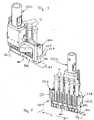
- Figures 4 and 5show an enlarged view of the gripper 222 of the robotic arm 220.
- the gripper 222comprises a first arm 226 and a second arm 228.
- the two arms 226, 228function according to the principle of tongs, i.e. they can perform a relative movement towards each other in order to grip a primary rack between them.
- the distance between the two arms 226, 228is such that they can grip a primary rack in its longitudinal extension, or with other words, the distance between the two arms in their gripping positioning is slightly larger than the length L of a primary rack PR.
- Each primary rack PRcomprises a first end surface 76 and a second end surface 78, the first end surface 76 having a first surface geometry and the second end surface 78 having a second surface geometry.
- the first end surface 76is a flat surface whereas the second surface 78 geometry has two bevelled edges 78.1 and 78.2. Accordingly and as already described above, the primary racks PR have an orientation due to the geometry of their end surfaces which allows unambiguous identification of the sample tubes positions.
- each of the two arms 226, 228 of the gripper 222has according complementary surfaces.
- the first gripper arm 226has a gripping surface being complementary to the first surface geometry and the second gripping arm having a gripping surface being complementary to the second surface geometry.
- the two arms 226, 228are formed as horizontal tongs so as to encompass and grip the primary rack in a horizontal plane. This avoids rack handling from above and thus the danger of crashing sample tubes being too high or not being fully inserted in the rack opening. It also allows moving primary racks horizontally and inserting them into trays in shelves (cf. Figure 12 ).
- the two arms 226, 228 of the gripper 222each comprise a downwardly extending extension 227, 229 which allows a gripping of the top portion of each end surface 76, 78 of the primary rack PR in order to lift the same up.
- the primary rack PRis then placed in an intermediate or interim parking position 260, the gripper 222 releases the primary rack PR in the parking position 260, the robotic arm 220 lowers the gripper 222 slightly and then the two arms close and fully grip the primary rack with their full gripping surface (cf. Figure 5 ).
- This way, the primary racks PRcan be stocked, e.g. on the platform 212 as rack positioning area, next to each other without losing space even though the gripping is done "from behind”.
- FIGS. 8 to 10show enlarged depictions of the alignment element 230.
- the alignment element 230comprises a substantially rectangular base body 231 with a top surface 232, a bottom surface 233, a first longitudinal side 234, a second longitudinal side 235, and first and second end sides 236.
- the first longitudinal side 234 of the alignment element 230has a substantially flat surface and is provided with two vertical partition extensions 237, dividing the first longitudinal side 234 into a main centre section 234.1 and two smaller adjacent outer sections 234.2.
- the breadth B1 of the main centre section 234.1equals substantially the breadth of the flat first end surface 76 of the primary rack PR so that this end surface of the primary rack can be received in between the two vertical partition extensions 237.
- the breadth B3 of the two smaller outer sections 234.2each equals (B1- ⁇ )/2 wherein ⁇ is the width of the gap between two adjacent alignment elements 230 when positioned on the rack positioning area, i.e. the platform 212.
- the second longitudinal side 235 of the alignment element 230comprises, symmetrically to the two vertical partition extensions 237 of the opposite first longitudinal side 234, two projections 238 with substantially triangular cross-section, creating a second main centre section 235.1 and two smaller second outer sections 235.2.
- a vertical extension 239is provided, similar to the two vertical partition extensions 237 of the opposite first longitudinal side 234 and exactly opposing these.
- the distance between the two vertical extensions 239equals the breadth B1 of the opposing first main centre section 234.1
- the breadth B2 of the second main centre section 235.1 between the two projections 238equals substantially the breadth of the second end surface 78 of the primary rack PR with two bevelled edges so that this bevelled end surface of the primary rack can be received in between the two projections 238.
- the top surface 232 of the alignment element 230may comprise bevelled edges in order to facilitate insertion of a primary rack between the extensions 237, 239 and projections 238.
- the alignment element 230On its bottom side 233, the alignment element 230 has a clip-like positioning element 240 provided in the centre of the bottom side 233. It further comprises two positioning pins 241 diagonally opposing each other.
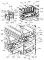
- Figures 11 to 14show a primary rack tray receiver assembly 710 of the invention.
- the primary rack tray receiver assembly 710comprises a receiver skid 712 which is moveable along a skid rail 714.
- the skid rail 714extends along a longitudinal extension of the primary rack tray receiver assembly, the longitudinal extension having a length adapted to accommodate a primary rack tray 720.
- the receiver skid 712is designed to receive a primary rack tray for locking engagement therewith.
- the receiver skid 712comprises receiving and fastening means 716, 718, 722, namely two openings 716 and 718 in its substantially flat top surface which are adapted to engage with corresponding protrusions (not shown) of the primary rack tray 720.
- a retractable bolt 722is provided which is designed to snap into a corresponding recess of the protrusion of the primary rack tray 720 when inserted in the receiver skid 712.
- the snapping direction of the retractable bolt 722may be, for example, perpendicular to the direction of insertion of the primary rack tray 720.
- the empty receiver skid 712is located at one end 740 of the longitudinal extension of the primary rack tray receiver assembly (cf. Figure 12 ). This position might be called the waiting position. Once a primary rack tray 720 is inserted in the receiver skid 712 and fastened thereto, the receiver skid 712 is pushed, together with the inserted primary rack tray 720, along the skid rails 714 out of its waiting position towards an opposing end 742 of the longitudinal extension of the primary rack tray receiver assembly.
- a pivotally arranged barrier gate 738When the primary rack tray 720 is inserted into the primary rack tray receiver assembly, a pivotally arranged barrier gate 738 may be swung downwards.
- the barrier gate 738is slidably coupled to a barrier rail 744 and can be moved longitudinally along the barrier rail 744. The movement may be guided by an electric motor 748 with the effect to apply a controlled push force against a stack of primary racks loaded on the primary rack tray 720. This movement occurs for example after a primary rack has been unloaded from the primary rack tray 720 at the opposing end 742 of the primary rack tray receiver assembly in order to recompose the stack and to ensure that the next primary rack is in an unloading position.
- the primary rack tray 720may comprise a rack trail 746 extending longitudinally along the length of the primary rack tray 720, wherein the rack trail 746 is so designed to slidably engage with a recess 80 located on the bottom side of a primary rack.
- the receiver skid 712 of the inventionmay further comprise a barrier element 724 which is pivotally linked to a longitudinal side of the receiver skid 712 with a first end 726 and being biased into an upwardly inclined position across the open front end 721 of the primary rack tray 720, thus preventing racks PR in the primary rack tray 720 from falling out through the open front end 721 during the insertion and moving procedure as well as during the subsequent handling procedure.
- the barrier element 724may comprise a guide slot 730 with a guide pin 732 of the receiver skid 712 extending therethrough.
- the barrier element 730can be pushed down against its biasing force around the pivotal axis at the first end 726 and along guide slot 730. When pushed down against the biasing force, the open front end 721 of the primary rack tray 720 is set free and the first placed rack PR can be taken out easily. When the barrier element 724 is released, i.e. the pushing down force is taken off, it snaps up again due to the biasing force, thus closing again the open front end 721 of the primary rack tray 720.
- the barrier element 724may comprise at an opposing second end a vertical elongation 728 with the function of an actuating lever.
- Automated pushing down of the barrier element 724 by means of the robotic arm 220can be achieved by means of a corresponding bolt 224 extending from the gripper 222 of the robotic arm 220.
- the bolt 224is attached to the gripper 222 in such a manner that it extends substantially horizontally below the gripper 222 and beyond the outer circumference of a primary rack PR when gripped by the gripper 222 at a front end 76 of the rack PR, i.e. the bolt 224 extends perpendicular to the longitudinal axis of the primary rack PR (cf. Figures 4 and 5 ).
- the robotic arm 220When the robotic arm 220 intends to take up the first place rack PR in the primary rack tray 720, it lowers the gripper 222 down towards the rack PR, with the result that the bolt 224 contacts the upper end of the lever 728. The downward movement of the gripper 222 continues, thus pushing down the barrier element 724 due to the force exerted on the lever 728. Then, the gripper arms 226, 228 grip the rack PR, and the rack PR is then taken out of the primary rack tray 720 with a horizontal movement (which is possible as the barrier element 724 is pushed down).
- the bolt 224extends beyond the outer circumference of the rack PR, the bolt 224 stays in contact with the lever 728 long enough for the rack PR being fully taken out of the primary rack tray, so that the barrier element 724 only snaps up again when the primary rack tray is removed.
- the gate barrier 738is lifted up and the primary rack tray 720 is pulled out of the primary rack tray receiver assembly 710, thereby moving the receiver skid 712 back along the skid rail 714.
- the retractable bolt (722)is retracted out of the recess of the primary rack tray (720) against a biasing force.
- a latching element 734can be provided in order to lock the receiver skid 712 in its movement.
- the latching element 734is arranged somewhat before the ramp-like element 736 so as to allow locking of the movement of the receiver skid 712 without necessarily having to retract the bolt 722. Only if the receiver skid 712 is pulled further back against the ramp-like element 736, the bolt 722 will be retracted and the primary rack tray 720 released.
- Figure 12further illustrates a rack shelf system 750 comprising a plurality of shelf compartments 752, each of the shelf compartments comprising a primary rack tray receiver assembly of the invention and as described above.
- the rack shelf system 750 of the inventionallows handling of laboratory sample tube racks in a high number even if only little space is available.
- the rack shelf system 750works particularly well in combination with the robotic gripper 222 as described and disclosed herein which allows a horizontal gripping of the primary racks RP as this opens the possibility to also insert, i.e. load primary racks PR into rack place in a shelf with a horizontal movement (which is not possible with a gripper gripping racks from above).
- This loading procedureworks analogously to the above-described unloading procedure of racks from a primary rack tray.
- upper or top shelf tray receiver assembliesreceive rack trays loaded with primary racks to be unloaded (by the robotic arm 220), while lower shelf compartments receive empty rack trays to be loaded with primary racks.
Landscapes
- Chemical & Material Sciences (AREA)
- Biochemistry (AREA)
- Physics & Mathematics (AREA)
- Health & Medical Sciences (AREA)
- Life Sciences & Earth Sciences (AREA)
- Analytical Chemistry (AREA)
- General Health & Medical Sciences (AREA)
- General Physics & Mathematics (AREA)
- Immunology (AREA)
- Pathology (AREA)
- Chemical Kinetics & Catalysis (AREA)
- Engineering & Computer Science (AREA)
- Robotics (AREA)
- Automatic Analysis And Handling Materials Therefor (AREA)
Description
- The present invention relates to the handling of sample tube racks in a laboratory environment, and particularly to a laboratory device for handling sample tube racks in the context of storing such sample tubes in a storage compartment, and more particularly of placing tube racks on rack positioning areas or trays.
- In laboratories, such as for example clinical laboratories in which patient samples are examined and submitted to various in-vitro diagnosis tests, test tubes containing samples (such as blood, urine, etc.) have to be handled in high number and in a cautious but still efficient manner. For years now, automated procedures with corresponding systems and devices have been used in this context.
- One aspect during the handling of these sample tubes relates to the tubes being placed in a storage compartment, which can be, for example, a refrigerating device. For efficient handling purposes, the tubes are not handled individually but placed in so-called storage racks. In analysers for chemical, microbiological or clinical tests, the racks are usually placed on rack carriers called trays for all further handling (transporting, charging, discharging). Usually, the trays are charged/discharged at an operating height of about 800 mm. Manual handling of the trays, especially charging/discharging of storage racks, becomes difficult when a high number of trays has to be handled.
- Document
JP 2007/303960 - United States Patent
5,417,922 discloses a specimen carrier for transporting conventional specimen tubes throughout an automatic laboratory conveyance system includes a generally rectilinear carrier body with a forward face having an identification zone delimited thereon. An identification code is marked in the identification zone so as to permit mechanical sensing and identification of the carrier on a conveyor system. A plurality of holes of various diameters and depths are provided in the top surface of the carrier to receive conventional specimen tubes of various types with the top ends of the specimen tubes located at a predetermined height above the top surface of the carrier. - The present invention provides a rack tray receiver assembly with the features of claim 1 a laboratory system comprising said receiver assembly to handle sample tube racks with the features of claims 4 and 5, respectively.
- The laboratory system to handle laboratory sample tube racks comprises a handling device with a gripper for gripping primary racks. The primary racks to be handled comprise a first end surface and a second end surface, the first end surface having a first surface geometry and the second end surface having a second surface geometry, and with the first and second surface geometries being different from each other. The gripper comprises a first gripping arm and a second gripping arm, with the first gripping arm having a gripping surface being complementary to the first surface geometry, and the second gripping arm having a gripping surface being complementary to the second surface geometry.
- Thus, the storage racks with a specific geometry can be handled automatically with a gripper with two gripper arms comprising corresponding complementary geometries, respectively. This enables a secure automated handling of the racks due to the adapted geometry.
- The laboratory system can further comprise an alignment element for aligning primary racks on a primary rack positioning area of a laboratory system. As above, a primary rack to be aligned comprises a first end surface and a second end surface, the first end surface having a first surface geometry and the second end surface having a second surface geometry. The alignment element has a bottom side, a first longitudinal side and a second longitudinal side, wherein the first longitudinal side is complementary to the first surface geometry and the second longitudinal side is complementary to the second surface geometry while the bottom side comprises a nose-like positioning element for positioning the alignment element on the primary rack positioning area in uniform orientation with other alignment elements.
- Thus, automated handling of primary racks with a specific geometry is facilitated by ensuring correct (aligned) placement of primary racks on a rack positioning area.
- Further features and embodiments will become apparent from the description and the accompanying drawings.
- The scope of the invention is defined by the appended claims.
- Various implementations are schematically illustrated in the drawings by means of an embodiment by way of example and are hereinafter explained in detail with reference to the drawings. It is understood that the description is in no way limiting on the scope of the present disclosure and is merely an illustration of a preferred embodiment.
Figure 1 shows a perspective view of a laboratory equipment unit comprising a laboratory system which can comprise the rack tray receiver assembly of the invention.Figure 2 shows a top view of a primary rack handler area of the laboratory system which can comprise the rack tray receiver assembly of the invention where incoming primary racks are handled.Figure 3 shows a perspective view of the primary rack handler area ofFigure 2 .Figure 4 shows a rear perspective view of a gripper of a robotic arm of the primary rack handler area ofFigure 2 .Figure 5 shows a front perspective view of the gripper ofFigure 4 .Figure 6 shows a detail perspective view of the primary rack handler area ofFigures 2 and3 .Figure 7 shows a top view of the detail ofFigure 6 .Figure 8 shows a first perspective top view of an alignment element.Figure 9 shows a second perspective top view of the alignment element ofFigure 8 .Figure 10 shows s perspective bottom view of the alignment element ofFigure 8 .Figure 11 shows a perspective view of a primary rack tray receiver assembly with barrier mechanism according to the invention.Figure 12 shows another perspective view of a primary rack tray receiver assembly of the invention.Figure 13 shows a further perspective view of the primary rack tray receiver assembly ofFigure 12 .Figure 14 shows a plan top view of the primary rack tray receiver assembly ofFigure 12 .- Reference will now be made in detail to some embodiments, examples of which are illustrated in the accompanying drawings. Wherever possible, the same reference numbers are used throughout the drawings to refer to the same or like parts.
Figure 1 shows a perspective view of alaboratory equipment unit 10 comprising a laboratory system. Thislaboratory equipment unit 10 may be a so-called storage retrieval module (SRM) forming part of an overall laboratory analyser system. The storage retrieval module comprises a primary rack handler section 12 (on the left hand side of the depiction ofFigure 1 ) and a refrigerating or storage section 14 (on the right hand side of the depiction ofFigure 1 ). Between the twosections rack handler section 12 into the refrigerating orcooling section 14 and back (in case of retrieval). This loading/unloading interface may be designed like a gate or the like.- The
storage section 14 may comprise arefrigerator 16. A storage section in the context of this invention is a cabinet of various size which is able to store a plurality of sample tubes, preferably in storage racks. It may have an appropriate tempering unit to hold the ambient temperature for the tubes within the refrigerator below room temperature, possibly below 18 °C and possibly below 10 °C. - In its inside, the
storage section 16 comprises a plurality of shelves for storage of a high number of sample tube racks. According to the invention, the sample tube racks loaded into the storage section are so-called storage racks. This implies that all tubes contained in primary racks (i.e. incoming racks of various types) fulfilling the geometry criteria of the invention are taken out of their respective primary racks and are resorted in suitable storage racks before being loaded into thestorage section 14. The storage section may be large enough for one or two human beings being able to enter the inside of thestorage section 14 through a door (not shown). In case the door is opened, a safety switching circuit ensures that all moving systems (like robotic arms or other transfer or conveying systems) come to a standstill, for example in a neutral or home position. While primary racks are single-row racks with somewhat standard geometry and therefore easy to handle in a plurality of different laboratory systems, the secondary racks and particularly the storage racks are multi-row racks (e.g. three rows with more than ten positions, for example 13 to 14 positions). Therefore, the secondary racks are more stable, particularly for storing purposes, and less likely to tilt over. - Further, the
storage section 14 may comprise adisposal unit 18. Thedisposal unit 18 is connected with thestorage section 14 via an internal opening (not shown) in a wall separating thestorage section 14 from thedisposal unit 18. Through this opening, sample tubes whose expiration date (i.e. shelf life) has elapsed can be disposed automatically through thedisposal unit 18. - The primary
rack handler section 12 has a housing consisting of several outer walls with windows so that operating personal can have a direct visual overview of the rack handler's functioning. The primaryrack handler section 12 comprises anopening 20 in one of the outer walls through which primary racks can be inserted into thestorage retrieval module 10. Theopening 20 leads to a primary rack handler area 210 (cf.Figure 2 ) which comprises at least one robotic arm 220 (which can be seen in the depiction ofFigure 1 through one of the windows). Theopening 20 might be closable by means of a sliding or retractable door (not shown). - The primary
rack handler section 12 further comprisesdrawers 22, 24 through which emptied primary racks and/or primary racks containing sample tubes with error designations and/or racks containing at least one retrieved sample tube can be taken out of thestorage retrieval module 10. - Further, the primary
rack handler section 12 comprises acapping station 26 with a feeder tank 28 for tube caps. - The
storage retrieval module 10 also comprises a man-machine interface (MMI) 30 which might have the form of a touch screen monitor 32 at the end of an articulatedarm 34. Figure 2 shows a top view of the primary rack handler area 210 of the laboratory system of the invention andFigure 3 shows a perspective view thereof. The primary rack handler area 210 comprises aplatform 212 inside the primaryrack handler section 12 ofFigure 1 . It further comprises a firstrobotic arm 220 which may be installed essentially in the centre of theplatform 212 or at least at a position from which it can reach at least all locations within the primary rack handler area 210. Any known suitable robot can be used for this purpose, such as for example a SCARA robot with four axes and four degrees of freedom. Therobotic arm 220 comprises, at its end, agripper 222 designed to securely grip the racks to be handled.- On the
platform 212, aconveyor 214 is provided for conveying incoming primary racks PR containing sample tubes (e.g. five sample tubes) to animage analysing unit 250 which is also positioned on theplatform 212. - Further, a plurality of
alignment elements 230 are provided on theplatform 212. Thealignment elements 230 are designed to hold in place the primary racks PR in a desired alignment or orientation which corresponds to an orientation of thegripper 222 of therobotic arm 220. In order to ensure proper orientation of the primary racks PR in every step of processing (such that the sample tubes positions are always unambiguously identifiable), the primary racks may not be introduced directly on theconveyor 214 through theopening 20 but rather be taken up by thegripper 222 ofrobotic arm 220 and then placed on theconveyor 214. For this, a receiving position (not shown) for incoming racks is provided from which the robotic arm then takes up the incoming rack in order to place it onto theconveyor 214. - The
conveyor 214 conveys the primary rack into theimage analysing unit 250 where the sample tubes in the primary rack are analysed as to their geometry parameters. The determined geometry parameters of each sample tube are compared with predetermined geometry criteria and it is identified whether a sample tube is system conform or not. One of the geometry parameters to be analysed is the presence of a cap on the sample tube, and another geometry parameter to be analysed is the tube's diameter. - In case a sample tube is found to have no cap, the whole primary rack is sent to the capping station 26 (not shown in
Figure 3 ) before any other further processing of the primary rack or any of the other sample tubes contained therein. For this, the firstrobotic arm 220 places the primary rack onto theconveyor 260 conveying the primary rack with its sample tubes into thecapping station 26 for a re-capping of the sample tube(s) identified to have no cap. After successful re-capping of the sample tube(s), the primary rack is brought back into the regular processing. Alternatively, as the case may be, the primary rack can be transferred back into theimage analysing unit 250 in order to make sure that now all sample tubes carry a cap and are fit for further processing. Figures 4 and 5 show an enlarged view of thegripper 222 of therobotic arm 220. Thegripper 222 comprises afirst arm 226 and asecond arm 228. The twoarms arms - Each primary rack PR comprises a
first end surface 76 and asecond end surface 78, thefirst end surface 76 having a first surface geometry and thesecond end surface 78 having a second surface geometry. In the embodiment of the drawings, thefirst end surface 76 is a flat surface whereas thesecond surface 78 geometry has two bevelled edges 78.1 and 78.2. Accordingly and as already described above, the primary racks PR have an orientation due to the geometry of their end surfaces which allows unambiguous identification of the sample tubes positions. - In order to be able to properly and safely grip the primary racks, each of the two
arms gripper 222 has according complementary surfaces. Namely, thefirst gripper arm 226 has a gripping surface being complementary to the first surface geometry and the second gripping arm having a gripping surface being complementary to the second surface geometry. - Further, the two
arms Figure 12 ). - In order to be able to grip primary racks from above when several racks are placed next to each other as illustrated in
Figures 6 and 7 , the twoarms gripper 222 each comprise a downwardly extendingextension 227, 229 which allows a gripping of the top portion of eachend surface interim parking position 260, thegripper 222 releases the primary rack PR in theparking position 260, therobotic arm 220 lowers thegripper 222 slightly and then the two arms close and fully grip the primary rack with their full gripping surface (cf.Figure 5 ). This way, the primary racks PR can be stocked, e.g. on theplatform 212 as rack positioning area, next to each other without losing space even though the gripping is done "from behind". Figures 8 to 10 show enlarged depictions of thealignment element 230. Thealignment element 230 comprises a substantiallyrectangular base body 231 with atop surface 232, abottom surface 233, a firstlongitudinal side 234, a secondlongitudinal side 235, and first and second end sides 236.- The first
longitudinal side 234 of thealignment element 230 has a substantially flat surface and is provided with twovertical partition extensions 237, dividing the firstlongitudinal side 234 into a main centre section 234.1 and two smaller adjacent outer sections 234.2. The breadth B1 of the main centre section 234.1 equals substantially the breadth of the flatfirst end surface 76 of the primary rack PR so that this end surface of the primary rack can be received in between the twovertical partition extensions 237. The breadth B3 of the two smaller outer sections 234.2 each equals (B1-Δ)/2 wherein Δ is the width of the gap between twoadjacent alignment elements 230 when positioned on the rack positioning area, i.e. theplatform 212. As a result of this geometry of the invention, an accordingend surface 76 of the primary rack PR can also be received in between twovertical partition extensions 237 ofadjacent alignment elements 230 which allows an optimised use of the available space for stocking or interim-parking the primary racks. - The second
longitudinal side 235 of thealignment element 230 comprises, symmetrically to the twovertical partition extensions 237 of the opposite firstlongitudinal side 234, twoprojections 238 with substantially triangular cross-section, creating a second main centre section 235.1 and two smaller second outer sections 235.2. At the peak of each of theprojections 238, respectively, avertical extension 239 is provided, similar to the twovertical partition extensions 237 of the opposite firstlongitudinal side 234 and exactly opposing these. Therefore, the distance between the twovertical extensions 239 equals the breadth B1 of the opposing first main centre section 234.1, whereas the breadth B2 of the second main centre section 235.1 between the twoprojections 238 equals substantially the breadth of thesecond end surface 78 of the primary rack PR with two bevelled edges so that this bevelled end surface of the primary rack can be received in between the twoprojections 238. Again, the breadth B4 of the two second outer sections 235.2 each equals half of the breadth B2 minus half of the gap between two alignment elements, i.e. B4 = (B2- Δ)/2. - The
top surface 232 of thealignment element 230 may comprise bevelled edges in order to facilitate insertion of a primary rack between theextensions projections 238. - On its
bottom side 233, thealignment element 230 has a clip-like positioning element 240 provided in the centre of thebottom side 233. It further comprises two positioningpins 241 diagonally opposing each other. Figures 11 to 14 show a primary racktray receiver assembly 710 of the invention.- The primary rack
tray receiver assembly 710 comprises areceiver skid 712 which is moveable along askid rail 714. Theskid rail 714 extends along a longitudinal extension of the primary rack tray receiver assembly, the longitudinal extension having a length adapted to accommodate aprimary rack tray 720. - The
receiver skid 712 is designed to receive a primary rack tray for locking engagement therewith. To this end, thereceiver skid 712 comprises receiving and fastening means 716, 718, 722, namely twoopenings primary rack tray 720. In at least one of theopenings 716, aretractable bolt 722 is provided which is designed to snap into a corresponding recess of the protrusion of theprimary rack tray 720 when inserted in thereceiver skid 712. The snapping direction of theretractable bolt 722 may be, for example, perpendicular to the direction of insertion of theprimary rack tray 720. - The
empty receiver skid 712 is located at oneend 740 of the longitudinal extension of the primary rack tray receiver assembly (cf.Figure 12 ). This position might be called the waiting position. Once aprimary rack tray 720 is inserted in thereceiver skid 712 and fastened thereto, thereceiver skid 712 is pushed, together with the insertedprimary rack tray 720, along the skid rails 714 out of its waiting position towards an opposingend 742 of the longitudinal extension of the primary rack tray receiver assembly. - When the
primary rack tray 720 is inserted into the primary rack tray receiver assembly, a pivotally arrangedbarrier gate 738 may be swung downwards. Thebarrier gate 738 is slidably coupled to abarrier rail 744 and can be moved longitudinally along thebarrier rail 744. The movement may be guided by anelectric motor 748 with the effect to apply a controlled push force against a stack of primary racks loaded on theprimary rack tray 720. This movement occurs for example after a primary rack has been unloaded from theprimary rack tray 720 at theopposing end 742 of the primary rack tray receiver assembly in order to recompose the stack and to ensure that the next primary rack is in an unloading position. - In order to improve stability and movement of the primary rack from one end of the
primary rack tray 720 to the other, theprimary rack tray 720 may comprise arack trail 746 extending longitudinally along the length of theprimary rack tray 720, wherein therack trail 746 is so designed to slidably engage with arecess 80 located on the bottom side of a primary rack. - The
receiver skid 712 of the invention may further comprise abarrier element 724 which is pivotally linked to a longitudinal side of thereceiver skid 712 with afirst end 726 and being biased into an upwardly inclined position across the openfront end 721 of theprimary rack tray 720, thus preventing racks PR in theprimary rack tray 720 from falling out through the openfront end 721 during the insertion and moving procedure as well as during the subsequent handling procedure. Thebarrier element 724 may comprise aguide slot 730 with aguide pin 732 of thereceiver skid 712 extending therethrough. - The
barrier element 730 can be pushed down against its biasing force around the pivotal axis at thefirst end 726 and alongguide slot 730. When pushed down against the biasing force, the openfront end 721 of theprimary rack tray 720 is set free and the first placed rack PR can be taken out easily. When thebarrier element 724 is released, i.e. the pushing down force is taken off, it snaps up again due to the biasing force, thus closing again the openfront end 721 of theprimary rack tray 720. - In order to facilitate the pushing down of the
barrier element 724, thebarrier element 724 may comprise at an opposing second end avertical elongation 728 with the function of an actuating lever. Automated pushing down of thebarrier element 724 by means of therobotic arm 220 can be achieved by means of acorresponding bolt 224 extending from thegripper 222 of therobotic arm 220. Thebolt 224 is attached to thegripper 222 in such a manner that it extends substantially horizontally below thegripper 222 and beyond the outer circumference of a primary rack PR when gripped by thegripper 222 at afront end 76 of the rack PR, i.e. thebolt 224 extends perpendicular to the longitudinal axis of the primary rack PR (cf.Figures 4 and 5 ). - When the
robotic arm 220 intends to take up the first place rack PR in theprimary rack tray 720, it lowers thegripper 222 down towards the rack PR, with the result that thebolt 224 contacts the upper end of thelever 728. The downward movement of thegripper 222 continues, thus pushing down thebarrier element 724 due to the force exerted on thelever 728. Then, thegripper arms primary rack tray 720 with a horizontal movement (which is possible as thebarrier element 724 is pushed down). Because thebolt 224 extends beyond the outer circumference of the rack PR, thebolt 224 stays in contact with thelever 728 long enough for the rack PR being fully taken out of the primary rack tray, so that thebarrier element 724 only snaps up again when the primary rack tray is removed. - If a
primary rack tray 720 is to be removed from the primary rack tray receiver assembly, thegate barrier 738 is lifted up and theprimary rack tray 720 is pulled out of the primary racktray receiver assembly 710, thereby moving thereceiver skid 712 back along theskid rail 714. When the receiver skid is brought back into its waiting position, the retractable bolt (722) is retracted out of the recess of the primary rack tray (720) against a biasing force. In more detail. when thereceiver skid 712 reaches its waiting position at 740, the biasing mechanism of theretractable bolt 722 hits a ramp-like element 736 on the bottom of the primary rack tray receiver assembly which causes thebolt 722 to be retracted against its biasing force and thus to unlock theprimary rack tray 720 in thereceiver skid 712 so that theprimary rack tray 720 can be removed. Additionally, a latchingelement 734 can be provided in order to lock thereceiver skid 712 in its movement. Preferably, the latchingelement 734 is arranged somewhat before the ramp-like element 736 so as to allow locking of the movement of thereceiver skid 712 without necessarily having to retract thebolt 722. Only if thereceiver skid 712 is pulled further back against the ramp-like element 736, thebolt 722 will be retracted and theprimary rack tray 720 released. Figure 12 further illustrates arack shelf system 750 comprising a plurality of shelf compartments 752, each of the shelf compartments comprising a primary rack tray receiver assembly of the invention and as described above. Therack shelf system 750 of the invention allows handling of laboratory sample tube racks in a high number even if only little space is available. Therack shelf system 750 works particularly well in combination with therobotic gripper 222 as described and disclosed herein which allows a horizontal gripping of the primary racks RP as this opens the possibility to also insert, i.e. load primary racks PR into rack place in a shelf with a horizontal movement (which is not possible with a gripper gripping racks from above). This loading procedure works analogously to the above-described unloading procedure of racks from a primary rack tray.- According to one aspect of the invention, upper or top shelf tray receiver assemblies receive rack trays loaded with primary racks to be unloaded (by the robotic arm 220), while lower shelf compartments receive empty rack trays to be loaded with primary racks.
Claims (11)
- A rack tray receiver assembly (710) for receiving a rack tray (720) with an open front end (721) through which a rack from a stack of racks (PR) loaded in the tray can be taken out, the rack tray receiver assembly comprising a receiver skid (712) movable along a skid rail (714), the receiver skid (712) comprising receiving and fastening means (716, 718, 722) for fastening the rack tray (720) on the receiver skid (712), the receiver skid (712) being designed for insertion of the rack tray (720) into the receiving and fastening means (716, 718, 722) with the open front end (721) of the rack tray (720) abutting to a barrier element (724) of the receiver skid (712), the barrier element (724) being pivotally linked to the receiver skid (712) with a first end (726), wherein the barrier element (724) is biased into an upwardly inclined position across the open front end (721) of the rack tray (720), thereby preventing racks (PR) in the rack tray (720) from falling out through the open front end (721) and wherein the barrier element (724) can be pushed down against its biasing force around the pivotal axis for setting free the open front end of the rack tray (720) so that the first placed rack (PR) can be taken out easily.
- The rack tray receiver assembly of claim 1, having a longitudinal extension with a length adapted to accommodate a rack tray (720), wherein the empty receiver skid (712) is located at one end (740) of the longitudinal extension in its waiting position and is pushed along the skid rail (714) to the opposing end (742) of the longitudinal extension when a rack tray (720) is inserted.
- A rack tray receiver assembly according to claim 2, wherein the receiving and fastening means (716, 718, 722) comprise a retractable bolt (722) which snaps into a corresponding recess of the rack tray (720) when the rack tray (720) is inserted in the receiver skid (712) and the receiver skid (712) being moved out of its waiting position.
- A laboratory system to handle laboratory sample tube racks, comprising a rack shelf (750) with a plurality of shelf compartments (752), wherein each shelf compartment (752) comprises a rack tray receiver assembly (710) according to any one of claims 1 to 3.
- A laboratory system to handle laboratory sample tube racks, comprising at least one rack tray receiver assembly (710) according to any one of claims 1 to 3, and further comprising a robotic arm (220) with a gripper (222) for gripping primary racks (PR), wherein the gripper (222) further comprises a locking/unlocking bolt (224) for unlocking the barrier element (724).
- The laboratory system to handle laboratory sample tube racks according to claim 5, wherein the primary racks (PR) to be handled comprise a first end surface (76) and a second end surface (78), the first end surface (76) having a first surface geometry and the second end surface (78) having a second surface geometry, and wherein the gripper (222) comprises a first gripping arm (226) and a second gripping arm (228), with the first gripping arm (226) having a gripping surface being complementary to the first surface geometry, and the second gripping arm (228) having a gripping surface being complementary to the second surface geometry.
- The laboratory system of claim 6, wherein the first surface (76) geometry is a flat surface, and the second surface (78) geometry has two bevelled edges (78.1).
- The laboratory system of claim 6 or 7, wherein the first and second gripping arms (226, 228) are formed as horizontal tongs so as to encompass and grip the primary rack (PR) in a horizontal plane.
- The laboratory system of any one of claims 6 to 8, wherein the gripping arms (226, 228) each comprise a downwardly extending extension (227, 229), respectively, which allows a gripping of a top portion of each end surface (76, 78) of the primary rack (PR).
- The laboratory system of any one of claims 6 to 9, further comprising a rack positioning area (212) and an alignment element (230) for aligning racks (PR) on the rack positioning area (212), with the alignment element (230) having a bottom side (233), a first longitudinal side (234) and a second longitudinal side (235), wherein the first longitudinal side (234) is complementary to the first surface geometry and the second longitudinal side (235) is complementary to the second surface geometry while the bottom side (233) comprises a clip-like positioning element (240) for positioning the alignment element (230) on the rack positioning area (212) in uniform orientation with other alignment elements (230).
- The laboratory system of claim 10, wherein the first surface geometry is a flat surface, and the second surface geometry has two bevelled edges (78.1).
Priority Applications (6)
| Application Number | Priority Date | Filing Date | Title |
|---|---|---|---|
| EP08013459.6AEP2148206B1 (en) | 2008-07-25 | 2008-07-25 | A laboratory system for handling sample tube racks, an alignmemt element for sample tube racks and a rack tray receiver assembly |
| EP12004756.8AEP2530025B1 (en) | 2008-07-25 | 2008-07-25 | Alignment element for sample tube racks |
| US12/460,822US8580195B2 (en) | 2008-07-25 | 2009-07-23 | Laboratory system for handling sample tube racks, an alignment element for sample tube racks and a rack tray receiver assembly |
| JP2009172310AJP5202464B2 (en) | 2008-07-25 | 2009-07-23 | Laboratory system for handling sample test tube racks, array elements for sample test tube racks and rack tray receiving assemblies |
| JP2013023645AJP5566484B2 (en) | 2008-07-25 | 2013-02-08 | Laboratory system for handling sample test tube racks, array elements for sample test tube racks and rack tray receiving assemblies |
| US14/048,338US9297822B2 (en) | 2008-07-25 | 2013-10-08 | Laboratory system for handling sample tube racks, an alignment element for sample tube racks and a rack tray receiver assembly |
Applications Claiming Priority (1)
| Application Number | Priority Date | Filing Date | Title |
|---|---|---|---|
| EP08013459.6AEP2148206B1 (en) | 2008-07-25 | 2008-07-25 | A laboratory system for handling sample tube racks, an alignmemt element for sample tube racks and a rack tray receiver assembly |
Related Child Applications (3)
| Application Number | Title | Priority Date | Filing Date |
|---|---|---|---|
| EP12004756.8ADivisionEP2530025B1 (en) | 2008-07-25 | 2008-07-25 | Alignment element for sample tube racks |
| EP12004756.8APreviously-Filed-ApplicationEP2530025B1 (en) | 2008-07-25 | 2008-07-25 | Alignment element for sample tube racks |
| EP12004756.8ADivision-IntoEP2530025B1 (en) | 2008-07-25 | 2008-07-25 | Alignment element for sample tube racks |
Publications (2)
| Publication Number | Publication Date |
|---|---|
| EP2148206A1 EP2148206A1 (en) | 2010-01-27 |
| EP2148206B1true EP2148206B1 (en) | 2015-11-18 |
Family
ID=40120413
Family Applications (2)
| Application Number | Title | Priority Date | Filing Date |
|---|---|---|---|
| EP08013459.6AActiveEP2148206B1 (en) | 2008-07-25 | 2008-07-25 | A laboratory system for handling sample tube racks, an alignmemt element for sample tube racks and a rack tray receiver assembly |
| EP12004756.8AActiveEP2530025B1 (en) | 2008-07-25 | 2008-07-25 | Alignment element for sample tube racks |
Family Applications After (1)
| Application Number | Title | Priority Date | Filing Date |
|---|---|---|---|
| EP12004756.8AActiveEP2530025B1 (en) | 2008-07-25 | 2008-07-25 | Alignment element for sample tube racks |
Country Status (3)
| Country | Link |
|---|---|
| US (2) | US8580195B2 (en) |
| EP (2) | EP2148206B1 (en) |
| JP (2) | JP5202464B2 (en) |
Families Citing this family (53)
| Publication number | Priority date | Publication date | Assignee | Title |
|---|---|---|---|---|
| AU2003272152A1 (en)* | 2002-10-22 | 2004-05-13 | Umc Utrecht Holding B.V. | System for remote transfer of a monitoring signal |
| EP2148204B1 (en)* | 2008-07-25 | 2013-01-02 | F. Hoffmann-La Roche AG | A laboratory storage and retrieval system and a method to handle laboratory sample tubes |
| EP2148206B1 (en) | 2008-07-25 | 2015-11-18 | F.Hoffmann-La Roche Ag | A laboratory system for handling sample tube racks, an alignmemt element for sample tube racks and a rack tray receiver assembly |
| EP2458387A3 (en)* | 2010-11-30 | 2013-09-18 | Kabushiki Kaisha Yaskawa Denki | specimen processing system |
| USD676571S1 (en)* | 2011-07-26 | 2013-02-19 | Randox Laboratories Ltd. | Biochip well |
| BR112014011043A2 (en)* | 2011-11-07 | 2017-06-13 | Beckman Coulter Inc | specimen container detection |
| US9381524B2 (en) | 2011-11-08 | 2016-07-05 | Becton, Dickinson And Company | System and method for automated sample preparation |
| JP6054726B2 (en)* | 2011-12-06 | 2016-12-27 | 平田機工株式会社 | Sorting device |
| ES2654215T3 (en)* | 2012-01-30 | 2018-02-12 | F. Hoffmann-La Roche Ag | Sample rack handling unit |
| TWI481804B (en)* | 2012-10-03 | 2015-04-21 | Wei Hua Chaing | Automatic rail guided vehicle for manufacturing medicament |
| EP2746775B1 (en)* | 2012-12-19 | 2019-09-04 | F.Hoffmann-La Roche Ag | Device and process for transferring reaction vessels |
| AU2013202805B2 (en)* | 2013-03-14 | 2015-07-16 | Gen-Probe Incorporated | System and method for extending the capabilities of a diagnostic analyzer |
| JP6161203B2 (en)* | 2013-11-19 | 2017-07-12 | 株式会社椿本チエイン | Cryogenic containment system |
| ES2882303T3 (en) | 2013-12-10 | 2021-12-01 | Hoffmann La Roche | Tube rack transfer device and diagnostic instrument |
| EP3163309B1 (en)* | 2014-06-26 | 2021-07-28 | Hitachi High-Tech Corporation | Automatic analytical apparatus |
| US10252860B2 (en) | 2015-01-09 | 2019-04-09 | HighRes Biosolutions, Inc. | Modular sample storage system |
| EP3056320B1 (en) | 2015-02-10 | 2018-12-05 | F. Hoffmann-La Roche AG | Robotic device and laboratory automation system comprising robotic device |
| JP6651380B2 (en)* | 2015-02-27 | 2020-02-19 | キヤノンメディカルシステムズ株式会社 | Clinical test equipment |
| WO2016181466A1 (en) | 2015-05-11 | 2016-11-17 | 株式会社安川電機 | Dispensing system, controller, and control method |
| US10837977B2 (en)* | 2015-05-11 | 2020-11-17 | Kabushiki Kaisha Yaskawa Denki | Rack for dispensing and dispensing system |
| ES2920382T3 (en) | 2015-11-16 | 2022-08-03 | Beckman Coulter Inc | Sample tube rack and sample tube analysis system |
| ES2972583T3 (en)* | 2016-04-22 | 2024-06-13 | Becton Dickinson Co | Automated diagnostic analyzer and method for its operation |
| WO2017214666A1 (en)* | 2016-06-14 | 2017-12-21 | Justoy Pty Ltd | Plate storage assembly |
| CN105947653A (en)* | 2016-06-21 | 2016-09-21 | 杨辰 | Medical blood collection tube preparation machine based on multi-joint robot |
| USD812243S1 (en) | 2016-07-28 | 2018-03-06 | Beckman Coulter, Inc. | Sample tube rack |
| CN106824343B (en)* | 2017-01-05 | 2023-04-25 | 柳州市妇幼保健院 | An Angle Adjusting Test Tube Rack Fixing Device |
| JP6802724B2 (en) | 2017-02-10 | 2020-12-16 | 株式会社東芝 | Inspection equipment and inspection method |
| EP3593117B1 (en) | 2017-03-08 | 2024-11-27 | Optofluidic Bioassay, LLC | Optofluidic diagnostics system |
| CN110494757B (en)* | 2017-03-24 | 2024-03-15 | 简·探针公司 | System and method for capacitive fluid level detection and handling of containers |
| EP3388839B1 (en) | 2017-04-10 | 2023-08-30 | F. Hoffmann-La Roche AG | Centering unit for diagnostics laboratory transporting compartment |
| WO2018232364A1 (en) | 2017-06-16 | 2018-12-20 | Beckman Coulter, Inc. | Apparatus and method for handling sample containers |
| USD938612S1 (en)* | 2017-06-16 | 2021-12-14 | Beckman Coulter, Inc. | Sample rack |
| EP3454064B1 (en)* | 2017-09-08 | 2020-11-11 | F. Hoffmann-La Roche AG | Rack positioning system |
| US10816565B2 (en) | 2017-12-08 | 2020-10-27 | Michael Doran | Test tube removal device and system |
| JP7325171B2 (en)* | 2018-03-29 | 2023-08-14 | シスメックス株式会社 | Rack transportation method, sample measurement system |
| GB201806509D0 (en)* | 2018-04-20 | 2018-06-06 | Q Linea Ab | Analysis instrument |
| CN108717115B (en)* | 2018-05-29 | 2020-12-04 | 温州广立生物医药科技有限公司 | A detection device for a medical biochemical detector |
| CN108717113B (en)* | 2018-05-29 | 2020-11-03 | 山东华航医学科技有限公司 | Biochemical detector |
| CN108717114B (en)* | 2018-05-29 | 2020-12-04 | 温州广立生物医药科技有限公司 | Sampling detection device of medical biochemical detector |
| JP7528111B2 (en) | 2019-03-07 | 2024-08-05 | ジェン-プローブ・インコーポレーテッド | Systems and methods for transporting and retaining consumables in processing equipment - Patents.com |
| CN110068696A (en)* | 2019-05-28 | 2019-07-30 | 威海威高生物科技有限公司 | Medical disposable material automatic stacking loading device |
| CN111332580A (en)* | 2019-08-06 | 2020-06-26 | 上海十指生物科技有限公司 | Cancer early gene detection kit |
| JP7297946B2 (en)* | 2020-01-28 | 2023-06-26 | 富士フイルム株式会社 | Processing equipment and measurement systems |
| JP7297947B2 (en)* | 2020-01-28 | 2023-06-26 | 富士フイルム株式会社 | Processing equipment and measurement systems |
| CN111890394B (en)* | 2020-08-07 | 2021-08-10 | 基点生物科技(成都)有限公司 | Biological sample test tube clamp |
| CN113559955B (en)* | 2021-01-29 | 2022-07-01 | 广东润鹏生物技术有限公司 | Clamping mechanism and transfer device |
| JP7256839B2 (en)* | 2021-04-14 | 2023-04-12 | 株式会社椿本チエイン | Rack stirrer and stirring system |
| CN114083514B (en)* | 2021-12-10 | 2022-06-17 | 广州华银医学检验中心有限公司 | Intelligent manipulator for discharging test tube samples |
| CN115155689B (en)* | 2022-07-05 | 2024-03-26 | 大连好米咨科技有限公司 | Solid phase extraction module |
| CN115532336A (en)* | 2022-08-12 | 2022-12-30 | 青岛市中心医院 | A convenient and easy-to-operate medical test tube support structure for blood department and its use method |
| CN117088000B (en)* | 2023-09-13 | 2024-12-17 | 中国人民解放军总医院第四医学中心 | Blood gas analysis sample preservation device |
| CN116969053A (en)* | 2023-09-22 | 2023-10-31 | 枣庄市宇辰环保咨询有限公司 | Sample storage device for environmental monitoring |
| WO2025113796A1 (en)* | 2023-11-30 | 2025-06-05 | Abb Schweiz Ag | Unloading assembly and loading assembly for sample processing and/or analyzing system for laboratory automation system |
Family Cites Families (69)
| Publication number | Priority date | Publication date | Assignee | Title |
|---|---|---|---|---|
| US736497A (en)* | 1902-04-02 | 1903-08-18 | Thomas Francis Condon | Clothes stick or lifter. |
| EP0083651B1 (en) | 1981-07-20 | 1987-11-19 | Baxter Travenol Laboratories, Inc. | Loading and transfer assembly for chemical analyzer |
| DE3150672C2 (en)* | 1981-12-21 | 1986-06-05 | Licentia Patent-Verwaltungs-Gmbh, 6000 Frankfurt | Arrangement for positioning a base plate on a worktop |
| FR2551389B1 (en)* | 1983-09-02 | 1987-02-06 | Calhene | MULTIPLE CONTACT PAD GRIPPER |
| JPS60122865A (en) | 1983-12-07 | 1985-07-01 | Hitachi Ltd | Solar heat electric power generation apparatus |
| JPS60122865U (en)* | 1983-12-08 | 1985-08-19 | オリンパス光学工業株式会社 | Container exchange device in automatic analyzer |
| DD229370A1 (en)* | 1984-11-27 | 1985-11-06 | Werkzeugmasch Forschzent | TRANSPORT RANGE WITH CONTINUOUS DRILLING AND FIXING ELEMENTS |
| JPH062140Y2 (en)* | 1988-07-23 | 1994-01-19 | 康信 月岡 | Shaking device for inspection of blood, cells, etc. |
| JPH0411005A (en) | 1990-04-26 | 1992-01-16 | Kuraray Co Ltd | Special cross-section fiber and spinning nozzle |
| DE4023149A1 (en) | 1990-07-20 | 1992-01-23 | Kodak Ag | DEVICE FOR SCANING CONTAINERS WITH A LIQUID |
| EP0523426B1 (en)* | 1991-07-16 | 1996-03-06 | Johnson & Johnson Clinical Diagnostics, Inc. | Device for feeding objects into a waste bin of an analyzer |
| US5696887A (en)* | 1991-08-05 | 1997-12-09 | Biotek Solutions, Incorporated | Automated tissue assay using standardized chemicals and packages |
| US5417922A (en) | 1993-05-14 | 1995-05-23 | Board Of Regents - University Of Nebraska | Specimen carrier |
| JPH0780355A (en)* | 1993-09-14 | 1995-03-28 | Kubota Seisakusho:Kk | Method and apparatus for automatic centrifuge |
| JPH0829432A (en) | 1994-07-15 | 1996-02-02 | Shimadzu Corp | Automatic sample preparation device |
| US5592289A (en)* | 1995-01-09 | 1997-01-07 | Molecular Dynamics | Self-aligning mechanism for positioning analyte receptacles |
| US5620894A (en)* | 1995-06-16 | 1997-04-15 | Glaxo Wellcome Inc. | Apparatus for automated biological cell harvesting |
| JP2947146B2 (en)* | 1995-09-29 | 1999-09-13 | 株式会社島津製作所 | Autosampler |
| JPH09211005A (en) | 1996-01-30 | 1997-08-15 | Olympus Optical Co Ltd | Specimen automatic feed apparatus for examination |
| US5948363A (en)* | 1996-04-22 | 1999-09-07 | Gaillard; Patrick | Micro-well strip with print tabs |
| US7141213B1 (en)* | 1996-07-05 | 2006-11-28 | Beckman Coulter, Inc. | Automated sample processing system |
| AU3651497A (en)* | 1996-07-05 | 1998-02-02 | Beckman Coulter, Inc. | Automated sample processing system |
| JP3032159B2 (en)* | 1996-09-24 | 2000-04-10 | 株式会社日立製作所 | Analysis system |
| JPH10123146A (en)* | 1996-10-18 | 1998-05-15 | Hitachi Ltd | Tray with cap for sample container |
| FR2764704B1 (en)* | 1997-06-16 | 1999-08-20 | Stago Diagnostica | DEVICE FOR THE AUTOMATIC READING OF AN IDENTIFICATION CODE CARRIED BY TUBULAR CONTAINERS |
| US6586255B1 (en)* | 1997-07-21 | 2003-07-01 | Quest Diagnostics Incorporated | Automated centrifuge loading device |
| AUPP058197A0 (en)* | 1997-11-27 | 1997-12-18 | A.I. Scientific Pty Ltd | Pathology sample tube distributor |
| DE19819812C2 (en)* | 1998-05-04 | 2000-11-02 | Olympus Diagnostica Gmbh | Laboratory primary sample distributor with a distribution device |
| US6074617A (en)* | 1998-07-10 | 2000-06-13 | Bayer Corporation | Stat shuttle adapter and transport device |
| US6331437B1 (en)* | 1998-07-14 | 2001-12-18 | Bayer Corporation | Automatic handler for feeding containers into and out of an analytical instrument |
| US6068437A (en)* | 1998-11-24 | 2000-05-30 | Lab-Interlink | Automated laboratory specimen organizer and storage unit |
| DE19912211B4 (en) | 1999-03-18 | 2008-07-03 | Olympus Life And Material Science Europa Gmbh | sample sorter |
| JP2001074752A (en)* | 1999-09-07 | 2001-03-23 | Kyowa Medex Co Ltd | Management system of automatic analyzer |
| JP2001278409A (en)* | 2000-03-31 | 2001-10-10 | Nippon Shooter Ltd | Specimen carrying vehicle and specimen carrying system using it |
| US6746648B1 (en)* | 2000-06-15 | 2004-06-08 | Beckman Coulter, Inc. | Method and system for transporting and storing multiple reagent packs and reagent packs used therein |
| JP2002011686A (en)* | 2000-06-28 | 2002-01-15 | Yazaki Corp | Structure for absorbing misalignment of structures held by a robot arm |
| JP2004507703A (en)* | 2000-08-23 | 2004-03-11 | ユニバーシテイ・オブ・バージニア・パテント・フアウンデーシヨン | Automatic storage / recovery device for freezer and related method |
| US7352889B2 (en)* | 2000-10-30 | 2008-04-01 | Ganz Brian L | Automated storage and retrieval device and method |
| JP3694490B2 (en)* | 2002-03-29 | 2005-09-14 | アロカ株式会社 | Sample pretreatment system |
| JP3740428B2 (en) | 2002-03-29 | 2006-02-01 | アロカ株式会社 | Sample pretreatment system |
| WO2004004886A2 (en)* | 2002-07-05 | 2004-01-15 | Aventis Pharmaceuticals Inc. | Apparatus and method for use in solid phase chemical synthesis |
| WO2004008106A2 (en)* | 2002-07-16 | 2004-01-22 | Ventana Medical Systems, Inc. | Tray for automated histochemical processing |
| FR2842912B1 (en)* | 2002-07-25 | 2004-09-10 | Junior Instruments | PROCESS AND DEVICE FOR THE PRETREATMENT BY CENTRIFUGAL OF SAMPLES. |
| JP2004075363A (en) | 2002-08-21 | 2004-03-11 | Hitachi Koki Co Ltd | Automatic storage device |
| US7364907B2 (en) | 2002-11-08 | 2008-04-29 | Irm Llc | Systems and methods for sorting samples |
| US7314341B2 (en)* | 2003-01-10 | 2008-01-01 | Liconic Ag | Automatic storage device and climate controlled cabinet with such a device |
| EP1496365B1 (en)* | 2003-07-11 | 2014-06-04 | Tecan Trading AG | Device and method for transporting objects |
| US20050118060A1 (en)* | 2003-08-04 | 2005-06-02 | Irm, Llc | Multi-well container positioning devices and related systems and methods |
| ATE370687T1 (en)* | 2003-12-12 | 2007-09-15 | Panini Espana Sa | BOX FOR COLLECTING ITEMS |
| US7850914B2 (en)* | 2004-03-05 | 2010-12-14 | Beckman Coulter, Inc. | Specimen-transport module for a multi-instrument clinical workcell |
| EP1653234A1 (en)* | 2004-10-27 | 2006-05-03 | Roche Diagnostics GmbH | Sampling apparatus comprising a carousel |
| EP1655071A1 (en)* | 2004-11-04 | 2006-05-10 | F. Hoffmann-La Roche Ag | Test tube stand with a movable section for shaking the sample. |
| EP1655609B1 (en)* | 2004-11-04 | 2013-09-18 | F.Hoffmann-La Roche Ag | Test tube stand with a movable section for shaking the sample. |
| JP2006208142A (en)* | 2005-01-27 | 2006-08-10 | Tsubakimoto Chain Co | System for storing sample for drug development |
| CA2967430C (en)* | 2005-03-10 | 2018-05-08 | Gen-Probe Incorporated | Systems and methods to perform assays for detecting or quantifying analytes within samples |
| JP4546863B2 (en)* | 2005-03-28 | 2010-09-22 | シスメックス株式会社 | Transport device |
| US7910067B2 (en)* | 2005-04-19 | 2011-03-22 | Gen-Probe Incorporated | Sample tube holder |
| US7628954B2 (en)* | 2005-05-04 | 2009-12-08 | Abbott Laboratories, Inc. | Reagent and sample handling device for automatic testing system |
| US20060263270A1 (en)* | 2005-05-18 | 2006-11-23 | Beckman Coulter, Inc. | Robotic grip and twist assembly |
| JP3805352B1 (en)* | 2005-05-25 | 2006-08-02 | 株式会社エンプラス | Fluid handling device and fluid handling unit used therefor |
| CN101253515B (en)* | 2005-06-30 | 2012-09-26 | 北美Agc平板玻璃公司 | Monolithic image perception device and method |
| DE602005010083D1 (en)* | 2005-09-21 | 2008-11-13 | Roche Diagnostics Gmbh | Reagent container assembly and analyzer with such arrangement |
| DK2682189T3 (en)* | 2006-01-23 | 2015-06-01 | Nexus Biosystems Inc | Automated system for storage, retrieval and administration of samples |
| JP2007303960A (en) | 2006-05-11 | 2007-11-22 | Olympus Corp | Rack tray |
| US7670555B2 (en)* | 2006-09-08 | 2010-03-02 | Rex A. Hoover | Parallel gripper for handling multiwell plate |
| JP4210306B2 (en)* | 2007-01-15 | 2009-01-14 | 株式会社アイディエス | Test tube automatic opening device |
| US20090028754A1 (en)* | 2007-07-27 | 2009-01-29 | Dade Behring Inc. | Insert for Restraining Tube Rotation in a Sample Tube Rack |
| JP5049769B2 (en)* | 2007-12-25 | 2012-10-17 | 株式会社日立ハイテクノロジーズ | Automatic analyzer and sample processing system |
| EP2148206B1 (en) | 2008-07-25 | 2015-11-18 | F.Hoffmann-La Roche Ag | A laboratory system for handling sample tube racks, an alignmemt element for sample tube racks and a rack tray receiver assembly |
- 2008
- 2008-07-25EPEP08013459.6Apatent/EP2148206B1/enactiveActive
- 2008-07-25EPEP12004756.8Apatent/EP2530025B1/enactiveActive
- 2009
- 2009-07-23USUS12/460,822patent/US8580195B2/enactiveActive
- 2009-07-23JPJP2009172310Apatent/JP5202464B2/enactiveActive
- 2013
- 2013-02-08JPJP2013023645Apatent/JP5566484B2/enactiveActive
- 2013-10-08USUS14/048,338patent/US9297822B2/enactiveActive
Also Published As
| Publication number | Publication date |
|---|---|
| JP2013122465A (en) | 2013-06-20 |
| JP5202464B2 (en) | 2013-06-05 |
| JP5566484B2 (en) | 2014-08-06 |
| EP2530025B1 (en) | 2015-11-04 |
| JP2010032516A (en) | 2010-02-12 |
| US9297822B2 (en) | 2016-03-29 |
| US20100028203A1 (en) | 2010-02-04 |
| EP2530025A1 (en) | 2012-12-05 |
| US8580195B2 (en) | 2013-11-12 |
| US20140037420A1 (en) | 2014-02-06 |
| EP2148206A1 (en) | 2010-01-27 |
Similar Documents
| Publication | Publication Date | Title |
|---|---|---|
| EP2148206B1 (en) | A laboratory system for handling sample tube racks, an alignmemt element for sample tube racks and a rack tray receiver assembly | |
| US8694153B2 (en) | Method and laboratory system for handling sample tube racks | |
| EP2148204B1 (en) | A laboratory storage and retrieval system and a method to handle laboratory sample tubes | |
| ES2949406T3 (en) | Automated analyzer that punctures aspiration caps | |
| CN103080749B (en) | Specimen transfer mechanism | |
| CN109368231B (en) | Feeding and discharging equipment and feeding and discharging method | |
| US20080260511A1 (en) | Stacker | |
| US20170254826A1 (en) | Feeding apparatus | |
| JP4485486B2 (en) | Tube picking device for drug discovery | |
| CN111356926A (en) | Sample analyzer and sample frame transfer structure | |
| EP3388840B1 (en) | Drawer assembly for a laboratory instrument | |
| JP2023523240A (en) | Gripper device with reduced risk of contamination | |
| CN114317230B (en) | Nucleic acid extraction and detection device and nucleic acid extraction and detection method | |
| LU103047B1 (en) | Loading and unloading unix for sample racks | |
| EP4378588B1 (en) | Loading and unloading unit for sample racks | |
| US11561233B2 (en) | System for loading pipette tips | |
| US20240100525A1 (en) | Drawer for Bulk Liquid Supply | |
| CN118150847A (en) | Loading and unloading unit for sample holders | |
| HK1140715A (en) | A method and laboratory system for handling sample tube racks | |
| JP2008237046A (en) | Storage stand and cell culture apparatus capable of storing the storage stand | |
| WO2002020375A2 (en) | Racking system for platform loaded goods and dispensing device for dispensing platform loaded goods | |
| US20200150139A1 (en) | Receptacle terminal |
Legal Events
| Date | Code | Title | Description |
|---|---|---|---|
| PUAI | Public reference made under article 153(3) epc to a published international application that has entered the european phase | Free format text:ORIGINAL CODE: 0009012 | |
| AK | Designated contracting states | Kind code of ref document:A1 Designated state(s):AT BE BG CH CY CZ DE DK EE ES FI FR GB GR HR HU IE IS IT LI LT LU LV MC MT NL NO PL PT RO SE SI SK TR | |
| AX | Request for extension of the european patent | Extension state:AL BA MK RS | |
| 17P | Request for examination filed | Effective date:20100614 | |
| 17Q | First examination report despatched | Effective date:20100722 | |
| AKX | Designation fees paid | Designated state(s):AT BE BG CH CY CZ DE DK EE ES FI FR GB GR HR HU IE IS IT LI LT LU LV MC MT NL NO PL PT RO SE SI SK TR | |
| RIN1 | Information on inventor provided before grant (corrected) | Inventor name:WIDMER, BEAT Inventor name:LACKNER, JOACHIM Inventor name:GOEDL, FRITZ Inventor name:KOCH, BRUNO Inventor name:FREY, ROLF Inventor name:STETTLER, UELI | |
| RIN1 | Information on inventor provided before grant (corrected) | Inventor name:WIDMER, BEAT Inventor name:STETTLER, UELI Inventor name:FREY, ROLF Inventor name:KOCH, BRUNO Inventor name:GOEDL, FRITZ Inventor name:LACKNER, JOACHIM | |
| GRAP | Despatch of communication of intention to grant a patent | Free format text:ORIGINAL CODE: EPIDOSNIGR1 | |
| GRAJ | Information related to disapproval of communication of intention to grant by the applicant or resumption of examination proceedings by the epo deleted | Free format text:ORIGINAL CODE: EPIDOSDIGR1 | |
| GRAP | Despatch of communication of intention to grant a patent | Free format text:ORIGINAL CODE: EPIDOSNIGR1 | |
| INTG | Intention to grant announced | Effective date:20150630 | |
| INTG | Intention to grant announced | Effective date:20150710 | |
| GRAS | Grant fee paid | Free format text:ORIGINAL CODE: EPIDOSNIGR3 | |
| GRAA | (expected) grant | Free format text:ORIGINAL CODE: 0009210 | |
| AK | Designated contracting states | Kind code of ref document:B1 Designated state(s):AT BE BG CH CY CZ DE DK EE ES FI FR GB GR HR HU IE IS IT LI LT LU LV MC MT NL NO PL PT RO SE SI SK TR | |
| REG | Reference to a national code | Ref country code:GB Ref legal event code:FG4D | |
| REG | Reference to a national code | Ref country code:CH Ref legal event code:EP | |
| REG | Reference to a national code | Ref country code:AT Ref legal event code:REF Ref document number:761820 Country of ref document:AT Kind code of ref document:T Effective date:20151215 | |
| REG | Reference to a national code | Ref country code:IE Ref legal event code:FG4D | |
| REG | Reference to a national code | Ref country code:DE Ref legal event code:R096 Ref document number:602008041214 Country of ref document:DE | |
| REG | Reference to a national code | Ref country code:NL Ref legal event code:MP Effective date:20160218 | |
| REG | Reference to a national code | Ref country code:LT Ref legal event code:MG4D | |
| REG | Reference to a national code | Ref country code:AT Ref legal event code:MK05 Ref document number:761820 Country of ref document:AT Kind code of ref document:T Effective date:20151118 | |
| PG25 | Lapsed in a contracting state [announced via postgrant information from national office to epo] | Ref country code:IS Free format text:LAPSE BECAUSE OF FAILURE TO SUBMIT A TRANSLATION OF THE DESCRIPTION OR TO PAY THE FEE WITHIN THE PRESCRIBED TIME-LIMIT Effective date:20160318 Ref country code:IT Free format text:LAPSE BECAUSE OF FAILURE TO SUBMIT A TRANSLATION OF THE DESCRIPTION OR TO PAY THE FEE WITHIN THE PRESCRIBED TIME-LIMIT Effective date:20151118 Ref country code:ES Free format text:LAPSE BECAUSE OF FAILURE TO SUBMIT A TRANSLATION OF THE DESCRIPTION OR TO PAY THE FEE WITHIN THE PRESCRIBED TIME-LIMIT Effective date:20151118 Ref country code:HR Free format text:LAPSE BECAUSE OF FAILURE TO SUBMIT A TRANSLATION OF THE DESCRIPTION OR TO PAY THE FEE WITHIN THE PRESCRIBED TIME-LIMIT Effective date:20151118 Ref country code:LT Free format text:LAPSE BECAUSE OF FAILURE TO SUBMIT A TRANSLATION OF THE DESCRIPTION OR TO PAY THE FEE WITHIN THE PRESCRIBED TIME-LIMIT Effective date:20151118 Ref country code:NL Free format text:LAPSE BECAUSE OF FAILURE TO SUBMIT A TRANSLATION OF THE DESCRIPTION OR TO PAY THE FEE WITHIN THE PRESCRIBED TIME-LIMIT Effective date:20151118 Ref country code:NO Free format text:LAPSE BECAUSE OF FAILURE TO SUBMIT A TRANSLATION OF THE DESCRIPTION OR TO PAY THE FEE WITHIN THE PRESCRIBED TIME-LIMIT Effective date:20160218 | |
| PG25 | Lapsed in a contracting state [announced via postgrant information from national office to epo] | Ref country code:LV Free format text:LAPSE BECAUSE OF FAILURE TO SUBMIT A TRANSLATION OF THE DESCRIPTION OR TO PAY THE FEE WITHIN THE PRESCRIBED TIME-LIMIT Effective date:20151118 Ref country code:GR Free format text:LAPSE BECAUSE OF FAILURE TO SUBMIT A TRANSLATION OF THE DESCRIPTION OR TO PAY THE FEE WITHIN THE PRESCRIBED TIME-LIMIT Effective date:20160219 Ref country code:SE Free format text:LAPSE BECAUSE OF FAILURE TO SUBMIT A TRANSLATION OF THE DESCRIPTION OR TO PAY THE FEE WITHIN THE PRESCRIBED TIME-LIMIT Effective date:20151118 Ref country code:PL Free format text:LAPSE BECAUSE OF FAILURE TO SUBMIT A TRANSLATION OF THE DESCRIPTION OR TO PAY THE FEE WITHIN THE PRESCRIBED TIME-LIMIT Effective date:20151118 Ref country code:PT Free format text:LAPSE BECAUSE OF FAILURE TO SUBMIT A TRANSLATION OF THE DESCRIPTION OR TO PAY THE FEE WITHIN THE PRESCRIBED TIME-LIMIT Effective date:20160318 Ref country code:FI Free format text:LAPSE BECAUSE OF FAILURE TO SUBMIT A TRANSLATION OF THE DESCRIPTION OR TO PAY THE FEE WITHIN THE PRESCRIBED TIME-LIMIT Effective date:20151118 Ref country code:AT Free format text:LAPSE BECAUSE OF FAILURE TO SUBMIT A TRANSLATION OF THE DESCRIPTION OR TO PAY THE FEE WITHIN THE PRESCRIBED TIME-LIMIT Effective date:20151118 | |
| PG25 | Lapsed in a contracting state [announced via postgrant information from national office to epo] | Ref country code:CZ Free format text:LAPSE BECAUSE OF FAILURE TO SUBMIT A TRANSLATION OF THE DESCRIPTION OR TO PAY THE FEE WITHIN THE PRESCRIBED TIME-LIMIT Effective date:20151118 | |
| REG | Reference to a national code | Ref country code:DE Ref legal event code:R097 Ref document number:602008041214 Country of ref document:DE | |
| PG25 | Lapsed in a contracting state [announced via postgrant information from national office to epo] | Ref country code:RO Free format text:LAPSE BECAUSE OF FAILURE TO SUBMIT A TRANSLATION OF THE DESCRIPTION OR TO PAY THE FEE WITHIN THE PRESCRIBED TIME-LIMIT Effective date:20151118 Ref country code:DK Free format text:LAPSE BECAUSE OF FAILURE TO SUBMIT A TRANSLATION OF THE DESCRIPTION OR TO PAY THE FEE WITHIN THE PRESCRIBED TIME-LIMIT Effective date:20151118 Ref country code:SK Free format text:LAPSE BECAUSE OF FAILURE TO SUBMIT A TRANSLATION OF THE DESCRIPTION OR TO PAY THE FEE WITHIN THE PRESCRIBED TIME-LIMIT Effective date:20151118 Ref country code:EE Free format text:LAPSE BECAUSE OF FAILURE TO SUBMIT A TRANSLATION OF THE DESCRIPTION OR TO PAY THE FEE WITHIN THE PRESCRIBED TIME-LIMIT Effective date:20151118 | |
| PLBE | No opposition filed within time limit | Free format text:ORIGINAL CODE: 0009261 | |
| STAA | Information on the status of an ep patent application or granted ep patent | Free format text:STATUS: NO OPPOSITION FILED WITHIN TIME LIMIT | |
| 26N | No opposition filed | Effective date:20160819 | |
| PG25 | Lapsed in a contracting state [announced via postgrant information from national office to epo] | Ref country code:SI Free format text:LAPSE BECAUSE OF FAILURE TO SUBMIT A TRANSLATION OF THE DESCRIPTION OR TO PAY THE FEE WITHIN THE PRESCRIBED TIME-LIMIT Effective date:20151118 | |
| PG25 | Lapsed in a contracting state [announced via postgrant information from national office to epo] | Ref country code:BE Free format text:LAPSE BECAUSE OF FAILURE TO SUBMIT A TRANSLATION OF THE DESCRIPTION OR TO PAY THE FEE WITHIN THE PRESCRIBED TIME-LIMIT Effective date:20151118 | |
| GBPC | Gb: european patent ceased through non-payment of renewal fee | Effective date:20160725 | |
| PG25 | Lapsed in a contracting state [announced via postgrant information from national office to epo] | Ref country code:MC Free format text:LAPSE BECAUSE OF FAILURE TO SUBMIT A TRANSLATION OF THE DESCRIPTION OR TO PAY THE FEE WITHIN THE PRESCRIBED TIME-LIMIT Effective date:20151118 | |
| PG25 | Lapsed in a contracting state [announced via postgrant information from national office to epo] | Ref country code:FR Free format text:LAPSE BECAUSE OF NON-PAYMENT OF DUE FEES Effective date:20160801 | |
| REG | Reference to a national code | Ref country code:FR Ref legal event code:ST Effective date:20170331 | |
| REG | Reference to a national code | Ref country code:IE Ref legal event code:MM4A | |
| PG25 | Lapsed in a contracting state [announced via postgrant information from national office to epo] | Ref country code:GB Free format text:LAPSE BECAUSE OF NON-PAYMENT OF DUE FEES Effective date:20160725 | |
| PG25 | Lapsed in a contracting state [announced via postgrant information from national office to epo] | Ref country code:IE Free format text:LAPSE BECAUSE OF NON-PAYMENT OF DUE FEES Effective date:20160725 | |
| PG25 | Lapsed in a contracting state [announced via postgrant information from national office to epo] | Ref country code:LU Free format text:LAPSE BECAUSE OF NON-PAYMENT OF DUE FEES Effective date:20160725 | |
| PG25 | Lapsed in a contracting state [announced via postgrant information from national office to epo] | Ref country code:HU Free format text:LAPSE BECAUSE OF FAILURE TO SUBMIT A TRANSLATION OF THE DESCRIPTION OR TO PAY THE FEE WITHIN THE PRESCRIBED TIME-LIMIT; INVALID AB INITIO Effective date:20080725 Ref country code:CY Free format text:LAPSE BECAUSE OF FAILURE TO SUBMIT A TRANSLATION OF THE DESCRIPTION OR TO PAY THE FEE WITHIN THE PRESCRIBED TIME-LIMIT Effective date:20151118 | |
| PG25 | Lapsed in a contracting state [announced via postgrant information from national office to epo] | Ref country code:MT Free format text:LAPSE BECAUSE OF NON-PAYMENT OF DUE FEES Effective date:20160731 Ref country code:TR Free format text:LAPSE BECAUSE OF FAILURE TO SUBMIT A TRANSLATION OF THE DESCRIPTION OR TO PAY THE FEE WITHIN THE PRESCRIBED TIME-LIMIT Effective date:20151118 | |
| PG25 | Lapsed in a contracting state [announced via postgrant information from national office to epo] | Ref country code:BG Free format text:LAPSE BECAUSE OF FAILURE TO SUBMIT A TRANSLATION OF THE DESCRIPTION OR TO PAY THE FEE WITHIN THE PRESCRIBED TIME-LIMIT Effective date:20151118 | |
| PGFP | Annual fee paid to national office [announced via postgrant information from national office to epo] | Ref country code:DE Payment date:20240619 Year of fee payment:17 | |
| PGFP | Annual fee paid to national office [announced via postgrant information from national office to epo] | Ref country code:CH Payment date:20240801 Year of fee payment:17 |