EP2147823A1 - Method and device for determining a suitable light distribution of the light emitted by at least one headlamp of a vehicle - Google Patents
Method and device for determining a suitable light distribution of the light emitted by at least one headlamp of a vehicleDownload PDFInfo
- Publication number
- EP2147823A1 EP2147823A1EP09166129AEP09166129AEP2147823A1EP 2147823 A1EP2147823 A1EP 2147823A1EP 09166129 AEP09166129 AEP 09166129AEP 09166129 AEP09166129 AEP 09166129AEP 2147823 A1EP2147823 A1EP 2147823A1
- Authority
- EP
- European Patent Office
- Prior art keywords
- vehicle
- light
- light distribution
- glare
- determined
- Prior art date
- Legal status (The legal status is an assumption and is not a legal conclusion. Google has not performed a legal analysis and makes no representation as to the accuracy of the status listed.)
- Granted
Links
Images


Classifications
- B—PERFORMING OPERATIONS; TRANSPORTING
- B60—VEHICLES IN GENERAL
- B60Q—ARRANGEMENT OF SIGNALLING OR LIGHTING DEVICES, THE MOUNTING OR SUPPORTING THEREOF OR CIRCUITS THEREFOR, FOR VEHICLES IN GENERAL
- B60Q1/00—Arrangement of optical signalling or lighting devices, the mounting or supporting thereof or circuits therefor
- B60Q1/02—Arrangement of optical signalling or lighting devices, the mounting or supporting thereof or circuits therefor the devices being primarily intended to illuminate the way ahead or to illuminate other areas of way or environments
- B60Q1/04—Arrangement of optical signalling or lighting devices, the mounting or supporting thereof or circuits therefor the devices being primarily intended to illuminate the way ahead or to illuminate other areas of way or environments the devices being headlights
- B60Q1/14—Arrangement of optical signalling or lighting devices, the mounting or supporting thereof or circuits therefor the devices being primarily intended to illuminate the way ahead or to illuminate other areas of way or environments the devices being headlights having dimming means
- B60Q1/1415—Dimming circuits
- B60Q1/1423—Automatic dimming circuits, i.e. switching between high beam and low beam due to change of ambient light or light level in road traffic
- B60Q1/143—Automatic dimming circuits, i.e. switching between high beam and low beam due to change of ambient light or light level in road traffic combined with another condition, e.g. using vehicle recognition from camera images or activation of wipers
- B—PERFORMING OPERATIONS; TRANSPORTING
- B60—VEHICLES IN GENERAL
- B60Q—ARRANGEMENT OF SIGNALLING OR LIGHTING DEVICES, THE MOUNTING OR SUPPORTING THEREOF OR CIRCUITS THEREFOR, FOR VEHICLES IN GENERAL
- B60Q2300/00—Indexing codes for automatically adjustable headlamps or automatically dimmable headlamps
- B60Q2300/05—Special features for controlling or switching of the light beam
- B60Q2300/056—Special anti-blinding beams, e.g. a standard beam is chopped or moved in order not to blind
- B—PERFORMING OPERATIONS; TRANSPORTING
- B60—VEHICLES IN GENERAL
- B60Q—ARRANGEMENT OF SIGNALLING OR LIGHTING DEVICES, THE MOUNTING OR SUPPORTING THEREOF OR CIRCUITS THEREFOR, FOR VEHICLES IN GENERAL
- B60Q2300/00—Indexing codes for automatically adjustable headlamps or automatically dimmable headlamps
- B60Q2300/40—Indexing codes relating to other road users or special conditions
- B60Q2300/41—Indexing codes relating to other road users or special conditions preceding vehicle
Definitions
- the inventionrelates to a method and a device for determining a light distribution of the light emitted by at least one headlight of a vehicle.
- headlampsit is possible to generate in addition to the known light distributions for low beam and high beam additional adapted to a traffic situation light distributions. It is thereby achieved that intermediate stages of the light distribution between dipped beam and main beam can also be set in order to optimally illuminate the area in front of the vehicle.
- neither the preceding traffic nor the oncoming trafficmay be obstructed by the radiated light.
- the high beamcan be switched on or off, a dimmed connection of the high beam can be caused or using a variable aperture, the upper edge of the light distribution or a light-emitting boundary generated by the radiated light of the headlights are changed.
- the light distribution actually generated by the headlights and the course of the light-dark boundary generated by the light distributionis not taken into account, so that a light distribution must be selected, the other road users certainly not hindered but causes a lower illumination of the area in front of the vehicle than would be possible in the concrete location of the other road users to the cut-off line.
- a devicefor generating a light beam impinging on the roadway in front of a motor vehicle.
- a deflection deviceis used to change the light intensity distribution within the light beam.
- a sensor devicedetects the lighting conditions in front of the vehicle. Depending on the detected lighting conditions, the light distribution within the light beam is controlled.
- a headlamp for a vehiclein which the light generated by a light source can be varied by means of digitally controllable optics to produce a plurality of illumination patterns.
- the object of the inventionis to specify a method and a device for selecting a suitable light distribution of the light emitted by at least one headlight of a vehicle, in which the area in front of the vehicle is illuminated as widely as possible with the aid of the headlight.
- an optimized light output adapted to the situation by the vehiclecan be achieved without unduly high levels of light to radiate to the object to be considered in the light output.
- Such an object to be considered in the light distribution of the light emitted by the headlightmay be, for example, a vehicle ahead or oncoming. On such a vehicle may not be released inadmissible amount of light, as the Driver of the vehicle concerned could otherwise be blinded. This poses a threat to traffic safety.
- the area in front of the vehiclecan be illuminated in a situation-optimized manner, so that a light distribution can be selected which makes possible the greatest possible illumination of the area in front of the vehicle and does not emit inadmissibly much light on the objects to be considered.
- a situation detection of the traffic situation and the determination of a suitable light distributionwhich is then generated by means of the at least one headlight of the vehicle. If the check reveals that the glare limit has a permissible position relative to the relevant object, the light distribution can be used to illuminate the area in front of the vehicle. If at least two possible light distributions are determined whose glare boundaries each have an allowable position relative to the at least one relevant object, it is preferable to select the one that illuminates the area in front of the vehicle as far as possible.
- the position of the objectis determined relative to the glare boundary of at least one of the adjustable light distributions.
- the course of the glare boundaries for the at least two mutually different adjustable light distributionsis stored in a memory area and, if necessary, read out for determining the course of a glare boundary for the at least two mutually differently adjustable light distributions of the at least one headlight.
- the data for determining the course of the glare limitcan be stored by stored data and read out as required or calculated from stored data of light distributions.
- a course of a glare limit associated with this light distributionis provided in each case.
- the two-dimensional course of the glare boundarycan be determined for at least one light distribution, preferably for a light distribution that can be set in addition to a low beam distribution and a high beam distribution, in a Y-Z plane of the vehicle coordinate system of the vehicle.
- the Y-Z planeis positioned in front of the vehicle in the X-direction, preferably at the height of the object.
- the course of the glare boundary and the position of the objectcan simply be superimposed and it can be determined whether the glare boundary has the required position, in particular a maximum or minimum required distance, from the object.
- the two-dimensional course or a further two-dimensional course of the glare boundary in an X-Z plane of the vehicle coordinate system of the vehiclecan be determined.
- the distance-dependent course of the glare limit in the X directioncan be determined.
- a three-dimensional course of the glare boundaryfor the at least two mutually different adjustable ones Determine light distributions.
- a three-dimensional glare limitis determined and provided for light control, which is different from the light distribution for low beam and the light distribution for high beam.
- a three-dimensional position of the objectshould be determined.
- the dazzling limit usedis preferably an isolux line, for example the isolux line with the value 0.1 lux. It is to be assumed that with a generated illuminance of less than or equal to 0.1 lux, no glare and thus no impairment of other road users by the radiated light takes place.
- the light distribution of the light emitted by the front headlamp of the vehicle lightcan in particular by a change in the position of a arranged in front of a light source aperture, by providing a movable diaphragm, a so-called shutter, by activating a headlamp leveling, by a change in performance of one or more light sources and / or be changed by turning on or off one or more light sources.
- the objects which are at risk of glare from the light emitted by the headlamps of the vehicleare then classified as objects relevant to the light distribution. It is advantageous to consider only the objects classified as relevant in the control of the light distribution.
- an image acquisition unitto capture at least one image with images of objects present in an area in front of the vehicle and to generate image data corresponding to the image and to process these.
- the objects that are relevant for the light distribution in the area in front of the vehicleare detected and classified during the processing of the image data.
- a known vehicle front camerais suitable as the image capture unit.
- the image acquisition unitmay comprise a monocular camera, a plurality of monocular cameras, a stereo camera system or a plurality of stereo camera systems, wherein the individual cameras generate image data of grayscale images or color images.
- CMOS image acquisition sensorwhich preferably generates grayscale images.
- the image capture unithas an active pixel sensor as an image capture sensor.
- the glare limit of the glare rangecoincides with the height of an admissible glare limit or above an admissible glare limit on the vehicle to be classified.
- the permissible dazzling limitindicates the maximum height up to which the dazzling limit of the dazzling area is allowed to strike the vehicle to be classified, without the driver of the vehicle to be classified being dazzled by the light emitted by the headlights of the second vehicle.
- the determined glare limitwhich limits a glare area, can have a curved course in an advantageous development of the invention.
- this glare limitis dependent on the specific design of the headlight and the specific light distribution generated by the headlight.
- the dazzling limit generated by the headlights of the second vehicle in the distance of the relevant preceding vehicleis below the permissible dazzling limit of the relevant preceding vehicle. If necessary, the light distribution of the light emitted by the headlights of the second vehicle is changed so that the dazzling limit generated in the distance of the relevant preceding vehicle is below the permissible dazzling limit of the relevant preceding vehicle.
- the device with the features of the independent device claimcan be further developed in the same way as indicated for the method according to the invention.
- the devicecan also be developed with the features specified in the dependent claims or corresponding device features.
- FIG. 1is a schematic side view of a traffic situation with two vehicles shown, wherein the driving behind the first vehicle 16 second vehicle 10, a system for variable adjustment the light distribution has.
- the second vehicle 10has for this purpose a front camera 12, which generates image data of images with images of an area in front of the vehicle 10.
- the camera 12is connected to a control unit 14 via a data line 13.
- the image data generated by the camera 12are processed by means of an image processing method provided by the control unit 14, whereby relevant objects are detected with the aid of the image processing method.
- relevant objectsare in particular other vehicles whose drivers could be blinded by the light emitted by the vehicle 10 and thus endangered.
- the first vehicle 16 traveling ahead on the same laneis shown as such a relevant object. Further relevant objects may be, for example, oncoming vehicles.
- the control unit 14is further connected via a second data line 15 to the light control modules 17, wherein the headlights 18 of the vehicle 10 in the embodiment according to FIG. 1 in each case a light control module 17 is assigned.
- the control unit 14predefines the light control modules 17 with a desired light distribution for the headlight 18 assigned to the respective light control module 17.
- the light control units 17control their associated front headlights 18 or their associated front headlights such that the radiated by him or from them light of the headlights 18 generates the desired predetermined light distribution.
- the light control units 17activate the required light sources and / or actuators for adjusting the emission angle of the light emitted by the front headlights 18. Thereby, the light output of the headlights 18 of the vehicle 10 is controlled so that the driver of the preceding vehicle 16 is not dazzled.
- the rear lights 24 of the vehicle 16 traveling in frontare detected with the aid of an image processing program in an image captured by the camera 12, and the position of the preceding vehicle 16 is determined. Further, the distance between the vehicle 10 and the preceding vehicle 16 is determined.
- the dazzling area 22 generated by the headlights 18 at a light outputis lowered so far in the direction of a lane 21 that the upper limit of the dazzling area 22 hits the preceding vehicle 16 at the level of a permissible dazzling limit and thus the driver of the preceding vehicle 16 is not dazzled ,
- the permissible dazzling limitis indicated by the dashed line 23.
- the glare area 22indicates the area in which the driver of the preceding vehicle 16 can be blinded or blinded by the light emitted by the headlights 18 of the second vehicle 10.
- the upper limit of the blend area 22is also referred to as a horizontal cut-off or dazzling limit.
- the glare limitis shown schematically by the line 20 in the embodiment.
- the dazzling limit 20 in the present exemplary embodimentis defined as the 0.1 lux isolux line in space, ie the three-dimensional isolux light distribution of illuminance 0.1 lux. In other exemplary embodiments, other illuminance levels can also be selected for specifying the glare limit 20.
- the permissible dazzling limit 23indicates the maximum height at which the glare limit 20 is allowed to strike the preceding vehicle 16 without the driver of the preceding vehicle 16 being blinded by the light emitted by the headlights 18 of the second vehicle 10.
- the permissible glare limit 23is selected such that the glare limit 22 of the headlights 18 of the second vehicle 10 is below the position of the driver's head of the preceding vehicle 16 or the positions of the rear-view mirror of the preceding vehicle 16 runs.
- the dazzling limit 23 permissible for the preceding vehicle 16can in particular also be determined as a function of the vehicle type of the preceding vehicle 16.
- the permissible dazzling limit 23may be predetermined, for example, by legal regulations. In the present embodiment, for the sake of simplicity, it is assumed below that the permissible glare limit 23 is in each case at the level of the tail lights of a vehicle. In practice, other courses of the permissible glare limit 23 are possible.
- control unit 14predetermines a desired light distribution to the light control modules 17, the control unit 14 can directly control the light sources and / or actuators of the at least one headlight 18 or transmit corresponding control signals to the light control module 17.
- the generation of a desired light distribution and a desired shift of the glare limit 20can be carried out in different ways, depending on the model of the vehicle 10 and the technology used for the headlights 18.
- the light distributionmay be changed by rotating an aperture shaft located in front of a light source, lowering a shutter, activating headlamp leveling, changing the power of one or more light sources, and / or switching on or off one or more light sources Dazzling limit 20 are moved.
- the shutter shaftdifferent light patterns can be generated, which are both the different forms of light distribution as well as different horizontal light-dark boundaries or glare limits 20 represent.
- Such light figuresare for example from the Scriptures EP 0935728 B1 known.
- the VARIOX technology of the applicantcan be used to generate light figures.
- VARIOXis a registered trademark of the Applicant.
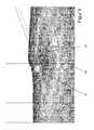
- FIG. 2a diagram is shown with a light distribution of the light emitted by the headlights 18 of the second vehicle 10 light on a vertical plane with activated high beam.
- the vertical planeis located at the distance of the taillights of a preceding vehicle 16.
- the light distribution caused by the headlights 18 of the second vehicle 10 at this distancecan be determined from a light distribution measured at a reference distance. Elements with the same structure or the same function have the same reference numerals.
- the brightness caused by the headlights 18 of the vehicle 10is greatest in the plane. As the distance to the center increases, the brightness of the light emitted by the headlights 18 decreases.
- Isolux linesare lines of equal brightness so that the brightness along such an isolux line is constant in the considered vertical plane. The closer the isolux lines are to each other, the greater the brightness change in this area.
- the blend area 22is limited in this embodiment by the isolux line 28.
- the isolux line with the value 0.1 luxis chosen as the limiting isolux line since it is assumed that glare of other road users can not be expected with a brightness of less than 0.1 lux.
- the preceding vehicle 16is located within the glare area 22, so that the driver of the preceding vehicle 16 is blinded by the light emitted by the headlights 18 of the second vehicle 10 and thus the traffic safety may be endangered.
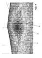
- FIG. 3a diagram is shown with a light distribution of the light emitted by the headlights 18 of the second vehicle 10 on a vertical plane with reduced light emission of the headlights 18 of the second vehicle 10.
- the vertical planeis arranged in front of the vehicle 10 at the distance of the taillights of the preceding vehicle 16.
- a light distribution of the radiated light from the headlights 18, for example, by a corresponding adjustment of a diaphragm rollerhas been generated in which the blend region 22 is formed significantly lower than in FIG. 2 and thus glare of the driver of the vehicle 16 in front and a possible risk to traffic safety are avoided.
- the Blend area 22is limited in this embodiment by the dazzling limit forming Isoluxline 30.
- FIG. 4a diagram is shown with a light distribution of the light emitted by the headlights 18 of the second vehicle 10 light on a vertical plane.
- the vertical planeis located at the distance of the headlights of an oncoming vehicle 32.
- the oncoming vehicle 32 in FIG. 4has the same distance to the second vehicle 10 as the preceding vehicle 16 to the second vehicle 10 in FIG.
- the driver of the oncoming vehicle 32is not blinded by the light emitted by the headlights 18 of the second vehicle 10, since the boundary 28 of the blind area 22 in the center of the second vehicle 10, ie to the center of the lane on which the second vehicle 10 is located, rises and falls sharply to the sides.
- knowing the precise light distribution of the light emitted by the headlights 18 of the second vehicle 10 and by knowing the position of the oncoming vehicle 32a better illumination of the area in front of the second vehicle 10 possible without the oncoming vehicle 32 is dazzled.
- the position of the oncoming vehicle 32can be determined, for example, with the aid of an image processing program for determining the distance to the vehicle 32 or for determining the position of the vehicle 32 during the processing of at least one image or image pair captured by the camera 12.
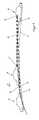
- FIG. 5is a side view of a schematically illustrated traffic situation with three vehicles 10, 34, 36 shown.
- the last-moving vehicle 10has a system for variably adjusting the light distribution.
- the two preceding vehicles 34, 36are at the in FIG. 5 illustrated traffic situation for the selection or for the adjustment of a glare-free light distribution emitted by the headlights 18 of the last position moving vehicle 10 light equally relevant.
- the glare boundary 20 of the blend region 22is not linear but has a curved course. This curved course of the dazzling limit 20 has an influence on the determination of the objects relevant for the selection of the optimal light distribution, such as the preceding vehicles 34, 36 when selecting the optimal light distribution of the light emitted by the headlights 18 of the vehicle 10. This is especially true the case when the vehicles 10, 34, 36 travel on a curved road 21.
- the relevant for the selection of the optimal light distribution objectsthose vehicles are classified as relevant, in which the dazzling limit 20 at the level of the taillights of the vehicle or above the taillights and thus at the level of, based on this embodiment, permissible dazzling limit or hits the vehicle above the permissible dazzling limit. If the dazzling limit 20 runs below the tail lights of a vehicle, there is no danger that the driver of this vehicle will be dazzled, so that such a vehicle is classified as irrelevant.
- the detection of the vehicles 34, 36 and the classification of the detected vehicles 34, 36 into relevant and irrelevant objectscan be done, for example, by means of corresponding image processing programs during the processing the image data of the images taken by the camera 12 of the vehicle 10 take place.
- the dashed lines 38 and 40show the line of sight of the camera 12 of the vehicle 10 to the tail lights 42, 44 of the vehicles 34, 36. Since in the embodiment in FIG. 5 the dazzling limit 20 on the taillights 42, 44 of both vehicles 34, 36, and thus on the permissible dazzling limits, both vehicles 34, 36 are classified as relevant objects and accordingly in the choice of the optimal light distribution of the headlights 18 of the vehicle 10th emitted light.
- FIG. 6shows a side view of a schematically illustrated traffic situation with three vehicles 10, 34, 36, wherein the last position traveling vehicle 10 has a system for variable adjustment of the light distribution.
- traffic situationis only relevant in the direction of travel P1 rear vehicle 34 of the two preceding vehicles 34, 36 for the selection or adjustment of a glare-free light distribution of the light emitted by the headlights 18 of the last position moving vehicle 10 light.
- the dazzling limit 20meets the front in the direction of travel P1 ahead vehicle 36 below the tail lights 44 of the front preceding vehicle 36, so that only the in Driving direction P1 seen rear vehicle 34 is classified as a relevant object and is taken into account in the selection or the setting of the optimal light distribution of the emitted light from the headlights 18 of the vehicle 10 accordingly.
- FIG. 7shows a side view of a schematically illustrated traffic situation with three vehicles 10, 34, 36, wherein the last position traveling vehicle 10 has a system for variable adjustment of the light distribution.
- the vehicle 36 in front of the two preceding vehicles 34, 36 in the direction of travel P1is relevant for the selection or adjustment of a glare-free light distribution of the light emitted by the headlights 18 of the last-moving vehicle 10.
- Unlike in FIG. 6meets in the embodiment of FIG.
- the forward vehicle 36 ahead in the direction of travel P1is significantly farther from the last vehicle 10 than the preceding vehicle 34 in the direction of travel P1
- the forward vehicle ahead 36is for the selection of a glare-free light distribution of the vehicle traveling through the headlights 18 of the last position 10 radiated light relevant.
- the distance between the two preceding vehicles 34, 36can be several hundred meters.
Landscapes
- Engineering & Computer Science (AREA)
- Mechanical Engineering (AREA)
- Lighting Device Outwards From Vehicle And Optical Signal (AREA)
Abstract
Translated fromGermanDescription
Translated fromGermanDie Erfindung betrifft ein Verfahren und eine Vorrichtung zum Ermitteln einer Lichtverteilung des durch mindestens einen Frontscheinwerfer eines Fahrzeugs abgestrahlten Lichts. Bei modernen Frontscheinwerfern ist es möglich, neben den bekannten Lichtverteilungen für Abblendlicht und Fernlicht zusätzliche an eine Verkehrssituation angepasste Lichtverteilungen zu erzeugen. Dadurch wird erreicht, dass auch Zwischenstufen der Lichtverteilung zwischen Abblendlicht und Fernlicht einstellbar sind, um den Bereich vor dem Fahrzeug optimal auszuleuchten. Dabei ist jedoch zu beachten, dass weder der vorausfahrende Verkehr noch der entgegenkommende Verkehr durch das abgestrahlte Licht behindert werden dürfen.The invention relates to a method and a device for determining a light distribution of the light emitted by at least one headlight of a vehicle. In modern headlamps, it is possible to generate in addition to the known light distributions for low beam and high beam additional adapted to a traffic situation light distributions. It is thereby achieved that intermediate stages of the light distribution between dipped beam and main beam can also be set in order to optimally illuminate the area in front of the vehicle. However, it should be noted that neither the preceding traffic nor the oncoming traffic may be obstructed by the radiated light.
Bei bekannten Lichtsteuervorgängen in Kraftfahrzeugen, insbesondere bei der Verwendung von einem Lichtassistenzsystem, werden nur bestimmte Parameter der Lichtverteilung beeinflusst. Insbesondere kann das Fernlicht an bzw. ausgeschaltet werden, ein gedimmtes Zuschalten des Fernlichts veranlasst werden oder mit Hilfe einer variablen Blende die obere Kante der Lichtverteilung bzw. einer durch das abgestrahlte Licht der Scheinwerfer erzeugte Hell-Dunkel-Grenze verändert werden. Dabei wird die konkret durch die Frontscheinwerfer erzeugte Lichtverteilung und der durch die Lichtverteilung erzeugte Verlauf der Hell-Dunkel-Grenze nicht berücksichtigt, sodass eine Lichtverteilung gewählt werden muss, die andere Verkehrsteilnehmer sicher nicht behindert jedoch eine geringere Ausleuchtung des Bereichs vor dem Fahrzeug bewirkt, als bei der konkreten Lage der anderen Verkehrsteilnehmer zur Hell-Dunkel-Grenze möglich wäre. Somit ist im Stand der Technik eine situationsadäquate Lichtsteuerung nicht für alle Verkehrssituationen möglich. Insbesondere wird die Ausleuchtung des Bereichs vor dem Fahrzeug oft unnötig stark eingeschränkt bzw. reduziert, um eine Gefährdung anderer Verkehrsteilnehmer mit den im Stand der Technik zur Verfügung stehenden Informationen sicher auszuschließen.In known light control processes in motor vehicles, in particular when using a light assistance system, only certain parameters of the light distribution are influenced. In particular, the high beam can be switched on or off, a dimmed connection of the high beam can be caused or using a variable aperture, the upper edge of the light distribution or a light-emitting boundary generated by the radiated light of the headlights are changed. In this case, the light distribution actually generated by the headlights and the course of the light-dark boundary generated by the light distribution is not taken into account, so that a light distribution must be selected, the other road users certainly not hindered but causes a lower illumination of the area in front of the vehicle than would be possible in the concrete location of the other road users to the cut-off line. Thus, in the prior art, a situation-adequate lighting control not possible for all traffic situations. In particular, the illumination of the area in front of the vehicle is often unnecessarily severely limited or reduced in order to reliably exclude a risk to other road users with the information available in the prior art.
Aus dem Dokument
Aus dem Dokument
Aus dem Dokument
Aus dem Dokument
Aus dem Dokument
Aufgabe der Erfindung ist es, ein Verfahren und eine Vorrichtung zur Auswahl einer geeigneten Lichtverteilung des durch mindestens einen Frontscheinwerfer eines Fahrzeugs abgestrahlten Lichts anzugeben, bei denen der Bereich vor dem Fahrzeug mit Hilfe des Frontscheinwerfers möglichst weiträumig ausgeleuchtet wird.The object of the invention is to specify a method and a device for selecting a suitable light distribution of the light emitted by at least one headlight of a vehicle, in which the area in front of the vehicle is illuminated as widely as possible with the aid of the headlight.
Diese Aufgabe wird durch ein Verfahren zur Auswahl einer geeigneten Lichtverteilung des durch mindestens einen Frontscheinwerfer eines Fahrzeugs abgestrahlten Lichts mit den Merkmalen des Patentanspruchs 1 sowie durch eine Vorrichtung mit den Merkmalen des nebengeordneten Vorrichtungsanspruchs gelöst. Vorteilhafte Weiterbildungen sind in den abhängigen Patentansprüchen angegeben.This object is achieved by a method for selecting a suitable light distribution of the light emitted by at least one headlight of a vehicle with the features of
Durch eine Berücksichtigung eines zumindest zweidimensionalen Verlaufs einer Blendungsgrenze für verschiedenen einstellbare Lichtverteilungen sowie der Position mindestens eines bei der Lichtverteilung des von dem mindestens einen Frontscheinwerfer abgestrahlten Lichts zu berücksichtigenden Objekts kann eine optimierte an die Situation angepasste Lichtabgabe durch das Fahrzeug erreicht werden, ohne unzulässig viel Licht auf das bei der Lichtabgabe zu berücksichtigende Objekt abzustrahlen. Ein solches bei der Lichtverteilung des von dem Frontscheinwerfer abgestrahlten Lichts zu berücksichtigenden Objekts kann beispielsweise ein vorausfahrendes oder entgegenkommendes Fahrzeug sein. Auf ein solches Fahrzeug darf nicht unzulässig viel Licht abgegeben werden, da der Fahrzeugführer des betreffenden Fahrzeuges sonst geblendet werden könnte. Dadurch erfolgt eine Gefährdung der Verkehrssicherheit.By taking into account an at least two-dimensional course of a dazzling limit for different adjustable light distributions and the position of at least one object to be considered in the light distribution of the light emitted by the at least one headlight, an optimized light output adapted to the situation by the vehicle can be achieved without unduly high levels of light to radiate to the object to be considered in the light output. Such an object to be considered in the light distribution of the light emitted by the headlight may be, for example, a vehicle ahead or oncoming. On such a vehicle may not be released inadmissible amount of light, as the Driver of the vehicle concerned could otherwise be blinded. This poses a threat to traffic safety.
Durch das erfindungsgemäße Verfahren und die Vorrichtung kann jedoch der Bereich vor dem Fahrzeug situationsoptimiert beleuchtet werden, sodass eine Lichtverteilung wählbar ist, die eine größtmögliche Ausleuchtung des Bereichs vor dem Fahrzeug ermöglicht und gerade nicht unzulässig viel Licht auf die zu berücksichtigenden Objekte abgibt. Somit erfolgt bei dem erfindungsgemäßen Verfahren und der erfindungsgemäßen Vorrichtung eine Situationserkennung der Verkehrssituation und die Bestimmung einer geeigneten Lichtverteilung, die dann mit Hilfe des mindestens einen Frontscheinwerfers des Fahrzeugs erzeugt wird. Ergibt die Überprüfung, dass die Blendungsgrenze eine zulässige Position zum relevanten Objekt hat, kann die Lichtverteilung zur Ausleuchtung des Bereichs vor dem Fahrzeug genutzt werden. Werden mindestens zwei mögliche Lichtverteilungen ermittelt, deren Blendungsgrenzen jeweils eine zulässige Position zu dem mindestens einen relevanten Objekt haben, wird vorzugsweise die ausgewählt, die den Bereich vor dem Fahrzeug größtmöglich ausleuchtet.By means of the method and the device according to the invention, however, the area in front of the vehicle can be illuminated in a situation-optimized manner, so that a light distribution can be selected which makes possible the greatest possible illumination of the area in front of the vehicle and does not emit inadmissibly much light on the objects to be considered. Thus, in the method according to the invention and the device according to the invention, a situation detection of the traffic situation and the determination of a suitable light distribution, which is then generated by means of the at least one headlight of the vehicle. If the check reveals that the glare limit has a permissible position relative to the relevant object, the light distribution can be used to illuminate the area in front of the vehicle. If at least two possible light distributions are determined whose glare boundaries each have an allowable position relative to the at least one relevant object, it is preferable to select the one that illuminates the area in front of the vehicle as far as possible.
Bei einer Weiterbildung der Erfindung wird die Position des Objekts relativ zur Blendungsgrenze mindestens einer der einstellbaren Lichtverteilungen ermittelt. Dadurch kann relativ einfach ermittelt werden, ob bei einer Einstellung der jeweiligen Lichtverteilung das Objekt im Blendbereich liegt und dadurch unzulässig viel Licht auf das Objekt abgestrahlt wird oder ob das Objekt bei der Einstellung dieser Lichtverteilung außerhalb des Blendbereichs liegt.In one development of the invention, the position of the object is determined relative to the glare boundary of at least one of the adjustable light distributions. As a result, it can be relatively easily determined whether the object lies in the aperture range when the respective light distribution is adjusted and as a result excessive light is emitted to the object or if the object is outside the aperture range when setting this light distribution.
Ferner ist es vorteilhaft, den Verlauf der Blendungsgrenzen für die mindestens zwei voneinander verschiedenen einstellbaren Lichtverteilungen in einem Speicherbereich gespeichert sind und aus diesem zum Ermitteln des Verlaufs einer Blendungsgrenze für die zumindest zwei voneinander verschieden einstellbaren Lichtverteilungen des mindestens einen Frontscheinwerfers erforderlichenfalls ausgelesen werden. Dadurch können die Daten zum Ermitteln des Verlaufs der Blendungsgrenze durch gespeicherte Daten hinterlegt und bei Bedarf ausgelesen oder aus gespeicherten Daten von Lichtverteilungen berechnet werden. Somit wird zumindest für ein Teil der möglichen Lichtverteilungen jeweils ein Verlauf einer zu dieser Lichtverteilung zugeordneten Blendungsgrenze bereitgestellt.Furthermore, it is advantageous for the course of the glare boundaries for the at least two mutually different adjustable light distributions to be stored in a memory area and, if necessary, read out for determining the course of a glare boundary for the at least two mutually differently adjustable light distributions of the at least one headlight. As a result, the data for determining the course of the glare limit can be stored by stored data and read out as required or calculated from stored data of light distributions. Thus, at least for a part of the possible light distributions, a course of a glare limit associated with this light distribution is provided in each case.
Der zweidimensionale Verlauf der Blendungsgrenze kann für mindestens eine Lichtverteilung, vorzugsweise für eine neben einer Abblendlichtverteilung und einer Fernlichtverteilung einstellbare Lichtverteilung, in einer Y-Z-Ebene des Fahrzeugkoordinatensystems des Fahrzeugs ermittelt werden. Die Y-Z-Ebene wird in X-Richtung vor dem Fahrzeug positioniert, vorzugsweise auf Höhe des Objekts. Dadurch kann der Verlauf der Blendungsgrenze und die Position des Objekts einfach überlagert werden und bestimmt werden, ob die Blendungsgrenze die erforderliche Lage, insbesondere einen maximalen oder minimalen erforderlichen Abstand, zum Objekt hat. Weiterhin kann der zweidimensionale Verlauf oder ein weiterer zweidimensionaler Verlauf der Blendungsgrenze in einer X-Z-Ebene des Fahrzeugkoordinatensystems des Fahrzeugs ermittelt werden. Dadurch kann der entfernungsabhängige Verlauf der Blendungsgrenze in X-Richtung ermittelt werden.The two-dimensional course of the glare boundary can be determined for at least one light distribution, preferably for a light distribution that can be set in addition to a low beam distribution and a high beam distribution, in a Y-Z plane of the vehicle coordinate system of the vehicle. The Y-Z plane is positioned in front of the vehicle in the X-direction, preferably at the height of the object. As a result, the course of the glare boundary and the position of the object can simply be superimposed and it can be determined whether the glare boundary has the required position, in particular a maximum or minimum required distance, from the object. Furthermore, the two-dimensional course or a further two-dimensional course of the glare boundary in an X-Z plane of the vehicle coordinate system of the vehicle can be determined. As a result, the distance-dependent course of the glare limit in the X direction can be determined.
Besonders vorteilhaft ist es, einen dreidimensionalen Verlauf der Blendungsgrenze für die mindestens zwei voneinander verschiedenen einstellbaren Lichtverteilungen zu ermitteln. Vorzugsweise wird für jede einstellbare Lichtverteilung eine dreidimensionale Blendungsgrenze ermittelt und zur Lichtsteuerung bereitgestellt, die von der Lichtverteilung für Abblendlicht und der Lichtverteilung für Fernlicht verschieden ist. Dabei sollte eine dreidimensionale Position des Objekts ermittelt werden. Dadurch kann sicher beurteilt werden, ob das Objekt in einem durch die Blendungsgrenze begrenzten Blendbereich liegt oder außerhalb des Blendbereichs.It is particularly advantageous to have a three-dimensional course of the glare boundary for the at least two mutually different adjustable ones Determine light distributions. Preferably, for each adjustable light distribution, a three-dimensional glare limit is determined and provided for light control, which is different from the light distribution for low beam and the light distribution for high beam. In this case, a three-dimensional position of the object should be determined. As a result, it can be judged with certainty whether the object lies within a glare area delimited by the glare boundary or outside the glare area.
Besonders vorteilhaft ist es, für jede mit Hilfe des mindestens einen Frontscheinwerfers einstellbare Lichtverteilung einen Verlauf der Blendungsgrenze dieser Lichtverteilung zu ermitteln. Dabei ist es nicht erforderlich, eine Blendungsgrenze für die bei Abblendlicht erzeugte geringste Lichtverteilung zu ermitteln.It is particularly advantageous to determine a progression of the glare limit of this light distribution for each light distribution that can be set using the at least one headlight. It is not necessary to determine a glare limit for the lowest light distribution generated at low beam.
Als Blendungsgrenze wird vorzugsweise eine Isoluxlinie, beispielsweise die Isoluxlinie mit dem Wert 0,1 Lux, genutzt. Es ist davon auszugehen, dass bei einer erzeugten Beleuchtungsstärke von kleiner gleich 0,1 Lux keine Blendung und somit keine Beeinträchtigung anderer Verkehrsteilnehmer durch das abgestrahlte Licht erfolgt.The dazzling limit used is preferably an isolux line, for example the isolux line with the value 0.1 lux. It is to be assumed that with a generated illuminance of less than or equal to 0.1 lux, no glare and thus no impairment of other road users by the radiated light takes place.
Die Lichtverteilung des durch den Frontscheinwerfer des Fahrzeugs abgestrahlten Lichts kann insbesondere durch eine Änderung der Stellung einer vor einer Lichtquelle angeordneten Blendenwelle, durch das Vorsehen einer verschiebbaren Blende, eines sogenannten Shutters, durch die Aktivierung einer Leuchtweitenregulierung, durch eine Leistungsänderung einer oder mehrerer Lichtquellen und/oder durch das Zu- bzw. Abschalten einer oder mehrerer Lichtquellen geändert werden.The light distribution of the light emitted by the front headlamp of the vehicle light can in particular by a change in the position of a arranged in front of a light source aperture, by providing a movable diaphragm, a so-called shutter, by activating a headlamp leveling, by a change in performance of one or more light sources and / or be changed by turning on or off one or more light sources.
Besonders vorteilhaft ist es, die sich im Bereich vor dem Fahrzeug befindenden Objekte in für die Lichtverteilung relevante und für die Lichtverteilung nicht relevante Objekte zu klassifizieren. Die Objekte, bei denen die Gefahr einer Blendung durch das durch die Frontscheinwerfer des Fahrzeugs abgestrahlte Licht besteht, werden dann als für die Lichtverteilung relevante Objekte klassifiziert. Dabei ist es vorteilhaft, nur die als relevant klassifizierten Objekte bei der Steuerung der Lichtverteilung zu berücksichtigen.It is particularly advantageous to classify the objects located in front of the vehicle in objects that are relevant for the light distribution and that are not relevant for the light distribution. The objects which are at risk of glare from the light emitted by the headlamps of the vehicle are then classified as objects relevant to the light distribution. It is advantageous to consider only the objects classified as relevant in the control of the light distribution.
Ferner ist es vorteilhaft, mit Hilfe einer Bilderfassungseinheit mindestens ein Bild mit Abbildungen von in einem Bereich vor dem Fahrzeug vorhandenen Objekten zu erfassen und dem Bild entsprechende Bilddaten zu erzeugen und diese zu verarbeiten. Die sich im Bereich vor dem Fahrzeug befindenden für die Lichtverteilung relevanten Objekte werden beim Verarbeiten der Bilddaten detektiert und klassifiziert. Als Bilderfassungseinheit eignet sich insbesondere eine bekannte Fahrzeugfrontkamera. Die Bilderfassungseinheit kann insbesondere eine monokulare Kamera, mehrere monokulare Kameras, ein Stereokamerasystem oder mehrere Stereokamerasysteme umfassen, wobei die einzelnen Kameras Bilddaten von Graustufenbildern oder Farbbildern erzeugen. Besonders vorteilhaft ist die Verwendung einer Kamera mit mindestens einem CMOS-Bilderfassungssensor, der vorzugsweise Graustufenbilder erzeugt. Beispielsweise hat die Bilderfassungseinheit einen Active-Pixel-Sensor als Bilderfassungssensor.Furthermore, it is advantageous with the aid of an image acquisition unit to capture at least one image with images of objects present in an area in front of the vehicle and to generate image data corresponding to the image and to process these. The objects that are relevant for the light distribution in the area in front of the vehicle are detected and classified during the processing of the image data. In particular, a known vehicle front camera is suitable as the image capture unit. In particular, the image acquisition unit may comprise a monocular camera, a plurality of monocular cameras, a stereo camera system or a plurality of stereo camera systems, wherein the individual cameras generate image data of grayscale images or color images. Particularly advantageous is the use of a camera with at least one CMOS image acquisition sensor, which preferably generates grayscale images. For example, the image capture unit has an active pixel sensor as an image capture sensor.
Ferner ist es vorteilhaft, solche Fahrzeuge als relevante Objekte zu klassifizieren, bei denen die Blendungsgrenze des Blendbereichs auf Höhe einer zulässigen Blendungsgrenze oder oberhalb einer zulässigen Blendungsgrenze auf das zu klassifizierende Fahrzeug trifft. Die zulässige Blendungsgrenze gibt die maximale Höhe an, bis zu der die Blendungsgrenze des Blendbereichs auf das zu klassifizierende Fahrzeug treffen darf, ohne dass der Fahrer des zu klassifizierenden Fahrzeugs durch das durch die Frontscheinwerfer des zweiten Fahrzeugs abgestrahlte Licht geblendet wird. Dadurch muss nur geprüft werden, ob die als relevant klassifizierten Objekte im Blendbereich oder außerhalb des Blendbereichs liegen. Die ermittelte Blendungsgrenze, die einen Blendbereich begrenzt, kann bei einer vorteilhaften Weiterbildung der Erfindung einen gekrümmten Verlauf haben. Jedoch ist diese Blendungsgrenze abhängig von der konkreten Ausbildung des Frontscheinwerfers und von der konkreten vom Frontscheinwerfer erzeugten Lichtverteilung.Furthermore, it is advantageous to classify such vehicles as relevant objects, in which the glare limit of the glare range coincides with the height of an admissible glare limit or above an admissible glare limit on the vehicle to be classified. The permissible dazzling limit indicates the maximum height up to which the dazzling limit of the dazzling area is allowed to strike the vehicle to be classified, without the driver of the vehicle to be classified being dazzled by the light emitted by the headlights of the second vehicle. As a result, it only has to be checked whether the objects classified as relevant lie in the glare area or outside the glare area. The determined glare limit, which limits a glare area, can have a curved course in an advantageous development of the invention. However, this glare limit is dependent on the specific design of the headlight and the specific light distribution generated by the headlight.
Bei einer vorteilhaften Weiterbildung wird geprüft, ob die durch die Frontscheinwerfer des zweiten Fahrzeugs in der Entfernung des relevanten vorausfahrenden Fahrzeugs erzeugte Blendungsgrenze unterhalb der zulässigen Blendungsgrenze des relevanten vorausfahrenden Fahrzeugs liegt. Erforderlichenfalls wird die Lichtverteilung des durch die Frontscheinwerfer des zweiten Fahrzeugs abgestrahlten Lichts geändert, so dass in der Entfernung des relevanten vorausfahrenden Fahrzeugs erzeugte Blendungsgrenze unterhalb der zulässigen Blendungsgrenze des relevanten vorausfahrenden Fahrzeugs liegt.In an advantageous development, it is checked whether the dazzling limit generated by the headlights of the second vehicle in the distance of the relevant preceding vehicle is below the permissible dazzling limit of the relevant preceding vehicle. If necessary, the light distribution of the light emitted by the headlights of the second vehicle is changed so that the dazzling limit generated in the distance of the relevant preceding vehicle is below the permissible dazzling limit of the relevant preceding vehicle.
Die Vorrichtung mit den Merkmalen des nebengeordneten Vorrichtungsanspruchs kann auf die gleiche Weise weitergebildet werden, wie für das erfindungsgemäße Verfahren angegeben. Insbesondere kann auch die Vorrichtung mit den in den abhängigen Patentansprüchen angegebenen Merkmalen oder entsprechenden Vorrichtungsmerkmalen weitergebildet werden.The device with the features of the independent device claim can be further developed in the same way as indicated for the method according to the invention. In particular, the device can also be developed with the features specified in the dependent claims or corresponding device features.
Weitere Merkmale und Vorteile der Erfindung ergeben sich aus der folgenden Beschreibung, welche in Verbindung mit den beigefügten Figuren die Erfindung anhand eines Ausführungsbeispiels näher erläutert.Further features and advantages of the invention will become apparent from the following description which, in conjunction with the accompanying figures, the invention using an exemplary embodiment explained in more detail.
Es zeigen:
Figur 1- eine schematische Seitenansicht einer Verkehrssituation mit zwei Fahrzeugen, wobei das hinter dem ersten Fahrzeug fah- rende zweite Fahrzeug ein System zur veränderlichen Ein- stellung der Lichtverteilung hat;
Figur 2- ein Diagramm mit einer Lichtverteilung des durch die Front- scheinwerfer eines Fahrzeuges abgestrahlten Lichts auf eine in der Entfernung zu einem vorausfahrenden Fahrzeug ange- ordnete senkrechte Ebene bei Fernlicht;
- Figur 3
- ein Diagramm mit einer Lichtverteilung des durch die Front- scheinwerfer des Fahrzeuges abgestrahlten Lichts auf eine in der Entfernung zu einem vorausfahrenden Fahrzeug angeord- nete senkrechte Ebene zu einem entgegenkommenden Fahr- zeug bei reduzierter Lichtabstrahlung der Frontscheinwerfer des Fahrzeugs;
- Figur 4
- ein Diagramm mit einer Lichtverteilung des durch die Front- scheinwerfer des Fahrzeuges abgestrahlten Lichts auf eine in der Entfernung zu einem entgegenkommenden Fahrzeug an- geordnete senkrechte Ebene;
Figur 5- eine Seitenansicht einer schematisch dargestellten Verkehrs- situation mit drei Fahrzeugen, wobei das an letzter Position fahrende Fahrzeug ein System zur veränderlichen Einstellung der Lichtverteilung hat und wobei die anderen beiden Fahr- zeuge für die Wahl einer blendungsfreien Lichtverteilung des durch die Frontscheinwerfer des an letzter Position fahrenden Fahrzeugs abgestrahlten Lichts gleichermaßen relevant sind;
- Figur 6
- eine Seitenansicht einer schematisch dargestellten Verkehrs- situation mit drei Fahrzeugen, wobei das an letzter Position fahrende Fahrzeug ein System zur veränderlichen Einstellung der Lichtverteilung hat und wobei das in Fahrtrichtung hinte- re Fahrzeug der anderen beiden Fahrzeug für die Wahl einer blendungsfreien Lichtverteilung des durch die Frontschein- werfer des an letzter Position fahrenden Fahrzeugs abge- strahlten Lichts relevant ist; und
- Figur 7
- eine Seitenansicht einer schematisch dargestellten Verkehrs- situation mit drei Fahrzeugen, wobei das an letzter Position fahrende Fahrzeug ein System zur veränderlichen Einstellung der Lichtverteilung hat und wobei das in Fahrtrichtung vor- dere Fahrzeug der anderen beiden Fahrzeuge für die Wahl ei- ner blendungsfreien Lichtverteilung des durch die Front- scheinwerfer des an letzter Position fahrenden Fahrzeugs ab- gestrahlten Lichts relevant ist.
- FIG. 1
- a schematic side view of a traffic situation with two vehicles, wherein the driving behind the first vehicle second vehicle has a system for variable adjustment of the light distribution;
- FIG. 2
- a diagram with a light distribution of the radiated by the headlights of a vehicle light to a arranged at a distance to a vehicle in front vertical plane at high beam;
- FIG. 3
- a diagram with a light distribution of the light emitted by the headlights of the vehicle light on a arranged in the distance to a preceding vehicle vertical plane to an oncoming vehicle with reduced light emission of the headlights of the vehicle;
- FIG. 4
- a diagram with a light distribution of the light emitted by the front headlights of the vehicle to a vertical plane disposed in the distance to an oncoming vehicle;
- FIG. 5
- a side view of a schematically illustrated traffic situation with three vehicles, the last vehicle driving has a system for variable adjustment of the light distribution and the other two vehicles for the election of a glare-free light distribution of driving through the headlights of the last position Vehicle of radiated light are equally relevant;
- FIG. 6
- a side view of a schematically illustrated traffic situation with three vehicles, the vehicle driving at the last position has a system for variable adjustment of the light distribution and the rearward in the direction of travel vehicle of the other two vehicle for the choice of a glare-free light distribution of the front - is relevant of the light emitted at the last position vehicle radiating light relevant; and
- FIG. 7
- a side view of a schematically illustrated traffic situation with three vehicles, the moving vehicle in last position has a system for variable adjustment of the light distribution and wherein the front in the direction of travel vehicle of the other two vehicles for the election of a glare-free light distribution of the headlights of the light emitted at the last position are relevant.
In
Die Steuereinheit 14 ist weiterhin über eine zweite Datenleitung 15 mit den Lichtsteuermodulen 17 verbunden, wobei den Frontscheinwerfern 18 des Fahrzeugs 10 beim Ausführungsbeispiel nach
Hierzu werden mit Hilfe eines Bildverarbeitungsprogramms in einem von der Kamera 12 aufgenommen Bild die Rückleuchten 24 des vorausfahrenden Fahrzeugs 16 detektiert und die Position des vorausfahrenden Fahrzeuges 16 ermittelt. Ferner wird die Entfernung zwischen dem Fahrzeug 10 und dem vorausfahrenden Fahrzeug 16 ermittelt. Der durch die Frontscheinwerfer 18 bei einer Lichtabgabe erzeugter Blendbereich 22 wird so weit in Richtung einer Fahrbahn 21 abgesenkt, dass die obere Grenze des Blendbereichs 22 auf Höhe einer zulässigen Blendungsgrenze auf das vorausfahrenden Fahrzeug 16 trifft und somit der Fahrer des vorherfahrenden Fahrzeugs 16 nicht geblendet wird. Die zulässige Blendungsgrenze ist durch die Strichlinie 23 angedeutet. Der Blendbereich 22 gibt denjenigen Bereich an, in dem der Fahrer des vorausfahrenden Fahrzeugs 16 durch das von den Frontscheinwerfern 18 des zweiten Fahrzeugs 10 abgestrahlten Lichts geblendet wird oder geblendet werden kann. Die obere Grenze des Blendbereichs 22 wird auch als horizontale Hell-Dunkel-Grenze oder Blendungsgrenze bezeichnet. Die Blendungsgrenze ist im Ausführungsbeispiel schematisch durch die Linie 20 dargestellt. Als Blendungsgrenze 20 wird im vorliegenden Ausführungsbeispiel die 0,1 Lux Isoluxlinie im Raum definiert, d. h. die dreidimensionale Isolux-Lichtverteilung der Beleuchtungsstärke 0,1 Lux. Bei anderen Ausführungsbeispielen können auch andere Beleuchtungsstärken zum Festlegen der Blendungsgrenze 20 gewählt werden. Die zulässige Blendungsgrenze 23 gibt die maximale Höhe an, in der die Blendungsgrenze 20 auf das vorausfahrende Fahrzeug 16 treffen darf, ohne dass der Fahrer des vorausfahrenden Fahrzeugs 16 durch das durch die Frontscheinwerfer 18 des zweiten Fahrzeugs 10 abgestrahlte Licht geblendet wird. Die zulässige Blendungsgrenze 23 ist so gewählt, dass die Blendungsgrenze 22 der von den Frontscheinwerfern 18 des zweiten Fahrzeugs 10 unterhalb der Position des Kopfes des Fahrers des vorausfahrenden Fahrzeugs 16 bzw. der Positionen der Rückspiegel des vorausfahrenden Fahrzeugs 16 verläuft. Die für das vorausfahrende Fahrzeug 16 zulässige Blendungsgrenze 23 kann insbesondere auch abhängig vom Fahrzeugtyp des vorausfahrenden Fahrzeugs 16 ermittelt werden. Ferner kann die zulässige Blendungsgrenze 23 zum Beispiel durch gesetzliche Vorschriften vorgegeben sein. Im vorliegenden Ausführungsbeispiel wird zur Vereinfachung im Folgenden davon ausgegangen, dass die zulässige Blendungsgrenze 23 jeweils auf Höhe der Rückleuchten eines Fahrzeugs liegt. In der Praxis sind auch anderen Verläufe der zulässigen Blendungsgrenze 23 möglich.For this purpose, the
Alternativ zur beschriebenen Möglichkeit, bei der die Steuereinheit 14 den Lichtsteuermodulen 17 eine gewünschte Lichtverteilung vorgibt, kann die Steuereinheit 14 die Lichtquellen und/oder Aktoren des mindestens einen Frontscheinwerfers 18 direkt ansteuern oder entsprechende Steuersignale zum Lichtsteuermodul 17 übertragen.As an alternative to the described possibility, in which the
Das Erzeugen einer gewünschten Lichtverteilung und eine gewünschte Verschiebung der Blendungsgrenze 20 kann je nach Modell des Fahrzeugs 10 und je nach der verwendeten Technik der Frontscheinwerfer 18 auf unterschiedliche Art und Weise erfolgen. Insbesondere kann die Lichtverteilung durch das Drehen einer vor einer Lichtquelle angeordneten Blendenwelle, durch das Absenken eines Shutters, durch die Aktivierung einer Leuchtweitenregulierung, durch eine Leistungsänderung einer oder mehrerer Lichtquellen und/oder das Zu- bzw. Abschalten einer oder mehrerer Lichtquellen geändert bzw. die Blendungsgrenze 20 verschoben werden. Mit Hilfe der Blendenwelle können verschiedene Lichtfiguren erzeugt werden, die sowohl die unterschiedlichen Formen der Lichtverteilung als auch verschiedene horizontale Hell-Dunkel-Grenzen bzw. Blendungsgrenzen 20 repräsentieren. Solche Lichtfiguren sind beispielsweise aus der Schrift
Um zum einen eine Blendung anderer Verkehrsteilnehmer zu vermeiden und zum anderen aber auch den vor dem zweiten Fahrzeug 10 liegenden Raum optimal auszuleuchten, ist es wichtig die genaue Lichtverteilung des von den Frontscheinwerfern des zweiten Fahrzeugs 10 abgestrahlten Lichts und somit auch die genaue Form und Lage des Blendbereichs 22 zu kennen und entsprechend bei der Steuerung der Frontscheinwerfer 18 des zweiten Fahrzeugs 10 zu berücksichtigen. Insbesondere ist es wichtig, die Lichtverteilung für die unterschiedlichen Stellungen der Blendenwalze zu kennen.In order to avoid the dazzling of other road users on the one hand and to optimally illuminate the other lying in front of the
In
Der Blendbereich 22 wird in diesem Ausführungsbeispiel durch die Isoluxlinie 28 begrenzt. Vorteilhafterweise wird als begrenzende Isoluxlinie die Isoluxlinie mit dem Wert 0,1 Lux gewählt, da davon ausgegangen wird, dass bei einer Helligkeit von kleiner 0,1 Lux keine Blendung anderer Verkehrsteilnehmer zu erwarten ist. Das vorausfahrende Fahrzeug 16 befindet sich innerhalb des Blendbereichs 22, so dass Fahrer des vorausfahrenden Fahrzeugs 16 durch das von den Frontscheinwerfern 18 des zweiten Fahrzeugs 10 abgestrahlte Licht geblendet wird und somit die Verkehrsicherheit gefährdet sein kann.The
In
In
In
Bei der Ermittlung der für die Auswahl der optimalen Lichtverteilung relevanten Objekte werden diejenigen Fahrzeuge als relevant eingestuft, bei denen die Blendungsgrenze 20 auf Höhe der Rückleuchten des Fahrzeuges oder oberhalb der Rückleuchten und somit auf Höhe der, diesem Ausführungsbeispiel zu Grunde gelegten, zulässigen Blendungsgrenze bzw. oberhalb der zulässigen Blendungsgrenze auf das Fahrzeug trifft. Verläuft die Blendungsgrenze 20 unterhalb der Rückleuchten eines Fahrzeuges besteht keine Gefahr, dass der Fahrer dieses Fahrzeuges geblendet wird, sodass ein solches Fahrzeug als irrelevant klassifiziert wird. Die Detektion der Fahrzeuge 34, 36 und die Klassifizierung der detektierten Fahrzeuge 34, 36 in relevante und nicht relevante Objekte kann beispielweise mit Hilfe von entsprechenden Bildverarbeitungsprogrammen bei der Verarbeitung der Bilddaten der von der Kamera 12 des Fahrzeugs 10 aufgenommen Bildern erfolgen. Die Strichlinien 38 und 40 zeigen die Sichtlinien der Kamera 12 des Fahrzeug 10 zu den Rückleuchten 42, 44 der Fahrzeuge 34, 36. Da im Ausführungsbeispiel in
Obwohl das in Fahrtrichtung P1 vordere vorausfahrende Fahrzeug 36 deutlich weiter vom letzten Fahrzeug 10 entfernt ist als das in Fahrtrichtung P1 hintere vorausfahrende Fahrzeug 34, ist das vordere vorausfahrende Fahrzeug 36 für die Wahl einer blendungsfreien Lichtverteilung des durch die Frontscheinwerfer 18 des an letzter Position fahrenden Fahrzeugs 10 abgestrahlten Lichts relevant. Dabei kann die Entfernung zwischen den beiden vorausfahrenden Fahrzeugen 34, 36 mehrere hundert Meter betragen. Würde also, beispielweise durch eine unzureichende Kenntnis der Lichtverteilung des durch die Frontscheinwerfer 18 des letzten Fahrzeugs 10 abgestrahlten Lichts, das in Fahrtrichtung P1 hintere vorausfahrende Fahrzeug 34 als relevant klassifiziert und die Lichtverteilung entsprechend angesteuert, so würde der Bereich vor dem Fahrzeug 10 nicht optimal, d. h. geringer als möglich, ausgeleuchtet werden. Die Sichtweite des Fahrzeugführers des Fahrzeugs 10 würde unnötig reduziert sein.Although the
Claims (15)
Translated fromGermanbei dem die Position mindestens eines bei der Lichtverteilung des von dem mindestens einen Frontscheinwerfer (18) abgestrahlten Lichts zu berücksichtigenden Objekts (16, 32, 34, 36) im Bereich vor dem Fahrzeug (10) ermittelt wird,
ein zumindest zweidimensionaler Verlauf einer Blendungsgrenze (20) für mindestens eine einstellbare Lichtverteilung des mindestens einen Frontscheinwerfers (18) ermittelt wird, und
bei dem überprüft wird, ob die für diese Lichtverteilung ermittelte Blendungsgrenze (20, 28, 30) eine zulässige Lage zur ermittelten Position des Objekts (16, 32, 34, 36) hat.Method for determining a suitable light distribution of the light emitted by at least one headlight of a vehicle,
in which the position of at least one object (16, 32, 34, 36) to be considered in the light distribution of the light emitted by the at least one headlight (18) is determined in the area in front of the vehicle (10),
an at least two-dimensional course of a dazzling limit (20) for at least one adjustable light distribution of the at least one headlight (18) is determined, and
in which it is checked whether the glare limit (20, 28, 30) determined for this light distribution has a permissible position relative to the determined position of the object (16, 32, 34, 36).
mit einer Bilderfassungseinheit (12), die mindestens ein Bild mit Abbildungen von in einem Bereich vor dem Fahrzeug (10) vorhandenen Objekten erfasst wird und dem Bild entsprechende Bilddaten erzeugt,
mit einer Verarbeitungseinheit (14),
die sich im Bereich vor dem Fahrzeug (10) befindenden für die Lichtverteilung relevanten Objekte (16 ,32, 34, 36) detektiert und klassifiziert,
die Position mindestens eines bei der Lichtverteilung des von dem mindestens einen Frontscheinwerfer (18) abgestrahlten Lichts zu berücksichtigenden Objekts (16, 32, 34, 36) im Bereich vor dem Fahrzeug (10) ermittelt,
die einen zumindest zweidimensionalen Verlauf einer Blendungsgrenze (20) für mindestens eine einstellbare Lichtverteilung des mindestens einen Frontscheinwerfers (18) ermittelt, und
die überprüft, ob die für die Lichtverteilung ermittelte Blendungsgrenze (20, 28, 30) eine zulässige Lage zur ermittelten Position des Objekts (16, 32, 34, 36) hat.Devices for determining a suitable light distribution of the light emitted by at least one headlight of a vehicle,
with an image acquisition unit (12) which captures at least one image with images of objects present in an area in front of the vehicle (10) and generates image data corresponding to the image,
with a processing unit (14),
the objects (16, 32, 34, 36), which are relevant for the distribution of light in the area in front of the vehicle (10), are detected and classified,
determines the position of at least one object (16, 32, 34, 36) to be considered in the light distribution of the light emitted by the at least one headlight (18) in the region in front of the vehicle (10),
determining an at least two-dimensional course of a glare boundary (20) for at least one adjustable light distribution of the at least one headlight (18), and
which checks whether the glare limit (20, 28, 30) determined for the light distribution has an allowable position relative to the determined position of the object (16, 32, 34, 36).
Applications Claiming Priority (1)
| Application Number | Priority Date | Filing Date | Title |
|---|---|---|---|
| DE102008034166ADE102008034166A1 (en) | 2008-07-22 | 2008-07-22 | Method and device for Euting a suitable light distribution of the light emitted by at least one headlight of a vehicle light |
Publications (2)
| Publication Number | Publication Date |
|---|---|
| EP2147823A1true EP2147823A1 (en) | 2010-01-27 |
| EP2147823B1 EP2147823B1 (en) | 2012-09-05 |
Family
ID=41129276
Family Applications (1)
| Application Number | Title | Priority Date | Filing Date |
|---|---|---|---|
| EP20090166129ActiveEP2147823B1 (en) | 2008-07-22 | 2009-07-22 | Method and device for determining a suitable light distribution of the light emitted by at least one headlamp of a vehicle |
Country Status (2)
| Country | Link |
|---|---|
| EP (1) | EP2147823B1 (en) |
| DE (1) | DE102008034166A1 (en) |
Cited By (5)
| Publication number | Priority date | Publication date | Assignee | Title |
|---|---|---|---|---|
| DE102010029149A1 (en)* | 2010-05-20 | 2011-11-24 | Robert Bosch Gmbh | Method and control unit for plausibility checking of a headlight range test value of a light cone of a vehicle headlight |
| WO2012116931A1 (en)* | 2011-03-02 | 2012-09-07 | Robert Bosch Gmbh | Method and control unit for influencing an illumination scene in front of a vehicle |
| EP2596990A1 (en)* | 2011-11-22 | 2013-05-29 | Hella KGaA Hueck & Co. | Method and controller for controlling main headlights with adjustable light/dark limit for preventing glare from objects |
| WO2013102526A1 (en)* | 2012-01-03 | 2013-07-11 | Robert Bosch Gmbh | Method and control device for adapting an upper boundary of a headlight beam |
| WO2017000007A1 (en)* | 2015-06-29 | 2017-01-05 | Zkw Group Gmbh | Control device for a lighting unit in a motor vehicle, and method for controlling a lighting unit of said type |
Families Citing this family (2)
| Publication number | Priority date | Publication date | Assignee | Title |
|---|---|---|---|---|
| DE102010021944A1 (en)* | 2010-05-28 | 2011-12-01 | Hella Kgaa Hueck & Co. | Device for forecasting road arrangement in front of vehicle, particularly motor vehicle, comprises interface for reading information about position of headlights or rear lights of vehicle |
| DE102012200040A1 (en)* | 2012-01-03 | 2013-07-04 | Robert Bosch Gmbh | Method and control unit for adjusting an upper headlight beam boundary of a headlight cone |
Citations (10)
| Publication number | Priority date | Publication date | Assignee | Title |
|---|---|---|---|---|
| EP0121457B1 (en) | 1983-03-07 | 1986-09-17 | Cibie Projecteurs | Lamp reflectors for motor vehicles produced by injection moulding of two components of polyalkyleneterephthalate |
| US5645338A (en) | 1993-08-03 | 1997-07-08 | Koito Manufacturing Co., Ltd. | Light distribution control device for vehicular headlamp |
| DE19822142A1 (en) | 1998-05-16 | 1999-11-18 | Bosch Gmbh Robert | Generation of light bundle on a road vehicle for sensing obstructions on a road |
| US20040052083A1 (en)* | 2002-09-12 | 2004-03-18 | Yoshinao Daicho | Vehicle headlamp apparatus |
| EP0935728B1 (en) | 1997-09-06 | 2004-05-26 | Hella KG Hueck & Co. | Headlight for vehicles |
| US7156542B2 (en) | 2002-12-13 | 2007-01-02 | Ford Global Technologies, Llc | Vehicle headlight system having digital beam-forming optics |
| US7195379B2 (en) | 2005-01-03 | 2007-03-27 | Ford Global Technologies, Llc | Anti-blinding system for a vehicle |
| WO2008037388A2 (en)* | 2006-09-27 | 2008-04-03 | Volkswagen Aktiengesellschaft | Headlight arrangement for a vehicle and method for controlling a headlight arrangement |
| EP1923262A1 (en)* | 2006-11-17 | 2008-05-21 | Valeo Vision | Method for automatically adjusting the light beam of a headlight device |
| EP1964717A2 (en)* | 2007-03-02 | 2008-09-03 | Hella KGaA Hueck & Co. | Method and device for controlling the light emission of a vehicle dependent on the inclination of a roadway ahead |
Family Cites Families (8)
| Publication number | Priority date | Publication date | Assignee | Title |
|---|---|---|---|---|
| JPH10175478A (en)* | 1996-12-18 | 1998-06-30 | Koito Mfg Co Ltd | Lighting fixture device for vehicle |
| US6049171A (en)* | 1998-09-18 | 2000-04-11 | Gentex Corporation | Continuously variable headlamp control |
| DE19950504A1 (en)* | 1999-10-20 | 2001-05-10 | Porsche Ag | Method and device for controlling the light distribution of a headlight arrangement of a vehicle |
| US6774367B2 (en)* | 2002-08-14 | 2004-08-10 | Ford Global Technologies, Llc | Active night vision system for vehicles employing anti-blinding scheme |
| US7541743B2 (en)* | 2002-12-13 | 2009-06-02 | Ford Global Technologies, Llc | Adaptive vehicle communication controlled lighting system |
| JP4258385B2 (en)* | 2004-01-14 | 2009-04-30 | 株式会社デンソー | Road surface reflection detector |
| EP1722159A4 (en)* | 2004-02-25 | 2008-01-23 | Hitachi Ltd | VEHICLE HEADLIGHTS AND VEHICLE SUPPLY SUPPORT |
| JP4624257B2 (en)* | 2005-12-28 | 2011-02-02 | 株式会社小糸製作所 | Vehicle lighting |
- 2008
- 2008-07-22DEDE102008034166Apatent/DE102008034166A1/ennot_activeWithdrawn
- 2009
- 2009-07-22EPEP20090166129patent/EP2147823B1/enactiveActive
Patent Citations (10)
| Publication number | Priority date | Publication date | Assignee | Title |
|---|---|---|---|---|
| EP0121457B1 (en) | 1983-03-07 | 1986-09-17 | Cibie Projecteurs | Lamp reflectors for motor vehicles produced by injection moulding of two components of polyalkyleneterephthalate |
| US5645338A (en) | 1993-08-03 | 1997-07-08 | Koito Manufacturing Co., Ltd. | Light distribution control device for vehicular headlamp |
| EP0935728B1 (en) | 1997-09-06 | 2004-05-26 | Hella KG Hueck & Co. | Headlight for vehicles |
| DE19822142A1 (en) | 1998-05-16 | 1999-11-18 | Bosch Gmbh Robert | Generation of light bundle on a road vehicle for sensing obstructions on a road |
| US20040052083A1 (en)* | 2002-09-12 | 2004-03-18 | Yoshinao Daicho | Vehicle headlamp apparatus |
| US7156542B2 (en) | 2002-12-13 | 2007-01-02 | Ford Global Technologies, Llc | Vehicle headlight system having digital beam-forming optics |
| US7195379B2 (en) | 2005-01-03 | 2007-03-27 | Ford Global Technologies, Llc | Anti-blinding system for a vehicle |
| WO2008037388A2 (en)* | 2006-09-27 | 2008-04-03 | Volkswagen Aktiengesellschaft | Headlight arrangement for a vehicle and method for controlling a headlight arrangement |
| EP1923262A1 (en)* | 2006-11-17 | 2008-05-21 | Valeo Vision | Method for automatically adjusting the light beam of a headlight device |
| EP1964717A2 (en)* | 2007-03-02 | 2008-09-03 | Hella KGaA Hueck & Co. | Method and device for controlling the light emission of a vehicle dependent on the inclination of a roadway ahead |
Cited By (15)
| Publication number | Priority date | Publication date | Assignee | Title |
|---|---|---|---|---|
| DE102010029149B4 (en)* | 2010-05-20 | 2012-04-05 | Robert Bosch Gmbh | Method and control unit for plausibility checking of a headlight range test value of a light cone of a vehicle headlight |
| DE102010029149A1 (en)* | 2010-05-20 | 2011-11-24 | Robert Bosch Gmbh | Method and control unit for plausibility checking of a headlight range test value of a light cone of a vehicle headlight |
| US9589080B2 (en) | 2010-05-20 | 2017-03-07 | Robert Bosch Gmbh | Method and control unit for validating an illumination-range test value of a light cone of a vehicle headlight |
| US20130158960A1 (en)* | 2010-05-20 | 2013-06-20 | Tobias Rentschler | Method and control unit for validating an illumination-range test value of a light cone of a vehicle headlight |
| CN103402819A (en)* | 2011-03-02 | 2013-11-20 | 罗伯特·博世有限公司 | Method and control unit for influencing an illumination scene in front of a vehicle |
| WO2012116931A1 (en)* | 2011-03-02 | 2012-09-07 | Robert Bosch Gmbh | Method and control unit for influencing an illumination scene in front of a vehicle |
| US9481292B2 (en) | 2011-03-02 | 2016-11-01 | Robert Bosch Gmbh | Method and control unit for influencing a lighting scene ahead of a vehicle |
| CN103402819B (en)* | 2011-03-02 | 2016-04-20 | 罗伯特·博世有限公司 | Method and control device for influencing a lighting scene in front of a vehicle |
| EP2596990A1 (en)* | 2011-11-22 | 2013-05-29 | Hella KGaA Hueck & Co. | Method and controller for controlling main headlights with adjustable light/dark limit for preventing glare from objects |
| CN103129449A (en)* | 2011-11-22 | 2013-06-05 | 黑拉许克联合股份有限公司 | Method and controller for controlling main headlights for preventing glare from objects |
| WO2013102525A1 (en)* | 2012-01-03 | 2013-07-11 | Robert Bosch Gmbh | Method and control device for adapting an upper boundary of a headlight beam |
| WO2013102526A1 (en)* | 2012-01-03 | 2013-07-11 | Robert Bosch Gmbh | Method and control device for adapting an upper boundary of a headlight beam |
| US9637047B2 (en) | 2012-01-03 | 2017-05-02 | Robert Bosch Gmbh | Method and control unit for adapting an upper headlight beam boundary of a light cone |
| WO2017000007A1 (en)* | 2015-06-29 | 2017-01-05 | Zkw Group Gmbh | Control device for a lighting unit in a motor vehicle, and method for controlling a lighting unit of said type |
| CN107921906A (en)* | 2015-06-29 | 2018-04-17 | Zkw集团有限责任公司 | The control device of the lighting apparatus of motor vehicle and the method for this lighting apparatus of control |
Also Published As
| Publication number | Publication date |
|---|---|
| EP2147823B1 (en) | 2012-09-05 |
| DE102008034166A1 (en) | 2010-01-28 |
Similar Documents
| Publication | Publication Date | Title |
|---|---|---|
| DE102008011699B4 (en) | Method for determining a property for the operation of a motor vehicle and correspondingly designed motor vehicle | |
| EP2508391B1 (en) | Method and device for controlling the light emission of a front headlamp of a vehicle | |
| DE102008025458B4 (en) | Method and device for calibrating a horizontal cut-off line generated by a headlight of a vehicle | |
| DE102007040042B4 (en) | System for generating a light beam in the apron of a motor vehicle | |
| DE102008025459B4 (en) | Method and device for calibrating a vertical cut-off line generated by a headlight of a vehicle | |
| DE102018204424B3 (en) | Method for calibrating a position of a matrix headlight of a motor vehicle, control device and motor vehicle | |
| EP3402694B1 (en) | Headlight system and method for making available a cornering light function | |
| EP2127945B1 (en) | Methods and device for controlling the light emission of a vehicle | |
| EP2147823B1 (en) | Method and device for determining a suitable light distribution of the light emitted by at least one headlamp of a vehicle | |
| EP2204771A1 (en) | Method and device for determining a change in the inclination of a camera of a vehicle | |
| DE112011103104T5 (en) | Headlamp device and intended light intensity control method | |
| EP1964717B1 (en) | Method and device for controlling the light emission of a vehicle dependent on the inclination of a roadway ahead | |
| DE102010048100B4 (en) | Method and device for controlling the headlights of a vehicle | |
| EP2130718B1 (en) | Method and device for controlling the light emission of at least one front headlamp of a vehicle | |
| DE102014108239A1 (en) | Method for adaptively controlling a high-resolution headlight system | |
| WO2015022115A1 (en) | Method for controlling a headlight arrangement for a vehicle and such a headlight arrangement | |
| DE102021106713A1 (en) | System and method relating to an adaptive vehicle headlamp | |
| WO2015090699A1 (en) | Method and device for determining a beam width alignment of a headlight | |
| DE102010048689A1 (en) | Method for adjusting and/or calibrating headlight of motor vehicle, involves comparing determined global position at bright-dark-limit with reference position, and calibrating and/or adjusting headlight with determined deviation | |
| EP3140159B1 (en) | Method for operating a driver assistance system of a motor vehicle, driver assistance system, and motor vehicle | |
| EP2123512B1 (en) | Control device to control and/or to command a vertical cut-off line | |
| DE102021115179B4 (en) | Headlight and headlight system for a motor vehicle | |
| WO2019034306A1 (en) | HEADLIGHT FOR ONE VEHICLE | |
| DE102017205768A1 (en) | Headlight system for a vehicle | |
| DE202019106099U1 (en) | Motor vehicle headlights with a lighting device |
Legal Events
| Date | Code | Title | Description |
|---|---|---|---|
| PUAI | Public reference made under article 153(3) epc to a published international application that has entered the european phase | Free format text:ORIGINAL CODE: 0009012 | |
| AK | Designated contracting states | Kind code of ref document:A1 Designated state(s):AT BE BG CH CY CZ DE DK EE ES FI FR GB GR HR HU IE IS IT LI LT LU LV MC MK MT NL NO PL PT RO SE SI SK SM TR | |
| AX | Request for extension of the european patent | Extension state:AL BA RS | |
| 17P | Request for examination filed | Effective date:20100720 | |
| 17Q | First examination report despatched | Effective date:20100813 | |
| GRAP | Despatch of communication of intention to grant a patent | Free format text:ORIGINAL CODE: EPIDOSNIGR1 | |
| GRAS | Grant fee paid | Free format text:ORIGINAL CODE: EPIDOSNIGR3 | |
| GRAA | (expected) grant | Free format text:ORIGINAL CODE: 0009210 | |
| AK | Designated contracting states | Kind code of ref document:B1 Designated state(s):AT BE BG CH CY CZ DE DK EE ES FI FR GB GR HR HU IE IS IT LI LT LU LV MC MK MT NL NO PL PT RO SE SI SK SM TR | |
| REG | Reference to a national code | Ref country code:GB Ref legal event code:FG4D Free format text:NOT ENGLISH | |
| REG | Reference to a national code | Ref country code:CH Ref legal event code:EP | |
| REG | Reference to a national code | Ref country code:AT Ref legal event code:REF Ref document number:573947 Country of ref document:AT Kind code of ref document:T Effective date:20120915 | |
| REG | Reference to a national code | Ref country code:IE Ref legal event code:FG4D Free format text:LANGUAGE OF EP DOCUMENT: GERMAN | |
| REG | Reference to a national code | Ref country code:DE Ref legal event code:R096 Ref document number:502009004602 Country of ref document:DE Effective date:20121031 | |
| REG | Reference to a national code | Ref country code:NL Ref legal event code:VDEP Effective date:20120905 | |
| PG25 | Lapsed in a contracting state [announced via postgrant information from national office to epo] | Ref country code:LT Free format text:LAPSE BECAUSE OF FAILURE TO SUBMIT A TRANSLATION OF THE DESCRIPTION OR TO PAY THE FEE WITHIN THE PRESCRIBED TIME-LIMIT Effective date:20120905 Ref country code:CY Free format text:LAPSE BECAUSE OF FAILURE TO SUBMIT A TRANSLATION OF THE DESCRIPTION OR TO PAY THE FEE WITHIN THE PRESCRIBED TIME-LIMIT Effective date:20120905 Ref country code:NO Free format text:LAPSE BECAUSE OF FAILURE TO SUBMIT A TRANSLATION OF THE DESCRIPTION OR TO PAY THE FEE WITHIN THE PRESCRIBED TIME-LIMIT Effective date:20121205 Ref country code:FI Free format text:LAPSE BECAUSE OF FAILURE TO SUBMIT A TRANSLATION OF THE DESCRIPTION OR TO PAY THE FEE WITHIN THE PRESCRIBED TIME-LIMIT Effective date:20120905 Ref country code:HR Free format text:LAPSE BECAUSE OF FAILURE TO SUBMIT A TRANSLATION OF THE DESCRIPTION OR TO PAY THE FEE WITHIN THE PRESCRIBED TIME-LIMIT Effective date:20120905 | |
| REG | Reference to a national code | Ref country code:LT Ref legal event code:MG4D Effective date:20120905 | |
| PG25 | Lapsed in a contracting state [announced via postgrant information from national office to epo] | Ref country code:SI Free format text:LAPSE BECAUSE OF FAILURE TO SUBMIT A TRANSLATION OF THE DESCRIPTION OR TO PAY THE FEE WITHIN THE PRESCRIBED TIME-LIMIT Effective date:20120905 Ref country code:GR Free format text:LAPSE BECAUSE OF FAILURE TO SUBMIT A TRANSLATION OF THE DESCRIPTION OR TO PAY THE FEE WITHIN THE PRESCRIBED TIME-LIMIT Effective date:20121206 Ref country code:LV Free format text:LAPSE BECAUSE OF FAILURE TO SUBMIT A TRANSLATION OF THE DESCRIPTION OR TO PAY THE FEE WITHIN THE PRESCRIBED TIME-LIMIT Effective date:20120905 Ref country code:SE Free format text:LAPSE BECAUSE OF FAILURE TO SUBMIT A TRANSLATION OF THE DESCRIPTION OR TO PAY THE FEE WITHIN THE PRESCRIBED TIME-LIMIT Effective date:20120905 | |
| PG25 | Lapsed in a contracting state [announced via postgrant information from national office to epo] | Ref country code:ES Free format text:LAPSE BECAUSE OF FAILURE TO SUBMIT A TRANSLATION OF THE DESCRIPTION OR TO PAY THE FEE WITHIN THE PRESCRIBED TIME-LIMIT Effective date:20121216 Ref country code:IS Free format text:LAPSE BECAUSE OF FAILURE TO SUBMIT A TRANSLATION OF THE DESCRIPTION OR TO PAY THE FEE WITHIN THE PRESCRIBED TIME-LIMIT Effective date:20130105 Ref country code:EE Free format text:LAPSE BECAUSE OF FAILURE TO SUBMIT A TRANSLATION OF THE DESCRIPTION OR TO PAY THE FEE WITHIN THE PRESCRIBED TIME-LIMIT Effective date:20120905 Ref country code:NL Free format text:LAPSE BECAUSE OF FAILURE TO SUBMIT A TRANSLATION OF THE DESCRIPTION OR TO PAY THE FEE WITHIN THE PRESCRIBED TIME-LIMIT Effective date:20120905 Ref country code:CZ Free format text:LAPSE BECAUSE OF FAILURE TO SUBMIT A TRANSLATION OF THE DESCRIPTION OR TO PAY THE FEE WITHIN THE PRESCRIBED TIME-LIMIT Effective date:20120905 Ref country code:RO Free format text:LAPSE BECAUSE OF FAILURE TO SUBMIT A TRANSLATION OF THE DESCRIPTION OR TO PAY THE FEE WITHIN THE PRESCRIBED TIME-LIMIT Effective date:20120905 | |
| PG25 | Lapsed in a contracting state [announced via postgrant information from national office to epo] | Ref country code:SK Free format text:LAPSE BECAUSE OF FAILURE TO SUBMIT A TRANSLATION OF THE DESCRIPTION OR TO PAY THE FEE WITHIN THE PRESCRIBED TIME-LIMIT Effective date:20120905 Ref country code:PT Free format text:LAPSE BECAUSE OF FAILURE TO SUBMIT A TRANSLATION OF THE DESCRIPTION OR TO PAY THE FEE WITHIN THE PRESCRIBED TIME-LIMIT Effective date:20130107 Ref country code:PL Free format text:LAPSE BECAUSE OF FAILURE TO SUBMIT A TRANSLATION OF THE DESCRIPTION OR TO PAY THE FEE WITHIN THE PRESCRIBED TIME-LIMIT Effective date:20120905 | |
| PLBE | No opposition filed within time limit | Free format text:ORIGINAL CODE: 0009261 | |
| STAA | Information on the status of an ep patent application or granted ep patent | Free format text:STATUS: NO OPPOSITION FILED WITHIN TIME LIMIT | |
| PG25 | Lapsed in a contracting state [announced via postgrant information from national office to epo] | Ref country code:BG Free format text:LAPSE BECAUSE OF FAILURE TO SUBMIT A TRANSLATION OF THE DESCRIPTION OR TO PAY THE FEE WITHIN THE PRESCRIBED TIME-LIMIT Effective date:20121205 Ref country code:DK Free format text:LAPSE BECAUSE OF FAILURE TO SUBMIT A TRANSLATION OF THE DESCRIPTION OR TO PAY THE FEE WITHIN THE PRESCRIBED TIME-LIMIT Effective date:20120905 | |
| 26N | No opposition filed | Effective date:20130606 | |
| PG25 | Lapsed in a contracting state [announced via postgrant information from national office to epo] | Ref country code:IT Free format text:LAPSE BECAUSE OF FAILURE TO SUBMIT A TRANSLATION OF THE DESCRIPTION OR TO PAY THE FEE WITHIN THE PRESCRIBED TIME-LIMIT Effective date:20120905 | |
| REG | Reference to a national code | Ref country code:DE Ref legal event code:R097 Ref document number:502009004602 Country of ref document:DE Effective date:20130606 | |
| BERE | Be: lapsed | Owner name:HELLA KGAA HUECK & CO. Effective date:20130731 | |
| PG25 | Lapsed in a contracting state [announced via postgrant information from national office to epo] | Ref country code:MC Free format text:LAPSE BECAUSE OF FAILURE TO SUBMIT A TRANSLATION OF THE DESCRIPTION OR TO PAY THE FEE WITHIN THE PRESCRIBED TIME-LIMIT Effective date:20120905 | |
| REG | Reference to a national code | Ref country code:CH Ref legal event code:PL | |
| REG | Reference to a national code | Ref country code:IE Ref legal event code:MM4A | |
| PG25 | Lapsed in a contracting state [announced via postgrant information from national office to epo] | Ref country code:CH Free format text:LAPSE BECAUSE OF NON-PAYMENT OF DUE FEES Effective date:20130731 Ref country code:LI Free format text:LAPSE BECAUSE OF NON-PAYMENT OF DUE FEES Effective date:20130731 Ref country code:BE Free format text:LAPSE BECAUSE OF NON-PAYMENT OF DUE FEES Effective date:20130731 | |
| PG25 | Lapsed in a contracting state [announced via postgrant information from national office to epo] | Ref country code:IE Free format text:LAPSE BECAUSE OF NON-PAYMENT OF DUE FEES Effective date:20130722 | |
| REG | Reference to a national code | Ref country code:DE Ref legal event code:R082 Ref document number:502009004602 Country of ref document:DE Representative=s name:SCHAUMBURG & PARTNER PATENTANWAELTE GBR, DE Ref country code:DE Ref legal event code:R082 Ref document number:502009004602 Country of ref document:DE Representative=s name:SCHAUMBURG UND PARTNER PATENTANWAELTE MBB, DE | |
| PG25 | Lapsed in a contracting state [announced via postgrant information from national office to epo] | Ref country code:SM Free format text:LAPSE BECAUSE OF FAILURE TO SUBMIT A TRANSLATION OF THE DESCRIPTION OR TO PAY THE FEE WITHIN THE PRESCRIBED TIME-LIMIT Effective date:20120905 | |
| PG25 | Lapsed in a contracting state [announced via postgrant information from national office to epo] | Ref country code:TR Free format text:LAPSE BECAUSE OF FAILURE TO SUBMIT A TRANSLATION OF THE DESCRIPTION OR TO PAY THE FEE WITHIN THE PRESCRIBED TIME-LIMIT Effective date:20120905 Ref country code:MT Free format text:LAPSE BECAUSE OF FAILURE TO SUBMIT A TRANSLATION OF THE DESCRIPTION OR TO PAY THE FEE WITHIN THE PRESCRIBED TIME-LIMIT Effective date:20120905 | |
| PG25 | Lapsed in a contracting state [announced via postgrant information from national office to epo] | Ref country code:LU Free format text:LAPSE BECAUSE OF NON-PAYMENT OF DUE FEES Effective date:20130722 Ref country code:HU Free format text:LAPSE BECAUSE OF FAILURE TO SUBMIT A TRANSLATION OF THE DESCRIPTION OR TO PAY THE FEE WITHIN THE PRESCRIBED TIME-LIMIT; INVALID AB INITIO Effective date:20090722 Ref country code:MK Free format text:LAPSE BECAUSE OF FAILURE TO SUBMIT A TRANSLATION OF THE DESCRIPTION OR TO PAY THE FEE WITHIN THE PRESCRIBED TIME-LIMIT Effective date:20120905 | |
| REG | Reference to a national code | Ref country code:AT Ref legal event code:MM01 Ref document number:573947 Country of ref document:AT Kind code of ref document:T Effective date:20140722 | |
| PG25 | Lapsed in a contracting state [announced via postgrant information from national office to epo] | Ref country code:AT Free format text:LAPSE BECAUSE OF NON-PAYMENT OF DUE FEES Effective date:20140722 | |
| REG | Reference to a national code | Ref country code:FR Ref legal event code:PLFP Year of fee payment:8 | |
| REG | Reference to a national code | Ref country code:FR Ref legal event code:PLFP Year of fee payment:9 | |
| REG | Reference to a national code | Ref country code:DE Ref legal event code:R081 Ref document number:502009004602 Country of ref document:DE Owner name:HELLA GMBH CO. KGAA, DE Free format text:FORMER OWNER: HELLA KGAA HUECK CO., 59557 LIPPSTADT, DE Ref country code:DE Ref legal event code:R082 Ref document number:502009004602 Country of ref document:DE Representative=s name:SCHAUMBURG UND PARTNER PATENTANWAELTE MBB, DE Ref country code:DE Ref legal event code:R081 Ref document number:502009004602 Country of ref document:DE Owner name:HELLA GMBH & CO. KGAA, DE Free format text:FORMER OWNER: HELLA KGAA HUECK & CO., 59557 LIPPSTADT, DE | |
| REG | Reference to a national code | Ref country code:FR Ref legal event code:PLFP Year of fee payment:10 | |
| PGFP | Annual fee paid to national office [announced via postgrant information from national office to epo] | Ref country code:DE Payment date:20240604 Year of fee payment:16 | |
| PGFP | Annual fee paid to national office [announced via postgrant information from national office to epo] | Ref country code:GB Payment date:20250619 Year of fee payment:17 | |
| PGFP | Annual fee paid to national office [announced via postgrant information from national office to epo] | Ref country code:FR Payment date:20250623 Year of fee payment:17 |