EP2147567B1 - Voice and position localization - Google Patents
Voice and position localizationDownload PDFInfo
- Publication number
- EP2147567B1 EP2147567B1EP08749602.2AEP08749602AEP2147567B1EP 2147567 B1EP2147567 B1EP 2147567B1EP 08749602 AEP08749602 AEP 08749602AEP 2147567 B1EP2147567 B1EP 2147567B1
- Authority
- EP
- European Patent Office
- Prior art keywords
- ultrasonic
- audible
- frequencies
- sensor
- input
- Prior art date
- Legal status (The legal status is an assumption and is not a legal conclusion. Google has not performed a legal analysis and makes no representation as to the accuracy of the status listed.)
- Not-in-force
Links
Images


Classifications
- G—PHYSICS
- G01—MEASURING; TESTING
- G01S—RADIO DIRECTION-FINDING; RADIO NAVIGATION; DETERMINING DISTANCE OR VELOCITY BY USE OF RADIO WAVES; LOCATING OR PRESENCE-DETECTING BY USE OF THE REFLECTION OR RERADIATION OF RADIO WAVES; ANALOGOUS ARRANGEMENTS USING OTHER WAVES
- G01S11/00—Systems for determining distance or velocity not using reflection or reradiation
- G01S11/14—Systems for determining distance or velocity not using reflection or reradiation using ultrasonic, sonic, or infrasonic waves
- H—ELECTRICITY
- H04—ELECTRIC COMMUNICATION TECHNIQUE
- H04R—LOUDSPEAKERS, MICROPHONES, GRAMOPHONE PICK-UPS OR LIKE ACOUSTIC ELECTROMECHANICAL TRANSDUCERS; DEAF-AID SETS; PUBLIC ADDRESS SYSTEMS
- H04R1/00—Details of transducers, loudspeakers or microphones
- H04R1/20—Arrangements for obtaining desired frequency or directional characteristics
- H04R1/22—Arrangements for obtaining desired frequency or directional characteristics for obtaining desired frequency characteristic only
- H04R1/24—Structural combinations of separate transducers or of two parts of the same transducer and responsive respectively to two or more frequency ranges
- G—PHYSICS
- G06—COMPUTING OR CALCULATING; COUNTING
- G06F—ELECTRIC DIGITAL DATA PROCESSING
- G06F3/00—Input arrangements for transferring data to be processed into a form capable of being handled by the computer; Output arrangements for transferring data from processing unit to output unit, e.g. interface arrangements
- G06F3/01—Input arrangements or combined input and output arrangements for interaction between user and computer
- G06F3/03—Arrangements for converting the position or the displacement of a member into a coded form
- G06F3/033—Pointing devices displaced or positioned by the user, e.g. mice, trackballs, pens or joysticks; Accessories therefor
- G06F3/0346—Pointing devices displaced or positioned by the user, e.g. mice, trackballs, pens or joysticks; Accessories therefor with detection of the device orientation or free movement in a 3D space, e.g. 3D mice, 6-DOF [six degrees of freedom] pointers using gyroscopes, accelerometers or tilt-sensors
- G—PHYSICS
- G06—COMPUTING OR CALCULATING; COUNTING
- G06F—ELECTRIC DIGITAL DATA PROCESSING
- G06F3/00—Input arrangements for transferring data to be processed into a form capable of being handled by the computer; Output arrangements for transferring data from processing unit to output unit, e.g. interface arrangements
- G06F3/01—Input arrangements or combined input and output arrangements for interaction between user and computer
- G06F3/03—Arrangements for converting the position or the displacement of a member into a coded form
- G06F3/033—Pointing devices displaced or positioned by the user, e.g. mice, trackballs, pens or joysticks; Accessories therefor
- G06F3/0354—Pointing devices displaced or positioned by the user, e.g. mice, trackballs, pens or joysticks; Accessories therefor with detection of 2D relative movements between the device, or an operating part thereof, and a plane or surface, e.g. 2D mice, trackballs, pens or pucks
- G06F3/03545—Pens or stylus
- G—PHYSICS
- G06—COMPUTING OR CALCULATING; COUNTING
- G06F—ELECTRIC DIGITAL DATA PROCESSING
- G06F3/00—Input arrangements for transferring data to be processed into a form capable of being handled by the computer; Output arrangements for transferring data from processing unit to output unit, e.g. interface arrangements
- G06F3/01—Input arrangements or combined input and output arrangements for interaction between user and computer
- G06F3/03—Arrangements for converting the position or the displacement of a member into a coded form
- G06F3/041—Digitisers, e.g. for touch screens or touch pads, characterised by the transducing means
- G06F3/043—Digitisers, e.g. for touch screens or touch pads, characterised by the transducing means using propagating acoustic waves
- H—ELECTRICITY
- H04—ELECTRIC COMMUNICATION TECHNIQUE
- H04R—LOUDSPEAKERS, MICROPHONES, GRAMOPHONE PICK-UPS OR LIKE ACOUSTIC ELECTROMECHANICAL TRANSDUCERS; DEAF-AID SETS; PUBLIC ADDRESS SYSTEMS
- H04R3/00—Circuits for transducers, loudspeakers or microphones
- H04R3/12—Circuits for transducers, loudspeakers or microphones for distributing signals to two or more loudspeakers
- H04R3/14—Cross-over networks
Definitions
- the present inventionin some embodiments thereof, relates to providing audio applications and ultrasonic applications through the same microphones and, more particularly, but not exclusively, to carrying out simultaneous noise cancellation and stylus localization on the sonic and ultrasonic signals respectively.
- noise cancellationis in teleconference equipment.
- a voice of a speakeris localized by a microphone, noise arising from directions other than the speaker is attenuated, producing better quality transmission of the speaker's voice.
- Other examples of noise cancellationuse special microphones which subtract peripheral noise from a voice entering the front of the microphone.
- a popular microphone typeis a condenser microphone.
- Stylus localization using sound wavesrequires a more accurate localization than that achieved by audio wavelengths, in addition to the fact that an ultrasound stylus does not annoy users with audible noise. Better localization can be achieved by using shorter audio wavelengths, that is, ultrasonic wavelengths, but it is noted that condenser microphones do not have good sensitivity to ultrasonic frequencies. On the other hand, ultrasonic sensors usually have poor sensitivity in the sonic band.
- WO2004010275which describes position information input into an information processing system in, e.g. a mobile communication terminal.
- the systemcomprises a plurality of microphones located at known microphone positions and connected to processing circuitry capable of interpreting sound signals from the microphones.
- a sound signalis received from each microphone, the signals originating from an acoustic wave emanating from an acoustic sound source located at a first position.
- a respective difference in distance between the sound source at said first position and respective microphoneis then calculated, followed by a calculation, using a geometric model, of an estimate of said first position, said estimate being position information intended for use in the information processing system.
- UK Patent GB2388077describes a stylus which contains an ultrasound transmitter for transmitting position signals and a second transmitter for transmitting a timing signal which may be infrared.
- a detector assemblyhas position signal receivers (condenser microphones) and a timing signal receiver on a base appliance which also contains hardware and firmware to enable the stylus or an eraser to be tracked on writing surfaces, such as whiteboards, blackboards, flip charts or tablet PCs. It also has a detachable personality module which contains user-related interactions and/or displays, such as push buttons and LEDs and/or LCDs. The personality module contains logic for communications and stand-alone functions.
- the detector assemblyalso has a detachable nameplate. The detector may be used without an external processor to record writing in local storage, for subsequent transfer and display. Alternatively, it may be used with an external display unit.
- US Patent 6577299describes a wireless pen apparatus for producing signals representative of writing by a user, including: a wireless pen; a removable cap on the pen; and, when the cap is removed from the pen and placed at a reference position, communicating wave energy between at least one location on the pen and at least one location on the cap for determining the position of the at least one location on the pen with respect to the reference position of the cap, and for producing signals that depend on the determined position of the at least one location on the pen.
- US Published Patent Application No. 2003/071798describes a system for generating digital ink from triangulation data of a stylus comprises an electromagnetic radiation source capable to emit electromagnetic pulses; a first and a second ultrasound detector separated from each other by a known distance; a timer coupled to the radiation source, the first detector, and the second detector, and capable to measure a first elapsed time between emission of an electromagnetic pulse from the radiation source and detection of an ultrasound wave at the first detector, and further capable to measure a second elapsed time between emission of the electromagnetic pulse from the radiation source and detection of an ultrasound wave at the second detector; and a triangulation engine coupled to the timer and the radiation source, the engine capable to instruct the source to emit a plurality of radiation pulses, to triangulate the position of an ultrasound transponder over time based on the first elapsed time, the second elapsed time and the known distance between detectors, and to generate characters based on the triangulation data.
- US Published Patent Application No. 2006/077188discloses a device and method for inputting characters or drawings on a mobile terminal using a virtual screen
- the mobile terminalincludes an electronic pen, a virtual screen generator, a position detector for detecting the electronic pen position, and a character recognition algorithm for recognizing a trail as a character.
- the mobile terminaldetects the originating position of the signal and its trail. The mobile terminal recognizes the detected trail as a character and generates a virtual screen with the recognized character.
- JP A 10293643teaches a position detection system which can detect the position of a microphone and an input device containing the microphone by addition of a simple circuit.
- WO 00/21203Ateaches a method of communicating with an electronic device, comprising: providing a computer having an audible sound receiving and generating sub-system including a microphone; transmitting from a source at least one ultrasonic acoustic signal encoded with information to the computer and receiving a signal from the microphone to be detected by the computer.
- the ultrasonic signalis described as being below 50KHz.
- the same sensorsare used for picking up both sonic and ultrasonic signals, and output of the sensors provides Input to electronics suitable for processing both types of signals.
- MEMS microphonesuch as made by Knowles Acoustics.
- one embodiment of the inventionuses two filters, one filter for ultrasonic pickup, and one filter for sonic pickup. Filtered signals are processed by a processor configured to implement an audio application, an ultrasonic application, or both.
- apparatusconfigured for processing of both audible and ultrasonic sound inputs, including a sensor with a frequency response spanning both audible and ultrasonic frequencies, and processing electronics configured to separate the audible and ultrasonic input frequencies for independent use.
- the frequency response of the sensoris substantially different in the audible frequencies and in the ultrasonic frequencies. According to some embodiments of the invention, the difference is more than 40dB. According to some embodiments of the invention, the processing electronics is configured to amplify a lower one of a response of the sensor to the audible frequencies and a response of the sensor to the ultrasonic frequencies.
- the processing electronicsincludes independent processing parts for independently processing the separated frequencies.
- the processing electronicsincludes a first filter configured to filter audible frequencies and a second filter configured to filter ultrasonic frequencies. According to the invention, the processing electronics further includes a multiplexer for switching between the separated frequencies. According to some embodiments of the invention, the processing electronics includes a Digital Signal Processor (DSP).
- DSPDigital Signal Processor
- the processing electronicsis configured for simultaneous processing of audible and ultrasonic output of the sensor.
- the apparatusincludes two or more sensors. According to some embodiments of the invention, a same sensor is used for picking up the audible and the ultrasonic sound inputs.
- the sensorsare MEMS microphones.
- the processing electronicsis configured for localization of at least one source of the ultrasonic sound input. According to some embodiments of the invention, the processing electronics is configured for localization of at least one source of the audible sound input.
- the processing electronicsis configured to localize an ultrasonic sound source in three dimensions by comparing the ultrasonic output of more than one sensor.
- the processing electronicsis configured to track movement of the ultrasonic sound source. According to some embodiments of the invention, the processing electronics is configured to produce output corresponding to the tracking.
- the apparatusis included in a cell phone.
- the apparatusis further configured for equipment monitoring. According to some embodiments of the invention, the apparatus is further configured to indicate location of faulty equipment.
- the apparatusis further configured to measure distance.
- the apparatusfurther includes an ultrasonic sound source.
- the apparatusis included as part of a distance determination unit in a focusing unit of a camera.
- the apparatusis further configured to detect animals emitting ultrasonic sounds. According to some embodiments of the invention, the apparatus is further configured to localize animals emitting ultrasonic sounds.
- the apparatusis further configured to simultaneously record sound and perform ultrasonic sound source localization.
- the ultrasonic sound source localizationfurther includes producing input to a writing application.
- the apparatusis configured to perform ultrasonic sound source localization for more than one ultrasonic sound source.
- ultrasonic sound source localizationfurther includes producing input to more than one writing application.
- the apparatusis further configured to indicate location of tags emitting ultrasonic sound. According to some embodiments of the invention, the apparatus is further configured to send a signal to the tags in order to cause the tags to emit ultrasonic sound.
- a systemincluding the apparatus and a stylus configured to emit ultrasonic sound.
- the systemfurther includes a touch-screen, in which placing a tip of the stylus on the touch-screen produces output corresponding to a location of the tip of the stylus on the touch-screen, and moving the tip of the stylus along the touch-screen surface produces output corresponding to the movement of the tip of the stylus along the touch-screen surface.
- a systemincluding the apparatus and a pointing device configured to emit ultrasonic sound.
- the apparatusincludes three sensors and produces a localization of the pointing device in three dimensions.
- the pointing deviceis a mouse.
- apparatusconfigured for processing of both audible and ultrasonic sound inputs, including a sensor with a frequency response spanning both audible and ultrasonic frequencies, and processing electronics configured to process each one of the audible and ultrasonic input frequencies independently.
- a method for processing of both audible and ultrasonic sound inputsusing a sensor with a frequency response spanning both audible and ultrasonic input frequencies for input of audible and ultrasonic sound inputs, and processing electronics for separating the audible and ultrasonic input frequencies for independent use.
- the sensorincludes more than one sensor, and further including calibrating the response to input from at least one of the sensors.
- the processing electronicsis configured for simultaneous processing of audible and ultrasonic frequencies.
- a method for processing of both audible and ultrasonic sound inputsusing a sensor with a frequency response spanning both audible and ultrasonic input frequencies for input of audible and ultrasonic sound inputs, and processing each one of the audible and ultrasonic input frequencies independently.
- the processing each one of the audible and ultrasonic input frequenciesindependently includes amplifying one of the audible and ultrasonic input frequencies differently from the other.
- Implementation of the method and/or system of embodiments of the inventioncan involve performing or completing selected tasks manually, automatically, or a combination thereof. Moreover, according to actual instrumentation and equipment of embodiments of the method and/or system of the invention, several selected tasks could be implemented by hardware, by software or by firmware or by a combination thereof using an operating system.
- a data processorsuch as a computing platform for executing a plurality of instructions.
- the data processorincludes a volatile memory for storing instructions and/or data and/or a non-volatile storage, for example, a magnetic hard-disk and/or removable media, for storing instructions and/or data.
- a network connectionis provided as well.
- a display and/or a user input devicesuch as a keyboard or mouse are optionally provided as well.
- the present inventionin some embodiments thereof, relates to providing audio applications and ultrasonic applications through the same microphones and, more particularly, but not exclusively, to carrying out simultaneous noise cancellation and stylus localization on the sonic and ultrasonic signals respectively.
- Example sensorsare MEMS microphones, which have a broad frequency response, including audio frequencies and ultrasonic frequencies.
- one embodiment of the inventionuses two filters, one filter for ultrasonic pickup, and one filter for sonic pickup. Filtered signals are processed by a processor configured to implement an audio application, an ultrasonic application, or both.
- sensorin all its grammatical forms is used throughout the present specification and claims interchangeably with the term “microphone” and its corresponding grammatical forms.
- sensorstransform vibrations into electronic signals, and any of them can serve as sensors in the invention.
- a non-limiting list of such sensorsincludes ceramic sensors, piezoelectric sensors, PVDF (Polyvinylidene Flouride) sensors, electro-static sensors, and so on.
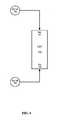
- Fig. 1is a simplified block diagram of an example, using a microphone which picks up both audio and ultrasonic signals.
- the example of Fig. 1comprises a microphone 105, a filter 101, a sonic signal processing unit 106, and an ultrasonic signal processing unit 107.
- the microphone 105is sensitive to both sonic and ultrasonic sound frequencies.
- a non-limiting example of such a microphoneis a MEMS microphone such as described above.
- the microphone 105is connected to, and produces signals which are input to, a filter 101.
- the filter 101sends output of audible frequency signals 102 to the sonic signal processing unit 106, and output of ultrasonic frequency signals 103 to the ultrasonic signal processing unit 107.
- the sonic signal processing unit 106optionally implements audible, or voice, applications.
- the ultrasonic signal processing unit 107optionally implements ultrasonic applications.
- a response of the microphone 105may be substantially different in the audible range and in the ultrasonic range. When such is the case, amplifying the lower of the responses is performed.
- the amplificationis performed before the audible and ultrasound frequencies are separated, by an amplifier configured to perform different amplification for the different frequency ranges. In other embodiments of the invention the amplification is performed after the audible and ultrasound frequencies are separated.
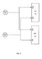
- FIG. 2is a simplified block diagram of an alternative example, using two microphones which pick up both audio and ultrasonic signals.
- the example of Fig. 1comprises two microphones 105, two filters 101, a sonic signal processing unit 106, and an ultrasonic signal processing unit 107.
- the two microphones 105are as described above, with reference to Fig. 1 .
- Each of the two microphones 105is connected to, and produces signals which are input to, a corresponding one of the two filters 101.
- Each one of the filters 101sends output of audible frequency signals 102 to the sonic signal processing unit 106, and output of ultrasonic frequency signals 103 to the ultrasonic signal processing unit 107.
- the sonic signal processing unit 106optionally accepts audible frequency signals 102 from the two microphones 105, and optionally implements audible, or voice, applications.
- a non-limiting example of such an audible applicationis a voice compression/transmission application.
- Another non-limiting example of such an audible applicationis a noise cancellation application.
- Another non-limiting example of such an audible applicationis a speaker localization application, or an audible noise source localization application.
- the ultrasonic signal processing unit 107optionally accepts the ultrasonic frequency signals 103 from two microphones, and optionally implements ultrasonic applications.
- ultrasonic applicationsare a stylus localization application and a stylus tracking application.
- the two microphones 105may not have equal responses to input sound, whether sonic or ultrasonic. Some embodiments of the invention perform measurement and subsequent calibration of the response of the microphones 105 relative to each other, thereby enabling better accuracy to applications than if the microphones 105 are not calibrated.
- each of the microphones 105may not itself provide a linear response to input sound, whether sonic or ultrasonic. Some embodiments of the invention perform measurement and subsequent calibration of the response of the microphones 105, thereby enabling better accuracy to applications than of the microphones 105 are not calibrated.
- the microphones 105provide a substantially linear input signal, making the calibration process simple or even unnecessary.
- calibrationis also performed for reasons other than linearity.
- additional causes for calibrationare: different phase response of the microphones; different spatial response of the microphones such as different response for sound received from different directions; and difference in mechanical environment of each of the microphones.
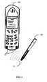
- FIG. 3is a simplified image of a system combining voice pickup and stylus localization using the example of Fig. 1 .
- the system of Fig. 3comprises a cell phone 200 comprising two microphones 105 and a stylus 205.
- the two microphones 105are as described above, with reference to Fig. 1 .
- At least one of the microphones 105serves the cell phone 200 for sound pickup for performing a telephone conversation. Typically one microphone is enough for picking up a telephone conversation. Optionally, both of the microphones 105 are used.
- the two microphones 105also serve as ultrasonic pickups for an ultrasound transmitter (not shown) comprised in the stylus 205.
- the ultrasound transmitter (not shown)emits ultrasonic sound 210 which is picked up by the two microphones 105.
- the cell phone 200comprises an embodiment of the invention of Fig. 1 , and a stylus localization application such as described in the above-mentioned PCT Patent Application No. IB 2008/050946 of Altman et al.
- An alternative of the system of Fig. 3additionally comprises a noise cancellation system, which uses both of the microphones 105 in order to emphasize a source of a voice from a speaker's direction, and de-emphasizes noise from other directions.
- An embodiment comprising three or more microphonesis optionally used for three dimensional localization of the ultrasound transmitter (not shown) comprised in the stylus 205.
- an alternative of the system of Fig. 3comprises an array of microphones.
- a DSP(not shown) receives signals from the array, improving accuracy of the localization compared to two microphones.
- the localization of a sound sourceoptionally provides a distance from the invention to the sound source.
- the localization of the sound sourceis optionally in two dimensions, defining a two-dimensional surface in which the sound source is located.
- two microphonesoptionally estimate a DOA (Direction of Arrival) of the ultrasonic sound and/or the audible sound.
- DOADirection of Arrival
- An alternative embodiment of the inventioncomprises a synchronizing mechanism, optionally using a different technology to communicate synchronizing information to an embodiment of the invention.
- the communicationis optionally done, by way of a non-limiting example, by wired communication, such as an electric connection, or by wireless communication, such as an IR and/or RF communication.
- the synchronizing mechanismoptionally enables measuring a distance to each of the sensors, thereby enabling triangulation in order to localize the sound source.
- the localizationis optionally in three dimensions, such as providing a direction and a distance from the invention to the sound source, or distance along three axes.
- Fig. 4is a simplified block diagram of another example.
- the example of Fig. 4comprises two microphones 105 and a DSP 130.
- the microphones 105are as described above with reference to Fig. 1 .
- the microphones 105are each connected to an input 131 132 of the DSP 130.
- the DSP 130comprises an analog to digital converter with enough speed and dynamic range to convert both sonic and ultrasonic signals to digital.
- an optional amplifieramplifies the microphone signals before A/D (analog to digital) conversion.
- A/D conversion of the embodiment of Fig. 4occurs in the DSP 130, therefore the amplification optionally occurs on the DSP 130, before the A/D conversion.
- the filter 101 of Fig. 1optionally implements amplification.
- the DSP 130optionally performs filtering of incoming signals, in the digital domain, to a sonic frequency range or an ultrasonic frequency range.
- the DSP 130subsequently optionally implements processing of the filtered signals for a sonic application or an ultrasonic application.
- the DSP 130optionally implements processing of one of the above-mentioned applications, and subsequently implements processing the other of the above-mentioned applications.
- the DSP 130optionally switches between the sonic and ultrasonic ranges periodically, and implements both applications one after another at a rapid rate.
- the DSP 130optionally performs rate conversion on at least one of the frequency bands, audible and sonic, before processing signals of the rate converted frequency band.
- the DSP 130optionally processes sonic and ultrasonic applications at the same time.
- FIG. 5is a simplified block diagram of a embodiment of the invention.
- the example embodiment of Fig. 5comprises two microphones 105, two analog sonic filters 110, two analog ultrasonic filters 115, two multiplexers 120, and a Digital Signal Processor (DSP) 125.
- DSPDigital Signal Processor
- the two microphonesmay be similar to the microphones 105 of Fig. 1A, being sensitive to both sonic and ultrasonic signals.
- the microphones 105are each connected to one of the analog sonic filters 110 and one of the analog ultrasonic filters 115, and provide input to the analog filters 110 115.
- the analog filters 110 115are each connected to one of the multiplexers 120.
- the multiplexers 120provide output to the DSP 125.
- the DSP 125provides control signals to the multiplexers 120, selecting which of the sonic or the ultrasonic signals the multiplexers 120 should provide as output at any time.
- the microphones 105pick up sound signals and provide the sound signals as input to the analog filters 110 115.
- the sound signalsmay be audio signals, ultrasonic signals, and both audio and ultrasonic simultaneously.
- the analog ultrasonic filters 115pass through ultrasonic signals.
- the analog sonic filters 110pass through sonic signals.
- the ultrasonic signalsare passed to inputs 126 of the multiplexers 120, and the sonic signals are passed to inputs 127 of the multiplexers 120.
- the multiplexers 120provide output of either a sonic signal or an ultrasonic signal, through outputs 129, based on select signals 128 to the multiplexers 120.
- the select signals 128are provided to the multiplexers 120, by the DSP 125.
- the DSP 125thus controls whether to accept an ultrasonic signal or a sonic signal, optionally based upon whether the DSP 125 is at that moment processing signals for a voice application or for an ultrasonic application.
- analog sonic filter 110 and/or the analog ultrasonic filter 115may be digital filters.
- the microphones 105 and the analog filters 110provide a substantially linear input signal to the DSP 125, making calibration simple or even unnecessary.
- two DSP unitsone for an audible application, and one for an ultrasonic application, are included.
- FIG. 6is a simplified block diagram of a still another example.
- the example of Fig. 6comprises two microphones 105 and two DSPs 135 136.
- the two microphones 105are optionally similar to the microphones 105 of Fig. 1 .
- Each of the microphones 105is optionally connected to inputs 137 138 of both of the DSPs 135 136.
- the DSPs 135 136each optionally comprises an analog to digital converter with enough speed and dynamic range to convert both sonic and ultrasonic signals to digital.
- One of the DSPs 135performs filtering of the inputs 138 to accept an ultrasonic signal, thereby supporting an ultrasonic application, and the other of the DSPs 136 performs filtering of the inputs 137 to accept a sonic signal, thereby supporting a sonic application.
- Example applications which use the ability to process both audible and ultrasonic sound sourcesare described, by way of non-limiting examples, below.
- Apparatus which includes one or more microphonesare enabled by the invention to include a stylus localization application.
- a stylus localization applicationFor example, laptop computers and computer displays often include a microphone.
- cell phoneshave a microphone as a necessary part of their operation.
- noiseis typical of the operation of the equipment, and the noise spectrum characterizes the operation.
- a non-limiting example of such equipmentcan be a fan.
- Rotating machinesespecially produce a noise spectrum which is typically composed of noise in the frequency at which the machine rotates, and higher harmonics of that noise.
- Embodiments of the present inventionoptionally monitor machine operation noise both in the sonic range and in the ultrasonic range, producing a richer than usual operation noise spectrum.
- the monitoroptionally enables indication of abnormal operation, based on an abnormal noise spectrum.
- the monitoralso optionally indicates a direction from the monitor to the abnormally operating machine, based on using two microphones.
- the monitoralso optionally indicates a location of the abnormally operating machine, based on a direction and a distance to the machine, by using three or more microphones.
- a particularly interesting applicationis having an equipment monitoring capability in a cell phone, by using the present invention.
- ultrasonic sensitive microphonesenable an ultrasonic acoustic positioning system.
- the enhanced equipmentcan bounce ultrasonic sound off obstacles, and process the returned ultrasonic sound.
- the distance measurementis performed with one MEMS microphone. In other embodiments of the invention the distance measurement is performed with two or more MEMS microphones.
- One use contemplated for the inventionis as part of a focusing unit of a camera.
- the present inventioncan provide a detection capability of these animals to apparatus which usually contains microphones, such as the above mentioned cameras, or to directional microphones.
- Apparatus which to date has been used for sonic usecan be enhanced by using the present invention for detection of animals characterized by their ultrasonic emissions.
- An embodiment of the inventionenables pointing out a direction to the above-mentioned animals, and pointing out both direction and distance to the animals.
- a particularly interesting applicationis having an animal detection capability in a cell phone, by using the present invention.
- a one-microphone animal detection applicationoptionally simply indicates the presence of the sound emitting animals, while an application with more than two microphones optionally indicates a direction and optionally indicates a distance to the sound emitting animals.
- An embodiment of the invention using three or more microphonesprovides localization in three dimensions.
- a three dimensional mouseis provided.
- Activating an actuator on the mouse, such as pressing a button on the mousestarts a process of tracking the mouse through three dimensions.
- Providing three dimensional input via the mouse to a computerenables three dimensional applications in the computer.
- a particularly interesting applicationis having a three dimensional mouse input into a cell phone, by using the present invention.
- An embodiment of the inventionuses the sonic and ultrasonic capabilities of the microphone to simultaneously record sound and track a stylus containing an ultrasonic sound source. By tracking the stylus, the embodiment provides input to a writing application.
- An example use of the embodimentis during a meeting, recording all that is said in the meeting while also recording notes written by the stylus.
- Another example useis during a conference call, recording all sides of the call, while transferring notes written by the stylus at one location to one or more remote locations.
- embodiments of the inventioncan be present at different locations of a conference call, transferring the written content from each of the locations to the other locations.
- a particularly interesting applicationis having the above mentioned conference call performed by a cell phone, by using the present invention.
- more than one ultrasonic sound sourcecan be tracked at a time, for example by using different ultrasonic frequencies.
- the sensorsare arranged orthogonally to each other, as described in PCT Published Patent Application WO 03/088136 of Altman et al , which has some common inventors with the present invention.
- the arrangementalso enables tracking more than one ultrasonic sound source at a time.
- An embodiment of the present inventiontherefore tracks more than one ultrasonic sound source at a time, for example, more than one stylus at a time.
- the movements of the different stylioptionally provide input for tracking several users writing notes.
- the trackingis optionally provided as input to additional applications, such as, by way of a non-limiting example, writing applications.
- the styluscan also provide input as a mouse, with the tracking of the stylus causing a corresponding movement of a cursor in a computer application.
- An embodiment of the applicationoptionally provides input to touch-screen applications. In a touch-screen application, not only is the movement of the stylus translated to movement of a cursor, but additionally the cursor is located where the stylus touches the touch-screen, and the cursor moves so that it follows the stylus on the touch-screen.
- An embodiment of the inventionlocates tags emitting ultrasonic sound.
- the embodimentenables finding the tags, which are optionally attached to objects in order to enable finding the objects.
- the ability to locate more than one ultrasonic sound sourceenables differentiating between tags.
- An alternative embodimentincludes an emitter which sends a signal to the ultrasonic sound emitting tags, thereby causing the tags to emit ultrasonic sound only when signaled to do so.
- a particularly interesting applicationis having the above mentioned tag location performed by a cell phone, by using the present invention.
- a unitor “at least one unit” may include a plurality of units.
Landscapes
- Engineering & Computer Science (AREA)
- General Engineering & Computer Science (AREA)
- Theoretical Computer Science (AREA)
- Physics & Mathematics (AREA)
- General Physics & Mathematics (AREA)
- Human Computer Interaction (AREA)
- Acoustics & Sound (AREA)
- Signal Processing (AREA)
- Health & Medical Sciences (AREA)
- Otolaryngology (AREA)
- Remote Sensing (AREA)
- Radar, Positioning & Navigation (AREA)
- General Health & Medical Sciences (AREA)
- Measurement Of Velocity Or Position Using Acoustic Or Ultrasonic Waves (AREA)
- Circuit For Audible Band Transducer (AREA)
- Obtaining Desirable Characteristics In Audible-Bandwidth Transducers (AREA)
- Transducers For Ultrasonic Waves (AREA)
Description
- This application is a
PCT application claiming priority from US Provisional Patent Application No. 60/907,846 of Turbahn, filed on 19 April 2007 - The present invention, in some embodiments thereof, relates to providing audio applications and ultrasonic applications through the same microphones and, more particularly, but not exclusively, to carrying out simultaneous noise cancellation and stylus localization on the sonic and ultrasonic signals respectively.
- One example of use of noise cancellation is in teleconference equipment. When a voice of a speaker is localized by a microphone, noise arising from directions other than the speaker is attenuated, producing better quality transmission of the speaker's voice. Other examples of noise cancellation use special microphones which subtract peripheral noise from a voice entering the front of the microphone. In voice applications a popular microphone type is a condenser microphone.
- Stylus localization using sound waves requires a more accurate localization than that achieved by audio wavelengths, in addition to the fact that an ultrasound stylus does not annoy users with audible noise. Better localization can be achieved by using shorter audio wavelengths, that is, ultrasonic wavelengths, but it is noted that condenser microphones do not have good sensitivity to ultrasonic frequencies. On the other hand, ultrasonic sensors usually have poor sensitivity in the sonic band.
PCT Patent Application No. IB 2008/050946 of Altman et al - Existing products and technologies which process sound typically have separate sensors for ultrasound and for voice applications.
PCT Published Patent Application No. WO2004010275 , which describes position information input into an information processing system in, e.g. a mobile communication terminal. The system comprises a plurality of microphones located at known microphone positions and connected to processing circuitry capable of interpreting sound signals from the microphones. A sound signal is received from each microphone, the signals originating from an acoustic wave emanating from an acoustic sound source located at a first position. A respective difference in distance between the sound source at said first position and respective microphone is then calculated, followed by a calculation, using a geometric model, of an estimate of said first position, said estimate being position information intended for use in the information processing system.- UK Patent
GB2388077 US Patent 6577299 describes a wireless pen apparatus for producing signals representative of writing by a user, including: a wireless pen; a removable cap on the pen; and, when the cap is removed from the pen and placed at a reference position, communicating wave energy between at least one location on the pen and at least one location on the cap for determining the position of the at least one location on the pen with respect to the reference position of the cap, and for producing signals that depend on the determined position of the at least one location on the pen.US Published Patent Application No. 2003/071798 describes a system for generating digital ink from triangulation data of a stylus comprises an electromagnetic radiation source capable to emit electromagnetic pulses; a first and a second ultrasound detector separated from each other by a known distance; a timer coupled to the radiation source, the first detector, and the second detector, and capable to measure a first elapsed time between emission of an electromagnetic pulse from the radiation source and detection of an ultrasound wave at the first detector, and further capable to measure a second elapsed time between emission of the electromagnetic pulse from the radiation source and detection of an ultrasound wave at the second detector; and a triangulation engine coupled to the timer and the radiation source, the engine capable to instruct the source to emit a plurality of radiation pulses, to triangulate the position of an ultrasound transponder over time based on the first elapsed time, the second elapsed time and the known distance between detectors, and to generate characters based on the triangulation data.PCT Published Patent Application WO 03/088136 of Altman et al US Published Patent Application No. 2006/077188 discloses a device and method for inputting characters or drawings on a mobile terminal using a virtual screen, To input character or drawings through a virtual screen, the mobile terminal includes an electronic pen, a virtual screen generator, a position detector for detecting the electronic pen position, and a character recognition algorithm for recognizing a trail as a character. When a signal is input from the electronic pen, the mobile terminal detects the originating position of the signal and its trail. The mobile terminal recognizes the detected trail as a character and generates a virtual screen with the recognized character.JP A 10293643 WO 00/21203A - In some aspects of the present invention, the same sensors are used for picking up both sonic and ultrasonic signals, and output of the sensors provides Input to electronics suitable for processing both types of signals.
- Sensors for performing simultaneous pickup have recently become available. A non-limiting example of such a sensor is a MEMS microphone, such as made by Knowles Acoustics.
- In order to benefit from the broad frequency response of the sensors, one embodiment of the invention uses two filters, one filter for ultrasonic pickup, and one filter for sonic pickup. Filtered signals are processed by a processor configured to implement an audio application, an ultrasonic application, or both.
- According to an aspect of some embodiments of the present invention there is provided apparatus configured for processing of both audible and ultrasonic sound inputs, including a sensor with a frequency response spanning both audible and ultrasonic frequencies, and processing electronics configured to separate the audible and ultrasonic input frequencies for independent use.
- According to some embodiments of the invention, the frequency response of the sensor is substantially different in the audible frequencies and in the ultrasonic frequencies. According to some embodiments of the invention, the difference is more than 40dB. According to some embodiments of the invention, the processing electronics is configured to amplify a lower one of a response of the sensor to the audible frequencies and a response of the sensor to the ultrasonic frequencies.
- According to some embodiments of the invention, the processing electronics includes independent processing parts for independently processing the separated frequencies.
- According to the invention, the processing electronics includes a first filter configured to filter audible frequencies and a second filter configured to filter ultrasonic frequencies. According to the invention, the processing electronics further includes a multiplexer for switching between the separated frequencies. According to some embodiments of the invention, the processing electronics includes a Digital Signal Processor (DSP).
- According to some embodiments of the invention, the processing electronics is configured for simultaneous processing of audible and ultrasonic output of the sensor.
- According to some embodiments of the invention, the apparatus includes two or more sensors. According to some embodiments of the invention, a same sensor is used for picking up the audible and the ultrasonic sound inputs.
- According to some embodiments of the invention, the sensors are MEMS microphones.
- According to some embodiments of the invention, the processing electronics is configured for localization of at least one source of the ultrasonic sound input. According to some embodiments of the invention, the processing electronics is configured for localization of at least one source of the audible sound input.
- According to some embodiments of the invention, the processing electronics is configured to localize an ultrasonic sound source in three dimensions by comparing the ultrasonic output of more than one sensor.
- According to some embodiments of the invention, the processing electronics is configured to track movement of the ultrasonic sound source. According to some embodiments of the invention, the processing electronics is configured to produce output corresponding to the tracking.
- According to some embodiments of the invention, the apparatus is included in a cell phone.
- According to some embodiments of the invention, the apparatus is further configured for equipment monitoring. According to some embodiments of the invention, the apparatus is further configured to indicate location of faulty equipment.
- According to some embodiments of the invention, the apparatus is further configured to measure distance. According to some embodiments of the invention, the apparatus further includes an ultrasonic sound source. According to some embodiments of the invention, the apparatus is included as part of a distance determination unit in a focusing unit of a camera.
- According to some embodiments of the invention, the apparatus is further configured to detect animals emitting ultrasonic sounds. According to some embodiments of the invention, the apparatus is further configured to localize animals emitting ultrasonic sounds.
- According to some embodiments of the invention, the apparatus is further configured to simultaneously record sound and perform ultrasonic sound source localization. According to some embodiments of the invention, the ultrasonic sound source localization further includes producing input to a writing application.
- According to some embodiments of the invention, the apparatus is configured to perform ultrasonic sound source localization for more than one ultrasonic sound source. According to some embodiments of the invention, ultrasonic sound source localization further includes producing input to more than one writing application.
- According to some embodiments of the invention, the apparatus is further configured to indicate location of tags emitting ultrasonic sound. According to some embodiments of the invention, the apparatus is further configured to send a signal to the tags in order to cause the tags to emit ultrasonic sound.
- According to an aspect of some embodiments of the present invention there is provided a system including the apparatus and a stylus configured to emit ultrasonic sound. According to some embodiments of the invention, the system further includes a touch-screen, in which placing a tip of the stylus on the touch-screen produces output corresponding to a location of the tip of the stylus on the touch-screen, and moving the tip of the stylus along the touch-screen surface produces output corresponding to the movement of the tip of the stylus along the touch-screen surface.
- According to an aspect of some embodiments of the present invention there is provided a system including the apparatus and a pointing device configured to emit ultrasonic sound. According to some embodiments of the invention, the apparatus includes three sensors and produces a localization of the pointing device in three dimensions. According to some embodiments of the invention, the pointing device is a mouse.
- According to an aspect of some embodiments of the present invention there is provided apparatus configured for processing of both audible and ultrasonic sound inputs, including a sensor with a frequency response spanning both audible and ultrasonic frequencies, and processing electronics configured to process each one of the audible and ultrasonic input frequencies independently.
- According to an aspect of some embodiments of the present invention there is provided a method for processing of both audible and ultrasonic sound inputs, using a sensor with a frequency response spanning both audible and ultrasonic input frequencies for input of audible and ultrasonic sound inputs, and processing electronics for separating the audible and ultrasonic input frequencies for independent use. According to some embodiments of the invention, the sensor includes more than one sensor, and further including calibrating the response to input from at least one of the sensors. According to some embodiments of the invention, the processing electronics is configured for simultaneous processing of audible and ultrasonic frequencies.
- According to an aspect of some embodiments of the present invention there is provided a method for processing of both audible and ultrasonic sound inputs, using a sensor with a frequency response spanning both audible and ultrasonic input frequencies for input of audible and ultrasonic sound inputs, and processing each one of the audible and ultrasonic input frequencies independently. According to some embodiments of the invention, the processing each one of the audible and ultrasonic input frequencies independently includes amplifying one of the audible and ultrasonic input frequencies differently from the other.
- Unless otherwise defined, all technical and/or scientific terms used herein have the same meaning as commonly understood by one of ordinary skill in the art to which the invention pertains. Although methods and materials similar or equivalent to those described herein can be used in the practice or testing of embodiments of the invention, exemplary methods and/or materials are described below. In case of conflict, the patent specification, including definitions, will control. In addition, the materials, methods, and examples are illustrative only and are not intended to be necessarily limiting.
- Implementation of the method and/or system of embodiments of the invention can involve performing or completing selected tasks manually, automatically, or a combination thereof. Moreover, according to actual instrumentation and equipment of embodiments of the method and/or system of the invention, several selected tasks could be implemented by hardware, by software or by firmware or by a combination thereof using an operating system.
- For example, hardware for performing selected tasks according to embodiments of the invention could be implemented as a chip or a circuit. As software, selected tasks according to embodiments of the invention could be implemented as a plurality of software instructions being executed by a computer using any suitable operating system. In an exemplary embodiment of the invention, one or more tasks according to exemplary embodiments of method and/or system as described herein are performed by a data processor, such as a computing platform for executing a plurality of instructions. Optionally, the data processor includes a volatile memory for storing instructions and/or data and/or a non-volatile storage, for example, a magnetic hard-disk and/or removable media, for storing instructions and/or data. Optionally, a network connection is provided as well. A display and/or a user input device such as a keyboard or mouse are optionally provided as well.
- Some embodiments of the invention are herein described, by way of example only, with reference to the accompanying drawings. With specific reference now to the drawings in detail, it is stressed that the particulars shown are by way of example and for purposes of illustrative discussion of embodiments of the invention. In this regard, the description taken with the drawings makes apparent to those skilled in the art how embodiments of the invention may be practiced.
- In the drawings:
Fig. 1 is a simplified block diagram of an example, using a microphone which picks up both audio and ultrasonic signals;Fig. 2 is a simplified block diagram of an alternative example using two microphones which pick up both audio and ultrasonic signals;Fig. 3 is a simplified image of a system combining voice pickup and stylus localization;Fig. 4 is a simplified block diagram of another example;Fig. 5 is a simplified block diagram of a embodiment of the invention; andFig. 6 is a simplified block diagram of a still another example.- The present invention, in some embodiments thereof, relates to providing audio applications and ultrasonic applications through the same microphones and, more particularly, but not exclusively, to carrying out simultaneous noise cancellation and stylus localization on the sonic and ultrasonic signals respectively.
- As was described in the background, microphones for audio applications do not have good sensitivity for ultrasonic applications. Recently, sensors with sensitivity in both audio and ultrasonic frequencies have appeared. Example sensors are MEMS microphones, which have a broad frequency response, including audio frequencies and ultrasonic frequencies.
- The above-mentioned
PCT Patent Application No. IB 2008/050946 of Altman et al - In an embodiment of the invention, in order to benefit from the broad frequency response of the sensors, one embodiment of the invention uses two filters, one filter for ultrasonic pickup, and one filter for sonic pickup. Filtered signals are processed by a processor configured to implement an audio application, an ultrasonic application, or both.
- Before explaining at least one embodiment of the invention in detail, it is to be understood that the invention is not necessarily limited in its application to the details of construction and the arrangement of the components and/or methods set forth in the following description and/or illustrated in the drawings and/or the Examples. The invention is capable of other embodiments or of being practiced or carried out in various ways.
- The term "sensor" in all its grammatical forms is used throughout the present specification and claims interchangeably with the term "microphone" and its corresponding grammatical forms.
- It is to be noted that many types of sensors transform vibrations into electronic signals, and any of them can serve as sensors in the invention. A non-limiting list of such sensors includes ceramic sensors, piezoelectric sensors, PVDF (Polyvinylidene Flouride) sensors, electro-static sensors, and so on.
- The term "sonic" in all its grammatical forms is used throughout the present specification and claims interchangeably with the terms "voice" and "audio" and their corresponding grammatical forms. The term "ultrasonic" is used throughout the present specification and claims for sound frequencies higher than sonic frequencies. Usually ultrasonic is defined as frequencies above 20KHz
- Reference is now made to
Fig. 1 , which is a simplified block diagram of an example, using a microphone which picks up both audio and ultrasonic signals. - The example of
Fig. 1 comprises amicrophone 105, afilter 101, a sonicsignal processing unit 106, and an ultrasonicsignal processing unit 107. - The
microphone 105 is sensitive to both sonic and ultrasonic sound frequencies. A non-limiting example of such a microphone is a MEMS microphone such as described above. - The
microphone 105 is connected to, and produces signals which are input to, afilter 101. Thefilter 101 sends output of audible frequency signals 102 to the sonicsignal processing unit 106, and output of ultrasonic frequency signals 103 to the ultrasonicsignal processing unit 107. - The sonic
signal processing unit 106 optionally implements audible, or voice, applications. - The ultrasonic
signal processing unit 107 optionally implements ultrasonic applications. - It is to be noted that a response of the
microphone 105 may be substantially different in the audible range and in the ultrasonic range. When such is the case, amplifying the lower of the responses is performed. - In some embodiments of the invention the amplification is performed before the audible and ultrasound frequencies are separated, by an amplifier configured to perform different amplification for the different frequency ranges. In other embodiments of the invention the amplification is performed after the audible and ultrasound frequencies are separated.
- Differences of 40dB and more in sensitivity of the sensor to the ultrasonic and audible frequency range, where sensitivity is defined as Volt/Pascal, can be compensated for by the above-mentioned amplification.
- Reference is now made to
Fig. 2 , which is a simplified block diagram of an alternative example, using two microphones which pick up both audio and ultrasonic signals. - The example of
Fig. 1 comprises twomicrophones 105, twofilters 101, a sonicsignal processing unit 106, and an ultrasonicsignal processing unit 107. - The two
microphones 105 are as described above, with reference toFig. 1 . - Each of the two
microphones 105 is connected to, and produces signals which are input to, a corresponding one of the twofilters 101. Each one of thefilters 101 sends output of audible frequency signals 102 to the sonicsignal processing unit 106, and output of ultrasonic frequency signals 103 to the ultrasonicsignal processing unit 107. - The sonic
signal processing unit 106 optionally accepts audible frequency signals 102 from the twomicrophones 105, and optionally implements audible, or voice, applications. A non-limiting example of such an audible application is a voice compression/transmission application. Another non-limiting example of such an audible application is a noise cancellation application. Another non-limiting example of such an audible application is a speaker localization application, or an audible noise source localization application. - The ultrasonic
signal processing unit 107 optionally accepts the ultrasonic frequency signals 103 from two microphones, and optionally implements ultrasonic applications. Non-limiting examples of such ultrasonic applications are a stylus localization application and a stylus tracking application. - It is noted that the two
microphones 105 may not have equal responses to input sound, whether sonic or ultrasonic. Some embodiments of the invention perform measurement and subsequent calibration of the response of themicrophones 105 relative to each other, thereby enabling better accuracy to applications than if themicrophones 105 are not calibrated. - It is noted that each of the
microphones 105 may not itself provide a linear response to input sound, whether sonic or ultrasonic. Some embodiments of the invention perform measurement and subsequent calibration of the response of themicrophones 105, thereby enabling better accuracy to applications than of themicrophones 105 are not calibrated. - It is noted that in some embodiments of the invention, the
microphones 105 provide a substantially linear input signal, making the calibration process simple or even unnecessary. - It is noted that calibration is also performed for reasons other than linearity. Non-limiting examples of additional causes for calibration are: different phase response of the microphones; different spatial response of the microphones such as different response for sound received from different directions; and difference in mechanical environment of each of the microphones.
- Reference is now made to
Fig. 3 , which is a simplified image of a system combining voice pickup and stylus localization using the example ofFig. 1 . - The system of
Fig. 3 comprises acell phone 200 comprising twomicrophones 105 and astylus 205. - The two
microphones 105 are as described above, with reference toFig. 1 . - At least one of the
microphones 105 serves thecell phone 200 for sound pickup for performing a telephone conversation. Typically one microphone is enough for picking up a telephone conversation. Optionally, both of themicrophones 105 are used. - The two
microphones 105 also serve as ultrasonic pickups for an ultrasound transmitter (not shown) comprised in thestylus 205. The ultrasound transmitter (not shown) emitsultrasonic sound 210 which is picked up by the twomicrophones 105. - The
cell phone 200 comprises an embodiment of the invention ofFig. 1 , and a stylus localization application such as described in the above-mentionedPCT Patent Application No. IB 2008/050946 of Altman et al. - An alternative of the system of
Fig. 3 additionally comprises a noise cancellation system, which uses both of themicrophones 105 in order to emphasize a source of a voice from a speaker's direction, and de-emphasizes noise from other directions. - It is noted that more than two microphones are used in some alternative embodiments of the invention.
- An embodiment comprising three or more microphones is optionally used for three dimensional localization of the ultrasound transmitter (not shown) comprised in the
stylus 205. - It is noted that an alternative of the system of
Fig. 3 comprises an array of microphones. A DSP (not shown) receives signals from the array, improving accuracy of the localization compared to two microphones. - It is noted that when an embodiment of the invention with one microphone is used, the localization of a sound source optionally provides a distance from the invention to the sound source.
- When two microphones are used, the localization of the sound source is optionally in two dimensions, defining a two-dimensional surface in which the sound source is located. However, two microphones optionally estimate a DOA (Direction of Arrival) of the ultrasonic sound and/or the audible sound.
- An alternative embodiment of the invention comprises a synchronizing mechanism, optionally using a different technology to communicate synchronizing information to an embodiment of the invention. The communication is optionally done, by way of a non-limiting example, by wired communication, such as an electric connection, or by wireless communication, such as an IR and/or RF communication. The synchronizing mechanism optionally enables measuring a distance to each of the sensors, thereby enabling triangulation in order to localize the sound source.
- When four or more microphones are used, the localization is optionally in three dimensions, such as providing a direction and a distance from the invention to the sound source, or distance along three axes.
- Reference is now made to
Fig. 4 , which is a simplified block diagram of another example. - The example of
Fig. 4 comprises twomicrophones 105 and aDSP 130. - The
microphones 105 are as described above with reference toFig. 1 . - The
microphones 105 are each connected to aninput 131 132 of theDSP 130. TheDSP 130 comprises an analog to digital converter with enough speed and dynamic range to convert both sonic and ultrasonic signals to digital. - It is to be noted, with reference to some embodiments of the invention, that an optional amplifier amplifies the microphone signals before A/D (analog to digital) conversion. By way of example, the A/D conversion of the embodiment of
Fig. 4 occurs in theDSP 130, therefore the amplification optionally occurs on theDSP 130, before the A/D conversion. By way of another example, thefilter 101 ofFig. 1 optionally implements amplification. - In an embodiment of the invention the
DSP 130 optionally performs filtering of incoming signals, in the digital domain, to a sonic frequency range or an ultrasonic frequency range. TheDSP 130 subsequently optionally implements processing of the filtered signals for a sonic application or an ultrasonic application. - In some embodiments of the invention the
DSP 130 optionally implements processing of one of the above-mentioned applications, and subsequently implements processing the other of the above-mentioned applications. TheDSP 130 optionally switches between the sonic and ultrasonic ranges periodically, and implements both applications one after another at a rapid rate. - In an alternative embodiment of the invention, the
DSP 130 optionally performs rate conversion on at least one of the frequency bands, audible and sonic, before processing signals of the rate converted frequency band. - In an alternative embodiment of the invention, the
DSP 130 optionally processes sonic and ultrasonic applications at the same time. - Reference is now made to
Fig. 5 , which is a simplified block diagram of a embodiment of the invention. - The example embodiment of
Fig. 5 comprises twomicrophones 105, two analogsonic filters 110, two analogultrasonic filters 115, twomultiplexers 120, and a Digital Signal Processor (DSP) 125. - The two microphones may be similar to the
microphones 105 of Fig. 1A, being sensitive to both sonic and ultrasonic signals. - The
microphones 105 are each connected to one of the analogsonic filters 110 and one of the analogultrasonic filters 115, and provide input to the analog filters 110 115. The analog filters 110 115 are each connected to one of themultiplexers 120. - The
multiplexers 120 provide output to theDSP 125. TheDSP 125 provides control signals to themultiplexers 120, selecting which of the sonic or the ultrasonic signals themultiplexers 120 should provide as output at any time. - Operation of the example embodiment of
Fig. 5 is now described. - The
microphones 105 pick up sound signals and provide the sound signals as input to the analog filters 110 115. The sound signals may be audio signals, ultrasonic signals, and both audio and ultrasonic simultaneously. - The analog
ultrasonic filters 115 pass through ultrasonic signals. The analogsonic filters 110 pass through sonic signals. - The ultrasonic signals are passed to
inputs 126 of themultiplexers 120, and the sonic signals are passed toinputs 127 of themultiplexers 120. - The
multiplexers 120 provide output of either a sonic signal or an ultrasonic signal, throughoutputs 129, based onselect signals 128 to themultiplexers 120. The select signals 128 are provided to themultiplexers 120, by theDSP 125. TheDSP 125 thus controls whether to accept an ultrasonic signal or a sonic signal, optionally based upon whether theDSP 125 is at that moment processing signals for a voice application or for an ultrasonic application. - It is noted that in alternative embodiments of the invention the analog
sonic filter 110 and/or the analogultrasonic filter 115 may be digital filters. - It is noted that in some embodiments of the invention, the
microphones 105 and the analog filters 110 provide a substantially linear input signal to theDSP 125, making calibration simple or even unnecessary. - In yet other alternative embodiments of the invention two DSP units, one for an audible application, and one for an ultrasonic application, are included.
- Reference is now made to
Fig. 6 , which is a simplified block diagram of a still another example. - The example of
Fig. 6 comprises twomicrophones 105 and twoDSPs 135 136. - The two
microphones 105 are optionally similar to themicrophones 105 ofFig. 1 . Each of themicrophones 105 is optionally connected toinputs 137 138 of both of theDSPs 135 136. - The
DSPs 135 136 each optionally comprises an analog to digital converter with enough speed and dynamic range to convert both sonic and ultrasonic signals to digital. One of theDSPs 135 performs filtering of theinputs 138 to accept an ultrasonic signal, thereby supporting an ultrasonic application, and the other of theDSPs 136 performs filtering of theinputs 137 to accept a sonic signal, thereby supporting a sonic application. - Example applications which use the ability to process both audible and ultrasonic sound sources are described, by way of non-limiting examples, below.
- Apparatus which includes one or more microphones are enabled by the invention to include a stylus localization application. For example, laptop computers and computer displays often include a microphone. By way of another example, cell phones have a microphone as a necessary part of their operation.
- Various kinds of equipment emit noise while operating. The noise is typical of the operation of the equipment, and the noise spectrum characterizes the operation. A non-limiting example of such equipment can be a fan. Rotating machines especially produce a noise spectrum which is typically composed of noise in the frequency at which the machine rotates, and higher harmonics of that noise.
- Monitoring noise of machines while they are operating, and tracking the spectrum of the noise, allows the monitor to differentiate between normal operation, and abnormal operation, which generates a changes noise spectrum.
- Embodiments of the present invention optionally monitor machine operation noise both in the sonic range and in the ultrasonic range, producing a richer than usual operation noise spectrum. The monitor optionally enables indication of abnormal operation, based on an abnormal noise spectrum. The monitor also optionally indicates a direction from the monitor to the abnormally operating machine, based on using two microphones. The monitor also optionally indicates a location of the abnormally operating machine, based on a direction and a distance to the machine, by using three or more microphones.
- A particularly intriguing application is having an equipment monitoring capability in a cell phone, by using the present invention.
- As described in
PCT Patent Application No. IB 2008/050946 of Altman et al , ultrasonic sensitive microphones enable an ultrasonic acoustic positioning system. - Presently available equipment which presently uses microphones for other uses, such as, by way of a non-limiting example video cameras and still cameras with microphones, can now be made to measure distance. By comprising the present invention and adding an ultrasonic sound source, the enhanced equipment can bounce ultrasonic sound off obstacles, and process the returned ultrasonic sound. In some embodiments of the invention the distance measurement is performed with one MEMS microphone. In other embodiments of the invention the distance measurement is performed with two or more MEMS microphones.
- One use contemplated for the invention is as part of a focusing unit of a camera.
- Some animals emit noise in an ultrasonic range. The present invention can provide a detection capability of these animals to apparatus which usually contains microphones, such as the above mentioned cameras, or to directional microphones.
- Apparatus which to date has been used for sonic use can be enhanced by using the present invention for detection of animals characterized by their ultrasonic emissions.
- An embodiment of the invention enables pointing out a direction to the above-mentioned animals, and pointing out both direction and distance to the animals.
- A particularly intriguing application is having an animal detection capability in a cell phone, by using the present invention.
- It is noted that a one-microphone animal detection application optionally simply indicates the presence of the sound emitting animals, while an application with more than two microphones optionally indicates a direction and optionally indicates a distance to the sound emitting animals.
- An embodiment of the invention using three or more microphones provides localization in three dimensions. By embedding an ultrasonic sound source in a computer mouse, a three dimensional mouse is provided. Activating an actuator on the mouse, such as pressing a button on the mouse, starts a process of tracking the mouse through three dimensions. Providing three dimensional input via the mouse to a computer enables three dimensional applications in the computer.
- A particularly intriguing application is having a three dimensional mouse input into a cell phone, by using the present invention.
- An embodiment of the invention uses the sonic and ultrasonic capabilities of the microphone to simultaneously record sound and track a stylus containing an ultrasonic sound source. By tracking the stylus, the embodiment provides input to a writing application.
- An example use of the embodiment is during a meeting, recording all that is said in the meeting while also recording notes written by the stylus.
- Another example use is during a conference call, recording all sides of the call, while transferring notes written by the stylus at one location to one or more remote locations.
- It is noted that embodiments of the invention can be present at different locations of a conference call, transferring the written content from each of the locations to the other locations.
- A particularly intriguing application is having the above mentioned conference call performed by a cell phone, by using the present invention.
- As described in
PCT Patent Application No. IB 2008/050946 of Altman et al , more than one ultrasonic sound source can be tracked at a time, for example by using different ultrasonic frequencies. - Alternatively, the sensors are arranged orthogonally to each other, as described in
PCT Published Patent Application WO 03/088136 of Altman et al - An embodiment of the present invention therefore tracks more than one ultrasonic sound source at a time, for example, more than one stylus at a time. The movements of the different styli optionally provide input for tracking several users writing notes.
- When a stylus containing an ultrasonic sound source is tracked, the tracking is optionally provided as input to additional applications, such as, by way of a non-limiting example, writing applications. The stylus can also provide input as a mouse, with the tracking of the stylus causing a corresponding movement of a cursor in a computer application. An embodiment of the application optionally provides input to touch-screen applications. In a touch-screen application, not only is the movement of the stylus translated to movement of a cursor, but additionally the cursor is located where the stylus touches the touch-screen, and the cursor moves so that it follows the stylus on the touch-screen.
- An embodiment of the invention locates tags emitting ultrasonic sound. The embodiment enables finding the tags, which are optionally attached to objects in order to enable finding the objects.
- The ability to locate more than one ultrasonic sound source enables differentiating between tags.
- An alternative embodiment includes an emitter which sends a signal to the ultrasonic sound emitting tags, thereby causing the tags to emit ultrasonic sound only when signaled to do so.
- A particularly intriguing application is having the above mentioned tag location performed by a cell phone, by using the present invention.
- It is expected that during the life of a patent maturing from this application many relevant microphones capable of both sonic and ultrasonic pickup will be developed, and the scope of the terms microphone and MEMS microphone are intended to include all such new technologiesa priori.
- The terms "comprises", "comprising", "includes", "including", "having" and their conjugates mean "including but not limited to".
- As used herein, the singular form "a", "an" and "the" include plural references unless the context clearly dictates otherwise. For example, the term "a unit" or "at least one unit" may include a plurality of units.
- It is appreciated that certain features of the invention, which are, for clarity, described in the context of separate embodiments, may also be provided in combination in a single embodiment. Conversely, various features of the invention, which are, for brevity, described in the context of a single embodiment, may also be provided separately or in any suitable sub-combination or as suitable in any other described embodiment of the invention. Certain features described in the context of various embodiments are not to be considered essential features of those embodiments, unless the embodiment is inoperative without those elements.
- Although the invention has been described in conjunction with specific embodiments thereof, it is evident that many alternatives, modifications and variations will be apparent to those skilled in the art. Accordingly, it is intended to embrace all such alternatives, modifications and variations that fall within the scope of the appended claims.
- In addition, citation or identification of any reference in this application shall not be construed as an admission that such reference is available as prior art to the present invention. To the extent that section headings are used, they should not be construed as necessarily limiting.
Claims (15)
- Apparatus configured for processing of both audible and ultrasonic sound inputs, comprising:a sensor (105) with a frequency response spanning both audible and ultrasonic frequencies; andprocessing electronics configured to separate the audible and ultrasonic input frequencies for independent use, and comprising a first filter (110) configured to filter audible frequencies and a second filter (115) configured to filter ultrasonic frequencies andcharacterized by a multiplexer (120) for switching between the separated frequencies and providing said separated audible (127) and said ultrasonic (126) inputs separately to a single output (129) for simultaneous processing via a single input, of audible and ultrasonic output from the sensor.
- The apparatus of claim 1 in which the frequency response of the sensor is substantially different in the audible frequencies and in the ultrasonic frequencies.
- The apparatus of claim 2 in which the difference is more than 40dB.
- The apparatus of claim 3 in which the processing electronics is configured to amplify a lower one of a response of the sensor to the audible frequencies and a response of the sensor to the ultrasonic frequencies.
- The apparatus of any one of claims 1-4 in which the processing electronics comprises independent processing parts for independently processing the separated frequencies.
- The apparatus of any one of claims 1-5, in which a same sensor is used for picking up the audible and the ultrasonic sound inputs.
- The apparatus of any one of claims 1-6 in which the sensor is a MEMS microphone.
- The apparatus of any one of claims 1-7 in which the processing electronics is configured for localization of at least one source of the audible or ultrasonic sound input.
- The apparatus of any one of claims 6-8 in which the processing electronics is configured to localize an ultrasonic sound source in three dimensions by comparing the ultrasonic output of more than one sensor, or in which the apparatus comprises three sensors and produces a localization of a pointing device in three dimensions.
- The apparatus of claim 8 or claim 9, in which the processing electronics is configured to track movement of the ultrasonic sound source and/or in which the processing electronics is configured to produce output corresponding to the tracking.
- The apparatus of any one of claims 1-10 and further configured for at least one member of the group comprising equipment monitoring, indicating location of faulty equipment, measuring distance, detecting animals emitting ultrasonic sounds, localizing animals emitting ultrasonic sounds, simultaneously recording sound and perform ultrasonic sound source localization, simultaneously recording sound and perform ultrasonic sound source localization wherein said ultrasonic source localization further comprises producing input to a writing application, simultaneously recording sound and perform ultrasonic sound source localization wherein said ultrasonic source localization further comprises producing input to more than one writing application, indicating location of tags emitting ultrasonic sound, and sending a signal to the tags in order to cause the tags to emit ultrasonic sound.
- The apparatus of any one of claims 1-11, configured to perform ultrasonic sound source localization for more than one ultrasonic sound source.
- Apparatus according to claim 1, and further comprising a touch-screen, in which placing a tip of the stylus on the touch-screen produces output corresponding to a location of the tip of the stylus on the touch-screen, and moving the tip of the stylus along the touch-screen surface produces output corresponding to the movement of the tip of the stylus along the touch-screen surface.
- A method for processing of both audible and ultrasonic sound inputs, using a sensor (105) with a frequency response spanning both audible and ultrasonic input frequencies for input of audible and ultrasonic sound inputs, and using processing electronics for separating the audible and ultrasonic input frequencies for independent use, filtering audible frequencies and ultrasonic frequencies separately andcharacterized by switching by multiplexing between the separated frequencies to connect the separated frequencies to a single output (129) for simultaneous processing via a single input of audible and ultrasonic output from the sensor (105).
- The method of claim 14, in which the sensor comprises more than one sensor, and further comprising calibrating the response to input from at least one of the sensors.
Priority Applications (1)
| Application Number | Priority Date | Filing Date | Title |
|---|---|---|---|
| EP12175659.7AEP2528354B1 (en) | 2007-04-19 | 2008-04-18 | Voice and position localization |
Applications Claiming Priority (2)
| Application Number | Priority Date | Filing Date | Title |
|---|---|---|---|
| US90784607P | 2007-04-19 | 2007-04-19 | |
| PCT/EP2008/054721WO2008128989A1 (en) | 2007-04-19 | 2008-04-18 | Voice and position localization |
Related Child Applications (3)
| Application Number | Title | Priority Date | Filing Date |
|---|---|---|---|
| EP12175659.7ADivisionEP2528354B1 (en) | 2007-04-19 | 2008-04-18 | Voice and position localization |
| EP12175659.7APreviously-Filed-ApplicationEP2528354B1 (en) | 2007-04-19 | 2008-04-18 | Voice and position localization |
| EP12175659.7Division-Into | 2012-07-10 |
Publications (2)
| Publication Number | Publication Date |
|---|---|
| EP2147567A1 EP2147567A1 (en) | 2010-01-27 |
| EP2147567B1true EP2147567B1 (en) | 2013-04-10 |
Family
ID=39640049
Family Applications (2)
| Application Number | Title | Priority Date | Filing Date |
|---|---|---|---|
| EP12175659.7AActiveEP2528354B1 (en) | 2007-04-19 | 2008-04-18 | Voice and position localization |
| EP08749602.2ANot-in-forceEP2147567B1 (en) | 2007-04-19 | 2008-04-18 | Voice and position localization |
Family Applications Before (1)
| Application Number | Title | Priority Date | Filing Date |
|---|---|---|---|
| EP12175659.7AActiveEP2528354B1 (en) | 2007-04-19 | 2008-04-18 | Voice and position localization |
Country Status (11)
| Country | Link |
|---|---|
| US (1) | US8787113B2 (en) |
| EP (2) | EP2528354B1 (en) |
| JP (1) | JP5520812B2 (en) |
| KR (1) | KR101497644B1 (en) |
| CN (1) | CN101720558B (en) |
| AU (1) | AU2008240722B2 (en) |
| CA (1) | CA2683824A1 (en) |
| IL (1) | IL201631A0 (en) |
| NZ (1) | NZ581214A (en) |
| WO (1) | WO2008128989A1 (en) |
| ZA (1) | ZA200907984B (en) |
Families Citing this family (42)
| Publication number | Priority date | Publication date | Assignee | Title |
|---|---|---|---|---|
| EP2528354B1 (en) | 2007-04-19 | 2016-01-20 | QUALCOMM Incorporated | Voice and position localization |
| CN101471970B (en)* | 2007-12-27 | 2012-05-23 | 深圳富泰宏精密工业有限公司 | Portable electronic device |
| US20120063270A1 (en)* | 2010-09-10 | 2012-03-15 | Pawcatuck, Connecticut | Methods and Apparatus for Event Detection and Localization Using a Plurality of Smartphones |
| EP2647005B1 (en) | 2010-12-03 | 2017-08-16 | Fraunhofer-Gesellschaft zur Förderung der angewandten Forschung e.V. | Apparatus and method for geometry-based spatial audio coding |
| GB201021477D0 (en)* | 2010-12-17 | 2011-02-02 | Elliptic Laboratories As | Signal processing |
| BR112013017063A2 (en)* | 2011-01-05 | 2018-06-05 | Koninl Philips Electronics Nv | audio system and method of operating an audio system |
| US9354310B2 (en) | 2011-03-03 | 2016-05-31 | Qualcomm Incorporated | Systems, methods, apparatus, and computer-readable media for source localization using audible sound and ultrasound |
| GB201105587D0 (en)* | 2011-04-01 | 2011-05-18 | Elliptic Laboratories As | User interfaces for electronic devices |
| US8867313B1 (en)* | 2011-07-11 | 2014-10-21 | Google Inc. | Audio based localization |
| US20130039154A1 (en)* | 2011-08-10 | 2013-02-14 | Research In Motion Limited | Remote control of a portable electronic device and method therefor |
| US20130088427A1 (en)* | 2011-10-11 | 2013-04-11 | Eric Liu | Multiple input areas for pen-based computing |
| JP6087595B2 (en)* | 2012-11-26 | 2017-03-01 | 三菱重工業株式会社 | Furnace body inspection system and inspection method |
| US20140168176A1 (en)* | 2012-12-17 | 2014-06-19 | Microsoft Corporation | Multi-purpose stylus for a computing device |
| TW201432544A (en)* | 2013-02-01 | 2014-08-16 | Hon Hai Prec Ind Co Ltd | Search method and system |
| US20140270259A1 (en)* | 2013-03-13 | 2014-09-18 | Aliphcom | Speech detection using low power microelectrical mechanical systems sensor |
| CN103226386A (en)* | 2013-03-13 | 2013-07-31 | 广东欧珀移动通信有限公司 | A gesture recognition method and system based on a mobile terminal |
| CN103312296B (en)* | 2013-05-17 | 2015-11-18 | 中国人民解放军总后勤部军需装备研究所 | A kind of hearing protection numeral listens perception bank of filters and method for building up thereof |
| EP2804009A1 (en)* | 2013-05-17 | 2014-11-19 | BlackBerry Limited | Phase sensitive low power digital ultrasonic microphone for determining the position of an ultrasonic emitter. |
| US9235294B2 (en)* | 2013-05-17 | 2016-01-12 | Blackberry Limited | Phase sensitive low power digital ultrasonic microphone |
| CN103402151A (en)* | 2013-08-16 | 2013-11-20 | 大连新天地物联网科技有限公司 | Portable microphone with electric power supplied by voice vibration |
| CN107861619A (en)* | 2013-10-11 | 2018-03-30 | 北京三星通信技术研究有限公司 | Mobile terminal and its control method |
| US20150205518A1 (en)* | 2014-01-22 | 2015-07-23 | Lenovo (Singapore) Pte. Ltd. | Contextual data for note taking applications |
| US9479865B2 (en)* | 2014-03-31 | 2016-10-25 | Analog Devices Global | Transducer amplification circuit |
| US20150365750A1 (en)* | 2014-06-16 | 2015-12-17 | Mediatek Inc. | Activating Method and Electronic Device Using the Same |
| US20160057529A1 (en)* | 2014-08-20 | 2016-02-25 | Turtle Beach Corporation | Parametric transducer headphones |
| CN105469819A (en)* | 2014-08-20 | 2016-04-06 | 中兴通讯股份有限公司 | Microphone selection method and apparatus thereof |
| US20180306890A1 (en)* | 2015-10-30 | 2018-10-25 | Hornet Industries, Llc | System and method to locate and identify sound sources in a noisy environment |
| GB2555422B (en)* | 2016-10-26 | 2021-12-01 | Xmos Ltd | Capturing and processing sound signals |
| KR102264431B1 (en) | 2017-03-16 | 2021-06-15 | 삼성전자 주식회사 | An electronic device having the plurality of piezolectric sensor |
| KR102030451B1 (en)* | 2017-10-26 | 2019-10-10 | 현대오트론 주식회사 | Ultrasonic sensor and control method thereof |
| US10830914B2 (en)* | 2018-03-08 | 2020-11-10 | Ford Global Technologies, Llc | Passive sound source classification and localization |
| CN108520756B (en)* | 2018-03-20 | 2020-09-01 | 北京时代拓灵科技有限公司 | Method and device for separating speaker voice |
| DE102018113112A1 (en)* | 2018-06-01 | 2019-12-05 | USound GmbH | Method for operating a speaker unit and a speaker unit |
| US11514777B2 (en)* | 2018-10-02 | 2022-11-29 | Sonos, Inc. | Methods and devices for transferring data using sound signals |
| CN110568408A (en)* | 2019-08-31 | 2019-12-13 | 苏州普息导航技术有限公司 | Audio positioning system and method based on single signal source |
| EP3817431B8 (en)* | 2019-10-31 | 2023-06-07 | Rohde & Schwarz GmbH & Co. KG | Monitoring a cellular wireless network for a spectral anomaly and training a spectral anomaly neural network |
| CN111665769B (en)* | 2020-06-30 | 2021-10-22 | 京东方科技集团股份有限公司 | Touch panel, touch recognition method and touch device |
| JP2022076593A (en)* | 2020-11-10 | 2022-05-20 | 株式会社村田製作所 | Presence / absence judgment system and presence / absence judgment method |
| US11493406B2 (en)* | 2020-12-22 | 2022-11-08 | Korea Manufacture Process Co., Ltd. | Motor noise detecting device and detecting method using AE sensor |
| CN113051218A (en)* | 2021-03-30 | 2021-06-29 | 联想(北京)有限公司 | Processor, data processing method and electronic equipment |
| US12206991B2 (en) | 2022-04-01 | 2025-01-21 | Universal City Studios Llc | Body language detection and microphone control |
| CN116612780B (en)* | 2023-07-19 | 2023-10-27 | 百鸟数据科技(北京)有限责任公司 | Method and device for collecting outdoor sound, computer equipment and storage medium |
Family Cites Families (25)
| Publication number | Priority date | Publication date | Assignee | Title |
|---|---|---|---|---|
| US4833637A (en)* | 1986-08-21 | 1989-05-23 | Teledyne Industries, Inc. | Acousto-optic multi-channel space integrating correlator |
| US5346210A (en)* | 1992-08-28 | 1994-09-13 | Teem Systems, Inc. | Object locator system |
| US5469851A (en)* | 1994-08-09 | 1995-11-28 | Hewlett-Packard Company | Time multiplexed digital ultrasound beamformer |
| JPH08271627A (en)* | 1995-03-31 | 1996-10-18 | Hitachi Commun Syst Inc | Distance measurement device between speaker and microphone |
| JP3897856B2 (en)* | 1997-04-18 | 2007-03-28 | 株式会社データストリーム | Microphone and position detection system of input device equipped with microphone |
| JPH11169365A (en)* | 1997-11-28 | 1999-06-29 | Hitachi Medical Corp | Ultrasonograph |
| EP1114392A1 (en) | 1998-08-18 | 2001-07-11 | Digital Ink Inc. | Handwriting device with detection sensors for absolute and relative positioning |
| WO2000021203A1 (en) | 1998-10-02 | 2000-04-13 | Comsense Technologies, Ltd. | A method to use acoustic signals for computer communications |
| WO2000013039A2 (en)* | 1998-08-27 | 2000-03-09 | Comsense Technologies Ltd. | Method and system for measuring the distance from a piezoelectric element |
| IL127569A0 (en)* | 1998-09-16 | 1999-10-28 | Comsense Technologies Ltd | Interactive toys |
| JP2001292497A (en)* | 2000-04-07 | 2001-10-19 | Murata Mfg Co Ltd | Microphone |
| EP1229381A4 (en)* | 2000-09-07 | 2005-11-30 | Fujitsu Ltd | OPTICAL AMPLIFIER AND OPTICAL COMMUNICATION SYSTEM |
| US6602194B2 (en)* | 2000-09-15 | 2003-08-05 | Koninklijke Philips Electronics N.V. | Dual beamformer ultrasound system for 2D and 3D imaging |
| SE518418C2 (en)* | 2000-12-28 | 2002-10-08 | Ericsson Telefon Ab L M | Sound-based proximity detector |
| US20030071798A1 (en) | 2001-04-23 | 2003-04-17 | Ehud Baron | System and method for transmitting, receiving, and generating digital ink from triangulation data of a transponder-stylus |
| JP2003018696A (en)* | 2001-06-29 | 2003-01-17 | Azden Corp | Electret capacitor microphone |
| US7109979B2 (en) | 2002-02-08 | 2006-09-19 | Virtual Ink Corporation | System and method for recording writing performed on a surface |
| US8546706B2 (en)* | 2002-04-15 | 2013-10-01 | Qualcomm Incorporated | Method and system for obtaining positioning data |
| SE0202296D0 (en)* | 2002-07-23 | 2002-07-23 | Cedervall Mars | System and method of information entry with generated sound position |
| EP1759268A2 (en) | 2004-05-17 | 2007-03-07 | Epos Technologies Limited | Acoustic robust synchronization signaling for acoustic positioning system |
| US8160363B2 (en) | 2004-09-25 | 2012-04-17 | Samsung Electronics Co., Ltd | Device and method for inputting characters or drawings in a mobile terminal using a virtual screen |
| EP1904398A2 (en) | 2005-06-30 | 2008-04-02 | Philips Intellectual Property & Standards GmbH | A method of manufacturing a mems element |
| AU2008224542B2 (en) | 2007-03-14 | 2012-01-19 | Qualcomm Incorporated | MEMS microphone |
| EP2528354B1 (en) | 2007-04-19 | 2016-01-20 | QUALCOMM Incorporated | Voice and position localization |
| US8644037B2 (en)* | 2008-07-15 | 2014-02-04 | General Electric Company | AC-AC converter with high frequency link |
- 2008
- 2008-04-18EPEP12175659.7Apatent/EP2528354B1/enactiveActive
- 2008-04-18NZNZ581214Apatent/NZ581214A/ennot_activeIP Right Cessation
- 2008-04-18USUS12/596,468patent/US8787113B2/ennot_activeExpired - Fee Related
- 2008-04-18JPJP2010503517Apatent/JP5520812B2/ennot_activeExpired - Fee Related
- 2008-04-18EPEP08749602.2Apatent/EP2147567B1/ennot_activeNot-in-force
- 2008-04-18AUAU2008240722Apatent/AU2008240722B2/ennot_activeCeased
- 2008-04-18CNCN200880020523.5Apatent/CN101720558B/ennot_activeExpired - Fee Related
- 2008-04-18CACA002683824Apatent/CA2683824A1/ennot_activeAbandoned
- 2008-04-18KRKR1020097023016Apatent/KR101497644B1/ennot_activeExpired - Fee Related
- 2008-04-18WOPCT/EP2008/054721patent/WO2008128989A1/enactiveApplication Filing
- 2009
- 2009-10-19ILIL201631Apatent/IL201631A0/enunknown
- 2009-11-13ZAZA2009/07984Apatent/ZA200907984B/enunknown
Also Published As
| Publication number | Publication date |
|---|---|
| AU2008240722B2 (en) | 2012-02-02 |
| EP2528354B1 (en) | 2016-01-20 |
| AU2008240722A1 (en) | 2008-10-30 |
| CN101720558B (en) | 2014-04-23 |
| JP5520812B2 (en) | 2014-06-11 |
| CA2683824A1 (en) | 2008-10-30 |
| EP2147567A1 (en) | 2010-01-27 |
| US8787113B2 (en) | 2014-07-22 |
| EP2528354A1 (en) | 2012-11-28 |
| IL201631A0 (en) | 2010-05-31 |
| ZA200907984B (en) | 2010-11-24 |
| NZ581214A (en) | 2012-01-12 |
| US20100110273A1 (en) | 2010-05-06 |
| JP2010525646A (en) | 2010-07-22 |
| KR101497644B1 (en) | 2015-03-02 |
| CN101720558A (en) | 2010-06-02 |
| KR20100016198A (en) | 2010-02-12 |
| WO2008128989A1 (en) | 2008-10-30 |
Similar Documents
| Publication | Publication Date | Title |
|---|---|---|
| EP2147567B1 (en) | Voice and position localization | |
| US9823760B2 (en) | Touch input surface speaker | |
| US20060192763A1 (en) | Sound-based virtual keyboard, device and method | |
| CN103344959A (en) | Ultrasonic location system and electronic device with locating function | |
| CN107404684A (en) | A kind of method and apparatus of collected sound signal | |
| KR101667276B1 (en) | Digital transcription system utilizing small aperture acoustical sensors | |
| CN109074221A (en) | Show the selective attenuation of the sound of equipment | |
| WO2015151130A1 (en) | Sound processing apparatus, sound processing system, and sound processing method | |
| EP2425317B1 (en) | Digital transcription system utilizing accoustical detectors having apertures with a vertical orientation relative to the work surface | |
| US8884171B2 (en) | Pen transcription system with improved noise rejection | |
| WO2017012298A1 (en) | Acoustic device and display device | |
| US20240427013A1 (en) | Presence detecting device | |
| CN118176438A (en) | People or object detection | |
| KR101228643B1 (en) | Apparatus and method for motion detection, and apparatus for audio and image gerneration |
Legal Events
| Date | Code | Title | Description |
|---|---|---|---|
| PUAI | Public reference made under article 153(3) epc to a published international application that has entered the european phase | Free format text:ORIGINAL CODE: 0009012 | |
| 17P | Request for examination filed | Effective date:20091116 | |
| AK | Designated contracting states | Kind code of ref document:A1 Designated state(s):AT BE BG CH CY CZ DE DK EE ES FI FR GB GR HR HU IE IS IT LI LT LU LV MC MT NL NO PL PT RO SE SI SK TR | |
| AX | Request for extension of the european patent | Extension state:AL BA MK RS | |
| DAX | Request for extension of the european patent (deleted) | ||
| 17Q | First examination report despatched | Effective date:20100712 | |
| REG | Reference to a national code | Ref country code:HK Ref legal event code:DE Ref document number:1140350 Country of ref document:HK | |
| GRAP | Despatch of communication of intention to grant a patent | Free format text:ORIGINAL CODE: EPIDOSNIGR1 | |
| GRAS | Grant fee paid | Free format text:ORIGINAL CODE: EPIDOSNIGR3 | |
| GRAA | (expected) grant | Free format text:ORIGINAL CODE: 0009210 | |
| AK | Designated contracting states | Kind code of ref document:B1 Designated state(s):AT BE BG CH CY CZ DE DK EE ES FI FR GB GR HR HU IE IS IT LI LT LU LV MC MT NL NO PL PT RO SE SI SK TR | |
| REG | Reference to a national code | Ref country code:GB Ref legal event code:FG4D | |
| REG | Reference to a national code | Ref country code:AT Ref legal event code:REF Ref document number:606578 Country of ref document:AT Kind code of ref document:T Effective date:20130415 Ref country code:CH Ref legal event code:EP | |
| REG | Reference to a national code | Ref country code:IE Ref legal event code:FG4D | |
| REG | Reference to a national code | Ref country code:DE Ref legal event code:R096 Ref document number:602008023706 Country of ref document:DE Effective date:20130606 | |
| RAP2 | Party data changed (patent owner data changed or rights of a patent transferred) | Owner name:QUALCOMM TECHNOLOGIES, INC. | |
| RAP2 | Party data changed (patent owner data changed or rights of a patent transferred) | Owner name:QUALCOMM INCORPORATED | |
| PG25 | Lapsed in a contracting state [announced via postgrant information from national office to epo] | Ref country code:SI Free format text:LAPSE BECAUSE OF FAILURE TO SUBMIT A TRANSLATION OF THE DESCRIPTION OR TO PAY THE FEE WITHIN THE PRESCRIBED TIME-LIMIT Effective date:20130410 | |
| REG | Reference to a national code | Ref country code:AT Ref legal event code:MK05 Ref document number:606578 Country of ref document:AT Kind code of ref document:T Effective date:20130410 | |
| REG | Reference to a national code | Ref country code:NL Ref legal event code:VDEP Effective date:20130410 Ref country code:LT Ref legal event code:MG4D | |
| PG25 | Lapsed in a contracting state [announced via postgrant information from national office to epo] | Ref country code:IS Free format text:LAPSE BECAUSE OF FAILURE TO SUBMIT A TRANSLATION OF THE DESCRIPTION OR TO PAY THE FEE WITHIN THE PRESCRIBED TIME-LIMIT Effective date:20130810 Ref country code:PT Free format text:LAPSE BECAUSE OF FAILURE TO SUBMIT A TRANSLATION OF THE DESCRIPTION OR TO PAY THE FEE WITHIN THE PRESCRIBED TIME-LIMIT Effective date:20130812 Ref country code:NO Free format text:LAPSE BECAUSE OF FAILURE TO SUBMIT A TRANSLATION OF THE DESCRIPTION OR TO PAY THE FEE WITHIN THE PRESCRIBED TIME-LIMIT Effective date:20130710 Ref country code:LT Free format text:LAPSE BECAUSE OF FAILURE TO SUBMIT A TRANSLATION OF THE DESCRIPTION OR TO PAY THE FEE WITHIN THE PRESCRIBED TIME-LIMIT Effective date:20130410 Ref country code:AT Free format text:LAPSE BECAUSE OF FAILURE TO SUBMIT A TRANSLATION OF THE DESCRIPTION OR TO PAY THE FEE WITHIN THE PRESCRIBED TIME-LIMIT Effective date:20130410 Ref country code:NL Free format text:LAPSE BECAUSE OF FAILURE TO SUBMIT A TRANSLATION OF THE DESCRIPTION OR TO PAY THE FEE WITHIN THE PRESCRIBED TIME-LIMIT Effective date:20130410 Ref country code:BE Free format text:LAPSE BECAUSE OF FAILURE TO SUBMIT A TRANSLATION OF THE DESCRIPTION OR TO PAY THE FEE WITHIN THE PRESCRIBED TIME-LIMIT Effective date:20130410 Ref country code:GR Free format text:LAPSE BECAUSE OF FAILURE TO SUBMIT A TRANSLATION OF THE DESCRIPTION OR TO PAY THE FEE WITHIN THE PRESCRIBED TIME-LIMIT Effective date:20130711 Ref country code:ES Free format text:LAPSE BECAUSE OF FAILURE TO SUBMIT A TRANSLATION OF THE DESCRIPTION OR TO PAY THE FEE WITHIN THE PRESCRIBED TIME-LIMIT Effective date:20130721 Ref country code:SE Free format text:LAPSE BECAUSE OF FAILURE TO SUBMIT A TRANSLATION OF THE DESCRIPTION OR TO PAY THE FEE WITHIN THE PRESCRIBED TIME-LIMIT Effective date:20130410 Ref country code:FI Free format text:LAPSE BECAUSE OF FAILURE TO SUBMIT A TRANSLATION OF THE DESCRIPTION OR TO PAY THE FEE WITHIN THE PRESCRIBED TIME-LIMIT Effective date:20130410 | |
| PG25 | Lapsed in a contracting state [announced via postgrant information from national office to epo] | Ref country code:BG Free format text:LAPSE BECAUSE OF FAILURE TO SUBMIT A TRANSLATION OF THE DESCRIPTION OR TO PAY THE FEE WITHIN THE PRESCRIBED TIME-LIMIT Effective date:20130710 Ref country code:PL Free format text:LAPSE BECAUSE OF FAILURE TO SUBMIT A TRANSLATION OF THE DESCRIPTION OR TO PAY THE FEE WITHIN THE PRESCRIBED TIME-LIMIT Effective date:20130410 Ref country code:HR Free format text:LAPSE BECAUSE OF FAILURE TO SUBMIT A TRANSLATION OF THE DESCRIPTION OR TO PAY THE FEE WITHIN THE PRESCRIBED TIME-LIMIT Effective date:20130410 Ref country code:CY Free format text:LAPSE BECAUSE OF FAILURE TO SUBMIT A TRANSLATION OF THE DESCRIPTION OR TO PAY THE FEE WITHIN THE PRESCRIBED TIME-LIMIT Effective date:20130410 Ref country code:LV Free format text:LAPSE BECAUSE OF FAILURE TO SUBMIT A TRANSLATION OF THE DESCRIPTION OR TO PAY THE FEE WITHIN THE PRESCRIBED TIME-LIMIT Effective date:20130410 | |
| REG | Reference to a national code | Ref country code:CH Ref legal event code:PL | |
| REG | Reference to a national code | Ref country code:IE Ref legal event code:MM4A | |
| PG25 | Lapsed in a contracting state [announced via postgrant information from national office to epo] | Ref country code:DK Free format text:LAPSE BECAUSE OF FAILURE TO SUBMIT A TRANSLATION OF THE DESCRIPTION OR TO PAY THE FEE WITHIN THE PRESCRIBED TIME-LIMIT Effective date:20130410 Ref country code:CH Free format text:LAPSE BECAUSE OF NON-PAYMENT OF DUE FEES Effective date:20130430 Ref country code:LI Free format text:LAPSE BECAUSE OF NON-PAYMENT OF DUE FEES Effective date:20130430 Ref country code:SK Free format text:LAPSE BECAUSE OF FAILURE TO SUBMIT A TRANSLATION OF THE DESCRIPTION OR TO PAY THE FEE WITHIN THE PRESCRIBED TIME-LIMIT Effective date:20130410 Ref country code:EE Free format text:LAPSE BECAUSE OF FAILURE TO SUBMIT A TRANSLATION OF THE DESCRIPTION OR TO PAY THE FEE WITHIN THE PRESCRIBED TIME-LIMIT Effective date:20130410 Ref country code:CZ Free format text:LAPSE BECAUSE OF FAILURE TO SUBMIT A TRANSLATION OF THE DESCRIPTION OR TO PAY THE FEE WITHIN THE PRESCRIBED TIME-LIMIT Effective date:20130410 Ref country code:MC Free format text:LAPSE BECAUSE OF FAILURE TO SUBMIT A TRANSLATION OF THE DESCRIPTION OR TO PAY THE FEE WITHIN THE PRESCRIBED TIME-LIMIT Effective date:20130410 | |
| REG | Reference to a national code | Ref country code:GB Ref legal event code:732E Free format text:REGISTERED BETWEEN 20140116 AND 20140122 | |
| PLBE | No opposition filed within time limit | Free format text:ORIGINAL CODE: 0009261 | |
| STAA | Information on the status of an ep patent application or granted ep patent | Free format text:STATUS: NO OPPOSITION FILED WITHIN TIME LIMIT | |
| REG | Reference to a national code | Ref country code:GB Ref legal event code:732E Free format text:REGISTERED BETWEEN 20140123 AND 20140129 | |
| PG25 | Lapsed in a contracting state [announced via postgrant information from national office to epo] | Ref country code:RO Free format text:LAPSE BECAUSE OF FAILURE TO SUBMIT A TRANSLATION OF THE DESCRIPTION OR TO PAY THE FEE WITHIN THE PRESCRIBED TIME-LIMIT Effective date:20130410 Ref country code:IT Free format text:LAPSE BECAUSE OF FAILURE TO SUBMIT A TRANSLATION OF THE DESCRIPTION OR TO PAY THE FEE WITHIN THE PRESCRIBED TIME-LIMIT Effective date:20130410 | |
| 26N | No opposition filed | Effective date:20140113 | |
| REG | Reference to a national code | Ref country code:FR Ref legal event code:ST Effective date:20140303 | |
| REG | Reference to a national code | Ref country code:DE Ref legal event code:R082 Ref document number:602008023706 Country of ref document:DE Representative=s name:DENNEMEYER & ASSOCIATES S.A., DE Effective date:20140306 Ref country code:DE Ref legal event code:R081 Ref document number:602008023706 Country of ref document:DE Owner name:QUALCOMM INCORPORATED, US Free format text:FORMER OWNER: EPOS DEVELOPMENT LTD., HOD-HASHARON, IL Effective date:20140306 Ref country code:DE Ref legal event code:R081 Ref document number:602008023706 Country of ref document:DE Owner name:QUALCOMM INCORPORATED, US Free format text:FORMER OWNER: QUALCOMM TECHNOLOGIES, INC. (N.D.GES.D. STAATES DELAWARE), SAN DIEGO, US Effective date:20140306 Ref country code:DE Ref legal event code:R081 Ref document number:602008023706 Country of ref document:DE Owner name:QUALCOMM INCORPORATED, SAN DIEGO, US Free format text:FORMER OWNER: QUALCOMM TECHNOLOGIES, INC. (N.D.GES.D. STAATES DELAWARE), SAN DIEGO, CALIF., US Effective date:20140306 Ref country code:DE Ref legal event code:R081 Ref document number:602008023706 Country of ref document:DE Owner name:QUALCOMM INCORPORATED, SAN DIEGO, US Free format text:FORMER OWNER: EPOS DEVELOPMENT LTD., HOD-HASHARON, IL Effective date:20140306 | |
| REG | Reference to a national code | Ref country code:DE Ref legal event code:R097 Ref document number:602008023706 Country of ref document:DE Effective date:20140113 | |
| PG25 | Lapsed in a contracting state [announced via postgrant information from national office to epo] | Ref country code:IE Free format text:LAPSE BECAUSE OF NON-PAYMENT OF DUE FEES Effective date:20130418 | |
| PG25 | Lapsed in a contracting state [announced via postgrant information from national office to epo] | Ref country code:FR Free format text:LAPSE BECAUSE OF NON-PAYMENT OF DUE FEES Effective date:20130610 | |
| PG25 | Lapsed in a contracting state [announced via postgrant information from national office to epo] | Ref country code:MT Free format text:LAPSE BECAUSE OF FAILURE TO SUBMIT A TRANSLATION OF THE DESCRIPTION OR TO PAY THE FEE WITHIN THE PRESCRIBED TIME-LIMIT Effective date:20130410 | |
| PG25 | Lapsed in a contracting state [announced via postgrant information from national office to epo] | Ref country code:TR Free format text:LAPSE BECAUSE OF FAILURE TO SUBMIT A TRANSLATION OF THE DESCRIPTION OR TO PAY THE FEE WITHIN THE PRESCRIBED TIME-LIMIT Effective date:20130410 | |
| PG25 | Lapsed in a contracting state [announced via postgrant information from national office to epo] | Ref country code:HU Free format text:LAPSE BECAUSE OF FAILURE TO SUBMIT A TRANSLATION OF THE DESCRIPTION OR TO PAY THE FEE WITHIN THE PRESCRIBED TIME-LIMIT; INVALID AB INITIO Effective date:20080418 Ref country code:LU Free format text:LAPSE BECAUSE OF NON-PAYMENT OF DUE FEES Effective date:20130418 | |
| PGFP | Annual fee paid to national office [announced via postgrant information from national office to epo] | Ref country code:GB Payment date:20230315 Year of fee payment:16 | |
| PGFP | Annual fee paid to national office [announced via postgrant information from national office to epo] | Ref country code:DE Payment date:20230320 Year of fee payment:16 | |
| REG | Reference to a national code | Ref country code:DE Ref legal event code:R119 Ref document number:602008023706 Country of ref document:DE | |
| GBPC | Gb: european patent ceased through non-payment of renewal fee | Effective date:20240418 | |
| PG25 | Lapsed in a contracting state [announced via postgrant information from national office to epo] | Ref country code:DE Free format text:LAPSE BECAUSE OF NON-PAYMENT OF DUE FEES Effective date:20241105 | |
| PG25 | Lapsed in a contracting state [announced via postgrant information from national office to epo] | Ref country code:GB Free format text:LAPSE BECAUSE OF NON-PAYMENT OF DUE FEES Effective date:20240418 | |
| PG25 | Lapsed in a contracting state [announced via postgrant information from national office to epo] | Ref country code:GB Free format text:LAPSE BECAUSE OF NON-PAYMENT OF DUE FEES Effective date:20240418 Ref country code:DE Free format text:LAPSE BECAUSE OF NON-PAYMENT OF DUE FEES Effective date:20241105 |