EP2146760B1 - Reservoir filling, bubble management, and infusion medium delivery systems and methods with same - Google Patents
Reservoir filling, bubble management, and infusion medium delivery systems and methods with sameDownload PDFInfo
- Publication number
- EP2146760B1 EP2146760B1EP07814386.4AEP07814386AEP2146760B1EP 2146760 B1EP2146760 B1EP 2146760B1EP 07814386 AEP07814386 AEP 07814386AEP 2146760 B1EP2146760 B1EP 2146760B1
- Authority
- EP
- European Patent Office
- Prior art keywords
- reservoir
- bubble trap
- volume
- plunger
- fluidic medium
- Prior art date
- Legal status (The legal status is an assumption and is not a legal conclusion. Google has not performed a legal analysis and makes no representation as to the accuracy of the status listed.)
- Active
Links
- 238000001802infusionMethods0.000titleclaimsdescription27
- 238000000034methodMethods0.000titledescription9
- 238000007726management methodMethods0.000titledescription4
- 238000004891communicationMethods0.000claimsdescription17
- 239000012530fluidSubstances0.000claimsdescription16
- 239000000463materialSubstances0.000description25
- NOESYZHRGYRDHS-UHFFFAOYSA-NinsulinChemical compoundN1C(=O)C(NC(=O)C(CCC(N)=O)NC(=O)C(CCC(O)=O)NC(=O)C(C(C)C)NC(=O)C(NC(=O)CN)C(C)CC)CSSCC(C(NC(CO)C(=O)NC(CC(C)C)C(=O)NC(CC=2C=CC(O)=CC=2)C(=O)NC(CCC(N)=O)C(=O)NC(CC(C)C)C(=O)NC(CCC(O)=O)C(=O)NC(CC(N)=O)C(=O)NC(CC=2C=CC(O)=CC=2)C(=O)NC(CSSCC(NC(=O)C(C(C)C)NC(=O)C(CC(C)C)NC(=O)C(CC=2C=CC(O)=CC=2)NC(=O)C(CC(C)C)NC(=O)C(C)NC(=O)C(CCC(O)=O)NC(=O)C(C(C)C)NC(=O)C(CC(C)C)NC(=O)C(CC=2NC=NC=2)NC(=O)C(CO)NC(=O)CNC2=O)C(=O)NCC(=O)NC(CCC(O)=O)C(=O)NC(CCCNC(N)=N)C(=O)NCC(=O)NC(CC=3C=CC=CC=3)C(=O)NC(CC=3C=CC=CC=3)C(=O)NC(CC=3C=CC(O)=CC=3)C(=O)NC(C(C)O)C(=O)N3C(CCC3)C(=O)NC(CCCCN)C(=O)NC(C)C(O)=O)C(=O)NC(CC(N)=O)C(O)=O)=O)NC(=O)C(C(C)CC)NC(=O)C(CO)NC(=O)C(C(C)O)NC(=O)C1CSSCC2NC(=O)C(CC(C)C)NC(=O)C(NC(=O)C(CCC(N)=O)NC(=O)C(CC(N)=O)NC(=O)C(NC(=O)C(N)CC=1C=CC=CC=1)C(C)C)CC1=CN=CN1NOESYZHRGYRDHS-UHFFFAOYSA-N0.000description20
- 102000004877InsulinHuman genes0.000description10
- 108090001061InsulinProteins0.000description10
- 229940125396insulinDrugs0.000description10
- 239000000853adhesiveSubstances0.000description8
- 230000001070adhesive effectEffects0.000description8
- 239000003814drugSubstances0.000description6
- 239000010410layerSubstances0.000description6
- 230000013011matingEffects0.000description6
- 239000004033plasticSubstances0.000description6
- 229920003023plasticPolymers0.000description6
- WQZGKKKJIJFFOK-GASJEMHNSA-NGlucoseNatural productsOC[C@H]1OC(O)[C@H](O)[C@@H](O)[C@@H]1OWQZGKKKJIJFFOK-GASJEMHNSA-N0.000description5
- 229940079593drugDrugs0.000description5
- 239000008103glucoseSubstances0.000description5
- 239000008280bloodSubstances0.000description4
- 210000004369bloodAnatomy0.000description4
- 239000002131composite materialSubstances0.000description4
- 206010012601diabetes mellitusDiseases0.000description4
- 230000003247decreasing effectEffects0.000description3
- 229920001971elastomerPolymers0.000description3
- 230000002209hydrophobic effectEffects0.000description3
- 239000002184metalSubstances0.000description3
- 239000005060rubberSubstances0.000description3
- 238000011282treatmentMethods0.000description3
- 208000017667Chronic DiseaseDiseases0.000description2
- 102000004190EnzymesHuman genes0.000description2
- 108090000790EnzymesProteins0.000description2
- -1but not limited toSubstances0.000description2
- 239000000919ceramicSubstances0.000description2
- 230000008878couplingEffects0.000description2
- 238000010168coupling processMethods0.000description2
- 238000005859coupling reactionMethods0.000description2
- 239000011521glassSubstances0.000description2
- 238000003780insertionMethods0.000description2
- 230000037431insertionEffects0.000description2
- 229920001296polysiloxanePolymers0.000description2
- 238000012545processingMethods0.000description2
- 208000019693Lung diseaseDiseases0.000description1
- 206010028980NeoplasmDiseases0.000description1
- FAPWRFPIFSIZLT-UHFFFAOYSA-MSodium chlorideChemical compound[Na+].[Cl-]FAPWRFPIFSIZLT-UHFFFAOYSA-M0.000description1
- 239000012790adhesive layerSubstances0.000description1
- 201000011510cancerDiseases0.000description1
- 230000001419dependent effectEffects0.000description1
- 235000015872dietary supplementNutrition0.000description1
- 201000010099diseaseDiseases0.000description1
- 208000037265diseases, disorders, signs and symptomsDiseases0.000description1
- 230000009977dual effectEffects0.000description1
- 238000005516engineering processMethods0.000description1
- 230000007613environmental effectEffects0.000description1
- 230000036571hydrationEffects0.000description1
- 238000006703hydration reactionMethods0.000description1
- 239000007943implantSubstances0.000description1
- 238000001746injection mouldingMethods0.000description1
- 239000007788liquidSubstances0.000description1
- 238000003754machiningMethods0.000description1
- 238000000465mouldingMethods0.000description1
- 230000003287optical effectEffects0.000description1
- 230000002093peripheral effectEffects0.000description1
- 238000003825pressingMethods0.000description1
- 230000000717retained effectEffects0.000description1
- 230000002441reversible effectEffects0.000description1
- 238000007789sealingMethods0.000description1
- 239000011780sodium chlorideSubstances0.000description1
- 239000000126substanceSubstances0.000description1
- 229920003051synthetic elastomerPolymers0.000description1
- 239000005061synthetic rubberSubstances0.000description1
- XLYOFNOQVPJJNP-UHFFFAOYSA-NwaterSubstancesOXLYOFNOQVPJJNP-UHFFFAOYSA-N0.000description1
Images


Classifications
- A—HUMAN NECESSITIES
- A61—MEDICAL OR VETERINARY SCIENCE; HYGIENE
- A61M—DEVICES FOR INTRODUCING MEDIA INTO, OR ONTO, THE BODY; DEVICES FOR TRANSDUCING BODY MEDIA OR FOR TAKING MEDIA FROM THE BODY; DEVICES FOR PRODUCING OR ENDING SLEEP OR STUPOR
- A61M5/00—Devices for bringing media into the body in a subcutaneous, intra-vascular or intramuscular way; Accessories therefor, e.g. filling or cleaning devices, arm-rests
- A61M5/14—Infusion devices, e.g. infusing by gravity; Blood infusion; Accessories therefor
- A61M5/142—Pressure infusion, e.g. using pumps
- A61M5/14244—Pressure infusion, e.g. using pumps adapted to be carried by the patient, e.g. portable on the body
- A61M5/14248—Pressure infusion, e.g. using pumps adapted to be carried by the patient, e.g. portable on the body of the skin patch type
- A—HUMAN NECESSITIES
- A61—MEDICAL OR VETERINARY SCIENCE; HYGIENE
- A61M—DEVICES FOR INTRODUCING MEDIA INTO, OR ONTO, THE BODY; DEVICES FOR TRANSDUCING BODY MEDIA OR FOR TAKING MEDIA FROM THE BODY; DEVICES FOR PRODUCING OR ENDING SLEEP OR STUPOR
- A61M5/00—Devices for bringing media into the body in a subcutaneous, intra-vascular or intramuscular way; Accessories therefor, e.g. filling or cleaning devices, arm-rests
- A61M5/14—Infusion devices, e.g. infusing by gravity; Blood infusion; Accessories therefor
- A61M5/1413—Modular systems comprising interconnecting elements
- A—HUMAN NECESSITIES
- A61—MEDICAL OR VETERINARY SCIENCE; HYGIENE
- A61M—DEVICES FOR INTRODUCING MEDIA INTO, OR ONTO, THE BODY; DEVICES FOR TRANSDUCING BODY MEDIA OR FOR TAKING MEDIA FROM THE BODY; DEVICES FOR PRODUCING OR ENDING SLEEP OR STUPOR
- A61M5/00—Devices for bringing media into the body in a subcutaneous, intra-vascular or intramuscular way; Accessories therefor, e.g. filling or cleaning devices, arm-rests
- A61M5/14—Infusion devices, e.g. infusing by gravity; Blood infusion; Accessories therefor
- A61M5/165—Filtering accessories, e.g. blood filters, filters for infusion liquids
- A—HUMAN NECESSITIES
- A61—MEDICAL OR VETERINARY SCIENCE; HYGIENE
- A61M—DEVICES FOR INTRODUCING MEDIA INTO, OR ONTO, THE BODY; DEVICES FOR TRANSDUCING BODY MEDIA OR FOR TAKING MEDIA FROM THE BODY; DEVICES FOR PRODUCING OR ENDING SLEEP OR STUPOR
- A61M5/00—Devices for bringing media into the body in a subcutaneous, intra-vascular or intramuscular way; Accessories therefor, e.g. filling or cleaning devices, arm-rests
- A61M5/36—Devices for bringing media into the body in a subcutaneous, intra-vascular or intramuscular way; Accessories therefor, e.g. filling or cleaning devices, arm-rests with means for eliminating or preventing injection or infusion of air into body
- A—HUMAN NECESSITIES
- A61—MEDICAL OR VETERINARY SCIENCE; HYGIENE
- A61M—DEVICES FOR INTRODUCING MEDIA INTO, OR ONTO, THE BODY; DEVICES FOR TRANSDUCING BODY MEDIA OR FOR TAKING MEDIA FROM THE BODY; DEVICES FOR PRODUCING OR ENDING SLEEP OR STUPOR
- A61M5/00—Devices for bringing media into the body in a subcutaneous, intra-vascular or intramuscular way; Accessories therefor, e.g. filling or cleaning devices, arm-rests
- A61M5/14—Infusion devices, e.g. infusing by gravity; Blood infusion; Accessories therefor
- A61M5/142—Pressure infusion, e.g. using pumps
- A61M5/14244—Pressure infusion, e.g. using pumps adapted to be carried by the patient, e.g. portable on the body
- A61M2005/14268—Pressure infusion, e.g. using pumps adapted to be carried by the patient, e.g. portable on the body with a reusable and a disposable component
- A—HUMAN NECESSITIES
- A61—MEDICAL OR VETERINARY SCIENCE; HYGIENE
- A61M—DEVICES FOR INTRODUCING MEDIA INTO, OR ONTO, THE BODY; DEVICES FOR TRANSDUCING BODY MEDIA OR FOR TAKING MEDIA FROM THE BODY; DEVICES FOR PRODUCING OR ENDING SLEEP OR STUPOR
- A61M5/00—Devices for bringing media into the body in a subcutaneous, intra-vascular or intramuscular way; Accessories therefor, e.g. filling or cleaning devices, arm-rests
- A61M5/178—Syringes
- A61M5/31—Details
- A61M5/315—Pistons; Piston-rods; Guiding, blocking or restricting the movement of the rod or piston; Appliances on the rod for facilitating dosing ; Dosing mechanisms
- A61M5/31511—Piston or piston-rod constructions, e.g. connection of piston with piston-rod
- A61M2005/31516—Piston or piston-rod constructions, e.g. connection of piston with piston-rod reducing dead-space in the syringe barrel after delivery
- A—HUMAN NECESSITIES
- A61—MEDICAL OR VETERINARY SCIENCE; HYGIENE
- A61M—DEVICES FOR INTRODUCING MEDIA INTO, OR ONTO, THE BODY; DEVICES FOR TRANSDUCING BODY MEDIA OR FOR TAKING MEDIA FROM THE BODY; DEVICES FOR PRODUCING OR ENDING SLEEP OR STUPOR
- A61M5/00—Devices for bringing media into the body in a subcutaneous, intra-vascular or intramuscular way; Accessories therefor, e.g. filling or cleaning devices, arm-rests
- A61M5/178—Syringes
- A61M5/31—Details
- A61M5/32—Needles; Details of needles pertaining to their connection with syringe or hub; Accessories for bringing the needle into, or holding the needle on, the body; Devices for protection of needles
- A61M5/34—Constructions for connecting the needle, e.g. to syringe nozzle or needle hub
- A61M2005/341—Constructions for connecting the needle, e.g. to syringe nozzle or needle hub angularly adjustable or angled away from the axis of the injector
- A—HUMAN NECESSITIES
- A61—MEDICAL OR VETERINARY SCIENCE; HYGIENE
- A61M—DEVICES FOR INTRODUCING MEDIA INTO, OR ONTO, THE BODY; DEVICES FOR TRANSDUCING BODY MEDIA OR FOR TAKING MEDIA FROM THE BODY; DEVICES FOR PRODUCING OR ENDING SLEEP OR STUPOR
- A61M2209/00—Ancillary equipment
- A61M2209/04—Tools for specific apparatus
- A61M2209/045—Tools for specific apparatus for filling, e.g. for filling reservoirs
Definitions
- Embodiments of the present inventionrelate to reservoir filling, bubble management, and infusion medium delivery systems.
- certain chronic diseasesmay be treated by delivering a medication or other substance to the body of a patient.
- diabetesis a chronic disease that is commonly treated by delivering defined amounts of insulin to a patient at appropriate times.
- manually operated syringes and insulin penshave been employed for delivering insulin to a patient.
- modern systemshave been designed to include programmable pumps for delivering controlled amounts of medication to a patient.
- External pump type delivery devicesinclude devices designed for use in a stationary location, such as a hospital, a clinic, or the like, and further include devices configured for ambulatory or portable use, such as devices that are designed to be carried by a patient, or the like.
- External pump type delivery devicesmay be connected in fluid flow communication to a patient or user, for example, through a suitable hollow tubing.
- the hollow tubingmay be connected to a hollow needle that is designed to pierce the skin of the patient and to deliver a fluidic medium there-through. Alternatively, the hollow tubing may be connected directly to the patient as through a cannula, or the like.
- pump type delivery devicescan be significantly more convenient to a patient, in that doses of insulin may be calculated and delivered automatically to a patient at any time during the day or night.
- insulin pumpsmay be automatically controlled to provide appropriate doses of a fluidic medium at appropriate times of need, based on sensed or monitored levels of blood glucose.
- pump type delivery deviceshave become an important aspect of modern medical treatments of various types of medical conditions, such as diabetes, and the like. As pump technologies improve and doctors and patients become more familiar with such devices, external medical infusion pump treatments are expected to increase in popularity and are expected to increase substantially in number over the next decade.
- Described arrangementsrelate to reservoir filling, bubble management, and infusion medium delivery systems.
- Various embodiments of the present inventionare directed to limiting a presence of air bubbles in a fluidic medium expelled from a reservoir.
- a reservoiris shaped so as to limit a presence of air bubbles in a fluidic medium expelled from the reservoir.
- a plunger head within a reservoiris shaped so as to limit a presence of air bubbles in a fluidic medium expelled from the reservoir.
- a reservoiris vibrated so as to shake air bubbles free in a fluidic medium being filled into the reservoir.
- a system in accordance with another embodiment of the present inventionincludes a reservoir.
- the reservoirincludes a body portion, a port, and a bubble trap portion.
- the body portionhas an interior volume for containing a fluidic medium.
- the portis in fluid flow communication with the interior volume.
- the bubble trap portionhas a volume within the interior of the reservoir in fluid flow communication with the interior volume for trapping air bubbles that are in the fluidic medium as the fluidic medium is being expelled from the interior volume.
- the portis located to a particular side of the interior volume
- the bubble trap portionis located to the particular side of the interior volume.
- the bubble trap portionhas a first portion that extends from the body portion away from the interior volume, and a second portion that returns back toward the interior volume.
- the body portion and the bubble trap portionare a single seamless unit.
- the bubble trap portionhas a first portion that extends from the body portion away from the interior volume, and a second portion that extends from the first portion toward the interior volume.
- the bubble trap portionincludes a curved surface, and the curved surface has a first end region, a second end region, and a middle region between the first end region and the second end region.
- the first end region and the second end regionare closer to the interior volume than the middle region.
- the first end regionis in contact with the body portion, and the second end region is located adjacent to the interior volume of the body portion.
- the bubble trap portionis shaped approximately as a semi-toroid. Also, in various arrangements, a surface of the bubble trap portion that is in contact with the fluidic medium when the fluidic medium is in the volume of the bubble trap portion is approximately U-shaped. In some arrangements, the bubble trap portion includes a first surface that defines an edge of the volume of the bubble trap portion, and a second surface that defines another edge of the volume of the bubble trap portion, where the second surface is positioned at an angle with respect to the first surface. In further embodiments, the angle between the first surface and the second surface is less than 90 degrees. Also, in further arrangements, the first surface is planar with respect to an inner surface of the body portion.
- the portis located to a particular side of the interior volume, and a first portion of the bubble trap portion extends from the body portion to the particular side.
- the first portionis curved, and a second portion of the bubble trap portion extends from an end of the first portion toward the interior volume.
- the reservoiris shaped such that in order for the fluidic medium to flow from the volume of the bubble trap portion to the port, the fluidic medium must flow through the interior volume.
- the reservoirfurther includes a channel that leads from the interior volume to the port, and the bubble trap portion encircles at least a portion of the channel.
- the systemfurther includes a plunger head having a plunger body portion and a plunger protruding portion, where the plunger head is moveable within the reservoir.
- a contour of the plunger protruding portionsubstantially matches an inner contour of the bubble trap portion.
- the plunger protruding portionhas a size such that when the plunger head is fully advanced within the reservoir the plunger protruding portion fills at least 80% of the volume of the bubble trap portion.
- the plunger protruding portionfills less than 98% of the volume of the bubble trap portion when the plunger head is fully advanced within the reservoir, so that one or more air pockets for holding air exist between the plunger protruding portion and an inner surface of the bubble trap portion when the plunger head is fully advanced within the reservoir.
- the plunger protruding portionextends at least partially into the volume of the bubble trap portion when the plunger head is sufficiently advanced within the reservoir.
- the systemfurther includes a plunger head moveable within the reservoir, where the plunger head has a relief for receiving at least a portion of a needle when the plunger head is sufficiently advanced within the reservoir and the portion of the needle is inserted into the reservoir.
- the reservoirincludes at least one of a hydrophobic material and a hydrophilic material on at least part of a surface of the bubble trap portion.
- the reservoirincludes a material for shunting air bubbles in the fluidic medium away from the port and toward the volume of the bubble trap portion when the fluidic medium is being expelled from the interior volume.
- the systemfurther includes a plunger head moveable within the reservoir, a drive device including a linkage portion and a motor for moving the linkage portion, and a plunger arm connected to the plunger head, where the plunger arm has a mating portion for mating with the linkage portion of the drive device.
- the systemincludes a disposable housing for housing the reservoir and for being secured to a user, and a durable housing for housing the motor of the drive device, where the durable housing is configured to be selectively engaged with and disengaged from the disposable housing.
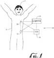
- FIG. 1illustrates a generalized representation of a system 10 in accordance with the described arrangements.
- the system 10includes a delivery device 12.
- the system 10may further include a sensing device 14, a command control device (CCD) 16, and a computer 18.
- the delivery device 12 and the sensing device 14may be secured at desired locations on the body 5 of a patient or user 7.
- the locations at which the delivery device 12 and the sensing device 14 are secured to the body 5 of the user 7 in FIG. 1are provided only as representative, non-limiting, examples.
- the delivery device 12is configured to deliver a fluidic medium to the body 5 of the user 7.
- the fluidic mediumincludes a liquid, a fluid, a gel, or the like.
- the fluidic mediumincludes a medicine or a drug for treating a disease or a medical condition.
- the fluidic mediummay include insulin for treating diabetes, or may include a drug for treating pain, cancer, a pulmonary disorder, HIV, or the like.
- the fluidic mediumincludes a nutritional supplement, a dye, a tracing medium, a saline medium, a hydration medium, or the like.
- the sensing device 14includes a sensor, a monitor, or the like, for providing sensor data or monitor data.
- the sensing device 14may be configured to sense a condition of the user 7.
- the sensing device 14may include electronics and enzymes reactive to a biological condition, such as a blood glucose level, or the like, of the user 7.
- the sensing device 14may be secured to the body 5 of the user 7 or embedded in the body 5 of the user 7 at a location that is remote from the location at which the delivery device 12 is secured to the body 5 of the user 7.
- the sensing device 14may be incorporated within the delivery device 12.
- Each of the delivery device 12, the sensing device 14, the CCD 16, and the computer 18may include transmitter, receiver, or transceiver electronics that allow for communication with other components of the system 10.
- the sensing device 14may be configured to transmit sensor data or monitor data to the delivery device 12.
- the sensing device 14may also be configured to communicate with the CCD 16.
- the delivery device 12may include electronics and software that are configured to analyze sensor data and to deliver the fluidic medium to the body 5 of the user 7 based on the sensor data and/or preprogrammed delivery routines.
- the CCD 16 and the computer 18may include electronics and other components configured to perform processing, delivery routine storage, and to control the delivery device 12. By including control functions in the CCD 16 and/or the computer 18, the delivery device 12 may be made with more simplified electronics. However, in some arrangements, the delivery device 12 may include all control functions, and may operate without the CCD 16 and the computer 18. In various embodiments, the CCD 16 may be a portable electronic device. Also, in various arrangements, the delivery device 12 and/or the sensing device 14 may be configured to transmit data to the CCD 16 and/or the computer 18 for display or processing of the data by the CCD 16 and/or the computer 18.
- FIG. 2illustrates an example of the system 10.
- the system 10in accordance with the arrangement illustrated in FIG. 2 includes the delivery device 12 and the sensing device 14.
- the delivery device 12includes a disposable housing 20, a durable housing 30, and a reservoir 40.
- the delivery device 12may further include an infusion path 50.
- a disposable portion of the delivery device 12may include the disposable housing 20 and the reservoir 40.
- the disposable portion of the delivery device 12may be recommended for disposal after a specified number of uses.
- a durable portion of the delivery device 12may include the durable housing 30, electronics (not shown in FIG. 2 ), a drive device having a motor and drive linkage (not shown in FIG. 2 ), and the like. Elements of the durable housing portion of the delivery device 12 are typically not contaminated from contact with the user or the fluidic medium during normal operation of the delivery device 12 and, thus, may be retained for re-use with replaced disposable portions of the delivery device 12.
- the disposable housing 20supports the reservoir 40 and has a bottom surface (facing downward and into the page in FIG. 2 ) that is configured to secure to the body of a user.
- An adhesivemay be employed at an interface between the bottom surface of the disposable housing 20 and the skin of a user, so as to adhere the disposable housing 20 to the skin of the user.
- the adhesivemay be provided on the bottom surface of the disposable housing 20, with a peelable cover layer covering the adhesive material. In this manner, the cover layer may be peeled off to expose the adhesive material, and the adhesive side of the disposable housing 20 may be placed against the skin of the user.
- the reservoir 40is configured for containing or holding a fluidic medium, such as, but not limited to insulin.
- the reservoir 40includes a hollow interior volume for receiving the fluidic medium, such as, but not limited to, a cylinder-shaped volume, a tubular-shaped volume, or the like.
- the reservoir 40may be provided as a cartridge or canister for containing a fluidic medium.
- the reservoir 40is able to be refilled with a fluidic medium.
- the reservoir 40may be supported by the disposable housing 20 in any suitable manner.
- the disposable housing 20may be provided with projections or struts (not shown), or a trough feature (not shown), for holding the reservoir 40.
- the reservoir 40may be supported by the disposable housing 20 in a manner that allows the reservoir 40 to be removed from the disposable housing 20 and replaced with another reservoir.
- the reservoir 40may be secured to the disposable housing 20 by a suitable adhesive, a strap, or other coupling structure.
- the reservoir 40includes a port 41 for allowing a fluidic medium to flow into and/or flow out of the interior volume of the reservoir 40.
- the infusion path 50includes a connector 56, a tube 54, and a needle apparatus 52.
- the connector 56 of the infusion path 50may be connectable to the port 41 of the reservoir 40.
- the disposable housing 20is configured with an opening near the port 41 of the reservoir 40 for allowing the connector 56 of the infusion path 50 to be selectively connected to and disconnected from the port 41 of the reservoir 40.
- the port 41 of the reservoir 40is covered with or supports a septum (not shown in FIG. 2 ), such as a self-sealing septum, or the like.
- the septummay be configured to prevent a fluidic medium from flowing out of the reservoir 40 through the port 41 when the septum is not pierced.
- the connector 56 of , the infusion path 50includes a needle for piercing the septum covering the port 41 of the reservoir 40 so as to allow the fluidic medium to flow out of the interior volume of the reservoir 40. Examples of needle/septum connectors can be found in U.S. Patent Application US 2003/125672 published 3 July 2003 , entitled "Reservoir Connector".
- the needle apparatus 52 of the infusion path 50includes a needle that is able to puncture the skin of a user.
- the tube 54connects the connector 56 with the needle apparatus 52 and is hollow, such that the infusion path 50 is able to provide a path to allow for the delivery of a fluidic medium from the reservoir 40 to the body of a user.
- the durable housing 30 of the delivery device 12includes a housing shell configured to mate with and secure to the disposable housing 20.
- the durable housing 30 and the disposable housing 20may be provided with correspondingly shaped grooves, notches, tabs, or other suitable features, that allow the two parts to easily connect together, by manually pressing the two housings together, by twist or threaded connection, or other suitable manner of connecting the parts that is well known in the mechanical arts.
- the durable housing 30 and the disposable housing 20may be connected to each other using a twist action.
- the durable housing 30 and the disposable housing 20may be configured to be separable from each other when a sufficient force is applied to disconnect the two housings from each other.
- the disposable housing 20 and the durable housing 30may be snapped together by friction fitting.
- a suitable sealsuch as an o-ring seal, may be placed along a peripheral edge of the durable housing 30 and/or the disposable housing 20, so as to provide a seal against water entering between the durable housing 30 and the disposable housing 20.
- the durable housing 30 of the delivery device 12may support a drive device (not shown in FIG. 2 ), including a motor and a drive device linkage portion, for applying a force to the fluidic medium within the reservoir 40 to force the fluidic medium out of the reservoir 40 and into an infusion path, such as the infusion path 50, for delivery to a user.
- a drive device(not shown in FIG. 2 ), including a motor and a drive device linkage portion, for applying a force to the fluidic medium within the reservoir 40 to force the fluidic medium out of the reservoir 40 and into an infusion path, such as the infusion path 50, for delivery to a user.
- an electrically driven motormay be mounted within the durable housing 30 with appropriate linkage for operatively coupling the motor to a plunger arm (not shown in FIG. 2 ) connected to a plunger head (not shown in FIG. 2 ) that is within the reservoir 40 and to drive the plunger head in a direction to force the fluidic medium out of the port 41 of the reservoir 40 and to the user.
- the motormay be controllable to reverse direction so as to move the plunger arm and the plunger head to cause fluid to be drawn into the reservoir 40 from a patient.
- the motormay be arranged within the durable housing 30 and the reservoir 40 may be correspondingly arranged on the disposable housing 20, such that the operable engagement of the motor with the plunger head, through the appropriate linkage, occurs automatically upon the user connecting the durable housing 30 with the disposable housing 20 of the delivery device 12. Further examples of linkage and control structures may be found in U.S. Patent Application US 2001/ 41869 published 15 November 2001 , entitled "Control Tabs for Infusion Devices and Methods of Using the Same".
- the durable housing 30 and the disposable housing 20may be made of suitably rigid materials that maintain their shape, yet provide sufficient flexibility and resilience to effectively connect together and disconnect, as described above.
- the material of the disposable housing 20may be selected for suitable compatibility with skin.
- the disposable housing 20 and the durable housing 30 of the delivery device 12may be made of any suitable plastic, metal, composite material, or the like.
- the disposable housing 20may be made of the same type of material or a different material relative to the durable housing 30.
- the disposable housing 20 and the durable housing 30may be manufactured by injection molding or other molding processes, machining processes, or combinations thereof.
- the disposable housing 20may be made of a relatively flexible material, such as a flexible silicone, plastic, rubber, synthetic rubber, or the like.
- a relatively flexible materialsuch as a flexible silicone, plastic, rubber, synthetic rubber, or the like.
- the delivery device 12is connected to the sensing device 14 through a connection element 16 of the sensing device 14.
- the sensing device 14may include a sensor 15 that includes any suitable biological or environmental sensing device, depending upon a nature of a treatment to be administered by the delivery device 12.
- the sensor 15may include a blood glucose sensor, or the like.
- the sensor 15may be an external sensor that secures to the skin of a user or, in other arrangements, may be an implantable sensor that is located in an implant site within the body of the user. In further alternatives, the sensor may be included with as a part or along side the infusion cannula and/or needle, such as for example as shown in U.S. Patent Application US 2006/253085 published 9 November 2006 , entitled "Dual Insertion Set".
- the sensor 15is an external sensor having a disposable needle pad that includes a needle for piercing the skin of the user and enzymes and/or electronics reactive to a biological condition, such as blood glucose level or the like, of the user.
- the delivery device 12may be provided with sensor data from the sensor 15 secured to the user at a site remote from the location at which the delivery device 12 is secured to the user.
- FIG. 2While the arrangement shown in FIG. 2 includes a sensor 15 connected by the connection element 16 for providing sensor data to sensor electronics (not shown in FIG. 2 ) located within the durable housing 30 of the delivery device 12, other arrangements may employ a sensor 15 located within the delivery device 12. Yet other arrangements may employ a sensor 15 having a transmitter for communicating sensor data by a wireless communication link with receiver electronics (not shown in FIG. 2 ) located within the durable housing 30 of the delivery device 12.
- a wireless connection between the sensor 15 and the receiver electronics within the durable housing 30 of the delivery device 12may include a radio frequency (RF) connection, an optical connection, or another suitable wireless communication link. Further arrangements need not employ the sensing device 14 and, instead, may provide fluidic medium delivery functions without the use of sensor data.
- RFradio frequency
- the disposable elementsmay be arranged on the disposable housing 20, while durable elements may be arranged within a separable durable housing 30.
- the disposable housing 20may be separated from the durable housing 30, so that the disposable housing 20 may be disposed of in a proper manner.
- the durable housing 30may then be mated with a new (unused) disposable housing 20 for further delivery operation with a user.
- FIG. 3illustrates an example of the delivery device 12.
- the delivery device 12 of the arrangement of FIG. 3is similar to the delivery device 12 of the arrangement of FIG 2 . While the delivery device 12 in the arrangement illustrated in FIG. 2 provides for the durable housing 30 to cover the reservoir 40, the delivery device 12 in the arrangement of FIG. 3 provides for the durable housing 30 to secure to the disposable housing 20 without covering the reservoir 40.
- the delivery device 12 of the arrangement illustrated in FIG. 3includes the disposable housing 20, and the disposable housing 20 in accordance with the arrangement illustrated in FIG. 3 includes a base 21 and a reservoir retaining portion 24. In one arrangement, the base 21 and reservoir retaining portion 24 may be formed as a single, unitary structure.
- the base 21 of the disposable housing 20is configured to be secured to the body of a user.
- the reservoir retaining portion 24 of the disposable housing 20is configured to house the reservoir 40.
- the reservoir retaining portion 24 of the disposable housing 20may be configured to have an opening to allow for the port 41 of the reservoir 40 to be accessed from outside of the reservoir retaining portion 24 while the reservoir 40 is housed in the reservoir retaining portion 24.
- the durable housing 30may be configured to be attachable to and detachable from the base 21 of the disposable housing 20.
- the delivery device 12 in the arrangement illustrated in FIG. 3includes a plunger arm 60 that is connected to or that is connectable to a plunger head (not shown in FIG. 3 ) within the reservoir 40.
- FIG. 4illustrates another view of the delivery device 12 of the embodiment of FIG. 3 .
- the delivery device 12 of the embodiment illustrated in FIG. 4includes the disposable housing 20, the durable housing 30, and the infusion path 50.
- the disposable housing 20 in the embodiment of FIG. 4includes the base 21, the reservoir retaining portion 24, and a peelable cover layer 25.
- the peelable cover layer 25may cover an adhesive material on the bottom surface 22 of the base 21.
- the peelable cover layer 25may be configured to be peelable by a user to expose the adhesive material on the bottom surface 22 of the base 21. In some embodiments, there may be multiple adhesive layers on the bottom surface 22 of the base 21 that are separated by peelable layers.
- the infusion path 50 illustrated in FIG. 4includes the needle 58 rather than the connector 56, the tube 54, and the needle apparatus 52 as shown in the embodiment of FIG. 2 .
- the base 21 of the disposable housing 20may be provided with an opening or pierceable wall in alignment with a tip of the needle 58, to allow the needle 58 to pass through the base 21 and into the skin of a user under the base 21, when extended. In this manner, the needle 58 may be used to pierce the skin of the user and deliver a fluidic medium to the user.
- the needle 58may be extended through a hollow cannula (not shown in FIG. 4 ), such that upon piercing the skin of the user with the needle 58, an end of the hollow cannula is guided through the skin of the user by the needle 58. Thereafter, the needle 58 may be removed, leaving the hollow cannula in place, with one end of the cannula located within the body of the user and the other end of the cannula in fluid flow connection with the fluidic medium within the reservoir 40, to convey pumped infusion media from the reservoir 40 to the body of the user.
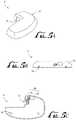
- FIG. 5Aillustrates a durable portion 8 of the delivery device 12 (refer to FIG. 3 ).
- FIG. 5Billustrates a section view of the durable portion 8.
- FIG. 5Cillustrates another section view of the durable portion 8.
- the durable portion 8includes the durable housing 30, and a drive device 80.
- the drive device 80includes a motor 84 and a drive device linkage portion 82.
- the durable housing 30may include an interior volume for housing the motor 84, the drive device linkage portion 82, other electronic circuitry, and a power source (not shown in FIGs. 5A, 5B, and 5C ). Also the durable housing 30 may be configured with an opening 32 for receiving a plunger arm 60 (refer to FIG. 3 ). Also, in various embodiments, the durable housing 30 may include one or more connection members 34, such as tabs, insertion holes, or the like, for connecting with the base 21 of the disposable housing 20 (refer to FIG. 3 ).
- FIG. 6Aillustrates a disposable portion 9 of the delivery device 12 (refer to FIG. 3 ).
- FIG. 6Billustrates a section view of the disposable portion 9.
- FIG. 6Cillustrates another section view of the disposable portion 9.
- the disposable portion 9includes the disposable housing 20, the reservoir 40, the plunger arm 60, and a plunger head 70.
- the disposable housing 20includes the base 21 and the reservoir retaining portion 24.
- the base 21includes a top surface 23 having one or more connection members 26, such as tabs, grooves, or the like, for allowing connections with the one or more connection members 34 of arrangements of the durable housing 30 (refer to FIG. 5B ).
- the reservoir 40is housed within the reservoir retaining portion 24 of the disposable housing 20, and the reservoir 40 is configured to hold a fluidic medium.
- the plunger head 70is disposed at least partially within the reservoir 40 and is moveable within the reservoir 40 to allow the fluidic medium to fill into the reservoir 40 and to force the fluidic medium out of the reservoir 40.
- the plunger arm 60is connected to or is connectable to the plunger head 70.
- a portion of the plunger arm 60extends to outside of the reservoir retaining portion 24 of the disposable housing 20.
- the plunger arm 60has a mating portion for mating with the drive device linkage portion 82 of the drive device 80 (refer to FIG. 5C ).
- the durable housing 30may be snap fitted onto the disposable housing 20, whereupon the drive device linkage portion 82 automatically engages the mating portion of the plunger arm 60.
- the motor 84may be controlled to drive the drive device linkage portion 82 and, thus, move the plunger arm 60 to cause the plunger head 70 to move within the reservoir 40.
- the plunger head 70may be moved within the reservoir 40 to force the fluidic medium from the reservoir 40 and into the infusion path, so as to deliver the fluidic medium to the body of the user.
- the reservoir 40may be refilled with a fluidic medium.
- the reservoir 40may be refilled while remaining within the reservoir retaining portion 24 (refer to FIG. 6B ) of the disposable housing 20.
- the reservoir 40may be replaced with a new reservoir (not shown), while the disposable housing 20 may be re-used with the new reservoir. In such arrangements, the new reservoir may be inserted into the disposable portion 9.
- the delivery device 12includes reservoir status circuitry (not shown), and the reservoir 40 includes reservoir circuitry (not shown).
- the reservoir circuitrystores information such as, but not limited to, at least one of (i) an identification string identifying the reservoir 40; (ii) a manufacturer of the reservoir 40; (iii) contents of the reservoir 40; and (iv) an amount of contents in the reservoir 40.
- the delivery device 12includes the reservoir status circuitry (not shown), and the reservoir status circuitry is configured to read data from the reservoir circuitry when the reservoir 40 is inserted into the disposable portion 9.
- the reservoir status circuitryis further configured to store data to the reservoir circuitry after at least some of the contents of the reservoir 40 have been transferred out of the reservoir 40, so as to update information in the reservoir circuitry related to an amount of contents still remaining in the reservoir 40.
- the reservoir status circuitryis configured to store data to the reservoir circuitry, so as to update information in the reservoir circuitry related to an amount of contents still remaining in the reservoir 40, when the reservoir 40 is inserted into the disposable portion 9.
- the delivery device 12includes the reservoir status circuitry (not shown) and the reservoir 40 includes the reservoir circuitry (not shown), and the reservoir status circuitry selectively inhibits use of the delivery device 12 or selectively provides a warning signal based on information read by the reservoir status circuitry from the reservoir circuitry.
- FIGS. 9A , 10A , 11A , 12A , and 12Cillustrate systems in accordance with various embodiments of the present invention that include reservoirs with geometries that allow for capturing air bubbles so as to reduce a number of air bubbles that are delivered with a fluidic medium.
- Such systemsallow for air bubble management since they have bubble trapping shapes and, by reducing a number of air bubbles that are delivered with a fluidic medium, such systems may be able to improve a delivery accuracy when attempting to deliver a specified volume of the fluidic medium.
- Such systemsprovide reservoir geometries that allow for capturing a greater amount of air bubbles than with standard reservoir geometries, so that the captured air bubbles remain in the reservoir and are not dispensed with the fluidic medium.
- the systems in FIGS. 9A , 10A , 11A , 12A , and 12Cmay include similar elements as elements of embodiments of the delivery device 12 (refer to FIGS. 2 and 3 ), in which case the reservoirs in those systems would correspond to the reservoir 40 (refer to FIGS. 2 , 3 , and 6C ).
- reservoirs of the systems in FIGS. 9A , 10A , 11A , 12A , and 12Cmay be made of a material, such as but not limited to a suitable metal, plastic, ceramic, glass, composite material, or the like.
- the plunger heads of the systems in those figuresmay be made of a suitably rigid material such as, but not limited to, metal, plastic, ceramic, glass, composite material, or the like.
- the plunger heads in those systemsmay be made of a compressible material such as, but not limited to, an elastically compressible plastic, rubber, silicone, or the like.
- FIG. 9Aillustrates a cross-sectional view of a system 200 in accordance with an embodiment of the present invention.
- the system 200includes a reservoir 210, a plunger head 220, and a plunger arm 230.
- the reservoir 210includes a body portion 211, a bubble trap portion 212, and a port 217.
- the reservoir 210has an outer surface 213 and an inner surface 214.
- the inner surface 214 of the reservoir 210defines a hollow interior of the reservoir 210, and the hollow interior of the reservoir 210 is able to contain a fluidic medium.
- the port 217 of the reservoir 210allows for the fluidic medium to be filled into or expelled from the hollow interior of the reservoir 210.
- the body portion 211 of the reservoir 210may have any suitable shape, such as but not limited to, a cylinder shape, a tube shape, a barrel shape, a spherical shape, a shape with a rectangular cross-section, or the like.
- the plunger head 220is located within the reservoir 210, and is moveable in an axial direction of the reservoir 210, to expand or contract a volume of the reservoir 210 in which a fluidic medium may be contained.
- the plunger head 220is connected to the plunger arm 230, such that movement of the plunger arm 230 in the axial direction of the reservoir 210 causes movement of the plunger head 220 in the axial direction of the reservoir 210.
- the plunger head 220includes a plunger body portion 221 and a plunger protruding portion 222.
- the plunger head 220further includes one or more O-rings 225 that surround a portion of the plunger body portion 221.
- the one or more O-rings 225may be made of any suitable material, such as but not limited to, rubber, plastic, composite material, or the like.
- the bubble trap portion 212 of the reservoir 210is shaped to have a volume 216 within an interior of the reservoir 210, such that air bubbles in a fluidic medium may be trapped in the volume 216 when the fluidic medium is expelled from the reservoir 210 through the port 217.
- an interior surface of the bubble trap portion 212is curved or angled near the port 217, so as to define the volume 216.
- the bubble trap portion 212extends from the body portion 211 of the reservoir 210 past a point 218 of the reservoir 210 where a fluidic medium from an interior volume of the body portion 211 is able to move into an area or channel 272 of the reservoir 210 that leads to the port 217.
- the reservoir 210is shaped such that as the plunger head 220 is advanced within the reservoir 210, a fluidic medium is able to pass through the port 217 while air bubbles in the reservoir 210 collect in the volume 216 defined by a curved or angled surface of the bubble trap portion 212 of the reservoir 210.
- a geometry of the reservoir 210allows for decreasing an amount of air bubbles that are delivered with a fluidic medium as compared with traditional reservoir geometries.
- the bubble trap portion 212 of the reservoir 210is curved outward from an interior volume defined by the body portion 211, and a fluidic medium is able to pass directly from the interior volume defined by the body portion 211 to the port 217.
- a surface 215 of the bubble trap portion 212 of the reservoir 210includes a surface finish or material such that air bubbles substantially do no stick to the surface 215 and are shunted away from the port 217 toward the volume 216.
- a surface finish or materialincludes a hydrophobic material, a hydrophilic material, or other suitable material.
- the plunger body portion 221is shaped such that a contour of the plunger body portion 221 substantially matches or is substantially the same as an inner contour of the body portion 211 of the reservoir 210.
- the plunger body portion 221has a diameter that is slightly smaller than a diameter of the inner surface of the body portion 211 of the reservoir 210, such that the plunger head 220 is able to slide within the reservoir 210.
- an O-ring 225 on the plunger body portion 221is in contact with the inner surface of the body portion 211 of the reservoir 210 when the plunger head 220 is within the reservoir 210.
- the plunger protruding portion 222is shaped such that a contour of the plunger protruding portion 222 substantially matches or is substantially the same as an inner contour of the bubble trap portion 212 of the reservoir 210. In some embodiments, the plunger protruding portion 222 is curved and protrudes from the plunger body portion 221. In various embodiments, the plunger protruding portion 222 has a size that is slightly smaller than a region defined by the inner surface of the bubble trap portion 212 of the reservoir 210, such that the plunger protruding portion 222 is able to slide within the volume 216 of the reservoir 210, and such that a space for a dead volume of air is left when the plunger head 220 is fully advanced within the reservoir 210. Thus, in various embodiments, the geometry of the reservoir 210 and the plunger head 220 allow for capturing air bubbles in a volume 216 of the bubble trap portion 212 when a fluidic medium is being expelled from the port 217 of the reservoir 210.
- the plunger protruding portion 222has a size such that when the plunger head 220 is fully advanced within the reservoir 210, the plunger protruding portion 222 fills at least 80% of the volume 216 of the bubble trap portion 212. Also, in various embodiments, the plunger protruding portion 222 fills less than 98% of the volume 216 of the bubble trap portion 212 when the plunger head 220 is fully advanced within the reservoir 210, so that one or more air pockets for holding air exist between the plunger protruding portion 222 and an inner surface of the bubble trap portion 212 when the plunger head 220 is fully advanced within the reservoir 210. In some embodiments, the plunger protruding portion 222 extends at least partially into the volume 216 of the bubble trap portion 212 when the plunger head 220 is sufficiently advanced within the reservoir 210.
- FIG. 9Billustrates a cross-sectional view of the reservoir 210 in accordance with an embodiment of the present invention.
- FIG. 9Bis shaded to highlight various features of the reservoir 210.
- the reservoir 210includes the body portion 211, the bubble trap portion 212, and the port 217.
- the body portion 211has an interior volume 270 for containing a fluidic medium.
- the port 217is in fluid flow communication with the interior volume 270 of the body portion 211.
- the bubble trap portion 212has the volume 216 in fluid flow communication with the interior volume 270 of the body portion 211 for trapping air bubbles that are in the fluidic medium as the fluidic medium is being expelled from the interior volume 270.
- the port 217is located to a particular side of the interior volume 270
- the bubble trap portion 212is located to the particular side of the interior volume 270.
- the bubble trap portion 212has a first portion 281 that extends from the body portion 211 away from the interior volume 270, and a second portion 282 that returns back toward the interior volume 270.
- the body portion 211 and the bubble trap portion 212are formed together as a single seamless unit.
- the first portion 281 of the bubble trap portion 212extends from the body portion 211 away from the interior volume 270 and the second portion 282 of the bubble trap portion 212 extends from the first portion 281 toward the interior volume 270.
- the bubble trap portion 212includes a curved surface 283 having a first end region 284, a second end region 285, and a middle region 286 between the first end region 284 and the second end region 285.
- the first end region 284 and the second end region 285are closer to the interior volume 270 of the body portion 211 than the middle region 286 is to the interior volume 270.
- the first end region 284is in contact with the body portion 211, and the second end region 285 is located adjacent to the interior volume 270 of the body portion 211.
- the curved surface 283 of the bubble trap portion 212is in contact with the fluidic medium when the fluidic medium is in the volume 216 of the bubble trap portion 212. In further embodiments, the curved surface 283 is approximately U-shaped. FIG. 9B illustrates a cross-sectional view, but in three-dimensions the bubble trap portion 212 may be shaped, for example, approximately as a semi-toroid.
- the reservoir 210is shaped such that in order for a fluidic medium to flow from the volume 216 of the bubble trap portion 212 to the port 217, the fluidic medium must flow through the interior volume 270 of the body portion 211.
- the reservoir 210includes the channel 272 that leads from the interior volume 270 of the body portion 211 to the port 217, and the bubble trap portion 212 encircles at least a portion of the channel 272.
- FIG. 10Aillustrates a cross-sectional view of a system 300 in accordance with an embodiment of the present invention.
- the system 300includes a reservoir 310, a plunger head 320, and a plunger arm 330.
- the reservoir 310includes a body portion 311, a bubble trap portion 312, and a port 317.
- the reservoir 310has an outer surface 313 and an inner surface 314.
- the inner surface 314 of the reservoir 310defines a hollow interior of the reservoir 310, and the hollow interior of the reservoir 310 is able to contain a fluidic medium.
- the port 317 of the reservoir 310allows for the fluidic medium to be filled into or expelled from the hollow interior of the reservoir 310.
- the body portion 311 of the reservoir 310may have any suitable shape, such as but not limited to, a cylinder shape, a tube shape, a barrel shape, a spherical shape, a shape with a rectangular cross-section, or the like.
- the plunger head 320is located within the reservoir 310, and is moveable in an axial direction of the reservoir 310, to expand or contract a volume of the reservoir 310 in which a fluidic medium may be contained.
- the plunger head 320is connected to the plunger arm 330, such that movement of the plunger arm 330 in the axial direction of the reservoir 310 causes movement of the plunger head 320 in the axial direction of the reservoir 310.
- the plunger head 320includes a plunger body portion 321 and a plunger protruding portion 322.
- the plunger head 320further includes one or more O-rings 325 that surround a portion of the plunger body portion 321.
- the bubble trap portion 312 of the reservoir 310is shaped so as to form a volume 316 within an interior of the reservoir 310, such that air bubbles in a fluidic medium may be trapped in the volume 316 of the bubble trap portion 312 when the fluidic medium is expelled from the reservoir 310 through the port 317.
- an interior surface of the bubble trap portion 312is angled at a substantially straight angle near the port 317, so as to define the volume 316.
- the bubble trap portion 312extends from the body portion 311 of the reservoir 310 past a point 318 of the reservoir 310 where a fluidic medium from an interior volume of the body portion 311 is able to move into an area or channel 372 of the reservoir 310 that leads to the port 317.
- the reservoir 310is shaped such that as the plunger head 320 is advanced within the reservoir 310, a fluidic medium is able to pass through the port 317 while air bubbles in the reservoir 310 collect in the volume 316 defined by a substantially straight angled surface of the bubble trap portion 312 of the reservoir 310.
- a geometry of the reservoir 310may allow for decreasing an amount of air bubbles that are delivered with a fluidic medium as compared with traditional reservoir geometries.
- the bubble trap portion 312 of the reservoir 310is angled outward from an interior region of the reservoir 310 defined by the body portion 311, and a fluidic medium is able to pass directly from the interior region of the reservoir 310 defined by the body portion 311 to the port 317.
- a surface 315 of the bubble trap portion 312 of the reservoir 310includes a surface finish or material such that air bubbles substantially do no stick to the surface 315 and are shunted away from the port 317 toward the volume 316.
- the plunger body portion 321is shaped such that a contour of the plunger body portion 321 substantially matches or is substantially the same as a contour of an inner surface of the body portion 311 of the reservoir 310.
- the plunger body portion 321has a diameter that is slightly smaller than a diameter of the inner surface of the body portion 311 of the reservoir 310, such that the plunger head 320 is able to slide within the reservoir 310.
- the one or more O-rings 325 on the plunger body portion 321are in contact with the inner surface of the body portion 311 of the reservoir 310 when the plunger head 320 is within the reservoir 310.
- the plunger protruding portion 322is shaped such that a contour of the plunger protruding portion 322 substantially matches or is substantially the same as an inner contour of the bubble trap portion 312 of the reservoir 310. In some embodiments, the plunger protruding portion 322 is angled from the plunger body portion 321 at a substantially straight angle and protrudes from the plunger body portion 321.
- the plunger protruding portion 322has a size that is slightly smaller than a region defined by the inner surface of the bubble trap portion 312 of the reservoir 310, such that the plunger protruding portion 322 is able to slide within the volume 316 of the bubble trap portion 312, and such that a space for a dead volume of air is left when the plunger head 320 is fully advanced within the reservoir 310.
- the geometry of the reservoir 310 and the plunger head 320allow for capturing air bubbles in a volume 316 of the bubble trap portion 312 when a fluidic medium is being expelled from the port 317 of the reservoir 310.
- the plunger protruding portion 322has a size such that when the plunger head 320 is fully advanced within the reservoir 310, the plunger protruding portion 322 fills at least 80% of the volume 316 of the bubble trap portion 312. Also, in various embodiments, the plunger protruding portion 322 fills less than 98% of the volume 316 of the bubble trap portion 312 when the plunger head 320 is fully advanced within the reservoir 310, so that one or more air pockets for holding air exist between the plunger protruding portion 322 and an inner surface of the bubble trap portion 312 when the plunger head 320 is fully advanced within the reservoir 310. In some embodiments, the plunger protruding portion 322 extends at least partially into the volume 316 of the bubble trap portion 312 when the plunger head 320 is sufficiently advanced within the reservoir 310.
- FIG. 10Billustrates a cross-sectional view of the reservoir 310 in accordance with an embodiment of the present invention.
- FIG. 10Bis shaded to highlight various features of the reservoir 310.
- the reservoir 310includes the body portion 311, the bubble trap portion 312, and the port 317.
- the body portion 311has an interior volume 370 for containing a fluidic medium.
- the port 317is in fluid flow communication with the interior volume 370 of the body portion 311.
- the bubble trap portion 312has the volume 316 in fluid flow communication with the interior volume 370 of the body portion 311 for trapping air bubbles that are in the fluidic medium as the fluidic medium is being expelled from the interior volume 370.
- the port 317is located to a particular side of the interior volume 370
- the bubble trap portion 312is located to the particular side of the interior volume 370.
- the bubble trap portion 312has a first portion 381 that extends from the body portion 311 away from the interior volume 370, and a second portion 382 that returns back toward the interior volume 370.
- the body portion 311 and the bubble trap portion 312are formed together as a single seamless unit.
- the first portion 381 of the bubble trap portion 312extends from the body portion 311 away from the interior volume 370 and the second portion 382 of the bubble trap portion 312 extends from the first portion 381 toward the interior volume 370.
- the reservoir 310is shaped such that in order for a fluidic medium to flow from the volume 316 of the bubble trap portion 312 to the port 317, the fluidic medium must flow through the interior volume 370 of the body portion 311.
- the reservoir 310includes the channel 372 that leads from the interior volume 370 of the body portion 311 to the port 317, and the bubble trap portion 312 encircles at least a portion of the channel 372.
- the bubble trap portion 312includes a first surface 383 that defines an edge of the volume 316 of the bubble trap portion 312, and a second surface 384 that defines another edge of the volume 316 of the bubble trap portion 312, where the second surface 384 is positioned at an angle with respect to the first surface 383. In some embodiments, the angle between the first surface 383 and the second surface 384 is less than 90 degrees. Also, in some embodiments, the first surface 383 is planar with respect to an inner surface of the body portion 311 of the reservoir 310. In various embodiments, the port 317 is located to a particular side of the interior volume 370 and the first portion 381 of the bubble trap portion 312 extends from the body portion 311 to the particular side.
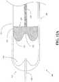
- FIG. 11Aillustrates a cross-sectional view of a system 400 in accordance with an embodiment of the present invention.
- the system 400includes a reservoir 410, a plunger head 420, and a plunger arm 430.
- the reservoir 410includes a body portion 411, a bubble trap portion 412, and a port 417.
- the reservoir 410has an outer surface 413 and an inner surface 414.
- the inner surface 414 of the reservoir 410defines a hollow interior of the reservoir 410, and the hollow interior of the reservoir 410 is able to contain a fluidic medium.
- the port 417 of the reservoir 410allows for the fluidic medium to be filled into or expelled from the hollow interior of the reservoir 410.
- the body portion 411 of the reservoir 410may have any suitable shape, such as but not limited to, a cylinder shape, a tube shape, a barrel shape, a spherical shape, a shape with a rectangular cross-section, or the like.
- the plunger head 420is located within the reservoir 410, and is moveable in an axial direction of the reservoir 410, to expand or contract a volume of the reservoir 410 in which a fluidic medium may be contained.
- the plunger head 420is connected to the plunger arm 430, such that movement of the plunger arm 430 in the axial direction of the reservoir 410 causes movement of the plunger head 420 in the axial direction of the reservoir 410.
- the plunger head 420includes a plunger body portion 421 and a plunger protruding portion 422.
- the plunger head 420further includes one or more O-rings 425 that surround a portion of the plunger body portion 421.
- the bubble trap portion 412 of the reservoir 410is shaped so as to form a volume 416 within an interior of the reservoir 410, such that air bubbles in a fluidic medium may be trapped in the volume 416 of the bubble trap portion 412 when the fluidic medium is expelled from the reservoir 410 through the port 417.
- the reservoir 410is shaped such that as the plunger head 420 is advanced within the reservoir 410, a fluidic medium is able to pass through the port 417 while air bubbles in the reservoir 410 collect in the volume 416 of the reservoir 410.
- Such a geometry of the reservoir 410may allow for decreasing an amount of air bubbles that are delivered with a fluidic medium as compared with traditional reservoir geometries.
- the plunger body portion 421is shaped such that a contour of an outer surface of the plunger body portion 421 substantially matches or is substantially the same as a contour of an inner surface of the body portion 411 of the reservoir 410.
- the plunger body portion 421has a diameter that is slightly smaller than a diameter of the inner surface of the body portion 411 of the reservoir 410, such that the plunger head 420 is able to slide within the reservoir 410.
- the one or more O-rings 425 on the plunger body portion 421are in contact with the inner surface of the body portion 411 of the reservoir 410 when the plunger head 420 is within the reservoir 410.
- the plunger protruding portion 422is shaped such that a contour of an outer surface of the plunger protruding portion 422 substantially matches or is substantially the same as a contour of an inner surface of the bubble trap portion 412 of the reservoir 410.
- FIG. 11Billustrates a cross-sectional view of the reservoir 410 in accordance with an embodiment of the present invention.
- FIG. 11Bis shaded to highlight various features of the reservoir 410.
- the reservoir 410includes the body portion 411, the bubble trap portion 412, and the port 417.
- the body portion 411has an interior volume 470 for containing a fluidic medium.
- the port 417is in fluid flow communication with the interior volume 470 of the body portion 411.
- the bubble trap portion 412has the volume 416 in fluid flow communication with the interior volume 470 of the body portion 411 for trapping air bubbles that are in the fluidic medium as the fluidic medium is being expelled from the interior volume 470.
- the port 417is located to a particular side of the interior volume 470
- the bubble trap portion 412is located to the particular side of the interior volume 470.
- the bubble trap portion 412has a first portion 481 that extends from the body portion 411 away from the interior volume 470, and a second portion 482 that returns back toward the interior volume 470.
- the body portion 411 and the bubble trap portion 412are formed together as a single seamless unit.
- the first portion 481 of the bubble trap portion 412extends from the body portion 411 away from the interior volume 470 and the second portion 482 of the bubble trap portion 412 extends from the first portion 481 toward the interior volume 470.
- the bubble trap portion 412includes a curved surface 483. In some embodiments, the curved surface 483 of the bubble trap portion 412 is in contact with the fluidic medium when the fluidic medium is in the volume 416 of the bubble trap portion 412. In various embodiments, the reservoir 410 is shaped such that in order for a fluidic medium to flow from the volume 416 of the bubble trap portion 412 to the port 417, the fluidic medium must flow through the interior volume 470 of the body portion 411. In some embodiments, the reservoir 410 includes a channel 472 that leads from the interior volume 470 of the body portion 411 to the port 417, and the bubble trap portion 412 encircles at least a portion of the channel 472.
- the plunger protruding portion 422is shaped such that a contour of the plunger protruding portion 422 substantially matches or is substantially the same as an inner contour of the bubble trap portion 412 of the reservoir 410.
- the plunger protruding portion 422is at least partially curved and protrudes from the plunger body portion 421.
- the plunger protruding portingincludes a surface that is substantially parallel to an inner surface of the body portion 411 of the reservoir 410.
- the plunger protruding portion 422has a size that is slightly smaller than a region defined by the inner surface of the bubble trap portion 412 of the reservoir 410, such that the plunger protruding portion 422 is able to slide within the volume 416 of the reservoir 410, and such that a space for a dead volume of air is left when the plunger head 420 is fully advanced within the reservoir 410.
- the geometry of the reservoir 410 and the plunger head 420allow for capturing air bubbles in a volume 416 of the bubble trap portion 412 when a fluidic medium is being expelled from the port 417 of the reservoir 410.
- the plunger protruding portion 422has a size such that when the plunger head 420 is fully advanced within the reservoir 410, the plunger protruding portion 422 fills at least 80% of the volume 416 of the bubble trap portion 412. Also, in various embodiments, the plunger protruding portion 422 fills less than 98% of the volume 416 of the bubble trap portion 412 when the plunger head 420 is fully advanced within the reservoir 410, so that one or more air pockets for holding air exist between the plunger protruding portion 422 and an inner surface of the bubble trap portion 412 when the plunger head 420 is fully advanced within the reservoir 410. In some embodiments, the plunger protruding portion 422 extends at least partially into the volume 416 of the bubble trap portion 412 when the plunger head 420 is sufficiently advanced within the reservoir 410.
- FIG. 12Aillustrates a cross-sectional view of a system 500 in accordance with an embodiment of the present invention.
- the system 500includes a reservoir 510, a plunger head 520, and a plunger arm 530.
- the system 500further includes a needle 550.
- the reservoir 510is similar to the reservoir 210 of the system 200 (refer to FIG. 9A ), and includes a body portion 511 and a bubble trap portion 512.
- the bubble trap portion 512defines a volume 516 for trapping air bubbles.
- the reservoir 510has an air trap geometry that allows for capturing air bubbles.
- the plunger head 520is similar to the plunger head 220 of the system 200 (refer to FIG. 9A ).
- the plunger head 520includes a plunger body portion 521 and a plunger protruding portion 522.
- the plunger head 520further includes a depression or relief 523 for allowing at least a portion of the needle 550 to be inserted into an interior of the reservoir 510 when the plunger head 520 is fully advanced within the reservoir 510.
- the plunger head 520has the relief 523 for receiving at least a portion of the needle 550 when the plunger head 520 is sufficiently advanced within the reservoir 510 and the portion of the needle 550 is inserted into the reservoir 510.
- the reservoir 510is shaped to trap air bubbles.
- the reservoir 510 and the plunger head 520are shaped so as to minimize a delivery of air bubbles when a fluidic medium is expelled from the reservoir 510.
- FIG. 12Billustrates a cross-sectional view of the reservoir 510 in accordance with an embodiment of the present invention.
- FIG. 12Bis shaded to highlight various features of the reservoir 510.
- the reservoir 510includes the body portion 511, the bubble trap portion 512, and a port 517.
- the body portion 511has an interior volume 570 for containing a fluidic medium.
- the port 517is in fluid flow communication with the interior volume 570 of the body portion 511.
- the bubble trap portion 512has the volume 516 in fluid flow communication with the interior volume 570 of the body portion 511 for trapping air bubbles that are in the fluidic medium as the fluidic medium is being expelled from the interior volume 570.
- the port 517is located to a particular side of the interior volume 570
- the bubble trap portion 512is located to the particular side of the interior volume 570.
- the bubble trap portion 512has a first portion 581 that extends from the body portion 511 away from the interior volume 570, and a second portion 582 that returns back toward the interior volume 570.
- the body portion 511 and the bubble trap portion 512are formed together as a single seamless unit.
- the first portion 581 of the bubble trap portion 512extends from the body portion 511 away from the interior volume 570 and the second portion 582 of the bubble trap portion 512 extends from the first portion 581 toward the interior volume 570.
- the bubble trap portion 512includes a curved surface 583 having a first end region 584, a second end region 585, and a middle region 586 between the first end region 584 and the second end region 585.
- the first end region 584 and the second end region 585are closer to the interior volume 570 of the body portion 511 than the middle region 586 is to the interior volume 570.
- the first end region 584is in contact with the body portion 511, and the second end region 585 is located adjacent to the interior volume 570 of the body portion 511.
- the curved surface 583 of the bubble trap portion 512is in contact with the fluidic medium when the fluidic medium is in the volume 516 of the bubble trap portion 512. In further embodiments, the curved surface 583 is approximately U-shaped. FIG. 9B illustrates a cross-sectional view, but in three-dimensions the bubble trap portion 512 may be shaped, for example, approximately as a semi-toroid.
- the reservoir 510is shaped such that in order for a fluidic medium to flow from the volume 516 of the bubble trap portion 512 to the port 517, the fluidic medium must flow through the interior volume 570 of the body portion 511.
- the reservoir 510includes a channel 572 that leads from the interior volume 570 of the body portion 511 to the port 517, and the bubble trap portion 512 encircles at least a portion of the channel 572.
- FIG. 12Cillustrates a cross-sectional view of the system 500 of FIG. 12A in accordance with another embodiment of the present invention.
- the system 500further includes a plug 560.
- the plug 560is located between an interior surface 515 of the bubble trap portion 512 of the reservoir 510 and a location of the reservoir where a fluidic medium is able to be expelled from the reservoir.
- the plug 560may comprise, for example, a hydrophilic material or a hydrophobic material, that will substantially keep air bubbles from being dispensed through a port 517 of the reservoir 510.
- the plug 560shunts air bubbles in a fluidic medium away from the port 517 of the reservoir 510 and toward the volume 516 of the bubble trap portion 512 when the fluidic medium is being expelled from an interior volume of the body portion 511 of the reservoir 510.
Landscapes
- Health & Medical Sciences (AREA)
- Vascular Medicine (AREA)
- Engineering & Computer Science (AREA)
- Anesthesiology (AREA)
- Biomedical Technology (AREA)
- Heart & Thoracic Surgery (AREA)
- Hematology (AREA)
- Life Sciences & Earth Sciences (AREA)
- Animal Behavior & Ethology (AREA)
- General Health & Medical Sciences (AREA)
- Public Health (AREA)
- Veterinary Medicine (AREA)
- Dermatology (AREA)
- Emergency Medicine (AREA)
- Infusion, Injection, And Reservoir Apparatuses (AREA)
Description
- Embodiments of the present invention relate to reservoir filling, bubble management, and infusion medium delivery systems.
- According to modern medical techniques, certain chronic diseases may be treated by delivering a medication or other substance to the body of a patient. For example, diabetes is a chronic disease that is commonly treated by delivering defined amounts of insulin to a patient at appropriate times. Traditionally, manually operated syringes and insulin pens have been employed for delivering insulin to a patient. More recently, modern systems have been designed to include programmable pumps for delivering controlled amounts of medication to a patient.
- Pump type delivery devices have been configured in external devices, which connect to a patient, and have also been configured in implantable devices, which are implanted inside of the body of a patient. External pump type delivery devices include devices designed for use in a stationary location, such as a hospital, a clinic, or the like, and further include devices configured for ambulatory or portable use, such as devices that are designed to be carried by a patient, or the like. External pump type delivery devices may be connected in fluid flow communication to a patient or user, for example, through a suitable hollow tubing. The hollow tubing may be connected to a hollow needle that is designed to pierce the skin of the patient and to deliver a fluidic medium there-through. Alternatively, the hollow tubing may be connected directly to the patient as through a cannula, or the like.
- Examples of some external pump type delivery devices are described in the following references: (i) Published
PCT Application WO 01/70307 PCT/US01/09139 ), entitled "Exchangeable Electronic Cards for Infusion Devices"; (ii) Published PCT ApplicationWO 04/030716 PCT/US2003/028769 ), entitled "Components and Methods for Patient Infusion Device"; (iii) Published PCT ApplicationWO 04/030717 PCT/US2003/029019 ), entitled "Dispenser Components and Methods for Infusion Device"; (iv)U.S. Patent Application Pub. No. 2005/0065760 , entitled "Method for Advising Patients Concerning Doses Of Insulin"; and (v)U.S. Patent No. 6,589,229 , entitled "Wearable Self-Contained Drug Infusion Device". - As compared to syringes and insulin pens, pump type delivery devices can be significantly more convenient to a patient, in that doses of insulin may be calculated and delivered automatically to a patient at any time during the day or night. Furthermore, when used in conjunction with glucose sensors or monitors, insulin pumps may be automatically controlled to provide appropriate doses of a fluidic medium at appropriate times of need, based on sensed or monitored levels of blood glucose. As a result, pump type delivery devices have become an important aspect of modern medical treatments of various types of medical conditions, such as diabetes, and the like. As pump technologies improve and doctors and patients become more familiar with such devices, external medical infusion pump treatments are expected to increase in popularity and are expected to increase substantially in number over the next decade.
US2002/ 0165496 published 7 November 2002 discloses a syringe having an air release assembly slidingly clamped to the syringe barrel, the air release assembly having a slider valve.- The invention is as set out in claim 1. Optional features are as set out in the dependent claims.
- Described arrangements relate to reservoir filling, bubble management, and infusion medium delivery systems. Various embodiments of the present invention are directed to limiting a presence of air bubbles in a fluidic medium expelled from a reservoir. In various embodiments, a reservoir is shaped so as to limit a presence of air bubbles in a fluidic medium expelled from the reservoir. Also, in various embodiments, a plunger head within a reservoir is shaped so as to limit a presence of air bubbles in a fluidic medium expelled from the reservoir. In some arrangements, a reservoir is vibrated so as to shake air bubbles free in a fluidic medium being filled into the reservoir.
- A system in accordance with another embodiment of the present invention includes a reservoir. The reservoir includes a body portion, a port, and a bubble trap portion. The body portion has an interior volume for containing a fluidic medium. The port is in fluid flow communication with the interior volume. The bubble trap portion has a volume within the interior of the reservoir in fluid flow communication with the interior volume for trapping air bubbles that are in the fluidic medium as the fluidic medium is being expelled from the interior volume.
- In various embodiments, the port is located to a particular side of the interior volume, and the bubble trap portion is located to the particular side of the interior volume. In some embodiments, the bubble trap portion has a first portion that extends from the body portion away from the interior volume, and a second portion that returns back toward the interior volume. In various embodiments, the body portion and the bubble trap portion are a single seamless unit.
- In some embodiments, the bubble trap portion has a first portion that extends from the body portion away from the interior volume, and a second portion that extends from the first portion toward the interior volume. Also, in some embodiments, the bubble trap portion includes a curved surface, and the curved surface has a first end region, a second end region, and a middle region between the first end region and the second end region. In further embodiments, the first end region and the second end region are closer to the interior volume than the middle region. Also, in further arrangements, the first end region is in contact with the body portion, and the second end region is located adjacent to the interior volume of the body portion.
- In various arrangements, the bubble trap portion is shaped approximately as a semi-toroid. Also, in various arrangements, a surface of the bubble trap portion that is in contact with the fluidic medium when the fluidic medium is in the volume of the bubble trap portion is approximately U-shaped. In some arrangements, the bubble trap portion includes a first surface that defines an edge of the volume of the bubble trap portion, and a second surface that defines another edge of the volume of the bubble trap portion, where the second surface is positioned at an angle with respect to the first surface. In further embodiments, the angle between the first surface and the second surface is less than 90 degrees. Also, in further arrangements, the first surface is planar with respect to an inner surface of the body portion.
- In various embodiments, the port is located to a particular side of the interior volume, and a first portion of the bubble trap portion extends from the body portion to the particular side. In further embodiments, the first portion is curved, and a second portion of the bubble trap portion extends from an end of the first portion toward the interior volume. In some embodiments, the reservoir is shaped such that in order for the fluidic medium to flow from the volume of the bubble trap portion to the port, the fluidic medium must flow through the interior volume. Also, in some embodiments, the reservoir further includes a channel that leads from the interior volume to the port, and the bubble trap portion encircles at least a portion of the channel.
- In various embodiments, the system further includes a plunger head having a plunger body portion and a plunger protruding portion, where the plunger head is moveable within the reservoir. In further embodiments, a contour of the plunger protruding portion substantially matches an inner contour of the bubble trap portion. In some arrangements, the plunger protruding portion has a size such that when the plunger head is fully advanced within the reservoir the plunger protruding portion fills at least 80% of the volume of the bubble trap portion. Also, in some arrangements, the plunger protruding portion fills less than 98% of the volume of the bubble trap portion when the plunger head is fully advanced within the reservoir, so that one or more air pockets for holding air exist between the plunger protruding portion and an inner surface of the bubble trap portion when the plunger head is fully advanced within the reservoir.
- In various embodiments, the plunger protruding portion extends at least partially into the volume of the bubble trap portion when the plunger head is sufficiently advanced within the reservoir. Also, in various arrangements, the system further includes a plunger head moveable within the reservoir, where the plunger head has a relief for receiving at least a portion of a needle when the plunger head is sufficiently advanced within the reservoir and the portion of the needle is inserted into the reservoir. In some embodiments, the reservoir includes at least one of a hydrophobic material and a hydrophilic material on at least part of a surface of the bubble trap portion. Also, in some arrangements, the reservoir includes a material for shunting air bubbles in the fluidic medium away from the port and toward the volume of the bubble trap portion when the fluidic medium is being expelled from the interior volume.
- In various arrangements, the system further includes a plunger head moveable within the reservoir, a drive device including a linkage portion and a motor for moving the linkage portion, and a plunger arm connected to the plunger head, where the plunger arm has a mating portion for mating with the linkage portion of the drive device. Also, in various arrangements, the system includes a disposable housing for housing the reservoir and for being secured to a user, and a durable housing for housing the motor of the drive device, where the durable housing is configured to be selectively engaged with and disengaged from the disposable housing.
FIG. 1 illustrates a generalized representation of a system in accordance with the described arrangements;FIG. 2 illustrates an example of a system in accordance with the described arrangements;FIG. 3 illustrates an example of a delivery device;FIG. 4 illustrates a delivery device;FIG. 5A illustrates a durable portion of a delivery device;FIG. 5B illustrates a section view of a durable portion of a delivery device;FIG. 5C illustrates a section view of a durable portion of a delivery device;FIG. 6A illustrates a disposable portion of a delivery device;FIG. 6B illustrates a section view of a disposable portion of a delivery device;FIG. 6C illustrates a section view of a disposable portion of a delivery device;- FIG. 7A,
- FIG. 7B,
- FIG. 7C,
- FIG. 7D, and
- FIG. 8 are deleted;
FIG. 9A illustrates a cross-sectional view of a system in accordance with an embodiment of the present invention;FIG. 9B illustrates a cross-sectional view of a reservoir in accordance with an embodiment of the present invention;FIG. 10A illustrates a cross-sectional view of a system in accordance with an embodiment of the present invention;FIG. 10B illustrates a cross-sectional view of a reservoir in accordance with an embodiment of the present invention;FIG. 11A illustrates a cross-sectional view of a system in accordance with an embodiment of the present invention;FIG. 11B illustrates a cross-sectional view of a reservoir in accordance with an embodiment of the present invention;FIG. 12A illustrates a cross-sectional view of a system in accordance with an embodiment of the present invention;FIG. 12B illustrates a cross-sectional view of a reservoir in accordance with an embodiment of the present invention;FIG. 12C illustrates a cross-sectional view of a system in accordance with an embodiment of the present invention;- FIGS. 13A - 33 are deleted.
FIG. 1 illustrates a generalized representation of asystem 10 in accordance with the described arrangements. Thesystem 10 includes adelivery device 12. Thesystem 10 may further include asensing device 14, a command control device (CCD) 16, and acomputer 18. In various arrangements, thedelivery device 12 and thesensing device 14 may be secured at desired locations on thebody 5 of a patient oruser 7. The locations at which thedelivery device 12 and thesensing device 14 are secured to thebody 5 of theuser 7 inFIG. 1 are provided only as representative, non-limiting, examples.- The
delivery device 12 is configured to deliver a fluidic medium to thebody 5 of theuser 7. In various arrangements, the fluidic medium includes a liquid, a fluid, a gel, or the like. In some embodiments, the fluidic medium includes a medicine or a drug for treating a disease or a medical condition. For example, the fluidic medium may include insulin for treating diabetes, or may include a drug for treating pain, cancer, a pulmonary disorder, HIV, or the like. In some arrangements, the fluidic medium includes a nutritional supplement, a dye, a tracing medium, a saline medium, a hydration medium, or the like. - The
sensing device 14 includes a sensor, a monitor, or the like, for providing sensor data or monitor data. In various arrangements, thesensing device 14 may be configured to sense a condition of theuser 7. For example, thesensing device 14 may include electronics and enzymes reactive to a biological condition, such as a blood glucose level, or the like, of theuser 7. In various arrangements thesensing device 14 may be secured to thebody 5 of theuser 7 or embedded in thebody 5 of theuser 7 at a location that is remote from the location at which thedelivery device 12 is secured to thebody 5 of theuser 7. In various other embodiments, thesensing device 14 may be incorporated within thedelivery device 12. - Each of the
delivery device 12, thesensing device 14, theCCD 16, and thecomputer 18 may include transmitter, receiver, or transceiver electronics that allow for communication with other components of thesystem 10. Thesensing device 14 may be configured to transmit sensor data or monitor data to thedelivery device 12. Thesensing device 14 may also be configured to communicate with theCCD 16. Thedelivery device 12 may include electronics and software that are configured to analyze sensor data and to deliver the fluidic medium to thebody 5 of theuser 7 based on the sensor data and/or preprogrammed delivery routines. - The
CCD 16 and thecomputer 18 may include electronics and other components configured to perform processing, delivery routine storage, and to control thedelivery device 12. By including control functions in theCCD 16 and/or thecomputer 18, thedelivery device 12 may be made with more simplified electronics. However, in some arrangements, thedelivery device 12 may include all control functions, and may operate without theCCD 16 and thecomputer 18. In various embodiments, theCCD 16 may be a portable electronic device. Also, in various arrangements, thedelivery device 12 and/or thesensing device 14 may be configured to transmit data to theCCD 16 and/or thecomputer 18 for display or processing of the data by theCCD 16 and/or thecomputer 18. Examples of the types of communications and/or control capabilities, as well as device feature sets and/or program options may be found in the following references: (i) U.S. Patent ApplicationUS 2003/ 212364 published 13 November 2003 , entitled "External Infusion Device with Remote" Programming, Bolus Estimator and/or Vibration Alarm Capabilities"; (ii) U.S. Patent ApplicationUS 2004/73095 published 15 April 2004 , entitled "Handheld Personal Data Assistant (PDA) with a Medical Device and Method of Using the Same"; and (iii) U.S. Patent ApplicationUS 2001/41869 published 15 November 2001 , entitled "Control Tabs for Infusion Devices and Methods of Using the Same". FIG. 2 illustrates an example of thesystem 10. Thesystem 10 in accordance with the arrangement illustrated inFIG. 2 includes thedelivery device 12 and thesensing device 14. Thedelivery device 12 includes adisposable housing 20, adurable housing 30, and areservoir 40. Thedelivery device 12 may further include aninfusion path 50.- Elements of the
delivery device 12 that ordinarily contact the body of a user or that ordinarily contact a fluidic medium during operation of thedelivery device 12 may be considered as a disposable portion of thedelivery device 12. For example, a disposable portion of thedelivery device 12 may include thedisposable housing 20 and thereservoir 40. The disposable portion of thedelivery device 12 may be recommended for disposal after a specified number of uses. - On the other hand, elements of the
delivery device 12 that do not ordinarily contact the body of the user or the fluidic medium during operation of thedelivery device 12 may be considered as a durable portion of thedelivery device 12. For example, a durable portion of thedelivery device 12 may include thedurable housing 30, electronics (not shown inFIG. 2 ), a drive device having a motor and drive linkage (not shown inFIG. 2 ), and the like. Elements of the durable housing portion of thedelivery device 12 are typically not contaminated from contact with the user or the fluidic medium during normal operation of thedelivery device 12 and, thus, may be retained for re-use with replaced disposable portions of thedelivery device 12. - In various arrangements, the
disposable housing 20 supports thereservoir 40 and has a bottom surface (facing downward and into the page inFIG. 2 ) that is configured to secure to the body of a user. An adhesive may be employed at an interface between the bottom surface of thedisposable housing 20 and the skin of a user, so as to adhere thedisposable housing 20 to the skin of the user. In various arrangements, the adhesive may be provided on the bottom surface of thedisposable housing 20, with a peelable cover layer covering the adhesive material. In this manner, the cover layer may be peeled off to expose the adhesive material, and the adhesive side of thedisposable housing 20 may be placed against the skin of the user. - The
reservoir 40 is configured for containing or holding a fluidic medium, such as, but not limited to insulin. In various arrangements, thereservoir 40 includes a hollow interior volume for receiving the fluidic medium, such as, but not limited to, a cylinder-shaped volume, a tubular-shaped volume, or the like. In some arrangements, thereservoir 40 may be provided as a cartridge or canister for containing a fluidic medium. In various embodiments, thereservoir 40 is able to be refilled with a fluidic medium. - The
reservoir 40 may be supported by thedisposable housing 20 in any suitable manner. For example, thedisposable housing 20 may be provided with projections or struts (not shown), or a trough feature (not shown), for holding thereservoir 40. In some embodiments, thereservoir 40 may be supported by thedisposable housing 20 in a manner that allows thereservoir 40 to be removed from thedisposable housing 20 and replaced with another reservoir. Alternatively, or in addition, thereservoir 40 may be secured to thedisposable housing 20 by a suitable adhesive, a strap, or other coupling structure. - In various arrangements, I the
reservoir 40 includes aport 41 for allowing a fluidic medium to flow into and/or flow out of the interior volume of thereservoir 40. In some embodiments, theinfusion path 50 includes aconnector 56, atube 54, and aneedle apparatus 52. Theconnector 56 of theinfusion path 50 may be connectable to theport 41 of thereservoir 40. In various arrangements, thedisposable housing 20 is configured with an opening near theport 41 of thereservoir 40 for allowing theconnector 56 of theinfusion path 50 to be selectively connected to and disconnected from theport 41 of thereservoir 40. - In various arrangements, the
port 41 of thereservoir 40 is covered with or supports a septum (not shown inFIG. 2 ), such as a self-sealing septum, or the like. The septum may be configured to prevent a fluidic medium from flowing out of thereservoir 40 through theport 41 when the septum is not pierced. Also, in various arrangements, theconnector 56 of , theinfusion path 50 includes a needle for piercing the septum covering theport 41 of thereservoir 40 so as to allow the fluidic medium to flow out of the interior volume of thereservoir 40. Examples of needle/septum connectors can be found in U.S. Patent ApplicationUS 2003/125672 published 3 July 2003 , entitled "Reservoir Connector". In other alternatives, non-septum connectors such as Luer locks, or the like may be used. In various arrangements, theneedle apparatus 52 of theinfusion path 50 includes a needle that is able to puncture the skin of a user. Also, in various arrangements, thetube 54 connects theconnector 56 with theneedle apparatus 52 and is hollow, such that theinfusion path 50 is able to provide a path to allow for the delivery of a fluidic medium from thereservoir 40 to the body of a user. - The
durable housing 30 of thedelivery device 12 includes a housing shell configured to mate with and secure to thedisposable housing 20. Thedurable housing 30 and thedisposable housing 20 may be provided with correspondingly shaped grooves, notches, tabs, or other suitable features, that allow the two parts to easily connect together, by manually pressing the two housings together, by twist or threaded connection, or other suitable manner of connecting the parts that is well known in the mechanical arts. In various arrangements, thedurable housing 30 and thedisposable housing 20 may be connected to each other using a twist action. Thedurable housing 30 and thedisposable housing 20 may be configured to be separable from each other when a sufficient force is applied to disconnect the two housings from each other. For example, in some arrangements thedisposable housing 20 and thedurable housing 30 may be snapped together by friction fitting. In various embodiments, a suitable seal, such as an o-ring seal, may be placed along a peripheral edge of thedurable housing 30 and/or thedisposable housing 20, so as to provide a seal against water entering between thedurable housing 30 and thedisposable housing 20. - The
durable housing 30 of thedelivery device 12 may support a drive device (not shown inFIG. 2 ), including a motor and a drive device linkage portion, for applying a force to the fluidic medium within thereservoir 40 to force the fluidic medium out of thereservoir 40 and into an infusion path, such as theinfusion path 50, for delivery to a user. For example, in some arrangements, an electrically driven motor may be mounted within thedurable housing 30 with appropriate linkage for operatively coupling the motor to a plunger arm (not shown inFIG. 2 ) connected to a plunger head (not shown inFIG. 2 ) that is within thereservoir 40 and to drive the plunger head in a direction to force the fluidic medium out of theport 41 of thereservoir 40 and to the user. Also, in some arrangements, the motor may be controllable to reverse direction so as to move the plunger arm and the plunger head to cause fluid to be drawn into thereservoir 40 from a patient. The motor may be arranged within thedurable housing 30 and thereservoir 40 may be correspondingly arranged on thedisposable housing 20, such that the operable engagement of the motor with the plunger head, through the appropriate linkage, occurs automatically upon the user connecting thedurable housing 30 with thedisposable housing 20 of thedelivery device 12. Further examples of linkage and control structures may be found in U.S. Patent ApplicationUS 2001/ 41869 published 15 November 2001 , entitled "Control Tabs for Infusion Devices and Methods of Using the Same". - In various arrangements,! the
durable housing 30 and thedisposable housing 20 may be made of suitably rigid materials that maintain their shape, yet provide sufficient flexibility and resilience to effectively connect together and disconnect, as described above. The material of thedisposable housing 20 may be selected for suitable compatibility with skin. For example, thedisposable housing 20 and thedurable housing 30 of thedelivery device 12 may be made of any suitable plastic, metal, composite material, or the like. Thedisposable housing 20 may be made of the same type of material or a different material relative to thedurable housing 30. In some arrangements, thedisposable housing 20 and thedurable housing 30 may be manufactured by injection molding or other molding processes, machining processes, or combinations thereof. - For example, the
disposable housing 20 may be made of a relatively flexible material, such as a flexible silicone, plastic, rubber, synthetic rubber, or the like. By forming thedisposable housing 20 of a material capable of flexing with the skin of a user, a greater level of user comfort may be achieved when thedisposable housing 20 is secured to the skin of the user. Also, a flexibledisposable housing 20 may result in an increase in site options on the body of the user at which thedisposable housing 20 may be secured. - In the arrangement illustrated in
FIG. 2 , thedelivery device 12 is connected to thesensing device 14 through aconnection element 16 of thesensing device 14. Thesensing device 14 may include asensor 15 that includes any suitable biological or environmental sensing device, depending upon a nature of a treatment to be administered by thedelivery device 12. For example, in the context of delivering insulin to a diabetes patient, thesensor 15 may include a blood glucose sensor, or the like. - The
sensor 15 may be an external sensor that secures to the skin of a user or, in other arrangements, may be an implantable sensor that is located in an implant site within the body of the user. In further alternatives, the sensor may be included with as a part or along side the infusion cannula and/or needle, such as for example as shown in U.S. Patent ApplicationUS 2006/253085 published 9 November 2006 , entitled "Dual Insertion Set". In the illustrated example ofFIG. 2 , thesensor 15 is an external sensor having a disposable needle pad that includes a needle for piercing the skin of the user and enzymes and/or electronics reactive to a biological condition, such as blood glucose level or the like, of the user. In this manner, thedelivery device 12 may be provided with sensor data from thesensor 15 secured to the user at a site remote from the location at which thedelivery device 12 is secured to the user. - While the arrangement shown in
FIG. 2 includes asensor 15 connected by theconnection element 16 for providing sensor data to sensor electronics (not shown inFIG. 2 ) located within thedurable housing 30 of thedelivery device 12, other arrangements may employ asensor 15 located within thedelivery device 12. Yet other arrangements may employ asensor 15 having a transmitter for communicating sensor data by a wireless communication link with receiver electronics (not shown inFIG. 2 ) located within thedurable housing 30 of thedelivery device 12. In various arrangements, a wireless connection between thesensor 15 and the receiver electronics within thedurable housing 30 of thedelivery device 12 may include a radio frequency (RF) connection, an optical connection, or another suitable wireless communication link. Further arrangements need not employ thesensing device 14 and, instead, may provide fluidic medium delivery functions without the use of sensor data. - As described above, by separating disposable elements of the
delivery device 12 from durable elements, the disposable elements may be arranged on thedisposable housing 20, while durable elements may be arranged within a separabledurable housing 30. In this regard, after a prescribed number of uses of thedelivery device 12, thedisposable housing 20 may be separated from thedurable housing 30, so that thedisposable housing 20 may be disposed of in a proper manner. Thedurable housing 30 may then be mated with a new (unused)disposable housing 20 for further delivery operation with a user. FIG. 3 illustrates an example of thedelivery device 12. Thedelivery device 12 of the arrangement ofFIG. 3 is similar to thedelivery device 12 of the arrangement ofFIG 2 . While thedelivery device 12 in the arrangement illustrated inFIG. 2 provides for thedurable housing 30 to cover thereservoir 40, thedelivery device 12 in the arrangement ofFIG. 3 provides for thedurable housing 30 to secure to thedisposable housing 20 without covering thereservoir 40. Thedelivery device 12 of the arrangement illustrated inFIG. 3 includes thedisposable housing 20, and thedisposable housing 20 in accordance with the arrangement illustrated inFIG. 3 includes abase 21 and areservoir retaining portion 24. In one arrangement, thebase 21 andreservoir retaining portion 24 may be formed as a single, unitary structure.- The
base 21 of thedisposable housing 20 is configured to be secured to the body of a user. Thereservoir retaining portion 24 of thedisposable housing 20 is configured to house thereservoir 40. Thereservoir retaining portion 24 of thedisposable housing 20 may be configured to have an opening to allow for theport 41 of thereservoir 40 to be accessed from outside of thereservoir retaining portion 24 while thereservoir 40 is housed in thereservoir retaining portion 24. Thedurable housing 30 may be configured to be attachable to and detachable from thebase 21 of thedisposable housing 20. Thedelivery device 12 in the arrangement illustrated inFIG. 3 includes aplunger arm 60 that is connected to or that is connectable to a plunger head (not shown inFIG. 3 ) within thereservoir 40. FIG. 4 illustrates another view of thedelivery device 12 of the embodiment ofFIG. 3 . Thedelivery device 12 of the embodiment illustrated inFIG. 4 includes thedisposable housing 20, thedurable housing 30, and theinfusion path 50. Thedisposable housing 20 in the embodiment ofFIG. 4 includes thebase 21, thereservoir retaining portion 24, and apeelable cover layer 25. Thepeelable cover layer 25 may cover an adhesive material on thebottom surface 22 of thebase 21. Thepeelable cover layer 25 may be configured to be peelable by a user to expose the adhesive material on thebottom surface 22 of thebase 21. In some embodiments, there may be multiple adhesive layers on thebottom surface 22 of the base 21 that are separated by peelable layers.- The
infusion path 50 illustrated inFIG. 4 includes theneedle 58 rather than theconnector 56, thetube 54, and theneedle apparatus 52 as shown in the embodiment ofFIG. 2 . Thebase 21 of thedisposable housing 20 may be provided with an opening or pierceable wall in alignment with a tip of theneedle 58, to allow theneedle 58 to pass through thebase 21 and into the skin of a user under thebase 21, when extended. In this manner, theneedle 58 may be used to pierce the skin of the user and deliver a fluidic medium to the user. - Alternatively, the
needle 58 may be extended through a hollow cannula (not shown inFIG. 4 ), such that upon piercing the skin of the user with theneedle 58, an end of the hollow cannula is guided through the skin of the user by theneedle 58. Thereafter, theneedle 58 may be removed, leaving the hollow cannula in place, with one end of the cannula located within the body of the user and the other end of the cannula in fluid flow connection with the fluidic medium within thereservoir 40, to convey pumped infusion media from thereservoir 40 to the body of the user. FIG. 5A illustrates adurable portion 8 of the delivery device 12 (refer toFIG. 3 ).FIG. 5B illustrates a section view of thedurable portion 8.FIG. 5C illustrates another section view of thedurable portion 8. With reference toFIGs. 5A, 5B, and 5C , in various embodiments, thedurable portion 8 includes thedurable housing 30, and adrive device 80. Thedrive device 80 includes amotor 84 and a drivedevice linkage portion 82.- The
durable housing 30 may include an interior volume for housing themotor 84, the drivedevice linkage portion 82, other electronic circuitry, and a power source (not shown inFIGs. 5A, 5B, and 5C ). Also thedurable housing 30 may be configured with anopening 32 for receiving a plunger arm 60 (refer toFIG. 3 ). Also, in various embodiments, thedurable housing 30 may include one ormore connection members 34, such as tabs, insertion holes, or the like, for connecting with thebase 21 of the disposable housing 20 (refer toFIG. 3 ). FIG. 6A illustrates adisposable portion 9 of the delivery device 12 (refer toFIG. 3 ).FIG. 6B illustrates a section view of thedisposable portion 9.FIG. 6C illustrates another section view of thedisposable portion 9. With reference toFIGs. 6A, 6B, and 6C , in various arrangements, thedisposable portion 9 includes thedisposable housing 20, thereservoir 40, theplunger arm 60, and aplunger head 70. In some arrangements, thedisposable housing 20 includes thebase 21 and thereservoir retaining portion 24. In various arrangements, thebase 21 includes atop surface 23 having one ormore connection members 26, such as tabs, grooves, or the like, for allowing connections with the one ormore connection members 34 of arrangements of the durable housing 30 (refer toFIG. 5B ).- In various arrangements, the
reservoir 40 is housed within thereservoir retaining portion 24 of thedisposable housing 20, and thereservoir 40 is configured to hold a fluidic medium. Also, in various arrangements, theplunger head 70 is disposed at least partially within thereservoir 40 and is moveable within thereservoir 40 to allow the fluidic medium to fill into thereservoir 40 and to force the fluidic medium out of thereservoir 40. In some embodiments, theplunger arm 60 is connected to or is connectable to theplunger head 70. Also, in some arrangements, a portion of theplunger arm 60 extends to outside of thereservoir retaining portion 24 of thedisposable housing 20. In various embodiments, theplunger arm 60 has a mating portion for mating with the drivedevice linkage portion 82 of the drive device 80 (refer toFIG. 5C ). With reference toFIGs. 5C and6C , in some arrangements, thedurable housing 30 may be snap fitted onto thedisposable housing 20, whereupon the drivedevice linkage portion 82 automatically engages the mating portion of theplunger arm 60. - When the
durable housing 30 and thedisposable housing 20 are fitted together with the drivedevice linkage portion 82 engaging or mating with theplunger arm 60, themotor 84 may be controlled to drive the drivedevice linkage portion 82 and, thus, move theplunger arm 60 to cause theplunger head 70 to move within thereservoir 40. When the interior volume of thereservoir 40 is filled with a fluidic medium and an infusion path is provided from thereservoir 40 to the body of a user, theplunger head 70 may be moved within thereservoir 40 to force the fluidic medium from thereservoir 40 and into the infusion path, so as to deliver the fluidic medium to the body of the user. - In various arrangements, once the
reservoir 40 has been sufficiently emptied or otherwise requires replacement, a user may simply remove thedurable housing 30 from thedisposable housing 20, and replace thedisposable portion 9, including thereservoir 40, with a new disposable portion having a new reservoir. Thedurable housing 30 may be connected to the new disposable housing of the new disposable portion, and the delivery device including the new disposable portion may be secured to the skin of a user. In various other arrangements, rather than replacing the entiredisposable portion 9 every time thereservoir 40 is emptied, thereservoir 40 may be refilled with a fluidic medium. In some embodiments, thereservoir 40 may be refilled while remaining within the reservoir retaining portion 24 (refer toFIG. 6B ) of thedisposable housing 20. Also, in various arrangements, thereservoir 40 may be replaced with a new reservoir (not shown), while thedisposable housing 20 may be re-used with the new reservoir. In such arrangements, the new reservoir may be inserted into thedisposable portion 9. - With reference to
FIGs. 3 ,5A ,6B, and 6C , in various arrangements, thedelivery device 12 includes reservoir status circuitry (not shown), and thereservoir 40 includes reservoir circuitry (not shown). In various arrangements, the reservoir circuitry stores information such as, but not limited to, at least one of (i) an identification string identifying thereservoir 40; (ii) a manufacturer of thereservoir 40; (iii) contents of thereservoir 40; and (iv) an amount of contents in thereservoir 40. In some arrangements, thedelivery device 12 includes the reservoir status circuitry (not shown), and the reservoir status circuitry is configured to read data from the reservoir circuitry when thereservoir 40 is inserted into thedisposable portion 9. - In various arrangements, the reservoir status circuitry is further configured to store data to the reservoir circuitry after at least some of the contents of the
reservoir 40 have been transferred out of thereservoir 40, so as to update information in the reservoir circuitry related to an amount of contents still remaining in thereservoir 40. In some arrangements, the reservoir status circuitry is configured to store data to the reservoir circuitry, so as to update information in the reservoir circuitry related to an amount of contents still remaining in thereservoir 40, when thereservoir 40 is inserted into thedisposable portion 9. In some arrangements, thedelivery device 12 includes the reservoir status circuitry (not shown) and thereservoir 40 includes the reservoir circuitry (not shown), and the reservoir status circuitry selectively inhibits use of thedelivery device 12 or selectively provides a warning signal based on information read by the reservoir status circuitry from the reservoir circuitry. FIGS. 9A ,10A ,11A ,12A , and12C illustrate systems in accordance with various embodiments of the present invention that include reservoirs with geometries that allow for capturing air bubbles so as to reduce a number of air bubbles that are delivered with a fluidic medium. Such systems allow for air bubble management since they have bubble trapping shapes and, by reducing a number of air bubbles that are delivered with a fluidic medium, such systems may be able to improve a delivery accuracy when attempting to deliver a specified volume of the fluidic medium. Thus, such systems provide reservoir geometries that allow for capturing a greater amount of air bubbles than with standard reservoir geometries, so that the captured air bubbles remain in the reservoir and are not dispensed with the fluidic medium.- In some embodiments, the systems in
FIGS. 9A ,10A ,11A ,12A , and12C may include similar elements as elements of embodiments of the delivery device 12 (refer toFIGS. 2 and3 ), in which case the reservoirs in those systems would correspond to the reservoir 40 (refer toFIGS. 2 ,3 , and6C ). In various embodiments, reservoirs of the systems inFIGS. 9A ,10A ,11A ,12A , and12C may be made of a material, such as but not limited to a suitable metal, plastic, ceramic, glass, composite material, or the like. In various embodiments, the plunger heads of the systems in those figures may be made of a suitably rigid material such as, but not limited to, metal, plastic, ceramic, glass, composite material, or the like. In various other embodiments, the plunger heads in those systems may be made of a compressible material such as, but not limited to, an elastically compressible plastic, rubber, silicone, or the like. FIG. 9A illustrates a cross-sectional view of asystem 200 in accordance with an embodiment of the present invention. Thesystem 200 includes areservoir 210, aplunger head 220, and aplunger arm 230. Thereservoir 210 includes abody portion 211, abubble trap portion 212, and aport 217. Thereservoir 210 has anouter surface 213 and aninner surface 214. Theinner surface 214 of thereservoir 210 defines a hollow interior of thereservoir 210, and the hollow interior of thereservoir 210 is able to contain a fluidic medium. Theport 217 of thereservoir 210 allows for the fluidic medium to be filled into or expelled from the hollow interior of thereservoir 210. Thebody portion 211 of thereservoir 210 may have any suitable shape, such as but not limited to, a cylinder shape, a tube shape, a barrel shape, a spherical shape, a shape with a rectangular cross-section, or the like.- The
plunger head 220 is located within thereservoir 210, and is moveable in an axial direction of thereservoir 210, to expand or contract a volume of thereservoir 210 in which a fluidic medium may be contained. Theplunger head 220 is connected to theplunger arm 230, such that movement of theplunger arm 230 in the axial direction of thereservoir 210 causes movement of theplunger head 220 in the axial direction of thereservoir 210. Theplunger head 220 includes aplunger body portion 221 and aplunger protruding portion 222. In various embodiments, theplunger head 220 further includes one or more O-rings 225 that surround a portion of theplunger body portion 221. In various embodiments, the one or more O-rings 225 may be made of any suitable material, such as but not limited to, rubber, plastic, composite material, or the like. - The
bubble trap portion 212 of thereservoir 210 is shaped to have avolume 216 within an interior of thereservoir 210, such that air bubbles in a fluidic medium may be trapped in thevolume 216 when the fluidic medium is expelled from thereservoir 210 through theport 217. In various embodiments, an interior surface of thebubble trap portion 212 is curved or angled near theport 217, so as to define thevolume 216. In some embodiments, thebubble trap portion 212 extends from thebody portion 211 of thereservoir 210 past apoint 218 of thereservoir 210 where a fluidic medium from an interior volume of thebody portion 211 is able to move into an area orchannel 272 of thereservoir 210 that leads to theport 217. - In various embodiments, the
reservoir 210 is shaped such that as theplunger head 220 is advanced within thereservoir 210, a fluidic medium is able to pass through theport 217 while air bubbles in thereservoir 210 collect in thevolume 216 defined by a curved or angled surface of thebubble trap portion 212 of thereservoir 210. Such a geometry of thereservoir 210 allows for decreasing an amount of air bubbles that are delivered with a fluidic medium as compared with traditional reservoir geometries. In some embodiments, thebubble trap portion 212 of thereservoir 210 is curved outward from an interior volume defined by thebody portion 211, and a fluidic medium is able to pass directly from the interior volume defined by thebody portion 211 to theport 217. In some embodiments, asurface 215 of thebubble trap portion 212 of thereservoir 210 includes a surface finish or material such that air bubbles substantially do no stick to thesurface 215 and are shunted away from theport 217 toward thevolume 216. In various embodiments, such a surface finish or material includes a hydrophobic material, a hydrophilic material, or other suitable material. - The
plunger body portion 221 is shaped such that a contour of theplunger body portion 221 substantially matches or is substantially the same as an inner contour of thebody portion 211 of thereservoir 210. In various embodiments, theplunger body portion 221 has a diameter that is slightly smaller than a diameter of the inner surface of thebody portion 211 of thereservoir 210, such that theplunger head 220 is able to slide within thereservoir 210. In some embodiments, an O-ring 225 on theplunger body portion 221 is in contact with the inner surface of thebody portion 211 of thereservoir 210 when theplunger head 220 is within thereservoir 210. - In various embodiments, the
plunger protruding portion 222 is shaped such that a contour of theplunger protruding portion 222 substantially matches or is substantially the same as an inner contour of thebubble trap portion 212 of thereservoir 210. In some embodiments, theplunger protruding portion 222 is curved and protrudes from theplunger body portion 221. In various embodiments, theplunger protruding portion 222 has a size that is slightly smaller than a region defined by the inner surface of thebubble trap portion 212 of thereservoir 210, such that theplunger protruding portion 222 is able to slide within thevolume 216 of thereservoir 210, and such that a space for a dead volume of air is left when theplunger head 220 is fully advanced within thereservoir 210. Thus, in various embodiments, the geometry of thereservoir 210 and theplunger head 220 allow for capturing air bubbles in avolume 216 of thebubble trap portion 212 when a fluidic medium is being expelled from theport 217 of thereservoir 210. - In various embodiments, the
plunger protruding portion 222 has a size such that when theplunger head 220 is fully advanced within thereservoir 210, theplunger protruding portion 222 fills at least 80% of thevolume 216 of thebubble trap portion 212. Also, in various embodiments, theplunger protruding portion 222 fills less than 98% of thevolume 216 of thebubble trap portion 212 when theplunger head 220 is fully advanced within thereservoir 210, so that one or more air pockets for holding air exist between theplunger protruding portion 222 and an inner surface of thebubble trap portion 212 when theplunger head 220 is fully advanced within thereservoir 210. In some embodiments, theplunger protruding portion 222 extends at least partially into thevolume 216 of thebubble trap portion 212 when theplunger head 220 is sufficiently advanced within thereservoir 210. FIG. 9B illustrates a cross-sectional view of thereservoir 210 in accordance with an embodiment of the present invention.FIG. 9B is shaded to highlight various features of thereservoir 210. Thereservoir 210 includes thebody portion 211, thebubble trap portion 212, and theport 217. Thebody portion 211 has aninterior volume 270 for containing a fluidic medium. Theport 217 is in fluid flow communication with theinterior volume 270 of thebody portion 211. Thebubble trap portion 212 has thevolume 216 in fluid flow communication with theinterior volume 270 of thebody portion 211 for trapping air bubbles that are in the fluidic medium as the fluidic medium is being expelled from theinterior volume 270.- In various embodiments, the
port 217 is located to a particular side of theinterior volume 270, and thebubble trap portion 212 is located to the particular side of theinterior volume 270. Also, in various embodiments, thebubble trap portion 212 has afirst portion 281 that extends from thebody portion 211 away from theinterior volume 270, and asecond portion 282 that returns back toward theinterior volume 270. In some embodiments, thebody portion 211 and thebubble trap portion 212 are formed together as a single seamless unit. Also, in some embodiments, thefirst portion 281 of thebubble trap portion 212 extends from thebody portion 211 away from theinterior volume 270 and thesecond portion 282 of thebubble trap portion 212 extends from thefirst portion 281 toward theinterior volume 270. - In various embodiments, the
bubble trap portion 212 includes acurved surface 283 having afirst end region 284, asecond end region 285, and amiddle region 286 between thefirst end region 284 and thesecond end region 285. In some embodiments, thefirst end region 284 and thesecond end region 285 are closer to theinterior volume 270 of thebody portion 211 than themiddle region 286 is to theinterior volume 270. Also, in some embodiments, thefirst end region 284 is in contact with thebody portion 211, and thesecond end region 285 is located adjacent to theinterior volume 270 of thebody portion 211. - In various embodiments, the
curved surface 283 of thebubble trap portion 212 is in contact with the fluidic medium when the fluidic medium is in thevolume 216 of thebubble trap portion 212. In further embodiments, thecurved surface 283 is approximately U-shaped.FIG. 9B illustrates a cross-sectional view, but in three-dimensions thebubble trap portion 212 may be shaped, for example, approximately as a semi-toroid. In various embodiments, thereservoir 210 is shaped such that in order for a fluidic medium to flow from thevolume 216 of thebubble trap portion 212 to theport 217, the fluidic medium must flow through theinterior volume 270 of thebody portion 211. In some embodiments, thereservoir 210 includes thechannel 272 that leads from theinterior volume 270 of thebody portion 211 to theport 217, and thebubble trap portion 212 encircles at least a portion of thechannel 272. FIG. 10A illustrates a cross-sectional view of asystem 300 in accordance with an embodiment of the present invention. Thesystem 300 includes areservoir 310, aplunger head 320, and aplunger arm 330. Thereservoir 310 includes abody portion 311, abubble trap portion 312, and aport 317. Thereservoir 310 has anouter surface 313 and aninner surface 314. Theinner surface 314 of thereservoir 310 defines a hollow interior of thereservoir 310, and the hollow interior of thereservoir 310 is able to contain a fluidic medium. Theport 317 of thereservoir 310 allows for the fluidic medium to be filled into or expelled from the hollow interior of thereservoir 310. Thebody portion 311 of thereservoir 310 may have any suitable shape, such as but not limited to, a cylinder shape, a tube shape, a barrel shape, a spherical shape, a shape with a rectangular cross-section, or the like.- The
plunger head 320 is located within thereservoir 310, and is moveable in an axial direction of thereservoir 310, to expand or contract a volume of thereservoir 310 in which a fluidic medium may be contained. Theplunger head 320 is connected to theplunger arm 330, such that movement of theplunger arm 330 in the axial direction of thereservoir 310 causes movement of theplunger head 320 in the axial direction of thereservoir 310. Theplunger head 320 includes aplunger body portion 321 and aplunger protruding portion 322. In various embodiments, theplunger head 320 further includes one or more O-rings 325 that surround a portion of theplunger body portion 321. - The
bubble trap portion 312 of thereservoir 310 is shaped so as to form avolume 316 within an interior of thereservoir 310, such that air bubbles in a fluidic medium may be trapped in thevolume 316 of thebubble trap portion 312 when the fluidic medium is expelled from thereservoir 310 through theport 317. In various embodiments, an interior surface of thebubble trap portion 312 is angled at a substantially straight angle near theport 317, so as to define thevolume 316. In some embodiments, thebubble trap portion 312 extends from thebody portion 311 of thereservoir 310 past apoint 318 of thereservoir 310 where a fluidic medium from an interior volume of thebody portion 311 is able to move into an area orchannel 372 of thereservoir 310 that leads to theport 317. - In various embodiments, the
reservoir 310 is shaped such that as theplunger head 320 is advanced within thereservoir 310, a fluidic medium is able to pass through theport 317 while air bubbles in thereservoir 310 collect in thevolume 316 defined by a substantially straight angled surface of thebubble trap portion 312 of thereservoir 310. Such a geometry of thereservoir 310 may allow for decreasing an amount of air bubbles that are delivered with a fluidic medium as compared with traditional reservoir geometries. In some embodiments, thebubble trap portion 312 of thereservoir 310 is angled outward from an interior region of thereservoir 310 defined by thebody portion 311, and a fluidic medium is able to pass directly from the interior region of thereservoir 310 defined by thebody portion 311 to theport 317. In some embodiments, asurface 315 of thebubble trap portion 312 of thereservoir 310 includes a surface finish or material such that air bubbles substantially do no stick to thesurface 315 and are shunted away from theport 317 toward thevolume 316. - The
plunger body portion 321 is shaped such that a contour of theplunger body portion 321 substantially matches or is substantially the same as a contour of an inner surface of thebody portion 311 of thereservoir 310. In various embodiments, theplunger body portion 321 has a diameter that is slightly smaller than a diameter of the inner surface of thebody portion 311 of thereservoir 310, such that theplunger head 320 is able to slide within thereservoir 310. In some embodiments, the one or more O-rings 325 on theplunger body portion 321 are in contact with the inner surface of thebody portion 311 of thereservoir 310 when theplunger head 320 is within thereservoir 310. - In various embodiments, the
plunger protruding portion 322 is shaped such that a contour of theplunger protruding portion 322 substantially matches or is substantially the same as an inner contour of thebubble trap portion 312 of thereservoir 310. In some embodiments, theplunger protruding portion 322 is angled from theplunger body portion 321 at a substantially straight angle and protrudes from theplunger body portion 321. In various embodiments, theplunger protruding portion 322 has a size that is slightly smaller than a region defined by the inner surface of thebubble trap portion 312 of thereservoir 310, such that theplunger protruding portion 322 is able to slide within thevolume 316 of thebubble trap portion 312, and such that a space for a dead volume of air is left when theplunger head 320 is fully advanced within thereservoir 310. Thus, in various embodiments, the geometry of thereservoir 310 and theplunger head 320 allow for capturing air bubbles in avolume 316 of thebubble trap portion 312 when a fluidic medium is being expelled from theport 317 of thereservoir 310. - In various embodiments, the
plunger protruding portion 322 has a size such that when theplunger head 320 is fully advanced within thereservoir 310, theplunger protruding portion 322 fills at least 80% of thevolume 316 of thebubble trap portion 312. Also, in various embodiments, theplunger protruding portion 322 fills less than 98% of thevolume 316 of thebubble trap portion 312 when theplunger head 320 is fully advanced within thereservoir 310, so that one or more air pockets for holding air exist between theplunger protruding portion 322 and an inner surface of thebubble trap portion 312 when theplunger head 320 is fully advanced within thereservoir 310. In some embodiments, theplunger protruding portion 322 extends at least partially into thevolume 316 of thebubble trap portion 312 when theplunger head 320 is sufficiently advanced within thereservoir 310. FIG. 10B illustrates a cross-sectional view of thereservoir 310 in accordance with an embodiment of the present invention.FIG. 10B is shaded to highlight various features of thereservoir 310. Thereservoir 310 includes thebody portion 311, thebubble trap portion 312, and theport 317. Thebody portion 311 has aninterior volume 370 for containing a fluidic medium. Theport 317 is in fluid flow communication with theinterior volume 370 of thebody portion 311. Thebubble trap portion 312 has thevolume 316 in fluid flow communication with theinterior volume 370 of thebody portion 311 for trapping air bubbles that are in the fluidic medium as the fluidic medium is being expelled from theinterior volume 370.- In various embodiments, the
port 317 is located to a particular side of theinterior volume 370, and thebubble trap portion 312 is located to the particular side of theinterior volume 370. Also, in various embodiments, thebubble trap portion 312 has afirst portion 381 that extends from thebody portion 311 away from theinterior volume 370, and asecond portion 382 that returns back toward theinterior volume 370. In some embodiments, thebody portion 311 and thebubble trap portion 312 are formed together as a single seamless unit. Also, in some embodiments, thefirst portion 381 of thebubble trap portion 312 extends from thebody portion 311 away from theinterior volume 370 and thesecond portion 382 of thebubble trap portion 312 extends from thefirst portion 381 toward theinterior volume 370. - In various embodiments, the
reservoir 310 is shaped such that in order for a fluidic medium to flow from thevolume 316 of thebubble trap portion 312 to theport 317, the fluidic medium must flow through theinterior volume 370 of thebody portion 311. In some embodiments, thereservoir 310 includes thechannel 372 that leads from theinterior volume 370 of thebody portion 311 to theport 317, and thebubble trap portion 312 encircles at least a portion of thechannel 372. - In various embodiments, the
bubble trap portion 312 includes afirst surface 383 that defines an edge of thevolume 316 of thebubble trap portion 312, and asecond surface 384 that defines another edge of thevolume 316 of thebubble trap portion 312, where thesecond surface 384 is positioned at an angle with respect to thefirst surface 383. In some embodiments, the angle between thefirst surface 383 and thesecond surface 384 is less than 90 degrees. Also, in some embodiments, thefirst surface 383 is planar with respect to an inner surface of thebody portion 311 of thereservoir 310. In various embodiments, theport 317 is located to a particular side of theinterior volume 370 and thefirst portion 381 of thebubble trap portion 312 extends from thebody portion 311 to the particular side. FIG. 11A illustrates a cross-sectional view of asystem 400 in accordance with an embodiment of the present invention. Thesystem 400 includes areservoir 410, aplunger head 420, and aplunger arm 430. Thereservoir 410 includes abody portion 411, abubble trap portion 412, and aport 417. Thereservoir 410 has anouter surface 413 and aninner surface 414. Theinner surface 414 of thereservoir 410 defines a hollow interior of thereservoir 410, and the hollow interior of thereservoir 410 is able to contain a fluidic medium. Theport 417 of thereservoir 410 allows for the fluidic medium to be filled into or expelled from the hollow interior of thereservoir 410. Thebody portion 411 of thereservoir 410 may have any suitable shape, such as but not limited to, a cylinder shape, a tube shape, a barrel shape, a spherical shape, a shape with a rectangular cross-section, or the like.- The
plunger head 420 is located within thereservoir 410, and is moveable in an axial direction of thereservoir 410, to expand or contract a volume of thereservoir 410 in which a fluidic medium may be contained. Theplunger head 420 is connected to theplunger arm 430, such that movement of theplunger arm 430 in the axial direction of thereservoir 410 causes movement of theplunger head 420 in the axial direction of thereservoir 410. Theplunger head 420 includes aplunger body portion 421 and aplunger protruding portion 422. In various embodiments, theplunger head 420 further includes one or more O-rings 425 that surround a portion of theplunger body portion 421. - The
bubble trap portion 412 of thereservoir 410 is shaped so as to form avolume 416 within an interior of thereservoir 410, such that air bubbles in a fluidic medium may be trapped in thevolume 416 of thebubble trap portion 412 when the fluidic medium is expelled from thereservoir 410 through theport 417. In various embodiments, thereservoir 410 is shaped such that as theplunger head 420 is advanced within thereservoir 410, a fluidic medium is able to pass through theport 417 while air bubbles in thereservoir 410 collect in thevolume 416 of thereservoir 410. Such a geometry of thereservoir 410 may allow for decreasing an amount of air bubbles that are delivered with a fluidic medium as compared with traditional reservoir geometries. - The
plunger body portion 421 is shaped such that a contour of an outer surface of theplunger body portion 421 substantially matches or is substantially the same as a contour of an inner surface of thebody portion 411 of thereservoir 410. In various embodiments, theplunger body portion 421 has a diameter that is slightly smaller than a diameter of the inner surface of thebody portion 411 of thereservoir 410, such that theplunger head 420 is able to slide within thereservoir 410. In some embodiments, the one or more O-rings 425 on theplunger body portion 421 are in contact with the inner surface of thebody portion 411 of thereservoir 410 when theplunger head 420 is within thereservoir 410. In various embodiments, theplunger protruding portion 422 is shaped such that a contour of an outer surface of theplunger protruding portion 422 substantially matches or is substantially the same as a contour of an inner surface of thebubble trap portion 412 of thereservoir 410. FIG. 11B illustrates a cross-sectional view of thereservoir 410 in accordance with an embodiment of the present invention.FIG. 11B is shaded to highlight various features of thereservoir 410. Thereservoir 410 includes thebody portion 411, thebubble trap portion 412, and theport 417. Thebody portion 411 has aninterior volume 470 for containing a fluidic medium. Theport 417 is in fluid flow communication with theinterior volume 470 of thebody portion 411. Thebubble trap portion 412 has thevolume 416 in fluid flow communication with theinterior volume 470 of thebody portion 411 for trapping air bubbles that are in the fluidic medium as the fluidic medium is being expelled from theinterior volume 470.- In various embodiments, the
port 417 is located to a particular side of theinterior volume 470, and thebubble trap portion 412 is located to the particular side of theinterior volume 470. Also, in various embodiments, thebubble trap portion 412 has afirst portion 481 that extends from thebody portion 411 away from theinterior volume 470, and asecond portion 482 that returns back toward theinterior volume 470. In some embodiments, thebody portion 411 and thebubble trap portion 412 are formed together as a single seamless unit. Also, in some embodiments, thefirst portion 481 of thebubble trap portion 412 extends from thebody portion 411 away from theinterior volume 470 and thesecond portion 482 of thebubble trap portion 412 extends from thefirst portion 481 toward theinterior volume 470. - In various embodiments, the
bubble trap portion 412 includes acurved surface 483. In some embodiments, thecurved surface 483 of thebubble trap portion 412 is in contact with the fluidic medium when the fluidic medium is in thevolume 416 of thebubble trap portion 412. In various embodiments, thereservoir 410 is shaped such that in order for a fluidic medium to flow from thevolume 416 of thebubble trap portion 412 to theport 417, the fluidic medium must flow through theinterior volume 470 of thebody portion 411. In some embodiments, thereservoir 410 includes achannel 472 that leads from theinterior volume 470 of thebody portion 411 to theport 417, and thebubble trap portion 412 encircles at least a portion of thechannel 472. - With reference to
FIGS. 11A and11B , in various embodiments, theplunger protruding portion 422 is shaped such that a contour of theplunger protruding portion 422 substantially matches or is substantially the same as an inner contour of thebubble trap portion 412 of thereservoir 410. In some embodiments, theplunger protruding portion 422 is at least partially curved and protrudes from theplunger body portion 421. Also, in some embodiments, the plunger protruding porting includes a surface that is substantially parallel to an inner surface of thebody portion 411 of thereservoir 410. In various embodiments, theplunger protruding portion 422 has a size that is slightly smaller than a region defined by the inner surface of thebubble trap portion 412 of thereservoir 410, such that theplunger protruding portion 422 is able to slide within thevolume 416 of thereservoir 410, and such that a space for a dead volume of air is left when theplunger head 420 is fully advanced within thereservoir 410. Thus, in various embodiments, the geometry of thereservoir 410 and theplunger head 420 allow for capturing air bubbles in avolume 416 of thebubble trap portion 412 when a fluidic medium is being expelled from theport 417 of thereservoir 410. - In various embodiments, the
plunger protruding portion 422 has a size such that when theplunger head 420 is fully advanced within thereservoir 410, theplunger protruding portion 422 fills at least 80% of thevolume 416 of thebubble trap portion 412. Also, in various embodiments, theplunger protruding portion 422 fills less than 98% of thevolume 416 of thebubble trap portion 412 when theplunger head 420 is fully advanced within thereservoir 410, so that one or more air pockets for holding air exist between theplunger protruding portion 422 and an inner surface of thebubble trap portion 412 when theplunger head 420 is fully advanced within thereservoir 410. In some embodiments, theplunger protruding portion 422 extends at least partially into thevolume 416 of thebubble trap portion 412 when theplunger head 420 is sufficiently advanced within thereservoir 410. FIG. 12A illustrates a cross-sectional view of asystem 500 in accordance with an embodiment of the present invention. Thesystem 500 includes areservoir 510, aplunger head 520, and aplunger arm 530. In various embodiments, thesystem 500 further includes aneedle 550. Thereservoir 510 is similar to thereservoir 210 of the system 200 (refer toFIG. 9A ), and includes abody portion 511 and abubble trap portion 512. Thebubble trap portion 512 defines avolume 516 for trapping air bubbles. Thus, thereservoir 510 has an air trap geometry that allows for capturing air bubbles.- The
plunger head 520 is similar to theplunger head 220 of the system 200 (refer toFIG. 9A ). Theplunger head 520 includes aplunger body portion 521 and aplunger protruding portion 522. Theplunger head 520 further includes a depression orrelief 523 for allowing at least a portion of theneedle 550 to be inserted into an interior of thereservoir 510 when theplunger head 520 is fully advanced within thereservoir 510. In various embodiments, theplunger head 520 has therelief 523 for receiving at least a portion of theneedle 550 when theplunger head 520 is sufficiently advanced within thereservoir 510 and the portion of theneedle 550 is inserted into thereservoir 510. In various embodiments, thereservoir 510 is shaped to trap air bubbles. Also, in various embodiments, thereservoir 510 and theplunger head 520 are shaped so as to minimize a delivery of air bubbles when a fluidic medium is expelled from thereservoir 510. FIG. 12B illustrates a cross-sectional view of thereservoir 510 in accordance with an embodiment of the present invention.FIG. 12B is shaded to highlight various features of thereservoir 510. Thereservoir 510 includes thebody portion 511, thebubble trap portion 512, and aport 517. Thebody portion 511 has aninterior volume 570 for containing a fluidic medium. Theport 517 is in fluid flow communication with theinterior volume 570 of thebody portion 511. Thebubble trap portion 512 has thevolume 516 in fluid flow communication with theinterior volume 570 of thebody portion 511 for trapping air bubbles that are in the fluidic medium as the fluidic medium is being expelled from theinterior volume 570.- In various embodiments, the
port 517 is located to a particular side of theinterior volume 570, and thebubble trap portion 512 is located to the particular side of theinterior volume 570. Also, in various embodiments, thebubble trap portion 512 has afirst portion 581 that extends from thebody portion 511 away from theinterior volume 570, and asecond portion 582 that returns back toward theinterior volume 570. In some embodiments, thebody portion 511 and thebubble trap portion 512 are formed together as a single seamless unit. Also, in some embodiments, thefirst portion 581 of thebubble trap portion 512 extends from thebody portion 511 away from theinterior volume 570 and thesecond portion 582 of thebubble trap portion 512 extends from thefirst portion 581 toward theinterior volume 570. - In various embodiments, the
bubble trap portion 512 includes acurved surface 583 having afirst end region 584, asecond end region 585, and amiddle region 586 between thefirst end region 584 and thesecond end region 585. In some embodiments, thefirst end region 584 and thesecond end region 585 are closer to theinterior volume 570 of thebody portion 511 than themiddle region 586 is to theinterior volume 570. Also, in some embodiments, thefirst end region 584 is in contact with thebody portion 511, and thesecond end region 585 is located adjacent to theinterior volume 570 of thebody portion 511. - In various embodiments, the
curved surface 583 of thebubble trap portion 512 is in contact with the fluidic medium when the fluidic medium is in thevolume 516 of thebubble trap portion 512. In further embodiments, thecurved surface 583 is approximately U-shaped.FIG. 9B illustrates a cross-sectional view, but in three-dimensions thebubble trap portion 512 may be shaped, for example, approximately as a semi-toroid. In various embodiments, thereservoir 510 is shaped such that in order for a fluidic medium to flow from thevolume 516 of thebubble trap portion 512 to theport 517, the fluidic medium must flow through theinterior volume 570 of thebody portion 511. In some embodiments, thereservoir 510 includes achannel 572 that leads from theinterior volume 570 of thebody portion 511 to theport 517, and thebubble trap portion 512 encircles at least a portion of thechannel 572. FIG. 12C illustrates a cross-sectional view of thesystem 500 ofFIG. 12A in accordance with another embodiment of the present invention. In the embodiment illustrated inFIG. 12C , thesystem 500 further includes aplug 560. In various embodiments, theplug 560 is located between aninterior surface 515 of thebubble trap portion 512 of thereservoir 510 and a location of the reservoir where a fluidic medium is able to be expelled from the reservoir. Theplug 560 may comprise, for example, a hydrophilic material or a hydrophobic material, that will substantially keep air bubbles from being dispensed through aport 517 of thereservoir 510. As a consequence, a delivery accuracy may be able to be improved since a number of air bubbles expelled from thereservoir 510 is further limited by theplug 560. In various embodiments, theplug 560 shunts air bubbles in a fluidic medium away from theport 517 of thereservoir 510 and toward thevolume 516 of thebubble trap portion 512 when the fluidic medium is being expelled from an interior volume of thebody portion 511 of thereservoir 510.
Claims (11)
- An infusion medium delivery system (200), comprising:a reservoir (210), comprising:a body portion (211) having an interior volume for containing a fluidic medium;a port (217) in fluid flow communication with the interior volume;a bubble trap portion (212) having an interior surface being curved or angled near the port (217) so as to define a volume (216) being in fluid flow communication with the interior volume configured to trap air bubbles that are in the fluidic medium as the fluidic medium is being expelled from the interior volume; anda channel (272) that leads from the interior volume to the port (217);a plunger head (220) located within the reservoir 210 and moveable in an axial direction of the reservoir (210) to expand or contract a volume of the reservoir (210);wherein the bubble trap portion (212) encircles at least a portion of the channel (272).
- The system of claim 1, wherein the bubble trap portion is shaped approximately as a semi-toroid.
- The system of claim 1, wherein a surface of the bubble trap portion (212) that is in contact with the fluidic medium when the fluidic medium is in the volume (216) of the bubble trap portion (212) is approximately U-shaped.
- The system of claim 1, wherein the bubble trap portion (212) includes a first surface that defines an edge of the volume of the bubble trap portion, and a second surface that defines another edge of the volume of the bubble trap portion, where the second surface is positioned at an angle with respect to the first surface.
- The system of claim 4, wherein the angle between the first surface and the second surface is less than 90 degrees.
- The system of claim 4, wherein the first surface is planar with respect to an inner surface of the body portion (211).
- The system of claim 1, said body portion (211) and said bubble trap portion (212) having been formed together as a single seamless unit.
- The system of claim 1, wherein said reservoir (210) is shaped such that in order for the fluidic medium to flow from the volume (216) of the bubble trap portion (212) to the port (217), the fluidic medium must flow through the interior volume (270).
- The system of claim 1, wherein the plunger head (220) has a plunger body portion (221) and a plunger protruding portion (222).
- The system of claim 9, wherein a contour of the plunger protruding portion (222) substantially matches an inner contour of the bubble trap portion (212).
- The system of claim 9, wherein the plunger protruding portion (222) extends at least partially into the volume (216) of the bubble trap portion (212) when the plunger head (220) is sufficiently advanced within the reservoir (210).
Applications Claiming Priority (2)
| Application Number | Priority Date | Filing Date | Title |
|---|---|---|---|
| US92703207P | 2007-04-30 | 2007-04-30 | |
| PCT/US2007/076641WO2008136845A2 (en) | 2007-04-30 | 2007-08-23 | Reservoir filling, bubble management, and infusion medium delivery systems and methods with same |
Publications (2)
| Publication Number | Publication Date |
|---|---|
| EP2146760A2 EP2146760A2 (en) | 2010-01-27 |
| EP2146760B1true EP2146760B1 (en) | 2018-10-10 |
Family
ID=38961454
Family Applications (1)
| Application Number | Title | Priority Date | Filing Date |
|---|---|---|---|
| EP07814386.4AActiveEP2146760B1 (en) | 2007-04-30 | 2007-08-23 | Reservoir filling, bubble management, and infusion medium delivery systems and methods with same |
Country Status (6)
| Country | Link |
|---|---|
| US (3) | US8083716B2 (en) |
| EP (1) | EP2146760B1 (en) |
| JP (1) | JP5102350B2 (en) |
| CA (1) | CA2685474C (en) |
| DK (1) | DK2146760T3 (en) |
| WO (1) | WO2008136845A2 (en) |
Families Citing this family (269)
| Publication number | Priority date | Publication date | Assignee | Title |
|---|---|---|---|---|
| US7381184B2 (en) | 2002-11-05 | 2008-06-03 | Abbott Diabetes Care Inc. | Sensor inserter assembly |
| US20190357827A1 (en) | 2003-08-01 | 2019-11-28 | Dexcom, Inc. | Analyte sensor |
| USD902408S1 (en) | 2003-11-05 | 2020-11-17 | Abbott Diabetes Care Inc. | Analyte sensor control unit |
| WO2009048462A1 (en) | 2007-10-09 | 2009-04-16 | Dexcom, Inc. | Integrated insulin delivery system with continuous glucose sensor |
| US7999435B2 (en)* | 2004-06-14 | 2011-08-16 | Massachusetts Institute Of Technology | Electrochemical actuator |
| US7994686B2 (en)* | 2004-06-14 | 2011-08-09 | Massachusetts Institute Of Technology | Electrochemical methods, devices, and structures |
| US8247946B2 (en) | 2004-06-14 | 2012-08-21 | Massachusetts Institute Of Technology | Electrochemical actuator |
| WO2005124918A2 (en) | 2004-06-14 | 2005-12-29 | Massachusetts Institute Of Technology | Electrochemical actuating methods, devices and structures |
| US7872396B2 (en) | 2004-06-14 | 2011-01-18 | Massachusetts Institute Of Technology | Electrochemical actuator |
| US8571624B2 (en) | 2004-12-29 | 2013-10-29 | Abbott Diabetes Care Inc. | Method and apparatus for mounting a data transmission device in a communication system |
| US9398882B2 (en) | 2005-09-30 | 2016-07-26 | Abbott Diabetes Care Inc. | Method and apparatus for providing analyte sensor and data processing device |
| US10226207B2 (en) | 2004-12-29 | 2019-03-12 | Abbott Diabetes Care Inc. | Sensor inserter having introducer |
| US7883464B2 (en) | 2005-09-30 | 2011-02-08 | Abbott Diabetes Care Inc. | Integrated transmitter unit and sensor introducer mechanism and methods of use |
| US9743862B2 (en) | 2011-03-31 | 2017-08-29 | Abbott Diabetes Care Inc. | Systems and methods for transcutaneously implanting medical devices |
| US8029441B2 (en) | 2006-02-28 | 2011-10-04 | Abbott Diabetes Care Inc. | Analyte sensor transmitter unit configuration for a data monitoring and management system |
| US8333714B2 (en) | 2006-09-10 | 2012-12-18 | Abbott Diabetes Care Inc. | Method and system for providing an integrated analyte sensor insertion device and data processing unit |
| US9259175B2 (en) | 2006-10-23 | 2016-02-16 | Abbott Diabetes Care, Inc. | Flexible patch for fluid delivery and monitoring body analytes |
| US9572534B2 (en) | 2010-06-29 | 2017-02-21 | Abbott Diabetes Care Inc. | Devices, systems and methods for on-skin or on-body mounting of medical devices |
| US9788771B2 (en) | 2006-10-23 | 2017-10-17 | Abbott Diabetes Care Inc. | Variable speed sensor insertion devices and methods of use |
| US7731657B2 (en) | 2005-08-30 | 2010-06-08 | Abbott Diabetes Care Inc. | Analyte sensor introducer and methods of use |
| US20090105569A1 (en) | 2006-04-28 | 2009-04-23 | Abbott Diabetes Care, Inc. | Introducer Assembly and Methods of Use |
| US7697967B2 (en) | 2005-12-28 | 2010-04-13 | Abbott Diabetes Care Inc. | Method and apparatus for providing analyte sensor insertion |
| US8512243B2 (en) | 2005-09-30 | 2013-08-20 | Abbott Diabetes Care Inc. | Integrated introducer and transmitter assembly and methods of use |
| US9011473B2 (en) | 2005-09-07 | 2015-04-21 | Ulthera, Inc. | Dissection handpiece and method for reducing the appearance of cellulite |
| US8518069B2 (en) | 2005-09-07 | 2013-08-27 | Cabochon Aesthetics, Inc. | Dissection handpiece and method for reducing the appearance of cellulite |
| US9486274B2 (en) | 2005-09-07 | 2016-11-08 | Ulthera, Inc. | Dissection handpiece and method for reducing the appearance of cellulite |
| US10548659B2 (en) | 2006-01-17 | 2020-02-04 | Ulthera, Inc. | High pressure pre-burst for improved fluid delivery |
| US9358033B2 (en)* | 2005-09-07 | 2016-06-07 | Ulthera, Inc. | Fluid-jet dissection system and method for reducing the appearance of cellulite |
| US9521968B2 (en) | 2005-09-30 | 2016-12-20 | Abbott Diabetes Care Inc. | Analyte sensor retention mechanism and methods of use |
| US8475408B2 (en) | 2005-11-08 | 2013-07-02 | Asante Solutions, Inc. | Infusion pump system |
| US7885793B2 (en) | 2007-05-22 | 2011-02-08 | International Business Machines Corporation | Method and system for developing a conceptual model to facilitate generating a business-aligned information technology solution |
| CA2636034A1 (en) | 2005-12-28 | 2007-10-25 | Abbott Diabetes Care Inc. | Medical device insertion |
| US11298058B2 (en) | 2005-12-28 | 2022-04-12 | Abbott Diabetes Care Inc. | Method and apparatus for providing analyte sensor insertion |
| US12070574B2 (en) | 2006-02-09 | 2024-08-27 | Deka Products Limited Partnership | Apparatus, systems and methods for an infusion pump assembly |
| US11478623B2 (en) | 2006-02-09 | 2022-10-25 | Deka Products Limited Partnership | Infusion pump assembly |
| US11027058B2 (en) | 2006-02-09 | 2021-06-08 | Deka Products Limited Partnership | Infusion pump assembly |
| US12370305B2 (en) | 2006-02-09 | 2025-07-29 | Deka Products Limited Partnership | Patch-sized fluid delivery systems and methods |
| US10010669B2 (en) | 2006-02-09 | 2018-07-03 | Deka Products Limited Partnership | Systems and methods for fluid delivery |
| US12274857B2 (en) | 2006-02-09 | 2025-04-15 | Deka Products Limited Partnership | Method and system for shape-memory alloy wire control |
| US11364335B2 (en) | 2006-02-09 | 2022-06-21 | Deka Products Limited Partnership | Apparatus, system and method for fluid delivery |
| US9839743B2 (en)* | 2006-02-09 | 2017-12-12 | Deka Products Limited Partnership | Apparatus, system and method for fluid delivery |
| EP3165247B1 (en) | 2006-02-09 | 2020-10-28 | DEKA Products Limited Partnership | Pumping fluid delivery systems and methods using force application assembley |
| US12151080B2 (en) | 2006-02-09 | 2024-11-26 | Deka Products Limited Partnership | Adhesive and peripheral systems and methods for medical devices |
| US11497846B2 (en) | 2006-02-09 | 2022-11-15 | Deka Products Limited Partnership | Patch-sized fluid delivery systems and methods |
| US20070282269A1 (en)* | 2006-05-31 | 2007-12-06 | Seattle Medical Technologies | Cannula delivery apparatus and method for a disposable infusion device |
| CA2677667A1 (en) | 2007-02-09 | 2008-08-14 | Deka Products Limited Partnership | Automated insertion assembly |
| US7963954B2 (en) | 2007-04-30 | 2011-06-21 | Medtronic Minimed, Inc. | Automated filling systems and methods |
| WO2009056981A2 (en)* | 2007-05-07 | 2009-05-07 | Medingo Ltd. | Reciprocating delivery of fluids to the body with analyte concentration monitoring |
| WO2008150917A1 (en) | 2007-05-31 | 2008-12-11 | Abbott Diabetes Care, Inc. | Insertion devices and methods |
| US8002752B2 (en)* | 2007-06-25 | 2011-08-23 | Medingo, Ltd. | Protector apparatus |
| EP2178584A2 (en)* | 2007-07-26 | 2010-04-28 | Entra Pharmaceuticals Inc. | Skin-patch pump comprising a changing-volume electrochemical actuator |
| EP2200677A1 (en)* | 2007-09-17 | 2010-06-30 | ICU Medical, Inc. | Insertion devices for infusion devices |
| US9345836B2 (en) | 2007-10-02 | 2016-05-24 | Medimop Medical Projects Ltd. | Disengagement resistant telescoping assembly and unidirectional method of assembly for such |
| US10420880B2 (en) | 2007-10-02 | 2019-09-24 | West Pharma. Services IL, Ltd. | Key for securing components of a drug delivery system during assembly and/or transport and methods of using same |
| BRPI0817907B8 (en) | 2007-10-02 | 2021-06-22 | Lamodel Ltd | apparatus for administering a substance to an individual |
| US7967795B1 (en) | 2010-01-19 | 2011-06-28 | Lamodel Ltd. | Cartridge interface assembly with driving plunger |
| US9656019B2 (en) | 2007-10-02 | 2017-05-23 | Medimop Medical Projects Ltd. | Apparatuses for securing components of a drug delivery system during transport and methods of using same |
| US8439940B2 (en) | 2010-12-22 | 2013-05-14 | Cabochon Aesthetics, Inc. | Dissection handpiece with aspiration means for reducing the appearance of cellulite |
| US8313467B2 (en) | 2007-12-27 | 2012-11-20 | Medtronic Minimed, Inc. | Reservoir pressure equalization systems and methods |
| US10188787B2 (en) | 2007-12-31 | 2019-01-29 | Deka Products Limited Partnership | Apparatus, system and method for fluid delivery |
| CA2919786C (en) | 2007-12-31 | 2019-10-22 | Deka Products Limited Partnership | Infusion pump assembly |
| US8900188B2 (en) | 2007-12-31 | 2014-12-02 | Deka Products Limited Partnership | Split ring resonator antenna adapted for use in wirelessly controlled medical device |
| US10080704B2 (en) | 2007-12-31 | 2018-09-25 | Deka Products Limited Partnership | Apparatus, system and method for fluid delivery |
| US8881774B2 (en)* | 2007-12-31 | 2014-11-11 | Deka Research & Development Corp. | Apparatus, system and method for fluid delivery |
| US9526830B2 (en) | 2007-12-31 | 2016-12-27 | Deka Products Limited Partnership | Wearable pump assembly |
| US9456955B2 (en) | 2007-12-31 | 2016-10-04 | Deka Products Limited Partnership | Apparatus, system and method for fluid delivery |
| US9295776B2 (en)* | 2008-04-11 | 2016-03-29 | Medtronic Minimed, Inc. | Reservoir plunger head systems and methods |
| US8206353B2 (en)* | 2008-04-11 | 2012-06-26 | Medtronic Minimed, Inc. | Reservoir barrier layer systems and methods |
| US8858501B2 (en)* | 2008-04-11 | 2014-10-14 | Medtronic Minimed, Inc. | Reservoir barrier layer systems and methods |
| EP3372272B1 (en)* | 2008-05-14 | 2024-11-20 | Becton, Dickinson and Company | Separatable infusion set with cleanable interface and straight line attachment |
| US7959598B2 (en) | 2008-08-20 | 2011-06-14 | Asante Solutions, Inc. | Infusion pump systems and methods |
| US9393369B2 (en) | 2008-09-15 | 2016-07-19 | Medimop Medical Projects Ltd. | Stabilized pen injector |
| US12097357B2 (en) | 2008-09-15 | 2024-09-24 | West Pharma. Services IL, Ltd. | Stabilized pen injector |
| EP3384942B1 (en) | 2009-01-12 | 2025-09-17 | Becton, Dickinson and Company | Infusion set and/or patch pump having at least one of an in-dwelling rigid catheter with flexible features and/or a flexible catheter attachment |
| US9402544B2 (en) | 2009-02-03 | 2016-08-02 | Abbott Diabetes Care Inc. | Analyte sensor and apparatus for insertion of the sensor |
| US20100256524A1 (en) | 2009-03-02 | 2010-10-07 | Seventh Sense Biosystems, Inc. | Techniques and devices associated with blood sampling |
| US8608699B2 (en) | 2009-03-31 | 2013-12-17 | Tandem Diabetes Care, Inc. | Systems and methods to address air, leaks and occlusions in an insulin pump system |
| US9220839B2 (en)* | 2009-05-20 | 2015-12-29 | Sanofi-Aventis Deutschland Gmbh | Assembly for use in a drug delivery device |
| WO2010150042A1 (en)* | 2009-06-24 | 2010-12-29 | Becton Dickinson France | Improved luer connector |
| US8393357B2 (en)* | 2009-07-08 | 2013-03-12 | Medtronic Minimed, Inc. | Reservoir filling systems and methods |
| WO2011008966A2 (en) | 2009-07-15 | 2011-01-20 | Deka Products Limited Partnership | Apparatus, systems and methods for an infusion pump assembly |
| ES3004613T3 (en) | 2009-07-29 | 2025-03-12 | Icu Medical Inc | Fluid transfer devices |
| EP2724739B1 (en) | 2009-07-30 | 2015-07-01 | Tandem Diabetes Care, Inc. | Portable infusion pump system |
| US9358064B2 (en) | 2009-08-07 | 2016-06-07 | Ulthera, Inc. | Handpiece and methods for performing subcutaneous surgery |
| US11096708B2 (en) | 2009-08-07 | 2021-08-24 | Ulthera, Inc. | Devices and methods for performing subcutaneous surgery |
| EP3001194B1 (en) | 2009-08-31 | 2019-04-17 | Abbott Diabetes Care, Inc. | Medical devices and methods |
| US10092691B2 (en) | 2009-09-02 | 2018-10-09 | Becton, Dickinson And Company | Flexible and conformal patch pump |
| US8157769B2 (en) | 2009-09-15 | 2012-04-17 | Medimop Medical Projects Ltd. | Cartridge insertion assembly for drug delivery system |
| US10071196B2 (en) | 2012-05-15 | 2018-09-11 | West Pharma. Services IL, Ltd. | Method for selectively powering a battery-operated drug-delivery device and device therefor |
| US10071198B2 (en) | 2012-11-02 | 2018-09-11 | West Pharma. Servicees IL, Ltd. | Adhesive structure for medical device |
| WO2011041531A1 (en) | 2009-09-30 | 2011-04-07 | Abbott Diabetes Care Inc. | Interconnect for on-body analyte monitoring device |
| ATE553800T1 (en) | 2009-11-26 | 2012-05-15 | Hoffmann La Roche | EXTERNALLY TRIGGERABLE CANNULA ARRANGEMENT |
| US8998840B2 (en)* | 2009-12-30 | 2015-04-07 | Medtronic Minimed, Inc. | Connection and alignment systems and methods |
| US8348898B2 (en) | 2010-01-19 | 2013-01-08 | Medimop Medical Projects Ltd. | Automatic needle for drug pump |
| CA3033439C (en) | 2010-01-22 | 2021-04-06 | Deka Products Limited Partnership | Method and system for shape-memory alloy wire control |
| WO2011094573A1 (en) | 2010-01-28 | 2011-08-04 | Seventh Sense Biosystems, Inc. | Monitoring or feedback systems and methods |
| USD924406S1 (en) | 2010-02-01 | 2021-07-06 | Abbott Diabetes Care Inc. | Analyte sensor inserter |
| JP6150523B2 (en)* | 2010-02-05 | 2017-06-21 | デカ・プロダクツ・リミテッド・パートナーシップ | Infusion pump apparatus, method and system |
| LT3622883T (en) | 2010-03-24 | 2021-08-25 | Abbott Diabetes Care, Inc. | Medical device inserters and processes of inserting and using medical devices |
| WO2011140359A2 (en) | 2010-05-05 | 2011-11-10 | Springleaf Therapeutics, Inc. | Systems and methods for delivering a therapeutic agent |
| EP2569031B1 (en) | 2010-05-10 | 2017-10-11 | Medimop Medical Projects Ltd. | Low volume accurate injector |
| WO2011163347A2 (en) | 2010-06-23 | 2011-12-29 | Seventh Sense Biosystems, Inc. | Sampling devices and methods involving relatively little pain |
| US11064921B2 (en) | 2010-06-29 | 2021-07-20 | Abbott Diabetes Care Inc. | Devices, systems and methods for on-skin or on-body mounting of medical devices |
| US20130158482A1 (en) | 2010-07-26 | 2013-06-20 | Seventh Sense Biosystems, Inc. | Rapid delivery and/or receiving of fluids |
| WO2012021801A2 (en) | 2010-08-13 | 2012-02-16 | Seventh Sense Biosystems, Inc. | Systems and techniques for monitoring subjects |
| JP5748595B2 (en)* | 2010-08-30 | 2015-07-15 | アークレイ株式会社 | Sensor insertion / recovery device |
| US9381300B2 (en) | 2010-09-24 | 2016-07-05 | Perqflo, Llc | Infusion pumps |
| US8915879B2 (en) | 2010-09-24 | 2014-12-23 | Perqflo, Llc | Infusion pumps |
| US9498573B2 (en)* | 2010-09-24 | 2016-11-22 | Perqflo, Llc | Infusion pumps |
| US9216249B2 (en) | 2010-09-24 | 2015-12-22 | Perqflo, Llc | Infusion pumps |
| US8919452B2 (en) | 2010-11-08 | 2014-12-30 | Baker Hughes Incorporated | Casing spears and related systems and methods |
| WO2012064802A1 (en) | 2010-11-09 | 2012-05-18 | Seventh Sense Biosystems, Inc. | Systems and interfaces for blood sampling |
| US8905972B2 (en) | 2010-11-20 | 2014-12-09 | Perqflo, Llc | Infusion pumps |
| US8814831B2 (en) | 2010-11-30 | 2014-08-26 | Becton, Dickinson And Company | Ballistic microneedle infusion device |
| US8784383B2 (en) | 2010-11-30 | 2014-07-22 | Becton, Dickinson And Company | Insulin pump dermal infusion set having partially integrated mechanized cannula insertion with disposable activation portion |
| US8795230B2 (en) | 2010-11-30 | 2014-08-05 | Becton, Dickinson And Company | Adjustable height needle infusion device |
| US9950109B2 (en) | 2010-11-30 | 2018-04-24 | Becton, Dickinson And Company | Slide-activated angled inserter and cantilevered ballistic insertion for intradermal drug infusion |
| US8795234B2 (en) | 2010-11-30 | 2014-08-05 | Becton, Dickinson And Company | Integrated spring-activated ballistic insertion for drug infusion device |
| WO2012083174A2 (en) | 2010-12-17 | 2012-06-21 | Massachusetts Institute Of Technology | Electrochemical actuators |
| US8998851B2 (en) | 2011-02-09 | 2015-04-07 | Becton, Dickinson And Company | Compact spring inserter for drug deliver infusion set |
| JP5982407B2 (en) | 2011-02-09 | 2016-08-31 | ベクトン・ディキンソン・アンド・カンパニーBecton, Dickinson And Company | Improvement of infusion system |
| CA2826094C (en)* | 2011-02-09 | 2020-11-10 | Becton, Dickinson And Company | Subcutaneous infusion device |
| USD702834S1 (en) | 2011-03-22 | 2014-04-15 | Medimop Medical Projects Ltd. | Cartridge for use in injection device |
| EP2697650B1 (en) | 2011-04-15 | 2020-09-30 | Dexcom, Inc. | Advanced analyte sensor calibration and error detection |
| US20120265140A1 (en)* | 2011-04-18 | 2012-10-18 | Thorne Consulting And Intellectual Property, Llc | Medical syrnge prime and cross-contamination free devices |
| US20130158468A1 (en) | 2011-12-19 | 2013-06-20 | Seventh Sense Biosystems, Inc. | Delivering and/or receiving material with respect to a subject surface |
| WO2012149155A1 (en) | 2011-04-29 | 2012-11-01 | Seventh Sense Biosystems, Inc. | Systems and methods for collecting fluid from a subject |
| KR102013466B1 (en) | 2011-04-29 | 2019-08-22 | 세븐쓰 센스 바이오시스템즈, 인크. | Delivering and/or receiving fluids |
| CN103874461B (en) | 2011-04-29 | 2017-05-10 | 第七感生物系统有限公司 | Devices for collecting and/or manipulating blood spots or other bodily fluids |
| DK3045187T3 (en) | 2011-10-14 | 2019-06-11 | Amgen Inc | INJECTOR AND COLLECTION PROCEDURE |
| EP2713879B1 (en) | 2011-12-11 | 2017-07-26 | Abbott Diabetes Care, Inc. | Analyte sensor devices, connections, and methods |
| KR102145639B1 (en) | 2011-12-22 | 2020-08-19 | 아이씨유 메디칼 인코퍼레이티드 | Fluid transfer devices and methods of use |
| EP2809375B1 (en) | 2012-01-31 | 2021-08-11 | Medimop Medical Projects Ltd. | Time dependent drug delivery apparatus |
| US11524151B2 (en) | 2012-03-07 | 2022-12-13 | Deka Products Limited Partnership | Apparatus, system and method for fluid delivery |
| US9072827B2 (en) | 2012-03-26 | 2015-07-07 | Medimop Medical Projects Ltd. | Fail safe point protector for needle safety flap |
| US10668213B2 (en) | 2012-03-26 | 2020-06-02 | West Pharma. Services IL, Ltd. | Motion activated mechanisms for a drug delivery device |
| US9463280B2 (en) | 2012-03-26 | 2016-10-11 | Medimop Medical Projects Ltd. | Motion activated septum puncturing drug delivery device |
| EP4406568A3 (en) | 2012-03-30 | 2024-10-16 | Insulet Corporation | Fluid delivery device with transcutaneous access tool, insertion mechanism and blood glucose monitoring for use therewith |
| USD687140S1 (en) | 2012-04-13 | 2013-07-30 | Becton, Dickinson And Company | Infusion device |
| USD687536S1 (en) | 2012-04-13 | 2013-08-06 | Becton, Dickinson And Company | Infusion device |
| USD688784S1 (en) | 2012-04-13 | 2013-08-27 | Becton, Dickinson And Company | Infusion device |
| USD685083S1 (en) | 2012-04-13 | 2013-06-25 | Becton, Dickinson And Company | Infusion device |
| USD685084S1 (en) | 2012-04-13 | 2013-06-25 | Becton, Dickinson And Company | Infusion device |
| USD687141S1 (en) | 2012-04-13 | 2013-07-30 | Becton, Dickinson And Company | Infusion device |
| US9180242B2 (en) | 2012-05-17 | 2015-11-10 | Tandem Diabetes Care, Inc. | Methods and devices for multiple fluid transfer |
| EP2674179A1 (en)* | 2012-06-15 | 2013-12-18 | Ares Trading S.A. | Injection device |
| KR101851440B1 (en) | 2012-08-22 | 2018-04-23 | 에프. 호프만-라 로슈 아게 | Transfer system and method for transferring fluid |
| JP2016500013A (en) | 2012-10-16 | 2016-01-07 | スイスイノヴ プロダクト サールSwissinnov Product Sarl | Fluid supply system and method |
| US9950106B2 (en) | 2012-12-05 | 2018-04-24 | Cook Medical Technologies Llc | Antimicrobial barrier device |
| USD760374S1 (en)* | 2012-12-28 | 2016-06-28 | Insuline Medical Ltd. | Drug delivery system |
| US9421323B2 (en) | 2013-01-03 | 2016-08-23 | Medimop Medical Projects Ltd. | Door and doorstop for portable one use drug delivery apparatus |
| US9173998B2 (en) | 2013-03-14 | 2015-11-03 | Tandem Diabetes Care, Inc. | System and method for detecting occlusions in an infusion pump |
| DE102013004860B3 (en)* | 2013-03-21 | 2014-09-04 | Fresenius Medical Care Deutschland Gmbh | Device for receiving a syringe in a fluid dispensing device and method for this and use of such a receptacle |
| SG11201507878SA (en) | 2013-03-22 | 2015-10-29 | Amgen Inc | Injector and method of assembly |
| JP2014200349A (en)* | 2013-04-02 | 2014-10-27 | セイコーエプソン株式会社 | Liquid transport device and liquid transport method |
| US9011164B2 (en) | 2013-04-30 | 2015-04-21 | Medimop Medical Projects Ltd. | Clip contact for easy installation of printed circuit board PCB |
| US9889256B2 (en) | 2013-05-03 | 2018-02-13 | Medimop Medical Projects Ltd. | Sensing a status of an infuser based on sensing motor control and power input |
| US9617020B2 (en) | 2013-07-03 | 2017-04-11 | Deka Products Limited Partnership | Apparatus, system and method for fluid delivery |
| US9561324B2 (en) | 2013-07-19 | 2017-02-07 | Bigfoot Biomedical, Inc. | Infusion pump system and method |
| US20150032053A1 (en) | 2013-07-29 | 2015-01-29 | Medtronic, Inc. | Titration for medical infusion devices and systems |
| BR112016008946B1 (en) | 2013-10-24 | 2022-12-27 | Amgen Inc | INJECTORS AND METHOD FOR ASSEMBLING THE INJECTORS |
| ES2805051T3 (en) | 2013-11-25 | 2021-02-10 | Icu Medical Inc | Procedures and system for filling I.V. bags with therapeutic liquid |
| US10569015B2 (en) | 2013-12-02 | 2020-02-25 | Bigfoot Biomedical, Inc. | Infusion pump system and method |
| MX382643B (en)* | 2013-12-30 | 2025-03-11 | Phi Tech Animal Health Tech Ltd | INJECTION DEVICES. |
| KR101440838B1 (en)* | 2014-02-05 | 2014-09-23 | 진세훈 | Syringe for highly selective dermal rejuvenation |
| US10279106B1 (en) | 2014-05-08 | 2019-05-07 | Tandem Diabetes Care, Inc. | Insulin patch pump |
| US10159786B2 (en) | 2014-09-30 | 2018-12-25 | Perqflo, Llc | Hybrid ambulatory infusion pumps |
| US12178992B2 (en) | 2014-09-30 | 2024-12-31 | Medtronic Minimed, Inc. | Different disposable assemblies for the same reusable assembly |
| US10737016B2 (en) | 2015-02-18 | 2020-08-11 | Medtronic Minimed, Inc. | Ambulatory infusion pumps and reservoir assemblies for use with same |
| US9795534B2 (en) | 2015-03-04 | 2017-10-24 | Medimop Medical Projects Ltd. | Compliant coupling assembly for cartridge coupling of a drug delivery device |
| US10251813B2 (en) | 2015-03-04 | 2019-04-09 | West Pharma. Services IL, Ltd. | Flexibly mounted cartridge alignment collar for drug delivery device |
| US10293120B2 (en) | 2015-04-10 | 2019-05-21 | West Pharma. Services IL, Ltd. | Redundant injection device status indication |
| US9744297B2 (en) | 2015-04-10 | 2017-08-29 | Medimop Medical Projects Ltd. | Needle cannula position as an input to operational control of an injection device |
| US9878097B2 (en) | 2015-04-29 | 2018-01-30 | Bigfoot Biomedical, Inc. | Operating an infusion pump system |
| US10213139B2 (en) | 2015-05-14 | 2019-02-26 | Abbott Diabetes Care Inc. | Systems, devices, and methods for assembling an applicator and sensor control device |
| WO2016183493A1 (en) | 2015-05-14 | 2016-11-17 | Abbott Diabetes Care Inc. | Compact medical device inserters and related systems and methods |
| PL3097933T3 (en)* | 2015-05-26 | 2020-03-31 | F. Hoffmann-La Roche Ag | Cartridge and inserter for a medical system |
| US10149943B2 (en) | 2015-05-29 | 2018-12-11 | West Pharma. Services IL, Ltd. | Linear rotation stabilizer for a telescoping syringe stopper driverdriving assembly |
| CN113181477B (en) | 2015-06-04 | 2023-07-14 | 麦迪麦珀医疗工程有限公司 | Cartridge insertion for drug delivery device |
| US10576207B2 (en) | 2015-10-09 | 2020-03-03 | West Pharma. Services IL, Ltd. | Angled syringe patch injector |
| US9987432B2 (en) | 2015-09-22 | 2018-06-05 | West Pharma. Services IL, Ltd. | Rotation resistant friction adapter for plunger driver of drug delivery device |
| US11318254B2 (en) | 2015-10-09 | 2022-05-03 | West Pharma. Services IL, Ltd. | Injector needle cap remover |
| US10413665B2 (en) | 2015-11-25 | 2019-09-17 | Insulet Corporation | Wearable medication delivery device |
| EP4534065A3 (en) | 2015-12-04 | 2025-06-04 | ICU Medical, Inc. | Systems methods and components for transferring medical fluids |
| EP4026488B1 (en) | 2015-12-30 | 2023-07-19 | Dexcom, Inc. | Transcutaneous analyte sensor systems and methods |
| AU2016385454B2 (en) | 2016-01-05 | 2021-12-16 | Bigfoot Biomedical, Inc. | Operating multi-modal medicine delivery systems |
| EP3403625B1 (en) | 2016-01-14 | 2021-12-29 | Terumo Kabushiki Kaisha | Application member and medical instrument |
| HK1256995A1 (en) | 2016-01-14 | 2019-10-11 | Bigfoot Biomedical, Inc. | Occlusion resolution in medication delivery devices, systems, and methods |
| USD857191S1 (en)* | 2016-01-21 | 2019-08-20 | Becton, Dickinson And Company | Wearable drug delivery device |
| EP3711793B1 (en) | 2016-01-21 | 2021-12-01 | West Pharma Services IL, Ltd. | A method of connecting a cartridge to an automatic injector |
| US10646643B2 (en) | 2016-01-21 | 2020-05-12 | West Pharma. Services IL, Ltd. | Needle insertion and retraction mechanism |
| JP6885960B2 (en) | 2016-01-21 | 2021-06-16 | ウェスト ファーマ サービシーズ イスラエル リミテッド | Drug delivery device with visual indicators |
| EP3413954B1 (en) | 2016-02-12 | 2025-09-03 | Medtronic MiniMed, Inc. | Ambulatory infusion pump and assemblies for use with same |
| EP3416704B1 (en)* | 2016-02-16 | 2022-11-09 | DEKA Products Limited Partnership | Infusion set and inserter assembly |
| US11389597B2 (en) | 2016-03-16 | 2022-07-19 | West Pharma. Services IL, Ltd. | Staged telescopic screw assembly having different visual indicators |
| US10363374B2 (en) | 2016-05-26 | 2019-07-30 | Insulet Corporation | Multi-dose drug delivery device |
| CN109310831B (en) | 2016-06-02 | 2021-11-23 | 西医药服务以色列有限公司 | Three position needle retraction |
| USD851745S1 (en) | 2016-07-19 | 2019-06-18 | Icu Medical, Inc. | Medical fluid transfer system |
| EP3487468B1 (en) | 2016-07-25 | 2025-10-01 | ICU Medical, Inc. | Systems and components for trapping air bubbles in medical fluid transfer modules and systems |
| US11338090B2 (en) | 2016-08-01 | 2022-05-24 | West Pharma. Services IL, Ltd. | Anti-rotation cartridge pin |
| JP7059251B2 (en) | 2016-08-01 | 2022-04-25 | ウェスト ファーマ サービシーズ イスラエル リミテッド | A spring that prevents the door from closing halfway |
| EP3730169B1 (en) | 2016-08-14 | 2023-08-02 | Insulet Corporation | Drug delivery device with detection of position of the plunger |
| CN109069077B (en) | 2016-08-26 | 2021-03-02 | 泰尔茂株式会社 | Medical instrument and fixture |
| DK3290073T3 (en) | 2016-08-29 | 2021-02-15 | Hoffmann La Roche | Connecting device |
| USD838367S1 (en) | 2016-09-26 | 2019-01-15 | West Pharma. Services IL, Ltd. | Syringe barrel |
| USD851244S1 (en) | 2016-09-26 | 2019-06-11 | West Pharma. Services IL, Ltd. | Syringe barrel |
| CN109789268A (en)* | 2016-09-27 | 2019-05-21 | 赛诺菲-安万特德国有限公司 | Drug delivery device |
| WO2018067645A1 (en) | 2016-10-07 | 2018-04-12 | Insulet Corporation | Multi-stage delivery system |
| US10780217B2 (en) | 2016-11-10 | 2020-09-22 | Insulet Corporation | Ratchet drive for on body delivery system |
| WO2018136699A1 (en) | 2017-01-19 | 2018-07-26 | Insulet Corporation | Cartridge hold-up volume reduction |
| US11071478B2 (en) | 2017-01-23 | 2021-07-27 | Abbott Diabetes Care Inc. | Systems, devices and methods for analyte sensor insertion |
| US10500135B2 (en) | 2017-01-30 | 2019-12-10 | Medtronic Minimed, Inc. | Fluid reservoir and systems for filling a fluid reservoir of a fluid infusion device |
| US10532165B2 (en)* | 2017-01-30 | 2020-01-14 | Medtronic Minimed, Inc. | Fluid reservoir and systems for filling a fluid reservoir of a fluid infusion device |
| FR3063015B1 (en)* | 2017-02-20 | 2021-10-01 | Aptar France Sas | AUTOMATIC FLUID PRODUCT INJECTION DEVICE. |
| WO2018156548A1 (en) | 2017-02-22 | 2018-08-30 | Insulet Corporation | Needle insertion mechanisms for drug containers |
| US10695485B2 (en) | 2017-03-07 | 2020-06-30 | Insulet Corporation | Very high volume user filled drug delivery device |
| GB2560556A (en)* | 2017-03-15 | 2018-09-19 | Owen Mumford Ltd | A Needle cover |
| US11234900B2 (en)* | 2017-03-24 | 2022-02-01 | Carefusion 303, Inc. | Waste container for automatic drug compounder |
| IL270247B2 (en) | 2017-05-01 | 2023-10-01 | Phi Tech Animal Health Tech Ltd | Injection apparatus and method for use |
| EP3630226A1 (en) | 2017-05-30 | 2020-04-08 | West Pharma. Services Il, Ltd. | Modular drive train for wearable injector |
| CN111065428B (en)* | 2017-05-30 | 2022-10-11 | 西医药服务以色列有限公司 | Needle shield for needle retraction |
| EP4111949B1 (en) | 2017-06-23 | 2023-07-26 | Dexcom, Inc. | Transcutaneous analyte sensors, applicators therefor, and needle hub comprising anti-rotation feature |
| US11260171B2 (en)* | 2017-07-04 | 2022-03-01 | Medtronic Minimed, Inc. | Ambulatory infusion pumps and assemblies for use with same |
| JP7126544B2 (en)* | 2017-07-07 | 2022-08-26 | ニューロダーム リミテッド | Vial adapter, method and filling system for filling a reservoir of a drug delivery device with a flowable drug using the vial adapter |
| IL272281B2 (en) | 2017-07-28 | 2023-04-01 | Janssen Vaccines Prevention B V | Methods and compositions for heterologous reprna immunizations |
| US11280327B2 (en) | 2017-08-03 | 2022-03-22 | Insulet Corporation | Micro piston pump |
| US10973978B2 (en) | 2017-08-03 | 2021-04-13 | Insulet Corporation | Fluid flow regulation arrangements for drug delivery devices |
| US11786668B2 (en) | 2017-09-25 | 2023-10-17 | Insulet Corporation | Drug delivery devices, systems, and methods with force transfer elements |
| EP3687600B1 (en) | 2017-09-26 | 2022-04-27 | Insulet Corporation | Needle mechanism module for drug delivery device |
| US20190120785A1 (en) | 2017-10-24 | 2019-04-25 | Dexcom, Inc. | Pre-connected analyte sensors |
| US11331022B2 (en) | 2017-10-24 | 2022-05-17 | Dexcom, Inc. | Pre-connected analyte sensors |
| US11147931B2 (en) | 2017-11-17 | 2021-10-19 | Insulet Corporation | Drug delivery device with air and backflow elimination |
| WO2019116229A1 (en) | 2017-12-11 | 2019-06-20 | Target Point Technologies Ltd. | Intranasal administration device |
| JP7402799B2 (en) | 2017-12-22 | 2023-12-21 | ウェスト ファーマ サービシーズ イスラエル リミテッド | Syringes available with different cartridge sizes |
| CA3098372A1 (en) | 2018-04-24 | 2019-10-31 | Deka Products Limited Partnership | Apparatus and system for fluid delivery |
| JP6539379B1 (en)* | 2018-05-02 | 2019-07-03 | 日機装株式会社 | Air trap chamber and extracorporeal circulation circuit |
| US10874803B2 (en) | 2018-05-31 | 2020-12-29 | Insulet Corporation | Drug cartridge with drive system |
| US11229736B2 (en) | 2018-06-06 | 2022-01-25 | Insulet Corporation | Linear shuttle pump for drug delivery |
| USD926325S1 (en) | 2018-06-22 | 2021-07-27 | Dexcom, Inc. | Wearable medical monitoring device |
| KR102111732B1 (en)* | 2018-08-14 | 2020-05-15 | 이오플로우(주) | Needle assembly and drug injection device comprising the same |
| CN112823033A (en) | 2018-11-07 | 2021-05-18 | 泰尔茂株式会社 | Medical instrument |
| US11446435B2 (en) | 2018-11-28 | 2022-09-20 | Insulet Corporation | Drug delivery shuttle pump system and valve assembly |
| USD1002852S1 (en) | 2019-06-06 | 2023-10-24 | Abbott Diabetes Care Inc. | Analyte sensor device |
| US20220379022A1 (en)* | 2019-10-30 | 2022-12-01 | Thermalin, Inc. | Agent delivery systems, devices, and methods |
| US11369735B2 (en) | 2019-11-05 | 2022-06-28 | Insulet Corporation | Component positioning of a linear shuttle pump |
| JP7584521B2 (en)* | 2020-01-31 | 2024-11-15 | ベクトン・ディキンソン・アンド・カンパニー | A pump that creates a pump chamber by expanding and contracting through friction |
| US11590057B2 (en) | 2020-04-03 | 2023-02-28 | Icu Medical, Inc. | Systems, methods, and components for transferring medical fluids |
| CA3188510A1 (en) | 2020-08-31 | 2022-03-03 | Vivek S. RAO | Systems, devices, and methods for analyte sensor insertion |
| USD999913S1 (en) | 2020-12-21 | 2023-09-26 | Abbott Diabetes Care Inc | Analyte sensor inserter |
| AU2022205300B2 (en) | 2021-01-08 | 2025-04-17 | Insulet Corporation | Single actuated precision dose intermediate pumping chamber |
| JP6881807B1 (en)* | 2021-01-27 | 2021-06-02 | 合同会社Teleimage | Syringe filling device |
| US11877848B2 (en) | 2021-11-08 | 2024-01-23 | Satio, Inc. | Dermal patch for collecting a physiological sample |
| US12029562B2 (en) | 2021-04-14 | 2024-07-09 | Satio, Inc. | Dermal patch system |
| US11510602B1 (en) | 2021-11-08 | 2022-11-29 | Satio, Inc. | Dermal patch for collecting a physiological sample |
| US11964121B2 (en) | 2021-10-13 | 2024-04-23 | Satio, Inc. | Mono dose dermal patch for pharmaceutical delivery |
| US12214346B2 (en) | 2021-10-13 | 2025-02-04 | Satio, Inc. | Dermal patch with a diagnostic test strip |
| US12048543B2 (en)* | 2021-11-08 | 2024-07-30 | Satio, Inc. | Dermal patch for collecting a physiological sample with removable vial |
| US12053284B2 (en)* | 2021-11-08 | 2024-08-06 | Satio, Inc. | Dermal patch for collecting a physiological sample |
| US12178979B2 (en)* | 2021-10-13 | 2024-12-31 | Satio, Inc. | Dermal patch for delivering a pharmaceutical |
| US12023156B2 (en) | 2021-10-13 | 2024-07-02 | Satio, Inc. | Dermal patch for collecting a physiological sample |
| EP4346945A1 (en) | 2021-05-28 | 2024-04-10 | Insulet Corporation | Spring-based status sensors |
| EP4129480A1 (en) | 2021-08-06 | 2023-02-08 | Microliquid SL | Blister opening system comprising a blister and an actuation pusher |
| WO2023166865A1 (en)* | 2022-03-01 | 2023-09-07 | テルモ株式会社 | Liquid drug administration device, method for controlling same, and liquid drug administration system |
| KR20240163081A (en) | 2022-03-24 | 2024-11-18 | 에프. 호프만-라 로슈 아게 | Insertion devices, insertion systems and methods for inserting medical devices |
| EP4248860A1 (en) | 2022-03-24 | 2023-09-27 | Roche Diabetes Care GmbH | Insertion device, insertion system and method for inserting a medical device |
| US20240058526A1 (en)* | 2022-08-18 | 2024-02-22 | Insulet Corporation | Adhesive layer with multiple strengths of adhesives for securing an on-body medical device to a user |
| USD1057941S1 (en) | 2022-08-26 | 2025-01-14 | Deka Products Limited Partnership | Patient care assembly component |
| USD1090862S1 (en) | 2022-08-26 | 2025-08-26 | Deka Products Limited Partnership | Adhering assembly for medical devices and the like |
| WO2024218057A1 (en) | 2023-04-19 | 2024-10-24 | F. Hoffmann-La Roche Ag | Insertion device |
Citations (1)
| Publication number | Priority date | Publication date | Assignee | Title |
|---|---|---|---|---|
| US20020165496A1 (en)* | 2001-05-04 | 2002-11-07 | Garey Thompson | Airless syringe |
Family Cites Families (376)
| Publication number | Priority date | Publication date | Assignee | Title |
|---|---|---|---|---|
| US2734504A (en) | 1956-02-14 | Hypodermic injection devices | ||
| US1948982A (en)* | 1932-08-15 | 1934-02-27 | Cutter Lab | Hypodermic syringe |
| US2064815A (en)* | 1933-08-10 | 1936-12-22 | James L Armstrong | Apparatus for filling syringe cartridges and the like |
| US2570625A (en)* | 1947-11-21 | 1951-10-09 | Zimmerman Harry | Magnetic toy blocks |
| US2627857A (en) | 1949-07-21 | 1953-02-10 | Marcelli Attilio | Syringe holder |
| USRE24918E (en)* | 1949-10-07 | 1961-01-03 | Dispensing package and method | |
| US2644450A (en)* | 1952-02-06 | 1953-07-07 | Josephine E Krewson | Holder and operator for hypodermic syringes |
| US2973758A (en)* | 1956-12-27 | 1961-03-07 | Invenex Pharmaceuticals | Apparatus for manufacturing parenteral solutions |
| US3085454A (en) | 1961-11-16 | 1963-04-16 | Stero Chemical Mfg Co | Pressurized device for uncorking bottles |
| FR1314002A (en)* | 1961-11-24 | 1963-01-04 | Method and device for dispensing a non-compacted substance | |
| US3342180A (en)* | 1964-04-24 | 1967-09-19 | American Cyanamid Co | Disposable liquid-powder package and hypodermic syringe |
| US3343422A (en)* | 1965-08-12 | 1967-09-26 | Dwight G Mcsmith | Pipette safety device |
| US3623474A (en) | 1966-07-25 | 1971-11-30 | Medrad Inc | Angiographic injection equipment |
| FR1496026A (en) | 1966-10-07 | 1967-09-22 | Elios Vantini Degli Eredi Vant | Adjustable dosage injection syringe comprising means for accommodating a vial or other container containing the liquid to be injected |
| US3572552A (en)* | 1969-07-25 | 1971-03-30 | Perry W Guinn | Diaphragm dispenser |
| US3650093A (en)* | 1970-01-08 | 1972-03-21 | Pall Corp | Sterile disposable medicament administration system |
| US3662753A (en)* | 1970-05-25 | 1972-05-16 | Kitchener B Tassell | Syringe |
| US3729032A (en)* | 1971-12-06 | 1973-04-24 | Mpl Inc | Liquid dispenser and method and apparatus for filling same |
| US3923058A (en) | 1972-05-19 | 1975-12-02 | Kendall & Co | Multi-chamber syringe |
| US3807119A (en) | 1972-06-21 | 1974-04-30 | W Shields | Method of assembling a multiple compartment hypodermic syringe |
| US3802430A (en)* | 1972-06-30 | 1974-04-09 | L Arnold | Disposable pyrotechnically powered injector |
| CH557178A (en) | 1972-08-10 | 1974-12-31 | Siemens Ag | DEVICE FOR DISPENSING DRUGS. |
| US4093108A (en) | 1974-07-11 | 1978-06-06 | Carl Schleicher & Schull | Syringe adapted to overcome a pressure resistance |
| US3963151A (en)* | 1974-08-05 | 1976-06-15 | Becton, Dickinson And Company | Fluid dispensing system |
| US3993061A (en)* | 1975-02-28 | 1976-11-23 | Ivac Corporation | Syringe pump drive system and disposable syringe cartridge |
| US4064879A (en) | 1976-04-06 | 1977-12-27 | Metatech Corporation | Pressure-indicating syringe |
| US4089624A (en) | 1976-06-04 | 1978-05-16 | Becton, Dickinson And Company | Controlled pumping system |
| US4219055A (en)* | 1977-01-21 | 1980-08-26 | Wright George R | Syringe filling aid |
| US4117841A (en)* | 1977-02-07 | 1978-10-03 | Anthony Perrotta | Medicated bandage pocket |
| US4234108A (en)* | 1977-11-25 | 1980-11-18 | Diamond George B | Piston for aerosol container |
| US4215701A (en)* | 1978-08-21 | 1980-08-05 | Concord Laboratories, Inc. | Elastomeric plunger tip for a syringe |
| US4572210A (en)* | 1981-07-01 | 1986-02-25 | Marquest Medical Products, Inc. | Syringe with means for allowing passage of air while preventing the passage of blood to obtain a gas-free blood sample |
| US4448206A (en)* | 1981-08-17 | 1984-05-15 | Martell Michael D | Vented, aspirating syringe |
| US4373535A (en)* | 1981-08-17 | 1983-02-15 | Martell Michael D | Venting, self-stopping, aspirating syringe |
| US4392850A (en)* | 1981-11-23 | 1983-07-12 | Abbott Laboratories | In-line transfer unit |
| US4447225A (en) | 1982-03-22 | 1984-05-08 | Taff Barry E | Multidose jet injector |
| US4458733A (en) | 1982-04-06 | 1984-07-10 | Baxter Travenol Laboratories, Inc. | Mixing apparatus |
| US4434820A (en)* | 1982-05-05 | 1984-03-06 | Glass John P | Syringe loader and method |
| US4493704A (en)* | 1982-11-29 | 1985-01-15 | Oximetrix, Inc. | Portable fluid infusion apparatus |
| US4508532A (en) | 1983-09-09 | 1985-04-02 | Ninetronix, Inc. | Ophthalmic aspirator/irrigator and cystotome |
| US4749109A (en) | 1983-11-15 | 1988-06-07 | Kamen Dean L | Volumetric pump with replaceable reservoir assembly |
| US4568336A (en)* | 1984-04-26 | 1986-02-04 | Microbiological Applications, Inc. | Pre-filled hypodermic syringes |
| US4585435A (en)* | 1984-05-31 | 1986-04-29 | The Telescope Folding Furniture Co., Inc. | Extension set for drug delivery |
| US4759756A (en)* | 1984-09-14 | 1988-07-26 | Baxter Travenol Laboratories, Inc. | Reconstitution device |
| US4684365A (en)* | 1985-01-24 | 1987-08-04 | Eaton Corporation | Disposable refill unit for implanted medication infusion device |
| US4684366A (en)* | 1985-03-15 | 1987-08-04 | Denny Christopher G | Syringe for the remote injection of animals and fish |
| US4703763A (en)* | 1985-06-17 | 1987-11-03 | Sherwood Medical Company | Blood sample syringe |
| US4838857A (en) | 1985-05-29 | 1989-06-13 | Becton, Dickinson And Company | Medical infusion device |
| CA1270693A (en)* | 1986-01-24 | 1990-06-26 | Eldon L. Robinson | Edible fruit and nut product |
| US4743249A (en)* | 1986-02-14 | 1988-05-10 | Ciba-Geigy Corp. | Dermal and transdermal patches having a discontinuous pattern adhesive layer |
| US4865592A (en)* | 1986-02-20 | 1989-09-12 | Becton, Dickinson And Company | Container and needle assembly |
| US5049129A (en)* | 1986-05-29 | 1991-09-17 | Zdeb Brian D | Adapter for passive drug delivery system |
| US4744955A (en) | 1986-08-08 | 1988-05-17 | Shapiro Justin J | Adjustable volume pipette sampler |
| DE8710421U1 (en) | 1987-07-29 | 1987-10-15 | Chen, Shih-Chiang | Device for storing medication to be injected |
| US4976696A (en) | 1987-08-10 | 1990-12-11 | Becton, Dickinson And Company | Syringe pump and the like for delivering medication |
| US4913703A (en)* | 1987-09-30 | 1990-04-03 | Sherwood Medical Company | Safety interlock system for medical fluid pumps |
| JPH021277A (en) | 1988-03-31 | 1990-01-05 | Fujisawa Pharmaceut Co Ltd | infusion container |
| IL86076A (en) | 1988-04-14 | 1992-12-01 | Inventor S Funding Corp Ltd | Transdermal drug delivery device |
| US4957637A (en)* | 1988-05-23 | 1990-09-18 | Sherwood Medical Company | Serum separator system for centrifuge with piercable membrane |
| US4883101A (en)* | 1988-06-27 | 1989-11-28 | Jordan Enterprises | Filling device with sound indicator for filling injection syringe |
| NL8802106A (en)* | 1988-08-26 | 1990-03-16 | Abraham Van Den Haak | NEEDLE PROTECTION FOR AN INJECTION SYRINGE. |
| DE3832028A1 (en)* | 1988-09-21 | 1990-03-22 | Minh Bach Dr Ing Dr Med Quang | DEVICE FOR VENTING LIQUIDS FLOWING IN MEDICAL LIQUID SYSTEMS |
| JPH02147069A (en)* | 1988-11-29 | 1990-06-06 | Terumo Corp | Disposable syringe |
| US5190522A (en) | 1989-01-20 | 1993-03-02 | Institute Of Biocybernetics And Biomedical Engineering P.A.S. | Device for monitoring the operation of a delivery system and the method of use thereof |
| US5062834A (en) | 1989-02-24 | 1991-11-05 | Product Development (S.G.Z.) Ltd | Device for dispensing a liquid particularly useful for delivering medicaments at a predetermined rate |
| US5425706A (en) | 1989-02-24 | 1995-06-20 | S. I. Scientific Innovations Ltd. | Dispensing device particularly useful for dispensing nutritional liquids |
| CA1337167C (en) | 1989-03-14 | 1995-10-03 | Eastman Kodak Company | Needle housing with retractable needle |
| WO1990013420A1 (en) | 1989-05-11 | 1990-11-15 | Landec Labs, Inc. | Temperature-activated adhesive assemblies |
| US4986820A (en)* | 1989-06-23 | 1991-01-22 | Ultradent Products, Inc. | Syringe apparatus having improved plunger |
| US4994034A (en)* | 1989-07-11 | 1991-02-19 | Botich Michael J | Retractable needle hypodermic syringe system |
| US5176502A (en) | 1990-04-25 | 1993-01-05 | Becton, Dickinson And Company | Syringe pump and the like for delivering medication |
| US5115948A (en)* | 1990-06-15 | 1992-05-26 | Johnson Robin L | Toothpaste dispenser with a flexible air compressing bag used to bring about dispensing |
| US5090963A (en) | 1990-10-19 | 1992-02-25 | Product Development (Z.G.S.) Ltd. | Electrochemically driven metering medicament dispenser |
| US5242406A (en) | 1990-10-19 | 1993-09-07 | Sil Medics Ltd. | Liquid delivery device particularly useful for delivering drugs |
| US5156591A (en) | 1990-12-13 | 1992-10-20 | S. I. Scientific Innovations Ltd. | Skin electrode construction and transdermal drug delivery device utilizing same |
| US5527288A (en) | 1990-12-13 | 1996-06-18 | Elan Medical Technologies Limited | Intradermal drug delivery device and method for intradermal delivery of drugs |
| TW279133B (en) | 1990-12-13 | 1996-06-21 | Elan Med Tech | |
| IL97099A0 (en) | 1991-01-30 | 1992-03-29 | Scient Innovations Ltd | Infusion pump with safety means controlling the electrolytic cell |
| US5984894A (en) | 1991-04-18 | 1999-11-16 | Novo Nordisk A/S | Infuser |
| US5284570A (en)* | 1991-06-26 | 1994-02-08 | Ppg Industries, Inc. | Fluid sample analyte collector and calibration assembly |
| WO1993002921A1 (en)* | 1991-08-07 | 1993-02-18 | Habley Medical Technology Corporation | Metered syringe filling device for pharmaceutical containers |
| US5219099A (en) | 1991-09-06 | 1993-06-15 | California Institute Of Technology | Coaxial lead screw drive syringe pump |
| US5356632A (en) | 1991-09-12 | 1994-10-18 | S.I. Scientific Innovations Ltd. | Transdermal drug delivery device |
| AT397467B (en)* | 1991-10-22 | 1994-04-25 | Wimmer Erwin | DISPOSABLE SYRINGE |
| US5308333A (en)* | 1991-12-06 | 1994-05-03 | Baxter International Inc. | Air eliminating intravenous infusion pump set |
| US5329976A (en) | 1991-12-09 | 1994-07-19 | Habley Medical Technology Corporation | Syringe-filling and medication mixing dispenser |
| US5203506A (en) | 1991-12-16 | 1993-04-20 | Product Development (Z.G.S.) Ltd. | Liquid pump and nebulizer constructed therewith |
| US5261884A (en) | 1992-04-29 | 1993-11-16 | Becton, Dickinson And Company | Syringe pump control system |
| US5295966A (en) | 1992-04-29 | 1994-03-22 | Becton, Dickinson And Company | Syringe pump with biased lockable syringe clamp |
| US5259732A (en) | 1992-04-29 | 1993-11-09 | Becton, Dickinson And Company | Syringe pump with syringe barrel position detector |
| US5232449A (en) | 1992-04-29 | 1993-08-03 | Becton, Dickinson And Company | Syringe pump pusher |
| US5246147A (en) | 1992-05-20 | 1993-09-21 | Sil Medics Ltd. | Liquid material dispenser |
| JPH06127U (en)* | 1992-06-15 | 1994-01-11 | 有限会社古山商事 | Stoppers such as necklaces |
| IE930532A1 (en) | 1993-07-19 | 1995-01-25 | Elan Med Tech | Liquid material dispenser and valve |
| US5295967A (en) | 1992-09-23 | 1994-03-22 | Becton, Dickinson And Company | Syringe pump having continuous pressure monitoring and display |
| US5254096A (en) | 1992-09-23 | 1993-10-19 | Becton, Dickinson And Company | Syringe pump with graphical display or error conditions |
| US5242408A (en) | 1992-09-23 | 1993-09-07 | Becton, Dickinson And Company | Method and apparatus for determining pressure and detecting occlusions in a syringe pump |
| ATE202289T1 (en)* | 1992-12-01 | 2001-07-15 | Tetsuro Higashikawa | INJECTION |
| GB9309151D0 (en) | 1993-05-04 | 1993-06-16 | Zeneca Ltd | Syringes and syringe pumps |
| US5415648A (en) | 1993-07-08 | 1995-05-16 | Malay; Manuel R. | Multiple purpose syringe |
| US5312364A (en)* | 1993-08-06 | 1994-05-17 | Pyng | Intraosseous infusion device |
| WO1995008294A1 (en) | 1993-09-24 | 1995-03-30 | Cardiometrics, Inc. | Extension device, assembly thereof, heater for use therewith and method |
| US5957889A (en) | 1993-09-27 | 1999-09-28 | Novo Nordisk A/S | Displacement system for controlled infusion of a liquid |
| US5997501A (en) | 1993-11-18 | 1999-12-07 | Elan Corporation, Plc | Intradermal drug delivery device |
| DE4339528C2 (en)* | 1993-11-19 | 1995-09-07 | Freudenberg Carl Fa | Disposable syringe |
| US5385559A (en)* | 1993-12-20 | 1995-01-31 | R. Jason Newsom | Syringe filling and metering device |
| US5409236A (en)* | 1993-12-23 | 1995-04-25 | Therrien; Joel M. | Magnetic game or puzzle and method for making same |
| US5407434A (en)* | 1994-01-27 | 1995-04-18 | The Kendall Company | Automatic lumen viscous reseal |
| US5450993A (en)* | 1994-02-07 | 1995-09-19 | Motorola, Inc. | Carry holder |
| US5533964A (en)* | 1994-02-17 | 1996-07-09 | Rossmark Medical Publishers Inc. | Apparatus for removal of excess hydrogen ions from humans |
| KR960704591A (en) | 1994-05-25 | 1996-10-09 | 메이어 가브리엘 | DEVICE FOR THE PREPARATION FO A SOLUTION.A SUSPENSION OR AN EMULSION OF A MEDICINAL SUBSTANCE |
| US5851549A (en) | 1994-05-25 | 1998-12-22 | Becton Dickinson And Company | Patch, with system and apparatus for manufacture |
| IE72524B1 (en)* | 1994-11-04 | 1997-04-23 | Elan Med Tech | Analyte-controlled liquid delivery device and analyte monitor |
| GB9501218D0 (en) | 1995-01-21 | 1995-03-15 | Boc Group Plc | Medical devices |
| AU4713296A (en) | 1995-03-02 | 1996-09-18 | Novo Nordisk A/S | Kit for storage and mixing of agents of which at least one is liquid |
| US5900245A (en)* | 1996-03-22 | 1999-05-04 | Focal, Inc. | Compliant tissue sealants |
| SE9501828D0 (en)* | 1995-05-17 | 1995-05-17 | Astra Ab | Cutting guide |
| US5647851A (en) | 1995-06-12 | 1997-07-15 | Pokras; Norman M. | Method and apparatus for vibrating an injection device |
| AU7093096A (en) | 1995-09-05 | 1997-03-27 | Elan Medical Technologies Limited | Chemically driven liquid delivery pumping device |
| IE77523B1 (en)* | 1995-09-11 | 1997-12-17 | Elan Med Tech | Medicament delivery device |
| US6277095B1 (en)* | 1995-10-11 | 2001-08-21 | Science Incorporated | Fluid delivery device with full adapter |
| US5697916A (en)* | 1995-11-21 | 1997-12-16 | Stat Medical Devices Inc. | Hypodermic dosage measuring device |
| ZA9610374B (en) | 1995-12-11 | 1997-06-23 | Elan Med Tech | Cartridge-based drug delivery device |
| AUPN999296A0 (en) | 1996-05-21 | 1996-06-13 | Needle Technology (Aust) Limited | Needle housing |
| GB9611562D0 (en) | 1996-06-03 | 1996-08-07 | Applied Research Systems | Device |
| IE80772B1 (en) | 1996-06-10 | 1999-02-10 | Elan Corp Plc | Delivery needle |
| CN1226180A (en) | 1996-06-10 | 1999-08-18 | 伊兰股份有限公司 | Needle for subcutaneous delivery of fluids |
| US5796965A (en)* | 1996-06-14 | 1998-08-18 | Texas Instruments Incorporated | Intelligent power circuit for external data drive |
| US5887752A (en)* | 1996-08-27 | 1999-03-30 | Chrysler Corporation | Method and apparatus for extracting excess material from containers |
| HU227021B1 (en) | 1996-08-30 | 2010-05-28 | Novo Nordisk As | Glp-1 derivatives |
| US6042565A (en) | 1996-10-18 | 2000-03-28 | Medrad, Inc. | Syringe, injector and injector system |
| IE960927A1 (en) | 1996-12-31 | 1998-07-01 | Elan Med Tech | A device for generating a pulsatile fluid drug flow |
| WO1998033538A1 (en) | 1997-02-04 | 1998-08-06 | Novo Nordisk A/S | A device for the administration of a liquid medicament suspension |
| US6607509B2 (en) | 1997-12-31 | 2003-08-19 | Medtronic Minimed, Inc. | Insertion device for an insertion set and method of using the same |
| US20070142776A9 (en) | 1997-02-05 | 2007-06-21 | Medtronic Minimed, Inc. | Insertion device for an insertion set and method of using the same |
| US6126643A (en)* | 1997-03-06 | 2000-10-03 | Vaillancouert; Vincent L. | Blood collecting syringe |
| US5873859A (en) | 1997-04-24 | 1999-02-23 | Muntz; Robert L. | Method and apparatus for self injecting medicine |
| US6186982B1 (en) | 1998-05-05 | 2001-02-13 | Elan Corporation, Plc | Subcutaneous drug delivery device with improved filling system |
| US5865803A (en)* | 1997-05-19 | 1999-02-02 | Major; Miklos | Syringe device having a vented piston |
| US6003736A (en) | 1997-06-09 | 1999-12-21 | Novo Nordisk A/S | Device for controlled dispensing of a dose of a liquid contained in a cartridge |
| US6067906A (en)* | 1997-06-10 | 2000-05-30 | Walter Stobb Assoicates, Inc. | Method and apparatus for dispensing ink to a printing press |
| JP2002505008A (en) | 1997-06-16 | 2002-02-12 | エラン コーポレーション ピーエルシー | Methods for calibrating and testing sensors for in vivo measurement of analytes and devices for use in such methods |
| DE19727032A1 (en) | 1997-06-25 | 1999-01-07 | Hartmann Paul Ag | band Aid |
| DE29712274U1 (en) | 1997-07-11 | 1997-09-18 | Fa. Carl Zeiss, 89518 Heidenheim | Optical arrangement |
| US5893838A (en) | 1997-08-15 | 1999-04-13 | Therox, Inc. | System and method for high pressure delivery of gas-supersaturated fluids |
| EP1017734B1 (en) | 1997-09-16 | 2002-08-28 | Novartis AG | Crosslinkable polyurea polymers |
| CN1127357C (en)* | 1997-09-16 | 2003-11-12 | 黄吴顺 | Positioned IV Safety Syringes |
| US6077252A (en) | 1997-09-17 | 2000-06-20 | Siegel; Robert | Single or multiple dose syringe |
| US6119028A (en) | 1997-10-20 | 2000-09-12 | Alfred E. Mann Foundation | Implantable enzyme-based monitoring systems having improved longevity due to improved exterior surfaces |
| US6088608A (en) | 1997-10-20 | 2000-07-11 | Alfred E. Mann Foundation | Electrochemical sensor and integrity tests therefor |
| IE970782A1 (en) | 1997-10-22 | 1999-05-05 | Elan Corp | An improved automatic syringe |
| EP1042029B1 (en)* | 1997-12-22 | 2015-09-16 | Celgard, LLC | Device for removal of gas bubbles and dissolved gasses in liquid |
| US5957895A (en) | 1998-02-20 | 1999-09-28 | Becton Dickinson And Company | Low-profile automatic injection device with self-emptying reservoir |
| US5954697A (en) | 1998-03-02 | 1999-09-21 | Srisathapat; Chad | Threaded nut syringe plunger for use with a medication infusion pump |
| JP4439114B2 (en)* | 1998-03-19 | 2010-03-24 | スミスズ メディカル エイエスディー インコーポレイテッド | Needle coated inside with anticoagulant |
| JP4425465B2 (en) | 1998-03-23 | 2010-03-03 | エラン コーポレーション ピーエルシー | Drug delivery device |
| US6679864B2 (en) | 1998-04-17 | 2004-01-20 | Becton Dickinson And Company | Safety shield system for prefilled syringes |
| TW406018B (en) | 1998-05-21 | 2000-09-21 | Elan Corp Plc | Improved adhesive system for medical devices |
| US6554798B1 (en)* | 1998-08-18 | 2003-04-29 | Medtronic Minimed, Inc. | External infusion device with remote programming, bolus estimator and/or vibration alarm capabilities |
| US6558320B1 (en)* | 2000-01-20 | 2003-05-06 | Medtronic Minimed, Inc. | Handheld personal data assistant (PDA) with a medical device and method of using the same |
| US6248093B1 (en)* | 1998-10-29 | 2001-06-19 | Minimed Inc. | Compact pump drive system |
| CA2345439C (en)* | 1998-10-29 | 2005-08-09 | Minimed, Inc. | Compact pump drive system |
| WO2000029049A1 (en)* | 1998-11-13 | 2000-05-25 | Elan Pharma International Limited | Drug delivery systems and methods |
| IL143121A0 (en) | 1998-11-30 | 2002-04-21 | Novo Nordisk As | A medical system and a method of controlling the system for use by a patient for medical self treatment |
| US6406455B1 (en) | 1998-12-18 | 2002-06-18 | Biovalve Technologies, Inc. | Injection devices |
| GB2344526B (en)* | 1999-01-12 | 2001-05-23 | Dumaresq Lucas Alison Jayne | Syringe with filter,and filter therefor |
| US6364866B1 (en) | 1999-01-22 | 2002-04-02 | Douglas Furr | Syringe loading aid |
| US6645177B1 (en) | 1999-02-09 | 2003-11-11 | Alaris Medical Systems, Inc. | Directly engaged syringe driver system |
| US6918887B1 (en)* | 1999-02-17 | 2005-07-19 | Medtronic, Inc. | Venous filter for assisted venous return |
| IL144948A0 (en) | 1999-02-18 | 2002-06-30 | Biovalve Technologies Inc | Electroactive pore |
| DE29905147U1 (en)* | 1999-03-23 | 2000-08-03 | EGS Elektro- und Hausgerätewerk Suhl GmbH, 98544 Zella-Mehlis | Container emptied by air pressure |
| SE9901736D0 (en) | 1999-05-12 | 1999-05-12 | Pharmacia & Upjohn Ab | Injectino device and method for ITS operation |
| US6423035B1 (en)* | 1999-06-18 | 2002-07-23 | Animas Corporation | Infusion pump with a sealed drive mechanism and improved method of occlusion detection |
| WO2001008727A1 (en)* | 1999-07-30 | 2001-02-08 | Medrad, Inc. | Injector systems and syringe adapters for use therewith |
| AU7839900A (en)* | 1999-09-29 | 2001-04-30 | Sterling Medivations, Inc. | Reusable medication delivery device |
| US6776776B2 (en) | 1999-10-14 | 2004-08-17 | Becton, Dickinson And Company | Prefillable intradermal delivery device |
| US6585698B1 (en) | 1999-11-01 | 2003-07-01 | Becton, Dickinson & Company | Electronic medical delivery pen having a multifunction actuator |
| US6253804B1 (en) | 1999-11-05 | 2001-07-03 | Minimed Inc. | Needle safe transfer guard |
| US6453956B2 (en) | 1999-11-05 | 2002-09-24 | Medtronic Minimed, Inc. | Needle safe transfer guard |
| US6450993B1 (en)* | 1999-11-12 | 2002-09-17 | Bih-Chern Lin | Half-disposable syringe barrel |
| US6229584B1 (en) | 1999-11-15 | 2001-05-08 | Compal Electronics, Inc. | Liquid crystal display monitor having a monitor stand with a replaceable housing part |
| EP1296730B2 (en) | 2000-01-07 | 2014-07-30 | Valeritas, Inc. | Injection device |
| US6572600B1 (en)* | 2000-02-15 | 2003-06-03 | The Procter & Gamble Company | Disposable article with deactivatable adhesive |
| US20030060765A1 (en) | 2000-02-16 | 2003-03-27 | Arthur Campbell | Infusion device menu structure and method of using the same |
| US6461329B1 (en)* | 2000-03-13 | 2002-10-08 | Medtronic Minimed, Inc. | Infusion site leak detection system and method of using the same |
| US20010041869A1 (en) | 2000-03-23 | 2001-11-15 | Causey James D. | Control tabs for infusion devices and methods of using the same |
| TW523415B (en) | 2000-03-24 | 2003-03-11 | Novo Nordisk As | A flexible piston rod |
| US6485465B2 (en)* | 2000-03-29 | 2002-11-26 | Medtronic Minimed, Inc. | Methods, apparatuses, and uses for infusion pump fluid pressure and force detection |
| US6485461B1 (en) | 2000-04-04 | 2002-11-26 | Insulet, Inc. | Disposable infusion device |
| TW499314B (en) | 2000-05-30 | 2002-08-21 | Novo Nordisk As | A medication delivery device with replaceable cooperating modules and a method of making same |
| US6607513B1 (en) | 2000-06-08 | 2003-08-19 | Becton, Dickinson And Company | Device for withdrawing or administering a substance and method of manufacturing a device |
| US6551285B1 (en) | 2000-06-08 | 2003-04-22 | Venetec International, Inc. | Medical line securement device for use with neonates |
| US7530964B2 (en) | 2000-06-30 | 2009-05-12 | Elan Pharma International Limited | Needle device and method thereof |
| JP2004503337A (en) | 2000-07-14 | 2004-02-05 | ノボ ノルディスク アクティーゼルスカブ | Liquid drug ejection device and method for ejecting a desired dose |
| US6440096B1 (en) | 2000-07-14 | 2002-08-27 | Becton, Dickinson And Co. | Microdevice and method of manufacturing a microdevice |
| US6656147B1 (en)* | 2000-07-17 | 2003-12-02 | Becton, Dickinson And Company | Method and delivery device for the transdermal administration of a substance |
| US6589229B1 (en)* | 2000-07-31 | 2003-07-08 | Becton, Dickinson And Company | Wearable, self-contained drug infusion device |
| WO2002011793A1 (en)* | 2000-08-08 | 2002-02-14 | Medical Information Services, Inc. | Kit preparation syringe, intermediate slide valve for syringes, and kit preparation |
| DE60126782T2 (en) | 2000-08-10 | 2007-12-06 | Novo Nordisk A/S | DEVICE FOR ADMINISTERING MEDICAMENTS WITH A CASSETTE HOLDER |
| US6702779B2 (en) | 2000-08-18 | 2004-03-09 | Becton, Dickinson And Company | Constant rate fluid delivery device with selectable flow rate and titratable bolus button |
| US6669669B2 (en) | 2001-10-12 | 2003-12-30 | Insulet Corporation | Laminated patient infusion device |
| US20040260233A1 (en) | 2000-09-08 | 2004-12-23 | Garibotto John T. | Data collection assembly for patient infusion system |
| CA2421133C (en) | 2000-09-08 | 2012-06-26 | Insulet Corporation | Devices, systems and methods for patient infusion |
| EP1332440B1 (en) | 2000-10-04 | 2012-04-11 | Insulet Corporation | Data collection assembly for patient infusion system |
| US6537251B2 (en) | 2000-10-05 | 2003-03-25 | Novo Nordisk A/S | Medication delivery device with bended piston rod |
| US6508788B2 (en) | 2000-10-27 | 2003-01-21 | Novo Nordisk A/S | Medication delivery device with telescopic piston rod |
| ES2281457T3 (en) | 2000-11-09 | 2007-10-01 | Insulet Corporation | TRANSCUTANEOUS SUPPLY MEDIA. |
| WO2002051470A2 (en) | 2000-11-30 | 2002-07-04 | Biovalve Technologies, Inc. | Injection systems |
| AU2002241567A1 (en) | 2000-11-30 | 2002-07-24 | Biovalve Technologies, Inc. | Fluid delivery and measurement systems and methods |
| AU2002239709B2 (en) | 2000-12-21 | 2007-02-15 | Insulet Corporation | Medical apparatus remote control and method |
| AU2002231207A1 (en) | 2000-12-21 | 2002-07-01 | Biovalve Technologies, Inc. | Microneedle array systems |
| US6899699B2 (en) | 2001-01-05 | 2005-05-31 | Novo Nordisk A/S | Automatic injection device with reset feature |
| US6474375B2 (en)* | 2001-02-02 | 2002-11-05 | Baxter International Inc. | Reconstitution device and method of use |
| EP2319565A3 (en) | 2001-02-14 | 2013-07-17 | Novo Nordisk A/S | Electronically controlled device |
| EP1381408A4 (en) | 2001-02-22 | 2007-06-13 | Insulet Corp | Modular infusion device and method |
| EP1383560B2 (en)* | 2001-04-06 | 2023-04-26 | F. Hoffmann-La Roche AG | Infusion set |
| US7306578B2 (en) | 2002-01-04 | 2007-12-11 | Deka Products Limited Partnership | Loading mechanism for infusion pump |
| US8034026B2 (en)* | 2001-05-18 | 2011-10-11 | Deka Products Limited Partnership | Infusion pump assembly |
| WO2003006090A1 (en) | 2001-07-10 | 2003-01-23 | Janet Murphy | Syringe pump mechanism |
| US6648860B2 (en)* | 2001-07-13 | 2003-11-18 | Liebel-Flarsheim Company | Contrast delivery syringe with internal hydrophilic surface treatment for the prevention of bubble adhesion |
| US6964406B2 (en) | 2001-08-10 | 2005-11-15 | Alaris Medical Systems, Inc. | Valved male luer |
| US6602229B2 (en) | 2001-08-24 | 2003-08-05 | Ronald G. Coss | Vibrating injection needle |
| ATE333260T1 (en) | 2001-08-27 | 2006-08-15 | Novo Nordisk As | A CARTRIDGE AND A MEDICAL DELIVERY SYSTEM THAT ACCOMMODATE SUCH A CARTRIDGE |
| US6740072B2 (en) | 2001-09-07 | 2004-05-25 | Medtronic Minimed, Inc. | System and method for providing closed loop infusion formulation delivery |
| US6915147B2 (en) | 2001-09-07 | 2005-07-05 | Medtronic Minimed, Inc. | Sensing apparatus and process |
| US7323142B2 (en) | 2001-09-07 | 2008-01-29 | Medtronic Minimed, Inc. | Sensor substrate and method of fabricating same |
| US6827702B2 (en) | 2001-09-07 | 2004-12-07 | Medtronic Minimed, Inc. | Safety limits for closed-loop infusion pump control |
| FR2829691B1 (en) | 2001-09-17 | 2004-07-09 | Sedat | DEVICE FOR BIDIRECTIONAL TRANSFER OF A LIQUID BETWEEN A BOTTLE AND A CARPULE |
| US20030055380A1 (en) | 2001-09-19 | 2003-03-20 | Flaherty J. Christopher | Plunger for patient infusion device |
| US6830562B2 (en) | 2001-09-27 | 2004-12-14 | Unomedical A/S | Injector device for placing a subcutaneous infusion set |
| US6689100B2 (en) | 2001-10-05 | 2004-02-10 | Becton, Dickinson And Company | Microdevice and method of delivering or withdrawing a substance through the skin of an animal |
| US20040078028A1 (en) | 2001-11-09 | 2004-04-22 | Flaherty J. Christopher | Plunger assembly for patient infusion device |
| EP2319564B1 (en) | 2001-12-13 | 2013-07-17 | Panasonic Corporation | Administration instrument for medical use |
| US6715516B2 (en) | 2001-12-19 | 2004-04-06 | Novo Nordisk A/S | Method and apparatus for filling cartridges with a liquid |
| US6952604B2 (en) | 2001-12-21 | 2005-10-04 | Becton, Dickinson And Company | Minimally-invasive system and method for monitoring analyte levels |
| AU2002351753A1 (en) | 2001-12-29 | 2003-07-30 | Novo Nordisk A/S | Combined use of a glp-1 compound and a modulator of diabetic late complications |
| EP2111885B1 (en) | 2002-02-04 | 2011-09-21 | Becton, Dickinson and Company | Device and method for delivering or withdrawing a substance through the skin |
| GB0204640D0 (en) | 2002-02-27 | 2002-04-10 | Torsana Diabetes Diagnostics A | Injection apparatus |
| US7041082B2 (en) | 2002-02-28 | 2006-05-09 | Smiths Medical Md, Inc. | Syringe pump control systems and methods |
| US7858112B2 (en)* | 2002-02-28 | 2010-12-28 | Lintec Corporation | Percutaneous absorption system and percutaneous absorption method |
| US6830558B2 (en) | 2002-03-01 | 2004-12-14 | Insulet Corporation | Flow condition sensor assembly for patient infusion device |
| US6692457B2 (en) | 2002-03-01 | 2004-02-17 | Insulet Corporation | Flow condition sensor assembly for patient infusion device |
| US6936006B2 (en) | 2002-03-22 | 2005-08-30 | Novo Nordisk, A/S | Atraumatic insertion of a subcutaneous device |
| US7115108B2 (en) | 2002-04-02 | 2006-10-03 | Becton, Dickinson And Company | Method and device for intradermally delivering a substance |
| US6780171B2 (en) | 2002-04-02 | 2004-08-24 | Becton, Dickinson And Company | Intradermal delivery device |
| US6723074B1 (en) | 2002-04-09 | 2004-04-20 | Thor R. Halseth | Sequential delivery syringe |
| US6656159B2 (en) | 2002-04-23 | 2003-12-02 | Insulet Corporation | Dispenser for patient infusion device |
| US6960192B1 (en) | 2002-04-23 | 2005-11-01 | Insulet Corporation | Transcutaneous fluid delivery system |
| US6656158B2 (en) | 2002-04-23 | 2003-12-02 | Insulet Corporation | Dispenser for patient infusion device |
| US6719734B1 (en)* | 2002-05-28 | 2004-04-13 | Willie E. Harkless | Anesthetic delivery tool and method of using |
| US6723072B2 (en) | 2002-06-06 | 2004-04-20 | Insulet Corporation | Plunger assembly for patient infusion device |
| US20080132842A1 (en) | 2002-06-06 | 2008-06-05 | Flaherty J Christopher | Plunger assembly for patient infusion device |
| US7018361B2 (en) | 2002-06-14 | 2006-03-28 | Baxter International Inc. | Infusion pump |
| AU2003281199A1 (en) | 2002-07-02 | 2004-01-23 | Terumo Kabushiki Kaisha | Syringe and prefilled syringe |
| US20040010207A1 (en) | 2002-07-15 | 2004-01-15 | Flaherty J. Christopher | Self-contained, automatic transcutaneous physiologic sensing system |
| US7018360B2 (en) | 2002-07-16 | 2006-03-28 | Insulet Corporation | Flow restriction system and method for patient infusion device |
| US20040011866A1 (en)* | 2002-07-17 | 2004-01-22 | Samir Saad | Method and system for selling and delivering consumer products |
| EP1391794A1 (en) | 2002-07-23 | 2004-02-25 | Novo Nordisk A/S | Device with time indicating means |
| US6767188B2 (en) | 2002-08-15 | 2004-07-27 | Becton, Dickinson And Company | Constant output fluidic system |
| WO2004022136A2 (en) | 2002-09-09 | 2004-03-18 | Novo Nordisk A/S | Flow restrictor |
| CN1723053A (en)* | 2002-09-12 | 2006-01-18 | 儿童医院医疗中心 | Method and device for painless drug injection |
| EP1403519A1 (en) | 2002-09-27 | 2004-03-31 | Novo Nordisk A/S | Membrane pump with stretchable pump membrane |
| US7144384B2 (en) | 2002-09-30 | 2006-12-05 | Insulet Corporation | Dispenser components and methods for patient infusion device |
| US7128727B2 (en) | 2002-09-30 | 2006-10-31 | Flaherty J Christopher | Components and methods for patient infusion device |
| CA2506677A1 (en) | 2002-11-26 | 2004-06-10 | Vasogen Ireland Limited | Medical treatment control system |
| US7086431B2 (en) | 2002-12-09 | 2006-08-08 | D'antonio Consultants International, Inc. | Injection cartridge filling apparatus |
| US20040116866A1 (en)* | 2002-12-17 | 2004-06-17 | William Gorman | Skin attachment apparatus and method for patient infusion device |
| US7361156B2 (en) | 2002-12-20 | 2008-04-22 | Medrad, Inc. | Pressure jacket system with pivotal locking members |
| JP4448093B2 (en)* | 2002-12-31 | 2010-04-07 | ベーエスエヌ・メディカル・ゲーエムベーハー | Wound dressing |
| US20040140327A1 (en)* | 2003-01-02 | 2004-07-22 | Osborne Michael D. | Pressurized fluid dispenser |
| US7214206B2 (en)* | 2003-04-03 | 2007-05-08 | Valera Pharmaceuticals, Inc. | Implanting device and method of using same |
| US6886724B2 (en)* | 2003-04-04 | 2005-05-03 | Yun-Tung Hung | Removable cover piece for belt buckle |
| WO2004093648A2 (en) | 2003-04-18 | 2004-11-04 | Insulet Corporation | User interface for infusion pump remote controller and method of using the same |
| WO2004094823A2 (en)* | 2003-04-23 | 2004-11-04 | Biovalve Technologies, Inc. | Hydraulically actuated pump for long duration medicament administration |
| US20040220551A1 (en) | 2003-04-30 | 2004-11-04 | Flaherty J. Christopher | Low profile components for patient infusion device |
| WO2004098390A2 (en) | 2003-04-30 | 2004-11-18 | Insulet Corporation | Rf medical device |
| ATE392223T1 (en)* | 2003-05-08 | 2008-05-15 | Novo Nordisk As | INTERNAL NEEDLE INTRODUCER |
| EP1633250A2 (en) | 2003-06-04 | 2006-03-15 | Georgia Tech Research Corporation | Drilling microneedle device |
| US6948522B2 (en)* | 2003-06-06 | 2005-09-27 | Baxter International Inc. | Reconstitution device and method of use |
| DE10327254B4 (en) | 2003-06-17 | 2010-01-28 | Disetronic Licensing Ag | Modular infusion pump |
| DE602004005597T2 (en)* | 2003-07-08 | 2008-02-14 | Novo Nordisk A/S | PORTABLE MEDICAMENT DISPENSER WITH AN ENCAPSULATED NEEDLE |
| US20050065760A1 (en)* | 2003-09-23 | 2005-03-24 | Robert Murtfeldt | Method for advising patients concerning doses of insulin |
| EP1527792A1 (en) | 2003-10-27 | 2005-05-04 | Novo Nordisk A/S | Medical injection device mountable to the skin |
| KR20060099520A (en) | 2003-10-21 | 2006-09-19 | 노보 노르디스크 에이/에스 | Medical Skin Mounting Device |
| US8360114B2 (en) | 2003-10-23 | 2013-01-29 | Niles Clark | Apparatus and method for filing a syringe |
| IN2014MN00187A (en) | 2003-10-30 | 2015-08-21 | Teva Medical Ltd | |
| US7351228B2 (en)* | 2003-11-06 | 2008-04-01 | Becton, Dickinson And Company | Plunger rod for arterial blood collection syringes |
| WO2005072795A2 (en) | 2004-01-29 | 2005-08-11 | M 2 Medical A/S | Disposable medicine dispensing device |
| CN1980614B (en) | 2004-02-02 | 2011-12-28 | 百美达研究与发展有限公司 | Device for treating animal papillary ducts |
| DE102004005435B3 (en) | 2004-02-04 | 2005-09-15 | Haindl, Hans, Dr. | Medical transfer device |
| WO2005079440A2 (en)* | 2004-02-17 | 2005-09-01 | Children's Hospital Medical Center | Improved injection devicew for administering a vaccine |
| CN100586495C (en) | 2004-03-30 | 2010-02-03 | 诺和诺德公司 | Actuator system comprising lever mechanism |
| US8057434B2 (en) | 2004-03-31 | 2011-11-15 | Eli Lilly And Company | Injection apparatus having a needle cassette for delivering a pharmaceutical liquid |
| US7220245B2 (en) | 2004-05-26 | 2007-05-22 | Kriesel Marshall S | Infusion apparatus |
| US7390294B2 (en) | 2004-05-28 | 2008-06-24 | Ethicon Endo-Surgery, Inc. | Piezo electrically driven bellows infuser for hydraulically controlling an adjustable gastric band |
| US7399484B2 (en)* | 2004-06-30 | 2008-07-15 | Kimberly-Clark Worldwide, Inc. | System and method for providing therapy to an individual |
| CN101026994A (en) | 2004-08-10 | 2007-08-29 | 诺和诺德公司 | A method of forming a sterilised sensor package and a sterilised sensor package |
| EP1784249A2 (en) | 2004-08-16 | 2007-05-16 | Novo Nordisk A/S | Multiphase biocompatible semi-permeable membrane for biosensors |
| JP2008510506A (en) | 2004-08-20 | 2008-04-10 | ノボ・ノルデイスク・エー/エス | Manufacturing process for forming narrow sensors |
| US20080312859A1 (en) | 2004-09-03 | 2008-12-18 | Novo Nordisk A/S | Method of Calibrating a System for Measuring the Concentration of Substances in Body and an Apparatus for Exercising the Method |
| EP1788931A1 (en) | 2004-09-03 | 2007-05-30 | Novo Nordisk A/S | System and method for estimating the glucose concentration in blood |
| EP1804859A1 (en) | 2004-09-22 | 2007-07-11 | Novo Nordisk A/S | Medical device with cannula inserter |
| US7507221B2 (en) | 2004-10-13 | 2009-03-24 | Mallinckrodt Inc. | Powerhead of a power injection system |
| EP1827208A2 (en) | 2004-10-18 | 2007-09-05 | Novo Nordisk A/S | A sensor film for transcutaneous insertion and a method for making the sensor film |
| US7192423B2 (en) | 2004-11-17 | 2007-03-20 | Cindy Wong | Dispensing spike assembly with removable indicia bands |
| DE102004055870A1 (en) | 2004-11-19 | 2006-05-24 | Robert Bosch Gmbh | One-way syringe comprises cylinder element, plastic squirted piston with head, opening and plug having fluid-close gas permeable teflon diaphragm placed in cylinder element |
| US20060178638A1 (en) | 2004-12-03 | 2006-08-10 | Reynolds David L | Device and method for pharmaceutical mixing and delivery |
| WO2006072416A2 (en) | 2005-01-06 | 2006-07-13 | Novo Nordisk A/S | A system for analysing data and for assisting a person in navigating the data |
| CN101107025A (en) | 2005-01-17 | 2008-01-16 | 诺和诺德公司 | Fluid delivery device with integrated monitoring of physiological characteristics |
| US8167841B2 (en) | 2005-01-24 | 2012-05-01 | Novo Nordisk A/S | Transcutaneous device assembly |
| WO2006084464A1 (en) | 2005-02-08 | 2006-08-17 | Novo Nordisk A/S | A medical apparatus with a code reader and a method for operating such apparatus |
| US20060184103A1 (en) | 2005-02-17 | 2006-08-17 | West Pharmaceutical Services, Inc. | Syringe safety device |
| WO2006086980A1 (en) | 2005-02-21 | 2006-08-24 | Novo Nordisk A/S | A method for ensuring constant speed of a motor in an injection device |
| JP2008531093A (en) | 2005-02-23 | 2008-08-14 | ノボ・ノルデイスク・エー/エス | Method and apparatus for reversing a piston rod in an injection device |
| US20080157774A1 (en) | 2005-02-23 | 2008-07-03 | Novo Nordisk A/S | Method For Testing An Electronic Circuit For Driving A Dc-Motor |
| EP1866010A1 (en) | 2005-02-28 | 2007-12-19 | Novo Nordisk A/S | Device for providing a change in a drug delivery rate |
| WO2006096746A1 (en) | 2005-03-11 | 2006-09-14 | Becton, Dickinson And Company | Entrapped binding protein as biosensors |
| WO2006097453A1 (en) | 2005-03-17 | 2006-09-21 | Novo Nordisk A/S | Securing pairing of electronic devices |
| CA2597024A1 (en) | 2005-03-28 | 2006-10-05 | Insulet Corporation | Fluid delivery device |
| WO2006108775A2 (en) | 2005-04-08 | 2006-10-19 | Novo Nordisk A/S | Pump assembly with active and passive valve |
| WO2006108809A1 (en) | 2005-04-13 | 2006-10-19 | Novo Nordisk A/S | Medical skin mountable device and system |
| WO2006116997A1 (en) | 2005-04-29 | 2006-11-09 | Novo Nordisk A/S | Handheld injection device with integrated force sensor |
| US8512288B2 (en) | 2006-08-23 | 2013-08-20 | Medtronic Minimed, Inc. | Infusion medium delivery device and method with drive device for driving plunger in reservoir |
| US8137314B2 (en) | 2006-08-23 | 2012-03-20 | Medtronic Minimed, Inc. | Infusion medium delivery device and method with compressible or curved reservoir or conduit |
| US7905868B2 (en) | 2006-08-23 | 2011-03-15 | Medtronic Minimed, Inc. | Infusion medium delivery device and method with drive device for driving plunger in reservoir |
| US20060253085A1 (en)* | 2005-05-06 | 2006-11-09 | Medtronic Minimed, Inc. | Dual insertion set |
| US7699833B2 (en) | 2005-05-06 | 2010-04-20 | Moberg Sheldon B | Pump assembly and method for infusion device |
| US20080097291A1 (en) | 2006-08-23 | 2008-04-24 | Hanson Ian B | Infusion pumps and methods and delivery devices and methods with same |
| US8277415B2 (en) | 2006-08-23 | 2012-10-02 | Medtronic Minimed, Inc. | Infusion medium delivery device and method with drive device for driving plunger in reservoir |
| US8840586B2 (en) | 2006-08-23 | 2014-09-23 | Medtronic Minimed, Inc. | Systems and methods allowing for reservoir filling and infusion medium delivery |
| CN101175516B (en) | 2005-05-13 | 2011-02-16 | 诺和诺德公司 | Medical device suitable for detecting detachment of a percutaneous device |
| WO2006125692A1 (en) | 2005-05-26 | 2006-11-30 | Novo Nordisk A/S | A dosing operation in a medical device |
| EP1904943A1 (en) | 2005-06-27 | 2008-04-02 | Novo Nordisk A/S | User interface for delivery system providing dual setting of parameters |
| US20080287922A1 (en) | 2005-06-27 | 2008-11-20 | Novo Nordisk A/S | User Interface for Delivery System Providing Graphical Programming of Profile |
| JP2008546496A (en) | 2005-06-27 | 2008-12-25 | ノボ・ノルデイスク・エー/エス | User interface of delivery system with shortcut navigation function |
| US20070088293A1 (en) | 2005-07-06 | 2007-04-19 | Fangrow Thomas F Jr | Medical connector with closeable male luer |
| WO2007019091A2 (en) | 2005-08-08 | 2007-02-15 | Eli Lilly And Company | Assembly for filling a container of a delivery device with a pharmaceutical |
| US20070093753A1 (en) | 2005-09-19 | 2007-04-26 | Lifescan, Inc. | Malfunction Detection Via Pressure Pulsation |
| US20070062068A1 (en) | 2005-09-20 | 2007-03-22 | Li Pei S | Shoe cushion for safety shoes |
| DK1933902T3 (en)* | 2005-09-26 | 2015-03-23 | Asante Solutions Inc | Infusion Pump WITH A DRIVE THAT HAVE AN PALLEGEME- AND CONGEST HAGE-COMBINATION |
| DK1957794T3 (en) | 2005-11-23 | 2014-08-11 | Eksigent Technologies Llc | Electrokinetic pump designs and drug delivery systems |
| DK1962926T3 (en) | 2005-12-23 | 2009-09-28 | Unomedical As | injection device |
| CN2870376Y (en) | 2006-01-05 | 2007-02-14 | 史俊生 | High pressure sodium lamp electronic ballast starting output current limiting circuit |
| US20090012484A1 (en) | 2006-02-02 | 2009-01-08 | Brian Nielsen | Pump and System for Treatment of a Wound |
| US7621429B2 (en)* | 2006-02-27 | 2009-11-24 | Aerojet- General Corporation | Piston tank with compound piston for high loading and expulsion efficiency |
| WO2007109002A1 (en) | 2006-03-13 | 2007-09-27 | Merial Limited | Adjustable dosage syringe with dose volume scale disposed along the longitudinal axis of the plunger |
| DE102006020845A1 (en) | 2006-05-04 | 2007-11-08 | Isotopen Technologien München AG | Apparatus and method for completed, drip-free and safe transfer of fluids |
| WO2007130809A2 (en) | 2006-05-06 | 2007-11-15 | Volodymyr Brodskyy | An automatic injectable drug mixing device |
| US20080051765A1 (en) | 2006-08-23 | 2008-02-28 | Medtronic Minimed, Inc. | Systems and methods allowing for reservoir filling and infusion medium delivery |
| US7811262B2 (en)* | 2006-08-23 | 2010-10-12 | Medtronic Minimed, Inc. | Systems and methods allowing for reservoir filling and infusion medium delivery |
| US7682338B2 (en) | 2006-08-23 | 2010-03-23 | Medtronic Minimed, Inc. | Infusion medium delivery system, device and method with needle inserter and needle inserter device and method |
| US7828764B2 (en) | 2006-08-23 | 2010-11-09 | Medtronic Minimed, Inc. | Systems and methods allowing for reservoir filling and infusion medium delivery |
| US7794434B2 (en) | 2006-08-23 | 2010-09-14 | Medtronic Minimed, Inc. | Systems and methods allowing for reservoir filling and infusion medium delivery |
| US20080048125A1 (en) | 2006-08-25 | 2008-02-28 | Daniel Navarro | Convertible radiation beam analyzer system |
| US8167863B2 (en) | 2006-10-16 | 2012-05-01 | Carefusion 303, Inc. | Vented vial adapter with filter for aerosol retention |
| US8382704B2 (en) | 2006-12-29 | 2013-02-26 | Medrad, Inc. | Systems and methods of delivering a dilated slurry to a patient |
| US7699803B2 (en) | 2007-01-03 | 2010-04-20 | Medtronic Vascular, Inc. | Devices and methods for injection of multiple-component therapies |
| DE502007005405D1 (en) | 2007-01-30 | 2010-12-02 | Roche Diagnostics Gmbh | Device for transferring a substance |
| JP2010527248A (en) | 2007-02-01 | 2010-08-12 | ピーエー ノウレッジ リミテッド | Auto-injector and adapter that covers auto-injector needle |
| DE202007006363U1 (en) | 2007-02-07 | 2007-08-23 | Isotopen Technologien München AG | Device for filling a catheter with radioactive substance, comprises a device for receiving a syringe, a housing exhibiting a window, an intake device comprising container for the radioactive substance, and a shielding device |
| US7883499B2 (en) | 2007-03-09 | 2011-02-08 | Icu Medical, Inc. | Vial adaptors and vials for regulating pressure |
| JP2008259704A (en) | 2007-04-12 | 2008-10-30 | Hisamitsu Pharmaceut Co Inc | Prefilled syringe |
| US7753239B2 (en)* | 2007-04-17 | 2010-07-13 | Chang Hsu-Pin | Pressurized water container with water chamber replacement arrangement |
| US8597243B2 (en)* | 2007-04-30 | 2013-12-03 | Medtronic Minimed, Inc. | Systems and methods allowing for reservoir air bubble management |
| US8323250B2 (en) | 2007-04-30 | 2012-12-04 | Medtronic Minimed, Inc. | Adhesive patch systems and methods |
| US7963954B2 (en) | 2007-04-30 | 2011-06-21 | Medtronic Minimed, Inc. | Automated filling systems and methods |
| EP3251713B1 (en) | 2007-06-04 | 2021-02-24 | Becton, Dickinson and Company | Positive displacement stopper for a pre-filled syringe |
| EP2170437A2 (en) | 2007-07-20 | 2010-04-07 | Amylin Pharmaceuticals, Inc. | Pen injection device and method of using same |
| EP2180821B1 (en) | 2007-07-20 | 2014-05-07 | Roche Diagnostics GmbH | Energy supply for fluid dispensing device |
| FR2927668B1 (en)* | 2008-02-19 | 2017-10-06 | Snecma | PISTON TANK PRESSURIZED BY HOT GASES. |
| US20110282316A1 (en) | 2008-05-21 | 2011-11-17 | Onpharma Inc. | Methods for buffering medical solutions |
| US8142403B2 (en) | 2008-06-30 | 2012-03-27 | Tyco Healthcare Group Lp | Syringe assembly with plunger having a secondary dispensing reservoir |
| US8308679B2 (en) | 2009-12-30 | 2012-11-13 | Medtronic Minimed, Inc. | Alignment systems and methods |
| US8435209B2 (en) | 2009-12-30 | 2013-05-07 | Medtronic Minimed, Inc. | Connection and alignment detection systems and methods |
| US8668671B2 (en) | 2010-08-26 | 2014-03-11 | Carefusion 303, Inc. | Automatic loading of IV pump cassette |
| US9526848B2 (en) | 2013-07-06 | 2016-12-27 | Choon Kee Lee | Anti-nociceptive apparatus |
- 2007
- 2007-08-23JPJP2010506178Apatent/JP5102350B2/enactiveActive
- 2007-08-23DKDK07814386.4Tpatent/DK2146760T3/enactive
- 2007-08-23CACA2685474Apatent/CA2685474C/enactiveActive
- 2007-08-23EPEP07814386.4Apatent/EP2146760B1/enactiveActive
- 2007-08-23WOPCT/US2007/076641patent/WO2008136845A2/enactiveApplication Filing
- 2007-12-26USUS11/964,649patent/US8083716B2/ennot_activeExpired - Fee Related
- 2009
- 2009-03-25USUS12/411,247patent/US8025658B2/ennot_activeExpired - Fee Related
- 2009-03-25USUS12/411,236patent/US9522225B2/enactiveActive
Patent Citations (1)
| Publication number | Priority date | Publication date | Assignee | Title |
|---|---|---|---|---|
| US20020165496A1 (en)* | 2001-05-04 | 2002-11-07 | Garey Thompson | Airless syringe |
Also Published As
| Publication number | Publication date |
|---|---|
| US20080269681A1 (en) | 2008-10-30 |
| US20090198215A1 (en) | 2009-08-06 |
| US8025658B2 (en) | 2011-09-27 |
| CA2685474C (en) | 2014-07-08 |
| DK2146760T3 (en) | 2019-01-28 |
| US8083716B2 (en) | 2011-12-27 |
| EP2146760A2 (en) | 2010-01-27 |
| JP2010525868A (en) | 2010-07-29 |
| WO2008136845A2 (en) | 2008-11-13 |
| JP5102350B2 (en) | 2012-12-19 |
| US20090198191A1 (en) | 2009-08-06 |
| US9522225B2 (en) | 2016-12-20 |
| CA2685474A1 (en) | 2008-11-13 |
Similar Documents
| Publication | Publication Date | Title |
|---|---|---|
| EP2146760B1 (en) | Reservoir filling, bubble management, and infusion medium delivery systems and methods with same | |
| US8597243B2 (en) | Systems and methods allowing for reservoir air bubble management | |
| EP2222356B1 (en) | Reservoir pressure equalization systems | |
| EP2451504B1 (en) | Reservoir filling systems and methods | |
| US9295776B2 (en) | Reservoir plunger head systems and methods | |
| US8356645B2 (en) | Transfer guard systems and methods | |
| US7959715B2 (en) | Systems and methods allowing for reservoir air bubble management | |
| US8597269B2 (en) | Reservoir seal retainer systems and methods | |
| EP2061536B1 (en) | Systems and methods allowing for reservoir filling and infusion medium delivery | |
| US8512289B2 (en) | Reservoir filling systems and methods | |
| US8613725B2 (en) | Reservoir systems and methods |
Legal Events
| Date | Code | Title | Description |
|---|---|---|---|
| PUAI | Public reference made under article 153(3) epc to a published international application that has entered the european phase | Free format text:ORIGINAL CODE: 0009012 | |
| 17P | Request for examination filed | Effective date:20091110 | |
| AK | Designated contracting states | Kind code of ref document:A2 Designated state(s):AT BE BG CH CY CZ DE DK EE ES FI FR GB GR HU IE IS IT LI LT LU LV MC MT NL PL PT RO SE SI SK TR | |
| AX | Request for extension of the european patent | Extension state:AL BA HR MK RS | |
| R17D | Deferred search report published (corrected) | Effective date:20081113 | |
| RIN1 | Information on inventor provided before grant (corrected) | Inventor name:SHEN, BENJAMIN Inventor name:KAVAZOV, JULIAN, D. Inventor name:LEE, MIKE Inventor name:MOBERG, SHELDON, B. Inventor name:LUAN, TRUONG, GIA Inventor name:IBRANYAN, ARSEN Inventor name:HANSON, IAN, B. | |
| DAX | Request for extension of the european patent (deleted) | ||
| 17Q | First examination report despatched | Effective date:20130320 | |
| STAA | Information on the status of an ep patent application or granted ep patent | Free format text:STATUS: EXAMINATION IS IN PROGRESS | |
| GRAP | Despatch of communication of intention to grant a patent | Free format text:ORIGINAL CODE: EPIDOSNIGR1 | |
| STAA | Information on the status of an ep patent application or granted ep patent | Free format text:STATUS: GRANT OF PATENT IS INTENDED | |
| INTG | Intention to grant announced | Effective date:20180626 | |
| RIN1 | Information on inventor provided before grant (corrected) | Inventor name:IBRANYAN, ARSEN Inventor name:LUAN, TRUONG, GIA Inventor name:MOBERG, SHELDON, B. Inventor name:SHEN, BENJAMIN Inventor name:KAVAZOV, JULIAN, D. Inventor name:LEE, MIKE Inventor name:HANSON, IAN, B. | |
| GRAS | Grant fee paid | Free format text:ORIGINAL CODE: EPIDOSNIGR3 | |
| GRAA | (expected) grant | Free format text:ORIGINAL CODE: 0009210 | |
| STAA | Information on the status of an ep patent application or granted ep patent | Free format text:STATUS: THE PATENT HAS BEEN GRANTED | |
| AK | Designated contracting states | Kind code of ref document:B1 Designated state(s):AT BE BG CH CY CZ DE DK EE ES FI FR GB GR HU IE IS IT LI LT LU LV MC MT NL PL PT RO SE SI SK TR | |
| REG | Reference to a national code | Ref country code:GB Ref legal event code:FG4D | |
| REG | Reference to a national code | Ref country code:CH Ref legal event code:EP Ref country code:AT Ref legal event code:REF Ref document number:1050493 Country of ref document:AT Kind code of ref document:T Effective date:20181015 | |
| REG | Reference to a national code | Ref country code:DE Ref legal event code:R096 Ref document number:602007056468 Country of ref document:DE Ref country code:IE Ref legal event code:FG4D | |
| REG | Reference to a national code | Ref country code:DK Ref legal event code:T3 Effective date:20190123 | |
| REG | Reference to a national code | Ref country code:NL Ref legal event code:MP Effective date:20181010 | |
| REG | Reference to a national code | Ref country code:LT Ref legal event code:MG4D | |
| REG | Reference to a national code | Ref country code:AT Ref legal event code:MK05 Ref document number:1050493 Country of ref document:AT Kind code of ref document:T Effective date:20181010 | |
| PG25 | Lapsed in a contracting state [announced via postgrant information from national office to epo] | Ref country code:NL Free format text:LAPSE BECAUSE OF FAILURE TO SUBMIT A TRANSLATION OF THE DESCRIPTION OR TO PAY THE FEE WITHIN THE PRESCRIBED TIME-LIMIT Effective date:20181010 | |
| PG25 | Lapsed in a contracting state [announced via postgrant information from national office to epo] | Ref country code:PL Free format text:LAPSE BECAUSE OF FAILURE TO SUBMIT A TRANSLATION OF THE DESCRIPTION OR TO PAY THE FEE WITHIN THE PRESCRIBED TIME-LIMIT Effective date:20181010 Ref country code:LT Free format text:LAPSE BECAUSE OF FAILURE TO SUBMIT A TRANSLATION OF THE DESCRIPTION OR TO PAY THE FEE WITHIN THE PRESCRIBED TIME-LIMIT Effective date:20181010 Ref country code:ES Free format text:LAPSE BECAUSE OF FAILURE TO SUBMIT A TRANSLATION OF THE DESCRIPTION OR TO PAY THE FEE WITHIN THE PRESCRIBED TIME-LIMIT Effective date:20181010 Ref country code:BG Free format text:LAPSE BECAUSE OF FAILURE TO SUBMIT A TRANSLATION OF THE DESCRIPTION OR TO PAY THE FEE WITHIN THE PRESCRIBED TIME-LIMIT Effective date:20190110 Ref country code:LV Free format text:LAPSE BECAUSE OF FAILURE TO SUBMIT A TRANSLATION OF THE DESCRIPTION OR TO PAY THE FEE WITHIN THE PRESCRIBED TIME-LIMIT Effective date:20181010 Ref country code:FI Free format text:LAPSE BECAUSE OF FAILURE TO SUBMIT A TRANSLATION OF THE DESCRIPTION OR TO PAY THE FEE WITHIN THE PRESCRIBED TIME-LIMIT Effective date:20181010 Ref country code:IS Free format text:LAPSE BECAUSE OF FAILURE TO SUBMIT A TRANSLATION OF THE DESCRIPTION OR TO PAY THE FEE WITHIN THE PRESCRIBED TIME-LIMIT Effective date:20190210 Ref country code:AT Free format text:LAPSE BECAUSE OF FAILURE TO SUBMIT A TRANSLATION OF THE DESCRIPTION OR TO PAY THE FEE WITHIN THE PRESCRIBED TIME-LIMIT Effective date:20181010 | |
| PG25 | Lapsed in a contracting state [announced via postgrant information from national office to epo] | Ref country code:GR Free format text:LAPSE BECAUSE OF FAILURE TO SUBMIT A TRANSLATION OF THE DESCRIPTION OR TO PAY THE FEE WITHIN THE PRESCRIBED TIME-LIMIT Effective date:20190111 Ref country code:PT Free format text:LAPSE BECAUSE OF FAILURE TO SUBMIT A TRANSLATION OF THE DESCRIPTION OR TO PAY THE FEE WITHIN THE PRESCRIBED TIME-LIMIT Effective date:20190210 Ref country code:SE Free format text:LAPSE BECAUSE OF FAILURE TO SUBMIT A TRANSLATION OF THE DESCRIPTION OR TO PAY THE FEE WITHIN THE PRESCRIBED TIME-LIMIT Effective date:20181010 | |
| REG | Reference to a national code | Ref country code:DE Ref legal event code:R097 Ref document number:602007056468 Country of ref document:DE | |
| PG25 | Lapsed in a contracting state [announced via postgrant information from national office to epo] | Ref country code:IT Free format text:LAPSE BECAUSE OF FAILURE TO SUBMIT A TRANSLATION OF THE DESCRIPTION OR TO PAY THE FEE WITHIN THE PRESCRIBED TIME-LIMIT Effective date:20181010 Ref country code:CZ Free format text:LAPSE BECAUSE OF FAILURE TO SUBMIT A TRANSLATION OF THE DESCRIPTION OR TO PAY THE FEE WITHIN THE PRESCRIBED TIME-LIMIT Effective date:20181010 | |
| PLBE | No opposition filed within time limit | Free format text:ORIGINAL CODE: 0009261 | |
| STAA | Information on the status of an ep patent application or granted ep patent | Free format text:STATUS: NO OPPOSITION FILED WITHIN TIME LIMIT | |
| PG25 | Lapsed in a contracting state [announced via postgrant information from national office to epo] | Ref country code:SK Free format text:LAPSE BECAUSE OF FAILURE TO SUBMIT A TRANSLATION OF THE DESCRIPTION OR TO PAY THE FEE WITHIN THE PRESCRIBED TIME-LIMIT Effective date:20181010 Ref country code:EE Free format text:LAPSE BECAUSE OF FAILURE TO SUBMIT A TRANSLATION OF THE DESCRIPTION OR TO PAY THE FEE WITHIN THE PRESCRIBED TIME-LIMIT Effective date:20181010 Ref country code:RO Free format text:LAPSE BECAUSE OF FAILURE TO SUBMIT A TRANSLATION OF THE DESCRIPTION OR TO PAY THE FEE WITHIN THE PRESCRIBED TIME-LIMIT Effective date:20181010 | |
| 26N | No opposition filed | Effective date:20190711 | |
| PG25 | Lapsed in a contracting state [announced via postgrant information from national office to epo] | Ref country code:SI Free format text:LAPSE BECAUSE OF FAILURE TO SUBMIT A TRANSLATION OF THE DESCRIPTION OR TO PAY THE FEE WITHIN THE PRESCRIBED TIME-LIMIT Effective date:20181010 | |
| PG25 | Lapsed in a contracting state [announced via postgrant information from national office to epo] | Ref country code:TR Free format text:LAPSE BECAUSE OF FAILURE TO SUBMIT A TRANSLATION OF THE DESCRIPTION OR TO PAY THE FEE WITHIN THE PRESCRIBED TIME-LIMIT Effective date:20181010 | |
| PG25 | Lapsed in a contracting state [announced via postgrant information from national office to epo] | Ref country code:MC Free format text:LAPSE BECAUSE OF FAILURE TO SUBMIT A TRANSLATION OF THE DESCRIPTION OR TO PAY THE FEE WITHIN THE PRESCRIBED TIME-LIMIT Effective date:20181010 Ref country code:LI Free format text:LAPSE BECAUSE OF NON-PAYMENT OF DUE FEES Effective date:20190831 Ref country code:LU Free format text:LAPSE BECAUSE OF NON-PAYMENT OF DUE FEES Effective date:20190823 Ref country code:CH Free format text:LAPSE BECAUSE OF NON-PAYMENT OF DUE FEES Effective date:20190831 | |
| REG | Reference to a national code | Ref country code:BE Ref legal event code:MM Effective date:20190831 | |
| PG25 | Lapsed in a contracting state [announced via postgrant information from national office to epo] | Ref country code:IE Free format text:LAPSE BECAUSE OF NON-PAYMENT OF DUE FEES Effective date:20190823 | |
| PG25 | Lapsed in a contracting state [announced via postgrant information from national office to epo] | Ref country code:BE Free format text:LAPSE BECAUSE OF NON-PAYMENT OF DUE FEES Effective date:20190831 | |
| PG25 | Lapsed in a contracting state [announced via postgrant information from national office to epo] | Ref country code:CY Free format text:LAPSE BECAUSE OF FAILURE TO SUBMIT A TRANSLATION OF THE DESCRIPTION OR TO PAY THE FEE WITHIN THE PRESCRIBED TIME-LIMIT Effective date:20181010 | |
| PG25 | Lapsed in a contracting state [announced via postgrant information from national office to epo] | Ref country code:MT Free format text:LAPSE BECAUSE OF FAILURE TO SUBMIT A TRANSLATION OF THE DESCRIPTION OR TO PAY THE FEE WITHIN THE PRESCRIBED TIME-LIMIT Effective date:20181010 Ref country code:HU Free format text:LAPSE BECAUSE OF FAILURE TO SUBMIT A TRANSLATION OF THE DESCRIPTION OR TO PAY THE FEE WITHIN THE PRESCRIBED TIME-LIMIT; INVALID AB INITIO Effective date:20070823 | |
| PGFP | Annual fee paid to national office [announced via postgrant information from national office to epo] | Ref country code:GB Payment date:20210720 Year of fee payment:15 | |
| PGFP | Annual fee paid to national office [announced via postgrant information from national office to epo] | Ref country code:DK Payment date:20220721 Year of fee payment:16 | |
| GBPC | Gb: european patent ceased through non-payment of renewal fee | Effective date:20220823 | |
| REG | Reference to a national code | Ref country code:DE Ref legal event code:R082 Ref document number:602007056468 Country of ref document:DE Representative=s name:MEISSNER BOLTE PATENTANWAELTE RECHTSANWAELTE P, DE | |
| PG25 | Lapsed in a contracting state [announced via postgrant information from national office to epo] | Ref country code:GB Free format text:LAPSE BECAUSE OF NON-PAYMENT OF DUE FEES Effective date:20220823 | |
| REG | Reference to a national code | Ref country code:DK Ref legal event code:EBP Effective date:20230831 | |
| PG25 | Lapsed in a contracting state [announced via postgrant information from national office to epo] | Ref country code:DK Free format text:LAPSE BECAUSE OF NON-PAYMENT OF DUE FEES Effective date:20230831 | |
| PG25 | Lapsed in a contracting state [announced via postgrant information from national office to epo] | Ref country code:DK Free format text:LAPSE BECAUSE OF NON-PAYMENT OF DUE FEES Effective date:20230831 | |
| PGFP | Annual fee paid to national office [announced via postgrant information from national office to epo] | Ref country code:DE Payment date:20240723 Year of fee payment:18 | |
| PGFP | Annual fee paid to national office [announced via postgrant information from national office to epo] | Ref country code:FR Payment date:20240723 Year of fee payment:18 |