EP2146030A1 - Flat key - Google Patents
Flat keyDownload PDFInfo
- Publication number
- EP2146030A1 EP2146030A1EP09009005AEP09009005AEP2146030A1EP 2146030 A1EP2146030 A1EP 2146030A1EP 09009005 AEP09009005 AEP 09009005AEP 09009005 AEP09009005 AEP 09009005AEP 2146030 A1EP2146030 A1EP 2146030A1
- Authority
- EP
- European Patent Office
- Prior art keywords
- flank
- edge
- outlet
- flat key
- key
- Prior art date
- Legal status (The legal status is an assumption and is not a legal conclusion. Google has not performed a legal analysis and makes no representation as to the accuracy of the status listed.)
- Granted
Links
- 238000003801millingMethods0.000claimsdescription14
- 238000003780insertionMethods0.000claimsdescription12
- 230000037431insertionEffects0.000claimsdescription12
- 239000000463materialSubstances0.000description4
- 230000006835compressionEffects0.000description2
- 238000007906compressionMethods0.000description2
- 101100008048Caenorhabditis elegans cut-4 geneProteins0.000description1
- 238000010276constructionMethods0.000description1
- 238000006073displacement reactionMethods0.000description1
- 239000002184metalSubstances0.000description1
- 238000000034methodMethods0.000description1
- 230000002441reversible effectEffects0.000description1
- 230000003313weakening effectEffects0.000description1
Images


Classifications
- E—FIXED CONSTRUCTIONS
- E05—LOCKS; KEYS; WINDOW OR DOOR FITTINGS; SAFES
- E05B—LOCKS; ACCESSORIES THEREFOR; HANDCUFFS
- E05B19/00—Keys; Accessories therefor
- E05B19/0017—Key profiles
- E05B19/0023—Key profiles characterized by variation of the contact surface between the key and the tumbler pins or plates
- E—FIXED CONSTRUCTIONS
- E05—LOCKS; KEYS; WINDOW OR DOOR FITTINGS; SAFES
- E05B—LOCKS; ACCESSORIES THEREFOR; HANDCUFFS
- E05B19/00—Keys; Accessories therefor
- E05B19/0017—Key profiles
- E05B19/0041—Key profiles characterized by the cross-section of the key blade in a plane perpendicular to the longitudinal axis of the key
- E05B19/0052—Rectangular flat keys
Definitions
- the inventionrelates to a flat key which has at least one incision groove on at least one of the two longitudinal edges of the key shank, wherein the incision milling comprises an inlet flank and an outlet flank, which are interconnected by connecting flanks and the positioning flank is formed by the connecting flank forming the base of the incision groove ,
- Such flat keysare used to lock Zylinderschlössem, the Einsacrificingfräsungen are provided either on one or both longitudinal edges of the flat key.
- the associated cylinder lockshave a keyway in a known manner, in which the flat key can be inserted to the stop.
- the core pinsare slidably disposed as part of the two or more divided pin tumblers, the incision Milling the key must be so deep that the associated pitch of Kemturnes allows rotation of the cylinder core in the cylinder housing.
- the function of lock cylindershas been state of the art since the end of the 19th century and needs no further explanation.
- a flat keycomprises a key shank whose two longitudinal edges lie in the insertion direction of the key. At least one of the two longitudinal edges has one or more incision grooves arranged one behind the other, wherein today usually five or six incision grooves are provided on a longitudinal edge. In the case of so-called reversible keys, both longitudinal edges carry the same sequence of incision cuts, so that the key can be inserted in a position rotated by 180 ° in each case.
- Each incision groovehas an inlet flank and an outlet flank. Both flanks are connected by a positioning edge, wherein this positioning edge forms the bottom of the incision milling and determines the positioning of the associated core pin of the cylinder lock.
- Another object of such flat keysis to make the insertion behavior of the key in the key channel comfortable. To steep flanks of the cutting cuts cause poor insertion behavior and it even comes to a sticking of the key.
- the angular position of the inlet flanks and outlet edgesshould be about 45 ° in order to maintain the other geometric conditions of such flat key can.
- the incision millingmust be designed so that the key only in a well-defined position allows the lock and avoids that the cylinder core can be twisted even before the key is fully inserted. Too low flanks can cause problems here.
- the key according to the inventionis characterized in that the inlet connecting flank located between the inlet flank and the positioning flank has a smaller radius than the outlet connecting flank located between the positioning flank and the outlet flank.
- an inlet connecting flank with a smaller radius and after the positioning flank an outlet connecting flank with one or more larger radiiis provided. This ensures that even the inlet connecting flank has a radius that prevents tearing of the key material. Furthermore, an outlet connection flank is formed which, on the one hand, prevents tearing of the material due to one or more larger radii and, on the other hand, gently pushes out the spring-loaded cylinder core pin from the incision groove when the key is displaced.
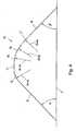
- FIGS. 1 to 3show the side view of keys.
- FIG. 1shows a conventional key to represent the problem.
- FIG. 2shows a key of the type according to the invention in a first embodiment and the FIG. 3 such in a second embodiment.
- the FIG. 4shows the scheme for the construction of a cutting recess according to the invention and
- FIG. 5shows the movement of a core pin head in a cutting cut ..
- the flat keys of the present typeare usually punched out of a metal plate with a thickness of 2 to 3 mm, wherein initially a key blank is made, comprising the key shank 1 with the key tip 19 and the key handle 23.
- the bowl blankstill has unprocessed longitudinal edges 2, 3, as in FIG. 1 are drawn.
- the incision Millsmust be designed so that the key can be easily inserted into the keyway of the cylinder core and pulled out of this again, the strokes of the pin tumblers should be as smooth as possible.
- the incision cutsmust be accurate and defined both in depth and in the extension along the insertion direction 18 of the key, so that on the one hand the position of the pin tumbler is correct and on the other hand the lock can only be locked in the fully inserted position of the key, if so the stop 24 of the key is present at the associated collar of the cylinder core.
- FIGS. 2 and 3show the side view of two keys according to the invention, in which each of the cutting grooves according to the scheme according to FIG. 4 is trained.
- the incision millingthus comprises an inlet flank 9 and an outlet flank 10. These two flanks are inclined relative to the longitudinal edge 3 of the key by the two angles ⁇ and ⁇ , both angles being preferred 45 °.
- the longitudinal edge 3is only present if the key still does not carry any incision milling. By milling, this longitudinal edge 3 is at least milled away in the section of the cutting cut.
- the orientation of the longitudinal edge 3corresponds in any case to the insertion direction of the key, in FIG. 1 designated by the reference numeral 18.
- the inlet edge 9 and outlet edge 10are interconnected by connecting flanks 12, 13, wherein at the bottom of the incision milling as a further connecting edge still the positioning edge 11 is formed, which is just in the insertion direction.
- This Positionierflanke 11positions the spring-biased core pin of the associated pin tumbler.
- the inlet connecting flank 12 lying between the inlet flank 9 and the positioning flank 11has a smaller radius than the outlet connecting flank 13 located between the flattening flank 11 and the flank 10
- FIG. 4 preferred radii of the individual flank sectionsare shown. The centers are of course so according to the drawing down to lay down that the curve pieces with the drawn radii nestle in the overall curve.
- the entrance joint flankhas a radius equal to / less x when x is the variation depth difference 14.
- the variation depth difference xis in FIG. 1 and results from the smallest possible variation depth difference between two depths of the incision cuts. Usually, this difference is about 0.5 mm. With a maximum cutting depth of 5 mm, there are thus 10 depths of variation at each slot cut.
- the outlet connecting flank 13has a larger radius, namely a radius of 3x or larger.
- the outlet connection flank 13consists of a first section 15 having a radius of about 3x, a second section 16 having a radius of about 5x and a third section 17 having a radius of about 4x.
- the insertion behavior of the keyis favorably influenced by the fact that the outlet connecting flank 13 is formed with a relatively large radius, so that the core pin of the cylinder lock is gently led out of the incision groove and is moved without hooks from the positioning edge 11 in the direction of the outlet flank 10 to the insertion the key in the key channel subsequently to be able to immerse again in the next incision milling.
- FIG. 5shows the process in a cutting recess 4 when it slides over a Kemlixkopf 21 over it.
- the associated compression springis designated by the reference numeral 25 and indicated only schematically, wherein also the intermediate housing pin is indicated only schematically.
- FIG. 5engages the Kemuxkopf 21 exactly on the positioning edge 11 and the core pin is in the uppermost position.
- Kemstattkopf 21runs according to the displacement of the key according to arrow 18 to the left initially against the outlet connection edge 13 and the Kemstattkopf is pressed out of the recess cut 4 against the force of the spring 25 due to the relatively large radii of the discharge edge.
- the key according to Fig. 3indicates in addition to the incision milled according to Fig. 2 a key tip 19, the stop edge, which leads to the first incision groove 4, is formed according to the outlet connection flank and outlet edge. This also facilitates the insertion of the key into the key channel.
Landscapes
- Crushing And Grinding (AREA)
- Food-Manufacturing Devices (AREA)
- Surgical Instruments (AREA)
Abstract
Translated fromGermanDescription
Translated fromGermanDie Erfindung betrifft einen Flachschlüssel der an wenigstens einer der beiden Längskanten des Schlüsselschaftes wenigstens eine Einschnittfräsung aufweist, wobei die Einschnittfräsung eine Einlaufflanke und eine Auslaufflanke umfasst, die durch Verbindungsflanken miteinander verbunden sind und durch die, den Grund der Einschnittfräsung bildenden, Verbindungsflanke die Positionierflanke gebildet ist.The invention relates to a flat key which has at least one incision groove on at least one of the two longitudinal edges of the key shank, wherein the incision milling comprises an inlet flank and an outlet flank, which are interconnected by connecting flanks and the positioning flank is formed by the connecting flank forming the base of the incision groove ,
Derartige Flachschlüssel dienen zum Sperren von Zylinderschlössem, wobei die Einschnittfräsungen entweder an einer oder an beiden Längskanten des Flachschlüssels vorgesehen sind. Die zugehörigen Zylinderschlösser weisen in bekannter Weise einen Schlüsselkanal auf, in den der Flachschlüssel bis zum Anschlag eingeschoben werden kann. Im Zylinderkern des Zylinderschlosses sind die Kernstifte als Bestandteil der zwei- oder mehrgeteilten Stiftzuhaltungen verschieblich angeordnet, wobei die Einschnittfräsungen des Schlüssels so tief sein müssen, dass die zugehörige Teilung des Kemstiftes ein Verdrehen des Zylinderkerns im Zylindergehäuse zulässt. Die Funktion von Schliesszylindern ist seit Ende des 19. Jahrhunderts Stand der Technik und bedarf keiner weiteren Erläuterung.Such flat keys are used to lock Zylinderschlössem, the Einschnittfräsungen are provided either on one or both longitudinal edges of the flat key. The associated cylinder locks have a keyway in a known manner, in which the flat key can be inserted to the stop. In the cylinder core of the cylinder lock, the core pins are slidably disposed as part of the two or more divided pin tumblers, the incision Milling the key must be so deep that the associated pitch of Kemstiftes allows rotation of the cylinder core in the cylinder housing. The function of lock cylinders has been state of the art since the end of the 19th century and needs no further explanation.
Ein Flachschlüssel umfasst einen Schlüsselschaft, dessen beide Längskanten in Einschubrichtung des Schlüssels liegen. Zumindest eine der beiden Längskanten weist einer oder mehrere hintereinander angeordnete Einschnittfräsungen auf, wobei heute zumeist fünf oder sechs Einschnittfräsungen an einer Längskante vorgesehen sind. Im Falle von sogenannten Wendeschlüsseln tragen beide Längskanten die gleiche Aufeinanderfolge von Einschnittfräsungen, damit der Schlüssel in jeweils 180° verdrehter Lage eingeschoben werden kann.A flat key comprises a key shank whose two longitudinal edges lie in the insertion direction of the key. At least one of the two longitudinal edges has one or more incision grooves arranged one behind the other, wherein today usually five or six incision grooves are provided on a longitudinal edge. In the case of so-called reversible keys, both longitudinal edges carry the same sequence of incision cuts, so that the key can be inserted in a position rotated by 180 ° in each case.
Es versteht sich von selbst, dass die Längskanten bei Anordnung von Einschnittfräsungen unterbrochen sind und bei durchgehender Anordnung von Einschnittfräsungen nur in einem kleinen Teilbereich stehen bleiben.It goes without saying that the longitudinal edges are interrupted in the arrangement of incision cuts and remain in a continuous arrangement of incision milled only in a small portion.
Jede Einschnittfräsung verfügt über eine Einlaufflanke und eine Auslaufflanke. Beide Flanken sind durch eine Positionierflanke verbunden, wobei diese Positionierflanke den Grund der Einschnittfräsung bildet und für den zugehörigen Kernstift des Zylinderschlosses die Positionierung bestimmt.Each incision groove has an inlet flank and an outlet flank. Both flanks are connected by a positioning edge, wherein this positioning edge forms the bottom of the incision milling and determines the positioning of the associated core pin of the cylinder lock.
Ein schon länger bekanntes Problem bei derartigen Schlüsseln liegt darin, dass das Schlüsselmaterial an jenen Stellen leicht einreißt und sogar abbrechen kann, an denen die Einschnittfräsungen tief ausgebildet sind. Dieser Nachteil wird dadurch hervorgerufen, dass scharfkantige Fräskanten oder kleine Radien vorgesehen werden, wenn die Fräsung durchgeführt wird. Dieses Problem soll gelöst werden.A long-standing problem with such keys is that the key material easily tears and even breaks at those locations where the sipe cuts are deeply formed. This disadvantage is caused by the fact that sharp-edged Fräskanten or small radii are provided when the milling is performed. This problem should be solved.
Eine weitere Aufgabe bei derartigen Flachschlüsseln liegt darin, das Einschubverhalten des Schlüssels in den Schlüsselkanal komfortabel auszugestalten. Zu steile Flanken der Einschnittfräsungen bewirken ein schlechtes Einschubverhalten und es kommt sogar zu einem Steckenbleiben des Schlüssels. Die Winkelstellung der Einlaufflanken und Auslaufflanken soll etwa 45° betragen, um die sonstigen geometrischen Verhältnisse derartiger Flachschlüssel beibehalten zu können. Im Übrigen müssen die Einschnittfräsungen so ausgebildet sein, dass der Schlüssel nur in einer genau definierten Lage die Sperre zulässt und vermeidet, dass der Zylinderkern verdreht werden kann, noch bevor der Schlüssel zur Gänze eingeschoben ist. Zu flache Flanken können hierbei Probleme machen.Another object of such flat keys is to make the insertion behavior of the key in the key channel comfortable. To steep flanks of the cutting cuts cause poor insertion behavior and it even comes to a sticking of the key. The angular position of the inlet flanks and outlet edges should be about 45 ° in order to maintain the other geometric conditions of such flat key can. Incidentally, the incision milling must be designed so that the key only in a well-defined position allows the lock and avoids that the cylinder core can be twisted even before the key is fully inserted. Too low flanks can cause problems here.
Gemäß Erfindung sollen alle diese Nachteile vermieden werden.According to the invention, all these disadvantages are to be avoided.
Der erfindungsgemäße Schlüssel istdadurch gekennzeichnet, dass die zwischen der Einlaufflanke und der Positionierflanke liegende Einlaufverbindungsflanke einen kleineren Radius aufweist, als die zwischen der Positionierungsflanke und der Auslaufflanke liegende Auslaufverbindungsflanke.The key according to the invention ischaracterized in that the inlet connecting flank located between the inlet flank and the positioning flank has a smaller radius than the outlet connecting flank located between the positioning flank and the outlet flank.
Weitere vorteilhafte Merkmale sind den Ansprüchen, der Beschreibung und den Zeichnungen zu entnehmen.Further advantageous features are described in the claims, the description and the drawings.
Gemäß Erfindung wird also eine Einlaufverbindungsflanke mit einem kleineren Radius und nach der Positionierflanke eine Auslaufverbindungsflanke mit einem oder mehreren größeren Radien vorgesehen. Damit ist sichergestellt, dass schon die Einlaufverbindungsflanke über einen Radius verfügt, der ein Einreißen des Schlüsselmaterials verhindert. Weiters wird eine Auslaufverbindungsflanke gebildet, die zufolge eines oder mehrerer größeren Radien einerseits das Einreißen des Materials verhindert und andererseits den federbelasteten Zylinderkernstift weich aus der Einschnittfräsung herausschiebt, wenn der Schlüssel verschoben wird.According to the invention, therefore, an inlet connecting flank with a smaller radius and after the positioning flank an outlet connecting flank with one or more larger radii is provided. This ensures that even the inlet connecting flank has a radius that prevents tearing of the key material. Furthermore, an outlet connection flank is formed which, on the one hand, prevents tearing of the material due to one or more larger radii and, on the other hand, gently pushes out the spring-loaded cylinder core pin from the incision groove when the key is displaced.
Nachfolgend wird sowohl der Stand der Technik als auch die Erfindung anhand von zwei Ausführungsbeispielen näher beschrieben.In the following, both the prior art and the invention will be described in more detail with reference to two exemplary embodiments.
Die
Die Flachschlüssel der vorliegenden Art sind üblicherweise aus einer Metallplatte mit einer Dicke von 2 bis 3 mm ausgestanzt, wobei vorerst ein Schlüsselrohling hergestellt wird, der den Schlüsselschaft 1 mit der Schlüsselspitze 19 und den Schlüsselgriff 23 umfasst. Der Schüsselrohling verfügt noch über unbearbeitete Längskanten 2, 3, wie sie in
Die
Die Einlaufflanke 9 und Auslaufflanke 10 sind durch Verbindungsflanken 12, 13 miteinander verbunden, wobei am Grund der Einschnittfräsung als weitere Verbindungsflanke noch die Positionierflanke 11 ausgebildet ist, die gerade in Einschubrichtung steht. Diese Positionierflanke 11 positioniert den unter Federdruck vorgespannten Kernstift der zugehörigen Stiftzuhaltung.The
Gemäß vorliegender Erfindung weist die zwischen der Einlaufflanke 9 und der Positionierflanke 11 liegende Einlaufverbindungsflanke 12 einen kleineren Radius auf, als die zwischen der Posftionierflanke 11 und der Auslaufflanke 10 liegende Auslaufverbindungsflanke 13. In
Die Einlaufverbindungsflanke hat einen Radius von gleich/kleiner x, wenn x die Variationstiefendifferenz 14 ist. Die Variationstiefendifferenz x ist in
Gemäß
Diese gewählten Fräsradien ermöglichen es, die sonst üblichen scharfen Kanten in der Einschnittfräsung zu vermeiden, sodass sich das Problem der Materialschwächung nicht stellt. Andererseits wird das Einschubverhalten des Schlüssels dadurch günstig beeinflusst, dass die Auslaufverbindungsflanke 13 mit einem relativ großen Radius ausgebildet ist, sodass der Kernstift des Zylinderschlosses sanft aus der Einschnittfräsung herausgeführt wird und ohne Haken von der Positionierflanke 11 in Richtung Auslaufflanke 10 bewegt wird, um beim Einschieben des Schlüssels in den Schlüsselkanal nachfolgend wieder in die nächste Einschnittfräsung eintauchen zu können.These selected milling radii make it possible to avoid the otherwise common sharp edges in the incision milling, so that the problem of material weakening does not stop. On the other hand, the insertion behavior of the key is favorably influenced by the fact that the
In der Stellung a) der
In der Stellung b) läuft der Kemstiftkopf 21 zufolge des Verschiebens des Schlüssels gemäß Pfeil 18 nach links vorerst gegen die Auslaufverbindungsflanke 13 und der Kemstiftkopf wird zufolge der relativ großen Radien der Auslaufflanke 13 sanft aus der Einschnittfräsung 4 gegen die Kraft der Feder 25 herausgedrückt.In the position b) Kemstiftkopf 21 runs according to the displacement of the key according to
Der Schlüssel gemäß
Claims (11)
Translated fromGermanPriority Applications (1)
| Application Number | Priority Date | Filing Date | Title |
|---|---|---|---|
| PL09009005TPL2146030T3 (en) | 2008-07-15 | 2009-07-10 | Flat key |
Applications Claiming Priority (1)
| Application Number | Priority Date | Filing Date | Title |
|---|---|---|---|
| AT0109708AAT506700B1 (en) | 2008-07-15 | 2008-07-15 | FLAT KEY |
Publications (2)
| Publication Number | Publication Date |
|---|---|
| EP2146030A1true EP2146030A1 (en) | 2010-01-20 |
| EP2146030B1 EP2146030B1 (en) | 2011-11-30 |
Family
ID=41170911
Family Applications (1)
| Application Number | Title | Priority Date | Filing Date |
|---|---|---|---|
| EP09009005ANot-in-forceEP2146030B1 (en) | 2008-07-15 | 2009-07-10 | Flat key |
Country Status (4)
| Country | Link |
|---|---|
| EP (1) | EP2146030B1 (en) |
| AT (2) | AT506700B1 (en) |
| DK (1) | DK2146030T3 (en) |
| PL (1) | PL2146030T3 (en) |
Cited By (5)
| Publication number | Priority date | Publication date | Assignee | Title |
|---|---|---|---|---|
| EP2149657B1 (en)* | 2008-07-29 | 2013-03-27 | Aug. Winkhaus GmbH & Co. KG | Key for a lock cylinder and blank for such a key |
| EP2264264A3 (en)* | 2009-06-18 | 2014-03-19 | C. Ed. Schulte Gesellschaft mit beschränkter Haftung Zylinderschlossfabrik | Locking device and key for a locking device |
| EP3696353A1 (en)* | 2019-02-14 | 2020-08-19 | Aug. Winkhaus GmbH & Co. KG | Locking device with a key and a locking cylinder |
| EP3696352A1 (en)* | 2019-02-14 | 2020-08-19 | Aug. Winkhaus GmbH & Co. KG | Key for a locking cylinder |
| US10957355B2 (en) | 2018-02-28 | 2021-03-23 | International Business Machines Corporation | Authenticating digital recordings |
Families Citing this family (1)
| Publication number | Priority date | Publication date | Assignee | Title |
|---|---|---|---|---|
| DE102015106198A1 (en) | 2015-04-22 | 2016-10-27 | C.Ed. Schulte Gesellschaft mit beschränkter Haftung Zylinderschlossfabrik | closing device |
Citations (4)
| Publication number | Priority date | Publication date | Assignee | Title |
|---|---|---|---|---|
| EP0992642A1 (en)* | 1998-10-10 | 2000-04-12 | BKS GmbH | Securitykey |
| EP1577469A2 (en)* | 2004-03-19 | 2005-09-21 | Aug. Winkhaus GmbH & Co. KG | Key |
| EP1746226A2 (en)* | 2005-07-19 | 2007-01-24 | Aug. Winkhaus GmbH & Co. KG | Key and lock cylinder for a key |
| FR2896817A3 (en)* | 2006-02-02 | 2007-08-03 | Evva Werke | Cylindrical lock comprises cylindrical core pins formed on the end protruding into the key channel as scanning protrusions which are narrower than the diameter of the core pins and are aligned in the longitudinal direction of the channel |
- 2008
- 2008-07-15ATAT0109708Apatent/AT506700B1/ennot_activeIP Right Cessation
- 2009
- 2009-07-10EPEP09009005Apatent/EP2146030B1/ennot_activeNot-in-force
- 2009-07-10PLPL09009005Tpatent/PL2146030T3/enunknown
- 2009-07-10DKDK09009005.1Tpatent/DK2146030T3/enactive
- 2009-07-10ATAT09009005Tpatent/ATE535666T1/enactive
Patent Citations (4)
| Publication number | Priority date | Publication date | Assignee | Title |
|---|---|---|---|---|
| EP0992642A1 (en)* | 1998-10-10 | 2000-04-12 | BKS GmbH | Securitykey |
| EP1577469A2 (en)* | 2004-03-19 | 2005-09-21 | Aug. Winkhaus GmbH & Co. KG | Key |
| EP1746226A2 (en)* | 2005-07-19 | 2007-01-24 | Aug. Winkhaus GmbH & Co. KG | Key and lock cylinder for a key |
| FR2896817A3 (en)* | 2006-02-02 | 2007-08-03 | Evva Werke | Cylindrical lock comprises cylindrical core pins formed on the end protruding into the key channel as scanning protrusions which are narrower than the diameter of the core pins and are aligned in the longitudinal direction of the channel |
Cited By (5)
| Publication number | Priority date | Publication date | Assignee | Title |
|---|---|---|---|---|
| EP2149657B1 (en)* | 2008-07-29 | 2013-03-27 | Aug. Winkhaus GmbH & Co. KG | Key for a lock cylinder and blank for such a key |
| EP2264264A3 (en)* | 2009-06-18 | 2014-03-19 | C. Ed. Schulte Gesellschaft mit beschränkter Haftung Zylinderschlossfabrik | Locking device and key for a locking device |
| US10957355B2 (en) | 2018-02-28 | 2021-03-23 | International Business Machines Corporation | Authenticating digital recordings |
| EP3696353A1 (en)* | 2019-02-14 | 2020-08-19 | Aug. Winkhaus GmbH & Co. KG | Locking device with a key and a locking cylinder |
| EP3696352A1 (en)* | 2019-02-14 | 2020-08-19 | Aug. Winkhaus GmbH & Co. KG | Key for a locking cylinder |
Also Published As
| Publication number | Publication date |
|---|---|
| ATE535666T1 (en) | 2011-12-15 |
| PL2146030T3 (en) | 2012-05-31 |
| AT506700A4 (en) | 2009-11-15 |
| AT506700B1 (en) | 2009-11-15 |
| EP2146030B1 (en) | 2011-11-30 |
| DK2146030T3 (en) | 2012-03-26 |
Similar Documents
| Publication | Publication Date | Title |
|---|---|---|
| EP0335069B1 (en) | Flat key for cylinder locks, and cylinder lock for this key | |
| EP2390030B1 (en) | Method for profiling a flat key and the flat key manufactured according to the method | |
| EP2146030B1 (en) | Flat key | |
| DE102009050129A1 (en) | locking system | |
| WO2004009937A1 (en) | Security key and locking cylinder | |
| EP4047161A1 (en) | Key, key and locking cylinder | |
| EP2803793A2 (en) | Lock cylinder with pulling pin which engages with a protrusion extending from the broad side of the key | |
| EP2536902A1 (en) | Locking system, key and key blank | |
| DE102005036113A1 (en) | Flat key for cylinder lock has chest with grooves, whereby one slot flank encloses center plane of flat key at angle less than ninety degrees and other slot flank encloses center plane of flat key at slightly more than ninety degrees | |
| DE2516340C3 (en) | ||
| WO2006108656A2 (en) | Cylinder lock and flat key | |
| DE2135106C3 (en) | Locking device with cylinder core and flat key | |
| AT5395U1 (en) | PROFILE SYSTEM FOR CROSS-SECTION TRAINING OF FLAT KEYS | |
| DE102013103790A1 (en) | Coding via locking bar | |
| DE202006003869U1 (en) | Cylinder lock and flat key | |
| EP1068415B1 (en) | Cylinder lock with flat key | |
| AT521007B1 (en) | PIN CYLINDER KEY SYSTEM AND KEY FOR IT | |
| DE20105519U1 (en) | Cylinder lock with cylinder housing and flat key for a cylinder lock | |
| AT500638B1 (en) | Flat key for cylinder lock has chest with grooves, whereby one slot flank encloses center plane of flat key at angle less than ninety degrees and other slot flank encloses center plane of flat key at slightly more than ninety degrees | |
| AT525384B1 (en) | Flat keys, key blanks, processes for their production and lock cylinders | |
| EP4204648B1 (en) | Flat key for a cylinder lock | |
| DE810956C (en) | Cylinder lock | |
| AT407547B (en) | Flat key and cylinder lock | |
| EP2053184A2 (en) | Cylinder lock with changeable key combination | |
| AT503051B1 (en) | Cylinder lock, has set of control profile slots brought in interference at flat sides of key and control plate is in interference with locking recess in cylinder housing in normal position and key is adjustable in core in release position |
Legal Events
| Date | Code | Title | Description |
|---|---|---|---|
| PUAI | Public reference made under article 153(3) epc to a published international application that has entered the european phase | Free format text:ORIGINAL CODE: 0009012 | |
| AK | Designated contracting states | Kind code of ref document:A1 Designated state(s):AT BE BG CH CY CZ DE DK EE ES FI FR GB GR HR HU IE IS IT LI LT LU LV MC MK MT NL NO PL PT RO SE SI SK SM TR | |
| AX | Request for extension of the european patent | Extension state:AL BA RS | |
| 17P | Request for examination filed | Effective date:20100505 | |
| RAP1 | Party data changed (applicant data changed or rights of an application transferred) | Owner name:EVVA SICHERHEITSTECHNOLOGIE GMBH | |
| GRAP | Despatch of communication of intention to grant a patent | Free format text:ORIGINAL CODE: EPIDOSNIGR1 | |
| GRAS | Grant fee paid | Free format text:ORIGINAL CODE: EPIDOSNIGR3 | |
| GRAA | (expected) grant | Free format text:ORIGINAL CODE: 0009210 | |
| AK | Designated contracting states | Kind code of ref document:B1 Designated state(s):AT BE BG CH CY CZ DE DK EE ES FI FR GB GR HR HU IE IS IT LI LT LU LV MC MK MT NL NO PL PT RO SE SI SK SM TR | |
| REG | Reference to a national code | Ref country code:CH Ref legal event code:EP Ref country code:GB Ref legal event code:FG4D Free format text:NOT ENGLISH | |
| REG | Reference to a national code | Ref country code:IE Ref legal event code:FG4D Free format text:LANGUAGE OF EP DOCUMENT: GERMAN | |
| REG | Reference to a national code | Ref country code:DE Ref legal event code:R096 Ref document number:502009002044 Country of ref document:DE Effective date:20120301 | |
| REG | Reference to a national code | Ref country code:NL Ref legal event code:T3 | |
| REG | Reference to a national code | Ref country code:SE Ref legal event code:TRGR | |
| REG | Reference to a national code | Ref country code:DK Ref legal event code:T3 | |
| LTIE | Lt: invalidation of european patent or patent extension | Effective date:20111130 | |
| PG25 | Lapsed in a contracting state [announced via postgrant information from national office to epo] | Ref country code:IS Free format text:LAPSE BECAUSE OF FAILURE TO SUBMIT A TRANSLATION OF THE DESCRIPTION OR TO PAY THE FEE WITHIN THE PRESCRIBED TIME-LIMIT Effective date:20120330 Ref country code:LT Free format text:LAPSE BECAUSE OF FAILURE TO SUBMIT A TRANSLATION OF THE DESCRIPTION OR TO PAY THE FEE WITHIN THE PRESCRIBED TIME-LIMIT Effective date:20111130 Ref country code:NO Free format text:LAPSE BECAUSE OF FAILURE TO SUBMIT A TRANSLATION OF THE DESCRIPTION OR TO PAY THE FEE WITHIN THE PRESCRIBED TIME-LIMIT Effective date:20120229 | |
| PG25 | Lapsed in a contracting state [announced via postgrant information from national office to epo] | Ref country code:GR Free format text:LAPSE BECAUSE OF FAILURE TO SUBMIT A TRANSLATION OF THE DESCRIPTION OR TO PAY THE FEE WITHIN THE PRESCRIBED TIME-LIMIT Effective date:20120301 Ref country code:PT Free format text:LAPSE BECAUSE OF FAILURE TO SUBMIT A TRANSLATION OF THE DESCRIPTION OR TO PAY THE FEE WITHIN THE PRESCRIBED TIME-LIMIT Effective date:20120330 Ref country code:LV Free format text:LAPSE BECAUSE OF FAILURE TO SUBMIT A TRANSLATION OF THE DESCRIPTION OR TO PAY THE FEE WITHIN THE PRESCRIBED TIME-LIMIT Effective date:20111130 Ref country code:HR Free format text:LAPSE BECAUSE OF FAILURE TO SUBMIT A TRANSLATION OF THE DESCRIPTION OR TO PAY THE FEE WITHIN THE PRESCRIBED TIME-LIMIT Effective date:20111130 Ref country code:SI Free format text:LAPSE BECAUSE OF FAILURE TO SUBMIT A TRANSLATION OF THE DESCRIPTION OR TO PAY THE FEE WITHIN THE PRESCRIBED TIME-LIMIT Effective date:20111130 | |
| REG | Reference to a national code | Ref country code:PL Ref legal event code:T3 | |
| REG | Reference to a national code | Ref country code:SK Ref legal event code:T3 Ref document number:E 11404 Country of ref document:SK | |
| REG | Reference to a national code | Ref country code:IE Ref legal event code:FD4D | |
| PG25 | Lapsed in a contracting state [announced via postgrant information from national office to epo] | Ref country code:CY Free format text:LAPSE BECAUSE OF FAILURE TO SUBMIT A TRANSLATION OF THE DESCRIPTION OR TO PAY THE FEE WITHIN THE PRESCRIBED TIME-LIMIT Effective date:20111130 | |
| PG25 | Lapsed in a contracting state [announced via postgrant information from national office to epo] | Ref country code:IE Free format text:LAPSE BECAUSE OF FAILURE TO SUBMIT A TRANSLATION OF THE DESCRIPTION OR TO PAY THE FEE WITHIN THE PRESCRIBED TIME-LIMIT Effective date:20111130 Ref country code:BG Free format text:LAPSE BECAUSE OF FAILURE TO SUBMIT A TRANSLATION OF THE DESCRIPTION OR TO PAY THE FEE WITHIN THE PRESCRIBED TIME-LIMIT Effective date:20120229 Ref country code:EE Free format text:LAPSE BECAUSE OF FAILURE TO SUBMIT A TRANSLATION OF THE DESCRIPTION OR TO PAY THE FEE WITHIN THE PRESCRIBED TIME-LIMIT Effective date:20111130 | |
| PG25 | Lapsed in a contracting state [announced via postgrant information from national office to epo] | Ref country code:RO Free format text:LAPSE BECAUSE OF FAILURE TO SUBMIT A TRANSLATION OF THE DESCRIPTION OR TO PAY THE FEE WITHIN THE PRESCRIBED TIME-LIMIT Effective date:20111130 | |
| PLBE | No opposition filed within time limit | Free format text:ORIGINAL CODE: 0009261 | |
| STAA | Information on the status of an ep patent application or granted ep patent | Free format text:STATUS: NO OPPOSITION FILED WITHIN TIME LIMIT | |
| 26N | No opposition filed | Effective date:20120831 | |
| REG | Reference to a national code | Ref country code:DE Ref legal event code:R097 Ref document number:502009002044 Country of ref document:DE Effective date:20120831 | |
| PG25 | Lapsed in a contracting state [announced via postgrant information from national office to epo] | Ref country code:MK Free format text:LAPSE BECAUSE OF FAILURE TO SUBMIT A TRANSLATION OF THE DESCRIPTION OR TO PAY THE FEE WITHIN THE PRESCRIBED TIME-LIMIT Effective date:20111130 Ref country code:MC Free format text:LAPSE BECAUSE OF NON-PAYMENT OF DUE FEES Effective date:20120731 | |
| PG25 | Lapsed in a contracting state [announced via postgrant information from national office to epo] | Ref country code:ES Free format text:LAPSE BECAUSE OF FAILURE TO SUBMIT A TRANSLATION OF THE DESCRIPTION OR TO PAY THE FEE WITHIN THE PRESCRIBED TIME-LIMIT Effective date:20120311 | |
| PG25 | Lapsed in a contracting state [announced via postgrant information from national office to epo] | Ref country code:FI Free format text:LAPSE BECAUSE OF FAILURE TO SUBMIT A TRANSLATION OF THE DESCRIPTION OR TO PAY THE FEE WITHIN THE PRESCRIBED TIME-LIMIT Effective date:20111130 | |
| PG25 | Lapsed in a contracting state [announced via postgrant information from national office to epo] | Ref country code:MT Free format text:LAPSE BECAUSE OF FAILURE TO SUBMIT A TRANSLATION OF THE DESCRIPTION OR TO PAY THE FEE WITHIN THE PRESCRIBED TIME-LIMIT Effective date:20111130 | |
| REG | Reference to a national code | Ref country code:CH Ref legal event code:PL | |
| PG25 | Lapsed in a contracting state [announced via postgrant information from national office to epo] | Ref country code:CH Free format text:LAPSE BECAUSE OF NON-PAYMENT OF DUE FEES Effective date:20130731 Ref country code:TR Free format text:LAPSE BECAUSE OF FAILURE TO SUBMIT A TRANSLATION OF THE DESCRIPTION OR TO PAY THE FEE WITHIN THE PRESCRIBED TIME-LIMIT Effective date:20111130 Ref country code:LI Free format text:LAPSE BECAUSE OF NON-PAYMENT OF DUE FEES Effective date:20130731 | |
| PG25 | Lapsed in a contracting state [announced via postgrant information from national office to epo] | Ref country code:LU Free format text:LAPSE BECAUSE OF NON-PAYMENT OF DUE FEES Effective date:20120710 Ref country code:SM Free format text:LAPSE BECAUSE OF FAILURE TO SUBMIT A TRANSLATION OF THE DESCRIPTION OR TO PAY THE FEE WITHIN THE PRESCRIBED TIME-LIMIT Effective date:20111130 | |
| PG25 | Lapsed in a contracting state [announced via postgrant information from national office to epo] | Ref country code:HU Free format text:LAPSE BECAUSE OF FAILURE TO SUBMIT A TRANSLATION OF THE DESCRIPTION OR TO PAY THE FEE WITHIN THE PRESCRIBED TIME-LIMIT Effective date:20090710 | |
| PGFP | Annual fee paid to national office [announced via postgrant information from national office to epo] | Ref country code:PL Payment date:20140522 Year of fee payment:6 | |
| PGFP | Annual fee paid to national office [announced via postgrant information from national office to epo] | Ref country code:NL Payment date:20140721 Year of fee payment:6 Ref country code:CZ Payment date:20140704 Year of fee payment:6 Ref country code:DK Payment date:20140721 Year of fee payment:6 Ref country code:DE Payment date:20140711 Year of fee payment:6 | |
| PGFP | Annual fee paid to national office [announced via postgrant information from national office to epo] | Ref country code:AT Payment date:20140602 Year of fee payment:6 Ref country code:FR Payment date:20140721 Year of fee payment:6 Ref country code:SK Payment date:20140707 Year of fee payment:6 Ref country code:SE Payment date:20140721 Year of fee payment:6 Ref country code:GB Payment date:20140721 Year of fee payment:6 | |
| PGFP | Annual fee paid to national office [announced via postgrant information from national office to epo] | Ref country code:IT Payment date:20140724 Year of fee payment:6 | |
| PGFP | Annual fee paid to national office [announced via postgrant information from national office to epo] | Ref country code:BE Payment date:20140722 Year of fee payment:6 | |
| REG | Reference to a national code | Ref country code:DE Ref legal event code:R119 Ref document number:502009002044 Country of ref document:DE | |
| REG | Reference to a national code | Ref country code:DK Ref legal event code:EBP Effective date:20150731 | |
| REG | Reference to a national code | Ref country code:SE Ref legal event code:EUG Ref country code:SK Ref legal event code:MM4A Ref document number:E 11404 Country of ref document:SK Effective date:20150710 | |
| REG | Reference to a national code | Ref country code:AT Ref legal event code:MM01 Ref document number:535666 Country of ref document:AT Kind code of ref document:T Effective date:20150710 | |
| GBPC | Gb: european patent ceased through non-payment of renewal fee | Effective date:20150710 | |
| REG | Reference to a national code | Ref country code:NL Ref legal event code:MM Effective date:20150801 | |
| PG25 | Lapsed in a contracting state [announced via postgrant information from national office to epo] | Ref country code:GB Free format text:LAPSE BECAUSE OF NON-PAYMENT OF DUE FEES Effective date:20150710 Ref country code:CZ Free format text:LAPSE BECAUSE OF NON-PAYMENT OF DUE FEES Effective date:20150710 Ref country code:IT Free format text:LAPSE BECAUSE OF NON-PAYMENT OF DUE FEES Effective date:20150710 Ref country code:DE Free format text:LAPSE BECAUSE OF NON-PAYMENT OF DUE FEES Effective date:20160202 Ref country code:SK Free format text:LAPSE BECAUSE OF NON-PAYMENT OF DUE FEES Effective date:20150710 | |
| REG | Reference to a national code | Ref country code:FR Ref legal event code:ST Effective date:20160331 | |
| PG25 | Lapsed in a contracting state [announced via postgrant information from national office to epo] | Ref country code:FR Free format text:LAPSE BECAUSE OF NON-PAYMENT OF DUE FEES Effective date:20150731 Ref country code:SE Free format text:LAPSE BECAUSE OF NON-PAYMENT OF DUE FEES Effective date:20150711 Ref country code:NL Free format text:LAPSE BECAUSE OF NON-PAYMENT OF DUE FEES Effective date:20150801 Ref country code:AT Free format text:LAPSE BECAUSE OF NON-PAYMENT OF DUE FEES Effective date:20150710 | |
| PG25 | Lapsed in a contracting state [announced via postgrant information from national office to epo] | Ref country code:DK Free format text:LAPSE BECAUSE OF NON-PAYMENT OF DUE FEES Effective date:20150731 | |
| PG25 | Lapsed in a contracting state [announced via postgrant information from national office to epo] | Ref country code:PL Free format text:LAPSE BECAUSE OF NON-PAYMENT OF DUE FEES Effective date:20150710 | |
| PG25 | Lapsed in a contracting state [announced via postgrant information from national office to epo] | Ref country code:BE Free format text:LAPSE BECAUSE OF NON-PAYMENT OF DUE FEES Effective date:20150731 |