EP2145446B1 - Synchronization test for device authentication - Google Patents
Synchronization test for device authenticationDownload PDFInfo
- Publication number
- EP2145446B1 EP2145446B1EP08732957.9AEP08732957AEP2145446B1EP 2145446 B1EP2145446 B1EP 2145446B1EP 08732957 AEP08732957 AEP 08732957AEP 2145446 B1EP2145446 B1EP 2145446B1
- Authority
- EP
- European Patent Office
- Prior art keywords
- time
- actuation
- indication
- user input
- input device
- Prior art date
- Legal status (The legal status is an assumption and is not a legal conclusion. Google has not performed a legal analysis and makes no representation as to the accuracy of the status listed.)
- Not-in-force
Links
Images


Classifications
- H—ELECTRICITY
- H04—ELECTRIC COMMUNICATION TECHNIQUE
- H04W—WIRELESS COMMUNICATION NETWORKS
- H04W12/00—Security arrangements; Authentication; Protecting privacy or anonymity
- H04W12/06—Authentication
- G—PHYSICS
- G06—COMPUTING OR CALCULATING; COUNTING
- G06F—ELECTRIC DIGITAL DATA PROCESSING
- G06F21/00—Security arrangements for protecting computers, components thereof, programs or data against unauthorised activity
- G06F21/30—Authentication, i.e. establishing the identity or authorisation of security principals
- G06F21/31—User authentication
- G06F21/34—User authentication involving the use of external additional devices, e.g. dongles or smart cards
- G06F21/35—User authentication involving the use of external additional devices, e.g. dongles or smart cards communicating wirelessly
- G—PHYSICS
- G06—COMPUTING OR CALCULATING; COUNTING
- G06F—ELECTRIC DIGITAL DATA PROCESSING
- G06F21/00—Security arrangements for protecting computers, components thereof, programs or data against unauthorised activity
- G06F21/30—Authentication, i.e. establishing the identity or authorisation of security principals
- G06F21/31—User authentication
- G06F21/40—User authentication by quorum, i.e. whereby two or more security principals are required
- H—ELECTRICITY
- H04—ELECTRIC COMMUNICATION TECHNIQUE
- H04L—TRANSMISSION OF DIGITAL INFORMATION, e.g. TELEGRAPHIC COMMUNICATION
- H04L63/00—Network architectures or network communication protocols for network security
- H04L63/08—Network architectures or network communication protocols for network security for authentication of entities
- H—ELECTRICITY
- H04—ELECTRIC COMMUNICATION TECHNIQUE
- H04W—WIRELESS COMMUNICATION NETWORKS
- H04W12/00—Security arrangements; Authentication; Protecting privacy or anonymity
- H04W12/50—Secure pairing of devices
- H—ELECTRICITY
- H04—ELECTRIC COMMUNICATION TECHNIQUE
- H04W—WIRELESS COMMUNICATION NETWORKS
- H04W88/00—Devices specially adapted for wireless communication networks, e.g. terminals, base stations or access point devices
- H04W88/02—Terminal devices
- H—ELECTRICITY
- H04—ELECTRIC COMMUNICATION TECHNIQUE
- H04W—WIRELESS COMMUNICATION NETWORKS
- H04W12/00—Security arrangements; Authentication; Protecting privacy or anonymity
- H04W12/60—Context-dependent security
- H04W12/68—Gesture-dependent or behaviour-dependent
Definitions
- This applicationrelates generally to wireless communication and more specifically, but not exclusively, to synchronization tests for device authentication.
- Wireless devicesmay employ a pairing process in an attempt to form a level of trust with one another in conjunction with authenticating with each other or exchanging cryptographic keys that may be used for services that are protected by cryptographic techniques.
- authentication between two devicesmay involve the exchange of a passcode between the devices.
- such a proceduremay involve the use of a sophisticated user interface for passcode input.
- the associated provisioning costmay be relatively high.
- a typical passcode used by usersmay be four to eight digits long, which may not be strong enough to prevent the security of the devices from being compromised by conventional cryptanalysis.
- Bluetooth V2.1proposes using elliptic curve Diffie-Hellman for key exchange.
- device authenticationmay be based on numeric comparison or passkey entry.
- these methodsmay utilize a sophisticated user interface and may be relatively susceptible to man-in-the-middle attacks.
- Near field communication technologyalso may be used for device authentication.
- near field communication devicesmay be designed to perform a handshake only when they are brought within a defined "touching" distance of each other. It may be possible, however, to design a near field communication device with a custom antenna that extends the working distance for the handshake. In this case, an unauthorized person or device may be able to authenticate with another device from relatively long range thereby thwarting the security otherwise provided the requirement of relatively close proximity of the devices. Consequently, authentication that is based on a relatively small touching distance as provided by near field communication may not provide a sufficient level of security.
- the disclosurerelates in some aspects authenticating devices or performing other similar operations based on the ability of a human to synchronize the movements of his or her fingers.
- a personmay be able to press or release two buttons in a simultaneous manner or in a substantially simultaneous manner.
- itmay be relatively difficult for an onlooker to anticipate and synchronize to the timings of the finger movements of the other person. Consequently, a pairing procedure for two wireless devices may involve a synchronization test that is based on the relative timing of actuations of input devices on each of the wireless devices.
- a pair of wireless devicesmay be deemed trustable with respect to one another if the same person is physically holding the two wireless devices. Consequently, when two wireless devices being held by the same person communicate with each other, a message sent by a first one of the wireless devices relating to a local synchronization event (e.g., actuation of a user input device) at the first device may be deemed trustable by a second one of the wireless devices that receives the message. To ensure that the same person is holding the devices, the receiving device verifies that the timing of the received message is substantially synchronized with a similar local synchronization event at the second device. Consequently, an authentication or other similar procedure may involve determining whether an input device on a first device is actuated (e.g., depressed and/or released) at substantially the same time or times that an input device on a second device is actuated.
- actuatione.g., actuation of a user input device
- the disclosurerelates in some aspects to a synchronization test that involves determining whether actuations of user input devices on two different wireless devices occurred within a defined time interval with respect to one another.
- a usermay be instructed to simultaneously actuate a user input device on each wireless device.
- a first one of the wireless devicesmay determine the actuation time associated with a second one of the wireless devices based on the time at which the first device receives a message from the second device relating to the actuation of the second device.
- the first devicemay thus compare the actuation time of its user input device with the time it received the message from the second device.
- the second devicemay perform a similar synchronization test.
- the devicesmay authenticate one another.
- a cryptographic key agreement schememay be employed in conjunction with the synchronization tests.
- the synchronization testsmay be based on the timings of more than one actuation of each user input device.
- the disclosurerelates in some aspects to a synchronization test that involves comparing time intervals between multiple actuations of user input devices on two different wireless devices.
- a usermay be instructed to simultaneously actuate a user input device on each wireless device in a repeated (e.g., random) manner. That is, the user may repeatedly actuate each user input device at the same time. In this way a set of time intervals corresponding to the times between actuations will be defined on each wireless device.
- Each of the devicesmay then send a commitment value (e.g., a hash code or a message authentication code) that is based on its set of time intervals to the other device.
- a commitment valuee.g., a hash code or a message authentication code
- each of the devicesmay compare an actuation time of its user input device with the time it received the commitment (e.g., hash) message from the other device. Assuming this step of the verification process passes, after a delay period the devices may each send its set of time intervals to the other device. In this way, in another step of the verification process the devices may determine whether corresponding pairs of time intervals from each of the two sets of time intervals are sufficiently similar.
- the commitmente.g., hash
- the devicesmay generate a commitment (e.g., hash) value based on the set of time intervals it received from the other device and compare that commitment value with the commitment value it previously received from the other device to verify that both received messages relate to the same set of time intervals.
- a commitmente.g., hash
- first and second actuation timing-related indicationsmay be compared to determine whether at least one time of actuation of a first user input device is sufficiently similar to at least one time of actuation of a second user input device.
- each of the at least one time of actuation of the first and second user input devicesrelates to a single time of actuation of each input device.
- each of the at least one time of actuation of the first and second user input devicesrelates to a set of time intervals defined by a series of actuations of each of the input devices.
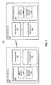
- FIG. 1illustrates sample aspects of a communication system 100 where a first wireless device 102 may be paired with a second wireless device 104.
- This pairingmay be performed in conjunction with, for example, an authentication procedure relating to establishing communication between the devices 102 and 104, a presence management operation that involves the devices 102 and 104, or some other operation that involves an interaction between the devices 102 and 104 where the interaction is predicated on a determination that the other device is trustworthy.
- FIG. 1 and the discussion that followsmay generally refer to a pairing process between two wireless devices. It should be appreciated, however, that the teachings herein may be adaptable to creating trust between more than two devices and that such devices need not be wireless.
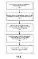
- FIG. 2Sample operations of the system 100 will be discussed in more detail in conjunction with the flowchart of FIG. 2 .
- the operations of FIG. 2may be described as being performed by specific components (e.g., system 100). It should be appreciated, however, that these operations may be performed by other types of components and may be performed using a different number of components. It also should be appreciated that one or more of the operations described herein may not be employed in a given implementation.
- a decisionmay be made to pair the devices 102 and 104.
- a usermay wish to use a wireless headset (e.g., device 104) with his or her cell phone (e.g., device 102).
- the devices 102 and 104may exchange one or more cryptographic keys that are then used to secure (e.g., encrypt) any messages sent between the devices 102 and 104.
- each device 102 and 104may wish to ensure that it is communicating with the intended device and not some other unauthorized device that may be attempting to compromise communication of either one or both of the devices 102 and 104. Accordingly, in accordance with some aspects of the disclosure a pairing process based on one or more synchronization tests may be employed to enable the devices 102 and 104 to verify whether they are indeed communicating with a trusted device.
- the pairing modemay be initiated through the use of user interfaces 106 and 108 of the devices 102 and 104, respectively.
- a usermay actuate input devices 110 and 112 of the user interfaces 106 and 108, respectively, to commence the pairing mode.
- the user interfaces 106 and 108may respectively include output devices 114 and 116 that provide one or more indications relating to the progress of the pairing mode operations.
- an appropriate indicationmay be generated by one or both of the output devices 114 and 116 to inform the user that he or she should simultaneously actuate the input devices 110 and 112.
- each device 102 and 104has a user input device (e.g., a button-type switch) and at least one of the devices 102 and 104 has a relatively simple user output device (e.g., a LED).
- a device 102e.g., a mobile phone
- the device 104may then simply employ a button or some other user input device 112 that the user may actuate in conjunction with the actuation of the keypad. In this case, an indication may be provided on the display screen to inform the user when to commence simultaneous actuation of the input devices 110 and 112.
- a user input devicemay comprise one or more of a variety of components that enable a user to provide some form of input to an associated device.
- the user input devicemay comprise one or more switches such as a pushbutton or a keypad.
- the user input devicealso may comprise a touch-screen, a touchpad, or other similar input mechanism.
- the user input devicemay comprise a pointing device such as a mouse, trackball, an electronic pen, a pointing stick, etc.
- the user input devicealso may be adapted to receive other forms of input such as an audio (e.g., voice) input, an optical-based input, an RF-based input, or some other suitable form of input.
- each of the devices 102 and 104provide one or more indications relating to the timing of one or more actuations of its respective input device.
- this indicationmay relate to the time at which an input device was actuated.
- this indicationmay relate to a set of time intervals defined by multiple actuations of an input device.
- each of the devicesmay transmit one or more indications relating to its actuation timing to the other device.
- a transceiver 118e.g., including transmitter and receiver components
- the device 102may transmit a message to a similar transceiver 120 of the device 104 to indicate that the input device 110 has been actuated.
- the indicationmay include information relating to the timing of that actuation (e.g., the time of actuation or a set of time intervals defined by multiple actuations).
- the indicationalso may comprise a commitment value (e.g., a hash code or a message authentication code) that is based on a set of time intervals generated at block 204.
- the device 104may thus receive one or more indications from the device 102 relating to the timing of one or more actuations for the device 102, and vice versa.
- the indication of block 206may simply comprise the time at which a message was received from the other device.
- authentication processors 122 and 124 on each devicemay then compare one or more indications relating to its actuation timing with one or more received indications that relate to the actuation timing of the other device. For example, as discussed below conjunction with FIG. 3 the authentication processor 124 may use the time of receipt of the message from the device 102 as an indication of the time of actuation of the input device 110. The authentication processor 124 may then compare that time of receipt with the time of actuation of its input device 112 to determine whether the actuations were sufficiently synchronized. Alternatively, as discussed below conjunction with FIG.
- the authentication processor 124may compare a received set of time intervals with its own set of time intervals and/or compare commitment (e.g., hash) values generated from these different sets of time intervals.
- the above comparison operationsmay employ one or more time duration threshold values that define maximum allowable deviations between the timings of the indications of the two devices.
- the authentication processor 122may perform similar comparison operations for its indication(s) and the indication(s) that it receives from the device 104.
- the devices 102 and 104may complete the pairing process.
- the authentication processor 122 of the device 102may authenticate the device 104
- the authentication processor 124 of the device 104may authenticate the device 102.
- the devices 102 and 104may exchange or otherwise cooperate to create one or more cryptographic keys to facilitate secure communications between the devices or to facilitate some other form of device interaction.
- the synchronization testmay be performed before the commencement of an authentication procedure (e.g., as a prerequisite to commencing an authentication procedure) or as part of an authentication procedure.
- a synchronization testmay serve as both a prerequisite to an authentication procedure and form a part of an authentication procedure.
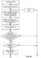
- the blocks on the left side of FIG. 3relate to operations that may be performed by a wireless device (e.g., device 102 of FIG. 1 ) that initiates the pairing mode while the blocks on the right side of FIG. 3 relate to operations that may be performed by another wireless device (e.g., the device 104 of FIG. 1 ) that responds to the initiation of the pairing mode.
- a wireless devicee.g., device 102 of FIG. 1
- another wireless devicee.g., the device 104 of FIG. 1
- the specific sequence of operations depicted in FIG. 3is for illustration purposes only, and that different circumstances may involve different sequences of operations.
- FIG. 3For illustration purposes, the operations of FIG. 3 will be discussed in the context of being performed by various components of a wireless device 400 as shown in FIG. 4 . It should be appreciated, however, that the illustrated components of the wireless device 400 are merely representative of components that may be employed here and that one or more of the operations of FIG. 3 may be performed by or in conjunction with other suitable components.
- both an initiator device and responder devicewill be discussed in conjunction with the single wireless device 400 depicted in FIG. 4 .
- the discussion belowwill refer to similar components it should be understood that the initiator device and the responder device will comprise separate devices 400.
- pairing modemay be initiated by a user using a user interface (e.g., interface 106 in FIG. 1 ) to invoke the corresponding functionality on the device (e.g., device 102).
- a user interfacee.g., interface 106 in FIG. 1
- an underlying protocolmay enable each device to: (1) find its peer; and (2) determine which device is the initiator and which is the responder.
- the designations of initiator and respondermay be determined in various ways.
- the responderis the device with a user interface (e.g., an LED).
- the devicesmay each generate a random number whereby the device that generates, for example, the larger number is selected as the initiator.
- the initiation of the pairing modemay be accomplished, for example, through the use of a pairing mode controller 402 that receives an input from an input device 404, causes an appropriate indication to be provided on an output device 406 (if applicable), and transmits an appropriate indication to another device via a transmitter 408 (if applicable).
- a pairing mode controller 402that receives an input from an input device 404, causes an appropriate indication to be provided on an output device 406 (if applicable), and transmits an appropriate indication to another device via a transmitter 408 (if applicable).
- at least one of the initiator and responder devicesmay inform the user that it is in pairing mode (e.g., LED blinking).
- pairing modemay simply be initiated by the user pressing the same user input devices (e.g., buttons) that are used for the synchronization operations.
- a wireless devicemay support other techniques (e.g., menu selection) to enable pairing mode.
- similar operationsmay be performed here by the responding devices.
- one of the devicesmay simply be set to pairing mode upon reception of an appropriate message from the other device.
- a receiver 410may receive the message from the other device and provide the associated information to the pairing mode controller 402 that invokes pairing mode operations on that device (e.g., device 104).
- the devices 102 and 104may be in pairing mode for a designated period of time (e.g., for T pair_enabled seconds). This time period may be defined large enough so that both devices may enter pairing mode without synchronization.
- the initiator device and/or the responder devicemay generate an indication to inform the user when to commence actuating the input devices of the initiator and responder devices.
- Such an indicationmay comprise, for example, a visual command on a display, a specific configuration of lighting elements (e.g., turning on or turning off LEDs), a vibration, or an audio command.
- the initiator devicewaits until its local input device (e.g., device 404) has been actuated. As mentioned above, in some implementations this may involve a user pressing a button of the initiator device at the same time he or she presses a button on the responder device.
- a timing indicator 412 and the transmitter 408 of the initiator devicecooperate to transmit a pair-request message to the responder device.
- the receiver 410 of the responder devicereceives this pair-request message as represented by block 310. As mentioned above, this time at which this message is received may serve as an indication as to the timing of the actuation at block 306.
- the responder devicewaits until its local input device (e.g., device 404) has been actuated.
- its local input devicee.g., device 404
- the detection operation of block 312may be made before or after the pair-request message is received at block 310, depending on the relative timings of the actuations of the devices and the processing time for each device to identify an actuation and to process the pair-request message.
- a comparator 414 of the responder devicecompares the timing of the actuation of block 312 with the timing of the receipt of the request message at block 310.
- the operationmay involve, for example, determining the difference between these two timings and comparing the resulting difference with a threshold.
- the comparator 414may compare the current time t with the recorded timing of a button-pressing event at block 312, denoted by T resp_button_pressing .
- the synchronization test of blocks 314 and 316may comprise determining whether:
- T maxdenotes the maximal allowable time interval between t and T resp_button_pressing when the two buttons are pressed by the same person.
- T maxmay be on the order of, for example, less than 0.1 seconds.
- the message transmission delaymay be ignored because it typically is much smaller than T max .
- the button sensing delaymay, in large part, be compensated at the other wireless device.
- the responder devicetransmits a pair-deny message at block 318 to the initiator device.
- the operations of both devicesmay then go back to the beginning of the pairing process. In this case, there may be no change in the user interface (e.g., LED still blinking).
- the pairing processmay continue.
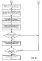
- the synchronization testinvolves multiple actuations by the user. For example, a subsequently detected actuation may involve the user releasing the buttons. Consequently, one or both of the devices may inform the user to keep holding the buttons (e.g., as indicated by maintaining the LED continuously ON). It should be appreciated here that similar functionality may be provided in other ways (e.g., by waiting for the local button to be pressed again).
- the responder devicethan waits for a defined period of time before performing the next operation (e.g., waiting for another actuation).
- the initiator devicewaits for the defined period of time after transmitting a message at block 308 before performing its next operation (e.g., waiting for another actuation).
- the defined period of timemay comprise a fixed time T FIXED plus a random time T RAND .
- the responder devicewaits until its local button is released.
- the responder devicemay inform the user to simultaneously release the two buttons (e.g., LED blinking).
- the responder devicetransmits a pair-acknowledgment message to the initiator device. Again, this operation may be performed by the cooperation of the timing indicator 412 and the transmitter 408 of the responder.
- the receiver 410 of the initiator devicereceives this pair-acknowledgement message as represented by block 328.
- the time at which this message is receivedmay thus serve as an indication as to the timing of the actuation at block 324.
- the initiator devicewaits until its local input device (e.g., device 404) has again been actuated. As mentioned above, in some implementations this may involve the user releasing a button or performing some other suitable act. In practice, the detection operation of block 330 may occur before or after the pair-request message is received at block 328.
- its local input devicee.g., device 404
- the comparator 414 of the initiator devicecompares the timing of the actuation of block 330 with the timing of the receipt of the acknowledgment message at block 328. Again, this operation may involve determining the difference between these two timings and comparing the resulting difference with a threshold. For example, the initiator device may compare the current time t with the recorded time of, for example, the local button releasing event, denoted by T init_button_releasing . The synchronization test at blocks 332 and 334 may thus involve determining whether:
- the initiator devicetransmits a pair-deny message to the responder device.
- the pairing processmay then be aborted.
- the cryptographic processor component 416may optionally perform a key agreement calculation at block 338. This operation may relate to, for example, providing one or more keys for use in subsequent operations of the initiator and responder devices.
- the initiator devicemay transmit a pair-confirm message to the responder device.
- this messagemay include authentication-related information (e.g., that is used to generate a key to be used for subsequent secure operations).
- this messageis not received at the responder device the current pairing operation is aborted as represented by block 342.
- the responding devicemay optionally perform its own key agreement calculation at block 344.
- the pair-request and pair-acknowledgement messagesmay have their own payloads. Consequently, a key to be used for securing subsequent operations may be generated from them.
- the key agreement schememay be a Diffie-Hellman algorithm or any entropy mixing scheme (e.g., SHA-256(payload1 ⁇ payload2)).
- the payloadmay comprise the sender's public key information and the confidentiality of the exchange key is protected.
- the pair-request messagemay include the initiator's public key and the pair-acknowledgement message may include the responder's public key.
- the initiator and responder devicesmay then successfully terminate the pairing mode.
- the responder devicemay inform the user of a successful pairing (e.g., the LED is continuously ON for a period of time, and is then turned OFF).
- An authenticator component 418 of each devicemay then perform any other operations that need to be performed in conjunction with authenticating these devices to one another.
- buttonsmay not be considered necessary, or multiple clicks of buttons may be used for additional assurance.
- a number of advantagesmay be provided through the use of the above pairing operations. For example, if a hacker wants to launch a man-in-the-middle attack, the hacker has to send pair-request or pair-confirm synchronized with the two target devices. Since the two target devices are being physically held by their real owner, it is highly unlikely that the hacker can figure out the right timing to send these messages. That is, one person can click the buttons within a time limit that is much smaller than the normal human reaction time. Consequently, by the time an observer sees a button being pressed and tries to press the button on their intruding device, it will be too late.
- a hackeralso may mount an attack that involves sending a large number of fake pair-request or pair-confirm messages continuously with the intent that one of them is received within the legal time interval.
- the receiver of the target devicemay only record the first valid message from the other end and may reject (e.g., ignore or discard) the repeated messages of the same type. By doing so, only the first of these fake messages will be recorded. In this case, however, it is unlikely that this fake message will be received within the legal time interval. For example, the fake message would likely be received before actuation of a receiving device's input device.
- FIG. 5another type of synchronization test that is based on time intervals between actuations will be treated in detail.
- the operations of FIG. 5will be discussed in the context of the wireless device 400. Again, it should be appreciated that the referenced components are merely representative and that the operations of FIG. 5 may be performed by or in conjunction with other suitable components.
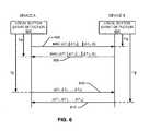
- FIG. 6illustrates sample timing relationships between messages that may be transmitted between a pair of wireless device (e.g., devices 102 and 104) in conjunction with, for example, the operations of FIG. 5 .
- these operationsinvolve detection of a local button event by each device (designated device A and device B in FIG. 6 ).
- the local button events at the devices A and Brelate to a series of actuations that define a set of time intervals (designated ⁇ T 1 - ⁇ T N and ⁇ T' 1 - ⁇ T' N , respectively).
- each deviceupon detection of the local button event, each device generates a message authentication code ("MAC") based on the corresponding set of time intervals and a cryptographic key K, and transmits the message authentication code to the other device as represented by the arrows 606 and 608.
- MACmessage authentication code
- Each of the devices A and Bthen waits for a defined period of time (T ⁇ and T' ⁇ , respectively) to receive a message from the other device. In the event the verification tests associated with these messages passes (as be discussed in more detail below in conjunction with FIG. 5 ), device A and device B wait for another defined period of time (T ⁇ and T' ⁇ , respectively), then transmit messages relating to their respective set of time intervals as represented by the arrows 610 and 612.
- FIG. 5simply depicts the operations of one of the wireless devices.
- the wireless devicescommence the pairing procedure. These operations may be similar to the pairing commencement operations discussed above in conjunction with blocks 302 and 304.
- the wireless devicesmay exchange key information or otherwise cooperate to enable each wireless device to obtain one or more keys to be used in conjunction with the pairing operation.
- the operations of block 504are performed before the commencement of the pairing procedure.
- the cryptographic processors 416 ( FIG. 4 ) of the devicesmay cooperate to generate a key K to be used to generate message authentication codes.
- the devicesdetermine the value K in a manner that ensures that no other device may establish an identical key with both of these devices.
- the two devicesmay use ephemeral Diffie-Hellman keys to derive the key K.
- each devicemay generate a Diffie-Hellman key pair when it boots up or each time before device authentication is required.
- elliptic curve Diffie-Hellmanmay be used for key exchange.
- the useragain physically holds the two devices (e.g., one in each hand).
- the userpicks several random timings to simultaneously press and/or release a button on each device.
- the timing indicator 412 of each wireless devicedetects the series of actuations at its respective input device (e.g., device 404) and defines a respective set of time intervals.
- the timing indicator 412 of each wireless devicedetects the series of actuations at its respective input device (e.g., device 404) and defines a respective set of time intervals.
- there are two sequences of timingsone recorded by device A: ( T 0 , T 1 , T 2 , ..., T N ), and another recorded by device B: ( T' 0 , T' 1 , T' 2 , ..., T' N ).
- Each time interval in a setthus indicates the amount of time that elapsed between unique pairs of successive actuations.
- the first time interval in a setmay correspond to the elapsed time between the first actuation and the second actuation.
- the second time interval in a setmay then correspond to the elapsed time between the second actuation and the third actuation.
- the two devicesmay not have synchronized clocks, the two sequences of time differences should contain very similar values since these button events are triggered by two fingers that are well synchronized by a human being. Consequently, their difference ( ⁇ T i - ⁇ T' i ) should be less than a threshold, ⁇ T th .
- a commitment generator 420(e.g., a hash or message authentication code generator) of each wireless device generates a commitment value (e.g., hash code or message authentication code) or performs some other suitable operation based that device's set of time intervals.
- a commitment valuee.g., hash code or message authentication code
- the wireless device Agenerates a message authentication code based on ( ⁇ T 1 ⁇ T 2 ⁇ ... ⁇ ⁇ T N ) and K while the wireless device B generates a message authentication code based on ( ⁇ T' 1 ⁇ ⁇ T' 2 ⁇ ... ⁇ ⁇ T' N ) and K .
- ⁇denotes concatenation, and all time differences may be expressed as bit strings.
- time interval datamay be manipulated in other ways (e.g., summed).
- commitment generator 420may implement other types of keyed hash algorithms including, for example, HMAC or may implement a block cipher in CBC-MAC or CMAC mode.
- a commitment schememay involve generating a commitment based on a "secret” such as the time intervals and, optionally, other data to be authenticated and providing the commitment to another device.
- the other deviceperforms complementary operations.
- a given devicemay not use the other device's "secret” to generate its commitment.
- a subsequent verification operationinvolves sending the "secret” (e.g., the time intervals) to the other device. In this way, each device may use the "secret” and the commitment it received to authenticate the other device.
- the operations of block 508relate to performing a cryptographic operation on the data to be transmitted. Consequently, similar functionality may be provided through the use of other cryptographic techniques such as a digital signature.
- the commitment generator 420may comprise a digital signature generator.
- each wireless devicetransmits its commitment (e.g., message authentication code) to the other wireless device.
- this messagecomprises an indication relating to the timing of the actuations of block 506.
- This transmissionmay be asynchronous with respect to the other wireless device. That is, the time at which one wireless device transmits its message authentication code may not be based on the time at which the other wireless device transmits its message authentication code.
- each devicewaits to receive a commitment (e.g., message authentication code) from the other device.
- a commitmente.g., message authentication code
- the processmay be aborted as represented by block 514 (e.g., and the process is restarted from button event detection).
- the operations of block 512involve the comparator 414 determining the time difference between a time relating to the actuation times (e.g., the last local button event time T N or T' N ) and the time of receipt of the incoming message authentication code at block 512. In some aspects, this difference value must be less than a predefined threshold ⁇ T ⁇ .
- the incoming message authentication code for device Amay thus be deemed valid if: ( T ⁇ - T N ) ⁇ ⁇ T ⁇ -max .
- the incoming message authentication code for device Bmay be deemed valid if: ( T' ⁇ - T' N ) ⁇ ⁇ T ⁇ -max .
- the processmay be aborted in the event the two devices send identical commitments (e.g., message authentication codes) to each other.
- the pairing schemeprevents another device from simply transmitting back, for example, a message authentication code that it received from either device A or device B (e.g., in an attempted "replay attack").
- each deviceremains idle until more than a defined period of time (e.g., ⁇ T ⁇ -min ) elapses after a designated time relating to the corresponding actuation times (e.g., the last local button event T N or T' N ).
- ⁇ T ⁇ -minmay be defined to be less than or equal to ⁇ T ⁇ -max .
- timing constraints as described abovemay prevent a man-in-the-middle attack where the attacker fails in authentication with one target but obtains the genuine sequence of time differences. In such a case, the attacker could try to use this sequence to authenticate to the other target.
- the man-in-the-middlewill not pass the timing check for T ⁇ and T ⁇ because it is too late to send the correct message authentication code. That is, under the scheme set forth above a device will not transmit its set of time intervals (line 610 or 612 in FIG. 6 ) until it receives a commitment such as the message authentication code (line 606 or 608 in FIG. 6 ) from the other device.
- each wireless devicetransmits its set of time intervals to the other side for verification. As represented by block 522, each wireless device thereby receives the corresponding set of time intervals from the other device. This message thus comprises an indication relating to the timing of the actuations of block 506.
- the comparator 414calculates the difference between corresponding time intervals of each set of time intervals. For example, the comparator 414 determines the difference in time between the first time interval in the set of intervals generated at device A and the first time interval in the set of intervals generated at device B. A similar time difference may then be calculated for each time interval in each set.
- the comparator 414generates a verification count based on these time differences.
- the defined value mis the minimum number of successful tests that is deemed acceptable to pass the verification process ( m ⁇ n ). In other words, this test determines whether an acceptable number of the time differences are within the range defined by ⁇ T th .
- the pairing processmay be aborted.
- the wireless devicemay verify that a commitment (e.g., message authentication code) generated from the set of time intervals received at block 522 matches the commitment (e.g., message authentication code) received at block 512.
- a commitmente.g., message authentication code
- the message authentication code generator 420may generate a message authentication code based on the set of time intervals received at block 522 and the key K .
- the comparator 414may then compare this message authentication code with the message authentication code received from the other wireless device at block 512. Exchanging the message authentication code at the beginning of the protocol (e.g., at blocks 510 - 512) may thereby prevent either side from cheating. For example, once the message authentication code is transmitted, it may be infeasible to find another input message (e.g., sequence of time differences) with the same message authentication code.
- the pairing processmay be aborted. Otherwise, the other wireless device may be deemed successfully authenticated (block 534).
- the techniques taught hereinmay be employed to prevent a malicious device from capturing finger movement timings through eavesdropping and analysis of wireless traffic during device pairing.
- an implementation based on the teachings hereinmay not require complicated protocol or high cost device provisioning.
- Kis authenticated at block 534 as well.
- Kmay have been initially exchanged between devices that did not trust one another.
- Kis authenticated by the above distance-based authentication whereby trust derives from the same person operating the devices.
- Kmay be used for subsequent cryptographic operations (e.g., encryption, authentication, and so on).
- a commitment operationmay be implemented in a variety of ways. For example, cryptographic operations other than MAC-based operations may be employed here. In addition, any of the operations taught herein may be used to associate additional data for authentication. Also, a pre-shared secret key K may not be required.
- the commitment valuecan be the hash of (time intervals ⁇ Diffie-Hellman public key ⁇ device identifier) so that the Diffie-Hellman public key and the identifier of the other device are authenticated at block 534.
- the commitmentmay be based on any type of data that needs to be authenticated.
- the above MAC operationmay be based on other data in addition to or other than one or more of the pre-shared key K , the public key, and the device ID discussed above.
- a commitment schememay employ encryption and decryption operations.
- the commitment schememay involve using a key to encrypt a secret (e.g., time interval information).
- the resulting cipher textis transmitted to another device.
- the keyis transmitted to the other device.
- Each devicemay then use the key it receives to decrypt the received cipher text to thereby obtain the "secret” of the other device. This restored "secret” may then be compared with the received "secret” (e.g., the time intervals) to authenticate the other device.
- a commitmentmay be based on information that is provided to prevent a replay attack.
- a first devicemay generate a MAC based on the time intervals and some type of information (referred to as a device identifier in the following discussion) that distinguishes the first device (e.g., an initiator) from a second device (e.g., a responder).
- the first devicetransmits the MAC to the second device that is expected to perform a complementary operation.
- each deviceAfter receiving a MAC from the other device, each device transmits its device identifier (e.g., "0" for the first device and "1" for the second device) in the clear.
- the device identifiermay be transmitted in the plain text of the MAC message (e.g., at block 510 in FIG. 5 ) or along with the time interval information.
- the second devicemay transmit the device identifier of the first device (e.g., "0") in the clear.
- the first devicemay readily determine that this is a replay upon checking the device identifier. Referring to FIG. 5 , the operation of block 516 (or some other block) may thus be replaced (or augmented) with checking the received device identifier to make sure that it is different than the device identifier of the device performing the check (e.g., the first device above).
- FIG. 7depicts several sample components that may be employed to facilitate communication between devices.
- a first device 702 and a second device 704are adapted to communicate via a wireless communication link 706 over a suitable medium.
- a transmit (“TX”) data processor 708receives traffic data (e.g., data packets) from a data buffer 710 or some other suitable component.
- the transmit data processor 708processes (e.g., encodes, interleaves, and symbol maps) each data packet based on a selected coding and modulation scheme, and provides data symbols.
- a data symbolis a modulation symbol for data
- a pilot symbolis a modulation symbol for a pilot (which is known a priori).
- a modulator 712receives the data symbols, pilot symbols, and possibly signaling for the reverse link, and performs modulation (e.g., OFDM or some other suitable modulation) and/or other processing as specified by the system, and provides a stream of output chips.
- a transmitter (“TMTR") 714processes (e.g., converts to analog, filters, amplifies, and frequency upconverts) the output chip stream and generates a modulated signal, which is then transmitted from an antenna 716.
- the modulated signals transmitted by the device 702are received by an antenna 718 of the device 704.
- a receiver (“RCVR”) 720processes (e.g., conditions and digitizes) the received signal from the antenna 718 and provides received samples.
- a demodulator (“DEMOD”) 722processes (e.g., demodulates and detects) the received samples and provides detected data symbols, which may be a noisy estimate of the data symbols transmitted to the device 704 by the other device(s).
- a receive (“RX”) data processor 724processes (e.g., symbol demaps, deinterleaves, and decodes) the detected data symbols and provides decoded data associated with each transmitting device (e.g., device 702).
- Traffic datais processed by a transmit (“TX") data processor 726 to generate data symbols.
- a modulator 728receives the data symbols, pilot symbols, and signaling for the forward link, performs modulation (e.g., OFDM or some other suitable modulation) and/or other pertinent processing, and provides an output chip stream, which is further conditioned by a transmitter (“TMTR") 730 and transmitted from the antenna 718.
- signaling for the forward linkmay include power control commands and other information (e.g., relating to a communication channel) generated by a controller 732 for all devices (e.g. terminals) transmitting on the reverse link to the device 704.
- the modulated signal transmitted by the device 704is received by the antenna 716, conditioned and digitized by a receiver (“RCVR”) 734, and processed by a demodulator (“DEMOD”) 736 to obtain detected data symbols.
- a receive (“RX”) data processor 738processes the detected data symbols and provides decoded data for the device 702 and the forward link signaling.
- a controller 740receives power control commands and other information to control data transmission and to control transmit power on the reverse link to the device 704.
- the controllers 740 and 732direct various operations of the device 702 and the device 704, respectively. For example, a controller may determine an appropriate filter, reporting information about the filter, and decode information using a filter.
- Data memories 742 and 744may store program codes and data used by the controllers 740 and 732, respectively.
- FIG. 7also illustrates that the communication components may include one or more components that perform operations relating to synchronization tests as taught herein.
- a synchronization (“SYNC.") control componentmay cooperate with the controller 740 and/or other components of the device 702 to send/receive synchronization-related information to/from another device (e.g., device 704).
- a synchronization control component 748may cooperate with the controller 732 and/or other components of the device 704 to send/receive synchronization-related information to/from another device (e.g., device 702).
- a wireless devicemay include various components that perform functions based on signals that are transmitted by or received at the wireless device.
- a wireless headsetmay include a transducer adapted to provide an audio output based on a signal received via the receiver.
- a wireless watchmay include a user interface adapted to provide an indication based on a signal received via the receiver.
- a wireless sensing devicemay include a sensor adapted to provide data to be transmitted to another device.
- a wireless devicemay communicate via one or more wireless communication links that are based on or otherwise support any suitable wireless communication technology.
- a wireless devicemay associate with a network.
- the networkmay comprise a body area network or a personal area network (e.g., an ultra-wideband network).
- the networkmay comprise a local area network or a wide area network.
- a wireless devicemay support or otherwise use one or more of a variety of wireless communication technologies, protocols, or standards such as, for example, CDMA, TDMA, OFDM, OFDMA, WiMAX, and Wi-Fi.
- a wireless devicemay support or otherwise use one or more of a variety of corresponding modulation or multiplexing schemes.
- a wireless devicemay thus include appropriate components (e.g., air interfaces) to establish and communicate via one or more wireless communication links using the above or other wireless communication technologies.
- a devicemay comprise a wireless transceiver with associated transmitter and receiver components (e.g., transmitter 408 and receiver 410) that may include various components (e.g., signal generators and signal processors) that facilitate communication over a wireless medium.
- a wireless devicemay communicate via an impulse-based wireless communication link.
- an impulse-based wireless communication linkmay utilize ultra-wideband pulses that have a relatively short length (e.g., on the order of a few nanoseconds) and a relatively wide bandwidth.
- the ultra-wideband pulsesmay have a fractional bandwidth on the order of approximately 20% or more and/or have a bandwidth on the order of approximately 500 MHz or more.
- teachings hereinmay be incorporated into (e.g., implemented within or performed by) a variety of apparatuses (e.g., devices).
- a phonee.g., a cellular phone
- PDApersonal data assistant
- an entertainment devicee.g., a music or video device
- a headsete.g., headphones, an earpiece, etc.
- a microphonee.g., a medical device (e.g., a biometric sensor, a heart rate monitor, a pedometer, an EKG device, etc.), a user I/O device (e.g., a watch, a remote control, a light switch, a keyboard, a mouse, etc.), a tire pressure monitor, a computer, a point-of-sale device, an entertainment device, a hearing aid, a set-top box, or any other suitable device.
- a medical devicee.g., a biometric sensor, a heart rate monitor, a pedometer,
- teachings hereinmay be adapted for use in low power applications (e.g., through the use of an impulse-based signaling scheme and low duty cycle modes) and may support a variety of data rates including relatively high data rates (e.g., through the use of high-bandwidth pulses).
- a wireless devicemay comprise an access device (e.g., a Wi-Fi access point) for a communication system.
- an access devicemay provide, for example, connectivity to another network (e.g., a wide area network such as the Internet or a cellular network) via a wired or wireless communication link.
- the access devicemay enable another device (e.g., a Wi-Fi station) to access the other network or some other functionality.
- another devicee.g., a Wi-Fi station
- one or both of the devicesmay be portable or, in some cases, relatively non-portable.
- an apparatus 800is represented as a series of interrelated functional blocks that may represent functions implemented by, for example, one or more integrated circuits (e.g., an ASIC) or may be implemented in some other manner as taught herein.
- an integrated circuitmay include a processor, software, other components, or some combination thereof.
- the apparatus 800may include one or more modules that may perform one or more of the functions described above with regard to various figures.
- an ASIC for transmitting 802may correspond to, for example, a transmitter as discussed herein.
- An ASIC for receiving 804may correspond to, for example, a receiver as discussed herein.
- An ASIC for inputting 806may correspond to, for example, an input device as discussed herein.
- An ASIC for providing time of actuation indication 808may correspond to, for example, a timing indicator as discussed herein.
- An ASIC for comparing 810may correspond to, for example, a comparator as discussed herein.
- An ASIC for calculating key agreement 812may correspond to, for example, a cryptographic processor as discussed herein.
- An ASIC for generating a commitment (hash, MAC) 814may correspond to, for example, a commitment (e.g., hash/MAC) generator as discussed herein.
- An ASIC for activating pairing mode 816may correspond to, for example, a pairing mode controller as discussed herein.
- An ASIC for generating indication 818may correspond to, for example, an output device as discussed herein.
- An ASIC for authenticating 820may correspond to, for example, an authenticator as discussed herein.
- these componentsmay be implemented via appropriate processor components. These processor components may in some aspects be implemented, at least in part, using structure as taught herein. In some aspects a processor may be adapted to implement a portion or all of the functionality of one or more of these components. In some aspects one or more of the components represented by dashed boxes are optional.
- the apparatus 800may comprise one or more integrated circuits.
- a single integrated circuitmay implement the functionality of one or more of the illustrated components, while in other aspects more than one integrated circuit may implement the functionality of one or more of the illustrated components.
- FIG. 8may be implemented using any suitable means. Such means also may be implemented, at least in part, using corresponding structure as taught herein.
- the components described above in conjunction with the "ASIC for" components of FIG. 8also may correspond to similarly designated “means for” functionality.
- one or more of such meansmay be implemented using one or more of processor components, integrated circuits, or other suitable structure as taught herein.
- any reference to an element herein using a designation such as “first,” “second,” and so forthdoes not generally limit the quantity or order of those elements. Rather, these designations are used herein as a convenient method of distinguishing between two or more different devices, sets, etc. Thus, a reference to first and second devices or sets does not mean that only two devices or sets may be employed there or that the first device or set must precede the second device or set in some manner.
- any of the various illustrative logical blocks, modules, processors, means, circuits, and algorithm steps described in connection with the aspects disclosed hereinmay be implemented as electronic hardware (e.g., a digital implementation, an analog implementation, or a combination of the two, which may be designed using source coding or some other technique), various forms of program or design code incorporating instructions (which may be referred to herein, for convenience, as "software” or a "software module”), or combinations of both.
- softwareor a “software module”
- various illustrative components, blocks, modules, circuits, and stepshave been described above generally in terms of their functionality. Whether such functionality is implemented as hardware or software depends upon the particular application and design constraints imposed on the overall system. Skilled artisans may implement the described functionality in varying ways for each particular application, but such implementation decisions should not be interpreted as causing a departure from the scope of the present disclosure.
- the various illustrative logical blocks, modules, and circuits described in connection with the aspects disclosed hereinmay be implemented within or performed by an integrated circuit ("IC"), an access terminal, or an access point.
- the ICmay comprise a general purpose processor, a digital signal processor (DSP), an application specific integrated circuit (ASIC), a field programmable gate array (FPGA) or other programmable logic device, discrete gate or transistor logic, discrete hardware components, electrical components, optical components, mechanical components, or any combination thereof designed to perform the functions described herein, and may execute codes or instructions that reside within the IC, outside of the IC, or both.
- a general purpose processormay be a microprocessor, but in the alternative, the processor may be any conventional processor, controller, microcontroller, or state machine.
- a processormay also be implemented as a combination of computing devices, e.g., a combination of a DSP and a microprocessor, a plurality of microprocessors, one or more microprocessors in conjunction with a DSP core, or any other such configuration.
- a software modulee.g., including executable instructions and related data
- other datamay reside in a data memory such as RAM memory, flash memory, ROM memory, EPROM memory, EEPROM memory, registers, a hard disk, a removable disk, a CD-ROM, or any other form of computer-readable storage medium known in the art.
- a sample storage mediummay be coupled to a machine such as, for example, a computer/processor (which may be referred to herein, for convenience, as a "processor") such the processor can read information (e.g., code) from and write information to the storage medium.
- a sample storage mediummay be integral to the processor.
- the processor and the storage mediummay reside in an ASIC.
- the ASICmay reside in user equipment.
- the processor and the storage mediummay reside as discrete components in user equipment.
- any suitable computer-program productmay comprise a computer-readable medium comprising codes (e.g., executable by at least one computer) relating to one or more of the aspects of the disclosure.
- a computer program productmay comprise packaging materials.
Landscapes
- Engineering & Computer Science (AREA)
- Computer Security & Cryptography (AREA)
- Computer Networks & Wireless Communication (AREA)
- Theoretical Computer Science (AREA)
- Signal Processing (AREA)
- Computer Hardware Design (AREA)
- General Engineering & Computer Science (AREA)
- Software Systems (AREA)
- General Physics & Mathematics (AREA)
- Physics & Mathematics (AREA)
- Computing Systems (AREA)
- Mobile Radio Communication Systems (AREA)
- Telephone Function (AREA)
- Near-Field Transmission Systems (AREA)
- Collating Specific Patterns (AREA)
- Measurement Of The Respiration, Hearing Ability, Form, And Blood Characteristics Of Living Organisms (AREA)
- Lock And Its Accessories (AREA)
Description
- This application claims the benefit of and priority to commonly owned
U.S. Provisional Patent Application No. 60/908,271, filed March 27, 2007 - This application relates generally to wireless communication and more specifically, but not exclusively, to synchronization tests for device authentication.
- Wireless devices may employ a pairing process in an attempt to form a level of trust with one another in conjunction with authenticating with each other or exchanging cryptographic keys that may be used for services that are protected by cryptographic techniques. For example, in Bluetooth, authentication between two devices may involve the exchange of a passcode between the devices. In some implementations such a procedure may involve the use of a sophisticated user interface for passcode input. Conversely, in implementations that employ relatively simple user interface devices for passcode input, the associated provisioning cost may be relatively high. Moreover, a typical passcode used by users may be four to eight digits long, which may not be strong enough to prevent the security of the devices from being compromised by conventional cryptanalysis.
- Bluetooth V2.1 proposes using elliptic curve Diffie-Hellman for key exchange. Here, based on a secret derived from elliptic curve Diffie-Hellman, device authentication may be based on numeric comparison or passkey entry. However, these methods may utilize a sophisticated user interface and may be relatively susceptible to man-in-the-middle attacks.
- Near field communication technology also may be used for device authentication. For example, near field communication devices may be designed to perform a handshake only when they are brought within a defined "touching" distance of each other. It may be possible, however, to design a near field communication device with a custom antenna that extends the working distance for the handshake. In this case, an unauthorized person or device may be able to authenticate with another device from relatively long range thereby thwarting the security otherwise provided the requirement of relatively close proximity of the devices. Consequently, authentication that is based on a relatively small touching distance as provided by near field communication may not provide a sufficient level of security.
US 2003/005085 andUS 2005/132234 is further background art.- The invention is defined by the appended claims.
- A summary of sample aspects of the disclosure follows. It should be understood that any reference to aspects herein may refer to one or more aspects of the disclosure.
- The disclosure relates in some aspects authenticating devices or performing other similar operations based on the ability of a human to synchronize the movements of his or her fingers. For example, a person may be able to press or release two buttons in a simultaneous manner or in a substantially simultaneous manner. In contrast, it may be relatively difficult for an onlooker to anticipate and synchronize to the timings of the finger movements of the other person. Consequently, a pairing procedure for two wireless devices may involve a synchronization test that is based on the relative timing of actuations of input devices on each of the wireless devices. Here, it is unlikely that an onlooker would be able to press or release a button on his or her own wireless device in an attempt to interfere with the pairing of the wireless devices by the other person.
- In some aspects, for purposes of device authentication, presence management, or other operations a pair of wireless devices may be deemed trustable with respect to one another if the same person is physically holding the two wireless devices. Consequently, when two wireless devices being held by the same person communicate with each other, a message sent by a first one of the wireless devices relating to a local synchronization event (e.g., actuation of a user input device) at the first device may be deemed trustable by a second one of the wireless devices that receives the message. To ensure that the same person is holding the devices, the receiving device verifies that the timing of the received message is substantially synchronized with a similar local synchronization event at the second device. Consequently, an authentication or other similar procedure may involve determining whether an input device on a first device is actuated (e.g., depressed and/or released) at substantially the same time or times that an input device on a second device is actuated.
- The disclosure relates in some aspects to a synchronization test that involves determining whether actuations of user input devices on two different wireless devices occurred within a defined time interval with respect to one another. Here, a user may be instructed to simultaneously actuate a user input device on each wireless device. A first one of the wireless devices may determine the actuation time associated with a second one of the wireless devices based on the time at which the first device receives a message from the second device relating to the actuation of the second device. The first device may thus compare the actuation time of its user input device with the time it received the message from the second device. The second device may perform a similar synchronization test. In the event the synchronization tests pass on both devices, the devices may authenticate one another. In some aspects a cryptographic key agreement scheme may be employed in conjunction with the synchronization tests. In addition, in some aspects the synchronization tests may be based on the timings of more than one actuation of each user input device.
- The disclosure relates in some aspects to a synchronization test that involves comparing time intervals between multiple actuations of user input devices on two different wireless devices. Here, a user may be instructed to simultaneously actuate a user input device on each wireless device in a repeated (e.g., random) manner. That is, the user may repeatedly actuate each user input device at the same time. In this way a set of time intervals corresponding to the times between actuations will be defined on each wireless device. Each of the devices may then send a commitment value (e.g., a hash code or a message authentication code) that is based on its set of time intervals to the other device. The description that follows describes the use of a hash value, a message authentication code or other schemes to illustrate sample ways to implement a commitment scheme. It should be appreciated that other cryptographic techniques may be used to generate a commitment value in accordance with the teachings herein. As one step of the verification process, each of the devices may compare an actuation time of its user input device with the time it received the commitment (e.g., hash) message from the other device. Assuming this step of the verification process passes, after a delay period the devices may each send its set of time intervals to the other device. In this way, in another step of the verification process the devices may determine whether corresponding pairs of time intervals from each of the two sets of time intervals are sufficiently similar. In addition, in yet another step of the verification process, the devices may generate a commitment (e.g., hash) value based on the set of time intervals it received from the other device and compare that commitment value with the commitment value it previously received from the other device to verify that both received messages relate to the same set of time intervals. In the event the synchronization tests pass on both devices, the devices may authenticate one another.
- These and other aspects of the disclosure will be more fully understood when considered with respect to the following detailed description, appended claims, and accompanying drawings, wherein:
FIG. 1 is a simplified block diagram of several sample aspects of a communication system comprising wireless devices;FIG. 2 is a flowchart of several sample aspects of operations that may be performed to authenticate two or more devices;FIG. 3 , includingFIGS. 3A and3B , is a flowchart of several sample aspects of operations that may be performed to pair two wireless devices based on the time difference between an actuation of a user input device of each wireless device;FIG. 4 is a simplified block diagram of several sample aspects of a wireless device;FIG. 5 , includingFIGS. 5A and5B , is a flowchart of several sample aspects of operations that may be performed to pair two wireless devices based on differences between time durations defined by a series of actuations of a user input device of each wireless device;FIG. 6 is a simplified diagram of sample timing relating to the operations ofFIG. 5 ;FIG. 7 is a simplified block diagram of several sample aspects of communication components; andFIG. 8 is a simplified block diagram of several sample aspects of an apparatus configured to support a synchronization test.- The various features illustrated in the drawings may not be drawn to scale and may be simplified for clarity. Consequently, the drawings may not depict every aspect of a particular apparatus (e.g., device) or method. In addition, similar reference numerals may be used to denote similar features herein.
- Various aspects of the disclosure are described below. It should be apparent that the teachings herein may be embodied in a wide variety of forms and that any specific structure, function, or both being disclosed herein is merely representative. Based on the teachings herein one skilled in the art should appreciate that an aspect disclosed herein may be implemented independently of any other aspects and that two or more of these aspects may be combined in various ways. For example, an apparatus may be implemented or a method may be practiced using any number of the aspects set forth herein. In addition, such an apparatus may be implemented or such a method may be practiced using other structure, functionality, or structure and functionality in addition to or other than one or more of the aspects set forth herein. As an example of the above, as discussed below first and second actuation timing-related indications may be compared to determine whether at least one time of actuation of a first user input device is sufficiently similar to at least one time of actuation of a second user input device. In some aspects each of the at least one time of actuation of the first and second user input devices relates to a single time of actuation of each input device. In contrast, in some aspects each of the at least one time of actuation of the first and second user input devices relates to a set of time intervals defined by a series of actuations of each of the input devices.
FIG. 1 illustrates sample aspects of acommunication system 100 where afirst wireless device 102 may be paired with asecond wireless device 104. This pairing may be performed in conjunction with, for example, an authentication procedure relating to establishing communication between thedevices devices devices FIG. 1 and the discussion that follows may generally refer to a pairing process between two wireless devices. It should be appreciated, however, that the teachings herein may be adaptable to creating trust between more than two devices and that such devices need not be wireless.- Sample operations of the
system 100 will be discussed in more detail in conjunction with the flowchart ofFIG. 2 . For convenience, the operations ofFIG. 2 (or any other operations discussed or taught herein) may be described as being performed by specific components (e.g., system 100). It should be appreciated, however, that these operations may be performed by other types of components and may be performed using a different number of components. It also should be appreciated that one or more of the operations described herein may not be employed in a given implementation. - As represented by
block 202 ofFIG. 2 , at some point in time a decision may be made to pair thedevices devices devices device devices devices - In some aspects the pairing mode may be initiated through the use of
user interfaces devices input devices user interfaces user interfaces output devices devices output devices input devices - The
user interfaces device devices user input device 110 and theuser output device 114, respectively. Thedevice 104 may then simply employ a button or some otheruser input device 112 that the user may actuate in conjunction with the actuation of the keypad. In this case, an indication may be provided on the display screen to inform the user when to commence simultaneous actuation of theinput devices - In general, a user input device may comprise one or more of a variety of components that enable a user to provide some form of input to an associated device. For example, the user input device may comprise one or more switches such as a pushbutton or a keypad. The user input device also may comprise a touch-screen, a touchpad, or other similar input mechanism. The user input device may comprise a pointing device such as a mouse, trackball, an electronic pen, a pointing stick, etc. The user input device also may be adapted to receive other forms of input such as an audio (e.g., voice) input, an optical-based input, an RF-based input, or some other suitable form of input.
- As represented by
block 204 ofFIG. 2 , each of thedevices FIG. 3 , this indication may relate to the time at which an input device was actuated. Alternatively, as will be discussed in conjunction withFIG. 5 , this indication may relate to a set of time intervals defined by multiple actuations of an input device. - To enable each device to compare its actuation timing with the actuation timing of the other device, each of the devices may transmit one or more indications relating to its actuation timing to the other device. For example, upon actuation of the input device 110 a transceiver 118 (e.g., including transmitter and receiver components) of the
device 102 may transmit a message to asimilar transceiver 120 of thedevice 104 to indicate that theinput device 110 has been actuated. In addition, the indication may include information relating to the timing of that actuation (e.g., the time of actuation or a set of time intervals defined by multiple actuations). As discussed below conjunction withFIG. 5 , the indication also may comprise a commitment value (e.g., a hash code or a message authentication code) that is based on a set of time intervals generated atblock 204. - As represented by
block 206, the device 104 (e.g., the transceiver 120) may thus receive one or more indications from thedevice 102 relating to the timing of one or more actuations for thedevice 102, and vice versa. As mentioned above, in some implementations the indication ofblock 206 may simply comprise the time at which a message was received from the other device. - As represented by
block 208,authentication processors FIG. 3 theauthentication processor 124 may use the time of receipt of the message from thedevice 102 as an indication of the time of actuation of theinput device 110. Theauthentication processor 124 may then compare that time of receipt with the time of actuation of itsinput device 112 to determine whether the actuations were sufficiently synchronized. Alternatively, as discussed below conjunction withFIG. 5 theauthentication processor 124 may compare a received set of time intervals with its own set of time intervals and/or compare commitment (e.g., hash) values generated from these different sets of time intervals. In some implementations the above comparison operations may employ one or more time duration threshold values that define maximum allowable deviations between the timings of the indications of the two devices. Concurrently with the above operations, theauthentication processor 122 may perform similar comparison operations for its indication(s) and the indication(s) that it receives from thedevice 104. - As represented by
block 210, if the results above the above synchronization tests indicate that there is a sufficient probability that theinput devices devices authentication processor 122 of thedevice 102 may authenticate thedevice 104, and theauthentication processor 124 of thedevice 104 may authenticate thedevice 102. In conjunction with this operation or at some other point in time, thedevices - In some implementations the synchronization test may be performed before the commencement of an authentication procedure (e.g., as a prerequisite to commencing an authentication procedure) or as part of an authentication procedure. In addition, in some implementations a synchronization test may serve as both a prerequisite to an authentication procedure and form a part of an authentication procedure.
- With the above overview in mind, additional details relating to one type of synchronization test will be discussed in conjunction with the flowchart of
FIG. 3 . In general, the blocks on the left side ofFIG. 3 relate to operations that may be performed by a wireless device (e.g.,device 102 ofFIG. 1 ) that initiates the pairing mode while the blocks on the right side ofFIG. 3 relate to operations that may be performed by another wireless device (e.g., thedevice 104 ofFIG. 1 ) that responds to the initiation of the pairing mode. Here, it should be appreciated that the specific sequence of operations depicted inFIG. 3 is for illustration purposes only, and that different circumstances may involve different sequences of operations. - For illustration purposes, the operations of
FIG. 3 will be discussed in the context of being performed by various components of awireless device 400 as shown inFIG. 4 . It should be appreciated, however, that the illustrated components of thewireless device 400 are merely representative of components that may be employed here and that one or more of the operations ofFIG. 3 may be performed by or in conjunction with other suitable components. - In addition, for convenience the operations of both an initiator device and responder device will be discussed in conjunction with the
single wireless device 400 depicted inFIG. 4 . Thus, while the discussion below will refer to similar components it should be understood that the initiator device and the responder device will compriseseparate devices 400. - At
blocks interface 106 inFIG. 1 ) to invoke the corresponding functionality on the device (e.g., device 102). Here, an underlying protocol may enable each device to: (1) find its peer; and (2) determine which device is the initiator and which is the responder. The designations of initiator and responder may be determined in various ways. For example, in some implementations the responder is the device with a user interface (e.g., an LED). In some implementations the devices may each generate a random number whereby the device that generates, for example, the larger number is selected as the initiator. - In
FIG. 4 the initiation of the pairing mode may be accomplished, for example, through the use of apairing mode controller 402 that receives an input from aninput device 404, causes an appropriate indication to be provided on an output device 406 (if applicable), and transmits an appropriate indication to another device via a transmitter 408 (if applicable). For example, at least one of the initiator and responder devices may inform the user that it is in pairing mode (e.g., LED blinking). In some implementations pairing mode may simply be initiated by the user pressing the same user input devices (e.g., buttons) that are used for the synchronization operations. In other implementations a wireless device may support other techniques (e.g., menu selection) to enable pairing mode. - In some implementations similar operations may be performed here by the responding devices. Alternatively, one of the devices may simply be set to pairing mode upon reception of an appropriate message from the other device. In this case, a
receiver 410 may receive the message from the other device and provide the associated information to thepairing mode controller 402 that invokes pairing mode operations on that device (e.g., device 104). - The
devices - In some implementations the initiator device and/or the responder device may generate an indication to inform the user when to commence actuating the input devices of the initiator and responder devices. Such an indication may comprise, for example, a visual command on a display, a specific configuration of lighting elements (e.g., turning on or turning off LEDs), a vibration, or an audio command.
- At
block 306 the initiator device waits until its local input device (e.g., device 404) has been actuated. As mentioned above, in some implementations this may involve a user pressing a button of the initiator device at the same time he or she presses a button on the responder device. Once the initiator device detect the local actuation event, at block 308 atiming indicator 412 and thetransmitter 408 of the initiator device cooperate to transmit a pair-request message to the responder device. Thereceiver 410 of the responder device receives this pair-request message as represented byblock 310. As mentioned above, this time at which this message is received may serve as an indication as to the timing of the actuation atblock 306. - Similar to the initiator device operation of
block 306, atblock 312 the responder device waits until its local input device (e.g., device 404) has been actuated. In practice, the detection operation ofblock 312 may be made before or after the pair-request message is received atblock 310, depending on the relative timings of the actuations of the devices and the processing time for each device to identify an actuation and to process the pair-request message. - At block 314 a
comparator 414 of the responder device compares the timing of the actuation ofblock 312 with the timing of the receipt of the request message atblock 310. The operation may involve, for example, determining the difference between these two timings and comparing the resulting difference with a threshold. - For example, assuming the button was pressed (block 312) before the pair-request message was received, upon receipt of the pair-request message the
comparator 414 may compare the current timet with the recorded timing of a button-pressing event atblock 312, denoted byTresp_button_pressing. Thus, the synchronization test ofblocks - Here,Tmax denotes the maximal allowable time interval between t andTresp_button_pressing when the two buttons are pressed by the same person. In some implementationsTmax may be on the order of, for example, less than 0.1 seconds. Here, the message transmission delay may be ignored because it typically is much smaller thanTmax. The button sensing delay may, in large part, be compensated at the other wireless device.
- As represented by
block 316, if the synchronization test did not pass the responder device transmits a pair-deny message atblock 318 to the initiator device. The operations of both devices may then go back to the beginning of the pairing process. In this case, there may be no change in the user interface (e.g., LED still blinking). - If, on the other hand, the synchronization test did pass at
block 316, the pairing process may continue. In some implementations the synchronization test involves multiple actuations by the user. For example, a subsequently detected actuation may involve the user releasing the buttons. Consequently, one or both of the devices may inform the user to keep holding the buttons (e.g., as indicated by maintaining the LED continuously ON). It should be appreciated here that similar functionality may be provided in other ways (e.g., by waiting for the local button to be pressed again). - At block 320 the responder device than waits for a defined period of time before performing the next operation (e.g., waiting for another actuation). Similarly, as represented by
block 322, the initiator device waits for the defined period of time after transmitting a message atblock 308 before performing its next operation (e.g., waiting for another actuation). Here, the defined period of time may comprise a fixed timeTFIXED plus a random timeTRAND. - At
block 324 the responder device waits until its local button is released. Here, at the expiration of the time period of block 320, the responder device may inform the user to simultaneously release the two buttons (e.g., LED blinking). - As represented by
block 326, once the local actuation is detected atblock 324, the responder device transmits a pair-acknowledgment message to the initiator device. Again, this operation may be performed by the cooperation of thetiming indicator 412 and thetransmitter 408 of the responder. - The
receiver 410 of the initiator device receives this pair-acknowledgement message as represented byblock 328. The time at which this message is received may thus serve as an indication as to the timing of the actuation atblock 324. - As represented by block 330, the initiator device waits until its local input device (e.g., device 404) has again been actuated. As mentioned above, in some implementations this may involve the user releasing a button or performing some other suitable act. In practice, the detection operation of block 330 may occur before or after the pair-request message is received at
block 328. - At
block 332 thecomparator 414 of the initiator device compares the timing of the actuation of block 330 with the timing of the receipt of the acknowledgment message atblock 328. Again, this operation may involve determining the difference between these two timings and comparing the resulting difference with a threshold. For example, the initiator device may compare the current timet with the recorded time of, for example, the local button releasing event, denoted byTinit_button_releasing. The synchronization test atblocks - As represented by
block 334, if the synchronization test did not pass, atblock 336 the initiator device transmits a pair-deny message to the responder device. The pairing process may then be aborted. - If, on the other hand, the synchronization test did pass at
block 334, thecryptographic processor component 416 may optionally perform a key agreement calculation atblock 338. This operation may relate to, for example, providing one or more keys for use in subsequent operations of the initiator and responder devices. - At
block 340 the initiator device may transmit a pair-confirm message to the responder device. In some implementations this message may include authentication-related information (e.g., that is used to generate a key to be used for subsequent secure operations). In the event this message is not received at the responder device the current pairing operation is aborted as represented byblock 342. - On the other hand, if the confirmation message is received a
block 342, the responding device may optionally perform its own key agreement calculation atblock 344. Here, the pair-request and pair-acknowledgement messages may have their own payloads. Consequently, a key to be used for securing subsequent operations may be generated from them. The key agreement scheme may be a Diffie-Hellman algorithm or any entropy mixing scheme (e.g., SHA-256(payload1∥payload2)). When a Diffie-Hellman algorithm is used, the payload may comprise the sender's public key information and the confidentiality of the exchange key is protected. For example, the pair-request message may include the initiator's public key and the pair-acknowledgement message may include the responder's public key. - As represented by
blocks authenticator component 418 of each device may then perform any other operations that need to be performed in conjunction with authenticating these devices to one another. - It should be appreciated that various modifications may be made to one or more of the above operations. For example, holding the buttons may not be considered necessary, or multiple clicks of buttons may be used for additional assurance.
- A number of advantages may be provided through the use of the above pairing operations. For example, if a hacker wants to launch a man-in-the-middle attack, the hacker has to send pair-request or pair-confirm synchronized with the two target devices. Since the two target devices are being physically held by their real owner, it is highly unlikely that the hacker can figure out the right timing to send these messages. That is, one person can click the buttons within a time limit that is much smaller than the normal human reaction time. Consequently, by the time an observer sees a button being pressed and tries to press the button on their intruding device, it will be too late.
- A hacker also may mount an attack that involves sending a large number of fake pair-request or pair-confirm messages continuously with the intent that one of them is received within the legal time interval. To thwart such an attack, the receiver of the target device (either the initiator or the responder) may only record the first valid message from the other end and may reject (e.g., ignore or discard) the repeated messages of the same type. By doing so, only the first of these fake messages will be recorded. In this case, however, it is unlikely that this fake message will be received within the legal time interval. For example, the fake message would likely be received before actuation of a receiving device's input device.
- Referring now to
FIG. 5 , another type of synchronization test that is based on time intervals between actuations will be treated in detail. In a similar manner as above, the operations ofFIG. 5 will be discussed in the context of thewireless device 400. Again, it should be appreciated that the referenced components are merely representative and that the operations ofFIG. 5 may be performed by or in conjunction with other suitable components. FIG. 6 illustrates sample timing relationships between messages that may be transmitted between a pair of wireless device (e.g.,devices 102 and 104) in conjunction with, for example, the operations ofFIG. 5 . Briefly, atblocks FIG. 6 ). In this case, the local button events at the devices A and B relate to a series of actuations that define a set of time intervals (designated ΔT1 - ΔTN and ΔT'1 - ΔT'N, respectively). In this example, upon detection of the local button event, each device generates a message authentication code ("MAC") based on the corresponding set of time intervals and a cryptographic key K, and transmits the message authentication code to the other device as represented by thearrows FIG. 5 ), device A and device B wait for another defined period of time (Tβ and T'β, respectively), then transmit messages relating to their respective set of time intervals as represented by thearrows - Sample operations that may be performed by wireless devices A and B will now be discussed in more detail in conjunction with
FIG. 5 . Since the operations of these devices are complementary,FIG. 5 simply depicts the operations of one of the wireless devices. - At
block 502 the wireless devices commence the pairing procedure. These operations may be similar to the pairing commencement operations discussed above in conjunction withblocks - At
block 504 the wireless devices may exchange key information or otherwise cooperate to enable each wireless device to obtain one or more keys to be used in conjunction with the pairing operation. In some implementations the operations ofblock 504 are performed before the commencement of the pairing procedure. Here, the cryptographic processors 416 (FIG. 4 ) of the devices may cooperate to generate a key K to be used to generate message authentication codes. In general, the devices determine the value K in a manner that ensures that no other device may establish an identical key with both of these devices. - One method of generating such a key is this is through the use of a Diffie-Hellman key agreement. As noted above, the keyK used in the message authentication code is determined by both sides of the key exchange. Thus, a man-in-the-middle could try to set up this protocol separately with the two devices. However, when the Diffie-Hellman key exchange is used, it is relatively infeasible for the man-in-the-middle to establish the same keyK for two separate processes. Here, replaying the same message authentication code between the two targets would fail.
- To save manufacturing cost, the two devices may use ephemeral Diffie-Hellman keys to derive the keyK. By doing so, each device may generate a Diffie-Hellman key pair when it boots up or each time before device authentication is required. Also, in devices with restricted memory and computation power, elliptic curve Diffie-Hellman may be used for key exchange.
- To perform device authentication, or some other operation, the user again physically holds the two devices (e.g., one in each hand). The user then picks several random timings to simultaneously press and/or release a button on each device.
- At
block 506 thetiming indicator 412 of each wireless device detects the series of actuations at its respective input device (e.g., device 404) and defines a respective set of time intervals. Here, there are two sequences of timings, one recorded by device A: (T0,T1, T2, ..., TN), and another recorded by device B: (T'0, T'1, T'2, ...,T'N). - Two sequences of time differences may thus be computed from these series of timings for device A and device B, respectively: (ΔT1, ΔT2, ..., ΔTN) and (ΔT'1, ΔT'2, ..., ΔT'N), where ΔTi= Ti- Ti-1 and ΔT'i =T'i- T'i-1, where (1≤ i≤N).
- Each time interval in a set thus indicates the amount of time that elapsed between unique pairs of successive actuations. For example, the first time interval in a set may correspond to the elapsed time between the first actuation and the second actuation. The second time interval in a set may then correspond to the elapsed time between the second actuation and the third actuation.
- Although the two devices may not have synchronized clocks, the two sequences of time differences should contain very similar values since these button events are triggered by two fingers that are well synchronized by a human being. Consequently, their difference (ΔTi - ΔT'i) should be less than a threshold, ΔTth.
- At block 508 a commitment generator 420 (e.g., a hash or message authentication code generator) of each wireless device generates a commitment value (e.g., hash code or message authentication code) or performs some other suitable operation based that device's set of time intervals. For example, in some implementations the wireless device A generates a message authentication code based on (ΔT1 ∥ΔT2 ∥...∥ ΔTN) andK while the wireless device B generates a message authentication code based on (ΔT'1 ∥ ΔT'2 ∥...∥ ΔT'N) andK. Here, "∥" denotes concatenation, and all time differences may be expressed as bit strings. It should be appreciated that in other implementations the time interval data may be manipulated in other ways (e.g., summed). In addition, it should be appreciated that the
commitment generator 420 may implement other types of keyed hash algorithms including, for example, HMAC or may implement a block cipher in CBC-MAC or CMAC mode. - In some aspects, a commitment scheme may involve generating a commitment based on a "secret" such as the time intervals and, optionally, other data to be authenticated and providing the commitment to another device. The other device performs complementary operations. Here, it may be impossible or impractical for a device to determine the "secret" of the other device based on the received commitment. Thus, a given device may not use the other device's "secret" to generate its commitment. After the above exchange, a subsequent verification operation involves sending the "secret" (e.g., the time intervals) to the other device. In this way, each device may use the "secret" and the commitment it received to authenticate the other device.
- In general, the operations of block 508 (and block 530 discussed below) relate to performing a cryptographic operation on the data to be transmitted. Consequently, similar functionality may be provided through the use of other cryptographic techniques such as a digital signature. Thus, in this case the
commitment generator 420 may comprise a digital signature generator. - At
block 510 each wireless device transmits its commitment (e.g., message authentication code) to the other wireless device. In some aspects this message comprises an indication relating to the timing of the actuations ofblock 506. This transmission may be asynchronous with respect to the other wireless device. That is, the time at which one wireless device transmits its message authentication code may not be based on the time at which the other wireless device transmits its message authentication code. - As represented by
block 512, each device waits to receive a commitment (e.g., message authentication code) from the other device. For example, in the event the message authentication code is not received within a defined period of time the process may be aborted as represented by block 514 (e.g., and the process is restarted from button event detection). In some implementations the operations ofblock 512 involve thecomparator 414 determining the time difference between a time relating to the actuation times (e.g., the last local button event timeTN orT'N) and the time of receipt of the incoming message authentication code atblock 512. In some aspects, this difference value must be less than a predefined threshold ΔTα. The incoming message authentication code for device A may thus be deemed valid if: (Tα - TN) < ΔTα-max. Similarly, the incoming message authentication code for device B may be deemed valid if: (T'α - T'N) < ΔTα-max. - As represented by
block 516, the process may be aborted in the event the two devices send identical commitments (e.g., message authentication codes) to each other. In this way, the pairing scheme prevents another device from simply transmitting back, for example, a message authentication code that it received from either device A or device B (e.g., in an attempted "replay attack"). - If the incoming message authentication code is valid, at
block 518 each device remains idle until more than a defined period of time (e.g., ΔTβ-min) elapses after a designated time relating to the corresponding actuation times (e.g., the last local button eventTN orT'N). Here, ΔTβ-min may be defined to be less than or equal to ΔTα-max. Thus, for device A: (Tβ -TN) > ΔTβ-min, and for device B: (T'β - T'N) > ΔTβ-min. - The use of timing constraints as described above may prevent a man-in-the-middle attack where the attacker fails in authentication with one target but obtains the genuine sequence of time differences. In such a case, the attacker could try to use this sequence to authenticate to the other target. However, the man-in-the-middle will not pass the timing check forTα andTβ because it is too late to send the correct message authentication code. That is, under the scheme set forth above a device will not transmit its set of time intervals (
line FIG. 6 ) until it receives a commitment such as the message authentication code (line FIG. 6 ) from the other device. - At
block 520 each wireless device transmits its set of time intervals to the other side for verification. As represented byblock 522, each wireless device thereby receives the corresponding set of time intervals from the other device. This message thus comprises an indication relating to the timing of the actuations ofblock 506. - At
block 524 thecomparator 414 calculates the difference between corresponding time intervals of each set of time intervals. For example, thecomparator 414 determines the difference in time between the first time interval in the set of intervals generated at device A and the first time interval in the set of intervals generated at device B. A similar time difference may then be calculated for each time interval in each set. - At
block 526 thecomparator 414 generates a verification count based on these time differences. As an example, the operations of blocks 524 - 528 may take the form ofEquation 1.
wheref(x, y) returns 1 ifx <y and 0 ifx ≥y. - Here, the defined value m is the minimum number of successful tests that is deemed acceptable to pass the verification process (m≤n). In other words, this test determines whether an acceptable number of the time differences are within the range defined by ΔTth. At
block 528, in the event an acceptable number of the time differences are not within the range defined by ΔTth, the pairing process may be aborted. - On the other hand, if the synchronization test passed at
block 528, the wireless device may verify that a commitment (e.g., message authentication code) generated from the set of time intervals received atblock 522 matches the commitment (e.g., message authentication code) received atblock 512. For example, atblock 530 the messageauthentication code generator 420 may generate a message authentication code based on the set of time intervals received atblock 522 and the keyK. Thecomparator 414 may then compare this message authentication code with the message authentication code received from the other wireless device atblock 512. Exchanging the message authentication code at the beginning of the protocol (e.g., at blocks 510 - 512) may thereby prevent either side from cheating. For example, once the message authentication code is transmitted, it may be infeasible to find another input message (e.g., sequence of time differences) with the same message authentication code. - At
block 532, if the commitment (e.g., message authentication code) based on the incoming message fromblock 522 does not match the commitment (e.g., message authentication code) fromblock 512, the pairing process may be aborted. Otherwise, the other wireless device may be deemed successfully authenticated (block 534). - Various advantages may be achieved through the use of the teachings herein. For example, in some aspects the techniques taught herein may be employed to prevent a malicious device from capturing finger movement timings through eavesdropping and analysis of wireless traffic during device pairing. In some aspects an implementation based on the teachings herein may not require complicated protocol or high cost device provisioning.
- The use of the MAC associates the keyK with the device authentication process. As a result,K is authenticated at
block 534 as well. In other words,K may have been initially exchanged between devices that did not trust one another. By usingK in the message authentication code, however,K is authenticated by the above distance-based authentication whereby trust derives from the same person operating the devices. Once authenticated,K may be used for subsequent cryptographic operations (e.g., encryption, authentication, and so on). - It should be appreciated that a commitment operation may be implemented in a variety of ways. For example, cryptographic operations other than MAC-based operations may be employed here. In addition, any of the operations taught herein may be used to associate additional data for authentication. Also, a pre-shared secret keyK may not be required. For example, the commitment value can be the hash of (time intervals ∥ Diffie-Hellman public key ∥ device identifier) so that the Diffie-Hellman public key and the identifier of the other device are authenticated at
block 534. An advantage of such an approach is that a time consuming and computationally intensive key exchange (e.g., a Diffie-Hellman operation to provideK to each device) need not be performed until after the devices authenticate one another. Also, it should be appreciated that the commitment may be based on any type of data that needs to be authenticated. Thus, the above MAC operation may be based on other data in addition to or other than one or more of the pre-shared keyK, the public key, and the device ID discussed above. - In some implementations a commitment scheme may employ encryption and decryption operations. For example, the commitment scheme may involve using a key to encrypt a secret (e.g., time interval information). The resulting cipher text is transmitted to another device. Once the complementary cipher text is received from the other device, the key is transmitted to the other device. Each device may then use the key it receives to decrypt the received cipher text to thereby obtain the "secret" of the other device. This restored "secret" may then be compared with the received "secret" (e.g., the time intervals) to authenticate the other device.
- In some implementations a commitment may be based on information that is provided to prevent a replay attack. For example, a first device may generate a MAC based on the time intervals and some type of information (referred to as a device identifier in the following discussion) that distinguishes the first device (e.g., an initiator) from a second device (e.g., a responder). The first device transmits the MAC to the second device that is expected to perform a complementary operation. After receiving a MAC from the other device, each device transmits its device identifier (e.g., "0" for the first device and "1" for the second device) in the clear. For example, the device identifier may be transmitted in the plain text of the MAC message (e.g., at
block 510 inFIG. 5 ) or along with the time interval information. Thus, if the second device attempts to "replay" the first device's MAC back to the first device, this will be apparent because the MAC from the second device will be based on the wrong device identifier (e.g., "0"). Similarly, in conjunction with the replay the second device may transmit the device identifier of the first device (e.g., "0") in the clear. In this case, the first device may readily determine that this is a replay upon checking the device identifier. Referring toFIG. 5 , the operation of block 516 (or some other block) may thus be replaced (or augmented) with checking the received device identifier to make sure that it is different than the device identifier of the device performing the check (e.g., the first device above). - The teachings herein may be incorporated into a device employing various components for communicating with at least one other device.
FIG. 7 depicts several sample components that may be employed to facilitate communication between devices. Here, afirst device 702 and asecond device 704 are adapted to communicate via awireless communication link 706 over a suitable medium. - Initially, components involved in sending information from the
device 702 to the device 704 (e.g., a reverse link) will be treated. A transmit ("TX")data processor 708 receives traffic data (e.g., data packets) from adata buffer 710 or some other suitable component. The transmitdata processor 708 processes (e.g., encodes, interleaves, and symbol maps) each data packet based on a selected coding and modulation scheme, and provides data symbols. In general, a data symbol is a modulation symbol for data, and a pilot symbol is a modulation symbol for a pilot (which is known a priori). Amodulator 712 receives the data symbols, pilot symbols, and possibly signaling for the reverse link, and performs modulation (e.g., OFDM or some other suitable modulation) and/or other processing as specified by the system, and provides a stream of output chips. A transmitter ("TMTR") 714 processes (e.g., converts to analog, filters, amplifies, and frequency upconverts) the output chip stream and generates a modulated signal, which is then transmitted from anantenna 716. - The modulated signals transmitted by the device 702 (along with signals from other devices in communication with the device 704) are received by an
antenna 718 of thedevice 704. A receiver ("RCVR") 720 processes (e.g., conditions and digitizes) the received signal from theantenna 718 and provides received samples. A demodulator ("DEMOD") 722 processes (e.g., demodulates and detects) the received samples and provides detected data symbols, which may be a noisy estimate of the data symbols transmitted to thedevice 704 by the other device(s). A receive ("RX") data processor 724 processes (e.g., symbol demaps, deinterleaves, and decodes) the detected data symbols and provides decoded data associated with each transmitting device (e.g., device 702). - Components involved in sending information from the
device 704 to the device 702 (e.g., a forward link) will be now be treated. At thedevice 704, traffic data is processed by a transmit ("TX") data processor 726 to generate data symbols. Amodulator 728 receives the data symbols, pilot symbols, and signaling for the forward link, performs modulation (e.g., OFDM or some other suitable modulation) and/or other pertinent processing, and provides an output chip stream, which is further conditioned by a transmitter ("TMTR") 730 and transmitted from theantenna 718. In some implementations signaling for the forward link may include power control commands and other information (e.g., relating to a communication channel) generated by acontroller 732 for all devices (e.g. terminals) transmitting on the reverse link to thedevice 704. - At the
device 702, the modulated signal transmitted by thedevice 704 is received by theantenna 716, conditioned and digitized by a receiver ("RCVR") 734, and processed by a demodulator ("DEMOD") 736 to obtain detected data symbols. A receive ("RX")data processor 738 processes the detected data symbols and provides decoded data for thedevice 702 and the forward link signaling. Acontroller 740 receives power control commands and other information to control data transmission and to control transmit power on the reverse link to thedevice 704. - The
controllers device 702 and thedevice 704, respectively. For example, a controller may determine an appropriate filter, reporting information about the filter, and decode information using a filter.Data memories controllers FIG. 7 also illustrates that the communication components may include one or more components that perform operations relating to synchronization tests as taught herein. For example, a synchronization ("SYNC.") control component may cooperate with thecontroller 740 and/or other components of thedevice 702 to send/receive synchronization-related information to/from another device (e.g., device 704). Similarly, asynchronization control component 748 may cooperate with thecontroller 732 and/or other components of thedevice 704 to send/receive synchronization-related information to/from another device (e.g., device 702).- A wireless device may include various components that perform functions based on signals that are transmitted by or received at the wireless device. For example, a wireless headset may include a transducer adapted to provide an audio output based on a signal received via the receiver. A wireless watch may include a user interface adapted to provide an indication based on a signal received via the receiver. A wireless sensing device may include a sensor adapted to provide data to be transmitted to another device.
- A wireless device may communicate via one or more wireless communication links that are based on or otherwise support any suitable wireless communication technology. For example, in some aspects a wireless device may associate with a network. In some aspects the network may comprise a body area network or a personal area network (e.g., an ultra-wideband network). In some aspects the network may comprise a local area network or a wide area network. A wireless device may support or otherwise use one or more of a variety of wireless communication technologies, protocols, or standards such as, for example, CDMA, TDMA, OFDM, OFDMA, WiMAX, and Wi-Fi. Similarly, a wireless device may support or otherwise use one or more of a variety of corresponding modulation or multiplexing schemes. A wireless device may thus include appropriate components (e.g., air interfaces) to establish and communicate via one or more wireless communication links using the above or other wireless communication technologies. For example, a device may comprise a wireless transceiver with associated transmitter and receiver components (e.g.,
transmitter 408 and receiver 410) that may include various components (e.g., signal generators and signal processors) that facilitate communication over a wireless medium. - In some aspects a wireless device may communicate via an impulse-based wireless communication link. For example, an impulse-based wireless communication link may utilize ultra-wideband pulses that have a relatively short length (e.g., on the order of a few nanoseconds) and a relatively wide bandwidth. In some aspects the ultra-wideband pulses may have a fractional bandwidth on the order of approximately 20% or more and/or have a bandwidth on the order of approximately 500 MHz or more.
- The teachings herein may be incorporated into (e.g., implemented within or performed by) a variety of apparatuses (e.g., devices). For example, one or more aspects taught herein may be incorporated into a phone (e.g., a cellular phone), a personal data assistant ("PDA"), an entertainment device (e.g., a music or video device), a headset (e.g., headphones, an earpiece, etc.), a microphone, a medical device (e.g., a biometric sensor, a heart rate monitor, a pedometer, an EKG device, etc.), a user I/O device (e.g., a watch, a remote control, a light switch, a keyboard, a mouse, etc.), a tire pressure monitor, a computer, a point-of-sale device, an entertainment device, a hearing aid, a set-top box, or any other suitable device.
- These devices may have different power and data requirements. In some aspects, the teachings herein may be adapted for use in low power applications (e.g., through the use of an impulse-based signaling scheme and low duty cycle modes) and may support a variety of data rates including relatively high data rates (e.g., through the use of high-bandwidth pulses).
- In some aspects a wireless device may comprise an access device (e.g., a Wi-Fi access point) for a communication system. Such an access device may provide, for example, connectivity to another network (e.g., a wide area network such as the Internet or a cellular network) via a wired or wireless communication link. Accordingly, the access device may enable another device (e.g., a Wi-Fi station) to access the other network or some other functionality. In addition, it should be appreciated that one or both of the devices may be portable or, in some cases, relatively non-portable.
- The components described herein may be implemented in a variety of ways. Referring to
FIG. 8 , anapparatus 800 is represented as a series of interrelated functional blocks that may represent functions implemented by, for example, one or more integrated circuits (e.g., an ASIC) or may be implemented in some other manner as taught herein. As discussed herein, an integrated circuit may include a processor, software, other components, or some combination thereof. - The
apparatus 800 may include one or more modules that may perform one or more of the functions described above with regard to various figures. For example, an ASIC for transmitting 802 may correspond to, for example, a transmitter as discussed herein. An ASIC for receiving 804 may correspond to, for example, a receiver as discussed herein. An ASIC for inputting 806 may correspond to, for example, an input device as discussed herein. An ASIC for providing time ofactuation indication 808 may correspond to, for example, a timing indicator as discussed herein. An ASIC for comparing 810 may correspond to, for example, a comparator as discussed herein. An ASIC for calculating key agreement 812 may correspond to, for example, a cryptographic processor as discussed herein. An ASIC for generating a commitment (hash, MAC) 814 may correspond to, for example, a commitment (e.g., hash/MAC) generator as discussed herein. An ASIC for activating pairing mode 816 may correspond to, for example, a pairing mode controller as discussed herein. An ASIC for generatingindication 818 may correspond to, for example, an output device as discussed herein. An ASIC for authenticating 820 may correspond to, for example, an authenticator as discussed herein. - As noted above, in some aspects these components may be implemented via appropriate processor components. These processor components may in some aspects be implemented, at least in part, using structure as taught herein. In some aspects a processor may be adapted to implement a portion or all of the functionality of one or more of these components. In some aspects one or more of the components represented by dashed boxes are optional.
- As noted above, the
apparatus 800 may comprise one or more integrated circuits. For example, in some aspects a single integrated circuit may implement the functionality of one or more of the illustrated components, while in other aspects more than one integrated circuit may implement the functionality of one or more of the illustrated components. - In addition, the components and functions represented by
FIG. 8 as well as other components and functions described herein, may be implemented using any suitable means. Such means also may be implemented, at least in part, using corresponding structure as taught herein. For example, the components described above in conjunction with the "ASIC for" components ofFIG. 8 also may correspond to similarly designated "means for" functionality. Thus, in some aspects one or more of such means may be implemented using one or more of processor components, integrated circuits, or other suitable structure as taught herein. - Also, it should be understood that any reference to an element herein using a designation such as "first," "second," and so forth does not generally limit the quantity or order of those elements. Rather, these designations are used herein as a convenient method of distinguishing between two or more different devices, sets, etc. Thus, a reference to first and second devices or sets does not mean that only two devices or sets may be employed there or that the first device or set must precede the second device or set in some manner.
- Those of skill in the art would understand that information and signals may be represented using any of a variety of different technologies and techniques. For example, data, instructions, commands, information, signals, bits, symbols, and chips that may be referenced throughout the above description may be represented by voltages, currents, electromagnetic waves, magnetic fields or particles, optical fields or particles, or any combination thereof.
- Those of skill would further appreciate that any of the various illustrative logical blocks, modules, processors, means, circuits, and algorithm steps described in connection with the aspects disclosed herein may be implemented as electronic hardware (e.g., a digital implementation, an analog implementation, or a combination of the two, which may be designed using source coding or some other technique), various forms of program or design code incorporating instructions (which may be referred to herein, for convenience, as "software" or a "software module"), or combinations of both. To clearly illustrate this interchangeability of hardware and software, various illustrative components, blocks, modules, circuits, and steps have been described above generally in terms of their functionality. Whether such functionality is implemented as hardware or software depends upon the particular application and design constraints imposed on the overall system. Skilled artisans may implement the described functionality in varying ways for each particular application, but such implementation decisions should not be interpreted as causing a departure from the scope of the present disclosure.
- The various illustrative logical blocks, modules, and circuits described in connection with the aspects disclosed herein may be implemented within or performed by an integrated circuit ("IC"), an access terminal, or an access point. The IC may comprise a general purpose processor, a digital signal processor (DSP), an application specific integrated circuit (ASIC), a field programmable gate array (FPGA) or other programmable logic device, discrete gate or transistor logic, discrete hardware components, electrical components, optical components, mechanical components, or any combination thereof designed to perform the functions described herein, and may execute codes or instructions that reside within the IC, outside of the IC, or both. A general purpose processor may be a microprocessor, but in the alternative, the processor may be any conventional processor, controller, microcontroller, or state machine. A processor may also be implemented as a combination of computing devices, e.g., a combination of a DSP and a microprocessor, a plurality of microprocessors, one or more microprocessors in conjunction with a DSP core, or any other such configuration.
- It is understood that any specific order or hierarchy of steps in any disclosed process is an example of a sample approach. Based upon design preferences, it is understood that the specific order or hierarchy of steps in the processes may be rearranged while remaining within the scope of the present disclosure. The accompanying method claims present elements of the various steps in a sample order, and are not meant to be limited to the specific order or hierarchy presented.
- The steps of a method or algorithm described in connection with the aspects disclosed herein may be embodied directly in hardware, in a software module executed by a processor, or in a combination of the two. A software module (e.g., including executable instructions and related data) and other data may reside in a data memory such as RAM memory, flash memory, ROM memory, EPROM memory, EEPROM memory, registers, a hard disk, a removable disk, a CD-ROM, or any other form of computer-readable storage medium known in the art. A sample storage medium may be coupled to a machine such as, for example, a computer/processor (which may be referred to herein, for convenience, as a "processor") such the processor can read information (e.g., code) from and write information to the storage medium. A sample storage medium may be integral to the processor. The processor and the storage medium may reside in an ASIC. The ASIC may reside in user equipment. In the alternative, the processor and the storage medium may reside as discrete components in user equipment. Moreover, in some aspects any suitable computer-program product may comprise a computer-readable medium comprising codes (e.g., executable by at least one computer) relating to one or more of the aspects of the disclosure. In some aspects a computer program product may comprise packaging materials.
- The previous description of the disclosed aspects is provided to enable any person skilled in the art to make or use the present disclosure. Various modifications to these aspects will be readily apparent to those skilled in the art, and the generic principles defined herein may be applied to other aspects without departing from the scope of the disclosure. Thus, the present disclosure is not intended to be limited to the aspects shown herein but is to be accorded the widest scope consistent with the principles and novel features disclosed herein.

Claims (14)
- A method of authenticating, comprising:providing a first indication relating to at least one time of actuation of a first user input device that is associated with a first device, wherein the at least one time of actuation of the first user input device comprises a plurality of actuation times that define a first set of time intervals;receiving a second indication relating to at least one time of actuation of a second user input device that is associated with a second device, wherein the at least one time of actuation of the second user input device comprises a plurality of actuation times that define a second set of time intervals;receiving a first commitment value that is based on the second set of time intervals wherein the first commitment value comprises a hash code or a message authentication code;comparing the first indication with the second indication to determine whether the at least one time of actuation of the first user input device is sufficiently similar to the at least one time of actuation of the second user input device; andauthenticating the second device based on the comparison and based on the comparison of the received first commitment value with a generated commitment value based on the received second indication.
- The method of claim 1, wherein:the first indication indicates a time at which the first user input device was actuated; andthe second indication relates to a time at which the second user input device was actuated.
- The method of claim 2, wherein the second indication indicates a time at which a message from the second device was received at the first device.
- The method of claim 2, wherein:the comparison comprises calculating a time difference between the time at which the first user input device was actuated and the time at which the second user input device was actuated; andthe authentication of the second device is based on whether the time difference is less than or equal to a threshold time interval.
- The method of claim 4, further comprising transmitting, if the time difference is less than or equal to the threshold time interval, a third indication relating to another time the first user input device was actuated.
- The method of claim 4, wherein:the first indication indicates a time at which the first user input device was engaged; andthe third indication indicates a time at which the first user input device was disengaged.
- The method of claim 4, further comprising performing a key agreement calculation if the time difference is less than or equal to the threshold time interval, wherein the key agreement calculation is based on:a first cryptographic key associated with the first device; anda second cryptographic key associated with the second device and received in conjunction with the second indication.
- The method of claim 7, wherein the key agreement calculation provide a cryptographic key for securing communication between the first and second devices.
- The method of claim 2, wherein:the first indication is provided and the second indication is received in conjunction with a synchronization test; andthe method further comprises rejecting, during the synchronization test and after the reception of the second indication, any indications purporting to be representative of at least one time of actuation of the second user input device.
- The method of claim 1, wherein the comparison comprises:calculating a series of time differences between each interval of the first set of time interval and a corresponding interval of the second set of time intervals; andgenerating a verification count based on how many of the time differences are less than or equal to a threshold time interval.
- The method of claim 10, wherein the authentication of the second device is based on whether the verification count is greater than or equal to a threshold count.
- The method of claim 1, further comprising receiving a first commitment value that is based on data to be authenticated comprising at least one of the group consisting of: a pre-shared key, a public key, and a device identifier.
- An apparatus for authenticating, comprising:means for providing a first indication relating to at least one time of actuation of a first means for inputting that is associated with a first device, wherein the at least one time of actuation of the first means for inputting comprises a plurality of actuation times that define a first set of time intervals;means for receiving a second indication relating to at least one time of actuation of a second means for inputting that is associated with a second device, wherein the at least one time of actuation of the second means for inputting comprises a plurality of actuation times that define a second set of time intervals;means for comparing the first indication with the second indication to determine whether the at least one time of actuation of the first means for inputting is sufficiently similar to the at least one time of actuation of the second means for inputtingmeans for receiving a first commitment value that is based on the second set of time intervals wherein the first commitment value comprises a hash code or a message authentication code; andmeans for authenticating the second device based on the comparison and based on the comparison of the received first commitment value with a generated commitment value based on the received second indication.
- A computer-program product for authenticating comprising:computer-readable medium comprising codes executable by at least one computer to carry out the steps of any of claims 1 to 12.
Applications Claiming Priority (3)
| Application Number | Priority Date | Filing Date | Title |
|---|---|---|---|
| US90827107P | 2007-03-27 | 2007-03-27 | |
| US11/844,855US8837724B2 (en) | 2007-03-27 | 2007-08-24 | Synchronization test for device authentication |
| PCT/US2008/058503WO2008119050A2 (en) | 2007-03-27 | 2008-03-27 | Synchronization test for device authentication |
Publications (2)
| Publication Number | Publication Date |
|---|---|
| EP2145446A2 EP2145446A2 (en) | 2010-01-20 |
| EP2145446B1true EP2145446B1 (en) | 2014-07-16 |
Family
ID=39789281
Family Applications (1)
| Application Number | Title | Priority Date | Filing Date |
|---|---|---|---|
| EP08732957.9ANot-in-forceEP2145446B1 (en) | 2007-03-27 | 2008-03-27 | Synchronization test for device authentication |
Country Status (8)
| Country | Link |
|---|---|
| US (1) | US8837724B2 (en) |
| EP (1) | EP2145446B1 (en) |
| KR (1) | KR101122848B1 (en) |
| CN (1) | CN101682625B (en) |
| CA (1) | CA2685427C (en) |
| RU (1) | RU2433560C2 (en) |
| TW (1) | TW200915816A (en) |
| WO (1) | WO2008119050A2 (en) |
Cited By (1)
| Publication number | Priority date | Publication date | Assignee | Title |
|---|---|---|---|---|
| EP3493464B1 (en) | 2015-07-02 | 2020-12-02 | GN Hearing A/S | Client device with certificate and related method |
Families Citing this family (52)
| Publication number | Priority date | Publication date | Assignee | Title |
|---|---|---|---|---|
| WO2006051505A1 (en)* | 2004-11-12 | 2006-05-18 | Koninklijke Philips Electronics N.V. | Apparatus and method for sharing contents via headphone set |
| US8886125B2 (en) | 2006-04-14 | 2014-11-11 | Qualcomm Incorporated | Distance-based association |
| US9215581B2 (en) | 2006-04-14 | 2015-12-15 | Qualcomm Incorported | Distance-based presence management |
| US8552903B2 (en) | 2006-04-18 | 2013-10-08 | Qualcomm Incorporated | Verified distance ranging |
| US8351999B2 (en) | 2007-06-19 | 2013-01-08 | Stealthwear, Inc. | Wireless headset switching system |
| US9524502B2 (en) | 2007-06-20 | 2016-12-20 | Qualcomm Incorporated | Management of dynamic electronic coupons |
| US9141961B2 (en)* | 2007-06-20 | 2015-09-22 | Qualcomm Incorporated | Management of dynamic mobile coupons |
| US9483769B2 (en) | 2007-06-20 | 2016-11-01 | Qualcomm Incorporated | Dynamic electronic coupon for a mobile environment |
| US8074094B2 (en)* | 2007-06-30 | 2011-12-06 | Cisco Technology, Inc. | Session redundancy using a replay model |
| US8149108B2 (en)* | 2007-11-14 | 2012-04-03 | Stryker Corporation | System and method for automatically powering on and synchronizing a wireless remote console to a central control unit so as to allow remote control of a medical device |
| KR101080596B1 (en)* | 2009-11-04 | 2011-11-04 | 삼성에스디에스 주식회사 | Apparatus and method for non-interactive key generation and for communication security using the same in wireless networks |
| US8776215B2 (en)* | 2009-11-06 | 2014-07-08 | Microsoft Corporation | Credential device pairing |
| KR101690025B1 (en) | 2009-11-09 | 2016-12-27 | 삼성전자주식회사 | Apparatus and method for paring for ad-hoc connection in wireless communication terminal |
| US8738783B2 (en) | 2010-06-22 | 2014-05-27 | Microsoft Corporation | System for interaction of paired devices |
| US10104183B2 (en)* | 2010-06-22 | 2018-10-16 | Microsoft Technology Licensing, Llc | Networked device authentication, pairing and resource sharing |
| KR101219976B1 (en)* | 2011-02-21 | 2013-01-09 | 한국과학기술원 | Method, device for interacting display and recording medium recording program for the same |
| US10542372B2 (en) | 2011-03-15 | 2020-01-21 | Qualcomm Incorporated | User identification within a physical merchant location through the use of a wireless network |
| US9264897B2 (en) | 2011-03-30 | 2016-02-16 | Qualcomm Incorporated | Pairing and authentication process between a host device and a limited input wireless device |
| CN102789565A (en)* | 2011-05-19 | 2012-11-21 | 鸿富锦精密工业(深圳)有限公司 | System and method for access control of access driver |
| TWI466014B (en)* | 2011-08-19 | 2014-12-21 | Acer Inc | Method and control device for establishing connection and identity relationship between at least two devices |
| US9137679B2 (en)* | 2011-09-18 | 2015-09-15 | Loyalblocks Ltd | Methods circuits systems and associated computer executable code for localizing and messaging a wireless communication device |
| US9414184B2 (en) | 2012-02-15 | 2016-08-09 | Maxlinear Inc. | Method and system for broadband near-field communication (BNC) utilizing full spectrum capture (FSC) supporting bridging across wall |
| WO2014036481A1 (en)* | 2012-08-31 | 2014-03-06 | Mastenbrook Brian E | Method and system for wireless devices to discover and connect to other devices |
| US9088420B2 (en)* | 2012-10-16 | 2015-07-21 | The Boeing Company | System and method for improved geothentication based on a hash function |
| US9866382B2 (en) | 2012-12-21 | 2018-01-09 | Mobile Iron, Inc. | Secure app-to-app communication |
| EP2936733B1 (en) | 2012-12-21 | 2018-08-22 | Mobile Iron, Inc. | Secure mobile app connection bus |
| US10321244B2 (en)* | 2013-01-10 | 2019-06-11 | Starkey Laboratories, Inc. | Hearing assistance device eavesdropping on a bluetooth data stream |
| EP3025434A4 (en)* | 2013-07-24 | 2017-02-22 | FiftyThree, Inc. | Apparatuses, methods and systems for authenticating a wireless connection |
| US9756056B2 (en) | 2013-09-04 | 2017-09-05 | Anton Nikolaevich Churyumov | Apparatus and method for authenticating a user via multiple user devices |
| WO2015126398A1 (en)* | 2014-02-20 | 2015-08-27 | Empire Technology Development, Llc | Device authentication in ad-hoc networks |
| US9764712B2 (en) | 2014-04-09 | 2017-09-19 | Empire Technology Development Llc | Sensor data anomaly detector |
| US9544699B2 (en) | 2014-05-09 | 2017-01-10 | Starkey Laboratories, Inc. | Wireless streaming to hearing assistance devices |
| US9679152B1 (en) | 2014-07-24 | 2017-06-13 | Wells Fargo Bank, N.A. | Augmented reality security access |
| DE102014226905A1 (en) | 2014-12-23 | 2016-06-23 | Continental Automotive Gmbh | A vehicle multimedia system and method for data link of a vehicle multimedia system with at least one mobile terminal |
| US10681756B2 (en) | 2015-06-10 | 2020-06-09 | 3M Innovative Properties Company | Beacon system to improve wireless audio communication between headset communication devices |
| US9633495B2 (en)* | 2015-08-03 | 2017-04-25 | Caterpillar Inc. | System and method for wirelessly authenticating a device having a sensor |
| US10963870B2 (en) | 2015-11-10 | 2021-03-30 | Vaposun Inc. | Method and system for network communication |
| GB2546340A (en)* | 2016-01-18 | 2017-07-19 | Isis Innovation | Improving security protocols |
| TWI619063B (en)* | 2016-02-19 | 2018-03-21 | 禾瑞亞科技股份有限公司 | Touch sensitive processing method, apparatus and electronic system for reducing interference from pixel update |
| US10135618B2 (en) | 2016-03-25 | 2018-11-20 | Synergex Group (corp.) | Method for using dynamic Public Key Infrastructure to send and receive encrypted messages between software applications |
| US10411879B2 (en)* | 2016-03-25 | 2019-09-10 | Synergex Group | Methods, systems, and media for using dynamic public key infrastructure to send and receive encrypted messages |
| DE102017215496B4 (en) | 2016-09-02 | 2025-10-16 | Continental Automotive Technologies GmbH | Vehicle multimedia system and method for the data connection of a vehicle multimedia system with at least one mobile terminal |
| BR112019005185A2 (en) | 2016-09-15 | 2019-06-11 | Bext Holdings Inc | systems and methods of use for commodity analysis, collection, allocation and tracking |
| WO2018064202A1 (en) | 2016-09-30 | 2018-04-05 | 3M Innovative Properties Company | Synchronizing multiple processing systems |
| EP3373505A1 (en)* | 2017-03-06 | 2018-09-12 | Koninklijke Philips N.V. | Device and method for sharing a matrix for use in a cryptographic protocol |
| DE102017204184A1 (en) | 2017-03-14 | 2018-09-20 | Fraunhofer-Gesellschaft zur Förderung der angewandten Forschung e.V. | Authenticated confirmation and activation message |
| US10462609B1 (en) | 2017-11-06 | 2019-10-29 | Christopher Paul Carroll | Systems and methods for tracking a person |
| US11212847B2 (en)* | 2018-07-31 | 2021-12-28 | Roku, Inc. | More secure device pairing |
| US11025614B2 (en) | 2018-10-17 | 2021-06-01 | Synergex Group | Systems, methods, and media for managing user credentials |
| US11394702B2 (en) | 2019-09-23 | 2022-07-19 | T-Mobile Usa, Inc. | Authentication system when authentication is not functioning |
| KR102751889B1 (en) | 2019-10-25 | 2025-01-09 | 삼성전자주식회사 | Method and apparatus for performing access control using role based certification |
| KR20210100245A (en)* | 2020-02-05 | 2021-08-17 | 두산인프라코어 주식회사 | User authentication method of construction equipment |
Family Cites Families (362)
| Publication number | Priority date | Publication date | Assignee | Title |
|---|---|---|---|---|
| US73851A (en)* | 1868-01-28 | Improved imeot-guabd foe hoeses | ||
| US111140A (en)* | 1871-01-24 | Improvement in clamps for carriage-seats | ||
| US3377796A (en)* | 1966-03-11 | 1968-04-16 | Hamilton Watch Co | Electric watch calendar setting mechanism |
| US4006477A (en)* | 1975-01-06 | 1977-02-01 | Motorola, Inc. | Pulse coherent transponder with precision frequency offset |
| US6606051B1 (en) | 1984-12-03 | 2003-08-12 | Time Domain Corporation | Pulse-responsive dipole antenna |
| US5812081A (en) | 1984-12-03 | 1998-09-22 | Time Domain Systems, Inc. | Time domain radio transmission system |
| US20030016157A1 (en) | 1984-12-03 | 2003-01-23 | Fullerton Larry W. | Time domain radio transmission system |
| US5952956A (en) | 1984-12-03 | 1999-09-14 | Time Domain Corporation | Time domain radio transmission system |
| USRE39759E1 (en) | 1984-12-03 | 2007-08-07 | Time Domain Corporation | Time domain radio transmission system |
| US5969663A (en) | 1986-06-03 | 1999-10-19 | Time Domain Corporation | Time domain radio transmission system |
| US6882301B2 (en)* | 1986-06-03 | 2005-04-19 | Time Domain Corporation | Time domain radio transmission system |
| US7030806B2 (en)* | 1988-05-10 | 2006-04-18 | Time Domain Corporation | Time domain radio transmission system |
| US5382957A (en)* | 1989-12-19 | 1995-01-17 | The United States Of America As Represented By The Secretary Of The Navy | System and method |
| US6748318B1 (en) | 1993-05-18 | 2004-06-08 | Arrivalstar, Inc. | Advanced notification systems and methods utilizing a computer network |
| US5687169A (en) | 1995-04-27 | 1997-11-11 | Time Domain Systems, Inc. | Full duplex ultrawide-band communication system and method |
| US5677927A (en) | 1994-09-20 | 1997-10-14 | Pulson Communications Corporation | Ultrawide-band communication system and method |
| US5832035A (en)* | 1994-09-20 | 1998-11-03 | Time Domain Corporation | Fast locking mechanism for channelized ultrawide-band communications |
| DE69433509T2 (en) | 1994-10-27 | 2004-12-23 | International Business Machines Corp. | METHOD AND DEVICE FOR SAFE IDENTIFICATION OF A MOBILE PARTICIPANT IN A COMMUNICATION NETWORK |
| RU2150790C1 (en) | 1994-10-27 | 2000-06-10 | Интернэшнл Бизнес Машинз Корпорейшн | Method and device for confidential identification of mobile user in communication network |
| US5764696A (en) | 1995-06-02 | 1998-06-09 | Time Domain Corporation | Chiral and dual polarization techniques for an ultra-wide band communication system |
| US6837436B2 (en)* | 1996-09-05 | 2005-01-04 | Symbol Technologies, Inc. | Consumer interactive shopping system |
| US6932270B1 (en) | 1997-10-27 | 2005-08-23 | Peter W. Fajkowski | Method and apparatus for coupon management and redemption |
| US6025795A (en)* | 1996-12-18 | 2000-02-15 | Raytheon Company | Missile shield |
| GB9706771D0 (en)* | 1997-04-03 | 1997-05-21 | Westwind Air Bearings Ltd | Improvements in rotating mirrors |
| US5970148A (en) | 1997-05-02 | 1999-10-19 | Texas Instruments Deutschland, Gmbh | Low cost encryption transponder |
| US6091374A (en) | 1997-09-09 | 2000-07-18 | Time Domain Corporation | Ultra-wideband magnetic antenna |
| US5907427A (en) | 1997-10-24 | 1999-05-25 | Time Domain Corporation | Photonic band gap device and method using a periodicity defect region to increase photonic signal delay |
| US20020004783A1 (en)* | 1997-11-12 | 2002-01-10 | Cris T. Paltenghe | Virtual wallet system |
| US6492906B1 (en) | 1998-03-23 | 2002-12-10 | Time Domain Corporation | System and method using impulse radio technology to track and monitor people under house arrest |
| US6512455B2 (en)* | 1999-09-27 | 2003-01-28 | Time Domain Corporation | System and method for monitoring assets, objects, people and animals utilizing impulse radio |
| US6469628B1 (en) | 1998-03-23 | 2002-10-22 | Time Domain Corporation | System and method for using impulse radio technology in the farming field |
| US6466125B1 (en) | 1998-03-23 | 2002-10-15 | Time Domain Corporation | System and method using impulse radio technology to track and monitor people needing health care |
| US6501393B1 (en) | 1999-09-27 | 2002-12-31 | Time Domain Corporation | System and method for using impulse radio technology to track and monitor vehicles |
| US6133876A (en) | 1998-03-23 | 2000-10-17 | Time Domain Corporation | System and method for position determination by impulse radio |
| US6504483B1 (en)* | 1998-03-23 | 2003-01-07 | Time Domain Corporation | System and method for using impulse radio technology to track and monitor animals |
| US6489893B1 (en) | 1998-03-23 | 2002-12-03 | Time Domain Corporation | System and method for tracking and monitoring prisoners using impulse radio technology |
| US6111536A (en) | 1998-05-26 | 2000-08-29 | Time Domain Corporation | System and method for distance measurement by inphase and quadrature signals in a radio system |
| JPH11353555A (en) | 1998-06-09 | 1999-12-24 | Hitachi Ltd | Real-time product analysis, individual information provision system and coupon information provision method |
| US6577691B2 (en) | 1998-09-03 | 2003-06-10 | Time Domain Corporation | Precision timing generator apparatus and associated methods |
| US6304623B1 (en) | 1998-09-03 | 2001-10-16 | Time Domain Corporation | Precision timing generator system and method |
| GB2342251A (en) | 1998-09-29 | 2000-04-05 | Secr Defence | Proximity measuring apparatus |
| US20030195806A1 (en) | 1998-11-12 | 2003-10-16 | Ad Response Micromarketing Corporation | Manufacturer's coupon ordering system |
| US7058414B1 (en) | 2000-05-26 | 2006-06-06 | Freescale Semiconductor, Inc. | Method and system for enabling device functions based on distance information |
| US6332193B1 (en)* | 1999-01-18 | 2001-12-18 | Sensar, Inc. | Method and apparatus for securely transmitting and authenticating biometric data over a network |
| DE19909140A1 (en) | 1999-03-03 | 2000-09-21 | Daimler Chrysler Ag | Electronic distance determining device and electronic security system equipped therewith |
| US6385591B1 (en) | 1999-05-11 | 2002-05-07 | Jeffrey W. Mankoff | Method and system for electronic organization of coupons |
| US6609104B1 (en) | 1999-05-26 | 2003-08-19 | Incentech, Inc. | Method and system for accumulating marginal discounts and applying an associated incentive |
| US6539213B1 (en)* | 1999-06-14 | 2003-03-25 | Time Domain Corporation | System and method for impulse radio power control |
| US6177903B1 (en)* | 1999-06-14 | 2001-01-23 | Time Domain Corporation | System and method for intrusion detection using a time domain radar array |
| US6218979B1 (en)* | 1999-06-14 | 2001-04-17 | Time Domain Corporation | Wide area time domain radar array |
| US7593862B2 (en)* | 1999-07-07 | 2009-09-22 | Jeffrey W. Mankoff | Delivery, organization, and redemption of virtual offers from the internet, interactive-TV, wireless devices and other electronic means |
| US6421389B1 (en) | 1999-07-16 | 2002-07-16 | Time Domain Corporation | Baseband signal converter for a wideband impulse radio receiver |
| JP2001034658A (en) | 1999-07-21 | 2001-02-09 | Nec Corp | Electronic coupon issuing and managing system, its issuing/ and managing method, and recording medium recording its control program |
| US20020128903A1 (en) | 1999-08-23 | 2002-09-12 | Kent Kernahan | Encrypted coupons |
| US7539742B2 (en)* | 1999-08-27 | 2009-05-26 | Innovation Fund Iii Llc | Network for targeting individual operating a microcomputer regardless of his location |
| US20020107738A1 (en) | 1999-09-15 | 2002-08-08 | Kirk Beach | Paperless coupon redemption method and apparatus |
| US6492904B2 (en)* | 1999-09-27 | 2002-12-10 | Time Domain Corporation | Method and system for coordinating timing among ultrawideband transmissions |
| US6844816B1 (en)* | 1999-10-05 | 2005-01-18 | Bi Incorporated | Authentication techniques in a monitoring system |
| US20020046084A1 (en)* | 1999-10-08 | 2002-04-18 | Scott A. Steele | Remotely configurable multimedia entertainment and information system with location based advertising |
| US6351652B1 (en)* | 1999-10-26 | 2002-02-26 | Time Domain Corporation | Mobile communications system and method utilizing impulse radio |
| US8271336B2 (en)* | 1999-11-22 | 2012-09-18 | Accenture Global Services Gmbh | Increased visibility during order management in a network-based supply chain environment |
| US20010042010A1 (en) | 1999-12-03 | 2001-11-15 | Hassell David A. | Electronic offer method and system |
| US6763057B1 (en) | 1999-12-09 | 2004-07-13 | Time Domain Corporation | Vector modulation system and method for wideband impulse radio communications |
| US7027493B2 (en)* | 2000-01-19 | 2006-04-11 | Time Domain Corporation | System and method for medium wide band communications by impluse radio |
| US20020111907A1 (en) | 2000-01-26 | 2002-08-15 | Ling Marvin T. | Systems and methods for conducting electronic commerce transactions requiring micropayment |
| US20010014870A1 (en) | 2000-02-02 | 2001-08-16 | Kabushiki Kaisha Toshiba | Electronic coupon sending and collecting scheme and information collecting and managing scheme using radio LAN |
| US7027425B1 (en)* | 2000-02-11 | 2006-04-11 | Alereon, Inc. | Impulse radio virtual wireless local area network system and method |
| US6906625B1 (en) | 2000-02-24 | 2005-06-14 | Time Domain Corporation | System and method for information assimilation and functionality control based on positioning information obtained by impulse radio techniques |
| US6774764B2 (en) | 2000-02-25 | 2004-08-10 | Delphi Technologies, Inc. | Securing system for motor vehicle |
| PT1275012E (en) | 2000-03-03 | 2010-11-30 | Atlas Elektronik Gmbh | Methods and systems for navigating under water |
| US20080052169A1 (en)* | 2000-03-29 | 2008-02-28 | O'shea Deirdre | Method and apparatus for providing a coupon offer having a variable value |
| US6556621B1 (en)* | 2000-03-29 | 2003-04-29 | Time Domain Corporation | System for fast lock and acquisition of ultra-wideband signals |
| US6937667B1 (en) | 2000-03-29 | 2005-08-30 | Time Domain Corporation | Apparatus, system and method for flip modulation in an impulse radio communications system |
| US6700538B1 (en) | 2000-03-29 | 2004-03-02 | Time Domain Corporation | System and method for estimating separation distance between impulse radios using impulse signal amplitude |
| US6493110B1 (en) | 2000-04-05 | 2002-12-10 | Gregory B. Roberts | System and method for bar code rendering and recognition |
| WO2001078423A1 (en) | 2000-04-11 | 2001-10-18 | Airnet Communications Corporation | Method and apparatus for originating gsm-900/gsm-1900/gsm-1800 cellular calls without requiring full power at call initiation |
| US9576293B2 (en)* | 2000-04-12 | 2017-02-21 | Steve Morsa | Method and apparatus for the furnishing of benefits information and benefits |
| US7003289B1 (en)* | 2000-04-24 | 2006-02-21 | Usa Technologies, Inc. | Communication interface device for managing wireless data transmission between a vehicle and the internet |
| US20020002504A1 (en)* | 2000-05-05 | 2002-01-03 | Andrew Engel | Mobile shopping assistant system and device |
| US20020010627A1 (en)* | 2000-05-17 | 2002-01-24 | Gilles Lerat | System and method for creation, distribution, exchange, redemption and tracking of digitally signed electronic coupons |
| US6538615B1 (en)* | 2000-05-19 | 2003-03-25 | Time Domain Corporation | Semi-coaxial horn antenna |
| US6650894B1 (en) | 2000-05-30 | 2003-11-18 | International Business Machines Corporation | Method, system and program for conditionally controlling electronic devices |
| US6823022B1 (en) | 2000-06-02 | 2004-11-23 | Time Domain Corp. | Method for mitigating effects of interference in impulse radio communication |
| US6636566B1 (en) | 2000-06-12 | 2003-10-21 | Time Domain Corporation | Method and apparatus for specifying pulse characteristics using a code that satisfies predefined criteria |
| US6959032B1 (en) | 2000-06-12 | 2005-10-25 | Time Domain Corporation | Method and apparatus for positioning pulses in time |
| US7145954B1 (en) | 2000-06-12 | 2006-12-05 | Time Domain Corporation | Method and apparatus for mapping pulses to a non-fixed layout |
| US6671310B1 (en) | 2000-06-12 | 2003-12-30 | Time Domain Corporation | Method and apparatus for positioning pulses over time by applying time-hopping codes having pre-defined characteristics |
| US6636567B1 (en) | 2000-06-12 | 2003-10-21 | Time Domain Corporation | Method of specifying non-allowable pulse characteristics |
| EP1170910A3 (en)* | 2000-07-06 | 2004-09-01 | Fujitsu Limited | Method and device for managing mail addresses |
| US6959031B2 (en) | 2000-07-06 | 2005-10-25 | Time Domain Corporation | Method and system for fast acquisition of pulsed signals |
| US6961285B2 (en) | 2000-07-07 | 2005-11-01 | Ddms Holdings L.L.C. | Drug delivery management system |
| DE60135891D1 (en)* | 2000-07-18 | 2008-11-06 | Hewlett Packard Co | Dissemination of position data and position detection |
| JP3527211B2 (en) | 2000-08-01 | 2004-05-17 | 日立マクセル株式会社 | Electronic coupon system |
| US6862575B1 (en)* | 2000-08-17 | 2005-03-01 | Nokia Corporation | Electronic coupon system |
| US6895236B2 (en) | 2000-08-23 | 2005-05-17 | Ideaflood, Inc. | Method for verifying geographical location of wide area network users |
| US6483461B1 (en) | 2000-08-24 | 2002-11-19 | Time Domain Corporation | Apparatus and method for locating objects in a three-dimensional space |
| JP2002074131A (en) | 2000-08-31 | 2002-03-15 | Current Inc | System and method for distributing coupon |
| US6856807B1 (en)* | 2000-09-07 | 2005-02-15 | Ericsson Inc. | Method to control the update frequency of a positioning device by a mobile terminal |
| WO2002023218A2 (en) | 2000-09-14 | 2002-03-21 | Time Domain Corporation | System and method for detecting an intruder using impulse radio technology |
| US6354946B1 (en)* | 2000-09-20 | 2002-03-12 | Time Domain Corporation | Impulse radio interactive wireless gaming system and method |
| WO2002025823A2 (en) | 2000-09-22 | 2002-03-28 | Catalina Marketing International, Inc. | Method and system for using a hand held device for receiving promotions and product information |
| US6845253B1 (en)* | 2000-09-27 | 2005-01-18 | Time Domain Corporation | Electromagnetic antenna apparatus |
| US6560463B1 (en)* | 2000-09-29 | 2003-05-06 | Pulse-Link, Inc. | Communication system |
| JP2002109237A (en) | 2000-10-02 | 2002-04-12 | Dc Card Co Ltd | Ic card for card dealing |
| KR100395419B1 (en) | 2000-10-02 | 2003-08-21 | 주식회사 에스에이치티 | Method and system for deciding price of product on the basis of valid date of product |
| US20040143500A1 (en) | 2000-10-06 | 2004-07-22 | Lopez Kermit D. | Processing negotiable economic credits through electronic hand held devices |
| US7039392B2 (en) | 2000-10-10 | 2006-05-02 | Freescale Semiconductor | System and method for providing device authentication in a wireless network |
| US6914949B2 (en) | 2000-10-13 | 2005-07-05 | Time Domain Corporation | Method and system for reducing potential interference in an impulse radio |
| US6529568B1 (en)* | 2000-10-13 | 2003-03-04 | Time Domain Corporation | Method and system for canceling interference in an impulse radio |
| US6907270B1 (en) | 2000-10-23 | 2005-06-14 | Qualcomm Inc. | Method and apparatus for reduced rank channel estimation in a communications system |
| US6750757B1 (en)* | 2000-10-23 | 2004-06-15 | Time Domain Corporation | Apparatus and method for managing luggage handling |
| US6778603B1 (en) | 2000-11-08 | 2004-08-17 | Time Domain Corporation | Method and apparatus for generating a pulse train with specifiable spectral response characteristics |
| JP3977989B2 (en) | 2000-11-09 | 2007-09-19 | 日本電信電話株式会社 | Sales price determination method and apparatus, and storage medium storing sales price determination program |
| US6748040B1 (en) | 2000-11-09 | 2004-06-08 | Time Domain Corporation | Apparatus and method for effecting synchrony in a wireless communication system |
| CA2428518A1 (en) | 2000-11-10 | 2002-12-19 | In2M Corporation | Methods and systems for electronic coupon issuance transmission and management |
| US9311499B2 (en) | 2000-11-13 | 2016-04-12 | Ron M. Redlich | Data security system and with territorial, geographic and triggering event protocol |
| US6462701B1 (en) | 2000-11-21 | 2002-10-08 | Time Domain Corporation | System and method for controlling air bag deployment systems |
| FR2817061B1 (en)* | 2000-11-22 | 2003-03-28 | Welcome Real Time | METHOD AND SYSTEM FOR RECEIVING, STORING AND PROCESSING ELECTRONIC COUPONS WITH A MOBILE TELEPHONE OR DIGITAL ASSISTANT |
| US20020065713A1 (en)* | 2000-11-29 | 2002-05-30 | Awada Faisal M. | Coupon delivery via mobile phone based on location |
| US6907244B2 (en) | 2000-12-14 | 2005-06-14 | Pulse-Link, Inc. | Hand-off between ultra-wideband cell sites |
| US6519464B1 (en)* | 2000-12-14 | 2003-02-11 | Pulse-Link, Inc. | Use of third party ultra wideband devices to establish geo-positional data |
| US6937674B2 (en) | 2000-12-14 | 2005-08-30 | Pulse-Link, Inc. | Mapping radio-frequency noise in an ultra-wideband communication system |
| US6947492B2 (en) | 2000-12-14 | 2005-09-20 | Pulse-Link, Inc. | Encoding and decoding ultra-wideband information |
| WO2002050732A1 (en) | 2000-12-21 | 2002-06-27 | Fujitsu Limited | Electronic shopping mall |
| JP3935432B2 (en) | 2000-12-29 | 2007-06-20 | シーメンス アクチエンゲゼルシヤフト | Identification system for certifying authority for access to objects or use of objects, especially cars |
| US6593886B2 (en) | 2001-01-02 | 2003-07-15 | Time Domain Corporation | Planar loop antenna |
| US6437756B1 (en) | 2001-01-02 | 2002-08-20 | Time Domain Corporation | Single element antenna apparatus |
| US6670909B2 (en) | 2001-01-16 | 2003-12-30 | Time Domain Corporation | Ultra-wideband smart sensor interface network and method |
| US7343317B2 (en) | 2001-01-18 | 2008-03-11 | Nokia Corporation | Real-time wireless e-coupon (promotion) definition based on available segment |
| EP1368771A2 (en) | 2001-02-09 | 2003-12-10 | Softcoin, Inc. | A method, article of manufacture, and processing device for providing promotions over a network using an alphanumeric sequence from a product |
| KR100368757B1 (en) | 2001-02-13 | 2003-01-24 | 삼성전자 주식회사 | Wireless headset apparatus for automatically establishing link and method thereof |
| US7581113B2 (en)* | 2001-02-14 | 2009-08-25 | 5th Fleet, L.L.C. | System and method for generating and authenticating a computer password |
| JP2002251555A (en) | 2001-02-21 | 2002-09-06 | Catalog City Japan Kk | Service offering method for commodity sale, server executing the method, and program |
| KR20020068945A (en) | 2001-02-22 | 2002-08-28 | (주)이앤와이어리스 | A Settlement System Using An Electronic Coupon Of A Handheld Phone |
| US6667724B2 (en) | 2001-02-26 | 2003-12-23 | Time Domain Corporation | Impulse radar antenna array and method |
| US6552677B2 (en)* | 2001-02-26 | 2003-04-22 | Time Domain Corporation | Method of envelope detection and image generation |
| US8761363B2 (en) | 2001-02-27 | 2014-06-24 | Verizon Data Services Llc | Methods and systems for automatic forwarding of communications to a preferred device |
| JP2002279274A (en) | 2001-03-21 | 2002-09-27 | Fujitsu Ltd | Advertising distribution method and advertisement distribution device |
| US20020138345A1 (en) | 2001-03-22 | 2002-09-26 | Bruce Dickson | Method and system for providing personalized store-issued coupons prior to shopping |
| JP4239424B2 (en) | 2001-03-28 | 2009-03-18 | 日本電気株式会社 | Portable communication terminal equipped with acceleration detection means |
| US6937639B2 (en) | 2001-04-16 | 2005-08-30 | Time Domain Corporation | System and method for positioning pulses in time using a code that provides spectral shaping |
| JP2003208381A (en) | 2001-04-20 | 2003-07-25 | Nippon Telegr & Teleph Corp <Ntt> | Token-type content providing system, token-type content providing method, and portable user terminal |
| US7761326B2 (en) | 2001-04-20 | 2010-07-20 | Nippon Telegraph And Telephone Corporation | Token type content providing system and token type content providing method and portable user terminal |
| JP2003051771A (en) | 2001-05-01 | 2003-02-21 | Masanobu Kujirada | System for short range wireless transfer |
| US20020169665A1 (en) | 2001-05-10 | 2002-11-14 | The Procter & Gamble Company | In-channel marketing and product testing system |
| US6512488B2 (en)* | 2001-05-15 | 2003-01-28 | Time Domain Corporation | Apparatus for establishing signal coupling between a signal line and an antenna structure |
| US6642903B2 (en) | 2001-05-15 | 2003-11-04 | Time Domain Corporation | Apparatus for establishing signal coupling between a signal line and an antenna structure |
| US20020178060A1 (en) | 2001-05-25 | 2002-11-28 | Sheehan Patrick M. | System and method for providing and redeeming electronic paperless coupons |
| US20020194303A1 (en) | 2001-05-29 | 2002-12-19 | Nokia Corporation | Portable shopping assistant |
| US6763282B2 (en) | 2001-06-04 | 2004-07-13 | Time Domain Corp. | Method and system for controlling a robot |
| US6661342B2 (en) | 2001-06-04 | 2003-12-09 | Time Domain Corporation | System and method for using impulse radio technology to track the movement of athletes and to enable secure communications between the athletes and their teammates, fans or coaches |
| US6954480B2 (en) | 2001-06-13 | 2005-10-11 | Time Domain Corporation | Method and apparatus for improving received signal quality in an impulse radio system |
| US6717992B2 (en)* | 2001-06-13 | 2004-04-06 | Time Domain Corporation | Method and apparatus for receiving a plurality of time spaced signals |
| JP4223698B2 (en)* | 2001-06-18 | 2009-02-12 | ソニー株式会社 | Information processing apparatus and method, information processing system, recording medium, and program |
| JP4530583B2 (en) | 2001-06-22 | 2010-08-25 | シャープ株式会社 | Network system, electronic coupon management apparatus, electronic coupon management method, storage medium storing electronic coupon management program, and electronic coupon display program |
| US20030004821A1 (en) | 2001-06-29 | 2003-01-02 | International Business Machines Corporation | Method and system for interactively negotiating an item price in a physical store while shopping |
| JP2003023367A (en) | 2001-07-06 | 2003-01-24 | Toshiba Tec Corp | Wireless communication method and wireless communication system |
| US7119659B2 (en) | 2001-07-10 | 2006-10-10 | American Express Travel Related Services Company, Inc. | Systems and methods for providing a RF transaction device for use in a private label transaction |
| US6762712B2 (en) | 2001-07-26 | 2004-07-13 | Time Domain Corporation | First-arriving-pulse detection apparatus and associated methods |
| US6963727B2 (en) | 2001-07-26 | 2005-11-08 | Time Domain Corporation | Direct-path-signal detection apparatus and associated methods |
| US7010290B2 (en)* | 2001-08-17 | 2006-03-07 | Ericsson, Inc. | System and method of determining short range distance between RF equipped devices |
| JP2003067606A (en) | 2001-08-27 | 2003-03-07 | Nec Commun Syst Ltd | Discount transaction system and method in network sales |
| KR100467576B1 (en) | 2001-08-31 | 2005-01-24 | 삼성전자주식회사 | Method and system for distributing electronic coupons |
| JP4328480B2 (en)* | 2001-09-14 | 2009-09-09 | インターナショナル・ビジネス・マシーンズ・コーポレーション | Coupon issuing system, electronic advertisement management method |
| US7230980B2 (en) | 2001-09-17 | 2007-06-12 | Time Domain Corporation | Method and apparatus for impulse radio transceiver calibration |
| US6677796B2 (en) | 2001-09-20 | 2004-01-13 | Time Domain Corp. | Method and apparatus for implementing precision time delays |
| US7148791B2 (en) | 2001-09-21 | 2006-12-12 | Time Domain Corp. | Wireless danger proximity warning system and method |
| US6760387B2 (en) | 2001-09-21 | 2004-07-06 | Time Domain Corp. | Impulse radio receiver and method for finding angular offset of an impulse radio transmitter |
| US6759948B2 (en) | 2001-09-21 | 2004-07-06 | Time Domain Corporation | Railroad collision avoidance system and method for preventing train accidents |
| UA64840C2 (en) | 2001-10-12 | 2004-03-15 | Віталій Євгенович Леонідов-Каневський | Method of fulfilling payments by electronic facilities (variants) |
| US7206559B2 (en)* | 2001-10-16 | 2007-04-17 | Hewlett-Packard Development Company, L.P. | System and method for a mobile computing device to control appliances |
| US20030074259A1 (en)* | 2001-10-16 | 2003-04-17 | Slyman David J. | Wireless electronic coupon redemption |
| US6898434B2 (en) | 2001-10-30 | 2005-05-24 | Hewlett-Packard Development Company, L.P. | Apparatus and method for the automatic positioning of information access points |
| US6996579B2 (en)* | 2001-11-02 | 2006-02-07 | At&T Corp. | E-coupon service for location-aware mobile commerce which determines whether to supply requested e-coupons based on the number of requests received in a processing cycle, and a threshold number of requests required to make expected returns from redeemed coupons greater than advertising fees |
| US7042417B2 (en) | 2001-11-09 | 2006-05-09 | Pulse-Link, Inc. | Ultra-wideband antenna array |
| US6919838B2 (en) | 2001-11-09 | 2005-07-19 | Pulse-Link, Inc. | Ultra-wideband imaging system |
| US6774859B2 (en) | 2001-11-13 | 2004-08-10 | Time Domain Corporation | Ultra wideband antenna having frequency selectivity |
| US6912240B2 (en) | 2001-11-26 | 2005-06-28 | Time Domain Corporation | Method and apparatus for generating a large number of codes having desirable correlation properties |
| US7363494B2 (en)* | 2001-12-04 | 2008-04-22 | Rsa Security Inc. | Method and apparatus for performing enhanced time-based authentication |
| US7310532B2 (en) | 2001-12-05 | 2007-12-18 | Intel Corporation | Method of automatically updating presence information |
| US7797204B2 (en) | 2001-12-08 | 2010-09-14 | Balent Bruce F | Distributed personal automation and shopping method, apparatus, and process |
| US7184972B2 (en) | 2001-12-14 | 2007-02-27 | Overture Services, Inc. | Retail coupon distribution apparatus and method |
| JP4021660B2 (en) | 2001-12-21 | 2007-12-12 | コーデトーイズ株式会社 | Sales promotion system |
| CN1432949A (en) | 2002-01-16 | 2003-07-30 | 北京中信保科技发展有限公司 | E-Coupon system realized with cellphone short message service |
| US7308356B2 (en) | 2002-01-30 | 2007-12-11 | Comverse, Inc. | Wireless personalized self-service network |
| US20040054592A1 (en)* | 2002-09-13 | 2004-03-18 | Konrad Hernblad | Customer-based wireless ordering and payment system for food service establishments using terminals and mobile devices |
| JP2003256705A (en) | 2002-03-01 | 2003-09-12 | Fujitsu Ltd | Sales processing method |
| JP2003263582A (en) | 2002-03-07 | 2003-09-19 | Sharp Corp | Electronic coupon transmission / reception system and electronic coupon receiving mobile terminal |
| DE10212648B4 (en)* | 2002-03-21 | 2006-04-13 | Siemens Ag | Identification system for proving authorization for access to an object or the use of an object, in particular a motor vehicle |
| GB0210824D0 (en) | 2002-05-11 | 2002-06-19 | Avecia Ltd | Compounds |
| US7716334B2 (en) | 2002-05-17 | 2010-05-11 | Oracle America, Inc. | Computer system with dynamically configurable capacity |
| US8611919B2 (en) | 2002-05-23 | 2013-12-17 | Wounder Gmbh., Llc | System, method, and computer program product for providing location based services and mobile e-commerce |
| US6961541B2 (en) | 2002-05-24 | 2005-11-01 | Aeroscout, Inc. | Method and apparatus for enhancing security in a wireless network using distance measurement techniques |
| US20030233320A1 (en) | 2002-06-13 | 2003-12-18 | Connor Robert W. | Unified electronic transaction fulfillment |
| DE10226744B4 (en)* | 2002-06-14 | 2005-05-04 | T-Mobile Deutschland Gmbh | Content and security proxy in a mobile communication system |
| US7099367B2 (en) | 2002-06-14 | 2006-08-29 | Time Domain Corporation | Method and apparatus for converting RF signals to baseband |
| US7167525B2 (en)* | 2002-06-21 | 2007-01-23 | Pulse-Link, Inc. | Ultra-wideband communication through twisted-pair wire media |
| US6782048B2 (en) | 2002-06-21 | 2004-08-24 | Pulse-Link, Inc. | Ultra-wideband communication through a wired network |
| US7099368B2 (en) | 2002-06-21 | 2006-08-29 | Pulse-Link, Inc. | Ultra-wideband communication through a wire medium |
| US7027483B2 (en)* | 2002-06-21 | 2006-04-11 | Pulse-Link, Inc. | Ultra-wideband communication through local power lines |
| US6895034B2 (en) | 2002-07-02 | 2005-05-17 | Pulse-Link, Inc. | Ultra-wideband pulse generation system and method |
| JP2005533316A (en) | 2002-07-12 | 2005-11-04 | エクスファンド,インコーポレイテッド | Interactive e-commerce and message exchange system |
| US7206334B2 (en)* | 2002-07-26 | 2007-04-17 | Alereon, Inc. | Ultra-wideband high data-rate communication apparatus and associated methods |
| ATE523019T1 (en) | 2002-07-26 | 2011-09-15 | Koninkl Philips Electronics Nv | SECURE AUTHENTICATED DISTANCE MEASUREMENT |
| US7190729B2 (en)* | 2002-07-26 | 2007-03-13 | Alereon, Inc. | Ultra-wideband high data-rate communications |
| US7260714B2 (en) | 2002-08-20 | 2007-08-21 | Sony Corporation | System and method for authenticating wireless component |
| JP3950025B2 (en) | 2002-08-30 | 2007-07-25 | 株式会社東芝 | Mobile device |
| US20040054732A1 (en)* | 2002-09-12 | 2004-03-18 | International Business Machines Corporation | Apparatus, system and method of sending e-mail messages using physical locations as e-mail addresses |
| ES2288616T3 (en) | 2002-09-17 | 2008-01-16 | Mobiqa Limited | OPTIMIZED MESSAGES CONTAINING BARCODE INFORMATION FOR MOBILE RECEIVING DEVICES. |
| US7494055B2 (en)* | 2002-09-17 | 2009-02-24 | Vivotech, Inc. | Collaborative negotiation techniques for mobile personal trusted device financial transactions |
| US6836226B2 (en) | 2002-11-12 | 2004-12-28 | Pulse-Link, Inc. | Ultra-wideband pulse modulation system and method |
| US7398392B2 (en) | 2002-11-15 | 2008-07-08 | Cable Television Laboratories, Inc. | Method for using communication channel round-trip response time for digital asset management |
| US20040137886A1 (en) | 2002-11-22 | 2004-07-15 | Monte Ross | Method and system for delivering electronic coupons to wireless mobile terminals |
| KR100512362B1 (en) | 2002-12-04 | 2005-09-02 | 엘지전자 주식회사 | Method and Apparatus for Controlling overload in Mobile Communication System |
| US20040117250A1 (en) | 2002-12-17 | 2004-06-17 | Allen Lubow | Method and system for providing coupon savings using existing credit card processing infrastructure, and barcoded coupon having 2-D component |
| JP2004220522A (en) | 2003-01-17 | 2004-08-05 | Sony Corp | Information terminal device, information management device, information communication method and telecommunication system |
| US20040254836A1 (en) | 2003-01-28 | 2004-12-16 | Emoke Barabas Jutka T. | Method & system for distribution & management of electronic vouchers via carrier applications |
| KR20040069122A (en) | 2003-01-28 | 2004-08-04 | 임준규 | System and method for providing coupons used on wireless network |
| US7545771B2 (en) | 2003-01-29 | 2009-06-09 | Xocyst Transfer Ag L.L.C. | Independent direct link protocol |
| JP3944089B2 (en) | 2003-01-31 | 2007-07-11 | 株式会社東芝 | Authentication processing system, terminal authentication device, authentication processing method, and authentication processing program |
| JP3926277B2 (en) | 2003-02-17 | 2007-06-06 | 株式会社東芝 | Service providing apparatus, service providing program, and service providing method |
| US7190722B2 (en)* | 2003-03-03 | 2007-03-13 | Pulse-Link, Inc. | Ultra-wideband pulse modulation system and method |
| JP4228729B2 (en) | 2003-03-06 | 2009-02-25 | セイコーエプソン株式会社 | Coupon issuing device and sales promotion system |
| US7724705B2 (en) | 2003-03-14 | 2010-05-25 | Nokia Corporation | Wireless transfer of data |
| EP1616288A4 (en) | 2003-04-07 | 2008-02-27 | Silverbrook Res Pty Ltd | LASER SCANNING DEVICE FOR PRINTING PRODUCT IDENTIFICATION CODES |
| US7548754B2 (en) | 2003-04-11 | 2009-06-16 | Hewlett-Packard Development Company, L.P. | Authentication and non-interfering SMS-messaging in GSM telephone communication |
| JP4469559B2 (en) | 2003-04-23 | 2010-05-26 | 株式会社リクルート | Coupon issuing system, coupon issuing method and apparatus |
| JP4198517B2 (en) | 2003-04-25 | 2008-12-17 | シャープ株式会社 | Wireless communication apparatus and wireless communication system |
| US6854656B2 (en) | 2003-05-08 | 2005-02-15 | Fujitsu Limited | Self-scanning system with enhanced features |
| US7116438B2 (en) | 2003-05-22 | 2006-10-03 | Hitachi, Ltd. | Terminal for information processing |
| JP4394506B2 (en) | 2003-05-22 | 2010-01-06 | 株式会社日立製作所 | Mobile terminal, information processing terminal and electronic bulletin board system |
| US8379736B2 (en) | 2003-05-30 | 2013-02-19 | Intellectual Ventures Holding 73 Llc | Ultra-wideband communication system and method |
| US20040243519A1 (en) | 2003-06-02 | 2004-12-02 | Nokia Corporation | Prompted electronic mobile-service information communications with validation |
| JP2004362470A (en) | 2003-06-06 | 2004-12-24 | Iq:Kk | Commodity information distribution device, method for distributing commodity information, computer program, and recording medium |
| JP2005020350A (en) | 2003-06-26 | 2005-01-20 | Victor Co Of Japan Ltd | Radio communication apparatus |
| JP4647903B2 (en)* | 2003-07-09 | 2011-03-09 | 株式会社東芝 | Information communication apparatus, communication system, and data transmission control program |
| JP4133690B2 (en) | 2003-08-28 | 2008-08-13 | キヤノンマーケティングジャパン株式会社 | Advertisement information providing system, information providing server, information providing method, program, and recording medium |
| US7104446B2 (en)* | 2003-09-03 | 2006-09-12 | Visa U.S.A., Inc. | Method, system and portable consumer device using wildcard values |
| US7020224B2 (en)* | 2003-09-30 | 2006-03-28 | Pulse—LINK, Inc. | Ultra-wideband correlating receiver |
| US6980613B2 (en) | 2003-09-30 | 2005-12-27 | Pulse-Link, Inc. | Ultra-wideband correlating receiver |
| US7221928B2 (en) | 2003-10-01 | 2007-05-22 | Laird Mark D | Mobile emergency notification system |
| JP2005128965A (en) | 2003-10-27 | 2005-05-19 | Sony Corp | Access right controller |
| JP2005128903A (en) | 2003-10-27 | 2005-05-19 | Hitachi Ltd | Discount content setting system |
| GB0325622D0 (en) | 2003-11-03 | 2003-12-10 | Cambridge Consultants | System for determining positional information |
| JP2005141686A (en) | 2003-11-10 | 2005-06-02 | Mitsubishi Electric Corp | Mobile electronic coupon distribution system |
| US20050114213A1 (en) | 2003-11-17 | 2005-05-26 | Smith Richard T. | Method for providing consumer benefits using a clib program |
| US7046618B2 (en) | 2003-11-25 | 2006-05-16 | Pulse-Link, Inc. | Bridged ultra-wideband communication method and apparatus |
| AU2003300801A1 (en) | 2003-11-26 | 2005-07-21 | International Business Machines Corporation | Dynamic coupons |
| WO2005057508A2 (en) | 2003-12-08 | 2005-06-23 | Walker Digital, Llc | Products and processes for promotions which employ a vending machine |
| US20050131761A1 (en) | 2003-12-16 | 2005-06-16 | Trika Sanjeev N. | Mobile digital coupons |
| US7002473B2 (en)* | 2003-12-17 | 2006-02-21 | Glick Larry D | Loss prevention system |
| US7996514B2 (en) | 2003-12-23 | 2011-08-09 | Microsoft Corporation | System and method for sharing information based on proximity |
| JP2005209114A (en) | 2004-01-26 | 2005-08-04 | Nec Corp | Content distribution system and method, and program |
| CA2495949A1 (en) | 2004-02-05 | 2005-08-05 | Simon Law | Secure wireless authorization system |
| US7545784B2 (en) | 2004-02-11 | 2009-06-09 | Yahoo! Inc. | System and method for wireless communication between previously known and unknown users |
| US7181192B2 (en)* | 2004-03-16 | 2007-02-20 | Texas Instruments Incorporated | Handheld portable automatic emergency alert system and method |
| US7366509B2 (en)* | 2004-03-18 | 2008-04-29 | Utstarcom, Inc. | Method and system for identifying an access point into a wireless network |
| US7239277B2 (en) | 2004-04-12 | 2007-07-03 | Time Domain Corporation | Method and system for extensible position location |
| US7394457B2 (en) | 2004-04-23 | 2008-07-01 | Microsoft Corporation | Device behavior based on surrounding devices |
| JP2008503115A (en) | 2004-05-13 | 2008-01-31 | コーニンクレッカ フィリップス エレクトロニクス エヌ ヴィ | Location-dependent access control |
| CA2508586A1 (en)* | 2004-05-28 | 2005-11-28 | Infinian Corporation | Service provider system and method for marketing programs |
| US7132975B2 (en) | 2004-05-28 | 2006-11-07 | Time Domain Corporation | Apparatus and method for detecting moving objects |
| KR100974044B1 (en) | 2004-06-09 | 2010-08-05 | 인터내셔널 비지네스 머신즈 코포레이션 | Distance measuring systems, distance measuring methods, information processing apparatus and programs and recording media |
| US7116266B1 (en) | 2004-06-16 | 2006-10-03 | Rockwell Collins, Inc. | Traffic alert and collision avoidance system enhanced surveillance system and method |
| US7505443B2 (en)* | 2004-06-24 | 2009-03-17 | Kapsch Trafficcom Inc. | System and method for broadcasting application-specific information in wireless local area networks |
| JP2006011806A (en) | 2004-06-25 | 2006-01-12 | Carlex Co Ltd | Data distribution method, server device, and sale support system |
| JP2006018511A (en) | 2004-06-30 | 2006-01-19 | Casio Comput Co Ltd | Communication terminal device and program |
| JP4411151B2 (en)* | 2004-06-30 | 2010-02-10 | ソニー・エリクソン・モバイルコミュニケーションズ株式会社 | Communication terminal device and communication system |
| US8571541B2 (en) | 2004-07-15 | 2013-10-29 | Avaya Inc. | Proximity-based authorization |
| TW200604881A (en)* | 2004-07-28 | 2006-02-01 | Ind Tech Res Inst | Electronic coupon transaction system and method |
| US7046187B2 (en) | 2004-08-06 | 2006-05-16 | Time Domain Corporation | System and method for active protection of a resource |
| US20060030341A1 (en)* | 2004-08-06 | 2006-02-09 | Avaya Technology Corp. | Mobile desk phone |
| KR20060014942A (en) | 2004-08-13 | 2006-02-16 | 심현돈 | How to Operate Customer-Oriented Marketing Service |
| US7184938B1 (en)* | 2004-09-01 | 2007-02-27 | Alereon, Inc. | Method and system for statistical filters and design of statistical filters |
| US7593755B2 (en) | 2004-09-15 | 2009-09-22 | Microsoft Corporation | Display of wireless data |
| US8276209B2 (en) | 2004-09-17 | 2012-09-25 | Koninklijke Philips Electronics N.V. | Proximity check server |
| JP2006091355A (en) | 2004-09-22 | 2006-04-06 | Aiwa Kokoku Kk | Sign information display system and sign information display method |
| US20060074784A1 (en)* | 2004-09-27 | 2006-04-06 | First Data Corporation | Stored value account for use with virtual coupons |
| US20060068822A1 (en) | 2004-09-29 | 2006-03-30 | Amit Kalhan | Method and apparatus for implementation of ad hoc mesh network |
| US20060130100A1 (en) | 2004-10-12 | 2006-06-15 | Pentland Joseph D | Methods and apparatus for remotely displaying and distributing advertising and emergency information |
| JP2006129000A (en) | 2004-10-28 | 2006-05-18 | Tachikawa Kunihiko | Hearing aid equipped with earring fitting portion |
| JP2006139431A (en) | 2004-11-11 | 2006-06-01 | Musashino Kokokusha:Kk | Coupon with expiration date issuing server |
| KR20060064222A (en) | 2004-12-08 | 2006-06-13 | 방대희 | A computer-readable recording medium that records the sales method according to the variable discount rate in the online shopping mall and the program for executing the same. |
| US7256727B2 (en) | 2005-01-07 | 2007-08-14 | Time Domain Corporation | System and method for radiating RF waveforms using discontinues associated with a utility transmission line |
| JP2006197458A (en) | 2005-01-17 | 2006-07-27 | Matsushita Electric Ind Co Ltd | Distance and partner authentication method |
| US7554979B2 (en) | 2005-02-03 | 2009-06-30 | Canon Kabushiki Kaisha | Communication apparatus and method having function of transmitting notification signal while hiding group identification information |
| US20060178932A1 (en) | 2005-02-07 | 2006-08-10 | Lang Brook W | Method and distribution system for location based wireless presentation of electronic coupons |
| US20060180664A1 (en) | 2005-02-15 | 2006-08-17 | Barrett Patrick V | Wirelessly deliverable and redeemable secure couponing system and method |
| JP2006227901A (en) | 2005-02-17 | 2006-08-31 | Nec Corp | Coupon management device, coupon management system, portable communication terminal equipment and coupon management program |
| US20060194569A1 (en) | 2005-02-25 | 2006-08-31 | Leapfrog Technologies, Inc. | Wireless electronic coupon delivery system for use by mobile communication devices |
| TW200644509A (en) | 2005-03-02 | 2006-12-16 | Koninkl Philips Electronics Nv | Ranging based association for UWB wireless PAN devices |
| US20070136657A1 (en) | 2005-03-25 | 2007-06-14 | Daniel Blumenthal | Process for Automatic Data Annotation, Selection, and Utilization. |
| JP2006295249A (en) | 2005-04-05 | 2006-10-26 | Sanyo Electric Co Ltd | Service providing method and broadcast reception terminal capable of utilizing the method |
| CN1694122A (en) | 2005-04-18 | 2005-11-09 | 上海中策工贸有限公司 | Electronic tag shopping system of printing article |
| US8430300B2 (en) | 2005-05-26 | 2013-04-30 | Codebroker, Llc | Using validity events to control the use of coupons containing barcodes in mobile devices that display the barcodes for reading by barcode readers |
| KR20060124430A (en) | 2005-05-31 | 2006-12-05 | 주식회사 하렉스인포텍 | Instant issuance method and system for coupon / ticket real-time use |
| JP2006018824A (en) | 2005-06-20 | 2006-01-19 | Toshiba Corp | Electronic coupon collection method and electronic coupon collection system |
| US7660747B2 (en) | 2005-06-28 | 2010-02-09 | Media Cart Holdings, Inc. | Media enabled shopping cart system with point of sale identification and method |
| US7271779B2 (en) | 2005-06-30 | 2007-09-18 | Alereon, Inc. | Method, system and apparatus for an antenna |
| DE102006030020B4 (en)* | 2005-06-30 | 2013-10-02 | Lg Electronics Inc. | Drum type scrubber and lifter in a scrubber |
| KR100738686B1 (en) | 2005-08-03 | 2007-07-11 | 주식회사 케이티 | Mobile coupon providing apparatus and method |
| US7756752B2 (en)* | 2005-08-22 | 2010-07-13 | Yahoo! Inc. | Customization of an online shopping experience |
| US7245900B1 (en) | 2005-08-24 | 2007-07-17 | Sprint Spectrum L.P. | Method and system for using basic service set identifiers (BSSIDs) for emergency services routing |
| JP4047909B2 (en) | 2005-08-30 | 2008-02-13 | 松下電器産業株式会社 | Wireless device monitoring system |
| US7603360B2 (en)* | 2005-09-14 | 2009-10-13 | Jumptap, Inc. | Location influenced search results |
| US7702543B2 (en) | 2005-12-13 | 2010-04-20 | At&T Intellectual Property I, L.P. | Methods and systems for providing a consumer shopping experience whereby the availability of services is indicated |
| US20070131759A1 (en) | 2005-12-14 | 2007-06-14 | Cox Mark A | Smartcard and magnetic stripe emulator with biometric authentication |
| US8936192B2 (en) | 2005-12-20 | 2015-01-20 | United States Postal Service | Method and system for interrogating and processing codes |
| US20070150339A1 (en) | 2005-12-22 | 2007-06-28 | Thumb-Find International, Inc. | Method and apparatus for electronic message (coupon) distribution |
| WO2007082307A2 (en) | 2006-01-13 | 2007-07-19 | Invenda Corporation | Coupon and internet search method and system with mapping engine |
| US20070174116A1 (en) | 2006-01-23 | 2007-07-26 | Keith Chad C | Electronic coupon systems and methods to operate the same |
| JP2007201851A (en) | 2006-01-27 | 2007-08-09 | Hitachi Kokusai Electric Inc | Wireless communication device |
| US7907955B2 (en) | 2006-02-07 | 2011-03-15 | Siemens Enterprise Communications, Inc. | Presence system with proximity presence status |
| JP2007213276A (en) | 2006-02-09 | 2007-08-23 | Dainippon Printing Co Ltd | Electronic coupon system, store server, store information terminal, portable information terminal, program, and recording medium |
| US20070203792A1 (en) | 2006-02-28 | 2007-08-30 | Bindu Rama Rao | Electronic device capable of delivering coupons to a POS system and to a sales server |
| US7961076B2 (en) | 2006-02-28 | 2011-06-14 | International Business Machines Corporation | Methods and apparatuses for remote control of vehicle devices and vehicle lock-out notification |
| US8886125B2 (en) | 2006-04-14 | 2014-11-11 | Qualcomm Incorporated | Distance-based association |
| US20070249288A1 (en) | 2006-04-14 | 2007-10-25 | Kamran Moallemi | Distance-based security |
| US9215581B2 (en) | 2006-04-14 | 2015-12-15 | Qualcomm Incorported | Distance-based presence management |
| US8552903B2 (en) | 2006-04-18 | 2013-10-08 | Qualcomm Incorporated | Verified distance ranging |
| US8126438B2 (en) | 2006-05-19 | 2012-02-28 | Broadcom Corporation | Method and system for using a mobile terminal as a location-based reminder |
| US20080040229A1 (en)* | 2006-08-12 | 2008-02-14 | Gholston Howard V | System and method for distributing a right to transmit an electronic coupon to mobile devices |
| US20080072066A1 (en)* | 2006-08-21 | 2008-03-20 | Motorola, Inc. | Method and apparatus for authenticating applications to secure services |
| US8244589B2 (en) | 2006-08-29 | 2012-08-14 | Daevid Vincent | Personalized audio controlled shopping information service for a mobile device |
| US9071701B2 (en)* | 2006-08-31 | 2015-06-30 | Qualcomm Incorporated | Using wireless characteristic to trigger generation of position fix |
| US20080074264A1 (en)* | 2006-09-19 | 2008-03-27 | Teletech Holdings, Inc. | Product information associated with customer location |
| US20080133349A1 (en) | 2006-10-12 | 2008-06-05 | Ali Nazer | Online Abandonment Recovery |
| US7783532B2 (en) | 2006-10-18 | 2010-08-24 | Aol Inc. | E-couponing |
| US20080221984A1 (en) | 2007-03-08 | 2008-09-11 | Fatdoor, Inc. | User-managed coupons in a geo-spatial environment |
| US20080133366A1 (en) | 2006-11-30 | 2008-06-05 | Mobilocity | Rendering barcodes on mobile device screens for use at retailer point of sale locations to obtain discounts |
| US20080154827A1 (en)* | 2006-12-20 | 2008-06-26 | Connors Laurence A | Method of comparing actual and user predicted changes in data |
| CN101595491A (en) | 2006-12-26 | 2009-12-02 | 维萨美国股份有限公司 | Mobile vending purchasing |
| US9940627B2 (en) | 2006-12-26 | 2018-04-10 | Visa U.S.A. Inc. | Mobile coupon method and system |
| US8370207B2 (en) | 2006-12-30 | 2013-02-05 | Red Dot Square Solutions Limited | Virtual reality system including smart objects |
| US20080189170A1 (en) | 2007-02-01 | 2008-08-07 | Infosys Technologies Ltd. | Sensor network-based context-aware content delivery system |
| US20080208688A1 (en) | 2007-02-22 | 2008-08-28 | First Data Corporation | Methods and systems for handling of mobile discount certificates using mobile devices |
| JP4913636B2 (en) | 2007-03-08 | 2012-04-11 | 東芝テック株式会社 | Product sales data processing device |
| US7679522B2 (en) | 2007-03-26 | 2010-03-16 | Media Cart Holdings, Inc. | Media enhanced shopping systems with electronic queuing |
| US20080262928A1 (en) | 2007-04-18 | 2008-10-23 | Oliver Michaelis | Method and apparatus for distribution and personalization of e-coupons |
| US8996401B2 (en) | 2007-04-30 | 2015-03-31 | Hewlett-Packard Development Company, L.P. | Methods and systems for tracking customer response to a coupon |
| JP2008293123A (en) | 2007-05-22 | 2008-12-04 | Sanden Corp | Sales price setting system |
| WO2008150932A1 (en) | 2007-05-29 | 2008-12-11 | Phone Through, Inc. | Methods and apparatuses related to the offer of purchase incentives |
| US20080300970A1 (en) | 2007-05-29 | 2008-12-04 | Yahoo! Inc. | Redemption techniques for electronic coupons |
| US9524502B2 (en) | 2007-06-20 | 2016-12-20 | Qualcomm Incorporated | Management of dynamic electronic coupons |
| US20090076911A1 (en)* | 2007-06-20 | 2009-03-19 | Dang Minh Vo | Mobile coupons utilizing peer to peer ranging |
| US9141961B2 (en) | 2007-06-20 | 2015-09-22 | Qualcomm Incorporated | Management of dynamic mobile coupons |
| US9483769B2 (en)* | 2007-06-20 | 2016-11-01 | Qualcomm Incorporated | Dynamic electronic coupon for a mobile environment |
| US7818762B2 (en) | 2007-07-12 | 2010-10-19 | Sony Ericsson Mobile Communications Ab | System and method for gathering information from users of mobile audiovisual broadcast content |
| US7739157B2 (en) | 2008-01-15 | 2010-06-15 | Sunrise R&D Holdings, Llc | Method of tracking the real time location of shoppers, associates, managers and vendors through a communication multi-network within a store |
| CN101384031A (en) | 2007-09-05 | 2009-03-11 | 上海亿动信息技术有限公司 | Control system and control method for obtaining advertisement information through product identification |
| US8265652B2 (en)* | 2007-10-02 | 2012-09-11 | Ricoh Co., Ltd. | Geographic tagging of network access points |
| US8301112B2 (en) | 2008-01-08 | 2012-10-30 | Global Alert Network, Inc. | Mobile alerting network |
| JP4607972B2 (en) | 2008-02-08 | 2011-01-05 | 株式会社コナミデジタルエンタテインメント | Advertisement providing system, advertisement providing method, and program |
| US7689473B2 (en) | 2008-03-19 | 2010-03-30 | Ashdan Llc | Method for generating a shopping list using virtual merchandising options |
| US20100241574A1 (en) | 2009-03-18 | 2010-09-23 | Juan Salazar | System for anonymously negotiating the price of a particular product to be purchased at a later time from a particular vendor |
| US20100257020A1 (en) | 2009-04-02 | 2010-10-07 | Microsoft Corporation | User-targeted rebates |
| US20100280960A1 (en) | 2009-05-04 | 2010-11-04 | Agisilaos-Georgios Ziotopoulos | Apparatus and methods for negotiating discount offers |
| US8718592B2 (en) | 2009-05-15 | 2014-05-06 | T-Mobile Usa, Inc. | Mobile device location determination using micronetworks |
| US20110276385A1 (en) | 2010-05-06 | 2011-11-10 | Bank Of America Corporation | Mobile Shopping Decision Agent |
| US8489112B2 (en)* | 2009-07-29 | 2013-07-16 | Shopkick, Inc. | Method and system for location-triggered rewards |
| US20110119132A1 (en) | 2009-11-18 | 2011-05-19 | Morton Timothy B | System and method for the correlation of mobile devices with markers used by a content delivery system in a retail environment |
| US8336774B2 (en) | 2011-04-04 | 2012-12-25 | Shopper's Club, Llc | Shopping apparatus and methods |
- 2007
- 2007-08-24USUS11/844,855patent/US8837724B2/ennot_activeExpired - Fee Related
- 2008
- 2008-03-27WOPCT/US2008/058503patent/WO2008119050A2/enactiveApplication Filing
- 2008-03-27CACA2685427Apatent/CA2685427C/ennot_activeExpired - Fee Related
- 2008-03-27KRKR1020097022484Apatent/KR101122848B1/ennot_activeExpired - Fee Related
- 2008-03-27EPEP08732957.9Apatent/EP2145446B1/ennot_activeNot-in-force
- 2008-03-27TWTW097111106Apatent/TW200915816A/enunknown
- 2008-03-27RURU2009139779/09Apatent/RU2433560C2/enactive
- 2008-03-27CNCN2008800172142Apatent/CN101682625B/ennot_activeExpired - Fee Related
Cited By (1)
| Publication number | Priority date | Publication date | Assignee | Title |
|---|---|---|---|---|
| EP3493464B1 (en) | 2015-07-02 | 2020-12-02 | GN Hearing A/S | Client device with certificate and related method |
Also Published As
| Publication number | Publication date |
|---|---|
| US20080240440A1 (en) | 2008-10-02 |
| CN101682625A (en) | 2010-03-24 |
| KR20090132635A (en) | 2009-12-30 |
| CN101682625B (en) | 2013-08-21 |
| TW200915816A (en) | 2009-04-01 |
| RU2433560C2 (en) | 2011-11-10 |
| US8837724B2 (en) | 2014-09-16 |
| WO2008119050A3 (en) | 2009-05-22 |
| CA2685427C (en) | 2013-07-23 |
| KR101122848B1 (en) | 2012-03-22 |
| EP2145446A2 (en) | 2010-01-20 |
| RU2009139779A (en) | 2011-05-10 |
| WO2008119050A2 (en) | 2008-10-02 |
| CA2685427A1 (en) | 2008-10-02 |
Similar Documents
| Publication | Publication Date | Title |
|---|---|---|
| EP2145446B1 (en) | Synchronization test for device authentication | |
| KR101340187B1 (en) | Distance-based security | |
| KR102594996B1 (en) | System and method for authenticating a connection between a user device and a vehicle | |
| US8225094B2 (en) | Device authentication in a PKI | |
| Mayrhofer et al. | Shake well before use: Intuitive and secure pairing of mobile devices | |
| US8762715B2 (en) | Event triggered pairing of wireless communication devices based on time measurements | |
| US8429405B2 (en) | System and method for human assisted secure information exchange | |
| US8126145B1 (en) | Enhanced association for access points | |
| US20110126014A1 (en) | Event Triggered Pairing of Wireless Communication Devices Based on Time Measurements | |
| KR20090007434A (en) | Wireless communication protection method and system | |
| WO2019100217A1 (en) | Biometric information transmission establishing method , device, system, and storage medium | |
| CN105187203A (en) | Shared secret key establishment method between wireless equipment based on receiving signal intensity | |
| US20170272405A1 (en) | Security Improvements in a Wireless Data Exchange Protocol | |
| Ghose et al. | {HELP}:{Helper-Enabled}{In-Band} Device Pairing Resistant Against Signal Cancellation | |
| CN117279119A (en) | Method and communication device for wireless communication between devices | |
| Long et al. | Human perceivable authentication: an economical solution for security associations in short-distance wireless networking | |
| Haataja et al. | Ten years of bluetooth security attacks: Lessons learned | |
| Padgette | Bluetooth security in the dod | |
| Abdelrahman | Bluetooth Security Evolution |
Legal Events
| Date | Code | Title | Description |
|---|---|---|---|
| PUAI | Public reference made under article 153(3) epc to a published international application that has entered the european phase | Free format text:ORIGINAL CODE: 0009012 | |
| 17P | Request for examination filed | Effective date:20091027 | |
| AK | Designated contracting states | Kind code of ref document:A2 Designated state(s):AT BE BG CH CY CZ DE DK EE ES FI FR GB GR HR HU IE IS IT LI LT LU LV MC MT NL NO PL PT RO SE SI SK TR | |
| AX | Request for extension of the european patent | Extension state:AL BA MK RS | |
| 17Q | First examination report despatched | Effective date:20110614 | |
| DAX | Request for extension of the european patent (deleted) | ||
| GRAP | Despatch of communication of intention to grant a patent | Free format text:ORIGINAL CODE: EPIDOSNIGR1 | |
| INTG | Intention to grant announced | Effective date:20140204 | |
| GRAS | Grant fee paid | Free format text:ORIGINAL CODE: EPIDOSNIGR3 | |
| GRAA | (expected) grant | Free format text:ORIGINAL CODE: 0009210 | |
| AK | Designated contracting states | Kind code of ref document:B1 Designated state(s):AT BE BG CH CY CZ DE DK EE ES FI FR GB GR HR HU IE IS IT LI LT LU LV MC MT NL NO PL PT RO SE SI SK TR | |
| REG | Reference to a national code | Ref country code:GB Ref legal event code:FG4D | |
| REG | Reference to a national code | Ref country code:CH Ref legal event code:EP | |
| REG | Reference to a national code | Ref country code:IE Ref legal event code:FG4D | |
| REG | Reference to a national code | Ref country code:AT Ref legal event code:REF Ref document number:678212 Country of ref document:AT Kind code of ref document:T Effective date:20140815 | |
| REG | Reference to a national code | Ref country code:DE Ref legal event code:R096 Ref document number:602008033310 Country of ref document:DE Effective date:20140828 | |
| REG | Reference to a national code | Ref country code:NL Ref legal event code:VDEP Effective date:20140716 | |
| REG | Reference to a national code | Ref country code:AT Ref legal event code:MK05 Ref document number:678212 Country of ref document:AT Kind code of ref document:T Effective date:20140716 | |
| REG | Reference to a national code | Ref country code:LT Ref legal event code:MG4D | |
| PG25 | Lapsed in a contracting state [announced via postgrant information from national office to epo] | Ref country code:NO Free format text:LAPSE BECAUSE OF FAILURE TO SUBMIT A TRANSLATION OF THE DESCRIPTION OR TO PAY THE FEE WITHIN THE PRESCRIBED TIME-LIMIT Effective date:20141016 Ref country code:LT Free format text:LAPSE BECAUSE OF FAILURE TO SUBMIT A TRANSLATION OF THE DESCRIPTION OR TO PAY THE FEE WITHIN THE PRESCRIBED TIME-LIMIT Effective date:20140716 Ref country code:PT Free format text:LAPSE BECAUSE OF FAILURE TO SUBMIT A TRANSLATION OF THE DESCRIPTION OR TO PAY THE FEE WITHIN THE PRESCRIBED TIME-LIMIT Effective date:20141117 Ref country code:ES Free format text:LAPSE BECAUSE OF FAILURE TO SUBMIT A TRANSLATION OF THE DESCRIPTION OR TO PAY THE FEE WITHIN THE PRESCRIBED TIME-LIMIT Effective date:20140716 Ref country code:BG Free format text:LAPSE BECAUSE OF FAILURE TO SUBMIT A TRANSLATION OF THE DESCRIPTION OR TO PAY THE FEE WITHIN THE PRESCRIBED TIME-LIMIT Effective date:20141016 Ref country code:SE Free format text:LAPSE BECAUSE OF FAILURE TO SUBMIT A TRANSLATION OF THE DESCRIPTION OR TO PAY THE FEE WITHIN THE PRESCRIBED TIME-LIMIT Effective date:20140716 Ref country code:FI Free format text:LAPSE BECAUSE OF FAILURE TO SUBMIT A TRANSLATION OF THE DESCRIPTION OR TO PAY THE FEE WITHIN THE PRESCRIBED TIME-LIMIT Effective date:20140716 Ref country code:GR Free format text:LAPSE BECAUSE OF FAILURE TO SUBMIT A TRANSLATION OF THE DESCRIPTION OR TO PAY THE FEE WITHIN THE PRESCRIBED TIME-LIMIT Effective date:20141017 | |
| PG25 | Lapsed in a contracting state [announced via postgrant information from national office to epo] | Ref country code:AT Free format text:LAPSE BECAUSE OF FAILURE TO SUBMIT A TRANSLATION OF THE DESCRIPTION OR TO PAY THE FEE WITHIN THE PRESCRIBED TIME-LIMIT Effective date:20140716 Ref country code:LV Free format text:LAPSE BECAUSE OF FAILURE TO SUBMIT A TRANSLATION OF THE DESCRIPTION OR TO PAY THE FEE WITHIN THE PRESCRIBED TIME-LIMIT Effective date:20140716 Ref country code:IS Free format text:LAPSE BECAUSE OF FAILURE TO SUBMIT A TRANSLATION OF THE DESCRIPTION OR TO PAY THE FEE WITHIN THE PRESCRIBED TIME-LIMIT Effective date:20141116 Ref country code:NL Free format text:LAPSE BECAUSE OF FAILURE TO SUBMIT A TRANSLATION OF THE DESCRIPTION OR TO PAY THE FEE WITHIN THE PRESCRIBED TIME-LIMIT Effective date:20140716 Ref country code:PL Free format text:LAPSE BECAUSE OF FAILURE TO SUBMIT A TRANSLATION OF THE DESCRIPTION OR TO PAY THE FEE WITHIN THE PRESCRIBED TIME-LIMIT Effective date:20140716 Ref country code:CY Free format text:LAPSE BECAUSE OF FAILURE TO SUBMIT A TRANSLATION OF THE DESCRIPTION OR TO PAY THE FEE WITHIN THE PRESCRIBED TIME-LIMIT Effective date:20140716 | |
| REG | Reference to a national code | Ref country code:DE Ref legal event code:R097 Ref document number:602008033310 Country of ref document:DE | |
| PG25 | Lapsed in a contracting state [announced via postgrant information from national office to epo] | Ref country code:CZ Free format text:LAPSE BECAUSE OF FAILURE TO SUBMIT A TRANSLATION OF THE DESCRIPTION OR TO PAY THE FEE WITHIN THE PRESCRIBED TIME-LIMIT Effective date:20140716 Ref country code:IT Free format text:LAPSE BECAUSE OF FAILURE TO SUBMIT A TRANSLATION OF THE DESCRIPTION OR TO PAY THE FEE WITHIN THE PRESCRIBED TIME-LIMIT Effective date:20140716 Ref country code:RO Free format text:LAPSE BECAUSE OF FAILURE TO SUBMIT A TRANSLATION OF THE DESCRIPTION OR TO PAY THE FEE WITHIN THE PRESCRIBED TIME-LIMIT Effective date:20140716 Ref country code:EE Free format text:LAPSE BECAUSE OF FAILURE TO SUBMIT A TRANSLATION OF THE DESCRIPTION OR TO PAY THE FEE WITHIN THE PRESCRIBED TIME-LIMIT Effective date:20140716 Ref country code:DK Free format text:LAPSE BECAUSE OF FAILURE TO SUBMIT A TRANSLATION OF THE DESCRIPTION OR TO PAY THE FEE WITHIN THE PRESCRIBED TIME-LIMIT Effective date:20140716 Ref country code:SK Free format text:LAPSE BECAUSE OF FAILURE TO SUBMIT A TRANSLATION OF THE DESCRIPTION OR TO PAY THE FEE WITHIN THE PRESCRIBED TIME-LIMIT Effective date:20140716 | |
| PLBE | No opposition filed within time limit | Free format text:ORIGINAL CODE: 0009261 | |
| STAA | Information on the status of an ep patent application or granted ep patent | Free format text:STATUS: NO OPPOSITION FILED WITHIN TIME LIMIT | |
| 26N | No opposition filed | Effective date:20150417 | |
| PG25 | Lapsed in a contracting state [announced via postgrant information from national office to epo] | Ref country code:MC Free format text:LAPSE BECAUSE OF FAILURE TO SUBMIT A TRANSLATION OF THE DESCRIPTION OR TO PAY THE FEE WITHIN THE PRESCRIBED TIME-LIMIT Effective date:20140716 Ref country code:LU Free format text:LAPSE BECAUSE OF FAILURE TO SUBMIT A TRANSLATION OF THE DESCRIPTION OR TO PAY THE FEE WITHIN THE PRESCRIBED TIME-LIMIT Effective date:20150327 | |
| REG | Reference to a national code | Ref country code:CH Ref legal event code:PL | |
| PG25 | Lapsed in a contracting state [announced via postgrant information from national office to epo] | Ref country code:SI Free format text:LAPSE BECAUSE OF FAILURE TO SUBMIT A TRANSLATION OF THE DESCRIPTION OR TO PAY THE FEE WITHIN THE PRESCRIBED TIME-LIMIT Effective date:20140716 | |
| REG | Reference to a national code | Ref country code:FR Ref legal event code:ST Effective date:20151130 | |
| REG | Reference to a national code | Ref country code:IE Ref legal event code:MM4A | |
| PG25 | Lapsed in a contracting state [announced via postgrant information from national office to epo] | Ref country code:CH Free format text:LAPSE BECAUSE OF NON-PAYMENT OF DUE FEES Effective date:20150331 Ref country code:IE Free format text:LAPSE BECAUSE OF NON-PAYMENT OF DUE FEES Effective date:20150327 Ref country code:LI Free format text:LAPSE BECAUSE OF NON-PAYMENT OF DUE FEES Effective date:20150331 | |
| PG25 | Lapsed in a contracting state [announced via postgrant information from national office to epo] | Ref country code:FR Free format text:LAPSE BECAUSE OF NON-PAYMENT OF DUE FEES Effective date:20150331 | |
| PG25 | Lapsed in a contracting state [announced via postgrant information from national office to epo] | Ref country code:BE Free format text:LAPSE BECAUSE OF FAILURE TO SUBMIT A TRANSLATION OF THE DESCRIPTION OR TO PAY THE FEE WITHIN THE PRESCRIBED TIME-LIMIT Effective date:20140716 | |
| PG25 | Lapsed in a contracting state [announced via postgrant information from national office to epo] | Ref country code:MT Free format text:LAPSE BECAUSE OF FAILURE TO SUBMIT A TRANSLATION OF THE DESCRIPTION OR TO PAY THE FEE WITHIN THE PRESCRIBED TIME-LIMIT Effective date:20140716 | |
| PG25 | Lapsed in a contracting state [announced via postgrant information from national office to epo] | Ref country code:HU Free format text:LAPSE BECAUSE OF FAILURE TO SUBMIT A TRANSLATION OF THE DESCRIPTION OR TO PAY THE FEE WITHIN THE PRESCRIBED TIME-LIMIT; INVALID AB INITIO Effective date:20080327 | |
| PG25 | Lapsed in a contracting state [announced via postgrant information from national office to epo] | Ref country code:HR Free format text:LAPSE BECAUSE OF FAILURE TO SUBMIT A TRANSLATION OF THE DESCRIPTION OR TO PAY THE FEE WITHIN THE PRESCRIBED TIME-LIMIT Effective date:20140716 | |
| PG25 | Lapsed in a contracting state [announced via postgrant information from national office to epo] | Ref country code:TR Free format text:LAPSE BECAUSE OF FAILURE TO SUBMIT A TRANSLATION OF THE DESCRIPTION OR TO PAY THE FEE WITHIN THE PRESCRIBED TIME-LIMIT Effective date:20140716 | |
| PGFP | Annual fee paid to national office [announced via postgrant information from national office to epo] | Ref country code:DE Payment date:20210210 Year of fee payment:14 Ref country code:GB Payment date:20210311 Year of fee payment:14 | |
| REG | Reference to a national code | Ref country code:DE Ref legal event code:R079 Ref document number:602008033310 Country of ref document:DE Free format text:PREVIOUS MAIN CLASS: H04L0029060000 Ipc:H04L0065000000 | |
| REG | Reference to a national code | Ref country code:DE Ref legal event code:R119 Ref document number:602008033310 Country of ref document:DE | |
| GBPC | Gb: european patent ceased through non-payment of renewal fee | Effective date:20220327 | |
| PG25 | Lapsed in a contracting state [announced via postgrant information from national office to epo] | Ref country code:GB Free format text:LAPSE BECAUSE OF NON-PAYMENT OF DUE FEES Effective date:20220327 Ref country code:DE Free format text:LAPSE BECAUSE OF NON-PAYMENT OF DUE FEES Effective date:20221001 |