EP2144563B1 - Lancet-eject mechanism - Google Patents
Lancet-eject mechanismDownload PDFInfo
- Publication number
- EP2144563B1 EP2144563B1EP07752893.3AEP07752893AEP2144563B1EP 2144563 B1EP2144563 B1EP 2144563B1EP 07752893 AEP07752893 AEP 07752893AEP 2144563 B1EP2144563 B1EP 2144563B1
- Authority
- EP
- European Patent Office
- Prior art keywords
- lancet
- pushbutton
- release
- lancing device
- holder
- Prior art date
- Legal status (The legal status is an assumption and is not a legal conclusion. Google has not performed a legal analysis and makes no representation as to the accuracy of the status listed.)
- Active
Links
Images


Classifications
- A—HUMAN NECESSITIES
- A61—MEDICAL OR VETERINARY SCIENCE; HYGIENE
- A61B—DIAGNOSIS; SURGERY; IDENTIFICATION
- A61B5/00—Measuring for diagnostic purposes; Identification of persons
- A61B5/15—Devices for taking samples of blood
- A61B5/151—Devices specially adapted for taking samples of capillary blood, e.g. by lancets, needles or blades
- A61B5/15186—Devices loaded with a single lancet, i.e. a single lancet with or without a casing is loaded into a reusable drive device and then discarded after use; drive devices reloadable for multiple use
- A61B5/15188—Constructional features of reusable driving devices
- A61B5/15192—Constructional features of reusable driving devices comprising driving means, e.g. a spring, for retracting the lancet unit into the driving device housing
- A61B5/15194—Constructional features of reusable driving devices comprising driving means, e.g. a spring, for retracting the lancet unit into the driving device housing fully automatically retracted, i.e. the retraction does not require a deliberate action by the user, e.g. by terminating the contact with the patient's skin
- A—HUMAN NECESSITIES
- A61—MEDICAL OR VETERINARY SCIENCE; HYGIENE
- A61B—DIAGNOSIS; SURGERY; IDENTIFICATION
- A61B5/00—Measuring for diagnostic purposes; Identification of persons
- A61B5/15—Devices for taking samples of blood
- A61B5/150007—Details
- A61B5/150015—Source of blood
- A61B5/150022—Source of blood for capillary blood or interstitial fluid
- A—HUMAN NECESSITIES
- A61—MEDICAL OR VETERINARY SCIENCE; HYGIENE
- A61B—DIAGNOSIS; SURGERY; IDENTIFICATION
- A61B5/00—Measuring for diagnostic purposes; Identification of persons
- A61B5/15—Devices for taking samples of blood
- A61B5/150007—Details
- A61B5/150175—Adjustment of penetration depth
- A61B5/150183—Depth adjustment mechanism using end caps mounted at the distal end of the sampling device, i.e. the end-caps are adjustably positioned relative to the piercing device housing for example by rotating or screwing
- A—HUMAN NECESSITIES
- A61—MEDICAL OR VETERINARY SCIENCE; HYGIENE
- A61B—DIAGNOSIS; SURGERY; IDENTIFICATION
- A61B5/00—Measuring for diagnostic purposes; Identification of persons
- A61B5/15—Devices for taking samples of blood
- A61B5/150007—Details
- A61B5/150206—Construction or design features not otherwise provided for; manufacturing or production; packages; sterilisation of piercing element, piercing device or sampling device
- A61B5/150259—Improved gripping, e.g. with high friction pattern or projections on the housing surface or an ergonometric shape
- A—HUMAN NECESSITIES
- A61—MEDICAL OR VETERINARY SCIENCE; HYGIENE
- A61B—DIAGNOSIS; SURGERY; IDENTIFICATION
- A61B5/00—Measuring for diagnostic purposes; Identification of persons
- A61B5/15—Devices for taking samples of blood
- A61B5/150007—Details
- A61B5/150374—Details of piercing elements or protective means for preventing accidental injuries by such piercing elements
- A61B5/150381—Design of piercing elements
- A61B5/150412—Pointed piercing elements, e.g. needles, lancets for piercing the skin
- A—HUMAN NECESSITIES
- A61—MEDICAL OR VETERINARY SCIENCE; HYGIENE
- A61B—DIAGNOSIS; SURGERY; IDENTIFICATION
- A61B5/00—Measuring for diagnostic purposes; Identification of persons
- A61B5/15—Devices for taking samples of blood
- A61B5/150007—Details
- A61B5/150374—Details of piercing elements or protective means for preventing accidental injuries by such piercing elements
- A61B5/150381—Design of piercing elements
- A61B5/150503—Single-ended needles
- A—HUMAN NECESSITIES
- A61—MEDICAL OR VETERINARY SCIENCE; HYGIENE
- A61B—DIAGNOSIS; SURGERY; IDENTIFICATION
- A61B5/00—Measuring for diagnostic purposes; Identification of persons
- A61B5/15—Devices for taking samples of blood
- A61B5/150007—Details
- A61B5/150374—Details of piercing elements or protective means for preventing accidental injuries by such piercing elements
- A61B5/150534—Design of protective means for piercing elements for preventing accidental needle sticks, e.g. shields, caps, protectors, axially extensible sleeves, pivotable protective sleeves
- A61B5/150541—Breakable protectors, e.g. caps, shields or sleeves, i.e. protectors separated destructively, e.g. by breaking a connecting area
- A61B5/150549—Protectors removed by rotational movement, e.g. torsion or screwing
- A—HUMAN NECESSITIES
- A61—MEDICAL OR VETERINARY SCIENCE; HYGIENE
- A61B—DIAGNOSIS; SURGERY; IDENTIFICATION
- A61B5/00—Measuring for diagnostic purposes; Identification of persons
- A61B5/15—Devices for taking samples of blood
- A61B5/150007—Details
- A61B5/150374—Details of piercing elements or protective means for preventing accidental injuries by such piercing elements
- A61B5/150534—Design of protective means for piercing elements for preventing accidental needle sticks, e.g. shields, caps, protectors, axially extensible sleeves, pivotable protective sleeves
- A61B5/15058—Joining techniques used for protective means
- A61B5/150618—Integrally moulded protectors, e.g. protectors simultaneously moulded together with a further component, e.g. a hub, of the piercing element
- A—HUMAN NECESSITIES
- A61—MEDICAL OR VETERINARY SCIENCE; HYGIENE
- A61B—DIAGNOSIS; SURGERY; IDENTIFICATION
- A61B5/00—Measuring for diagnostic purposes; Identification of persons
- A61B5/15—Devices for taking samples of blood
- A61B5/150007—Details
- A61B5/150374—Details of piercing elements or protective means for preventing accidental injuries by such piercing elements
- A61B5/150534—Design of protective means for piercing elements for preventing accidental needle sticks, e.g. shields, caps, protectors, axially extensible sleeves, pivotable protective sleeves
- A61B5/150694—Procedure for removing protection means at the time of piercing
- A61B5/150717—Procedure for removing protection means at the time of piercing manually removed
- A—HUMAN NECESSITIES
- A61—MEDICAL OR VETERINARY SCIENCE; HYGIENE
- A61B—DIAGNOSIS; SURGERY; IDENTIFICATION
- A61B5/00—Measuring for diagnostic purposes; Identification of persons
- A61B5/15—Devices for taking samples of blood
- A61B5/151—Devices specially adapted for taking samples of capillary blood, e.g. by lancets, needles or blades
- A61B5/15101—Details
- A61B5/15103—Piercing procedure
- A61B5/15107—Piercing being assisted by a triggering mechanism
- A61B5/15113—Manually triggered, i.e. the triggering requires a deliberate action by the user such as pressing a drive button
- A—HUMAN NECESSITIES
- A61—MEDICAL OR VETERINARY SCIENCE; HYGIENE
- A61B—DIAGNOSIS; SURGERY; IDENTIFICATION
- A61B5/00—Measuring for diagnostic purposes; Identification of persons
- A61B5/15—Devices for taking samples of blood
- A61B5/151—Devices specially adapted for taking samples of capillary blood, e.g. by lancets, needles or blades
- A61B5/15101—Details
- A61B5/15115—Driving means for propelling the piercing element to pierce the skin, e.g. comprising mechanisms based on shape memory alloys, magnetism, solenoids, piezoelectric effect, biased elements, resilient elements, vacuum or compressed fluids
- A61B5/15117—Driving means for propelling the piercing element to pierce the skin, e.g. comprising mechanisms based on shape memory alloys, magnetism, solenoids, piezoelectric effect, biased elements, resilient elements, vacuum or compressed fluids comprising biased elements, resilient elements or a spring, e.g. a helical spring, leaf spring, or elastic strap
- A—HUMAN NECESSITIES
- A61—MEDICAL OR VETERINARY SCIENCE; HYGIENE
- A61B—DIAGNOSIS; SURGERY; IDENTIFICATION
- A61B5/00—Measuring for diagnostic purposes; Identification of persons
- A61B5/15—Devices for taking samples of blood
- A61B5/151—Devices specially adapted for taking samples of capillary blood, e.g. by lancets, needles or blades
- A61B5/15101—Details
- A61B5/15126—Means for controlling the lancing movement, e.g. 2D- or 3D-shaped elements, tooth-shaped elements or sliding guides
- A61B5/1513—Means for controlling the lancing movement, e.g. 2D- or 3D-shaped elements, tooth-shaped elements or sliding guides comprising linear sliding guides
- A—HUMAN NECESSITIES
- A61—MEDICAL OR VETERINARY SCIENCE; HYGIENE
- A61B—DIAGNOSIS; SURGERY; IDENTIFICATION
- A61B5/00—Measuring for diagnostic purposes; Identification of persons
- A61B5/15—Devices for taking samples of blood
- A61B5/151—Devices specially adapted for taking samples of capillary blood, e.g. by lancets, needles or blades
- A61B5/15186—Devices loaded with a single lancet, i.e. a single lancet with or without a casing is loaded into a reusable drive device and then discarded after use; drive devices reloadable for multiple use
- A61B5/15188—Constructional features of reusable driving devices
- A61B5/1519—Constructional features of reusable driving devices comprising driving means, e.g. a spring, for propelling the piercing unit
Definitions
- the present inventionrelates generally to diagnostic instruments and, more particularly, to a lancet-release mechanism for a lancing device.
- analytes in body fluidsare of great importance in the diagnoses and maintenance of certain physiological abnormalities. For example, lactate, cholesterol and bilirubin should be monitored in certain individuals. In particular, determining glucose in body fluids is important to diabetic individuals who must frequently check their blood glucose levels to regulate the glucose intake in their diets.
- a body fluid samplesuch as a whole blood sample
- the whole blood samplemay then be used to determine the glucose concentration of an individual.
- Existing lancing devicesuse a lancet to pierce the tissue of the skin, allowing a blood sample to form on the skin's surface.
- lancing deviceshold the lancet within them when the lancet is not in use, so as to shield the user from injury as well as to assist in preventing or inhibiting contamination.
- a lancing devicecomprises a main housing, a movable housing, and a pushbutton.
- the main housingencloses a portion of a lancing mechanism including a lancet holder attached to a shaft.
- the lancet holderis adapted to receive a lancet and has a slot formed therein.
- the lancing mechanismis adapted to move between a rest position, a cocked position, and a puncture position.
- the movable housingis adjacent the main housing and is adapted to move from a rest position to a cocking position and a lancet-release position.
- the pushbuttonis adapted to allow the lancing mechanism to move from the cocked position to the puncture position upon depression of the pushbutton in the general direction of the main housing.
- the pushbuttonincludes a lancet-release tab formed thereon.
- the lancet-release tabis adapted to extend into the slot formed in the lancet holder and engage the lancet. The lancet is released from the lancet holder in response to the continued depression of the pushbutton and the movable housing being moved from the rest position to the lancet-release position.
- a method of releasing a lancet from a lancing devicecomprises the act of providing a lancing device including (i) a main housing enclosing a lancet holder being adapted to receive the lancet, the lancet holder having a slot formed therein, (ii) a movable housing adjacent the main housing, the movable housing being adapted to move from a rest position to a cocking position and a lancet-release position, and (iii) a pushbutton having a lancet-release tab formed thereon, the lancet-release tab being adapted to extend into the slot formed in the lancet holder and engage the lancet.
- the methodfurther comprises the act depressing the pushbutton in the general direction of the main housing resulting in the lancet-release tab entering the slot formed in the lancet holder.
- the methodfurther comprises the act of moving the movable housing from the rest position to the lancet-release position, while the pushbutton remains depressed. The movement of the movable housing causes the lancet-release tab to engage the lancet and cause the lancet to release from the lancet holder.
- the present inventionis directed to a lancing device that is adapted to receive and release a lancet for use in drawing a body fluid from a test subject.
- the body fluidgenerally contains at least one analyte that may then be examined to determine its concentration in the body fluid sample.
- Lancing devices and lancetsmay be used to produce a blood or body fluid sample from a test subject. This sample may then be analyzed with a meter and test strip, or similar devices, to determine the concentration of the analyte to be examined.
- Examples of the types of analytes that may be collected with a lancing deviceinclude glucose, lipid profiles (e.g., cholesterol, triglycerides, LDL and HDL), microalbumin, hemoglobin A 1C , fructose, lactate, or bilirubin.
- the lancing device 10has a main housing 12 with a movable housing 14 movable relative to the main housing 12.
- the main housing 12includes a first main-housing portion 12a and a second main-housing portion 12b.
- the first and second main-housing portions 12a,bmay be removeably attachable or may be formed or molded as one permanently attached piece.
- An endcap support 16is connected to the main housing 12 on the testing end of the lancing device 10.
- An endcap 18may be removably attached to the endcap support 16. When attached, the endcap 18 is retained on the endcap support 16 by, for example, a pair of support arms 20a-b integrally formed with the endcap support 16.
- the movable housing 14When used, the movable housing 14 is pulled away from the main housing 12 to move an internal lancing mechanism 24 ( FIGS. 9a-b ) to a cocked position, and then a pushbutton 22 (as best illustrated in FIG. 8 ) is depressed to actuate the lancing mechanism 24 so that a sharp-tipped lance 34 of a lancet 30 is forced through an aperture (not shown) formed in the endcap 18.
- the lancing device 10may be provided with a number of different endcaps 18, each having a different width, to facilitate the formation of skin punctures of various depths.
- the endcap 18may include an adjustable dial 26 for allowing punctures of different depths to be performed utilizing a single endcap 18.
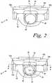
- FIGS. 2-3illustrate an end view of the lancing device 10 with the endcap 18 removed.
- a lancet holder 36includes a central, generally-cylindrical aperture 28 formed therein.
- the aperture 28is adapted to receive the lancet 30, as illustrated in FIG. 3 .
- the lancet 30includes a lancet body 32 with the sharp-tipped lance 34 extending therefrom.
- the lance 34may initially be enclosed within a protective cap 70 ( FIG. 9 ) to protect a user from unintended punctures. Additionally, the protective cap 70 assists with preventing or inhibiting the lance 34 from being contaminated prior to use and also may be replaced after the use of the lance 34, prior to discarding the lancet 30.
- FIG. 4a cross-sectional top view of the lancing device 10 in a resting position with the endcap 18 detached is illustrated.
- the lancet holder 36is connected to an elongated shaft 38 by being integrally formed therewith.
- the shaft 38has an retainer 40 that is supported within the movable housing 14.
- a drive spring 42is disposed around the shaft 38 between the lancet holder 36 and a spring stop 44 integrally formed with the first main-housing portion 12a.
- the movable housing 14has a pair of elongated columns 48a,b integrally formed therewith. Each of the columns 48a,b extends into the main housing 12 through an aperture (not shown) formed in the first main-housing portion 12a.
- a secondary spring 46is disposed around the shaft 38 within the movable housing 14. A first end of the secondary spring 46 is disposed against an internal surface of the movable housing 14 and a second end of the secondary spring 46 is disposed against the retainer 40 of the shaft 38.
- the secondary spring 46is centrally located within the movable housing 14 along the longitudinal axis of the lancing device 10.
- FIG. 4illustrates the interior of the lancing device 10 when the lancing device 10 is at rest. In this position, the lancet holder 36 is disposed in a rest position between a puncture position and a cocked position. In the rest position, both the drive spring 42 and the secondary spring 46 are substantially uncompressed and are in equilibrium with each other.
- FIG. 5illustrates the interior of the lancing device 10 (the lancet 30 is not shown) when the lancet holder 36 and movable housing 14 are in a cocking position in which the movable housing 14 has been pulled away from the main housing 12. In the cocking position, both the drive spring 42 and the secondary spring 46 are substantially compressed as the user moves the movable housing 14 away from the housing 12 in the direction of Arrow A.
- the movable housing 14is pulled away from the main housing 12 in the direction of Arrow A.
- the movable housing 14continues to be pulled-against the force of the drive spring 42 and the secondary spring 46-until a plurality of angled stop members 50a,b formed on the lancet holder 36 move past (to the right of as illustrated in FIGS. 4-6 ) a plurality of catch arms 52a,b located on the pushbutton 22 (as best illustrated in FIG. 8 ).
- Each of the catch arms 52a,bhas a respective end 53a,b adapted to engage the angled stop members 50a,b.
- the ends 53a,b of the catch arms 52a,bare angled opposite the angled stop members 50a,b, such that when the angled stop members 50a,b are moved in the direction of Arrow A they contact the ends 53a,b of the catch arms 52a,b.
- the movement of the angled stop members 50a,bforces the ends 53a,b of the catch arms 52a,b-as well as the attached pushbutton 22-in the direction of the first main housing portion 12a.
- a spring mechanism 82(illustrated in FIGS. 10a-c )-located between the second main-housing portion 12b and the pushbutton 22-forces the catch arms 52a,b towards the first main-housing portion 12a.
- This movementcauses the ends 53a,b of the catch arms 52a,b to engage the angled stop members 50a,b.
- movement of the lancet holder 36 in the direction of Arrow Bdue to the drive spring 42 is prevented.
- the userreleases the movable housing 14 and allows the now compressed secondary spring 46 to force the movable housing 14 back to its initial position adjacent the main housing 12, as illustrated in FIG. 6 .
- the lancing device 10is now in its cocked position, wherein the drive spring 42 is substantially compressed, and the secondary spring 46 is substantially decompressed.
- the lancet holder 36is guided between its resting and cocked positions by a guide rib 56 ( FIG. 9a ) formed on a portion of the lancet holder 36.
- the guide rib 56rides within a groove 58 ( FIGS. 5-6 and FIGS. 10a-10c ) formed between a pair of raised guide rails 60a,b ( FIGS. 5-6 ) formed in an interior portion of the first main-housing portion 12a.
- the endcap 18is attached to the lancing device 10.
- the lancet holder 36may be in the cocked position at the time the endcap 18 is attached or may be cocked once the endcap 18 has been removably attached to the endcap support 16.
- the endcap 18is then placed firmly against the skin where the puncture is to be made, and the pushbutton 22 is depressed. Depressing the pushbutton 22 causes the catch arms 52a,b ( FIG. 8 )-integrally formed with the bottom of the pushbutton 22-to move toward the first main-housing portion 12a away from the lancet holder 36.
- the spring mechanism 82 of FIGS. 10a-cfor example, one or more spring bars or an elastically deformable foam material-is formed on (or disposed between) the second main-housing portion 12b and the pushbutton 22 to bias the pushbutton 22 to its non-actuated position.
- the drive spring 42Upon release of the lancet holder 36 as described above, the drive spring 42 will force the lancet holder 36 in the direction of Arrow B until the sharp point of the lance 34 ( FIG. 4 ) passes through the aperture (not shown) in the endcap 18 to make the puncture.
- the attached shaft 38As the lancet holder 36 moves in the direction of Arrow B, the attached shaft 38 also moves in the direction of Arrow B.
- the retainer 40 of the shaft 38causes the secondary spring 46 to compress as the lancet holder 36 moves to the puncture position.
- the return force of the compressed secondary spring 46becomes greater than the puncture force of the drive spring 42.
- the secondary spring's 46 return forcecauses the lancet holder 36 to change direction and return to its rest position by moving in the direction of Arrow A.
- a stop membermay be provided to stop the lancet holder 36 from moving too far in the direction of Arrow B, at which time the secondary spring 46 returns the lancet holder 36 to its rest position.
- the lancet holder 36typically moves in the direction of Arrow A further than required to return to its rest position.
- slightly recompressing the drive spring 42which causes the lancet holder 36 to again travel in the direction of Arrow B.
- the secondary spring 46is recompressed.
- the force required to recompress the secondary spring 46effectively dampens the movement of the lancet holder 36.
- dampingassists in inhibiting or preventing the drive spring 42-and its natural tendency to oscillate (due to its being elastically deformable)-from causing a second, unintended skin puncture.
- the pushbutton 22includes a body 62 from which the two catch arms 52a,b extend. Each of the catch arms 52a,b includes an end 53a,b, respectively, opposite from the body 62. Each end 53a,b is adapted to engage an angled stop member 50a,b of the lancet holder 36.
- a lancet-release tab 76extends from the body 62 of the pushbutton 22 in the same direction as the catch arms 52a,b. The lancet-release tab 76 is adapted to extend through a slot 80 ( FIG. 9b ) formed in the lancet holder 36 when the pushbutton 22 is depressed towards the lancet holder 36.
- the lancet-release tab 76is adapted to engage the lancet 30 as will be described further below with respect to FIGS. 10a-c .
- the body 62 of the pushbuttonincludes a depression 22a ( FIGS. 1 and 8 ) or tactile features (not shown) to more easily allow a user to engage the pushbutton 22.
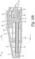
- FIGS. 9a-ba perspective view of the lancet 30 disposed within the lancet holder 36 is illustrated.
- the lancet 30is shown with the protective cap 70 that has a portion that is integrally formed with the lancet body 32 and which covers the sharp point of the lance 34.
- the lancet body 32 of a new lancet 30is inserted into the cylindrical aperture disposed in the lancet holder 36, and then the protective cap 70 is twisted off of the lancet assembly 30, in the direction of the Arrow C shown in FIG. 9a .
- the lancet holder 36includes the guide rib 56 that is adapted to be inserted into the groove 58 ( FIGS. 5-6 ).
- the guide rib 56 and groove 58are adapted to assist in providing a linear puncture of the test subject's skin by the lancet 30. Linear punctures are preferable because they tend to produce a less painful, and faster healing, piercing of the skin.
- the lancet holder 36includes the slot 80 that is adapted to receive the lancet-release tab 76 when the pushbutton 22 is depressed towards the lancet holder 36.
- the slot 80allows the lancet-release tab 76 to sufficiently enter the lancet holder 36 that the lancet-release tab 76 is capable or engaging the lancet 30 as will be further described with respect to FIGS. 10a-c .
- FIGS. 10a-cthe release of a lancet 30 from the lancet holder 36 is illustrated, according to one embodiment of the present invention.
- the lancing device 10is in its resting position with the drive spring 42 and secondary spring 46 being substantially decompressed.
- the pushbutton 22is also in its resting position and, as such, the lancet-release tab 76 does not extend into the slot 80 of the lancet holder 36.
- FIG. 10bthe lancing device 10 remains in its resting position, however, the pushbutton 22 has been depressed in the direction of the lancet holder 36 and the lancet-release tab 76 now extends into the slot 80 of the lancet holder 36.
- the lancet-release tab 76extends sufficiently into the lancet holder 36 to engage the lancet 30 received therein-as the lancing device 10 is moved to the lancet-release position illustrated in FIG. 10c .
- the lancing device 10is illustrated in its lancet-release position.
- the pushbutton 22is sufficiently depressed in the direction of the housing 12 to cause the lancet-release tab 76 to extend through the slot 80 and into the lancet holder 36.
- the movable housing 14is pulled away from the main housing 12 in the direction of Arrow A.
- the lancet holder 36moves in the direction of Arrow A as well-similar to the movement described above with respect to cocking the lancing device 10.
- the lancet-release tab 76engages the lancet 30 and inhibits the lancet 30 from moving in the direction of Arrow A.
- the lancet holder 36continues to move in the direction of Arrow A, the lancet 30 is removed from the lancet holder 36 without the user having to directly contact the lancet 30 with their hand.
- the userreleases the movable housing 14 and the secondary spring 46 causes the movable housing 14 to move in the direction of Arrow B until the movable housing 14 is once again adjacent the main housing 12.
- the lancet-release mechanismAs should be apparent from the above-described lancet-release mechanism, the potential for unintended punctures to the user is greatly diminished.
- the lancet-release mechanismis designed to be easily integrated into existing lancing devices 10 and, because of its unique design, is well-suited to stand the everyday use of a user of the lancing device 10 (e.g., carrying in a purse or pocket, dropping, inadvertent bumping, etc.).
- the secondary spring 46is used to both move the movable housing 14 from the cocking position to the cocked position as well as to return the lancet holder 36 from its puncture position to its rest position.
- the secondary spring 46is adapted to move the movable housing 14 from the lancet-release position to the rest position.
- the use of two opposing springsallows for the puncture strength to be adjusted by adjusting the spring ratio between the drive spring 42 and the secondary spring 46, reducing the need to compute the frictional interaction and mass of the various components of the device.
- the spring constant of the drive spring 42is greater than the spring constant of the secondary spring 46, which causes the secondary spring 46 to initially be compressed by the force provided by the drive spring 42.
- the structure of the above-described lancing device 10also allows for both the drive spring 42 and the secondary spring 46 to remain free floating on the shaft 38. Thus, the need for attaching one or both ends of each spring is eliminated, reducing the cost and time required to manufacture the lancing device 10.
- a lancing devicecomprising:
- a method of releasing a lancet from a lancing devicecomprising the acts of:
Landscapes
- Health & Medical Sciences (AREA)
- Life Sciences & Earth Sciences (AREA)
- Engineering & Computer Science (AREA)
- Heart & Thoracic Surgery (AREA)
- Molecular Biology (AREA)
- Pathology (AREA)
- Physics & Mathematics (AREA)
- Biomedical Technology (AREA)
- Hematology (AREA)
- Medical Informatics (AREA)
- Biophysics (AREA)
- Surgery (AREA)
- Animal Behavior & Ethology (AREA)
- General Health & Medical Sciences (AREA)
- Public Health (AREA)
- Veterinary Medicine (AREA)
- Manufacturing & Machinery (AREA)
- Dermatology (AREA)
- Measurement Of The Respiration, Hearing Ability, Form, And Blood Characteristics Of Living Organisms (AREA)
Description
- The present invention relates generally to diagnostic instruments and, more particularly, to a lancet-release mechanism for a lancing device.
- The quantitative determination of analytes in body fluids is of great importance in the diagnoses and maintenance of certain physiological abnormalities. For example, lactate, cholesterol and bilirubin should be monitored in certain individuals. In particular, determining glucose in body fluids is important to diabetic individuals who must frequently check their blood glucose levels to regulate the glucose intake in their diets.
- One method of obtaining a body fluid sample, such as a whole blood sample, is to use a lancing device. The whole blood sample may then be used to determine the glucose concentration of an individual. Existing lancing devices use a lancet to pierce the tissue of the skin, allowing a blood sample to form on the skin's surface. Typically, lancing devices hold the lancet within them when the lancet is not in use, so as to shield the user from injury as well as to assist in preventing or inhibiting contamination.
- Existing lancing devices require are potentially dangerous when-or are ineffective in-releasing the lancet. Typical two-handed operation requires that one hand hold the lancing device while the other hand removes the lancet. This is inconvenient to many users as the lancet is small, and may cause safety problems as the lancet could pierce the user's skin inadvertently. This can cause user pain and may also transmit diseases. Some lancet-release designs have complicated release mechanisms internally, such that if a user drops the lancing device, the release mechanism may jam and no longer eject the lancet from the lancing device. e.g.
US2005/0090850A involves a complicated release mechanism. - It would be desirable to have a lancing device and a method for using a lancing device that address these issues.
- According to one embodiment of the present invention, a lancing device is disclosed. The lancing device comprises a main housing, a movable housing, and a pushbutton. The main housing encloses a portion of a lancing mechanism including a lancet holder attached to a shaft. The lancet holder is adapted to receive a lancet and has a slot formed therein. The lancing mechanism is adapted to move between a rest position, a cocked position, and a puncture position. The movable housing is adjacent the main housing and is adapted to move from a rest position to a cocking position and a lancet-release position. The pushbutton is adapted to allow the lancing mechanism to move from the cocked position to the puncture position upon depression of the pushbutton in the general direction of the main housing. The pushbutton includes a lancet-release tab formed thereon. The lancet-release tab is adapted to extend into the slot formed in the lancet holder and engage the lancet. The lancet is released from the lancet holder in response to the continued depression of the pushbutton and the movable housing being moved from the rest position to the lancet-release position.
- According to another embodiment of the present invention, a method of releasing a lancet from a lancing device is disclosed. The method comprises the act of providing a lancing device including (i) a main housing enclosing a lancet holder being adapted to receive the lancet, the lancet holder having a slot formed therein, (ii) a movable housing adjacent the main housing, the movable housing being adapted to move from a rest position to a cocking position and a lancet-release position, and (iii) a pushbutton having a lancet-release tab formed thereon, the lancet-release tab being adapted to extend into the slot formed in the lancet holder and engage the lancet. The method further comprises the act depressing the pushbutton in the general direction of the main housing resulting in the lancet-release tab entering the slot formed in the lancet holder. The method further comprises the act of moving the movable housing from the rest position to the lancet-release position, while the pushbutton remains depressed. The movement of the movable housing causes the lancet-release tab to engage the lancet and cause the lancet to release from the lancet holder.
- The above summary of the present invention is not intended to represent each embodiment, or every aspect, of the present invention. Additional features and benefits of the present invention are apparent from the detailed description and figures set forth below.
FIG. 1 is a perspective view of a lancing device and endcap, according to one embodiment of the present invention.FIG. 2 is a front view of the lancing device ofFIG. 1 .FIG. 3 is a front view of the lancing device ofFIG. 1 with a lancet received therein.FIG. 4 is a cross-sectional view of the lancing device ofFIG. 1 taken generally along line 4-4 ofFIG. 3 with a lancet received therein, the lancing device being in a resting position.FIG. 5 is a cross-sectional view of the lancing device ofFIG. 1 taken generally along line 4-4 ofFIG. 3 in a cocking position.FIG. 6 is a cross-sectional view of the lancing device ofFIG. 1 taken generally along line 4-4 ofFIG. 3 in a cocked position.FIG. 7 is a cross-sectional view of the lancing device ofFIG. 1 taken generally along line 4-4 ofFIG. 3 in a puncture position.FIG. 8 is a front view of a pushbutton of the lancing device ofFIG. 1 , according to one embodiment of the present invention.FIGS. 9a-b are perspective views of a lancing mechanism contained within the lancing device ofFIG. 1 , according to one embodiment of the present invention.FIG. 10a is a cross-sectional side view of the lancing device-taken generally along line 10-10 ofFIG. 1 -in a cocked position, according to one embodiment of the present invention.FIG. 10b is a cross-sectional side view of the lancing device ofFIG. 10a in a resting position with a depressed pushbutton.FIG. 10c is a cross-sectional side view of the lancing device ofFIG. 10a in a lancet-release position.- The present invention is directed to a lancing device that is adapted to receive and release a lancet for use in drawing a body fluid from a test subject. The body fluid generally contains at least one analyte that may then be examined to determine its concentration in the body fluid sample.
- Lancing devices and lancets may be used to produce a blood or body fluid sample from a test subject. This sample may then be analyzed with a meter and test strip, or similar devices, to determine the concentration of the analyte to be examined. Examples of the types of analytes that may be collected with a lancing device include glucose, lipid profiles (e.g., cholesterol, triglycerides, LDL and HDL), microalbumin, hemoglobin A1C, fructose, lactate, or bilirubin.
- Turning now to the drawings and initially to
FIGS. 1-3 , alancing device 10 for obtaining a fluid sample from a test subject is illustrated, according to one embodiment of the present invention. Thelancing device 10 has amain housing 12 with amovable housing 14 movable relative to themain housing 12. Themain housing 12 includes a first main-housing portion 12a and a second main-housing portion 12b. The first and second main-housing portions 12a,b may be removeably attachable or may be formed or molded as one permanently attached piece. Anendcap support 16 is connected to themain housing 12 on the testing end of thelancing device 10. Anendcap 18 may be removably attached to theendcap support 16. When attached, theendcap 18 is retained on theendcap support 16 by, for example, a pair ofsupport arms 20a-b integrally formed with theendcap support 16. - When used, the
movable housing 14 is pulled away from themain housing 12 to move an internal lancing mechanism 24 (FIGS. 9a-b ) to a cocked position, and then a pushbutton 22 (as best illustrated inFIG. 8 ) is depressed to actuate the lancingmechanism 24 so that a sharp-tippedlance 34 of alancet 30 is forced through an aperture (not shown) formed in theendcap 18. The lancingdevice 10 may be provided with a number ofdifferent endcaps 18, each having a different width, to facilitate the formation of skin punctures of various depths. Alternatively, theendcap 18 may include anadjustable dial 26 for allowing punctures of different depths to be performed utilizing asingle endcap 18. FIGS. 2-3 illustrate an end view of the lancingdevice 10 with theendcap 18 removed. Alancet holder 36 includes a central, generally-cylindrical aperture 28 formed therein. Theaperture 28 is adapted to receive thelancet 30, as illustrated inFIG. 3 . Thelancet 30 includes alancet body 32 with the sharp-tippedlance 34 extending therefrom. Thelance 34 may initially be enclosed within a protective cap 70 (FIG. 9 ) to protect a user from unintended punctures. Additionally, theprotective cap 70 assists with preventing or inhibiting thelance 34 from being contaminated prior to use and also may be replaced after the use of thelance 34, prior to discarding thelancet 30.- Referring also to
FIG. 4 , a cross-sectional top view of the lancingdevice 10 in a resting position with theendcap 18 detached is illustrated. Thelancet holder 36 is connected to anelongated shaft 38 by being integrally formed therewith. Theshaft 38 has anretainer 40 that is supported within themovable housing 14. Adrive spring 42 is disposed around theshaft 38 between thelancet holder 36 and aspring stop 44 integrally formed with the first main-housing portion 12a. - The
movable housing 14 has a pair ofelongated columns 48a,b integrally formed therewith. Each of thecolumns 48a,b extends into themain housing 12 through an aperture (not shown) formed in the first main-housing portion 12a. Asecondary spring 46 is disposed around theshaft 38 within themovable housing 14. A first end of thesecondary spring 46 is disposed against an internal surface of themovable housing 14 and a second end of thesecondary spring 46 is disposed against theretainer 40 of theshaft 38. Thesecondary spring 46 is centrally located within themovable housing 14 along the longitudinal axis of the lancingdevice 10. FIG. 4 illustrates the interior of the lancingdevice 10 when the lancingdevice 10 is at rest. In this position, thelancet holder 36 is disposed in a rest position between a puncture position and a cocked position. In the rest position, both thedrive spring 42 and thesecondary spring 46 are substantially uncompressed and are in equilibrium with each other.FIG. 5 illustrates the interior of the lancing device 10 (thelancet 30 is not shown) when thelancet holder 36 andmovable housing 14 are in a cocking position in which themovable housing 14 has been pulled away from themain housing 12. In the cocking position, both thedrive spring 42 and thesecondary spring 46 are substantially compressed as the user moves themovable housing 14 away from thehousing 12 in the direction of Arrow A.- Referring now to
FIGS. 4-8 , to move thelancet holder 36 from its rest position to its cocked position, themovable housing 14 is pulled away from themain housing 12 in the direction of Arrow A. Themovable housing 14 continues to be pulled-against the force of thedrive spring 42 and the secondary spring 46-until a plurality ofangled stop members 50a,b formed on thelancet holder 36 move past (to the right of as illustrated inFIGS. 4-6 ) a plurality ofcatch arms 52a,b located on the pushbutton 22 (as best illustrated inFIG. 8 ). Each of thecatch arms 52a,b has arespective end 53a,b adapted to engage theangled stop members 50a,b. The ends 53a,b of thecatch arms 52a,b are angled opposite theangled stop members 50a,b, such that when theangled stop members 50a,b are moved in the direction of Arrow A they contact theends 53a,b of thecatch arms 52a,b. The movement of theangled stop members 50a,b forces theends 53a,b of thecatch arms 52a,b-as well as the attached pushbutton 22-in the direction of the firstmain housing portion 12a. - Once the
angled stop members 50a,b have moved past theends 53a,b of thecatch arms 52a,b, a spring mechanism 82 (illustrated inFIGS. 10a-c )-located between the second main-housing portion 12b and the pushbutton 22-forces thecatch arms 52a,b towards the first main-housing portion 12a. This movement causes theends 53a,b of thecatch arms 52a,b to engage theangled stop members 50a,b. In this position, movement of thelancet holder 36 in the direction of Arrow B (seeFIGS. 4-7 ) due to thedrive spring 42 is prevented. After theangled stop members 50a,b have been engaged, the user releases themovable housing 14 and allows the now compressedsecondary spring 46 to force themovable housing 14 back to its initial position adjacent themain housing 12, as illustrated inFIG. 6 . The lancingdevice 10 is now in its cocked position, wherein thedrive spring 42 is substantially compressed, and thesecondary spring 46 is substantially decompressed. - The
lancet holder 36 is guided between its resting and cocked positions by a guide rib 56 (FIG. 9a ) formed on a portion of thelancet holder 36. Theguide rib 56 rides within a groove 58 (FIGS. 5-6 andFIGS. 10a-10c ) formed between a pair of raisedguide rails 60a,b (FIGS. 5-6 ) formed in an interior portion of the first main-housing portion 12a. - To perform a puncture on a test subject's skin, the
endcap 18 is attached to the lancingdevice 10. Thelancet holder 36 may be in the cocked position at the time theendcap 18 is attached or may be cocked once theendcap 18 has been removably attached to theendcap support 16. Theendcap 18 is then placed firmly against the skin where the puncture is to be made, and thepushbutton 22 is depressed. Depressing thepushbutton 22 causes thecatch arms 52a,b (FIG. 8 )-integrally formed with the bottom of the pushbutton 22-to move toward the first main-housing portion 12a away from thelancet holder 36. Thus, thelancet holder 36 is no longer prevented from moving in the direction of Arrow B by the contact of theends 53a,b of thecatch arms 52a,b with theangled stop members 50a,b of thelancet holder 36. Thespring mechanism 82 ofFIGS. 10a-c -for example, one or more spring bars or an elastically deformable foam material-is formed on (or disposed between) the second main-housing portion 12b and thepushbutton 22 to bias thepushbutton 22 to its non-actuated position. - Upon release of the
lancet holder 36 as described above, thedrive spring 42 will force thelancet holder 36 in the direction of Arrow B until the sharp point of the lance 34 (FIG. 4 ) passes through the aperture (not shown) in theendcap 18 to make the puncture. As thelancet holder 36 moves in the direction of Arrow B, the attachedshaft 38 also moves in the direction of Arrow B. Theretainer 40 of theshaft 38 causes thesecondary spring 46 to compress as thelancet holder 36 moves to the puncture position. As the lancingmechanism 24 reaches the puncture position (FIG. 7 ), the return force of the compressedsecondary spring 46 becomes greater than the puncture force of thedrive spring 42. At this point, the secondary spring's 46 return force causes thelancet holder 36 to change direction and return to its rest position by moving in the direction of Arrow A. Alternatively, in some embodiments, a stop member may be provided to stop thelancet holder 36 from moving too far in the direction of Arrow B, at which time thesecondary spring 46 returns thelancet holder 36 to its rest position. - However, the
lancet holder 36 typically moves in the direction of Arrow A further than required to return to its rest position. Thus, slightly recompressing thedrive spring 42, which causes thelancet holder 36 to again travel in the direction of Arrow B. As thelancet holder 36 begins to move back in the direction of Arrow B (due to the slight recompression of the drive spring 42), thesecondary spring 46 is recompressed. The force required to recompress thesecondary spring 46 effectively dampens the movement of thelancet holder 36. Such damping assists in inhibiting or preventing the drive spring 42-and its natural tendency to oscillate (due to its being elastically deformable)-from causing a second, unintended skin puncture. - Turning now to
FIG. 8 , thepushbutton 22 is illustrated according to one embodiment of the present invention. Thepushbutton 22 includes abody 62 from which the twocatch arms 52a,b extend. Each of thecatch arms 52a,b includes anend 53a,b, respectively, opposite from thebody 62. Eachend 53a,b is adapted to engage anangled stop member 50a,b of thelancet holder 36. A lancet-release tab 76 extends from thebody 62 of thepushbutton 22 in the same direction as thecatch arms 52a,b. The lancet-release tab 76 is adapted to extend through a slot 80 (FIG. 9b ) formed in thelancet holder 36 when thepushbutton 22 is depressed towards thelancet holder 36. The lancet-release tab 76 is adapted to engage thelancet 30 as will be described further below with respect toFIGS. 10a-c . Thebody 62 of the pushbutton includes adepression 22a (FIGS. 1 and8 ) or tactile features (not shown) to more easily allow a user to engage thepushbutton 22. - Turning now to
FIGS. 9a-b , a perspective view of thelancet 30 disposed within thelancet holder 36 is illustrated. Thelancet 30 is shown with theprotective cap 70 that has a portion that is integrally formed with thelancet body 32 and which covers the sharp point of thelance 34. Prior to using the lancingdevice 10, thelancet body 32 of anew lancet 30 is inserted into the cylindrical aperture disposed in thelancet holder 36, and then theprotective cap 70 is twisted off of thelancet assembly 30, in the direction of the Arrow C shown inFIG. 9a . - The
lancet holder 36 includes theguide rib 56 that is adapted to be inserted into the groove 58 (FIGS. 5-6 ). Theguide rib 56 andgroove 58 are adapted to assist in providing a linear puncture of the test subject's skin by thelancet 30. Linear punctures are preferable because they tend to produce a less painful, and faster healing, piercing of the skin. - As best illustrated in
FIG. 9b , thelancet holder 36 includes theslot 80 that is adapted to receive the lancet-release tab 76 when thepushbutton 22 is depressed towards thelancet holder 36. Theslot 80 allows the lancet-release tab 76 to sufficiently enter thelancet holder 36 that the lancet-release tab 76 is capable or engaging thelancet 30 as will be further described with respect toFIGS. 10a-c . - Turning now to
FIGS. 10a-c , the release of alancet 30 from thelancet holder 36 is illustrated, according to one embodiment of the present invention. InFIG. 10a , the lancingdevice 10 is in its resting position with thedrive spring 42 andsecondary spring 46 being substantially decompressed. Thepushbutton 22 is also in its resting position and, as such, the lancet-release tab 76 does not extend into theslot 80 of thelancet holder 36. Referring now toFIG. 10b , the lancingdevice 10 remains in its resting position, however, thepushbutton 22 has been depressed in the direction of thelancet holder 36 and the lancet-release tab 76 now extends into theslot 80 of thelancet holder 36. The lancet-release tab 76 extends sufficiently into thelancet holder 36 to engage thelancet 30 received therein-as the lancingdevice 10 is moved to the lancet-release position illustrated inFIG. 10c . - Referring now to
FIG. 10c , the lancingdevice 10 is illustrated in its lancet-release position. In this position, thepushbutton 22 is sufficiently depressed in the direction of thehousing 12 to cause the lancet-release tab 76 to extend through theslot 80 and into thelancet holder 36. Once thepushbutton 22 has been depressed, themovable housing 14 is pulled away from themain housing 12 in the direction of Arrow A. As themovable housing 14 is pulled away from themain housing 12, thelancet holder 36 moves in the direction of Arrow A as well-similar to the movement described above with respect to cocking the lancingdevice 10. - As the
lancet holder 36 moves in the direction of Arrow A, the lancet-release tab 76 engages thelancet 30 and inhibits thelancet 30 from moving in the direction of Arrow A. As thelancet holder 36 continues to move in the direction of Arrow A, thelancet 30 is removed from thelancet holder 36 without the user having to directly contact thelancet 30 with their hand. Once thelancet 30 has been released, the user releases themovable housing 14 and thesecondary spring 46 causes themovable housing 14 to move in the direction of Arrow B until themovable housing 14 is once again adjacent themain housing 12. - As should be apparent from the above-described lancet-release mechanism, the potential for unintended punctures to the user is greatly diminished. In addition, the lancet-release mechanism is designed to be easily integrated into existing lancing
devices 10 and, because of its unique design, is well-suited to stand the everyday use of a user of the lancing device 10 (e.g., carrying in a purse or pocket, dropping, inadvertent bumping, etc.). - In the above-described
lancing device 10, thesecondary spring 46 is used to both move themovable housing 14 from the cocking position to the cocked position as well as to return thelancet holder 36 from its puncture position to its rest position. In addition, thesecondary spring 46 is adapted to move themovable housing 14 from the lancet-release position to the rest position. - The use of two opposing springs allows for the puncture strength to be adjusted by adjusting the spring ratio between the
drive spring 42 and thesecondary spring 46, reducing the need to compute the frictional interaction and mass of the various components of the device. Typically, the spring constant of thedrive spring 42 is greater than the spring constant of thesecondary spring 46, which causes thesecondary spring 46 to initially be compressed by the force provided by thedrive spring 42. - The structure of the above-described
lancing device 10 also allows for both thedrive spring 42 and thesecondary spring 46 to remain free floating on theshaft 38. Thus, the need for attaching one or both ends of each spring is eliminated, reducing the cost and time required to manufacture the lancingdevice 10. - A lancing device comprising:
- a main housing enclosing a portion of a lancing mechanism, the lancing mechanism including a lancet holder attached to a shaft, the lancet holder being adapted to receive a lancet and having a slot formed therein, the lancing mechanism being adapted to move between a rest position, a cocked position, and a puncture position;
- a movable housing adjacent the main housing, the movable housing being adapted to move from a rest position to a cocking position and a lancet-release position; and
- a pushbutton adapted to allow the lancing mechanism to move from the cocked position to the puncture position upon depression of the pushbutton in the general direction of the main housing, the pushbutton including a lancet-release tab formed thereon, the lancet-release tab being adapted to extend into the slot formed in the lancet holder and engage the lancet,
- wherein the lancet is released from the lancet holder in response to the continued depression of the pushbutton and the movable housing being moved from the rest position to the lancet-release position.
- The lancing device of Alternative Embodiment A, wherein the pushbutton of the lancet-release mechanism includes a depression that assists a user in engaging the pushbutton.
- The lancing device of Alternative Embodiment A, wherein the pushbutton of the lancet-release mechanism includes tactile features that assist a user in engaging the pushbutton.
- The lancing device of Alternative Embodiment A, wherein the lancet-release tab does not engage the lancet until the movable housing is moved from the rest position to the lancet-release position.
- The lancing device of Alternative Embodiment A, wherein the cocking position and the lancet-release position of the movable housing are substantially identical.
- A method of releasing a lancet from a lancing device, the method comprising the acts of:
- providing a lancing device including,
- (i) a main housing enclosing a lancet holder being adapted to receive the lancet, the lancet holder having a slot formed therein,
- (ii) a movable housing adjacent the main housing, the movable housing being adapted to move from a rest position to a cocking position and a lancet-release position, and
- (iii) a pushbutton having a lancet-release tab formed thereon, the lancet-release tab being adapted to extend into the slot formed in the lancet holder and engage the lancet;
- depressing the pushbutton in the general direction of the main housing resulting in the lancet-release tab entering the slot formed in the lancet holder; and
- moving the movable housing from the rest position to the lancet-release position, while the pushbutton remains depressed, the moving of the movable housing causing the lancet-release tab to engage the lancet and cause the lancet to release from the lancet holder.
- The method of Alternative Process F, further comprising the act of removing the lancet from the lancet holder without a user touching the lancet.
- The method of Alternative Process F, wherein the pushbutton is also adapted to fire the lancing device.
- The method of Alternative Process H, wherein the pushbutton is utilized to release the lancet from the lancet holder.
- The method of Alternative Process F, wherein the cocking position and the lancet-release position of the movable housing are substantially identical.
- While the invention is susceptible to various modifications and alternative forms, specific embodiments and methods thereof have been shown by way of example in the drawings and are described in detail herein. It should be understood, however, that it is not intended to limit the invention to the particular forms or methods disclosed, but, to the contrary, the intention is to cover all modifications, equivalents and alternatives falling within the spirit and scope of the invention as defined by the appended claims.
Claims (10)
- A lancing device (10) comprising:a main housing (12) enclosing a portion of a lancing mechanism (24), the lancing mechanism (24) including a lancet holder (36) attached to a shaft (38), the lancet holder (34) being adapted to receive a lancet (30) and having a slot (80) formed therein, the lancing mechanism (24) being adapted to move between a rest position, a cocked position, and a puncture position;a movable housing (14) adjacent the main housing (12), the movable housing (14) being adapted to move from a rest position to a cocking position and a lancet-release position; anda pushbutton (22) adapted to allow the lancing mechanism (24) to move from the cocked position to the puncture position upon depression of the pushbutton (22) in the general direction of the interior of the main housing;characterized in the pushbutton (22) including a lancet-release tab (76) formed thereon, the lancet-release tab (76) being adapted to extend into the slot (80) formed in the lancet holder (36) and engage the lancet (30),wherein the lancet (30) is released from the lancet holder (36) in response to the continued depression of the pushbutton (22) and the movable housing (14) being moved from the rest position to the lancet-release position.
- The lancing device of claim 1, wherein the pushbutton (22) of the lancet-release mechanism includes a depression (22a) that assists a user in engaging the pushbutton.
- The lancing device of claim 1, wherein the pushbutton (22) of the lancet-release mechanism includes tactile features that assist a user in engaging the pushbutton.
- The lancing device of claim 1, wherein the lancet-release tab (76) does not engage the lancet (30) until the movable housing (14) is moved from the rest position to the lancet-release position.
- The lancing device of claim 1, wherein the cocking position and the lancet-release position of the movable housing are substantially identical.
- A method of releasing a lancet (30) from a lancing device (10), the method comprising the acts of:providing a lancing device (10) including,(i) a main housing (12) enclosing a lancet holder (36) being adapted to receive the lancet (30), the lancet holder (36) having a slot (80) formed therein,(ii) a movable housing (14) adjacent the main housing (12), the movable housing (14) being adapted to move from a rest position to a cocking position and a lancet-release position, and(iii) a pushbutton (22) having a lancet-release tab (76) formed thereon, the lancet-release tab (76) being adapted to extend into the slot (80) formed in the lancet holder (36) and engage the lancet (30);depressing the pushbutton (22) in the general direction of of the interior of the main housing (12) resulting in the lancet-release tab (76) entering the slot (80) formed in the lancet holder (36); andmoving the movable housing (14) from the rest position to the lancet-release position, while the pushbutton (22) remains depressed, the moving of the movable housing (14) causing the lancet-release tab (16) to engage the lancet (30) and cause the lancet (30) to release from the lancet holder (36).
- The method of claim 6, further comprising the act of removing the lancet from the lancet holder without a user touching the lancet.
- The method of claim 6, wherein the pushbutton (22) is also adapted to fire the lancing device.
- The method of claim 8, wherein the pushbutton (22) is utilized to release the lancet from the lancet holder.
- The method of claim 6, wherein the cocking position and the lancet-release position of the movable housing are substantially identical.
Applications Claiming Priority (1)
| Application Number | Priority Date | Filing Date | Title |
|---|---|---|---|
| PCT/US2007/006225WO2008111936A1 (en) | 2007-03-12 | 2007-03-12 | Lancet-eject mechanism |
Publications (2)
| Publication Number | Publication Date |
|---|---|
| EP2144563A1 EP2144563A1 (en) | 2010-01-20 |
| EP2144563B1true EP2144563B1 (en) | 2016-05-18 |
Family
ID=38608753
Family Applications (1)
| Application Number | Title | Priority Date | Filing Date |
|---|---|---|---|
| EP07752893.3AActiveEP2144563B1 (en) | 2007-03-12 | 2007-03-12 | Lancet-eject mechanism |
Country Status (5)
| Country | Link |
|---|---|
| US (1) | US8303615B2 (en) |
| EP (1) | EP2144563B1 (en) |
| ES (1) | ES2587021T3 (en) |
| NO (1) | NO20093132L (en) |
| WO (1) | WO2008111936A1 (en) |
Families Citing this family (17)
| Publication number | Priority date | Publication date | Assignee | Title |
|---|---|---|---|---|
| CN101163446A (en) | 2005-03-04 | 2008-04-16 | 拜尔保健有限公司 | Lancet-release mechanism |
| US8784444B2 (en)* | 2005-03-04 | 2014-07-22 | Bayer Healthcare Llc | Lancet release mechanism |
| GB2489740A (en) | 2011-04-08 | 2012-10-10 | Owen Mumford Ltd | Means for securely retaining a lancet in a lancing device |
| USD692997S1 (en)* | 2011-11-08 | 2013-11-05 | Becton Dickinson France, S.A.S. | Microinfuser |
| USD693455S1 (en)* | 2011-11-08 | 2013-11-12 | Becton, Dickinson And Company | Microinfuser |
| USD692552S1 (en)* | 2011-11-08 | 2013-10-29 | Becton Dickinson France, S.A.S. | Microinfuser |
| USD681195S1 (en)* | 2011-12-09 | 2013-04-30 | 3M Innovative Properties Company | Microstructure applicator |
| EP2836125B1 (en)* | 2012-04-12 | 2016-06-08 | Facet Technologies, LLC | Lancing device with side activated charge and eject mechanisms |
| USD774640S1 (en) | 2015-07-30 | 2016-12-20 | Becton, Dickinson And Company | Medical injector |
| USD776262S1 (en) | 2015-07-30 | 2017-01-10 | Becton, Dickinson And Company | Medical injector |
| USD776263S1 (en) | 2015-07-30 | 2017-01-10 | Becton, Dickinson And Company | Medical injector |
| USD776265S1 (en) | 2015-07-30 | 2017-01-10 | Becton, Dickinson And Company | Medical injector |
| USD776264S1 (en) | 2015-07-30 | 2017-01-10 | Becton, Dickinson And Company | Medical injector |
| USD767120S1 (en) | 2015-07-30 | 2016-09-20 | Becton, Dickinson And Company | Medical injector |
| USD794776S1 (en) | 2015-07-30 | 2017-08-15 | Becton, Dickinson And Company | Medical injector |
| EP3648677B1 (en) | 2017-07-06 | 2025-02-26 | Park Surgical Innovations, Llc | Device for delivering grafts at a surgical site |
| US11090145B2 (en) | 2017-07-06 | 2021-08-17 | Park Surgical Innovations, Llc | Device for delivering grafts at a surgical site and method |
Family Cites Families (90)
| Publication number | Priority date | Publication date | Assignee | Title |
|---|---|---|---|---|
| DE459483C (en) | 1928-05-07 | Ehrhard Henke | Device for taking blood samples from the human or animal body | |
| US3797488A (en)* | 1972-07-10 | 1974-03-19 | Ampoules Inc | Ampoule applicator with one-way clutch |
| DE2642896C3 (en)* | 1976-09-24 | 1980-08-21 | 7800 Freiburg | Precision snapper for setting standard stab wounds in the skin for diagnostic purposes |
| DE3011211A1 (en)* | 1980-03-22 | 1981-10-01 | Clinicon Mannheim GmbH, 6800 Mannheim | BLOOD PLANT DEVICE FOR TAKING BLOOD FOR DIAGNOSTIC PURPOSES |
| US4535769A (en)* | 1981-03-23 | 1985-08-20 | Becton, Dickinson And Company | Automatic retractable lancet assembly |
| FR2508305B1 (en)* | 1981-06-25 | 1986-04-11 | Slama Gerard | DEVICE FOR CAUSING A LITTLE BITE TO COLLECT A BLOOD DROP |
| US4449529A (en)* | 1981-11-18 | 1984-05-22 | Becton Dickinson And Company | Automatic retractable lancet assembly |
| USRE32922E (en)* | 1983-01-13 | 1989-05-16 | Paul D. Levin | Blood sampling instrument |
| US4517978A (en) | 1983-01-13 | 1985-05-21 | Levin Paul D | Blood sampling instrument |
| US4616649A (en) | 1984-09-20 | 1986-10-14 | Becton, Dickinson And Company | Lancet |
| US4627445A (en)* | 1985-04-08 | 1986-12-09 | Garid, Inc. | Glucose medical monitoring system |
| US5279294A (en)* | 1985-04-08 | 1994-01-18 | Cascade Medical, Inc. | Medical diagnostic system |
| US4787398A (en)* | 1985-04-08 | 1988-11-29 | Garid, Inc. | Glucose medical monitoring system |
| USD297459S (en)* | 1985-11-04 | 1988-08-30 | Miles Inc. | Lancet |
| US4735203A (en)* | 1986-12-12 | 1988-04-05 | Ryder International Corporation | Retractable lancet |
| US4924879A (en)* | 1988-10-07 | 1990-05-15 | Brien Walter J O | Blood lancet device |
| US4990154A (en)* | 1989-06-19 | 1991-02-05 | Miles Inc. | Lancet assembly |
| US4976724A (en)* | 1989-08-25 | 1990-12-11 | Lifescan, Inc. | Lancet ejector mechanism |
| USD332490S (en)* | 1990-04-12 | 1993-01-12 | Miles Inc. | Disposable lancet cap |
| US5196025A (en)* | 1990-05-21 | 1993-03-23 | Ryder International Corporation | Lancet actuator with retractable mechanism |
| US5231993A (en)* | 1991-11-20 | 1993-08-03 | Habley Medical Technology Corporation | Blood sampler and component tester with guide member |
| JP2572823Y2 (en)* | 1992-02-13 | 1998-05-25 | 株式会社アドバンス | Simple blood sampler |
| DE4212315A1 (en)* | 1992-04-13 | 1993-10-14 | Boehringer Mannheim Gmbh | Blood lancet device for drawing blood for diagnostic purposes |
| US5318583A (en) | 1992-05-05 | 1994-06-07 | Ryder International Corporation | Lancet actuator mechanism |
| US5267963A (en)* | 1992-08-21 | 1993-12-07 | Nicholas Bachynsky | Medication injection device |
| CA2079192C (en)* | 1992-09-25 | 1995-12-26 | Bernard Strong | Combined lancet and multi-function cap and lancet injector for use therewith |
| DE4320463A1 (en)* | 1993-06-21 | 1994-12-22 | Boehringer Mannheim Gmbh | Blood lancet device for drawing blood for diagnostic purposes |
| US5304193A (en)* | 1993-08-12 | 1994-04-19 | Sam Zhadanov | Blood lancing device |
| CA2135706C (en)* | 1993-11-15 | 1999-06-15 | Walter E. Cover | Retractable-needle cannula insertion set with refinements to better control leakage, retraction speed, and reuse |
| US5350392A (en)* | 1994-02-03 | 1994-09-27 | Miles Inc. | Lancing device with automatic cocking |
| US5527334A (en)* | 1994-05-25 | 1996-06-18 | Ryder International Corporation | Disposable, retractable lancet |
| US5628764A (en)* | 1995-03-21 | 1997-05-13 | Schraga; Steven | Collar lancet device |
| DE19604156A1 (en)* | 1996-02-06 | 1997-08-07 | Boehringer Mannheim Gmbh | Skin cutting device for taking pain-free small amounts of blood |
| US5951492A (en)* | 1996-05-17 | 1999-09-14 | Mercury Diagnostics, Inc. | Methods and apparatus for sampling and analyzing body fluid |
| US5951493A (en)* | 1997-05-16 | 1999-09-14 | Mercury Diagnostics, Inc. | Methods and apparatus for expressing body fluid from an incision |
| EP1862116A3 (en)* | 1996-05-17 | 2009-02-25 | Roche Diagnostics Operations, Inc. | Disposable element for use in a body fluid sampling device |
| US5741288A (en)* | 1996-06-27 | 1998-04-21 | Chemtrak, Inc. | Re-armable single-user safety finger stick device having reset for multiple use by a single patient |
| GB9616953D0 (en)* | 1996-08-13 | 1996-09-25 | Owen Mumford Ltd | Improvements relating to skin prickers |
| US5797942A (en)* | 1996-09-23 | 1998-08-25 | Schraga; Steven | Re-usable end cap for re-usable lancet devices for removing and disposing of a contaminated lancet |
| US5693023A (en)* | 1996-11-15 | 1997-12-02 | Adventec, Inc. | Syringe with retractable needle assembly |
| US6027459A (en)* | 1996-12-06 | 2000-02-22 | Abbott Laboratories | Method and apparatus for obtaining blood for diagnostic tests |
| USD393717S (en)* | 1997-03-21 | 1998-04-21 | Bayer Corporation | Lancet endcap pointer |
| USD393716S (en)* | 1997-03-24 | 1998-04-21 | Bayer Corporation | Lancet endcap |
| US5916230A (en)* | 1997-06-16 | 1999-06-29 | Bayer Corporation | Blood sampling device with adjustable end cap |
| US5868772A (en)* | 1997-07-31 | 1999-02-09 | Bayer Corporation | Blood sampling device with anti-twist lancet holder |
| US5954738A (en)* | 1997-07-31 | 1999-09-21 | Bayer Corporation | Blood sampling device with lancet damping system |
| US6090078A (en)* | 1997-09-30 | 2000-07-18 | Becton, Dickinson And Company | Dampening devices and methods for needle retracting safety vascular access devices |
| US6706000B2 (en)* | 1997-11-21 | 2004-03-16 | Amira Medical | Methods and apparatus for expressing body fluid from an incision |
| DE19824036A1 (en)* | 1997-11-28 | 1999-06-02 | Roche Diagnostics Gmbh | Analytical measuring device with lancing device |
| US5871494A (en)* | 1997-12-04 | 1999-02-16 | Hewlett-Packard Company | Reproducible lancing for sampling blood |
| US6022366A (en)* | 1998-06-11 | 2000-02-08 | Stat Medical Devices Inc. | Lancet having adjustable penetration depth |
| JP4250699B2 (en) | 1998-12-16 | 2009-04-08 | アークレイ株式会社 | A lancet device that can safely remove the lancet |
| US6197040B1 (en)* | 1999-02-23 | 2001-03-06 | Lifescan, Inc. | Lancing device having a releasable connector |
| US6045567A (en)* | 1999-02-23 | 2000-04-04 | Lifescan Inc. | Lancing device causing reduced pain |
| DE19909602A1 (en)* | 1999-03-05 | 2000-09-07 | Roche Diagnostics Gmbh | Device for drawing blood for diagnostic purposes |
| US6306152B1 (en)* | 1999-03-08 | 2001-10-23 | Agilent Technologies, Inc. | Lancet device with skin movement control and ballistic preload |
| US6231531B1 (en)* | 1999-04-09 | 2001-05-15 | Agilent Technologies, Inc. | Apparatus and method for minimizing pain perception |
| US6152942A (en)* | 1999-06-14 | 2000-11-28 | Bayer Corporation | Vacuum assisted lancing device |
| SG85117A1 (en)* | 1999-06-18 | 2001-12-19 | Surgilance Pte Ltd | Lancet assembly |
| US6168606B1 (en)* | 1999-11-10 | 2001-01-02 | Palco Labs, Inc. | Single-use lancet device |
| US6558402B1 (en)* | 1999-08-03 | 2003-05-06 | Becton, Dickinson And Company | Lancer |
| DE19948759A1 (en)* | 1999-10-09 | 2001-04-12 | Roche Diagnostics Gmbh | Blood lancet device for drawing blood for diagnostic purposes |
| US6283982B1 (en)* | 1999-10-19 | 2001-09-04 | Facet Technologies, Inc. | Lancing device and method of sample collection |
| CA2287757A1 (en)* | 1999-10-29 | 2001-04-29 | Medical Plastic Devices M.P.D. Inc. | Disposable lancet |
| US6364889B1 (en)* | 1999-11-17 | 2002-04-02 | Bayer Corporation | Electronic lancing device |
| KR200199396Y1 (en)* | 2000-05-25 | 2000-10-02 | 이춘발 | Lancet with safety structure of blood collection needle |
| US6607543B2 (en)* | 2000-06-13 | 2003-08-19 | Bayer Corporation | Lancing mechanism |
| DE10030410C1 (en)* | 2000-06-21 | 2002-01-24 | Roche Diagnostics Gmbh | Blood lancet device for drawing blood for diagnostic purposes |
| US6561989B2 (en)* | 2000-07-10 | 2003-05-13 | Bayer Healthcare, Llc | Thin lance and test sensor having same |
| TW495353B (en)* | 2000-09-01 | 2002-07-21 | Bayer Ag | Adjustable endcap for lancing device |
| US6514270B1 (en)* | 2000-11-10 | 2003-02-04 | Steven Schraga | Single use lancet device |
| US20020087180A1 (en)* | 2000-12-29 | 2002-07-04 | Searle Stephen D. | Blood lancet |
| US6752817B2 (en)* | 2001-03-26 | 2004-06-22 | Bayer Corporation | Split pressure ring for lancing device and method of operation |
| CA2461370A1 (en)* | 2001-09-26 | 2003-05-15 | F. Hoffmann-La Roche Ag | Method and apparatus for sampling bodily fluid |
| CA2419199A1 (en)* | 2002-03-05 | 2003-09-05 | Bayer Healthcare, Llc | Minimum invasive optical format with integrated lance |
| CA2419200C (en)* | 2002-03-05 | 2015-06-30 | Bayer Healthcare Llc | Fluid collection apparatus having an integrated lance and reaction area |
| DE10222235A1 (en)* | 2002-05-16 | 2003-11-27 | Roche Diagnostics Gmbh | Blood Collection system |
| JP4257943B2 (en) | 2002-07-29 | 2009-04-30 | アークレイ株式会社 | Puncture unit and puncture member removal tool |
| CA2444630A1 (en)* | 2002-10-15 | 2004-04-15 | Bayer Healthcare Llc | Lancing device |
| US7303573B2 (en)* | 2003-05-29 | 2007-12-04 | Abbott Laboratories | Lancet device |
| US20040248312A1 (en)* | 2003-06-06 | 2004-12-09 | Bayer Healthcare, Llc | Sensor with integrated lancet |
| WO2005011496A1 (en)* | 2003-07-31 | 2005-02-10 | Matsushita Electric Industrial Co., Ltd. | Puncturing instrument, puncturing needle cartridge, puncturing instrument set, and puncturing needle discardment instrument |
| DE10336933B4 (en)* | 2003-08-07 | 2007-04-26 | Roche Diagnostics Gmbh | Blood Collection system |
| JP2005111135A (en)* | 2003-10-10 | 2005-04-28 | Asahi Polyslider Co Ltd | Lancet cassette and lancet projection device, and lancet assembly composed of these |
| US20050085840A1 (en)* | 2003-10-15 | 2005-04-21 | Surgilance Pte Ltd | Lancet assembly |
| CN101163446A (en)* | 2005-03-04 | 2008-04-16 | 拜尔保健有限公司 | Lancet-release mechanism |
| EP1865847A1 (en)* | 2005-03-04 | 2007-12-19 | Bayer HealthCare LLC | Lancet-release mechanism |
| US8784444B2 (en)* | 2005-03-04 | 2014-07-22 | Bayer Healthcare Llc | Lancet release mechanism |
| US20060241669A1 (en)* | 2005-04-04 | 2006-10-26 | Stout Jeffrey T | Narrow-profile lancing device |
| US20060247670A1 (en)* | 2005-05-02 | 2006-11-02 | Levaughn Richard W | Lancing device with automatic lancet release |
- 2007
- 2007-03-12USUS12/530,654patent/US8303615B2/enactiveActive
- 2007-03-12ESES07752893.3Tpatent/ES2587021T3/enactiveActive
- 2007-03-12WOPCT/US2007/006225patent/WO2008111936A1/enactiveApplication Filing
- 2007-03-12EPEP07752893.3Apatent/EP2144563B1/enactiveActive
- 2009
- 2009-10-12NONO20093132Apatent/NO20093132L/ennot_activeApplication Discontinuation
Also Published As
| Publication number | Publication date |
|---|---|
| US8303615B2 (en) | 2012-11-06 |
| WO2008111936A1 (en) | 2008-09-18 |
| ES2587021T3 (en) | 2016-10-20 |
| NO20093132L (en) | 2009-11-11 |
| EP2144563A1 (en) | 2010-01-20 |
| US20100179579A1 (en) | 2010-07-15 |
Similar Documents
| Publication | Publication Date | Title |
|---|---|---|
| EP2144563B1 (en) | Lancet-eject mechanism | |
| EP1713391B1 (en) | Dampening and retraction mechanism for a lancing device | |
| US9622688B2 (en) | Lancet-release mechanism | |
| US20080167673A1 (en) | Lancet Release Mechanism | |
| US9055898B2 (en) | Lancet release mechanism | |
| US8864783B2 (en) | Lancing device | |
| US20090131966A1 (en) | Single-puncture lancing system | |
| US8940006B2 (en) | Single-puncture lancing system | |
| MXPA06008844A (en) | Dampening and retraction mechanism for a lancing device |
Legal Events
| Date | Code | Title | Description |
|---|---|---|---|
| PUAI | Public reference made under article 153(3) epc to a published international application that has entered the european phase | Free format text:ORIGINAL CODE: 0009012 | |
| 17P | Request for examination filed | Effective date:20091012 | |
| AK | Designated contracting states | Kind code of ref document:A1 Designated state(s):AT BE BG CH CY CZ DE DK EE ES FI FR GB GR HU IE IS IT LI LT LU LV MC MT NL PL PT RO SE SI SK TR | |
| AX | Request for extension of the european patent | Extension state:AL BA HR MK RS | |
| DAX | Request for extension of the european patent (deleted) | ||
| RAP1 | Party data changed (applicant data changed or rights of an application transferred) | Owner name:BAYER HEALTHCARE LLC | |
| 17Q | First examination report despatched | Effective date:20131107 | |
| GRAP | Despatch of communication of intention to grant a patent | Free format text:ORIGINAL CODE: EPIDOSNIGR1 | |
| INTG | Intention to grant announced | Effective date:20151021 | |
| GRAS | Grant fee paid | Free format text:ORIGINAL CODE: EPIDOSNIGR3 | |
| GRAA | (expected) grant | Free format text:ORIGINAL CODE: 0009210 | |
| RAP1 | Party data changed (applicant data changed or rights of an application transferred) | Owner name:ASCENSIA DIABETES CARE HOLDING AG | |
| AK | Designated contracting states | Kind code of ref document:B1 Designated state(s):AT BE BG CH CY CZ DE DK EE ES FI FR GB GR HU IE IS IT LI LT LU LV MC MT NL PL PT RO SE SI SK TR | |
| REG | Reference to a national code | Ref country code:GB Ref legal event code:FG4D | |
| REG | Reference to a national code | Ref country code:CH Ref legal event code:EP | |
| REG | Reference to a national code | Ref country code:IE Ref legal event code:FG4D Ref country code:AT Ref legal event code:REF Ref document number:799682 Country of ref document:AT Kind code of ref document:T Effective date:20160615 | |
| REG | Reference to a national code | Ref country code:DE Ref legal event code:R096 Ref document number:602007046359 Country of ref document:DE | |
| REG | Reference to a national code | Ref country code:NL Ref legal event code:MP Effective date:20160518 | |
| REG | Reference to a national code | Ref country code:LT Ref legal event code:MG4D | |
| REG | Reference to a national code | Ref country code:ES Ref legal event code:FG2A Ref document number:2587021 Country of ref document:ES Kind code of ref document:T3 Effective date:20161020 | |
| PG25 | Lapsed in a contracting state [announced via postgrant information from national office to epo] | Ref country code:NL Free format text:LAPSE BECAUSE OF FAILURE TO SUBMIT A TRANSLATION OF THE DESCRIPTION OR TO PAY THE FEE WITHIN THE PRESCRIBED TIME-LIMIT Effective date:20160518 Ref country code:LT Free format text:LAPSE BECAUSE OF FAILURE TO SUBMIT A TRANSLATION OF THE DESCRIPTION OR TO PAY THE FEE WITHIN THE PRESCRIBED TIME-LIMIT Effective date:20160518 Ref country code:FI Free format text:LAPSE BECAUSE OF FAILURE TO SUBMIT A TRANSLATION OF THE DESCRIPTION OR TO PAY THE FEE WITHIN THE PRESCRIBED TIME-LIMIT Effective date:20160518 | |
| REG | Reference to a national code | Ref country code:AT Ref legal event code:MK05 Ref document number:799682 Country of ref document:AT Kind code of ref document:T Effective date:20160518 | |
| PG25 | Lapsed in a contracting state [announced via postgrant information from national office to epo] | Ref country code:LV Free format text:LAPSE BECAUSE OF FAILURE TO SUBMIT A TRANSLATION OF THE DESCRIPTION OR TO PAY THE FEE WITHIN THE PRESCRIBED TIME-LIMIT Effective date:20160518 Ref country code:GR Free format text:LAPSE BECAUSE OF FAILURE TO SUBMIT A TRANSLATION OF THE DESCRIPTION OR TO PAY THE FEE WITHIN THE PRESCRIBED TIME-LIMIT Effective date:20160819 Ref country code:SE Free format text:LAPSE BECAUSE OF FAILURE TO SUBMIT A TRANSLATION OF THE DESCRIPTION OR TO PAY THE FEE WITHIN THE PRESCRIBED TIME-LIMIT Effective date:20160518 Ref country code:PT Free format text:LAPSE BECAUSE OF FAILURE TO SUBMIT A TRANSLATION OF THE DESCRIPTION OR TO PAY THE FEE WITHIN THE PRESCRIBED TIME-LIMIT Effective date:20160919 | |
| PG25 | Lapsed in a contracting state [announced via postgrant information from national office to epo] | Ref country code:RO Free format text:LAPSE BECAUSE OF FAILURE TO SUBMIT A TRANSLATION OF THE DESCRIPTION OR TO PAY THE FEE WITHIN THE PRESCRIBED TIME-LIMIT Effective date:20160518 Ref country code:CZ Free format text:LAPSE BECAUSE OF FAILURE TO SUBMIT A TRANSLATION OF THE DESCRIPTION OR TO PAY THE FEE WITHIN THE PRESCRIBED TIME-LIMIT Effective date:20160518 Ref country code:DK Free format text:LAPSE BECAUSE OF FAILURE TO SUBMIT A TRANSLATION OF THE DESCRIPTION OR TO PAY THE FEE WITHIN THE PRESCRIBED TIME-LIMIT Effective date:20160518 Ref country code:EE Free format text:LAPSE BECAUSE OF FAILURE TO SUBMIT A TRANSLATION OF THE DESCRIPTION OR TO PAY THE FEE WITHIN THE PRESCRIBED TIME-LIMIT Effective date:20160518 Ref country code:SK Free format text:LAPSE BECAUSE OF FAILURE TO SUBMIT A TRANSLATION OF THE DESCRIPTION OR TO PAY THE FEE WITHIN THE PRESCRIBED TIME-LIMIT Effective date:20160518 | |
| REG | Reference to a national code | Ref country code:DE Ref legal event code:R097 Ref document number:602007046359 Country of ref document:DE | |
| PG25 | Lapsed in a contracting state [announced via postgrant information from national office to epo] | Ref country code:AT Free format text:LAPSE BECAUSE OF FAILURE TO SUBMIT A TRANSLATION OF THE DESCRIPTION OR TO PAY THE FEE WITHIN THE PRESCRIBED TIME-LIMIT Effective date:20160518 Ref country code:PL Free format text:LAPSE BECAUSE OF FAILURE TO SUBMIT A TRANSLATION OF THE DESCRIPTION OR TO PAY THE FEE WITHIN THE PRESCRIBED TIME-LIMIT Effective date:20160518 Ref country code:BE Free format text:LAPSE BECAUSE OF FAILURE TO SUBMIT A TRANSLATION OF THE DESCRIPTION OR TO PAY THE FEE WITHIN THE PRESCRIBED TIME-LIMIT Effective date:20160518 | |
| PLBE | No opposition filed within time limit | Free format text:ORIGINAL CODE: 0009261 | |
| STAA | Information on the status of an ep patent application or granted ep patent | Free format text:STATUS: NO OPPOSITION FILED WITHIN TIME LIMIT | |
| REG | Reference to a national code | Ref country code:FR Ref legal event code:PLFP Year of fee payment:11 | |
| 26N | No opposition filed | Effective date:20170221 | |
| PG25 | Lapsed in a contracting state [announced via postgrant information from national office to epo] | Ref country code:SI Free format text:LAPSE BECAUSE OF FAILURE TO SUBMIT A TRANSLATION OF THE DESCRIPTION OR TO PAY THE FEE WITHIN THE PRESCRIBED TIME-LIMIT Effective date:20160518 | |
| PG25 | Lapsed in a contracting state [announced via postgrant information from national office to epo] | Ref country code:MC Free format text:LAPSE BECAUSE OF FAILURE TO SUBMIT A TRANSLATION OF THE DESCRIPTION OR TO PAY THE FEE WITHIN THE PRESCRIBED TIME-LIMIT Effective date:20160518 | |
| REG | Reference to a national code | Ref country code:IE Ref legal event code:MM4A | |
| PG25 | Lapsed in a contracting state [announced via postgrant information from national office to epo] | Ref country code:LU Free format text:LAPSE BECAUSE OF NON-PAYMENT OF DUE FEES Effective date:20170312 | |
| PG25 | Lapsed in a contracting state [announced via postgrant information from national office to epo] | Ref country code:IE Free format text:LAPSE BECAUSE OF NON-PAYMENT OF DUE FEES Effective date:20170312 | |
| REG | Reference to a national code | Ref country code:FR Ref legal event code:PLFP Year of fee payment:12 | |
| PG25 | Lapsed in a contracting state [announced via postgrant information from national office to epo] | Ref country code:MT Free format text:LAPSE BECAUSE OF NON-PAYMENT OF DUE FEES Effective date:20170312 | |
| PG25 | Lapsed in a contracting state [announced via postgrant information from national office to epo] | Ref country code:HU Free format text:LAPSE BECAUSE OF FAILURE TO SUBMIT A TRANSLATION OF THE DESCRIPTION OR TO PAY THE FEE WITHIN THE PRESCRIBED TIME-LIMIT; INVALID AB INITIO Effective date:20070312 | |
| PG25 | Lapsed in a contracting state [announced via postgrant information from national office to epo] | Ref country code:BG Free format text:LAPSE BECAUSE OF FAILURE TO SUBMIT A TRANSLATION OF THE DESCRIPTION OR TO PAY THE FEE WITHIN THE PRESCRIBED TIME-LIMIT Effective date:20160518 | |
| PG25 | Lapsed in a contracting state [announced via postgrant information from national office to epo] | Ref country code:CY Free format text:LAPSE BECAUSE OF NON-PAYMENT OF DUE FEES Effective date:20160518 | |
| PG25 | Lapsed in a contracting state [announced via postgrant information from national office to epo] | Ref country code:TR Free format text:LAPSE BECAUSE OF FAILURE TO SUBMIT A TRANSLATION OF THE DESCRIPTION OR TO PAY THE FEE WITHIN THE PRESCRIBED TIME-LIMIT Effective date:20160518 | |
| PG25 | Lapsed in a contracting state [announced via postgrant information from national office to epo] | Ref country code:IS Free format text:LAPSE BECAUSE OF FAILURE TO SUBMIT A TRANSLATION OF THE DESCRIPTION OR TO PAY THE FEE WITHIN THE PRESCRIBED TIME-LIMIT Effective date:20160918 | |
| PGFP | Annual fee paid to national office [announced via postgrant information from national office to epo] | Ref country code:ES Payment date:20200401 Year of fee payment:14 Ref country code:CH Payment date:20200401 Year of fee payment:14 | |
| REG | Reference to a national code | Ref country code:CH Ref legal event code:PL | |
| PG25 | Lapsed in a contracting state [announced via postgrant information from national office to epo] | Ref country code:CH Free format text:LAPSE BECAUSE OF NON-PAYMENT OF DUE FEES Effective date:20210331 Ref country code:LI Free format text:LAPSE BECAUSE OF NON-PAYMENT OF DUE FEES Effective date:20210331 | |
| REG | Reference to a national code | Ref country code:ES Ref legal event code:FD2A Effective date:20220523 | |
| PG25 | Lapsed in a contracting state [announced via postgrant information from national office to epo] | Ref country code:ES Free format text:LAPSE BECAUSE OF NON-PAYMENT OF DUE FEES Effective date:20210313 | |
| P01 | Opt-out of the competence of the unified patent court (upc) registered | Effective date:20230512 | |
| PGFP | Annual fee paid to national office [announced via postgrant information from national office to epo] | Ref country code:DE Payment date:20240327 Year of fee payment:18 Ref country code:GB Payment date:20240327 Year of fee payment:18 | |
| PGFP | Annual fee paid to national office [announced via postgrant information from national office to epo] | Ref country code:IT Payment date:20240321 Year of fee payment:18 Ref country code:FR Payment date:20240325 Year of fee payment:18 |