EP2143465B1 - Electrode cuffs - Google Patents
Electrode cuffsDownload PDFInfo
- Publication number
- EP2143465B1 EP2143465B1EP09251749AEP09251749AEP2143465B1EP 2143465 B1EP2143465 B1EP 2143465B1EP 09251749 AEP09251749 AEP 09251749AEP 09251749 AEP09251749 AEP 09251749AEP 2143465 B1EP2143465 B1EP 2143465B1
- Authority
- EP
- European Patent Office
- Prior art keywords
- housing
- nerve
- electrodes
- insulating elements
- cavities
- Prior art date
- Legal status (The legal status is an assumption and is not a legal conclusion. Google has not performed a legal analysis and makes no representation as to the accuracy of the status listed.)
- Not-in-force
Links
- 210000005036nerveAnatomy0.000claimsdescription126
- 230000006870functionEffects0.000description32
- 230000004913activationEffects0.000description28
- 238000000034methodMethods0.000description14
- 210000003050axonAnatomy0.000description13
- 230000000638stimulationEffects0.000description10
- 210000004126nerve fiberAnatomy0.000description9
- 229920001296polysiloxanePolymers0.000description9
- 230000000694effectsEffects0.000description7
- 210000001519tissueAnatomy0.000description7
- 230000036982action potentialEffects0.000description6
- 239000012777electrically insulating materialSubstances0.000description6
- 230000002401inhibitory effectEffects0.000description6
- 239000000463materialSubstances0.000description5
- 230000004936stimulating effectEffects0.000description4
- 230000000903blocking effectEffects0.000description3
- 239000000835fiberSubstances0.000description3
- 230000007383nerve stimulationEffects0.000description3
- 229920002635polyurethanePolymers0.000description3
- 239000004814polyurethaneSubstances0.000description3
- 208000037265diseases, disorders, signs and symptomsDiseases0.000description2
- 230000028161membrane depolarizationEffects0.000description2
- 210000001186vagus nerveAnatomy0.000description2
- 208000028389Nerve injuryDiseases0.000description1
- 210000000467autonomic pathwayAnatomy0.000description1
- 230000005540biological transmissionEffects0.000description1
- 210000004556brainAnatomy0.000description1
- 239000003990capacitorSubstances0.000description1
- 230000008859changeEffects0.000description1
- 238000010276constructionMethods0.000description1
- 230000008878couplingEffects0.000description1
- 238000010168coupling processMethods0.000description1
- 238000005859coupling reactionMethods0.000description1
- 230000001419dependent effectEffects0.000description1
- 230000002708enhancing effectEffects0.000description1
- 239000012530fluidSubstances0.000description1
- 230000002102hyperpolarizationEffects0.000description1
- 230000001939inductive effectEffects0.000description1
- 238000002347injectionMethods0.000description1
- 239000007924injectionSubstances0.000description1
- 210000002977intracellular fluidAnatomy0.000description1
- 238000002955isolationMethods0.000description1
- 230000025350membrane depolarization involved in regulation of action potentialEffects0.000description1
- 210000003666myelinated nerve fiberAnatomy0.000description1
- 230000008764nerve damageEffects0.000description1
- 230000001191orthodromic effectEffects0.000description1
- 230000000149penetrating effectEffects0.000description1
- 230000000644propagated effectEffects0.000description1
- 230000007115recruitmentEffects0.000description1
- 230000001105regulatory effectEffects0.000description1
- 230000002441reversible effectEffects0.000description1
- 238000007789sealingMethods0.000description1
- 230000001225therapeutic effectEffects0.000description1
Images


Classifications
- A—HUMAN NECESSITIES
- A61—MEDICAL OR VETERINARY SCIENCE; HYGIENE
- A61N—ELECTROTHERAPY; MAGNETOTHERAPY; RADIATION THERAPY; ULTRASOUND THERAPY
- A61N1/00—Electrotherapy; Circuits therefor
- A61N1/02—Details
- A61N1/04—Electrodes
- A61N1/05—Electrodes for implantation or insertion into the body, e.g. heart electrode
- A61N1/0551—Spinal or peripheral nerve electrodes
- A61N1/0556—Cuff electrodes
- A—HUMAN NECESSITIES
- A61—MEDICAL OR VETERINARY SCIENCE; HYGIENE
- A61N—ELECTROTHERAPY; MAGNETOTHERAPY; RADIATION THERAPY; ULTRASOUND THERAPY
- A61N1/00—Electrotherapy; Circuits therefor
- A61N1/18—Applying electric currents by contact electrodes
- A61N1/32—Applying electric currents by contact electrodes alternating or intermittent currents
- A61N1/36—Applying electric currents by contact electrodes alternating or intermittent currents for stimulation
- A61N1/3605—Implantable neurostimulators for stimulating central or peripheral nerve system
- A61N1/3606—Implantable neurostimulators for stimulating central or peripheral nerve system adapted for a particular treatment
- A61N1/36114—Cardiac control, e.g. by vagal stimulation
Definitions
- the present inventionrelates generally to electrical stimulation of tissue, and specifically to methods and devices for regulating the stimulation of nerves.
- a number of patents and articlesdescribe methods and devices for stimulating nerves to achieve a desired effect. Often these techniques include a design for an electrode or electrode cuff.
- US Patent 6,907,295 to Gross et al.which is assigned to the assignee of the present application, describes apparatus for applying current to a nerve.
- a cathodeis adapted to be placed in a vicinity of a cathodic longitudinal site of the nerve and to apply a cathodic current to the nerve.
- a primary inhibiting anodeis adapted to be placed in a vicinity of a primary anodal longitudinal site of the nerve and to apply a primary anodal current to the nerve.
- a secondary inhibiting anodeis adapted to be placed in a vicinity of a secondary anodal longitudinal site of the nerve and to apply a secondary anodal current to the nerve, the secondary anodal longitudinal sice being closer to the primary anodal longitudinal site than to the cathodic longitudinal site.
- US Patent Application Publication 2006/0106441 to Ayal et al.which is assigned to the assignee of the present application, describes apparatus for applying current to a nerve, including a housing, adapted to be placed in a vicinity of the nerve, and at least one cathode and at least one anode, fixed to the housing.
- the apparatusfurther includes two or more passive electrodes, fixed to the housing, and a conducting element, which electrically couples the passive electrodes to one another.
- PCT Patent Publication WO 01/10375 to Felsen et al.describes apparatus for modifying the electrical behavior of nervous tissue. Electrical energy is applied with an electrode to a nerve in order to selectively inhibit propagation of an action potential.
- US Patent 5,824,027 Hoffer et al.describes a nerve cuff having one or more sets of electrodes for selectively recording electrical activity in a nerve or for selectively stimulating regions of the nerve.
- Each set of electrodesis located in a longitudinally-extending chamber between a pair of longitudinal ridges which project into the bore of the nerve cuff.
- the ridgesare electrically insulating and serve to improve the selectivity of the nerve cuff.
- the ridgesseal against an outer surface of the nerve without penetrating the nerve.
- circumferential end sealing ridgesextend around the bore at each end of the longitudinal ridges, and are described as enhancing the electrical and/or fluid isolation between different ones of the longitudinally-extending chambers.
- US Patent 4,628,942 to Sweeney et al.describes an annular electrode cuff positioned around a nerve trunk for imposing electrical signals on to the nerve trunk for the purpose of generating unidirectionally propagated action potentials.
- the electrode cuffincludes an annular cathode having a circular passage therethrough of a first diameter.
- An annular anodehas a larger circular passage therethrough of a second diameter, which second diameter is about 1.2 to 3.0 times the first diameter.
- a non-conductive sheathextends around the anode, cathode, and nerve trunk. The anode and cathode are placed asymmetrically to one side of the non-conductive sheath.
- the activation function (AF) of an unmyelinated axonis the second spatial derivative of the electric potential along an axon. In the region where the activation function is positive, the axon depolarizes, and in the region where the activation function is negative, the axon hyperpolarizes. If the activation function is sufficiently positive, then the depolarization will cause the axon to generate an action potential; similarly, if the activation function is sufficiently negative, then local blocking of action potentials transmission occurs.
- the activation functiondepends on the current applied, as well as the geometry of the electrodes and of the axon.
- the Rattay articlealso describes techniques for calculating the activation function for nerves containing myelinated axons.
- the activation functionin this case varies as a function of the diameter of the axon in question.
- the activation function calculated for a 1 micron diameter myelinated axonis different from the activation function calculated for a 10 micron diameter axon.
- an electrode cuff for applying current to a nervecomprises a housing, which is configured to placed at least partially around the nerve, and a plurality of insulating elements arranged at respective longitudinal positions along the housing such that an inner surface of the housing and pairs of the insulating elements define respective cavities (i.e., spaces surrounded by portions of the cuff) at respective longitudinal positions along the housing.
- the cufffurther comprises one or more electrodes, fixed to the housing in fewer than all of the cavities. In other words, at least one of the cavities defined by a pair of the insulating elements does not have an electrode positioned therein.
- the electrode cuffis typically configured such that, after placement of the cuff, respective contact surfaces of the insulating elements at least partially come in physical contact with the nerve, or substantially in physical contact with the nerve, e.g., are less than about 0.5 mm from the surface of the nerve.
- an "electrode”is an electrically conductive element that includes at least one surface that is not electrically insulated.
- Providing the one or more empty cavitiesresults in less physical contact between the contact surfaces of the insulating elements and the nerve for a cuff of a given length, than in a cuff of the same length without such an empty cavity.
- providing the empty cavitiestends to reduce constriction of the nerve by the cuff, which may reduce side-effects of application of the cuff to the nerve.
- Providing the empty cavitydoes not have a material impact on the activation function achieved by the electrode cuff.
- providing a cuff having an increased length along the nerveis desirable, e.g., because such an increased length provides greater space for a distribution of electrodes that enables achievement of a desired activation function that could not be achieved with a shorter cuff.
- Providing the empty cavityenables the lengthening of the cuff without a concomitant increase in insulating element contact surface area.
- apparatus for application to a nerve of a subjectincluding:
- the insulating elementsare shaped so as to define respective contact surfaces, and the housing and the insulating elements are configured such that the contact surfaces are positioned less than 0.5 mm from a surface cf the nerve when the housing is placed at least partially around the nerve.
- the housing and the insulating elementsare configured such that the contact surfaces at least partially come in physical contact with the nerve when the housing is placed at least partially around the nerve.
- a length that at least one of the insulating elements protrudes from the housing toward the nerve when the housing is placed at least partially around the nerveis at least 0.5 mm.
- the electrodesare fixed to the housing in a number of the cavities, wherein a difference between the number of the cavities and a total number of the cavities is an integer between 1 and 3, inclusive, such that between 1 and 3 of the cavities do not have any of the electrodes fixed therein.
- the housinghas a length of between 10 mm and 14 mm, an outer radius of between 4 mm and 8 mm, an inner radius of between 3 mm and 6 mm
- the insulating elementshave an outer radius of between 3 mm and 6 mm, and an inner radius of between 2 mm and 3.5 mm
- the plurality of insulating elementsincludes exactly seven insulating elements, respective edges of which are positioned within the cuff at the following respective distances from one end of the cuff: 0.0 mm, between 1.3 and 1.7 mm, between 2.7 and 3.3 mm, between 5.1 and 6.3 mm, between 7.1 and 8.7 mm, between 8.5 and 10.3 mm, and between 10.2 and 12.4 mm
- the insulating elementshaving the following respective widths: between 0.7 and 0.9 mm, between 0.7 and 0.9 mm, between 1.4 and 1.8 mm, between 0.7 and 0.9 mm, between 0.7 and 0.9 mm, between 1.1 and 1.3 mm, and between 0.7 mm
- the one or more cavitiesmay include at least four cavities, and the electrodes may be fixed to the housing in at least three of the cavities.
- the apparatusfurther includes two or more passive electrodes, and the apparatus further includes a conducting element, which electrically couples the passive electrodes to one another.
- the plurality of insulating elementsincludes at least seven insulating elements, which are arranged along the housing such that the inner surface of the housing and the pairs of insulating elements define first, second, third, fourth, fifth, and sixth cavities, the first cavity closest to an end of the housing, the second adjacent to the first, the third adjacent to the second, the fourth adjacent to the third, the fifth adjacent to the fourth, and the sixth adjacent to the fifth;
- the at least one cathode electrodeincludes at least one first cathode electrode and at least one second cathode electrode; at least a first one of the passive electrodes is fixed to the housing in the first cavity; the at least one anode electrode is fixed to the housing in the second cavity; the at least one first cathode electrode is fixed to the housing in the third cavity; no electrodes are fixed to the housing in the fourth cavity; the at least one second cathode electrode is fixed to the housing in the fifth cavity; and at least a second one of the passive electrodes is fixed to the housing in the sixth cavity.
- Electrode cuff 20comprises a housing 32 which defines an outer surface of the cuff when the cuff is placed at least partially around nerve 30.
- Housing 32typically comprises an elastic, electrically-insulating material such as silicone or polyurethane, which may have, for example, a Shore A of between about 35 and about 70, such as about 40.
- Electrode cuff 20further comprises a plurality of insulating elements 34 that are arranged at respective positions along the housing, and are typically fixed to an inner surface 37 of housing 32 that faces nerve 30 when the electrode cuff is placed at least partially around the nerve.
- Insulating elements 34typically comprise an elastic, electrically-insulating material such as silicone or silicone copolymer, which, for some applications, is softer than that of housing 32, for example, a Shore A of between about 10 and about 30, such as about 10.
- Electrode cuff 20is typically configured such that, after placement of the cuff on the nerve, respective contact surfaces 36 of insulating elements 34 at least partially come in physical contact with the nerve, or substantially in physical contact with the nerve, e.g., are less than about 0.5 mm from the surface of the nerve.
- a length that at least one of insulating elements 34 protrudes from housing 32 toward nerve 30is at least 0.5 mm, such as at least 1 mm.
- insulating elements 34 and housing 32are constructed as separate elements that are coupled to one another, while for other applications, the insulating elements and housing are constructed as a single integrated element that is shaped to define the insulating elements and housing.
- Insulating elements 34typically comprise one or more (such as exactly two) end insulating elements 38 arranged at or near respective ends of the cuff, and two or more internal insulating elements 40 arranged at respective positions along the cuff between the end insulating elements. End insulating elements 38 extend along nerve 30 in order to electrically isolate a portion of the nerve within electrode cuff 20 from a portion of the nerve outside the electrode cuff.
- Inner surface 37 of housing 32 and pairs of insulating elements 34define a respective cavities 41 along the housing. (It is noted that some pairs of the insulating elements may not define a cavity, such as if two or more of the insulating elements are arranged in contact with one another.)
- Electrode cuff 20comprises a plurality of electrodes 42, fixed within housing 32 in respective cavities 41 defined by respective pairs insulating elements 34 and inner surface 37 of housing 32. At least one of cavities 41 defined by a pair of the insulating elements does not have an electrode positioned therein. For example, in the embodiment shown in Fig. 1 , the insulating elements define six cavities 41, a fourth one 43 of which (counting from the left in the figure) does not have an electrode positioned therein. For some applications, at least two, such as least three, of the cavities do not have electrodes positioned therein. Electrodes 42 are typically fixed to inner surface 37 of housing 32.
- At least one of the empty cavitieshas a length along the cuff of at least 0.5 mm, such as at least 0.7 mm, e.g., at least 1.4 mm or at least 2 mm, and/or no more than 5 mm, e.g., no more than 2 mm.
- a length along the cuff of one of the empty cavitiesis between about 0.5 and about 5 times a length of one of the cavities that has an electrode therein, such as between about 1 and about 2 times the length.
- At least one of the empty cavitiesis directly adjacent along the cuff to two cavities containing two respective anode electrodes, or to two cavities containing two respective cathode electrodes.
- Providing the empty cavityresults in less physical contact between contact surfaces 36 of insulating elements 34 and nerve 30 for a cuff of a given length, than in a cuff of the same length without such an empty cavity.
- providing the empty cavitytends to reduce constriction of the nerve by the cuff, which may reduce side-effects of application of the cuff to the nerve.
- Providing the empty cavitydoes not have a material impact on the activation function achieved by the electrode cuff, as described hereinbelow with reference to Figs. 3 and 4 .
- Internal insulating elements 40are arranged so as to electrically separate electrodes 42, and to guide current from one of the electrodes towards the nerve prior to being taken up by another one of the electrodes.
- insulating elements 34are closer to nerve 30 than are the electrodes, i.e., the electrodes are recessed within the cavities.
- insulating elements 34are generally flush with the faces of the electrodes, such that the inner surfaces of insulating elements and the conductive surfaces of the electrode are equidistant from the nerve.
- Electrodes 42comprise one cathode electrode 46, one anode electrode 48 and at least one further cathode electrode or anode electrode.
- Active electrodes 44are coupled to an implantable or external control unit 50 by leads 52 and 54. For some applications, two or more of the active electrodes are shorted to one another inside or outside of the cuff, such as shown for cathode electrodes 46 in Fig. 1 .
- electrode cuff 20further comprises two or more passive electrodes 60, fixed within housing 32, and a conducting element 62, typically a wire, which electrically couples the passive electrodes to one another.
- a “passive electrode,” as used in the present application including the claims,is an electrode that is electrically “device-coupled” to neither (a) any circuitry that is electrically device-coupled to any of the cathode electrodes or anode electrodes, nor (b) an energy source.
- Device-coupledmeans coupled, directly or indirectly, by components of a device, and excludes coupling via tissue of a subject.
- passive electrodesmay be passive because of a software-controlled setting of the electrode assembly, and that the software may intermittently change the setting such that these electrodes are not passive.
- Passive electrodes 60 and conducting element 62create an additional electrical path for the current, such as an additional path for the current that would otherwise leak outside electrode cuff 20 and travel around the outside of the housing through tissue of the subject.
- conducting element 62comprises at least one passive element 64, such as a resistor, capacitor, and/or inductor.
- end insulating elements 38help direct any current that leaks from active electrodes 44 through the electrical path created by passive electrodes 60 and conducting element 62.
- active electrodes 44are positioned within housing 32 longitudinally between the two or more passive electrodes 60 (as shown in Fig. 1 ).
- at least one of the passive electrodesis positioned between the at least one cathode electrode and the at least one anode electrode (configuration not shown).
- electrode cuff 20comprises one or more passive electrodes 60 which are not electrically device-coupled to one another.
- the electrode cuffcomprises exactly one passive electrode 60.
- a separate conducting elementtypically a wire, is coupled to each passive electrode at a first end of the conducting element.
- the second end of the conducting elementterminates at a relatively-remote location in the body of the subject that is at a distance of at least 1 cm, e.g., at least 2 or 3 cm, from electrode cuff 20.
- the remote location in the bodythus serves as a ground for the passive electrode.
- an electrodeis coupled to the remote end of the conducting element, so as to increase electrical contact with tissue at the remote location.
- housing 32has a length of between about 10 and about 14 mm, e.g., about 12.1 mm; an outer radius of between about 4 and about 8 mm, e.g., about 5.9 mm; and an inner radius of between about 3 and about 6 mm, e.g., about 4.5 mm.
- insulating elements 34have an outer radius of between about 3 and about 6 mm, e.g., about 4.5 mm (the outer radius of the insulating elements is typically equal to the inner radius of the housing), and an inner radius of between about 2 and about 3.5 mm.
- cuff 20comprises exactly two end insulating elements 38 and exactly five internal insulating elements 40
- respective edges of insulating elements 34are positioned within cuff 32 at the following distances from one end of the cuff: 0.0 mm, between 1.3 and 1.7 mm (e.g., 1.5 mm), between 2.7 and 3.3 mm (e.g., 3.0 mm), between 5.1 and 6.3 mm (e.g., 5.7 mm), between 7.1 and 8.7 mm (e.g., 7.9 mm), between 8.5 and 10.3 mm (e.g., 9.4 mm), and between 10.2 and 12.4 mm (e.g., 11.3 mm), and the insulating elements having the following respective widths: between 0.7 and 0.9 mm (e.g., 0.8 mm), between 0.7 and 0.9 mm (e.g., 0.8 mm), between 1.4 and 1.8 mm (e.g., 1.6 mm), between 0.7 and 0.9 mm
- electrodes 42comprise Pt/Ir.
- electrodes 42are shaped as rings (e.g., reference numeral 60 and leftmost reference numeral 42 in Fig. 1 refer to a single ring electrode).
- the ringsmay have an outer radius that equals, or is slightly greater or less than, the inner radius of housing 32.
- each of at least one of non-empty cavities 41has fixed therein a plurality of electrodes positioned at least partially circumferentially around a central axis of the cuff.
- electrodes 42are first electrodes 42, fixed within housing 32 in respective cavities 41
- cuff 20comprises at least one second electrode 42, fixed within housing 32 in one of the cavities 41 in which one of the first electrodes 42 is fixed.
- the plurality of electrodes within a single cavityare circumferentially separated from one another by one or more circumferentially arranged insulating elements.
- At least one of the one or more of cavities 41 which are empty in the embodiments described hereinaboveinstead has fixed therein one or more electrodes that are not electrically device-coupled (as defined hereinabove) to any elements of the device outside of the cavity. These electrodes thus do not serve the normal function of electrodes in an electrode cuff, i.e., conducting current to and/or from tissue.
- nerve 30is a vagus nerve
- electrode cuff 20is configured to be placed at least partially around the vagus nerve such that anode electrode 48 is more proximal to the brain than are cathode electrodes 46.
- Fig. 2is a schematic, cross-sectional illustration of an electrode cuff 120 for applying current to nerve 30.
- Electrode cuff 120is identical to electrode cuff 20, described hereinabove with reference to Fig. 1 , except that cuff 120 lacks cavity 43 of cuff 20, which, as mentioned above, does not have one of electrodes 42 positioned therein. Instead of the two internal insulating elements 40 that define cavity 43 in cuff 20, cuff 120 has a single, elongated insulating element 130, having a length along the housing equal to the sum of the lengths along the cuff of cavity 43 and the two internal insulating elements 40 that define cavity 43 in cuff 20.
- Figs. 3 and 4are graphs modeling calculated activation functions 200 and 202, respectively, when current is applied using electrode cuffs similar to those shown in Figs. 1 and 2 , respectively.
- These activation functionsmodel myelinated nerve fibers having a diameter of 1 micrometer, over a portion of the length of nerve 30, at a radius of 1.2 mm from the axis of the nerve.
- a comparison of activation functions 200 and 202shows that the two activation functions are nearly identical, which demonstrates that providing empty cavity 43 does not have a material impact on the activation function achieved by the electrode cuff.
- electrode cuff 20is configured to selectively stimulate fibers of the nerve having certain diameters, such as by using techniques described in one or more of the patent applications referenced hereinbelow.
- control unit 50may drive cathode electrode 46 to apply to nerve 30 a stimulating current, which is capable of inducing action potentials in a first set and a second set of nerve fibers of the nerve, and drive anode electrode 48 to apply to the nerve an inhibiting current, which is capable of inhibiting the induced action potentials traveling in the second set of nerve fibers, the nerve fibers in the second set having generally larger diameters than the nerve fibers in the first set.
- electrode cuff 20is configured to apply unidirectional stimulation to the nerve, such as by using techniques described in one or more of the patent applications referenced hereinbelow.
- control unit 50may drive anode electrode 48 to apply an inhibiting current capable of inhibiting device-induced action potentials traveling in a non-therapeutic direction in nerve 30.
- electrode cuff 20comprises primary and secondary anode electrodes, the primary anode electrode located between the secondary anode electrode and the cathode electrode.
- the secondary anode electrodeis typically adapted to apply a current with an amplitude less than about one half an amplitude of a current applied by the primary anode electrode.
- Electrode cuff 320comprises a housing 332 which defines an outer surface of the cuff when the cuff is placed at least partially around nerve 30.
- Housing 332typically comprises an elastic, electrically-insulating material such as silicone or polyurethane, which may have, for example, a Shore A of between about 35 and about 70, such as about 40.
- Electrode cuff 20further comprises a plurality of m insulating elements 334 which are arranged at respective circumferential positions around the housing, and which extend longitudinally along at least a portion of a length of the housing.
- Insulating elements 334typically comprise an elastic, electrically-insulating material such as silicone or silicone copolymer, which, for some applications, is softer than that of housing 332, for example, a Shore A of between about 10 and about 30, such as about 10.
- Electrode cuff 320is typically configured such that, after placement of the cuff on the nerve, respective contact surfaces 336 of insulating elements 334 come in physical contact with the nerve, cr substantially in physical contact with the nerve, e.g., are less than about 0.5 mm from the surface of the nerve.
- a length that at least one of insulating elements 334 protrudes from housing 332 toward nerve 330is at least 0.5 mm, such as at least 1 mm.
- insulating elements 334 and housing 332are constructed as separate elements that are coupled to one another, while for other applications, the insulating elements and housing are constructed as a single integrated element that is shaped to define the insulating elements and housing.
- insulating elements 334define a plurality of n cavities 341 around housing 332, wherein n is less than or equal to m (the number of insulating elements, as mentioned above). Typically, n equals m. Alternatively, n is less than m, such as if two or more of the insulating elements are arranged in contact with one another. It is noted that the cavities 341 of electrode cuff 320 are oriented in a direction that is generally perpendicular to that of cavities 41 of electrode cuff 20 of Fig. 1 . Insulating elements 334 of electrode cuff 320 run along the nerve in a direction parallel with a longitudinal axis of the nerve, while insulating elements 34 of electrode cuff 20 surround all or a portion of the nerve.
- Electrode cuff 320comprises a plurality of p electrodes 342, fixed within housing 332 in respective cavities 341 defined by two of insulating elements 334, wherein p is less than n.
- pis less than n.
- at least one of cavities 341 defined by a pair of the insulating elementsdoes not have an electrode positioned therein.
- the insulating elementsdefine twelve cavities 341, half of which do not have an electrode positioned therein.
- pequals a fraction of n, such as 2/3, 1/2, 1/3, or 1/4.
- electrode cuff 320comprises elements described hereinabove with reference to Fig. 1 , such active and/or passive electrodes, and/or a control unit coupled to the cuff with leads.
- Electrode cuff 420comprises a housing 432 which defines an outer surface of the cuff when the cuff is placed at least partially around nerve 30.
- Housing 432typically comprises an elastic, electrically-insulating material such as silicone or polyurethane, which may have, for example, a Shore A of between about 35 and about 70, such as about 40.
- Electrode cuff 420further comprises at least two, e.g., exactly two, insulating elements 434 that are arranged at respective positions along the housing, and are typically fixed to an inner surface 437 of the housing that faces nerve 30 when the cuff is placed at least partially around the nerve.
- Insulating elements 434typically comprise an elastic, electrically-insulating material such as silicone or silicone copolymer, which, for some applications, is softer than that of housing 432, for example, a Shore A of between about 10 and about 30, such as about 10.
- Electrode cuff 420is typically configured such that, after placement of the cuff on the nerve, respective contact surfaces 436 of insulating elements 434 come in physical contact with the nerve, or substantially in physical contact with the nerve, e.g., are less than about 0.5 mm from the surface of the nerve.
- a length that at least one of insulating elements 434 protrudes from housing 432 toward nerve 30is at least 0.5 mm, such as at least 1 mm.
- insulating elements 434 and housing 432are constructed as separate elements that are coupled to one another, while for other applications, the insulating elements and housing are constructed as a single integrated element that is shaped to define the insulating elements and housing. Insulating elements 434 extend along nerve 30 in order to electrically isolate a portion of the nerve within electrode cuff 420 from a portion of the nerve outside the electrode cuff.
- Insulating elements 434are positioned along housing 432 such that end portions 456 of housing 432 extend beyond the insulating elements toward respective longitudinal ends 458 of the housing. In other words, the insulating elements are longitudinally recessed from ends 458 of the housing. In addition, insulating elements 434 are positioned along housing 432 such that inner surface 437 of housing 432 and one or more pairs of the insulating elements define one or more respective cavities 441 along the housing. In the exemplary configuration shown in Fig. 6 , the inner surface of the housing and exactly one pair of the insulating elements define exactly one cavity.
- Cuff 420comprises at least two electrodes 442, each of which is fixed to inner surface 437 of housing 432 at at least a portion of one of end portions 456 of housing 432. At least one of cavities 441, e.g., all of cavities 441 and/or exactly one of the cavities, does not have an electrode positioned therein. In other words, the electrodes are fixed to the housing in fewer than all of the cavities, e.g., in none of the cavities.
- At least one of the empty cavitieshas a length along the cuff of at least 0.5 mm, such as at least 0.7 mm, e.g., at least 1.4 mm or at least 2 mm, and/or no more than 5 mm, e.g., no more than 3 mm or no more than 3 cm.
- Providing the empty cavityresults in less physical contact between contact surfaces 436 of insulating elements 434 and nerve 30 for a cuff of a given length, than in a cuff of the same length without such an empty cavity.
- providing the empty cavitytends to reduce constriction of the nerve by the cuff, which may reduce side-effects of application of the cuff to the nerve.
- Providing the empty cavitydoes not have a material impact on the activation function achieved by the electrode cuff.
- Electrodes 442comprise at least one active, i.e., stimulating and/or sensing, electrode, such as at least one cathode electrode 446 and at least one anode electrode 448.
- the active electrodesare coupled to an implantable or external control unit 450 by leads 452 and 458.
- active electrode configurations and/or stimulation techniquesare used which are described in one or more of the patent applications referenced hereinbelow.
- two or more of the active electrodesare shorted to one another inside or outside of the cuff, such as shown for cathode electrodes 46 in Fig. 1 .
- cuff 420comprises one or more passive electrodes, as described hereinabove with reference to Fig. 1 .
- electrodes 442comprise ring electrodes.
- the electrodesdo not comprise ring electrodes.
- fixed to at least a portion of each of end portionsare a plurality of electrodes positioned at least partially circumferentially around a central axis of the cuff.
- electrodes 442are first electrodes 442
- cuff 420comprises at least one second electrode 442.
- the plurality of electrodesare circumferentially separated from one another by one or more circumferentially arranged insulating elements.
- At least one of the one or more of cavities 441 which are empty in the arrangement described hereinaboveinstead has fixed therein one or more electrodes that are not electrically device-coupled (as defined hereinabove) to any elements of the device outside of the cavity. These electrodes thus do not serve the normal function of electrodes in an electrode cuff, i.e., conducting current to and/or from tissue.
- insulating elements 434are not positioned so as to define any cavities 441.
- insulating elements 434may comprise exactly one insulating element, which may have a length of at least 0.5 mm, such as at least 1 mm.
- electrode cuffs 20, 320 and 420 and their elementsare generally shown in the figures and described herein in a cylindrical configuration, other geometrical configurations, such as non-rotationally symmetric configurations, are also suitable for applying the principles of the present invention.
- housings 32, 332 or 432 of the electrode cuffs (and the electrodes themselves)may form a complete circle around nerve 3C, or they may define an arc between approximately 0 and 90 degrees, between 90 and 180 degrees, between 180 and 350 degrees, or between 350 and 359 degrees around the nerve.
- electrode cuff 20 or 420comprises electrodes that form rings around the nerve, such that housing 32 surrounds the electrodes.
- longitudinalmeans along the length of, and does not mean “around” or “circumferential.”
- longitudinal positionsalong the housing means positions along the length of the housing, rather than positions arranged circumferentially around a longitudinal axis of the housing or the nerve. Such longitudinal positions might be measured in mm from one end of the housing.
Landscapes
- Health & Medical Sciences (AREA)
- Neurology (AREA)
- Neurosurgery (AREA)
- Orthopedic Medicine & Surgery (AREA)
- Cardiology (AREA)
- Heart & Thoracic Surgery (AREA)
- Engineering & Computer Science (AREA)
- Biomedical Technology (AREA)
- Nuclear Medicine, Radiotherapy & Molecular Imaging (AREA)
- Radiology & Medical Imaging (AREA)
- Life Sciences & Earth Sciences (AREA)
- Animal Behavior & Ethology (AREA)
- General Health & Medical Sciences (AREA)
- Public Health (AREA)
- Veterinary Medicine (AREA)
- Electrotherapy Devices (AREA)
Description
- The present invention relates generally to electrical stimulation of tissue, and specifically to methods and devices for regulating the stimulation of nerves.
- A number of patents and articles describe methods and devices for stimulating nerves to achieve a desired effect. Often these techniques include a design for an electrode or electrode cuff.
US Patent 6,907,295 to Gross et al. , which is assigned to the assignee of the present application, describes apparatus for applying current to a nerve. A cathode is adapted to be placed in a vicinity of a cathodic longitudinal site of the nerve and to apply a cathodic current to the nerve. A primary inhibiting anode is adapted to be placed in a vicinity of a primary anodal longitudinal site of the nerve and to apply a primary anodal current to the nerve. A secondary inhibiting anode is adapted to be placed in a vicinity of a secondary anodal longitudinal site of the nerve and to apply a secondary anodal current to the nerve, the secondary anodal longitudinal sice being closer to the primary anodal longitudinal site than to the cathodic longitudinal site.US Patent Application Publication 2006/0106441 to Ayal et al. , which is assigned to the assignee of the present application, describes apparatus for applying current to a nerve, including a housing, adapted to be placed in a vicinity of the nerve, and at least one cathode and at least one anode, fixed to the housing. The apparatus further includes two or more passive electrodes, fixed to the housing, and a conducting element, which electrically couples the passive electrodes to one another.US Patents 4,608,985 to Crish et al. and4,649,936 to Ungar et al. , describe electrode cuffs for selectively blocking orthodromic action potentials passing along a nerve trunk, in a manner intended to avoid causing nerve damage.PCT Patent Publication WO 01/10375 to Felsen et al. US Patent 5,755,750 to Petruska et al. , describes techniques for selectively blocking different size fibers of a nerve by applying direct electric current between an anode and a cathode that is larger than the anode.US Patent 5,824,027 Hoffer et al. , describes a nerve cuff having one or more sets of electrodes for selectively recording electrical activity in a nerve or for selectively stimulating regions of the nerve. Each set of electrodes is located in a longitudinally-extending chamber between a pair of longitudinal ridges which project into the bore of the nerve cuff. The ridges are electrically insulating and serve to improve the selectivity of the nerve cuff. The ridges seal against an outer surface of the nerve without penetrating the nerve. In an embodiment, circumferential end sealing ridges extend around the bore at each end of the longitudinal ridges, and are described as enhancing the electrical and/or fluid isolation between different ones of the longitudinally-extending chambers.US Patent 4,628,942 to Sweeney et al. , describes an annular electrode cuff positioned around a nerve trunk for imposing electrical signals on to the nerve trunk for the purpose of generating unidirectionally propagated action potentials. The electrode cuff includes an annular cathode having a circular passage therethrough of a first diameter. An annular anode has a larger circular passage therethrough of a second diameter, which second diameter is about 1.2 to 3.0 times the first diameter. A non-conductive sheath extends around the anode, cathode, and nerve trunk. The anode and cathode are placed asymmetrically to one side of the non-conductive sheath.- As defined byRattay, in an article entitled, "Analysis of models for extracellular fiber stimulation," IEEE Transactions on Biomedical Engineering, Vol. 36, no. 2, p. 676 (1989), the activation function (AF) of an unmyelinated axon is the second spatial derivative of the electric potential along an axon. In the region where the activation function is positive, the axon depolarizes, and in the region where the activation function is negative, the axon hyperpolarizes. If the activation function is sufficiently positive, then the depolarization will cause the axon to generate an action potential; similarly, if the activation function is sufficiently negative, then local blocking of action potentials transmission occurs. The activation function depends on the current applied, as well as the geometry of the electrodes and of the axon.
- For a given electrode geometry, the equation governing the electrical potential is:

where U is the potential, σ is the conductance tensor specifying the conductance of the various materials (electrode housing, axon, intracellular fluid, etc.), and j is a scalar function representing the current source density specifying the locations of current injection. The activation function is found by solving this partial differential equation for U. If an unmyelinated axon is defined to lie in the z direction, then the activation function is:
- In a simple, illustrative example of a point electrode located a distance d from the axis of an axon in a uniformly-conducting medium with conductance σ, the two equations above are solvable analytically, to yield:

where Iel is the electrode current. It is seen that when σ and d are held constant, and for a constant positive Iel (to correspond to anodal current), the minimum value of the activation function is negative, and is attained at z = 0, i.e., at the point on the nerve closest to the source of the anodal current. Thus, the most negative point on the activation function corresponds to the place on a nerve where hyperpolarization is maximized, namely at the point on the nerve closest to the anode. - Additionally, this equation predicts positive "lobes" for the activation function on either side of z = 0, these positive lobes peaking in their values at a distance which is dependent on each of the other parameters in the equation. The positive values of the activation function correspond to areas of depolarization, a phenomenon typically associated with cathodic current, not anodal current. However, it has been shown that excess anodal current does indeed cause the generation of action potentials adjacent to the point on a nerve corresponding to z = 0, and this phenomenon is therefore called the "virtual cathode effect." (An analogous, but reverse phenomenon, the "virtual anode effect" exists responsive to excess cathodic stimulation.)
- The Rattay article also describes techniques for calculating the activation function for nerves containing myelinated axons. The activation function in this case varies as a function of the diameter of the axon in question. Thus, the activation function calculated for a 1 micron diameter myelinated axon is different from the activation function calculated for a 10 micron diameter axon.
- The following patents may be of interest:
US Patent 6,684,105 to Cohen et al. US Patent 5,423,872 to Cigaina US Patent 4,573,481 to Bullara US Patent 6,230,061 to Hartung US Patent 5,282,468 to Klepinski US Patent 4,535,785 to van den Honert et al .US Patent 5,215,086 to Terry et al. US Patent 6, 341, 236 to Osorio et al.US Patent 5,487,756 to Kallesoe et al. US Patent 5,634,462 to Tyler et al. US Patent 6,456,866 to Tyler et al. US Patent 4,602,624 to Naples et al. US Patent 6,600,956 to Maschino et al. US Patent 5,199,430 to Fang et al. - The following articles may be of interest:
- Ungar IJ et al., "Generation of unidirectionally propagating action potentials using a monopolar electrode cuff," Annals of Biomedical Engineering, 14:437-450 (1986)
- Sweeney JD et al., "Ar asymmetric two electrode cuff for generation of unidirectionally propagated action potentials," IEEE Transactions on Biomedical Engineering, vol. BME-33(6) (1986)
- Sweeney JD et al., "A nerve cuff technique for selective excitation of peripheral nerve trunk regions," IEEE Transactions on Biomedical Engineering, 37(7) (1990)
- Naples GG et al., "A spiral nerve cuff electrode for peripheral nerve stimulation," by IEEE Transactions on Biomedical Engineering, 35(11) (1988)
- van den Honert C et al., "Generation of unidirectionally propagated action potentials in a peripheral nerve by brief stimuli," Science, 206:1311-1312 (1979)
- van den Honert C et al., "A technique for collision block of peripheral nerve: Single stimulus analysis," MP-11, IEEE Trans. Biomed. Eng. 28:373-378 (1981)
- van den Honert C et al., "A technique for collision block of peripheral nerve: Frequency dependence," MP-12, IEEE Trans. Biomed. Eng. 28:379-382 (1981)
- Rijkhoff NJ et al., "Acute animal studies on the use of anodal block to reduce urethral resistance in sacral root stimulation," IEEE Transactions on Rehabilitation Engineering, 2(2):92-99 (1994)
- Mushahwar VK et al., "Muscle recruitment through electrical stimulation of the lumbo-sacral spinal cord," IEEE Trans Rehabil Eng, 8(1):22-9 (2000)
- Deurloo KE et al., "Transverse tripolar stimulation of peripheral nerve: a modelling study of spatial selectivity," Med Biol Eng Comput, 36(1) :66-74 (1998)
- Tarver WB et al., "Clinical experience with a helical bipolar stimulating lead," Pace, Vol. 15, October, Part II (1992)
- Hoffer JA et al., "How to use nerve cuffs to stimulate, record or modulate neural activity," in Neural Prostheses for Restoration of Sensory and Motor Function, Chapin JK et al. (Eds.), CRC Press (1st edition, 2000)
- Jones JF et al., " Heart rate responses to selective stimulation of cardiac vagal C fibres in anaesthetized cats, rats and rabbits," J Physiol 489(Pt 1):203-14 (1995)
- Evans MS et al., "Intraoperative human vagus nerve compound action potentials," Acta Neurol Scand 110:232-238 (2004)
- Fitzpatrick et al., "A nerve cuff design for the selective activation and blocking of myelinated nerve fibers," Ann. Conf. of the IEEE Eng. in Medicine and Biology Soc, 13(2), 906 (1991)
- Rijkhoff NJ et al., "Orderly recruitment of motoneurons in an acute rabbit model," Ann. Conf. of the IEEE Eng., Medicine and Biology Soc., 20(5):2564 (1998)
- Rijkhoff NJ et al., "Selective stimulation of small diameter nerve fibers in a mixed bundle," Proceedings of the Annual Project Meeting Sensations/Neuros and Mid-Term Review Meeting on the TMR-Network Neuros, April 21-23, 1999, pp. 20-21 (1999)
- Baratta R et al., "Orderly stimulation of skeletal muscle motor units with tripolar nerve cuff electrode," IEEE Transactions on Biomedical Engineering, 36(8):836-43 (1989)
- The following articles describe techniques using cuff electrodes to selectively excite peripheral nerve fibers distant from an electrode without exciting nerve fibers close to the electrode:
- Grill WM et al., "Inversion of the current-distance relationship by transient depolarization," IEEE Trans Biomed Eng, 44(1):1-9 (1997)
- Goodall EV et al., "Position-selective activation of peripheral nerve fibers with a cuff electrode," IEEE Trans Biomed Eng, 43(8):851-6 (1996)
- Veraart C et al., "Selective control of muscle activation with a multipolar nerve cuff electrode," IEEE Trans Biomed Eng, 40(7):640-53 (1993)
- Lertmanorat Z et al., "A novel electrode array for diameter-dependent control of axonal excitability: a simulation study," IEEE Transactions on Biomedical Engineering 51(7):1242-1250 (2004)
- In an exemplary arrangement, an electrode cuff for applying current to a nerve comprises a housing, which is configured to placed at least partially around the nerve, and a plurality of insulating elements arranged at respective longitudinal positions along the housing such that an inner surface of the housing and pairs of the insulating elements define respective cavities (i.e., spaces surrounded by portions of the cuff) at respective longitudinal positions along the housing. The cuff further comprises one or more electrodes, fixed to the housing in fewer than all of the cavities. In other words, at least one of the cavities defined by a pair of the insulating elements does not have an electrode positioned therein. The electrode cuff is typically configured such that, after placement of the cuff, respective contact surfaces of the insulating elements at least partially come in physical contact with the nerve, or substantially in physical contact with the nerve, e.g., are less than about 0.5 mm from the surface of the nerve. As used in the present application, including in the claims, an "electrode" is an electrically conductive element that includes at least one surface that is not electrically insulated.
- Providing the one or more empty cavities results in less physical contact between the contact surfaces of the insulating elements and the nerve for a cuff of a given length, than in a cuff of the same length without such an empty cavity. As a result, providing the empty cavities tends to reduce constriction of the nerve by the cuff, which may reduce side-effects of application of the cuff to the nerve. Providing the empty cavity does not have a material impact on the activation function achieved by the electrode cuff.
- For some applications, providing a cuff having an increased length along the nerve is desirable, e.g., because such an increased length provides greater space for a distribution of electrodes that enables achievement of a desired activation function that could not be achieved with a shorter cuff. Providing the empty cavity enables the lengthening of the cuff without a concomitant increase in insulating element contact surface area.
- There is therefore provided, in accordance with an embodiment of the present invention, apparatus for application to a nerve of a subject, including:
- an electrode cuff, which comprises:
- a housing, configured to be placed at least partially around the nerve so as to define an inner surface of the housing that faces the nerve; and
- a plurality of insulating elements coupled to the inner surface of the housing at respective insulating element longitudinal positions along the housing, such that the inner surface of the housing and pairs of the insulating elements define a plurality of cavities at respective cavity longitudinal positions along the housing;
- the apparatus further comprising:
- a plurality of electrodes, which comprise one cathode electrode, one anode electrode and at least one further cathode electrode or anode electrode, the electrodes of said plurality of electrodes being fixed to the housing and
- a control unit, coupled to the electrodes, and configured to drive at least a portion of the electrodes to apply a current to the nerve; wherein
- at least one of the cavities is an empty cavity that does not have an electrode positioned therein, and wherein the apparatus is characterized in that:
- the empty cavity is between and directly adjacent along the cuff to two cavities containing two respective anode electrodes, or two cavities containing two respective cathode electrodes.
- Typically, the insulating elements are shaped so as to define respective contact surfaces, and the housing and the insulating elements are configured such that the contact surfaces are positioned less than 0.5 mm from a surface cf the nerve when the housing is placed at least partially around the nerve. For some applications, the housing and the insulating elements are configured such that the contact surfaces at least partially come in physical contact with the nerve when the housing is placed at least partially around the nerve. Typically, a length that at least one of the insulating elements protrudes from the housing toward the nerve when the housing is placed at least partially around the nerve is at least 0.5 mm.
- For some applications, the electrodes are fixed to the housing in a number of the cavities, wherein a difference between the number of the cavities and a total number of the cavities is an integer between 1 and 3, inclusive, such that between 1 and 3 of the cavities do not have any of the electrodes fixed therein.
- In an embodiment, the housing has a length of between 10 mm and 14 mm, an outer radius of between 4 mm and 8 mm, an inner radius of between 3 mm and 6 mm, the insulating elements have an outer radius of between 3 mm and 6 mm, and an inner radius of between 2 mm and 3.5 mm, and the plurality of insulating elements includes exactly seven insulating elements, respective edges of which are positioned within the cuff at the following respective distances from one end of the cuff: 0.0 mm, between 1.3 and 1.7 mm, between 2.7 and 3.3 mm, between 5.1 and 6.3 mm, between 7.1 and 8.7 mm, between 8.5 and 10.3 mm, and between 10.2 and 12.4 mm, and the insulating elements having the following respective widths: between 0.7 and 0.9 mm, between 0.7 and 0.9 mm, between 1.4 and 1.8 mm, between 0.7 and 0.9 mm, between 0.7 and 0.9 mm, between 1.1 and 1.3 mm, and between 0.7 and 0.9 mm.
- For some applications, the one or more cavities may include at least four cavities, and the electrodes may be fixed to the housing in at least three of the cavities.
- For some applications, the apparatus further includes two or more passive electrodes, and the apparatus further includes a conducting element, which electrically couples the passive electrodes to one another.
- In an embodiment, the plurality of insulating elements includes at least seven insulating elements, which are arranged along the housing such that the inner surface of the housing and the pairs of insulating elements define first, second, third, fourth, fifth, and sixth cavities, the first cavity closest to an end of the housing, the second adjacent to the first, the third adjacent to the second, the fourth adjacent to the third, the fifth adjacent to the fourth, and the sixth adjacent to the fifth; the at least one cathode electrode includes at least one first cathode electrode and at least one second cathode electrode; at least a first one of the passive electrodes is fixed to the housing in the first cavity; the at least one anode electrode is fixed to the housing in the second cavity; the at least one first cathode electrode is fixed to the housing in the third cavity; no electrodes are fixed to the housing in the fourth cavity; the at least one second cathode electrode is fixed to the housing in the fifth cavity; and at least a second one of the passive electrodes is fixed to the housing in the sixth cavity.
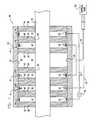
Fig. 1 is schematic, cross-sectional illustration of an electrode cuff for applying current to a nerve, in accordance with respective embodiments of the present invention;Fig. 2 is a schematic, cross-sectional illustration of another electrode cuff for applying current to a nerve;Figs. 3 and 4 are graphs modeling calculated activation functions, respectively, when current is applied using electrode cuffs similar to those shown inFigs. 1 and2 , respectively;Fig. 5 is a schematic, longitudinal cross-sectional view of another electrode cuff for applying current to a nerve; andFig 6 is a schematic, cross-sectional illustration of yet another electrode cuff for applying current to a nerve.Fig. 1 is a schematic, cross-sectional illustration of anelectrode cuff 20 for applying current to anerve 30, in accordance with an embodiment of the present invention.Electrode cuff 20 comprises ahousing 32 which defines an outer surface of the cuff when the cuff is placed at least partially aroundnerve 30.Housing 32 typically comprises an elastic, electrically-insulating material such as silicone or polyurethane, which may have, for example, a Shore A of between about 35 and about 70, such as about 40.Electrode cuff 20 further comprises a plurality of insulatingelements 34 that are arranged at respective positions along the housing, and are typically fixed to aninner surface 37 ofhousing 32 that facesnerve 30 when the electrode cuff is placed at least partially around the nerve. Insulatingelements 34 typically comprise an elastic, electrically-insulating material such as silicone or silicone copolymer, which, for some applications, is softer than that ofhousing 32, for example, a Shore A of between about 10 and about 30, such as about 10.Electrode cuff 20 is typically configured such that, after placement of the cuff on the nerve, respective contact surfaces 36 of insulatingelements 34 at least partially come in physical contact with the nerve, or substantially in physical contact with the nerve, e.g., are less than about 0.5 mm from the surface of the nerve. For some applications, a length that at least one of insulatingelements 34 protrudes fromhousing 32 towardnerve 30 is at least 0.5 mm, such as at least 1 mm. For some applications, insulatingelements 34 andhousing 32 are constructed as separate elements that are coupled to one another, while for other applications, the insulating elements and housing are constructed as a single integrated element that is shaped to define the insulating elements and housing.- Insulating
elements 34 typically comprise one or more (such as exactly two)end insulating elements 38 arranged at or near respective ends of the cuff, and two or more internalinsulating elements 40 arranged at respective positions along the cuff between the end insulating elements.End insulating elements 38 extend alongnerve 30 in order to electrically isolate a portion of the nerve withinelectrode cuff 20 from a portion of the nerve outside the electrode cuff. Inner surface 37 ofhousing 32 and pairs of insulatingelements 34 define arespective cavities 41 along the housing. (It is noted that some pairs of the insulating elements may not define a cavity, such as if two or more of the insulating elements are arranged in contact with one another.)Electrode cuff 20 comprises a plurality ofelectrodes 42, fixed withinhousing 32 inrespective cavities 41 defined by respectivepairs insulating elements 34 andinner surface 37 ofhousing 32. At least one ofcavities 41 defined by a pair of the insulating elements does not have an electrode positioned therein. For example, in the embodiment shown inFig. 1 , the insulating elements define sixcavities 41, a fourth one 43 of which (counting from the left in the figure) does not have an electrode positioned therein. For some applications, at least two, such as least three, of the cavities do not have electrodes positioned therein.Electrodes 42 are typically fixed toinner surface 37 ofhousing 32.- For some applications, at least one of the empty cavities has a length along the cuff of at least 0.5 mm, such as at least 0.7 mm, e.g., at least 1.4 mm or at least 2 mm, and/or no more than 5 mm, e.g., no more than 2 mm. For some applications, a length along the cuff of one of the empty cavities is between about 0.5 and about 5 times a length of one of the cavities that has an electrode therein, such as between about 1 and about 2 times the length.
- At least one of the empty cavities is directly adjacent along the cuff to two cavities containing two respective anode electrodes, or to two cavities containing two respective cathode electrodes.
- Providing the empty cavity results in less physical contact between contact surfaces 36 of insulating
elements 34 andnerve 30 for a cuff of a given length, than in a cuff of the same length without such an empty cavity. As a result, providing the empty cavity tends to reduce constriction of the nerve by the cuff, which may reduce side-effects of application of the cuff to the nerve. Providing the empty cavity does not have a material impact on the activation function achieved by the electrode cuff, as described hereinbelow with reference toFigs. 3 and 4 . - Internal
insulating elements 40 are arranged so as to electricallyseparate electrodes 42, and to guide current from one of the electrodes towards the nerve prior to being taken up by another one of the electrodes. Typically (as shown), insulatingelements 34 are closer tonerve 30 than are the electrodes, i.e., the electrodes are recessed within the cavities. Alternatively (not shown), insulatingelements 34 are generally flush with the faces of the electrodes, such that the inner surfaces of insulating elements and the conductive surfaces of the electrode are equidistant from the nerve. Electrodes 42 comprise onecathode electrode 46, oneanode electrode 48 and at least one further cathode electrode or anode electrode.Active electrodes 44 are coupled to an implantable orexternal control unit 50 byleads cathode electrodes 46 inFig. 1 .- In an embodiment of the present invention,
electrode cuff 20 further comprises two or morepassive electrodes 60, fixed withinhousing 32, and a conductingelement 62, typically a wire, which electrically couples the passive electrodes to one another. A "passive electrode," as used in the present application including the claims, is an electrode that is electrically "device-coupled" to neither (a) any circuitry that is electrically device-coupled to any of the cathode electrodes or anode electrodes, nor (b) an energy source. "Device-coupled" means coupled, directly or indirectly, by components of a device, and excludes coupling via tissue of a subject. (It is noted that the passive electrodes may be passive because of a software-controlled setting of the electrode assembly, and that the software may intermittently change the setting such that these electrodes are not passive.) To "passively electrically couple," as used in the present application including the claims, means to couple using at least one passive electrode and no non-passive electrodes.Passive electrodes 60 and conductingelement 62 create an additional electrical path for the current, such as an additional path for the current that would otherwise leakoutside electrode cuff 20 and travel around the outside of the housing through tissue of the subject. For some applications, conductingelement 62 comprises at least onepassive element 64, such as a resistor, capacitor, and/or inductor. In this embodiment, end insulatingelements 38 help direct any current that leaks fromactive electrodes 44 through the electrical path created bypassive electrodes 60 and conductingelement 62. For some applications,active electrodes 44 are positioned withinhousing 32 longitudinally between the two or more passive electrodes 60 (as shown inFig. 1 ). Alternatively, at least one of the passive electrodes is positioned between the at least one cathode electrode and the at least one anode electrode (configuration not shown). - In an embodiment of the present invention,
electrode cuff 20 comprises one or morepassive electrodes 60 which are not electrically device-coupled to one another. For some applications, the electrode cuff comprises exactly onepassive electrode 60. A separate conducting element, typically a wire, is coupled to each passive electrode at a first end of the conducting element. The second end of the conducting element terminates at a relatively-remote location in the body of the subject that is at a distance of at least 1 cm, e.g., at least 2 or 3 cm, fromelectrode cuff 20. The remote location in the body thus serves as a ground for the passive electrode. For some applications, an electrode is coupled to the remote end of the conducting element, so as to increase electrical contact with tissue at the remote location. - For some applications,
housing 32 has a length of between about 10 and about 14 mm, e.g., about 12.1 mm; an outer radius of between about 4 and about 8 mm, e.g., about 5.9 mm; and an inner radius of between about 3 and about 6 mm, e.g., about 4.5 mm. For some applications, insulatingelements 34 have an outer radius of between about 3 and about 6 mm, e.g., about 4.5 mm (the outer radius of the insulating elements is typically equal to the inner radius of the housing), and an inner radius of between about 2 and about 3.5 mm. For some applications in whichcuff 20 comprises exactly twoend insulating elements 38 and exactly five internalinsulating elements 40, respective edges of insulatingelements 34 are positioned withincuff 32 at the following distances from one end of the cuff: 0.0 mm, between 1.3 and 1.7 mm (e.g., 1.5 mm), between 2.7 and 3.3 mm (e.g., 3.0 mm), between 5.1 and 6.3 mm (e.g., 5.7 mm), between 7.1 and 8.7 mm (e.g., 7.9 mm), between 8.5 and 10.3 mm (e.g., 9.4 mm), and between 10.2 and 12.4 mm (e.g., 11.3 mm), and the insulating elements having the following respective widths: between 0.7 and 0.9 mm (e.g., 0.8 mm), between 0.7 and 0.9 mm (e.g., 0.8 mm), between 1.4 and 1.8 mm (e.g., 1.6 mm), between 0.7 and 0.9 mm (e.g., 0.8 mm), between 0.7 and 0.9 mm (e.g., 0.8 mm), between 1.1 and 1.3 mm (e.g., 1.2 mm), and between 0.7 and 0.9 mm (e.g., 0.8 mm). For some applications,electrodes 42 comprise Pt/Ir. For some applications, as shown inFig. 1 ,electrodes 42 are shaped as rings (e.g.,reference numeral 60 andleftmost reference numeral 42 inFig. 1 refer to a single ring electrode). The rings may have an outer radius that equals, or is slightly greater or less than, the inner radius ofhousing 32. - In an embodiment of the present invention, at least some of the electrodes do not comprise ring electrodes. Instead, each of at least one of
non-empty cavities 41 has fixed therein a plurality of electrodes positioned at least partially circumferentially around a central axis of the cuff. In other words,electrodes 42 arefirst electrodes 42, fixed withinhousing 32 inrespective cavities 41, andcuff 20 comprises at least onesecond electrode 42, fixed withinhousing 32 in one of thecavities 41 in which one of thefirst electrodes 42 is fixed. For some applications, the plurality of electrodes within a single cavity are circumferentially separated from one another by one or more circumferentially arranged insulating elements. - In an embodiment of the present invention, at least one of the one or more of
cavities 41 which are empty in the embodiments described hereinabove, instead has fixed therein one or more electrodes that are not electrically device-coupled (as defined hereinabove) to any elements of the device outside of the cavity. These electrodes thus do not serve the normal function of electrodes in an electrode cuff, i.e., conducting current to and/or from tissue. - In an embodiment of the present invention,
nerve 30 is a vagus nerve, andelectrode cuff 20 is configured to be placed at least partially around the vagus nerve such thatanode electrode 48 is more proximal to the brain than arecathode electrodes 46. Fig. 2 is a schematic, cross-sectional illustration of anelectrode cuff 120 for applying current tonerve 30.Electrode cuff 120 is identical toelectrode cuff 20, described hereinabove with reference toFig. 1 , except thatcuff 120 lackscavity 43 ofcuff 20, which, as mentioned above, does not have one ofelectrodes 42 positioned therein. Instead of the two internalinsulating elements 40 that definecavity 43 incuff 20,cuff 120 has a single, elongated insulatingelement 130, having a length along the housing equal to the sum of the lengths along the cuff ofcavity 43 and the two internalinsulating elements 40 that definecavity 43 incuff 20.- Reference is made to
Figs. 3 and 4 , which are graphs modeling calculated activation functions 200 and 202, respectively, when current is applied using electrode cuffs similar to those shown inFigs. 1 and2 , respectively. These activation functions model myelinated nerve fibers having a diameter of 1 micrometer, over a portion of the length ofnerve 30, at a radius of 1.2 mm from the axis of the nerve. For the purposes of modeling these activation functions, (a) twocathode electrodes 46 are placed at longitudinal sites on the nerve labeled z = 2.25 mm and z = -1.65 mm, respectively, (b)anode electrode 48 is placed at a longitudinal site z = -4.15 mm, and (c) twopassive electrodes 60 are placed at longitudinal sites z = 4.15 mm and z = -5.65 mm, respectively. All of the electrodes are placed at a radius of R = 2.5 mm from the axis ofnerve 30, which has a radius of 1.35 mm. The cavity of activation function 200 (Fig. 3 ) is at z = 0.4 mm. The inner surfaces of all of the insulating elements (i.e., the surfaces closest to the nerve) are placed at a radius R = 1.5 mm from the axis ofnerve 30. - A comparison of activation functions 200 and 202 shows that the two activation functions are nearly identical, which demonstrates that providing
empty cavity 43 does not have a material impact on the activation function achieved by the electrode cuff. - For some applications,
electrode cuff 20 is configured to selectively stimulate fibers of the nerve having certain diameters, such as by using techniques described in one or more of the patent applications referenced hereinbelow. For example,control unit 50 may drivecathode electrode 46 to apply to nerve 30 a stimulating current, which is capable of inducing action potentials in a first set and a second set of nerve fibers of the nerve, and driveanode electrode 48 to apply to the nerve an inhibiting current, which is capable of inhibiting the induced action potentials traveling in the second set of nerve fibers, the nerve fibers in the second set having generally larger diameters than the nerve fibers in the first set. - For some applications,
electrode cuff 20 is configured to apply unidirectional stimulation to the nerve, such as by using techniques described in one or more of the patent applications referenced hereinbelow. For example,control unit 50 may driveanode electrode 48 to apply an inhibiting current capable of inhibiting device-induced action potentials traveling in a non-therapeutic direction innerve 30. For some applications,electrode cuff 20 comprises primary and secondary anode electrodes, the primary anode electrode located between the secondary anode electrode and the cathode electrode. The secondary anode electrode is typically adapted to apply a current with an amplitude less than about one half an amplitude of a current applied by the primary anode electrode. - Reference is made to
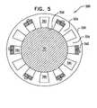
Fig. 5 , which is a schematic, cross-sectional view of anelectrode cuff 320 for applying current tonerve 30.Electrode cuff 320 comprises ahousing 332 which defines an outer surface of the cuff when the cuff is placed at least partially aroundnerve 30.Housing 332 typically comprises an elastic, electrically-insulating material such as silicone or polyurethane, which may have, for example, a Shore A of between about 35 and about 70, such as about 40.Electrode cuff 20 further comprises a plurality ofm insulating elements 334 which are arranged at respective circumferential positions around the housing, and which extend longitudinally along at least a portion of a length of the housing. Insulatingelements 334 typically comprise an elastic, electrically-insulating material such as silicone or silicone copolymer, which, for some applications, is softer than that ofhousing 332, for example, a Shore A of between about 10 and about 30, such as about 10.Electrode cuff 320 is typically configured such that, after placement of the cuff on the nerve, respective contact surfaces 336 of insulatingelements 334 come in physical contact with the nerve, cr substantially in physical contact with the nerve, e.g., are less than about 0.5 mm from the surface of the nerve. For some applications, a length that at least one of insulatingelements 334 protrudes fromhousing 332 toward nerve 330 is at least 0.5 mm, such as at least 1 mm. For some applications, insulatingelements 334 andhousing 332 are constructed as separate elements that are coupled to one another, while for other applications, the insulating elements and housing are constructed as a single integrated element that is shaped to define the insulating elements and housing. - Together, insulating
elements 334 define a plurality ofn cavities 341 aroundhousing 332, wherein n is less than or equal to m (the number of insulating elements, as mentioned above). Typically, n equals m. Alternatively, n is less than m, such as if two or more of the insulating elements are arranged in contact with one another. It is noted that thecavities 341 ofelectrode cuff 320 are oriented in a direction that is generally perpendicular to that ofcavities 41 ofelectrode cuff 20 ofFig. 1 . Insulatingelements 334 ofelectrode cuff 320 run along the nerve in a direction parallel with a longitudinal axis of the nerve, while insulatingelements 34 ofelectrode cuff 20 surround all or a portion of the nerve. Electrode cuff 320 comprises a plurality ofp electrodes 342, fixed withinhousing 332 inrespective cavities 341 defined by two of insulatingelements 334, wherein p is less than n. In other words, at least one ofcavities 341 defined by a pair of the insulating elements does not have an electrode positioned therein. For example, in the embodiment shown inFig. 5 , the insulating elements define twelvecavities 341, half of which do not have an electrode positioned therein. For some applications, p equals a fraction of n, such as 2/3, 1/2, 1/3, or 1/4.- For some applications,
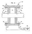
electrode cuff 320 comprises elements described hereinabove with reference toFig. 1 , such active and/or passive electrodes, and/or a control unit coupled to the cuff with leads. Fig. 6 is a schematic, cross-sectional illustration of anelectrode cuff 420 for applying current tonerve 30.Electrode cuff 420 comprises a housing 432 which defines an outer surface of the cuff when the cuff is placed at least partially aroundnerve 30. Housing 432 typically comprises an elastic, electrically-insulating material such as silicone or polyurethane, which may have, for example, a Shore A of between about 35 and about 70, such as about 40.Electrode cuff 420 further comprises at least two, e.g., exactly two, insulatingelements 434 that are arranged at respective positions along the housing, and are typically fixed to aninner surface 437 of the housing that facesnerve 30 when the cuff is placed at least partially around the nerve. Insulatingelements 434 typically comprise an elastic, electrically-insulating material such as silicone or silicone copolymer, which, for some applications, is softer than that of housing 432, for example, a Shore A of between about 10 and about 30, such as about 10.Electrode cuff 420 is typically configured such that, after placement of the cuff on the nerve, respective contact surfaces 436 of insulatingelements 434 come in physical contact with the nerve, or substantially in physical contact with the nerve, e.g., are less than about 0.5 mm from the surface of the nerve. For some applications, a length that at least one of insulatingelements 434 protrudes from housing 432 towardnerve 30 is at least 0.5 mm, such as at least 1 mm. For some applications, insulatingelements 434 and housing 432 are constructed as separate elements that are coupled to one another, while for other applications, the insulating elements and housing are constructed as a single integrated element that is shaped to define the insulating elements and housing. Insulatingelements 434 extend alongnerve 30 in order to electrically isolate a portion of the nerve withinelectrode cuff 420 from a portion of the nerve outside the electrode cuff.- Insulating
elements 434 are positioned along housing 432 such thatend portions 456 of housing 432 extend beyond the insulating elements toward respectivelongitudinal ends 458 of the housing. In other words, the insulating elements are longitudinally recessed from ends 458 of the housing. In addition, insulatingelements 434 are positioned along housing 432 such thatinner surface 437 of housing 432 and one or more pairs of the insulating elements define one or morerespective cavities 441 along the housing. In the exemplary configuration shown inFig. 6 , the inner surface of the housing and exactly one pair of the insulating elements define exactly one cavity. Cuff 420 comprises at least twoelectrodes 442, each of which is fixed toinner surface 437 of housing 432 at at least a portion of one ofend portions 456 of housing 432. At least one ofcavities 441, e.g., all ofcavities 441 and/or exactly one of the cavities, does not have an electrode positioned therein. In other words, the electrodes are fixed to the housing in fewer than all of the cavities, e.g., in none of the cavities. For some applications, at least one of the empty cavities has a length along the cuff of at least 0.5 mm, such as at least 0.7 mm, e.g., at least 1.4 mm or at least 2 mm, and/or no more than 5 mm, e.g., no more than 3 mm or no more than 3 cm.- Providing the empty cavity results in less physical contact between
contact surfaces 436 of insulatingelements 434 andnerve 30 for a cuff of a given length, than in a cuff of the same length without such an empty cavity. As a result, providing the empty cavity tends to reduce constriction of the nerve by the cuff, which may reduce side-effects of application of the cuff to the nerve. Providing the empty cavity does not have a material impact on the activation function achieved by the electrode cuff. Electrodes 442 comprise at least one active, i.e., stimulating and/or sensing, electrode, such as at least onecathode electrode 446 and at least oneanode electrode 448. The active electrodes are coupled to an implantable orexternal control unit 450 byleads cathode electrodes 46 inFig. 1 . For some applications,cuff 420 comprises one or more passive electrodes, as described hereinabove with reference toFig. 1 .- In an embodiment of the present invention, at least some of
electrodes 442 comprise ring electrodes. Alternatively, the electrodes do not comprise ring electrodes. Instead, fixed to at least a portion of each of end portions are a plurality of electrodes positioned at least partially circumferentially around a central axis of the cuff. In other words,electrodes 442 arefirst electrodes 442, andcuff 420 comprises at least onesecond electrode 442. For some applications, the plurality of electrodes are circumferentially separated from one another by one or more circumferentially arranged insulating elements. - In an alternative arrangement, at least one of the one or more of
cavities 441 which are empty in the arrangement described hereinabove, instead has fixed therein one or more electrodes that are not electrically device-coupled (as defined hereinabove) to any elements of the device outside of the cavity. These electrodes thus do not serve the normal function of electrodes in an electrode cuff, i.e., conducting current to and/or from tissue. - In an alternative arrangement, insulating
elements 434 are not positioned so as to define anycavities 441. For example, insulatingelements 434 may comprise exactly one insulating element, which may have a length of at least 0.5 mm, such as at least 1 mm. - It is noted that although electrode cuffs 20, 320 and 420 and their elements are generally shown in the figures and described herein in a cylindrical configuration, other geometrical configurations, such as non-rotationally symmetric configurations, are also suitable for applying the principles of the present invention. In particular,
housings electrode cuff housing 32 surrounds the electrodes. - Techniques described herein can be practiced in combination with techniques described with reference to
Figs. 2 ,3 , and/or 6 ofUS Patent Application 11/280,884 to Ayal et al., filed November 15, 2005 US Patent Application Publication 2006/0106441 , and which is assigned to the assignee of the present application. For example: - for some applications, a closest distance between cathode electrodes 46 (i.e., the distance between the respective cathode electrodes' edges that are closest to one another) is equal to at least a radius R of
nerve 30, e.g., at least 1.5 times the radius of the nerve, as described with reference toFig. 2 of the '441 publication; and/or - for some applications, end insulating
elements 38 are elongated, as described with reference toFig. 6 of the '441 publication. - As used in the present patent application, including in the claims, "longitudinal" means along the length of, and does not mean "around" or "circumferential." For example, "longitudinal positions" along the housing means positions along the length of the housing, rather than positions arranged circumferentially around a longitudinal axis of the housing or the nerve. Such longitudinal positions might be measured in mm from one end of the housing.
- Techniques and apparatus described in one or more of the following applications can be combined with techniques and apparatus described herein:
US Provisional Patent Application 60/383,157 to Ayal et al., filed May 23, 2002- International Patent Application
PCT / IL02 / 00068 to Cohen et al., filed January 23, 2002 WO 03/018113 A1 US Patent Application 10/488,334US 2004/0243182 A1 , in the national stage thereof, US Patent Application 09/944,913 to Cohen and Gross, filed August 31, 2001 US 2003/0045914 A1 , which issued asUS Patent 6, 684, 105 ,US Patent Application 09/824,682 to Cohen and Ayal, filed April 4, 2001 US 2002/0099419 A1 ,US Patent Application 10/205,475 to Gross et al., filed July 24, 2002US 2003/0045909 A1 ,US Patent Application 10/205,474 to Gross et al., filed July 24, 2002US 2003/0050677 A1 , which issued asUS Patent 6,907,295 ,- International Patent Application
PCT / IL03 / 00431 to Ayal et al., filed May 23, 2003 WO 03/099377 A1 - International Patent Application
PCT / IL03 / 00430 to Ayal et al., filed May 23, 2003 WO 03/099373 A2 US Patent Application 10/529,149US 2006/0116739 A1 , in the national stage thereof, US Patent Application 10/719,659 to Ben David et al., filed November 20, 2003US 2004/0193231 A1 ,US Patent Application 11/022,011 to Cohen et al., filed December 22, 2004 US 2006/0136024 A1 ,US Patent Application 11/234,877 to Ben-David et al., filed September 22, 2005 US 2006/0100668 A1 , andUS Patent Application 11/280,884 to Ayal et al., filed November 15, 2005 US Patent Application Publication 2006/0106441 .


Claims (11)
- Apparatus for application to a nerve (30) of a subject, comprising:an electrode cuff (20), which comprises:a housing (32), configured to be placed at least partially around the nerve (30) so as to define an inner surface (37) of the housing (32) that faces the nerve (30) ; anda plurality of insulating elements (34) coupled to the inner surface (37) of the housing (32) at respective insulating element longitudinal positions along the housing (32), such that the inner surface (37) of the housing (32) and pairs of the insulating elements (34) define a plurality of respective cavities (41) at respective cavity longitudinal positions along the housing (32);the apparatus further comprising:a plurality of electrodes (42), which comprise one cathode electrode (46), one anode electrode (4B) and at least one further cathode electrode (46) or anode electrode (48), the electrodes (42) of said plurality of electrodes being fixed to the housing, anda control unit (50), coupled to the electrodes (42), and configured to drive at least a portion of the electrodes (42) to apply a current to the nerve (30);whereinat least one of the cavities (41) is an empty cavity (43) that does not have an electrode positioned therein, and wherein the apparatus ischaracterized in that:the empty cavity (43) is between and directly adjacent along the cuff (20) to two cavities (41) containing two respective anode electrodes (48), or two cavities (41) containing two respective cathode electrodes (46).
- The apparatus according to claim 1, wherein the insulating elements (34) are shaped so as to define respective contact surfaces (36), and wherein the housing (32) and the insulating elements (34) are configured such that the contact surfaces (36) are suitable for being positioned less than 0.5 mm from a surface of the nerve (30) when the housing (32) is placed at least partially around the nerve (3C).
- The apparatus according to claim 1, wherein the insulating elements (34) are shaped so as to define respective contact surfaces (36), and wherein the housing (32) and the insulating elements (34) are configured such that the contact surfaces (36) are suitable for at least partially coming in physical contact with the nerve (30) when the housing (32) is placed at least partially around the nerve (30).
- The apparatus according to claim 1, wherein the electrodes (42) are fixed to the housing (32) in a number of the cavities (41), wherein a difference between the number of the cavities (41) and a total number of the cavities (41, 43) is an integer between 1 and 3, inclusive, such that between 1 and 3 of the cavities (43) do not have any of the electrodes (42) fixed therein.
- The apparatus according to claim 1,
wherein the housing (32) has a length of between 10 mm and 14 mm, an outer radius of between 4 mm and 8 mm, an inner radius of between 3 mm and 6 mm,
wherein the insulating elements (34) have an outer radius of between 3 mm and 6 mm, and an inner radius of between 2 mm and 3.5 mm, and
wherein the plurality of insulating elements (34) comprises exactly seven insulating elements (34), respective edges of which are positioned within the housing (32) at the following respective distances from one end of the housing (32): 0.0 mm, between 1.3 and 1.7 mm, between 2.7 and 3.3 mm, between 5.1 and 6.3 mm, between 7.1 and 8.7 mm, between 8.5 and 10.3 mm, and between 10.2 and 12.4 mm, and the insulating elements (34) having the following respective widths: between 0.7 and 0.9 mm, between 0.7 and 0.9 mm, between 1.4 and 1.8 mm, between 0.7 and 0.9 mm, between C.7 and 0.9 mm, between 1.1 and 1.3 mm, and between C.7 and 0.9 mm. - The apparatus according to claim 1, wherein the electrodes (42) comprise ring electrodes.
- The apparatus according to claim 1, wherein the one or more cavities (42) include at least four cavities (42), and wherein the electrodes (42) are fixed to the housing (32) in at least three of the cavities (41).
- The apparatus according to claim 1, wherein the apparatus further comprises two or more passive electrodes (60), and wherein the apparatus further comprises a conducting element (62), which electrically couples the passive electrodes (60) to one another.
- The apparatus according to claim 8,
wherein the plurality of insulating elements (34) includes at least seven insulating elements (34), which are arranged along the housing (32) such that the inner surface of the housing (32) and the pairs of insulating elements (34) define first, second, third, fourth, fifth, and sixth cavities, the first cavity closest to an end of the housing (32), the second adjacent to the first, the third adjacent to the second, the fourth adjacent to the third, the fifth adjacent to the fourth, and the sixth adjacent to the fifth,
wherein the at least one cathode electrode (46) comprises at least one first cathode electrode (46) and at least one second cathode electrode (46),
wherein at least a first one of the passive electrodes (60) is fixed to the housing (32) in the first cavity,
wherein the at least one anode electrode (48) is fixed to the housing (32) in the second cavity,
wherein the at least one first cathode electrode (46) is fixed to the housing (32) in the third cavity,
wherein no electrodes are fixed to the housing (32) in the fourth cavity (43),
wherein the at least one second cathode electrode (46) is fixed to the housing (32) in the fifth cavity, and
wherein at least a second one of the passive electrodes (60) is fixed to the housing (32) in the sixth cavity. - The apparatus according to claim 1, wherein a length that at least one of the insulating elements (34) protrudes from the housing (32) toward the nerve (30) when the housing (32) is placed at least partially around the nerve (30) is at least 0.5 mm.
- The apparatus according to claim 1, wherein at least two of the electrodes (42) are fixed to the housing (32) in one of the cavities 41).
Applications Claiming Priority (1)
| Application Number | Priority Date | Filing Date | Title |
|---|---|---|---|
| US12/217,930US20100010603A1 (en) | 2008-07-09 | 2008-07-09 | Electrode cuffs |
Publications (2)
| Publication Number | Publication Date |
|---|---|
| EP2143465A1 EP2143465A1 (en) | 2010-01-13 |
| EP2143465B1true EP2143465B1 (en) | 2012-10-03 |
Family
ID=40969406
Family Applications (1)
| Application Number | Title | Priority Date | Filing Date |
|---|---|---|---|
| EP09251749ANot-in-forceEP2143465B1 (en) | 2008-07-09 | 2009-07-07 | Electrode cuffs |
Country Status (2)
| Country | Link |
|---|---|
| US (1) | US20100010603A1 (en) |
| EP (1) | EP2143465B1 (en) |
Cited By (15)
| Publication number | Priority date | Publication date | Assignee | Title |
|---|---|---|---|---|
| US9643022B2 (en) | 2013-06-17 | 2017-05-09 | Nyxoah SA | Flexible control housing for disposable patch |
| US9849289B2 (en) | 2009-10-20 | 2017-12-26 | Nyxoah SA | Device and method for snoring detection and control |
| US9855032B2 (en) | 2012-07-26 | 2018-01-02 | Nyxoah SA | Transcutaneous power conveyance device |
| US9943686B2 (en) | 2009-10-20 | 2018-04-17 | Nyxoah SA | Method and device for treating sleep apnea based on tongue movement |
| US9956393B2 (en) | 2015-02-24 | 2018-05-01 | Elira, Inc. | Systems for increasing a delay in the gastric emptying time for a patient using a transcutaneous electro-dermal patch |
| US10052097B2 (en) | 2012-07-26 | 2018-08-21 | Nyxoah SA | Implant unit delivery tool |
| US10118035B2 (en) | 2015-02-24 | 2018-11-06 | Elira, Inc. | Systems and methods for enabling appetite modulation and/or improving dietary compliance using an electro-dermal patch |
| US10335302B2 (en) | 2015-02-24 | 2019-07-02 | Elira, Inc. | Systems and methods for using transcutaneous electrical stimulation to enable dietary interventions |
| US10376145B2 (en) | 2015-02-24 | 2019-08-13 | Elira, Inc. | Systems and methods for enabling a patient to achieve a weight loss objective using an electrical dermal patch |
| US10751537B2 (en) | 2009-10-20 | 2020-08-25 | Nyxoah SA | Arced implant unit for modulation of nerves |
| US10765863B2 (en) | 2015-02-24 | 2020-09-08 | Elira, Inc. | Systems and methods for using a transcutaneous electrical stimulation device to deliver titrated therapy |
| US10814137B2 (en) | 2012-07-26 | 2020-10-27 | Nyxoah SA | Transcutaneous power conveyance device |
| US10864367B2 (en) | 2015-02-24 | 2020-12-15 | Elira, Inc. | Methods for using an electrical dermal patch in a manner that reduces adverse patient reactions |
| US11253712B2 (en) | 2012-07-26 | 2022-02-22 | Nyxoah SA | Sleep disordered breathing treatment apparatus |
| US11957895B2 (en) | 2015-02-24 | 2024-04-16 | Elira, Inc. | Glucose-based modulation of electrical stimulation to enable weight loss |
Families Citing this family (59)
| Publication number | Priority date | Publication date | Assignee | Title |
|---|---|---|---|---|
| US6907295B2 (en) | 2001-08-31 | 2005-06-14 | Biocontrol Medical Ltd. | Electrode assembly for nerve control |
| US8565896B2 (en) | 2010-11-22 | 2013-10-22 | Bio Control Medical (B.C.M.) Ltd. | Electrode cuff with recesses |
| US7904176B2 (en) | 2006-09-07 | 2011-03-08 | Bio Control Medical (B.C.M.) Ltd. | Techniques for reducing pain associated with nerve stimulation |
| US8571653B2 (en)* | 2001-08-31 | 2013-10-29 | Bio Control Medical (B.C.M.) Ltd. | Nerve stimulation techniques |
| US8880192B2 (en) | 2012-04-02 | 2014-11-04 | Bio Control Medical (B.C.M.) Ltd. | Electrode cuffs |
| US8718791B2 (en) | 2003-05-23 | 2014-05-06 | Bio Control Medical (B.C.M.) Ltd. | Electrode cuffs |
| US10912712B2 (en) | 2004-03-25 | 2021-02-09 | The Feinstein Institutes For Medical Research | Treatment of bleeding by non-invasive stimulation |
| US11207518B2 (en)* | 2004-12-27 | 2021-12-28 | The Feinstein Institutes For Medical Research | Treating inflammatory disorders by stimulation of the cholinergic anti-inflammatory pathway |
| WO2009029614A1 (en)* | 2007-08-27 | 2009-03-05 | The Feinstein Institute For Medical Research | Devices and methods for inhibiting granulocyte activation by neural stimulation |
| WO2009146030A1 (en)* | 2008-03-31 | 2009-12-03 | The Feinstein Institute For Medical Research | Methods and systems for reducing inflammation by neuromodulation of t-cell activity |
| US9662490B2 (en) | 2008-03-31 | 2017-05-30 | The Feinstein Institute For Medical Research | Methods and systems for reducing inflammation by neuromodulation and administration of an anti-inflammatory drug |
| EP2355893B1 (en)* | 2008-11-18 | 2013-12-25 | Setpoint Medical Corporation | Devices for optimizing electrode placement for anti-inflamatory stimulation |
| US9211410B2 (en) | 2009-05-01 | 2015-12-15 | Setpoint Medical Corporation | Extremely low duty-cycle activation of the cholinergic anti-inflammatory pathway to treat chronic inflammation |
| US8996116B2 (en)* | 2009-10-30 | 2015-03-31 | Setpoint Medical Corporation | Modulation of the cholinergic anti-inflammatory pathway to treat pain or addiction |
| WO2010144578A2 (en) | 2009-06-09 | 2010-12-16 | Setpoint Medical Corporation | Nerve cuff with pocket for leadless stimulator |
| WO2014169145A1 (en) | 2013-04-10 | 2014-10-16 | Setpoint Medical Corporation | Closed-loop vagus nerve stimulation |
| US9833621B2 (en) | 2011-09-23 | 2017-12-05 | Setpoint Medical Corporation | Modulation of sirtuins by vagus nerve stimulation |
| EP2515996B1 (en) | 2009-12-23 | 2019-09-18 | Setpoint Medical Corporation | Neural stimulation devices and systems for treatment of chronic inflammation |
| US12172017B2 (en) | 2011-05-09 | 2024-12-24 | Setpoint Medical Corporation | Vagus nerve stimulation to treat neurodegenerative disorders |
| WO2012154865A2 (en) | 2011-05-09 | 2012-11-15 | Setpoint Medical Corporation | Single-pulse activation of the cholinergic anti-inflammatory pathway to treat chronic inflammation |
| US8934992B2 (en)* | 2011-09-01 | 2015-01-13 | Inspire Medical Systems, Inc. | Nerve cuff |
| US8918190B2 (en) | 2011-12-07 | 2014-12-23 | Cyberonics, Inc. | Implantable device for evaluating autonomic cardiovascular drive in a patient suffering from chronic cardiac dysfunction |
| US8630709B2 (en) | 2011-12-07 | 2014-01-14 | Cyberonics, Inc. | Computer-implemented system and method for selecting therapy profiles of electrical stimulation of cervical vagus nerves for treatment of chronic cardiac dysfunction |
| US8577458B1 (en) | 2011-12-07 | 2013-11-05 | Cyberonics, Inc. | Implantable device for providing electrical stimulation of cervical vagus nerves for treatment of chronic cardiac dysfunction with leadless heart rate monitoring |
| US8600505B2 (en) | 2011-12-07 | 2013-12-03 | Cyberonics, Inc. | Implantable device for facilitating control of electrical stimulation of cervical vagus nerves for treatment of chronic cardiac dysfunction |
| US10188856B1 (en) | 2011-12-07 | 2019-01-29 | Cyberonics, Inc. | Implantable device for providing electrical stimulation of cervical vagus nerves for treatment of chronic cardiac dysfunction |
| US8918191B2 (en) | 2011-12-07 | 2014-12-23 | Cyberonics, Inc. | Implantable device for providing electrical stimulation of cervical vagus nerves for treatment of chronic cardiac dysfunction with bounded titration |
| US8700150B2 (en) | 2012-01-17 | 2014-04-15 | Cyberonics, Inc. | Implantable neurostimulator for providing electrical stimulation of cervical vagus nerves for treatment of chronic cardiac dysfunction with bounded titration |
| US8571654B2 (en) | 2012-01-17 | 2013-10-29 | Cyberonics, Inc. | Vagus nerve neurostimulator with multiple patient-selectable modes for treating chronic cardiac dysfunction |
| US9572983B2 (en) | 2012-03-26 | 2017-02-21 | Setpoint Medical Corporation | Devices and methods for modulation of bone erosion |
| CN104582787A (en)* | 2012-04-02 | 2015-04-29 | 生物控制医疗(Bcm)有限公司 | Electrode cuffs |
| US8688212B2 (en) | 2012-07-20 | 2014-04-01 | Cyberonics, Inc. | Implantable neurostimulator-implemented method for managing bradycardia through vagus nerve stimulation |
| US8923964B2 (en) | 2012-11-09 | 2014-12-30 | Cyberonics, Inc. | Implantable neurostimulator-implemented method for enhancing heart failure patient awakening through vagus nerve stimulation |
| US9452290B2 (en) | 2012-11-09 | 2016-09-27 | Cyberonics, Inc. | Implantable neurostimulator-implemented method for managing tachyarrhythmia through vagus nerve stimulation |
| US9643008B2 (en) | 2012-11-09 | 2017-05-09 | Cyberonics, Inc. | Implantable neurostimulator-implemented method for enhancing post-exercise recovery through vagus nerve stimulation |
| US9643011B2 (en) | 2013-03-14 | 2017-05-09 | Cyberonics, Inc. | Implantable neurostimulator-implemented method for managing tachyarrhythmic risk during sleep through vagus nerve stimulation |
| US9999773B2 (en) | 2013-10-30 | 2018-06-19 | Cyberonics, Inc. | Implantable neurostimulator-implemented method utilizing multi-modal stimulation parameters |
| US9511228B2 (en) | 2014-01-14 | 2016-12-06 | Cyberonics, Inc. | Implantable neurostimulator-implemented method for managing hypertension through renal denervation and vagus nerve stimulation |
| US9272143B2 (en) | 2014-05-07 | 2016-03-01 | Cyberonics, Inc. | Responsive neurostimulation for the treatment of chronic cardiac dysfunction |
| US9713719B2 (en) | 2014-04-17 | 2017-07-25 | Cyberonics, Inc. | Fine resolution identification of a neural fulcrum for the treatment of chronic cardiac dysfunction |
| US9409024B2 (en) | 2014-03-25 | 2016-08-09 | Cyberonics, Inc. | Neurostimulation in a neural fulcrum zone for the treatment of chronic cardiac dysfunction |
| US9415224B2 (en) | 2014-04-25 | 2016-08-16 | Cyberonics, Inc. | Neurostimulation and recording of physiological response for the treatment of chronic cardiac dysfunction |
| US9950169B2 (en) | 2014-04-25 | 2018-04-24 | Cyberonics, Inc. | Dynamic stimulation adjustment for identification of a neural fulcrum |
| US9737716B2 (en) | 2014-08-12 | 2017-08-22 | Cyberonics, Inc. | Vagus nerve and carotid baroreceptor stimulation system |
| US9533153B2 (en) | 2014-08-12 | 2017-01-03 | Cyberonics, Inc. | Neurostimulation titration process |
| US9770599B2 (en) | 2014-08-12 | 2017-09-26 | Cyberonics, Inc. | Vagus nerve stimulation and subcutaneous defibrillation system |
| US11311725B2 (en) | 2014-10-24 | 2022-04-26 | Setpoint Medical Corporation | Systems and methods for stimulating and/or monitoring loci in the brain to treat inflammation and to enhance vagus nerve stimulation |
| US9504832B2 (en) | 2014-11-12 | 2016-11-29 | Cyberonics, Inc. | Neurostimulation titration process via adaptive parametric modification |
| US11406833B2 (en) | 2015-02-03 | 2022-08-09 | Setpoint Medical Corporation | Apparatus and method for reminding, prompting, or alerting a patient with an implanted stimulator |
| US10596367B2 (en) | 2016-01-13 | 2020-03-24 | Setpoint Medical Corporation | Systems and methods for establishing a nerve block |
| CN108882885A (en) | 2016-01-20 | 2018-11-23 | 赛博恩特医疗器械公司 | Control of vagus nerve stimulation |
| US11471681B2 (en) | 2016-01-20 | 2022-10-18 | Setpoint Medical Corporation | Batteryless implantable microstimulators |
| EP3405255A4 (en) | 2016-01-20 | 2019-10-16 | Setpoint Medical Corporation | IMPLANTABLE MICROSTIMULATORS AND INDUCTION RECHARGE SYSTEMS |
| US10583304B2 (en) | 2016-01-25 | 2020-03-10 | Setpoint Medical Corporation | Implantable neurostimulator having power control and thermal regulation and methods of use |
| EP3664889B1 (en) | 2017-08-11 | 2024-02-21 | Inspire Medical Systems, Inc. | Cuff electrode |
| US11173307B2 (en) | 2017-08-14 | 2021-11-16 | Setpoint Medical Corporation | Vagus nerve stimulation pre-screening test |
| US11260229B2 (en) | 2018-09-25 | 2022-03-01 | The Feinstein Institutes For Medical Research | Methods and apparatuses for reducing bleeding via coordinated trigeminal and vagal nerve stimulation |
| WO2020210786A1 (en) | 2019-04-12 | 2020-10-15 | Setpoint Medical Corporation | Vagus nerve stimulation to treat neurodegenerative disorders |
| EP4566539A1 (en) | 2020-05-21 | 2025-06-11 | The Feinstein Institutes for Medical Research | Systems and methods for vagus nerve stimulation |
Family Cites Families (26)
| Publication number | Priority date | Publication date | Assignee | Title |
|---|---|---|---|---|
| US2201104A (en) | 1938-11-21 | 1940-05-14 | Samuel H Davis | Paste brush holder |
| US4535785A (en) | 1982-09-23 | 1985-08-20 | Minnesota Mining And Manufacturing Co. | Method and apparatus for determining the viability and survival of sensori-neutral elements within the inner ear |
| US4573481A (en) | 1984-06-25 | 1986-03-04 | Huntington Institute Of Applied Research | Implantable electrode array |
| US4628942A (en) | 1984-10-11 | 1986-12-16 | Case Western Reserve University | Asymmetric shielded two electrode cuff |
| US4602624A (en) | 1984-10-11 | 1986-07-29 | Case Western Reserve University | Implantable cuff, method of manufacture, and method of installation |
| US4649936A (en) | 1984-10-11 | 1987-03-17 | Case Western Reserve University | Asymmetric single electrode cuff for generation of unidirectionally propagating action potentials for collision blocking |
| US4608985A (en) | 1984-10-11 | 1986-09-02 | Case Western Reserve University | Antidromic pulse generating wave form for collision blocking |
| US5095905A (en) | 1990-06-07 | 1992-03-17 | Medtronic, Inc. | Implantable neural electrode |
| US5199430A (en) | 1991-03-11 | 1993-04-06 | Case Western Reserve University | Micturitional assist device |
| US5215086A (en) | 1991-05-03 | 1993-06-01 | Cyberonics, Inc. | Therapeutic treatment of migraine symptoms by stimulation |
| IT1260485B (en) | 1992-05-29 | 1996-04-09 | PROCEDURE AND DEVICE FOR THE TREATMENT OF THE OBESITY OF A PATIENT | |
| US5400784A (en) | 1993-10-15 | 1995-03-28 | Case Western Reserve University | Slowly penetrating inter-fascicular nerve cuff electrode and method of using |
| US5487756A (en) | 1994-12-23 | 1996-01-30 | Simon Fraser University | Implantable cuff having improved closure |
| US5755750A (en) | 1995-11-13 | 1998-05-26 | University Of Florida | Method and apparatus for selectively inhibiting activity in nerve fibers |
| DE19609471A1 (en) | 1996-03-01 | 1997-11-13 | Biotronik Mess & Therapieg | Electrode arrangement |
| US5833664A (en)* | 1996-10-08 | 1998-11-10 | Seare, Jr.; William J. | Noded cuffs for transcutaneous or intrabody prosthetic devices |
| US5824027A (en) | 1997-08-14 | 1998-10-20 | Simon Fraser University | Nerve cuff having one or more isolated chambers |
| US6341236B1 (en) | 1999-04-30 | 2002-01-22 | Ivan Osorio | Vagal nerve stimulation techniques for treatment of epileptic seizures |
| AU6465400A (en) | 1999-08-04 | 2001-03-05 | Impulse Dynamics N.V. | Inhibition of action potentials |
| US6456866B1 (en) | 1999-09-28 | 2002-09-24 | Dustin Tyler | Flat interface nerve electrode and a method for use |
| US6684105B2 (en) | 2001-08-31 | 2004-01-27 | Biocontrol Medical, Ltd. | Treatment of disorders by unidirectional nerve stimulation |
| US6907295B2 (en) | 2001-08-31 | 2005-06-14 | Biocontrol Medical Ltd. | Electrode assembly for nerve control |
| US6600956B2 (en) | 2001-08-21 | 2003-07-29 | Cyberonics, Inc. | Circumneural electrode assembly |
| US7627384B2 (en) | 2004-11-15 | 2009-12-01 | Bio Control Medical (B.C.M.) Ltd. | Techniques for nerve stimulation |
| US8116881B2 (en)* | 2004-06-10 | 2012-02-14 | Bio Control Medical (B.C.M.) Ltd | Electrode assembly for nerve control |
| US7761168B2 (en)* | 2006-07-13 | 2010-07-20 | Yossi Gross | Peltier unidirectional and selective nerve stimulation |
- 2008
- 2008-07-09USUS12/217,930patent/US20100010603A1/ennot_activeAbandoned
- 2009
- 2009-07-07EPEP09251749Apatent/EP2143465B1/ennot_activeNot-in-force
Cited By (29)
| Publication number | Priority date | Publication date | Assignee | Title |
|---|---|---|---|---|
| US10716940B2 (en) | 2009-10-20 | 2020-07-21 | Nyxoah SA | Implant unit for modulation of small diameter nerves |
| US9849289B2 (en) | 2009-10-20 | 2017-12-26 | Nyxoah SA | Device and method for snoring detection and control |
| US11857791B2 (en) | 2009-10-20 | 2024-01-02 | Nyxoah SA | Arced implant unit for modulation of nerves |
| US9943686B2 (en) | 2009-10-20 | 2018-04-17 | Nyxoah SA | Method and device for treating sleep apnea based on tongue movement |
| US9950166B2 (en) | 2009-10-20 | 2018-04-24 | Nyxoah SA | Acred implant unit for modulation of nerves |
| US11273307B2 (en) | 2009-10-20 | 2022-03-15 | Nyxoah SA | Method and device for treating sleep apnea |
| US10898717B2 (en) | 2009-10-20 | 2021-01-26 | Nyxoah SA | Device and method for snoring detection and control |
| US10751537B2 (en) | 2009-10-20 | 2020-08-25 | Nyxoah SA | Arced implant unit for modulation of nerves |
| US11253712B2 (en) | 2012-07-26 | 2022-02-22 | Nyxoah SA | Sleep disordered breathing treatment apparatus |
| US10814137B2 (en) | 2012-07-26 | 2020-10-27 | Nyxoah SA | Transcutaneous power conveyance device |
| US9855032B2 (en) | 2012-07-26 | 2018-01-02 | Nyxoah SA | Transcutaneous power conveyance device |
| US11730469B2 (en) | 2012-07-26 | 2023-08-22 | Nyxoah SA | Implant unit delivery tool |
| US10918376B2 (en) | 2012-07-26 | 2021-02-16 | Nyxoah SA | Therapy protocol activation triggered based on initial coupling |
| US10716560B2 (en) | 2012-07-26 | 2020-07-21 | Nyxoah SA | Implant unit delivery tool |
| US10052097B2 (en) | 2012-07-26 | 2018-08-21 | Nyxoah SA | Implant unit delivery tool |
| US11642534B2 (en) | 2013-06-17 | 2023-05-09 | Nyxoah SA | Programmable external control unit |
| US9643022B2 (en) | 2013-06-17 | 2017-05-09 | Nyxoah SA | Flexible control housing for disposable patch |
| US10512782B2 (en) | 2013-06-17 | 2019-12-24 | Nyxoah SA | Remote monitoring and updating of a medical device control unit |
| US11298549B2 (en) | 2013-06-17 | 2022-04-12 | Nyxoah SA | Control housing for disposable patch |
| US9956393B2 (en) | 2015-02-24 | 2018-05-01 | Elira, Inc. | Systems for increasing a delay in the gastric emptying time for a patient using a transcutaneous electro-dermal patch |
| US11197613B2 (en) | 2015-02-24 | 2021-12-14 | Elira, Inc. | Systems and methods for enabling a patient to achieve a weight loss objective using an electrical dermal patch |
| US10143840B2 (en) | 2015-02-24 | 2018-12-04 | Elira, Inc. | Systems and methods for enabling appetite modulation and/or improving dietary compliance using an electro-dermal patch |
| US10765863B2 (en) | 2015-02-24 | 2020-09-08 | Elira, Inc. | Systems and methods for using a transcutaneous electrical stimulation device to deliver titrated therapy |
| US10118035B2 (en) | 2015-02-24 | 2018-11-06 | Elira, Inc. | Systems and methods for enabling appetite modulation and/or improving dietary compliance using an electro-dermal patch |
| US10335302B2 (en) | 2015-02-24 | 2019-07-02 | Elira, Inc. | Systems and methods for using transcutaneous electrical stimulation to enable dietary interventions |
| US11712562B2 (en) | 2015-02-24 | 2023-08-01 | Elira, Inc. | Systems and methods for using a transcutaneous electrical stimulation device to deliver titrated therapy |
| US10864367B2 (en) | 2015-02-24 | 2020-12-15 | Elira, Inc. | Methods for using an electrical dermal patch in a manner that reduces adverse patient reactions |
| US10376145B2 (en) | 2015-02-24 | 2019-08-13 | Elira, Inc. | Systems and methods for enabling a patient to achieve a weight loss objective using an electrical dermal patch |
| US11957895B2 (en) | 2015-02-24 | 2024-04-16 | Elira, Inc. | Glucose-based modulation of electrical stimulation to enable weight loss |
Also Published As
| Publication number | Publication date |
|---|---|
| EP2143465A1 (en) | 2010-01-13 |
| US20100010603A1 (en) | 2010-01-14 |
Similar Documents
| Publication | Publication Date | Title |
|---|---|---|
| EP2143465B1 (en) | Electrode cuffs | |
| EP2340870B1 (en) | Apparatus for nerve stimulation | |
| US8718791B2 (en) | Electrode cuffs | |
| US6907295B2 (en) | Electrode assembly for nerve control | |
| US8615294B2 (en) | Electrode devices for nerve stimulation and cardiac sensing | |
| US8116881B2 (en) | Electrode assembly for nerve control | |
| CA2702326C (en) | Neurostimulator and method for regulating the same | |
| US7844346B2 (en) | Electrode assembly for nerve control | |
| US8478428B2 (en) | Helical electrode for nerve stimulation | |
| US20060136024A1 (en) | Construction of electrode assembly for nerve control | |
| JP7471294B2 (en) | IMPLANTABLE MEDICAL LEAD HAVING MOVABLE CONDUCTOR - Patent application | |
| US20230141622A1 (en) | Minimally invasive neurostimulation device with sensing capability | |
| US11420053B2 (en) | Diagnostic, neurostimulating, and therapeutic method applied to biological targets that are naturally integrated to each other | |
| Sabetian et al. | Directionally-sensitive peripheral nerve recording: Bipolar nerve cuff design | |
| Sabetian | Improved Peripheral Nerve Recording with a Small Form-Factor Nerve Electrode; A Novel Bipolar Nerve Cuff Design |
Legal Events
| Date | Code | Title | Description |
|---|---|---|---|
| PUAI | Public reference made under article 153(3) epc to a published international application that has entered the european phase | Free format text:ORIGINAL CODE: 0009012 | |
| 17P | Request for examination filed | Effective date:20090715 | |
| AK | Designated contracting states | Kind code of ref document:A1 Designated state(s):AT BE BG CH CY CZ DE DK EE ES FI FR GB GR HR HU IE IS IT LI LT LU LV MC MK MT NL NO PL PT RO SE SI SK SM TR | |
| RIN1 | Information on inventor provided before grant (corrected) | Inventor name:AYAL, SHAI Inventor name:COHEN, EHUD Inventor name:BEN-DAVID, TAMIR | |
| GRAP | Despatch of communication of intention to grant a patent | Free format text:ORIGINAL CODE: EPIDOSNIGR1 | |
| GRAS | Grant fee paid | Free format text:ORIGINAL CODE: EPIDOSNIGR3 | |
| GRAA | (expected) grant | Free format text:ORIGINAL CODE: 0009210 | |
| AK | Designated contracting states | Kind code of ref document:B1 Designated state(s):AT BE BG CH CY CZ DE DK EE ES FI FR GB GR HR HU IE IS IT LI LT LU LV MC MK MT NL NO PL PT RO SE SI SK SM TR | |
| REG | Reference to a national code | Ref country code:GB Ref legal event code:FG4D | |
| REG | Reference to a national code | Ref country code:AT Ref legal event code:REF Ref document number:577692 Country of ref document:AT Kind code of ref document:T Effective date:20121015 Ref country code:CH Ref legal event code:EP | |
| REG | Reference to a national code | Ref country code:IE Ref legal event code:FG4D | |
| REG | Reference to a national code | Ref country code:DE Ref legal event code:R096 Ref document number:602009010156 Country of ref document:DE Effective date:20121129 | |
| REG | Reference to a national code | Ref country code:AT Ref legal event code:MK05 Ref document number:577692 Country of ref document:AT Kind code of ref document:T Effective date:20121003 | |
| PG25 | Lapsed in a contracting state [announced via postgrant information from national office to epo] | Ref country code:SI Free format text:LAPSE BECAUSE OF FAILURE TO SUBMIT A TRANSLATION OF THE DESCRIPTION OR TO PAY THE FEE WITHIN THE PRESCRIBED TIME-LIMIT Effective date:20121003 | |
| REG | Reference to a national code | Ref country code:NL Ref legal event code:VDEP Effective date:20121003 | |
| REG | Reference to a national code | Ref country code:LT Ref legal event code:MG4D | |
| PG25 | Lapsed in a contracting state [announced via postgrant information from national office to epo] | Ref country code:NL Free format text:LAPSE BECAUSE OF FAILURE TO SUBMIT A TRANSLATION OF THE DESCRIPTION OR TO PAY THE FEE WITHIN THE PRESCRIBED TIME-LIMIT Effective date:20121003 Ref country code:LT Free format text:LAPSE BECAUSE OF FAILURE TO SUBMIT A TRANSLATION OF THE DESCRIPTION OR TO PAY THE FEE WITHIN THE PRESCRIBED TIME-LIMIT Effective date:20121003 Ref country code:ES Free format text:LAPSE BECAUSE OF FAILURE TO SUBMIT A TRANSLATION OF THE DESCRIPTION OR TO PAY THE FEE WITHIN THE PRESCRIBED TIME-LIMIT Effective date:20130114 Ref country code:HR Free format text:LAPSE BECAUSE OF FAILURE TO SUBMIT A TRANSLATION OF THE DESCRIPTION OR TO PAY THE FEE WITHIN THE PRESCRIBED TIME-LIMIT Effective date:20121003 Ref country code:SE Free format text:LAPSE BECAUSE OF FAILURE TO SUBMIT A TRANSLATION OF THE DESCRIPTION OR TO PAY THE FEE WITHIN THE PRESCRIBED TIME-LIMIT Effective date:20121003 Ref country code:NO Free format text:LAPSE BECAUSE OF FAILURE TO SUBMIT A TRANSLATION OF THE DESCRIPTION OR TO PAY THE FEE WITHIN THE PRESCRIBED TIME-LIMIT Effective date:20130103 Ref country code:IS Free format text:LAPSE BECAUSE OF FAILURE TO SUBMIT A TRANSLATION OF THE DESCRIPTION OR TO PAY THE FEE WITHIN THE PRESCRIBED TIME-LIMIT Effective date:20130203 Ref country code:FI Free format text:LAPSE BECAUSE OF FAILURE TO SUBMIT A TRANSLATION OF THE DESCRIPTION OR TO PAY THE FEE WITHIN THE PRESCRIBED TIME-LIMIT Effective date:20121003 | |
| PG25 | Lapsed in a contracting state [announced via postgrant information from national office to epo] | Ref country code:GR Free format text:LAPSE BECAUSE OF FAILURE TO SUBMIT A TRANSLATION OF THE DESCRIPTION OR TO PAY THE FEE WITHIN THE PRESCRIBED TIME-LIMIT Effective date:20130104 Ref country code:LV Free format text:LAPSE BECAUSE OF FAILURE TO SUBMIT A TRANSLATION OF THE DESCRIPTION OR TO PAY THE FEE WITHIN THE PRESCRIBED TIME-LIMIT Effective date:20121003 Ref country code:CY Free format text:LAPSE BECAUSE OF FAILURE TO SUBMIT A TRANSLATION OF THE DESCRIPTION OR TO PAY THE FEE WITHIN THE PRESCRIBED TIME-LIMIT Effective date:20121003 Ref country code:PT Free format text:LAPSE BECAUSE OF FAILURE TO SUBMIT A TRANSLATION OF THE DESCRIPTION OR TO PAY THE FEE WITHIN THE PRESCRIBED TIME-LIMIT Effective date:20130204 Ref country code:PL Free format text:LAPSE BECAUSE OF FAILURE TO SUBMIT A TRANSLATION OF THE DESCRIPTION OR TO PAY THE FEE WITHIN THE PRESCRIBED TIME-LIMIT Effective date:20121003 Ref country code:BE Free format text:LAPSE BECAUSE OF FAILURE TO SUBMIT A TRANSLATION OF THE DESCRIPTION OR TO PAY THE FEE WITHIN THE PRESCRIBED TIME-LIMIT Effective date:20121003 | |
| PG25 | Lapsed in a contracting state [announced via postgrant information from national office to epo] | Ref country code:AT Free format text:LAPSE BECAUSE OF FAILURE TO SUBMIT A TRANSLATION OF THE DESCRIPTION OR TO PAY THE FEE WITHIN THE PRESCRIBED TIME-LIMIT Effective date:20121003 | |
| PG25 | Lapsed in a contracting state [announced via postgrant information from national office to epo] | Ref country code:BG Free format text:LAPSE BECAUSE OF FAILURE TO SUBMIT A TRANSLATION OF THE DESCRIPTION OR TO PAY THE FEE WITHIN THE PRESCRIBED TIME-LIMIT Effective date:20130103 Ref country code:EE Free format text:LAPSE BECAUSE OF FAILURE TO SUBMIT A TRANSLATION OF THE DESCRIPTION OR TO PAY THE FEE WITHIN THE PRESCRIBED TIME-LIMIT Effective date:20121003 Ref country code:CZ Free format text:LAPSE BECAUSE OF FAILURE TO SUBMIT A TRANSLATION OF THE DESCRIPTION OR TO PAY THE FEE WITHIN THE PRESCRIBED TIME-LIMIT Effective date:20121003 Ref country code:DK Free format text:LAPSE BECAUSE OF FAILURE TO SUBMIT A TRANSLATION OF THE DESCRIPTION OR TO PAY THE FEE WITHIN THE PRESCRIBED TIME-LIMIT Effective date:20121003 Ref country code:SK Free format text:LAPSE BECAUSE OF FAILURE TO SUBMIT A TRANSLATION OF THE DESCRIPTION OR TO PAY THE FEE WITHIN THE PRESCRIBED TIME-LIMIT Effective date:20121003 | |
| PLBE | No opposition filed within time limit | Free format text:ORIGINAL CODE: 0009261 | |
| STAA | Information on the status of an ep patent application or granted ep patent | Free format text:STATUS: NO OPPOSITION FILED WITHIN TIME LIMIT | |
| PG25 | Lapsed in a contracting state [announced via postgrant information from national office to epo] | Ref country code:IT Free format text:LAPSE BECAUSE OF FAILURE TO SUBMIT A TRANSLATION OF THE DESCRIPTION OR TO PAY THE FEE WITHIN THE PRESCRIBED TIME-LIMIT Effective date:20121003 Ref country code:RO Free format text:LAPSE BECAUSE OF FAILURE TO SUBMIT A TRANSLATION OF THE DESCRIPTION OR TO PAY THE FEE WITHIN THE PRESCRIBED TIME-LIMIT Effective date:20121003 | |
| 26N | No opposition filed | Effective date:20130704 | |
| REG | Reference to a national code | Ref country code:DE Ref legal event code:R097 Ref document number:602009010156 Country of ref document:DE Effective date:20130704 | |
| PG25 | Lapsed in a contracting state [announced via postgrant information from national office to epo] | Ref country code:MC Free format text:LAPSE BECAUSE OF FAILURE TO SUBMIT A TRANSLATION OF THE DESCRIPTION OR TO PAY THE FEE WITHIN THE PRESCRIBED TIME-LIMIT Effective date:20121003 | |
| REG | Reference to a national code | Ref country code:CH Ref legal event code:PL | |
| REG | Reference to a national code | Ref country code:IE Ref legal event code:MM4A | |
| PG25 | Lapsed in a contracting state [announced via postgrant information from national office to epo] | Ref country code:LI Free format text:LAPSE BECAUSE OF NON-PAYMENT OF DUE FEES Effective date:20130731 Ref country code:CH Free format text:LAPSE BECAUSE OF NON-PAYMENT OF DUE FEES Effective date:20130731 | |
| PG25 | Lapsed in a contracting state [announced via postgrant information from national office to epo] | Ref country code:IE Free format text:LAPSE BECAUSE OF NON-PAYMENT OF DUE FEES Effective date:20130707 | |
| PG25 | Lapsed in a contracting state [announced via postgrant information from national office to epo] | Ref country code:SM Free format text:LAPSE BECAUSE OF FAILURE TO SUBMIT A TRANSLATION OF THE DESCRIPTION OR TO PAY THE FEE WITHIN THE PRESCRIBED TIME-LIMIT Effective date:20121003 | |
| PG25 | Lapsed in a contracting state [announced via postgrant information from national office to epo] | Ref country code:MT Free format text:LAPSE BECAUSE OF FAILURE TO SUBMIT A TRANSLATION OF THE DESCRIPTION OR TO PAY THE FEE WITHIN THE PRESCRIBED TIME-LIMIT Effective date:20121003 Ref country code:TR Free format text:LAPSE BECAUSE OF FAILURE TO SUBMIT A TRANSLATION OF THE DESCRIPTION OR TO PAY THE FEE WITHIN THE PRESCRIBED TIME-LIMIT Effective date:20121003 | |
| PG25 | Lapsed in a contracting state [announced via postgrant information from national office to epo] | Ref country code:HU Free format text:LAPSE BECAUSE OF FAILURE TO SUBMIT A TRANSLATION OF THE DESCRIPTION OR TO PAY THE FEE WITHIN THE PRESCRIBED TIME-LIMIT; INVALID AB INITIO Effective date:20090707 Ref country code:LU Free format text:LAPSE BECAUSE OF NON-PAYMENT OF DUE FEES Effective date:20130707 Ref country code:MK Free format text:LAPSE BECAUSE OF FAILURE TO SUBMIT A TRANSLATION OF THE DESCRIPTION OR TO PAY THE FEE WITHIN THE PRESCRIBED TIME-LIMIT Effective date:20121003 | |
| REG | Reference to a national code | Ref country code:FR Ref legal event code:PLFP Year of fee payment:8 | |
| PGFP | Annual fee paid to national office [announced via postgrant information from national office to epo] | Ref country code:GB Payment date:20160721 Year of fee payment:8 Ref country code:DE Payment date:20160722 Year of fee payment:8 | |
| PGFP | Annual fee paid to national office [announced via postgrant information from national office to epo] | Ref country code:FR Payment date:20160721 Year of fee payment:8 | |
| REG | Reference to a national code | Ref country code:DE Ref legal event code:R119 Ref document number:602009010156 Country of ref document:DE | |
| GBPC | Gb: european patent ceased through non-payment of renewal fee | Effective date:20170707 | |
| REG | Reference to a national code | Ref country code:FR Ref legal event code:ST Effective date:20180330 | |
| PG25 | Lapsed in a contracting state [announced via postgrant information from national office to epo] | Ref country code:DE Free format text:LAPSE BECAUSE OF NON-PAYMENT OF DUE FEES Effective date:20180201 Ref country code:GB Free format text:LAPSE BECAUSE OF NON-PAYMENT OF DUE FEES Effective date:20170707 | |
| PG25 | Lapsed in a contracting state [announced via postgrant information from national office to epo] | Ref country code:FR Free format text:LAPSE BECAUSE OF NON-PAYMENT OF DUE FEES Effective date:20170731 |