EP2141921B1 - Display apparatus and display method - Google Patents
Display apparatus and display methodDownload PDFInfo
- Publication number
- EP2141921B1 EP2141921B1EP09164394.0AEP09164394AEP2141921B1EP 2141921 B1EP2141921 B1EP 2141921B1EP 09164394 AEP09164394 AEP 09164394AEP 2141921 B1EP2141921 B1EP 2141921B1
- Authority
- EP
- European Patent Office
- Prior art keywords
- user
- monitor
- enhancement processing
- sight
- video
- Prior art date
- Legal status (The legal status is an assumption and is not a legal conclusion. Google has not performed a legal analysis and makes no representation as to the accuracy of the status listed.)
- Active
Links
- 238000000034methodMethods0.000titleclaimsdescription32
- 238000001514detection methodMethods0.000claimsdescription45
- 238000004364calculation methodMethods0.000claimsdescription19
- 238000010586diagramMethods0.000description26
- 238000005516engineering processMethods0.000description14
- 230000006870functionEffects0.000description13
- 230000000007visual effectEffects0.000description4
- 230000003252repetitive effectEffects0.000description2
- 230000004044responseEffects0.000description2
- 230000003044adaptive effectEffects0.000description1
- 230000004075alterationEffects0.000description1
- 238000004458analytical methodMethods0.000description1
- 230000008859changeEffects0.000description1
- 239000003086colorantSubstances0.000description1
- 239000011521glassSubstances0.000description1
- 230000010354integrationEffects0.000description1
- 238000012986modificationMethods0.000description1
- 230000004048modificationEffects0.000description1
Images


Classifications
- H—ELECTRICITY
- H04—ELECTRIC COMMUNICATION TECHNIQUE
- H04N—PICTORIAL COMMUNICATION, e.g. TELEVISION
- H04N5/00—Details of television systems
- H04N5/44—Receiver circuitry for the reception of television signals according to analogue transmission standards
- H04N5/57—Control of contrast or brightness
- G—PHYSICS
- G09—EDUCATION; CRYPTOGRAPHY; DISPLAY; ADVERTISING; SEALS
- G09G—ARRANGEMENTS OR CIRCUITS FOR CONTROL OF INDICATING DEVICES USING STATIC MEANS TO PRESENT VARIABLE INFORMATION
- G09G5/00—Control arrangements or circuits for visual indicators common to cathode-ray tube indicators and other visual indicators
- H—ELECTRICITY
- H04—ELECTRIC COMMUNICATION TECHNIQUE
- H04N—PICTORIAL COMMUNICATION, e.g. TELEVISION
- H04N21/00—Selective content distribution, e.g. interactive television or video on demand [VOD]
- H04N21/40—Client devices specifically adapted for the reception of or interaction with content, e.g. set-top-box [STB]; Operations thereof
- H04N21/41—Structure of client; Structure of client peripherals
- H04N21/422—Input-only peripherals, i.e. input devices connected to specially adapted client devices, e.g. global positioning system [GPS]
- H04N21/4223—Cameras
- H—ELECTRICITY
- H04—ELECTRIC COMMUNICATION TECHNIQUE
- H04N—PICTORIAL COMMUNICATION, e.g. TELEVISION
- H04N21/00—Selective content distribution, e.g. interactive television or video on demand [VOD]
- H04N21/40—Client devices specifically adapted for the reception of or interaction with content, e.g. set-top-box [STB]; Operations thereof
- H04N21/43—Processing of content or additional data, e.g. demultiplexing additional data from a digital video stream; Elementary client operations, e.g. monitoring of home network or synchronising decoder's clock; Client middleware
- H04N21/431—Generation of visual interfaces for content selection or interaction; Content or additional data rendering
- H04N21/4318—Generation of visual interfaces for content selection or interaction; Content or additional data rendering by altering the content in the rendering process, e.g. blanking, blurring or masking an image region
- H—ELECTRICITY
- H04—ELECTRIC COMMUNICATION TECHNIQUE
- H04N—PICTORIAL COMMUNICATION, e.g. TELEVISION
- H04N21/00—Selective content distribution, e.g. interactive television or video on demand [VOD]
- H04N21/40—Client devices specifically adapted for the reception of or interaction with content, e.g. set-top-box [STB]; Operations thereof
- H04N21/43—Processing of content or additional data, e.g. demultiplexing additional data from a digital video stream; Elementary client operations, e.g. monitoring of home network or synchronising decoder's clock; Client middleware
- H04N21/442—Monitoring of processes or resources, e.g. detecting the failure of a recording device, monitoring the downstream bandwidth, the number of times a movie has been viewed, the storage space available from the internal hard disk
- H04N21/44213—Monitoring of end-user related data
- H04N21/44218—Detecting physical presence or behaviour of the user, e.g. using sensors to detect if the user is leaving the room or changes his face expression during a TV program
- H—ELECTRICITY
- H04—ELECTRIC COMMUNICATION TECHNIQUE
- H04N—PICTORIAL COMMUNICATION, e.g. TELEVISION
- H04N5/00—Details of television systems
- H04N5/44—Receiver circuitry for the reception of television signals according to analogue transmission standards
- H04N5/52—Automatic gain control
- H—ELECTRICITY
- H04—ELECTRIC COMMUNICATION TECHNIQUE
- H04N—PICTORIAL COMMUNICATION, e.g. TELEVISION
- H04N5/00—Details of television systems
- H04N5/66—Transforming electric information into light information
- G—PHYSICS
- G09—EDUCATION; CRYPTOGRAPHY; DISPLAY; ADVERTISING; SEALS
- G09G—ARRANGEMENTS OR CIRCUITS FOR CONTROL OF INDICATING DEVICES USING STATIC MEANS TO PRESENT VARIABLE INFORMATION
- G09G2320/00—Control of display operating conditions
- G09G2320/06—Adjustment of display parameters
- G09G2320/0686—Adjustment of display parameters with two or more screen areas displaying information with different brightness or colours
- G—PHYSICS
- G09—EDUCATION; CRYPTOGRAPHY; DISPLAY; ADVERTISING; SEALS
- G09G—ARRANGEMENTS OR CIRCUITS FOR CONTROL OF INDICATING DEVICES USING STATIC MEANS TO PRESENT VARIABLE INFORMATION
- G09G2354/00—Aspects of interface with display user
Definitions
- the present inventionrelates to a display apparatus and a display method. More particularly, the present invention relates to a display apparatus capable of displaying video providing a sense of perspective in accordance with the line of sight of a user and a display method.
- enhancement processing adapted to video itself to be output to a monitorhas been performed.
- the enhancement processingis processing to improve sharpness of video so that sharper video is presented to the user.
- enhancement processing adapted to video itself to be output to a monitordoes not have in most cases three-dimensional information added to the video itself and thus, the video after being processed may be different from what the user likes.
- JP2000221953a technology to perform image processing in accordance with a detected result after shooting a user by a camera and detecting the line of sight of the user using the shot image is disclosed.
- Patent Document 1Japanese Patent Application published as JP2000221953
- JP2000221953there is an issue that while image processing can be performed in accordance with the line of sight of the user, it is difficult to display video providing a sense of perspective in accordance with the line of sight of the user.
- Document JP 04 132487(Matsushita Electric Co Ltd) dated 6 May 1992 describes a television receiver combined with a distance detection means for measuring a distance between the television receiver and a viewer.
- Document JP 01 290385(Mitsubishi Electric Corp) dated 22 November 1989 describes a television receiver according to which, when the viewer controls a remote control transmitter and its signal is received by a remote control reception circuit, a visual distance display in response to the visual distance is given on a television screen, signal is received by a remote control reception circuit, a visual distance display in response to the visual distance is given on a television screen.
- Document JP H07-13552describes a technique for displaying an image having a region with increased resolution.
- a first projectorprojects an overall view of the whole image and a second projector superposes an additional image having nested regions with different degrees of increased resolution.
- the shapes of the nested regionsvary depending on whether the viewer is looking at the edge of the image or the centre, and the viewer wears glasses allowing their direction of vision to be determined.
- Document JP 2000-132152describes a system in which the direction of a viewer's gaze is determined by a camera.
- the present inventionhas been made in view of the above issue, and it is desirable to provide a technology capable of displaying video providing a sense of perspective in accordance with the line of sight of the user.
- a display apparatusincluding: a monitor; a display video information input unit operable to receive display video information of video displayed in the monitor; a camera; a user video information input unit operable to receive user video information, acquired by the camera, of a user watching video displayed in the monitor; a sight line detection unit that detects a line of sight of the user by analyzing the user video information received by the user video information input unit; an enhancement processing unit that detects an intersection point of the line of sight of the user detected by the sight line detection unit and a video display surface of the monitor as an attention point and performs enhancement processing for the monitor by performing enhancement in stages among a plurality of regions within said video display surface including a region containing the attention point and a region not containing the attention point; and a display video output control unit operable to output video via the monitor based on the enhancement performed by the enhancement processing unit and the display video information received by the display video information input unit; the enhancement processing unit being configured to perform said enhancement by setting a higher enhancement gain amount in
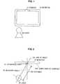
- FIG. 1is a diagram (Part 1) to explain an overview of the present embodiment.
- a user 30is a person who views video displayed in a monitor 19 provided with a display apparatus (not shown) such as a TV set.
- the present embodimentmakes video providing a sense of perspective being displayed possible by performing enhancement processing in accordance with the line of sight of the user 30.
- the enhancement processingis video processing performed in such a way that the video is presented to the user 30 more sharply or, as described above, processing to improve sharpness of video so that sharper video is presented to the user 30.
- the monitor 19has a camera 11 and the camera 11 is assumed to have a function to shoot the user 30. It is also assumed that the display apparatus (not shown) having the monitor 19 has internally a function to perform video processing and enhancement processing can be realized, for example, by the function.
- FIG. 2is a diagram (Part 2) to explain the overview of the present embodiment.
- FIG. 2is a perspective view of the monitor 19 shown in FIG. 1 from above.
- the point on the monitor 19 on which the user 30 focuses attentionis an attention point 41.
- the attention point 41is an intersection point of a line of sight 43 of the user 30 and a video display surface 19A of the monitor 19.
- an incident angle 47 of the line of sight 43 to the video display surface 19A and a distance 40, which is the shortest distance between the user 30 and the attention point 41,are specified.
- enhancement processing in accordance with each of the incident angle 47 and the distance 40will also be described.
- the display apparatusdetects the direction of the line of sight 43 of the user 30 using the camera 11 (See FIG. 1 ) and, based on the direction thereof, performs enhancement processing of video to be output to the monitor 19.
- a high gain amountis set to pixels on the monitor 19 positioned near the attention point 41. Accordingly, video that is easy to view for the user 30 and provides a sense of perspective can be provided to the user 30.
- the gain amountis a value indicating brightness of each pixel constituting the monitor 19 and refers to the luminance of each of red, green, and blue making up colors.
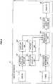
- FIG. 3is a function configuration diagram showing the function configuration of a display apparatus according to the present embodiment.
- the function configuration of a display apparatus according to the present embodimentwill be described with reference to FIG. 3 ( FIG.1 and FIG. 2 are referenced when necessary).
- the display apparatus 10which is an apparatus (such as a TV set) to display video, includes at least the camera 11, a tuner 12, a user video information input unit 110, a sight line detection unit 120, a display video information input unit 150, an enhancement processing unit 160, a display video output control unit 170, and the monitor 19. As shown in FIG. 3 , the display apparatus 10 may further include a user position detection unit 130 or a distance calculation unit 140.
- the camera 11is used to acquire video information of the user 30 by shooting the user 30.
- the camera 11may be, as shown in FIG. 3 , contained in the display apparatus 10 or externally connectable to the display apparatus 10.
- the user video information input unit 110is used to receive input of user video information, which is acquired by the camera 11 and video information of the user 30 watching video displayed in the monitor 19.
- the user video information input unit 110is constituted, for example, by a USB (Universal Serial Bus) interface.
- the sight line detection unit 120is used to detect a line of sight of the user 30 by analyzing user video information whose input is received by the user video information input unit 110.
- the technology to detect the line of sight of the user 30is not specifically limited. Such a technology is provided, for example, at "Prof. Kenzo Kurihara, [online], [Search on June 11, 2008], Internet ⁇ URL: http://joint.idec.or.jp/koryu/020426_2.php>".
- the sight line detection unit 120is constituted by a CPU (Central Processing Unit) or the like.
- the function of the sight line detection unit 120is realized by a program stored in a ROM (Read Only Memory) or the like being expanded into a RAM (Random Access Memory) or the like and the program expanded in the RAM being executed by the CPU.
- the sight line detection unit 120may also be constituted, for example, by dedicated hardware.
- the tuner 12is used to select radio waves of an intended frequency from received radio waves to reproduce video displayed in the monitor 19 from the selected radio waves.
- videomay be reproduced by using a DVD (digital versatile disk) player or the like.
- the display video information input unit 150is used to receive input of display video information to be a source of video displayed in the monitor 19.
- the display video information input unit 150is constituted, for example, by dedicated hardware.
- the enhancement processing unit 160is used to detect an intersection point of the line of sight 43 of the user 30 detected by the sight line detection unit 120 and the video display surface 19A of the monitor 19 as the attention point 41, which is a point on which the user 30 focuses attention.
- the enhancement processing unit 160is used to perform enhancement processing for the monitor 19 by setting a higher gain amount in stages from a position of a longer distance from the detected attention point 41 toward a position of a smaller distance.
- the enhancement processing unit 160sets a higher gain amount in stages, among a plurality of regions divided by one or a plurality of concentric circles around the attention point 41, from a region of a longer distance from the detected attention point 41 toward a region of a smaller distance.
- the enhancement processing unit 160has one or a plurality of concentric circles whose radius is obtained by successively increasing the distance from the attention point 41 by an increment of a predetermined length (See FIG. 4 ).
- the predetermined lengthis assumed to be stored, for example, in the enhancement processing unit 160.
- the enhancement processing unit 160defines the predetermined length as being equal to or less than the distance between adjacent pixels constituting the monitor 19 (See FIG. 5 ). Accordingly, the plurality of regions divided by one or a plurality of concentric circles around the attention point 41 can be made narrower so that the gain amount changes continuously when viewed from the user 30. Therefore, video displayed in the monitor 19 can further be made to naturally generate a sense of perspective.
- the enhancement processing unit 160may have one or a plurality of concentric circles around the attention point 41 as ellipses having a ratio matching the aspect ratio of the monitor 19 as the major axis/minor axis ratio (ratio of the length of the major axis to that of the minor axis) (See FIG. 6 ). Accordingly, video displayed in the monitor 19 can be made to generate a sense of perspective fitting to the form of the monitor 19.
- the enhancement processing unit 160is constituted by a CPU or the like.
- the function of the enhancement processing unit 160is realized by a program stored in a ROM or the like being expanded into a RAM or the like and the program expanded in the RAM being executed by the CPU.
- the enhancement processing unit 160may also be constituted, for example, by dedicated hardware.
- the display video output control unit 170is used to output video via the monitor 19 based on the gain amount set by the enhancement processing unit 160 and display video information whose input is received by the display video information input unit 150.
- the display video output control unit 170is constituted by dedicated hardware.
- the monitor 19is used to display video.
- the monitor 19may be, as shown in FIG. 1 , contained in the display apparatus 10 or externally connectable to the display apparatus 10.
- the user position detection unit 130is used to detect the position of the user 30.
- a technology to detect the position of the user 30will be described later with reference to FIG. 8 , but the present embodiment is not limited to the technology.
- the user position detection unit 130is constituted by a CPU or the like.
- the function of the user position detection unit 130is realized by a program stored in a ROM or the like being expanded into a RAM or the like and the program expanded in the RAM being executed by the CPU.
- the user position detection unit 130may also be constituted, for example, by dedicated hardware.
- the enhancement processing unit 160can set the gain amount by a different technology from the technology described above. The technology will be described below with reference to FIG. 7 .
- the distance calculation unit 140is used to calculate the distance between the monitor 19 and the user 30.
- An exemplary technology to calculate the distance between the monitor 19 and the user 30will be described later with reference to FIG. 9 , but the present embodiment is not limited to the technology.
- the enhancement processing unit 160can set the gain amount by a different technology from the technology described above. That is, with an increasing distance between the monitor 19 and the user 30 calculated by the distance calculation unit 140, a higher gain amount can be set in stages. Accordingly, weaker enhancement processing is performed when watched from a relatively short distance and stronger enhancement processing when watched from a relatively long distance so that video of almost the same appearance can be displayed in both cases when viewed from the user 30.
- the user video information input unit 110, the sight line detection unit 120, the user position detection unit 130, the distance calculation unit 140, the display video information input unit 150, the enhancement processing unit 160, and the display video output control unit 170are constituted by LSI (Large Scale Integration) or the like and are central devices of the display apparatus 10.
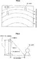
- FIG. 4is a diagram schematically showing an example (Part 1) of enhancement processing performed by an enhancement processing unit according to the present embodiment. An example of enhancement processing performed by an enhancement processing unit according to the present embodiment will be described with reference to FIG. 4 .
- FIG. 4shows that an aspect when the monitor 19 is viewed from the front is schematically shown above a reference line 50 and that when the monitor 19 is viewed from above is schematically shown below the reference line 50 (This also applies to FIG. 6 and FIG. 7 ).
- the sight line detection unit 120detects the line of sight 43 of the user 30.
- the enhancement processing unit 160detects an intersection point of the line of sight 43 of the user 30 detected by the sight line detection unit 120 and the video display surface 19A of the monitor 19 as the attention point 41, which is a point on which the user 30 focuses attention.
- the enhancement processing unit 160also performs enhancement processing for the monitor 19 by setting a higher gain amount in stages from a position of a longer distance from the detected attention point 41 toward a position of a smaller distance.
- the enhancement processing unit 160has two concentric circles whose radius is obtained by successively increasing the distance from the attention point 41 by an increment of a predetermined length when the gain amount is set.
- FIG. 5is a diagram schematically showing the example (Part 2) of enhancement processing performed by the enhancement processing unit according to the present embodiment. An example of enhancement processing performed by the enhancement processing unit according to the present embodiment will be described with reference to FIG. 5 .
- FIG. 5shows that an aspect when the monitor 19 is viewed from the front is shown and graphs for "Application for discontinuous gains” and “Application for continuous gains” are shown thereunder.
- the video display surface 19Ais divided into three regions by these concentric circles. If a higher gain amount is set in stages from a region of a longer distance from the detected attention point 41 toward a region of a smaller distance, in an implementation outside the scope of the claims of the present application discontinuous gain amounts like the graph "Application for discontinuous gains" shown in FIG. 5 are set by the enhancement processing unit 160.
- the radius of each of the two concentric circles shown in the monitor 19is a radius that is obtained by successively increasing the distance from the attention point 41 by an increment of a predetermined length.
- the enhancement processing unit 160can set the gain amount in such a way that the gain amount changes continuously when viewed from the user 30, by making the predetermined length smaller.
- the predetermined lengthis defined as being equal to or less than the distance between adjacent pixels constituting the monitor 19. Then, continuous gain amounts like the graph "Application for continuous gains" shown in FIG. 5 are set by the enhancement processing unit 160.
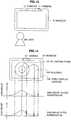
- FIG. 6is a diagram schematically showing the example (Part 3) of enhancement processing performed by the enhancement processing unit according to the present embodiment. An example of enhancement processing performed by the enhancement processing unit according to the present embodiment will be described with reference to FIG. 6 .
- the enhancement processing unit 160has two concentric circles around the attention point 41 as ellipses having a ratio matching the aspect ratio of the monitor 19 as the major axis/minor axis ratio when the gain amount is set.
- FIG. 7is a diagram schematically showing the example (Part 4) of enhancement processing performed by the enhancement processing unit according to the present embodiment. An example of enhancement processing performed by the enhancement processing unit according to the present embodiment will be described with reference to FIG. 7 .
- the position of the user 30is detected by the user position detection unit 130.
- the enhancement processing unit 160defines a set of intersection points of a group of lines forming a predetermined angle to the line of sight 43 of the user 30 with the position of the user 30 as a reference point and the video display surface 19A of the monitor 19 as a boundary when the gain amount is set.
- each of four auxiliary lines 44corresponds to a group of lines.
- the enhancement processing unit 160divides the monitor 19 into a plurality of regions by the boundary. In the example shown in FIG. 7 , two such angles are set.
- the enhancement processing unit 160sets, among the plurality of regions, a higher gain amount in stages from a region of a longer distance from the detected attention point 41 toward a region of a smaller distance.
- the predetermined angleis assumed to be held, for example, by the enhancement processing unit 160, which may hold different angles in the longitudinal direction and the lateral direction of the monitor 19.
- intersection points of the monitor 19 and the auxiliary lines 44change, which is accompanied by changes of concentric circles.
- the strength of enhancement processing in the innermost concentric circle regionis the same, the size of region where relatively strong enhancement processing is performed increases if the distance between the user 30 and the monitor 19 is long. As a result, the user 30 can maintain the appearance constant to some extent regardless of the distance between the user 30 and the monitor 19.
- the shape of the boundarychanges to an ellipse having a larger major axis ratio with the increasing incident angle 47. Therefore, even if the user 30 watches the monitor 19 obliquely, video displayed in the monitor 19 can further be made to naturally generate a sense of perspective.
- FIG. 8is a diagram schematically showing an example of user position detection processing performed by a user position detection unit according to the present embodiment. An example of user position detection processing performed by a user position detection unit according to the present embodiment will be described with reference to FIG. 8 (Other figures are also referenced if necessary).
- FIG. 8shows an aspect of the user 30 when viewed from a lens of the camera 11.
- FIG. 8further has equidistant curves added thereto and if zooming and others are assumed constant, the distance between the monitor 19 and an object such as the user 30 is represented by equidistant curves.
- Video as shown in FIG. 8is shot by the camera 11 and information thereof is acquired by the user position detection unit 130 via the user video information input unit 110 for analysis. For example, by analyzing video information of the user 30 whose input is received by the user video information input unit 110, the user position detection unit 130 can define the detected position of feet of the user 30 as the position of the user 30.
- the enhancement processing unit 160may set the gain amount by assuming that one angle or each of a plurality of angles formed with the line sight 43 is successively increased by an increment of a predetermined angle.
- FIG. 9is a diagram schematically showing an example of distance calculation processing performed by a distance calculation unit according to the present embodiment. An example of distance calculation processing performed by a distance calculation unit according to the present embodiment will be described with reference to FIG. 9 .
- the relative position of the camera 11 to the monitor 19is fixed.
- the position of the user 30 when the monitor 19 is set as a reference positioncan be calculated using the relative position and a relative position of the user 30 when the camera 11 is set as a reference position detected by the user position detection unit 130, so that the distance 40 can be calculated.
- the enhancement processing unit 160can perform enhancement processing appropriate for a distance between the monitor 19 and the user 30 by considering the distance. For example, by setting a higher gain amount in stages with an increasing distance between the monitor 19 and the user 30, enhancement processing for the monitor 19 can be performed. In this manner, sharp video can be watched even if the user 30 is apart from the monitor 19.
- FIG. 10is a diagram illustrating a case in which a plurality of users is present. A case in which the plurality of users is present will be described with reference to FIG. 10 .
- FIG. 10shows a case in which the number of the users 30 present is two as an example of a case in which a plurality of the users 30 is present. In this case, more precise enhancement processing can be performed by performing existing processing when the number of the users 30 is one for two persons.
- enhancement processingcan be performed on different regions based on information about each of the different regions. The processing can also be applied when the number of the users 30 is three or more.
- the sight line detection unit 120detects the lines of sight of the users 30 by detecting a plurality of lines of sight as a line of sight of each of the plurality of the users 30.
- the enhancement processing unit 160detects intersection points of the line of sight of each of the plurality of the users 30 detected by the sight line detection unit 120 and the video display surface 19A of the monitor 19 as each attention point, which is a point on which each of the plurality of the users 30 focuses attention.
- the enhancement processing unit 160performs enhancement processing by setting a higher gain amount from a long distance from each attention point toward a shorter position and superimposing the gain amount on each attention point.
- FIG. 11is a diagram illustrating how to apply a gain when the plurality of users is present. How to apply a gain when the plurality of users is present will be described with reference to FIG. 11 .
- FIG. 11shows that concentric circles around each of the two attention points 41 are overlapped.
- the enhancement processing unit 160calculates the gain amount separately for the plurality of the users 30, each gain amount will be like "Gain amount before superimposition" in FIG. 11 .
- the enhancement processing unit 160adds each gain amount calculated separately. That is, each gain amount is superimposed.
- the result of superimpositionwill be like "Gain amount after superimposition" in FIG. 11 .
- the gain amount after superimpositionexceeds a predetermined range or becomes larger than a preset threshold value, the gain amount can be adjusted by calculation such as a subtraction of a fixed value from the gain amount after superimposition or a multiplication by a value less than 1.
- FIG. 12is a flow chart showing a flow of processing performed by the display apparatus according to the present embodiment. The flow of processing performed by the display apparatus according to the present embodiment will be described with reference to FIG. 12 (Other figures are also referenced if necessary). Here, it is assumed that the number n of the user 30 is present.
- the user video information input unit 110receives input of user video information, which is acquired by the camera 11 and video information of the user 30 watching video displayed in the monitor 19. Subsequently, the sight line detection unit 120 analyzes the user video information whose input is received by the user video information input unit 110 to detect the number of the users 30 (step S101).
- the display apparatus 10performs processing (step S102 to step S106) repeating as many times as the number of the users 30 (n persons) detected by the sight line detection unit 120.
- the sight line detection unit 120detects the lines of sight 43 of the users 30 (step S103). Then, the distance calculation unit 140 calculates the distance 40 between the user 30 and the monitor 19 (step S104). The enhancement processing unit 160 calculates the gain amount of each pixel in the monitor 19 from the line of sight 43 and the distance 40 (step S105).
- the enhancement processing unit 160determines whether the number n of the users 30 is larger than 1 (step S107). If the number n of the users 30 is determined to be larger than 1 ("YES" at step S107), the enhancement processing unit 160 superimposes calculated gain amounts (step S108) before proceeding to step S109. If the number n of the users 30 is determined to be equal to or less than 1 ("NO" at step S107), the enhancement processing unit 160 proceeds to step S109.
- the enhancement processing unit 160sets the gain amount (step S109) and determines whether a predetermined time has passed (step S110). If the predetermined time is determined not to have passed ("NO" at step S110), the enhancement processing unit 160 waits until the predetermined time has passed. If the predetermined time is determined to have passed ("YES" at step S110), the enhancement processing unit 160 returns to step S101 to repeat the processing.
- FIG. 13is a diagram illustrating a case in which a plurality of cameras is present. A case in which a plurality of cameras is present will be described with reference to FIG. 13 .
- FIG. 14is a diagram illustrating a case in which an existing method and a method according to the present embodiment are combined. A case in which an existing method and a method according to the present embodiment are combined will be described with reference to FIG. 14 .
- the existing methodis assumed to be a method that sets the gain amount in accordance with video content.
- videocontains, for example, a building 19B and enhancement processing according to the existing method has been performed on edges thereof.
- each gain amountwill be like "Gain amount before superimposition" in FIG. 14 .
- the enhancement processing unit 160superimposes the gain amount set by the existing method and that set by a method according to the present embodiment.
- the result of superimpositionis, for example, like "Gain amount after superimposition" in FIG. 14 .
- the gain amount after superimpositionexceeds a predetermined range or becomes larger than a preset threshold value, the gain amount can be adjusted by calculation such as a subtraction of a fixed value from the gain amount after superimposition or a multiplication by a value less than 1.
- Enhancement processingis not limited to the above combination and a plurality of types of enhancement processing can be combined for processing.
- a method that performs enhancement processing on a focused region by a method according to the present embodimentis a method 1.
- a method that detects a face portion by adaptive processing of video itself and makes enhancement processing weaker to make video of the portion more desirable videois a method 2.
- the user 30can watch more desirable video by performing integrated enhancement processing considering both the method 1 and the method 2 than when enhancement processing is performed separately.
- enhancement processingcan be performed while retaining advantages of the existing method.
- enhancement processing suiting the user's 30 preferencecan be performed compared with a case in which enhancement processing is performed based on information of video itself by controlling strength of the enhancement processing around the attention point 41 on which the user 30 himself (herself) focuses attention. Further, video providing a sense of perspective can be displayed in accordance with the line of sight of the user.
- appropriate enhancement processing for different spatial relationshipsfor example, when viewed from the front and obliquely can be performed by detecting the position and the line of sight 43 of the user 30.
Landscapes
- Engineering & Computer Science (AREA)
- Multimedia (AREA)
- Signal Processing (AREA)
- Health & Medical Sciences (AREA)
- Social Psychology (AREA)
- General Health & Medical Sciences (AREA)
- Computer Hardware Design (AREA)
- Theoretical Computer Science (AREA)
- General Physics & Mathematics (AREA)
- Physics & Mathematics (AREA)
- Computer Networks & Wireless Communication (AREA)
- Databases & Information Systems (AREA)
- Two-Way Televisions, Distribution Of Moving Picture Or The Like (AREA)
- User Interface Of Digital Computer (AREA)
- Position Input By Displaying (AREA)
- Image Analysis (AREA)
- Image Processing (AREA)
- Transforming Electric Information Into Light Information (AREA)
- Controls And Circuits For Display Device (AREA)
Description
- The present invention relates to a display apparatus and a display method. More particularly, the present invention relates to a display apparatus capable of displaying video providing a sense of perspective in accordance with the line of sight of a user and a display method.
- In related art, enhancement processing adapted to video itself to be output to a monitor has been performed. Here, the enhancement processing is processing to improve sharpness of video so that sharper video is presented to the user. However, enhancement processing adapted to video itself to be output to a monitor does not have in most cases three-dimensional information added to the video itself and thus, the video after being processed may be different from what the user likes.
- Moreover, for example, in Japanese Patent Application published as
JP2000221953 - [Patent Document 1] Japanese Patent Application published as
JP2000221953 - However, according to the technology disclosed in
JP2000221953 - Document
US 6 002 386 A (Gu Sung-Jin) dated 14 December 1999 describes an automatic contrast control circuit for a display apparatus including a distance detector installed on a front panel of the display for detecting a distance existing between a user and the front panel. - Document
US 2006/192847 (Watanabe ISAO) dated 31 August 2006 describes a display apparatus configured to acquire a distance between a display surface of a display unit and a viewer of the display surface. - Document
JP 04 132487 (Matsushita Electric Co Ltd) dated 6 May 1992 - Document
JP 01 290385 (Mitsubishi Electric Corp) dated 22 November 1989 - Document
JP H07-13552 - Document
JP 2000-132152 - The present invention has been made in view of the above issue, and it is desirable to provide a technology capable of displaying video providing a sense of perspective in accordance with the line of sight of the user.
- The present invention is defined in the appended set of claims.
- According to an embodiment of the present invention, there is provided a display apparatus, including:
a monitor; a display video information input unit operable to receive display video information of video displayed in the monitor; a camera; a user video information input unit operable to receive user video information, acquired by the camera, of a user watching video displayed in the monitor; a sight line detection unit that detects a line of sight of the user by analyzing the user video information received by the user video information input unit; an enhancement processing unit that detects an intersection point of the line of sight of the user detected by the sight line detection unit and a video display surface of the monitor as an attention point and performs enhancement processing for the monitor by performing enhancement in stages among a plurality of regions within said video display surface including a region containing the attention point and a region not containing the attention point; and a display video output control unit operable to output video via the monitor based on the enhancement performed by the enhancement processing unit and the display video information received by the display video information input unit; the enhancement processing unit being configured to perform said enhancement by setting a higher enhancement gain amount in stages among a plurality of regions divided by one or a plurality of concentric circles around the attention point within said video display surface, from the region of a longer distance from the attention point toward the region of a smaller distance and to set the gain amount for each region, each region being defined by a radius of the one concentric circle or each of the plurality of concentric circles by successively increasing the distance from the attention point by an increment of a predetermined length, and to define the predetermined length as being equal to or less than the distance between adjacent pixels constituting the monitor. - According to the above configuration, sharpness of video displayed in a portion of a high degree of attention by the user can be improved. Thus, video providing a sense of perspective in accordance with the line of sight of the user can be displayed.
- According to the embodiments of the present invention described above, it becomes possible to display video providing a sense of perspective in accordance with the line of sight of the user.
FIG. 1 is a diagram (Part 1) to explain an overview of a present embodiment;FIG. 2 is a diagram (Part 2) to explain the overview of the present embodiment;FIG. 3 is a function configuration diagram showing a function configuration of a display apparatus according to the present embodiment;FIG. 4 is a diagram schematically showing an example (Part 1) of enhancement processing performed by an enhancement processing unit according to the present embodiment;FIG. 5 is a diagram schematically showing the example (Part 2) of the enhancement processing performed by the enhancement processing unit according to the present embodiment;FIG. 6 is a diagram schematically showing the example (Part 3) of the enhancement processing performed by the enhancement processing unit according to the present embodiment;FIG. 7 is a diagram schematically showing the example (Part 4) of the enhancement processing performed by the enhancement processing unit according to the present embodiment;FIG. 8 is a diagram schematically showing an example of user position detection processing performed by a user position detection unit according to the present embodiment;FIG. 9 is a diagram schematically showing an example of distance calculation processing performed by a distance calculation unit according to the present embodiment;FIG. 10 is a diagram illustrating a case in which a plurality of users is present;FIG. 11 is a diagram illustrating how to apply a gain when the plurality of users is present;FIG. 12 is a flow chart showing a flow of processing performed by the display apparatus according to the present embodiment;FIG. 13 is a diagram illustrating a case in which a plurality of cameras is present; andFIG. 14 is a diagram illustrating a case in which an existing method and a method according to the present embodiment are combined.- Hereafter, preferred embodiments of the present invention will be described in detail with reference to the appended drawings. Note that in this specification and the appended drawings, structural elements that have substantially the same functions and structures are denoted with the same reference numerals and a repeated explanation of these structural elements is omitted.
- First, an overview of the present embodiment is provided to facilitate an understanding about the present embodiment.
FIG. 1 is a diagram (Part 1) to explain an overview of the present embodiment. As shown inFIG. 1 , a user 30 is a person who views video displayed in amonitor 19 provided with a display apparatus (not shown) such as a TV set. The present embodiment makes video providing a sense of perspective being displayed possible by performing enhancement processing in accordance with the line of sight of the user 30. Here, the enhancement processing is video processing performed in such a way that the video is presented to the user 30 more sharply or, as described above, processing to improve sharpness of video so that sharper video is presented to the user 30. Themonitor 19 has acamera 11 and thecamera 11 is assumed to have a function to shoot the user 30. It is also assumed that the display apparatus (not shown) having themonitor 19 has internally a function to perform video processing and enhancement processing can be realized, for example, by the function.FIG. 2 is a diagram (Part 2) to explain the overview of the present embodiment.FIG. 2 is a perspective view of themonitor 19 shown inFIG. 1 from above.- As shown in
FIG. 2 , the point on themonitor 19 on which the user 30 focuses attention is anattention point 41. Theattention point 41 is an intersection point of a line ofsight 43 of the user 30 and avideo display surface 19A of themonitor 19. Moreover, anincident angle 47 of the line ofsight 43 to thevideo display surface 19A and adistance 40, which is the shortest distance between the user 30 and theattention point 41, are specified. In the present embodiment, enhancement processing in accordance with each of theincident angle 47 and thedistance 40 will also be described. - In the present embodiment, the display apparatus (not shown) detects the direction of the line of
sight 43 of the user 30 using the camera 11 (SeeFIG. 1 ) and, based on the direction thereof, performs enhancement processing of video to be output to themonitor 19. In the enhancement processing, a high gain amount is set to pixels on themonitor 19 positioned near theattention point 41. Accordingly, video that is easy to view for the user 30 and provides a sense of perspective can be provided to the user 30. Here, the gain amount is a value indicating brightness of each pixel constituting themonitor 19 and refers to the luminance of each of red, green, and blue making up colors. FIG. 3 is a function configuration diagram showing the function configuration of a display apparatus according to the present embodiment. The function configuration of a display apparatus according to the present embodiment will be described with reference toFIG. 3 (FIG.1 and FIG. 2 are referenced when necessary).- As shown in
FIG. 3 , thedisplay apparatus 10, which is an apparatus (such as a TV set) to display video, includes at least thecamera 11, atuner 12, a user videoinformation input unit 110, a sightline detection unit 120, a display videoinformation input unit 150, anenhancement processing unit 160, a display videooutput control unit 170, and themonitor 19. As shown inFIG. 3 , thedisplay apparatus 10 may further include a userposition detection unit 130 or adistance calculation unit 140. - The
camera 11 is used to acquire video information of the user 30 by shooting the user 30. Thecamera 11 may be, as shown inFIG. 3 , contained in thedisplay apparatus 10 or externally connectable to thedisplay apparatus 10. - The user video
information input unit 110 is used to receive input of user video information, which is acquired by thecamera 11 and video information of the user 30 watching video displayed in themonitor 19. The user videoinformation input unit 110 is constituted, for example, by a USB (Universal Serial Bus) interface. - The sight
line detection unit 120 is used to detect a line of sight of the user 30 by analyzing user video information whose input is received by the user videoinformation input unit 110. The technology to detect the line of sight of the user 30 is not specifically limited. Such a technology is provided, for example, at "Prof. Kenzo Kurihara, [online], [Search on June 11, 2008], Internet <URL: http://joint.idec.or.jp/koryu/020426_2.php>". The sightline detection unit 120 is constituted by a CPU (Central Processing Unit) or the like. In this case, the function of the sightline detection unit 120 is realized by a program stored in a ROM (Read Only Memory) or the like being expanded into a RAM (Random Access Memory) or the like and the program expanded in the RAM being executed by the CPU. The sightline detection unit 120 may also be constituted, for example, by dedicated hardware. - The
tuner 12 is used to select radio waves of an intended frequency from received radio waves to reproduce video displayed in themonitor 19 from the selected radio waves. Instead of using thetuner 12, video may be reproduced by using a DVD (digital versatile disk) player or the like. - The display video
information input unit 150 is used to receive input of display video information to be a source of video displayed in themonitor 19. The display videoinformation input unit 150 is constituted, for example, by dedicated hardware. - The
enhancement processing unit 160 is used to detect an intersection point of the line ofsight 43 of the user 30 detected by the sightline detection unit 120 and thevideo display surface 19A of themonitor 19 as theattention point 41, which is a point on which the user 30 focuses attention. Theenhancement processing unit 160 is used to perform enhancement processing for themonitor 19 by setting a higher gain amount in stages from a position of a longer distance from the detectedattention point 41 toward a position of a smaller distance. - When the gain amount is set, the
enhancement processing unit 160 sets a higher gain amount in stages, among a plurality of regions divided by one or a plurality of concentric circles around theattention point 41, from a region of a longer distance from the detectedattention point 41 toward a region of a smaller distance. - Further, when the gain amount is set, the
enhancement processing unit 160 has one or a plurality of concentric circles whose radius is obtained by successively increasing the distance from theattention point 41 by an increment of a predetermined length (SeeFIG. 4 ). The predetermined length is assumed to be stored, for example, in theenhancement processing unit 160. - When the gain amount is set, the
enhancement processing unit 160 defines the predetermined length as being equal to or less than the distance between adjacent pixels constituting the monitor 19 (SeeFIG. 5 ). Accordingly, the plurality of regions divided by one or a plurality of concentric circles around theattention point 41 can be made narrower so that the gain amount changes continuously when viewed from the user 30. Therefore, video displayed in themonitor 19 can further be made to naturally generate a sense of perspective. - Further, when the gain amount is set, the
enhancement processing unit 160 may have one or a plurality of concentric circles around theattention point 41 as ellipses having a ratio matching the aspect ratio of themonitor 19 as the major axis/minor axis ratio (ratio of the length of the major axis to that of the minor axis) (SeeFIG. 6 ). Accordingly, video displayed in themonitor 19 can be made to generate a sense of perspective fitting to the form of themonitor 19. The aspect ratio of themonitor 19 may be made, for example, length : breadth = 16 : 9 or the like, but is not specifically limited. - The
enhancement processing unit 160 is constituted by a CPU or the like. In this case, the function of theenhancement processing unit 160 is realized by a program stored in a ROM or the like being expanded into a RAM or the like and the program expanded in the RAM being executed by the CPU. Theenhancement processing unit 160 may also be constituted, for example, by dedicated hardware. - The display video
output control unit 170 is used to output video via themonitor 19 based on the gain amount set by theenhancement processing unit 160 and display video information whose input is received by the display videoinformation input unit 150. For example, the display videooutput control unit 170 is constituted by dedicated hardware. - The
monitor 19 is used to display video. Themonitor 19 may be, as shown inFIG. 1 , contained in thedisplay apparatus 10 or externally connectable to thedisplay apparatus 10. - The user
position detection unit 130 is used to detect the position of the user 30. A technology to detect the position of the user 30 will be described later with reference toFIG. 8 , but the present embodiment is not limited to the technology. - The user
position detection unit 130 is constituted by a CPU or the like. In this case, the function of the userposition detection unit 130 is realized by a program stored in a ROM or the like being expanded into a RAM or the like and the program expanded in the RAM being executed by the CPU. The userposition detection unit 130 may also be constituted, for example, by dedicated hardware. - If the
display apparatus 10 further includes the userposition detection unit 130, theenhancement processing unit 160 can set the gain amount by a different technology from the technology described above. The technology will be described below with reference toFIG. 7 . - The
distance calculation unit 140 is used to calculate the distance between themonitor 19 and the user 30. An exemplary technology to calculate the distance between themonitor 19 and the user 30 will be described later with reference toFIG. 9 , but the present embodiment is not limited to the technology. - If the
display apparatus 10 further includes thedistance calculation unit 140, theenhancement processing unit 160 can set the gain amount by a different technology from the technology described above. That is, with an increasing distance between themonitor 19 and the user 30 calculated by thedistance calculation unit 140, a higher gain amount can be set in stages. Accordingly, weaker enhancement processing is performed when watched from a relatively short distance and stronger enhancement processing when watched from a relatively long distance so that video of almost the same appearance can be displayed in both cases when viewed from the user 30. - The user video
information input unit 110, the sightline detection unit 120, the userposition detection unit 130, thedistance calculation unit 140, the display videoinformation input unit 150, theenhancement processing unit 160, and the display videooutput control unit 170 are constituted by LSI (Large Scale Integration) or the like and are central devices of thedisplay apparatus 10. FIG. 4 is a diagram schematically showing an example (Part 1) of enhancement processing performed by an enhancement processing unit according to the present embodiment. An example of enhancement processing performed by an enhancement processing unit according to the present embodiment will be described with reference toFIG. 4 .- Reference to
FIG. 4 shows that an aspect when themonitor 19 is viewed from the front is schematically shown above areference line 50 and that when themonitor 19 is viewed from above is schematically shown below the reference line 50 (This also applies toFIG. 6 andFIG. 7 ). - The sight
line detection unit 120 detects the line ofsight 43 of the user 30. Theenhancement processing unit 160 detects an intersection point of the line ofsight 43 of the user 30 detected by the sightline detection unit 120 and thevideo display surface 19A of themonitor 19 as theattention point 41, which is a point on which the user 30 focuses attention. Theenhancement processing unit 160 also performs enhancement processing for themonitor 19 by setting a higher gain amount in stages from a position of a longer distance from the detectedattention point 41 toward a position of a smaller distance. Here, in the example shown inFIG. 4 , theenhancement processing unit 160 has two concentric circles whose radius is obtained by successively increasing the distance from theattention point 41 by an increment of a predetermined length when the gain amount is set. FIG. 5 is a diagram schematically showing the example (Part 2) of enhancement processing performed by the enhancement processing unit according to the present embodiment. An example of enhancement processing performed by the enhancement processing unit according to the present embodiment will be described with reference toFIG. 5 .- Reference to
FIG. 5 shows that an aspect when themonitor 19 is viewed from the front is shown and graphs for "Application for discontinuous gains" and "Application for continuous gains" are shown thereunder. - Two concentric circles around the
attention point 41 are shown in themonitor 19 and thevideo display surface 19A is divided into three regions by these concentric circles. If a higher gain amount is set in stages from a region of a longer distance from the detectedattention point 41 toward a region of a smaller distance, in an implementation outside the scope of the claims of the present application discontinuous gain amounts like the graph "Application for discontinuous gains" shown inFIG. 5 are set by theenhancement processing unit 160. Here, the radius of each of the two concentric circles shown in themonitor 19 is a radius that is obtained by successively increasing the distance from theattention point 41 by an increment of a predetermined length. - In embodiments of the claimed invention, the
enhancement processing unit 160 can set the gain amount in such a way that the gain amount changes continuously when viewed from the user 30, by making the predetermined length smaller. Notably, the predetermined length is defined as being equal to or less than the distance between adjacent pixels constituting themonitor 19. Then, continuous gain amounts like the graph "Application for continuous gains" shown inFIG. 5 are set by theenhancement processing unit 160. FIG. 6 is a diagram schematically showing the example (Part 3) of enhancement processing performed by the enhancement processing unit according to the present embodiment. An example of enhancement processing performed by the enhancement processing unit according to the present embodiment will be described with reference toFIG. 6 .- In the example shown in
FIG. 6 , theenhancement processing unit 160 has two concentric circles around theattention point 41 as ellipses having a ratio matching the aspect ratio of themonitor 19 as the major axis/minor axis ratio when the gain amount is set. FIG. 7 is a diagram schematically showing the example (Part 4) of enhancement processing performed by the enhancement processing unit according to the present embodiment. An example of enhancement processing performed by the enhancement processing unit according to the present embodiment will be described with reference toFIG. 7 .- In the example shown in
FIG. 7 , the position of the user 30 is detected by the userposition detection unit 130. In such a case, theenhancement processing unit 160 defines a set of intersection points of a group of lines forming a predetermined angle to the line ofsight 43 of the user 30 with the position of the user 30 as a reference point and thevideo display surface 19A of themonitor 19 as a boundary when the gain amount is set. In the example shown inFIG. 7 , each of fourauxiliary lines 44 corresponds to a group of lines. - By setting one or a plurality of such angles, the
enhancement processing unit 160 divides themonitor 19 into a plurality of regions by the boundary. In the example shown inFIG. 7 , two such angles are set. Theenhancement processing unit 160 sets, among the plurality of regions, a higher gain amount in stages from a region of a longer distance from the detectedattention point 41 toward a region of a smaller distance. The predetermined angle is assumed to be held, for example, by theenhancement processing unit 160, which may hold different angles in the longitudinal direction and the lateral direction of themonitor 19. - According to the above assumption, as the user 30 moves away from the
monitor 19, intersection points of themonitor 19 and theauxiliary lines 44 change, which is accompanied by changes of concentric circles. For example, when the strength of enhancement processing in the innermost concentric circle region is the same, the size of region where relatively strong enhancement processing is performed increases if the distance between the user 30 and themonitor 19 is long. As a result, the user 30 can maintain the appearance constant to some extent regardless of the distance between the user 30 and themonitor 19. - When the user 30 watches the
monitor 19 obliquely, the shape of the boundary changes to an ellipse having a larger major axis ratio with the increasingincident angle 47. Therefore, even if the user 30 watches themonitor 19 obliquely, video displayed in themonitor 19 can further be made to naturally generate a sense of perspective. FIG. 8 is a diagram schematically showing an example of user position detection processing performed by a user position detection unit according to the present embodiment. An example of user position detection processing performed by a user position detection unit according to the present embodiment will be described with reference toFIG. 8 (Other figures are also referenced if necessary).FIG. 8 shows an aspect of the user 30 when viewed from a lens of thecamera 11.FIG. 8 further has equidistant curves added thereto and if zooming and others are assumed constant, the distance between themonitor 19 and an object such as the user 30 is represented by equidistant curves. Video as shown inFIG. 8 is shot by thecamera 11 and information thereof is acquired by the userposition detection unit 130 via the user videoinformation input unit 110 for analysis. For example, by analyzing video information of the user 30 whose input is received by the user videoinformation input unit 110, the userposition detection unit 130 can define the detected position of feet of the user 30 as the position of the user 30.- The
enhancement processing unit 160 may set the gain amount by assuming that one angle or each of a plurality of angles formed with theline sight 43 is successively increased by an increment of a predetermined angle. FIG. 9 is a diagram schematically showing an example of distance calculation processing performed by a distance calculation unit according to the present embodiment. An example of distance calculation processing performed by a distance calculation unit according to the present embodiment will be described with reference toFIG. 9 .- As shown in
FIG. 9 , the relative position of thecamera 11 to themonitor 19 is fixed. Thus, the position of the user 30 when themonitor 19 is set as a reference position can be calculated using the relative position and a relative position of the user 30 when thecamera 11 is set as a reference position detected by the userposition detection unit 130, so that thedistance 40 can be calculated. - When the
display apparatus 10 further includes thedistance calculation unit 140, theenhancement processing unit 160 can perform enhancement processing appropriate for a distance between themonitor 19 and the user 30 by considering the distance. For example, by setting a higher gain amount in stages with an increasing distance between themonitor 19 and the user 30, enhancement processing for themonitor 19 can be performed. In this manner, sharp video can be watched even if the user 30 is apart from themonitor 19. FIG. 10 is a diagram illustrating a case in which a plurality of users is present. A case in which the plurality of users is present will be described with reference toFIG. 10 .FIG. 10 shows a case in which the number of the users 30 present is two as an example of a case in which a plurality of the users 30 is present. In this case, more precise enhancement processing can be performed by performing existing processing when the number of the users 30 is one for two persons.- If, for example, the two users 30 turn the lines of sight on the same region, stronger enhancement processing can be performed around the region. If the two users 30 turn the lines of
sight 43 on different regions, enhancement processing can be performed on different regions based on information about each of the different regions. The processing can also be applied when the number of the users 30 is three or more. - More specifically, the sight
line detection unit 120 detects the lines of sight of the users 30 by detecting a plurality of lines of sight as a line of sight of each of the plurality of the users 30. Theenhancement processing unit 160 detects intersection points of the line of sight of each of the plurality of the users 30 detected by the sightline detection unit 120 and thevideo display surface 19A of themonitor 19 as each attention point, which is a point on which each of the plurality of the users 30 focuses attention. Theenhancement processing unit 160 performs enhancement processing by setting a higher gain amount from a long distance from each attention point toward a shorter position and superimposing the gain amount on each attention point. FIG. 11 is a diagram illustrating how to apply a gain when the plurality of users is present. How to apply a gain when the plurality of users is present will be described with reference toFIG. 11 .- Reference to
FIG. 11 shows that concentric circles around each of the two attention points 41 are overlapped. In such a case, if theenhancement processing unit 160 calculates the gain amount separately for the plurality of the users 30, each gain amount will be like "Gain amount before superimposition" inFIG. 11 . - Then, the
enhancement processing unit 160 adds each gain amount calculated separately. That is, each gain amount is superimposed. The result of superimposition will be like "Gain amount after superimposition" inFIG. 11 . However, if, as a result of superimposition, the gain amount after superimposition exceeds a predetermined range or becomes larger than a preset threshold value, the gain amount can be adjusted by calculation such as a subtraction of a fixed value from the gain amount after superimposition or a multiplication by a value less than 1. FIG. 12 is a flow chart showing a flow of processing performed by the display apparatus according to the present embodiment. The flow of processing performed by the display apparatus according to the present embodiment will be described with reference toFIG. 12 (Other figures are also referenced if necessary). Here, it is assumed that the number n of the user 30 is present.- The user video
information input unit 110 receives input of user video information, which is acquired by thecamera 11 and video information of the user 30 watching video displayed in themonitor 19. Subsequently, the sightline detection unit 120 analyzes the user video information whose input is received by the user videoinformation input unit 110 to detect the number of the users 30 (step S101). Thedisplay apparatus 10 performs processing (step S102 to step S106) repeating as many times as the number of the users 30 (n persons) detected by the sightline detection unit 120. - In the repetitive processing, the sight
line detection unit 120 detects the lines ofsight 43 of the users 30 (step S103). Then, thedistance calculation unit 140 calculates thedistance 40 between the user 30 and the monitor 19 (step S104). Theenhancement processing unit 160 calculates the gain amount of each pixel in themonitor 19 from the line ofsight 43 and the distance 40 (step S105). - When the repetitive processing ends, the
enhancement processing unit 160 determines whether the number n of the users 30 is larger than 1 (step S107). If the number n of the users 30 is determined to be larger than 1 ("YES" at step S107), theenhancement processing unit 160 superimposes calculated gain amounts (step S108) before proceeding to step S109. If the number n of the users 30 is determined to be equal to or less than 1 ("NO" at step S107), theenhancement processing unit 160 proceeds to step S109. - The
enhancement processing unit 160 sets the gain amount (step S109) and determines whether a predetermined time has passed (step S110). If the predetermined time is determined not to have passed ("NO" at step S110), theenhancement processing unit 160 waits until the predetermined time has passed. If the predetermined time is determined to have passed ("YES" at step S110), theenhancement processing unit 160 returns to step S101 to repeat the processing. FIG. 13 is a diagram illustrating a case in which a plurality of cameras is present. A case in which a plurality of cameras is present will be described with reference toFIG. 13 .- As shown in
FIG. 13 , when a plurality of thecameras 11 is present, it is expected that detection will be more precise when the position and line ofsight 43 of the user 30 are detected by shooting the user 30 by the plurality of thecameras 11. FIG. 14 is a diagram illustrating a case in which an existing method and a method according to the present embodiment are combined. A case in which an existing method and a method according to the present embodiment are combined will be described with reference toFIG. 14 .- Here, the existing method is assumed to be a method that sets the gain amount in accordance with video content. As shown in
FIG. 14 , video contains, for example, abuilding 19B and enhancement processing according to the existing method has been performed on edges thereof. In such a case, if the gain amount is calculated separately by each method, each gain amount will be like "Gain amount before superimposition" inFIG. 14 . - The
enhancement processing unit 160 superimposes the gain amount set by the existing method and that set by a method according to the present embodiment. The result of superimposition is, for example, like "Gain amount after superimposition" inFIG. 14 . However, if, as a result of superimposition, the gain amount after superimposition exceeds a predetermined range or becomes larger than a preset threshold value, the gain amount can be adjusted by calculation such as a subtraction of a fixed value from the gain amount after superimposition or a multiplication by a value less than 1. - Enhancement processing is not limited to the above combination and a plurality of types of enhancement processing can be combined for processing. For example, assume that a method that performs enhancement processing on a focused region by a method according to the present embodiment is a
method 1. Further, assume that a method that detects a face portion by adaptive processing of video itself and makes enhancement processing weaker to make video of the portion more desirable video is a method 2. The user 30 can watch more desirable video by performing integrated enhancement processing considering both themethod 1 and the method 2 than when enhancement processing is performed separately. - By combining with an existing method for performing enhancement processing adapted to video itself, enhancement processing can be performed while retaining advantages of the existing method.
- According to the present embodiment, enhancement processing suiting the user's 30 preference can be performed compared with a case in which enhancement processing is performed based on information of video itself by controlling strength of the enhancement processing around the
attention point 41 on which the user 30 himself (herself) focuses attention. Further, video providing a sense of perspective can be displayed in accordance with the line of sight of the user. - Moreover, appropriate enhancement processing for different spatial relationships, for example, when viewed from the front and obliquely can be performed by detecting the position and the line of
sight 43 of the user 30. - The present application contains subject matter related to that disclosed in Japanese Priority Patent Application
JP 2008-173006 filed in the Japan Patent Office on July/2/2008 - It should be understood by those skilled in the art that various modifications, combinations, sub-combinations and alterations may occur depending on design requirements and other factors insofar as they are within the scope of the appended claims or the equivalents thereof.
Claims (12)
- A display apparatus, comprising:a monitor (19);a display video information input unit (150) operable to receive display video information of video displayed in the monitor (19);a camera (11);a user video information input unit (110) operable to receive user video information, acquired by the camera (11), of a user (30) watching video displayed in the monitor (19);a sight line detection unit (120) operable to detect a line of sight of the user (30) by analyzing the user video information received by the user video information input unit (110);an enhancement processing unit (160) operable to detect an intersection point of the line of sight of the user (30) detected by the sight line detection unit (120) and a video display surface of the monitor (19) as an attention point and further configured to perform enhancement processing for the monitor (19) by performing enhancement in stages among a plurality of regions within said video display surface including a region containing the attention point and a region not containing the attention point; anda display video output control unit (170) operable to output video via the monitor (19) based on the enhancement performed by the enhancement processing unit (160) and the display video information received by the display video information input unit (150);characterized in that:
the enhancement processing unit (160) is configured:to perform said enhancement by setting a higher enhancement gain amount in stages among a plurality of regions divided by one or a plurality of concentric circles around the attention point within said video display surface, from the region of a longer distance from the attention point toward the region of a smaller distance,to set the gain amount for each region, each region being defined by a radius of the one concentric circle or each of the plurality of concentric circles by successively increasing the distance from the attention point by an increment of a predetermined length, andto define the predetermined length as being equal to or less than the distance between adjacent pixels constituting the monitor (19). - The display apparatus according to claim 1, wherein
the enhancement processing unit (160) is configured to set the gain amount by defining the one or the plurality of concentric circles around the attention point as ellipses having a ratio matching the aspect ratio of the monitor (19) as the major axis/minor axis ratio. - The display apparatus according to claim 1, further comprising:a user position detection unit (130) operable to detect the position of the user (30), whereinthe enhancement processing unit (160) is further configured to define an additional set of intersection points of a group of lines forming a predetermined angle to the line of sight of the user (30) with the position of the user (30) detected by the user position detection unit (130) as a reference point and the video display surface of the monitor (19) as a boundary, one or a plurality of the angles being set such that each boundary corresponds to one of said concentric circles.
- The display apparatus according to claim 3, wherein
the enhancement processing unit (160) is configured to set the gain amount by obtaining the one angle or each of the plurality of angles by successively increasing the angle formed with the line of sight by an increment of a predetermined angle. - The display apparatus according to any one of claims 1 to 4, further comprising:a distance calculation unit (140) operable to calculate the distance between the monitor (19) and the user (30), whereinthe enhancement processing unit (160) is configured to perform enhancement processing for the monitor (19) by setting the higher gain amount in stages with the increasing distance between the monitor (19) and the user (30) calculated by the distance calculation unit (140).
- The display apparatus according to any one of claims 1 to 4, whereinthe sight line detection unit (120) is configured to detect the line of sight of the user (30) by detecting a plurality of lines of sight as a line of sight of each of a plurality of users (30), and whereinthe enhancement processing unit (160) is configured to detect intersection points of the line of sight of each of the plurality of the users (30) detected by the sight line detection unit (120) and the video display surface of the monitor (19) as each attention point, which is a point on which each of the plurality of users (30) focuses attention and to perform enhancement processing by setting within said video display surface the higher gain amount from the long distance from each attention point toward the shorter position and superimposing the gain amount on each attention point.
- A display method, comprising the steps of:receiving display video information of video displayed in a monitor (19) through a display video information input unit (150);receiving user video information, acquired by a camera (11) of a user (30) watching video displayed in the monitor (19) through a user video information input unit (150);detecting a line of sight of the user (30) by analyzing the user video information received by the user video information input unit (110) through a sight line detection unit (120);detecting an intersection point of the line of sight of the user (30) detected by the sight line detection unit (120) and a video display surface of the monitor (19) as an attention point and performing enhancement processing for the monitor (19) by performing enhancement in stages among a plurality of regions within said video display surface including a region containing the attention point and a region not containing the attention point; andoutputting video via the monitor (19) based on the gain amount set by the enhancement processing unit (160) and the display video information received by the display video information input unit (150) through a display video output control unit (170);characterized in that:
the enhancement processing comprises:setting a higher enhancement gain amount in stages among a plurality of regions divided by one or a plurality of concentric circles around the attention point within said video display surface, from the region of a longer distance from the attention point toward the region of a smaller distance, andsetting the gain amount for each region, each region being defined by a radius of the one concentric circle or each of the plurality of concentric circles by successively increasing the distance from the attention point by an increment of a predetermined length, wherein the predetermined length is equal to or less than the distance between adjacent pixels constituting the monitor (19). - The display method according to claim 7, wherein
the enhancement processing comprises setting the gain amount by defining the one or the plurality of concentric circles around the attention point as ellipses having a ratio matching the aspect ratio of the monitor (19) as the major axis/minor axis ratio. - The display method according to claim 7, further comprising:detecting the position of the user (30);wherein the enhancement processing further comprises defining an additional set of intersection points of a group of lines forming a predetermined angle to the line of sight of the user (30) with the detected position of the user (30) as a reference point and the video display surface of the monitor (19) as a boundary, one or a plurality of the angles being set such that each boundary corresponds to one of said concentric circles.
- The display method according to claim 9, wherein
the enhancement processing comprises setting the gain amount by obtaining the one angle or each of the plurality of angles by successively increasing the angle formed with the line of sight by an increment of a predetermined angle. - The display method according to any one of claims 7 to 10, further comprising:calculating the distance between the monitor (19) and the user (30);wherein the enhancement processing comprises setting the higher gain amount in stages with the increasing calculated distance between the monitor (19) and the user (30).
- The display method according to any one of claims 7 to 10, whereinthe detecting of the line of sight of the user (30) comprises detecting a plurality of lines of sight as a line of sight of each of a plurality of users (30), and whereinthe enhancement processing comprises detecting intersection points of the line of sight of each of the plurality of the users (30) and the video display surface of the monitor (19) as each attention point, which is a point on which each of the plurality of users (30) focuses attention and performing enhancement processing by setting within said video display surface the higher gain amount from the long distance from each attention point toward the shorter position and superimposing the gain amount on each attention point.
Applications Claiming Priority (1)
| Application Number | Priority Date | Filing Date | Title |
|---|---|---|---|
| JP2008173006AJP4743234B2 (en) | 2008-07-02 | 2008-07-02 | Display device and display method |
Publications (2)
| Publication Number | Publication Date |
|---|---|
| EP2141921A1 EP2141921A1 (en) | 2010-01-06 |
| EP2141921B1true EP2141921B1 (en) | 2021-12-15 |
Family
ID=41172316
Family Applications (1)
| Application Number | Title | Priority Date | Filing Date |
|---|---|---|---|
| EP09164394.0AActiveEP2141921B1 (en) | 2008-07-02 | 2009-07-02 | Display apparatus and display method |
Country Status (4)
| Country | Link |
|---|---|
| US (2) | US8619195B2 (en) |
| EP (1) | EP2141921B1 (en) |
| JP (1) | JP4743234B2 (en) |
| CN (1) | CN101635861B (en) |
Families Citing this family (22)
| Publication number | Priority date | Publication date | Assignee | Title |
|---|---|---|---|---|
| CN101894511B (en)* | 2010-07-15 | 2012-03-14 | 鸿富锦精密工业(深圳)有限公司 | Electronic looking board |
| US11070661B2 (en) | 2010-09-21 | 2021-07-20 | Cellepathy Inc. | Restricting mobile device usage |
| US9800716B2 (en) | 2010-09-21 | 2017-10-24 | Cellepathy Inc. | Restricting mobile device usage |
| EP2619911A4 (en) | 2010-09-21 | 2015-05-06 | Cellepathy Ltd | System and method for sensor-based determination of user role, location, and/or state of one of more in-vehicle mobile devices and enforcement of usage thereof |
| EP2759150A4 (en)* | 2011-09-21 | 2015-09-23 | Cellepathy Ltd | Restricting mobile device usage |
| CN102572217B (en)* | 2011-12-29 | 2014-08-20 | 华为技术有限公司 | Visual-attention-based multimedia processing method and device |
| JP6007600B2 (en)* | 2012-06-07 | 2016-10-12 | ソニー株式会社 | Image processing apparatus, image processing method, and program |
| US9691115B2 (en) | 2012-06-21 | 2017-06-27 | Cellepathy Inc. | Context determination using access points in transportation and other scenarios |
| KR102111407B1 (en) | 2013-08-19 | 2020-05-15 | 엘지전자 주식회사 | Display apparatus and method for operating the same |
| KR102149200B1 (en)* | 2013-09-03 | 2020-08-28 | 엘지전자 주식회사 | Input module and image display device having the same |
| KR102244620B1 (en)* | 2014-09-05 | 2021-04-26 | 삼성전자 주식회사 | Method and apparatus for controlling rendering quality |
| WO2016064366A1 (en)* | 2014-10-24 | 2016-04-28 | Echostar Ukraine, L.L.C. | Display device viewing angle compensation |
| CN106060658B (en)* | 2016-05-27 | 2019-06-14 | 青岛海信电器股份有限公司 | A kind of image processing method and device |
| US10714049B2 (en) | 2016-06-06 | 2020-07-14 | Apple Inc. | Electronic display border gain systems and methods |
| EP3632084B1 (en)* | 2017-06-03 | 2021-04-28 | Apple Inc. | Attention detection service |
| US10642335B2 (en) | 2017-06-03 | 2020-05-05 | Apple Inc. | Attention detection service |
| JP2019017800A (en) | 2017-07-19 | 2019-02-07 | 富士通株式会社 | Computer program, information processing device, and information processing method |
| EP3454322A1 (en)* | 2017-09-11 | 2019-03-13 | Apple Inc. | Electronic display border gain systems and methods |
| US20210225305A1 (en)* | 2018-05-21 | 2021-07-22 | Nec Display Solutions, Ltd. | Display device |
| US11209656B1 (en) | 2020-10-05 | 2021-12-28 | Facebook Technologies, Llc | Methods of driving light sources in a near-eye display |
| CN113115086B (en)* | 2021-04-16 | 2023-09-19 | 浙江闪链科技有限公司 | Method for collecting elevator media viewing information based on video line-of-sight identification |
| US11727892B1 (en) | 2022-11-09 | 2023-08-15 | Meta Platforms Technologies, Llc | Eye-tracking based foveation control of displays |
Citations (3)
| Publication number | Priority date | Publication date | Assignee | Title |
|---|---|---|---|---|
| JPH0713552A (en)* | 1993-06-14 | 1995-01-17 | Atr Tsushin Syst Kenkyusho:Kk | Picture display device |
| JP2000132152A (en)* | 1998-10-27 | 2000-05-12 | Sharp Corp | Display device |
| JP2002055675A (en)* | 1999-09-17 | 2002-02-20 | Matsushita Electric Ind Co Ltd | Image display device |
Family Cites Families (22)
| Publication number | Priority date | Publication date | Assignee | Title |
|---|---|---|---|---|
| US2008301A (en)* | 1933-09-25 | 1935-07-16 | Stanley F Gleason | Meat processing and molding device |
| JPH01290385A (en) | 1988-05-17 | 1989-11-22 | Mitsubishi Electric Corp | Television receiver |
| JPH04132487A (en) | 1990-09-25 | 1992-05-06 | Matsushita Electric Ind Co Ltd | Television receiver, its control device and control method |
| JPH04192762A (en)* | 1990-11-26 | 1992-07-10 | Mitsubishi Electric Corp | color television receiver |
| JPH07287761A (en)* | 1994-04-19 | 1995-10-31 | Canon Inc | Image processing apparatus and image processing method |
| KR100265164B1 (en) | 1996-11-08 | 2000-09-15 | 윤종용 | Automatic contrast control circuit and method using distant measuring sensor |
| JPH10282877A (en)* | 1997-04-08 | 1998-10-23 | Canon Inc | Image generation method, image generation device, simulation system, and storage medium |
| JP2000221953A (en) | 1999-01-29 | 2000-08-11 | Sony Corp | Image display device, image processing method, and image display system by applying them |
| CN1189026C (en)* | 1999-04-06 | 2005-02-09 | 皇家菲利浦电子有限公司 | Apparatus and method for signal processing |
| US6954193B1 (en)* | 2000-09-08 | 2005-10-11 | Apple Computer, Inc. | Method and apparatus for correcting pixel level intensity variation |
| JP2002116728A (en)* | 2000-10-10 | 2002-04-19 | Matsushita Electric Ind Co Ltd | Display device |
| JP3620443B2 (en)* | 2000-12-05 | 2005-02-16 | 日産自動車株式会社 | Automotive display device |
| US20030067476A1 (en)* | 2001-10-04 | 2003-04-10 | Eastman Kodak Company | Method and system for displaying an image |
| JP2004213486A (en) | 2003-01-07 | 2004-07-29 | Sony Corp | Image processor and processing method, storage medium, and program |
| JP4038689B2 (en)* | 2004-01-21 | 2008-01-30 | ソニー株式会社 | Display control apparatus and method, recording medium, and program |
| JP2005315956A (en)* | 2004-04-27 | 2005-11-10 | Pioneer Electronic Corp | Display unit driving device and driving method therefor |
| JP4952995B2 (en)* | 2004-06-18 | 2012-06-13 | 日本電気株式会社 | Image display system, image display method, and image display program |
| DE102004057013A1 (en)* | 2004-11-25 | 2006-06-01 | Micronas Gmbh | Video display apparatus and method for processing a video signal to optimize image presentation |
| JP2006235307A (en) | 2005-02-25 | 2006-09-07 | Toshiba Corp | Display device and display control method for the same |
| US7697751B2 (en)* | 2005-12-29 | 2010-04-13 | Graphics Properties Holdings, Inc. | Use of ray tracing for generating images for auto-stereo displays |
| US20080316372A1 (en)* | 2007-06-20 | 2008-12-25 | Ning Xu | Video display enhancement based on viewer characteristics |
| JP4858476B2 (en) | 2008-03-31 | 2012-01-18 | 株式会社日立製作所 | AC motor control device |
- 2008
- 2008-07-02JPJP2008173006Apatent/JP4743234B2/ennot_activeExpired - Fee Related
- 2009
- 2009-07-01USUS12/459,449patent/US8619195B2/enactiveActive
- 2009-07-02EPEP09164394.0Apatent/EP2141921B1/enactiveActive
- 2009-07-02CNCN2009101396823Apatent/CN101635861B/enactiveActive
- 2013
- 2013-11-14USUS14/080,075patent/US8994883B2/enactiveActive
Patent Citations (3)
| Publication number | Priority date | Publication date | Assignee | Title |
|---|---|---|---|---|
| JPH0713552A (en)* | 1993-06-14 | 1995-01-17 | Atr Tsushin Syst Kenkyusho:Kk | Picture display device |
| JP2000132152A (en)* | 1998-10-27 | 2000-05-12 | Sharp Corp | Display device |
| JP2002055675A (en)* | 1999-09-17 | 2002-02-20 | Matsushita Electric Ind Co Ltd | Image display device |
Also Published As
| Publication number | Publication date |
|---|---|
| JP4743234B2 (en) | 2011-08-10 |
| US8994883B2 (en) | 2015-03-31 |
| US20140071296A1 (en) | 2014-03-13 |
| CN101635861A (en) | 2010-01-27 |
| CN101635861B (en) | 2011-06-08 |
| US8619195B2 (en) | 2013-12-31 |
| EP2141921A1 (en) | 2010-01-06 |
| JP2010014836A (en) | 2010-01-21 |
| US20100002072A1 (en) | 2010-01-07 |
Similar Documents
| Publication | Publication Date | Title |
|---|---|---|
| EP2141921B1 (en) | Display apparatus and display method | |
| US9729845B2 (en) | Stereoscopic view synthesis method and apparatus using the same | |
| US9148587B2 (en) | Image processing device, imaging device, image processing method, and non-transitory computer readable medium | |
| EP2613243A2 (en) | Display apparatus and controlling method thereof | |
| JP4720738B2 (en) | Electronics | |
| EP2278824A1 (en) | Video processing apparatus and video processing method | |
| CN106464959B (en) | Semiconductor integrated circuit, display device including the same, and control method | |
| US11275230B2 (en) | Detection apparatus, detection method, detection program, and imaging apparatus | |
| US10182184B2 (en) | Image processing apparatus and image processing method | |
| JP5599063B2 (en) | Display control apparatus, display control method, and program | |
| KR101640947B1 (en) | Display device and viewing-angle control methods inthe same | |
| CN114630053A (en) | HDR image display method and display equipment | |
| US9781343B2 (en) | Image processing apparatus and method for operating image processing apparatus | |
| JP2012173683A (en) | Display control device, information display apparatus, and display control method | |
| US9836812B2 (en) | Image processing apparatus, method, and medium to apply a restrictive condition | |
| EP2629537A2 (en) | Display apparatus and method for adjusting three-dimensional effects | |
| US20110310127A1 (en) | Image processing apparatus, image processing method and program | |
| US8537202B2 (en) | Video processing apparatus and video processing method | |
| US11665327B2 (en) | Image processing apparatus | |
| JP2007256961A (en) | Video signal processing apparatus and method, storage medium, and program | |
| US20100053448A1 (en) | Systems and methods for picture enhancement | |
| JP2009092728A (en) | Image display device, image display method, and program | |
| CN106412514B (en) | Method and device for video processing | |
| JP2010087620A (en) | Video processing device and video processing method | |
| KR20130019258A (en) | Image display apparatus, and method for operating the same |
Legal Events
| Date | Code | Title | Description |
|---|---|---|---|
| PUAI | Public reference made under article 153(3) epc to a published international application that has entered the european phase | Free format text:ORIGINAL CODE: 0009012 | |
| 17P | Request for examination filed | Effective date:20090702 | |
| AK | Designated contracting states | Kind code of ref document:A1 Designated state(s):AT BE BG CH CY CZ DE DK EE ES FI FR GB GR HR HU IE IS IT LI LT LU LV MC MK MT NL NO PL PT RO SE SI SK SM TR | |
| 17Q | First examination report despatched | Effective date:20100819 | |
| RAP1 | Party data changed (applicant data changed or rights of an application transferred) | Owner name:SATURN LICENSING LLC | |
| STAA | Information on the status of an ep patent application or granted ep patent | Free format text:STATUS: EXAMINATION IS IN PROGRESS | |
| REG | Reference to a national code | Ref country code:DE Ref legal event code:R079 Ref document number:602009064210 Country of ref document:DE Free format text:PREVIOUS MAIN CLASS: H04N0005570000 Ipc:G09G0005000000 | |
| RIC1 | Information provided on ipc code assigned before grant | Ipc:H04N 5/57 20060101ALI20201027BHEP Ipc:G09G 5/00 20060101AFI20201027BHEP | |
| GRAP | Despatch of communication of intention to grant a patent | Free format text:ORIGINAL CODE: EPIDOSNIGR1 | |
| STAA | Information on the status of an ep patent application or granted ep patent | Free format text:STATUS: GRANT OF PATENT IS INTENDED | |
| INTG | Intention to grant announced | Effective date:20201221 | |
| GRAJ | Information related to disapproval of communication of intention to grant by the applicant or resumption of examination proceedings by the epo deleted | Free format text:ORIGINAL CODE: EPIDOSDIGR1 | |
| STAA | Information on the status of an ep patent application or granted ep patent | Free format text:STATUS: EXAMINATION IS IN PROGRESS | |
| INTC | Intention to grant announced (deleted) | ||
| GRAP | Despatch of communication of intention to grant a patent | Free format text:ORIGINAL CODE: EPIDOSNIGR1 | |
| STAA | Information on the status of an ep patent application or granted ep patent | Free format text:STATUS: GRANT OF PATENT IS INTENDED | |
| INTG | Intention to grant announced | Effective date:20210702 | |
| GRAS | Grant fee paid | Free format text:ORIGINAL CODE: EPIDOSNIGR3 | |
| GRAA | (expected) grant | Free format text:ORIGINAL CODE: 0009210 | |
| STAA | Information on the status of an ep patent application or granted ep patent | Free format text:STATUS: THE PATENT HAS BEEN GRANTED | |
| AK | Designated contracting states | Kind code of ref document:B1 Designated state(s):AT BE BG CH CY CZ DE DK EE ES FI FR GB GR HR HU IE IS IT LI LT LU LV MC MK MT NL NO PL PT RO SE SI SK SM TR | |
| REG | Reference to a national code | Ref country code:GB Ref legal event code:FG4D Ref country code:CH Ref legal event code:EP | |
| REG | Reference to a national code | Ref country code:IE Ref legal event code:FG4D Ref country code:DE Ref legal event code:R096 Ref document number:602009064210 Country of ref document:DE | |
| REG | Reference to a national code | Ref country code:AT Ref legal event code:REF Ref document number:1456082 Country of ref document:AT Kind code of ref document:T Effective date:20220115 | |
| REG | Reference to a national code | Ref country code:LT Ref legal event code:MG9D | |
| PG25 | Lapsed in a contracting state [announced via postgrant information from national office to epo] | Ref country code:LT Free format text:LAPSE BECAUSE OF FAILURE TO SUBMIT A TRANSLATION OF THE DESCRIPTION OR TO PAY THE FEE WITHIN THE PRESCRIBED TIME-LIMIT Effective date:20211215 Ref country code:FI Free format text:LAPSE BECAUSE OF FAILURE TO SUBMIT A TRANSLATION OF THE DESCRIPTION OR TO PAY THE FEE WITHIN THE PRESCRIBED TIME-LIMIT Effective date:20211215 Ref country code:BG Free format text:LAPSE BECAUSE OF FAILURE TO SUBMIT A TRANSLATION OF THE DESCRIPTION OR TO PAY THE FEE WITHIN THE PRESCRIBED TIME-LIMIT Effective date:20220315 | |
| REG | Reference to a national code | Ref country code:AT Ref legal event code:MK05 Ref document number:1456082 Country of ref document:AT Kind code of ref document:T Effective date:20211215 | |
| PG25 | Lapsed in a contracting state [announced via postgrant information from national office to epo] | Ref country code:SE Free format text:LAPSE BECAUSE OF FAILURE TO SUBMIT A TRANSLATION OF THE DESCRIPTION OR TO PAY THE FEE WITHIN THE PRESCRIBED TIME-LIMIT Effective date:20211215 Ref country code:NO Free format text:LAPSE BECAUSE OF FAILURE TO SUBMIT A TRANSLATION OF THE DESCRIPTION OR TO PAY THE FEE WITHIN THE PRESCRIBED TIME-LIMIT Effective date:20220315 Ref country code:LV Free format text:LAPSE BECAUSE OF FAILURE TO SUBMIT A TRANSLATION OF THE DESCRIPTION OR TO PAY THE FEE WITHIN THE PRESCRIBED TIME-LIMIT Effective date:20211215 Ref country code:HR Free format text:LAPSE BECAUSE OF FAILURE TO SUBMIT A TRANSLATION OF THE DESCRIPTION OR TO PAY THE FEE WITHIN THE PRESCRIBED TIME-LIMIT Effective date:20211215 Ref country code:GR Free format text:LAPSE BECAUSE OF FAILURE TO SUBMIT A TRANSLATION OF THE DESCRIPTION OR TO PAY THE FEE WITHIN THE PRESCRIBED TIME-LIMIT Effective date:20220316 | |
| PG25 | Lapsed in a contracting state [announced via postgrant information from national office to epo] | Ref country code:NL Free format text:LAPSE BECAUSE OF FAILURE TO SUBMIT A TRANSLATION OF THE DESCRIPTION OR TO PAY THE FEE WITHIN THE PRESCRIBED TIME-LIMIT Effective date:20211215 | |
| PG25 | Lapsed in a contracting state [announced via postgrant information from national office to epo] | Ref country code:SM Free format text:LAPSE BECAUSE OF FAILURE TO SUBMIT A TRANSLATION OF THE DESCRIPTION OR TO PAY THE FEE WITHIN THE PRESCRIBED TIME-LIMIT Effective date:20211215 Ref country code:SK Free format text:LAPSE BECAUSE OF FAILURE TO SUBMIT A TRANSLATION OF THE DESCRIPTION OR TO PAY THE FEE WITHIN THE PRESCRIBED TIME-LIMIT Effective date:20211215 Ref country code:RO Free format text:LAPSE BECAUSE OF FAILURE TO SUBMIT A TRANSLATION OF THE DESCRIPTION OR TO PAY THE FEE WITHIN THE PRESCRIBED TIME-LIMIT Effective date:20211215 Ref country code:PT Free format text:LAPSE BECAUSE OF FAILURE TO SUBMIT A TRANSLATION OF THE DESCRIPTION OR TO PAY THE FEE WITHIN THE PRESCRIBED TIME-LIMIT Effective date:20220418 Ref country code:ES Free format text:LAPSE BECAUSE OF FAILURE TO SUBMIT A TRANSLATION OF THE DESCRIPTION OR TO PAY THE FEE WITHIN THE PRESCRIBED TIME-LIMIT Effective date:20211215 Ref country code:EE Free format text:LAPSE BECAUSE OF FAILURE TO SUBMIT A TRANSLATION OF THE DESCRIPTION OR TO PAY THE FEE WITHIN THE PRESCRIBED TIME-LIMIT Effective date:20211215 Ref country code:CZ Free format text:LAPSE BECAUSE OF FAILURE TO SUBMIT A TRANSLATION OF THE DESCRIPTION OR TO PAY THE FEE WITHIN THE PRESCRIBED TIME-LIMIT Effective date:20211215 | |
| PG25 | Lapsed in a contracting state [announced via postgrant information from national office to epo] | Ref country code:PL Free format text:LAPSE BECAUSE OF FAILURE TO SUBMIT A TRANSLATION OF THE DESCRIPTION OR TO PAY THE FEE WITHIN THE PRESCRIBED TIME-LIMIT Effective date:20211215 Ref country code:AT Free format text:LAPSE BECAUSE OF FAILURE TO SUBMIT A TRANSLATION OF THE DESCRIPTION OR TO PAY THE FEE WITHIN THE PRESCRIBED TIME-LIMIT Effective date:20211215 | |
| REG | Reference to a national code | Ref country code:DE Ref legal event code:R097 Ref document number:602009064210 Country of ref document:DE | |
| PG25 | Lapsed in a contracting state [announced via postgrant information from national office to epo] | Ref country code:IS Free format text:LAPSE BECAUSE OF FAILURE TO SUBMIT A TRANSLATION OF THE DESCRIPTION OR TO PAY THE FEE WITHIN THE PRESCRIBED TIME-LIMIT Effective date:20220415 | |
| PLBE | No opposition filed within time limit | Free format text:ORIGINAL CODE: 0009261 | |
| STAA | Information on the status of an ep patent application or granted ep patent | Free format text:STATUS: NO OPPOSITION FILED WITHIN TIME LIMIT | |
| PG25 | Lapsed in a contracting state [announced via postgrant information from national office to epo] | Ref country code:DK Free format text:LAPSE BECAUSE OF FAILURE TO SUBMIT A TRANSLATION OF THE DESCRIPTION OR TO PAY THE FEE WITHIN THE PRESCRIBED TIME-LIMIT Effective date:20211215 | |
| 26N | No opposition filed | Effective date:20220916 | |
| PG25 | Lapsed in a contracting state [announced via postgrant information from national office to epo] | Ref country code:SI Free format text:LAPSE BECAUSE OF FAILURE TO SUBMIT A TRANSLATION OF THE DESCRIPTION OR TO PAY THE FEE WITHIN THE PRESCRIBED TIME-LIMIT Effective date:20211215 | |
| PG25 | Lapsed in a contracting state [announced via postgrant information from national office to epo] | Ref country code:MC Free format text:LAPSE BECAUSE OF FAILURE TO SUBMIT A TRANSLATION OF THE DESCRIPTION OR TO PAY THE FEE WITHIN THE PRESCRIBED TIME-LIMIT Effective date:20211215 | |
| REG | Reference to a national code | Ref country code:CH Ref legal event code:PL | |
| GBPC | Gb: european patent ceased through non-payment of renewal fee | Effective date:20220702 | |
| REG | Reference to a national code | Ref country code:BE Ref legal event code:MM Effective date:20220731 | |
| PG25 | Lapsed in a contracting state [announced via postgrant information from national office to epo] | Ref country code:LU Free format text:LAPSE BECAUSE OF NON-PAYMENT OF DUE FEES Effective date:20220702 Ref country code:LI Free format text:LAPSE BECAUSE OF NON-PAYMENT OF DUE FEES Effective date:20220731 Ref country code:CH Free format text:LAPSE BECAUSE OF NON-PAYMENT OF DUE FEES Effective date:20220731 | |
| PG25 | Lapsed in a contracting state [announced via postgrant information from national office to epo] | Ref country code:IT Free format text:LAPSE BECAUSE OF FAILURE TO SUBMIT A TRANSLATION OF THE DESCRIPTION OR TO PAY THE FEE WITHIN THE PRESCRIBED TIME-LIMIT Effective date:20211215 Ref country code:GB Free format text:LAPSE BECAUSE OF NON-PAYMENT OF DUE FEES Effective date:20220702 Ref country code:BE Free format text:LAPSE BECAUSE OF NON-PAYMENT OF DUE FEES Effective date:20220731 | |
| P01 | Opt-out of the competence of the unified patent court (upc) registered | Effective date:20230514 | |
| PG25 | Lapsed in a contracting state [announced via postgrant information from national office to epo] | Ref country code:IE Free format text:LAPSE BECAUSE OF NON-PAYMENT OF DUE FEES Effective date:20220702 | |
| PG25 | Lapsed in a contracting state [announced via postgrant information from national office to epo] | Ref country code:HU Free format text:LAPSE BECAUSE OF FAILURE TO SUBMIT A TRANSLATION OF THE DESCRIPTION OR TO PAY THE FEE WITHIN THE PRESCRIBED TIME-LIMIT; INVALID AB INITIO Effective date:20090702 | |
| PG25 | Lapsed in a contracting state [announced via postgrant information from national office to epo] | Ref country code:MK Free format text:LAPSE BECAUSE OF FAILURE TO SUBMIT A TRANSLATION OF THE DESCRIPTION OR TO PAY THE FEE WITHIN THE PRESCRIBED TIME-LIMIT Effective date:20211215 Ref country code:CY Free format text:LAPSE BECAUSE OF FAILURE TO SUBMIT A TRANSLATION OF THE DESCRIPTION OR TO PAY THE FEE WITHIN THE PRESCRIBED TIME-LIMIT Effective date:20211215 | |
| PG25 | Lapsed in a contracting state [announced via postgrant information from national office to epo] | Ref country code:TR Free format text:LAPSE BECAUSE OF FAILURE TO SUBMIT A TRANSLATION OF THE DESCRIPTION OR TO PAY THE FEE WITHIN THE PRESCRIBED TIME-LIMIT Effective date:20211215 | |
| PG25 | Lapsed in a contracting state [announced via postgrant information from national office to epo] | Ref country code:MT Free format text:LAPSE BECAUSE OF FAILURE TO SUBMIT A TRANSLATION OF THE DESCRIPTION OR TO PAY THE FEE WITHIN THE PRESCRIBED TIME-LIMIT Effective date:20211215 | |
| PGFP | Annual fee paid to national office [announced via postgrant information from national office to epo] | Ref country code:DE Payment date:20240730 Year of fee payment:16 | |
| PGFP | Annual fee paid to national office [announced via postgrant information from national office to epo] | Ref country code:FR Payment date:20240725 Year of fee payment:16 |