EP2140838B1 - Tibial bearing for a knee joint prosthesis - Google Patents
Tibial bearing for a knee joint prosthesisDownload PDFInfo
- Publication number
- EP2140838B1 EP2140838B1EP09164242AEP09164242AEP2140838B1EP 2140838 B1EP2140838 B1EP 2140838B1EP 09164242 AEP09164242 AEP 09164242AEP 09164242 AEP09164242 AEP 09164242AEP 2140838 B1EP2140838 B1EP 2140838B1
- Authority
- EP
- European Patent Office
- Prior art keywords
- spine
- posterior
- medial
- lateral
- cam
- Prior art date
- Legal status (The legal status is an assumption and is not a legal conclusion. Google has not performed a legal analysis and makes no representation as to the accuracy of the status listed.)
- Active
Links
Images


Classifications
- A—HUMAN NECESSITIES
- A61—MEDICAL OR VETERINARY SCIENCE; HYGIENE
- A61F—FILTERS IMPLANTABLE INTO BLOOD VESSELS; PROSTHESES; DEVICES PROVIDING PATENCY TO, OR PREVENTING COLLAPSING OF, TUBULAR STRUCTURES OF THE BODY, e.g. STENTS; ORTHOPAEDIC, NURSING OR CONTRACEPTIVE DEVICES; FOMENTATION; TREATMENT OR PROTECTION OF EYES OR EARS; BANDAGES, DRESSINGS OR ABSORBENT PADS; FIRST-AID KITS
- A61F2/00—Filters implantable into blood vessels; Prostheses, i.e. artificial substitutes or replacements for parts of the body; Appliances for connecting them with the body; Devices providing patency to, or preventing collapsing of, tubular structures of the body, e.g. stents
- A61F2/02—Prostheses implantable into the body
- A61F2/30—Joints
- A61F2/38—Joints for elbows or knees
- A61F2/3886—Joints for elbows or knees for stabilising knees against anterior or lateral dislocations
- A—HUMAN NECESSITIES
- A61—MEDICAL OR VETERINARY SCIENCE; HYGIENE
- A61F—FILTERS IMPLANTABLE INTO BLOOD VESSELS; PROSTHESES; DEVICES PROVIDING PATENCY TO, OR PREVENTING COLLAPSING OF, TUBULAR STRUCTURES OF THE BODY, e.g. STENTS; ORTHOPAEDIC, NURSING OR CONTRACEPTIVE DEVICES; FOMENTATION; TREATMENT OR PROTECTION OF EYES OR EARS; BANDAGES, DRESSINGS OR ABSORBENT PADS; FIRST-AID KITS
- A61F2/00—Filters implantable into blood vessels; Prostheses, i.e. artificial substitutes or replacements for parts of the body; Appliances for connecting them with the body; Devices providing patency to, or preventing collapsing of, tubular structures of the body, e.g. stents
- A61F2/02—Prostheses implantable into the body
- A61F2/30—Joints
- A61F2/38—Joints for elbows or knees
- A61F2/389—Tibial components
Definitions
- the present inventionrelates to orthopaedic prostheses for use in knee replacement surgery.
- Joint arthroplastyis a well-known surgical procedure by which a diseased and/or damaged natural joint is replaced by a prosthetic joint.
- a typical knee prosthesisincludes a tibial tray, a femoral component, and a polymer insert or bearing positioned between the tibial tray and the femoral component.
- a knee prosthesisis generally designed to duplicate the natural movement of the patient's joint.
- orthopaedic prostheses of varying mobilitymay be used.
- the posterior cruciate ligamentmay be damaged, deficient, or removed during the orthopaedic surgical procedure.
- a posterior stabilized knee orthopaedic prosthesiswhich typically restricts or limits the posterior movement of the tibia relative to the femur, may be used.
- EP-A-1591082discloses a knee joint prosthesis which includes a post on the tibial component and a cam on the femoral component, which are shaped so that the femoral component is turned outwardly when the cam comes into contact with the post.
- the present inventionprovides a knee joint prosthesis assembly as defined in claim 1.
- the angle defined between the longitudinal axis of the spine and the centerline axis of the platformis greater than about 5°, more preferably from 10° to 15°, for example about 8°.
- the posterior half of the medial condylar bearing surfacemay have a first radius of curvature in the sagittal plane and the posterior half of the lateral bearing surface may have a second radius of curvature in the sagittal plane.
- the second radius of curvaturemay be greater than the first radius of curvature.
- the spineincludes a posterior cam surface.
- the posterior cam surfacemay be convex in the transverse plane. Additionally, the posterior cam surface is concave in the sagittal plane.
- the platformmay include an anterior rim.
- the spineincludes a medial sidewall and a lateral sidewall.
- the spinemay have a length when viewed in the transverse plane that is defined by a first line segment extending from a medial-lateral centre point of the posterior cam surface of the spine to a medial-lateral centre point of the anterior rim of the platform.
- the spinemay have a first width defined by a second line segment orthogonal to and bisecting the first line segment, the second line segment extending from the medial sidewall to the lateral sidewall of the spine.
- the spinemay have a second width defined by a third line segment orthogonal to the first line segment and crossing the first line segment at a point on the first line segment posterior to the second line segment.
- the third line segmentmay extend from the medial sidewall to the lateral sidewall of the spine.
- the first width of the spinebeing greater than the second width of the spine.
- the first widthis greater than the second width by at least 0.5 mm.
- the medial sidewall and the lateral sidewall of the spinemay taper toward each other in the anterior-posterior direction.
- Terms representing anatomical referencessuch as anterior, posterior, medial, lateral, superior, inferior, etcetera, may be used throughout this disclosure in reference to both the orthopaedic implants described herein and a patient's natural anatomy. Such terms have well-understood meanings in both the study of anatomy and the field of orthopaedics. Use of such anatomical reference terms in the specification and claims is intended to be consistent with their well-understood meanings unless noted otherwise.
- FIG. 1shows a posterior stabilized orthopaedic knee prosthesis 10 which includes a tibial insert or bearing 12, a femoral component 14, and, in some embodiments, a tibial tray (not shown).
- the femoral component 14is configured to articulate with the tibial bearing 12 during use.
- the knee prosthesis 10is configured to promote external axial rotation of the femoral component 14 with respect to the tibial bearing 12 during flexion of a patient's knee as discussed in more detail below.
- the orthopaedic knee prosthesis 10is shown in the drawings is a left knee prosthesis, which is configured to replace the left knee of a patient.
- the orthopaedic knee prosthesis 10may be embodied as a right knee prosthesis configured to replace a right knee of a patient. Accordingly, the concepts and features of the invention are applicable to both left and right knee orthopaedic prostheses.
- the tibial bearing 12is formed from a polymer material such as ultra-high molecular weight polyethylene (UHMWPE), but may be formed from other materials, such as a ceramic material, a metallic material, a bio-engineered material, or the like, in other embodiments. Additionally, in the described embodiment, the tibial bearing 12 is embodied as a fixed tibial bearing which may be limited or restricted from rotating relative to the tibial tray.
- UHMWPEultra-high molecular weight polyethylene
- the tibial bearing 12includes a platform 16 having an upper bearing surface 18 and a bottom surface 20. As shown, the bearing 12 may also include other devices or features to secure the tibial bearing 12 to the tibial tray in a non-rotating configuration.
- the upper bearing surface 18 of the tibial bearing 12includes a medial bearing surface 24 and a lateral bearing surface 26.
- the medial and lateral bearing surfaces 24, 26are configured to receive or otherwise contact corresponding medial and lateral condyles 44, 46 of the femoral component 14, as is discussed in greater detail below. As such, the bearing surfaces 24, 26 may have concave contours.
- a spine 30 of the bearing 12extends upwardly from the platform 16 and is positioned between the bearing surfaces 24, 26.
- the spine 30includes an anterior surface 32, a posterior cam surface 34, a medial sidewall 36, and a lateral sidewall 38.
- the spine 30further includes a superior surface 40.
- the spine 30is angled toward the medial bearing surface 24 of the platform 16 as the spine 30 extends posteriorly.
- the spine 30is angled medially from the anterior surface 32 to the posterior cam surface 34 of the spine 30 in the transverse plane.
- a longitudinal axis 42 of the spine 30, when viewed in the transverse planeis angled with respect to a centerline axis 45 of the platform 16 extending in the anterior-posterior direction.
- the longitudinal axis 42 and the centerline axis 45define an angle 47 between them.
- the spine 30can be configured such that the angle 47 is greater than about 5°.
- the angle 47is about 8°.
- the angle 47is from about 10 to about 15°.
- the angle 47 of the spine 30facilitates outward axial rotation of the femoral component 14 relative to the tibial bearing 12.
- the amount of axial rotation of the femoral component 14is related to the degree or angle 47 of the spine 30. In other words, an increased amount of rotation during flexion of the orthopaedic prosthesis may be obtained by increasing the angle 47 whereas a decreased amount of rotation during flexion may be obtained by decreasing the angle 47.
- the spine 30 of the tibial bearing 12is also tapered in the anterior-posterior direction in the transverse plane.
- the medial and lateral surfaces, or sidewalls, 36, 38 of the spine 30converge toward each other from the anterior surface 32 of the spine 30 to the posterior surface 34 of the spine 30.
- the surface 36, 38may define a respective planes, which taper toward each other and are configured to intersect each other at some location posterior to the spine 30.
- the spine 30may have a substantially decreasing width in the anterior-posterior direction. That is, the spine 30 may have an anterior width that is greater than a posterior width.
- the spine 30may have a length when viewed in the transverse plane defined by a line segment 200 extending from a centre point 202 of the posterior cam surface 34 to a centre point 204 of an anterior rim 206 of the platform 16.
- the spine 30also has an anterior width defined by a line segment 208 extending from the lateral sidewall 38 to the medial sidewall 36.
- the line segment 208is orthogonal to and bisects the line segment 200.
- the spine 30also has an posterior width (with respect as to the anterior width) defined by a line segment 210 extending from the lateral sidewall 38 to the medial sidewall 36.
- the line segment 210is orthogonal to the line segment 200 and is positioned posteriorly with respect to the line segment 208.
- the anterior width of the spine 30is greater than the posterior width of the spine 30. That is, the length of the line segment 208 is greater than the length of the line segment 210.
- the line segment 208may have a length that is greater than the length of the line segment 210 by at least 0.1 mm.
- the spine 30may be angled and tapered in the anterior-to-posterior direction.
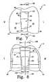
- the posterior cam surface 34 of the spine 30is concave in the sagital plane (see FIG. 3 ) and is convex in the transverse plane (see FIG. 2 ).
- the posterior cam surface 34 of the spine 30bows outwardly posteriorly to define a convex superior edge 60 of the posterior surface 34 of the spine 30 and a convex inferior edge 62 of the posterior surface 34 of the spine 30.
- this posterior bowing of the posterior surface 34 of the spine 30 in the transverse planealso facilitates axial rotation of the femoral component 14 relative to the tibial bearing 12 during flexion as the spine 30 of the tibial bearing 12 interacts with a posterior cam 64 of the femoral component 14.
- the outwardly curved posterior surface 34 of the spine 30may operate to prevent edge loading during axial rotation of the femoral component 14 relative to the tibial bearing 12.
- the medial condylar bearing surface 24 and the lateral condylar bearing surface 26 of the platform 16are concavely curved in the sagittal plane.
- the lateral condylar bearing surface 26is less constrained in the posterior region of the surface 26 with respect to the medial condylar bearing surface 24.
- the medial bearing surface 24 in the sagittal planemay be defined by a first radius of curvature 70.
- the posterior half of the medial bearing surface 24 in the sagittal planemay be defined by a second radius of curvature 72.
- a lateral medial surface 24can be defined by a single radius of curvature or by any suitable number of radii of curvature. As shown, the second radius of curvature 72 is smaller than the first radius of curvature 70. However, the anterior and posterior portions of the medial bearing surface can have any suitable radii of curvature.
- the lateral bearing surface 26is defined by a third radius of curvature 74 in the sagital plane.
- the posterior and anterior half of the lateral bearing surface 26 in the sagittal planeare defined by the same radius of curvature 74.
- the tibial bearingcan have a lateral bearing surface which defines multiple radii of curvature.
- the second, posterior radius of curvature 72 of the posterior half of the medial bearing surface 24is smaller than the third, posterior radius of curvature of the posterior half of the lateral bearing surface 26.
- the third radius of curvature 74may be greater than, less than, or generally equal to the first radius of curvature 70 of the medial bearing surface 24.
- the radius of curvature 74exceeds the radius of curvature 70 by at least 0.5 mm.
- the posterior half of the lateral bearing surface 26can have any suitable radius of curvature greater than the radius of curvature of the posterior half of the medial bearing surface 24. Accordingly, the posterior region of the medial bearing surface 24 is more constrained than a posterior region of the lateral bearing surface 26. As such, the less constrained posterior region of the lateral bearing surface 26 facilitates outward axial rotation of the femoral component 14 in deep or late flexion, as is discussed in greater detail below.
- the femoral component 14is configured to be coupled to a surgically-prepared surface of the distal end of a patient's femur (not shown).
- the femoral component 14may be secured to the patient's femur via use of bone adhesive or other attachment means.
- the femoral component 12is formed from a metallic material such as cobalt-chromium or titanium, but may be formed from other materials, such as a ceramic material, a polymer material, a bio-engineered material, or the like, in other embodiments.
- the femoral component 14includes an articulating surface 80 having a pair of spaced-apart medial and lateral condyles 44, 46 having respective medial and lateral condyle surfaces 88, 90.
- the condyles 44, 46replace the natural condyles of the patient's femur and are configured to articulate on the corresponding bearing surfaces 24, 26 of the platform 16 of the tibial bearing 12.
- the condyles 44, 46are spaced-apart to define an intercondylar notch or recess 82 between them.
- the posterior cam 64is positioned in the intracondyle notch 82.
- the posterior cam 64is located toward the posterior side of the femoral component 14 and includes a cam surface 87 configured to engage or otherwise contact the posterior cam surface 34 of spine 30 of the tibial bearing 12 during flexion as described in more detail below.
- the posterior cam surface 87 of the femoral componentis concavely curved in the medial-lateral direction as shown in FIG. 7 .
- the posterior cam surface 34 of the spine 30is convex in the traverse plane as shown in FIG. 4 .
- the radius of curvature of the cam surfaces 87, 34may be dependent upon a number of criteria such as, for example, the size of the prosthesis, the shape or geometry of the articulating surface of the spine 30 of the tibial implant 12, and the shape or geometry of the articulating surface of the cam 64.
- the intercondylar notch 82is defined by a cam box 92.
- the cam box 92includes an inner medial wall 96, which is connected to a lateral edge of the medial condyle 90, and an inner lateral wall 94, which is connected to a medial edge of the lateral condyle 88.
- the cam box 92also includes an anterior wall 86, which may be embodied as an anterior cam in some embodiments. In such embodiments, the anterior cam includes an anterior cam surface 102.
- the cam box 92also includes the posterior cam 64, which forms an inner posterior "wall" of the cam box 92.
- the cam box 92also includes a superior wall 98. As shown, the superior wall 98 includes an aperture 100 extending through it. The aperture 100 is configured to receive a femoral stem (not shown) to be received with in a bore drilled into the femur of a patient. Additionally, as shown in FIG. 7 , the cam box 92 includes an outer medial sidewall 97 and an outer lateral sidewall 95 .
- the cam surface 102may be generally straight in the medial-lateral direction, as shown in Fig. 7 .
- the anterior wallcould provide a curved cam surface as well.
- the cam surface 102 of the anterior cam 86may interact with the anterior surface 32 of the spine 30 of the tibial bearing 12 during extension.
- the femoral componentincludes the cam box 92 having the convex anterior cam 86
- an anterior camcan have another suitable cam surface to interact with the corresponding anterior surface of the spine of the tibial bearing.
- a cam boxcan be used which does not have an anterior cam. In other words, a cam box can be used which has only a posterior cam.
- the inner medial and lateral sidewalls 96, 94 of the cam box 92are tapered in the transverse plane.
- the sidewalls 94, 96taper toward each other from the anterior side of the femoral component 14 to the posterior side of the femoral component 14.
- the medial sidewall 96is angled with respect to a longitudinal axis 104 of the cam box 92 of the femoral component 14.
- the lateral sidewall 94is similarly angled with respect to the longitudinal axis 104 of the cam box 92 of the femoral component 14.
- the cam box 92has a posterior width 106 and an anterior width 108.
- the posterior width 106may be equal to a width of the posterior cam 64 between the medial sidewall 96 and the lateral sidewall 94.
- the anterior width 108may be equal to a width of the anterior wall 86 between the medial sidewall 96 and the lateral sidewall 94.
- the anterior width 108is greater than the posterior width 106.
- the anterior width 108may exceed the posterior width 106 by 0.5 mm or more.
- a cam boxcan have any suitable posterior width that is less than the anterior width of the cam box.
- the distance between the medial and lateral sidewalls 96, 94 of the cam box 92which is perpendicular to the longitudinal axis 104 of the cam box 92, decreases in a posterior direction.
- a medial-lateral width of the cam box 92 between the sidewalls 94, 96is greater than a medial-lateral width of the spine 30 along similar anterior-posterior positions.
- any width of the cam box 92 taken generally in the anterior half of the cam box 92is wider than the widest portion, i.e., the anterior width 208, of the spine 30. Therefore, the spine 30 generally does not contact the sidewalls 94, 96 of the cam box 92 in early flexion in order to allow the femoral component 14 to remain in a neutral axial position, i.e., having no rotation of the femoral component 14 on the tibial component 12, during early flexion.
- the femoral component 14may remain in a neutral axial position during the first 30° of knee flexion.
- the knee prosthesiscan be constructed so that the femoral component remains in a neutral axial position during any suitable portion of the knee flexion.
- the knee prosthesiscan facilitate the outward axial rotation of the femoral component at some time before or after 30° of knee flexion.
- the femoral component 14articulates on the tibial bearing 12 and is urged to rotate outwardly axially in later flexion.
- the angled and tapered spine 30 of the tibial bearing 12 as well as the tapered cam box 92 of the femoral componentcooperate to promote outward axial rotation of the femoral component 14 on the tibial bearing 12.
- the less constrained posterior portion of the lateral bearing surface 26also promotes such outward axial rotation of the femoral component during flexion.
- cam surface 34 of the spine 30is curved posteriorly in the transverse plane and the posterior cam 64 of the femoral component 12 articulates on the cam surfaces 34 in the transverse plane such that rotation of the femoral component 14 about the spine 30 is further facilitated.
- the angled and tapered spine 30 of the tibial bearing 12cooperates with the tapered cam box 92 during flexion to facilitate axial rotation of the femoral component 14 on the tibial component 12, as shown in FIGS. 11 and 12 .
- the spine 30is positioned within the intercondylar notch 82, which is substantially defined by the cam box 92, of the femoral component 14.
- the cam box 92is sufficiently wide to allow the femoral component 14 to stay in a neutral axial position, i.e., having zero degrees of rotation, relative to the tibial bearing 12, during early knee flexion. For example, as shown in FIGS.
- the femoral component 14is in an axial neutral position at zero degrees of flexion. This axially neutral position is maintained throughout approximately the first 30° of flexion, as noted above.
- the cam box 92is wide enough to prevent the spine 30 from engaging the sidewalls 94, 96 of the cam box 92 during early flexion.
- the sidewalls 94, 96 of the cam box 92begin to engage with the sidewalls 36, 38 of the spine 30.
- the angled spine 30interacts with the cam box 92 to guide the femoral component 14 and axially rotate the femoral component 14 outwardly on the tibial bearing 12.
- the tapered sidewalls 36, 38 of the spine 30 and the tapered sidewalls 94, 96 of the cam box 92cooperate with each other to suitably accommodate the angled spine 30.
- the angled spine 30facilitates rotation of the femoral component 14 outwardly, or in a generally counter-clockwise direction 120, as shown in FIG. 11 , during later flexion of the knee.
- the sidewalls 94, 96 of the cam box 92 and the sidewalls 36, 38 of the spine 30continue to engage each other resulting in a gradually increased axial rotation of the femoral component 14.
- this processis facilitated by the less-constrained posterior portion of the lateral bearing surface 26 of the tibial bearing 12.
- the amount of rotation between the femoral component 14 and the tibial bearing 12 during flexionmaybe adjusted based on the degree of the angle 47 of the spine 30 between the centerline axis of the tibial bearing 45 and the centerline axis of the spine 42. For example, an increased amount of rotation of the femoral component 14 on the tibial bearing 12 may be obtained by increasing the angle 47 of the spine 30.
- the radii of curvature of the medial and lateral bearing surfaces 24, 26 of the tibial bearing 12further cooperate with the femoral component 14 to promote the outward axial rotation of the femoral component 14 on the tibial component 12 during flexion.
- the posterior portion of the lateral bearing surface 26is less constrained than the posterior portion of the medial bearing surface 24.
- the posterior radius of curvature 74 of the lateral bearing surface 26is greater than the posterior radius of curvature 72 of the medial bearing surface 26, thus providing a less constrained posterior bearing surface 26.
- the lateral condyle 46 of the femoral component 14is less constrained within the lateral bearing surface 26 of the tibial bearing 12 when the lateral condyle 46 is engaged with the posterior portion of the lateral bearing surface 26. Accordingly, therefore, the lateral condyle 46 of the femoral component 14 is able to move posteriorly on the lateral bearing surface 26, as shown in deep flexion in FIGS. 11 and 12 , to promote the outward axial rotation of the femoral component 14.
- the femoral component 14 and the tibial bearing 12are configured such that the posterior cam 64 of the femoral component 14 contacts the spine 30 of the tibial bearing 12 during flexion.
- the concave cam surface 87 of the posterior cam 64 of the femoral component 14contacts the convex cam surface 34 of the spine 30. Accordingly, the interaction between the cam surfaces 34, 87 allows the femoral component 14 to rotate axially relative to the tibial bearing 12 during flexion.
- the radius of curvature in the medial-lateral direction of the concave cam surface 87may be substantially equal to, greater than, or less than the radius of curvature in the transverse plane of the convex cam surface 34 of the spine 30.
- the concave cam surface 87 of the posterior cam 64operates to increase the contact area between the posterior surface 34 of the spine 30 and the cam 64. This increase in contact area may decrease the stress between the cam surfaces 34, 87 during axial rotation of the femoral component 14 relative to the tibial bearing 12. Further, the amount of rotation between the femoral component 14 and the tibial bearing 14 during flexion may be adjusted based on the radius of curvatures in the transverse plane of the cam surfaces 34, 87.
- an increased amount of rotation during flexion of the orthopaedic prosthesismay be obtained by decreasing the radius of curvature in the transverse plane of the convex cam surface 87.
- the cam surface 87 of the posterior cam 64is curved posteriorly, the cam surface 87 may also be substantially planar in the medial-lateral direction in some embodiments.
- the posterior cam 64 of the femoral component 14When the orthopaedic prosthesis 10 is extended, or otherwise not in flexion (e.g., a neutral position of about zero degrees flexion), the posterior cam 64 of the femoral component 14 is not in contact with the spine 30 of the tibial bearing 12. However, late flexion the posterior cam 64 of the femoral component 14 contacts the spine 30 of the tibial bearing 12. For example, in some embodiments, the posterior cam 64 may engage the spine 30 at approximately 70° of flexion. As noted above, during late or deep flexion of the orthopaedic prosthesis 10, the convex cam surface 34 of the spine 30 maintains contact with the concave cam surface 87 of the femoral component 14. It should be appreciated that contact between the posterior cam 64 and the spine 30 is maintained during late flexion.
- contact between the concave cam surface 87 of the posterior cam 64 of the femoral component 14 and the convex cam surface 34 of the spine 30 during late flexionmay facilitate rollback of the femoral component 14 on the platform 16 of the tibial bearing 12.
- the femoral component 14may rotate about the spine 30 in the generally counter-clockwise or outward axial direction in the transverse plane as indicated by arrow 120 in FIG. 11 .
- the amount of rotation between the femoral component 14 and the tibial bearing 12 during flexionmay be adjusted based on the radius of curvatures in the transverse plane of the cam surfaces 34, 87.
- the amount of axial rotation of the femoral component 14 relative to the tibial bearing 12is substantially dependent upon the spine angle 47 and the interaction between the sidewalls 36, 38 of the spine 30 and the sidewalls 94, 96 of the cam box 92.
Landscapes
- Health & Medical Sciences (AREA)
- Orthopedic Medicine & Surgery (AREA)
- Physical Education & Sports Medicine (AREA)
- Cardiology (AREA)
- Oral & Maxillofacial Surgery (AREA)
- Transplantation (AREA)
- Engineering & Computer Science (AREA)
- Biomedical Technology (AREA)
- Heart & Thoracic Surgery (AREA)
- Vascular Medicine (AREA)
- Life Sciences & Earth Sciences (AREA)
- Animal Behavior & Ethology (AREA)
- General Health & Medical Sciences (AREA)
- Public Health (AREA)
- Veterinary Medicine (AREA)
- Prostheses (AREA)
Abstract
Description
- The present invention relates to orthopaedic prostheses for use in knee replacement surgery.
- Joint arthroplasty is a well-known surgical procedure by which a diseased and/or damaged natural joint is replaced by a prosthetic joint. A typical knee prosthesis includes a tibial tray, a femoral component, and a polymer insert or bearing positioned between the tibial tray and the femoral component. A knee prosthesis is generally designed to duplicate the natural movement of the patient's joint. However, depending on the severity of the damage to the patient's joint, orthopaedic prostheses of varying mobility may be used. For example, in some patients, the posterior cruciate ligament may be damaged, deficient, or removed during the orthopaedic surgical procedure. In such cases, a posterior stabilized knee orthopaedic prosthesis, which typically restricts or limits the posterior movement of the tibia relative to the femur, may be used.
EP-A-1591082 discloses a knee joint prosthesis which includes a post on the tibial component and a cam on the femoral component, which are shaped so that the femoral component is turned outwardly when the cam comes into contact with the post.- The present invention provides a knee joint prosthesis assembly as defined in claim 1.
- Preferably, the angle defined between the longitudinal axis of the spine and the centerline axis of the platform is greater than about 5°, more preferably from 10° to 15°, for example about 8°.
- The posterior half of the medial condylar bearing surface may have a first radius of curvature in the sagittal plane and the posterior half of the lateral bearing surface may have a second radius of curvature in the sagittal plane. The second radius of curvature may be greater than the first radius of curvature.
- The spine includes a posterior cam surface. The posterior cam surface may be convex in the transverse plane. Additionally, the posterior cam surface is concave in the sagittal plane.
- The platform may include an anterior rim. The spine includes a medial sidewall and a lateral sidewall. The spine may have a length when viewed in the transverse plane that is defined by a first line segment extending from a medial-lateral centre point of the posterior cam surface of the spine to a medial-lateral centre point of the anterior rim of the platform. The spine may have a first width defined by a second line segment orthogonal to and bisecting the first line segment, the second line segment extending from the medial sidewall to the lateral sidewall of the spine. The spine may have a second width defined by a third line segment orthogonal to the first line segment and crossing the first line segment at a point on the first line segment posterior to the second line segment. The third line segment may extend from the medial sidewall to the lateral sidewall of the spine. The first width of the spine being greater than the second width of the spine. For example, the first width is greater than the second width by at least 0.5 mm. In some embodiments the medial sidewall and the lateral sidewall of the spine may taper toward each other in the anterior-posterior direction.
- Embodiments of the invention are described below by way of example with reference to the accompanying drawings, in which:
FIG. 1 is a perspective view of one embodiment of an orthopaedic knee prosthesis;FIG. 2 is a plan view of a tibial bearing of the orthopaedic knee prosthesis ofFIG. 1 ;FIG. 3 is a cross-sectional view of the tibial bearing ofFIG. 2 taken generally along the line 3-3 ofFIG. 1 ;FIG. 4 is an anterior elevational view of the tibial bearing ofFIG. 2 ;FIG. 5 is a cross-sectional view of the tibial bearing ofFIG. 2 taken generally along the line 5-5;FIG. 6 is another cross-sectional view of the tibial bearing ofFIG. 2 taken generally along the line 6-6;FIG. 7 is an inferior elevational view of a femoral component of the orthopaedic knee prosthesis ofFIG. 1 ;FIG. 8 is a superior elevational view of the femoral component ofFIG. 7 ;FIG. 9 is a schematic diagram of a superior plan view of the femoral component and tibial bearing of the orthopaedic knee prosthesis ofFIG. 1 in an assembled configuration and positioned at about 0° of flexion;FIG. 10 is a side elevational view of the assembled orthopaedic knee prosthesis ofFIG. 9 ;FIG. 11 is a schematic diagram of a superior plan view of the assembled orthopaedic knee prosthesis ofFIG. 9 positioned in deep flexion; andFIG. 12 is a side elevational view of the assembled orthopaedic knee prosthesis ofFIG. 11 .- Terms representing anatomical references, such as anterior, posterior, medial, lateral, superior, inferior, etcetera, may be used throughout this disclosure in reference to both the orthopaedic implants described herein and a patient's natural anatomy. Such terms have well-understood meanings in both the study of anatomy and the field of orthopaedics. Use of such anatomical reference terms in the specification and claims is intended to be consistent with their well-understood meanings unless noted otherwise.
- Referring to the drawings,
FIG. 1 shows a posterior stabilizedorthopaedic knee prosthesis 10 which includes a tibial insert or bearing 12, afemoral component 14, and, in some embodiments, a tibial tray (not shown). Thefemoral component 14 is configured to articulate with the tibial bearing 12 during use. In particular, theknee prosthesis 10 is configured to promote external axial rotation of thefemoral component 14 with respect to the tibial bearing 12 during flexion of a patient's knee as discussed in more detail below. - The
orthopaedic knee prosthesis 10 is shown in the drawings is a left knee prosthesis, which is configured to replace the left knee of a patient. However, in other embodiments, theorthopaedic knee prosthesis 10 may be embodied as a right knee prosthesis configured to replace a right knee of a patient. Accordingly, the concepts and features of the invention are applicable to both left and right knee orthopaedic prostheses. - The tibial bearing 12 is formed from a polymer material such as ultra-high molecular weight polyethylene (UHMWPE), but may be formed from other materials, such as a ceramic material, a metallic material, a bio-engineered material, or the like, in other embodiments. Additionally, in the described embodiment, the tibial bearing 12 is embodied as a fixed tibial bearing which may be limited or restricted from rotating relative to the tibial tray.
- As shown in
FIG. 1 , the tibial bearing 12 includes aplatform 16 having an upper bearingsurface 18 and a bottom surface 20. As shown, thebearing 12 may also include other devices or features to secure the tibial bearing 12 to the tibial tray in a non-rotating configuration. The upper bearingsurface 18 of the tibial bearing 12 includes a medial bearingsurface 24 and a lateral bearingsurface 26. The medial and lateral bearingsurfaces lateral condyles femoral component 14, as is discussed in greater detail below. As such, thebearing surfaces - A
spine 30 of thebearing 12 extends upwardly from theplatform 16 and is positioned between thebearing surfaces spine 30 includes ananterior surface 32, aposterior cam surface 34, amedial sidewall 36, and alateral sidewall 38. Thespine 30 further includes asuperior surface 40. As shown inFIG. 2 , thespine 30 is angled toward the medial bearingsurface 24 of theplatform 16 as thespine 30 extends posteriorly. In other words, thespine 30 is angled medially from theanterior surface 32 to theposterior cam surface 34 of thespine 30 in the transverse plane. As such, alongitudinal axis 42 of thespine 30, when viewed in the transverse plane is angled with respect to acenterline axis 45 of theplatform 16 extending in the anterior-posterior direction. Thelongitudinal axis 42 and thecenterline axis 45 define an angle 47 between them. Thespine 30 can be configured such that the angle 47 is greater than about 5°. For example, in one particular embodiment, the angle 47 is about 8°. Additionally, in another particular embodiment, the angle 47 is from about 10 to about 15°. As is discussed in greater detail below, the angle 47 of thespine 30 facilitates outward axial rotation of thefemoral component 14 relative to thetibial bearing 12. In particular, the amount of axial rotation of thefemoral component 14 is related to the degree or angle 47 of thespine 30. In other words, an increased amount of rotation during flexion of the orthopaedic prosthesis may be obtained by increasing the angle 47 whereas a decreased amount of rotation during flexion may be obtained by decreasing the angle 47. - Referring again to
FIG. 2 , thespine 30 of thetibial bearing 12 is also tapered in the anterior-posterior direction in the transverse plane. In other words, the medial and lateral surfaces, or sidewalls, 36, 38 of thespine 30 converge toward each other from theanterior surface 32 of thespine 30 to theposterior surface 34 of thespine 30. For example, in some embodiments, thesurface spine 30. - As such, the
spine 30 may have a substantially decreasing width in the anterior-posterior direction. That is, thespine 30 may have an anterior width that is greater than a posterior width. For example, in one embodiment, thespine 30 may have a length when viewed in the transverse plane defined by aline segment 200 extending from acentre point 202 of theposterior cam surface 34 to a centre point 204 of ananterior rim 206 of theplatform 16. Thespine 30 also has an anterior width defined by aline segment 208 extending from thelateral sidewall 38 to themedial sidewall 36. Theline segment 208 is orthogonal to and bisects theline segment 200. Thespine 30 also has an posterior width (with respect as to the anterior width) defined by aline segment 210 extending from thelateral sidewall 38 to themedial sidewall 36. Theline segment 210 is orthogonal to theline segment 200 and is positioned posteriorly with respect to theline segment 208. In some embodiments, the anterior width of thespine 30 is greater than the posterior width of thespine 30. That is, the length of theline segment 208 is greater than the length of theline segment 210. For example, in some embodiments, theline segment 208 may have a length that is greater than the length of theline segment 210 by at least 0.1 mm. As such, in some embodiments, thespine 30 may be angled and tapered in the anterior-to-posterior direction. - Referring now to
FIGS. 2 to 4 , theposterior cam surface 34 of thespine 30 is concave in the sagital plane (seeFIG. 3 ) and is convex in the transverse plane (seeFIG. 2 ). In other words, as shown inFIG. 2 , theposterior cam surface 34 of thespine 30 bows outwardly posteriorly to define a convexsuperior edge 60 of theposterior surface 34 of thespine 30 and a convexinferior edge 62 of theposterior surface 34 of thespine 30. As is discussed in greater detail below, this posterior bowing of theposterior surface 34 of thespine 30 in the transverse plane also facilitates axial rotation of thefemoral component 14 relative to thetibial bearing 12 during flexion as thespine 30 of thetibial bearing 12 interacts with aposterior cam 64 of thefemoral component 14. The outwardly curvedposterior surface 34 of thespine 30 may operate to prevent edge loading during axial rotation of thefemoral component 14 relative to thetibial bearing 12. - Referring now to
FIGS. 5 and 6 , the medialcondylar bearing surface 24 and the lateralcondylar bearing surface 26 of theplatform 16 are concavely curved in the sagittal plane. In some embodiments, the lateralcondylar bearing surface 26 is less constrained in the posterior region of thesurface 26 with respect to the medialcondylar bearing surface 24. For example, as shown inFIG. 5 , themedial bearing surface 24 in the sagittal plane may be defined by a first radius of curvature 70. Additionally, in some embodiments, the posterior half of themedial bearing surface 24 in the sagittal plane may be defined by a second radius ofcurvature 72. While two radii ofcurvature 70, 72 are incorporated into the described component, a lateralmedial surface 24 can be defined by a single radius of curvature or by any suitable number of radii of curvature. As shown, the second radius ofcurvature 72 is smaller than the first radius of curvature 70. However, the anterior and posterior portions of the medial bearing surface can have any suitable radii of curvature. - As shown in
FIG. 6 , thelateral bearing surface 26 is defined by a third radius of curvature 74 in the sagital plane. As shown, the posterior and anterior half of thelateral bearing surface 26 in the sagittal plane are defined by the same radius of curvature 74. However, the tibial bearing can have a lateral bearing surface which defines multiple radii of curvature. As shown, the second, posterior radius ofcurvature 72 of the posterior half of themedial bearing surface 24 is smaller than the third, posterior radius of curvature of the posterior half of thelateral bearing surface 26. The third radius of curvature 74 may be greater than, less than, or generally equal to the first radius of curvature 70 of themedial bearing surface 24. For example, in one embodiment, the radius of curvature 74 exceeds the radius of curvature 70 by at least 0.5 mm. However, the posterior half of thelateral bearing surface 26 can have any suitable radius of curvature greater than the radius of curvature of the posterior half of themedial bearing surface 24. Accordingly, the posterior region of themedial bearing surface 24 is more constrained than a posterior region of thelateral bearing surface 26. As such, the less constrained posterior region of thelateral bearing surface 26 facilitates outward axial rotation of thefemoral component 14 in deep or late flexion, as is discussed in greater detail below. - Looking now to
FIGS. 7 and 8 , thefemoral component 14 is configured to be coupled to a surgically-prepared surface of the distal end of a patient's femur (not shown). Thefemoral component 14 may be secured to the patient's femur via use of bone adhesive or other attachment means. Thefemoral component 12 is formed from a metallic material such as cobalt-chromium or titanium, but may be formed from other materials, such as a ceramic material, a polymer material, a bio-engineered material, or the like, in other embodiments. - The
femoral component 14 includes an articulatingsurface 80 having a pair of spaced-apart medial andlateral condyles condyles platform 16 of thetibial bearing 12. - The
condyles recess 82 between them. Theposterior cam 64 is positioned in theintracondyle notch 82. Theposterior cam 64 is located toward the posterior side of thefemoral component 14 and includes acam surface 87 configured to engage or otherwise contact theposterior cam surface 34 ofspine 30 of thetibial bearing 12 during flexion as described in more detail below. - As shown, the
posterior cam surface 87 of the femoral component is concavely curved in the medial-lateral direction as shown inFIG. 7 . Theposterior cam surface 34 of thespine 30 is convex in the traverse plane as shown inFIG. 4 . The radius of curvature of the cam surfaces 87, 34 may be dependent upon a number of criteria such as, for example, the size of the prosthesis, the shape or geometry of the articulating surface of thespine 30 of thetibial implant 12, and the shape or geometry of the articulating surface of thecam 64. - The
intercondylar notch 82 is defined by acam box 92. Thecam box 92 includes an innermedial wall 96, which is connected to a lateral edge of themedial condyle 90, and an innerlateral wall 94, which is connected to a medial edge of thelateral condyle 88. Thecam box 92 also includes ananterior wall 86, which may be embodied as an anterior cam in some embodiments. In such embodiments, the anterior cam includes ananterior cam surface 102. Thecam box 92 also includes theposterior cam 64, which forms an inner posterior "wall" of thecam box 92. - The
cam box 92 also includes asuperior wall 98. As shown, thesuperior wall 98 includes anaperture 100 extending through it. Theaperture 100 is configured to receive a femoral stem (not shown) to be received with in a bore drilled into the femur of a patient. Additionally, as shown inFIG. 7 , thecam box 92 includes an outermedial sidewall 97 and an outerlateral sidewall 95 . - In embodiments in which the
anterior wall 86 is embodied as an anterior cam, thecam surface 102 may be generally straight in the medial-lateral direction, as shown inFig. 7 . However, the anterior wall could provide a curved cam surface as well. As shown, thecam surface 102 of theanterior cam 86 may interact with theanterior surface 32 of thespine 30 of thetibial bearing 12 during extension. Although the femoral component includes thecam box 92 having the convexanterior cam 86, an anterior cam can have another suitable cam surface to interact with the corresponding anterior surface of the spine of the tibial bearing. Further, a cam box can be used which does not have an anterior cam. In other words, a cam box can be used which has only a posterior cam. - Referring again to
FIGS. 7 and 8 , the inner medial andlateral sidewalls cam box 92 are tapered in the transverse plane. In particular, thesidewalls femoral component 14 to the posterior side of thefemoral component 14. Accordingly, themedial sidewall 96 is angled with respect to alongitudinal axis 104 of thecam box 92 of thefemoral component 14. Thelateral sidewall 94 is similarly angled with respect to thelongitudinal axis 104 of thecam box 92 of thefemoral component 14. - As shown, the
cam box 92 has aposterior width 106 and ananterior width 108. Theposterior width 106 may be equal to a width of theposterior cam 64 between themedial sidewall 96 and thelateral sidewall 94. Similarly, theanterior width 108 may be equal to a width of theanterior wall 86 between themedial sidewall 96 and thelateral sidewall 94. As shown inFIGS. 7 and 8 , theanterior width 108 is greater than theposterior width 106. For example, in some embodiments, theanterior width 108 may exceed theposterior width 106 by 0.5 mm or more. However, a cam box can have any suitable posterior width that is less than the anterior width of the cam box. Furthermore, similar to thespine 30, the distance between the medial andlateral sidewalls cam box 92, which is perpendicular to thelongitudinal axis 104 of thecam box 92, decreases in a posterior direction. - As shown, a medial-lateral width of the
cam box 92 between the sidewalls 94, 96 is greater than a medial-lateral width of thespine 30 along similar anterior-posterior positions. In particular, any width of thecam box 92 taken generally in the anterior half of thecam box 92 is wider than the widest portion, i.e., theanterior width 208, of thespine 30. Therefore, thespine 30 generally does not contact thesidewalls cam box 92 in early flexion in order to allow thefemoral component 14 to remain in a neutral axial position, i.e., having no rotation of thefemoral component 14 on thetibial component 12, during early flexion. For example, in some embodiments, thefemoral component 14 may remain in a neutral axial position during the first 30° of knee flexion. However, the knee prosthesis can be constructed so that the femoral component remains in a neutral axial position during any suitable portion of the knee flexion. In other words, the knee prosthesis can facilitate the outward axial rotation of the femoral component at some time before or after 30° of knee flexion. - As stated above, the
femoral component 14 articulates on thetibial bearing 12 and is urged to rotate outwardly axially in later flexion. As noted above, the angled andtapered spine 30 of thetibial bearing 12 as well as the taperedcam box 92 of the femoral component cooperate to promote outward axial rotation of thefemoral component 14 on thetibial bearing 12. Further, the less constrained posterior portion of thelateral bearing surface 26 also promotes such outward axial rotation of the femoral component during flexion. Additionally, thecam surface 34 of thespine 30 is curved posteriorly in the transverse plane and theposterior cam 64 of thefemoral component 12 articulates on the cam surfaces 34 in the transverse plane such that rotation of thefemoral component 14 about thespine 30 is further facilitated. - For example, the angled and
tapered spine 30 of thetibial bearing 12 cooperates with the taperedcam box 92 during flexion to facilitate axial rotation of thefemoral component 14 on thetibial component 12, as shown inFIGS. 11 and 12 . As shown, thespine 30 is positioned within theintercondylar notch 82, which is substantially defined by thecam box 92, of thefemoral component 14. As noted above, thecam box 92 is sufficiently wide to allow thefemoral component 14 to stay in a neutral axial position, i.e., having zero degrees of rotation, relative to thetibial bearing 12, during early knee flexion. For example, as shown inFIGS. 9 and 10 , thefemoral component 14 is in an axial neutral position at zero degrees of flexion. This axially neutral position is maintained throughout approximately the first 30° of flexion, as noted above. In other words, thecam box 92 is wide enough to prevent thespine 30 from engaging thesidewalls cam box 92 during early flexion. - At approximately 30° of flexion, the
sidewalls cam box 92 begin to engage with thesidewalls spine 30. As such, theangled spine 30 interacts with thecam box 92 to guide thefemoral component 14 and axially rotate thefemoral component 14 outwardly on thetibial bearing 12. The taperedsidewalls spine 30 and the taperedsidewalls cam box 92 cooperate with each other to suitably accommodate theangled spine 30. - Accordingly, the
angled spine 30 facilitates rotation of thefemoral component 14 outwardly, or in a generallycounter-clockwise direction 120, as shown inFIG. 11 , during later flexion of the knee. As the knee continues to flex, thesidewalls cam box 92 and thesidewalls spine 30 continue to engage each other resulting in a gradually increased axial rotation of thefemoral component 14. As noted below, this process is facilitated by the less-constrained posterior portion of thelateral bearing surface 26 of thetibial bearing 12. The amount of rotation between thefemoral component 14 and thetibial bearing 12 during flexion maybe adjusted based on the degree of the angle 47 of thespine 30 between the centerline axis of thetibial bearing 45 and the centerline axis of thespine 42. For example, an increased amount of rotation of thefemoral component 14 on thetibial bearing 12 may be obtained by increasing the angle 47 of thespine 30. - As noted above, the radii of curvature of the medial and lateral bearing surfaces 24, 26 of the
tibial bearing 12 further cooperate with thefemoral component 14 to promote the outward axial rotation of thefemoral component 14 on thetibial component 12 during flexion. For example, the posterior portion of thelateral bearing surface 26 is less constrained than the posterior portion of themedial bearing surface 24. As discussed above, the posterior radius of curvature 74 of thelateral bearing surface 26 is greater than the posterior radius ofcurvature 72 of themedial bearing surface 26, thus providing a less constrainedposterior bearing surface 26. During later flexion, therefore, thelateral condyle 46 of thefemoral component 14 is less constrained within thelateral bearing surface 26 of thetibial bearing 12 when thelateral condyle 46 is engaged with the posterior portion of thelateral bearing surface 26. Accordingly, therefore, thelateral condyle 46 of thefemoral component 14 is able to move posteriorly on thelateral bearing surface 26, as shown in deep flexion inFIGS. 11 and 12 , to promote the outward axial rotation of thefemoral component 14. - As further noted above, the
femoral component 14 and thetibial bearing 12 are configured such that theposterior cam 64 of thefemoral component 14 contacts thespine 30 of thetibial bearing 12 during flexion. In particular, during flexion, theconcave cam surface 87 of theposterior cam 64 of thefemoral component 14 contacts theconvex cam surface 34 of thespine 30. Accordingly, the interaction between the cam surfaces 34, 87 allows thefemoral component 14 to rotate axially relative to thetibial bearing 12 during flexion. In some embodiments, the radius of curvature in the medial-lateral direction of theconcave cam surface 87 may be substantially equal to, greater than, or less than the radius of curvature in the transverse plane of theconvex cam surface 34 of thespine 30. As shown, theconcave cam surface 87 of theposterior cam 64 operates to increase the contact area between theposterior surface 34 of thespine 30 and thecam 64. This increase in contact area may decrease the stress between the cam surfaces 34, 87 during axial rotation of thefemoral component 14 relative to thetibial bearing 12. Further, the amount of rotation between thefemoral component 14 and thetibial bearing 14 during flexion may be adjusted based on the radius of curvatures in the transverse plane of the cam surfaces 34, 87. For example, an increased amount of rotation during flexion of the orthopaedic prosthesis may be obtained by decreasing the radius of curvature in the transverse plane of theconvex cam surface 87. As shown, while thecam surface 87 of theposterior cam 64 is curved posteriorly, thecam surface 87 may also be substantially planar in the medial-lateral direction in some embodiments. - When the
orthopaedic prosthesis 10 is extended, or otherwise not in flexion (e.g., a neutral position of about zero degrees flexion), theposterior cam 64 of thefemoral component 14 is not in contact with thespine 30 of thetibial bearing 12. However, late flexion theposterior cam 64 of thefemoral component 14 contacts thespine 30 of thetibial bearing 12. For example, in some embodiments, theposterior cam 64 may engage thespine 30 at approximately 70° of flexion. As noted above, during late or deep flexion of theorthopaedic prosthesis 10, theconvex cam surface 34 of thespine 30 maintains contact with theconcave cam surface 87 of thefemoral component 14. It should be appreciated that contact between theposterior cam 64 and thespine 30 is maintained during late flexion. - For example, contact between the
concave cam surface 87 of theposterior cam 64 of thefemoral component 14 and theconvex cam surface 34 of thespine 30 during late flexion may facilitate rollback of thefemoral component 14 on theplatform 16 of thetibial bearing 12. Furthermore, as noted above, during flexion, thefemoral component 14 may rotate about thespine 30 in the generally counter-clockwise or outward axial direction in the transverse plane as indicated byarrow 120 inFIG. 11 . The amount of rotation between thefemoral component 14 and thetibial bearing 12 during flexion may be adjusted based on the radius of curvatures in the transverse plane of the cam surfaces 34, 87. However, as noted above, the amount of axial rotation of thefemoral component 14 relative to thetibial bearing 12 is substantially dependent upon the spine angle 47 and the interaction between the sidewalls 36, 38 of thespine 30 and thesidewalls cam box 92. - Many features of the prosthesis of the invention cooperate to facilitate outward axial rotation of the
femoral component 14 on thetibial bearing 12. While these features are shown and described on acommon prosthesis 10, the knee prosthesis might have only one or more of the above-disclosed features which promote the outward axial rotation of thefemoral component 14 and which cooperate with and accommodate such features.
Claims (7)
- A knee joint prosthesis assembly which comprises a tibial bearing (12) and a femoral component (14), in which the tibial bearing comprises:a platform (16) having a medial condylar bearing surface (24) and a lateral condylar bearing surface (26), the platform having a centerline axis (45) defined in the anterior-posterior direction when viewed in the transverse plane, anda spine (30) extending upwardly from the platform between the medial bearing surface and the lateral bearing surface, the spine having a longitudinal axis (42) that is arranged at a fixed non-zero angle with respect to the centerline axis of the platform, and having medial and lateral side walls (36, 38) and a posterior cam surface (34),and in which the femoral component comprises:spaced apart medial and lateral condyles (44, 46), each having a condyle surface (88, 90) for articulation on the medial and lateral condylar bearing surfaces respectively on the platform of the tibial bearing,a cam box (92) between the medial and lateral condyles defined by an inner medial wall (96) and an inner lateral wall (94) and an inner posterior wall which is provided by a posterior cam (64) at the posterior side of the femoral component having a cam surface (87) which engages the posterior cam surface of the spine during flexion of the knee when in use,characterisedinthat the spine is tapered inwardly in a direction from its anterior end to its posterior end, and the medial and lateral walls of the cam box taper towards one another from the anterior side to the posterior side of the femoral component so that the medial and lateral walls of the cam box do not contact the sidewalls of the spine when the knee is not flexed and in early flexion, and then the medial and lateral walls of the cam box contact the sidewalls of the spine at later flexion to cause the femoral component to rotate outwardly on the tibial bearing.
- The knee joint prosthesis assembly of claim 1, in which an angle defined between the longitudinal axis (45) of the spine (30) and the centerline axis (42) of the platform (16) is greater than about 5°, preferably between 10° and 15°.
- The knee joint prosthesis assembly of claim 1, in which:(i) the posterior half of the medial condylar bearing surface (24) has a first radius of curvature (70) in the sagittal plane, and(ii) the posterior half of the lateral bearing surface (26) has a second radius of curvature (72) in the sagittal plane that is greater than the first radius of curvature.
- The knee joint prosthesis assembly of claim 1, in which the posterior cam surface (34) is convex in the transverse plane.
- The knee joint prosthesis assembly of claim 4, in which the posterior cam surface (34) is concave in the sagittal plane.
- The knee joint prosthesis assembly of claim 4, in which:(i) the platform (16) includes an anterior rim (206),(ii) the spine (30) has a length when viewed in the transverse plane that is defined by a first line segment (200) extending from a medial-lateral centre point (202) of the posterior cam surface of the spine to a medial-lateral centre point (204) of the anterior rim of the platform,(iii) the spine has a first width defined by a second line segment (208) orthogonal to and bisecting the first line segment, the second line segment extending from the medial sidewall (36) to the lateral sidewall (38) of the spine,(iv) the spine has a second width defined by a third line segment (210) orthogonal to the first line segment and crossing the first line segment at a point on the first line segment posterior to the second line segment, the third line segment extending from the medial sidewall to the lateral sidewall of the spine, and(v) the first width of the spine is greater than the second width of the spine.
- The knee joint prosthesis assembly of claim 6, in which the first width exceeds the second width by at least 0.5 mm.
Applications Claiming Priority (1)
| Application Number | Priority Date | Filing Date | Title |
|---|---|---|---|
| US12/165,439US8480752B2 (en) | 2008-06-30 | 2008-06-30 | Tibial bearing having increased axial-rotation |
Publications (3)
| Publication Number | Publication Date |
|---|---|
| EP2140838A2 EP2140838A2 (en) | 2010-01-06 |
| EP2140838A3 EP2140838A3 (en) | 2010-02-17 |
| EP2140838B1true EP2140838B1 (en) | 2012-01-18 |
Family
ID=41112488
Family Applications (1)
| Application Number | Title | Priority Date | Filing Date |
|---|---|---|---|
| EP09164242AActiveEP2140838B1 (en) | 2008-06-30 | 2009-06-30 | Tibial bearing for a knee joint prosthesis |
Country Status (8)
| Country | Link |
|---|---|
| US (1) | US8480752B2 (en) |
| EP (1) | EP2140838B1 (en) |
| JP (1) | JP5442335B2 (en) |
| CN (1) | CN101658447B (en) |
| AT (1) | ATE541536T1 (en) |
| AU (1) | AU2009202630B2 (en) |
| DK (1) | DK2140838T3 (en) |
| ES (1) | ES2376966T3 (en) |
Families Citing this family (46)
| Publication number | Priority date | Publication date | Assignee | Title |
|---|---|---|---|---|
| US8029574B2 (en) | 2006-11-07 | 2011-10-04 | Biomedflex Llc | Prosthetic knee joint |
| US8070823B2 (en) | 2006-11-07 | 2011-12-06 | Biomedflex Llc | Prosthetic ball-and-socket joint |
| US8308812B2 (en) | 2006-11-07 | 2012-11-13 | Biomedflex, Llc | Prosthetic joint assembly and joint member therefor |
| US9005307B2 (en) | 2006-11-07 | 2015-04-14 | Biomedflex, Llc | Prosthetic ball-and-socket joint |
| WO2008058205A1 (en) | 2006-11-07 | 2008-05-15 | Biomedflex, Llc | Medical implants |
| US8512413B2 (en) | 2006-11-07 | 2013-08-20 | Biomedflex, Llc | Prosthetic knee joint |
| US20110166671A1 (en) | 2006-11-07 | 2011-07-07 | Kellar Franz W | Prosthetic joint |
| CN102006839B (en)* | 2008-02-18 | 2014-07-23 | 麦克斯外科整形公司 | Total knee replacement prosthesis |
| CA2756226C (en)* | 2009-03-27 | 2017-01-24 | Smith & Nephew Orthopaedics Ag | Artificial knee joint |
| US9095453B2 (en)* | 2009-08-11 | 2015-08-04 | Michael D. Ries | Position adjustable trial systems for prosthetic implants |
| US8496666B2 (en) | 2009-08-11 | 2013-07-30 | Imds Corporation | Instrumentation for mobile bearing prosthetics |
| US8568485B2 (en)* | 2009-08-11 | 2013-10-29 | Imds Corporation | Articulating trials for prosthetic implants |
| US8998997B2 (en) | 2009-08-11 | 2015-04-07 | Michael D. Ries | Implantable mobile bearing prosthetics |
| US8382848B2 (en)* | 2009-08-11 | 2013-02-26 | Imds Corporation | Position adjustable trial systems for prosthetic implants |
| US8764840B2 (en) | 2010-07-24 | 2014-07-01 | Zimmer, Inc. | Tibial prosthesis |
| ES2632995T3 (en) | 2010-07-24 | 2017-09-18 | Zimmer, Inc. | Asymmetric tibia components for a knee prosthesis |
| EP2606856A4 (en)* | 2010-08-19 | 2014-01-22 | Kyocera Medical Corp | Artificial knee joint |
| US8591594B2 (en) | 2010-09-10 | 2013-11-26 | Zimmer, Inc. | Motion facilitating tibial components for a knee prosthesis |
| CN103503050B (en)* | 2010-11-15 | 2017-03-15 | 先进机械技术公司 | Method and apparatus for joint motion simulation |
| US8603101B2 (en) | 2010-12-17 | 2013-12-10 | Zimmer, Inc. | Provisional tibial prosthesis system |
| US8728167B2 (en)* | 2011-01-10 | 2014-05-20 | Howmedica Osteonics Corp. | Bicruciate retaining tibial baseplate design and method of implantation |
| CN103327937B (en)* | 2011-01-27 | 2017-08-08 | 史密夫和内修有限公司 | constrained knee prosthesis |
| EP3308726A3 (en)* | 2011-07-13 | 2018-10-24 | The General Hospital Corporation d/b/a Massachusetts General Hospital | Devices for knee joint replacement with anterior cruciate ligament substitution |
| US20130123931A1 (en)* | 2011-11-14 | 2013-05-16 | Maxx Orthopedics, Inc. | Knee Revision Prosthesis With Progressive Restraint |
| EP3175824B1 (en)* | 2011-11-18 | 2019-01-02 | Zimmer, Inc. | Tibial bearing component for a knee prosthesis with improved articular characteristics |
| ES2585838T3 (en) | 2011-11-21 | 2016-10-10 | Zimmer, Inc. | Tibial base plate with asymmetric placement of fixing structures |
| US9668871B2 (en) | 2011-12-29 | 2017-06-06 | Mako Surgical Corp. | Cruciate-retaining tibial prosthesis |
| IN2014DN07145A (en) | 2012-01-30 | 2015-04-24 | Zimmer Inc | |
| US9925052B2 (en) | 2013-08-30 | 2018-03-27 | Zimmer, Inc. | Method for optimizing implant designs |
| JP6305268B2 (en)* | 2014-08-07 | 2018-04-04 | スミス・アンド・ネフュー・オルソペディクス・アーゲー | Artificial knee joint |
| WO2017053196A1 (en) | 2015-09-21 | 2017-03-30 | Zimmer, Inc. | Prosthesis system including tibial bearing component |
| KR101769125B1 (en) | 2016-02-19 | 2017-08-17 | 주식회사 티제이씨라이프 | Artificial Knee Joint Having Surface Contact Type Protrusion |
| US10231840B2 (en) | 2016-07-27 | 2019-03-19 | Howmedica Osteonics Corp. | Low profile tibial baseplate with fixation members |
| US10675153B2 (en) | 2017-03-10 | 2020-06-09 | Zimmer, Inc. | Tibial prosthesis with tibial bearing component securing feature |
| WO2018208612A1 (en) | 2017-05-12 | 2018-11-15 | Zimmer, Inc. | Femoral prostheses with upsizing and downsizing capabilities |
| US11426282B2 (en) | 2017-11-16 | 2022-08-30 | Zimmer, Inc. | Implants for adding joint inclination to a knee arthroplasty |
| US10835380B2 (en) | 2018-04-30 | 2020-11-17 | Zimmer, Inc. | Posterior stabilized prosthesis system |
| CN108992215B (en)* | 2018-08-14 | 2024-06-07 | 优适医疗科技(苏州)有限公司 | Novel knee joint prosthesis |
| EP3698761B1 (en) | 2019-02-22 | 2021-11-17 | Stryker European Operations Limited | Total ankle prosthesis |
| US11129720B2 (en) | 2019-03-05 | 2021-09-28 | Jonathan P. GARINO | Cruciate replacing artificial knee |
| JP2022524439A (en) | 2019-03-12 | 2022-05-02 | デピュイ・アイルランド・アンリミテッド・カンパニー | Orthopedic system with medial pivot femoral components and inserts |
| AU2020265431B2 (en) | 2019-05-02 | 2025-04-24 | Depuy Ireland Unlimited Company | Orthopaedic implant placement system and method |
| WO2020225676A1 (en) | 2019-05-08 | 2020-11-12 | DePuy Synthes Products, Inc. | Orthopaedic implant system with hinge |
| US11141291B2 (en)* | 2019-06-30 | 2021-10-12 | Depuy Ireland Unlimited Company | Femoral trial components and associated orthopaedic surgical method of use |
| US12083020B2 (en) | 2019-09-10 | 2024-09-10 | Depuy Ireland Unlimited Company | Orthopaedic knee prosthesis system and methods for using same |
| EP4545052A3 (en) | 2020-07-10 | 2025-07-09 | DePuy Ireland Unlimited Company | Medial stabilized orthopaedic knee prosthesis |
Family Cites Families (17)
| Publication number | Priority date | Publication date | Assignee | Title |
|---|---|---|---|---|
| US4959071A (en)* | 1988-02-03 | 1990-09-25 | Biomet, Inc. | Partially stabilized knee prosthesis |
| US5192328A (en)* | 1989-09-29 | 1993-03-09 | Winters Thomas F | Knee joint replacement apparatus |
| US5147405A (en)* | 1990-02-07 | 1992-09-15 | Boehringer Mannheim Corporation | Knee prosthesis |
| US5370699A (en)* | 1993-01-21 | 1994-12-06 | Orthomet, Inc. | Modular knee joint prosthesis |
| US5702458A (en)* | 1994-12-09 | 1997-12-30 | New York Society For The Ruptured And Crippled Maintaining The Hospital For Special Surgery | Joint prosthesis |
| US5964808A (en)* | 1996-07-11 | 1999-10-12 | Wright Medical Technology, Inc. | Knee prosthesis |
| US6325828B1 (en)* | 1997-12-02 | 2001-12-04 | Rose Biomedical Research | Apparatus for knee prosthesis |
| US6080195A (en)* | 1998-07-08 | 2000-06-27 | Johnson & Johnson Professional, Inc. | Rotatable and translatable joint prosthesis with posterior stabilization |
| US6972039B2 (en) | 1999-03-01 | 2005-12-06 | Biomet, Inc. | Floating bearing knee joint prosthesis with a fixed tibial post |
| US20040054416A1 (en) | 2002-09-12 | 2004-03-18 | Joe Wyss | Posterior stabilized knee with varus-valgus constraint |
| JP4148316B2 (en)* | 2002-11-18 | 2008-09-10 | 株式会社神戸製鋼所 | Artificial knee joint |
| ES2465090T3 (en) | 2002-12-20 | 2014-06-05 | Smith & Nephew, Inc. | High performance knee prostheses |
| US6986791B1 (en)* | 2003-04-15 | 2006-01-17 | Biomet Manufacturing Corp. | Knee prosthesis with moveable post |
| FR2854792B1 (en)* | 2003-05-12 | 2005-09-09 | Tornier Sa | GAME OF PROTHETIC ELEMENTS FOR A TIBIAL PROTHETIC SET |
| JP3915989B2 (en) | 2004-03-17 | 2007-05-16 | 徹 勝呂 | Artificial knee joint |
| GB0510194D0 (en)* | 2005-05-19 | 2005-06-22 | Mcminn Derek J W | Knee prosthesis |
| GB0510193D0 (en)* | 2005-05-19 | 2005-06-22 | Mcminn Derek J W | Knee prosthesis |
- 2008
- 2008-06-30USUS12/165,439patent/US8480752B2/enactiveActive
- 2009
- 2009-06-29JPJP2009153358Apatent/JP5442335B2/enactiveActive
- 2009-06-29AUAU2009202630Apatent/AU2009202630B2/ennot_activeCeased
- 2009-06-30ESES09164242Tpatent/ES2376966T3/enactiveActive
- 2009-06-30EPEP09164242Apatent/EP2140838B1/enactiveActive
- 2009-06-30CNCN200910163991.4Apatent/CN101658447B/ennot_activeExpired - Fee Related
- 2009-06-30ATAT09164242Tpatent/ATE541536T1/enactive
- 2009-06-30DKDK09164242.1Tpatent/DK2140838T3/enactive
Also Published As
| Publication number | Publication date |
|---|---|
| US20090326668A1 (en) | 2009-12-31 |
| JP2010012262A (en) | 2010-01-21 |
| AU2009202630A1 (en) | 2010-01-14 |
| ES2376966T3 (en) | 2012-03-21 |
| DK2140838T3 (en) | 2012-04-10 |
| EP2140838A3 (en) | 2010-02-17 |
| CN101658447A (en) | 2010-03-03 |
| JP5442335B2 (en) | 2014-03-12 |
| CN101658447B (en) | 2014-10-29 |
| AU2009202630B2 (en) | 2015-08-06 |
| ATE541536T1 (en) | 2012-02-15 |
| US8480752B2 (en) | 2013-07-09 |
| EP2140838A2 (en) | 2010-01-06 |
Similar Documents
| Publication | Publication Date | Title |
|---|---|---|
| EP2140838B1 (en) | Tibial bearing for a knee joint prosthesis | |
| EP2143403B1 (en) | Knee Prosthesis | |
| US8206451B2 (en) | Posterior stabilized orthopaedic prosthesis | |
| EP2726021B1 (en) | Posterior stabilized orthopaedic prosthesis assembly | |
| US20180064543A1 (en) | Knee prosthesis assembly having proportional trochlear groove geometry | |
| US9839521B2 (en) | Prosthetic knee implant | |
| US20080243262A1 (en) | Mobile bearing assembly | |
| US9119723B2 (en) | Posterior stabilized orthopaedic prosthesis assembly | |
| US20250000661A1 (en) | Posterior-stabilized orthopaedic insert and system | |
| JP7618583B2 (en) | Orthopedic implant system with bone preservation function | |
| US20250000659A1 (en) | Hinged orthopaedic prosthesis system having controlled curvature |
Legal Events
| Date | Code | Title | Description |
|---|---|---|---|
| PUAI | Public reference made under article 153(3) epc to a published international application that has entered the european phase | Free format text:ORIGINAL CODE: 0009012 | |
| AK | Designated contracting states | Kind code of ref document:A2 Designated state(s):AT BE BG CH CY CZ DE DK EE ES FI FR GB GR HR HU IE IS IT LI LT LU LV MC MK MT NL NO PL PT RO SE SI SK TR | |
| PUAL | Search report despatched | Free format text:ORIGINAL CODE: 0009013 | |
| AK | Designated contracting states | Kind code of ref document:A3 Designated state(s):AT BE BG CH CY CZ DE DK EE ES FI FR GB GR HR HU IE IS IT LI LT LU LV MC MK MT NL NO PL PT RO SE SI SK TR | |
| AX | Request for extension of the european patent | Extension state:AL BA RS | |
| 17P | Request for examination filed | Effective date:20100414 | |
| 17Q | First examination report despatched | Effective date:20100607 | |
| GRAP | Despatch of communication of intention to grant a patent | Free format text:ORIGINAL CODE: EPIDOSNIGR1 | |
| RIC1 | Information provided on ipc code assigned before grant | Ipc:A61F 2/38 20060101AFI20110609BHEP | |
| GRAS | Grant fee paid | Free format text:ORIGINAL CODE: EPIDOSNIGR3 | |
| GRAA | (expected) grant | Free format text:ORIGINAL CODE: 0009210 | |
| AK | Designated contracting states | Kind code of ref document:B1 Designated state(s):AT BE BG CH CY CZ DE DK EE ES FI FR GB GR HR HU IE IS IT LI LT LU LV MC MK MT NL NO PL PT RO SE SI SK TR | |
| REG | Reference to a national code | Ref country code:GB Ref legal event code:FG4D | |
| REG | Reference to a national code | Ref country code:CH Ref legal event code:EP Ref country code:CH Ref legal event code:NV Representative=s name:E. BLUM & CO. AG PATENT- UND MARKENANWAELTE VSP | |
| REG | Reference to a national code | Ref country code:AT Ref legal event code:REF Ref document number:541536 Country of ref document:AT Kind code of ref document:T Effective date:20120215 Ref country code:IE Ref legal event code:FG4D | |
| REG | Reference to a national code | Ref country code:ES Ref legal event code:FG2A Ref document number:2376966 Country of ref document:ES Kind code of ref document:T3 Effective date:20120321 | |
| REG | Reference to a national code | Ref country code:DE Ref legal event code:R096 Ref document number:602009004695 Country of ref document:DE Effective date:20120322 | |
| REG | Reference to a national code | Ref country code:SE Ref legal event code:TRGR Ref country code:DK Ref legal event code:T3 | |
| REG | Reference to a national code | Ref country code:NL Ref legal event code:T3 | |
| LTIE | Lt: invalidation of european patent or patent extension | Effective date:20120118 | |
| PG25 | Lapsed in a contracting state [announced via postgrant information from national office to epo] | Ref country code:LT Free format text:LAPSE BECAUSE OF FAILURE TO SUBMIT A TRANSLATION OF THE DESCRIPTION OR TO PAY THE FEE WITHIN THE PRESCRIBED TIME-LIMIT Effective date:20120118 Ref country code:NO Free format text:LAPSE BECAUSE OF FAILURE TO SUBMIT A TRANSLATION OF THE DESCRIPTION OR TO PAY THE FEE WITHIN THE PRESCRIBED TIME-LIMIT Effective date:20120418 Ref country code:IS Free format text:LAPSE BECAUSE OF FAILURE TO SUBMIT A TRANSLATION OF THE DESCRIPTION OR TO PAY THE FEE WITHIN THE PRESCRIBED TIME-LIMIT Effective date:20120518 Ref country code:BG Free format text:LAPSE BECAUSE OF FAILURE TO SUBMIT A TRANSLATION OF THE DESCRIPTION OR TO PAY THE FEE WITHIN THE PRESCRIBED TIME-LIMIT Effective date:20120418 Ref country code:HR Free format text:LAPSE BECAUSE OF FAILURE TO SUBMIT A TRANSLATION OF THE DESCRIPTION OR TO PAY THE FEE WITHIN THE PRESCRIBED TIME-LIMIT Effective date:20120118 | |
| PG25 | Lapsed in a contracting state [announced via postgrant information from national office to epo] | Ref country code:LV Free format text:LAPSE BECAUSE OF FAILURE TO SUBMIT A TRANSLATION OF THE DESCRIPTION OR TO PAY THE FEE WITHIN THE PRESCRIBED TIME-LIMIT Effective date:20120118 Ref country code:PL Free format text:LAPSE BECAUSE OF FAILURE TO SUBMIT A TRANSLATION OF THE DESCRIPTION OR TO PAY THE FEE WITHIN THE PRESCRIBED TIME-LIMIT Effective date:20120118 Ref country code:PT Free format text:LAPSE BECAUSE OF FAILURE TO SUBMIT A TRANSLATION OF THE DESCRIPTION OR TO PAY THE FEE WITHIN THE PRESCRIBED TIME-LIMIT Effective date:20120518 Ref country code:GR Free format text:LAPSE BECAUSE OF FAILURE TO SUBMIT A TRANSLATION OF THE DESCRIPTION OR TO PAY THE FEE WITHIN THE PRESCRIBED TIME-LIMIT Effective date:20120419 | |
| PG25 | Lapsed in a contracting state [announced via postgrant information from national office to epo] | Ref country code:CY Free format text:LAPSE BECAUSE OF FAILURE TO SUBMIT A TRANSLATION OF THE DESCRIPTION OR TO PAY THE FEE WITHIN THE PRESCRIBED TIME-LIMIT Effective date:20120118 | |
| PG25 | Lapsed in a contracting state [announced via postgrant information from national office to epo] | Ref country code:EE Free format text:LAPSE BECAUSE OF FAILURE TO SUBMIT A TRANSLATION OF THE DESCRIPTION OR TO PAY THE FEE WITHIN THE PRESCRIBED TIME-LIMIT Effective date:20120118 Ref country code:RO Free format text:LAPSE BECAUSE OF FAILURE TO SUBMIT A TRANSLATION OF THE DESCRIPTION OR TO PAY THE FEE WITHIN THE PRESCRIBED TIME-LIMIT Effective date:20120118 Ref country code:SI Free format text:LAPSE BECAUSE OF FAILURE TO SUBMIT A TRANSLATION OF THE DESCRIPTION OR TO PAY THE FEE WITHIN THE PRESCRIBED TIME-LIMIT Effective date:20120118 Ref country code:CZ Free format text:LAPSE BECAUSE OF FAILURE TO SUBMIT A TRANSLATION OF THE DESCRIPTION OR TO PAY THE FEE WITHIN THE PRESCRIBED TIME-LIMIT Effective date:20120118 | |
| PLBE | No opposition filed within time limit | Free format text:ORIGINAL CODE: 0009261 | |
| STAA | Information on the status of an ep patent application or granted ep patent | Free format text:STATUS: NO OPPOSITION FILED WITHIN TIME LIMIT | |
| PG25 | Lapsed in a contracting state [announced via postgrant information from national office to epo] | Ref country code:SK Free format text:LAPSE BECAUSE OF FAILURE TO SUBMIT A TRANSLATION OF THE DESCRIPTION OR TO PAY THE FEE WITHIN THE PRESCRIBED TIME-LIMIT Effective date:20120118 | |
| 26N | No opposition filed | Effective date:20121019 | |
| PG25 | Lapsed in a contracting state [announced via postgrant information from national office to epo] | Ref country code:MC Free format text:LAPSE BECAUSE OF NON-PAYMENT OF DUE FEES Effective date:20120630 | |
| REG | Reference to a national code | Ref country code:DE Ref legal event code:R097 Ref document number:602009004695 Country of ref document:DE Effective date:20121019 | |
| PG25 | Lapsed in a contracting state [announced via postgrant information from national office to epo] | Ref country code:MK Free format text:LAPSE BECAUSE OF FAILURE TO SUBMIT A TRANSLATION OF THE DESCRIPTION OR TO PAY THE FEE WITHIN THE PRESCRIBED TIME-LIMIT Effective date:20120118 | |
| PG25 | Lapsed in a contracting state [announced via postgrant information from national office to epo] | Ref country code:MT Free format text:LAPSE BECAUSE OF FAILURE TO SUBMIT A TRANSLATION OF THE DESCRIPTION OR TO PAY THE FEE WITHIN THE PRESCRIBED TIME-LIMIT Effective date:20120118 | |
| PG25 | Lapsed in a contracting state [announced via postgrant information from national office to epo] | Ref country code:TR Free format text:LAPSE BECAUSE OF FAILURE TO SUBMIT A TRANSLATION OF THE DESCRIPTION OR TO PAY THE FEE WITHIN THE PRESCRIBED TIME-LIMIT Effective date:20120118 | |
| PG25 | Lapsed in a contracting state [announced via postgrant information from national office to epo] | Ref country code:LU Free format text:LAPSE BECAUSE OF NON-PAYMENT OF DUE FEES Effective date:20120630 | |
| PG25 | Lapsed in a contracting state [announced via postgrant information from national office to epo] | Ref country code:HU Free format text:LAPSE BECAUSE OF FAILURE TO SUBMIT A TRANSLATION OF THE DESCRIPTION OR TO PAY THE FEE WITHIN THE PRESCRIBED TIME-LIMIT Effective date:20090630 | |
| PGFP | Annual fee paid to national office [announced via postgrant information from national office to epo] | Ref country code:SE Payment date:20150611 Year of fee payment:7 Ref country code:DK Payment date:20150610 Year of fee payment:7 Ref country code:ES Payment date:20150512 Year of fee payment:7 Ref country code:FI Payment date:20150609 Year of fee payment:7 | |
| PGFP | Annual fee paid to national office [announced via postgrant information from national office to epo] | Ref country code:NL Payment date:20150609 Year of fee payment:7 | |
| REG | Reference to a national code | Ref country code:FR Ref legal event code:PLFP Year of fee payment:8 | |
| REG | Reference to a national code | Ref country code:DK Ref legal event code:EBP Effective date:20160630 | |
| PG25 | Lapsed in a contracting state [announced via postgrant information from national office to epo] | Ref country code:FI Free format text:LAPSE BECAUSE OF NON-PAYMENT OF DUE FEES Effective date:20160630 | |
| REG | Reference to a national code | Ref country code:NL Ref legal event code:MM Effective date:20160701 | |
| REG | Reference to a national code | Ref country code:AT Ref legal event code:MM01 Ref document number:541536 Country of ref document:AT Kind code of ref document:T Effective date:20160630 | |
| REG | Reference to a national code | Ref country code:SE Ref legal event code:EUG | |
| PG25 | Lapsed in a contracting state [announced via postgrant information from national office to epo] | Ref country code:SE Free format text:LAPSE BECAUSE OF NON-PAYMENT OF DUE FEES Effective date:20160701 | |
| REG | Reference to a national code | Ref country code:FR Ref legal event code:PLFP Year of fee payment:9 | |
| PG25 | Lapsed in a contracting state [announced via postgrant information from national office to epo] | Ref country code:AT Free format text:LAPSE BECAUSE OF NON-PAYMENT OF DUE FEES Effective date:20160630 Ref country code:NL Free format text:LAPSE BECAUSE OF NON-PAYMENT OF DUE FEES Effective date:20160701 | |
| PG25 | Lapsed in a contracting state [announced via postgrant information from national office to epo] | Ref country code:DK Free format text:LAPSE BECAUSE OF NON-PAYMENT OF DUE FEES Effective date:20160630 | |
| REG | Reference to a national code | Ref country code:FR Ref legal event code:PLFP Year of fee payment:10 | |
| PG25 | Lapsed in a contracting state [announced via postgrant information from national office to epo] | Ref country code:ES Free format text:LAPSE BECAUSE OF NON-PAYMENT OF DUE FEES Effective date:20160630 | |
| REG | Reference to a national code | Ref country code:ES Ref legal event code:FD2A Effective date:20180627 | |
| PG25 | Lapsed in a contracting state [announced via postgrant information from national office to epo] | Ref country code:ES Free format text:LAPSE BECAUSE OF NON-PAYMENT OF DUE FEES Effective date:20160701 | |
| PGFP | Annual fee paid to national office [announced via postgrant information from national office to epo] | Ref country code:AT Payment date:20180426 Year of fee payment:16 | |
| REG | Reference to a national code | Ref country code:BE Ref legal event code:MM Effective date:20190630 | |
| PG25 | Lapsed in a contracting state [announced via postgrant information from national office to epo] | Ref country code:BE Free format text:LAPSE BECAUSE OF NON-PAYMENT OF DUE FEES Effective date:20190630 | |
| PGFP | Annual fee paid to national office [announced via postgrant information from national office to epo] | Ref country code:IT Payment date:20220510 Year of fee payment:14 Ref country code:IE Payment date:20220510 Year of fee payment:14 Ref country code:GB Payment date:20220512 Year of fee payment:14 Ref country code:FR Payment date:20220510 Year of fee payment:14 Ref country code:DE Payment date:20220505 Year of fee payment:14 | |
| PGFP | Annual fee paid to national office [announced via postgrant information from national office to epo] | Ref country code:CH Payment date:20220702 Year of fee payment:14 | |
| REG | Reference to a national code | Ref country code:DE Ref legal event code:R119 Ref document number:602009004695 Country of ref document:DE | |
| REG | Reference to a national code | Ref country code:CH Ref legal event code:PL | |
| GBPC | Gb: european patent ceased through non-payment of renewal fee | Effective date:20230630 | |
| REG | Reference to a national code | Ref country code:IE Ref legal event code:MM4A | |
| PG25 | Lapsed in a contracting state [announced via postgrant information from national office to epo] | Ref country code:IE Free format text:LAPSE BECAUSE OF NON-PAYMENT OF DUE FEES Effective date:20230630 | |
| PG25 | Lapsed in a contracting state [announced via postgrant information from national office to epo] | Ref country code:IE Free format text:LAPSE BECAUSE OF NON-PAYMENT OF DUE FEES Effective date:20230630 Ref country code:DE Free format text:LAPSE BECAUSE OF NON-PAYMENT OF DUE FEES Effective date:20240103 Ref country code:GB Free format text:LAPSE BECAUSE OF NON-PAYMENT OF DUE FEES Effective date:20230630 Ref country code:CH Free format text:LAPSE BECAUSE OF NON-PAYMENT OF DUE FEES Effective date:20230630 | |
| PG25 | Lapsed in a contracting state [announced via postgrant information from national office to epo] | Ref country code:FR Free format text:LAPSE BECAUSE OF NON-PAYMENT OF DUE FEES Effective date:20230630 | |
| PG25 | Lapsed in a contracting state [announced via postgrant information from national office to epo] | Ref country code:IT Free format text:LAPSE BECAUSE OF NON-PAYMENT OF DUE FEES Effective date:20230630 |