EP2140599B1 - Method and apparatus for allocating ackch resources in a wireless communication system - Google Patents
Method and apparatus for allocating ackch resources in a wireless communication systemDownload PDFInfo
- Publication number
- EP2140599B1 EP2140599B1EP08753186.9AEP08753186AEP2140599B1EP 2140599 B1EP2140599 B1EP 2140599B1EP 08753186 AEP08753186 AEP 08753186AEP 2140599 B1EP2140599 B1EP 2140599B1
- Authority
- EP
- European Patent Office
- Prior art keywords
- ack
- ackch
- nack
- channel
- nack signal
- Prior art date
- Legal status (The legal status is an assumption and is not a legal conclusion. Google has not performed a legal analysis and makes no representation as to the accuracy of the status listed.)
- Active
Links
Images


Classifications
- H—ELECTRICITY
- H04—ELECTRIC COMMUNICATION TECHNIQUE
- H04L—TRANSMISSION OF DIGITAL INFORMATION, e.g. TELEGRAPHIC COMMUNICATION
- H04L5/00—Arrangements affording multiple use of the transmission path
- H04L5/003—Arrangements for allocating sub-channels of the transmission path
- H04L5/0053—Allocation of signalling, i.e. of overhead other than pilot signals
- H04L5/0055—Physical resource allocation for ACK/NACK
- H—ELECTRICITY
- H04—ELECTRIC COMMUNICATION TECHNIQUE
- H04B—TRANSMISSION
- H04B7/00—Radio transmission systems, i.e. using radiation field
- H04B7/02—Diversity systems; Multi-antenna system, i.e. transmission or reception using multiple antennas
- H04B7/04—Diversity systems; Multi-antenna system, i.e. transmission or reception using multiple antennas using two or more spaced independent antennas
- H04B7/0413—MIMO systems
- H04B7/0452—Multi-user MIMO systems
- H—ELECTRICITY
- H04—ELECTRIC COMMUNICATION TECHNIQUE
- H04L—TRANSMISSION OF DIGITAL INFORMATION, e.g. TELEGRAPHIC COMMUNICATION
- H04L1/00—Arrangements for detecting or preventing errors in the information received
- H04L1/12—Arrangements for detecting or preventing errors in the information received by using return channel
- H04L1/16—Arrangements for detecting or preventing errors in the information received by using return channel in which the return channel carries supervisory signals, e.g. repetition request signals
- H04L1/18—Automatic repetition systems, e.g. Van Duuren systems
- H04L1/1829—Arrangements specially adapted for the receiver end
- H04L1/1854—Scheduling and prioritising arrangements
- H—ELECTRICITY
- H04—ELECTRIC COMMUNICATION TECHNIQUE
- H04L—TRANSMISSION OF DIGITAL INFORMATION, e.g. TELEGRAPHIC COMMUNICATION
- H04L5/00—Arrangements affording multiple use of the transmission path
- H04L5/0001—Arrangements for dividing the transmission path
- H04L5/0014—Three-dimensional division
- H04L5/0016—Time-frequency-code
- H—ELECTRICITY
- H04—ELECTRIC COMMUNICATION TECHNIQUE
- H04L—TRANSMISSION OF DIGITAL INFORMATION, e.g. TELEGRAPHIC COMMUNICATION
- H04L5/00—Arrangements affording multiple use of the transmission path
- H04L5/0001—Arrangements for dividing the transmission path
- H04L5/0014—Three-dimensional division
- H04L5/0023—Time-frequency-space
- H—ELECTRICITY
- H04—ELECTRIC COMMUNICATION TECHNIQUE
- H04L—TRANSMISSION OF DIGITAL INFORMATION, e.g. TELEGRAPHIC COMMUNICATION
- H04L5/00—Arrangements affording multiple use of the transmission path
- H04L5/003—Arrangements for allocating sub-channels of the transmission path
- H04L5/0037—Inter-user or inter-terminal allocation
- H04L5/0041—Frequency-non-contiguous
- H—ELECTRICITY
- H04—ELECTRIC COMMUNICATION TECHNIQUE
- H04L—TRANSMISSION OF DIGITAL INFORMATION, e.g. TELEGRAPHIC COMMUNICATION
- H04L5/00—Arrangements affording multiple use of the transmission path
- H04L5/003—Arrangements for allocating sub-channels of the transmission path
- H04L5/0053—Allocation of signalling, i.e. of overhead other than pilot signals
- H—ELECTRICITY
- H04—ELECTRIC COMMUNICATION TECHNIQUE
- H04W—WIRELESS COMMUNICATION NETWORKS
- H04W72/00—Local resource management
- H04W72/04—Wireless resource allocation
- H—ELECTRICITY
- H04—ELECTRIC COMMUNICATION TECHNIQUE
- H04L—TRANSMISSION OF DIGITAL INFORMATION, e.g. TELEGRAPHIC COMMUNICATION
- H04L1/00—Arrangements for detecting or preventing errors in the information received
- H04L1/12—Arrangements for detecting or preventing errors in the information received by using return channel
- H04L1/16—Arrangements for detecting or preventing errors in the information received by using return channel in which the return channel carries supervisory signals, e.g. repetition request signals
- H04L1/18—Automatic repetition systems, e.g. Van Duuren systems
- H04L1/1812—Hybrid protocols; Hybrid automatic repeat request [HARQ]
- H—ELECTRICITY
- H04—ELECTRIC COMMUNICATION TECHNIQUE
- H04L—TRANSMISSION OF DIGITAL INFORMATION, e.g. TELEGRAPHIC COMMUNICATION
- H04L27/00—Modulated-carrier systems
- H04L27/26—Systems using multi-frequency codes
- H04L27/2601—Multicarrier modulation systems
- H04L27/2626—Arrangements specific to the transmitter only
- H04L27/2627—Modulators
- H04L27/2628—Inverse Fourier transform modulators, e.g. inverse fast Fourier transform [IFFT] or inverse discrete Fourier transform [IDFT] modulators
- H—ELECTRICITY
- H04—ELECTRIC COMMUNICATION TECHNIQUE
- H04L—TRANSMISSION OF DIGITAL INFORMATION, e.g. TELEGRAPHIC COMMUNICATION
- H04L27/00—Modulated-carrier systems
- H04L27/26—Systems using multi-frequency codes
- H04L27/2601—Multicarrier modulation systems
- H04L27/2647—Arrangements specific to the receiver only
- H04L27/2649—Demodulators
- H04L27/265—Fourier transform demodulators, e.g. fast Fourier transform [FFT] or discrete Fourier transform [DFT] demodulators
- H—ELECTRICITY
- H04—ELECTRIC COMMUNICATION TECHNIQUE
- H04L—TRANSMISSION OF DIGITAL INFORMATION, e.g. TELEGRAPHIC COMMUNICATION
- H04L69/00—Network arrangements, protocols or services independent of the application payload and not provided for in the other groups of this subclass
- H04L69/14—Multichannel or multilink protocols
- H—ELECTRICITY
- H04—ELECTRIC COMMUNICATION TECHNIQUE
- H04W—WIRELESS COMMUNICATION NETWORKS
- H04W72/00—Local resource management
- H—ELECTRICITY
- H04—ELECTRIC COMMUNICATION TECHNIQUE
- H04W—WIRELESS COMMUNICATION NETWORKS
- H04W72/00—Local resource management
- H04W72/04—Wireless resource allocation
- H04W72/044—Wireless resource allocation based on the type of the allocated resource
- H04W72/0453—Resources in frequency domain, e.g. a carrier in FDMA
- H—ELECTRICITY
- H04—ELECTRIC COMMUNICATION TECHNIQUE
- H04W—WIRELESS COMMUNICATION NETWORKS
- H04W72/00—Local resource management
- H04W72/12—Wireless traffic scheduling
Definitions
- the present inventiongenerally relates to a resource allocation method and apparatus for a wireless communication system, and in particular, to a method and apparatus for allocating positive Acknowledgement (ACK)/Negative Acknowledgement (NACK) physical channel, referred to herein as ACKCH, resources with which a reception side notifies a transmission side of the success/failure in decoding of a received data channel.
- ACKCHpositive Acknowledgement/Negative Acknowledgement
- the technology for controlling a transmission error during data transmissionis generally classified into a Forward Error Correction (FEC) technique and an Automatic Repeat reQuest (ARQ) technique.
- FECForward Error Correction
- ARQAutomatic Repeat reQuest
- the FEC techniqueattempts to correct an error detected from received data, and decodes correct data upon success in the error correction. However, when the FEC technique has failed in the error correction, wrong information may be provided to users or the information may be missing.
- the ARQ techniquetransmits data using an FEC code having a high error detection capability, and when an error is detected from received data, a reception side sends a request for data retransmission to a transmission side.
- the FEC techniquehas a relatively lower efficiency in a good channel environment, and reduces system reliability when the FEC technique fails in the error correction.
- the ARQ techniquetypically secures high system reliability and enables efficient transmission with a low redundancy, but the system reliability is considerably reduced in a poor channel environment due to the frequent retransmission request.
- the two techniqueshave been appropriately combined to provide a Hybrid ARQ (HARQ) technique.
- HARQHybrid ARQ
- the HARQ techniquebasically attempts error correction on received coded data, referred to herein as a HARQ packet, and determines whether to make a retransmission request for the HARQ packet using a simple error detection code, such as a Cyclic Redundancy Check (CRC) code.
- CRCCyclic Redundancy Check
- a reception side of a system using the HARQ techniquedetermines presence/absence of an error in a received HARQ packet, and transmits an HARQ Positive Acknowledgement (ACK) signal or an HARQ Negative Acknowledgement (NACK) signal to a transmission side according to the presence/absence of an error.
- the transmission sideperforms retransmission of the HARQ packet or transmission of a new HARQ packet according to the HARQ ACK/NACK signal.
- the reception sideUpon normal receipt of an HARQ packet, the reception side transmits the ACK/NACK signal using appropriate resources. Particularly, when the HARQ technique is used, a channel over which the ACK/NACK signal is transmitted is call a Physical Hybrid ARQ Indicator Channel (PHICH).
- PHICHPhysical Hybrid ARQ Indicator Channel
- An Orthogonal Frequency Division Multiplexing (OFDM)-based wireless communication systemtransmits the ACK/NACK signal on several subcarriers, and a Wideband Code Division Multiple Access (WCDMA) system transmits the ACK/NACK signal on a particular code channel.
- OFDMOrthogonal Frequency Division Multiplexing
- WCDMAWideband Code Division Multiple Access
- ACKCHs for each of the HARQ packetsare transmitted at particular times after the data received from the users which are scheduled data in the TTI is decoded.
- each terminal or User Equipment (UE) that has received each of the data channels from a base stationis allocated physical channel resources for transmitting the ACK/NACK signal from the base station, and transmits the ACKCH on the uplink.
- UEUser Equipment
- ACKCH for uplink data channelsafter a base station receives the data channels from corresponding UEs, the base station transmits ACKCH for each data packet over the resources agreed upon between the base station and each UE.
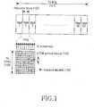
- FIG. 1illustrates a conventional OFDM-based downlink frame structure of Enhanced Universal Terrestrial Radio Access (EUTRA) which is the next generation mobile communication standard of the 3 rd Generation Partnership Project (3GPP).
- EUTRAEnhanced Universal Terrestrial Radio Access
- 3GPP3 rd Generation Partnership Project
- RBsResource Blocks
- One RBis composed of 12 subcarriers 103, and can have 14 OFDM symbol intervals 104.
- a modulation symbol of a downlink channelis transmitted on each subcarrier 103.
- one subcarrier band in one OFDM symbol intervalis referred to as a Resource Element (RE) 106, and in FIG.
- REResource Element
- one downlink data channelcan be allocated to one or more RBs according to a data rate, and can be transmitted through the allocated RBs.
- a maximum of 50 downlink data channelscan be simultaneously scheduled in one TTI 105.
- the uplinkneeds 50 ACKCHs.
- a group of multiple REs 106constitutes one ACKCH, and the overhead and performance occupied by the ACKCH in all resources of the system depends on how resources of the ACKCH are formed.
- WO 2004/098098 A1describes a method, apparatus, and system for user-multiplexing in multiple access systems with retransmission, and in particular a method in which a group of users in a system that employs a retransmission mechanism, such as automatic repeat request, is divided into multiple subgroups of users. Each user is assigned a number of channels for the transmission of information. Transmission intervals are automated among the multiple sub-groups such that only one of the sub-groups of the users is allowed to transmit information during any transmission interval. An idle interval during which a particular user in the first group does not transmit information is used as a waiting period for acknowledgment of a previous transmission by the particular user.
- EP 1 657 872 A2describes an apparatus and a method for transmitting a preamble and searching a cell in an OFDMA system, and in particular describes an apparatus and method that consider a cyclic shift in an orthogonal frequency division multiple access system and employ a relatively small number of pseudo-random noise codes for distinguishing base stations.
- a methodis provided for transmitting a preamble in an orthogonal frequency division multiple access system using N subcarriers, comprising generating an allocated pseudo-random noise code of P CODE PN codes from each cell such that all N CODE cells are identified.
- WO 02/03566 A2describes a power control algorithm for packet data based on a queue/channel utilization and in particular describes a method and system for improving the channel quality in a packet data radio network.
- the packet datais measured based on channel utilization and/or packet queue measurements.
- a power control algorithmuses the packet data load to determine a common or equal broadcast or transmitted power level for the channels in the cell. The equal or common power level may also be applied to groups of channels or groups of users.
- OFDMOrthogonal Frequency Division Multiplexing
- 3GPP3 rd Generation Partnership Project
- EUTRAEnhanced Universal Terrestrial Radio Access
- FIGS. 2A and 2Bare diagrams illustrating an example where ACKCH resources have an implicit mapping relation with a data channel(s) or scheduling control channel(s).
- ACKCH resource #1 201has an implicit mapping relation with RB#1 202 used for transmission of a data channel or when ACKCH resource #1 203 has an implicit mapping relation with downlink Control Channel Element (CCE) 204 where data transmitted over the data channel is scheduled
- CCEdownlink Control Channel Element
- Implicit mappingrefers to pre-defined mapping, and indicates that a UE, when transmitting or receiving an ACK/NACK channel, can determine which resource the UE should use, through use of pre-defined mapping between ACK/NACK channel resource and data channel RB or pre-defined mapping between ACK/NACK channel resource and scheduling control channel, without the need to explicitly receive signaling information from a base station.
- the present inventionmaps an ACKCH to a physical resource to improve frequency diversity gain and inter-cell interference diversity gain.
- the present inventionuses the same Resource Block(s) (RB(s)) during Multi-User Multi-Input Multi-Output (MU-MIMO) transmission so ACKCHs from MU-MIMO User Equipments (UEs) receiving transmission data can be transmitted to a base station without mutual interference.
- RB(s)Resource Block(s)
- UEsUser Equipments
- the present inventionbrings performance improvement of ACKCH and efficient utilization of resources when a technology is applied in which multiple ACKCHs are transmitted after being mapped to the same frequency resource using Code Division Multiplexing (CDM).
- CDMCode Division Multiplexing
- An ACKCH resource allocation method and apparatus for a wireless communication systemimplicitly signals physical resources to be used for the ACKCH through use of a mapping relation preset between resources allocated to the data channel and resources allocated to the ACKCH, or between a downlink control channel where the data channel is scheduled and resources allocated to the ACKCH.
- the base stationcan explicitly provide corresponding information to a UE, or can allow the set of REs to be used for ACKCH transmission to have an implicit mapping relation with an RB used for transmission of a downlink data channel or with downlink CCE where data resources are scheduled, as shown in FIGS. 2A and 2B .
- REsResource Elements
- the present inventionmaps physical resources to an ACKCH, when an implicit mapping rule is applied between an ACKCH and an RB of a data channel, or between an ACKCH and a downlink CCE.
- the core of the physical resource mapping methodis to map ACKCHs being mapped to consecutive RBs or CCEs with consecutive indexes, to different frequency resources.
- the mapping processallows REs used for transmission of the ACKCHs to uniformly spread over the entire system band, so the ACKCH resource allocation method and apparatus according to the present invention can uniformly use frequency resources of ACKCHs and achieve good frequency diversity and inter-cell interference diversity in the system where consecutive RBs are allocated for one data channel, like a Single-Carrier Frequency Division Multiple Access (SC-FDMA) system.
- SC-FDMASingle-Carrier Frequency Division Multiple Access
- each ACKCH resource 201 in FIG. 2Ais one physical channel composed of several REs 106 in FIG. 1 , and when transmission of several ACKCHs is permitted through the same REs 106, they are different ACKCH resources 201 since they are different in CDM sequence used for distinguishing each ACKCH. If a UE transmits a data channel using RB#1 202, an ACKCH for the UE is transmitted from the base station using ACKCH resource #1 201 and the UE receives the corresponding ACKCH.
- ACKCH resourcesare implicitly mapped to CCE 204 of a downlink control channel for transmitting scheduling information of the data channel.
- CCE 204indicates a set of REs 106 constituting the downlink control channel.
- a UEwhich is scheduled (allocated) an uplink data channel from a control channel based on CCE#1 204, transmits an ACK/NACK signal using ACKCH resource #1 203 mapped to the CCE#1 204.
- the downlink control channelcan be composed of one or multiple CCEs according to the channel state of the UE receiving the control channel, and the amount of information transmitted over the control channel.
- FIG. 3is a diagram illustrating an ACKCH resource allocation method according to a first embodiment of the present invention.
- RBs 302are allocated during data channel transmission in the uplink
- REs 301are used for ACKCH transmission for the uplink data channel in the downlink
- the remaining downlink REsare not shown for convenience.
- FIGS. 5A and 5Bare diagrams illustrating the situation in which downlink channels are mapped to REs separately for each cell.
- REs denoted by reference numeral 306 and 309 in FIG. 3correspond to REs denoted by reference numeral 501 in FIGS. 5A and 5B ;
- REs denoted by reference numeral 307 and 310 in FIG. 3correspond to REs denoted by reference numeral 502 in FIGS. 5A and 5B ;
- REs denoted by reference numeral 308 and 311 in FIG. 3correspond to REs denoted by reference numeral 503 in FIGS. 5A and 5B .
- a base stationsince downlink ACKCH for uplink data channel transmitted using RB#1 is mapped to REs 306 and 309 (see 303), a base station transmits an ACK/NACK signal using the REs 306 and 309 after receiving the data channel from a UE, and the UE receives ACK/NACK signal from the REs through use of a particular mapping rule 303.
- downlink ACKCH for the uplink data channel transmitted using RB#2is transmitted using REs 307 and 310.
- the REs 306 and 309, and the REs 307 and 310preferably have bands spaced apart to some extent in order to obtain frequency diversity gain.
- the present inventionis more advantageous to a case where more than two consecutive RBs are allocated for data channel transmission.
- consecutive RBsare usually allocated in order to satisfy the single-carrier transmission characteristic when more than two RBs are allocated for data channel transmission.
- a base stationcan use REs 307, 308, 310 and 311 for ACKCH transmission by means of mapping rules 304 and 305.
- an ACK/NACK signalis distributed over four RE groups 307, 308, 310 and 311 during transmission of the ACK/NACK signal, making it possible to improve frequency diversity and inter-cell interference diversity gains as several ACKCH frequency resources are uniformly used as compared with the case where only the RE groups 307 and 310, or 308 and 311 mapped to one RB are used.
- one RE groupis composed of four adjacent REs, and the present invention is not limited to an RE group having a specific size and can be applied regardless of the number of REs belonging to the RE group.
- ACKCHwhen a data channel is transmitted using three arbitrary consecutive RBs, ACKCH can be transmitted using all of six RE groups 306 ⁇ 311. For example, when RB#3, RB#4 and RB#5 are used for data channel transmission, all of ACKCH resources 315, 316 and 317 mapped to the three RBs are used, so the ACKCH is distributed over six RE groups 306-311 during transmission of the ACKCH. In this case, in each RE group, sequences allocated to the ACKCH resources 315, 316 and 317 are used.
- ACKCH resources 313, 316, 319 and 320exist in the RE group 309 in order to transmit ACKCH mapped to RB#1, RB#4, RB#7 and RB#10, and the four ACKCH resources 313, 316, 319 and 320 are transmitted over the same frequency resources.
- the four ACKCH resources 313, 316, 319 and 320, as shown in FIG. 4are allocated sequences having mutual orthogonality or quasi-orthogonality separately for each ACKCH resource so they can be distinguished in the code domain.
- FIG. 4is a diagram illustrating a process of mapping multiple ACKCHs to the same RE group according to the first embodiment of the present invention.
- an ACK/NACK signal to be transmittedis defined as 'b' when a ACKCH mapped to a data channel transmitted on RB#1 is transmitted
- s11xb, s12xb, sl3xb and s14xbare formed in the RE group 309 by multiplying the ACK/NACK signal b by sequences 402 of s11, s12, s13 and s14, respectively, and transmitted over RE#1, RE#2, RE#3 and RE#4, respectively.
- sequences 402 of s11, s12, s13 and s14can be made by multiplying orthogonal sequences such as length-4 Walsh or DFT sequences by cell-specific random sequences. Since sequences having a long length are generally applied for the cell-specific random sequences, every RE group has a different sequence value.
- ACKCH corresponding to a data channel transmitted on RB#7an ACK/NACK signal to be transmitted on the RE group 309 are multiplied by sequences 404 of s31, s32, s33 and s34, and transmitted on RE#1, RE#2, RE#3 and RE#4, respectively. Therefore, according to this first embodiment, ACKCHs being mapped to RBs RB#1, RB#4, RB#7 and RB#10 spaced apart from each other can be transmitted by applying different sequences to the same frequency resource, i.e., by applying CDM. This is because ACKCHs belonging to consecutive RBs are mapped to different frequency resources in FIG. 3 .
- length-4 sequencesare applied separately for each RE group.
- length-8 sequencescan be applied. In this case, 8 different ACKCHs can be transmitted on one RE group.
- FIG. 5Ashowing an example where ACKCH resources are allocated to several cells is an example where RE groups 306 ⁇ 311 allocated to ACKCH of FIG. 3 , referred to herein as ACKCH RE groups, are mapped to physical resources at regular frequency intervals. That is, RE groups 501, 502 and 503 correspond to RE groups 306, 307 and 308 of FIG. 3 , respectively.
- the RE groups 501 ⁇ 503are spaced apart from each other at intervals of two RBs.
- FIGS. 5A and 5BCell#11, Cell#12 and Cell#13 are cells belonging to the same base station, and similarly, Cell#21 and Cell#23 are also cells belonging to the same base station.
- FIGS. 5A and 5Bshow REs 504 and 505 mapped to a Reference Signal (RS) for channel estimation and REs 506 mapped to control channels and data.
- RSReference Signal
- ACKCH corresponding to a data channel transmitted using three or more arbitrary consecutive RBscan always be transmitted using all of RE groups 501, 502, 503, making it possible to improve frequency diversity gain and inter-cell interference diversity gain as compared with the case where only one of the RE groups 501 ⁇ 503 is used.
- two consecutive RBsare allocated for data channel transmission, two RE groups among the RE groups 501 ⁇ 503 are always selected for transmission of ACKCH, making it possible to obtain improved performance.
- each ACKCH RE group shown in FIG. 5Ahas a cell-specific offset to reduce interference between ACKCHs of different cells. For example, since Cell#11, Cell#12 and Cell#13 belong to the same base station, ACKCHs from the cells are transmitted on different REs, preventing occurrence of mutual interference. However, since there is a limitation on the applicable offset value, there is a possible case where some ACKCHs from different cells use the same REs as done in Cell#21 and Cell#31.
- FIG. 5BShown in FIG. 5B is an example where the ACKCH RE groups 306 ⁇ 311 have the cell-specific random frequency interval. Therefore, while RE groups corresponding to ACKCHs show a distance difference corresponding to the same frequency offset between two arbitrary cells in FIG. 5A , an interval between ACKCH RE groups is random in FIG. 5B , making it possible to more randomize interference from ACKCHs of different cells. Even in FIG. 5B
- ACKCH RE mapping with RB in each cellwhen more than two consecutive RBs are used for data channel transmission as described above, at least two RE groups among the RE groups 501 ⁇ 503 are used for ACKCH transmission, contributing to improvement of frequency diversity, and since random inter-cell ACKCH RE mapping is applied, an inter-cell ACKCH interference randomization effect can further increase.
- FIG. 6is a control flow diagram illustrating an ACKCH transmission procedure of a transmission apparatus of a base station according to the first embodiment of the present invention.
- the transmission apparatus of the base stationdetermines an ACK/NACK value according to the decoding result on a data channel received from a UE, and prepares to transmit an ACKCH signal.
- the transmission apparatus of the base stationchecks the number of RBs allocated to the received data channel, and when only one RB is allocated for the data channel, the transmission apparatus of the base station maps an ACK/NACK signal to an ACKCH RE group mapped to the RB in step 602.
- step 603the transmission apparatus of the base station multiplies the ACK/NACK signal by a CDM sequence for each of the ACKCH resources separately for each RE.
- a CDM sequencefor each of the ACKCH resources separately for each RE.
- the transmission apparatus of the base stationdetermines in step 610 whether the number of RBs allocated for transmission of the data channel is greater than three, and when two or three RBs are allocated to the data channel, the transmission apparatus of the base station maps a transmission ACK/NACK signal to an ACKCH RE group mapped to the RBs in step 604. Referring to FIG. 3 , when RB#2 and RB#3 are allocated to the data channel, the transmission apparatus of the base station maps the ACK/NACK signal to RE groups 307, 308, 310 and 311 mapped thereto.
- the number of RBswhich is a criterion for determination in step 610
- the number of RBswhich is a criterion for determination in step 610
- the number of RBscan be set to two rather than three regardless of the number of sets.
- the transmission apparatus of the base stationonly needs to always use only two ACKCH resources regardless of the number of allocated RBs.
- the transmission apparatus of the base stationmultiplies each of RE groups, to which the ACK/NACK signal is mapped in step 604, by a corresponding CDM sequence.
- the transmission apparatus of the base stationselects ACKCH resources mapped to RBs corresponding to the first three indexes among the RBs in step 606. Referring to FIG. 3 , when RB#2 ⁇ RB#7 are allocated to the data channel, ACKCH resources 314, 315 and 316 corresponding to RB#2, RB#3 and RB#4 are selected.
- the transmission apparatus of the base stationmaps the ACK/NACK signal to the ACKCH resources selected in step 606.
- the transmission apparatus of the base stationmultiplies the ACK/NACK signal by CDM sequences corresponding to the ACKCH resources separately for each RE group.
- the transmission apparatus of the base stationadjusts a transmission level of a signal on ACKCH RE according to the number of RE groups used for ACKCH channel transmission for the data channel. For example, when the number of RBs allocated to the data channel is three, the level is adjusted to 1/3, compared to when the number of RBs is one. This is to keep the total power of the transmission ACKCH signal constant regardless of the number of RE groups used for the ACKCH transmission.
- the ACKCH signalis mapped to a corresponding Inverse Fast Fourier Transformer (IFFT) input of the transmitter separately for each RE allocated for the ACKCH, and then transmitted. The same transmission procedure can be applied even when the number of RBs allocated to the data channel, which is a criterion for determination in step 610, is set to two and ACKCH resources corresponding to the first two RBs are selected in step 606.
- IFFTInverse Fast Fourier Transformer
- FIG. 7is a control flow diagram illustrating an ACKCH reception procedure of a reception apparatus of a UE according to the first embodiment of the present invention.
- the UEprepares to receive ACKCH from a base station after transmitting a previously scheduled data channel. Thereafter, the UE determines the number of RBs scheduled for the data channel in step 701, and if only one RB is allocated, the UE receives the ACKCH signal from the Fast Fourier Transformer (FFT) outputs of the receiver corresponding to ACKCH REs mapped to the RB in step 702.
- FFTFast Fourier Transformer
- the UEdespreads the ACKCH signal received in step 702 using sequences corresponding to the ACKCH resources.
- step 701determines in step 701 that the number of RBs scheduled for the data channel is greater than one
- the UEproceeds to step 710 where the UE determines whether the number of RBs allocated to the data channel is greater than three. If the number of allocated RBs is two or three, the UE proceeds to step 704 where the UE receives the ACKCH signal from FFT outputs corresponding to the ACKCH REs mapped to the RBs. Thereafter, in step 705, the UE despreads the ACKCH signal received in step 704 using sequences corresponding to the ACKCH resources.
- step 710determines in step 710 that the number of RBs allocated to the data channel is greater than three
- the UEproceeds to step 706 where the UE selects ACKCH resources mapped to the first three RB indexes among the RBs. Thereafter, the UE receives an ACKCH signal from FFT outputs corresponding to the selected resources in step 707, and then despreads the received ACKCH signal using sequences corresponding to the ACKCH resources in step 708. Thereafter, in step 709, the UE determines whether an ACK/NACK signal is received from the despread ACKCH signal.
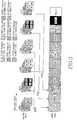
- FIG. 8is a diagram illustrating a structure of the transmission apparatus of the base station of FIG. 6 according to the first embodiment of the present invention.
- An ACK/NACK symbol generator 801generates an ACK/NACK symbol for a data channel according to the decoding success/failure result of a data channel decoder 805.
- a spreader 802multiplies the generated ACK/NACK symbol by a CDM sequence corresponding to ACKCH resource allocated for transmission of the ACK/NACK symbol to thereby spread the ACK/NACK symbol. Also, the spreader 802 performs scaling on a level of a transmission ACK/NACK signal as done in step 609 of FIG. 6 .
- An ACKCH format controller 806determines an ACKCH format, i.e., spreading gain and ACKCH resources for transmission of ACKCH, according to the number of RBs allocated to the data channel and their indexes, and controls the spreader 802 and a subcarrier mapper 803 depending on the determined ACKCH format.
- the subcarrier mapper 803, under the control of the ACKCH format controller 806,applies the ACKCH symbols spread by the spreader 802 to inputs of an IFFT 804, which are associated with REs of the ACKCH resources.
- An output signal of the IFFT 804is finally transmitted to a UE via an Intermediate Frequency (IF)/Radio Frequency (RF) stage.
- IFIntermediate Frequency
- RFRadio Frequency
- FIG. 9is a diagram illustrating a structure of a reception apparatus of a UE of FIG. 7 according to the first embodiment of the present invention.
- a signal received at the UE from a base stationis first converted into a frequency-domain signal by an FFT 901, and then applied to an input of a subcarrier demapper 902.
- the subcarrier demapper 902receives an output of the FFT 901, and outputs spread ACKCH symbols corresponding to ACKCH resources to be received. Since an ACKCH demapping controller 905 can implicitly determine the ACKCH resources according to the number of RBs used for the previously transmitted data channel and their indexes, the ACKCH demapping controller 905 controls the subcarrier demapper 902 and a despreader 903 according thereto.
- the despreader 903despreads ACKCH symbols extracted by the subcarrier demapper 902 and applies the despread ACKCH symbols to an ACK/NACK symbol detector 904.
- the ACK/NACK symbol detector 904determines whether to transmit an ACK/NACK signal depending on the ACKCH signal despread by the despreader 903.
- ACKCH resourcesare mapped to CCEs as shown in FIG. 2B . That is, resources to be used for ACKCH transmission are determined according to indexes of CCEs used for transmission of a downlink control channel where a data channel is scheduled for the UE.
- mapping structure of FIG. 3 and the transmission/reception procedures of FIGS. 6 and 7when the CCEs allocated to the control channel are applied in place of the RBs allocated to the data channel, the details described in this first embodiment can be applied in the same way.
- the present inventioncan be applied in units of physical resources allocated to data channels.
- a second embodiment of the present inventionapplies the ACKCH resource allocation method shown in FIG. 3 to uplink MU-MIMO.
- MU-MIMOrefers to the case where more than two different users are simultaneously allocated the same RBs for data channel transmission.
- a base stationorders two users having a low spatial channel correlation to transmit the same RBs over data channels, and the reception apparatus of the base station successfully decodes the data channels received from the two users, thereby improving utilization efficiency of uplink physical resources.
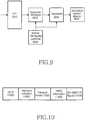
- FIG. 10is a diagram illustrating a format example of a scheduling channel for uplink MU-MIMO transmission according to the second embodiment of the present invention.
- a base stationtransmits the scheduling channel having the format of FIG. 10 to a UE.
- UE ID field 1000indicates ID information of a UE undergoing channel scheduling.
- Resource allocation information for transmission of a data channelis carried on a resource indication field 1001
- Transport Format (TF) informationsuch as Modulation and Coding Set (MCS) level and payload size
- MCSModulation and Coding Set
- HARQ-related informationsuch as HARQ redundancy version and process number is carried on an HARQ information field 1003.
- a value of 0 or 1is set in a MU-MIMO UE flag bit field 1004 for a UE receiving the scheduling channel. That is, the scheduling information is transmitted to two UEs performing MU-MIMO transmission on the same RBs, and the field 1004 is differently set to 0 and 1 separately for the two UEs.
- a UE for which the MU-MIMO UE flag bit field 1004 is set to 0 and a UE for which the MU-MIMO UE flag bit field 1004 is set to 1data channels undergo MU-MIMO transmission through the same RBs but pilot signals for channel estimation for the data channels are mapped to orthogonality-satisfied physical resources before transmission so the base station can receive the pilot signals from the two UEs without mutual interference. Further, for the data packets received from the two UEs, ACKCHs transmitted in the downlink are also set such that they can be transmitted to the two UEs without mutual interference.
- the embodimentconsiders the case where two UEs simultaneously make MU-MIMO transmission on the same RBs, the same can be applied even to the case where N arbitrary UEs simultaneously make MU-MIMO transmission.
- the MU-MIMO UE flagis composed of 2 bits so as to separately designate four users.
- the MU-MIMO UE flagis set to have log 2 (N) bits.
- log 2 (N)is not an integer
- the MU-MIMO UE flagpreferably has bits, the number of which is the minimum integer greater than log 2 (N).
- MU-MIMO transmissionIn order to allow ACKCHs transmitted to the two UEs to be transmitted without mutual interference, for MU-MIMO transmission, more than two RBs are assumed to be allocated herein, and two UEs are assumed herein to simultaneously transmit data channels on the more than two same RBs. Similarly, when N UEs make MU-MIMO transmission, more than N RBs are assumed herein to be allocated.
- FIG. 11illustrates an ACKCH transmission procedure of a base station according to the second embodiment of the present invention.
- a transmission apparatus of the base stationdetermines whether to and prepares to transmit an ACK/NACK signal depending on the decoding result on a data channel for a corresponding UE.
- step 1101the base station determines whether a MU-MIMO UE flag bit field 1004 of the scheduling channel received from the UE is set to 0 or 1. If the base station determines in step 1101 that the MU-MIMO UE flag bit field 1004 is set to 0, the base station proceeds to step 1102 where the base station maps a transmission ACK/NACK signal to ACKCH resource mapped to the smallest even index among the RBs allocated to the UE. However, if the flag bit is set to 1, the base station proceeds to step 1104 where the base station maps the transmission ACK/NACK signal to ACKCH resource mapped to the smallest odd index among the RBs allocated to the UE.
- step 1103the base station multiplies the ACK/NACK signal mapped to the ACKCH resource by a sequence to be applied to the ACKCH resource.
- step 1104the base station finally maps the ACK/NACK signal multiplied by the sequence to IFFT inputs of the transmitter corresponding to the mapped ACKCH resource before transmission.
- the embodimentcan alternatively be applied to the opposite case.
- the ACKCH resources mapped to consecutive RBsare set to use different frequency resources as shown in FIG. 3 , and ACKCHs allocated to two MU-MIMO UEs are transmitted using the different frequency resources according to the value of the MU-MIMO UE flag bit field 1004 as described in the procedure of FIG. 11 , making it possible to always prevent interference from occurring regardless of the power difference between ACKCHs transmitted to the two UEs.
- FIG. 12is a diagram illustrating an ACKCH reception procedure of a UE according to the second embodiment of the present invention.
- a UEprepares to receive ACKCH from a base station after transmitting a previously scheduled data channel.
- the UEdetermines from which ACKCH resource the UE will receive the ACKCH according to the value of a MU-MIMO UE flag bit field 1004 of a scheduling channel for the data channel.
- the UEreceives in step 1202 an ACKCH signal from FFT outputs of the receiver corresponding to ACKCH resource mapped to the smallest even index among the RBs allocated to the UE.
- the UEreceives in step 1204 an ACKCH signal from FFT outputs of the receiver corresponding to ACKCH resource mapped to the smallest odd index among the RBs allocated to the UE. Thereafter, the UE despreads the received ACKCH signal using a sequence applied to the ACKCH resource in step 1203, and finally determines in step 1205 whether an ACK/NACK signal is received.
- the ACKCH resource corresponding to the smallest even or odd indexis selected according to the value of the MU-MIMO UE flag bit field 1004 in the foregoing transmission/reception procedure, other rules can alternatively be established so frequency resources are used as ACKCH resources transmitted to the two MU-MIMO transmission UEs, and the present invention has no limitation thereon.
- the base stationcan set the MU-MIMO UE flag bit 1004 to an appropriate value according to the need, thereby controlling ACK/NACK resource allocation. For example, when the UE is allocated several RBs, ACK/NACK channels can be allowed to be transmitted on frequency resources where a less number of ACK/NACK channels are allocated, using the MU-MIMO UE flag bit 1004.
- a MU-MIMO UE flag bit fieldis defined in a scheduling channel for a downlink data channel as shown by reference numeral 1004 of FIG. 10 , and the base station sets a different value for the MU-MIMO UE flag bit field in each scheduling channel being transmitted to two UEs allocated to the same RBs.
- the UEtransmits an ACK/NACK channel on resources corresponding to the MU-MIMO UE flag bit value among the ACK/NACK channel resources mapped to the RBs.
- the present inventionmaps ACKCHs mapped to consecutive RBs or consecutive CCEs, to different frequency resources, so REs used for transmission of the ACKCHs are uniformly distributed over the entire system band, making it possible to achieve high frequency diversity gain and inter-cell interference diversity gain and improve ACKCH performance even in MU-MIMO.
- the present inventioncontributes to a decrease in the number of unnecessary data retransmissions by improving ACKCH performance, and an increase in the system capacity by improving retransmission probability for the data channel failed in its normal reception.
Landscapes
- Engineering & Computer Science (AREA)
- Signal Processing (AREA)
- Computer Networks & Wireless Communication (AREA)
- Mobile Radio Communication Systems (AREA)
Description
- The present invention generally relates to a resource allocation method and apparatus for a wireless communication system, and in particular, to a method and apparatus for allocating positive Acknowledgement (ACK)/Negative Acknowledgement (NACK) physical channel, referred to herein as ACKCH, resources with which a reception side notifies a transmission side of the success/failure in decoding of a received data channel.
- In wireless communication systems, the technology for controlling a transmission error during data transmission is generally classified into a Forward Error Correction (FEC) technique and an Automatic Repeat reQuest (ARQ) technique. The FEC technique attempts to correct an error detected from received data, and decodes correct data upon success in the error correction. However, when the FEC technique has failed in the error correction, wrong information may be provided to users or the information may be missing. The ARQ technique transmits data using an FEC code having a high error detection capability, and when an error is detected from received data, a reception side sends a request for data retransmission to a transmission side.
- The FEC technique has a relatively lower efficiency in a good channel environment, and reduces system reliability when the FEC technique fails in the error correction. On the contrary, the ARQ technique typically secures high system reliability and enables efficient transmission with a low redundancy, but the system reliability is considerably reduced in a poor channel environment due to the frequent retransmission request. In order to address such shortcomings, the two techniques have been appropriately combined to provide a Hybrid ARQ (HARQ) technique.
- The HARQ technique basically attempts error correction on received coded data, referred to herein as a HARQ packet, and determines whether to make a retransmission request for the HARQ packet using a simple error detection code, such as a Cyclic Redundancy Check (CRC) code. A reception side of a system using the HARQ technique determines presence/absence of an error in a received HARQ packet, and transmits an HARQ Positive Acknowledgement (ACK) signal or an HARQ Negative Acknowledgement (NACK) signal to a transmission side according to the presence/absence of an error. The transmission side performs retransmission of the HARQ packet or transmission of a new HARQ packet according to the HARQ ACK/NACK signal. Upon normal receipt of an HARQ packet, the reception side transmits the ACK/NACK signal using appropriate resources. Particularly, when the HARQ technique is used, a channel over which the ACK/NACK signal is transmitted is call a Physical Hybrid ARQ Indicator Channel (PHICH).
- An Orthogonal Frequency Division Multiplexing (OFDM)-based wireless communication system transmits the ACK/NACK signal on several subcarriers, and a Wideband Code Division Multiple Access (WCDMA) system transmits the ACK/NACK signal on a particular code channel. Generally, since packet data for several users is simultaneously transmitted in an arbitrary packet data transmission interval or Transmission Time Interval (TTI), ACKCHs for each of the HARQ packets are transmitted at particular times after the data received from the users which are scheduled data in the TTI is decoded.
- Transmission of the ACKCH will be considered below separately for the downlink and the uplink. Regarding ACKCH for downlink data channels, each terminal or User Equipment (UE) that has received each of the data channels from a base station is allocated physical channel resources for transmitting the ACK/NACK signal from the base station, and transmits the ACKCH on the uplink. Meanwhile, regarding ACKCH for uplink data channels, after a base station receives the data channels from corresponding UEs, the base station transmits ACKCH for each data packet over the resources agreed upon between the base station and each UE.
FIG. 1 illustrates a conventional OFDM-based downlink frame structure of Enhanced Universal Terrestrial Radio Access (EUTRA) which is the next generation mobile communication standard of the 3rd Generation Partnership Project (3GPP). Referring toFIG. 1 , a total of 50 Resource Blocks (RBs) 102 exist in a 10-MHz system bandwidth 101. One RB is composed of 12subcarriers 103, and can have 14OFDM symbol intervals 104. In everyOFDM symbol interval 104, a modulation symbol of a downlink channel is transmitted on eachsubcarrier 103. As shown above, one subcarrier band in one OFDM symbol interval is referred to as a Resource Element (RE) 106, and inFIG. 1 , a total of 168 (=14 OFDM symbols × 12 subcarriers) REs exist in one RB. In oneOFDM symbol interval 104, one downlink data channel can be allocated to one or more RBs according to a data rate, and can be transmitted through the allocated RBs.- With consideration of the downlink frame structure of
FIG. 1 , a maximum of 50 downlink data channels can be simultaneously scheduled in oneTTI 105. In this case, the uplink needs 50 ACKCHs. Generally, a group ofmultiple REs 106 constitutes one ACKCH, and the overhead and performance occupied by the ACKCH in all resources of the system depends on how resources of the ACKCH are formed. - Therefore, in order to improve the overhead and performance occupied by ACKCH in all resources of the system, a need exists for a scheme for efficiently allocating and forming resources of the ACKCH.
WO 2004/098098 A1 , describes a method, apparatus, and system for user-multiplexing in multiple access systems with retransmission, and in particular a method in which a group of users in a system that employs a retransmission mechanism, such as automatic repeat request, is divided into multiple subgroups of users. Each user is assigned a number of channels for the transmission of information. Transmission intervals are automated among the multiple sub-groups such that only one of the sub-groups of the users is allowed to transmit information during any transmission interval. An idle interval during which a particular user in the first group does not transmit information is used as a waiting period for acknowledgment of a previous transmission by the particular user.EP 1 657 872 A2WO 02/03566 A2 - The 3GPP contribution document "Downlink Acknowledgement and Group Transmit Indicator", Motorola, March 26-30, 2007, 3GPP TSG RAN1 #48bis, describes downlink acknowledgement using hybrid CDM/FDM for multiplexing acknowledgements and an implicit relation for ACK/NACK resource assignment based on uplink resources.
- The 3GPP contribution document "ACK/NAK Channel Transmission in E-UTRA Downlink", Texas Instruments, January 15-19, 2007, 3GPP TSG RAN1 #47bis, describes hybrid FDM/CDM techniques for frequency diversity of downlink ACK/NACK transmission.
- It is the object of the invention to provide a method and an apparatus for allocating ACKCH resources in a wireless communication system.
- The invention is defined by the independent claims.
- Preferred embodiments are defined in dependent claims.
- The above and other aspects, features and advantages of the present invention will become more apparent from the following detailed description when taken in conjunction with the accompanying drawings in which:
FIG. 1 is a diagram illustrating a conventional OFDM-based downlink frame structure;FIGS. 2A and 2B are diagrams illustrating an example where ACKCH resources have an implicit mapping relation with a data channel or a scheduling control channel according to the present invention;FIG. 3 is a diagram illustrating an ACKCH resource allocation method according to a first embodiment of the present invention;FIG. 4 is a diagram illustrating a process of mapping multiple ACKCHs to the same RE group according to the first embodiment of the present invention;FIGS. 5A and 5B are diagrams illustrating a situation in which downlink channels are mapped to REs separately for each cell according to the first embodiment of the present invention;FIG. 6 is a control flow diagram illustrating an ACKCH transmission procedure of a transmission apparatus of a base station according to the first embodiment of the present invention;FIG. 7 is a control flow diagram illustrating an ACKCH reception procedure of a reception apparatus of a UE according to the first embodiment of the present invention;FIG. 8 is a diagram illustrating a structure of the transmission apparatus of the base station ofFIG. 6 according to the first embodiment of the present invention;FIG. 9 is a diagram illustrating a structure of a reception apparatus of a UE ofFIG. 7 according to the first embodiment of the present invention;FIG. 10 is a diagram illustrating a format example of a scheduling channel for uplink MU-MIMO transmission according to a second embodiment of the present invention;FIG. 11 is a diagram illustrating an ACKCH transmission procedure of a base station according to the second embodiment of the present invention; andFIG. 12 is a diagram illustrating an ACKCH reception procedure of a UE according to the second embodiment of the present invention.- Preferred embodiments of the present invention will now be described in detail with reference to the annexed drawings. In the following description, a description of known functions and configurations incorporated herein has been omitted for clarity and conciseness. Terms used herein are based on functions in the present invention and may vary according to users, operators' intention or usual practices. Therefore, the definition of the terms should be made based on contents throughout the specification. In particular, Acknowledgement (ACK)/Negative Acknowledgement (NACK) physical channel (ACKCH) and Physical Hybrid ARQ Indicator Channel (PHICH) used throughout this disclosure each indicate a channel over which an ACK/NACK signal is transmitted.
- Although embodiments of the present invention will be described below mainly for an Orthogonal Frequency Division Multiplexing (OFDM)-based wireless communication system, especially for the 3rd Generation Partnership Project (3GPP) Enhanced Universal Terrestrial Radio Access (EUTRA) standard, those skilled in the art should understand that the present invention can be applied to other communication systems having the similar technical background and channel format with a slight modification without departing from the scope of the invention.
- The present invention provides a method and apparatus for allocating resources for ACKCH in a wireless communication system.
FIGS. 2A and 2B are diagrams illustrating an example where ACKCH resources have an implicit mapping relation with a data channel(s) or scheduling control channel(s). According to the present invention, as shown inFIGS. 2A and 2B , whenACKCH resource # 1 201 has an implicit mapping relation withRB# 1 202 used for transmission of a data channel or whenACKCH resource # 1 203 has an implicit mapping relation with downlink Control Channel Element (CCE) 204 where data transmitted over the data channel is scheduled, the ACKCH resources existing in several frequency domains in the system band are uniformly used without being concentrated on a particular frequency domain. Implicit mapping, as used herein, refers to pre-defined mapping, and indicates that a UE, when transmitting or receiving an ACK/NACK channel, can determine which resource the UE should use, through use of pre-defined mapping between ACK/NACK channel resource and data channel RB or pre-defined mapping between ACK/NACK channel resource and scheduling control channel, without the need to explicitly receive signaling information from a base station. - In addition, the present invention maps an ACKCH to a physical resource to improve frequency diversity gain and inter-cell interference diversity gain.
- Further, the present invention uses the same Resource Block(s) (RB(s)) during Multi-User Multi-Input Multi-Output (MU-MIMO) transmission so ACKCHs from MU-MIMO User Equipments (UEs) receiving transmission data can be transmitted to a base station without mutual interference. In particular, the present invention brings performance improvement of ACKCH and efficient utilization of resources when a technology is applied in which multiple ACKCHs are transmitted after being mapped to the same frequency resource using Code Division Multiplexing (CDM).
- An ACKCH resource allocation method and apparatus for a wireless communication system according to the present invention implicitly signals physical resources to be used for the ACKCH through use of a mapping relation preset between resources allocated to the data channel and resources allocated to the ACKCH, or between a downlink control channel where the data channel is scheduled and resources allocated to the ACKCH.
- Regarding physical resources, i.e., a set of Resource Elements (REs), to be used for transmission of each ACKCH, the base station can explicitly provide corresponding information to a UE, or can allow the set of REs to be used for ACKCH transmission to have an implicit mapping relation with an RB used for transmission of a downlink data channel or with downlink CCE where data resources are scheduled, as shown in
FIGS. 2A and 2B . - More specifically, referring to
FIGS. 2A and 2B , the present invention maps physical resources to an ACKCH, when an implicit mapping rule is applied between an ACKCH and an RB of a data channel, or between an ACKCH and a downlink CCE. The core of the physical resource mapping method is to map ACKCHs being mapped to consecutive RBs or CCEs with consecutive indexes, to different frequency resources. The mapping process allows REs used for transmission of the ACKCHs to uniformly spread over the entire system band, so the ACKCH resource allocation method and apparatus according to the present invention can uniformly use frequency resources of ACKCHs and achieve good frequency diversity and inter-cell interference diversity in the system where consecutive RBs are allocated for one data channel, like a Single-Carrier Frequency Division Multiple Access (SC-FDMA) system. - As shown in
FIGS. 2A and 2B , when implicit mapping is used, the base station has no need to explicitly signal ACKCH resources to a UE, contributing to a considerable reduction in or removal of signaling overhead of ACKCH resources. Shown inFIG. 2A is an example where ACKCH resources are mapped to N RBs on a one-to-one basis. EachACKCH resource 201 inFIG. 2A is one physical channel composed ofseveral REs 106 inFIG. 1 , and when transmission of several ACKCHs is permitted through thesame REs 106, they aredifferent ACKCH resources 201 since they are different in CDM sequence used for distinguishing each ACKCH. If a UE transmits a data channel usingRB# 1 202, an ACKCH for the UE is transmitted from the base station usingACKCH resource # 1 201 and the UE receives the corresponding ACKCH. - Meanwhile, shown in
FIG. 2B is an example where ACKCH resources are implicitly mapped toCCE 204 of a downlink control channel for transmitting scheduling information of the data channel. In the above,CCE 204 indicates a set ofREs 106 constituting the downlink control channel. For example, a UE, which is scheduled (allocated) an uplink data channel from a control channel based onCCE# 1 204, transmits an ACK/NACK signal usingACKCH resource # 1 203 mapped to theCCE# 1 204. The downlink control channel can be composed of one or multiple CCEs according to the channel state of the UE receiving the control channel, and the amount of information transmitted over the control channel. - A description will now be made of an ACKCH resource mapping and signaling technology according to the present invention.
FIG. 3 is a diagram illustrating an ACKCH resource allocation method according to a first embodiment of the present invention. In the first embodiment of the present invention,RBs 302 are allocated during data channel transmission in the uplink,REs 301 are used for ACKCH transmission for the uplink data channel in the downlink, and the remaining downlink REs are not shown for convenience.- Meanwhile, shown in
FIGS. 5A and 5B is an example where REs 501, 502 and 503 used for transmission of ACKCH andREs FIGS. 5A and 5B are diagrams illustrating the situation in which downlink channels are mapped to REs separately for each cell. REs denoted byreference numeral FIG. 3 correspond to REs denoted by reference numeral 501 inFIGS. 5A and 5B ; REs denoted byreference numeral FIG. 3 correspond to REs denoted by reference numeral 502 inFIGS. 5A and 5B ; and REs denoted byreference numeral FIG. 3 correspond to REs denoted by reference numeral 503 inFIGS. 5A and 5B . - In
FIG. 3 , since thehorizontal axis 312 represents frequency, the REs spaced farther from each other are significantly different in frequency on the downlink transmission band. As shown inFIG. 3 , REs denoted byreference numeral 306 and REs denoted byreference numeral 311 are located in the opposite sides on the transmission band. Although a description of the first embodiment is given herein as to downlink ACKCH for an uplink data channel, the same can be applied even to uplink ACKCH for a downlink data channel. - According to a mapping rule between
uplink RB 302 anddownlink ACKCH 301 shown inFIG. 3 , since downlink ACKCH for uplink data channel transmitted usingRB# 1 is mapped toREs 306 and 309 (see 303), a base station transmits an ACK/NACK signal using theREs particular mapping rule 303. Similarly, downlink ACKCH for the uplink data channel transmitted usingRB# 2 is transmitted usingREs REs REs - The present invention is more advantageous to a case where more than two consecutive RBs are allocated for data channel transmission. Particularly, in the EUTRA uplink, since the SC-FDMA transmission scheme is used, consecutive RBs are usually allocated in order to satisfy the single-carrier transmission characteristic when more than two RBs are allocated for data channel transmission. For example, in
FIG. 3 , ifRB# 2 andRB# 3 are allocated for transmission of a certain data channel and a UE transmits the data channel using the RBs, a base station can useREs mapping rules REs RE groups RE groups - If several ACKCH frequency resources are uniformly used in this way, performance reduction caused by the mutual interference between ACKCHs multiplexed to the concentrated frequency resources as ACKCH transmission is concentrated only on particular frequency resources can be prevented. Meanwhile, in this first embodiment, one RE group is composed of four adjacent REs, and the present invention is not limited to an RE group having a specific size and can be applied regardless of the number of REs belonging to the RE group.
- According to the mapping method shown in
FIG. 3 , when a data channel is transmitted using three arbitrary consecutive RBs, ACKCH can be transmitted using all of sixRE groups 306∼311. For example, whenRB# 3,RB# 4 andRB# 5 are used for data channel transmission, all ofACKCH resources ACKCH resources - In addition, four
ACKCH resources RE group 309 in order to transmit ACKCH mapped toRB# 1,RB# 4,RB# 7 andRB# 10, and the fourACKCH resources ACKCH resources FIG. 4 , are allocated sequences having mutual orthogonality or quasi-orthogonality separately for each ACKCH resource so they can be distinguished in the code domain. FIG. 4 is a diagram illustrating a process of mapping multiple ACKCHs to the same RE group according to the first embodiment of the present invention. For example, if an ACK/NACK signal to be transmitted is defined as 'b' when a ACKCH mapped to a data channel transmitted onRB# 1 is transmitted, s11xb, s12xb, sl3xb and s14xb are formed in theRE group 309 by multiplying the ACK/NACK signal b by sequences 402 of s11, s12, s13 and s14, respectively, and transmitted overRE# 1,RE# 2,RE# 3 andRE# 4, respectively. In the above process, the sequences 402 of s11, s12, s13 and s14 can be made by multiplying orthogonal sequences such as length-4 Walsh or DFT sequences by cell-specific random sequences. Since sequences having a long length are generally applied for the cell-specific random sequences, every RE group has a different sequence value.- Regarding ACKCH corresponding to a data channel transmitted on
RB# 7, an ACK/NACK signal to be transmitted on theRE group 309 are multiplied bysequences 404 of s31, s32, s33 and s34, and transmitted onRE# 1,RE# 2,RE# 3 andRE# 4, respectively. Therefore, according to this first embodiment, ACKCHs being mapped toRBs RB# 1,RB# 4,RB# 7 andRB# 10 spaced apart from each other can be transmitted by applying different sequences to the same frequency resource, i.e., by applying CDM. This is because ACKCHs belonging to consecutive RBs are mapped to different frequency resources inFIG. 3 . - Although an example where length-4 sequences are applied separately for each RE group is shown in
FIG. 3 andFIG. 4 , if a real part and an imaginary part separately carry one sequence chip during ACK/NACK signal transmission, length-8 sequences can be applied. In this case, 8 different ACKCHs can be transmitted on one RE group. - Meanwhile,
FIG. 5A showing an example where ACKCH resources are allocated to several cells is an example whereRE groups 306∼311 allocated to ACKCH ofFIG. 3 , referred to herein as ACKCH RE groups, are mapped to physical resources at regular frequency intervals. That is, RE groups 501, 502 and 503 correspond toRE groups FIG. 3 , respectively. The RE groups 501∼503 are spaced apart from each other at intervals of two RBs. InFIGS. 5A and 5B ,Cell# 11,Cell# 12 andCell# 13 are cells belonging to the same base station, and similarly, Cell#21 andCell# 23 are also cells belonging to the same base station. However,Cell# 11, Cell#21 andCell# 31 are cells belonging to different base stations. Aside from the RE groups 501∼503 for ACKCH transmission,FIGS. 5A and 5B showREs REs 506 mapped to control channels and data. - According to the ACKCH transmission method shown in
FIG. 3 , ACKCH corresponding to a data channel transmitted using three or more arbitrary consecutive RBs can always be transmitted using all of RE groups 501, 502, 503, making it possible to improve frequency diversity gain and inter-cell interference diversity gain as compared with the case where only one of the RE groups 501∼503 is used. Similarly, when two consecutive RBs are allocated for data channel transmission, two RE groups among the RE groups 501∼503 are always selected for transmission of ACKCH, making it possible to obtain improved performance. - Meanwhile, each ACKCH RE group shown in
FIG. 5A has a cell-specific offset to reduce interference between ACKCHs of different cells. For example, sinceCell# 11,Cell# 12 andCell# 13 belong to the same base station, ACKCHs from the cells are transmitted on different REs, preventing occurrence of mutual interference. However, since there is a limitation on the applicable offset value, there is a possible case where some ACKCHs from different cells use the same REs as done in Cell#21 andCell# 31. - Shown in
FIG. 5B is an example where theACKCH RE groups 306∼311 have the cell-specific random frequency interval. Therefore, while RE groups corresponding to ACKCHs show a distance difference corresponding to the same frequency offset between two arbitrary cells inFIG. 5A , an interval between ACKCH RE groups is random inFIG. 5B , making it possible to more randomize interference from ACKCHs of different cells. Even inFIG. 5B , regarding ACKCH RE mapping with RB in each cell, when more than two consecutive RBs are used for data channel transmission as described above, at least two RE groups among the RE groups 501∼503 are used for ACKCH transmission, contributing to improvement of frequency diversity, and since random inter-cell ACKCH RE mapping is applied, an inter-cell ACKCH interference randomization effect can further increase. FIG. 6 is a control flow diagram illustrating an ACKCH transmission procedure of a transmission apparatus of a base station according to the first embodiment of the present invention. In the transmission procedure ofFIG. 6 , when multiple RBs are allocated to a data channel, the RBs are assumed to be consecutive to each other. Instep 600, the transmission apparatus of the base station determines an ACK/NACK value according to the decoding result on a data channel received from a UE, and prepares to transmit an ACKCH signal. Instep 601, the transmission apparatus of the base station checks the number of RBs allocated to the received data channel, and when only one RB is allocated for the data channel, the transmission apparatus of the base station maps an ACK/NACK signal to an ACKCH RE group mapped to the RB instep 602. Thereafter, instep 603, the transmission apparatus of the base station multiplies the ACK/NACK signal by a CDM sequence for each of the ACKCH resources separately for each RE. Referring toFIG. 4 , whenRB# 1 is allocated to the data channel, a sequence allocated to ACKCH resource of a corresponding RE group is multiplied separately for each RE group as shown by reference numeral 402.- Since three different RE groups 501, 502 and 503 are defined as frequency resources for transmitting ACKCH as shown in
FIGS. 5A and 5B , the transmission apparatus of the base station determines instep 610 whether the number of RBs allocated for transmission of the data channel is greater than three, and when two or three RBs are allocated to the data channel, the transmission apparatus of the base station maps a transmission ACK/NACK signal to an ACKCH RE group mapped to the RBs instep 604. Referring toFIG. 3 , whenRB# 2 andRB# 3 are allocated to the data channel, the transmission apparatus of the base station maps the ACK/NACK signal toRE groups step 610, can be changed according thereto. Meanwhile, the number of RBs, which is a criterion for determination instep 610, can be set to two rather than three regardless of the number of sets. In this case, when multiple RBs are allocated to the data channel, the transmission apparatus of the base station only needs to always use only two ACKCH resources regardless of the number of allocated RBs. Instep 605, the transmission apparatus of the base station multiplies each of RE groups, to which the ACK/NACK signal is mapped instep 604, by a corresponding CDM sequence. - However, if the base station determines in
step 610 that the number of RBs allocated to the data channel exceeds three, the transmission apparatus of the base station selects ACKCH resources mapped to RBs corresponding to the first three indexes among the RBs instep 606. Referring toFIG. 3 , whenRB# 2∼RB# 7 are allocated to the data channel,ACKCH resources RB# 2,RB# 3 andRB# 4 are selected. Instep 607, the transmission apparatus of the base station maps the ACK/NACK signal to the ACKCH resources selected instep 606. Instep 608, the transmission apparatus of the base station multiplies the ACK/NACK signal by CDM sequences corresponding to the ACKCH resources separately for each RE group. - Thereafter, in
step 609, the transmission apparatus of the base station adjusts a transmission level of a signal on ACKCH RE according to the number of RE groups used for ACKCH channel transmission for the data channel. For example, when the number of RBs allocated to the data channel is three, the level is adjusted to 1/3, compared to when the number of RBs is one. This is to keep the total power of the transmission ACKCH signal constant regardless of the number of RE groups used for the ACKCH transmission. Finally, instep 611, the ACKCH signal is mapped to a corresponding Inverse Fast Fourier Transformer (IFFT) input of the transmitter separately for each RE allocated for the ACKCH, and then transmitted. The same transmission procedure can be applied even when the number of RBs allocated to the data channel, which is a criterion for determination instep 610, is set to two and ACKCH resources corresponding to the first two RBs are selected instep 606. FIG. 7 is a control flow diagram illustrating an ACKCH reception procedure of a reception apparatus of a UE according to the first embodiment of the present invention. Instep 700, the UE prepares to receive ACKCH from a base station after transmitting a previously scheduled data channel. Thereafter, the UE determines the number of RBs scheduled for the data channel instep 701, and if only one RB is allocated, the UE receives the ACKCH signal from the Fast Fourier Transformer (FFT) outputs of the receiver corresponding to ACKCH REs mapped to the RB instep 702. Instep 703, the UE despreads the ACKCH signal received instep 702 using sequences corresponding to the ACKCH resources.- However, if the UE determines in
step 701 that the number of RBs scheduled for the data channel is greater than one, the UE proceeds to step 710 where the UE determines whether the number of RBs allocated to the data channel is greater than three. If the number of allocated RBs is two or three, the UE proceeds to step 704 where the UE receives the ACKCH signal from FFT outputs corresponding to the ACKCH REs mapped to the RBs. Thereafter, instep 705, the UE despreads the ACKCH signal received instep 704 using sequences corresponding to the ACKCH resources. - However, if the UE determines in
step 710 that the number of RBs allocated to the data channel is greater than three, the UE proceeds to step 706 where the UE selects ACKCH resources mapped to the first three RB indexes among the RBs. Thereafter, the UE receives an ACKCH signal from FFT outputs corresponding to the selected resources instep 707, and then despreads the received ACKCH signal using sequences corresponding to the ACKCH resources instep 708. Thereafter, instep 709, the UE determines whether an ACK/NACK signal is received from the despread ACKCH signal. FIG. 8 is a diagram illustrating a structure of the transmission apparatus of the base station ofFIG. 6 according to the first embodiment of the present invention. An ACK/NACK symbol generator 801 generates an ACK/NACK symbol for a data channel according to the decoding success/failure result of adata channel decoder 805. Aspreader 802 multiplies the generated ACK/NACK symbol by a CDM sequence corresponding to ACKCH resource allocated for transmission of the ACK/NACK symbol to thereby spread the ACK/NACK symbol. Also, thespreader 802 performs scaling on a level of a transmission ACK/NACK signal as done instep 609 ofFIG. 6 . AnACKCH format controller 806 determines an ACKCH format, i.e., spreading gain and ACKCH resources for transmission of ACKCH, according to the number of RBs allocated to the data channel and their indexes, and controls thespreader 802 and asubcarrier mapper 803 depending on the determined ACKCH format. Thesubcarrier mapper 803, under the control of theACKCH format controller 806, applies the ACKCH symbols spread by thespreader 802 to inputs of anIFFT 804, which are associated with REs of the ACKCH resources. An output signal of theIFFT 804 is finally transmitted to a UE via an Intermediate Frequency (IF)/Radio Frequency (RF) stage.FIG. 9 is a diagram illustrating a structure of a reception apparatus of a UE ofFIG. 7 according to the first embodiment of the present invention. A signal received at the UE from a base station is first converted into a frequency-domain signal by anFFT 901, and then applied to an input of asubcarrier demapper 902. Thesubcarrier demapper 902 receives an output of theFFT 901, and outputs spread ACKCH symbols corresponding to ACKCH resources to be received. Since anACKCH demapping controller 905 can implicitly determine the ACKCH resources according to the number of RBs used for the previously transmitted data channel and their indexes, theACKCH demapping controller 905 controls thesubcarrier demapper 902 and adespreader 903 according thereto. Thedespreader 903 despreads ACKCH symbols extracted by thesubcarrier demapper 902 and applies the despread ACKCH symbols to an ACK/NACK symbol detector 904. The ACK/NACK symbol detector 904 determines whether to transmit an ACK/NACK signal depending on the ACKCH signal despread by thedespreader 903.- The foregoing details described in the first embodiment of the present invention can also be applied to the case where ACKCH resources are mapped to CCEs as shown in
FIG. 2B . That is, resources to be used for ACKCH transmission are determined according to indexes of CCEs used for transmission of a downlink control channel where a data channel is scheduled for the UE. In the mapping structure ofFIG. 3 and the transmission/reception procedures ofFIGS. 6 and7 , when the CCEs allocated to the control channel are applied in place of the RBs allocated to the data channel, the details described in this first embodiment can be applied in the same way. - Although a description of the first embodiment of the present invention has been given for allocation of downlink ACK/NACK physical channel resources for uplink data channels, the same can be applied even for allocation of uplink ACK/NACK physical channel resources for downlink data channels when an OFDM transmission technology is applied in the uplink. In addition, when resources are allocated to the data channel in units of two RBs rather than one RB, one ACKCH resource is mapped to two RBs in
FIGS. 2A and 2B . Accordingly, the present invention can be applied in units of physical resources allocated to data channels. - A second embodiment of the present invention applies the ACKCH resource allocation method shown in
FIG. 3 to uplink MU-MIMO. - MU-MIMO refers to the case where more than two different users are simultaneously allocated the same RBs for data channel transmission. Generally, a base station orders two users having a low spatial channel correlation to transmit the same RBs over data channels, and the reception apparatus of the base station successfully decodes the data channels received from the two users, thereby improving utilization efficiency of uplink physical resources.
FIG. 10 is a diagram illustrating a format example of a scheduling channel for uplink MU-MIMO transmission according to the second embodiment of the present invention. A base station transmits the scheduling channel having the format ofFIG. 10 to a UE.UE ID field 1000 indicates ID information of a UE undergoing channel scheduling. Resource allocation information for transmission of a data channel is carried on aresource indication field 1001, Transport Format (TF) information such as Modulation and Coding Set (MCS) level and payload size is carried on aTransport format field 1002, and HARQ-related information such as HARQ redundancy version and process number is carried on anHARQ information field 1003. A value of 0 or 1 is set in a MU-MIMO UEflag bit field 1004 for a UE receiving the scheduling channel. That is, the scheduling information is transmitted to two UEs performing MU-MIMO transmission on the same RBs, and thefield 1004 is differently set to 0 and 1 separately for the two UEs.- Therefore, regarding a UE for which the MU-MIMO UE
flag bit field 1004 is set to 0 and a UE for which the MU-MIMO UEflag bit field 1004 is set to 1, data channels undergo MU-MIMO transmission through the same RBs but pilot signals for channel estimation for the data channels are mapped to orthogonality-satisfied physical resources before transmission so the base station can receive the pilot signals from the two UEs without mutual interference. Further, for the data packets received from the two UEs, ACKCHs transmitted in the downlink are also set such that they can be transmitted to the two UEs without mutual interference. - Aside from the
fields 1000∼1004, additional information can be transmitted on the scheduling channel, and the present invention has no limitation on transmission of the additional information. Although the embodiment considers the case where two UEs simultaneously make MU-MIMO transmission on the same RBs, the same can be applied even to the case where N arbitrary UEs simultaneously make MU-MIMO transmission. For example, when MU-MIMO transmission is allowed for a maximum of four UEs, the MU-MIMO UE flag is composed of 2 bits so as to separately designate four users. When MU-MIMO transmission is allowed for a maximum of N UEs, the MU-MIMO UE flag is set to have log2(N) bits. When log2(N) is not an integer, the MU-MIMO UE flag preferably has bits, the number of which is the minimum integer greater than log2(N). - In order to allow ACKCHs transmitted to the two UEs to be transmitted without mutual interference, for MU-MIMO transmission, more than two RBs are assumed to be allocated herein, and two UEs are assumed herein to simultaneously transmit data channels on the more than two same RBs. Similarly, when N UEs make MU-MIMO transmission, more than N RBs are assumed herein to be allocated.
FIG. 11 illustrates an ACKCH transmission procedure of a base station according to the second embodiment of the present invention. In the procedure ofFIG. 11 , for MU-MIMO transmission, more than two RBs are assumed to be allocated, and two UEs simultaneously are assumed to transmit data channels on the more than two same RBs. With reference toFIG. 11 , a description will be made of an ACKCH allocation procedure applied separately to each MU-MIMO user. Instep 1100, a transmission apparatus of the base station determines whether to and prepares to transmit an ACK/NACK signal depending on the decoding result on a data channel for a corresponding UE. Instep 1101, the base station determines whether a MU-MIMO UEflag bit field 1004 of the scheduling channel received from the UE is set to 0 or 1. If the base station determines instep 1101 that the MU-MIMO UEflag bit field 1004 is set to 0, the base station proceeds to step 1102 where the base station maps a transmission ACK/NACK signal to ACKCH resource mapped to the smallest even index among the RBs allocated to the UE. However, if the flag bit is set to 1, the base station proceeds to step 1104 where the base station maps the transmission ACK/NACK signal to ACKCH resource mapped to the smallest odd index among the RBs allocated to the UE. Instep 1103, the base station multiplies the ACK/NACK signal mapped to the ACKCH resource by a sequence to be applied to the ACKCH resource. Instep 1104, the base station finally maps the ACK/NACK signal multiplied by the sequence to IFFT inputs of the transmitter corresponding to the mapped ACKCH resource before transmission.- Although the
flag bit 0 is mapped to the ACKCH resource mapped to the smallest even index among RBs and theflag bit 1 is mapped to the ACKCH resource mapped to the smallest odd index among RBs in this embodiment, the embodiment can alternatively be applied to the opposite case. - Therefore, the ACKCH resources mapped to consecutive RBs are set to use different frequency resources as shown in
FIG. 3 , and ACKCHs allocated to two MU-MIMO UEs are transmitted using the different frequency resources according to the value of the MU-MIMO UEflag bit field 1004 as described in the procedure ofFIG. 11 , making it possible to always prevent interference from occurring regardless of the power difference between ACKCHs transmitted to the two UEs. FIG. 12 is a diagram illustrating an ACKCH reception procedure of a UE according to the second embodiment of the present invention. Instep 1200, a UE prepares to receive ACKCH from a base station after transmitting a previously scheduled data channel. Instep 1201, the UE determines from which ACKCH resource the UE will receive the ACKCH according to the value of a MU-MIMO UEflag bit field 1004 of a scheduling channel for the data channel. When the value of the MU-MIMO UEflag bit field 1004 is 0, the UE receives instep 1202 an ACKCH signal from FFT outputs of the receiver corresponding to ACKCH resource mapped to the smallest even index among the RBs allocated to the UE. However, if the value of the MU-MIMO UEflag bit field 1004 is 1, the UE receives instep 1204 an ACKCH signal from FFT outputs of the receiver corresponding to ACKCH resource mapped to the smallest odd index among the RBs allocated to the UE. Thereafter, the UE despreads the received ACKCH signal using a sequence applied to the ACKCH resource instep 1203, and finally determines instep 1205 whether an ACK/NACK signal is received.- Although the ACKCH resource corresponding to the smallest even or odd index is selected according to the value of the MU-MIMO UE
flag bit field 1004 in the foregoing transmission/reception procedure, other rules can alternatively be established so frequency resources are used as ACKCH resources transmitted to the two MU-MIMO transmission UEs, and the present invention has no limitation thereon. - Regarding the MU-MIMO
UE flag bit 1004, when data channels are not scheduled for MU-MIMO transmission, the base station can set the MU-MIMOUE flag bit 1004 to an appropriate value according to the need, thereby controlling ACK/NACK resource allocation. For example, when the UE is allocated several RBs, ACK/NACK channels can be allowed to be transmitted on frequency resources where a less number of ACK/NACK channels are allocated, using the MU-MIMOUE flag bit 1004. - The method described in the second embodiment can be applied even for downlink MU-MIMO in the same way. In this case, a MU-MIMO UE flag bit field is defined in a scheduling channel for a downlink data channel as shown by
reference numeral 1004 ofFIG. 10 , and the base station sets a different value for the MU-MIMO UE flag bit field in each scheduling channel being transmitted to two UEs allocated to the same RBs. Thus, in MU-MIMO, when more than two RBs are allocated to a data channel, the UE transmits an ACK/NACK channel on resources corresponding to the MU-MIMO UE flag bit value among the ACK/NACK channel resources mapped to the RBs. - As is apparent from the foregoing description, the present invention maps ACKCHs mapped to consecutive RBs or consecutive CCEs, to different frequency resources, so REs used for transmission of the ACKCHs are uniformly distributed over the entire system band, making it possible to achieve high frequency diversity gain and inter-cell interference diversity gain and improve ACKCH performance even in MU-MIMO.
- In addition, the present invention contributes to a decrease in the number of unnecessary data retransmissions by improving ACKCH performance, and an increase in the system capacity by improving retransmission probability for the data channel failed in its normal reception.
- While the invention has been shown and described with reference to certain preferred embodiments thereof, it will be understood by those skilled in the art that various changes in form and details may be made therein without departing from the
scope of the invention as defined by the appended claims.
Claims (6)
- A method for allocating physical resources to an Acknowledgement/ Negative Acknowledgement, ACK/NACK, signal channel representative of a response signal in a wireless communication system, the method comprising:decoding a data channel or a control channel received through a plurality of consecutive uplink resource blocks (303-305);generating a downlink ACK/NACK symbol according to success/failure in the decoding;grouping ACK/NACK signal channels into a plurality of groups (306-311) based on uplink resource block indices so that ACK/NACK signal channels of adjacent uplink resource blocks (303-305) do not belong to the same group (306-311), wherein ACK/NACK signal channel is used to transmit a downlink ACK/NACK signal in response to the data channel or the control channel received through the plurality of the consecutive uplink resource blocks;allocating same frequency resources to the ACK/NACK signal channels belonging to the same ACK/NACK signal channel group and allocating orthogonal sequences so the ACK/NACK signal channels in each ACK/NACK signal channel group are distinguished in a code domain; andmultiplying the generated ACK/NACK symbol by the orthogonal sequence allocated to the respective ACK/NACK signal channel to spread the generated ACK/NACK symbol.
- The method of claim 1, wherein a number of ACK/NACK signal channel groups has a maximum value obtained by dividing a number of resource blocks used for transmission of the data channel, by four.
- The method of claim 1, wherein the orthogonal sequences are defined based on a cell-specific random sequence.
- The method of claim 1, wherein power between the ACK/NACK signal channel groups is constant.
- The method of one of claims 1 to 4, wherein the consecutive resource blocks are consecutive frequency resources.
- An apparatus for allocating physical resources to an Acknowledgement/ Negative Acknowledgement, ACK/NACK, signal channel representative of a response signal in a wireless communication system, the apparatus comprising:a channel decoder (805) for decoding a data channel or a control channel received through a plurality of consecutive uplink resource blocks (303-305);an ACK/NACK symbol generator (801) for generating a downlink ACK/NACK symbol according to success/failure in the decoding by the channel decoder;an ACK/NACK signal channel format controller (806) for grouping ACK/NACK signal channels corresponding to the consecutive uplink resource blocks into a plurality of groups (306-311) based on a number of and indexes of the uplink resource blocks so that ACK/NACK signal channels of adjacent uplink resource blocks do not belong to the same group, allocating same frequency resources to ACK/NACK signal channels belonging to the same ACK/NACK signal channel group, allocating orthogonal sequences so ACK/NACK signal channels in each ACK/NACK signal channel group are distinguished in a code domain; anda spreader (802) for multiplying the generated downlink ACK/NACK symbol by the orthogonal sequence allocated to the respective ACK/NACK signal channel for transmitting the generated downlink ACK/NACK symbol, to spread the generated downlink ACK/NACK symbol.
Priority Applications (1)
| Application Number | Priority Date | Filing Date | Title |
|---|---|---|---|
| EP18156296.8AEP3361665B1 (en) | 2007-04-26 | 2008-04-25 | Method and apparatus for allocating ackch resources in a wireless communication system |
Applications Claiming Priority (2)
| Application Number | Priority Date | Filing Date | Title |
|---|---|---|---|
| KR1020070041034AKR101381095B1 (en) | 2007-04-26 | 2007-04-26 | Method and apparatus for transmitting and receiving ack/nack signal in wireless telecommunication system |
| PCT/KR2008/002372WO2008133454A1 (en) | 2007-04-26 | 2008-04-25 | Method and apparatus for allocating ackch resources in a wireless communication system |
Related Child Applications (2)
| Application Number | Title | Priority Date | Filing Date |
|---|---|---|---|
| EP18156296.8ADivisionEP3361665B1 (en) | 2007-04-26 | 2008-04-25 | Method and apparatus for allocating ackch resources in a wireless communication system |
| EP18156296.8ADivision-IntoEP3361665B1 (en) | 2007-04-26 | 2008-04-25 | Method and apparatus for allocating ackch resources in a wireless communication system |
Publications (3)
| Publication Number | Publication Date |
|---|---|
| EP2140599A1 EP2140599A1 (en) | 2010-01-06 |
| EP2140599A4 EP2140599A4 (en) | 2014-08-06 |
| EP2140599B1true EP2140599B1 (en) | 2019-09-04 |
Family
ID=39925852
Family Applications (2)
| Application Number | Title | Priority Date | Filing Date |
|---|---|---|---|
| EP18156296.8AActiveEP3361665B1 (en) | 2007-04-26 | 2008-04-25 | Method and apparatus for allocating ackch resources in a wireless communication system |
| EP08753186.9AActiveEP2140599B1 (en) | 2007-04-26 | 2008-04-25 | Method and apparatus for allocating ackch resources in a wireless communication system |
Family Applications Before (1)
| Application Number | Title | Priority Date | Filing Date |
|---|---|---|---|
| EP18156296.8AActiveEP3361665B1 (en) | 2007-04-26 | 2008-04-25 | Method and apparatus for allocating ackch resources in a wireless communication system |
Country Status (9)
| Country | Link |
|---|---|
| US (4) | US9425941B2 (en) |
| EP (2) | EP3361665B1 (en) |
| JP (2) | JP4913901B2 (en) |
| KR (1) | KR101381095B1 (en) |
| CN (2) | CN101689980B (en) |
| AU (1) | AU2008244910B2 (en) |
| CA (2) | CA2827874C (en) |
| ES (1) | ES2747323T3 (en) |
| WO (1) | WO2008133454A1 (en) |
Families Citing this family (70)
| Publication number | Priority date | Publication date | Assignee | Title |
|---|---|---|---|---|
| WO2008020738A1 (en)* | 2006-08-18 | 2008-02-21 | Samsung Electronics Co., Ltd. | Method and apparatus for transmitting/receiving ack/nack in a frequency division multiple access system |
| EP2077056B1 (en) | 2006-10-02 | 2016-03-09 | LG Electronics, Inc. | Method for transmitting downlink control signal |
| USRE44564E1 (en) | 2006-10-02 | 2013-10-29 | Lg Electronics Inc. | Method for transmitting control signal using efficient multiplexing |
| KR101049138B1 (en) | 2007-03-19 | 2011-07-15 | 엘지전자 주식회사 | In a mobile communication system, an acknowledgment signal receiving method |
| ES2902275T3 (en) | 2007-03-19 | 2022-03-25 | Lg Electronics Inc | A resource allocation method and a method for transmitting/receiving resource allocation information in a mobile communication system |
| EP2955969B1 (en)* | 2007-03-23 | 2019-01-16 | Optis Wireless Technology, LLC | Transmission of downlink ack/nack signals |
| US7944981B2 (en)* | 2007-05-31 | 2011-05-17 | Motorola Mobility, Inc. | Data transmission in a frequency division multiple access communication system |
| KR100908063B1 (en) | 2007-06-13 | 2009-07-15 | 엘지전자 주식회사 | Method of transmitting a spread signal in a mobile communication system |
| KR100913090B1 (en) | 2007-06-13 | 2009-08-21 | 엘지전자 주식회사 | A method for transmitting spread-signal in a communication system |
| KR101255227B1 (en)* | 2007-06-14 | 2013-04-16 | 삼성전자주식회사 | Method for multiplexing of ack/nack bit |
| DK2159925T3 (en) | 2007-06-15 | 2013-03-11 | Panasonic Corp | Device for wireless communication and method for spreading response signal |
| RU2476992C2 (en) | 2007-06-19 | 2013-02-27 | Панасоник Корпорэйшн | Wireless communication apparatus and response signal spreading method |
| KR100900289B1 (en) | 2007-06-21 | 2009-05-29 | 엘지전자 주식회사 | A method for transmitting and receiving a control channel in the Orthogonal Frequency Division Multiplexing system |
| HRP20171900T1 (en)* | 2007-07-06 | 2018-01-26 | Huawei Technologies Co., Ltd. | Mobile communication system, method and apparatus |
| US8379601B2 (en)* | 2007-08-16 | 2013-02-19 | Motorola Mobility Llc | Method and system for selective use of control channel element based implicit pointing |
| AU2009265740B2 (en)* | 2008-06-30 | 2013-07-11 | Cellular Communications Equipment Llc | Selecting between normal and virtual dual layer ACK/NACK |
| KR101603338B1 (en) | 2008-08-11 | 2016-03-15 | 엘지전자 주식회사 | Method and apparatus of transmitting information in wireless communication system |
| KR101646249B1 (en) | 2008-08-11 | 2016-08-16 | 엘지전자 주식회사 | Method and apparatus of transmitting information in wireless communication system |
| KR20100019947A (en) | 2008-08-11 | 2010-02-19 | 엘지전자 주식회사 | Method of transmitting information in wireless communication system |
| KR101571566B1 (en) | 2008-08-11 | 2015-11-25 | 엘지전자 주식회사 | Method for transmitting a control signal in a wireless communication system |
| US20100039997A1 (en)* | 2008-08-14 | 2010-02-18 | Motorola, Inc. | Method and apparatus for implied resource assignment for uplink acknowledgment signalling |
| US8428018B2 (en)* | 2008-09-26 | 2013-04-23 | Lg Electronics Inc. | Method of transmitting reference signals in a wireless communication having multiple antennas |
| KR101629298B1 (en)* | 2008-10-30 | 2016-06-10 | 엘지전자 주식회사 | Method of transmitting control signal in wireless communication system and appratus therefore |
| KR101243508B1 (en) | 2008-11-14 | 2013-03-20 | 엘지전자 주식회사 | Method and apparatus for signal transmission in wireless communication system |
| EP3113382B1 (en) | 2008-11-14 | 2017-08-30 | Lg Electronics Inc. | Method and apparatus for information transmission in wireless communication system |
| KR101481590B1 (en) | 2008-12-09 | 2015-01-13 | 엘지전자 주식회사 | An RS transmission method in a downlink MIMO system |
| CN101771515A (en)* | 2008-12-30 | 2010-07-07 | 三星电子株式会社 | Method for transmitting hybrid automatic repeat request-acknowledgement character (HARQ-ACK) |
| US9450727B2 (en) | 2009-02-03 | 2016-09-20 | Google Technology Holdings LLC | Physical layer acknowledgement signaling resource allocation in wireless communication systems |
| KR20100091876A (en) | 2009-02-11 | 2010-08-19 | 엘지전자 주식회사 | Ue behavior for multi-antenna transmission |
| KR101731333B1 (en)* | 2009-03-25 | 2017-04-28 | 엘지전자 주식회사 | Method and appratus of transmitting ack/nack |
| US9401779B2 (en) | 2009-03-29 | 2016-07-26 | Lg Electronics Inc. | Method for transmitting control information in wireless communication system and apparatus therefor |
| KR101749108B1 (en)* | 2009-04-17 | 2017-06-21 | 엘지전자 주식회사 | The method for detecting HARQ ACK/NACK feedback signal at a relay node |
| US9160426B2 (en)* | 2009-04-24 | 2015-10-13 | Electronics And Telecommunications Research Institute | Cooperative communication method in cellular wireless communication system and terminal for performing the method |
| US8649281B2 (en)* | 2009-04-27 | 2014-02-11 | Samsung Electronics Co., Ltd. | Control design for backhaul relay to support multiple HARQ processes |
| US8208434B2 (en)* | 2009-04-28 | 2012-06-26 | Motorola Mobility, Inc. | Method of signaling particular types of resource elements in a wireless communication system |
| WO2010135860A1 (en)* | 2009-05-25 | 2010-12-02 | 华为技术有限公司 | Method and apparatus for allocating the multi-carrier ack channel |
| US8693352B2 (en)* | 2009-07-02 | 2014-04-08 | Telefonaktiebolaget L M Ericsson (Publ) | Method and apparatus for ARQ control in wireless communications |
| WO2011013968A2 (en)* | 2009-07-26 | 2011-02-03 | 엘지전자 주식회사 | Method and apparatus for receiving reception acknowledgement in wireless communication system |
| WO2011024474A1 (en)* | 2009-08-28 | 2011-03-03 | パナソニック株式会社 | Wireless communication apparatus and response control method |
| KR101784189B1 (en)* | 2009-10-28 | 2017-10-12 | 엘지전자 주식회사 | Method and appratus for transmitting uplink control information in multiple-carrier system |
| CN102055570B (en) | 2009-11-10 | 2014-12-17 | 华为技术有限公司 | Semi-static scheduling data transmission method and device |
| EP2755346B1 (en)* | 2010-01-11 | 2016-04-20 | Electronics and Telecommunications Research Institute | Carrier aggregation in wireless communication system |
| CN102082641B (en)* | 2010-02-11 | 2016-01-20 | 电信科学技术研究院 | The method of the many bit ACK/nack messages of a kind of transmission and device |
| JP5073770B2 (en)* | 2010-02-19 | 2012-11-14 | 株式会社エヌ・ティ・ティ・ドコモ | Mobile terminal apparatus, radio base station apparatus, and radio communication method |
| EP2584855B1 (en)* | 2010-06-21 | 2019-01-02 | Panasonic Intellectual Property Corporation of America | Wireless communication apparatus and wireless communication method |
| US9450707B2 (en)* | 2010-06-30 | 2016-09-20 | Qualcomm Incorporated | Limited duty cycle FDD system |
| WO2012044752A2 (en)* | 2010-10-01 | 2012-04-05 | Research In Motion Limited | Orthogonal resource selection transmit diversity |
| CN102025468B (en)* | 2010-11-25 | 2015-10-28 | 中兴通讯股份有限公司 | Data transmission method and device |
| US9166745B2 (en) | 2010-12-31 | 2015-10-20 | Telefonaktiebolaget L M Ericsson (Publ) | Allocation of acknowledgement channels to channel groups having variable transmit energies |
| WO2012093906A2 (en) | 2011-01-07 | 2012-07-12 | (주)팬택 | Method and device for transmitting response information, and resource allocation for response information transmission according to transmission conditions in a wireless communication system |
| CN107425951B (en)* | 2011-08-16 | 2020-08-21 | Lg 电子株式会社 | Method for multiplexing downlink control channel by base station in wireless communication system and apparatus therefor |
| US9516632B2 (en)* | 2012-01-11 | 2016-12-06 | Samsung Electronics Co., Ltd. | Apparatus and method for transmitting/receiving downlink data channel signal transmission information in cellular radio communication system using cooperative multi-point scheme |
| GB2498815A (en)* | 2012-01-30 | 2013-07-31 | Renesas Mobile Corp | Enhanced PHICH with multibit ACK/NAK |
| US8953482B2 (en)* | 2012-05-11 | 2015-02-10 | Intel Corporation | Methods and apparatuses to improve on-time throughput for integrated multi-rat heterogeneous networks |
| CN103973397B (en)* | 2013-01-29 | 2019-01-08 | 中兴通讯股份有限公司 | Sending and receiving method, base station and the terminal of ACK/NACK information |
| WO2015133648A1 (en)* | 2014-03-07 | 2015-09-11 | 株式会社 東芝 | Communication control device, wireless terminal, memory card, storage circuit, and wireless communication method |
| US10278107B2 (en) | 2014-03-24 | 2019-04-30 | Telefonaktiebolaget Lm Ericsson (Publ) | Adapting primary cell interruption based on a target quality |
| WO2015147736A1 (en)* | 2014-03-24 | 2015-10-01 | Telefonaktiebolaget L M Ericsson (Publ) | Methods for managing interruptions with multiple deactivated scells |
| EP3219041B1 (en) | 2014-11-11 | 2020-06-17 | NXP USA, Inc. | Acknowledgment for multiple user communication in a wlan |
| KR102381442B1 (en)* | 2015-01-23 | 2022-04-01 | 삼성전자주식회사 | Scheme for blind detecting transmission mode for interference cancellation |
| US20160277155A1 (en)* | 2015-03-17 | 2016-09-22 | Nokia Technologies Oy | Efficient resource allocation for acknowledgement/non-acknowledgement physical uplink shared channel and periodic channel state information physical uplink shared channel |
| US10374777B2 (en)* | 2015-08-31 | 2019-08-06 | Qualcomm Incorporated | Control signaling in a shared communication medium |
| JP7103724B2 (en)* | 2015-12-01 | 2022-07-20 | アイピーコム ゲーエムベーハー ウント コー. カーゲー | ACK / NACK messaging in single frequency networks |
| US10433283B2 (en) | 2016-01-26 | 2019-10-01 | Huawei Technologies Co., Ltd. | System and method for bandwidth division and resource block allocation |
| US20190158249A1 (en) | 2016-05-06 | 2019-05-23 | Ntt Docomo, Inc. | User terminal and radio communication method |
| WO2018172486A1 (en)* | 2017-03-23 | 2018-09-27 | Sony Corporation | Terminal device, infrastructure equipment and methods |
| CN110574474A (en) | 2017-05-05 | 2019-12-13 | 瑞典爱立信有限公司 | RAN control signaling processing |
| US11943775B2 (en)* | 2019-02-15 | 2024-03-26 | Lg Electronics Inc. | Method and apparatus for transmitting and receiving wireless signal in wireless communication system |
| KR102742696B1 (en) | 2019-08-27 | 2024-12-16 | 삼성전자주식회사 | test module, test handler and method for testing semiconductor device using the test module |
| TWI806409B (en)* | 2022-02-08 | 2023-06-21 | 瑞昱半導體股份有限公司 | Wireless communication method |
Family Cites Families (19)
| Publication number | Priority date | Publication date | Assignee | Title |
|---|---|---|---|---|
| US6950669B2 (en)* | 2000-07-05 | 2005-09-27 | Telefonaktiebolaget Lm Ericsson (Publ) | Power control algorithm for packet data based on queue/channel utilization |
| US20030066004A1 (en)* | 2001-09-28 | 2003-04-03 | Rudrapatna Ashok N. | Harq techniques for multiple antenna systems |
| KR100520655B1 (en) | 2001-11-10 | 2005-10-13 | 삼성전자주식회사 | Automatic repeat request apparatus using frequency diversity in orthogonal frequency division multiplexing mobile communication system and method thereof |
| WO2003084108A1 (en)* | 2002-03-29 | 2003-10-09 | Matsushita Electric Industrial Co., Ltd. | Method of data retransmission in multi-carrier transmission and communication apparatus having data retransmission control device |
| AU2003252718B2 (en)* | 2003-02-12 | 2007-01-04 | Panasonic Corporation | Reception apparatus and reception method |
| US6972561B2 (en) | 2003-02-28 | 2005-12-06 | General Electric Company | Internal eddy current inspection |
| US7181666B2 (en)* | 2003-04-29 | 2007-02-20 | Qualcomm, Incorporated | Method, apparatus, and system for user-multiplexing in multiple access systems with retransmission |
| AU2004273532B8 (en)* | 2003-08-21 | 2008-08-21 | Samsung Electronics Co., Ltd. | Method of controlling reverse link in a mobile communication system |
| US7242722B2 (en)* | 2003-10-17 | 2007-07-10 | Motorola, Inc. | Method and apparatus for transmission and reception within an OFDM communication system |
| KR101023330B1 (en)* | 2003-11-05 | 2011-03-18 | 한국과학기술원 | Method of requesting complex automatic retransmission to guarantee quality of service in wireless communication system |
| KR100566274B1 (en)* | 2003-11-20 | 2006-03-30 | 삼성전자주식회사 | Apparatus and Method for Subcarrier Allocation in Orthogonal Frequency Division Multiplexing System |
| WO2005081437A1 (en)* | 2004-02-17 | 2005-09-01 | Huawei Technologies Co., Ltd. | Multiplexing scheme in a communication system |
| KR100800795B1 (en)* | 2004-05-31 | 2008-02-04 | 삼성전자주식회사 | Method and apparatus for transmitting / receiving uplink response information in communication system |
| KR20060044126A (en)* | 2004-11-11 | 2006-05-16 | 삼성전자주식회사 | Apparatus and Method for Preamble Generation and Cell Detection in Orthogonal Division Multiple Access System |
| WO2006071049A1 (en) | 2004-12-27 | 2006-07-06 | Lg Electronics Inc. | Supporting hybrid automatic retransmission request in orthogonal frequency division multiplexing access radio access system |
| US8787344B2 (en)* | 2006-08-30 | 2014-07-22 | Qualcomm Incorporated | Method and apparatus for ACKCH with repetition in orthogonal systems |
| BRPI0720512A2 (en)* | 2006-10-04 | 2014-11-18 | Qualcomm Inc | UPLINK ACK TRANSMISSION TO SDMA IN A WIRELESS COMMUNICATION SYSTEM |
| KR101384078B1 (en)* | 2007-01-10 | 2014-04-09 | 삼성전자주식회사 | Method and apparatus for allocating and signalling ack/nack channel resources in wireless communication systems |
| KR101049138B1 (en)* | 2007-03-19 | 2011-07-15 | 엘지전자 주식회사 | In a mobile communication system, an acknowledgment signal receiving method |
- 2007
- 2007-04-26KRKR1020070041034Apatent/KR101381095B1/enactiveActive
- 2008
- 2008-04-25CACA 2827874patent/CA2827874C/enactiveActive
- 2008-04-25WOPCT/KR2008/002372patent/WO2008133454A1/ennot_activeCeased
- 2008-04-25EPEP18156296.8Apatent/EP3361665B1/enactiveActive
- 2008-04-25AUAU2008244910Apatent/AU2008244910B2/enactiveActive
- 2008-04-25JPJP2010506067Apatent/JP4913901B2/enactiveActive
- 2008-04-25EPEP08753186.9Apatent/EP2140599B1/enactiveActive
- 2008-04-25CACA2685019Apatent/CA2685019C/enactiveActive
- 2008-04-25CNCN2008800222279Apatent/CN101689980B/ennot_activeExpired - Fee Related
- 2008-04-25ESES08753186Tpatent/ES2747323T3/enactiveActive
- 2008-04-25CNCN201210438695.2Apatent/CN102946301B/enactiveActive
- 2008-04-28USUS12/110,649patent/US9425941B2/enactiveActive
- 2011
- 2011-11-04USUS13/289,625patent/US8880084B2/enactiveActive
- 2012
- 2012-01-19JPJP2012008718Apatent/JP5276186B2/enactiveActive
- 2014
- 2014-11-03USUS14/531,334patent/US9450733B2/enactiveActive
- 2016
- 2016-09-19USUS15/269,487patent/US9917681B2/enactiveActive
Non-Patent Citations (3)
| Title |
|---|
| MCC: "Approved Report of 3GPP TSG RAN WG1 LTE Ad Hoc in Cannes (Cannes, France, 27 - 30 June, 2006)", 3GPP DRAFT; R1-062449(APPROVED_REPORTWG1_LTE AD HOC), 3RD GENERATION PARTNERSHIP PROJECT (3GPP), MOBILE COMPETENCE CENTRE ; 650, ROUTE DES LUCIOLES ; F-06921 SOPHIA-ANTIPOLIS CEDEX ; FRANCE, vol. RAN WG1, no. Cannes, France; 20060904, 4 September 2006 (2006-09-04), XP050111745* |
| MOTOROLA: "Downlink Acknowledgment and Group Transmit Indicator Channels", 3GPP DRAFT; R1-071357 DL-ACK, 3RD GENERATION PARTNERSHIP PROJECT (3GPP), MOBILE COMPETENCE CENTRE ; 650, ROUTE DES LUCIOLES ; F-06921 SOPHIA-ANTIPOLIS CEDEX ; FRANCE, vol. RAN WG1, no. St. Julian; 20070403, 3 April 2007 (2007-04-03), XP050105305* |
| TEXAS INSTRUMENTS: "ACK/NAK Channel Transmission in E-UTRA Downlink", 3GPP DRAFT; R1-070277 DL ACK, 3RD GENERATION PARTNERSHIP PROJECT (3GPP), MOBILE COMPETENCE CENTRE ; 650, ROUTE DES LUCIOLES ; F-06921 SOPHIA-ANTIPOLIS CEDEX ; FRANCE, vol. RAN WG1, no. Sorrento, Italy; 20070110, 10 January 2007 (2007-01-10), XP050104312* |
Also Published As
| Publication number | Publication date |
|---|---|
| CA2827874C (en) | 2015-03-31 |
| CN101689980B (en) | 2013-05-22 |
| KR20080096088A (en) | 2008-10-30 |
| JP2010525723A (en) | 2010-07-22 |
| US9917681B2 (en) | 2018-03-13 |
| US20150049729A1 (en) | 2015-02-19 |
| EP2140599A1 (en) | 2010-01-06 |
| US20080293424A1 (en) | 2008-11-27 |
| US20170005769A1 (en) | 2017-01-05 |
| AU2008244910B2 (en) | 2011-07-28 |
| CN102946301B (en) | 2016-04-13 |
| CN101689980A (en) | 2010-03-31 |
| KR101381095B1 (en) | 2014-04-02 |
| JP2012110023A (en) | 2012-06-07 |
| EP3361665A1 (en) | 2018-08-15 |
| EP3361665B1 (en) | 2022-07-27 |
| US9450733B2 (en) | 2016-09-20 |
| ES2747323T3 (en) | 2020-03-10 |
| US20120051310A1 (en) | 2012-03-01 |
| JP4913901B2 (en) | 2012-04-11 |
| EP2140599A4 (en) | 2014-08-06 |
| CA2685019C (en) | 2014-07-15 |
| US9425941B2 (en) | 2016-08-23 |
| JP5276186B2 (en) | 2013-08-28 |
| CN102946301A (en) | 2013-02-27 |
| CA2827874A1 (en) | 2008-11-06 |
| WO2008133454A1 (en) | 2008-11-06 |
| CA2685019A1 (en) | 2008-11-06 |
| US8880084B2 (en) | 2014-11-04 |
| AU2008244910A1 (en) | 2008-11-06 |
Similar Documents
| Publication | Publication Date | Title |
|---|---|---|
| EP2140599B1 (en) | Method and apparatus for allocating ackch resources in a wireless communication system | |
| JP5972953B2 (en) | Apparatus and method for transmitting / receiving hybrid automatic repeat request ACK / NACK signal in mobile communication system | |
| EP2659718A1 (en) | Allocation of acknowledgment channels to channel groups having fixed transmit energies |
Legal Events
| Date | Code | Title | Description |
|---|---|---|---|
| PUAI | Public reference made under article 153(3) epc to a published international application that has entered the european phase | Free format text:ORIGINAL CODE: 0009012 | |
| 17P | Request for examination filed | Effective date:20091016 | |
| AK | Designated contracting states | Kind code of ref document:A1 Designated state(s):AT BE BG CH CY CZ DE DK EE ES FI FR GB GR HR HU IE IS IT LI LT LU LV MC MT NL NO PL PT RO SE SI SK TR | |
| DAX | Request for extension of the european patent (deleted) | ||
| RAP1 | Party data changed (applicant data changed or rights of an application transferred) | Owner name:SAMSUNG ELECTRONICS CO., LTD. | |
| A4 | Supplementary search report drawn up and despatched | Effective date:20140708 | |
| RIC1 | Information provided on ipc code assigned before grant | Ipc:H04L 1/18 20060101AFI20140702BHEP Ipc:H04L 5/00 20060101ALI20140702BHEP | |
| 17Q | First examination report despatched | Effective date:20140728 | |
| STAA | Information on the status of an ep patent application or granted ep patent | Free format text:STATUS: EXAMINATION IS IN PROGRESS | |
| GRAP | Despatch of communication of intention to grant a patent | Free format text:ORIGINAL CODE: EPIDOSNIGR1 | |
| STAA | Information on the status of an ep patent application or granted ep patent | Free format text:STATUS: GRANT OF PATENT IS INTENDED | |
| INTG | Intention to grant announced | Effective date:20190405 | |
| GRAS | Grant fee paid | Free format text:ORIGINAL CODE: EPIDOSNIGR3 | |
| GRAA | (expected) grant | Free format text:ORIGINAL CODE: 0009210 | |
| STAA | Information on the status of an ep patent application or granted ep patent | Free format text:STATUS: THE PATENT HAS BEEN GRANTED | |
| AK | Designated contracting states | Kind code of ref document:B1 Designated state(s):AT BE BG CH CY CZ DE DK EE ES FI FR GB GR HR HU IE IS IT LI LT LU LV MC MT NL NO PL PT RO SE SI SK TR | |
| REG | Reference to a national code | Ref country code:GB Ref legal event code:FG4D | |
| REG | Reference to a national code | Ref country code:CH Ref legal event code:EP | |
| REG | Reference to a national code | Ref country code:AT Ref legal event code:REF Ref document number:1176870 Country of ref document:AT Kind code of ref document:T Effective date:20190915 | |
| REG | Reference to a national code | Ref country code:DE Ref legal event code:R096 Ref document number:602008061100 Country of ref document:DE | |
| REG | Reference to a national code | Ref country code:IE Ref legal event code:FG4D | |
| REG | Reference to a national code | Ref country code:NL Ref legal event code:MP Effective date:20190904 | |
| REG | Reference to a national code | Ref country code:LT Ref legal event code:MG4D | |
| PG25 | Lapsed in a contracting state [announced via postgrant information from national office to epo] | Ref country code:FI Free format text:LAPSE BECAUSE OF FAILURE TO SUBMIT A TRANSLATION OF THE DESCRIPTION OR TO PAY THE FEE WITHIN THE PRESCRIBED TIME-LIMIT Effective date:20190904 Ref country code:LT Free format text:LAPSE BECAUSE OF FAILURE TO SUBMIT A TRANSLATION OF THE DESCRIPTION OR TO PAY THE FEE WITHIN THE PRESCRIBED TIME-LIMIT Effective date:20190904 Ref country code:NO Free format text:LAPSE BECAUSE OF FAILURE TO SUBMIT A TRANSLATION OF THE DESCRIPTION OR TO PAY THE FEE WITHIN THE PRESCRIBED TIME-LIMIT Effective date:20191204 Ref country code:BG Free format text:LAPSE BECAUSE OF FAILURE TO SUBMIT A TRANSLATION OF THE DESCRIPTION OR TO PAY THE FEE WITHIN THE PRESCRIBED TIME-LIMIT Effective date:20191204 Ref country code:HR Free format text:LAPSE BECAUSE OF FAILURE TO SUBMIT A TRANSLATION OF THE DESCRIPTION OR TO PAY THE FEE WITHIN THE PRESCRIBED TIME-LIMIT Effective date:20190904 Ref country code:SE Free format text:LAPSE BECAUSE OF FAILURE TO SUBMIT A TRANSLATION OF THE DESCRIPTION OR TO PAY THE FEE WITHIN THE PRESCRIBED TIME-LIMIT Effective date:20190904 | |
| PG25 | Lapsed in a contracting state [announced via postgrant information from national office to epo] | Ref country code:GR Free format text:LAPSE BECAUSE OF FAILURE TO SUBMIT A TRANSLATION OF THE DESCRIPTION OR TO PAY THE FEE WITHIN THE PRESCRIBED TIME-LIMIT Effective date:20191205 Ref country code:LV Free format text:LAPSE BECAUSE OF FAILURE TO SUBMIT A TRANSLATION OF THE DESCRIPTION OR TO PAY THE FEE WITHIN THE PRESCRIBED TIME-LIMIT Effective date:20190904 | |
| REG | Reference to a national code | Ref country code:ES Ref legal event code:FG2A Ref document number:2747323 Country of ref document:ES Kind code of ref document:T3 Effective date:20200310 | |
| REG | Reference to a national code | Ref country code:AT Ref legal event code:MK05 Ref document number:1176870 Country of ref document:AT Kind code of ref document:T Effective date:20190904 | |
| PG25 | Lapsed in a contracting state [announced via postgrant information from national office to epo] | Ref country code:PL Free format text:LAPSE BECAUSE OF FAILURE TO SUBMIT A TRANSLATION OF THE DESCRIPTION OR TO PAY THE FEE WITHIN THE PRESCRIBED TIME-LIMIT Effective date:20190904 Ref country code:AT Free format text:LAPSE BECAUSE OF FAILURE TO SUBMIT A TRANSLATION OF THE DESCRIPTION OR TO PAY THE FEE WITHIN THE PRESCRIBED TIME-LIMIT Effective date:20190904 Ref country code:EE Free format text:LAPSE BECAUSE OF FAILURE TO SUBMIT A TRANSLATION OF THE DESCRIPTION OR TO PAY THE FEE WITHIN THE PRESCRIBED TIME-LIMIT Effective date:20190904 Ref country code:PT Free format text:LAPSE BECAUSE OF FAILURE TO SUBMIT A TRANSLATION OF THE DESCRIPTION OR TO PAY THE FEE WITHIN THE PRESCRIBED TIME-LIMIT Effective date:20200106 Ref country code:RO Free format text:LAPSE BECAUSE OF FAILURE TO SUBMIT A TRANSLATION OF THE DESCRIPTION OR TO PAY THE FEE WITHIN THE PRESCRIBED TIME-LIMIT Effective date:20190904 Ref country code:NL Free format text:LAPSE BECAUSE OF FAILURE TO SUBMIT A TRANSLATION OF THE DESCRIPTION OR TO PAY THE FEE WITHIN THE PRESCRIBED TIME-LIMIT Effective date:20190904 | |
| PG25 | Lapsed in a contracting state [announced via postgrant information from national office to epo] | Ref country code:SK Free format text:LAPSE BECAUSE OF FAILURE TO SUBMIT A TRANSLATION OF THE DESCRIPTION OR TO PAY THE FEE WITHIN THE PRESCRIBED TIME-LIMIT Effective date:20190904 Ref country code:CZ Free format text:LAPSE BECAUSE OF FAILURE TO SUBMIT A TRANSLATION OF THE DESCRIPTION OR TO PAY THE FEE WITHIN THE PRESCRIBED TIME-LIMIT Effective date:20190904 Ref country code:IS Free format text:LAPSE BECAUSE OF FAILURE TO SUBMIT A TRANSLATION OF THE DESCRIPTION OR TO PAY THE FEE WITHIN THE PRESCRIBED TIME-LIMIT Effective date:20200224 | |
| REG | Reference to a national code | Ref country code:DE Ref legal event code:R097 Ref document number:602008061100 Country of ref document:DE | |
| PLBE | No opposition filed within time limit | Free format text:ORIGINAL CODE: 0009261 | |
| STAA | Information on the status of an ep patent application or granted ep patent | Free format text:STATUS: NO OPPOSITION FILED WITHIN TIME LIMIT | |
| PG2D | Information on lapse in contracting state deleted | Ref country code:IS | |
| PG25 | Lapsed in a contracting state [announced via postgrant information from national office to epo] | Ref country code:DK Free format text:LAPSE BECAUSE OF FAILURE TO SUBMIT A TRANSLATION OF THE DESCRIPTION OR TO PAY THE FEE WITHIN THE PRESCRIBED TIME-LIMIT Effective date:20190904 Ref country code:IS Free format text:LAPSE BECAUSE OF FAILURE TO SUBMIT A TRANSLATION OF THE DESCRIPTION OR TO PAY THE FEE WITHIN THE PRESCRIBED TIME-LIMIT Effective date:20200105 | |
| 26N | No opposition filed | Effective date:20200605 | |
| PG25 | Lapsed in a contracting state [announced via postgrant information from national office to epo] | Ref country code:SI Free format text:LAPSE BECAUSE OF FAILURE TO SUBMIT A TRANSLATION OF THE DESCRIPTION OR TO PAY THE FEE WITHIN THE PRESCRIBED TIME-LIMIT Effective date:20190904 | |
| PG25 | Lapsed in a contracting state [announced via postgrant information from national office to epo] | Ref country code:MC Free format text:LAPSE BECAUSE OF FAILURE TO SUBMIT A TRANSLATION OF THE DESCRIPTION OR TO PAY THE FEE WITHIN THE PRESCRIBED TIME-LIMIT Effective date:20190904 | |
| REG | Reference to a national code | Ref country code:CH Ref legal event code:PL | |
| PG25 | Lapsed in a contracting state [announced via postgrant information from national office to epo] | Ref country code:LU Free format text:LAPSE BECAUSE OF NON-PAYMENT OF DUE FEES Effective date:20200425 Ref country code:LI Free format text:LAPSE BECAUSE OF NON-PAYMENT OF DUE FEES Effective date:20200430 Ref country code:CH Free format text:LAPSE BECAUSE OF NON-PAYMENT OF DUE FEES Effective date:20200430 | |
| REG | Reference to a national code | Ref country code:BE Ref legal event code:MM Effective date:20200430 | |
| PG25 | Lapsed in a contracting state [announced via postgrant information from national office to epo] | Ref country code:BE Free format text:LAPSE BECAUSE OF NON-PAYMENT OF DUE FEES Effective date:20200430 | |
| PG25 | Lapsed in a contracting state [announced via postgrant information from national office to epo] | Ref country code:IE Free format text:LAPSE BECAUSE OF NON-PAYMENT OF DUE FEES Effective date:20200425 | |
| PG25 | Lapsed in a contracting state [announced via postgrant information from national office to epo] | Ref country code:TR Free format text:LAPSE BECAUSE OF FAILURE TO SUBMIT A TRANSLATION OF THE DESCRIPTION OR TO PAY THE FEE WITHIN THE PRESCRIBED TIME-LIMIT Effective date:20190904 Ref country code:MT Free format text:LAPSE BECAUSE OF FAILURE TO SUBMIT A TRANSLATION OF THE DESCRIPTION OR TO PAY THE FEE WITHIN THE PRESCRIBED TIME-LIMIT Effective date:20190904 Ref country code:CY Free format text:LAPSE BECAUSE OF FAILURE TO SUBMIT A TRANSLATION OF THE DESCRIPTION OR TO PAY THE FEE WITHIN THE PRESCRIBED TIME-LIMIT Effective date:20190904 | |
| PGFP | Annual fee paid to national office [announced via postgrant information from national office to epo] | Ref country code:FR Payment date:20230321 Year of fee payment:16 | |
| PGFP | Annual fee paid to national office [announced via postgrant information from national office to epo] | Ref country code:IT Payment date:20230321 Year of fee payment:16 | |
| PGFP | Annual fee paid to national office [announced via postgrant information from national office to epo] | Ref country code:ES Payment date:20230531 Year of fee payment:16 | |
| PGFP | Annual fee paid to national office [announced via postgrant information from national office to epo] | Ref country code:GB Payment date:20240320 Year of fee payment:17 | |
| PGFP | Annual fee paid to national office [announced via postgrant information from national office to epo] | Ref country code:DE Payment date:20240320 Year of fee payment:17 | |
| PG25 | Lapsed in a contracting state [announced via postgrant information from national office to epo] | Ref country code:FR Free format text:LAPSE BECAUSE OF NON-PAYMENT OF DUE FEES Effective date:20240430 | |
| PG25 | Lapsed in a contracting state [announced via postgrant information from national office to epo] | Ref country code:FR Free format text:LAPSE BECAUSE OF NON-PAYMENT OF DUE FEES Effective date:20240430 | |
| PG25 | Lapsed in a contracting state [announced via postgrant information from national office to epo] | Ref country code:IT Free format text:LAPSE BECAUSE OF NON-PAYMENT OF DUE FEES Effective date:20240425 | |
| REG | Reference to a national code | Ref country code:ES Ref legal event code:FD2A Effective date:20250530 | |
| PG25 | Lapsed in a contracting state [announced via postgrant information from national office to epo] | Ref country code:ES Free format text:LAPSE BECAUSE OF NON-PAYMENT OF DUE FEES Effective date:20240426 |