EP2139667B1 - Method of heating preforms for the manufacture of containers, and heater device - Google Patents
Method of heating preforms for the manufacture of containers, and heater deviceDownload PDFInfo
- Publication number
- EP2139667B1 EP2139667B1EP08750985.7AEP08750985AEP2139667B1EP 2139667 B1EP2139667 B1EP 2139667B1EP 08750985 AEP08750985 AEP 08750985AEP 2139667 B1EP2139667 B1EP 2139667B1
- Authority
- EP
- European Patent Office
- Prior art keywords
- preform
- radiation
- path
- intensity
- along
- Prior art date
- Legal status (The legal status is an assumption and is not a legal conclusion. Google has not performed a legal analysis and makes no representation as to the accuracy of the status listed.)
- Active
Links
Images

Classifications
- B—PERFORMING OPERATIONS; TRANSPORTING
- B29—WORKING OF PLASTICS; WORKING OF SUBSTANCES IN A PLASTIC STATE IN GENERAL
- B29C—SHAPING OR JOINING OF PLASTICS; SHAPING OF MATERIAL IN A PLASTIC STATE, NOT OTHERWISE PROVIDED FOR; AFTER-TREATMENT OF THE SHAPED PRODUCTS, e.g. REPAIRING
- B29C49/00—Blow-moulding, i.e. blowing a preform or parison to a desired shape within a mould; Apparatus therefor
- B29C49/42—Component parts, details or accessories; Auxiliary operations
- B29C49/64—Heating or cooling preforms, parisons or blown articles
- B29C49/6409—Thermal conditioning of preforms
- B29C49/6436—Thermal conditioning of preforms characterised by temperature differential
- B—PERFORMING OPERATIONS; TRANSPORTING
- B29—WORKING OF PLASTICS; WORKING OF SUBSTANCES IN A PLASTIC STATE IN GENERAL
- B29C—SHAPING OR JOINING OF PLASTICS; SHAPING OF MATERIAL IN A PLASTIC STATE, NOT OTHERWISE PROVIDED FOR; AFTER-TREATMENT OF THE SHAPED PRODUCTS, e.g. REPAIRING
- B29C49/00—Blow-moulding, i.e. blowing a preform or parison to a desired shape within a mould; Apparatus therefor
- B29C49/42—Component parts, details or accessories; Auxiliary operations
- B29C49/64—Heating or cooling preforms, parisons or blown articles
- B29C49/68—Ovens specially adapted for heating preforms or parisons
- B—PERFORMING OPERATIONS; TRANSPORTING
- B29—WORKING OF PLASTICS; WORKING OF SUBSTANCES IN A PLASTIC STATE IN GENERAL
- B29B—PREPARATION OR PRETREATMENT OF THE MATERIAL TO BE SHAPED; MAKING GRANULES OR PREFORMS; RECOVERY OF PLASTICS OR OTHER CONSTITUENTS OF WASTE MATERIAL CONTAINING PLASTICS
- B29B11/00—Making preforms
- B29B11/14—Making preforms characterised by structure or composition
- B—PERFORMING OPERATIONS; TRANSPORTING
- B29—WORKING OF PLASTICS; WORKING OF SUBSTANCES IN A PLASTIC STATE IN GENERAL
- B29C—SHAPING OR JOINING OF PLASTICS; SHAPING OF MATERIAL IN A PLASTIC STATE, NOT OTHERWISE PROVIDED FOR; AFTER-TREATMENT OF THE SHAPED PRODUCTS, e.g. REPAIRING
- B29C35/00—Heating, cooling or curing, e.g. crosslinking or vulcanising; Apparatus therefor
- B29C35/02—Heating or curing, e.g. crosslinking or vulcanizing during moulding, e.g. in a mould
- B29C35/08—Heating or curing, e.g. crosslinking or vulcanizing during moulding, e.g. in a mould by wave energy or particle radiation
- B29C35/0805—Heating or curing, e.g. crosslinking or vulcanizing during moulding, e.g. in a mould by wave energy or particle radiation using electromagnetic radiation
- B29C2035/0822—Heating or curing, e.g. crosslinking or vulcanizing during moulding, e.g. in a mould by wave energy or particle radiation using electromagnetic radiation using IR radiation
- B—PERFORMING OPERATIONS; TRANSPORTING
- B29—WORKING OF PLASTICS; WORKING OF SUBSTANCES IN A PLASTIC STATE IN GENERAL
- B29C—SHAPING OR JOINING OF PLASTICS; SHAPING OF MATERIAL IN A PLASTIC STATE, NOT OTHERWISE PROVIDED FOR; AFTER-TREATMENT OF THE SHAPED PRODUCTS, e.g. REPAIRING
- B29C49/00—Blow-moulding, i.e. blowing a preform or parison to a desired shape within a mould; Apparatus therefor
- B29C49/42—Component parts, details or accessories; Auxiliary operations
- B29C49/78—Measuring, controlling or regulating
- B29C49/786—Temperature
- B29C2049/7867—Temperature of the heating or cooling means
- B29C2049/78675—Temperature of the heating or cooling means of the heating means
- B—PERFORMING OPERATIONS; TRANSPORTING
- B29—WORKING OF PLASTICS; WORKING OF SUBSTANCES IN A PLASTIC STATE IN GENERAL
- B29C—SHAPING OR JOINING OF PLASTICS; SHAPING OF MATERIAL IN A PLASTIC STATE, NOT OTHERWISE PROVIDED FOR; AFTER-TREATMENT OF THE SHAPED PRODUCTS, e.g. REPAIRING
- B29C2949/00—Indexing scheme relating to blow-moulding
- B29C2949/07—Preforms or parisons characterised by their configuration
- B29C2949/0715—Preforms or parisons characterised by their configuration the preform having one end closed
- B—PERFORMING OPERATIONS; TRANSPORTING
- B29—WORKING OF PLASTICS; WORKING OF SUBSTANCES IN A PLASTIC STATE IN GENERAL
- B29C—SHAPING OR JOINING OF PLASTICS; SHAPING OF MATERIAL IN A PLASTIC STATE, NOT OTHERWISE PROVIDED FOR; AFTER-TREATMENT OF THE SHAPED PRODUCTS, e.g. REPAIRING
- B29C2949/00—Indexing scheme relating to blow-moulding
- B29C2949/07—Preforms or parisons characterised by their configuration
- B29C2949/072—Preforms or parisons characterised by their configuration having variable wall thickness
- B—PERFORMING OPERATIONS; TRANSPORTING
- B29—WORKING OF PLASTICS; WORKING OF SUBSTANCES IN A PLASTIC STATE IN GENERAL
- B29C—SHAPING OR JOINING OF PLASTICS; SHAPING OF MATERIAL IN A PLASTIC STATE, NOT OTHERWISE PROVIDED FOR; AFTER-TREATMENT OF THE SHAPED PRODUCTS, e.g. REPAIRING
- B29C2949/00—Indexing scheme relating to blow-moulding
- B29C2949/07—Preforms or parisons characterised by their configuration
- B29C2949/073—Preforms or parisons characterised by their configuration having variable diameter
- B—PERFORMING OPERATIONS; TRANSPORTING
- B29—WORKING OF PLASTICS; WORKING OF SUBSTANCES IN A PLASTIC STATE IN GENERAL
- B29C—SHAPING OR JOINING OF PLASTICS; SHAPING OF MATERIAL IN A PLASTIC STATE, NOT OTHERWISE PROVIDED FOR; AFTER-TREATMENT OF THE SHAPED PRODUCTS, e.g. REPAIRING
- B29C2949/00—Indexing scheme relating to blow-moulding
- B29C2949/07—Preforms or parisons characterised by their configuration
- B29C2949/076—Preforms or parisons characterised by their configuration characterised by the shape
- B29C2949/0768—Preforms or parisons characterised by their configuration characterised by the shape characterised by the shape of specific parts of preform
- B29C2949/077—Preforms or parisons characterised by their configuration characterised by the shape characterised by the shape of specific parts of preform characterised by the neck
- B29C2949/0772—Closure retaining means
- B29C2949/0773—Threads
- B—PERFORMING OPERATIONS; TRANSPORTING
- B29—WORKING OF PLASTICS; WORKING OF SUBSTANCES IN A PLASTIC STATE IN GENERAL
- B29C—SHAPING OR JOINING OF PLASTICS; SHAPING OF MATERIAL IN A PLASTIC STATE, NOT OTHERWISE PROVIDED FOR; AFTER-TREATMENT OF THE SHAPED PRODUCTS, e.g. REPAIRING
- B29C2949/00—Indexing scheme relating to blow-moulding
- B29C2949/07—Preforms or parisons characterised by their configuration
- B29C2949/076—Preforms or parisons characterised by their configuration characterised by the shape
- B29C2949/0768—Preforms or parisons characterised by their configuration characterised by the shape characterised by the shape of specific parts of preform
- B29C2949/077—Preforms or parisons characterised by their configuration characterised by the shape characterised by the shape of specific parts of preform characterised by the neck
- B29C2949/0777—Tamper-evident band retaining ring
- B—PERFORMING OPERATIONS; TRANSPORTING
- B29—WORKING OF PLASTICS; WORKING OF SUBSTANCES IN A PLASTIC STATE IN GENERAL
- B29C—SHAPING OR JOINING OF PLASTICS; SHAPING OF MATERIAL IN A PLASTIC STATE, NOT OTHERWISE PROVIDED FOR; AFTER-TREATMENT OF THE SHAPED PRODUCTS, e.g. REPAIRING
- B29C49/00—Blow-moulding, i.e. blowing a preform or parison to a desired shape within a mould; Apparatus therefor
- B29C49/02—Combined blow-moulding and manufacture of the preform or the parison
- B29C49/06—Injection blow-moulding
- B—PERFORMING OPERATIONS; TRANSPORTING
- B29—WORKING OF PLASTICS; WORKING OF SUBSTANCES IN A PLASTIC STATE IN GENERAL
- B29C—SHAPING OR JOINING OF PLASTICS; SHAPING OF MATERIAL IN A PLASTIC STATE, NOT OTHERWISE PROVIDED FOR; AFTER-TREATMENT OF THE SHAPED PRODUCTS, e.g. REPAIRING
- B29C49/00—Blow-moulding, i.e. blowing a preform or parison to a desired shape within a mould; Apparatus therefor
- B29C49/071—Preforms or parisons characterised by their configuration, e.g. geometry, dimensions or physical properties
- B—PERFORMING OPERATIONS; TRANSPORTING
- B29—WORKING OF PLASTICS; WORKING OF SUBSTANCES IN A PLASTIC STATE IN GENERAL
- B29C—SHAPING OR JOINING OF PLASTICS; SHAPING OF MATERIAL IN A PLASTIC STATE, NOT OTHERWISE PROVIDED FOR; AFTER-TREATMENT OF THE SHAPED PRODUCTS, e.g. REPAIRING
- B29C49/00—Blow-moulding, i.e. blowing a preform or parison to a desired shape within a mould; Apparatus therefor
- B29C49/42—Component parts, details or accessories; Auxiliary operations
- B29C49/64—Heating or cooling preforms, parisons or blown articles
- B29C49/6409—Thermal conditioning of preforms
- B29C49/6436—Thermal conditioning of preforms characterised by temperature differential
- B29C49/6445—Thermal conditioning of preforms characterised by temperature differential through the preform length
- B29C49/645—Thermal conditioning of preforms characterised by temperature differential through the preform length by cooling the neck
- B—PERFORMING OPERATIONS; TRANSPORTING
- B29—WORKING OF PLASTICS; WORKING OF SUBSTANCES IN A PLASTIC STATE IN GENERAL
- B29C—SHAPING OR JOINING OF PLASTICS; SHAPING OF MATERIAL IN A PLASTIC STATE, NOT OTHERWISE PROVIDED FOR; AFTER-TREATMENT OF THE SHAPED PRODUCTS, e.g. REPAIRING
- B29C49/00—Blow-moulding, i.e. blowing a preform or parison to a desired shape within a mould; Apparatus therefor
- B29C49/42—Component parts, details or accessories; Auxiliary operations
- B29C49/64—Heating or cooling preforms, parisons or blown articles
- B29C49/68—Ovens specially adapted for heating preforms or parisons
- B29C49/685—Rotating the preform in relation to heating means
- B—PERFORMING OPERATIONS; TRANSPORTING
- B29—WORKING OF PLASTICS; WORKING OF SUBSTANCES IN A PLASTIC STATE IN GENERAL
- B29K—INDEXING SCHEME ASSOCIATED WITH SUBCLASSES B29B, B29C OR B29D, RELATING TO MOULDING MATERIALS OR TO MATERIALS FOR MOULDS, REINFORCEMENTS, FILLERS OR PREFORMED PARTS, e.g. INSERTS
- B29K2067/00—Use of polyesters or derivatives thereof, as moulding material
- B—PERFORMING OPERATIONS; TRANSPORTING
- B29—WORKING OF PLASTICS; WORKING OF SUBSTANCES IN A PLASTIC STATE IN GENERAL
- B29L—INDEXING SCHEME ASSOCIATED WITH SUBCLASS B29C, RELATING TO PARTICULAR ARTICLES
- B29L2031/00—Other particular articles
- B29L2031/712—Containers; Packaging elements or accessories, Packages
- B29L2031/7158—Bottles
Definitions
- the inventionrelates to the heating of plastic performs, especially those made of polyethylene terephthalate (PET), for the manufacture of containers such as bottles and flasks therefrom.
- PETpolyethylene terephthalate
- the most widely used heating techniqueconsists in mounting the performs on rotary supports, commonly called “spinners", which follow a path along which a running furnace equipped with infrared radiation lamps is placed. The rotation of the preforms about their main axis as they run past the oven gives the heating a certain uniformity.
- the infrared radiation lampsgenerally line a side wall of the oven, facing which there lies a reflecting wall whereby that fraction of the radiation not absorbed by the preforms is reflected onto them.
- Document WO 2005/000560describes a system for the thermal conditioning of preforms of plastics containers.
- This, now conventional, techniquehas already been the subject of improvements for allowing the production of containers with a particular shape, especially when these do not have symmetry of revolution (containers of polygonal or flattened cross section).
- an adapted heating techniqueconsists in heating the preforms non-uniformly around their circumference, so as to have at least one comparatively hotter angular sector than one or more adjacent angular sectors.
- the inventionprovides, according to a first aspect, a method of heating a plastic preform for the manufacture of a container by forming it from the preform, this method comprising:
- Figure 1shows in cross section a preform 1 which, in order to be heated on the run within an oven 2 , is mounted on a rotary gripping device 3 (called a spinner) fastened to a chain driven so as to move at a constant linear speed.
- a spinnerrotary gripping device 3
- the preform 1made of a thermoplastic such as polyethylene terephthalate (PET), is intended, after having been softened by heating at a temperature above its glass transition temperature, to undergo a blow moulding or stretch-blow moulding operation in a mould in order to form a container, such as a bottle or a flask.
- a thermoplasticsuch as polyethylene terephthalate (PET)
- PETpolyethylene terephthalate
- the preform 1has at its upper end a neck 4 , which is intended to undergo minimal deformation both during the heating and the subsequent moulding. Fitted into the neck 4 is the lower end of the spinner 3 , in the form of a finger.
- the spinner 3engages with a rack placed along the path of the preform 1 .
- said preformis rotated about its axis of revolution A (called the principal axis) with a rotation speed directly proportional to its speed of linear displacement.
- the preform 1has an approximately tubular body 5 which terminates, on the opposite side to the neck 4 , in a bottom 6 in the form of a hemispherical cap.
- the preform 1is shown with the neck 4 uppermost - it is in this position that it is introduced into the oven 2 and runs past it.
- the preform 1is shown with the neck at the bottom, in order to show on it an angular sector 7 (shaded grey) subjected in the oven 2 to selective heating, This sector 7 along a principal axis A along the body 5 and on the bottom 6 of the preform 1 as far as the lower end of the latter.
- the profile 1may comprise several sectors 7 subjected to selective heating, for example two diametrically opposed sectors, as will be seen later.
- the preforms 1 within the oven 2follow an approximately rectilinear longitudinal path L (although this may have any type of profile) that extends from the inlet of the oven 2 as far as its outlet. After the preforms 1 have followed the path L, they will have been subjected to heating according to a predetermined profile for carrying out the desired blow moulding.
- the oven 2comprises an enclosure 8 bounded by two facing vertical walls 9, 10 which extend approximately parallel to the path travelled, these being placed on either side of the latter.
- the walls 9, 10extend over a height approximately equal to the length of the body 5 of the preform 1 .
- the preformis orientated with a neck 4 uppermost, the latter extending beyond the enclosure 8 above the walls 9 , 10 .
- This configurationis not absolutely necessary - as a variant, the preform 1 be oriented with the neck 4 downmost.
- a first wall 9is lined with a plurality of infrared radiation sources 11 directed towards the inside of the enclosure 8 .
- each of these sources 11takes the form of a laser diode.
- the diodesare organized so as to form a matrix 12 , for example by juxtaposition (and possibly superposition) of blocks 13 of diodes 11 , as described in international publication WO 2006/056673 in the name of the Applicant.
- Each diode 11emits a beam oriented transversely to the path travelled and lying in a horizontal plane, in such a way that each diode 11 contributes to heating an annular portion of each preform 1 , which runs, at its height, through the oven 2 .
- the angular orientation of the diodes 11is left up to the person skilled in the art.
- the diodes 11may be pivoted about a vertical axis.
- the matrix 12may be produced by the juxtaposition of blocks 13 of laser diodes 11 of the type sold by Nuvonyx, each diode 11 emitting a flat laser beam with a maximum individual power of 40 W at a wavelength of 940 nm.
- the facing wall 10has a continuous reflecting internal face so that the portion of the radiation emitted by the emitting wall 9, which is not absorbed by the preforms 1 , is reflected thereat onto them.
- the oven 2may include a ventilation box 14 , placed behind the reflector 10 , this box 14 having an opening 15 that opens along the path above the enclosure 8 .
- this box 14is a fan 16 that generates a flow of air expelled transversely through the opening 15 so as to cool the neck 4.
- the oven 2is equipped with a system 17 for regulating the power of the diodes 11 in vertical slices, so as to regulate the intensity of the radiation emitted along the path.
- This regulation in vertical slicesmay optionally be combined with regulation in horizontal slices, the intensity of the emitted radiation being regulated parallel to the axis A of the preforms 1 .
- This regulationis carried out by means of an alternation zones I1 for emitting more intense radiation and zones I2 for emitting comparatively less intense radiation, the alternation (i.e. the distance between two more intense radiation zones I1 ) being equal to or less than the distance travelled by the preform 1 during one complete rotation about its axis A .
- the sector or sectors 7 of the preform 1 passing in succession past the zones I1are subjected to more intense radiation than the sectors passing in front of the zones I2.
- the sectors 7are therefore heated selectively, that is to say at a higher temperature.
- each source 11emitting radiation of constant intensity.
- the heating profilethat is to say the profile of the intensity of the radiation along the path, is defined according to the final shape that it is desired to give the container and according to the distribution profile of the material in said container.
- the heating profileis of sinusoidal shape along the path. Shown in Figure 5 in the form of arrows is the intensity of each diode 11 belonging to one and the same vertical block 13 . Shown by the sinusoidal continuous line is the envelope of the intensity of the radiation, joining (with smoothing) the ends of the arrows. Shown similarly is the intensity of the radiation reflected by the reflector 10 , noting that the intensity of the reflected radiation is comparatively lower than the intensity of the emitted radiation, owing to the absorption by the preforms 1 of part of this radiation.
- the intensity of the emitted radiationhas a periodic character (that is to say that the alternation defined above is approximately constant), although the value of the intensity at the intensity peaks can vary along the path (in Figure 5 , the intensity at the peaks is shown constant).
- the periodis a function of the distance travelled by the preform 1 or a rotation about its axis A through a predetermined angle. This angle is chosen according to the angular position of the sector 7 that it is desired to subject to selected heating. It will be recalled that each point located on the circumference of the preform 1 describes a cycloid, the period of which is equal to the distance travelled by the preform 1 for one complete revolution about its axis A.
- the period of the intensity of the radiationis set to one half of the period of the cycloid.
- the comparatively hotter sectors 7a, 7bare exposed to the intensity peaks at each rotation of the preform 1 to 180° about its axis A.
- the intermediate sectors, which are comparatively coolerthese are exposed to the intensity troughs at each rotation of the preform 1 through 180° about its axis A, but with a phase shift of one quarter of a revolution relative to the comparatively hotter sectors 7a, 7b.
- the heating profileis also periodic along the path, but it has a crenellated profile.
- the heating profilethere is an alternation on the emitting wall 9 of trains of diodes 11 emitting relatively intense radiation and trains of diodes 11 emitting comparatively less intense radiation.
- the period of the signalis chosen in the same way as previously. The effect obtained is similar, although in this case the transition between the comparatively hotter zones and the comparatively cooler zones is more abrupt.
- the preforms 1 thus heatedare then transferred to a moulding unit so as to be formed therein.
- the comparatively hotter sections 7a , 7bhave greater deformability than their comparatively cooler zones.
- This differential distribution of the temperature in the preform 1makes it possible to obtain a container of complex shape, for example a container having a flattened (for example oval or rectangular) cross section, the comparatively hotter sectors 7a , 7b of which will form the large faces, whereas the comparatively cooler sectors will form the small faces, without an appreciable variation in the thickness of the container.
- a continuously variable profilemay be chosen, that is to say one with soft transitions between the peaks and troughs, as in the sinusoidal case described above, or on the contrary a broken profile, for example a crenellated (see above) or triangular profile.
- the periodwill be set to the period of the cycloid described by this portion, which portion will be periodically exposed to an intensity peak of the radiation for each complete revolution (360°) of the preform 1 about its principal axis A.
- the period of the intensity of the radiationwill be set to one third of the period of the cycloid.
- the intensity of the peaksmay be varied along the path, for example so that the intensity of the radiation emitted in the peaks increases (or on the contrary decreases).
- the wall 10may be coated with an absorbent coating (such as a paint); it may be sufficiently far from the preforms 1 so that the reflected radiation is largely dissipated; or else it is even possible for the wall 10 to be completely eliminated.
- an absorbent coatingsuch as a paint
- the latter solutionis not the preference of the inventors, because of the potential danger that unconfined infrared radiation may represent.
Landscapes
- Engineering & Computer Science (AREA)
- Manufacturing & Machinery (AREA)
- Mechanical Engineering (AREA)
- Physics & Mathematics (AREA)
- Thermal Sciences (AREA)
- Blow-Moulding Or Thermoforming Of Plastics Or The Like (AREA)
Description
- The invention relates to the heating of plastic performs, especially those made of polyethylene terephthalate (PET), for the manufacture of containers such as bottles and flasks therefrom.
- The most widely used heating technique consists in mounting the performs on rotary supports, commonly called "spinners", which follow a path along which a running furnace equipped with infrared radiation lamps is placed. The rotation of the preforms about their main axis as they run past the oven gives the heating a certain uniformity.
- The infrared radiation lamps generally line a side wall of the oven, facing which there lies a reflecting wall whereby that fraction of the radiation not absorbed by the preforms is reflected onto them. Document
WO 2005/000560 describes a system for the thermal conditioning of preforms of plastics containers.
This, now conventional, technique has already been the subject of improvements for allowing the production of containers with a particular shape, especially when these do not have symmetry of revolution (containers of polygonal or flattened cross section).
In this case, an adapted heating technique consists in heating the preforms non-uniformly around their circumference, so as to have at least one comparatively hotter angular sector than one or more adjacent angular sectors. - The problem associated with this non-uniform heating is well explained in the
French Patent FR 2 703 944 US 5 681 521 ) in the name of the Applicant, which proposes a cunning solution consisting in creating discontinuities in the reflecting wall (either by adding masks in front of it or by producing recesses) that absorb the radiation rather than reflecting it. - This solution is satisfactory and is also widely exploited. However, it does suffer from a few drawbacks, which make it able to be improved. Firstly, the energy consumed by the oven is not less than in the ordinary configuration. Indeed on the contrary, for some applications the temperature of the masks placed in front of the reflecting wall is regulated by means of a cooling system, which increases the total energy consumed. Secondly, the heating lacks precision, the transition between the hot sectors of the preform and the comparatively cooler sectors lacking sharpness.
DocumentWO 2006/069261 describes an apparatus and method for selective processing of materials with radiant energy.
There is also a need for a heating technique having better selectivity and possibly allowing the energy consumed to be reduced.
For this purpose, the invention provides, according to a first aspect, a method of heating a plastic preform for the manufacture of a container by forming it from the preform, this method comprising: - a step of transporting the preform along a predetermined path with rotation of the preform about its axis; and
- a step of heating the preform along said path by means of infrared radiation sources, the intensity of the emitted radiation being regulated along the path so as to heat selectively at least one angular section of the preform.
- Other objects and advantages of the invention will become apparent in the light of the description given below with reference to the appended drawings in which:
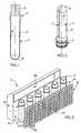
Figure 1 is a cross-sectional side view showing a preform mounted on a rotary support;Figure 2 is a perspective view showing a preform that has undergone selected heating, a comparatively hotter section being shaded grey;Figure 3 is a perspective view showing a heater within which the preforms are run;Figure 4 is a cross-sectional side view of the device ofFigure 3 ;Figure 5 is a cross-sectional view, in the plane of section V-V, of the device ofFigure 4 , in which a heating profile of sinusoidal type has been shown; andFigure 6 is a view similar toFigure 5 , which illustrates a variant in which the heating profile is of the crenellated type.Figure 1 shows in cross section apreform 1 which, in order to be heated on the run within anoven 2, is mounted on a rotary gripping device3 (called a spinner) fastened to a chain driven so as to move at a constant linear speed.- The
preform 1, made of a thermoplastic such as polyethylene terephthalate (PET), is intended, after having been softened by heating at a temperature above its glass transition temperature, to undergo a blow moulding or stretch-blow moulding operation in a mould in order to form a container, such as a bottle or a flask. - The
preform 1 has at its upper end aneck 4, which is intended to undergo minimal deformation both during the heating and the subsequent moulding. Fitted into theneck 4 is the lower end of the spinner3, in the form of a finger. - By means of the upper end in the form of a pinion (not shown), the spinner3 engages with a rack placed along the path of the
preform 1. In this way, said preform is rotated about its axis of revolutionA (called the principal axis) with a rotation speed directly proportional to its speed of linear displacement. - The
preform 1 has an approximatelytubular body 5 which terminates, on the opposite side to theneck 4, in abottom 6 in the form of a hemispherical cap. - In
Figure 1 , thepreform 1 is shown with theneck 4 uppermost - it is in this position that it is introduced into theoven 2 and runs past it. InFigure 2 , thepreform 1 is shown with the neck at the bottom, in order to show on it an angular sector7 (shaded grey) subjected in theoven 2 to selective heating, Thissector 7 along a principal axisA along thebody 5 and on thebottom 6 of thepreform 1 as far as the lower end of the latter. In practice, depending on the applied heating profile, theprofile 1 may compriseseveral sectors 7 subjected to selective heating, for example two diametrically opposed sectors, as will be seen later. - The description now refers to
Figures 3 to 6 . - The
preforms 1 within theoven 2 follow an approximately rectilinear longitudinal pathL (although this may have any type of profile) that extends from the inlet of theoven 2 as far as its outlet. After thepreforms 1 have followed the pathL, they will have been subjected to heating according to a predetermined profile for carrying out the desired blow moulding. - The
oven 2 comprises anenclosure 8 bounded by two facingvertical walls - The
walls body 5 of thepreform 1. In the configuration illustrated, the preform is orientated with aneck 4 uppermost, the latter extending beyond theenclosure 8 above thewalls preform 1 be oriented with theneck 4 downmost. - A
first wall 9, called the emitting wall, is lined with a plurality ofinfrared radiation sources 11 directed towards the inside of theenclosure 8. In practice, each of thesesources 11 takes the form of a laser diode. The diodes are organized so as to form amatrix 12, for example by juxtaposition (and possibly superposition) ofblocks 13 ofdiodes 11, as described in international publicationWO 2006/056673 in the name of the Applicant. - Each
diode 11 emits a beam oriented transversely to the path travelled and lying in a horizontal plane, in such a way that eachdiode 11 contributes to heating an annular portion of eachpreform 1, which runs, at its height, through theoven 2. The angular orientation of thediodes 11 is left up to the person skilled in the art. In particular, thediodes 11 may be pivoted about a vertical axis. - In practice, the
matrix 12 may be produced by the juxtaposition ofblocks 13 oflaser diodes 11 of the type sold by Nuvonyx, eachdiode 11 emitting a flat laser beam with a maximum individual power of 40 W at a wavelength of 940 nm. - According to the embodiment illustrated in
Figures 5 and 6 , the facingwall 10, called the reflector, has a continuous reflecting internal face so that the portion of the radiation emitted by the emittingwall 9, which is not absorbed by thepreforms 1, is reflected thereat onto them. - As illustrated in
Figure4 , theoven 2 may include aventilation box 14, placed behind thereflector 10, thisbox 14 having anopening 15 that opens along the path above theenclosure 8. In thisbox 14 is afan 16 that generates a flow of air expelled transversely through the opening15 so as to cool theneck 4. - Moreover, the
oven 2 is equipped with asystem 17 for regulating the power of thediodes 11 in vertical slices, so as to regulate the intensity of the radiation emitted along the path. This regulation in vertical slices may optionally be combined with regulation in horizontal slices, the intensity of the emitted radiation being regulated parallel to the axisA of thepreforms 1. This regulation is carried out by means of an alternation zonesI1 for emitting more intense radiation and zonesI2 for emitting comparatively less intense radiation, the alternation (i.e. the distance between two more intense radiation zonesI1) being equal to or less than the distance travelled by thepreform 1 during one complete rotation about its axisA. - In this way, the sector or
sectors 7 of thepreform 1 passing in succession past the zonesI1 are subjected to more intense radiation than the sectors passing in front of the zonesI2. Thesectors 7 are therefore heated selectively, that is to say at a higher temperature. - It should be noted that although, from the standpoint of the
preform 1, the radiation to which it is subjected varies in intensity as it moves through theoven 2, from the standpoint of theoven 2 the intensity of the radiation is substantially invariant over time, eachsource 11 emitting radiation of constant intensity. - The heating profile, that is to say the profile of the intensity of the radiation along the path, is defined according to the final shape that it is desired to give the container and according to the distribution profile of the material in said container.
- Two examples are illustrated in
Figures 5 and 6 which make it possible to heat thepreforms 1 selectively so as to heat, to a comparatively hotter temperature, two diametrically opposed sectors, 7a, 7b, which lie along the principal axis A of the preform on thebody 5 and thebottom 6 where a predefined angular spread. - For this purpose, according to a personal embodiment illustrated in
Figure 5 , the heating profile is of sinusoidal shape along the path. Shown inFigure 5 in the form of arrows is the intensity of eachdiode 11 belonging to one and the samevertical block 13. Shown by the sinusoidal continuous line is the envelope of the intensity of the radiation, joining (with smoothing) the ends of the arrows. Shown similarly is the intensity of the radiation reflected by thereflector 10, noting that the intensity of the reflected radiation is comparatively lower than the intensity of the emitted radiation, owing to the absorption by thepreforms 1 of part of this radiation. - It will readily be understood, that, in order for the same portions of the
preforms 1 to be heated selectively along the path, the intensity of the emitted radiation has a periodic character (that is to say that the alternation defined above is approximately constant), although the value of the intensity at the intensity peaks can vary along the path (inFigure 5 , the intensity at the peaks is shown constant). The period is a function of the distance travelled by thepreform 1 or a rotation about its axisA through a predetermined angle. This angle is chosen according to the angular position of thesector 7 that it is desired to subject to selected heating. It will be recalled that each point located on the circumference of thepreform 1 describes a cycloid, the period of which is equal to the distance travelled by thepreform 1 for one complete revolution about its axisA. - In order to selectively heat two diametrically
opposed sectors hotter sectors preform 1 to 180° about its axisA. As regards the intermediate sectors, which are comparatively cooler, these are exposed to the intensity troughs at each rotation of thepreform 1 through 180° about its axisA, but with a phase shift of one quarter of a revolution relative to the comparativelyhotter sectors - According to a second embodiment, illustrated in
Figure 6 , the heating profile is also periodic along the path, but it has a crenellated profile. To obtain such a heating profile, there is an alternation on the emittingwall 9 of trains ofdiodes 11 emitting relatively intense radiation and trains ofdiodes 11 emitting comparatively less intense radiation. The period of the signal is chosen in the same way as previously. The effect obtained is similar, although in this case the transition between the comparatively hotter zones and the comparatively cooler zones is more abrupt. - The
preforms 1 thus heated are then transferred to a moulding unit so as to be formed therein. The comparativelyhotter sections preform 1 makes it possible to obtain a container of complex shape, for example a container having a flattened (for example oval or rectangular) cross section, the comparativelyhotter sectors - By varying the intensity of the emitted radiation, some of the energy usually radiated has a pure loss is saved. Thanks to this regulation, it also possible to delimit the comparatively
hotter sectors - The embodiments described above are not limiting as regards the heating profiles that can be envisaged.
- Thus, it is possible to adapt the radiation profile, for example by regulating the respective values of the intensity peaks and troughs, as well as their intermediate values. A continuously variable profile may be chosen, that is to say one with soft transitions between the peaks and troughs, as in the sinusoidal case described above, or on the contrary a broken profile, for example a crenellated (see above) or triangular profile.
- It is also possible to choose to have radiation emitted with a period adapted to the desired heating profile.
- Thus, it is possible for only a single angular portion of the
preform 1 to be selectively heated. For this purpose, the period will be set to the period of the cycloid described by this portion, which portion will be periodically exposed to an intensity peak of the radiation for each complete revolution (360°) of thepreform 1 about its principal axisA. - Similarly, to obtain three comparatively hotter portions distributed at 120°, the period of the intensity of the radiation will be set to one third of the period of the cycloid.
- In both cases, it may prove necessary to modify the structure of the
oven 2 so as to limit or even eliminate the reflected part of the radiation that contributes to approximately symmetrical heating of thepreform 1. - Likewise, the intensity of the peaks (or hollows) may be varied along the path, for example so that the intensity of the radiation emitted in the peaks increases (or on the contrary decreases).
- Several solutions can be envisaged: the
wall 10 may be coated with an absorbent coating (such as a paint); it may be sufficiently far from thepreforms 1 so that the reflected radiation is largely dissipated; or else it is even possible for thewall 10 to be completely eliminated. However, the latter solution is not the preference of the inventors, because of the potential danger that unconfined infrared radiation may represent.
Claims (13)
- Method of heating a plastic preform (1) for the manufacture of a container by forming it from the preform (1), this method comprising:- a step of transporting the preform (1) along a predetermined path with rotation of the preform (1) about its axis (A); and- a step of heating the preform (1) along said path by means of infrared radiation sources (11),the method beingcharacterized in that the intensity of the emitted radiation is regulated along the path so as to heat selectively at least one angular section (7, 7a, 7b) of the preform (1).
- Heating method according to Claim 1, wherein the regulation is carried out by means of an alternation of zones (I1) that emit more intense radiation and zones(I2) that emit comparatively less intense radiation.
- Heating method according to Claim 2, wherein the alternation is equal to or less than the distance travelled by the preform (1) during one complete rotation about its axis.
- Heating method according to one of Claims 1 to 3, wherein the intensity of the radiation is periodic along the path.
- Heating method according to Claim 4, wherein the period of the intensity of the radiation is equal or approximately equal to the distance travelled by the preform (1) for a rotation of a half-revolution about its axis (A).
- Heating method according to Claim 4, wherein the period of the intensity of the radiation is equal or approximately equal to the distance travelled by the preform (1) for a rotation of one revolution about its axis (A).
- Heating method according to one of Claims 1 to 6, wherein the intensity of the radiation has a continuously variable profile along the path.
- Heating method according to one of Claims 1 to 7, wherein the intensity of the radiation has an approximately sinusoidal profile along the path.
- Heating method according to one of Claims 1 to 8, wherein the intensity of the radiation has an approximately crenellated profile along the path.
- Heating method according to one of Claims 1 to 9, wherein the infrared radiation sources are laser diodes.
- Heater device for heating plastic preforms (1) for the manufacture of containers by forming them from said preforms (1), which comprises:- means for transporting the preforms (1) along a predetermined path;- rotary means (3) for gripping the preforms (1) along said path; and- heating means comprising infrared radiation sources (11) placed along said path,wherein the heater device further comprises:- means for regulating the intensity of the radiation emitted by the sources (11) along said path so as to heat selectively at least one angular section (7, 7a, 7b) of the preform (1).
- Heater according to Claim 11, wherein the infrared radiation sources (11) are laser diodes.
- Heater according to Claim 11 or 12, wherein the infrared radiation sources (11) are arranged in a matrix.
Applications Claiming Priority (2)
| Application Number | Priority Date | Filing Date | Title |
|---|---|---|---|
| FR0703003AFR2915418B1 (en) | 2007-04-25 | 2007-04-25 | METHOD OF HEATING REELIES FOR THE MANUFACTURE OF CONTAINERS |
| PCT/IB2008/001251WO2008132603A1 (en) | 2007-04-25 | 2008-04-22 | Method of heating preforms for the manufacture of containers, and heater device |
Publications (2)
| Publication Number | Publication Date |
|---|---|
| EP2139667A1 EP2139667A1 (en) | 2010-01-06 |
| EP2139667B1true EP2139667B1 (en) | 2013-06-05 |
Family
ID=38792007
Family Applications (1)
| Application Number | Title | Priority Date | Filing Date |
|---|---|---|---|
| EP08750985.7AActiveEP2139667B1 (en) | 2007-04-25 | 2008-04-22 | Method of heating preforms for the manufacture of containers, and heater device |
Country Status (7)
| Country | Link |
|---|---|
| US (1) | US9296148B2 (en) |
| EP (1) | EP2139667B1 (en) |
| JP (1) | JP5337998B2 (en) |
| CN (1) | CN101668624B (en) |
| FR (1) | FR2915418B1 (en) |
| MX (1) | MX2009011393A (en) |
| WO (1) | WO2008132603A1 (en) |
Families Citing this family (32)
| Publication number | Priority date | Publication date | Assignee | Title |
|---|---|---|---|---|
| FR2878185B1 (en)* | 2004-11-22 | 2008-11-07 | Sidel Sas | PROCESS FOR MANUFACTURING CONTAINERS COMPRISING A HEATING STEP BY MEANS OF A COHERENT ELECTROMAGNETIC RADIATION BEAM |
| US10857722B2 (en) | 2004-12-03 | 2020-12-08 | Pressco Ip Llc | Method and system for laser-based, wavelength specific infrared irradiation treatment |
| US7425296B2 (en) | 2004-12-03 | 2008-09-16 | Pressco Technology Inc. | Method and system for wavelength specific thermal irradiation and treatment |
| US10687391B2 (en)* | 2004-12-03 | 2020-06-16 | Pressco Ip Llc | Method and system for digital narrowband, wavelength specific cooking, curing, food preparation, and processing |
| FR2913210B1 (en)* | 2007-03-02 | 2009-05-29 | Sidel Participations | IMPROVEMENTS IN THE HEATING OF PLASTIC MATERIALS BY INFRARED RADIATION |
| FR2917005B1 (en)* | 2007-06-11 | 2009-08-28 | Sidel Participations | HEATING FACILITY FOR PREFORMING BODIES FOR BLOWING CONTAINERS |
| EP2421690B1 (en)* | 2009-04-21 | 2018-03-21 | Koninklijke Philips N.V. | Heating system and method of heating a body of a preform |
| DE102009025839A1 (en) | 2009-05-19 | 2010-11-25 | Krones Ag | Method and tempering device for heating preforms prior to their transformation into containers |
| FR2954920B1 (en) | 2010-01-06 | 2012-08-10 | Sidel Participations | UNIT FOR PROCESSING HOLLOW BODY LAMPS, EQUIPPED WITH A CHAMBER FORMING A LIGHT TRAP |
| FR2957294B1 (en) | 2010-03-10 | 2012-04-20 | Sidel Participations | UNIT FOR TREATMENT OF RADIATION HOLLOW BODIES, EQUIPPED WITH A RADIATION CONTAINMENT SAS |
| DE102010028042A1 (en)* | 2010-04-21 | 2011-10-27 | Krones Ag | Device for thermal conditioning of preform in stretching blow machine that is utilized for manufacturing plastic container for beverage items, has transport apparatus designed such that spacing of preform to heating elements is varied |
| BR112012028574A2 (en)* | 2010-05-07 | 2019-09-24 | Pressco Ip Llc | corner cube irradiation control |
| FR2965505B1 (en)* | 2010-09-30 | 2014-02-14 | Sidel Participations | PROCESS FOR FORMING A CONTAINER WITH AN IMPRESSION ON AN OVERHEATED AREA |
| GB201114048D0 (en)* | 2011-08-16 | 2011-09-28 | Intrinsiq Materials Ltd | Curing system |
| FR2982790B1 (en)* | 2011-11-21 | 2014-03-14 | Sidel Participations | UNIT FOR THERMAL TREATMENT OF REFLECTIVE PLUGS WITH QUADRING DOUBLE-THREADED WALLS |
| ITBO20110691A1 (en)* | 2011-12-02 | 2013-06-03 | Ativa | LINE AND PROCESS OF BOTTLING IN CONTINUOUS CYCLE OF CONTAINERS IN THERMOPLASTIC MATERIAL. |
| CN104936874B (en)* | 2012-12-03 | 2017-09-22 | 伊莫拉Sacmi机械合作公司 | Storage system for storing objects of plastic material processed in filling lines |
| JP5937524B2 (en)* | 2013-02-01 | 2016-06-22 | アイシン高丘株式会社 | Infrared furnace, infrared heating method, and steel plate manufactured using the same |
| JP2016516616A (en)* | 2013-05-02 | 2016-06-09 | コーニンクレッカ フィリップス エヌ ヴェKoninklijke Philips N.V. | Heating system for PET preform |
| FR3018724B1 (en)* | 2014-03-19 | 2016-12-09 | Sidel Participations | PLATFORM TREATMENT UNIT EQUIPPED WITH CONVERGENT WALL OPTICAL CONTAINMENT SECTION |
| DE102014006275A1 (en)* | 2014-05-02 | 2015-11-19 | Khs Corpoplast Gmbh | Method and device for tempering preforms |
| DE102015005769A1 (en)* | 2015-05-08 | 2016-11-10 | Henkel Ag & Co. Kgaa | Process for the inhomogeneous temperature control of preforms |
| FR3049489B1 (en)* | 2016-04-05 | 2018-04-13 | Sidel Participations | METHOD FOR PREFERENTIALLY HEATING A HOLLOW BODY COMPRISING A MARKING STEP |
| FR3070299B1 (en)* | 2017-08-28 | 2019-08-16 | Sidel Participations | THERMAL CONDITIONING UNIT AND METHOD INCLUDING PROGRESSIVE IGNITION IGNITORS |
| IT201800003400A1 (en)* | 2018-03-09 | 2019-09-09 | Smi Spa | PREFORM OVEN |
| FR3097796A1 (en)* | 2019-06-25 | 2021-01-01 | Sidel Participations | Hollow body heating unit for plastic container manufacturing machine |
| CN110605843A (en)* | 2019-07-05 | 2019-12-24 | 广州达意隆包装机械股份有限公司 | An adjustable structure of a preform heating lamp tube and a preform heating mechanism |
| US12377599B2 (en) | 2020-08-03 | 2025-08-05 | Societe Des Produits Nestle S.A. | Method for heating a preform and corresponding method for forming a container |
| CN116157249A (en)* | 2020-08-03 | 2023-05-23 | 雀巢产品有限公司 | Method for heating preforms and corresponding method for forming containers |
| US20230271373A1 (en)* | 2020-08-03 | 2023-08-31 | Societe Des Produits Nestle S.A. | Method for heating a preform and corresponding method for forming a container |
| IT202100008870A1 (en)* | 2021-04-09 | 2022-10-09 | Smi Spa | PREFORM HEATING SYSTEM |
| EP4596203A1 (en)* | 2024-02-01 | 2025-08-06 | Wella Germany GmbH | A round plastic bottle for cosmetic compositions |
Family Cites Families (12)
| Publication number | Priority date | Publication date | Assignee | Title |
|---|---|---|---|---|
| JPS5852912Y2 (en)* | 1980-05-24 | 1983-12-02 | 東洋製罐株式会社 | parison heating device |
| FR2703944B1 (en) | 1993-04-15 | 1995-06-23 | Sidel Sa | Method and installation for the heat treatment of the body of a preform of thermoplastic material. |
| JP3420365B2 (en)* | 1994-12-22 | 2003-06-23 | 株式会社フロンティア | Blow molding equipment |
| FR2732924B1 (en)* | 1995-04-12 | 1997-06-13 | Sidel Sa | METHOD AND DEVICE FOR SELECTIVE HEATING OF A CONTAINER PREFORM |
| JP3924082B2 (en)* | 1998-10-22 | 2007-06-06 | 大成化工株式会社 | Method for producing flat bottle by cold parison blow molding method, and parison for cold parison blow molding |
| JP4637345B2 (en)* | 2000-12-05 | 2011-02-23 | 日精エー・エス・ビー機械株式会社 | Preform heating device |
| DE10121160A1 (en)* | 2001-04-30 | 2002-10-31 | Sig Corpoplast Gmbh & Co Kg | Method and device for tempering preforms |
| FR2856626A1 (en)* | 2003-06-25 | 2004-12-31 | Newtec Internat Group | SYSTEM FOR THERMALLY CONDITIONING PREFORM OF CONTAINERS IN PLASTIC MATERIAL |
| CN2642501Y (en)* | 2003-09-16 | 2004-09-22 | 湖南千山制药机械股份有限公司 | Movable bottle base heating device |
| US7823366B2 (en)* | 2003-10-07 | 2010-11-02 | Douglas Machine, Inc. | Apparatus and method for selective processing of materials with radiant energy |
| FR2878185B1 (en) | 2004-11-22 | 2008-11-07 | Sidel Sas | PROCESS FOR MANUFACTURING CONTAINERS COMPRISING A HEATING STEP BY MEANS OF A COHERENT ELECTROMAGNETIC RADIATION BEAM |
| US7425296B2 (en)* | 2004-12-03 | 2008-09-16 | Pressco Technology Inc. | Method and system for wavelength specific thermal irradiation and treatment |
- 2007
- 2007-04-25FRFR0703003Apatent/FR2915418B1/ennot_activeExpired - Fee Related
- 2008
- 2008-04-22CNCN200880013532.1Apatent/CN101668624B/enactiveActive
- 2008-04-22MXMX2009011393Apatent/MX2009011393A/enactiveIP Right Grant
- 2008-04-22USUS12/596,803patent/US9296148B2/ennot_activeExpired - Fee Related
- 2008-04-22WOPCT/IB2008/001251patent/WO2008132603A1/enactiveApplication Filing
- 2008-04-22EPEP08750985.7Apatent/EP2139667B1/enactiveActive
- 2008-04-22JPJP2010504902Apatent/JP5337998B2/ennot_activeExpired - Fee Related
Also Published As
| Publication number | Publication date |
|---|---|
| US20100127435A1 (en) | 2010-05-27 |
| WO2008132603A1 (en) | 2008-11-06 |
| MX2009011393A (en) | 2010-02-09 |
| EP2139667A1 (en) | 2010-01-06 |
| JP5337998B2 (en) | 2013-11-06 |
| FR2915418A1 (en) | 2008-10-31 |
| JP2010524742A (en) | 2010-07-22 |
| FR2915418B1 (en) | 2012-11-16 |
| CN101668624A (en) | 2010-03-10 |
| US9296148B2 (en) | 2016-03-29 |
| CN101668624B (en) | 2014-03-19 |
Similar Documents
| Publication | Publication Date | Title |
|---|---|---|
| EP2139667B1 (en) | Method of heating preforms for the manufacture of containers, and heater device | |
| US8303290B2 (en) | Method and installation for the production of containers | |
| JP6176459B2 (en) | Method for heating preformed body of container having low outer wall temperature and heating unit for preformed body | |
| US10493686B2 (en) | Oven for the thermal conditioning of preforms and control method of an air cooling device fitted to such an oven | |
| CN101804692B (en) | Device for heating plastic preforms | |
| KR960702377A (en) | Heat treatment method and apparatus for preform or intermediate stage actuator composed of thermoplastic material | |
| CN102233667B (en) | Heating device with surface cooling for pre-forms | |
| MXPA02008015A (en) | HEATER ASSEMBLY FOR MOLDABLE PLASTIC PREFORMS BY BLOW. | |
| EP2964446B1 (en) | Heating system for pet-preforms | |
| EP2477798B1 (en) | Method of heating a preform, a driving arrangement and a preform heating system | |
| US9004896B2 (en) | Oven for plastic preforms with partly transparent radiator | |
| EP2483046B1 (en) | Arrangement of a counter reflector device for use in heating an object, installation and method of heating | |
| CN207327572U (en) | Equipment for heating plastic preforms | |
| CN106536160B (en) | Heating device for heating a hollow body comprising a low-temperature cavity | |
| CN104149322A (en) | Equipment for infrared heating of plastic preform | |
| JP4142998B2 (en) | Preform heating device | |
| JP4059129B2 (en) | Heat crystallization equipment for saturated polyester hollow body | |
| PL243165B1 (en) | Method of heating PET preforms in the process of producing containers, in particular bottles, and an oven for using the method |
Legal Events
| Date | Code | Title | Description |
|---|---|---|---|
| PUAI | Public reference made under article 153(3) epc to a published international application that has entered the european phase | Free format text:ORIGINAL CODE: 0009012 | |
| 17P | Request for examination filed | Effective date:20091013 | |
| AK | Designated contracting states | Kind code of ref document:A1 Designated state(s):AT BE BG CH CY CZ DE DK EE ES FI FR GB GR HR HU IE IS IT LI LT LU LV MC MT NL NO PL PT RO SE SI SK TR | |
| 17Q | First examination report despatched | Effective date:20100126 | |
| DAX | Request for extension of the european patent (deleted) | ||
| GRAP | Despatch of communication of intention to grant a patent | Free format text:ORIGINAL CODE: EPIDOSNIGR1 | |
| GRAS | Grant fee paid | Free format text:ORIGINAL CODE: EPIDOSNIGR3 | |
| GRAA | (expected) grant | Free format text:ORIGINAL CODE: 0009210 | |
| AK | Designated contracting states | Kind code of ref document:B1 Designated state(s):AT BE BG CH CY CZ DE DK EE ES FI FR GB GR HR HU IE IS IT LI LT LU LV MC MT NL NO PL PT RO SE SI SK TR | |
| REG | Reference to a national code | Ref country code:GB Ref legal event code:FG4D | |
| REG | Reference to a national code | Ref country code:CH Ref legal event code:EP | |
| REG | Reference to a national code | Ref country code:AT Ref legal event code:REF Ref document number:615388 Country of ref document:AT Kind code of ref document:T Effective date:20130615 | |
| REG | Reference to a national code | Ref country code:IE Ref legal event code:FG4D | |
| REG | Reference to a national code | Ref country code:DE Ref legal event code:R096 Ref document number:602008025162 Country of ref document:DE Effective date:20130801 | |
| REG | Reference to a national code | Ref country code:AT Ref legal event code:MK05 Ref document number:615388 Country of ref document:AT Kind code of ref document:T Effective date:20130605 | |
| PG25 | Lapsed in a contracting state [announced via postgrant information from national office to epo] | Ref country code:SE Free format text:LAPSE BECAUSE OF FAILURE TO SUBMIT A TRANSLATION OF THE DESCRIPTION OR TO PAY THE FEE WITHIN THE PRESCRIBED TIME-LIMIT Effective date:20130605 Ref country code:LT Free format text:LAPSE BECAUSE OF FAILURE TO SUBMIT A TRANSLATION OF THE DESCRIPTION OR TO PAY THE FEE WITHIN THE PRESCRIBED TIME-LIMIT Effective date:20130605 Ref country code:FI Free format text:LAPSE BECAUSE OF FAILURE TO SUBMIT A TRANSLATION OF THE DESCRIPTION OR TO PAY THE FEE WITHIN THE PRESCRIBED TIME-LIMIT Effective date:20130605 Ref country code:GR Free format text:LAPSE BECAUSE OF FAILURE TO SUBMIT A TRANSLATION OF THE DESCRIPTION OR TO PAY THE FEE WITHIN THE PRESCRIBED TIME-LIMIT Effective date:20130906 Ref country code:NO Free format text:LAPSE BECAUSE OF FAILURE TO SUBMIT A TRANSLATION OF THE DESCRIPTION OR TO PAY THE FEE WITHIN THE PRESCRIBED TIME-LIMIT Effective date:20130905 Ref country code:SI Free format text:LAPSE BECAUSE OF FAILURE TO SUBMIT A TRANSLATION OF THE DESCRIPTION OR TO PAY THE FEE WITHIN THE PRESCRIBED TIME-LIMIT Effective date:20130605 Ref country code:AT Free format text:LAPSE BECAUSE OF FAILURE TO SUBMIT A TRANSLATION OF THE DESCRIPTION OR TO PAY THE FEE WITHIN THE PRESCRIBED TIME-LIMIT Effective date:20130605 Ref country code:ES Free format text:LAPSE BECAUSE OF FAILURE TO SUBMIT A TRANSLATION OF THE DESCRIPTION OR TO PAY THE FEE WITHIN THE PRESCRIBED TIME-LIMIT Effective date:20130916 | |
| REG | Reference to a national code | Ref country code:NL Ref legal event code:VDEP Effective date:20130605 | |
| REG | Reference to a national code | Ref country code:LT Ref legal event code:MG4D | |
| PG25 | Lapsed in a contracting state [announced via postgrant information from national office to epo] | Ref country code:HR Free format text:LAPSE BECAUSE OF FAILURE TO SUBMIT A TRANSLATION OF THE DESCRIPTION OR TO PAY THE FEE WITHIN THE PRESCRIBED TIME-LIMIT Effective date:20130605 Ref country code:PL Free format text:LAPSE BECAUSE OF FAILURE TO SUBMIT A TRANSLATION OF THE DESCRIPTION OR TO PAY THE FEE WITHIN THE PRESCRIBED TIME-LIMIT Effective date:20130605 Ref country code:BG Free format text:LAPSE BECAUSE OF FAILURE TO SUBMIT A TRANSLATION OF THE DESCRIPTION OR TO PAY THE FEE WITHIN THE PRESCRIBED TIME-LIMIT Effective date:20130905 | |
| PG25 | Lapsed in a contracting state [announced via postgrant information from national office to epo] | Ref country code:LV Free format text:LAPSE BECAUSE OF FAILURE TO SUBMIT A TRANSLATION OF THE DESCRIPTION OR TO PAY THE FEE WITHIN THE PRESCRIBED TIME-LIMIT Effective date:20130605 | |
| PG25 | Lapsed in a contracting state [announced via postgrant information from national office to epo] | Ref country code:BE Free format text:LAPSE BECAUSE OF FAILURE TO SUBMIT A TRANSLATION OF THE DESCRIPTION OR TO PAY THE FEE WITHIN THE PRESCRIBED TIME-LIMIT Effective date:20130605 Ref country code:CZ Free format text:LAPSE BECAUSE OF FAILURE TO SUBMIT A TRANSLATION OF THE DESCRIPTION OR TO PAY THE FEE WITHIN THE PRESCRIBED TIME-LIMIT Effective date:20130605 Ref country code:SK Free format text:LAPSE BECAUSE OF FAILURE TO SUBMIT A TRANSLATION OF THE DESCRIPTION OR TO PAY THE FEE WITHIN THE PRESCRIBED TIME-LIMIT Effective date:20130605 Ref country code:IS Free format text:LAPSE BECAUSE OF FAILURE TO SUBMIT A TRANSLATION OF THE DESCRIPTION OR TO PAY THE FEE WITHIN THE PRESCRIBED TIME-LIMIT Effective date:20131005 Ref country code:PT Free format text:LAPSE BECAUSE OF FAILURE TO SUBMIT A TRANSLATION OF THE DESCRIPTION OR TO PAY THE FEE WITHIN THE PRESCRIBED TIME-LIMIT Effective date:20131007 Ref country code:EE Free format text:LAPSE BECAUSE OF FAILURE TO SUBMIT A TRANSLATION OF THE DESCRIPTION OR TO PAY THE FEE WITHIN THE PRESCRIBED TIME-LIMIT Effective date:20130605 | |
| PG25 | Lapsed in a contracting state [announced via postgrant information from national office to epo] | Ref country code:NL Free format text:LAPSE BECAUSE OF FAILURE TO SUBMIT A TRANSLATION OF THE DESCRIPTION OR TO PAY THE FEE WITHIN THE PRESCRIBED TIME-LIMIT Effective date:20130605 Ref country code:RO Free format text:LAPSE BECAUSE OF FAILURE TO SUBMIT A TRANSLATION OF THE DESCRIPTION OR TO PAY THE FEE WITHIN THE PRESCRIBED TIME-LIMIT Effective date:20130605 | |
| PLBE | No opposition filed within time limit | Free format text:ORIGINAL CODE: 0009261 | |
| STAA | Information on the status of an ep patent application or granted ep patent | Free format text:STATUS: NO OPPOSITION FILED WITHIN TIME LIMIT | |
| PG25 | Lapsed in a contracting state [announced via postgrant information from national office to epo] | Ref country code:DK Free format text:LAPSE BECAUSE OF FAILURE TO SUBMIT A TRANSLATION OF THE DESCRIPTION OR TO PAY THE FEE WITHIN THE PRESCRIBED TIME-LIMIT Effective date:20130605 | |
| 26N | No opposition filed | Effective date:20140306 | |
| REG | Reference to a national code | Ref country code:DE Ref legal event code:R097 Ref document number:602008025162 Country of ref document:DE Effective date:20140306 | |
| PG25 | Lapsed in a contracting state [announced via postgrant information from national office to epo] | Ref country code:LU Free format text:LAPSE BECAUSE OF FAILURE TO SUBMIT A TRANSLATION OF THE DESCRIPTION OR TO PAY THE FEE WITHIN THE PRESCRIBED TIME-LIMIT Effective date:20140422 Ref country code:MC Free format text:LAPSE BECAUSE OF FAILURE TO SUBMIT A TRANSLATION OF THE DESCRIPTION OR TO PAY THE FEE WITHIN THE PRESCRIBED TIME-LIMIT Effective date:20130605 | |
| REG | Reference to a national code | Ref country code:CH Ref legal event code:PL | |
| GBPC | Gb: european patent ceased through non-payment of renewal fee | Effective date:20140422 | |
| REG | Reference to a national code | Ref country code:IE Ref legal event code:MM4A | |
| PG25 | Lapsed in a contracting state [announced via postgrant information from national office to epo] | Ref country code:GB Free format text:LAPSE BECAUSE OF NON-PAYMENT OF DUE FEES Effective date:20140422 Ref country code:CH Free format text:LAPSE BECAUSE OF NON-PAYMENT OF DUE FEES Effective date:20140430 Ref country code:LI Free format text:LAPSE BECAUSE OF NON-PAYMENT OF DUE FEES Effective date:20140430 | |
| PG25 | Lapsed in a contracting state [announced via postgrant information from national office to epo] | Ref country code:IE Free format text:LAPSE BECAUSE OF NON-PAYMENT OF DUE FEES Effective date:20140422 | |
| REG | Reference to a national code | Ref country code:FR Ref legal event code:PLFP Year of fee payment:9 | |
| PG25 | Lapsed in a contracting state [announced via postgrant information from national office to epo] | Ref country code:MT Free format text:LAPSE BECAUSE OF FAILURE TO SUBMIT A TRANSLATION OF THE DESCRIPTION OR TO PAY THE FEE WITHIN THE PRESCRIBED TIME-LIMIT Effective date:20130605 | |
| PG25 | Lapsed in a contracting state [announced via postgrant information from national office to epo] | Ref country code:CY Free format text:LAPSE BECAUSE OF FAILURE TO SUBMIT A TRANSLATION OF THE DESCRIPTION OR TO PAY THE FEE WITHIN THE PRESCRIBED TIME-LIMIT Effective date:20130605 | |
| PG25 | Lapsed in a contracting state [announced via postgrant information from national office to epo] | Ref country code:TR Free format text:LAPSE BECAUSE OF FAILURE TO SUBMIT A TRANSLATION OF THE DESCRIPTION OR TO PAY THE FEE WITHIN THE PRESCRIBED TIME-LIMIT Effective date:20130605 Ref country code:HU Free format text:LAPSE BECAUSE OF FAILURE TO SUBMIT A TRANSLATION OF THE DESCRIPTION OR TO PAY THE FEE WITHIN THE PRESCRIBED TIME-LIMIT; INVALID AB INITIO Effective date:20080422 | |
| REG | Reference to a national code | Ref country code:FR Ref legal event code:PLFP Year of fee payment:10 | |
| REG | Reference to a national code | Ref country code:FR Ref legal event code:PLFP Year of fee payment:11 | |
| P01 | Opt-out of the competence of the unified patent court (upc) registered | Effective date:20230505 | |
| PGFP | Annual fee paid to national office [announced via postgrant information from national office to epo] | Ref country code:FR Payment date:20250319 Year of fee payment:18 | |
| PGFP | Annual fee paid to national office [announced via postgrant information from national office to epo] | Ref country code:IT Payment date:20250319 Year of fee payment:18 | |
| PGFP | Annual fee paid to national office [announced via postgrant information from national office to epo] | Ref country code:DE Payment date:20250319 Year of fee payment:18 |