EP2137526B1 - Method and system for downhole spectroscopic hydrogen sulfide detection - Google Patents
Method and system for downhole spectroscopic hydrogen sulfide detectionDownload PDFInfo
- Publication number
- EP2137526B1 EP2137526B1EP08842567.3AEP08842567AEP2137526B1EP 2137526 B1EP2137526 B1EP 2137526B1EP 08842567 AEP08842567 AEP 08842567AEP 2137526 B1EP2137526 B1EP 2137526B1
- Authority
- EP
- European Patent Office
- Prior art keywords
- detection
- mixture
- formation fluid
- downhole
- hydrogen sulfide
- Prior art date
- Legal status (The legal status is an assumption and is not a legal conclusion. Google has not performed a legal analysis and makes no representation as to the accuracy of the status listed.)
- Not-in-force
Links
Images


Classifications
- G—PHYSICS
- G01—MEASURING; TESTING
- G01N—INVESTIGATING OR ANALYSING MATERIALS BY DETERMINING THEIR CHEMICAL OR PHYSICAL PROPERTIES
- G01N31/00—Investigating or analysing non-biological materials by the use of the chemical methods specified in the subgroup; Apparatus specially adapted for such methods
- G01N31/22—Investigating or analysing non-biological materials by the use of the chemical methods specified in the subgroup; Apparatus specially adapted for such methods using chemical indicators
- G01N31/223—Investigating or analysing non-biological materials by the use of the chemical methods specified in the subgroup; Apparatus specially adapted for such methods using chemical indicators for investigating presence of specific gases or aerosols
- G01N31/224—Investigating or analysing non-biological materials by the use of the chemical methods specified in the subgroup; Apparatus specially adapted for such methods using chemical indicators for investigating presence of specific gases or aerosols for investigating presence of dangerous gases
- C—CHEMISTRY; METALLURGY
- C09—DYES; PAINTS; POLISHES; NATURAL RESINS; ADHESIVES; COMPOSITIONS NOT OTHERWISE PROVIDED FOR; APPLICATIONS OF MATERIALS NOT OTHERWISE PROVIDED FOR
- C09K—MATERIALS FOR MISCELLANEOUS APPLICATIONS, NOT PROVIDED FOR ELSEWHERE
- C09K8/00—Compositions for drilling of boreholes or wells; Compositions for treating boreholes or wells, e.g. for completion or for remedial operations
- C09K8/52—Compositions for preventing, limiting or eliminating depositions, e.g. for cleaning
- E—FIXED CONSTRUCTIONS
- E21—EARTH OR ROCK DRILLING; MINING
- E21B—EARTH OR ROCK DRILLING; OBTAINING OIL, GAS, WATER, SOLUBLE OR MELTABLE MATERIALS OR A SLURRY OF MINERALS FROM WELLS
- E21B49/00—Testing the nature of borehole walls; Formation testing; Methods or apparatus for obtaining samples of soil or well fluids, specially adapted to earth drilling or wells
- E21B49/08—Obtaining fluid samples or testing fluids, in boreholes or wells
- G—PHYSICS
- G01—MEASURING; TESTING
- G01N—INVESTIGATING OR ANALYSING MATERIALS BY DETERMINING THEIR CHEMICAL OR PHYSICAL PROPERTIES
- G01N21/00—Investigating or analysing materials by the use of optical means, i.e. using sub-millimetre waves, infrared, visible or ultraviolet light
- G01N21/75—Systems in which material is subjected to a chemical reaction, the progress or the result of the reaction being investigated
- G01N21/77—Systems in which material is subjected to a chemical reaction, the progress or the result of the reaction being investigated by observing the effect on a chemical indicator
- C—CHEMISTRY; METALLURGY
- C09—DYES; PAINTS; POLISHES; NATURAL RESINS; ADHESIVES; COMPOSITIONS NOT OTHERWISE PROVIDED FOR; APPLICATIONS OF MATERIALS NOT OTHERWISE PROVIDED FOR
- C09K—MATERIALS FOR MISCELLANEOUS APPLICATIONS, NOT PROVIDED FOR ELSEWHERE
- C09K2208/00—Aspects relating to compositions of drilling or well treatment fluids
- C09K2208/20—Hydrogen sulfide elimination
- G—PHYSICS
- G01—MEASURING; TESTING
- G01N—INVESTIGATING OR ANALYSING MATERIALS BY DETERMINING THEIR CHEMICAL OR PHYSICAL PROPERTIES
- G01N21/00—Investigating or analysing materials by the use of optical means, i.e. using sub-millimetre waves, infrared, visible or ultraviolet light
- G01N21/75—Systems in which material is subjected to a chemical reaction, the progress or the result of the reaction being investigated
- G01N21/77—Systems in which material is subjected to a chemical reaction, the progress or the result of the reaction being investigated by observing the effect on a chemical indicator
- G01N2021/7756—Sensor type
- G01N2021/7763—Sample through flow
- G—PHYSICS
- G01—MEASURING; TESTING
- G01N—INVESTIGATING OR ANALYSING MATERIALS BY DETERMINING THEIR CHEMICAL OR PHYSICAL PROPERTIES
- G01N21/00—Investigating or analysing materials by the use of optical means, i.e. using sub-millimetre waves, infrared, visible or ultraviolet light
- G01N21/75—Systems in which material is subjected to a chemical reaction, the progress or the result of the reaction being investigated
- G01N21/77—Systems in which material is subjected to a chemical reaction, the progress or the result of the reaction being investigated by observing the effect on a chemical indicator
- G01N2021/7769—Measurement method of reaction-produced change in sensor
- G01N2021/7773—Reflection
- G—PHYSICS
- G01—MEASURING; TESTING
- G01N—INVESTIGATING OR ANALYSING MATERIALS BY DETERMINING THEIR CHEMICAL OR PHYSICAL PROPERTIES
- G01N21/00—Investigating or analysing materials by the use of optical means, i.e. using sub-millimetre waves, infrared, visible or ultraviolet light
- G01N21/75—Systems in which material is subjected to a chemical reaction, the progress or the result of the reaction being investigated
- G01N21/77—Systems in which material is subjected to a chemical reaction, the progress or the result of the reaction being investigated by observing the effect on a chemical indicator
- G01N2021/7769—Measurement method of reaction-produced change in sensor
- G01N2021/7786—Fluorescence
- G—PHYSICS
- G01—MEASURING; TESTING
- G01N—INVESTIGATING OR ANALYSING MATERIALS BY DETERMINING THEIR CHEMICAL OR PHYSICAL PROPERTIES
- G01N21/00—Investigating or analysing materials by the use of optical means, i.e. using sub-millimetre waves, infrared, visible or ultraviolet light
- G01N21/75—Systems in which material is subjected to a chemical reaction, the progress or the result of the reaction being investigated
- G01N21/77—Systems in which material is subjected to a chemical reaction, the progress or the result of the reaction being investigated by observing the effect on a chemical indicator
- G01N21/78—Systems in which material is subjected to a chemical reaction, the progress or the result of the reaction being investigated by observing the effect on a chemical indicator producing a change of colour
- Y—GENERAL TAGGING OF NEW TECHNOLOGICAL DEVELOPMENTS; GENERAL TAGGING OF CROSS-SECTIONAL TECHNOLOGIES SPANNING OVER SEVERAL SECTIONS OF THE IPC; TECHNICAL SUBJECTS COVERED BY FORMER USPC CROSS-REFERENCE ART COLLECTIONS [XRACs] AND DIGESTS
- Y10—TECHNICAL SUBJECTS COVERED BY FORMER USPC
- Y10T—TECHNICAL SUBJECTS COVERED BY FORMER US CLASSIFICATION
- Y10T436/00—Chemistry: analytical and immunological testing
- Y10T436/18—Sulfur containing
- Y10T436/182—Organic or sulfhydryl containing [e.g., mercaptan, hydrogen, sulfide, etc.]
- Y10T436/184—Only hydrogen sulfide
Definitions
- the inventionis generally related to detection and sensing of properties of downhole fluids. More particularly, this patent specification relates to downhole spectroscopic detection of substances such as Hydrogen Sulfide using colloidal detection mixtures.
- Hydrogen sulfideoccurs extensively in a number of subsurface hydrocarbon reservoirs under anaerobic conditions.
- the presence of hydrogen sulfideis highly corrosive to casing, tubing, and other metallic and polymeric tools, an effect that is considerably accelerated by low pH and the presence of carbon dioxide. This has a significant impact on the overall hydrocarbon recovery processes, during which materials selection and corrosion control are of great importance.
- H 2 Sis hazardous to humans even at minute concentration levels (for example, about 100 ppm).
- the H 2 S content of reservoir fluidscan be determined from samples collected by wireline fluid Sampling tools such as Schlumberger's Modular Dynamics Tester or other sampling tools. Fluid samples are usually collected in metal containers, which are able to maintain the pressures at which the samples were collected.
- a problem associated with sampling fluids containing hydrogen sulfideis partial loss of the gas by reaction of the metal components, particularly those made from iron-based metals.
- the hydrogen sulfide gasreadily forms nonvolatile and insoluble metal sulfides by reaction with many metals and metal oxides, and analysis of the fluid samples can therefore give an underestimate of the true sulfide content.
- a method of detecting hydrogen sulfide in a formation fluid downholeis provided.
- a detection mixtureis combined with the formation fluid downhole.
- the detection mixtureincludes metal particles for reacting with hydrogen sulfide forming a metal sulfide, and nanoparticles sized so as to inhibit significant aggregation of the metal sulfide so as to enable spectroscopic detection of the metal sulfide downhole.
- the combined mixture and formation fluidis then spectroscopically interrogated so as to detect the presence of the metal sulfide thereby indicating the presence and/or quantity of hydrogen sulfide in the formation fluid.
- a systemfor spectroscopically detecting hydrogen sulfide downhole.
- the systemincludes a detection mixture as stated above for reacting with hydrogen sulfide, a downhole mixture delivery system for exposing the detection mixture to fluids collected from a subterranean formation in a downhole setting, and an optical detection system for detecting the presence of hydrogen sulfide in the reacted mixture after exposure to the formation fluid.
- the system of the present inventionis defined in claim 1.
- the inventionprovides a method for dispersing a compound which is otherwise insoluble in a solvent into a homogeneous solution for use in spectroscopic analysis of a fluid. This comprises a step of combining the compound with the solvent and nanoparticles, wherein the nanoparticles are sized and charged so as to inhibit significant aggregation which would otherwise hinder spectroscopic analysis of the fluid.
- a mixtureis provided for use in the downhole spectroscopic detection of hydrogen sulfide according to the method of the present invention.
- the mixtureincludes metal particles for reacting with hydrogen sulfide thereby forming a metal sulfide species and nanoparticles sized so as to inhibit significant aggregation of insoluble metal sulfide species so as to enable spectroscopic detection of the metal sulfide species downhole.
- Chelating ligandsare preferably included in the mixture for sustaining thermal endurance of the mixture under downhole conditions.
- the metal particlesare preferably metal ions.
- H 2 SHydrogen sulfide
- mixturescan be provided that have a relatively large surface area onto which the reacting sulfide can precipitate.
- the surface areais provided in the form of particles that are small enough that when optical detection methods can be used, such as with visible light, the precipitated sulfide has the appearance of being a fully solvated, although on a molecular level the sulfide is no longer in the solution phase.
- a specific detection and measurement strategy for hydrogen sulfidecan be provided based on the colorimetric features of metal sulfide species that are dispersed into a homogeneous colloidal dispersion in the presence of an overwhelming amount of silica nanoparticles in an alkaline aqueous medium. For example, a ratio of Si 7000 mM: Pb 2+ 3 mM has been found to be effective in some applications.
- the metal-ligand-silica systemsustains high recovery yield after extensive thermal treatment that is representative of downhole sampling and detecting processes.
- the provided mixturecan be used in combination with a downhole optical detection system, such as Schlumberger's Live Fluid Analyser (LFA), which is operated as part of Schlumberger's openhole logging tool Modular Formation Dynamics Tester (MDT). Accordingly, a viable means for in situ detection and measurement of hydrogen sulfide in the formation gas can be provided.
- a downhole optical detection systemsuch as Schlumberger's Live Fluid Analyser (LFA), which is operated as part of Schlumberger's openhole logging tool Modular Formation Dynamics Tester (MDT).
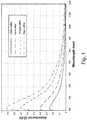
- FIG. 1shows a set of typical visible spectra of a homogeneous colloidal dispersion as used in the method of the invention.
- a mixturecomprising of Pb 2+ /NTA-Ludox® and water reacted with increasingly higher concentrations of sulfide.
- the curvesexhibit a shoulder at around 600 nm and a peak at around 310 nm.
- FIG. 1shows that the sensitivity of the solution is sufficient to detect sulfide concentrations as low as around 3 ppm. Additionally, the proportional growth of the optical density with the sulfide concentration can be used to make quantitative measurements.
- the water insoluble metal sulfideshould be dispersed into homogeneously distributed particles that are small enough to remain in the bulk of the solution. This is preferably achieved via charge matching between the metal species and the silica particles (4).
- Colloidal particlesthat have been found to be suitable for some applications are marketed under the brand name Ludox®, and can be obtained from either GRACE Davison or Sigma-Aldrich.
- the Ludox® particlesare discrete uniform spheres with a diameter of about 22 nm, They have no internal surface area or apparent crystallinity, with an apparent surface area of 150m 2 /g. At a typical pH of 9, the silica particle surface is negatively charged due to deprotonation of its surface silano groups.
- These particlesrepel one another thereby yielding a stable solution, capable of confining the positively charged metal species either in the close proximity of, or directly onto, their surface.
- Such an effecthas been found to be strong enough to prevent the following two adverse processes from happening: (1) precipitation of an otherwise poorly soluble metal hydroxide; and (2) precipitation/aggregation of an otherwise poorly soluble metal sulfide species into micron sized powder.
- Thisallows quantitative analysis of sulfide using absorption spectroscopy without interference from scattering.
- the nanoparticlesshould be sized between about 7nm and 25nm. If the nanoparticles are too small, then the limit of a colloidal particle will be reached. The particles will become fully solvated in water which will result in the charge of the particles not functioning as desired, If the particles are too large, it has been found that the aqueous solution becomes overly milky or opaque so as to impede spectroscopic analysis,
- FIG. 2illustrates a representation of lead species being confined in close proximity, or directly on to the surface of silica nanoparticles.
- lead ion 208is in close proximity to silica nano particles 210, 212, 214 and 216.
- lead sulfide 220is shown in close proximity to silica nanoparticles 210, 212, 214 and 216.
- the confinement of the lead species by the silica nanoparticlescould be a nanocage function or similar to a nanocage as shown in FIG. 2 , However, the arrangement and functioning on the molecular level may not be precisely understood at present.
- the thermal endurance of the reaction systemshould be considered in a temperature regime analogous to the anticipated wellbore conditions.
- a temperature of 150°Cis suitable and is used throughout this description unless otherwise indicated. It was observed that a 24-hour baking of the Pb 2+ -Ludox® binary mixture resulted in a considerably lower yield of optical density as compared to the ambient temperature counterpart. At the end of the baking period, the sample was cooled down to ambient temperature.
- an appropriate chelating ligands to be selectedtends to shield Pb 2+ .
- a particularly effective ligand, nitrilotriacetic acid (NTA)was identified that consistently has the recovery yield in optical density better than 90% after 24 hour baking at 150°C.
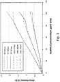
- FIG. 3shows the average values of three independent samples baked at 150°C for 24 hours against respective ambient temperature references
- FIG. 3shows the absorbance versus sulfide concentration relationship at three discrete wavelengths of 815nm, 680nm and 570nm. Each pair compares the ambient temperature sample to its counterpart through baking at 150°C for 24 hours, and then probed at ambient temperature.
- the mixture testedhad the following characteristics: Pb(NO 3 ) 2 4.03 mM, NTA 6.14 mM, Ludox® 35%, pH 9.
- FIG. 3shows that the samples exhibit a nearly 100% recovery yield in optical density in all the three wavelengths at sulfide concentrations up to 89 ppm (with exception for 680 nm at this point).
- the pH of the mixtureshould be carefully selected. If the pH is too low, for example below 7.5, problems can occurs such as gelling of the Ludux® and/or multiple species of H 2 S occurring and the measurement may lose quantification. If the pH is too high, for example above 10.5, the silica particles will start to dissolve in the aqueous solution. Additionally, corrosion of the downhole tool and casing become a problem at high pH levels. It has been found that for many applications a pH range of 9,0-9.5 can be ideal.
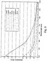
- FIG. 4shows the uncertainty of the data set is presented in FIG. 3 .
- the largest uncertainty at the 7ppm levelwhich is 9.6% representing a possible error of ⁇ 0.67ppm.
- the smallest uncertaintyis at the 89 ppm level, which is 1.9% representing a possible error of ⁇ 1.7 ppm.
- FIG. 5shows four pairs of spectra of a Cd/NTA-Ludox® mixture before and after baking at 150°C for 24 hours, according to an embodiment of the invention.
- the mixture characteristicswere: Cd(NO 3 ) 2 2.5 mM, NTA 5.1 mM, Ludox® 32%, pH 9.
- These spectraexhibit a shoulder at around 430nm, and a peak at 315 nm that red-shift to ⁇ 350nm as a result of baking.
- This cadmium systemalso affords high recovery yield in optical density across the sulfide concentration range from 18 to 71 ppm, representing a viable alternative to lead.
- the critical loading ratiocan be defined herein as the amount (in mM) of metal ions which can be combined with a particular nanoparticle-water weight ratio, beyond which there is a significant risk of a large scale precipitation that destroys the homogeneity of the mixture.
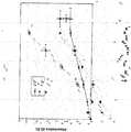
- FIG. 6shows critical loading ratios of mixtures according to embodiments of the invention.
- Ludox® 6shows three domains for aqueous mixtures of Pb 2+ /NTA in Ludox® all after baking at 150°C for 24 hours: (1) below 25%, the Ludox® is not sufficient to accommodate the normal amount of Pb 2+ /NTA; (2) between 32-45%, the Ludox® is functioning fine with [Pb 2+ ] up to 7 mM; and (3) at even higher concentrations, the Ludox® tends to gel as a result of baking. Thus, after being baked at 150°C for 24 hours, a Ludox® concentration greater than 45% makes the mixture liable to gel formation. On the other hand, at Ludox® concentrations lower than 20%, its binding capacity is not strong enough to accommodate the given amount of Pb 2+ /NTA.
- FIG. 7is a table summarizing the results of thermal endurance test of lead coupled with a group of chelating ligands with different binding capacities, according to embodiments of the invention.
- the following abbreviationsare used in FIG. 7 : NTA-nitrilotriacetic acid, CA-citric acid; EDDA-ethylenediamine diacetic acid; IDAA-iminodiacetic acid; PDCA-pyridinediacetic acid; IDMPA-iminodimethyl phosphorous acid.
- NTA and IDMPArepresent two chelating ligands for lead that provide a high level of thermal endurance and remain chemically active to sulfide.
- FIG. 8shows optical absorption curves of various metal sulfides in Ludux®, according to embodiments of the invention.
- Nickel, Copper and Seleniumcan be used for in mixtures for detecting H 2 S, in addition to Lead and Cadmium as described above. Copper and Selenium, in particular, give rise to a specific absorption peak which provides a clear distinction between absorbance due to the particles from scattering and absorbance due to oil or other components.
- other metalssuch as Cobalt, Silver and Tin could be useful in detection mixtures under some circumstances.
- the silica particles in Ludox®are dissolved in water.
- other solventscan be used with the detection mixtures.
- the watercan be replaced by formamide. This is done by the addition of formamide to the Ludox® and heating the solution to about 110 degrees C. The water will evaporate but the silica will remain suspended in the formamide.
- Formamideis an organic polar solvent.
- the silica suspension in formamidecan be used with the detection mixtures as described herein.
- the formamide suspensionoffers some advantages over water. For example, formamide has a boiling point of 220 degrees C which minimizes the risk of evaporation of the solvent.
- silica particles dissolved in formamideare insensitive to the salt concentration whereas the aqueous Ludox® mixture can tend to develop into a gel when in contact with higher concentrations salts.
- Higher loads of lead or other metal particlescan be used with solvents such as formamide since such mixtures have less of tendency to gel.
- one disadvantage of silica particles in formamidecan be a relatively rapid discoloring of the solution in formamide when exposed to sulfide. The coloring tends to disappear with time. Depending on the sulfide concentrations the color completely disappears within a few hours.
- other solventscan be used instead of water or formamide.
- an organic solvent having relatively high polaritycan be suitable, such as dimethylformamide, glycol.
- FIG. 9shows two examples of systems for optically detecting and measuring H 2 S downhole using the mixtures as described herein, FIG. 9 shows an example of a flowline-based H 2 S detection system according to embodiments of the invention.
- the flow line 910carries test fluids from the formation, from the left side of flow line 910 in FIG. 9 , to a borehole or to one or more sampling chambers, on the right side of flow line 910 in FIG.
- the flow line 910receives an amount of a suitable mixture from bottle 912.
- the flow of the mixture stored in bottle 912 into flow line 910is controlled by an electro-mechanical valve 914.
- the mixturemixes with the fluids in the flow line 910 before reaching an interrogation window 920 down-stream.
- Window 920is preferably made from a rugged material such as sapphire to withstand an aggressive flow within flow line 910.
- a light source 916provides light 922 either in a broad spectrum of white light or at an appropriate wavelength (e.g. 815mn, 680nm or 570nm, which is compatible with Schlumberger's LFA system in Schlumberger's MDT). Light 922 enters the flow line 910 via window 920 and illuminates the fluid in flow line 910.
- a suitable filter 926 and lens 928aid in the detection of the signal from flow line 910 through window 920 by optical detector 930.
- Filter 926is designed to only pass a narrow range of frequencies centered around the target wavelength (e.g. 815nm, 680nm or 570nm).
- detector 930measures the optical density at the appropriate wavelength, which is then compared with a predefined calibration curve to establish the existence or determine the quantity of H 2 S in the formation fluid. The described operation is then repeated for every measurement.
- light source 918can be used to provide light 924 into the flow line 910.
- FIG. 9shows the window at one side of the flow line, according to a different embodiment of the invention, the measurement can be made with separated windows for illumination and detection, which can be located at opposite sides of the flow line 910.
- FIG. 10shows according to an aspect of the invention, an example of a sample bottle based H 2 S detection system.
- Sample bottle 1010is housed in a downhole fluid sampling tool (not shown) such as Schlumberger's MDT, Prior to use, sample bottle 1010 is filled with the H 2 S detection mixture as described herein.
- the formation fluidis drawn into the sample bottle 1010 via inlet 1012 by creating an appropriate pressure gradient along the flow line.
- Formation fluid in a gas stateis drawn or bubbled into the sample bottle 1010 thereby exposing the sampled formation fluid to the detection mixture in bottle 1010. Diffusion will act to mix the formation fluid with the detection mixture so as to generate a detectable signal.
- a mixing system 1040can be provided.
- Mixing system 1040can be based on an acoustic transducer, such as described in US Patent No. 6,988,547 , or in US Patent No. 6,758,090 , both incorporated by reference herein.
- Optical detection system 1014is provided on sample bottle 1010 which can be similar to the LFA system in Schlumberger's MDT tool.
- two light sources 1016 and 1018provide light 1022 and 1024 respectively either in a broad spectrum of white light or at an appropriate wavelengths (e.g. 815nm, 680nm and 570nm).
- the signal from sample bottle 1010is detected by light detector 1030 via window 1020, preferably made of sapphire, filter 1026 and lens 1028.
- Filter 1026is designed to only pass a narrow range of frequencies centered around the target wavelength (e.g. 815nm, 680nm or 570nm).
- Detector 1030measures the optical density at the appropriate wavelength, which is then compared with a predefined calibration curve to establish the existence or determine the quantity of H 2 S in the formation fluid.
- the sample bottle 1010is filled with an H 2 S detection mixture, and the formation fluid is drawn into bottle 1010 as described above. However, the combined mixture and formation fluid is then pushed back out into a flow line such as flowline 910 in FIG. 9 where the optical interrogation can occur using a detection system as shown in FIG. 9 .
- optical detection system 1014need not be provided.
- the mixing system 1040can be used to sufficiently mix the detection mixture and the formation fluid. If sufficient mixing occurs by the drawing in and pushing out process of the formation fluid, as well as diffusion in bottle 1010 and flowline 910, then mixing system 1040 need not be used.
- FIG.s 9 and 10show that fluorescence spectroscopy can be used to detect the reacted metal sulfide species in flowline 910 of FIG. 9 or bottle 1010 of FIG. 10 .
- one or more of the light sources 916, 918, 1016 and 1018can be used as an excitation energy source, and the florescence from the metal sulfide species can be detected using filters and detectors 926, 1026 and 930, 1030 respectively.
- Existing downhole fluorescence detection technologycan be used such as used in the Composition Fluid Analyzer module to MDT tester suite provided by Schlumberger. Fluorescence spectroscopy can be especially useful when the concentrations of metal sulfide are relatively high, due to an increased fluorescence signal relative to background noise.
- silica based nanoparticleshave been described in the embodiments herein, alternative materials such alumina (Al 2 O 3 ), titania (TiO 2 ), cerium oxide (CeO 2 ) or other metal oxides can be use for the nanoparticle material.
- uncharged metal particlescan be used instead of ions.
- elemental metal particlescan be manufactured or purchased having a size domain of 5-200 nm and zero surface charge.
Landscapes
- Life Sciences & Earth Sciences (AREA)
- Chemical & Material Sciences (AREA)
- Health & Medical Sciences (AREA)
- Engineering & Computer Science (AREA)
- Physics & Mathematics (AREA)
- General Life Sciences & Earth Sciences (AREA)
- Mining & Mineral Resources (AREA)
- Analytical Chemistry (AREA)
- Biochemistry (AREA)
- General Health & Medical Sciences (AREA)
- General Physics & Mathematics (AREA)
- Immunology (AREA)
- Pathology (AREA)
- Geology (AREA)
- Fluid Mechanics (AREA)
- Toxicology (AREA)
- Plasma & Fusion (AREA)
- Chemical Kinetics & Catalysis (AREA)
- Geochemistry & Mineralogy (AREA)
- Materials Engineering (AREA)
- Organic Chemistry (AREA)
- Environmental & Geological Engineering (AREA)
- Dispersion Chemistry (AREA)
- Biophysics (AREA)
- Molecular Biology (AREA)
- Investigating Or Analysing Materials By Optical Means (AREA)
- Investigating, Analyzing Materials By Fluorescence Or Luminescence (AREA)
- Investigating Or Analysing Materials By The Use Of Chemical Reactions (AREA)
- Investigating Or Analyzing Non-Biological Materials By The Use Of Chemical Means (AREA)
- Analysing Materials By The Use Of Radiation (AREA)
Description
- The invention is generally related to detection and sensing of properties of downhole fluids. More particularly, this patent specification relates to downhole spectroscopic detection of substances such as Hydrogen Sulfide using colloidal detection mixtures.
- Hydrogen sulfide (H2S) occurs extensively in a number of subsurface hydrocarbon reservoirs under anaerobic conditions. The presence of hydrogen sulfide is highly corrosive to casing, tubing, and other metallic and polymeric tools, an effect that is considerably accelerated by low pH and the presence of carbon dioxide. This has a significant impact on the overall hydrocarbon recovery processes, during which materials selection and corrosion control are of great importance. Additionally, H2S is hazardous to humans even at minute concentration levels (for example, about 100 ppm).
- The H2S content of reservoir fluids can be determined from samples collected by wireline fluid Sampling tools such as Schlumberger's Modular Dynamics Tester or other sampling tools. Fluid samples are usually collected in metal containers, which are able to maintain the pressures at which the samples were collected. However, a problem associated with sampling fluids containing hydrogen sulfide is partial loss of the gas by reaction of the metal components, particularly those made from iron-based metals. The hydrogen sulfide gas readily forms nonvolatile and insoluble metal sulfides by reaction with many metals and metal oxides, and analysis of the fluid samples can therefore give an underestimate of the true sulfide content.
- As a result, thein situ detection and measurement of hydrogen sulfide is widely regarded as a critical parameter needed for well completion and production strategies. Due to the high chemical reactivity of sulfide species, various detection strategies including spectroscopy, electrochemistry, chromatography and combinations thereof have been proposed. For example, see Wardencki, W. J. "Problems with the determination of environmental sulphur compounds by gas chromatography" Journal of Chromatography A, VoI 793, 1 (1998).
US patent 6,939,717B2 describes feasible electrochemical and optical methodologies and embodiments aimed at downhole detection of hydrogen sulfide. - In accordance with one aspect of the invention, a method of detecting hydrogen sulfide in a formation fluid downhole is provided. A detection mixture is combined with the formation fluid downhole. The detection mixture includes metal particles for reacting with hydrogen sulfide forming a metal sulfide, and nanoparticles sized so as to inhibit significant aggregation of the metal sulfide so as to enable spectroscopic detection of the metal sulfide downhole. The combined mixture and formation fluid is then spectroscopically interrogated so as to detect the presence of the metal sulfide thereby indicating the presence and/or quantity of hydrogen sulfide in the formation fluid.
- In accordance with another aspect of the invention, a system is provided for spectroscopically detecting hydrogen sulfide downhole. The system includes a detection mixture as stated above for reacting with hydrogen sulfide, a downhole mixture delivery system for exposing the detection mixture to fluids collected from a subterranean formation in a downhole setting, and an optical detection system for detecting the presence of hydrogen sulfide in the reacted mixture after exposure to the formation fluid. The system of the present invention is defined in
claim 1. - It will be appreciated that the invention provides a method for dispersing a compound which is otherwise insoluble in a solvent into a homogeneous solution for use in spectroscopic analysis of a fluid. This comprises a step of combining the compound with the solvent and nanoparticles, wherein the nanoparticles are sized and charged so as to inhibit significant aggregation which would otherwise hinder spectroscopic analysis of the fluid.
- Further features and advantages of the invention will become more readily apparent from the following detailed description when taken in conjunction with the accompanying Drawing,
- The present invention is further described in the detailed description which follows, in reference to the noted plurality of drawings by way of nonlimiting examples of exemplary embodiments of the present invention, in which like reference numerals represent similar parts throughout the several views of the drawings, and wherein:
FIG. 1 shows a set of typical visible spectra of a homogeneous colloidal dispersion;FIG. 2 illustrates a representation of lead species being confined in close proximity, or directly on to the surface of silica nanoparticles;FIG. 3 shows the average values of three independent samples baked at 150°C for 24 hours against respective ambient temperature references;FIG. 4 shows the uncertainty of the data set is presented inFIG. 3 ;FIG. 5 shows four pairs of spectra of a Cd/NTA-Ludox® dispersion before and after baking at 150°C for 24 hours;FIG. 6 shows critical loading ratios of mixtures used in the method of the invention.FIG. 7 is a table summarizing the results of thermal endurance test of lead coupled with a group of chelating ligands with different binding capacities;FIG. 8 shows optical absorption curves of various metal sulfides in Ludux®, according to the detection method of the invention;FIG. 9 shows an example of a flowline-based H2S detection system according to embodiments of the invention; andFIG. 10 shows an example of a sample bottle based H2S detection system according to embodiments of the invention.- The particulars shown herein are by way of example and for purposes of illustrative discussion of the embodiments of the present invention only and are presented in the cause of providing what is believed to be the most useful and readily understood description of the principles and conceptual aspects of the present invention. In this regard, no attempt is made to show structural details of the present invention in more detail than is necessary for the fundamental understanding of the present invention, the description taken with the drawings making apparent to those skilled in the art how the several forms of the present invention may be embodied in practice. Further, like reference numbers and designations in the various drawings indicated like elements.
- A mixture is provided for use in the downhole spectroscopic detection of hydrogen sulfide according to the method of the present invention. The mixture includes metal particles for reacting with hydrogen sulfide thereby forming a metal sulfide species and nanoparticles sized so as to inhibit significant aggregation of insoluble metal sulfide species so as to enable spectroscopic detection of the metal sulfide species downhole. Chelating ligands are preferably included in the mixture for sustaining thermal endurance of the mixture under downhole conditions. The metal particles are preferably metal ions.
- It has been found that a difficulty in prior Hydrogen sulfide (H2S) detection methods exist due to rapid precipitation when the H2S reacts with the metallic or other substances used for detection. Since the metal sulfide very quickly precipitates out of the detection solution, its optical detection is often very difficult or impractical. According to embodiments of the invention, mixtures can be provided that have a relatively large surface area onto which the reacting sulfide can precipitate. The surface area is provided in the form of particles that are small enough that when optical detection methods can be used, such as with visible light, the precipitated sulfide has the appearance of being a fully solvated, although on a molecular level the sulfide is no longer in the solution phase.
- According to embodiments of the invention, a specific detection and measurement strategy for hydrogen sulfide can be provided based on the colorimetric features of metal sulfide species that are dispersed into a homogeneous colloidal dispersion in the presence of an overwhelming amount of silica nanoparticles in an alkaline aqueous medium. For example, a ratio of Si 7000 mM: Pb2+ 3 mM has been found to be effective in some applications. By adding an appropriate chelating ligand, the metal-ligand-silica system sustains high recovery yield after extensive thermal treatment that is representative of downhole sampling and detecting processes. The provided mixture can be used in combination with a downhole optical detection system, such as Schlumberger's Live Fluid Analyser (LFA), which is operated as part of Schlumberger's openhole logging tool Modular Formation Dynamics Tester (MDT). Accordingly, a viable means forin situ detection and measurement of hydrogen sulfide in the formation gas can be provided.
FIG. 1 shows a set of typical visible spectra of a homogeneous colloidal dispersion as used in the method of the invention. In this example, a mixture comprising of Pb2+/NTA-Ludox® and water reacted with increasingly higher concentrations of sulfide. In general, the curves exhibit a shoulder at around 600 nm and a peak at around 310 nm.FIG. 1 shows that the sensitivity of the solution is sufficient to detect sulfide concentrations as low as around 3 ppm. Additionally, the proportional growth of the optical density with the sulfide concentration can be used to make quantitative measurements.- The water insoluble metal sulfide should be dispersed into homogeneously distributed particles that are small enough to remain in the bulk of the solution. This is preferably achieved via charge matching between the metal species and the silica particles (4). Colloidal particles that have been found to be suitable for some applications are marketed under the brand name Ludox®, and can be obtained from either GRACE Davison or Sigma-Aldrich. The Ludox® particles are discrete uniform spheres with a diameter of about 22 nm, They have no internal surface area or apparent crystallinity, with an apparent surface area of 150m2/g. At a typical pH of 9, the silica particle surface is negatively charged due to deprotonation of its surface silano groups. These particles (for example in a solution of approximately 3.3x10¹⁶ particles/g) repel one another thereby yielding a stable solution, capable of confining the positively charged metal species either in the close proximity of, or directly onto, their surface. Such an effect has been found to be strong enough to prevent the following two adverse processes from happening: (1) precipitation of an otherwise poorly soluble metal hydroxide; and (2) precipitation/aggregation of an otherwise poorly soluble metal sulfide species into micron sized powder. This allows quantitative analysis of sulfide using absorption spectroscopy without interference from scattering. In general, it has been found the nanoparticles should be sized between about 7nm and 25nm. If the nanoparticles are too small, then the limit of a colloidal particle will be reached. The particles will become fully solvated in water which will result in the charge of the particles not functioning as desired, If the particles are too large, it has been found that the aqueous solution becomes overly milky or opaque so as to impede spectroscopic analysis,
FIG. 2 illustrates a representation of lead species being confined in close proximity, or directly on to the surface of silica nanoparticles. On the left side ofFIG. 2 ,lead ion 208 is in close proximity tosilica nano particles FIG. 2 ,lead sulfide 220 is shown in close proximity tosilica nanoparticles FIG. 2 , However, the arrangement and functioning on the molecular level may not be precisely understood at present.- In selecting a suitable mixture, the thermal endurance of the reaction system should be considered in a temperature regime analogous to the anticipated wellbore conditions. For many applications, a temperature of 150°C is suitable and is used throughout this description unless otherwise indicated. It was observed that a 24-hour baking of the Pb2+-Ludox® binary mixture resulted in a considerably lower yield of optical density as compared to the ambient temperature counterpart. At the end of the baking period, the sample was cooled down to ambient temperature. According to an aspect of the of the invention, an appropriate chelating ligands to be selected tends to shield Pb2+. A particularly effective ligand, nitrilotriacetic acid (NTA), was identified that consistently has the recovery yield in optical density better than 90% after 24 hour baking at 150°C.
FIG. 3 shows the average values of three independent samples baked at 150°C for 24 hours against respective ambient temperature references,FIG. 3 shows the absorbance versus sulfide concentration relationship at three discrete wavelengths of 815nm, 680nm and 570nm. Each pair compares the ambient temperature sample to its counterpart through baking at 150°C for 24 hours, and then probed at ambient temperature. For example, the mixture tested had the following characteristics: Pb(NO3)2 4.03 mM, NTA 6.14 mM, Ludox® 35%,pH 9.FIG. 3 shows that the samples exhibit a nearly 100% recovery yield in optical density in all the three wavelengths at sulfide concentrations up to 89 ppm (with exception for 680 nm at this point). This concentration of sulfide approaches the stoichiometric ratio of unity with lead (theoretical threshold at 103 ppm sulfide). For sulfide concentrations in excess of those of lead ion the optical density is constant, indicating that saturation of the measurement has been reached.- In general, the pH of the mixture should be carefully selected. If the pH is too low, for example below 7.5, problems can occurs such as gelling of the Ludux® and/or multiple species of H2S occurring and the measurement may lose quantification. If the pH is too high, for example above 10.5, the silica particles will start to dissolve in the aqueous solution. Additionally, corrosion of the downhole tool and casing become a problem at high pH levels. It has been found that for many applications a pH range of 9,0-9.5 can be ideal.
- Referring to
FIG. 4 , it has been found in general, that shorter wavelengths offer higher confidence in data accuracy.FIG. 4 shows the uncertainty of the data set is presented inFIG. 3 . For example, at 570 nm, the largest uncertainty at the 7ppm level, which is 9.6% representing a possible error of ±0.67ppm. While the smallest uncertainty is at the 89 ppm level, which is 1.9% representing a possible error of ±1.7 ppm. These levels have been found to be well within tolerance of many intended applications. FIG. 5 shows four pairs of spectra of a Cd/NTA-Ludox® mixture before and after baking at 150°C for 24 hours, according to an embodiment of the invention. For example, the mixture characteristics were: Cd(NO3)2 2.5 mM, NTA 5.1 mM,Ludox® 32%,pH 9. These spectra exhibit a shoulder at around 430nm, and a peak at 315 nm that red-shift to ∼350nm as a result of baking. This cadmium system also affords high recovery yield in optical density across the sulfide concentration range from 18 to 71 ppm, representing a viable alternative to lead.- Referring to
FIG. 6 , according to an aspect of the invention, it is preferable not to exceed a critical loading ratio of a particular mixture. The critical loading ratio can be defined herein as the amount (in mM) of metal ions which can be combined with a particular nanoparticle-water weight ratio, beyond which there is a significant risk of a large scale precipitation that destroys the homogeneity of the mixture.FIG. 6 shows critical loading ratios of mixtures according to embodiments of the invention.FIG. 6 shows three domains for aqueous mixtures of Pb2+/NTA in Ludox® all after baking at 150°C for 24 hours: (1) below 25%, the Ludox® is not sufficient to accommodate the normal amount of Pb2+/NTA; (2) between 32-45%, the Ludox® is functioning fine with [Pb2+] up to 7 mM; and (3) at even higher concentrations, the Ludox® tends to gel as a result of baking. Thus, after being baked at 150°C for 24 hours, a Ludox® concentration greater than 45% makes the mixture liable to gel formation. On the other hand, at Ludox® concentrations lower than 20%, its binding capacity is not strong enough to accommodate the given amount of Pb2+/NTA. FIG. 7 is a table summarizing the results of thermal endurance test of lead coupled with a group of chelating ligands with different binding capacities, according to embodiments of the invention. The following abbreviations are used inFIG. 7 : NTA-nitrilotriacetic acid, CA-citric acid; EDDA-ethylenediamine diacetic acid; IDAA-iminodiacetic acid; PDCA-pyridinediacetic acid; IDMPA-iminodimethyl phosphorous acid. As shown inFIG. 7 , NTA and IDMPA represent two chelating ligands for lead that provide a high level of thermal endurance and remain chemically active to sulfide.FIG. 8 shows optical absorption curves of various metal sulfides in Ludux®, according to embodiments of the invention. Experiments in Ludox® solutions have shown that Nickel, Copper and Selenium can be used for in mixtures for detecting H2S, in addition to Lead and Cadmium as described above. Copper and Selenium, in particular, give rise to a specific absorption peak which provides a clear distinction between absorbance due to the particles from scattering and absorbance due to oil or other components. Furthermore, other metals such as Cobalt, Silver and Tin could be useful in detection mixtures under some circumstances.- As has been described herein, the silica particles in Ludox® are dissolved in water. However, according to other embodiments of the invention, other solvents can be used with the detection mixtures. For example, the water can be replaced by formamide. This is done by the addition of formamide to the Ludox® and heating the solution to about 110 degrees C. The water will evaporate but the silica will remain suspended in the formamide. Formamide is an organic polar solvent. The silica suspension in formamide can be used with the detection mixtures as described herein. The formamide suspension offers some advantages over water. For example, formamide has a boiling point of 220 degrees C which minimizes the risk of evaporation of the solvent. In the case of Ludox® the water will evaporate at 100 degrees C causing the solution to gel, which could cause problems the tool when used downhole. Furthermore, the silica particles dissolved in formamide are insensitive to the salt concentration whereas the aqueous Ludox® mixture can tend to develop into a gel when in contact with higher concentrations salts. Higher loads of lead or other metal particles can be used with solvents such as formamide since such mixtures have less of tendency to gel. However, one disadvantage of silica particles in formamide can be a relatively rapid discoloring of the solution in formamide when exposed to sulfide. The coloring tends to disappear with time. Depending on the sulfide concentrations the color completely disappears within a few hours. According to other embodiments of the invention, other solvents can be used instead of water or formamide. When selecting an appropriate solvent, an organic solvent having relatively high polarity can be suitable, such as dimethylformamide, glycol.
- As mentioned, mixtures described according to the foregoing embodiments of the invention can be used in combination with a downhole optical detection system, such as Schlumberger's Live Fluid Analyser (LFA), which is operated as part of Schlumberger's openhole logging tool Modular Formation Dynamics Tester (MDT).
FIG. 9 according to aspects of the invention, shows two examples of systems for optically detecting and measuring H2S downhole using the mixtures as described herein,FIG. 9 shows an example of a flowline-based H2S detection system according to embodiments of the invention. Theflow line 910, carries test fluids from the formation, from the left side offlow line 910 inFIG. 9 , to a borehole or to one or more sampling chambers, on the right side offlow line 910 inFIG. 9 . Theflow line 910 receives an amount of a suitable mixture frombottle 912. The flow of the mixture stored inbottle 912 intoflow line 910 is controlled by an electro-mechanical valve 914. The mixture mixes with the fluids in theflow line 910 before reaching aninterrogation window 920 down-stream.Window 920 is preferably made from a rugged material such as sapphire to withstand an aggressive flow withinflow line 910. Alight source 916 provides light 922 either in a broad spectrum of white light or at an appropriate wavelength (e.g. 815mn, 680nm or 570nm, which is compatible with Schlumberger's LFA system in Schlumberger's MDT).Light 922 enters theflow line 910 viawindow 920 and illuminates the fluid inflow line 910. Asuitable filter 926 andlens 928 aid in the detection of the signal fromflow line 910 throughwindow 920 byoptical detector 930.Filter 926 is designed to only pass a narrow range of frequencies centered around the target wavelength (e.g. 815nm, 680nm or 570nm). Relating to an aspect of the invention, in particular, absorption spectroscopy,detector 930 measures the optical density at the appropriate wavelength, which is then compared with a predefined calibration curve to establish the existence or determine the quantity of H2S in the formation fluid. The described operation is then repeated for every measurement. Alternatively,light source 918 can be used to provide light 924 into theflow line 910. AlthoughFIG. 9 shows the window at one side of the flow line, according to a different embodiment of the invention, the measurement can be made with separated windows for illumination and detection, which can be located at opposite sides of theflow line 910. FIG. 10 shows according to an aspect of the invention, an example of a sample bottle based H2S detection system.Sample bottle 1010 is housed in a downhole fluid sampling tool (not shown) such as Schlumberger's MDT, Prior to use,sample bottle 1010 is filled with the H2S detection mixture as described herein. During the sampling process downhole, the formation fluid is drawn into thesample bottle 1010 viainlet 1012 by creating an appropriate pressure gradient along the flow line. Formation fluid in a gas state is drawn or bubbled into thesample bottle 1010 thereby exposing the sampled formation fluid to the detection mixture inbottle 1010. Diffusion will act to mix the formation fluid with the detection mixture so as to generate a detectable signal. However, if according to an aspect of the invention, it is not be practical to wait for sufficient diffusion to occur, such that amixing system 1040 can be provided.Mixing system 1040 can be based on an acoustic transducer, such as described inUS Patent No. 6,988,547 , or inUS Patent No. 6,758,090 , both incorporated by reference herein.Optical detection system 1014 is provided onsample bottle 1010 which can be similar to the LFA system in Schlumberger's MDT tool. In particular, twolight sources sample bottle 1010 is detected bylight detector 1030 viawindow 1020, preferably made of sapphire,filter 1026 andlens 1028.Filter 1026 is designed to only pass a narrow range of frequencies centered around the target wavelength (e.g. 815nm, 680nm or 570nm).Detector 1030 measures the optical density at the appropriate wavelength, which is then compared with a predefined calibration curve to establish the existence or determine the quantity of H2S in the formation fluid.- Still referring to
FIG. 10 , and according to another embodiment of the invention, thesample bottle 1010 is filled with an H2S detection mixture, and the formation fluid is drawn intobottle 1010 as described above. However, the combined mixture and formation fluid is then pushed back out into a flow line such asflowline 910 inFIG. 9 where the optical interrogation can occur using a detection system as shown inFIG. 9 . According to this embodiment of the invention,optical detection system 1014 need not be provided. Additionally, themixing system 1040 can be used to sufficiently mix the detection mixture and the formation fluid. If sufficient mixing occurs by the drawing in and pushing out process of the formation fluid, as well as diffusion inbottle 1010 andflowline 910, then mixingsystem 1040 need not be used. - Referring to
FIG.s 9 and10 , and according to another embodiment of the invention, show that fluorescence spectroscopy can be used to detect the reacted metal sulfide species inflowline 910 ofFIG. 9 orbottle 1010 ofFIG. 10 . Since many metal sulfide species exhibit strong fluorescence, one or more of thelight sources detectors - Whereas many alterations and modifications of the present invention will no doubt become apparent to a person of ordinary skill in the art after having read the foregoing description, it is to be understood that the particular embodiments shown and described by way of illustration are in no way intended to be considered limiting. For example, although the target substance in the embodiments described has been H2S, it has been found that some thiols such as CH3SH, C2H5SH and C3H7SH can also be detected using the embodiments described herein. In another example, although silica based nanoparticles have been described in the embodiments herein, alternative materials such alumina (Al2O3), titania (TiO2), cerium oxide (CeO2) or other metal oxides can be use for the nanoparticle material. In another example, uncharged metal particles can be used instead of ions. Specifically, elemental metal particles can be manufactured or purchased having a size domain of 5-200 nm and zero surface charge.
Claims (18)
- A system for downhole spectroscopic detection of hydrogen sulfide comprising:a detection mixture comprising:metal ions for reacting with hydrogen sulfide in the formation fluid and thereby forming an insoluble metal sulfide species;nanoparticles having a diameter between 7 nm and 25 nm;a solvent comprising water and/or a polar organic solvent and said metal ions and nanoparticles;a downhole mixture delivery system for exposing the detection mixture downhole to formation fluid collected from a subterranean formation, andan optical detection system for detecting metal sulfide in the mixture after exposure to the formation fluid.
- The system according to claim 1, further comprising:chelating ligands for sustaining thermal endurance of the detection mixture under downhole conditions; andwherein the solvent is water.
- The system according to claim 1, wherein the solvent comprises an organic polar solvent.
- The system according to claim 1, wherein the metal ions are from one or more metals selected from the group consisting of Lead, Copper, Selenium, Nickel, Cadmium, and Tin.
- The system according to claim 2, wherein the chelating ligands include one or more types of ligands selected from the group consisting of nitrilotriacetic acid, iminodimethyl phosphoric acid, and iminodiacetic acid.
- The system according to claim 1, wherein the detection mixture is a colloidal mixture in an aqueous solution having a pH range between 9.0 and 9.5, and the ratio of nanoparticles to water by weight is between 25% and 45%.
- The system according to claim 1, wherein the nanoparticles are silica based.
- The system according to claim 1, wherein the optical detection system is configured for spectroscopic detection of the metal sulfide species by fluorescence spectroscopy.
- A method of detecting hydrogen sulfide in a formation fluid comprising the steps of:combining a detection mixture with the formation fluid; wherein the detection mixture includes metal ions for reacting with hydrogen sulfide forming a metal sulfide, and nanoparticles sized so as to inhibit significant aggregation of the metal sulfide so as to enable spectroscopic detection of the metal sulfide; andspectroscopically interrogating the combined mixture and formation fluid so as to detect the presence of the metal sulfide thereby indicating the presence of hydrogen sulfide in the formation fluid.
- A method according to claim 9, wherein the method of detection takes place downhole, the detection mixture further including chelating ligands, and wherein absorption spectroscopy is used for the detection of the hydrogen sulfide by measuring optical density, and wherein the quantity of hydrogen sulfide in the formation fluid can thereby be measured.
- The method according to claim 9, wherein the step of combining comprises introducing the detection mixture into a downhole flowline containing the formation fluid and the step of spectroscopically interrogating comprises interrogating through an optical window in the flowline downstream from the location of introduction of the detection mixture.
- The method according to claim 9, wherein the step of combining comprises introducing the formation fluid into a container containing the detection mixture, and the step of interrogating comprises interrogating through an optical window in a wall of the container.
- The method according to claim 12, wherein the step of combining further comprises the step of mechanically stirring the detection mixture and formation fluid so as to shorten the time used to carry out the step of interrogating.
- The method according to claim 9, wherein the step of combining comprises introducing the formation fluid into a container containing the detection mixture, and the method further comprising the step of introducing the combined detection mixture and formation fluid from the container into a downhole flowline, and the step of interrogating comprises interrogating through an optical window in a wall of the flowline.
- The method according to claim 9, wherein the metal ions are from one or more metals selected from the group consisting of Lead, Copper, Selenium, Nickel, Cadmium, and Tin, the mixture is a colloidal mixture in an aqueous solution, and the nanoparticles are silica based and sized between 7nm and 25nm.
- The method according to claim 9, further comprising using an optical detection system for detecting the mixture that indicated the presence of hydrogen sulfide in the formation fluid.
- The method according to claim 16, wherein the optical detection system uses absorption or fluorescence spectroscopy.
- The method according to claim 16, further comprising using a valve system to introduce the mixture into a flowline for carrying the fluids, wherein the optical detection system includes a light source, an interrogation window in the flowline and an optical detector.
Applications Claiming Priority (2)
| Application Number | Priority Date | Filing Date | Title |
|---|---|---|---|
| US11/925,219US7959864B2 (en) | 2007-10-26 | 2007-10-26 | Downhole spectroscopic hydrogen sulfide detection |
| PCT/US2008/078069WO2009055200A2 (en) | 2007-10-26 | 2008-09-29 | Downhole spectroscopic hydrogen sulfide detection |
Publications (2)
| Publication Number | Publication Date |
|---|---|
| EP2137526A2 EP2137526A2 (en) | 2009-12-30 |
| EP2137526B1true EP2137526B1 (en) | 2019-06-26 |
Family
ID=40089880
Family Applications (1)
| Application Number | Title | Priority Date | Filing Date |
|---|---|---|---|
| EP08842567.3ANot-in-forceEP2137526B1 (en) | 2007-10-26 | 2008-09-29 | Method and system for downhole spectroscopic hydrogen sulfide detection |
Country Status (5)
| Country | Link |
|---|---|
| US (3) | US7959864B2 (en) |
| EP (1) | EP2137526B1 (en) |
| BR (1) | BRPI0811569A2 (en) |
| CA (1) | CA2685433A1 (en) |
| WO (1) | WO2009055200A2 (en) |
Families Citing this family (51)
| Publication number | Priority date | Publication date | Assignee | Title |
|---|---|---|---|---|
| US7959864B2 (en)* | 2007-10-26 | 2011-06-14 | Schlumberger Technology Corporation | Downhole spectroscopic hydrogen sulfide detection |
| EP2068142A1 (en)* | 2007-12-04 | 2009-06-10 | Sony Corporation | Use of a nanoparticle film having metal ions incorporated |
| US9714562B2 (en) | 2009-11-06 | 2017-07-25 | Schlumberger Technology Corporation | Downhole logging communication module |
| MX2012005188A (en)* | 2009-11-06 | 2012-06-08 | Schlumberger Technology Bv | Light based communication port for use on downhole tools. |
| WO2011063086A1 (en) | 2009-11-19 | 2011-05-26 | Halliburton Energy Services, Inc. | Downhole optical radiometry tool |
| AU2009356978B2 (en) | 2009-12-23 | 2013-08-01 | Halliburton Energy Services, Inc. | Interferometry-based downhole analysis tool |
| EP2556213A1 (en) | 2010-05-21 | 2013-02-13 | Halliburton Energy Services, Inc. | Downhole spectroscopic detection of carbon dioxide and hydrogen sulfide |
| AU2011261584B2 (en)* | 2010-06-01 | 2014-11-13 | Halliburton Energy Services, Inc. | Spectroscopic nanosensor logging systems and methods |
| US9052289B2 (en)* | 2010-12-13 | 2015-06-09 | Schlumberger Technology Corporation | Hydrogen sulfide (H2S) detection using functionalized nanoparticles |
| US8714254B2 (en) | 2010-12-13 | 2014-05-06 | Schlumberger Technology Corporation | Method for mixing fluids downhole |
| US9145511B2 (en) | 2011-02-25 | 2015-09-29 | Pure Liquid Solutions, Llc | Metallic nanoparticle biocide in industrial applications |
| US8708049B2 (en) | 2011-04-29 | 2014-04-29 | Schlumberger Technology Corporation | Downhole mixing device for mixing a first fluid with a second fluid |
| US20130013211A1 (en)* | 2011-07-08 | 2013-01-10 | Baker Hughes Incorporated | Cnt fiber based impedance spectroscopy for characterizing downhole fluids |
| US20130032545A1 (en)* | 2011-08-05 | 2013-02-07 | Freese Robert P | Methods for monitoring and modifying a fluid stream using opticoanalytical devices |
| US9261461B2 (en) | 2011-08-05 | 2016-02-16 | Halliburton Energy Services, Inc. | Systems and methods for monitoring oil/gas separation processes |
| US8960294B2 (en) | 2011-08-05 | 2015-02-24 | Halliburton Energy Services, Inc. | Methods for monitoring fluids within or produced from a subterranean formation during fracturing operations using opticoanalytical devices |
| US9222348B2 (en) | 2011-08-05 | 2015-12-29 | Halliburton Energy Services, Inc. | Methods for monitoring the formation and transport of an acidizing fluid using opticoanalytical devices |
| US9222892B2 (en) | 2011-08-05 | 2015-12-29 | Halliburton Energy Services, Inc. | Systems and methods for monitoring the quality of a fluid |
| US9206386B2 (en) | 2011-08-05 | 2015-12-08 | Halliburton Energy Services, Inc. | Systems and methods for analyzing microbiological substances |
| US8997860B2 (en) | 2011-08-05 | 2015-04-07 | Halliburton Energy Services, Inc. | Methods for monitoring the formation and transport of a fracturing fluid using opticoanalytical devices |
| US20130031972A1 (en)* | 2011-08-05 | 2013-02-07 | Halliburton Energy Services, Inc. | Methods for monitoring a water source using opticoanalytical devices |
| US9441149B2 (en)* | 2011-08-05 | 2016-09-13 | Halliburton Energy Services, Inc. | Methods for monitoring the formation and transport of a treatment fluid using opticoanalytical devices |
| US9182355B2 (en) | 2011-08-05 | 2015-11-10 | Halliburton Energy Services, Inc. | Systems and methods for monitoring a flow path |
| US9297254B2 (en) | 2011-08-05 | 2016-03-29 | Halliburton Energy Services, Inc. | Methods for monitoring fluids within or produced from a subterranean formation using opticoanalytical devices |
| US9464512B2 (en) | 2011-08-05 | 2016-10-11 | Halliburton Energy Services, Inc. | Methods for fluid monitoring in a subterranean formation using one or more integrated computational elements |
| US9395306B2 (en) | 2011-08-05 | 2016-07-19 | Halliburton Energy Services, Inc. | Methods for monitoring fluids within or produced from a subterranean formation during acidizing operations using opticoanalytical devices |
| US9546959B2 (en) | 2011-09-16 | 2017-01-17 | Schlumberger Technology Corporation | Method and system for measurement of reservoir fluid properties |
| US8826981B2 (en) | 2011-09-28 | 2014-09-09 | Schlumberger Technology Corporation | System and method for fluid processing with variable delivery for downhole fluid analysis |
| US8547556B2 (en) | 2011-12-14 | 2013-10-01 | Halliburton Energy Services, Inc. | Methods of analyzing a reservoir fluid sample using a multivariate optical element calculation device |
| SG11201402053WA (en)* | 2011-12-14 | 2014-09-26 | Halliburton Energy Services Inc | Methods of analyzing a reservoir fluid sample using a multivariate optical element calculation device |
| US20130312956A1 (en)* | 2012-05-24 | 2013-11-28 | Halliburton Energy Services, Inc. | Spectral Analysis Techniques for Fluid Monitoring |
| US9441481B2 (en) | 2012-06-29 | 2016-09-13 | Schlumberger Technology Corporation | Method and apparatus for identifying fluid attributes |
| MY166813A (en)* | 2012-07-19 | 2018-07-23 | Halliburton Energy Services Inc | Methods of analyzing a reservoir fluid sample during or after collection of the sample using an analyzer |
| KR101426820B1 (en)* | 2012-08-03 | 2014-08-08 | 서울대학교산학협력단 | DETECTING APPARATUS For Colorimetric detection and in-situ determination of toxic gas and chemicals AND A METHOD Thereof |
| EP2885629A4 (en)* | 2012-10-26 | 2016-07-27 | Halliburton Energy Services Inc | Methods of using an analyzer to comply with agency regulations and determine economic value |
| US8812238B2 (en) | 2012-10-31 | 2014-08-19 | Halliburton Energy Services, Inc. | Systems and methods for analyzing flowback compositions in real time |
| HUE036145T2 (en)* | 2013-03-28 | 2018-06-28 | Univ Louisiana State | Hydrogen sulfide detecting apparatus |
| KR101522866B1 (en)* | 2013-12-02 | 2015-05-26 | 서울대학교산학협력단 | DETECTING APPARATUS For Colorimetric detection and in-situ determination of Ammonia AND A METHOD Thereof |
| CN103822914B (en)* | 2014-02-28 | 2017-02-01 | 国家纳米科学中心 | A test strip for detecting H2S/S2- and a method for detecting H2S/S2- |
| WO2016028768A1 (en) | 2014-08-21 | 2016-02-25 | The University Of Utah Research Foundation | Chemical probes for hydrogen sulfide |
| US10018040B2 (en) | 2014-10-24 | 2018-07-10 | Schlumberger Technology Corporation | System and methodology for chemical constituent sensing and analysis |
| US9970888B2 (en)* | 2014-11-07 | 2018-05-15 | Ge Energy Oilfield Technology, Inc. | System and method for wellsite core sample analysis |
| US10451604B2 (en) | 2015-03-06 | 2019-10-22 | Shell Oil Company | Methods of measuring hydrogen sulfide concentrations in reservoir fluids |
| US10025000B2 (en) | 2016-01-21 | 2018-07-17 | Baker Hughes Incorporated | Optical sensors for downhole tools and related systems and methods |
| US10120097B2 (en) | 2016-04-05 | 2018-11-06 | Baker Hughes Incorporated | Methods and apparatus for measuring hydrogen sulfide in downhole fluids |
| US20180100391A1 (en)* | 2016-10-12 | 2018-04-12 | Baker Hughes Incorporated | H2s sensor based on polymeric capillary tubing filled with an indicating fluid |
| WO2018071036A1 (en)* | 2016-10-14 | 2018-04-19 | Halliburton Energy Services, Inc. | In situ treatment of chemical sensors |
| GB201713017D0 (en)* | 2017-08-14 | 2017-09-27 | Innospec Ltd | Kit and method |
| US20200292477A1 (en)* | 2019-03-14 | 2020-09-17 | Baker Hughes Oilfield Operations Llc | Nano-particle detection of chemical trace amounts in downhole nmr fluid analyzer |
| CN113267461A (en)* | 2021-06-25 | 2021-08-17 | 山东益丰生化环保股份有限公司 | Method for detecting sulfide content in electronic-grade thiourea |
| CN118392840A (en)* | 2024-04-29 | 2024-07-26 | 上海海洋大学 | Fluorescent nano MOF-based H detection method2Preparation method of S dual-mode sensor |
Family Cites Families (19)
| Publication number | Priority date | Publication date | Assignee | Title |
|---|---|---|---|---|
| US4252655A (en)* | 1978-04-17 | 1981-02-24 | Halliburton Company | Scavenging hydrogen sulfide in an oil well |
| JPS6199849A (en) | 1984-10-19 | 1986-05-17 | Matsushita Electric Works Ltd | Gas detecting element with filter |
| US4732213A (en)* | 1986-09-15 | 1988-03-22 | Conoco Inc. | Colloidal silica-based fluid diversion |
| JPH03221142A (en) | 1989-07-24 | 1991-09-30 | Kuraray Chem Corp | Adsorbent indicator |
| JPH054021A (en) | 1991-06-28 | 1993-01-14 | Nippon Steel Corp | Air purifier and deodorizing filter |
| US5397708A (en)* | 1993-05-13 | 1995-03-14 | Nalco Chemical Company | Method for detection of sulfides |
| GB9405269D0 (en) | 1994-03-17 | 1994-04-27 | Ici Plc | Absorbents |
| US5517024A (en)* | 1994-05-26 | 1996-05-14 | Schlumberger Technology Corporation | Logging-while-drilling optical apparatus |
| US6176323B1 (en) | 1997-06-27 | 2001-01-23 | Baker Hughes Incorporated | Drilling systems with sensors for determining properties of drilling fluid downhole |
| US5939717A (en)* | 1998-01-29 | 1999-08-17 | Schlumberger Technology Corporation | Methods and apparatus for determining gas-oil ratio in a geological formation through the use of spectroscopy |
| US6758090B2 (en)* | 1998-06-15 | 2004-07-06 | Schlumberger Technology Corporation | Method and apparatus for the detection of bubble point pressure |
| GB2344365B (en)* | 1998-12-03 | 2001-01-03 | Schlumberger Ltd | Downhole sampling tool and method |
| WO2001009039A1 (en) | 1999-07-29 | 2001-02-08 | Halliburton Energy Services, Inc. | Method and composition for scavenging sulphide in drilling fluids |
| GB2359631B (en) | 2000-02-26 | 2002-03-06 | Schlumberger Holdings | Hydrogen sulphide detection method and apparatus |
| US7025138B2 (en) | 2000-12-08 | 2006-04-11 | Schlumberger Technology Corporation | Method and apparatus for hydrogen sulfide monitoring |
| GB2395555B (en)* | 2002-11-22 | 2005-10-12 | Schlumberger Holdings | Apparatus and method of analysing downhole water chemistry |
| US7837663B2 (en) | 2003-10-16 | 2010-11-23 | Kimberly-Clark Worldwide, Inc. | Odor controlling article including a visual indicating device for monitoring odor absorption |
| US20100059375A1 (en) | 2006-11-08 | 2010-03-11 | Weiller Bruce H | Metal salt hydrogen sulfide sensor |
| US7959864B2 (en) | 2007-10-26 | 2011-06-14 | Schlumberger Technology Corporation | Downhole spectroscopic hydrogen sulfide detection |
- 2007
- 2007-10-26USUS11/925,219patent/US7959864B2/enactiveActive
- 2008
- 2008-09-29CACA002685433Apatent/CA2685433A1/ennot_activeAbandoned
- 2008-09-29BRBRPI0811569Apatent/BRPI0811569A2/ennot_activeApplication Discontinuation
- 2008-09-29WOPCT/US2008/078069patent/WO2009055200A2/enactiveApplication Filing
- 2008-09-29EPEP08842567.3Apatent/EP2137526B1/ennot_activeNot-in-force
- 2011
- 2011-01-19USUS13/009,405patent/US8518702B2/enactiveActive
- 2011-01-19USUS13/009,424patent/US8058071B2/enactiveActive
Non-Patent Citations (1)
| Title |
|---|
| None* |
Also Published As
| Publication number | Publication date |
|---|---|
| US7959864B2 (en) | 2011-06-14 |
| BRPI0811569A2 (en) | 2016-07-19 |
| EP2137526A2 (en) | 2009-12-30 |
| US20090107667A1 (en) | 2009-04-30 |
| US20110111507A1 (en) | 2011-05-12 |
| WO2009055200A2 (en) | 2009-04-30 |
| WO2009055200A3 (en) | 2009-07-30 |
| US8058071B2 (en) | 2011-11-15 |
| CA2685433A1 (en) | 2009-04-30 |
| US20110104809A1 (en) | 2011-05-05 |
| US8518702B2 (en) | 2013-08-27 |
Similar Documents
| Publication | Publication Date | Title |
|---|---|---|
| EP2137526B1 (en) | Method and system for downhole spectroscopic hydrogen sulfide detection | |
| US9052289B2 (en) | Hydrogen sulfide (H2S) detection using functionalized nanoparticles | |
| Walekar et al. | Functionalized fluorescent nanomaterials for sensing pollutants in the environment: A critical review | |
| US20120276648A1 (en) | Electrostatically stabilized metal sulfide nanoparticles for colorimetric measurement of hydrogen sulfide | |
| US20170138917A1 (en) | Titration method using a tracer to quantify the titrant | |
| Bura-Nakić et al. | Electrochemical and colorimetric measurements show the dominant role of FeS in a permanently anoxic lake | |
| Graham et al. | Development and application of accurate detection and assay techniques for oilfield scale inhibitors in produced water samples | |
| Olsen et al. | Determination of trace elements in petroleum exploration samples by inductively coupled plasma mass spectrometry and instrumental neutron activation analysis | |
| Rurack et al. | Correlations between complex stability and charge distribution in the ground state for CaII and NaI complexes of charge transfer chromo-and fluoroionophores | |
| Saedi et al. | Selective and sensitive Detection of Cu2+ in aqueous solution based on cation exchange by Metal− Organic framework TMU-16 as a fluorescent sensor | |
| US9891206B2 (en) | Back titration methods for scaling cations and downhole tools for performing such methods | |
| Arkhipova et al. | A colorimetric probe based on desensitized ionene-stabilized gold nanoparticles for single-step test for sulfate ions | |
| Rahman et al. | Method validation on iron determination by spectrophotometric method in aqueous medium | |
| RU2724879C1 (en) | Marker for fluid medium, fluid medium marking method and fluid medium identification method | |
| US20210396133A1 (en) | Contrast component coating for sensor analysis | |
| Bhopate et al. | Fluorescent chemosensor for quantitation of multiple atmospheric gases | |
| Urena et al. | Determination of traces of gallium in biological materials by fluorometry | |
| Martin-Biosca et al. | Determination of inorganic species by thermal lens spectrometry | |
| Tavallali et al. | Developing fast and facile method for speciation analysis of vanadium (V/IV) ions with calmagite immobilization on triacetyl cellulose membrane in water samples | |
| Salinas et al. | Spectrophotometric determination of vanadium in petroleum crudes and derivatives | |
| Fortenberry Jr et al. | Analysis of residual corrosion inhibitors in oilfield brines | |
| Alduailej et al. | Development of an UV-Vis spectrophotometric method for accurate determination of aqueous sulphides in exotic scale studies | |
| Frau | Microwave and functional materials: a novel strategy for detecting toxic metals in polluted freshwater | |
| Paul et al. | Capstone Report on the Application, Monitoring, and Performance of Permeable Reactive Barriers for Ground-Water Remediation: Volume 2: Long-Term Monitoring of PRBs: Soil and Ground Water Sampling | |
| Amelin | Indicator papers in test methods of visual colorimetry |
Legal Events
| Date | Code | Title | Description |
|---|---|---|---|
| PUAI | Public reference made under article 153(3) epc to a published international application that has entered the european phase | Free format text:ORIGINAL CODE: 0009012 | |
| 17P | Request for examination filed | Effective date:20091029 | |
| AK | Designated contracting states | Kind code of ref document:A2 Designated state(s):AT BE BG CH CY CZ DE DK EE ES FI FR GB GR HR HU IE IS IT LI LT LU LV MC MT NL NO PL PT RO SE SI SK TR | |
| 17Q | First examination report despatched | Effective date:20110309 | |
| DAX | Request for extension of the european patent (deleted) | ||
| STAA | Information on the status of an ep patent application or granted ep patent | Free format text:STATUS: EXAMINATION IS IN PROGRESS | |
| RIC1 | Information provided on ipc code assigned before grant | Ipc:E21B 49/08 20060101ALI20181127BHEP Ipc:G01N 33/00 20060101ALI20181127BHEP Ipc:G01N 21/78 20060101ALI20181127BHEP Ipc:G01N 21/77 20060101ALI20181127BHEP Ipc:G01N 31/22 20060101AFI20181127BHEP Ipc:C09K 8/52 20060101ALI20181127BHEP | |
| GRAP | Despatch of communication of intention to grant a patent | Free format text:ORIGINAL CODE: EPIDOSNIGR1 | |
| STAA | Information on the status of an ep patent application or granted ep patent | Free format text:STATUS: GRANT OF PATENT IS INTENDED | |
| INTG | Intention to grant announced | Effective date:20190123 | |
| RIN1 | Information on inventor provided before grant (corrected) | Inventor name:RAGHURAMAN, BHAVANI Inventor name:VAN HAL, RONALD E.G. Inventor name:ANDREWS, A. BALLARD Inventor name:LAWRENCE, JIMMY Inventor name:MULLINS, OLIVER C. Inventor name:RAMOS, ROGERIO TADEU Inventor name:LADAVAC, KOSTA Inventor name:HARRISON, CHRISTOPHER Inventor name:GUSTAVSON, GALE H. Inventor name:JONES, TIMOTHY GARETH JOHN | |
| GRAS | Grant fee paid | Free format text:ORIGINAL CODE: EPIDOSNIGR3 | |
| GRAA | (expected) grant | Free format text:ORIGINAL CODE: 0009210 | |
| STAA | Information on the status of an ep patent application or granted ep patent | Free format text:STATUS: THE PATENT HAS BEEN GRANTED | |
| AK | Designated contracting states | Kind code of ref document:B1 Designated state(s):AT BE BG CH CY CZ DE DK EE ES FI FR GB GR HR HU IE IS IT LI LT LU LV MC MT NL NO PL PT RO SE SI SK TR | |
| REG | Reference to a national code | Ref country code:GB Ref legal event code:FG4D | |
| REG | Reference to a national code | Ref country code:CH Ref legal event code:EP | |
| REG | Reference to a national code | Ref country code:DE Ref legal event code:R096 Ref document number:602008060531 Country of ref document:DE | |
| REG | Reference to a national code | Ref country code:AT Ref legal event code:REF Ref document number:1148887 Country of ref document:AT Kind code of ref document:T Effective date:20190715 | |
| REG | Reference to a national code | Ref country code:IE Ref legal event code:FG4D | |
| REG | Reference to a national code | Ref country code:NL Ref legal event code:MP Effective date:20190626 | |
| PG25 | Lapsed in a contracting state [announced via postgrant information from national office to epo] | Ref country code:NO Free format text:LAPSE BECAUSE OF FAILURE TO SUBMIT A TRANSLATION OF THE DESCRIPTION OR TO PAY THE FEE WITHIN THE PRESCRIBED TIME-LIMIT Effective date:20190926 Ref country code:FI Free format text:LAPSE BECAUSE OF FAILURE TO SUBMIT A TRANSLATION OF THE DESCRIPTION OR TO PAY THE FEE WITHIN THE PRESCRIBED TIME-LIMIT Effective date:20190626 Ref country code:HR Free format text:LAPSE BECAUSE OF FAILURE TO SUBMIT A TRANSLATION OF THE DESCRIPTION OR TO PAY THE FEE WITHIN THE PRESCRIBED TIME-LIMIT Effective date:20190626 Ref country code:LT Free format text:LAPSE BECAUSE OF FAILURE TO SUBMIT A TRANSLATION OF THE DESCRIPTION OR TO PAY THE FEE WITHIN THE PRESCRIBED TIME-LIMIT Effective date:20190626 Ref country code:SE Free format text:LAPSE BECAUSE OF FAILURE TO SUBMIT A TRANSLATION OF THE DESCRIPTION OR TO PAY THE FEE WITHIN THE PRESCRIBED TIME-LIMIT Effective date:20190626 | |
| REG | Reference to a national code | Ref country code:LT Ref legal event code:MG4D | |
| PG25 | Lapsed in a contracting state [announced via postgrant information from national office to epo] | Ref country code:BG Free format text:LAPSE BECAUSE OF FAILURE TO SUBMIT A TRANSLATION OF THE DESCRIPTION OR TO PAY THE FEE WITHIN THE PRESCRIBED TIME-LIMIT Effective date:20190926 Ref country code:GR Free format text:LAPSE BECAUSE OF FAILURE TO SUBMIT A TRANSLATION OF THE DESCRIPTION OR TO PAY THE FEE WITHIN THE PRESCRIBED TIME-LIMIT Effective date:20190927 Ref country code:LV Free format text:LAPSE BECAUSE OF FAILURE TO SUBMIT A TRANSLATION OF THE DESCRIPTION OR TO PAY THE FEE WITHIN THE PRESCRIBED TIME-LIMIT Effective date:20190626 | |
| REG | Reference to a national code | Ref country code:AT Ref legal event code:MK05 Ref document number:1148887 Country of ref document:AT Kind code of ref document:T Effective date:20190626 | |
| PG25 | Lapsed in a contracting state [announced via postgrant information from national office to epo] | Ref country code:SK Free format text:LAPSE BECAUSE OF FAILURE TO SUBMIT A TRANSLATION OF THE DESCRIPTION OR TO PAY THE FEE WITHIN THE PRESCRIBED TIME-LIMIT Effective date:20190626 Ref country code:RO Free format text:LAPSE BECAUSE OF FAILURE TO SUBMIT A TRANSLATION OF THE DESCRIPTION OR TO PAY THE FEE WITHIN THE PRESCRIBED TIME-LIMIT Effective date:20190626 Ref country code:PT Free format text:LAPSE BECAUSE OF FAILURE TO SUBMIT A TRANSLATION OF THE DESCRIPTION OR TO PAY THE FEE WITHIN THE PRESCRIBED TIME-LIMIT Effective date:20191028 Ref country code:EE Free format text:LAPSE BECAUSE OF FAILURE TO SUBMIT A TRANSLATION OF THE DESCRIPTION OR TO PAY THE FEE WITHIN THE PRESCRIBED TIME-LIMIT Effective date:20190626 Ref country code:CZ Free format text:LAPSE BECAUSE OF FAILURE TO SUBMIT A TRANSLATION OF THE DESCRIPTION OR TO PAY THE FEE WITHIN THE PRESCRIBED TIME-LIMIT Effective date:20190626 Ref country code:AT Free format text:LAPSE BECAUSE OF FAILURE TO SUBMIT A TRANSLATION OF THE DESCRIPTION OR TO PAY THE FEE WITHIN THE PRESCRIBED TIME-LIMIT Effective date:20190626 Ref country code:NL Free format text:LAPSE BECAUSE OF FAILURE TO SUBMIT A TRANSLATION OF THE DESCRIPTION OR TO PAY THE FEE WITHIN THE PRESCRIBED TIME-LIMIT Effective date:20190626 | |
| PG25 | Lapsed in a contracting state [announced via postgrant information from national office to epo] | Ref country code:ES Free format text:LAPSE BECAUSE OF FAILURE TO SUBMIT A TRANSLATION OF THE DESCRIPTION OR TO PAY THE FEE WITHIN THE PRESCRIBED TIME-LIMIT Effective date:20190626 Ref country code:IS Free format text:LAPSE BECAUSE OF FAILURE TO SUBMIT A TRANSLATION OF THE DESCRIPTION OR TO PAY THE FEE WITHIN THE PRESCRIBED TIME-LIMIT Effective date:20191026 Ref country code:IT Free format text:LAPSE BECAUSE OF FAILURE TO SUBMIT A TRANSLATION OF THE DESCRIPTION OR TO PAY THE FEE WITHIN THE PRESCRIBED TIME-LIMIT Effective date:20190626 | |
| PG25 | Lapsed in a contracting state [announced via postgrant information from national office to epo] | Ref country code:TR Free format text:LAPSE BECAUSE OF FAILURE TO SUBMIT A TRANSLATION OF THE DESCRIPTION OR TO PAY THE FEE WITHIN THE PRESCRIBED TIME-LIMIT Effective date:20190626 | |
| REG | Reference to a national code | Ref country code:DE Ref legal event code:R119 Ref document number:602008060531 Country of ref document:DE | |
| PG25 | Lapsed in a contracting state [announced via postgrant information from national office to epo] | Ref country code:PL Free format text:LAPSE BECAUSE OF FAILURE TO SUBMIT A TRANSLATION OF THE DESCRIPTION OR TO PAY THE FEE WITHIN THE PRESCRIBED TIME-LIMIT Effective date:20190626 Ref country code:DK Free format text:LAPSE BECAUSE OF FAILURE TO SUBMIT A TRANSLATION OF THE DESCRIPTION OR TO PAY THE FEE WITHIN THE PRESCRIBED TIME-LIMIT Effective date:20190626 | |
| PG25 | Lapsed in a contracting state [announced via postgrant information from national office to epo] | Ref country code:MC Free format text:LAPSE BECAUSE OF FAILURE TO SUBMIT A TRANSLATION OF THE DESCRIPTION OR TO PAY THE FEE WITHIN THE PRESCRIBED TIME-LIMIT Effective date:20190626 Ref country code:IS Free format text:LAPSE BECAUSE OF FAILURE TO SUBMIT A TRANSLATION OF THE DESCRIPTION OR TO PAY THE FEE WITHIN THE PRESCRIBED TIME-LIMIT Effective date:20200224 | |
| REG | Reference to a national code | Ref country code:CH Ref legal event code:PL | |
| PLBE | No opposition filed within time limit | Free format text:ORIGINAL CODE: 0009261 | |
| STAA | Information on the status of an ep patent application or granted ep patent | Free format text:STATUS: NO OPPOSITION FILED WITHIN TIME LIMIT | |
| PG2D | Information on lapse in contracting state deleted | Ref country code:IS | |
| PG25 | Lapsed in a contracting state [announced via postgrant information from national office to epo] | Ref country code:DE Free format text:LAPSE BECAUSE OF NON-PAYMENT OF DUE FEES Effective date:20200401 Ref country code:LU Free format text:LAPSE BECAUSE OF NON-PAYMENT OF DUE FEES Effective date:20190929 Ref country code:IE Free format text:LAPSE BECAUSE OF NON-PAYMENT OF DUE FEES Effective date:20190929 Ref country code:LI Free format text:LAPSE BECAUSE OF NON-PAYMENT OF DUE FEES Effective date:20190930 Ref country code:CH Free format text:LAPSE BECAUSE OF NON-PAYMENT OF DUE FEES Effective date:20190930 | |
| REG | Reference to a national code | Ref country code:BE Ref legal event code:MM Effective date:20190930 | |
| 26N | No opposition filed | Effective date:20200603 | |
| PG25 | Lapsed in a contracting state [announced via postgrant information from national office to epo] | Ref country code:SI Free format text:LAPSE BECAUSE OF FAILURE TO SUBMIT A TRANSLATION OF THE DESCRIPTION OR TO PAY THE FEE WITHIN THE PRESCRIBED TIME-LIMIT Effective date:20190626 Ref country code:BE Free format text:LAPSE BECAUSE OF NON-PAYMENT OF DUE FEES Effective date:20190930 | |
| GBPC | Gb: european patent ceased through non-payment of renewal fee | Effective date:20190929 | |
| PG25 | Lapsed in a contracting state [announced via postgrant information from national office to epo] | Ref country code:FR Free format text:LAPSE BECAUSE OF NON-PAYMENT OF DUE FEES Effective date:20190930 Ref country code:GB Free format text:LAPSE BECAUSE OF NON-PAYMENT OF DUE FEES Effective date:20190929 | |
| PG25 | Lapsed in a contracting state [announced via postgrant information from national office to epo] | Ref country code:CY Free format text:LAPSE BECAUSE OF FAILURE TO SUBMIT A TRANSLATION OF THE DESCRIPTION OR TO PAY THE FEE WITHIN THE PRESCRIBED TIME-LIMIT Effective date:20190626 | |
| PG25 | Lapsed in a contracting state [announced via postgrant information from national office to epo] | Ref country code:HU Free format text:LAPSE BECAUSE OF FAILURE TO SUBMIT A TRANSLATION OF THE DESCRIPTION OR TO PAY THE FEE WITHIN THE PRESCRIBED TIME-LIMIT; INVALID AB INITIO Effective date:20080929 Ref country code:MT Free format text:LAPSE BECAUSE OF FAILURE TO SUBMIT A TRANSLATION OF THE DESCRIPTION OR TO PAY THE FEE WITHIN THE PRESCRIBED TIME-LIMIT Effective date:20190626 |