EP2135570A2 - Ultrasonic surgical instruments - Google Patents
Ultrasonic surgical instrumentsDownload PDFInfo
- Publication number
- EP2135570A2 EP2135570A2EP09005173AEP09005173AEP2135570A2EP 2135570 A2EP2135570 A2EP 2135570A2EP 09005173 AEP09005173 AEP 09005173AEP 09005173 AEP09005173 AEP 09005173AEP 2135570 A2EP2135570 A2EP 2135570A2
- Authority
- EP
- European Patent Office
- Prior art keywords
- procedural
- main body
- target portion
- unit
- surgical target
- Prior art date
- Legal status (The legal status is an assumption and is not a legal conclusion. Google has not performed a legal analysis and makes no representation as to the accuracy of the status listed.)
- Granted
Links
Images


Classifications
- A—HUMAN NECESSITIES
- A61—MEDICAL OR VETERINARY SCIENCE; HYGIENE
- A61B—DIAGNOSIS; SURGERY; IDENTIFICATION
- A61B17/00—Surgical instruments, devices or methods
- A61B17/32—Surgical cutting instruments
- A61B17/320068—Surgical cutting instruments using mechanical vibrations, e.g. ultrasonic
- A—HUMAN NECESSITIES
- A61—MEDICAL OR VETERINARY SCIENCE; HYGIENE
- A61B—DIAGNOSIS; SURGERY; IDENTIFICATION
- A61B17/00—Surgical instruments, devices or methods
- A61B17/32—Surgical cutting instruments
- A61B17/320016—Endoscopic cutting instruments, e.g. arthroscopes, resectoscopes
- A—HUMAN NECESSITIES
- A61—MEDICAL OR VETERINARY SCIENCE; HYGIENE
- A61B—DIAGNOSIS; SURGERY; IDENTIFICATION
- A61B17/00—Surgical instruments, devices or methods
- A61B17/32—Surgical cutting instruments
- A61B17/3205—Excision instruments
- A61B17/32056—Surgical snare instruments
- A—HUMAN NECESSITIES
- A61—MEDICAL OR VETERINARY SCIENCE; HYGIENE
- A61B—DIAGNOSIS; SURGERY; IDENTIFICATION
- A61B17/00—Surgical instruments, devices or methods
- A61B17/32—Surgical cutting instruments
- A61B17/3205—Excision instruments
- A61B17/3207—Atherectomy devices working by cutting or abrading; Similar devices specially adapted for non-vascular obstructions
- A—HUMAN NECESSITIES
- A61—MEDICAL OR VETERINARY SCIENCE; HYGIENE
- A61B—DIAGNOSIS; SURGERY; IDENTIFICATION
- A61B17/00—Surgical instruments, devices or methods
- A61B17/32—Surgical cutting instruments
- A61B17/320068—Surgical cutting instruments using mechanical vibrations, e.g. ultrasonic
- A61B2017/320089—Surgical cutting instruments using mechanical vibrations, e.g. ultrasonic node location
- A—HUMAN NECESSITIES
- A61—MEDICAL OR VETERINARY SCIENCE; HYGIENE
- A61B—DIAGNOSIS; SURGERY; IDENTIFICATION
- A61B17/00—Surgical instruments, devices or methods
- A61B17/32—Surgical cutting instruments
- A61B17/320068—Surgical cutting instruments using mechanical vibrations, e.g. ultrasonic
- A61B17/320092—Surgical cutting instruments using mechanical vibrations, e.g. ultrasonic with additional movable means for clamping or cutting tissue, e.g. with a pivoting jaw
- A61B2017/320093—Surgical cutting instruments using mechanical vibrations, e.g. ultrasonic with additional movable means for clamping or cutting tissue, e.g. with a pivoting jaw additional movable means performing cutting operation
Definitions
- the present inventionrelates to an ultrasonic surgical instrument used for orthopedics for treating bones.
- instrumentsare used when hard tissues such as bones and cartilage are cut off or cut in an orthopedic operation.
- the foregoing instrumentsare a cold knife, manual punch forceps, a shaver driven by an electric motor and a drill.
- U.S. Patent No. 6,497,715discloses an ultrasonic hand piece and an ultrasonic horn used therefore.
- the ultrasonic hornis one of members forming the ultrasonic hand piece.
- the ultrasonic hornhas a work unit comprising at least one plane or more and an edge unit.
- the edge unitremoves fine crushed bone tissues by the work unit.
- the foregoing ultrasonic hand piece and ultrasonic hornare used, and the following advantage is obtained. Specifically, in the ultrasonic hand piece used for cutting hard tissues, it is possible to prevent various disadvantages resulting from excessive cut of a knife unit to a cut portion. Further, it is possible to accurately control the knife unit in wide view so that hard tissues such as bones are precisely cut according to the surgical purpose.
- an object of the present inventionis to provide an ultrasonic surgical instrument, which can be easily and delicately treated the surgical target portion and perform a procedure without involving soft tissues and giving unexpected damage.
- an ultrasonic surgical instrumentcomprising:
- a first embodimentwill be described below with reference to FIGS. 1 to 5 .
- an ultrasonic surgical instrument 1 used for orthopedicstreats a surgical target portion in an orthopedic operation, for example.
- the surgical target portionis, for example, hard tissues such as bones and cartilage.
- the proceduremeans cut-off and cutting, for example.
- the ultrasonic surgical instrument 1has a cylindrical case 11 and a sheath 20. Specifically, the cylindrical case 11 is attached to a proximal side of the ultrasonic surgical instrument 1. The sheath 20 is attached to the distal side of the case 11.
- the proximal side of the case 11is connected with an output connection cable 2.
- the case 11is connected with a power supply unit (not shown) via the output connection cable 2.
- an ultrasonic transducer 12is fixedly provided in the case 11.
- the ultrasonic transducer 12has a piezoelectric element and a horn 12a. Specifically, the piezoelectric element produces ultrasonic vibration.
- the horn 12ais attached to the distal end of the ultrasonic transducer 12 in the longitudinal direction of the case 11, and amplifies ultrasonic vibration.
- the ultrasonic transducer 12is a member, which converts electrical energy to ultrasonic vibration.
- the energyis produced by the power supply unit (not shown), and then, supplied to the ultrasonic transducer 12 from the driver via the output connection cable 2, and thus, converted to ultrasonic vibration.
- the ultrasonic.transducer 12is a bolt-clamped langevin type transducer (BLT).
- the horn 12ais made of metallic materials such as titanium, duralumin and stainless.
- the distal end of the horn 12ais attached with a probe 30, which is inserted in the sheath 20.
- the probe 30is a transmission member for transmitting ultrasonic vibration amplified by the horn 12a to the distal side of the ultrasonic surgical instrument 1.
- the probe 30is removably fastened (fixed) to the horn 12a using a screw, for example.
- the probe 30is connected to the ultrasonic transducer 12 via the horn 12a at the proximal end of the probe 30. Therefore, the probe 30 transmits ultrasonic vibration produced by the ultrasonic transducer 12 from the proximal end of the probe 30 to the distal end (distal end of the ultrasonic surgical instrument 1) thereof.
- the probe 30is made of metallic materials such as titanium, duralumin and stainless.
- the probe 30further has a horn 30d on the proximal side of the probe 30.
- the horn 30dfurther amplifies ultrasonic vibration transmitted from the ultrasonic transducer 12 (horn 12a).
- the distal end of the probe 30is provided with a procedural unit 31, which projects from the distal end of the sheath 20.
- the procedural unit 31treats a surgical target portion using ultrasonic vibration produced by the ultrasonic transducer 12 and transmitted from the probe 30.
- the procedural unit 31has a flat shape approximately. The procedural unit 31 contacts with the surgical target portion, and thereby, treats it using ultrasonic vibration.
- the probe 30further has a support member (rubber lining) 30e at an intermediate (antinode) position of the ultrasonic vibration.
- the support member 30eis used for fixing the probe 30 in the sheath 20.
- the support member 30eis made of a resin such as silicon rubber.
- the procedural unit 31has a long-diameter loop shape in the longitudinal direction of the case 11 (in the longitudinal direction of the probe 30).
- the procedural unit 31is formed with an opening 31a, which penetrates in the thickness direction of the procedural unit 31.
- the distal end of the opening 31a in the longitudinal direction of the probe 30is formed with a shearing edge 31b (see FIG. 4 ).
- the shearing edge 31bis sheared a surgical target portion together with an outer blade 21a described later.
- the shearing edge 31bis formed in a desired inclined state to shear a surgical target portion.
- the shearing edge 31bis formed in a desired inclined state to the longitudinal direction of the probe 30 at the distal end of the longitudinal direction of the probe 30 in the loop.
- the shearing edge 31bis formed in a desired state of being inclined from one surface (e.g., upper surface 31c) of the procedural unit 31 to the other surface (e.g., lower surface 31d).
- the shearing edge 31bis a procedural unit main body for shearing a surgical target portion together with an outer blade 21a described later, that is, a shearing portion.
- the sheath 20is provided with a grip 13 for grasping the ultrasonic surgical instrument 1.
- the grip 13has an elastic force.
- the grip 13is a control unit, which slides a shearing member 21 to the probe 30 including the procedural unit 31 along the longitudinal direction of the probe 30.
- the case 11is provided with the sheath 20 in which the probe 30 is inserted, at the distal end of the case 11.
- the sheath 20covers the probe 30.
- the sheath 20has an inner tube 20b covering the support member 30e, and an outer tube 20c covering the inner tube 20b.
- the foregoing inner and outer tubes 20b and 20care made of a metallic material such as stainless, for example.
- the outer tube 20chas a cylindrical shape while the inner tube 20b has a non-cylindrical shape.
- a space 20dis formed between the outer and inner tubes 20c and 20b.
- the space 20dis formed along the longitudinal direction of the sheath 20.
- the space 20dis provided with a shearing member 21.
- the proximal end of the shearing member 21is connected to the grip 13 as shown in FIG. 1 .
- the distal end of the shearing member 21projects from the distal end of the sheath 20 like the procedural unit 31 as shown in FIGS. 1 and 2 , and has an outer metallic blade 21a.
- the shearing member 21is provided in the sheath 20 so that it projects from the distal end of the sheath 20, and a shearing member for shearing a surgical target portion.
- the shearing member 21is a procedural member for shearing the surgical target portion.
- the outer blade 21ais a procedural member main body for shearing the surgical target portion together with the shearing edge 31b.
- the shearing member 21is slidable along the longitudinal direction of the probe 30 with respect to the probe 30 including procedural unit 31 by operating the grip 13.
- the foregoing operation of the grip 13means that a doctor (operator) grasps or releases the grip 13.
- the shearing member 21has a slidable shape in the sheath 20 (between outer and inner tubes 20c and 20b, that is, in the space 20d).
- the shearing member 21is slidable along the longitudinal direction of the sheath 20 with respect to the probe 30 including procedural unit 31 by operating the grip 13. Therefore, the shape of the shearing member 21 has no need of the same as that of the space 20d.
- the outer blade 21aslides on the procedural unit 31 (upper and lower surfaces 31c and 31d), as depicted in FIG. 5 .
- the shearing member 21moves to the shearing edge 31b.
- the outer blade 21aoverlaps with the shearing edge 31, and thereby, the outer blade 21a and the shearing edge 31b shear a surgical target portion.
- the procedural unit 31contacts with a surgical target portion of a living tissue.
- electrical energy produced by the power supply unit(not shown) is supplied from the drive (not shown) to the ultrasonic transducer 12 via the output connection cable 2.
- the foregoing energyis converted to ultrasonic vibration by the ultrasonic transducer 12.
- the ultrasonic vibrationis amplified by the horn 12a, and transmitted to the probe 30.
- the ultrasonic vibrationfurther is amplified by the horn 30d and then, transmitted from the probe 30 to the surgical target portion via the procedural unit 31.
- the ultrasonic vibrationis transmitted from the proximal end of the probe 30 to the distal end thereof. In this way, the surgical target portion is treated by means of the procedural unit 31.
- the shearing member 21slides toward the distal end of the procedural unit 31 along the longitudinal direction of the probe 30.
- the outer blade 21aslides on the procedural unit 31 (upper and lower surfaces 31c and 31d), and thus, moves to the shearing edge 31b.
- the outer blade 21aoverlaps with the shearing edge 31b, and thereby, the surgical target portion is sheared by the outer blade 21a and the ultrasonically vibrating shearing edge 31b.
- the surgical target portionis easily treated by the procedural unit 31 using ultrasonic vibration.
- the grip 13is grasped so that the sharing member 21 is slidable.
- the surgical target portionis treated by the outer blade 21a and the ultrasonically vibrating shearing edge 31b.
- the surgical target portionis easily and delicately treated. Therefore, this serves to treat the surgical target portion without giving damage to soft tissues (without involving soft tissues). As a result, the surgical target portion is treated without giving unexpected damage.
- the surgical target portionis placed in the opening 31a, and thereby, a procedure such as cutting is easily performed using ultrasonic vibration.
- this embodimentcan provide two procedures, that is, cutting and shearing using ultrasonic vibration.
- a sheared surface of the surgical target portionis made smooth by ultrasonic vibration of the shearing edge 31b. This serves to relieve pain of a patient after being operated.
- the shearing member 21is slid to treat a surgical target portion. Therefore, a procedure is carried out without involving soft tissues, and without giving unexpected damage (i.e., it is possible to prevent damage of the surgical target portion).
- the grip 13is grasped, and thereby, the surgical target portion is sheared. Therefore, the shearing operation is easy.
- shearing edge 31bhas no need to be limited to the shape shown in FIG. 4 .
- the shearing edge 31bmay be formed obliquely from the upper surface 31c of the procedural unit 31 toward the longitudinal direction of the probe 30 and from the lower surface 31d thereof toward the same, as seen from FIG. 6A .
- the shearing edge 31bmay be formed vertically from the upper surface 31c of the procedural unit 31 to the lower surface 31d with respect to the longitudinal direction of the probe 30.
- FIGS. 7 and 8A second embodiment of the present invention will be described below with reference to FIGS. 7 and 8 .
- the same numbersare used to designate portions having the same structure as the first embodiment and its modification example, and the explanation is omitted.
- a procedural unit 33 of this second embodimenthas no opening 31a.
- the procedural unit 33is integrally formed with a projecting portion 33, which vertically projects with respect to the longitudinal direction of a probe 30.
- the procedural unit 33 including the projecting portion 33ahas a hook shape.
- the projecting portion 33ahas a shearing edge 33b (procedural unit main body), which is a shearing portion same as the shearing edge 31b, at the chip end of the vertically projecting portion 33a. Further, the projecting portion 33a has a desired height so that the shearing edge 33b overlaps with an outer blade 21a in the vertical direction.
- an ultrasonic surgical instrument 1 including the procedural unit 33moves in a state that the procedural unit 33 projects from the distal end of a sheath 20.
- the projecting portion 33acontacts with the surgical target portion, and thereby, the procedural unit 33 treats the surgical target portion using ultrasonic vibration.
- a shearing member 21slides toward the projecting portion 33a along the longitudinal direction of the probe 30 as shown in FIG. 8 .
- an outer blade 21amoves toward the shearing edge 33b.
- the outer blade 21aoverlaps with the shearing edge 33b, and thereby, the surgical target portion is cut or treated by the outer blade 21a and the shearing edge 33b.
- the procedural unit 33 of this embodimenthas a hook shape. Therefore, according to this embodiment, the procedural unit 33 easily hooks the surgical target portion. This serves to simplify the operation until a procedure is carried out.
- FIGS. 9 and 13A third embodiment of the present invention will be described below with reference to FIGS. 9 and 13 .
- the same numbersare used to designate portions having the same structure as the first embodiment and its modification example, and the explanation is omitted.
- An ultrasonic surgical instrument 1 of this third embodimenthas a cutting member 44.
- the cutting member 44is rotated with respect to a procedural unit 42 in accordance with the rotation of the control unit 40.
- the cutting member 44is rotatable with respect to the procedural unit 42, and is a procedural member for cutting a surgical target portion.
- the procedural unit 42has a flat shape, and contacts with a surgical target portion to treat it using ultrasonic vibration.
- the procedural unit 42has a large-diameter loop shape in the longitudinal direction of a case 11 (of the probe 30).
- the procedural unit 42is formed with an opening 42a, which penetrates in the thickness direction of the procedural unit 42.
- the opening 42ahas a cutting edge 42b at the outer peripheral portion.
- the cutting edge 42bis a cutting unit for cutting a surgical target portion together with a blade 44a described later. In other words, the cutting edge 42b is formed along the longitudinal direction in the loop.
- the cutting edge 42bis a procedural unit main body for cutting a surgical target portion together with a blade 44a described later.
- a cutting member 44is inserted in the opening 42a.
- the cutting member 44rotates with respect to the procedural unit 42.
- the cutting member 44has a metallic blade 44a, which is formed to be fitted in the opening 42a.
- the blade 44ais a procedural member main body.
- the cutting member 44is rotatable with respect to the probe 30 including the procedural unit 42 by operating the control unit 40.
- the rotation mechanism for rotating the cutting member 44 in accordance with the operation of the control unit 40is omitted for simplification of the drawings. However, it is obvious for the skilled person to include a known rotation mechanism.
- the blade 44amoves toward the cutting edge 42b. At that time, the blade 44a overlaps with the cutting edge 42b so that a surgical target portion is held between the blade 44a and the cutting edge 42b. In this way, the blade 44a and the cutting edge 42b cut the surgical target portion.
- the blade 44aoverlaps with the cutting edge 42b so that a surgical target portion is held between the blade 44a and the cutting edge 42b. In this way, the blade 44a and the cutting edge 42b cut the surgical target portion.
- the cutting member 44is rotated toward the opening 42a so that a surgical target portion is held between the blade 44a and the cutting edge 42b. Therefore, this serves to cut the surgical target portion only.
- the surgical target portionis treated in a state of being held between there. Therefore, a surgical target portion having some thickness is easily cut.
- the procedural unit 42 of this embodimentis not limited to the foregoing shape.
- the procedural unit 42has a U-letter shape when being viewed from the vertical direction in the longitudinal direction of the probe 30.
- the procedural unit 42has a first cutting edge 46a, which is one of the facing U-letter sides, and a second cutting edge 46b, which is the other thereof.
- the foregoing first and second cutting edges 46a and 46bare a procedural unit main body. Namely, the first and second cutting edges 46a and 46b are provided at one side of the U-letter shape and the other side thereof, respectively. Further, the first and second cutting edges 46a and 46b are provided in parallel along the longitudinal direction of the probe 30.
- the cutting member 44 rotating to the procedural unit 42is inserted in a space 48 formed between the first and second cutting edges 46a and 46b.
Landscapes
- Health & Medical Sciences (AREA)
- Surgery (AREA)
- Engineering & Computer Science (AREA)
- Life Sciences & Earth Sciences (AREA)
- Heart & Thoracic Surgery (AREA)
- Nuclear Medicine, Radiotherapy & Molecular Imaging (AREA)
- Mechanical Engineering (AREA)
- Biomedical Technology (AREA)
- Dentistry (AREA)
- Medical Informatics (AREA)
- Molecular Biology (AREA)
- Animal Behavior & Ethology (AREA)
- General Health & Medical Sciences (AREA)
- Public Health (AREA)
- Veterinary Medicine (AREA)
- Surgical Instruments (AREA)
Abstract
Description
- The present invention relates to an ultrasonic surgical instrument used for orthopedics for treating bones.
- In general, instruments are used when hard tissues such as bones and cartilage are cut off or cut in an orthopedic operation. For example, the foregoing instruments are a cold knife, manual punch forceps, a shaver driven by an electric motor and a drill.
- For example,
U.S. Patent No. 6,497,715 discloses an ultrasonic hand piece and an ultrasonic horn used therefore. The ultrasonic horn is one of members forming the ultrasonic hand piece. The ultrasonic horn has a work unit comprising at least one plane or more and an edge unit. The edge unit removes fine crushed bone tissues by the work unit. The foregoing ultrasonic hand piece and ultrasonic horn are used, and the following advantage is obtained. Specifically, in the ultrasonic hand piece used for cutting hard tissues, it is possible to prevent various disadvantages resulting from excessive cut of a knife unit to a cut portion. Further, it is possible to accurately control the knife unit in wide view so that hard tissues such as bones are precisely cut according to the surgical purpose. - In general, according to a procedure (cut-off or cut) carried out on hard tissues (surgical target portion) by the foregoing instrument, it is difficult to perform a delicate procedure. Namely, soft tissues around the hard tissue are cut; as a result, unexpected damage is given.
- In order to solve the foregoing circumstance, an object of the present invention is to provide an ultrasonic surgical instrument, which can be easily and delicately treated the surgical target portion and perform a procedure without involving soft tissues and giving unexpected damage.
- According to one aspect of the present invention, there is provided an ultrasonic surgical instrument comprising:
- an ultrasonic transducer producing ultrasonic vibration;
- a transmission member connected to the ultrasonic transducer at a proximal end, and transmitting ultrasonic vibration produced by the ultrasonic transducer from the proximal end to the distal end;
- a sheath in which the transmission member is inserted;
- a procedural unit provided to the distal end of the transmission member so that it projects from the distal end of the sheath, and treating a surgical target portion using ultrasonic vibration transmitted from the transmission member;
- a procedural unit main body provided in the procedural unit, and treating the surgical target portion;
- a procedural member provided in the sheath so that it projects from the distal end of the sheath to treat the surgical target portion; and
- a procedural member main body provided at the distal end of the procedural member to treat the surgical target portion,
- the procedural member main body overlapping with the procedural unit main body, and thereby, the procedural member main body and the procedural unit main body treating the surgical target portion.
- The invention can be more fully understood from the following detailed description when taken in conjunction with the accompanying drawings, in which:
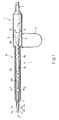
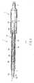
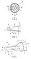
FIG. 1 is a schematic view showing an ultrasonic surgical instrument used for orthopedics according to a first embodiment of the present invention;FIG. 2 is a cross-sectional view showing the ultrasonic surgical instrument taken along line A-A shown inFIG. 1 ;FIG. 3 is a cross-sectional view showing the ultrasonic surgical instrument taken along line B-B shown inFIG. 1 ;FIG. 4 is a cross-sectional view showing the distal end of a shearing member and a procedural unit;FIG. 5 is a perspective view showing the distal end of a shearing member and a procedural unit;FIG. 6A is a view showing a procedural unit according to a modification example;FIG. 6B is a view showing a procedural unit according to another modification example;FIG. 7 is a perspective view showing a procedural unit according to a second embodiment of the present invention;FIG. 8 is a perspective view showing the distal end of a shearing member and a procedural unit;FIG. 9 is a schematic view showing an ultrasonic surgical instrument used for orthopedics according to a third embodiment of the present invention;FIG. 10 is a traverse cross-sectional view showing a procedural unit and a cutting member;FIG. 11 is a longitudinally cross-sectional view showing a procedural unit and a cutting member;FIG. 12 is a perspective view showing a procedural unit;FIG. 13 is a perspective view showing a state that a procedural unit and a cutting member is rotated with respect.to the procedural unit; andFIG. 14 is a view showing a procedural unit according to a modification example.- Various embodiments of the present invention will be hereinafter described with reference to the accompanying drawings.
- A first embodiment will be described below with reference to
FIGS. 1 to 5 . - As shown in
FIG. 1 , an ultrasonic surgical instrument 1 used for orthopedics treats a surgical target portion in an orthopedic operation, for example. The surgical target portion is, for example, hard tissues such as bones and cartilage. The procedure means cut-off and cutting, for example. - The ultrasonic surgical instrument 1 has a
cylindrical case 11 and asheath 20. Specifically, thecylindrical case 11 is attached to a proximal side of the ultrasonic surgical instrument 1. Thesheath 20 is attached to the distal side of thecase 11. - The proximal side of the
case 11 is connected with anoutput connection cable 2. Thecase 11 is connected with a power supply unit (not shown) via theoutput connection cable 2. - As illustrated in
FIGS. 1 and2 , anultrasonic transducer 12 is fixedly provided in thecase 11. Theultrasonic transducer 12 has a piezoelectric element and ahorn 12a. Specifically, the piezoelectric element produces ultrasonic vibration. Thehorn 12a is attached to the distal end of theultrasonic transducer 12 in the longitudinal direction of thecase 11, and amplifies ultrasonic vibration. - The
ultrasonic transducer 12 is a member, which converts electrical energy to ultrasonic vibration. The energy is produced by the power supply unit (not shown), and then, supplied to theultrasonic transducer 12 from the driver via theoutput connection cable 2, and thus, converted to ultrasonic vibration. - For example, the
ultrasonic.transducer 12 is a bolt-clamped langevin type transducer (BLT). - The
horn 12a is made of metallic materials such as titanium, duralumin and stainless. - The distal end of the
horn 12a is attached with aprobe 30, which is inserted in thesheath 20. Theprobe 30 is a transmission member for transmitting ultrasonic vibration amplified by thehorn 12a to the distal side of the ultrasonic surgical instrument 1. Theprobe 30 is removably fastened (fixed) to thehorn 12a using a screw, for example. In other words, theprobe 30 is connected to theultrasonic transducer 12 via thehorn 12a at the proximal end of theprobe 30. Therefore, theprobe 30 transmits ultrasonic vibration produced by theultrasonic transducer 12 from the proximal end of theprobe 30 to the distal end (distal end of the ultrasonic surgical instrument 1) thereof. - The
probe 30 is made of metallic materials such as titanium, duralumin and stainless. - The
probe 30 further has ahorn 30d on the proximal side of theprobe 30. Thehorn 30d further amplifies ultrasonic vibration transmitted from the ultrasonic transducer 12 (horn 12a). - The distal end of the
probe 30 is provided with aprocedural unit 31, which projects from the distal end of thesheath 20. Theprocedural unit 31 treats a surgical target portion using ultrasonic vibration produced by theultrasonic transducer 12 and transmitted from theprobe 30. Theprocedural unit 31 has a flat shape approximately. Theprocedural unit 31 contacts with the surgical target portion, and thereby, treats it using ultrasonic vibration. - The
probe 30 further has a support member (rubber lining) 30e at an intermediate (antinode) position of the ultrasonic vibration. Thesupport member 30e is used for fixing theprobe 30 in thesheath 20. For example, thesupport member 30e is made of a resin such as silicon rubber. - The
procedural unit 31 has a long-diameter loop shape in the longitudinal direction of the case 11 (in the longitudinal direction of the probe 30). Theprocedural unit 31 is formed with anopening 31a, which penetrates in the thickness direction of theprocedural unit 31. The distal end of theopening 31a in the longitudinal direction of theprobe 30 is formed with ashearing edge 31b (seeFIG. 4 ). Theshearing edge 31b is sheared a surgical target portion together with anouter blade 21a described later. Theshearing edge 31b is formed in a desired inclined state to shear a surgical target portion. Theshearing edge 31b is formed in a desired inclined state to the longitudinal direction of theprobe 30 at the distal end of the longitudinal direction of theprobe 30 in the loop. In other words, theshearing edge 31b is formed in a desired state of being inclined from one surface (e.g.,upper surface 31c) of theprocedural unit 31 to the other surface (e.g.,lower surface 31d). Theshearing edge 31b is a procedural unit main body for shearing a surgical target portion together with anouter blade 21a described later, that is, a shearing portion. - The
sheath 20 is provided with agrip 13 for grasping the ultrasonic surgical instrument 1. Thegrip 13 has an elastic force. Thegrip 13 is a control unit, which slides a shearingmember 21 to theprobe 30 including theprocedural unit 31 along the longitudinal direction of theprobe 30. - As described above, the
case 11 is provided with thesheath 20 in which theprobe 30 is inserted, at the distal end of thecase 11. In other words, thesheath 20 covers theprobe 30. - As seen from
FIGS. 1 to 3 , thesheath 20 has aninner tube 20b covering thesupport member 30e, and anouter tube 20c covering theinner tube 20b. - The foregoing inner and
outer tubes - As shown in
FIG. 3 , theouter tube 20c has a cylindrical shape while theinner tube 20b has a non-cylindrical shape. Thus, aspace 20d is formed between the outer andinner tubes space 20d is formed along the longitudinal direction of thesheath 20. Thespace 20d is provided with a shearingmember 21. The proximal end of the shearingmember 21 is connected to thegrip 13 as shown inFIG. 1 . Moreover, the distal end of the shearingmember 21 projects from the distal end of thesheath 20 like theprocedural unit 31 as shown inFIGS. 1 and2 , and has an outermetallic blade 21a. Namely, the shearingmember 21 is provided in thesheath 20 so that it projects from the distal end of thesheath 20, and a shearing member for shearing a surgical target portion. In other words, the shearingmember 21 is a procedural member for shearing the surgical target portion. Theouter blade 21a is a procedural member main body for shearing the surgical target portion together with theshearing edge 31b. - The shearing
member 21 is slidable along the longitudinal direction of theprobe 30 with respect to theprobe 30 includingprocedural unit 31 by operating thegrip 13. The foregoing operation of thegrip 13 means that a doctor (operator) grasps or releases thegrip 13. Namely, the shearingmember 21 has a slidable shape in the sheath 20 (between outer andinner tubes space 20d). In this case, the shearingmember 21 is slidable along the longitudinal direction of thesheath 20 with respect to theprobe 30 includingprocedural unit 31 by operating thegrip 13. Therefore, the shape of the shearingmember 21 has no need of the same as that of thespace 20d. - When the shearing
member 21 slides along the longitudinal direction of thesheath 20 with respect to theprobe 30 includingprocedural unit 31, theouter blade 21a slides on the procedural unit 31 (upper andlower surfaces FIG. 5 . In this way, the shearingmember 21 moves to theshearing edge 31b. At that time, theouter blade 21a overlaps with the shearingedge 31, and thereby, theouter blade 21a and theshearing edge 31b shear a surgical target portion. - The operation according to this embodiment will be described below.
- The
procedural unit 31 contacts with a surgical target portion of a living tissue. In this state, electrical energy produced by the power supply unit (not shown) is supplied from the drive (not shown) to theultrasonic transducer 12 via theoutput connection cable 2. Then, the foregoing energy is converted to ultrasonic vibration by theultrasonic transducer 12. The ultrasonic vibration is amplified by thehorn 12a, and transmitted to theprobe 30. Then the ultrasonic vibration further is amplified by thehorn 30d and then, transmitted from theprobe 30 to the surgical target portion via theprocedural unit 31. Namely, the ultrasonic vibration is transmitted from the proximal end of theprobe 30 to the distal end thereof. In this way, the surgical target portion is treated by means of theprocedural unit 31. - When a doctor (operator) grasps the
grip 13, the shearingmember 21 slides toward the distal end of theprocedural unit 31 along the longitudinal direction of theprobe 30. In this way, theouter blade 21a slides on the procedural unit 31 (upper andlower surfaces shearing edge 31b. In this case, theouter blade 21a overlaps with theshearing edge 31b, and thereby, the surgical target portion is sheared by theouter blade 21a and the ultrasonically vibratingshearing edge 31b. - Conversely, when a doctor releases the
grip 13, thegrip 13 is returned to the previous state that the doctor grasps thegrip 13, by elastic force. In this way, the shearingmember 21 slides toward the distal end of thesheath 20 along the longitudinal direction of theprobe 30. - As described above, according to this embodiment, the surgical target portion is easily treated by the
procedural unit 31 using ultrasonic vibration. In addition, according to this embodiment, thegrip 13 is grasped so that the sharingmember 21 is slidable. In this way, the surgical target portion is treated by theouter blade 21a and the ultrasonically vibratingshearing edge 31b. According to this embodiment, the surgical target portion is easily and delicately treated. Therefore, this serves to treat the surgical target portion without giving damage to soft tissues (without involving soft tissues). As a result, the surgical target portion is treated without giving unexpected damage. - According to this embodiment, the surgical target portion is placed in the
opening 31a, and thereby, a procedure such as cutting is easily performed using ultrasonic vibration. - As seen from the foregoing description, this embodiment can provide two procedures, that is, cutting and shearing using ultrasonic vibration.
- According to this embodiment, a sheared surface of the surgical target portion is made smooth by ultrasonic vibration of the
shearing edge 31b. This serves to relieve pain of a patient after being operated. - According to this embodiment, the shearing
member 21 is slid to treat a surgical target portion. Therefore, a procedure is carried out without involving soft tissues, and without giving unexpected damage (i.e., it is possible to prevent damage of the surgical target portion). - According to this embodiment, the
grip 13 is grasped, and thereby, the surgical target portion is sheared. Therefore, the shearing operation is easy. - It should be noted that the
shearing edge 31b has no need to be limited to the shape shown inFIG. 4 . - For example, the
shearing edge 31b may be formed obliquely from theupper surface 31c of theprocedural unit 31 toward the longitudinal direction of theprobe 30 and from thelower surface 31d thereof toward the same, as seen fromFIG. 6A . - Moreover, as shown in
FIG. 6B , theshearing edge 31b may be formed vertically from theupper surface 31c of theprocedural unit 31 to thelower surface 31d with respect to the longitudinal direction of theprobe 30. - A second embodiment of the present invention will be described below with reference to
FIGS. 7 and 8 . The same numbers are used to designate portions having the same structure as the first embodiment and its modification example, and the explanation is omitted. - A
procedural unit 33 of this second embodiment has noopening 31a. Theprocedural unit 33 is integrally formed with a projectingportion 33, which vertically projects with respect to the longitudinal direction of aprobe 30. In other words, theprocedural unit 33 including the projectingportion 33a has a hook shape. The projectingportion 33a has ashearing edge 33b (procedural unit main body), which is a shearing portion same as theshearing edge 31b, at the chip end of the vertically projectingportion 33a. Further, the projectingportion 33a has a desired height so that theshearing edge 33b overlaps with anouter blade 21a in the vertical direction. - When the
procedural unit 33 treats a surgical target portion, an ultrasonic surgical instrument 1 including theprocedural unit 33 moves in a state that theprocedural unit 33 projects from the distal end of asheath 20. The projectingportion 33a contacts with the surgical target portion, and thereby, theprocedural unit 33 treats the surgical target portion using ultrasonic vibration. - When a doctor (operator) grasps a
grip 13, a shearingmember 21 slides toward the projectingportion 33a along the longitudinal direction of theprobe 30 as shown inFIG. 8 . In this way, anouter blade 21a moves toward theshearing edge 33b. At that time, theouter blade 21a overlaps with theshearing edge 33b, and thereby, the surgical target portion is cut or treated by theouter blade 21a and theshearing edge 33b. - According to the second embodiment, the same effect as the first embodiment is obtained.
- The
procedural unit 33 of this embodiment has a hook shape. Therefore, according to this embodiment, theprocedural unit 33 easily hooks the surgical target portion. This serves to simplify the operation until a procedure is carried out. - A third embodiment of the present invention will be described below with reference to
FIGS. 9 and13 . The same numbers are used to designate portions having the same structure as the first embodiment and its modification example, and the explanation is omitted. - An ultrasonic surgical instrument 1 of this third embodiment has a cutting
member 44. When acontrol unit 40 is rotated, the cuttingmember 44 is rotated with respect to aprocedural unit 42 in accordance with the rotation of thecontrol unit 40. The cuttingmember 44 is rotatable with respect to theprocedural unit 42, and is a procedural member for cutting a surgical target portion. - The
procedural unit 42 has a flat shape, and contacts with a surgical target portion to treat it using ultrasonic vibration. Theprocedural unit 42 has a large-diameter loop shape in the longitudinal direction of a case 11 (of the probe 30). Theprocedural unit 42 is formed with anopening 42a, which penetrates in the thickness direction of theprocedural unit 42. Theopening 42a has acutting edge 42b at the outer peripheral portion. Thecutting edge 42b is a cutting unit for cutting a surgical target portion together with ablade 44a described later. In other words, thecutting edge 42b is formed along the longitudinal direction in the loop. Thecutting edge 42b is a procedural unit main body for cutting a surgical target portion together with ablade 44a described later. - A cutting
member 44 is inserted in theopening 42a. The cuttingmember 44 rotates with respect to theprocedural unit 42. Further, the cuttingmember 44 has ametallic blade 44a, which is formed to be fitted in theopening 42a. Theblade 44a is a procedural member main body. - The cutting
member 44 is rotatable with respect to theprobe 30 including theprocedural unit 42 by operating thecontrol unit 40. The rotation mechanism for rotating the cuttingmember 44 in accordance with the operation of thecontrol unit 40 is omitted for simplification of the drawings. However, it is obvious for the skilled person to include a known rotation mechanism. - When the cutting
member 44 is rotated, theblade 44a moves toward thecutting edge 42b. At that time, theblade 44a overlaps with thecutting edge 42b so that a surgical target portion is held between theblade 44a and thecutting edge 42b. In this way, theblade 44a and thecutting edge 42b cut the surgical target portion. - The operation of this third embodiment will be described below.
- When a doctor (operator) grasps the
control unit 40, the cuttingmember 44 is rotated toward theopening 42a. In this way, theblade 44a moves toward thecutting edge 42b. - In this case, living tissues, that is, a surgical target portion is held between the
procedural unit 42 and the cuttingmember 44. The cuttingmember 44 further rotates toward theopening 42a from the foregoing state. Electrical energy produced by the power supply unit is converted to ultrasonic vibration as in the first embodiment. The ultrasonic vibration is amplified as in the first embodiment, and then, transmitted to theprobe 30. In this case, the ultrasonic vibration is transmitted to a surgical target portion via theprocedural unit 42. - Then, the
blade 44a overlaps with thecutting edge 42b so that a surgical target portion is held between theblade 44a and thecutting edge 42b. In this way, theblade 44a and thecutting edge 42b cut the surgical target portion. - According to this embodiment, the same effect as the first embodiment is obtained.
- According to this embodiment, the cutting
member 44 is rotated toward theopening 42a so that a surgical target portion is held between theblade 44a and thecutting edge 42b. Therefore, this serves to cut the surgical target portion only. In addition, according to this embodiment, the surgical target portion is treated in a state of being held between there. Therefore, a surgical target portion having some thickness is easily cut. - The
procedural unit 42 of this embodiment is not limited to the foregoing shape. For example, as seen fromFIG. 14 , theprocedural unit 42 has a U-letter shape when being viewed from the vertical direction in the longitudinal direction of theprobe 30. Theprocedural unit 42 has afirst cutting edge 46a, which is one of the facing U-letter sides, and asecond cutting edge 46b, which is the other thereof. The foregoing first andsecond cutting edges second cutting edges second cutting edges probe 30. The cuttingmember 44 rotating to theprocedural unit 42 is inserted in aspace 48 formed between the first andsecond cutting edges - The present invention is not limited to the foregoing embodiments. In the inventive stage, constituent elements may be modified and embodied without departing from the subject matter. A plurality of constituent elements disclosed in the foregoing embodiments are properly combined, and thereby, various inventions can be provided.
Claims (8)
- An ultrasonic surgical instrument (1)characterized by comprising:an ultrasonic transducer (12) producing ultrasonic vibration;a transmission member (30) connected to the ultrasonic transducer (12) at a proximal end, and transmitting ultrasonic vibration produced by the ultrasonic transducer (12) from the proximal end to the distal end;a sheath (20) in which the transmission member (30) is inserted;a procedural unit (31, 33, 42) provided to the distal end of the transmission member (30) so that it projects from the distal end of the sheath (20), and treating a surgical target portion using ultrasonic vibration transmitted from the transmission member (30);a procedural unit main body (31b, 33b, 42b) provided in the procedural unit (31, 33, 42), and treating the surgical target portion;a procedural member (21, 44) provided in the sheath (20) so that it projects from the distal end of the sheath (20) to treat the surgical target portion; anda procedural member main body (21a, 44a) provided at the distal end of the procedural member (21, 44) to treat the surgical target portion,the procedural member main body (21a, 44a) overlapping with the procedural unit main body (31b, 33b, 42b), and thereby, the procedural member main body (21a, 44a) and the procedural unit main body (31b, 33b, 42b) treating the surgical target portion.
- The instrument (1) according to claim 1,characterized in that the procedural member (21) is a shearing member, which slides along the longitudinal direction of the transmission member (30) with respect to the transmission member (30), and the procedural unit main body (31b, 33b) is a shearing portion, and further, the procedural member main body (21a) and the procedural unit main body (31b, 33b) shear the surgical target portion.
- The instrument (1) according to claim 2,characterized in that the procedural unit (31) has a large-diameter loop shape in the longitudinal direction of the transmission member (30), and the procedural unit main body (31b) is formed in a state of being desired inclined to the longitudinal direction of the transmission member (30) at the distal end of the longitudinal direction of the transmission member (30) in a loop.
- The instrument (1) according to claim 2,characterized in that the procedural unit (31) has a large-diameter loop shape in the longitudinal direction of the transmission member (30), and the procedural unit main body (31b) is formed vertically to the longitudinal direction of the transmission member (30) at the distal end of the longitudinal direction of the transmission member (30) in a loop.
- The instrument (1) according to claim 2,characterized in that the procedural unit (33) has a projecting portion (33a) formed vertically to projects with respect to the longitudinal direction of the transmission member (30), and the projecting portion (33a) has the procedural unit main body (33b) at the distal end of the projecting portion (33a) in the vertical direction.
- The instrument (1) according to claim 1,characterized in that the procedural member (44) is rotatable with respect to the procedural unit (42).
- The instrument (1) according to claim 6,characterized in that the procedural unit (42) has a large-diameter loop shape in the longitudinal direction of the transmission member (30), and the procedural unit main body (42b) is a cutting unit formed along the longitudinal direction of the transmission member (30) in a loop,
the procedural member (44) is a cutting member,
the procedural member (44) is rotated toward the procedural unit (42) so that the procedural member main body (44a) and the procedural unit main body (42b) overlaps, and the surgical target portion is held between the procedural member main body (44a) and the procedural unit main body (42b), and thereby, the procedural member main body (44a) and the procedural unit main body (42b) cut the surgical target portion. - The instrument (1) according to claim 6,characterized in that the procedural unit (42) has a U-letter shape when being viewed from the vertical direction in the longitudinal direction of the transmission member (30), and
the procedural unit main bodies (46a, 46b) are provided as one side of the facing U-letter shape and the other side thereof, respectively.
Applications Claiming Priority (1)
| Application Number | Priority Date | Filing Date | Title |
|---|---|---|---|
| US7389908P | 2008-06-19 | 2008-06-19 |
Publications (3)
| Publication Number | Publication Date |
|---|---|
| EP2135570A2true EP2135570A2 (en) | 2009-12-23 |
| EP2135570A3 EP2135570A3 (en) | 2009-12-30 |
| EP2135570B1 EP2135570B1 (en) | 2016-12-07 |
Family
ID=41278339
Family Applications (1)
| Application Number | Title | Priority Date | Filing Date |
|---|---|---|---|
| EP09005173.1ANot-in-forceEP2135570B1 (en) | 2008-06-19 | 2009-04-08 | Ultrasonic surgical instruments |
Country Status (3)
| Country | Link |
|---|---|
| US (1) | US8236018B2 (en) |
| EP (1) | EP2135570B1 (en) |
| JP (1) | JP5379501B2 (en) |
Families Citing this family (152)
| Publication number | Priority date | Publication date | Assignee | Title |
|---|---|---|---|---|
| US11229472B2 (en) | 2001-06-12 | 2022-01-25 | Cilag Gmbh International | Modular battery powered handheld surgical instrument with multiple magnetic position sensors |
| US8182501B2 (en) | 2004-02-27 | 2012-05-22 | Ethicon Endo-Surgery, Inc. | Ultrasonic surgical shears and method for sealing a blood vessel using same |
| US20060079879A1 (en) | 2004-10-08 | 2006-04-13 | Faller Craig N | Actuation mechanism for use with an ultrasonic surgical instrument |
| US20070191713A1 (en) | 2005-10-14 | 2007-08-16 | Eichmann Stephen E | Ultrasonic device for cutting and coagulating |
| US7621930B2 (en) | 2006-01-20 | 2009-11-24 | Ethicon Endo-Surgery, Inc. | Ultrasound medical instrument having a medical ultrasonic blade |
| EP1835699A1 (en)* | 2006-03-17 | 2007-09-19 | ABB PATENT GmbH | Robot controller |
| US8911460B2 (en) | 2007-03-22 | 2014-12-16 | Ethicon Endo-Surgery, Inc. | Ultrasonic surgical instruments |
| US8142461B2 (en) | 2007-03-22 | 2012-03-27 | Ethicon Endo-Surgery, Inc. | Surgical instruments |
| US20080234709A1 (en) | 2007-03-22 | 2008-09-25 | Houser Kevin L | Ultrasonic surgical instrument and cartilage and bone shaping blades therefor |
| US8057498B2 (en) | 2007-11-30 | 2011-11-15 | Ethicon Endo-Surgery, Inc. | Ultrasonic surgical instrument blades |
| US8226675B2 (en) | 2007-03-22 | 2012-07-24 | Ethicon Endo-Surgery, Inc. | Surgical instruments |
| US8348967B2 (en) | 2007-07-27 | 2013-01-08 | Ethicon Endo-Surgery, Inc. | Ultrasonic surgical instruments |
| US8808319B2 (en) | 2007-07-27 | 2014-08-19 | Ethicon Endo-Surgery, Inc. | Surgical instruments |
| US8523889B2 (en) | 2007-07-27 | 2013-09-03 | Ethicon Endo-Surgery, Inc. | Ultrasonic end effectors with increased active length |
| US8882791B2 (en) | 2007-07-27 | 2014-11-11 | Ethicon Endo-Surgery, Inc. | Ultrasonic surgical instruments |
| US8430898B2 (en) | 2007-07-31 | 2013-04-30 | Ethicon Endo-Surgery, Inc. | Ultrasonic surgical instruments |
| US9044261B2 (en) | 2007-07-31 | 2015-06-02 | Ethicon Endo-Surgery, Inc. | Temperature controlled ultrasonic surgical instruments |
| US8252012B2 (en) | 2007-07-31 | 2012-08-28 | Ethicon Endo-Surgery, Inc. | Ultrasonic surgical instrument with modulator |
| US8512365B2 (en) | 2007-07-31 | 2013-08-20 | Ethicon Endo-Surgery, Inc. | Surgical instruments |
| EP2217157A2 (en) | 2007-10-05 | 2010-08-18 | Ethicon Endo-Surgery, Inc. | Ergonomic surgical instruments |
| US10010339B2 (en) | 2007-11-30 | 2018-07-03 | Ethicon Llc | Ultrasonic surgical blades |
| US8058771B2 (en) | 2008-08-06 | 2011-11-15 | Ethicon Endo-Surgery, Inc. | Ultrasonic device for cutting and coagulating with stepped output |
| US9089360B2 (en) | 2008-08-06 | 2015-07-28 | Ethicon Endo-Surgery, Inc. | Devices and techniques for cutting and coagulating tissue |
| US9700339B2 (en) | 2009-05-20 | 2017-07-11 | Ethicon Endo-Surgery, Inc. | Coupling arrangements and methods for attaching tools to ultrasonic surgical instruments |
| US8650728B2 (en) | 2009-06-24 | 2014-02-18 | Ethicon Endo-Surgery, Inc. | Method of assembling a transducer for a surgical instrument |
| US9017326B2 (en) | 2009-07-15 | 2015-04-28 | Ethicon Endo-Surgery, Inc. | Impedance monitoring apparatus, system, and method for ultrasonic surgical instruments |
| US8461744B2 (en) | 2009-07-15 | 2013-06-11 | Ethicon Endo-Surgery, Inc. | Rotating transducer mount for ultrasonic surgical instruments |
| US8663220B2 (en) | 2009-07-15 | 2014-03-04 | Ethicon Endo-Surgery, Inc. | Ultrasonic surgical instruments |
| US11090104B2 (en) | 2009-10-09 | 2021-08-17 | Cilag Gmbh International | Surgical generator for ultrasonic and electrosurgical devices |
| US10441345B2 (en) | 2009-10-09 | 2019-10-15 | Ethicon Llc | Surgical generator for ultrasonic and electrosurgical devices |
| US9050093B2 (en) | 2009-10-09 | 2015-06-09 | Ethicon Endo-Surgery, Inc. | Surgical generator for ultrasonic and electrosurgical devices |
| USRE47996E1 (en) | 2009-10-09 | 2020-05-19 | Ethicon Llc | Surgical generator for ultrasonic and electrosurgical devices |
| US9168054B2 (en) | 2009-10-09 | 2015-10-27 | Ethicon Endo-Surgery, Inc. | Surgical generator for ultrasonic and electrosurgical devices |
| US8951272B2 (en) | 2010-02-11 | 2015-02-10 | Ethicon Endo-Surgery, Inc. | Seal arrangements for ultrasonically powered surgical instruments |
| US8579928B2 (en) | 2010-02-11 | 2013-11-12 | Ethicon Endo-Surgery, Inc. | Outer sheath and blade arrangements for ultrasonic surgical instruments |
| US8469981B2 (en) | 2010-02-11 | 2013-06-25 | Ethicon Endo-Surgery, Inc. | Rotatable cutting implement arrangements for ultrasonic surgical instruments |
| US8531064B2 (en) | 2010-02-11 | 2013-09-10 | Ethicon Endo-Surgery, Inc. | Ultrasonically powered surgical instruments with rotating cutting implement |
| US8382782B2 (en) | 2010-02-11 | 2013-02-26 | Ethicon Endo-Surgery, Inc. | Ultrasonic surgical instruments with partially rotating blade and fixed pad arrangement |
| US8323302B2 (en)* | 2010-02-11 | 2012-12-04 | Ethicon Endo-Surgery, Inc. | Methods of using ultrasonically powered surgical instruments with rotatable cutting implements |
| US9259234B2 (en) | 2010-02-11 | 2016-02-16 | Ethicon Endo-Surgery, Llc | Ultrasonic surgical instruments with rotatable blade and hollow sheath arrangements |
| US8486096B2 (en)* | 2010-02-11 | 2013-07-16 | Ethicon Endo-Surgery, Inc. | Dual purpose surgical instrument for cutting and coagulating tissue |
| US8419759B2 (en)* | 2010-02-11 | 2013-04-16 | Ethicon Endo-Surgery, Inc. | Ultrasonic surgical instrument with comb-like tissue trimming device |
| US8961547B2 (en) | 2010-02-11 | 2015-02-24 | Ethicon Endo-Surgery, Inc. | Ultrasonic surgical instruments with moving cutting implement |
| US8409235B2 (en)* | 2010-04-30 | 2013-04-02 | Medtronic Xomed, Inc. | Rotary cutting tool with improved cutting and reduced clogging on soft tissue and thin bone |
| GB2480498A (en) | 2010-05-21 | 2011-11-23 | Ethicon Endo Surgery Inc | Medical device comprising RF circuitry |
| US8795327B2 (en) | 2010-07-22 | 2014-08-05 | Ethicon Endo-Surgery, Inc. | Electrosurgical instrument with separate closure and cutting members |
| US9192431B2 (en) | 2010-07-23 | 2015-11-24 | Ethicon Endo-Surgery, Inc. | Electrosurgical cutting and sealing instrument |
| US9259265B2 (en) | 2011-07-22 | 2016-02-16 | Ethicon Endo-Surgery, Llc | Surgical instruments for tensioning tissue |
| WO2013119545A1 (en) | 2012-02-10 | 2013-08-15 | Ethicon-Endo Surgery, Inc. | Robotically controlled surgical instrument |
| US9226766B2 (en) | 2012-04-09 | 2016-01-05 | Ethicon Endo-Surgery, Inc. | Serial communication protocol for medical device |
| US9241731B2 (en) | 2012-04-09 | 2016-01-26 | Ethicon Endo-Surgery, Inc. | Rotatable electrical connection for ultrasonic surgical instruments |
| US9724118B2 (en) | 2012-04-09 | 2017-08-08 | Ethicon Endo-Surgery, Llc | Techniques for cutting and coagulating tissue for ultrasonic surgical instruments |
| US9237921B2 (en) | 2012-04-09 | 2016-01-19 | Ethicon Endo-Surgery, Inc. | Devices and techniques for cutting and coagulating tissue |
| US9439668B2 (en) | 2012-04-09 | 2016-09-13 | Ethicon Endo-Surgery, Llc | Switch arrangements for ultrasonic surgical instruments |
| US20140005705A1 (en) | 2012-06-29 | 2014-01-02 | Ethicon Endo-Surgery, Inc. | Surgical instruments with articulating shafts |
| US9226767B2 (en) | 2012-06-29 | 2016-01-05 | Ethicon Endo-Surgery, Inc. | Closed feedback control for electrosurgical device |
| US9198714B2 (en) | 2012-06-29 | 2015-12-01 | Ethicon Endo-Surgery, Inc. | Haptic feedback devices for surgical robot |
| US20140005702A1 (en) | 2012-06-29 | 2014-01-02 | Ethicon Endo-Surgery, Inc. | Ultrasonic surgical instruments with distally positioned transducers |
| US9351754B2 (en) | 2012-06-29 | 2016-05-31 | Ethicon Endo-Surgery, Llc | Ultrasonic surgical instruments with distally positioned jaw assemblies |
| US9408622B2 (en) | 2012-06-29 | 2016-08-09 | Ethicon Endo-Surgery, Llc | Surgical instruments with articulating shafts |
| US9283045B2 (en) | 2012-06-29 | 2016-03-15 | Ethicon Endo-Surgery, Llc | Surgical instruments with fluid management system |
| US9820768B2 (en) | 2012-06-29 | 2017-11-21 | Ethicon Llc | Ultrasonic surgical instruments with control mechanisms |
| US9326788B2 (en) | 2012-06-29 | 2016-05-03 | Ethicon Endo-Surgery, Llc | Lockout mechanism for use with robotic electrosurgical device |
| US9393037B2 (en) | 2012-06-29 | 2016-07-19 | Ethicon Endo-Surgery, Llc | Surgical instruments with articulating shafts |
| EP2900158B1 (en) | 2012-09-28 | 2020-04-15 | Ethicon LLC | Multi-function bi-polar forceps |
| US10201365B2 (en) | 2012-10-22 | 2019-02-12 | Ethicon Llc | Surgeon feedback sensing and display methods |
| US9095367B2 (en) | 2012-10-22 | 2015-08-04 | Ethicon Endo-Surgery, Inc. | Flexible harmonic waveguides/blades for surgical instruments |
| US20140135804A1 (en) | 2012-11-15 | 2014-05-15 | Ethicon Endo-Surgery, Inc. | Ultrasonic and electrosurgical devices |
| US10226273B2 (en) | 2013-03-14 | 2019-03-12 | Ethicon Llc | Mechanical fasteners for use with surgical energy devices |
| US9241728B2 (en) | 2013-03-15 | 2016-01-26 | Ethicon Endo-Surgery, Inc. | Surgical instrument with multiple clamping mechanisms |
| US9814514B2 (en) | 2013-09-13 | 2017-11-14 | Ethicon Llc | Electrosurgical (RF) medical instruments for cutting and coagulating tissue |
| US9265926B2 (en) | 2013-11-08 | 2016-02-23 | Ethicon Endo-Surgery, Llc | Electrosurgical devices |
| GB2521228A (en) | 2013-12-16 | 2015-06-17 | Ethicon Endo Surgery Inc | Medical device |
| GB2521229A (en) | 2013-12-16 | 2015-06-17 | Ethicon Endo Surgery Inc | Medical device |
| US9795436B2 (en) | 2014-01-07 | 2017-10-24 | Ethicon Llc | Harvesting energy from a surgical generator |
| US9554854B2 (en) | 2014-03-18 | 2017-01-31 | Ethicon Endo-Surgery, Llc | Detecting short circuits in electrosurgical medical devices |
| US10092310B2 (en) | 2014-03-27 | 2018-10-09 | Ethicon Llc | Electrosurgical devices |
| US10463421B2 (en) | 2014-03-27 | 2019-11-05 | Ethicon Llc | Two stage trigger, clamp and cut bipolar vessel sealer |
| US9737355B2 (en) | 2014-03-31 | 2017-08-22 | Ethicon Llc | Controlling impedance rise in electrosurgical medical devices |
| US9913680B2 (en) | 2014-04-15 | 2018-03-13 | Ethicon Llc | Software algorithms for electrosurgical instruments |
| US10285724B2 (en) | 2014-07-31 | 2019-05-14 | Ethicon Llc | Actuation mechanisms and load adjustment assemblies for surgical instruments |
| US10639092B2 (en) | 2014-12-08 | 2020-05-05 | Ethicon Llc | Electrode configurations for surgical instruments |
| US10245095B2 (en) | 2015-02-06 | 2019-04-02 | Ethicon Llc | Electrosurgical instrument with rotation and articulation mechanisms |
| US10342602B2 (en) | 2015-03-17 | 2019-07-09 | Ethicon Llc | Managing tissue treatment |
| US10321950B2 (en) | 2015-03-17 | 2019-06-18 | Ethicon Llc | Managing tissue treatment |
| US10595929B2 (en) | 2015-03-24 | 2020-03-24 | Ethicon Llc | Surgical instruments with firing system overload protection mechanisms |
| US10034684B2 (en) | 2015-06-15 | 2018-07-31 | Ethicon Llc | Apparatus and method for dissecting and coagulating tissue |
| US11020140B2 (en) | 2015-06-17 | 2021-06-01 | Cilag Gmbh International | Ultrasonic surgical blade for use with ultrasonic surgical instruments |
| US11141213B2 (en) | 2015-06-30 | 2021-10-12 | Cilag Gmbh International | Surgical instrument with user adaptable techniques |
| US10357303B2 (en) | 2015-06-30 | 2019-07-23 | Ethicon Llc | Translatable outer tube for sealing using shielded lap chole dissector |
| US10898256B2 (en) | 2015-06-30 | 2021-01-26 | Ethicon Llc | Surgical system with user adaptable techniques based on tissue impedance |
| US11129669B2 (en) | 2015-06-30 | 2021-09-28 | Cilag Gmbh International | Surgical system with user adaptable techniques based on tissue type |
| US11051873B2 (en) | 2015-06-30 | 2021-07-06 | Cilag Gmbh International | Surgical system with user adaptable techniques employing multiple energy modalities based on tissue parameters |
| US10034704B2 (en) | 2015-06-30 | 2018-07-31 | Ethicon Llc | Surgical instrument with user adaptable algorithms |
| US10154852B2 (en) | 2015-07-01 | 2018-12-18 | Ethicon Llc | Ultrasonic surgical blade with improved cutting and coagulation features |
| JP6033503B1 (en)* | 2015-07-23 | 2016-11-30 | オリンパス株式会社 | Ultrasonic treatment device and ultrasonic treatment assembly |
| WO2017027745A1 (en) | 2015-08-11 | 2017-02-16 | Reach Surgical, Inc. | Double hook ultrasonic surgical blade |
| US10194973B2 (en) | 2015-09-30 | 2019-02-05 | Ethicon Llc | Generator for digitally generating electrical signal waveforms for electrosurgical and ultrasonic surgical instruments |
| US10595930B2 (en) | 2015-10-16 | 2020-03-24 | Ethicon Llc | Electrode wiping surgical device |
| US10179022B2 (en) | 2015-12-30 | 2019-01-15 | Ethicon Llc | Jaw position impedance limiter for electrosurgical instrument |
| US10575892B2 (en) | 2015-12-31 | 2020-03-03 | Ethicon Llc | Adapter for electrical surgical instruments |
| US11129670B2 (en) | 2016-01-15 | 2021-09-28 | Cilag Gmbh International | Modular battery powered handheld surgical instrument with selective application of energy based on button displacement, intensity, or local tissue characterization |
| US11229471B2 (en) | 2016-01-15 | 2022-01-25 | Cilag Gmbh International | Modular battery powered handheld surgical instrument with selective application of energy based on tissue characterization |
| US11051840B2 (en) | 2016-01-15 | 2021-07-06 | Ethicon Llc | Modular battery powered handheld surgical instrument with reusable asymmetric handle housing |
| US10716615B2 (en) | 2016-01-15 | 2020-07-21 | Ethicon Llc | Modular battery powered handheld surgical instrument with curved end effectors having asymmetric engagement between jaw and blade |
| US12193698B2 (en) | 2016-01-15 | 2025-01-14 | Cilag Gmbh International | Method for self-diagnosing operation of a control switch in a surgical instrument system |
| US10555769B2 (en) | 2016-02-22 | 2020-02-11 | Ethicon Llc | Flexible circuits for electrosurgical instrument |
| US10702329B2 (en) | 2016-04-29 | 2020-07-07 | Ethicon Llc | Jaw structure with distal post for electrosurgical instruments |
| US10646269B2 (en) | 2016-04-29 | 2020-05-12 | Ethicon Llc | Non-linear jaw gap for electrosurgical instruments |
| US10485607B2 (en) | 2016-04-29 | 2019-11-26 | Ethicon Llc | Jaw structure with distal closure for electrosurgical instruments |
| US10456193B2 (en) | 2016-05-03 | 2019-10-29 | Ethicon Llc | Medical device with a bilateral jaw configuration for nerve stimulation |
| US10245064B2 (en) | 2016-07-12 | 2019-04-02 | Ethicon Llc | Ultrasonic surgical instrument with piezoelectric central lumen transducer |
| US10893883B2 (en) | 2016-07-13 | 2021-01-19 | Ethicon Llc | Ultrasonic assembly for use with ultrasonic surgical instruments |
| US10842522B2 (en) | 2016-07-15 | 2020-11-24 | Ethicon Llc | Ultrasonic surgical instruments having offset blades |
| US10376305B2 (en) | 2016-08-05 | 2019-08-13 | Ethicon Llc | Methods and systems for advanced harmonic energy |
| US10285723B2 (en) | 2016-08-09 | 2019-05-14 | Ethicon Llc | Ultrasonic surgical blade with improved heel portion |
| USD847990S1 (en) | 2016-08-16 | 2019-05-07 | Ethicon Llc | Surgical instrument |
| US10736649B2 (en) | 2016-08-25 | 2020-08-11 | Ethicon Llc | Electrical and thermal connections for ultrasonic transducer |
| US10952759B2 (en) | 2016-08-25 | 2021-03-23 | Ethicon Llc | Tissue loading of a surgical instrument |
| CN109792580B (en)* | 2016-09-30 | 2020-11-10 | 奥林巴斯株式会社 | Ultrasonic transducer and method for manufacturing ultrasonic transducer |
| WO2018078828A1 (en) | 2016-10-28 | 2018-05-03 | オリンパス株式会社 | Ultrasonic probe |
| WO2018078825A1 (en)* | 2016-10-28 | 2018-05-03 | オリンパス株式会社 | Ultrasonic probe |
| US10603064B2 (en) | 2016-11-28 | 2020-03-31 | Ethicon Llc | Ultrasonic transducer |
| US11266430B2 (en) | 2016-11-29 | 2022-03-08 | Cilag Gmbh International | End effector control and calibration |
| US10820920B2 (en) | 2017-07-05 | 2020-11-03 | Ethicon Llc | Reusable ultrasonic medical devices and methods of their use |
| US11786259B1 (en) | 2019-05-28 | 2023-10-17 | Mirus Llc | Systems and methods for ultrasonically-assisted placement of orthopedic implants |
| US11911063B2 (en) | 2019-12-30 | 2024-02-27 | Cilag Gmbh International | Techniques for detecting ultrasonic blade to electrode contact and reducing power to ultrasonic blade |
| US11812957B2 (en) | 2019-12-30 | 2023-11-14 | Cilag Gmbh International | Surgical instrument comprising a signal interference resolution system |
| US11779329B2 (en) | 2019-12-30 | 2023-10-10 | Cilag Gmbh International | Surgical instrument comprising a flex circuit including a sensor system |
| US12076006B2 (en) | 2019-12-30 | 2024-09-03 | Cilag Gmbh International | Surgical instrument comprising an orientation detection system |
| US20210196357A1 (en) | 2019-12-30 | 2021-07-01 | Ethicon Llc | Electrosurgical instrument with asynchronous energizing electrodes |
| US11696776B2 (en) | 2019-12-30 | 2023-07-11 | Cilag Gmbh International | Articulatable surgical instrument |
| US11452525B2 (en) | 2019-12-30 | 2022-09-27 | Cilag Gmbh International | Surgical instrument comprising an adjustment system |
| US12343063B2 (en) | 2019-12-30 | 2025-07-01 | Cilag Gmbh International | Multi-layer clamp arm pad for enhanced versatility and performance of a surgical device |
| US12064109B2 (en) | 2019-12-30 | 2024-08-20 | Cilag Gmbh International | Surgical instrument comprising a feedback control circuit |
| US12023086B2 (en) | 2019-12-30 | 2024-07-02 | Cilag Gmbh International | Electrosurgical instrument for delivering blended energy modalities to tissue |
| US11786294B2 (en) | 2019-12-30 | 2023-10-17 | Cilag Gmbh International | Control program for modular combination energy device |
| US12114912B2 (en) | 2019-12-30 | 2024-10-15 | Cilag Gmbh International | Non-biased deflectable electrode to minimize contact between ultrasonic blade and electrode |
| US11937866B2 (en) | 2019-12-30 | 2024-03-26 | Cilag Gmbh International | Method for an electrosurgical procedure |
| US11786291B2 (en) | 2019-12-30 | 2023-10-17 | Cilag Gmbh International | Deflectable support of RF energy electrode with respect to opposing ultrasonic blade |
| US11986201B2 (en) | 2019-12-30 | 2024-05-21 | Cilag Gmbh International | Method for operating a surgical instrument |
| US11937863B2 (en) | 2019-12-30 | 2024-03-26 | Cilag Gmbh International | Deflectable electrode with variable compression bias along the length of the deflectable electrode |
| US12053224B2 (en) | 2019-12-30 | 2024-08-06 | Cilag Gmbh International | Variation in electrode parameters and deflectable electrode to modify energy density and tissue interaction |
| US12336747B2 (en) | 2019-12-30 | 2025-06-24 | Cilag Gmbh International | Method of operating a combination ultrasonic / bipolar RF surgical device with a combination energy modality end-effector |
| US11684412B2 (en) | 2019-12-30 | 2023-06-27 | Cilag Gmbh International | Surgical instrument with rotatable and articulatable surgical end effector |
| US12262937B2 (en) | 2019-12-30 | 2025-04-01 | Cilag Gmbh International | User interface for surgical instrument with combination energy modality end-effector |
| US20210196362A1 (en) | 2019-12-30 | 2021-07-01 | Ethicon Llc | Electrosurgical end effectors with thermally insulative and thermally conductive portions |
| US11950797B2 (en) | 2019-12-30 | 2024-04-09 | Cilag Gmbh International | Deflectable electrode with higher distal bias relative to proximal bias |
| US11779387B2 (en) | 2019-12-30 | 2023-10-10 | Cilag Gmbh International | Clamp arm jaw to minimize tissue sticking and improve tissue control |
| US12082808B2 (en) | 2019-12-30 | 2024-09-10 | Cilag Gmbh International | Surgical instrument comprising a control system responsive to software configurations |
| US11660089B2 (en) | 2019-12-30 | 2023-05-30 | Cilag Gmbh International | Surgical instrument comprising a sensing system |
| US11944366B2 (en) | 2019-12-30 | 2024-04-02 | Cilag Gmbh International | Asymmetric segmented ultrasonic support pad for cooperative engagement with a movable RF electrode |
Citations (1)
| Publication number | Priority date | Publication date | Assignee | Title |
|---|---|---|---|---|
| US6497715B2 (en) | 2000-11-07 | 2002-12-24 | Miwatec Incorporated | Ultrasonic hand piece and ultrasonic horn for use with the same |
Family Cites Families (14)
| Publication number | Priority date | Publication date | Assignee | Title |
|---|---|---|---|---|
| JPH05220157A (en)* | 1992-02-18 | 1993-08-31 | Olympus Optical Co Ltd | Excision device for medical treatment |
| JP3709226B2 (en)* | 1995-11-10 | 2005-10-26 | オリンパス株式会社 | Ultrasonic coagulation and incision device |
| US6056735A (en)* | 1996-04-04 | 2000-05-02 | Olympus Optical Co., Ltd. | Ultrasound treatment system |
| US5906628A (en)* | 1996-06-26 | 1999-05-25 | Olympus Optical Co., Ltd. | Ultrasonic treatment instrument |
| JPH105237A (en)* | 1996-06-26 | 1998-01-13 | Olympus Optical Co Ltd | Ultrasonic processor |
| AU4603697A (en) | 1996-10-04 | 1998-04-24 | United States Surgical Corporation | Ultrasonic dissection and coagulation system |
| US6231578B1 (en)* | 1998-08-05 | 2001-05-15 | United States Surgical Corporation | Ultrasonic snare for excising tissue |
| US6117152A (en)* | 1999-06-18 | 2000-09-12 | Ethicon Endo-Surgery, Inc. | Multi-function ultrasonic surgical instrument |
| JP4460785B2 (en)* | 2001-02-02 | 2010-05-12 | オリンパス株式会社 | Ultrasonic treatment device |
| JP2003116863A (en)* | 2001-10-10 | 2003-04-22 | Olympus Optical Co Ltd | Ultrasonic treating apparatus |
| US7229455B2 (en)* | 2001-09-03 | 2007-06-12 | Olympus Corporation | Ultrasonic calculus treatment apparatus |
| US20030204199A1 (en)* | 2002-04-30 | 2003-10-30 | Novak Theodore A. D. | Device and method for ultrasonic tissue excision with tissue selectivity |
| US20030212422A1 (en)* | 2002-05-13 | 2003-11-13 | Paul Fenton | Ultrasonic soft tissue cutting and coagulation systems with movable vibrating probe and fixed receiving clamp |
| US7645278B2 (en)* | 2006-02-22 | 2010-01-12 | Olympus Corporation | Coagulating cutter |
- 2009
- 2009-01-29JPJP2009018560Apatent/JP5379501B2/ennot_activeExpired - Fee Related
- 2009-04-06USUS12/418,667patent/US8236018B2/ennot_activeExpired - Fee Related
- 2009-04-08EPEP09005173.1Apatent/EP2135570B1/ennot_activeNot-in-force
Patent Citations (1)
| Publication number | Priority date | Publication date | Assignee | Title |
|---|---|---|---|---|
| US6497715B2 (en) | 2000-11-07 | 2002-12-24 | Miwatec Incorporated | Ultrasonic hand piece and ultrasonic horn for use with the same |
Also Published As
| Publication number | Publication date |
|---|---|
| JP2010000335A (en) | 2010-01-07 |
| JP5379501B2 (en) | 2013-12-25 |
| US8236018B2 (en) | 2012-08-07 |
| EP2135570A3 (en) | 2009-12-30 |
| US20090318945A1 (en) | 2009-12-24 |
| EP2135570B1 (en) | 2016-12-07 |
Similar Documents
| Publication | Publication Date | Title |
|---|---|---|
| EP2135570B1 (en) | Ultrasonic surgical instruments | |
| US10835768B2 (en) | Dual purpose surgical instrument for cutting and coagulating tissue | |
| JP6618913B2 (en) | Ultrasonic bone cutting instrument | |
| EP2533709B1 (en) | Ultrasonic surgical instruments with partially rotating blade and fixed pad arrangement | |
| JP5703360B2 (en) | Ultrasonic surgical device | |
| JP6373861B2 (en) | Ultrasonic surgical blade | |
| JP6615861B2 (en) | Ultrasonic blade overmold | |
| JP7003063B2 (en) | Ultrasonic surgical instrument with cooling duct | |
| JP2005040222A (en) | Ultrasonic treatment apparatus | |
| WO2012149361A1 (en) | Ultrasonic device for cutting and coagulating | |
| JP6816114B2 (en) | Ultrasonic surgical instrument clamp arm with snap-on clamp pad | |
| EP3086723A1 (en) | Loading features for ultrasonic surgical instrument | |
| JP2004194731A (en) | Ultrasonic trocar system | |
| EP3829465B1 (en) | Surgical cutting tool | |
| EP3406214A1 (en) | Medical apparatus, medical apparatus system |
Legal Events
| Date | Code | Title | Description |
|---|---|---|---|
| PUAI | Public reference made under article 153(3) epc to a published international application that has entered the european phase | Free format text:ORIGINAL CODE: 0009012 | |
| PUAL | Search report despatched | Free format text:ORIGINAL CODE: 0009013 | |
| AK | Designated contracting states | Kind code of ref document:A2 Designated state(s):AT BE BG CH CY CZ DE DK EE ES FI FR GB GR HR HU IE IS IT LI LT LU LV MC MK MT NL NO PL PT RO SE SI SK TR | |
| AK | Designated contracting states | Kind code of ref document:A3 Designated state(s):AT BE BG CH CY CZ DE DK EE ES FI FR GB GR HR HU IE IS IT LI LT LU LV MC MK MT NL NO PL PT RO SE SI SK TR | |
| 17P | Request for examination filed | Effective date:20100302 | |
| 17Q | First examination report despatched | Effective date:20100330 | |
| RAP1 | Party data changed (applicant data changed or rights of an application transferred) | Owner name:OLYMPUS CORPORATION | |
| GRAP | Despatch of communication of intention to grant a patent | Free format text:ORIGINAL CODE: EPIDOSNIGR1 | |
| RIC1 | Information provided on ipc code assigned before grant | Ipc:A61B 17/3205 20060101ALN20160602BHEP Ipc:A61B 17/32 20060101AFI20160602BHEP Ipc:A61B 17/3207 20060101ALN20160602BHEP | |
| INTG | Intention to grant announced | Effective date:20160701 | |
| RAP1 | Party data changed (applicant data changed or rights of an application transferred) | Owner name:OLYMPUS CORPORATION | |
| RAP1 | Party data changed (applicant data changed or rights of an application transferred) | Owner name:OLYMPUS CORPORATION | |
| GRAS | Grant fee paid | Free format text:ORIGINAL CODE: EPIDOSNIGR3 | |
| GRAA | (expected) grant | Free format text:ORIGINAL CODE: 0009210 | |
| AK | Designated contracting states | Kind code of ref document:B1 Designated state(s):AT BE BG CH CY CZ DE DK EE ES FI FR GB GR HR HU IE IS IT LI LT LU LV MC MK MT NL NO PL PT RO SE SI SK TR | |
| REG | Reference to a national code | Ref country code:GB Ref legal event code:FG4D | |
| RIN1 | Information on inventor provided before grant (corrected) | Inventor name:KIMURA, KENICHI Inventor name:YOSHIMINE, HIDETO Inventor name:ISHIKAWA, MANABU Inventor name:KOMAGATA, SUSUMU | |
| REG | Reference to a national code | Ref country code:CH Ref legal event code:EP Ref country code:AT Ref legal event code:REF Ref document number:851033 Country of ref document:AT Kind code of ref document:T Effective date:20161215 | |
| REG | Reference to a national code | Ref country code:IE Ref legal event code:FG4D | |
| REG | Reference to a national code | Ref country code:DE Ref legal event code:R096 Ref document number:602009042874 Country of ref document:DE | |
| PG25 | Lapsed in a contracting state [announced via postgrant information from national office to epo] | Ref country code:LV Free format text:LAPSE BECAUSE OF FAILURE TO SUBMIT A TRANSLATION OF THE DESCRIPTION OR TO PAY THE FEE WITHIN THE PRESCRIBED TIME-LIMIT Effective date:20161207 | |
| REG | Reference to a national code | Ref country code:LT Ref legal event code:MG4D | |
| REG | Reference to a national code | Ref country code:NL Ref legal event code:MP Effective date:20161207 | |
| PG25 | Lapsed in a contracting state [announced via postgrant information from national office to epo] | Ref country code:GR Free format text:LAPSE BECAUSE OF FAILURE TO SUBMIT A TRANSLATION OF THE DESCRIPTION OR TO PAY THE FEE WITHIN THE PRESCRIBED TIME-LIMIT Effective date:20170308 Ref country code:SE Free format text:LAPSE BECAUSE OF FAILURE TO SUBMIT A TRANSLATION OF THE DESCRIPTION OR TO PAY THE FEE WITHIN THE PRESCRIBED TIME-LIMIT Effective date:20161207 Ref country code:LT Free format text:LAPSE BECAUSE OF FAILURE TO SUBMIT A TRANSLATION OF THE DESCRIPTION OR TO PAY THE FEE WITHIN THE PRESCRIBED TIME-LIMIT Effective date:20161207 Ref country code:NO Free format text:LAPSE BECAUSE OF FAILURE TO SUBMIT A TRANSLATION OF THE DESCRIPTION OR TO PAY THE FEE WITHIN THE PRESCRIBED TIME-LIMIT Effective date:20170307 | |
| REG | Reference to a national code | Ref country code:AT Ref legal event code:MK05 Ref document number:851033 Country of ref document:AT Kind code of ref document:T Effective date:20161207 | |
| PG25 | Lapsed in a contracting state [announced via postgrant information from national office to epo] | Ref country code:HR Free format text:LAPSE BECAUSE OF FAILURE TO SUBMIT A TRANSLATION OF THE DESCRIPTION OR TO PAY THE FEE WITHIN THE PRESCRIBED TIME-LIMIT Effective date:20161207 Ref country code:ES Free format text:LAPSE BECAUSE OF FAILURE TO SUBMIT A TRANSLATION OF THE DESCRIPTION OR TO PAY THE FEE WITHIN THE PRESCRIBED TIME-LIMIT Effective date:20161207 Ref country code:FI Free format text:LAPSE BECAUSE OF FAILURE TO SUBMIT A TRANSLATION OF THE DESCRIPTION OR TO PAY THE FEE WITHIN THE PRESCRIBED TIME-LIMIT Effective date:20161207 | |
| PG25 | Lapsed in a contracting state [announced via postgrant information from national office to epo] | Ref country code:NL Free format text:LAPSE BECAUSE OF FAILURE TO SUBMIT A TRANSLATION OF THE DESCRIPTION OR TO PAY THE FEE WITHIN THE PRESCRIBED TIME-LIMIT Effective date:20161207 | |
| PG25 | Lapsed in a contracting state [announced via postgrant information from national office to epo] | Ref country code:RO Free format text:LAPSE BECAUSE OF FAILURE TO SUBMIT A TRANSLATION OF THE DESCRIPTION OR TO PAY THE FEE WITHIN THE PRESCRIBED TIME-LIMIT Effective date:20161207 Ref country code:CZ Free format text:LAPSE BECAUSE OF FAILURE TO SUBMIT A TRANSLATION OF THE DESCRIPTION OR TO PAY THE FEE WITHIN THE PRESCRIBED TIME-LIMIT Effective date:20161207 Ref country code:EE Free format text:LAPSE BECAUSE OF FAILURE TO SUBMIT A TRANSLATION OF THE DESCRIPTION OR TO PAY THE FEE WITHIN THE PRESCRIBED TIME-LIMIT Effective date:20161207 Ref country code:IS Free format text:LAPSE BECAUSE OF FAILURE TO SUBMIT A TRANSLATION OF THE DESCRIPTION OR TO PAY THE FEE WITHIN THE PRESCRIBED TIME-LIMIT Effective date:20170407 Ref country code:SK Free format text:LAPSE BECAUSE OF FAILURE TO SUBMIT A TRANSLATION OF THE DESCRIPTION OR TO PAY THE FEE WITHIN THE PRESCRIBED TIME-LIMIT Effective date:20161207 | |
| PG25 | Lapsed in a contracting state [announced via postgrant information from national office to epo] | Ref country code:PT Free format text:LAPSE BECAUSE OF FAILURE TO SUBMIT A TRANSLATION OF THE DESCRIPTION OR TO PAY THE FEE WITHIN THE PRESCRIBED TIME-LIMIT Effective date:20170407 Ref country code:IT Free format text:LAPSE BECAUSE OF FAILURE TO SUBMIT A TRANSLATION OF THE DESCRIPTION OR TO PAY THE FEE WITHIN THE PRESCRIBED TIME-LIMIT Effective date:20161207 Ref country code:BE Free format text:LAPSE BECAUSE OF FAILURE TO SUBMIT A TRANSLATION OF THE DESCRIPTION OR TO PAY THE FEE WITHIN THE PRESCRIBED TIME-LIMIT Effective date:20161207 Ref country code:BG Free format text:LAPSE BECAUSE OF FAILURE TO SUBMIT A TRANSLATION OF THE DESCRIPTION OR TO PAY THE FEE WITHIN THE PRESCRIBED TIME-LIMIT Effective date:20170307 Ref country code:AT Free format text:LAPSE BECAUSE OF FAILURE TO SUBMIT A TRANSLATION OF THE DESCRIPTION OR TO PAY THE FEE WITHIN THE PRESCRIBED TIME-LIMIT Effective date:20161207 Ref country code:PL Free format text:LAPSE BECAUSE OF FAILURE TO SUBMIT A TRANSLATION OF THE DESCRIPTION OR TO PAY THE FEE WITHIN THE PRESCRIBED TIME-LIMIT Effective date:20161207 | |
| REG | Reference to a national code | Ref country code:DE Ref legal event code:R097 Ref document number:602009042874 Country of ref document:DE | |
| PLBE | No opposition filed within time limit | Free format text:ORIGINAL CODE: 0009261 | |
| STAA | Information on the status of an ep patent application or granted ep patent | Free format text:STATUS: NO OPPOSITION FILED WITHIN TIME LIMIT | |
| 26N | No opposition filed | Effective date:20170908 | |
| PG25 | Lapsed in a contracting state [announced via postgrant information from national office to epo] | Ref country code:DK Free format text:LAPSE BECAUSE OF FAILURE TO SUBMIT A TRANSLATION OF THE DESCRIPTION OR TO PAY THE FEE WITHIN THE PRESCRIBED TIME-LIMIT Effective date:20161207 Ref country code:SI Free format text:LAPSE BECAUSE OF FAILURE TO SUBMIT A TRANSLATION OF THE DESCRIPTION OR TO PAY THE FEE WITHIN THE PRESCRIBED TIME-LIMIT Effective date:20161207 | |
| REG | Reference to a national code | Ref country code:CH Ref legal event code:PL | |
| GBPC | Gb: european patent ceased through non-payment of renewal fee | Effective date:20170408 | |
| REG | Reference to a national code | Ref country code:IE Ref legal event code:MM4A | |
| REG | Reference to a national code | Ref country code:FR Ref legal event code:ST Effective date:20171229 | |
| PG25 | Lapsed in a contracting state [announced via postgrant information from national office to epo] | Ref country code:FR Free format text:LAPSE BECAUSE OF NON-PAYMENT OF DUE FEES Effective date:20170502 Ref country code:MC Free format text:LAPSE BECAUSE OF FAILURE TO SUBMIT A TRANSLATION OF THE DESCRIPTION OR TO PAY THE FEE WITHIN THE PRESCRIBED TIME-LIMIT Effective date:20161207 | |
| PG25 | Lapsed in a contracting state [announced via postgrant information from national office to epo] | Ref country code:LU Free format text:LAPSE BECAUSE OF NON-PAYMENT OF DUE FEES Effective date:20170408 Ref country code:CH Free format text:LAPSE BECAUSE OF NON-PAYMENT OF DUE FEES Effective date:20170430 Ref country code:GB Free format text:LAPSE BECAUSE OF NON-PAYMENT OF DUE FEES Effective date:20170408 Ref country code:LI Free format text:LAPSE BECAUSE OF NON-PAYMENT OF DUE FEES Effective date:20170430 | |
| PG25 | Lapsed in a contracting state [announced via postgrant information from national office to epo] | Ref country code:IE Free format text:LAPSE BECAUSE OF NON-PAYMENT OF DUE FEES Effective date:20170408 | |
| PG25 | Lapsed in a contracting state [announced via postgrant information from national office to epo] | Ref country code:MT Free format text:LAPSE BECAUSE OF NON-PAYMENT OF DUE FEES Effective date:20170408 | |
| PG25 | Lapsed in a contracting state [announced via postgrant information from national office to epo] | Ref country code:HU Free format text:LAPSE BECAUSE OF FAILURE TO SUBMIT A TRANSLATION OF THE DESCRIPTION OR TO PAY THE FEE WITHIN THE PRESCRIBED TIME-LIMIT; INVALID AB INITIO Effective date:20090408 | |
| PGFP | Annual fee paid to national office [announced via postgrant information from national office to epo] | Ref country code:DE Payment date:20190418 Year of fee payment:11 | |
| PG25 | Lapsed in a contracting state [announced via postgrant information from national office to epo] | Ref country code:CY Free format text:LAPSE BECAUSE OF NON-PAYMENT OF DUE FEES Effective date:20161207 | |
| PG25 | Lapsed in a contracting state [announced via postgrant information from national office to epo] | Ref country code:MK Free format text:LAPSE BECAUSE OF FAILURE TO SUBMIT A TRANSLATION OF THE DESCRIPTION OR TO PAY THE FEE WITHIN THE PRESCRIBED TIME-LIMIT Effective date:20161207 | |
| PG25 | Lapsed in a contracting state [announced via postgrant information from national office to epo] | Ref country code:TR Free format text:LAPSE BECAUSE OF FAILURE TO SUBMIT A TRANSLATION OF THE DESCRIPTION OR TO PAY THE FEE WITHIN THE PRESCRIBED TIME-LIMIT Effective date:20161207 | |
| REG | Reference to a national code | Ref country code:DE Ref legal event code:R119 Ref document number:602009042874 Country of ref document:DE | |
| PG25 | Lapsed in a contracting state [announced via postgrant information from national office to epo] | Ref country code:DE Free format text:LAPSE BECAUSE OF NON-PAYMENT OF DUE FEES Effective date:20201103 |