EP2134282B1 - Device for endovascular treatment for causing closure of a blood vessel - Google Patents
Device for endovascular treatment for causing closure of a blood vesselDownload PDFInfo
- Publication number
- EP2134282B1 EP2134282B1EP08745403.9AEP08745403AEP2134282B1EP 2134282 B1EP2134282 B1EP 2134282B1EP 08745403 AEP08745403 AEP 08745403AEP 2134282 B1EP2134282 B1EP 2134282B1
- Authority
- EP
- European Patent Office
- Prior art keywords
- fiber
- sleeve
- emitting face
- core
- distal
- Prior art date
- Legal status (The legal status is an assumption and is not a legal conclusion. Google has not performed a legal analysis and makes no representation as to the accuracy of the status listed.)
- Active
Links
Images


Classifications
- A—HUMAN NECESSITIES
- A61—MEDICAL OR VETERINARY SCIENCE; HYGIENE
- A61B—DIAGNOSIS; SURGERY; IDENTIFICATION
- A61B18/00—Surgical instruments, devices or methods for transferring non-mechanical forms of energy to or from the body
- A61B18/18—Surgical instruments, devices or methods for transferring non-mechanical forms of energy to or from the body by applying electromagnetic radiation, e.g. microwaves
- A61B18/20—Surgical instruments, devices or methods for transferring non-mechanical forms of energy to or from the body by applying electromagnetic radiation, e.g. microwaves using laser
- A61B18/22—Surgical instruments, devices or methods for transferring non-mechanical forms of energy to or from the body by applying electromagnetic radiation, e.g. microwaves using laser the beam being directed along or through a flexible conduit, e.g. an optical fibre; Couplings or hand-pieces therefor
- A61B18/24—Surgical instruments, devices or methods for transferring non-mechanical forms of energy to or from the body by applying electromagnetic radiation, e.g. microwaves using laser the beam being directed along or through a flexible conduit, e.g. an optical fibre; Couplings or hand-pieces therefor with a catheter
- A—HUMAN NECESSITIES
- A61—MEDICAL OR VETERINARY SCIENCE; HYGIENE
- A61B—DIAGNOSIS; SURGERY; IDENTIFICATION
- A61B90/00—Instruments, implements or accessories specially adapted for surgery or diagnosis and not covered by any of the groups A61B1/00 - A61B50/00, e.g. for luxation treatment or for protecting wound edges
- A61B90/90—Identification means for patients or instruments, e.g. tags
- A61B90/94—Identification means for patients or instruments, e.g. tags coded with symbols, e.g. text
- A—HUMAN NECESSITIES
- A61—MEDICAL OR VETERINARY SCIENCE; HYGIENE
- A61B—DIAGNOSIS; SURGERY; IDENTIFICATION
- A61B17/00—Surgical instruments, devices or methods
- A61B2017/00526—Methods of manufacturing
- A—HUMAN NECESSITIES
- A61—MEDICAL OR VETERINARY SCIENCE; HYGIENE
- A61B—DIAGNOSIS; SURGERY; IDENTIFICATION
- A61B17/00—Surgical instruments, devices or methods
- A61B17/22—Implements for squeezing-off ulcers or the like on inner organs of the body; Implements for scraping-out cavities of body organs, e.g. bones; for invasive removal or destruction of calculus using mechanical vibrations; for removing obstructions in blood vessels, not otherwise provided for
- A61B2017/22051—Implements for squeezing-off ulcers or the like on inner organs of the body; Implements for scraping-out cavities of body organs, e.g. bones; for invasive removal or destruction of calculus using mechanical vibrations; for removing obstructions in blood vessels, not otherwise provided for with an inflatable part, e.g. balloon, for positioning, blocking, or immobilisation
- A61B2017/22065—Functions of balloons
- A61B2017/22068—Centering
- A—HUMAN NECESSITIES
- A61—MEDICAL OR VETERINARY SCIENCE; HYGIENE
- A61B—DIAGNOSIS; SURGERY; IDENTIFICATION
- A61B18/00—Surgical instruments, devices or methods for transferring non-mechanical forms of energy to or from the body
- A61B2018/00053—Mechanical features of the instrument of device
- A61B2018/00059—Material properties
- A61B2018/00089—Thermal conductivity
- A61B2018/00101—Thermal conductivity low, i.e. thermally insulating
- A—HUMAN NECESSITIES
- A61—MEDICAL OR VETERINARY SCIENCE; HYGIENE
- A61B—DIAGNOSIS; SURGERY; IDENTIFICATION
- A61B18/00—Surgical instruments, devices or methods for transferring non-mechanical forms of energy to or from the body
- A61B2018/00315—Surgical instruments, devices or methods for transferring non-mechanical forms of energy to or from the body for treatment of particular body parts
- A61B2018/00345—Vascular system
- A61B2018/00404—Blood vessels other than those in or around the heart
- A—HUMAN NECESSITIES
- A61—MEDICAL OR VETERINARY SCIENCE; HYGIENE
- A61B—DIAGNOSIS; SURGERY; IDENTIFICATION
- A61B18/00—Surgical instruments, devices or methods for transferring non-mechanical forms of energy to or from the body
- A61B2018/00571—Surgical instruments, devices or methods for transferring non-mechanical forms of energy to or from the body for achieving a particular surgical effect
- A61B2018/0063—Sealing
- A—HUMAN NECESSITIES
- A61—MEDICAL OR VETERINARY SCIENCE; HYGIENE
- A61B—DIAGNOSIS; SURGERY; IDENTIFICATION
- A61B18/00—Surgical instruments, devices or methods for transferring non-mechanical forms of energy to or from the body
- A61B18/18—Surgical instruments, devices or methods for transferring non-mechanical forms of energy to or from the body by applying electromagnetic radiation, e.g. microwaves
- A61B18/20—Surgical instruments, devices or methods for transferring non-mechanical forms of energy to or from the body by applying electromagnetic radiation, e.g. microwaves using laser
- A61B18/22—Surgical instruments, devices or methods for transferring non-mechanical forms of energy to or from the body by applying electromagnetic radiation, e.g. microwaves using laser the beam being directed along or through a flexible conduit, e.g. an optical fibre; Couplings or hand-pieces therefor
- A61B2018/2205—Characteristics of fibres
- A—HUMAN NECESSITIES
- A61—MEDICAL OR VETERINARY SCIENCE; HYGIENE
- A61B—DIAGNOSIS; SURGERY; IDENTIFICATION
- A61B18/00—Surgical instruments, devices or methods for transferring non-mechanical forms of energy to or from the body
- A61B18/18—Surgical instruments, devices or methods for transferring non-mechanical forms of energy to or from the body by applying electromagnetic radiation, e.g. microwaves
- A61B18/20—Surgical instruments, devices or methods for transferring non-mechanical forms of energy to or from the body by applying electromagnetic radiation, e.g. microwaves using laser
- A61B18/22—Surgical instruments, devices or methods for transferring non-mechanical forms of energy to or from the body by applying electromagnetic radiation, e.g. microwaves using laser the beam being directed along or through a flexible conduit, e.g. an optical fibre; Couplings or hand-pieces therefor
- A61B2018/2244—Features of optical fibre cables, e.g. claddings
- A—HUMAN NECESSITIES
- A61—MEDICAL OR VETERINARY SCIENCE; HYGIENE
- A61B—DIAGNOSIS; SURGERY; IDENTIFICATION
- A61B90/00—Instruments, implements or accessories specially adapted for surgery or diagnosis and not covered by any of the groups A61B1/00 - A61B50/00, e.g. for luxation treatment or for protecting wound edges
- A61B90/39—Markers, e.g. radio-opaque or breast lesions markers
- A61B2090/3925—Markers, e.g. radio-opaque or breast lesions markers ultrasonic
- A—HUMAN NECESSITIES
- A61—MEDICAL OR VETERINARY SCIENCE; HYGIENE
- A61B—DIAGNOSIS; SURGERY; IDENTIFICATION
- A61B90/00—Instruments, implements or accessories specially adapted for surgery or diagnosis and not covered by any of the groups A61B1/00 - A61B50/00, e.g. for luxation treatment or for protecting wound edges
- A61B90/39—Markers, e.g. radio-opaque or breast lesions markers
- G—PHYSICS
- G02—OPTICS
- G02B—OPTICAL ELEMENTS, SYSTEMS OR APPARATUS
- G02B6/00—Light guides; Structural details of arrangements comprising light guides and other optical elements, e.g. couplings
- G02B6/24—Coupling light guides
- G02B6/26—Optical coupling means
- G02B6/262—Optical details of coupling light into, or out of, or between fibre ends, e.g. special fibre end shapes or associated optical elements
- G—PHYSICS
- G02—OPTICS
- G02B—OPTICAL ELEMENTS, SYSTEMS OR APPARATUS
- G02B6/00—Light guides; Structural details of arrangements comprising light guides and other optical elements, e.g. couplings
- G02B6/24—Coupling light guides
- G02B6/36—Mechanical coupling means
- G02B6/38—Mechanical coupling means having fibre to fibre mating means
- G02B6/3807—Dismountable connectors, i.e. comprising plugs
- G02B6/3833—Details of mounting fibres in ferrules; Assembly methods; Manufacture
- G02B6/3855—Details of mounting fibres in ferrules; Assembly methods; Manufacture characterised by the method of anchoring or fixing the fibre within the ferrule
Definitions
- the present inventionrelates to a medical device for treating blood vessels, and more particularly to a laser treatment device for causing closure of varicose veins.
- Veinsare thin-walled and contain one-way valves that control blood flow. Normally, the valves open to allow blood to flow into the deeper veins and close to prevent back-flow into the superficial veins. When valves are malfunctioning or only partially functioning, however, they no longer prevent the back-flow of blood into the superficial veins. As a result, venous pressure builds at the site of the faulty valves. Because the veins are thin walled and not able to withstand the increased pressure, they become what are known as varicose veins which are veins that are dilated, tortuous or engorged.
- varicose veins of the lower extremitiesis one of the most common medical conditions of the adult population. It is estimated that varicose veins affect approximately 25% of adult females and 10% of males. Symptoms include discomfort, aching of the legs, itching, cosmetic deformities, and swelling. If left untreated, varicose veins may cause medical complications such as bleeding, phlebitis, ulcerations, thrombi and lipderatosclerosis.
- Endovascular thermal therapyis a relatively new treatment technique for venous reflux diseases such as varicose veins.
- the thermal energyis delivered by a flexible optical fiber or radiofrequency electrode that is percutaneously inserted into the diseased vein prior to energy delivery.
- a treatment sheathis typically inserted into the vein at a distal location and advanced to within a few centimeters of the source of reflux. Once the treatment sheath is properly positioned, a flexible optical fiber is inserted into the lumen of the treatment sheath and advanced until the fiber tip is near the treatment sheath tip but still protected within the sheath lumen.
- the treatment sheathPrior to laser activation, the treatment sheath is withdrawn approximately 1-4 centimeters to expose the distal tip of the optical fiber.
- a laser generatoris activated causing laser energy to be emitted from the bare flat tip of the fiber into the vessel. The emitted energy heats the blood causing hot bubbles of gas to be created. The gas bubbles transfer thermal energy to the vein wall, causing cell necrosis, thrombosis and eventual vein collapse.
- both the optical fiber and treatment sheathare slowly withdrawn as a single unit until the entire diseased segment of the vessel has been treated.
- a typical laser systemuses a 600-micron optical fiber covered with a polymer jacket and cladding layer.
- the fiber coreextends through the fiber terminating in an energy emitting face.
- Another problem created by the prior art methods involving contact between the fiber tip and vessel wallis that inadequate energy is delivered to the non-contact segments of the diseased vein. Inadequately heated vein tissue may not occlude, necrose or collapse, resulting in incomplete treatment. With the fiber tip in contact with the vessel wall rather than the bloodstream, hot gas bubbles are not created. The bubble is the mechanism by which the 360 degree circumference of the vessel wall is damaged. Without the bubbles, it is possible for some vein tissue to be under heated or not heated at all, resulting in incomplete treatment and possible recanalization of the vessel.
- a related problem with endovascular laser treatment of varicose veins using a conventional fiber deviceis fiber tip damage during laser energy emission caused by localized heat build up at the working end of the fiber, which may lead to thermal runaway.
- Thermal runawayoccurs when temperature at the fiber tip reaches a threshold where the core and/or cladding begin to absorb the laser radiation.
- the fiberbegins to absorb the laser energy it heats more rapidly, quickly spiraling to the point at which the emitting face begins to burn back like a fuse.
- One cause of the heat build upis the high power density at the emitting face of the fiber.
- a conventional fiberincludes a cladding layer immediately surrounding the fiber core. Laser energy emitted from the distal end of the device may create thermal spikes with temperatures sufficiently high to cause the cladding layer to burn back. Once the cladding layer is no longer present, laser energy will travel through the side wall of the fiber, causing additional energy loss and localized heating. The fiber weakens under the high temperatures and may break.
- an endovascular treatment device and methodthat protects the emitting face of the optical fiber from direct contact with the inner wall of vessel during the emission of laser energy to ensure consistent thermal heating across the entire vessel circumference thus avoiding vessel perforation and/or incomplete vessel collapse.
- an endovascular laser treatment devicefor causing closure of a blood vessel according to Claim 1.
- Preferred embodiments of the inventionare provided in the dependent claims.
- the enlarged light emitting faceprovides substantially lower power density while providing the same amount of total energy during a treatment session.
- the reduced power densityreduces peak temperatures near the emitting face and prevents thermal runaway and device damage.
- the reduced average power density from the enlarged emitting face and the spacing of the emitting face away from the vessel wall due to the outer sleeveboth serve to reduce the possibility of vessel perforations, leading to less bruising, post-operative pain and other clinical complications.
- An endovascular treatment method for causing closure of a blood vesselis provided.
- the methodinvolves inserting into a blood vessel an optical fiber having a core and a spacer sleeve arranged around a distal portion of the core.
- the distal end of the fiber coredefines a light emitting face.
- a laser lightis applied through the light emitting face while the inserted optical fiber and spacer sleeve are moved longitudinally to treat a defined segment of the blood vessel.
- the application of laser lightcauses closure of the blood vessel.
- the spacer sleevepositions the light emitting face away from an inner wall of the blood vessel, thereby reducing the possibility of vessel wall perforations and less bruising.
- the spacercomprises an inner sleeve and an outer sleeve both arranged around a distal portion of the core to prevent the laser light from traveling laterally and to position the light emitting face away from an inner wall of the vessel.
- the inner sleevecan be a heat resistive material such as ceramic and the outer sleeve can be, for example, a metallic sleeve to provide structural integrity and strength to the distal section of the treatment device.
- the outer sleevecan be especially important when the inner sleeve is a ceramic material. Because the ceramic material is brittle, portions of the material can come apart due to heat stress and the outer sleeve surrounding the inner sleeve can help dissipate heat and prevent loose ceramic parts from traveling into the blood vessel, which can be very dangerous.
- Figures 1A and 1Billustrate the distal section of one embodiment of the optical fiber with spacer assembly 1 from a partial plan view and partial cross-sectional view, respectively.
- Optical fiber with spacer assembly 1is comprised of an optical fiber 3, an insulative inner sleeve 13 and an optional outer protective sleeve 19 coaxially surrounding the inner insulative sleeve 13 and the distal portion of the optical fiber 3.
- the spacer assemblyincludes the inner sleeve 13 and outer sleeve 19.
- the optical fiber 3is comprised of a core 5, cladding layer 10 and a protective fiber jacket 9 surrounding the cladding layer 10.
- the fiber coremay range from 200 - 1000 microns in diameter. In one exemplary aspect, the core 5 is 600 microns.
- the protective jacket 9, which can be susceptible to burn-back during operation,may be stripped back from the emitting face 11 of the fiber 3 for a length of approximately 9 mm to where the proximal edge 17 of insulative inner sleeve 13 abuts up against protective jacket 9 of the fiber 3.
- Outer protective sleeve 19extends from its distal most edge 21 proximally over the fiber core 5 and a portion of the cladding and jacketed section of the fiber 3, terminating in proximal end 23.
- the front emitting face 11 of optical fiber 3is recessed from the distal end 15 of insulative inner sleeve 13 and further recessed from the distal end 21 of protective spacer sleeve 19.
- This configurationwith its heat insulating properties helps to reduce temperatures at the distal end of the device, in turn preventing thermal runaway and possible melting of the core.
- the multi-layer designacts as a spacer to prevent contact between the front emitting face 11 of the fiber 3 and the vessel wall, as will be explained in more detail below.
- the axial distance between the energy emitting face 11 of the optical fiber 3 and the distal end 15 of the insulative inner glass sleeve after assemblyis approximately 0.1524 mm (0.006 inches). This distance may range from flush with the emitting face 11 to approximately 0.024 inches and may be in one aspect from about 0,0762 mm (0.003 inches) to about 0,6096 mm (0.024 inches). Generally, the distance is equal to approximately half the cross-sectional diameter of the fiber core 5.
- the insulative inner sleeve 13functions as a spacer by preventing any laser energy from being emitted from the side wall of the fiber core 5. Inner insulative sleeve 13 minimizes heat transmission at the distal end of the device, as will be described in more detail below.
- the inner insulative sleeve 13may be ceramic or other type of high-temperature resistant materials such as, but not limited to carbon or silica while the outer sleeve 19 may be a metallic sleeve such as a stainless steel sleeve to provide structural integrity to the spacer assembly and enhanced ultrasound visibility.
- the axial distance between the distal end of the energy emitting face 11 and distal end 21 of the outer protective sleeve 19 after assemblyis approximately 0,6096 mm (0.024 inches). This distance can range from about 0 to about 0,762 mm (about 0 to about 0.030 inches) and in one aspect, from about 0,127 mm (0.005 inches) to 0,6096 mm (0.024 inches).
- the distance between the emitting face 11 and the distal end 21 of the outer protective sleeve 19should be selected such that the light emitted from the fiber emitting face 11 does not contact the inner wall of the outer protective sleeve 19 as it is transmitted from the energy emitting face 11 of the fiber 3 to the blood vessel lumen.
- the distal end 21 of the outer protective sleeve 19may extend approximately 0,1524 mm (0.006 inches) beyond the distal end 15 of the insulative sleeve 13 and approximately 0,3048 mm (0.012 inches) beyond the distal end of the energy emitting face 11.
- the distal end 21 of the outer protective sleeve 19may be positioned flush with the energy emitting face 11.
- the insulative inner glass sleeve 13may extend distally beyond the energy emitting face 11 to shield the fiber core 5, thereby protecting the vessel wall from inadvertent contact with the fiber core 5 emitting face 11.
- Figure 2depicts the distal section of the components of an alternative embodiment of optical fiber with spacer assembly 1.
- the distal end sectionincludes optical fiber 3, an inner glass sleeve 13 and a protective outer sleeve 19 prior to assembly.
- the fibermay be a 600 micron fiber
- the core 5may about 0,60706 mm (0.0239 inches) in diameter and coaxially surrounded by a thin cladding layer 10 with a wall thickness of approximately 0,00762 mm (0.0003 inches).
- the outer diameter of the fiber 3may be approximately 0,62484 mm (0.0246 inches).
- the overall outer diameter of the fiber 3is about 1,0414 mm (0.041 inches).
- the optical fiber 3is shown with the protective jacket 9 removed from the distal emitting face 11 to point 12.
- the cladding layer 10is removed from the distal face 11 to point 30.
- the distance between the leading edge 12 of the protective jacket layer 9 and the leading edge 30 of the cladding 10may be between approximately 0.25 mm and 2.00 mm in length.
- the optical fiber 3has a silica core and a polymer cladding layer (e.g., fluoropolymer).
- both the jacket 9 and cladding layer 10are stripped as shown in Figure 2 .
- the optical fibermay have a glass core 5 and a glass (e.g., doped silica) cladding layer 10. In this aspect, only the jacket 9 is stripped back, although the glass cladding layer 10 may also be stripped.
- the inner glass sleeve 13may be comprised of silica (SiO2) or other glass or quartz material compositions with an index of refraction equivalent or close to that of the fiber core 5. Having index-matching materials reduces the Fresnel reflection, which minimizes emission of laser energy through the side surfaces of the core by redirecting the laser beam in a forward direction, as is known in the art.
- the inner sleeve 13may be approximately 5,9944 mm (0.236 inches) in length.
- a through lumen 25extends from the distal edge 15 of the inner glass sleeve 13 to terminate at proximal edge 17.
- the outer diameter of the inner glass sleeve 13may be approximately 1,0414 mm (0.041 inches) in order to ensure that the outer surface of inner sleeve 13 is flush with the outer surface of the unstripped portion of optical fiber 3 after assembly, as shown in Figures 1A and 1B .
- the through lumen 25is dimensioned so as to allow the stripped portion of the optical fiber 3 to be inserted into and through the inner glass sleeve 13.
- the lumen 25 of inner glass sleeve 13may be dimensioned at about 0,61722 mm (0.0243 inches) to accommodate a fiber core 5 diameter of approximately 0,60706 mm (0.0239 inches).
- the proximal edge 17 of inner glass sleeve 13has an expanded luminal diameter which tapers inwardly from a diameter of approximately 0,7112 mm (0.0280 inches) to the nominal through lumen diameter of about 0,61722 mm (0.0243 inches).
- the internally tapered wall 32provides for ease of assembly when inserting the fiber core 5 into the inner glass sleeve 13. It also allows for insertion of the leading edge 30 of cladding 10 into the sleeve lumen 25 to create an overlapping seal with the inner glass sleeve 13, as is shown more clearly in Figure 3A .
- outer protective sleeve 19is an optional element that may be included in the assembly. Outer protective sleeve 19 is designed to space the energy emitting end 11 of the fiber away from the vessel wall to increase the durability of the distal region of the optical fiber assembly 1, and to enhance tracking through the vessel during the insertion.
- sleeve 19may be comprised of a heat conductive metal such as medical grade stainless steel, gold, platinum, or nitinol. These materials will dissipate heat.
- sleeve 19may be comprised of heat-resistant materials such as ceramic, high-temperature polymer, carbon or silica. Heat-resistant materials minimize heat transmission to the surface of the sleeve. A combination of heat-conductive and heat-resistant materials may also be used to construct the distal end section of the fiber.
- a multilayer structure as disclosed hereinwill increase the visibility of the distal end of device 1 under ultrasound or other imaging modality.
- the sleeve 19may be coated with a lubricous substance to enhance trackability through the vessel.
- Outer protective sleeve 19may also be coated with a substance, such as titanium nitride (TiN) or gold, to reduce friction between the sleeve 19 and the vessel wall when the distal end of the device increases in temperature, as will be described in more detail below.
- outer protective sleeve 19includes through lumen 27 that extends from distal edge 21 to proximal edge 23.
- the diameter of lumen 27may be is approximately 1,0668 mm (0.042 inches) so as to allow a snug fit when assembled coaxially over the inner glass sleeve 13, which in one exemplary aspect, may have an outer diameter of approximately 1,0414 (0.041 inches).
- the outer protective sleeve 19may be approximately 1.6 cm in length, and when assembled with the fiber 3 and inner glass sleeve 13, extends proximally past the bare fiber section to coaxially surround the distal section of the outer protective jacket 9.
- the distal end 21 of outer protective sleeve 19may be radiused or have an expanded diameter to enhance trackability, as will be discussed in more detail below.
- Figures 3A, 3B and Figure 4illustrate the assembly steps for the optical fiber with spacer assembly 1.
- the first step in the assembly processis to assemble the fiber 3 to the inner glass sleeve 13.
- Leading edge 17 of inner sleeve 13is first slid over the energy emitting face 11 of the optical fiber 3 and advanced until the internal taper 32 of inner sleeve 13 contacts the leading edge 30 of the cladding 10.
- Inner sleeve 13is advanced over the fiber core 5 until the leading edge 30 of cladding 10 is positioned within the lumen 25 at internal sleeve taper 32.
- the fiber 3 with cladding 10is prevented from further advancement due to an interference fit, resulting in a small overlap between the cladding 10 and inner glass sleeve 13.
- the interference fit and overlap between these two componentshelps to maintain the position of the inner glass sleeve 13 on the fiber 3 during the next assembly step and also to seal off the proximal opening of lumen 25 of inner sleeve 13.
- an annular constant-width air gap 31is created between the inner glass sleeve 13 and the fiber core 5.
- the air gap 31may be about 0,00508 mm (0.0002 inches) wide for a 600 micron fiber assembly, based on a core 5 diameter of 0,60706 mm (0.0239 inches) and an inner sleeve 13 diameter of 0,61722 mm (0.0243 inches).
- air gap 31extends longitudinally from the leading edge 15 of inner sleeve 13 to the front face 30 of the cladding 10.
- the interference fit between the leading edge 30 of cladded fiber 10 and the tapered section 32 of inner glass sleeve 13creates a seal, effectively closing off the proximal opening of air gap 31.
- the front emitting face 11 of the fiber core 5may extend distally from the leading edge 15 of the inner glass sleeve 13. In one embodiment of a 600 micron fiber, the fiber core 5 may extend approximately 1.5 mm distally of the inner glass sleeve 13.
- both the fiber core 5 and the inner glass sleeveare composed of equivalent silica material.
- a CO2 lasermay be used to heat the two silica components together to form a single fused end section 29 with an energy emitting face 11A.
- distal end profilesmay optionally be formed by modifying the fusing process or by post-fusing shaping, using techniques known in the art. Shapes may include but are not limited to generally flat faced, with or without a radiused edge, convex and concave.
- the fused end tip section 29also effectively blocks the distal end of the air gap 31, creating an enclosed air cavity.
- This enclosed air cavity 31acts as a cladding by containing light within core 5 and directing light energy in a forward manner.
- the cladding of a conventional fibernormally extends distally to just proximal to or flush with the energy emitting fiber core face 11.
- the claddingprevents emitted laser energy from exiting the side wall of the fiber core as the laser beam travels through the fiber, but the distal end section of the fiber where the energy is emitted, is often subject to localized heating during use. This heat build-up at the distal end section of a conventional fiber may reach temperatures high enough to melt or otherwise damage the fragile cladding layer. Once the cladding has been damaged, laser energy will escape radially through the side wall of the fiber core 5, causing increased localized heating with peak temperatures that may be high enough to further damage the distal end of the fiber.
- the air gap 31 of the fiber assembly disclosed hereinhelps to reduce localized heat build-up and prevent thermal damage to the working end of the device 1. Since air has a lower refractive index than silica, air gap 31 functions as cladding to prevent laser energy from escaping the core. By removing the cladding 9, the possibility of burn back of the cladding is eliminated.
- the fused end tip section 29ensures that blood will not contact the bare side walls of the fiber core 5.
- blood in contact with the side wall of the bare fibermay carbonize and cause additional laser energy loss through the side wall. Continued energy loss through the side walls of the fiber causes the fiber to weaken and eventually break.
- the assembly 1 with air gap 31eliminates problems due to cladding burn back and ensures that any errant laser energy that does escape through the core 5 will be reflected back into the core 5 by the presence of air gap 31, due to the air index of refraction.
- the air gap 31serves as a "thermal-proof" waveguide to maintain the laser light within the core 5 as it travels through the unclad portion of the fiber 3 by ensuring that the energy travels in a forward direction and does not escape radially through the core side wall.
- the energy beamexits from the fused distal end section 29 through emitting face 11A of the fiber in a forward direction only.
- Figure 4is an enlarged partial longitudinal plan view of the distal end section of the optical fiber with spacer assembly 1 after the optional outer protective sleeve 19 has been assembled over the inner glass sleeve 13/ fiber 3 subassembly of Figure 3 .
- the proximal end 17 of the inner glass sleeve 13is sealed against the cladding 10.
- Sealant 35is applied to the gap between the leading edge 12 of the jacket 9 and the proximal edge 17 of the inner glass sleeve 13.
- a curable silicone-based liquid adhesiveis applied to the annular gap using a small mandrel or other known application process.
- the liquid sealantmay have a refraction index equivalent to the cladding 10.
- the sealant 35 applied to the gapis sufficient to completely seal the edge 17 of the inner glass sleeve 13 against the leading edge 30 of cladding 10 as well as to fill the space created by the inwardly tapered surface 32. Sealant 35 fills any gaps, cracks or other damage that may have occurred to the cladding 10 during the manufacturing process.
- the adhesive qualities of sealant 35provide added strength to the device by increasing the bond strength between the fiber and inner glass sleeve 13.
- sealant 35acts as a supplemental cladding by preventing any laser energy from escaping through the cladding 10 in this area.
- the amount of sealant 35 appliedmay create an outer diameter that is less than or equal to that of the inner glass sleeve 13 and protective jacket layer 9 of the fiber 3.
- Outer protective sleeve 19is then aligned over the inner glass sleeve /fiber subassembly so that the distal end 21 of sleeve 19 is positioned a distance distal to the emitting face 11A of fused end tip section 29.
- This distancemay be equal to or greater than zero, such as 0,0762 mm - 0,2032mm (0.003 inches - 0.008 inches) or greater.
- the sleeve 19is positioned approximately 0,1651 mm (0.0065”) from the distal end of the fused end tip 29. Adhesive may be applied to ensure that the outer protective sleeve 19 is retained in the desired position during assembly.
- adhesive 39may be applied to the annular space between fiber jacket 9 and the inner wall of outer protective sleeve 19.
- Adhesive 39may also be applied to the proximal section of the annular space between the inner glass sleeve 13 and the outer sleeve 19. As shown in Figure 4 and 5 , adhesive 39 extends from the distal edge of air gap 37 distally to adhesive termination point 40.
- a ring of adhesive 39may also be applied to the proximal end of the outer protective sleeve 19. This ring not only provides enhanced fixation of the sleeve 19 to the fiber 3, but also provides a tapered outer profile to prevent the vein from catching on sleeve 19 as the device is withdrawn from the vessel.
- the proximal section of the outer protective sleeve 19may be crimped at crimp area 33 to enhance the attachment strength between the sleeve 19 and the jacketed fiber 3.
- the crimping processmay force the wall of the outer protective sleeve 19 to be pressed into the adhesive layer 39, as shown by indentions 38 in Figure 5A .
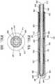
- Figure 5Aillustrates an enlarged longitudinal cross-sectional view of the assembled distal end segment of the optical fiber with spacer assembly 1 disclosed herein.
- Figure 5B - 5Eare axial cross-sections of the distal section of Figure 5A taken along lines A-A, B-B, C-C and D-D, respectively.
- fiber 3 with its fiber core 5, cladding 10 and outer jacket 9is coaxially surrounded by adhesive layer 39, which ensures a secure attachment to outer protective sleeve 19.
- fiber core 5 and cladding 10are coaxially surrounded by sealant 35.
- FIG. 5Dillustrates the bare fiber core 5, reflective air gap 31, inner glass sleeve 13, outer air gap 41, and outer protective sleeve 19.
- Figure 5Edepicts the fused distal end section 29, comprised of the bare fiber core 5 fused together with the inner glass sleeve 13 as previously described and outer air gap 41 coaxially surrounded by the outer protective sleeve 19.
- the laser energytravels down the fiber core 5, as it passes through Section A-A, the laser energy is directed in a forward direction by the cladding 10 and protective jacket 9. As the wave reaches Section B-B, the cladding 10 and sealant 35 ensure a continued forward travel of the energy.
- the silicone sealantprovides additional protection by preventing laser energy from passing through any cracks or openings in the cladding inadvertently created during the manufacturing process.
- any errant laser energy passing through and out of the side wall of core 5 due to the absence of cladding 10will be reflected back into the core 5 by air gap 31 due to its lower index of refraction.
- the laser beamwill pass through the fused distal end section 29 and be directed in a forward direction through energy emitting face 11A.
- Figure 6A through 6Cillustrate the laser fiber 3 with energy emitting faces having several different surface areas and demonstrating the relationship between an increased surface area of the emitting face of the fiber and the average power density reduction.
- Figure 6Ais a partial plan view of the distal section of a conventional 600 micron fiber having a core 5 of diameter D1 with cladding 10 extending to the distal energy emitting face 11.
- Rays 71depict the boundaries of the energy emission zone with a maximum propagation angle ⁇ of energy emitted from the core 5.
- Angle ⁇is based on the numerical aperture of the fiber and the specific materials (core and cladding) being used.
- the propagation angle ⁇may be 16 degrees in water or blood, resulting in laser energy being distributed and emitted across the entire face 11 of the fiber, defined by diameter E1.
- D1is equal to energy emitting face 11 diameter E1.
- the average density of the laser energy at the emitting face 11is based on the surface area of the face 11. For example, a 600 micron fiber has a surface area of about 0.0028 cm2, as shown in Table 1 below. At a power setting of 14 Watts, laser energy is emitted through the energy emitting face 11 at an average power density of 5 KWatts / cm2.
- Table 1 belowillustrates the reduction in power density at the distal end of the fiber as the effective diameter (E) of the energy emitting face 11A is increased.
- the fusion length (L)is listed in microns.
- the diameter of the effective emitting face Eis recorded in microns.
- the surface area of the emitting face 11Ais recorded in cm2. Due to the arcuate surface profile of the fused distal end section 29, the surface area data in Table 1, which is calculated using the area of a circle across a flat horizontal plane, represents the minimum surface area of energy emitting face 11A because it does not account for the additional surface area due to the convex profile of 11A.
- Average power density at the energy emitting face 11Ais recorded in KWatts / cm2 and is based on an average power delivery of 14 Watts, the level commonly used for endovenous laser procedures, divided by the surface area of the emitting face.
- the recorded percent reduction in power densityis relative to that of a conventional 600 micron fiber depicted in Figure 6A , and is calculated as 100 - (average power density / 5.0).
- Figure 6Bis a plan view of the distal section of inner glass sleeve 13 and fiber 3 subassembly after the inner sleeve 13 and fiber 3 have been fused to form tip 29 using a laser fusion process.
- This figureillustrates the increase in the emitting face 11A surface area.
- the fiber core 5is 600 microns with a diameter D1, equal to the conventional fiber core diameter D1 described in Figure 6A .
- the maximum propagation angle ⁇ emitted from the fused distal end 29remains 16 degrees due to the core's numerical aperture of 0.37.
- the laser processfuses the inner glass sleeve 13 and the fiber core 5 creating a fusion length L1 that extends from the fused fiber tip section 29 of the fiber 3 to the distal end of the air gap cavity 31.
- the fusion length L1increases the effective surface area of the emitting face 11A, as indicated by effective diameter E2 of the emitting face 11A, which is larger than the fiber emitting face 11 diameter of E1 of Figure 6A .
- a fusion length L1 of 341 micronswill increase the effective diameter E2 of the emitting face 11A from 600 microns to 780 microns.
- the surface areawill increase from 0.0028 cm2 to 0.0048 cm2.
- the average power densityis reduced due to the increased surface area of the face 11A from 5.0 to 2.9 KWatts / cm2, representing a 40.5% reduction in power density as compared to the conventional fiber of Figure 6A .
- Figure 6Cillustrates a further increased fusion length L2.
- the fiber core 5is 600 microns and has a diameter D1 equal to the core diameter of Figure 6A .
- the laser fusion processcreates a fusion between the inner glass sleeve 13 and the fiber core 5 with a fusion length L2 extending from the fused distal end section 29 to the distal end of the air gap cavity 31.
- the diameter of the energy emitting face 29has increased relative to diameter E1 of Figure 6A and E2 of Figure 6B . This increase in diameter to E3 results in an increased surface area and reduced average power density at the emitting face 29.
- a fuse length L2 of 833 micronswill increase the effective diameter of the emitting face 11A from 600 microns to 1040 microns.
- the surface areawill increase from 0.0028 cm2 to 0.0085 cm2.
- the average power densityis reduced relative to a standard 600 micron core fiber due to the increased surface area of the face 11A from 5.0 to 1.6 KWatts / cm2, representing a 66.7% reduction in average power density as compared to the conventional fiber illustrated in Figure 6A .
- an increase surface area of the fused energy-emitting face 11Ais realized.
- the increased surface area of the fused emitting face 11Aresults in a substantial reduction in average power density at the emitting face 11A of the device without compromising the total amount of energy delivered to the vessel.
- a 75% reduction in average power densitycan be realized.
- the reduced average power density at the distal end of the fiber resulting from an increased surface area of the emitting facereduces peak temperatures and reduces the possibility of thermal run-away and device damage, without a decrease in the total amount of energy delivered during the treatment session.
- the reduced average power densityalso reduces the possibility of vessel perforations caused by extreme temperatures, leading to less bruising, post-operative pain and other clinical complications.
- FIG. 7is an enlarged partial plan view of the distal section of the device of the fiber with spacer assembly 1.
- the outer protective sleeve 19is assembled as previously described with adhesive 39 and crimp area 33, ensuring attachment to the fiber 3/ inner glass sleeve 13 assembly.
- Laser energyis emitted from the distal end of the fiber with a maximum propagation angle ⁇ of the energy emission zone is defined by boundary rays 71.
- Laser energypasses through fused end section 29, is emitted out of emitting face 11A and into and through the lumen 27 of outer protective sleeve 19 at maximum angle ⁇ .
- outer boundary rays 71do not contact the inner wall or leading edge 21 of outer protective sleeve 19.
- the inner glass sleeve 13 / fiber core 3 fusion length L3determines length L4, defined as the length between the distal most edge of the fused end section 29 and the leading edge 21 of the outer protective sleeve 19.
- L4represents the maximum extension of the outer protective sleeve 19 that can be used such that the laser energy exiting the emitting face 11A at the maximum angle ⁇ does not contact the inner wall of outer protective sleeve 19.
- the outer protective sleeve 19may have a light-reflective coating such as gold. This coating may also be applied to a portion of the inner wall of the outer protective sleeve 19 along length L4. When a peripheral portion of the emission zone 71 beyond the emitting face 11A overlaps or otherwise contacts the distal portion of the inner wall of sleeve 19, the optional coating may increase reflection of laser energy into the vessel. Specifically any laser energy contacting the L4 portion of the sleeve 19 will be reflected off the sleeve and back into the treatment regions by the reflective qualities of the coating thereby avoiding emission energy loss and/or minimizing thermal build-up at the distal end of the device.
- a light-reflective coatingsuch as gold. This coating may also be applied to a portion of the inner wall of the outer protective sleeve 19 along length L4.
- the optional coatingmay increase reflection of laser energy into the vessel. Specifically any laser energy contacting the L4 portion of the sleeve 19 will be reflected off the s
- Figure 8Ais a partial longitudinal cross-sectional view of the distal segment of element 201.
- Figure 8Bshows an end view of the embodiment in Figure 8A illustrated from the distal end of the device.
- the components in assembly 201are of a smaller size and diameter compared to optical fiber with spacer assembly 1 of Figure 5 to allow for direct advancement through the treatment vessel without the use of a treatment sheath or other tracking accessory.
- Fiber with spacer element 201includes fiber 203, inner glass sleeve 213 and outer protective sleeve 219.
- the fiber 203 with protective jacket layer 209 and cladding 210extends partially through the outer protective sleeve 219.
- the protective jacket layer 209terminates at distal end 212, adjoining air gap 237.
- the cladding 210terminates just inside the inner glass sleeve 213 at the internal taper 232.
- Inner glass sleeve 213coaxially surrounds fiber core 205 between which a constant-width annular air gap 231 is formed.
- the fiber core 205further extends distally terminating at fused distal end section 229 in emitting face 11A.
- Coaxially positioned in surrounding relationship with the fiber / inner glass sleeve subassemblyis the outer protective sleeve 219.
- Outer protective sleeve 219extends distally beyond fused emitting face 11A terminating in leading edge 221.
- the fiber core 205is comprised of pure silica with a numerical aperture of 0.37 and may have a diameter of 500 microns or less, such as 400 microns.
- Corresponding outer diameter dimensions of other elementsinclude the cladding 210 at 430 microns and outer jacket layer 209 at 620 microns, both of which extend distally into the outer protective sleeve 219.
- Outer jacket 209terminates at point 212 and the cladding 210 terminates within the inner glass sleeve 213 just distal of the inner glass sleeve tapered wall section 232.
- inner glass sleeve 213may have an outer diameter of 1,0922 mm (0.043 inches).
- Inner glass sleeve 312may have an internal through lumen of approximately 0,4191 mm (0.0165 inches) in diameter tapering outwardly to a flared diameter of 0,508 mm (0.020 inches) at proximal edge 232, an outer diameter of 0,8382 mm (0.033 inches) and a length of 6,0452 (0.238 inches).
- the outer protective sleeve 219has an internal through lumen 227 with a diameter of about 0,889 mm (0.035 inches) With these dimensions, the annular air gap 231 is approximately 0,00254 mm (0.0001 inches) in width, and as previously described, is closed at the proximal end by cladding 210 and silicone sealant ring 235 and by the fused inner glass sleeve / fiber tip 229 at the distal end.
- the distal end view of the deviceillustrates the fused distal end section 229 with energy emitting face 11A coaxially surrounded by the outer protective sleeve 219.
- a small air gap 241exists between fused end section 229 and sleeve 219.
- Shown with hidden linesis the air gap 231 which coaxially surrounds the fiber core 205 and the outer boundary of the energy emitting face 11A.
- the expanded distal end 226 of sleeve 219is illustrated by apex 243.
- outer protective sleeve 219is comprised of a proximal edge 223, a cylindrical main body 224, an outwardly bulging distal body/portion 226 extending from the main body, with a through lumen 227 of constant diameter of approximately 0,889 mm (0.035 inches) extending from edge 223 to tip 221.
- the bulging distal body 226has a bulb-like profile or shape.
- the main body 224may be approximately 9,144 mm (0.360 inches) in length.
- the outwardly bulging body 226extends distally from the main body 224 for approximately 1,016 mm (0.040 inches).
- Outwardly bulging distal body 226includes a radially outwardly tapering section 245, which in one aspect may have a taper angle of 170 degrees relative to the longitudinal axis of fiber core 205.
- Tapering section 245extends outwardly to a maximum diameter at apex 243, which in the instant embodiment may have an outer diameter of 1,3716 mm (0.054 inches).
- the wall thickness of sleeve 19may be approximately 0,2413 mm (0.0095 inches), which is approximately twice the thickness of the main body wall which is approximately 0,1397 mm (0.0055 inches).
- the outwardly bulging distal body 226tapers radially inward from apex 243 to distal end 221, which may be radiused to eliminate any sharp edges and provide a smooth leading tip.
- the increased wall thickness and surface area of the bulging distal body 226 relative to the main body 224provides enhanced trackability when inserting and advancing the fiber 203 to the treatment location.
- the distal end segment 226acts as an atraumatic leading tip, which will not perforate the vessel wall if contact is made between outer protective sleeve 219 and the vessel wall during advancement through the vein.
- the additional surface area and material at the distal end of the devicealso provides enhanced trackability and pushability through the vessel.
- the additional material at the distal body 226 of sleeve 219adds structural strength to the distal end of the device making it less susceptible to thermal damage by reducing peak temperatures at the distal end of the device.
- a smaller fibersuch as a 400 micron fiber provides a sufficiently flexible fiber shaft to allow insertion and advancement through the vein without having to use a guidewire or treatment sheath. Due to the small diameter, the fiber with spacer assembly 201 may be inserted directly through a micro-access set into the vein, thereby eliminating several procedural steps as will be described in more detail below.
- a 400 micron fiberis also capable of delivering sufficient energy to cause vessel occlusion. It may be desirable to use a fiber with a diameter of 430 microns to provide additional fiber core diameter at the proximal end where the fiber connects to a laser source. The larger diameter core will allow for slight misalignment of the fiber core to laser source without compromising energy transmission or damaging the laser generator.
- Figure 9Ais a partial plan view of the fiber with spacer assembly illustrating a fiber 3 and proximal section of the outer protective sleeve 19.
- Fiber 3is comprised of a core 5, a cladding layer 10, coaxially surrounded by protective jacket 9, and attached to outer protective sleeve 19 as previously disclosed.
- the devicemay include visual markings/markers 18 on the outer jacket 9 of fiber 3. Markings 18 are used by the physician to provide a visual indication of insertion depth, tip position and speed at which the device is withdrawn through the vessel during delivery of laser energy.
- the markings 18may be numbered to provide the physician with an indication as to distance from the protective sleeve 19 and/or the emitting face 11A of the fiber to the access site during pullback.
- the markings 18may be positioned around the entire circumference of the fiber shaft or may cover only a portion of the shaft circumference.
- the markingsappear at the skin surface through the access site and provide the physician with a visual indication of pullback speed.
- the rate at which the device is retractedis approximately 5 - 8 seconds per cm.
- markings 18may be approximately 1mm in width and be aligned at 1 cm increments.
- the distal most set of markings 59may be uniquely configured to visually alert the physician that the distal end of the fiber with the outer protective sleeve 19 is near the access site, indicating that the procedure is complete.
- FIG. 9Billustrates yet another embodiment of the fiber with spacer assembly 1.
- a metallic reinforcement element 20coaxially surrounds fiber 3 and extends from the proximal end of the fiber (not shown) to the distal end section adjacent to or overlapping with the optional outer protective sleeve 19.
- Metallic reinforcement element 20may be comprised of metallic strands 69 arranged in an overlapping braided pattern, as shown in Figure 9B , or other patterns such as spiral or longitudinal or horizontally arranged strands.
- strands 69are embedded within a polymer layer 79.
- Layer 79may be an extruded urethane, Teflon shrink tubing or other plastic material known in the art.
- metallic reinforcement element 20may be hydrophilically coated to reduce friction during advancement and retraction of the fiber.
- metallic strands 69may optionally overlap with the proximal section of outer protective sleeve 219. Overlapping metallic strands 40 may be sandwiched between the inner wall of outer protective sleeve 219 and the fiber jacket 9. The polymer layer 79 may optionally be removed from the metallic strands 40 and the strands welded to the outer protective sleeve 19.
- Metallic reinforcement element 20provides several advantageous functions. Visibility of the entire fiber shaft 3 under ultrasound imaging is enhanced due to the echogenicity of the metallic strands 69. Enhanced visibility of the fiber shaft provides the physician with an ultrasonically visible target when injecting tumescent fluid into the anatomical peri-venous sheath along the length of the vein prior to the delivery of laser energy, as is described in more detail below. Enhanced visibility of the fiber shaft provides the physician with a visual target for positioning the tumescent injection needle accurately between the outer vein wall and the perivenous sheath without entering the vein lumen.
- the presence of the metallic reinforcement element 20provides an added level of protection to the fiber shaft to prevent damage to the cladding 10 and core 5 from the sharp needle tip.
- tumescent fluidis injected all along the vessel being treated using a small gauge needle.
- the needle tipmay inadvertently contact the fiber shaft during this step, causing damage.
- the additional reinforcement layerprevents the needle from damaging the protective jacket 9 and the cladding 9, thereby preventing the possibility of laser energy escaping radially from the fiber core 5 through the compromised jacket or cladding.
- the optional weld between the outer protective sleeve 19 and the bare metallic strands 40increases the overall structural integrity of the distal end segment by providing a supplemental attachment region.
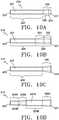
- FIGS 9B through 9DOther outer protective sleeve 19 configurations are illustrated in Figures 9B through 9D .
- the sleeve 319 profilemay include a bulging distal end segment/portion 326 as shown in Figure 9B .
- distal end segment 326includes an outwardly tapering section (conical shape portion) 334 which transitions to cylindrical segment 332, which has a constant diameter, before terminating in radiused end 321.
- Figure 9Cillustrates a plan view of outer protective sleeve 419 showing a bulging distal end segment/portion 426 that extends from main body 424 radially outward at a constant angle (conical shape portion) before terminating in radiused end tip 421.
- Figure 9Dillustrates yet another embodiment of sleeve 519.
- the sleeveincludes a cylindrical portion 524A and an outwardly bulging portion 526A, 524B and 526B.
- Conical shape portion 526Aextends distally from the cylindrical portion 524A with increasing diameter.
- Cylindrical portion 524Bextends from conical shape portion 526A and has a larger diameter than that of cylindrical portion 524A.
- Second conical shape portion 526Bextends from cylindrical portion 524B and has a radiused end (distal tip) 521.
- a through lumen 527extends from distal tip 521 and includes an internal transition from a larger diameter section 527A to a smaller diameter section 527B before terminating at proximal end 523.
- This embodimentmay be used to accommodate a larger inner diameter inner glass sleeve relative to the fiber outer diameter.
- the multiple tapered segments of Figure 9Dalso provide a more gradual taper transition across the entire longitudinal length of the outer protective sleeve 519, which allows for both enhanced tracking of the device to the target treatment location and enhanced retracting of the device through the vein during laser delivery.
- Figure 10A and 10Bdepict the fiber assembly 601 in which the inner glass sleeve 613 is illustrated as an additional embodiment.
- the embodiment of Figure 10is similar to that of Figures 2 and 3 , except that the sleeve 613 has a closed distal end 627 prior to being fused with the fiber core 5.
- Fiber 3includes a core 5, cladding 10, and outer protective jacket 9 with an energy emitting face 11. Cladding 10 has been partially stripped back to edge 30, and protective jacket 9 has also been partially stripped back to edge 12, as previously described.
- inner glass sleeve 613includes a proximal edge 617, and leading end wall 627 and a cavity 675 extending proximally from wall 627 to edge 617.
- the front emitting face 11 of fiber 3is inserted into and advanced through cavity 675 until it abuts up against wall 627.
- a CO2 laseris then used to heat the two silica components 11 and 627 together to form a single fused end tip (not shown) with a radiused surface profile so that an enlarged emitting face is created.
- the constant-width air gap 631acts as a cladding layer to reduce light transmission loss.
- the fused tipreduces the thermal load (average power density) at the distal tip 627 and prevents erosion of the tip section.
- Figure 11is an enlarged partial plan view of the distal section of the device of the fiber with spacer assembly 1 with an outer protective sleeve 19 whose distal end 21 terminates proximally of the energy emitting face 11A.
- the outer protective sleeve 19may be aligned over the inner glass sleeve 13 so that fused end section 29 of the device extends distally beyond the leading edge 21 of outer protective sleeve 19.
- the leading edge 21 of outer protective sleeve 19may be between 0.5 - 5.0 mm proximal to emitting face 11A.
- the protective spacer 19may be of the same length as previously described or may be shorter in overall length.
- the outer protective sleeve 19is assembled as previously described with adhesive 39 and crimp area 33.
- the outer boundaries of the energy emitting face 11Aare defined by maximum propagation angle ⁇ of the energy emission zone 71.
- the energy emitting face 11Ais protected from contact with the vessel wall by the leading radiused surface 73 of inner sleeve 13.
- the outer protective sleeve 19 in this embodimentensures that laser energy emitting from emitting face 11A will not come into contact or reflect off the distal section of the outer protective sleeve 19, regardless of the maximum propagation angle ⁇ of the energy emission zone.
- the outer protective sleeve 19provides increased structural integrity and strength to the distal section of the device while minimizing overheating of the outer protective sleeve 19 caused by peripheral laser beam contact.
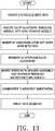
- Figure 12illustrates the procedural steps associated with performing endovenous treatment using the optical fiber with spacer assembly 1.
- the target veinis accessed using a standard Seldinger technique well known in the art. Under ultrasonic guidance, a small gauge needle is used to puncture the skin and access the vein (100). A 0,4572 mm (0.018 inches) guidewire is advanced into the vein through the lumen of the needle. The needle is then removed leaving the guidewire in place (102).
- a micropuncture sheath/dilator assemblyis then introduced into the vein over the guidewire (104).
- a micropuncture sheath dilator setalso referred to as an introducer set, is a commonly used medical kit, for accessing a vessel through a percutaneous puncture.
- the micropuncture sheath setincludes a short sheath with internal dilator, typically 5 - 10 cm in length. This length is sufficient to provide a pathway through the skin and overlying tissue into the vessel, but not long enough to reach distal treatment sites.
- the dilator and 0,4572 mm (0.018 inches) guidewireare removed (105), leaving only the micropuncture introducer sheath in place within the vein (106).
- a 0,889 mm (0.035 inches) guidewireis then introduced through the introducer sheath into the vein.
- the guidewireis advanced through the vein until its tip is positioned near the sapheno-femoral junction or other starting location within the vein (108).
- a treatment sheath/dilator setis advanced over the 0,889 mm (0.035 inches) guidewire until its tip is positioned near the sapheno-femoral junction or other reflux point (112).
- the treatment sheathis of sufficient length to reach the location within the vessel where the laser treatment will begin, typically the sapheno-femoral junction. Typical treatment sheath lengths are 45 and 65 cm.
- the optical fiber with spacer assembly 1is then inserted into the treatment sheath lumen and advanced until the fiber assembly distal end is flush with the distal tip of the treatment sheath (118).
- a treatment sheath/dilator set as described in co-pending U.S. Patent 7,458,967may be used to correctly position the protected fiber tip with spacer assembly 1 of the current invention within the vessel.
- the treatment sheathis retracted a set distance to expose the fiber tip (120), typically 1 to 2 cm. If the fiber assembly has a connector lock as described in U.S. Patent 7,033,347 , the treatment sheath and fiber assembly are locked together to maintain the 1 to 2 cm fiber distal end exposure during pullback.
- the physicianmay optionally administer tumescent anesthesia along the length of the vein (122).
- Tumescent fluidmay be injected into the peri-venous anatomical sheath surrounding the vein and/or is injected into the tissue adjacent to the vein, in an amount sufficient to provide the desired anesthetic effect and to thermally insulate the treated vein from adjacent structures including nerves and skin.
- laser energyis applied to the interior of the diseased vein segment.
- a laser generator(not shown) is turned on and the laser light enters the optical fiber 3 from its proximal end.
- the treatment sheath/fiber assemblyis withdrawn through the vessel at a pre-determined rate, typically 2 - 3 millimeters per second (124).
- the laser energytravels along the laser fiber shaft through the energy-emitting face of the fiber and into the vein lumen, where the laser energy is absorbed by the blood present in the vessel and, in turn, is converted to thermal energy to substantially uniformly heat the vein wall along a 360 degree circumference, thus damaging the vein wall tissue, causing cell necrosis and ultimately causing collapse / occlusion of the vessel.
- the optical fiber with spacer assembly 1has several advantages over methods of use of conventional bare-tipped fibers.
- the energy emitting face of the fiber assemblyis protected from any inadvertent contact with the vessel wall during withdrawal of the device through the vessel during energy delivery. Numerous studies have demonstrated that contact between the energy emitting face of the fiber and the vein wall causes vessel perforations resulting in post-procedural bruising, pain and swelling.
- the inner glass sleeve and optional outer protective sleevefunction to space the energy emitting fiber distal tip away from the vessel wall and to protect the emitting face within the outer protective sleeve recess, thus eliminating any possibility of contact between the fiber emitting face and the vessel and the resulting perforations, even when withdrawing through an extremely tortuous vessel.
- the fiber with spacer assembly 1 of the current inventionalso is advantageous in controlling the direction and density of laser energy emitted from the emitting face of the fiber.
- the inner glass sleeve with annular air gap cavityensures that the laser energy is contained in the fiber core and emitted in a forward direction only. Errant laser energy may compromise the structural integrity of the fiber tip by causing temperature spikes, localized heat build-up at the distal tip section and possible thermal run-away as described above.
- the inner glass sleeve and air gap cavityact to re-direct any errant laser energy back into the fiber core thus preventing reflected laser energy from being absorbed by the outer protective sleeve or other distal end elements.
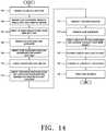
- FIG 13is a flowchart illustrating the procedural steps of the preferred method of endovenous treatment using the optical fiber with spacer assembly 201, which is depicted in Figures 8A and 8B .
- the use of a treatment sheathis not required due to the flexibility and trackability of the smaller diameter fiber device.
- the veinis accessed using a small needle and a 0,4572 mm (0.018 inch) guidewire (100, 102).
- a micropuncture introducer sheath/dilatoris then introduced into the vein over the guidewire (105) to dilate the insertion site. The dilator and guidewire are then removed, leaving the 4F sheath in place.
- the insertion sitedoes not require dilation larger than the diameter of the 4F micropuncture sheath.
- the size of the micropuncture sheath/dilator assemblymay be relatively small and the resulting access site puncture may be reduced relative to conventional methods.
- smaller access sitesare desirable as evidenced by the reduced occurrence of patient complications which may include hematoma, bleeding, pain, access site scarring and infection.
- the 0,4572 mm (0.018 inch) guidewire and dilator/sheathare removed from the patient, after which the optical fiber with spacer assembly is inserted directly into the vein through the 4F micropuncture sheath (119) without the aid of a treatment sheath.
- the fiber assemblyis advanced forward through the vessel using the outwardly bulging distal tip of the outer protective sleeve 19 to facilitate advancement and tracking through tortuous vessels.
- the expanded distal end of the outer protective sleeveprovides an atraumatic leading end, which will not catch or snag on the vessel wall as the fiber assembly is being advanced, but instead will glide along the vein wall.
- the fiber assemblyis smaller and more flexible than larger diameter conventional fibers and can track easily through the vessel without a treatment sheath, numerous conventional procedural steps may be eliminated.
- the step of inserting, advancing and positioning the 0,889 mm (0.035 inches) guidewire at the highest point of reflux within the veinis eliminated.
- the 0,889 mm (0.035 inches) guidewireis required in conventional methods in order to advance a treatment sheath/dilator set through the vessel.
- the steps of inserting a treatment sheath/dilator set, removing the dilator and removing the 0,889 mm (0.035 inches) guidewireare eliminated.
- the fiber assembly according to the present inventionis inserted and advanced in the vessel without these procedure components.
- the steps of retracting the treatment sheath to expose the distal 1 - 2 cm of the fiber and locking the two components together prior to the delivery of laser energyis eliminated.
- misalignment of the fiber tipmay result in thermal energy being transferred to the treatment sheath tip, resulting in potential damage to the treatment sheath and/or patient complications.
- the fiber assemblyis positioned relative to the sapheno-femoral junction or other reflux point without having to align the fiber tip with a treatment sheath tip.
- Laser energyis applied to the interior of the diseased vein segment as the fiber assembly is withdrawn, preferably at a rate of about 2-3 millimeter per second (124).
- the process of controlling the pullback speed through the vessel in conventional methodsis typically controlled by the use of graduated markings on the treatment sheath. Since the treatment sheath is not present with the current method, the physician's pullback speed may be controlled either by markings positioned along the fiber shaft or by using an automated pullback mechanism, as is known in the art.
- the procedure for treating the varicose veinis considered to be complete when the desired length of the target vein has been exposed to laser energy.
- the method of endovenous laser treatment disclosed hereinhas numerous advantages over prior art treatment devices and methods.
- the design of the distal end segment of the fiber assembly with its inner glass sleeve and optional outer protective sleeveprovide the benefits previously described.
- the fiber with spacer assembly, with its smaller fiber size and atraumatic leading distal tipresult in the elimination of multiple procedure steps required in conventional methods.
- Accessory componentssuch as the 0,889 mm (0.035 inch) guidewire, treatment sheath and fiber/sheath locking connections are eliminated, thus reducing the overall cost of the device and procedure. Since the procedure has been simplified, the time associated with the eliminated steps is saved resulting in a faster, safer and more cost-effective procedure.
- the leading atraumatic distal tipnot only provides a mechanism for easily tracking and advancing the fiber assembly in an atraumatic way through tortuous anatomy, but also facilitates the alignment of the fiber emitting face relative to the source of reflux, due to the enhanced ultrasonic visibility of the distal tip section.
Landscapes
- Health & Medical Sciences (AREA)
- Surgery (AREA)
- Life Sciences & Earth Sciences (AREA)
- Physics & Mathematics (AREA)
- Public Health (AREA)
- Medical Informatics (AREA)
- Nuclear Medicine, Radiotherapy & Molecular Imaging (AREA)
- Veterinary Medicine (AREA)
- Engineering & Computer Science (AREA)
- Biomedical Technology (AREA)
- Heart & Thoracic Surgery (AREA)
- General Health & Medical Sciences (AREA)
- Molecular Biology (AREA)
- Animal Behavior & Ethology (AREA)
- Otolaryngology (AREA)
- Optics & Photonics (AREA)
- Electromagnetism (AREA)
- Oral & Maxillofacial Surgery (AREA)
- Pathology (AREA)
- Laser Surgery Devices (AREA)
Description
- The present invention relates to a medical device for treating blood vessels, and more particularly to a laser treatment device for causing closure of varicose veins.
- Veins are thin-walled and contain one-way valves that control blood flow. Normally, the valves open to allow blood to flow into the deeper veins and close to prevent back-flow into the superficial veins. When valves are malfunctioning or only partially functioning, however, they no longer prevent the back-flow of blood into the superficial veins. As a result, venous pressure builds at the site of the faulty valves. Because the veins are thin walled and not able to withstand the increased pressure, they become what are known as varicose veins which are veins that are dilated, tortuous or engorged.
- In particular, varicose veins of the lower extremities is one of the most common medical conditions of the adult population. It is estimated that varicose veins affect approximately 25% of adult females and 10% of males. Symptoms include discomfort, aching of the legs, itching, cosmetic deformities, and swelling. If left untreated, varicose veins may cause medical complications such as bleeding, phlebitis, ulcerations, thrombi and lipderatosclerosis.
- Endovascular thermal therapy is a relatively new treatment technique for venous reflux diseases such as varicose veins. With this technique, the thermal energy is delivered by a flexible optical fiber or radiofrequency electrode that is percutaneously inserted into the diseased vein prior to energy delivery. For laser delivery, a treatment sheath is typically inserted into the vein at a distal location and advanced to within a few centimeters of the source of reflux. Once the treatment sheath is properly positioned, a flexible optical fiber is inserted into the lumen of the treatment sheath and advanced until the fiber tip is near the treatment sheath tip but still protected within the sheath lumen.
- Prior to laser activation, the treatment sheath is withdrawn approximately 1-4 centimeters to expose the distal tip of the optical fiber. After the fiber tip has been exposed a selected distance beyond the treatment sheath tip, a laser generator is activated causing laser energy to be emitted from the bare flat tip of the fiber into the vessel. The emitted energy heats the blood causing hot bubbles of gas to be created. The gas bubbles transfer thermal energy to the vein wall, causing cell necrosis, thrombosis and eventual vein collapse. With the laser generator turned on, both the optical fiber and treatment sheath are slowly withdrawn as a single unit until the entire diseased segment of the vessel has been treated.
- A typical laser system uses a 600-micron optical fiber covered with a polymer jacket and cladding layer. The fiber core extends through the fiber terminating in an energy emitting face.
- With some prior art treatment methods, contact between the energy-emitting face of the fiber optic tip and the inner wall of the varicose vein is recommended to ensure complete collapse of the diseased vessel. For example,
U.S. Pat. No. 6,398,777, issued to Navarro et al , teaches either the means of applying pressure over the laser tip or emptying the vessel of blood to ensure that there is contact between the vessel wall and the fiber tip. One problem with direct contact between the laser fiber tip and the inner wall of the vessel is that it can result in vessel perforation and extravasation of blood into the perivascular tissue. This problem is documented in numerous scientific articles including "Endovenous Treatment of the Greater Saphenous Vein with a 940-nm Diode Laser: Thrombotic Occlusion After Endoluminal Thermal Damage By Laser-Generated Steam Bubble" by T. M. Proebstle, MD, in Journal of Vascular Surgery, Vol. 35, pp. 729-736 (April, 2002), and "Thermal Damage of the Inner Vein Wall During Endovenous Laser Treatment: Key Role of Energy Absorption by Intravascular Blood" by T. M. Proebstle, MD, in Dermatol Surg, Vol. 28, pp. 596-600 (2002). When the fiber contacts the vessel wall during treatment, intense direct laser energy is delivered to the vessel wall rather than indirect thermal energy from the gas bubbles from heating of the blood. Laser energy in direct contact with the vessel wall causes the vein to perforate at the contact point and surrounding area. Blood escapes through these perforations into the perivascular tissue, resulting in post-treatment bruising and associated discomfort. - Another problem created by the prior art methods involving contact between the fiber tip and vessel wall is that inadequate energy is delivered to the non-contact segments of the diseased vein. Inadequately heated vein tissue may not occlude, necrose or collapse, resulting in incomplete treatment. With the fiber tip in contact with the vessel wall rather than the bloodstream, hot gas bubbles are not created. The bubble is the mechanism by which the 360 degree circumference of the vessel wall is damaged. Without the bubbles, it is possible for some vein tissue to be under heated or not heated at all, resulting in incomplete treatment and possible recanalization of the vessel.
- A related problem with endovascular laser treatment of varicose veins using a conventional fiber device is fiber tip damage during laser energy emission caused by localized heat build up at the working end of the fiber, which may lead to thermal runaway. Thermal runaway occurs when temperature at the fiber tip reaches a threshold where the core and/or cladding begin to absorb the laser radiation. As the fiber begins to absorb the laser energy it heats more rapidly, quickly spiraling to the point at which the emitting face begins to burn back like a fuse. One cause of the heat build up is the high power density at the emitting face of the fiber. A conventional fiber includes a cladding layer immediately surrounding the fiber core. Laser energy emitted from the distal end of the device may create thermal spikes with temperatures sufficiently high to cause the cladding layer to burn back. Once the cladding layer is no longer present, laser energy will travel through the side wall of the fiber, causing additional energy loss and localized heating. The fiber weakens under the high temperatures and may break.
- In a related problem with conventional endovenous laser treatment methods, numerous procedural steps and accessory components are required to correctly position the optical fiber at the treatment site prior to the application of laser energy. The procedure is time-consuming and expensive partially due to the costs of the accessory components, which includes a treatment sheath designed to provide a pathway for the fiber to be advanced through the vessel to the source of reflux. The introduction of multiple components including the treatment sheath requires a large access site puncture which may result in patient complications including bruising, prolonged bleeding, scarring, and infection.
- Therefore, it would be desirable to provide an endovascular treatment device and method that protects the emitting face of the optical fiber from direct contact with the inner wall of vessel during the emission of laser energy to ensure consistent thermal heating across the entire vessel circumference thus avoiding vessel perforation and/or incomplete vessel collapse.
- It is also desirable to provide an endovascular treatment device and method which decreases peak temperatures at the working end of the fiber during the emission of laser energy thus avoiding the possibility of fiber damage and/or breakage due to heat stress caused by thermal runaway.
- It is yet another purpose to provide an endovascular treatment device and method which reduces the number of accessory components and procedural steps required to successfully treat a blood vessel.
- Various other purposes and embodiments of the present invention will become apparent to those skilled in the art as more detailed description is set forth below. Without limiting the scope of the invention, a brief summary of some of the claimed embodiments of the invention is set forth below. Additional details of the summarized embodiments of the invention and/or additional embodiments of the invention may be found in the Detailed Description of the Invention.
US6282349 describes a launch fiber termination.US2006/0085024 describes a medical balloon.EP0208175 describes a light transmitting apparatus.US5291570 describes a high power laser-optical fiber connection system. - According to the present invention, there is provided an endovascular laser treatment device for causing closure of a blood vessel according to
Claim 1. Preferred embodiments of the invention are provided in the dependent claims. - As can be appreciated, the enlarged light emitting face provides substantially lower power density while providing the same amount of total energy during a treatment session. The reduced power density reduces peak temperatures near the emitting face and prevents thermal runaway and device damage. The reduced average power density from the enlarged emitting face and the spacing of the emitting face away from the vessel wall due to the outer sleeve both serve to reduce the possibility of vessel perforations, leading to less bruising, post-operative pain and other clinical complications.
- An endovascular treatment method for causing closure of a blood vessel, not according to the present invention, is provided. The method involves inserting into a blood vessel an optical fiber having a core and a spacer sleeve arranged around a distal portion of the core. The distal end of the fiber core defines a light emitting face. Once the optical fiber is inserted, a laser light is applied through the light emitting face while the inserted optical fiber and spacer sleeve are moved longitudinally to treat a defined segment of the blood vessel. The application of laser light causes closure of the blood vessel. Advantageously, the spacer sleeve positions the light emitting face away from an inner wall of the blood vessel, thereby reducing the possibility of vessel wall perforations and less bruising.
- In yet another aspect, the spacer comprises an inner sleeve and an outer sleeve both arranged around a distal portion of the core to prevent the laser light from traveling laterally and to position the light emitting face away from an inner wall of the vessel. The inner sleeve can be a heat resistive material such as ceramic and the outer sleeve can be, for example, a metallic sleeve to provide structural integrity and strength to the distal section of the treatment device. The outer sleeve can be especially important when the inner sleeve is a ceramic material. Because the ceramic material is brittle, portions of the material can come apart due to heat stress and the outer sleeve surrounding the inner sleeve can help dissipate heat and prevent loose ceramic parts from traveling into the blood vessel, which can be very dangerous.
- The foregoing purposes and features, as well as other purposes and features, will become apparent with reference to the description and accompanying figures below, which are included to provide an understanding of the invention and constitute a part of the specification, in which like numerals represent like elements, and in which:
Figure 1A is a longitudinal plan view of the distal section of the optical fiber with spacer assembly.Figure 1B is a partial cross-sectional view of the distal section of the optical fiber with spacer assembly.Figure 2 depicts longitudinal plan views of the components of the distal section of the fiber with spacer assembly prior to assembly including the optical fiber, the inner glass sleeve and the outer protective sleeve.Figure 3A is a partial plan view of the distal section of the fiber and inner glass sleeve subassembly prior to fusing.Figure 3B is a partial plan view of the distal section of the fiber with inner glass sleeve subassembly after fusing of the distal end.Figure 4 is a partial plan view of the distal section of the fiber, inner glass sleeve assembled with the outer protective sleeve.Figure 5A illustrates a detailed longitudinal cross-sectional view of the distal section of the optical fiber with spacer assembly.Figure 5B through 5E are cross-sections ofFigure 5A taken along lines A-A, B-B, C-C and D-D.Figure 6A is a partial plan view of the distal section of a conventional prior art fiber illustrating the maximum propagation angle θ of the laser beam given an emitting face diameter of E1.Figure 6B is a partial plan view of the distal section of the optical fiber/ inner glass sleeve subassembly illustrating the relationship between weld length L1 and an increase in surface area of the emitting face E2.Figure 6C is a partial plan view of the distal section of the optical fiber/ inner glass sleeve assembly illustrating the relationship between weld length L2 and an increase in surface area of the emitting face E3.Figure 7 is a partial plan view of the distal section of the optical fiber with spacer assembly illustrating the maximum propagation angle exiting from the outer protective sleeve lumen.Figure 8A is a partial longitudinal cross-sectional view of the distal segment of an alternative embodiment of an optical fiber with spacer assembly.Figure 8B is an end view of the embodiment ofFigure 8A shown from the distal end of the device.Figure 9A is a partial plan view of a one embodiment of the fiber shaft illustrated with the distal section of the outer protective sleeve.Figure 9B is partial plan view of another embodiment of the fiber shaft illustrated with the distal section of the outer protective sleeve.Figure 10A through 10D illustrate various embodiments of the outer protective sleeve.Figure 11A depicts a partial plan view of the distal section of the fiber with a plan view of an alternative embodiment of the inner glass sleeve.Figure 11B illustrates the subassembly of the fiber and inner glass sleeve ofFigure 11A .Figure 12 is a partial plan view of the distal section of the optical fiber with spacer assembly depicting an alternative embodiment of the outer protective sleeve.Figure 13 is a flowchart depicting the method steps for performing endovenous laser treatment using the device ofFigure 5 .Figure 14 is a flowchart depicting the method steps for performing endovenous laser treatment using the device ofFigure 8A .- The following detailed description should be read with reference to the drawings, in which like elements in different drawings are identically numbered. The drawings, which are not necessarily to scale, depict selected preferred embodiments and are not intended to limit the scope of the claims. The detailed description illustrates by way of example, not by way of limitation, the principles of the invention. In various embodiments, and referring to
Figures 1-14 , presented herein are exemplary devices and methods for endovenous laser treatment.Figures 1A and 1B illustrate the distal section of one embodiment of the optical fiber withspacer assembly 1 from a partial plan view and partial cross-sectional view, respectively. Optical fiber withspacer assembly 1 is comprised of anoptical fiber 3, an insulativeinner sleeve 13 and an optional outerprotective sleeve 19 coaxially surrounding theinner insulative sleeve 13 and the distal portion of theoptical fiber 3. The spacer assembly includes theinner sleeve 13 andouter sleeve 19. Theoptical fiber 3 is comprised of acore 5,cladding layer 10 and aprotective fiber jacket 9 surrounding thecladding layer 10. As disclosed herein, the fiber core may range from 200 - 1000 microns in diameter. In one exemplary aspect, thecore 5 is 600 microns. - The
protective jacket 9, which can be susceptible to burn-back during operation, may be stripped back from the emittingface 11 of thefiber 3 for a length of approximately 9 mm to where theproximal edge 17 of insulativeinner sleeve 13 abuts up againstprotective jacket 9 of thefiber 3. Outerprotective sleeve 19 extends from its distalmost edge 21 proximally over thefiber core 5 and a portion of the cladding and jacketed section of thefiber 3, terminating inproximal end 23. - In the embodiment shown in
Figures 1A and 1B , thefront emitting face 11 ofoptical fiber 3 is recessed from thedistal end 15 of insulativeinner sleeve 13 and further recessed from thedistal end 21 ofprotective spacer sleeve 19. This configuration, with its heat insulating properties helps to reduce temperatures at the distal end of the device, in turn preventing thermal runaway and possible melting of the core. In addition, the multi-layer design acts as a spacer to prevent contact between the front emittingface 11 of thefiber 3 and the vessel wall, as will be explained in more detail below. - In one exemplary aspect, the axial distance between the
energy emitting face 11 of theoptical fiber 3 and thedistal end 15 of the insulative inner glass sleeve after assembly is approximately 0.1524 mm (0.006 inches). This distance may range from flush with the emittingface 11 to approximately 0.024 inches and may be in one aspect from about 0,0762 mm (0.003 inches) to about 0,6096 mm (0.024 inches). Generally, the distance is equal to approximately half the cross-sectional diameter of thefiber core 5. The insulativeinner sleeve 13 functions as a spacer by preventing any laser energy from being emitted from the side wall of thefiber core 5. Innerinsulative sleeve 13 minimizes heat transmission at the distal end of the device, as will be described in more detail below. In the embodiment depicted inFigure 1A and 1B , theinner insulative sleeve 13 may be ceramic or other type of high-temperature resistant materials such as, but not limited to carbon or silica while theouter sleeve 19 may be a metallic sleeve such as a stainless steel sleeve to provide structural integrity to the spacer assembly and enhanced ultrasound visibility. - In one exemplary aspect, the axial distance between the distal end of the
energy emitting face 11 anddistal end 21 of the outerprotective sleeve 19 after assembly is approximately 0,6096 mm (0.024 inches). This distance can range from about 0 to about 0,762 mm (about 0 to about 0.030 inches) and in one aspect, from about 0,127 mm (0.005 inches) to 0,6096 mm (0.024 inches). Generally, the distance between the emittingface 11 and thedistal end 21 of the outerprotective sleeve 19 should be selected such that the light emitted from thefiber emitting face 11 does not contact the inner wall of the outerprotective sleeve 19 as it is transmitted from theenergy emitting face 11 of thefiber 3 to the blood vessel lumen. - The
distal end 21 of the outerprotective sleeve 19 may extend approximately 0,1524 mm (0.006 inches) beyond thedistal end 15 of theinsulative sleeve 13 and approximately 0,3048 mm (0.012 inches) beyond the distal end of theenergy emitting face 11. Alternatively, in another aspect, thedistal end 21 of the outerprotective sleeve 19 may be positioned flush with theenergy emitting face 11. In this aspect, the insulativeinner glass sleeve 13 may extend distally beyond theenergy emitting face 11 to shield thefiber core 5, thereby protecting the vessel wall from inadvertent contact with thefiber core 5 emittingface 11. Figure 2 depicts the distal section of the components of an alternative embodiment of optical fiber withspacer assembly 1. The distal end section includesoptical fiber 3, aninner glass sleeve 13 and a protectiveouter sleeve 19 prior to assembly. In one exemplary aspect, the fiber may be a 600 micron fiber, thecore 5 may about 0,60706 mm (0.0239 inches) in diameter and coaxially surrounded by athin cladding layer 10 with a wall thickness of approximately 0,00762 mm (0.0003 inches). Where thecladding 10 is present, the outer diameter of thefiber 3 may be approximately 0,62484 mm (0.0246 inches). With the addition of theprotective jacket layer 9, the overall outer diameter of thefiber 3 is about 1,0414 mm (0.041 inches). Theoptical fiber 3 is shown with theprotective jacket 9 removed from the distal emittingface 11 topoint 12. Thecladding layer 10 is removed from thedistal face 11 topoint 30. The distance between theleading edge 12 of theprotective jacket layer 9 and the leadingedge 30 of thecladding 10 may be between approximately 0.25 mm and 2.00 mm in length. In one exemplary aspect, theoptical fiber 3 has a silica core and a polymer cladding layer (e.g., fluoropolymer). In this aspect, both thejacket 9 andcladding layer 10 are stripped as shown inFigure 2 . In another aspect, the optical fiber may have aglass core 5 and a glass (e.g., doped silica)cladding layer 10. In this aspect, only thejacket 9 is stripped back, although theglass cladding layer 10 may also be stripped.- As illustrated in
Figure 2 , theinner glass sleeve 13 may be comprised of silica (SiO2) or other glass or quartz material compositions with an index of refraction equivalent or close to that of thefiber core 5. Having index-matching materials reduces the Fresnel reflection, which minimizes emission of laser energy through the side surfaces of the core by redirecting the laser beam in a forward direction, as is known in the art. - In one embodiment, the
inner sleeve 13 may be approximately 5,9944 mm (0.236 inches) in length. A throughlumen 25 extends from thedistal edge 15 of theinner glass sleeve 13 to terminate atproximal edge 17. The outer diameter of theinner glass sleeve 13 may be approximately 1,0414 mm (0.041 inches) in order to ensure that the outer surface ofinner sleeve 13 is flush with the outer surface of the unstripped portion ofoptical fiber 3 after assembly, as shown inFigures 1A and 1B . The throughlumen 25 is dimensioned so as to allow the stripped portion of theoptical fiber 3 to be inserted into and through theinner glass sleeve 13. For a standard 600 micron fiber, thelumen 25 ofinner glass sleeve 13 may be dimensioned at about 0,61722 mm (0.0243 inches) to accommodate afiber core 5 diameter of approximately 0,60706 mm (0.0239 inches). In the embodiment shown, theproximal edge 17 ofinner glass sleeve 13 has an expanded luminal diameter which tapers inwardly from a diameter of approximately 0,7112 mm (0.0280 inches) to the nominal through lumen diameter of about 0,61722 mm (0.0243 inches). The internally taperedwall 32 provides for ease of assembly when inserting thefiber core 5 into theinner glass sleeve 13. It also allows for insertion of the leadingedge 30 ofcladding 10 into thesleeve lumen 25 to create an overlapping seal with theinner glass sleeve 13, as is shown more clearly inFigure 3A . - In one aspect, as illustrated in
Figure 2 , outerprotective sleeve 19 is an optional element that may be included in the assembly. Outerprotective sleeve 19 is designed to space theenergy emitting end 11 of the fiber away from the vessel wall to increase the durability of the distal region of theoptical fiber assembly 1, and to enhance tracking through the vessel during the insertion. In one aspect,sleeve 19 may be comprised of a heat conductive metal such as medical grade stainless steel, gold, platinum, or nitinol. These materials will dissipate heat. Alternatively,sleeve 19 may be comprised of heat-resistant materials such as ceramic, high-temperature polymer, carbon or silica. Heat-resistant materials minimize heat transmission to the surface of the sleeve. A combination of heat-conductive and heat-resistant materials may also be used to construct the distal end section of the fiber. - Inherently, a multilayer structure as disclosed herein will increase the visibility of the distal end of
device 1 under ultrasound or other imaging modality. Thesleeve 19 may be coated with a lubricous substance to enhance trackability through the vessel. Outerprotective sleeve 19 may also be coated with a substance, such as titanium nitride (TiN) or gold, to reduce friction between thesleeve 19 and the vessel wall when the distal end of the device increases in temperature, as will be described in more detail below. - In one aspect, outer
protective sleeve 19 includes throughlumen 27 that extends fromdistal edge 21 toproximal edge 23. The diameter oflumen 27 may be is approximately 1,0668 mm (0.042 inches) so as to allow a snug fit when assembled coaxially over theinner glass sleeve 13, which in one exemplary aspect, may have an outer diameter of approximately 1,0414 (0.041 inches). The outerprotective sleeve 19 may be approximately 1.6 cm in length, and when assembled with thefiber 3 andinner glass sleeve 13, extends proximally past the bare fiber section to coaxially surround the distal section of the outerprotective jacket 9. Thedistal end 21 of outerprotective sleeve 19 may be radiused or have an expanded diameter to enhance trackability, as will be discussed in more detail below. Figures 3A, 3B andFigure 4 illustrate the assembly steps for the optical fiber withspacer assembly 1. As depicted inFigure 3A , the first step in the assembly process is to assemble thefiber 3 to theinner glass sleeve 13. Leadingedge 17 ofinner sleeve 13 is first slid over theenergy emitting face 11 of theoptical fiber 3 and advanced until theinternal taper 32 ofinner sleeve 13 contacts the leadingedge 30 of thecladding 10.Inner sleeve 13 is advanced over thefiber core 5 until the leadingedge 30 ofcladding 10 is positioned within thelumen 25 atinternal sleeve taper 32. Once the inner diameter of thetaper 32 reaches about 0,62992 mm (0.0248 inches) thefiber 3 withcladding 10 is prevented from further advancement due to an interference fit, resulting in a small overlap between thecladding 10 andinner glass sleeve 13. The interference fit and overlap between these two components helps to maintain the position of theinner glass sleeve 13 on thefiber 3 during the next assembly step and also to seal off the proximal opening oflumen 25 ofinner sleeve 13.- In one aspect of the
assembly 1, as shown inFigure 3A , an annular constant-width air gap 31 is created between theinner glass sleeve 13 and thefiber core 5. Theair gap 31 may be about 0,00508 mm (0.0002 inches) wide for a 600 micron fiber assembly, based on acore 5 diameter of 0,60706 mm (0.0239 inches) and aninner sleeve 13 diameter of 0,61722 mm (0.0243 inches). At this stage of the assembly process,air gap 31 extends longitudinally from the leadingedge 15 ofinner sleeve 13 to thefront face 30 of thecladding 10. The interference fit between theleading edge 30 of claddedfiber 10 and the taperedsection 32 ofinner glass sleeve 13 creates a seal, effectively closing off the proximal opening ofair gap 31. In one aspect, thefront emitting face 11 of thefiber core 5 may extend distally from the leadingedge 15 of theinner glass sleeve 13. In one embodiment of a 600 micron fiber, thefiber core 5 may extend approximately 1.5 mm distally of theinner glass sleeve 13. - Once the
inner glass sleeve 13 is properly aligned over thefiber 3, thedistal end 15 ofinner sleeve 13 is welded or fused together with the energy-emittingface 11 of thebare fiber core 5 to formdistal end section 29, as shown inFigure 3B . In one aspect, both thefiber core 5 and the inner glass sleeve are composed of equivalent silica material. In one aspect, a CO2 laser may be used to heat the two silica components together to form a single fusedend section 29 with anenergy emitting face 11A. When the silica or other material of theinner glass sleeve 13 is heated by the laser, it melts together with thefiber core 5 material, forming a curved (convex as shown) semi-spherical distal end profile, as shown inFigure 3B . Other distal end profiles may optionally be formed by modifying the fusing process or by post-fusing shaping, using techniques known in the art. Shapes may include but are not limited to generally flat faced, with or without a radiused edge, convex and concave. - In one aspect, the fused
end tip section 29 also effectively blocks the distal end of theair gap 31, creating an enclosed air cavity. Thisenclosed air cavity 31 acts as a cladding by containing light withincore 5 and directing light energy in a forward manner. The cladding of a conventional fiber normally extends distally to just proximal to or flush with the energy emittingfiber core face 11. The cladding prevents emitted laser energy from exiting the side wall of the fiber core as the laser beam travels through the fiber, but the distal end section of the fiber where the energy is emitted, is often subject to localized heating during use. This heat build-up at the distal end section of a conventional fiber may reach temperatures high enough to melt or otherwise damage the fragile cladding layer. Once the cladding has been damaged, laser energy will escape radially through the side wall of thefiber core 5, causing increased localized heating with peak temperatures that may be high enough to further damage the distal end of the fiber. - In one exemplary aspect, the
air gap 31 of the fiber assembly disclosed herein helps to reduce localized heat build-up and prevent thermal damage to the working end of thedevice 1. Since air has a lower refractive index than silica,air gap 31 functions as cladding to prevent laser energy from escaping the core. By removing thecladding 9, the possibility of burn back of the cladding is eliminated. The fusedend tip section 29 ensures that blood will not contact the bare side walls of thefiber core 5. With conventional fibers, when the cladding burns back, blood in contact with the side wall of the bare fiber may carbonize and cause additional laser energy loss through the side wall. Continued energy loss through the side walls of the fiber causes the fiber to weaken and eventually break. Theassembly 1 withair gap 31 eliminates problems due to cladding burn back and ensures that any errant laser energy that does escape through thecore 5 will be reflected back into thecore 5 by the presence ofair gap 31, due to the air index of refraction. Thus, theair gap 31 serves as a "thermal-proof" waveguide to maintain the laser light within thecore 5 as it travels through the unclad portion of thefiber 3 by ensuring that the energy travels in a forward direction and does not escape radially through the core side wall. The energy beam exits from the fuseddistal end section 29 through emittingface 11A of the fiber in a forward direction only. Figure 4 is an enlarged partial longitudinal plan view of the distal end section of the optical fiber withspacer assembly 1 after the optional outerprotective sleeve 19 has been assembled over theinner glass sleeve 13/fiber 3 subassembly ofFigure 3 . Prior to assembling thesleeve 19 with theinner glass sleeve 13/fiber 3 assembly, theproximal end 17 of theinner glass sleeve 13 is sealed against thecladding 10.Sealant 35 is applied to the gap between theleading edge 12 of thejacket 9 and theproximal edge 17 of theinner glass sleeve 13. A curable silicone-based liquid adhesive is applied to the annular gap using a small mandrel or other known application process. In one aspect, the liquid sealant may have a refraction index equivalent to thecladding 10. Thesealant 35 applied to the gap is sufficient to completely seal theedge 17 of theinner glass sleeve 13 against the leadingedge 30 ofcladding 10 as well as to fill the space created by the inwardly taperedsurface 32.Sealant 35 fills any gaps, cracks or other damage that may have occurred to thecladding 10 during the manufacturing process. The adhesive qualities ofsealant 35 provide added strength to the device by increasing the bond strength between the fiber andinner glass sleeve 13. Thus,sealant 35 acts as a supplemental cladding by preventing any laser energy from escaping through thecladding 10 in this area. In one aspect, the amount ofsealant 35 applied may create an outer diameter that is less than or equal to that of theinner glass sleeve 13 andprotective jacket layer 9 of thefiber 3.- Outer
protective sleeve 19 is then aligned over the inner glass sleeve /fiber subassembly so that thedistal end 21 ofsleeve 19 is positioned a distance distal to the emittingface 11A of fusedend tip section 29. This distance may be equal to or greater than zero, such as 0,0762 mm - 0,2032mm (0.003 inches - 0.008 inches) or greater. In one aspect thesleeve 19 is positioned approximately 0,1651 mm (0.0065") from the distal end of the fusedend tip 29. Adhesive may be applied to ensure that the outerprotective sleeve 19 is retained in the desired position during assembly. Specifically, adhesive 39 may be applied to the annular space betweenfiber jacket 9 and the inner wall of outerprotective sleeve 19.Adhesive 39 may also be applied to the proximal section of the annular space between theinner glass sleeve 13 and theouter sleeve 19. As shown inFigure 4 and5 , adhesive 39 extends from the distal edge ofair gap 37 distally toadhesive termination point 40. A ring of adhesive 39 may also be applied to the proximal end of the outerprotective sleeve 19. This ring not only provides enhanced fixation of thesleeve 19 to thefiber 3, but also provides a tapered outer profile to prevent the vein from catching onsleeve 19 as the device is withdrawn from the vessel. - Optionally, the proximal section of the outer
protective sleeve 19 may be crimped atcrimp area 33 to enhance the attachment strength between thesleeve 19 and the jacketedfiber 3. In one embodiment, the crimping process may force the wall of the outerprotective sleeve 19 to be pressed into theadhesive layer 39, as shown byindentions 38 inFigure 5A . Figure 5A illustrates an enlarged longitudinal cross-sectional view of the assembled distal end segment of the optical fiber withspacer assembly 1 disclosed herein.Figure 5B - 5E are axial cross-sections of the distal section ofFigure 5A taken along lines A-A, B-B, C-C and D-D, respectively. Referring toFigure 5B ,fiber 3 with itsfiber core 5, cladding 10 andouter jacket 9 is coaxially surrounded byadhesive layer 39, which ensures a secure attachment to outerprotective sleeve 19. Referring next toFigure 5C ,fiber core 5 andcladding 10 are coaxially surrounded bysealant 35. As withFigure 5B , the outerprotective sleeve 19 coaxially surrounds the subassembly, but theadhesive ring 39 has been replaced withair gap 37.Air gap 37 is optional and is based on the thickness ofsealant 35 applied to thecladding 10 as well as the amount the sealant will shrink after drying.Figure 5D illustrates thebare fiber core 5,reflective air gap 31,inner glass sleeve 13,outer air gap 41, and outerprotective sleeve 19.Figure 5E depicts the fuseddistal end section 29, comprised of thebare fiber core 5 fused together with theinner glass sleeve 13 as previously described andouter air gap 41 coaxially surrounded by the outerprotective sleeve 19.- When laser energy travels down the
fiber core 5, as it passes through Section A-A, the laser energy is directed in a forward direction by thecladding 10 andprotective jacket 9. As the wave reaches Section B-B, thecladding 10 andsealant 35 ensure a continued forward travel of the energy. The silicone sealant provides additional protection by preventing laser energy from passing through any cracks or openings in the cladding inadvertently created during the manufacturing process. As the laser energy passes through Section C-C, any errant laser energy passing through and out of the side wall ofcore 5 due to the absence of cladding 10 will be reflected back into thecore 5 byair gap 31 due to its lower index of refraction. Once the laser energy reaches Section D-D, the laser beam will pass through the fuseddistal end section 29 and be directed in a forward direction throughenergy emitting face 11A. Figure 6A through 6C illustrate thelaser fiber 3 with energy emitting faces having several different surface areas and demonstrating the relationship between an increased surface area of the emitting face of the fiber and the average power density reduction.Figure 6A is a partial plan view of the distal section of a conventional 600 micron fiber having acore 5 of diameter D1 withcladding 10 extending to the distalenergy emitting face 11.Rays 71 depict the boundaries of the energy emission zone with a maximum propagation angle θ of energy emitted from thecore 5. Angle θ is based on the numerical aperture of the fiber and the specific materials (core and cladding) being used. In one exemplary aspect, given a numerical aperture of 0.37, the propagation angle θ may be 16 degrees in water or blood, resulting in laser energy being distributed and emitted across theentire face 11 of the fiber, defined by diameter E1. InFigure 6A , D1 is equal toenergy emitting face 11 diameter E1. The average density of the laser energy at the emittingface 11 is based on the surface area of theface 11. For example, a 600 micron fiber has a surface area of about 0.0028 cm2, as shown in Table 1 below. At a power setting of 14 Watts, laser energy is emitted through theenergy emitting face 11 at an average power density of 5 KWatts / cm2.- Table 1 below illustrates the reduction in power density at the distal end of the fiber as the effective diameter (E) of the
energy emitting face 11A is increased. The fusion length (L) is listed in microns. The diameter of the effective emitting face E is recorded in microns. The surface area of the emittingface 11A is recorded in cm2. Due to the arcuate surface profile of the fuseddistal end section 29, the surface area data in Table 1, which is calculated using the area of a circle across a flat horizontal plane, represents the minimum surface area ofenergy emitting face 11A because it does not account for the additional surface area due to the convex profile of 11A. Average power density at theenergy emitting face 11A is recorded in KWatts / cm2 and is based on an average power delivery of 14 Watts, the level commonly used for endovenous laser procedures, divided by the surface area of the emitting face. The recorded percent reduction in power density is relative to that of a conventional 600 micron fiber depicted inFigure 6A , and is calculated as 100 - (average power density / 5.0).TABLE 1 Power Density Reduction Table For 600 Micron Fiber Core Fusion Length (L) (microns) Effective Diameter of energy emitting face (E) (microns) Surface area of emitting face (cm2) Average Power density (KWatts / cm2) Reduction in average power density 0 600 0.0028 5.0 0% 227 720 0.0041 3.4 31% 265 740 0.0043 3.3 33% 303 760 0.0045 3.1 38% 341 780 0.0048 2.9 41% 416 820 0.0053 2.7 47% 492 860 0.0058 2.4 51% 530 880 0.0016 2.3 54% 606 920 0.0056 2.1 58% 681 960 0.0072 1.9 61% 719 980 0.0075 1.9 63% 795 1020 0.0082 1.7 65% 833 1040 0.0085 1.6 67% 908 1080 0.0092 1.5 69% 984 1120 0.0099 1.4 71% 1022 1140 0.0102 1.4 72% 1098 1180 0.0109 1.3 74% 1135 1200 0.0113 1.2 75% 1211 1240 0.0121 1.2 77% 1249 1260 0.0125 1.1 77% 1325 1300 0.0133 1.1 79% 1400 1340 0.0141 1.0 80% 1476 1380 0.0150 0.9 81% 1514 1400 0.0154 0.9 82% 1590 1440 0.0163 0.9 83% 1627 1460 0.0167 0.8 83% 1703 1500 0.0177 0.8 84% Figure 6B is a plan view of the distal section ofinner glass sleeve 13 andfiber 3 subassembly after theinner sleeve 13 andfiber 3 have been fused to formtip 29 using a laser fusion process. This figure illustrates the increase in the emittingface 11A surface area. In this aspect, thefiber core 5 is 600 microns with a diameter D1, equal to the conventional fiber core diameter D1 described inFigure 6A . The maximum propagation angle θ emitted from the fuseddistal end 29 remains 16 degrees due to the core's numerical aperture of 0.37. As described above, the laser process fuses theinner glass sleeve 13 and thefiber core 5 creating a fusion length L1 that extends from the fusedfiber tip section 29 of thefiber 3 to the distal end of theair gap cavity 31. The fusion length L1 increases the effective surface area of the emittingface 11A, as indicated by effective diameter E2 of the emittingface 11A, which is larger than thefiber emitting face 11 diameter of E1 ofFigure 6A . As an example, with reference to Table 1 above, a fusion length L1 of 341 microns will increase the effective diameter E2 of the emittingface 11A from 600 microns to 780 microns. The surface area will increase from 0.0028 cm2 to 0.0048 cm2. The average power density is reduced due to the increased surface area of theface 11A from 5.0 to 2.9 KWatts / cm2, representing a 40.5% reduction in power density as compared to the conventional fiber ofFigure 6A .Figure 6C illustrates a further increased fusion length L2. Thefiber core 5 is 600 microns and has a diameter D1 equal to the core diameter ofFigure 6A . The laser fusion process creates a fusion between theinner glass sleeve 13 and thefiber core 5 with a fusion length L2 extending from the fuseddistal end section 29 to the distal end of theair gap cavity 31. As indicated by E3 of the emittingface 11A, the diameter of theenergy emitting face 29 has increased relative to diameter E1 ofFigure 6A and E2 ofFigure 6B . This increase in diameter to E3 results in an increased surface area and reduced average power density at the emittingface 29. In one non-limiting example, with reference to Table 1, a fuse length L2 of 833 microns will increase the effective diameter of the emittingface 11A from 600 microns to 1040 microns. The surface area will increase from 0.0028 cm2 to 0.0085 cm2. The average power density is reduced relative to a standard 600 micron core fiber due to the increased surface area of theface 11A from 5.0 to 1.6 KWatts / cm2, representing a 66.7% reduction in average power density as compared to the conventional fiber illustrated inFigure 6A .- Thus in one important aspect, by increasing the fuse length L between the
fiber core 5 andsilica cannula 13, an increase surface area of the fused energy-emittingface 11A is realized. The increased surface area of the fused emittingface 11A results in a substantial reduction in average power density at the emittingface 11A of the device without compromising the total amount of energy delivered to the vessel. As an example, by doubling the effective diameter of theenergy emitting face 11A from 600 microns to 1200 microns, a 75% reduction in average power density can be realized. - Conventional fibers can often reach very high temperatures sometimes exceeding several thousand degrees at the energy-emitting face where the energy density is the greatest. Fiber components such as the cladding may easily burn back when exposed to these high temperatures, resulting in exposure of bare fiber core. Thermal runaway may even cause the fiber core itself to overheat and burn back. Forward transmission of the energy is compromised as laser energy escapes radially from the bare core. The errant laser energy often causes thermal runaway with extreme temperatures causing further erosion of the cladding and distal end segment of the fiber. With the configurations disclosed herein, the reduced average power density at the distal end of the fiber resulting from an increased surface area of the emitting face reduces peak temperatures and reduces the possibility of thermal run-away and device damage, without a decrease in the total amount of energy delivered during the treatment session. The reduced average power density also reduces the possibility of vessel perforations caused by extreme temperatures, leading to less bruising, post-operative pain and other clinical complications.
Figure 7 is an enlarged partial plan view of the distal section of the device of the fiber withspacer assembly 1. The outerprotective sleeve 19 is assembled as previously described with adhesive 39 and crimparea 33, ensuring attachment to thefiber 3/inner glass sleeve 13 assembly. Laser energy is emitted from the distal end of the fiber with a maximum propagation angle θ of the energy emission zone is defined byboundary rays 71. Laser energy passes through fusedend section 29, is emitted out of emittingface 11A and into and through thelumen 27 of outerprotective sleeve 19 at maximum angle θ. As illustrated inFigure 7 , outer boundary rays 71 do not contact the inner wall or leadingedge 21 of outerprotective sleeve 19.- The
inner glass sleeve 13 /fiber core 3 fusion length L3 determines length L4, defined as the length between the distal most edge of the fusedend section 29 and the leadingedge 21 of the outerprotective sleeve 19. L4 represents the maximum extension of the outerprotective sleeve 19 that can be used such that the laser energy exiting the emittingface 11A at the maximum angle θ does not contact the inner wall of outerprotective sleeve 19. By controlling the dimensions of L3 and L4, laser energy following the maximum wave propagation angle θ will be directed into the blood vessel without directly hitting the distal end of the outerprotective sleeve 19. Thus, overheating of the outerprotective sleeve 19 caused by direct laser beam contact can be reduced with this invention, while still ensuring that theenergy emitting face 11A is prevented from inadvertent contact with the vein wall. - The outer
protective sleeve 19 may have a light-reflective coating such as gold. This coating may also be applied to a portion of the inner wall of the outerprotective sleeve 19 along length L4. When a peripheral portion of theemission zone 71 beyond the emittingface 11A overlaps or otherwise contacts the distal portion of the inner wall ofsleeve 19, the optional coating may increase reflection of laser energy into the vessel. Specifically any laser energy contacting the L4 portion of thesleeve 19 will be reflected off the sleeve and back into the treatment regions by the reflective qualities of the coating thereby avoiding emission energy loss and/or minimizing thermal build-up at the distal end of the device. - Referring now to
Figure 8A and Figure 8B , an alternative embodiment of the fiber withspacer device 201 is illustrated.Figure 8A is a partial longitudinal cross-sectional view of the distal segment ofelement 201.Figure 8B shows an end view of the embodiment inFigure 8A illustrated from the distal end of the device. The components inassembly 201 are of a smaller size and diameter compared to optical fiber withspacer assembly 1 ofFigure 5 to allow for direct advancement through the treatment vessel without the use of a treatment sheath or other tracking accessory. Fiber withspacer element 201 includesfiber 203,inner glass sleeve 213 and outerprotective sleeve 219. As with previous embodiments, thefiber 203 withprotective jacket layer 209 andcladding 210 extends partially through the outerprotective sleeve 219. Theprotective jacket layer 209 terminates atdistal end 212, adjoiningair gap 237. Thecladding 210 terminates just inside theinner glass sleeve 213 at theinternal taper 232.Inner glass sleeve 213 coaxially surroundsfiber core 205 between which a constant-widthannular air gap 231 is formed. Thefiber core 205 further extends distally terminating at fuseddistal end section 229 in emittingface 11A. Coaxially positioned in surrounding relationship with the fiber / inner glass sleeve subassembly is the outerprotective sleeve 219. Outerprotective sleeve 219 extends distally beyond fused emittingface 11A terminating in leadingedge 221. - In one example, the
fiber core 205 is comprised of pure silica with a numerical aperture of 0.37 and may have a diameter of 500 microns or less, such as 400 microns. Corresponding outer diameter dimensions of other elements include thecladding 210 at 430 microns andouter jacket layer 209 at 620 microns, both of which extend distally into the outerprotective sleeve 219.Outer jacket 209 terminates atpoint 212 and thecladding 210 terminates within theinner glass sleeve 213 just distal of the inner glass sleeve taperedwall section 232. In one exemplary aspect,inner glass sleeve 213 may have an outer diameter of 1,0922 mm (0.043 inches). Inner glass sleeve 312 may have an internal through lumen of approximately 0,4191 mm (0.0165 inches) in diameter tapering outwardly to a flared diameter of 0,508 mm (0.020 inches) atproximal edge 232, an outer diameter of 0,8382 mm (0.033 inches) and a length of 6,0452 (0.238 inches). The outerprotective sleeve 219 has an internal throughlumen 227 with a diameter of about 0,889 mm (0.035 inches) With these dimensions, theannular air gap 231 is approximately 0,00254 mm (0.0001 inches) in width, and as previously described, is closed at the proximal end by cladding 210 andsilicone sealant ring 235 and by the fused inner glass sleeve /fiber tip 229 at the distal end. - The distal end view of the device, shown in
Figure 8B , illustrates the fuseddistal end section 229 withenergy emitting face 11A coaxially surrounded by the outerprotective sleeve 219. Asmall air gap 241 exists between fusedend section 229 andsleeve 219. Shown with hidden lines is theair gap 231 which coaxially surrounds thefiber core 205 and the outer boundary of theenergy emitting face 11A. The expandeddistal end 226 ofsleeve 219 is illustrated byapex 243. - Referring to
Figure 8A, 8B and10A , outerprotective sleeve 219 is comprised of aproximal edge 223, a cylindricalmain body 224, an outwardly bulging distal body/portion 226 extending from the main body, with a throughlumen 227 of constant diameter of approximately 0,889 mm (0.035 inches) extending fromedge 223 to tip 221. As shown inFigure 9A , the bulgingdistal body 226 has a bulb-like profile or shape. Themain body 224 may be approximately 9,144 mm (0.360 inches) in length. The outwardlybulging body 226 extends distally from themain body 224 for approximately 1,016 mm (0.040 inches). Outwardly bulgingdistal body 226 includes a radially outwardly taperingsection 245, which in one aspect may have a taper angle of 170 degrees relative to the longitudinal axis offiber core 205. Taperingsection 245 extends outwardly to a maximum diameter atapex 243, which in the instant embodiment may have an outer diameter of 1,3716 mm (0.054 inches). Thus, at the apex 243, the wall thickness ofsleeve 19 may be approximately 0,2413 mm (0.0095 inches), which is approximately twice the thickness of the main body wall which is approximately 0,1397 mm (0.0055 inches). The outwardly bulgingdistal body 226 tapers radially inward fromapex 243 todistal end 221, which may be radiused to eliminate any sharp edges and provide a smooth leading tip. - The increased wall thickness and surface area of the bulging
distal body 226 relative to themain body 224 provides enhanced trackability when inserting and advancing thefiber 203 to the treatment location. Thedistal end segment 226 acts as an atraumatic leading tip, which will not perforate the vessel wall if contact is made between outerprotective sleeve 219 and the vessel wall during advancement through the vein. The additional surface area and material at the distal end of the device also provides enhanced trackability and pushability through the vessel. The additional material at thedistal body 226 ofsleeve 219 adds structural strength to the distal end of the device making it less susceptible to thermal damage by reducing peak temperatures at the distal end of the device. - In one aspect, use of a smaller fiber such as a 400 micron fiber provides a sufficiently flexible fiber shaft to allow insertion and advancement through the vein without having to use a guidewire or treatment sheath. Due to the small diameter, the fiber with
spacer assembly 201 may be inserted directly through a micro-access set into the vein, thereby eliminating several procedural steps as will be described in more detail below. A 400 micron fiber is also capable of delivering sufficient energy to cause vessel occlusion. It may be desirable to use a fiber with a diameter of 430 microns to provide additional fiber core diameter at the proximal end where the fiber connects to a laser source. The larger diameter core will allow for slight misalignment of the fiber core to laser source without compromising energy transmission or damaging the laser generator. - Although the fiber diameter is smaller than the previously disclosed 600 micron fiber, the creation of a fused
distal end section 229 with its fusion length L will also effect the reduction in power density at the emittingface 11A. Table 2 below lists the average reduction in power density based on increasing fusion lengths.TABLE 2 Power Density Reduction Table For a 400 Micron Fiber Core Fusion Length (L) (microns) Effective Diameter of energy emitting face (E) (microns) Surface area of emitting face (cm2) Average Power density (KWatts /cm2) Reduction in average power density 0 400 0.0013 11.1 0% 200 502 0.0020 7.1 36% 300 553 0.0024 5.8 48% 400 604 0.0029 4.9 56% 500 655 0.0034 4.2 63% 600 705 0.0039 3.6 68% 700 756 0.0045 3.1 72% 800 807 0.0051 2.7 75% 900 858 0.0058 2.4 78% Figure 9A is a partial plan view of the fiber with spacer assembly illustrating afiber 3 and proximal section of the outerprotective sleeve 19.Fiber 3 is comprised of acore 5, acladding layer 10, coaxially surrounded byprotective jacket 9, and attached to outerprotective sleeve 19 as previously disclosed. As illustrated inFigure 9A , the device may include visual markings/markers 18 on theouter jacket 9 offiber 3.Markings 18 are used by the physician to provide a visual indication of insertion depth, tip position and speed at which the device is withdrawn through the vessel during delivery of laser energy. Themarkings 18 may be numbered to provide the physician with an indication as to distance from theprotective sleeve 19 and/or the emittingface 11A of the fiber to the access site during pullback. Themarkings 18 may be positioned around the entire circumference of the fiber shaft or may cover only a portion of the shaft circumference.- As the device is pulled back, the markings appear at the skin surface through the access site and provide the physician with a visual indication of pullback speed. In one example, given a 10 watt power setting, the rate at which the device is retracted is approximately 5 - 8 seconds per cm. In one exemplary aspect,
markings 18 may be approximately 1mm in width and be aligned at 1 cm increments. Optionally the distal most set ofmarkings 59 may be uniquely configured to visually alert the physician that the distal end of the fiber with the outerprotective sleeve 19 is near the access site, indicating that the procedure is complete. Figure 9B illustrates yet another embodiment of the fiber withspacer assembly 1. In this embodiment, ametallic reinforcement element 20 coaxially surroundsfiber 3 and extends from the proximal end of the fiber (not shown) to the distal end section adjacent to or overlapping with the optional outerprotective sleeve 19.Metallic reinforcement element 20 may be comprised ofmetallic strands 69 arranged in an overlapping braided pattern, as shown inFigure 9B , or other patterns such as spiral or longitudinal or horizontally arranged strands. In one exemplary aspect,strands 69 are embedded within apolymer layer 79.Layer 79 may be an extruded urethane, Teflon shrink tubing or other plastic material known in the art. The outer surface ofmetallic reinforcement element 20 may be hydrophilically coated to reduce friction during advancement and retraction of the fiber. In one aspect,metallic strands 69 may optionally overlap with the proximal section of outerprotective sleeve 219. Overlappingmetallic strands 40 may be sandwiched between the inner wall of outerprotective sleeve 219 and thefiber jacket 9. Thepolymer layer 79 may optionally be removed from themetallic strands 40 and the strands welded to the outerprotective sleeve 19.Metallic reinforcement element 20 provides several advantageous functions. Visibility of theentire fiber shaft 3 under ultrasound imaging is enhanced due to the echogenicity of themetallic strands 69. Enhanced visibility of the fiber shaft provides the physician with an ultrasonically visible target when injecting tumescent fluid into the anatomical peri-venous sheath along the length of the vein prior to the delivery of laser energy, as is described in more detail below. Enhanced visibility of the fiber shaft provides the physician with a visual target for positioning the tumescent injection needle accurately between the outer vein wall and the perivenous sheath without entering the vein lumen. If the needle tip inadvertently enters the vessel lumen and comes into contact with the fiber, the presence of themetallic reinforcement element 20 provides an added level of protection to the fiber shaft to prevent damage to thecladding 10 andcore 5 from the sharp needle tip. Typically, tumescent fluid is injected all along the vessel being treated using a small gauge needle. The needle tip may inadvertently contact the fiber shaft during this step, causing damage. The additional reinforcement layer prevents the needle from damaging theprotective jacket 9 and thecladding 9, thereby preventing the possibility of laser energy escaping radially from thefiber core 5 through the compromised jacket or cladding. In another aspect, the optional weld between the outerprotective sleeve 19 and the baremetallic strands 40 increases the overall structural integrity of the distal end segment by providing a supplemental attachment region.- Other outer
protective sleeve 19 configurations are illustrated inFigures 9B through 9D . Thesleeve 319 profile may include a bulging distal end segment/portion 326 as shown inFigure 9B . In this embodiment,distal end segment 326 includes an outwardly tapering section (conical shape portion) 334 which transitions tocylindrical segment 332, which has a constant diameter, before terminating inradiused end 321. Figure 9C illustrates a plan view of outerprotective sleeve 419 showing a bulging distal end segment/portion 426 that extends frommain body 424 radially outward at a constant angle (conical shape portion) before terminating inradiused end tip 421. Figure 9D illustrates yet another embodiment ofsleeve 519. The sleeve includes acylindrical portion 524A and an outwardly bulgingportion Conical shape portion 526A extends distally from thecylindrical portion 524A with increasing diameter.Cylindrical portion 524B extends fromconical shape portion 526A and has a larger diameter than that ofcylindrical portion 524A. Secondconical shape portion 526B extends fromcylindrical portion 524B and has a radiused end (distal tip) 521. A through lumen 527 extends fromdistal tip 521 and includes an internal transition from alarger diameter section 527A to asmaller diameter section 527B before terminating atproximal end 523. This embodiment may be used to accommodate a larger inner diameter inner glass sleeve relative to the fiber outer diameter. The multiple tapered segments of Figure 9D also provide a more gradual taper transition across the entire longitudinal length of the outerprotective sleeve 519, which allows for both enhanced tracking of the device to the target treatment location and enhanced retracting of the device through the vein during laser delivery. Figure 10A and 10B depict thefiber assembly 601 in which theinner glass sleeve 613 is illustrated as an additional embodiment. The embodiment ofFigure 10 is similar to that ofFigures 2 and3 , except that thesleeve 613 has a closeddistal end 627 prior to being fused with thefiber core 5.Fiber 3 includes acore 5, cladding 10, and outerprotective jacket 9 with anenergy emitting face 11.Cladding 10 has been partially stripped back toedge 30, andprotective jacket 9 has also been partially stripped back toedge 12, as previously described. As shown inFigure 10A ,inner glass sleeve 613 includes aproximal edge 617, and leadingend wall 627 and acavity 675 extending proximally fromwall 627 to edge 617. To assemble with thesleeve 613 withfiber 3, thefront emitting face 11 offiber 3 is inserted into and advanced throughcavity 675 until it abuts up againstwall 627. A CO2 laser is then used to heat the twosilica components Figures 2 and3 , the constant-width air gap 631 acts as a cladding layer to reduce light transmission loss. The fused tip reduces the thermal load (average power density) at thedistal tip 627 and prevents erosion of the tip section.Figure 11 is an enlarged partial plan view of the distal section of the device of the fiber withspacer assembly 1 with an outerprotective sleeve 19 whosedistal end 21 terminates proximally of theenergy emitting face 11A. The outerprotective sleeve 19 may be aligned over theinner glass sleeve 13 so that fusedend section 29 of the device extends distally beyond the leadingedge 21 of outerprotective sleeve 19. In one aspect, the leadingedge 21 of outerprotective sleeve 19 may be between 0.5 - 5.0 mm proximal to emittingface 11A. Theprotective spacer 19 may be of the same length as previously described or may be shorter in overall length. Other than the recessed alignment relative to the emittingend 29, the outerprotective sleeve 19 is assembled as previously described with adhesive 39 and crimparea 33. The outer boundaries of theenergy emitting face 11A are defined by maximum propagation angle θ of theenergy emission zone 71. As indicated byrays 71, theenergy emitting face 11A is protected from contact with the vessel wall by the leading radiusedsurface 73 ofinner sleeve 13. The outerprotective sleeve 19 in this embodiment ensures that laser energy emitting from emittingface 11A will not come into contact or reflect off the distal section of the outerprotective sleeve 19, regardless of the maximum propagation angle θ of the energy emission zone. Thus, the outerprotective sleeve 19 provides increased structural integrity and strength to the distal section of the device while minimizing overheating of the outerprotective sleeve 19 caused by peripheral laser beam contact.- Methods of using the optical fiber with spacer assembly for endovenous treatment of varicose veins and other vascular disorders, not according to the present invention, will now be described with reference to
Figures 12 and13 .Figure 12 illustrates the procedural steps associated with performing endovenous treatment using the optical fiber withspacer assembly 1. To begin the procedure, the target vein is accessed using a standard Seldinger technique well known in the art. Under ultrasonic guidance, a small gauge needle is used to puncture the skin and access the vein (100). A 0,4572 mm (0.018 inches) guidewire is advanced into the vein through the lumen of the needle. The needle is then removed leaving the guidewire in place (102). - A micropuncture sheath/dilator assembly is then introduced into the vein over the guidewire (104). A micropuncture sheath dilator set, also referred to as an introducer set, is a commonly used medical kit, for accessing a vessel through a percutaneous puncture. The micropuncture sheath set includes a short sheath with internal dilator, typically 5 - 10 cm in length. This length is sufficient to provide a pathway through the skin and overlying tissue into the vessel, but not long enough to reach distal treatment sites. Once the vein has been access using the micropuncture sheath/dilator set, the dilator and 0,4572 mm (0.018 inches) guidewire are removed (105), leaving only the micropuncture introducer sheath in place within the vein (106). A 0,889 mm (0.035 inches) guidewire is then introduced through the introducer sheath into the vein. The guidewire is advanced through the vein until its tip is positioned near the sapheno-femoral junction or other starting location within the vein (108).
- After removing the micropuncture sheath (110), a treatment sheath/dilator set is advanced over the 0,889 mm (0.035 inches) guidewire until its tip is positioned near the sapheno-femoral junction or other reflux point (112). Unlike the micropuncture introducer sheath, the treatment sheath is of sufficient length to reach the location within the vessel where the laser treatment will begin, typically the sapheno-femoral junction. Typical treatment sheath lengths are 45 and 65 cm. Once the treatment sheath/dilator set is correctly positioned within the vessel, the dilator component and guidewire are removed from the treatment sheath (114, 116).
- The optical fiber with
spacer assembly 1 is then inserted into the treatment sheath lumen and advanced until the fiber assembly distal end is flush with the distal tip of the treatment sheath (118). A treatment sheath/dilator set as described in co-pendingU.S. Patent 7,458,967 , may be used to correctly position the protected fiber tip withspacer assembly 1 of the current invention within the vessel. The treatment sheath is retracted a set distance to expose the fiber tip (120), typically 1 to 2 cm. If the fiber assembly has a connector lock as described inU.S. Patent 7,033,347 , the treatment sheath and fiber assembly are locked together to maintain the 1 to 2 cm fiber distal end exposure during pullback. - The physician may optionally administer tumescent anesthesia along the length of the vein (122). Tumescent fluid may be injected into the peri-venous anatomical sheath surrounding the vein and/or is injected into the tissue adjacent to the vein, in an amount sufficient to provide the desired anesthetic effect and to thermally insulate the treated vein from adjacent structures including nerves and skin. Once the vein has been sufficiently anesthetized, laser energy is applied to the interior of the diseased vein segment. A laser generator (not shown) is turned on and the laser light enters the
optical fiber 3 from its proximal end. While the laser light is emitting laser light through the emitting face, the treatment sheath/fiber assembly is withdrawn through the vessel at a pre-determined rate, typically 2 - 3 millimeters per second (124). The laser energy travels along the laser fiber shaft through the energy-emitting face of the fiber and into the vein lumen, where the laser energy is absorbed by the blood present in the vessel and, in turn, is converted to thermal energy to substantially uniformly heat the vein wall along a 360 degree circumference, thus damaging the vein wall tissue, causing cell necrosis and ultimately causing collapse / occlusion of the vessel. - The optical fiber with
spacer assembly 1 according to the invention has several advantages over methods of use of conventional bare-tipped fibers. The energy emitting face of the fiber assembly is protected from any inadvertent contact with the vessel wall during withdrawal of the device through the vessel during energy delivery. Numerous studies have demonstrated that contact between the energy emitting face of the fiber and the vein wall causes vessel perforations resulting in post-procedural bruising, pain and swelling. The inner glass sleeve and optional outer protective sleeve function to space the energy emitting fiber distal tip away from the vessel wall and to protect the emitting face within the outer protective sleeve recess, thus eliminating any possibility of contact between the fiber emitting face and the vessel and the resulting perforations, even when withdrawing through an extremely tortuous vessel. - The fiber with
spacer assembly 1 of the current invention also is advantageous in controlling the direction and density of laser energy emitted from the emitting face of the fiber. The inner glass sleeve with annular air gap cavity ensures that the laser energy is contained in the fiber core and emitted in a forward direction only. Errant laser energy may compromise the structural integrity of the fiber tip by causing temperature spikes, localized heat build-up at the distal tip section and possible thermal run-away as described above. The inner glass sleeve and air gap cavity act to re-direct any errant laser energy back into the fiber core thus preventing reflected laser energy from being absorbed by the outer protective sleeve or other distal end elements. - In yet another aspect of the method of this invention, reduction in the average power density on the energy-emitting face of the fiber lowers the peak temperatures and thermal build-up at the distal end of the device while still delivering laser energy equivalent to a conventional bare fiber. As the fiber assembly is withdrawn through the vessel, clinically beneficial levels of laser energy are delivered to the vessel without heating up the distal end of the fiber assembly, greatly reducing the likelihood of thermal runaway. Thermal runaway creates extreme temperature variations that may result in incompletely treated vessel segments, perforation in the vein wall, carbonization tracks, and device failure.
Figure 13 is a flowchart illustrating the procedural steps of the preferred method of endovenous treatment using the optical fiber withspacer assembly 201, which is depicted inFigures 8A and 8B . In this procedure, the use of a treatment sheath is not required due to the flexibility and trackability of the smaller diameter fiber device. As with the previously described method, the vein is accessed using a small needle and a 0,4572 mm (0.018 inch) guidewire (100, 102). A micropuncture introducer sheath/dilator is then introduced into the vein over the guidewire (105) to dilate the insertion site. The dilator and guidewire are then removed, leaving the 4F sheath in place. Because the treatment sheath is eliminated with this method, the insertion site does not require dilation larger than the diameter of the 4F micropuncture sheath. Thus, the size of the micropuncture sheath/dilator assembly may be relatively small and the resulting access site puncture may be reduced relative to conventional methods. As is well-known in the art, smaller access sites are desirable as evidenced by the reduced occurrence of patient complications which may include hematoma, bleeding, pain, access site scarring and infection.- The 0,4572 mm (0.018 inch) guidewire and dilator/sheath are removed from the patient, after which the optical fiber with spacer assembly is inserted directly into the vein through the 4F micropuncture sheath (119) without the aid of a treatment sheath. The fiber assembly is advanced forward through the vessel using the outwardly bulging distal tip of the outer
protective sleeve 19 to facilitate advancement and tracking through tortuous vessels. The expanded distal end of the outer protective sleeve provides an atraumatic leading end, which will not catch or snag on the vessel wall as the fiber assembly is being advanced, but instead will glide along the vein wall. Because the fiber assembly is smaller and more flexible than larger diameter conventional fibers and can track easily through the vessel without a treatment sheath, numerous conventional procedural steps may be eliminated. For example, the step of inserting, advancing and positioning the 0,889 mm (0.035 inches) guidewire at the highest point of reflux within the vein is eliminated. The 0,889 mm (0.035 inches) guidewire is required in conventional methods in order to advance a treatment sheath/dilator set through the vessel. The steps of inserting a treatment sheath/dilator set, removing the dilator and removing the 0,889 mm (0.035 inches) guidewire are eliminated. Instead, the fiber assembly according to the present invention is inserted and advanced in the vessel without these procedure components. In addition, the steps of retracting the treatment sheath to expose the distal 1 - 2 cm of the fiber and locking the two components together prior to the delivery of laser energy is eliminated. In conventional procedures, misalignment of the fiber tip may result in thermal energy being transferred to the treatment sheath tip, resulting in potential damage to the treatment sheath and/or patient complications. With the improved and simplified method disclosed herein, the fiber assembly is positioned relative to the sapheno-femoral junction or other reflux point without having to align the fiber tip with a treatment sheath tip. - Laser energy is applied to the interior of the diseased vein segment as the fiber assembly is withdrawn, preferably at a rate of about 2-3 millimeter per second (124). The process of controlling the pullback speed through the vessel in conventional methods is typically controlled by the use of graduated markings on the treatment sheath. Since the treatment sheath is not present with the current method, the physician's pullback speed may be controlled either by markings positioned along the fiber shaft or by using an automated pullback mechanism, as is known in the art. The procedure for treating the varicose vein is considered to be complete when the desired length of the target vein has been exposed to laser energy.
- The method of endovenous laser treatment disclosed herein has numerous advantages over prior art treatment devices and methods. The design of the distal end segment of the fiber assembly with its inner glass sleeve and optional outer protective sleeve provide the benefits previously described. In addition to these previously described benefits, the fiber with spacer assembly, with its smaller fiber size and atraumatic leading distal tip result in the elimination of multiple procedure steps required in conventional methods. Accessory components such as the 0,889 mm (0.035 inch) guidewire, treatment sheath and fiber/sheath locking connections are eliminated, thus reducing the overall cost of the device and procedure. Since the procedure has been simplified, the time associated with the eliminated steps is saved resulting in a faster, safer and more cost-effective procedure. The leading atraumatic distal tip not only provides a mechanism for easily tracking and advancing the fiber assembly in an atraumatic way through tortuous anatomy, but also facilitates the alignment of the fiber emitting face relative to the source of reflux, due to the enhanced ultrasonic visibility of the distal tip section.
- The above disclosure is intended to be illustrative and not exhaustive. This description will suggest many variations and alternatives to one of ordinary skill in this art. All these alternatives and variations are intended to be included within the scope of the claims where the term "comprising" means "including, but not limited to". Those familiar with the art may recognize other equivalents to the specific embodiments described herein, which equivalents are also intended to be encompassed by the claims.
- This completes the description of the selected embodiments of the invention. Those skilled in the art may recognize other equivalents to the specific embodiments described herein which equivalents are intended to be encompassed by the claims attached hereto.
Claims (15)
- An endovascular laser treatment device for causing closure of a blood vessel comprising:an optical fiber adapted to be inserted into a blood vessel and having an optical fiber core (5) through which a laser light travels, the optical fiber core having a proximal portion directly surrounded by a first cladding layer and a distal portion disposed distally of the proximal portion and directly surrounded by a second cladding layer formed by an air gap, the second cladding layer being different than the first cladding layer;an inner sleeve (13) arranged around the distal portion of the optical fiber core to form said air gap and being further arranged such that distal ends of the inner sleeve (13) and the optical fiber core form a single enlarged light emitting face (11) operative to lower a power density of emitted laser light, wherein the inner sleeve (13) is index matched with the optical fiber core (5), the first cladding layer positioned proximally of the second cladding layer, the second cladding layer extending proximally from the enlarged light emitting face (11); andan outer sleeve (19) arranged around the inner sleeve (13) to position the light emitting face (11) away from an inner wall of the blood vessel.
- The device according to claim 1, wherein the light emitting face (11) has a curved profile.
- The device according to claim 1 or 2, wherein the outer sleeve has an outwardly bulging portion (226).
- The device according to claim 3, wherein the outwardly bulging portion has a bulb-like profile (226).
- The device according to claim 3, wherein the outwardly bulging portion has a conical shape portion (334) whose diameter increases in the distal direction.
- The device according to claim 5, wherein the outwardly bulging portion (226) has a cylindrical portion (224) extending distally from the conical shape portion.
- The device according to claim 3, wherein the outwardly bulging portion (526A) has:a first conical shape portion (526A) whose diameter increases in the distal direction;a cylindrical portion (524A) extending distally from the first conical shape portion (526A); anda second conical shape portion (526B) extending distally from the cylindrical portion (524B).
- The device according to any one of the preceding claims, wherein the light emitting face (11) is positioned at a selected distance proximally from the distal end of the outer sleeve.
- The device according to any one of the preceding claims, further comprising an annular air cladding (31) positioned between the core (5) and the inner sleeve (13).
- The device according to claim 9, wherein the annular air cladding (31) has a constant width.
- The device according to any one of the preceding claims, wherein the core (5) of the optical fiber is less than 600 microns in diameter.
- The device according to any one of the preceding claims, wherein the distal ends of the inner sleeve (13) and the core (5) are fused, preferably heat fused, to form the enlarged light emitting face (11).
- The device according to any one of the preceding claims, wherein:the inner sleeve (13) is a silica sleeve; andthe distal ends of the silica sleeve and the core are fused to form the enlarged light emitting face (13).
- The device according to any one of the preceding claims, wherein the outer sleeve (19) is a metallic outer sleeve.
- The device according to any one of the preceding claims, further comprising a reinforcement element (20) disposed along a wall of the optical fiber, the reinforcement element (20) being ultrasonically visible.
Applications Claiming Priority (7)
| Application Number | Priority Date | Filing Date | Title |
|---|---|---|---|
| US39521802P | 2002-07-10 | 2002-07-10 | |
| US10/613,395US7273478B2 (en) | 2002-07-10 | 2003-07-03 | Endovascular treatment device having a fiber tip spacer |
| US91074307P | 2007-04-09 | 2007-04-09 | |
| US91376707P | 2007-04-24 | 2007-04-24 | |
| US11/777,198US7559329B2 (en) | 2002-07-10 | 2007-07-12 | Method of treating a blood vessel with an optical fiber having a spacer |
| US96934507P | 2007-08-31 | 2007-08-31 | |
| PCT/US2008/059791WO2008124790A2 (en) | 2002-07-10 | 2008-04-09 | Device and method for endovascular treatment for causing closure of a blood vessel |
Publications (3)
| Publication Number | Publication Date |
|---|---|
| EP2134282A2 EP2134282A2 (en) | 2009-12-23 |
| EP2134282A4 EP2134282A4 (en) | 2016-12-28 |
| EP2134282B1true EP2134282B1 (en) | 2019-05-22 |
Family
ID=39831576
Family Applications (1)
| Application Number | Title | Priority Date | Filing Date |
|---|---|---|---|
| EP08745403.9AActiveEP2134282B1 (en) | 2002-07-10 | 2008-04-09 | Device for endovascular treatment for causing closure of a blood vessel |
Country Status (3)
| Country | Link |
|---|---|
| US (4) | US8864754B2 (en) |
| EP (1) | EP2134282B1 (en) |
| WO (1) | WO2008124790A2 (en) |
Families Citing this family (38)
| Publication number | Priority date | Publication date | Assignee | Title |
|---|---|---|---|---|
| AU6146798A (en) | 1997-03-04 | 1998-09-22 | Vnus Medical Technologies, Inc. | Method and apparatus for treating venous insufficiency using directionally applied energy |
| EP2134282B1 (en) | 2002-07-10 | 2019-05-22 | AngioDynamics, Inc. | Device for endovascular treatment for causing closure of a blood vessel |
| US20050288655A1 (en)* | 2004-06-29 | 2005-12-29 | Howard Root | Laser fiber for endovenous therapy having a shielded distal tip |
| US20070179486A1 (en)* | 2004-06-29 | 2007-08-02 | Jeff Welch | Laser fiber for endovenous therapy having a shielded distal tip |
| US20070055326A1 (en) | 2005-07-21 | 2007-03-08 | Farley Brian E | Method of treating a hollow anatomical structure with a thermal catheter |
| US8435235B2 (en) | 2007-04-27 | 2013-05-07 | Covidien Lp | Systems and methods for treating hollow anatomical structures |
| US8298215B2 (en)* | 2007-09-25 | 2012-10-30 | Vascular Solutions, Inc. | Guidewire tipped laser fiber |
| US20110098528A1 (en)* | 2008-04-11 | 2011-04-28 | Lumenis Ltd. | Fibers and tips thereof used with devices |
| US9770297B2 (en) | 2008-06-04 | 2017-09-26 | Covidien Lp | Energy devices and methods for treating hollow anatomical structures |
| US20090326525A1 (en)* | 2008-06-26 | 2009-12-31 | Jessica Hixon | Laser fiber capillary apparatus and method |
| WO2011031772A2 (en)* | 2009-09-08 | 2011-03-17 | Ceramoptec Industries, Inc. | Device and method for vessel treatment |
| US8672929B2 (en)* | 2010-12-15 | 2014-03-18 | Ams Research Corporation | Laser probe tip |
| EP2677961B1 (en) | 2011-02-24 | 2024-12-11 | Eximo Medical Ltd. | Hybrid catheter for vascular intervention |
| US8992513B2 (en) | 2011-06-30 | 2015-03-31 | Angiodynamics, Inc | Endovascular plasma treatment device and method of use |
| US20130245620A1 (en)* | 2012-02-10 | 2013-09-19 | Anthony C. Arrigo | Reduced advancement force needle and methods of manufacture |
| US9322998B2 (en)* | 2013-01-15 | 2016-04-26 | Corning Cable Systems Llc | Fiber optic connector |
| US20140316397A1 (en)* | 2013-03-15 | 2014-10-23 | Joe Denton Brown | Protective Sheath for Surgical Laser Fiber |
| US20150148789A1 (en)* | 2013-03-15 | 2015-05-28 | Joe Denton Brown | Method of positioning a surgical laser fiber and surgical laser fiber positioning arrangement including a flexible introducer sleeve for implementing the positioning method |
| US20150216601A1 (en)* | 2013-03-15 | 2015-08-06 | Joe Denton Brown | Protective sheath positioning arrangement and method, and miniature fiber lock connector for use therewith |
| US20150057648A1 (en)* | 2013-08-20 | 2015-02-26 | Angiodynamics, Inc. | Laser Device and Method of Use |
| US9874671B2 (en)* | 2014-06-03 | 2018-01-23 | Corning Incorporated | Light diffusing fiber lighting device |
| CN106604690A (en)* | 2014-09-24 | 2017-04-26 | 波士顿科学医学有限公司 | Laser lithotripsy system |
| US9314645B1 (en)* | 2014-11-24 | 2016-04-19 | Diotech Co., Ltd. | Optical fiber for producing heat and method for manufacturing the same |
| US11172988B2 (en)* | 2016-01-27 | 2021-11-16 | Optical Integrity, Inc. | End fire fiber arrangements with improved erosion resistance |
| US11278352B2 (en)* | 2016-05-05 | 2022-03-22 | Optical Integrity, Inc. | Protective caps of tips for surgical laser fibers |
| CN109414292A (en) | 2016-05-05 | 2019-03-01 | 爱克斯莫医疗有限公司 | Device and method for cutting off and/or melting unwanted tissue |
| AU2017344058B2 (en)* | 2016-10-11 | 2022-11-10 | Boston Scientific Scimed, Inc. | Medical laser device and related methods |
| US9787048B1 (en) | 2016-10-17 | 2017-10-10 | Waymo Llc | Fiber encapsulation mechanism for energy dissipation in a fiber amplifying system |
| US10953204B2 (en) | 2017-01-09 | 2021-03-23 | Boston Scientific Scimed, Inc. | Guidewire with tactile feel |
| CN110769769B (en)* | 2017-04-19 | 2023-03-24 | 乔·布朗 | Side-emitting laser system with isolated conduit and method for achieving tissue vaporization and coagulation |
| US10135216B1 (en) | 2017-09-27 | 2018-11-20 | Joe Denton Brown | Monitoring method and apparatus for surgical laser fibers |
| GB2570332B (en)* | 2018-01-22 | 2023-04-26 | Ucl Business Ltd | A system for measuring a flow of a fluid |
| US11395700B2 (en) | 2018-05-16 | 2022-07-26 | Optical Integrity, Inc. | Fiber tip protective structure with scale indicator |
| US11253318B2 (en)* | 2018-08-21 | 2022-02-22 | Optical Integrity, Inc. | Arrangement for filtering out damaging heat created from laser energy contacting a kidney stone |
| EP4520387A3 (en)* | 2018-11-07 | 2025-06-04 | Baxter International, Inc. | Dual check valve one handed applicator |
| US12376904B1 (en) | 2020-09-08 | 2025-08-05 | Angiodynamics, Inc. | Dynamic laser stabilization and calibration system |
| US12038322B2 (en) | 2022-06-21 | 2024-07-16 | Eximo Medical Ltd. | Devices and methods for testing ablation systems |
| US20240115319A1 (en)* | 2022-10-06 | 2024-04-11 | Cyclone Biosciences, Llc | Laser resection device |
Citations (1)
| Publication number | Priority date | Publication date | Assignee | Title |
|---|---|---|---|---|
| US20060009785A1 (en)* | 2003-11-13 | 2006-01-12 | The Regents Of The University Of California | Shape memory polymer medical device |
Family Cites Families (276)
| Publication number | Priority date | Publication date | Assignee | Title |
|---|---|---|---|---|
| BE346723A (en)* | 1926-11-13 | |||
| US2699770A (en) | 1951-05-11 | 1955-01-18 | Centre Nat Rech Scient | Endoscope |
| US3043910A (en) | 1958-05-19 | 1962-07-10 | American Optical Corp | Fiber optical image transfer devices |
| US3068742A (en) | 1959-06-15 | 1962-12-18 | American Optical Corp | Means for performing colorimetry |
| US3051166A (en) | 1959-12-01 | 1962-08-28 | Avco Corp | Endoscope |
| US3051035A (en) | 1960-05-17 | 1962-08-28 | American Optical Corp | Flexible pyroscopes |
| US3455625A (en) | 1966-06-23 | 1969-07-15 | Bausch & Lomb | Optical fiber bundle coupling system |
| US3423581A (en) | 1966-10-26 | 1969-01-21 | Gen Motors Corp | Remote illumination apparatus |
| DE1791280C3 (en) | 1967-09-21 | 1975-10-16 | Olympus Optical Co., Ltd., Tokio | Endoscope with electromotive air supply |
| US3572325A (en) | 1968-10-25 | 1971-03-23 | Us Health Education & Welfare | Flexible endoscope having fluid conduits and control |
| JPS4831554B1 (en) | 1968-12-24 | 1973-09-29 | ||
| US3605750A (en) | 1969-04-07 | 1971-09-20 | David S Sheridan | X-ray tip catheter |
| US3622743A (en) | 1969-04-28 | 1971-11-23 | Hrand M Muncheryan | Laser eraser and microwelder |
| US3704996A (en) | 1969-10-23 | 1972-12-05 | Licentia Gmbh | Optical coupling arrangement |
| US3641332A (en)* | 1969-10-30 | 1972-02-08 | Ebert Michael | Fiber optics illumination system |
| US3678741A (en) | 1971-03-24 | 1972-07-25 | Gen Motors Corp | Engine combustion monitor |
| US3710798A (en) | 1971-08-30 | 1973-01-16 | American Optical Corp | Laser system for microsurgery |
| DE2145921C2 (en) | 1971-09-14 | 1982-05-06 | Günther Dr. 8022 Grünwald Nath | Device for material processing by means of a laser beam with a flexible light guide |
| JPS5229904B2 (en) | 1971-11-10 | 1977-08-04 | ||
| US3866599A (en)* | 1972-01-21 | 1975-02-18 | Univ Washington | Fiberoptic catheter |
| US3768146A (en) | 1972-02-22 | 1973-10-30 | Bell Telephone Labor Inc | Method of splicing optical fibers |
| US3756688A (en) | 1972-03-30 | 1973-09-04 | Corning Glass Works | Metallized coupler for optical waveguide light source |
| US3808549A (en) | 1972-03-30 | 1974-04-30 | Corning Glass Works | Optical waveguide light source |
| US3832028A (en) | 1972-03-30 | 1974-08-27 | Corning Glass Works | Coupler for optical waveguide light source |
| US3780295A (en) | 1972-03-30 | 1973-12-18 | Corning Glass Works | Light source coupler for optical waveguide |
| US3834803A (en) | 1972-04-05 | 1974-09-10 | Canon Kk | Photo-information transmission and exposure device |
| GB1434013A (en) | 1972-04-27 | 1976-04-28 | Fields R E | Connectors for tubes or conduits |
| JPS5611923B2 (en) | 1972-10-23 | 1981-03-18 | ||
| US3790791A (en) | 1972-07-20 | 1974-02-05 | Bunker Ramo | Optoelectronic cable assembly |
| US3874783A (en) | 1972-08-02 | 1975-04-01 | American Optical Corp | Numerical aperture expansion in fiber optic devices |
| US3834391A (en) | 1973-01-19 | 1974-09-10 | Block Carol Ltd | Method and apparatus for photoepilation |
| US3932184A (en) | 1973-05-29 | 1976-01-13 | Bell Telephone Laboratories, Incorporated | Fabrication of microlenses |
| US3846010A (en) | 1973-07-05 | 1974-11-05 | Corning Glass Works | Optical waveguide connector |
| US3849947A (en) | 1973-07-16 | 1974-11-26 | Bunker Ramo | Methods of squaring elements with a surface in which they are mounted |
| US3906221A (en) | 1973-12-10 | 1975-09-16 | Gary M Mercier | Proof of igniter and flame sensing device and system |
| US3858577A (en)* | 1974-04-05 | 1975-01-07 | Univ Southern California | Fiber optic laser light delivery system |
| US3910677A (en) | 1974-05-13 | 1975-10-07 | Bell Telephone Labor Inc | Hyperbolic type optical fiber lens coupler for coupling the fiber to an optical line source |
| GB1485908A (en)* | 1974-05-21 | 1977-09-14 | Nath G | Apparatus for applying light radiation |
| US3920980A (en) | 1974-07-18 | 1975-11-18 | Nath Guenther | Flexible light guide |
| FR2295436A1 (en) | 1974-12-16 | 1976-07-16 | Radiotechnique Compelec | DIRECTIVE COUPLING DEVICE FOR MULTIMODES OPTICAL FIBERS |
| US3972585A (en) | 1975-02-13 | 1976-08-03 | Northern Electric Company Limited | Connectors for optical fibers |
| US4005522A (en) | 1975-02-13 | 1977-02-01 | Northern Telecom Limited | Method of connecting two optical fibres in end to end relationship |
| US4008948A (en) | 1975-06-30 | 1977-02-22 | Northern Telecom Limited | Optical fibre connectors |
| US4273109A (en)* | 1976-07-06 | 1981-06-16 | Cavitron Corporation | Fiber optic light delivery apparatus and medical instrument utilizing same |
| CA1071550A (en) | 1976-09-07 | 1980-02-12 | Harry H. Leveen | Flexible tubing |
| US4087158A (en) | 1976-12-06 | 1978-05-02 | The United States Of America As Represented By The Secretary Of The Navy | Low-loss single filament fiber optic connector with three concentric tapered members for each filaments |
| US4148554A (en) | 1977-08-05 | 1979-04-10 | Minnesota Mining And Manufacturing Company | Method of providing recessed optical fiber ends for use in connector structures |
| CH622355A5 (en) | 1978-05-23 | 1981-03-31 | Battelle Memorial Institute | |
| US4313431A (en) | 1978-12-06 | 1982-02-02 | Messerschmitt-Boelkow-Blohm Gesellschaft Mit Beschraenkter Haftung | Endoscopic apparatus with a laser light conductor |
| US4578061A (en) | 1980-10-28 | 1986-03-25 | Lemelson Jerome H | Injection catheter and method |
| FR2521727A2 (en) | 1981-03-25 | 1983-08-19 | Cilas | DEVICE FOR MEASURING THE STATE OF OXYDO-REDUCTION OF A LIVING ORGAN IN SITU |
| US4564011A (en) | 1982-03-22 | 1986-01-14 | Leon Goldman | Laser optic device and method |
| US4649151A (en) | 1982-09-27 | 1987-03-10 | Health Research, Inc. | Drugs comprising porphyrins |
| US4662368A (en)* | 1983-06-13 | 1987-05-05 | Trimedyne Laser Systems, Inc. | Localized heat applying medical device |
| US4773413A (en)* | 1983-06-13 | 1988-09-27 | Trimedyne Laser Systems, Inc. | Localized heat applying medical device |
| US4573761A (en) | 1983-09-14 | 1986-03-04 | The Dow Chemical Company | Fiber-optic probe for sensitive Raman analysis |
| US5275622A (en) | 1983-12-09 | 1994-01-04 | Harrison Medical Technologies, Inc. | Endovascular grafting apparatus, system and method and devices for use therewith |
| DE3400874C1 (en) | 1984-01-12 | 1985-02-07 | Karl Dr. 6301 Pohlheim Aigner | Double-lumen catheter for a device for in-vivo blood purification |
| US4627436A (en)* | 1984-03-01 | 1986-12-09 | Innoventions Biomedical Inc. | Angioplasty catheter and method for use thereof |
| US4671273A (en)* | 1984-03-19 | 1987-06-09 | Lindsey Ernest J | Laser hand piece, for use in opthalmic, plastic, and ear, nose, and throat surgery |
| US4693244A (en)* | 1984-05-22 | 1987-09-15 | Surgical Laser Technologies, Inc. | Medical and surgical laser probe I |
| US4592353A (en)* | 1984-05-22 | 1986-06-03 | Surgical Laser Technologies Ohio, Inc. | Medical and surgical laser probe |
| US4697595A (en) | 1984-07-24 | 1987-10-06 | Telectronics N.V. | Ultrasonically marked cardiac catheters |
| US4707134A (en) | 1984-12-04 | 1987-11-17 | The Dow Chemical Company | Fiber optic probe |
| US4817601A (en)* | 1985-03-06 | 1989-04-04 | C. R. Bard, Inc. | Catheter system for controlled removal by radiant energy of biological obstructions |
| US5693043A (en) | 1985-03-22 | 1997-12-02 | Massachusetts Institute Of Technology | Catheter for laser angiosurgery |
| ATE167792T1 (en)* | 1985-03-22 | 1998-07-15 | Massachusetts Inst Technology | FIBER OPTICAL PROBE SYSTEM FOR THE SPECTRAL DIAGNOSTICS OF TISSUE |
| JP2615006B2 (en)* | 1985-03-26 | 1997-05-28 | 富士写真光機 株式会社 | Laser beam side fiber |
| US4660925A (en)* | 1985-04-29 | 1987-04-28 | Laser Therapeutics, Inc. | Apparatus for producing a cylindrical pattern of light and method of manufacture |
| US4693556A (en)* | 1985-06-04 | 1987-09-15 | Laser Therapeutics, Inc. | Apparatus for producing a spherical pattern of light and method of manufacture |
| US4832444A (en)* | 1985-06-17 | 1989-05-23 | Sumitomo Electric Industries, Ltd. | Method and apparatus for transmitting light |
| EP0214712B1 (en) | 1985-07-31 | 1992-09-02 | C.R. Bard, Inc. | Infrared laser catheter apparatus |
| US4654532A (en) | 1985-09-09 | 1987-03-31 | Ord, Inc. | Apparatus for improving the numerical aperture at the input of a fiber optics device |
| US4695697A (en)* | 1985-12-13 | 1987-09-22 | Gv Medical, Inc. | Fiber tip monitoring and protection assembly |
| US4834493A (en)* | 1985-12-27 | 1989-05-30 | Mcdonnell Douglas Corporation | Method of terminating an optical fiber |
| US5350395A (en) | 1986-04-15 | 1994-09-27 | Yock Paul G | Angioplasty apparatus facilitating rapid exchanges |
| US4736743A (en)* | 1986-05-12 | 1988-04-12 | Surgical Laser Technology, Inc. | Vaporization contact laser probe |
| US4743084A (en)* | 1986-05-14 | 1988-05-10 | Amp Incorporated | Optical fiber connector for field application |
| JPS6350044U (en) | 1986-09-19 | 1988-04-05 | ||
| US5041109A (en)* | 1986-10-27 | 1991-08-20 | University Of Florida | Laser apparatus for the recanalization of vessels and the treatment of other cardiac conditions |
| US4812003A (en) | 1987-11-10 | 1989-03-14 | Molex Incorporated | Optic sensing assembly |
| DE3718139C1 (en) | 1987-05-29 | 1988-12-08 | Strahlen Umweltforsch Gmbh | Cardiac catheter |
| DE3719806A1 (en) | 1987-06-13 | 1988-12-22 | Basf Ag | FIBER OPTICAL SENSOR |
| US4802650A (en) | 1987-06-29 | 1989-02-07 | Abiomed, Inc. | Intravenous drug mixing and flow device |
| EP0311295A3 (en)* | 1987-10-07 | 1990-02-28 | University College London | Improvements in surgical apparatus |
| DE3803697A1 (en)* | 1988-02-08 | 1989-08-17 | Wolfgang Arno Karl Dr Radtke | LASER - VALVOTOMY - CATHETER (HEART CATHETER FOR PERCUTANICALLY TARGETED VALVOTOMY OF NARROWED HEART VALVES) |
| US5037421A (en)* | 1989-10-06 | 1991-08-06 | Coherent, Inc., Medical Group | Mid-infrared laser arthroscopic procedure |
| US5147354B1 (en)* | 1988-08-19 | 1997-10-14 | Coherent Inc | Mid-infrared laser endoscope |
| JPH066131B2 (en)* | 1989-01-11 | 1994-01-26 | 雅彦 星野 | Laser therapy device shellfish |
| US5292311A (en) | 1989-01-31 | 1994-03-08 | Cook Incorporated | Recessed dilator-sheath assembly and method |
| US5499975A (en) | 1989-01-31 | 1996-03-19 | Cook Incorporated | Smooth transitioned dilator-sheath assembly and method |
| US5263951A (en)* | 1989-04-21 | 1993-11-23 | Kerus Medical Systems | Correction of the optical focusing system of the eye using laser thermal keratoplasty |
| DE8905642U1 (en) | 1989-05-05 | 1989-08-10 | REHAU AG + Co, 8673 Rehau | Catheter tube |
| US5042980A (en)* | 1989-05-26 | 1991-08-27 | C. R. Bard, Inc. | Optical fiber diffusion tip for uniform illumination |
| US5207669A (en)* | 1989-05-26 | 1993-05-04 | C. R. Bard, Inc. | Optical fiber diffusion tip for uniform illumination |
| US4968306A (en) | 1989-07-07 | 1990-11-06 | Advanced Cardiovascular Systems, Inc. | Intravascular catheter having an adjustable length infusion section to delivery therapeutic fluid |
| US20090264815A1 (en) | 1989-08-04 | 2009-10-22 | Grogan Jr Jack Raymond | Dose calculating dispenser using a body weight scale on a medicine dropper |
| US4988163A (en)* | 1989-08-17 | 1991-01-29 | Quantronix Corp. | Infrared laser system for surgical purposes employing compound fiber probe |
| JP3046315B2 (en)* | 1989-09-05 | 2000-05-29 | 株式会社エス・エル・ティ・ジャパン | Laser irradiation equipment |
| US4979797A (en) | 1989-10-06 | 1990-12-25 | Imo Industries, Inc. | Multi-level fiber-optic liquid-level sensing system |
| US4995691A (en) | 1989-10-16 | 1991-02-26 | Ensign-Bickford Optics Company | Angled optical fiber input end face and method for delivering energy |
| US5129896A (en)* | 1989-11-13 | 1992-07-14 | Hasson Harrith M | Holder to facilitate use of a laser in surgical procedures |
| US5030201A (en) | 1989-11-24 | 1991-07-09 | Aubrey Palestrant | Expandable atherectomy catheter device |
| US5112127A (en) | 1989-11-28 | 1992-05-12 | Eic Laboratories, Inc. | Apparatus for measuring Raman spectra over optical fibers |
| US5011254A (en) | 1989-11-30 | 1991-04-30 | At&T Bell Laboratories | Coupling of optical devices to optical fibers by means of microlenses |
| WO1991010474A1 (en)* | 1990-01-08 | 1991-07-25 | Health Research, Incorporated | A submersible lens fiberoptic assembly |
| DE59008308D1 (en)* | 1990-01-09 | 1995-03-02 | Ciba Geigy Ag | Fiber optic device for the photodynamic treatment of tumors. |
| US5257989A (en)* | 1990-02-07 | 1993-11-02 | Coherent, Inc. | Contact laser delivery probe |
| IL97130A (en)* | 1990-02-07 | 1995-07-31 | Coherent Inc | Contact laser delivery system |
| US5074632A (en) | 1990-03-07 | 1991-12-24 | Health Research, Inc. | Fiber optic diffusers and methods for manufacture of the same |
| US5147353A (en)* | 1990-03-23 | 1992-09-15 | Myriadlase, Inc. | Medical method for applying high energy light and heat for gynecological sterilization procedures |
| US5897551A (en) | 1990-03-23 | 1999-04-27 | Myriadlase, Inc. | Medical device for applying high energy light and heat for gynecological sterilization procedures |
| US5154708A (en)* | 1990-05-15 | 1992-10-13 | Surgical Laser Technologies, Inc. | Unitary scalpel for contact laser surgery |
| US5037180A (en) | 1990-07-19 | 1991-08-06 | At&T Bell Laboratories | Optical filter on optical fiber end face |
| US5267979A (en) | 1990-09-17 | 1993-12-07 | E-Z-Em, Inc. | Pressure responsive valve catheter |
| US5093877A (en)* | 1990-10-30 | 1992-03-03 | Advanced Cardiovascular Systems | Optical fiber lasing apparatus lens |
| US5269777A (en)* | 1990-11-01 | 1993-12-14 | Pdt Systems, Inc. | Diffusion tip for optical fibers |
| US5166756A (en) | 1990-11-28 | 1992-11-24 | Nir Systems Incorporated | Powder fiber optic probe having angled end in nir optical analyzing instrument |
| DE9116216U1 (en)* | 1990-12-19 | 1992-05-27 | Dornier MedizinLaser GmbH, 82110 Germering | Application device for laser radiation |
| US5100507A (en)* | 1991-01-31 | 1992-03-31 | At&T Bell Laboratories | Finishing techniques for lensed optical fibers |
| WO1992014515A1 (en) | 1991-02-19 | 1992-09-03 | Advanced Interventional Systems, Inc. | Delivery system for pulsed excimer laser light |
| US5151096A (en)* | 1991-03-28 | 1992-09-29 | Angiolaz, Incorporated | Laser catheter diffuser |
| US5164945A (en)* | 1991-07-01 | 1992-11-17 | Laser Centers Of America, Inc. | Laser device with intermediate refraction index layer for reduced fresnel losses |
| US5222949A (en) | 1991-07-23 | 1993-06-29 | Intermed, Inc. | Flexible, noncollapsible catheter tube with hard and soft regions |
| US5254114A (en)* | 1991-08-14 | 1993-10-19 | Coherent, Inc. | Medical laser delivery system with internally reflecting probe and method |
| US5370649A (en)* | 1991-08-16 | 1994-12-06 | Myriadlase, Inc. | Laterally reflecting tip for laser transmitting fiber |
| US5196005A (en) | 1991-11-26 | 1993-03-23 | Pdt Systems, Inc. | Continuous gradient cylindrical diffusion tip for optical fibers and method for making |
| US5275596A (en)* | 1991-12-23 | 1994-01-04 | Laser Centers Of America | Laser energy delivery tip element with throughflow of vaporized materials |
| US5263952A (en) | 1992-03-25 | 1993-11-23 | Spectranetics | Two-piece tip for fiber optic catheter |
| US5342383A (en) | 1992-03-27 | 1994-08-30 | Thomas Medical Products, Inc. | Soft tip obturator |
| US5349590A (en)* | 1992-04-10 | 1994-09-20 | Premier Laser Systems, Inc. | Medical laser apparatus for delivering high power infrared light |
| WO1993021841A1 (en)* | 1992-04-24 | 1993-11-11 | Surgical Laser Technologies, Inc. | Medical device |
| US5253312A (en) | 1992-06-26 | 1993-10-12 | Cytocare, Inc. | Optical fiber tip for use in a laser delivery system and a method for forming same |
| US5292320A (en)* | 1992-07-06 | 1994-03-08 | Ceramoptec, Inc. | Radial medical laser delivery device |
| DE69325692T2 (en) | 1992-08-18 | 2000-01-05 | The Spectranetics Corp., Colorado Springs | Guide wire with fiber optics |
| US5267995A (en) | 1992-09-01 | 1993-12-07 | Pdt Systems | Optical waveguide with flexible tip |
| US5291570A (en)* | 1992-09-09 | 1994-03-01 | Hobart Laser Products, Inc. | High power laser - optical fiber connection system |
| US6315772B1 (en) | 1993-09-24 | 2001-11-13 | Transmedica International, Inc. | Laser assisted pharmaceutical delivery and fluid removal |
| US5700243A (en) | 1992-10-30 | 1997-12-23 | Pdt Systems, Inc. | Balloon perfusion catheter |
| US5352221A (en)* | 1992-11-04 | 1994-10-04 | Fumich Robert M | Guide tip apparatus for laser surgery |
| US5354294A (en)* | 1993-05-26 | 1994-10-11 | Xintec Corporation | Combination reflectance fiber optic laser beam angle delivery |
| US5419312A (en) | 1993-04-20 | 1995-05-30 | Wildflower Communications, Inc. | Multi-function endoscope apparatus |
| US5402508A (en) | 1993-05-04 | 1995-03-28 | The United States Of America As Represented By The United States Department Of Energy | Fiber optic probe having fibers with endfaces formed for improved coupling efficiency and method using same |
| US5343543A (en)* | 1993-05-27 | 1994-08-30 | Heraeus Surgical, Inc. | Side-firing laser fiber with directional indicator and methods of use in determining the orientation of radiation to be emitted from the side-firing laser fiber |
| US5428699A (en)* | 1993-07-02 | 1995-06-27 | Laserscope | Probe having optical fiber for laterally directing laser beam |
| US5445608A (en)* | 1993-08-16 | 1995-08-29 | James C. Chen | Method and apparatus for providing light-activated therapy |
| US5456680A (en) | 1993-09-14 | 1995-10-10 | Spectranetics Corp | Fiber optic catheter with shortened guide wire lumen |
| US5360416A (en) | 1993-09-30 | 1994-11-01 | Sherwood Medical Company | Thin-walled anesthesia needles |
| US5404218A (en) | 1993-11-18 | 1995-04-04 | The United States Of America As Represented By The United States Department Of Energy | Fiber optic probe for light scattering measurements |
| US5425723A (en) | 1993-12-30 | 1995-06-20 | Boston Scientific Corporation | Infusion catheter with uniform distribution of fluids |
| US5437664A (en) | 1994-01-18 | 1995-08-01 | Endovascular, Inc. | Apparatus and method for venous ligation |
| US5534000A (en)* | 1994-03-17 | 1996-07-09 | Endeavor Surgical Products, Inc. | Laser fiber apparatus having a contact tip and adjacent diffuser element and surgical methods for using same |
| US5432880A (en) | 1994-03-17 | 1995-07-11 | At&T Corp. | Angled optical connector ferrule |
| ES2178663T3 (en) | 1994-03-25 | 2003-01-01 | Novartis Ag | LIGHT DIFFUSER AND PROCESS FOR THE MANUFACTURE OF A LIGHT DIFFUSER. |
| US5464395A (en) | 1994-04-05 | 1995-11-07 | Faxon; David P. | Catheter for delivering therapeutic and/or diagnostic agents to the tissue surrounding a bodily passageway |
| US5495541A (en)* | 1994-04-19 | 1996-02-27 | Murray; Steven C. | Optical delivery device with high numerical aperture curved waveguide |
| US5631986A (en) | 1994-04-29 | 1997-05-20 | Minnesota Mining And Manufacturing Co. | Optical fiber ferrule |
| US5509917A (en)* | 1994-06-28 | 1996-04-23 | Ceramoptec Industries, Inc. | Lensed caps for radial medical laser delivery devices |
| US5421928A (en) | 1994-07-01 | 1995-06-06 | Siecor Corporation | Laser removal of excess optical fiber prior to connector polishing |
| US5549600A (en)* | 1994-07-01 | 1996-08-27 | Cynosure, Inc. | Surgical laser probe with thermal cutting |
| US5537499A (en)* | 1994-08-18 | 1996-07-16 | Laser Peripherals, Inc. | Side-firing laser optical fiber probe and method of making same |
| US6423055B1 (en)* | 1999-07-14 | 2002-07-23 | Cardiofocus, Inc. | Phototherapeutic wave guide apparatus |
| US6102905A (en)* | 1994-09-09 | 2000-08-15 | Cardiofocus, Inc. | Phototherapy device including housing for an optical element and method of making |
| US6270492B1 (en)* | 1994-09-09 | 2001-08-07 | Cardiofocus, Inc. | Phototherapeutic apparatus with diffusive tip assembly |
| US5643253A (en)* | 1995-06-06 | 1997-07-01 | Rare Earth Medical, Inc. | Phototherapy apparatus with integral stopper device |
| US5908415A (en)* | 1994-09-09 | 1999-06-01 | Rare Earth Medical, Inc. | Phototherapy methods and apparatus |
| US5947959A (en)* | 1994-09-09 | 1999-09-07 | Rare Earth Medical, Inc. | Phototherapeutic apparatus with diffusive tip assembly |
| US5562657A (en)* | 1994-09-19 | 1996-10-08 | Griffin; Stephen E. | Side fire laser catheter method and apparatus |
| US5817144A (en) | 1994-10-25 | 1998-10-06 | Latis, Inc. | Method for contemporaneous application OF laser energy and localized pharmacologic therapy |
| US5836940A (en) | 1994-10-25 | 1998-11-17 | Latis, Inc. | Photoacoustic drug delivery |
| DE19546447C2 (en) | 1994-12-22 | 1997-12-18 | Dornier Medizintechnik | Laser surgical applicator |
| US5772657A (en)* | 1995-04-24 | 1998-06-30 | Coherent, Inc. | Side firing fiber optic laser probe |
| US5728091A (en)* | 1995-06-07 | 1998-03-17 | Cardiogenesis Corporation | Optical fiber for myocardial channel formation |
| US5693029A (en) | 1995-07-10 | 1997-12-02 | World Medical Manufacturing Corporation | Pro-cell intra-cavity therapeutic agent delivery device |
| US5717807A (en)* | 1995-07-14 | 1998-02-10 | United States Surgical Corporation | Liquid light guide with improved sealing characteristics |
| US6283951B1 (en) | 1996-10-11 | 2001-09-04 | Transvascular, Inc. | Systems and methods for delivering drugs to selected locations within the body |
| AU718841B2 (en)* | 1995-10-31 | 2000-04-20 | Indigo Medical, Incorporated | Light-diffusing device for an optical fiber, methods of producing and using same, and apparatus for diffusing light from an optical fiber |
| US5764840A (en) | 1995-11-20 | 1998-06-09 | Visionex, Inc. | Optical fiber with enhanced light collection and illumination and having highly controlled emission and acceptance patterns |
| US5868734A (en)* | 1995-11-29 | 1999-02-09 | Iowa State University Research Foundation, Inc. | Methods of using silica-titania clad fibers |
| US6203524B1 (en) | 1997-02-10 | 2001-03-20 | Emx, Inc. | Surgical and pharmaceutical site access guide and methods |
| US6270495B1 (en)* | 1996-02-22 | 2001-08-07 | Radiotherapeutics Corporation | Method and device for enhancing vessel occlusion |
| WO1997032532A1 (en)* | 1996-03-05 | 1997-09-12 | Vnus Medical Technologies, Inc. | Vascular catheter-based system for heating tissue |
| US5725521A (en)* | 1996-03-29 | 1998-03-10 | Eclipse Surgical Technologies, Inc. | Depth stop apparatus and method for laser-assisted transmyocardial revascularization and other surgical applications |
| US6117125A (en) | 1996-05-02 | 2000-09-12 | Cook Incorporated | Method for predetermining uniform flow rate of a fluid from a tubular body and device therefrom |
| US5782797A (en) | 1996-06-06 | 1998-07-21 | Scimed Life Systems, Inc. | Therapeutic infusion device |
| FR2751154B1 (en) | 1996-07-15 | 1998-09-11 | Schlumberger Ind Sa | INFORMATION DIVERSIFICATION SYSTEM IN A PRODUCT OR SERVICE DISTRIBUTION NETWORK |
| DE19632349C1 (en)* | 1996-08-10 | 1998-01-08 | Dieter Dipl Phys Dr Kockott | Method for determining property changes in a sample |
| US5710626A (en) | 1996-11-15 | 1998-01-20 | Westinghouse Savannah River Company | Rugged fiber optic probe for raman measurement |
| AU6146798A (en) | 1997-03-04 | 1998-09-22 | Vnus Medical Technologies, Inc. | Method and apparatus for treating venous insufficiency using directionally applied energy |
| US5876373A (en) | 1997-04-04 | 1999-03-02 | Eclipse Surgical Technologies, Inc. | Steerable catheter |
| US6855143B2 (en) | 1997-06-13 | 2005-02-15 | Arthrocare Corporation | Electrosurgical systems and methods for recanalization of occluded body lumens |
| US5928260A (en)* | 1997-07-10 | 1999-07-27 | Scimed Life Systems, Inc. | Removable occlusion system for aneurysm neck |
| US6200312B1 (en) | 1997-09-11 | 2001-03-13 | Vnus Medical Technologies, Inc. | Expandable vein ligator catheter having multiple electrode leads |
| US6258084B1 (en) | 1997-09-11 | 2001-07-10 | Vnus Medical Technologies, Inc. | Method for applying energy to biological tissue including the use of tumescent tissue compression |
| JPH11221229A (en) | 1997-09-24 | 1999-08-17 | Eclipse Surgical Technol Inc | Catheter |
| US6056743A (en) | 1997-11-04 | 2000-05-02 | Scimed Life Systems, Inc. | Percutaneous myocardial revascularization device and method |
| US6561998B1 (en)* | 1998-04-07 | 2003-05-13 | Transvascular, Inc. | Transluminal devices, systems and methods for enlarging interstitial penetration tracts |
| US6398777B1 (en)* | 1999-02-01 | 2002-06-04 | Luis Navarro | Endovascular laser device and treatment of varicose veins |
| JP4310049B2 (en)* | 1999-02-19 | 2009-08-05 | ボストン サイエンティフィック リミテッド | Laser lithotripsy device using suction |
| US6726712B1 (en) | 1999-05-14 | 2004-04-27 | Boston Scientific Scimed | Prosthesis deployment device with translucent distal end |
| US6263236B1 (en) | 1999-11-29 | 2001-07-17 | Illumenex Corporation | Non-occlusive expandable catheter |
| US6282349B1 (en)* | 2000-02-17 | 2001-08-28 | Stephen Griffin | Launch fiber termination |
| US20050113798A1 (en) | 2000-07-21 | 2005-05-26 | Slater Charles R. | Methods and apparatus for treating the interior of a blood vessel |
| US20050107738A1 (en) | 2000-07-21 | 2005-05-19 | Slater Charles R. | Occludable intravascular catheter for drug delivery and method of using the same |
| US20030120256A1 (en) | 2001-07-03 | 2003-06-26 | Syntheon, Llc | Methods and apparatus for sclerosing the wall of a varicose vein |
| US6582400B1 (en)* | 2000-10-24 | 2003-06-24 | Scimed Life Systems, Inc. | Variable tip catheter |
| US20020072679A1 (en) | 2000-12-12 | 2002-06-13 | Schock Robert B. | Intra-aortic balloon catheter having a fiberoptic sensor |
| US6692466B1 (en) | 2000-12-21 | 2004-02-17 | Advanced Cardiovascular Systems, Inc. | Drug delivery catheter with retractable needle |
| US6522806B1 (en)* | 2001-02-16 | 2003-02-18 | Ethicon Endo-Surgury, Inc. | Optical fiber including a diffuser portion and continuous sleeve for the transmission of light |
| US6989004B2 (en) | 2001-02-28 | 2006-01-24 | Rex Medical, L.P. | Apparatus for delivering ablation fluid to treat lesions |
| US6796710B2 (en)* | 2001-06-08 | 2004-09-28 | Ethicon Endo-Surgery, Inc. | System and method of measuring and controlling temperature of optical fiber tip in a laser system |
| US6986766B2 (en)* | 2001-06-15 | 2006-01-17 | Diomed Inc. | Method of endovenous laser treatment |
| US6981971B2 (en)* | 2001-06-15 | 2006-01-03 | Diomed Inc. | Medical laser device |
| US6962584B1 (en) | 2001-09-06 | 2005-11-08 | Stone Gregg W | Electromagnetic photonic catheter for reducing restenosis |
| US20030060813A1 (en)* | 2001-09-22 | 2003-03-27 | Loeb Marvin P. | Devices and methods for safely shrinking tissues surrounding a duct, hollow organ or body cavity |
| US7912554B2 (en) | 2001-09-26 | 2011-03-22 | Medtronic Cryocath Lp | Method for treatment of aneurysms |
| US6985870B2 (en)* | 2002-01-11 | 2006-01-10 | Baxter International Inc. | Medication delivery system |
| JP4229621B2 (en) | 2002-03-05 | 2009-02-25 | 修 加藤 | Chemical injection catheter |
| US7163533B2 (en) | 2002-04-04 | 2007-01-16 | Angiodynamics, Inc. | Vascular treatment device and method |
| US9440046B2 (en) | 2002-04-04 | 2016-09-13 | Angiodynamics, Inc. | Venous insufficiency treatment method |
| US6802838B2 (en) | 2002-04-22 | 2004-10-12 | Trimedyne, Inc. | Devices and methods for directed, interstitial ablation of tissue |
| US7141041B2 (en) | 2003-03-19 | 2006-11-28 | Mercator Medsystems, Inc. | Catheters having laterally deployable needles |
| US7458967B2 (en) | 2003-10-31 | 2008-12-02 | Angiodynamics, Inc. | Endovascular treatment apparatus and method |
| EP2134282B1 (en) | 2002-07-10 | 2019-05-22 | AngioDynamics, Inc. | Device for endovascular treatment for causing closure of a blood vessel |
| US7033347B2 (en) | 2002-12-11 | 2006-04-25 | Angiodynamics, Inc. | Endovascular laser treatment device |
| US20080208180A1 (en) | 2002-07-10 | 2008-08-28 | Cartier William A | Endovascular treatment sheath having a heat insulative tip and method for using the same |
| US7273478B2 (en)* | 2002-07-10 | 2007-09-25 | Angiodynamics, Inc. | Endovascular treatment device having a fiber tip spacer |
| AU2003258124A1 (en) | 2002-08-05 | 2004-02-23 | Miravant Medical Technologies | Light delivery catheter |
| DE10238555A1 (en)* | 2002-08-22 | 2004-03-04 | Kaltenbach & Voigt Gmbh & Co. Kg | Functional handpiece with a light emitting element at its front end |
| US6780177B2 (en)* | 2002-08-27 | 2004-08-24 | Board Of Trustees Of The University Of Arkansas | Conductive interstitial thermal therapy device |
| US7524316B2 (en)* | 2002-10-31 | 2009-04-28 | Cooltouch, Inc. | Endovenous closure of varicose veins with mid infrared laser |
| US7644715B2 (en) | 2002-10-31 | 2010-01-12 | Cooltouch, Incorporated | Restless leg syndrome treatment |
| EP1581130A2 (en) | 2002-10-31 | 2005-10-05 | CoolTouch, Incorporated | Endovenous closure of varicose veins with mid infrared laser |
| US7921854B2 (en) | 2002-10-31 | 2011-04-12 | Cooltouch Incorporated | Endovenous laser treatment for varicose veins |
| US20040122419A1 (en) | 2002-12-18 | 2004-06-24 | Ceramoptec Industries, Inc. | Medical device recognition system with write-back feature |
| JP4272905B2 (en) | 2003-03-06 | 2009-06-03 | 修 加藤 | Chemical injection device |
| GB0307350D0 (en) | 2003-03-29 | 2003-05-07 | Smiths Group Plc | Catheters |
| JP4212949B2 (en) | 2003-05-06 | 2009-01-21 | 朝日インテック株式会社 | Chemical injection device |
| JP4289919B2 (en) | 2003-05-06 | 2009-07-01 | 朝日インテック株式会社 | Chemical injection device |
| WO2005004737A1 (en)* | 2003-06-30 | 2005-01-20 | Candela Corporation | Endovascular treatment of a blood vessel using a light source |
| US8409183B2 (en) | 2003-10-30 | 2013-04-02 | Cooltouch Incorporated | Endovenous laser treatment generating reduced blood coagulation |
| WO2005044124A1 (en)* | 2003-10-30 | 2005-05-19 | Medical Cv, Inc. | Apparatus and method for laser treatment |
| US20160106501A1 (en) | 2003-10-31 | 2016-04-21 | Angiodynamics, Inc. | Endovascular Treatment Apparatus and Method |
| US7063695B2 (en)* | 2003-12-19 | 2006-06-20 | Ethicon Endo-Surgery, Inc. | Optical fiber for a laser device having an improved diffuser slug and method of making same |
| US20050256553A1 (en) | 2004-02-09 | 2005-11-17 | John Strisower | Method and apparatus for the treatment of respiratory and other infections using ultraviolet germicidal irradiation |
| US20050203497A1 (en)* | 2004-03-12 | 2005-09-15 | Trevor Speeg | Medical apparatus and method useful for positioning energy delivery device |
| US7331954B2 (en)* | 2004-04-08 | 2008-02-19 | Omniguide, Inc. | Photonic crystal fibers and medical systems including photonic crystal fibers |
| JP2005303166A (en)* | 2004-04-15 | 2005-10-27 | Fujikura Ltd | Optical fiber end face structure, optical fiber laser and laser processing apparatus |
| US20070179486A1 (en) | 2004-06-29 | 2007-08-02 | Jeff Welch | Laser fiber for endovenous therapy having a shielded distal tip |
| US20050288655A1 (en) | 2004-06-29 | 2005-12-29 | Howard Root | Laser fiber for endovenous therapy having a shielded distal tip |
| US8545532B2 (en) | 2004-08-02 | 2013-10-01 | V.V.T. Med Ltd. | Device and method for treating a vessel |
| EP1781354A4 (en) | 2004-08-19 | 2008-04-09 | Vein Rx Inc | An occludable intravascular catheter for drug delivery and method of using the same |
| US7412132B1 (en)* | 2004-09-20 | 2008-08-12 | Sino Point Technology, Ltd. | Mini fiber optic isolator |
| US7682335B2 (en)* | 2004-10-15 | 2010-03-23 | Futurematrix Interventional, Inc. | Non-compliant medical balloon having an integral non-woven fabric layer |
| JP4821947B2 (en) | 2004-10-19 | 2011-11-24 | 朝日インテック株式会社 | Chemical injection device |
| EP1827555A4 (en) | 2004-11-18 | 2010-03-10 | David W Chang | Endoluminal delivery of anesthesia |
| KR20060072734A (en) | 2004-12-23 | 2006-06-28 | 두산인프라코어 주식회사 | Compressed air supply device of construction equipment |
| ITFI20050028A1 (en)* | 2005-02-21 | 2006-08-22 | El En Spa | DEVICE, CATHETER AND METHOD FOR THE CURATIVE TREATMENT OF VARICOSE VEINS |
| WO2007002304A2 (en) | 2005-06-22 | 2007-01-04 | Vnus Medical Technologies, Inc. | Methods and apparatus for introducing tumescent fluid to body tissue |
| AU2006269738A1 (en) | 2005-07-14 | 2007-01-18 | Kimberly-Clark Inc. | Electrosurgical device and methods |
| US20070055326A1 (en) | 2005-07-21 | 2007-03-08 | Farley Brian E | Method of treating a hollow anatomical structure with a thermal catheter |
| US20070049911A1 (en)* | 2005-08-26 | 2007-03-01 | Brown Joe D | Endovascular method and apparatus with feedback |
| US20070073160A1 (en) | 2005-09-13 | 2007-03-29 | Children's Medical Center Corporation | Light-guided transluminal catheter |
| US20070073278A1 (en) | 2005-09-16 | 2007-03-29 | Johnson Kevin C | Cardiac Ablation Dosing |
| JP4868387B2 (en) | 2005-09-21 | 2012-02-01 | 朝日インテック株式会社 | Chemical injection device |
| CA2625824C (en) | 2005-10-30 | 2013-12-17 | Medimop Medical Projects Ltd | Needleless additive control valve |
| US11324553B2 (en)* | 2005-11-10 | 2022-05-10 | Biolitec Unternehmensbeteilgungs II AG | Side fire optical fiber for high power applications |
| US7492987B2 (en)* | 2005-12-19 | 2009-02-17 | Trimedyne, Inc. | Fiber optic laser energy delivery devices |
| US20070299431A1 (en) | 2006-05-02 | 2007-12-27 | Green Medical, Inc. | Systems and methods for treating superficial venous malformations like spider veins |
| US7465312B2 (en) | 2006-05-02 | 2008-12-16 | Green Medical, Inc. | Systems and methods for treating superficial venous malformations like spider veins |
| US20130218146A1 (en) | 2006-12-18 | 2013-08-22 | Cooltouch Incorporated | Endovenous Laser Treatment Generating Reduced Blood Coagulation |
| US8961551B2 (en) | 2006-12-22 | 2015-02-24 | The Spectranetics Corporation | Retractable separating systems and methods |
| US9028520B2 (en) | 2006-12-22 | 2015-05-12 | The Spectranetics Corporation | Tissue separating systems and methods |
| US20080177186A1 (en) | 2007-01-18 | 2008-07-24 | Slater Charles R | Methods and Apparatus for Determining a Treatment Volume of a Fluid Treatment Agent for Treating The Interior of a Blood Vessel |
| US20080200873A1 (en) | 2007-02-16 | 2008-08-21 | Alejandro Espinosa | Methods and Apparatus for Infusing the Interior of a Blood Vessel |
| US8668712B2 (en)* | 2007-08-31 | 2014-03-11 | BiO2 Medical, Inc. | Multi-lumen central access vena cava filter apparatus and method of using same |
- 2008
- 2008-04-09EPEP08745403.9Apatent/EP2134282B1/enactiveActive
- 2008-04-09USUS12/100,309patent/US8864754B2/enactiveActive
- 2008-04-09WOPCT/US2008/059791patent/WO2008124790A2/enactiveApplication Filing
- 2012
- 2012-08-03USUS13/566,502patent/US8864755B2/enactiveActive
- 2014
- 2014-09-12USUS14/485,348patent/US20150025512A1/ennot_activeAbandoned
- 2015
- 2015-10-15USUS14/884,555patent/US10238453B2/enactiveActive
Patent Citations (1)
| Publication number | Priority date | Publication date | Assignee | Title |
|---|---|---|---|---|
| US20060009785A1 (en)* | 2003-11-13 | 2006-01-12 | The Regents Of The University Of California | Shape memory polymer medical device |
Also Published As
| Publication number | Publication date |
|---|---|
| US20150025512A1 (en) | 2015-01-22 |
| WO2008124790A2 (en) | 2008-10-16 |
| EP2134282A2 (en) | 2009-12-23 |
| US10238453B2 (en) | 2019-03-26 |
| WO2008124790A3 (en) | 2009-01-08 |
| US20080188843A1 (en) | 2008-08-07 |
| US20160030113A1 (en) | 2016-02-04 |
| US8864755B2 (en) | 2014-10-21 |
| US8864754B2 (en) | 2014-10-21 |
| EP2134282A4 (en) | 2016-12-28 |
| US20120316546A1 (en) | 2012-12-13 |
Similar Documents
| Publication | Publication Date | Title |
|---|---|---|
| EP2134282B1 (en) | Device for endovascular treatment for causing closure of a blood vessel | |
| CN103269653B (en) | Endovenous laser ablation apparatus and be used for the treatment of improving one's methods of vein | |
| JP6505814B2 (en) | Intraluminal treatment device | |
| US7524316B2 (en) | Endovenous closure of varicose veins with mid infrared laser | |
| US20070179486A1 (en) | Laser fiber for endovenous therapy having a shielded distal tip | |
| US10085802B2 (en) | Endoluminal laser ablation device and method for treating veins | |
| US20150057648A1 (en) | Laser Device and Method of Use | |
| US20070049911A1 (en) | Endovascular method and apparatus with feedback | |
| US20080208180A1 (en) | Endovascular treatment sheath having a heat insulative tip and method for using the same | |
| US20050288655A1 (en) | Laser fiber for endovenous therapy having a shielded distal tip | |
| WO2010006082A1 (en) | Endoluminal laser ablation device and method for treating veins | |
| US20110130747A1 (en) | Contact free and perforation safe endoluminal laser treatment device and method |
Legal Events
| Date | Code | Title | Description |
|---|---|---|---|
| PUAI | Public reference made under article 153(3) epc to a published international application that has entered the european phase | Free format text:ORIGINAL CODE: 0009012 | |
| 17P | Request for examination filed | Effective date:20091029 | |
| AK | Designated contracting states | Kind code of ref document:A2 Designated state(s):AT BE BG CH CY CZ DE DK EE ES FI FR GB GR HR HU IE IS IT LI LT LU LV MC MT NL NO PL PT RO SE SI SK TR | |
| DAX | Request for extension of the european patent (deleted) | ||
| A4 | Supplementary search report drawn up and despatched | Effective date:20161125 | |
| RIC1 | Information provided on ipc code assigned before grant | Ipc:A61B 18/20 20060101AFI20161121BHEP Ipc:A61B 90/94 20160101ALI20161121BHEP Ipc:A61B 18/24 20060101ALI20161121BHEP | |
| STAA | Information on the status of an ep patent application or granted ep patent | Free format text:STATUS: EXAMINATION IS IN PROGRESS | |
| 17Q | First examination report despatched | Effective date:20171205 | |
| REG | Reference to a national code | Ref country code:DE Ref legal event code:R079 Ref document number:602008060167 Country of ref document:DE Free format text:PREVIOUS MAIN CLASS: A61B0018200000 Ipc:A61B0018240000 | |
| GRAP | Despatch of communication of intention to grant a patent | Free format text:ORIGINAL CODE: EPIDOSNIGR1 | |
| STAA | Information on the status of an ep patent application or granted ep patent | Free format text:STATUS: GRANT OF PATENT IS INTENDED | |
| RIC1 | Information provided on ipc code assigned before grant | Ipc:A61B 18/24 20060101AFI20181018BHEP | |
| INTG | Intention to grant announced | Effective date:20181115 | |
| RIC1 | Information provided on ipc code assigned before grant | Ipc:A61B 18/24 20060101AFI20181018BHEP | |
| GRAS | Grant fee paid | Free format text:ORIGINAL CODE: EPIDOSNIGR3 | |
| GRAA | (expected) grant | Free format text:ORIGINAL CODE: 0009210 | |
| STAA | Information on the status of an ep patent application or granted ep patent | Free format text:STATUS: THE PATENT HAS BEEN GRANTED | |
| AK | Designated contracting states | Kind code of ref document:B1 Designated state(s):AT BE BG CH CY CZ DE DK EE ES FI FR GB GR HR HU IE IS IT LI LT LU LV MC MT NL NO PL PT RO SE SI SK TR | |
| REG | Reference to a national code | Ref country code:GB Ref legal event code:FG4D | |
| REG | Reference to a national code | Ref country code:CH Ref legal event code:EP | |
| REG | Reference to a national code | Ref country code:IE Ref legal event code:FG4D | |
| REG | Reference to a national code | Ref country code:DE Ref legal event code:R096 Ref document number:602008060167 Country of ref document:DE | |
| REG | Reference to a national code | Ref country code:AT Ref legal event code:REF Ref document number:1135143 Country of ref document:AT Kind code of ref document:T Effective date:20190615 | |
| REG | Reference to a national code | Ref country code:NL Ref legal event code:MP Effective date:20190522 | |
| REG | Reference to a national code | Ref country code:LT Ref legal event code:MG4D | |
| PG25 | Lapsed in a contracting state [announced via postgrant information from national office to epo] | Ref country code:FI Free format text:LAPSE BECAUSE OF FAILURE TO SUBMIT A TRANSLATION OF THE DESCRIPTION OR TO PAY THE FEE WITHIN THE PRESCRIBED TIME-LIMIT Effective date:20190522 Ref country code:HR Free format text:LAPSE BECAUSE OF FAILURE TO SUBMIT A TRANSLATION OF THE DESCRIPTION OR TO PAY THE FEE WITHIN THE PRESCRIBED TIME-LIMIT Effective date:20190522 Ref country code:SE Free format text:LAPSE BECAUSE OF FAILURE TO SUBMIT A TRANSLATION OF THE DESCRIPTION OR TO PAY THE FEE WITHIN THE PRESCRIBED TIME-LIMIT Effective date:20190522 Ref country code:PT Free format text:LAPSE BECAUSE OF FAILURE TO SUBMIT A TRANSLATION OF THE DESCRIPTION OR TO PAY THE FEE WITHIN THE PRESCRIBED TIME-LIMIT Effective date:20190922 Ref country code:NO Free format text:LAPSE BECAUSE OF FAILURE TO SUBMIT A TRANSLATION OF THE DESCRIPTION OR TO PAY THE FEE WITHIN THE PRESCRIBED TIME-LIMIT Effective date:20190822 Ref country code:NL Free format text:LAPSE BECAUSE OF FAILURE TO SUBMIT A TRANSLATION OF THE DESCRIPTION OR TO PAY THE FEE WITHIN THE PRESCRIBED TIME-LIMIT Effective date:20190522 Ref country code:ES Free format text:LAPSE BECAUSE OF FAILURE TO SUBMIT A TRANSLATION OF THE DESCRIPTION OR TO PAY THE FEE WITHIN THE PRESCRIBED TIME-LIMIT Effective date:20190522 Ref country code:LT Free format text:LAPSE BECAUSE OF FAILURE TO SUBMIT A TRANSLATION OF THE DESCRIPTION OR TO PAY THE FEE WITHIN THE PRESCRIBED TIME-LIMIT Effective date:20190522 | |
| PG25 | Lapsed in a contracting state [announced via postgrant information from national office to epo] | Ref country code:LV Free format text:LAPSE BECAUSE OF FAILURE TO SUBMIT A TRANSLATION OF THE DESCRIPTION OR TO PAY THE FEE WITHIN THE PRESCRIBED TIME-LIMIT Effective date:20190522 Ref country code:BG Free format text:LAPSE BECAUSE OF FAILURE TO SUBMIT A TRANSLATION OF THE DESCRIPTION OR TO PAY THE FEE WITHIN THE PRESCRIBED TIME-LIMIT Effective date:20190822 Ref country code:GR Free format text:LAPSE BECAUSE OF FAILURE TO SUBMIT A TRANSLATION OF THE DESCRIPTION OR TO PAY THE FEE WITHIN THE PRESCRIBED TIME-LIMIT Effective date:20190823 | |
| REG | Reference to a national code | Ref country code:AT Ref legal event code:MK05 Ref document number:1135143 Country of ref document:AT Kind code of ref document:T Effective date:20190522 | |
| PG25 | Lapsed in a contracting state [announced via postgrant information from national office to epo] | Ref country code:RO Free format text:LAPSE BECAUSE OF FAILURE TO SUBMIT A TRANSLATION OF THE DESCRIPTION OR TO PAY THE FEE WITHIN THE PRESCRIBED TIME-LIMIT Effective date:20190522 Ref country code:SK Free format text:LAPSE BECAUSE OF FAILURE TO SUBMIT A TRANSLATION OF THE DESCRIPTION OR TO PAY THE FEE WITHIN THE PRESCRIBED TIME-LIMIT Effective date:20190522 Ref country code:DK Free format text:LAPSE BECAUSE OF FAILURE TO SUBMIT A TRANSLATION OF THE DESCRIPTION OR TO PAY THE FEE WITHIN THE PRESCRIBED TIME-LIMIT Effective date:20190522 Ref country code:EE Free format text:LAPSE BECAUSE OF FAILURE TO SUBMIT A TRANSLATION OF THE DESCRIPTION OR TO PAY THE FEE WITHIN THE PRESCRIBED TIME-LIMIT Effective date:20190522 Ref country code:AT Free format text:LAPSE BECAUSE OF FAILURE TO SUBMIT A TRANSLATION OF THE DESCRIPTION OR TO PAY THE FEE WITHIN THE PRESCRIBED TIME-LIMIT Effective date:20190522 Ref country code:CZ Free format text:LAPSE BECAUSE OF FAILURE TO SUBMIT A TRANSLATION OF THE DESCRIPTION OR TO PAY THE FEE WITHIN THE PRESCRIBED TIME-LIMIT Effective date:20190522 | |
| REG | Reference to a national code | Ref country code:DE Ref legal event code:R097 Ref document number:602008060167 Country of ref document:DE | |
| PLBE | No opposition filed within time limit | Free format text:ORIGINAL CODE: 0009261 | |
| STAA | Information on the status of an ep patent application or granted ep patent | Free format text:STATUS: NO OPPOSITION FILED WITHIN TIME LIMIT | |
| PG25 | Lapsed in a contracting state [announced via postgrant information from national office to epo] | Ref country code:TR Free format text:LAPSE BECAUSE OF FAILURE TO SUBMIT A TRANSLATION OF THE DESCRIPTION OR TO PAY THE FEE WITHIN THE PRESCRIBED TIME-LIMIT Effective date:20190522 | |
| 26N | No opposition filed | Effective date:20200225 | |
| PG25 | Lapsed in a contracting state [announced via postgrant information from national office to epo] | Ref country code:PL Free format text:LAPSE BECAUSE OF FAILURE TO SUBMIT A TRANSLATION OF THE DESCRIPTION OR TO PAY THE FEE WITHIN THE PRESCRIBED TIME-LIMIT Effective date:20190522 | |
| PG25 | Lapsed in a contracting state [announced via postgrant information from national office to epo] | Ref country code:SI Free format text:LAPSE BECAUSE OF FAILURE TO SUBMIT A TRANSLATION OF THE DESCRIPTION OR TO PAY THE FEE WITHIN THE PRESCRIBED TIME-LIMIT Effective date:20190522 | |
| PG25 | Lapsed in a contracting state [announced via postgrant information from national office to epo] | Ref country code:MC Free format text:LAPSE BECAUSE OF FAILURE TO SUBMIT A TRANSLATION OF THE DESCRIPTION OR TO PAY THE FEE WITHIN THE PRESCRIBED TIME-LIMIT Effective date:20190522 | |
| REG | Reference to a national code | Ref country code:CH Ref legal event code:PL | |
| PG25 | Lapsed in a contracting state [announced via postgrant information from national office to epo] | Ref country code:LI Free format text:LAPSE BECAUSE OF NON-PAYMENT OF DUE FEES Effective date:20200430 Ref country code:FR Free format text:LAPSE BECAUSE OF NON-PAYMENT OF DUE FEES Effective date:20200430 Ref country code:CH Free format text:LAPSE BECAUSE OF NON-PAYMENT OF DUE FEES Effective date:20200430 | |
| REG | Reference to a national code | Ref country code:BE Ref legal event code:MM Effective date:20200430 | |
| PG25 | Lapsed in a contracting state [announced via postgrant information from national office to epo] | Ref country code:BE Free format text:LAPSE BECAUSE OF NON-PAYMENT OF DUE FEES Effective date:20200430 | |
| GBPC | Gb: european patent ceased through non-payment of renewal fee | Effective date:20200409 | |
| PG25 | Lapsed in a contracting state [announced via postgrant information from national office to epo] | Ref country code:GB Free format text:LAPSE BECAUSE OF NON-PAYMENT OF DUE FEES Effective date:20200409 Ref country code:IE Free format text:LAPSE BECAUSE OF NON-PAYMENT OF DUE FEES Effective date:20200409 | |
| PG25 | Lapsed in a contracting state [announced via postgrant information from national office to epo] | Ref country code:MT Free format text:LAPSE BECAUSE OF FAILURE TO SUBMIT A TRANSLATION OF THE DESCRIPTION OR TO PAY THE FEE WITHIN THE PRESCRIBED TIME-LIMIT Effective date:20190522 Ref country code:CY Free format text:LAPSE BECAUSE OF FAILURE TO SUBMIT A TRANSLATION OF THE DESCRIPTION OR TO PAY THE FEE WITHIN THE PRESCRIBED TIME-LIMIT Effective date:20190522 | |
| PG25 | Lapsed in a contracting state [announced via postgrant information from national office to epo] | Ref country code:IS Free format text:LAPSE BECAUSE OF FAILURE TO SUBMIT A TRANSLATION OF THE DESCRIPTION OR TO PAY THE FEE WITHIN THE PRESCRIBED TIME-LIMIT Effective date:20190922 | |
| P01 | Opt-out of the competence of the unified patent court (upc) registered | Free format text:CASE NUMBER: UPC_APP_325076/2023 Effective date:20230523 | |
| PGFP | Annual fee paid to national office [announced via postgrant information from national office to epo] | Ref country code:LU Payment date:20250326 Year of fee payment:18 | |
| PGFP | Annual fee paid to national office [announced via postgrant information from national office to epo] | Ref country code:IT Payment date:20250320 Year of fee payment:18 | |
| PGFP | Annual fee paid to national office [announced via postgrant information from national office to epo] | Ref country code:DE Payment date:20250618 Year of fee payment:18 |