EP2131541B1 - New frame and training pattern structure for multi-carrier systems - Google Patents
New frame and training pattern structure for multi-carrier systemsDownload PDFInfo
- Publication number
- EP2131541B1 EP2131541B1EP08158274.4AEP08158274AEP2131541B1EP 2131541 B1EP2131541 B1EP 2131541B1EP 08158274 AEP08158274 AEP 08158274AEP 2131541 B1EP2131541 B1EP 2131541B1
- Authority
- EP
- European Patent Office
- Prior art keywords
- patterns
- signalling
- data
- pattern
- receiving
- Prior art date
- Legal status (The legal status is an assumption and is not a legal conclusion. Google has not performed a legal analysis and makes no representation as to the accuracy of the status listed.)
- Not-in-force
Links
- 238000012549trainingMethods0.000titledescription127
- 230000011664signalingEffects0.000claimsabstractdescription182
- 230000005540biological transmissionEffects0.000claimsabstractdescription106
- 239000000969carrierSubstances0.000claimsabstractdescription58
- 238000000034methodMethods0.000claimsabstractdescription25
- 238000013507mappingMethods0.000claimsdescription17
- 238000012937correctionMethods0.000claimsdescription5
- 238000013506data mappingMethods0.000claimsdescription4
- 230000001131transforming effectEffects0.000claimsdescription3
- 238000011156evaluationMethods0.000abstractdescription5
- 238000004364calculation methodMethods0.000description9
- 238000004088simulationMethods0.000description8
- 230000009466transformationEffects0.000description8
- 238000010586diagramMethods0.000description7
- 125000004122cyclic groupChemical group0.000description5
- 108010076504Protein Sorting SignalsProteins0.000description4
- 238000004891communicationMethods0.000description4
- 238000012545processingMethods0.000description4
- 230000011218segmentationEffects0.000description4
- 230000008859changeEffects0.000description3
- 238000006243chemical reactionMethods0.000description2
- 238000001514detection methodMethods0.000description2
- 230000008901benefitEffects0.000description1
- 230000002452interceptive effectEffects0.000description1
- 230000001788irregularEffects0.000description1
- 238000005457optimizationMethods0.000description1
- 230000008569processEffects0.000description1
- 230000003252repetitive effectEffects0.000description1
- 230000004044responseEffects0.000description1
Images


Classifications
- H—ELECTRICITY
- H04—ELECTRIC COMMUNICATION TECHNIQUE
- H04L—TRANSMISSION OF DIGITAL INFORMATION, e.g. TELEGRAPHIC COMMUNICATION
- H04L27/00—Modulated-carrier systems
- H04L27/26—Systems using multi-frequency codes
- H04L27/2601—Multicarrier modulation systems
- H04L27/2602—Signal structure
- H—ELECTRICITY
- H04—ELECTRIC COMMUNICATION TECHNIQUE
- H04N—PICTORIAL COMMUNICATION, e.g. TELEVISION
- H04N7/00—Television systems
- H04N7/12—Systems in which the television signal is transmitted via one channel or a plurality of parallel channels, the bandwidth of each channel being less than the bandwidth of the television signal
- H—ELECTRICITY
- H04—ELECTRIC COMMUNICATION TECHNIQUE
- H04L—TRANSMISSION OF DIGITAL INFORMATION, e.g. TELEGRAPHIC COMMUNICATION
- H04L25/00—Baseband systems
- H04L25/02—Details ; arrangements for supplying electrical power along data transmission lines
- H04L25/0202—Channel estimation
- H04L25/0224—Channel estimation using sounding signals
- H04L25/0226—Channel estimation using sounding signals sounding signals per se
- H—ELECTRICITY
- H04—ELECTRIC COMMUNICATION TECHNIQUE
- H04L—TRANSMISSION OF DIGITAL INFORMATION, e.g. TELEGRAPHIC COMMUNICATION
- H04L27/00—Modulated-carrier systems
- H04L27/26—Systems using multi-frequency codes
- H04L27/2601—Multicarrier modulation systems
- H04L27/2602—Signal structure
- H04L27/261—Details of reference signals
- H04L27/2613—Structure of the reference signals
- H—ELECTRICITY
- H04—ELECTRIC COMMUNICATION TECHNIQUE
- H04L—TRANSMISSION OF DIGITAL INFORMATION, e.g. TELEGRAPHIC COMMUNICATION
- H04L27/00—Modulated-carrier systems
- H04L27/26—Systems using multi-frequency codes
- H04L27/2601—Multicarrier modulation systems
- H04L27/2626—Arrangements specific to the transmitter only
- H—ELECTRICITY
- H04—ELECTRIC COMMUNICATION TECHNIQUE
- H04L—TRANSMISSION OF DIGITAL INFORMATION, e.g. TELEGRAPHIC COMMUNICATION
- H04L27/00—Modulated-carrier systems
- H04L27/26—Systems using multi-frequency codes
- H04L27/2601—Multicarrier modulation systems
- H04L27/2647—Arrangements specific to the receiver only
- H04L27/2655—Synchronisation arrangements
- H04L27/2666—Acquisition of further OFDM parameters, e.g. bandwidth, subcarrier spacing, or guard interval length
- H—ELECTRICITY
- H04—ELECTRIC COMMUNICATION TECHNIQUE
- H04L—TRANSMISSION OF DIGITAL INFORMATION, e.g. TELEGRAPHIC COMMUNICATION
- H04L5/00—Arrangements affording multiple use of the transmission path
- H04L5/003—Arrangements for allocating sub-channels of the transmission path
- H04L5/0048—Allocation of pilot signals, i.e. of signals known to the receiver
- H04L5/005—Allocation of pilot signals, i.e. of signals known to the receiver of common pilots, i.e. pilots destined for multiple users or terminals
- H—ELECTRICITY
- H04—ELECTRIC COMMUNICATION TECHNIQUE
- H04L—TRANSMISSION OF DIGITAL INFORMATION, e.g. TELEGRAPHIC COMMUNICATION
- H04L5/00—Arrangements affording multiple use of the transmission path
- H04L5/0091—Signalling for the administration of the divided path, e.g. signalling of configuration information
- H04L5/0092—Indication of how the channel is divided
- H—ELECTRICITY
- H04—ELECTRIC COMMUNICATION TECHNIQUE
- H04N—PICTORIAL COMMUNICATION, e.g. TELEVISION
- H04N21/00—Selective content distribution, e.g. interactive television or video on demand [VOD]
- H04N21/40—Client devices specifically adapted for the reception of or interaction with content, e.g. set-top-box [STB]; Operations thereof
- H04N21/41—Structure of client; Structure of client peripherals
- H04N21/426—Internal components of the client ; Characteristics thereof
- H—ELECTRICITY
- H04—ELECTRIC COMMUNICATION TECHNIQUE
- H04N—PICTORIAL COMMUNICATION, e.g. TELEVISION
- H04N21/00—Selective content distribution, e.g. interactive television or video on demand [VOD]
- H04N21/40—Client devices specifically adapted for the reception of or interaction with content, e.g. set-top-box [STB]; Operations thereof
- H04N21/43—Processing of content or additional data, e.g. demultiplexing additional data from a digital video stream; Elementary client operations, e.g. monitoring of home network or synchronising decoder's clock; Client middleware
- H04N21/438—Interfacing the downstream path of the transmission network originating from a server, e.g. retrieving encoded video stream packets from an IP network
- H04N21/4385—Multiplex stream processing, e.g. multiplex stream decrypting
- H—ELECTRICITY
- H04—ELECTRIC COMMUNICATION TECHNIQUE
- H04N—PICTORIAL COMMUNICATION, e.g. TELEVISION
- H04N7/00—Television systems
- H04N7/015—High-definition television systems
- H—ELECTRICITY
- H04—ELECTRIC COMMUNICATION TECHNIQUE
- H04L—TRANSMISSION OF DIGITAL INFORMATION, e.g. TELEGRAPHIC COMMUNICATION
- H04L27/00—Modulated-carrier systems
- H04L27/26—Systems using multi-frequency codes
- H04L27/2601—Multicarrier modulation systems
- H04L27/2602—Signal structure
- H04L27/261—Details of reference signals
- H04L27/2613—Structure of the reference signals
- H04L27/26132—Structure of the reference signals using repetition
- H—ELECTRICITY
- H04—ELECTRIC COMMUNICATION TECHNIQUE
- H04L—TRANSMISSION OF DIGITAL INFORMATION, e.g. TELEGRAPHIC COMMUNICATION
- H04L27/00—Modulated-carrier systems
- H04L27/26—Systems using multi-frequency codes
- H04L27/2601—Multicarrier modulation systems
- H04L27/2647—Arrangements specific to the receiver only
- H—ELECTRICITY
- H04—ELECTRIC COMMUNICATION TECHNIQUE
- H04L—TRANSMISSION OF DIGITAL INFORMATION, e.g. TELEGRAPHIC COMMUNICATION
- H04L5/00—Arrangements affording multiple use of the transmission path
- H04L5/0001—Arrangements for dividing the transmission path
- H04L5/0003—Two-dimensional division
- H04L5/0005—Time-frequency
- H04L5/0007—Time-frequency the frequencies being orthogonal, e.g. OFDM(A) or DMT
- H—ELECTRICITY
- H04—ELECTRIC COMMUNICATION TECHNIQUE
- H04L—TRANSMISSION OF DIGITAL INFORMATION, e.g. TELEGRAPHIC COMMUNICATION
- H04L5/00—Arrangements affording multiple use of the transmission path
- H04L5/003—Arrangements for allocating sub-channels of the transmission path
- H04L5/0044—Allocation of payload; Allocation of data channels, e.g. PDSCH or PUSCH
- H—ELECTRICITY
- H04—ELECTRIC COMMUNICATION TECHNIQUE
- H04N—PICTORIAL COMMUNICATION, e.g. TELEVISION
- H04N21/00—Selective content distribution, e.g. interactive television or video on demand [VOD]
- H04N21/20—Servers specifically adapted for the distribution of content, e.g. VOD servers; Operations thereof
- H04N21/23—Processing of content or additional data; Elementary server operations; Server middleware
- H04N21/238—Interfacing the downstream path of the transmission network, e.g. adapting the transmission rate of a video stream to network bandwidth; Processing of multiplex streams
- H04N21/2383—Channel coding or modulation of digital bit-stream, e.g. QPSK modulation
- H—ELECTRICITY
- H04—ELECTRIC COMMUNICATION TECHNIQUE
- H04N—PICTORIAL COMMUNICATION, e.g. TELEVISION
- H04N21/00—Selective content distribution, e.g. interactive television or video on demand [VOD]
- H04N21/40—Client devices specifically adapted for the reception of or interaction with content, e.g. set-top-box [STB]; Operations thereof
- H04N21/43—Processing of content or additional data, e.g. demultiplexing additional data from a digital video stream; Elementary client operations, e.g. monitoring of home network or synchronising decoder's clock; Client middleware
- H04N21/434—Disassembling of a multiplex stream, e.g. demultiplexing audio and video streams, extraction of additional data from a video stream; Remultiplexing of multiplex streams; Extraction or processing of SI; Disassembling of packetised elementary stream
- H04N21/4345—Extraction or processing of SI, e.g. extracting service information from an MPEG stream
- H—ELECTRICITY
- H04—ELECTRIC COMMUNICATION TECHNIQUE
- H04N—PICTORIAL COMMUNICATION, e.g. TELEVISION
- H04N21/00—Selective content distribution, e.g. interactive television or video on demand [VOD]
- H04N21/40—Client devices specifically adapted for the reception of or interaction with content, e.g. set-top-box [STB]; Operations thereof
- H04N21/43—Processing of content or additional data, e.g. demultiplexing additional data from a digital video stream; Elementary client operations, e.g. monitoring of home network or synchronising decoder's clock; Client middleware
- H04N21/438—Interfacing the downstream path of the transmission network originating from a server, e.g. retrieving encoded video stream packets from an IP network
- H04N21/4383—Accessing a communication channel
Definitions
- the present inventionis directed to a new frame and training pattern structure for multi-carrier systems.
- the present inventionis hereby mainly directed (but not limited) to broadcast systems, such as for example cable based or terrestrial digital broadcast systems, in which content data, signalling data, pilot signals and so forth are mapped on to a plurality of frequency carriers, which are then transmitted in a given overall or complete transmission bandwidth.
- the receivertypically tunes to a partial channel (part of the overall transmission bandwidth) out of the complete transmission bandwidth (sometimes called segmented reception) in order to receive only the content data which are necessary or wanted by the respective receiver.
- the overall channel bandwidthis hereby divided into 13 fixed segments of an equal length (equal number of frequency carriers).
- EP 1 650 921 Adiscloses frequency or time-frequency correlation based schemes for a multi-carrier system, wherein scattered pilots are regularly positioned among information data and wherein the position of the scattered pilots could convey signalling information.
- US 2007/0268975 A1discloses different ways to configure preambles to support the transmission of data symbols in a wireless communication system.
- the object of the present inventionis therefore to provide a receiving apparatus and method, as well as a system and a method for transmitting and receiving signals in a multi-carrier system, which allow a flexible tuning to any required part of the transmission bandwidth.
- the above objectis achieved by a receiving apparatus according to claim 1, a receiving method according to claim 11, as well as a system for transmitting and receiving signals according to claim 21 and a method for transmitting and receiving signals according to claim 22.
- each framecomprises at least two identical training patterns (which could also be called preamble patterns), which respectively carry the identical pilot signals on frequency carriers and respectively have the same length (or bandwidth).
- preamble patternswhich respectively carry the identical pilot signals on frequency carriers and respectively have the same length (or bandwidth).
- each frameAfter a conversion into the time domain, in the resulting time domain signal, each frame then comprises a respective preamble (or training) symbol as well as data symbols.
- Each frame patterncovers the entire or overall transmission bandwidth in the frequency direction, so that the overall transmission bandwidth is therefore equally divided by the respectively identical training patterns.
- the data patterns of each framethen follow the training patterns in time.
- the receiving apparatuscan be freely and flexibly tuned to any wanted part of the transmission bandwidth, provided that the part of the transmission bandwidth to which the receiving apparatus can be tuned has at least the length of one of the training patterns.
- the receiving apparatusis always able to receive the pilot signals of an entire training pattern, so that a correlation of the received pilot signals in order to provide a time synchronisation, i.e. in order to define a synchronisation point or to start of a next frame, and/or a frequency offset calculation and/or a channel estimation is/are possible in the receiving apparatus.
- an auto-correlationis performed on the basis of the pilot signals received in the selected part of the transmission bandwidth.
- the receivercan be flexibly tuned to any wanted part of the transmission bandwidth, it is always possible to receive the pilot signals of an entire training pattern due to the new frame structure suggested by the present invention. Even if the selected part of the transmission bandwidth to which the receiver is tuned does not completely and correctly match with one of the training patterns (in the frequency direction), the receiver will in such cases receive the last part of a (frequency wise) preceding training pattern and the first part of a (frequency wise) succeeding training pattern.
- the receiverSince each of the training patterns is identical, the receiver is able to perform an auto-correlation in order to obtain the wanted time synchronisation without any problems even without any reordering or other processing of the received pilot signals.
- the receiving apparatusknows its (frequency dimension) offset from the training pattern structure in each frame, it may be able to re-arrange the received pilot signals in the original sequence of pilot signals, in which case a cross-correlation can be performed by comparing a stored version of the training pattern with the received (rearranged) version of the training pattern received in the selected part of the transmission bandwidth.
- a cross-correlationmay result in an even more accurate determination of the time synchronisation as compared to an auto-correlation.
- each framecomprises at least two signalling patterns (in addition to the training and the data patterns), whereby each signalling pattern comprises signalling data mapped onto frequency carriers
- the receiver of the present inventionis adapted to reconstruct the original signalling pattern from the received selected part of the transmission bandwidth.
- Each signalling patternmay hereby have the same length in the frequency dimension.
- every signalling pattern in a framemay hereby have the identical signalling data mapped onto its frequency carriers.
- the signalling data of each signalling pattern in a framemay comprise the location of the signalling pattern in the frame, in which case every signalling pattern in a frame has the identical signalling data mapped onto its frequency carriers except the location information, which is different at least for some each signalling patterns in each frame.
- the receivermight know its offset from the original signalling pattern and would therefore be able to rearrange the received signalling signals and to bring them into the original sequence or order so that all necessary signalling data can be correctly identified and further used.
- the receivermay comprise the possibility to perform an error detection and/or correction decoding on the received signalling signals in order to reconstruct the original signalling pattern.
- the transmitted signalling patternsmay comprise additional error coding, redundancies or the like enabling the receiver to reconstruct the original signalling pattern even if only a part of the signalling pattern can be received.
- the receiveris adapted to be tuned to and to receive a selected part of said transmission bandwidth so that an optimized receipt of a signalling pattern in the selected part of the transmission bandwidth is enabled.
- the frequency dimension structure of the data patterns and the signalling patterns in a framedo not match, and if the selective part of the transmission bandwidth to be received in the receiver is larger (in frequency dimension) than the data pattern(s) to be received, it may be possible to optimize the tuning so that the best possible receipt of a signalling pattern is achieved, for example by adjusting the tuning so that the maximum part of one entire signalling pattern is received while still receiving the entire wanted data pattern(s).
- the receivermay be advantageous to tune the receiver so that the selective part of the transmission bandwidth is received so that at least one data pattern to be received is centered in relation to the selective part of the transmission bandwidth.
- the receivercan be tuned to receive a selective part of said transmission bandwidth on the basis of signalling information received in a signalling pattern of a previous frame.
- the present inventioncan be applied to any kind of multi-carrier system in which a transmitting apparatus is adapted to transmit data in an entire transmission bandwidth and a receiving apparatus is adapted to selectively receive only a part of said entire transmission bandwidth.
- Non limiting examples for such systemsmay be existing or future uni-directional or bi-directional broadcast systems, such as wired or wireless (for example cable based, terrestrial etc.) digital video broadcast systems.
- the non limiting example for a multi-carrier systemwould be an orthogonal frequency division multiplex (OFDM) system, however, any other suitable system could be used in which data, pilot signals and the like are mapped on a plurality of frequency carriers.
- the frequency carriersmay hereby be equidistant and respectively have the same length (bandwidth).
- the present inventionmay also be used in multi-carrier systems in which the frequency carriers are not equidistant and/or do not have the respectively same length.
- the present inventionis not limited to any kind of specific frequency range neither in the overall transmission bandwidth applied on the transmitting side nor on the selected part of the transmission bandwidth to which the receiving side is tuned.
- a receiving bandwidth on the receiving sidei.e. a bandwidth for the part of the transmission bandwidth to which the receiver can be tuned, which corresponds to the bandwidth of receiving devices of existing (digital video broadcast or other) systems.
- a non limiting example for a receiver bandwidthmay be 8 MHz, i.e. the receiving side can be tuned to any wanted 8 MHz bandwidth from the overall transmission bandwidth.
- the overall transmission bandwidthcould be a multiple of 8 MHz, for example 8 MHz, 16 MHz, 24 MHz, 32 MHz etc, so that the segmentation of the overall transmission bandwidth, i.e. length of each training pattern could be 8 MHz.
- segmentationsare possible, e.g. (but not limited to) a length of each training pattern of 6 MHz.
- the length of each of the training patterns used in the frame structure of the present inventionwould be also 8 MHz (or less).
- Fig. 1shows a schematic representation of an entire transmission bandwidth 1, in which a transmitting apparatus according to the present invention, as for example the transmitting apparatus 54 schematically shown in Fig. 16 , transmits signals in a multi-carrier system in line with the present invention.
- Fig. 1further schematically shows a block diagram of a receiving apparatus 3 of the present invention, which is adapted to be tuned to and selectively receive a selected part 2 of the transmission bandwidth 1.
- the receiving apparatus 3comprises a tuner 4 which is adapted to be tuned to and selectively receive the wanted part 2 of the transmission bandwidth 1 as well as further processing means 5 which perform the further necessary processing of the received signals in line with the respective communication system, such as a demodulation, channel decoding and the like.
- FIG. 17shows a receiving apparatus 63 comprising a receiving interface 64, which can for example be an antenna, an antenna pattern, a wired or cable-based receiving interface or any other suitable interface adapted to receive signals in the respective transmission system or communication system.
- the receiving interface 64 of the receiving apparatus 63is connected to a receiving means 65 which comprises a tuning means, such as the tuning means 4 shown in Fig. 1 as well as further necessary processing elements depending on the respective transmission or communication system, such as down conversion means adapted to down convert the received signal to an intermediate frequency or the base band.
- Fig. 2shows a schematic representation of an overall transmission bandwidth 1, within which a transmitting apparatus 54 of the present invention is adapted to transmit data content, such as video data, audio data or any other kind of data, in different segments or parts 6, 7, 8, 9 and 10.
- data contentsuch as video data, audio data or any other kind of data
- the parts 6, 7, 8, 9 and 10could be used by the transmitting apparatus 54 to transmit different kinds of data, data from different sources, data intended for different recipients and so forth.
- the parts 6 and 9have for example a maximum bandwidth, i.e. the maximum bandwidth which can be received by a corresponding receiving apparatus 63.
- the parts 7, 8 and 10have smaller bandwidths.
- the present inventionnow suggests to apply a frame structure or pattern to the entire transmission bandwidth 1 whereby each frame comprises at least two training patterns adjacent to each other in the frequency direction and a number of data patterns.
- Each training pattern of a framewill have the same length and the identical pilot signals.
- the overall transmission bandwidth 1is divided into equal parts for the training patterns, whereby the maximum bandwidth to which a receiver can be tuned, for example the bandwidth shown for parts 6 and 9 in Fig. 2 , has to be equal or larger than the length of each training pattern.
- a receiving apparatus 63according to the present invention can correctly synchronize to the transmitting apparatus 54 and tune to and receive the wanted data in a flexible and non limiting way.
- a frequency offset calculation and/or a channel estimationis/are possible in the receiving apparatus 63 on the basis of such a received training pattern. It is further clear that the length of the various data parts in the transmission bandwidth cannot exceed the length (number of frequency carriers) of the training patterns in the respective frame as will be explained in more detail further below.
- Fig. 3shows a schematic representation of a time domain structure of frames 11, 11', 11" according to the present invention.
- Each frame 11, 11', 11"comprises a preamble symbol (or training symbol) 12, 12', 12", one or more signalling symbols 13, 13'and several data symbols 14, 14'.
- the preamble symbols or training symbolsare preceding the signalling symbols which are preceding the data symbols.
- Each frame 11, 11', 11"may have a plurality of data symbols, wherein systems are possible in which the number of data symbols in each frame 11, 11', 11" varies.
- the preamble symbolsare used in a receiving apparatus 63 to perform time synchronisation and eventually additional tasks, such as channel estimation and/or frequency offset calculation.
- the signalling symbols 13, 13'contain signalling information, for example all physical layer information that is needed by the receiving apparatus 63 to decode the received signals, such as but not limited to L1 signalling data.
- the signalling datamay for example comprise the allocation of data content to the various data patterns, i.e. for example which services, data streams, modulation, error correction settings etc. are located on which frequency carriers, so that the receiving apparatus 63 can obtain information to which part of the entire transmission bandwidth it shall be tuned.
- the signalling symbolsmay contain signalling data indicating the offset of the respective data pattern from the preamble or training pattern and/or the signalling pattern so that the receiving apparatus 63 may optimize the tuning to the wanted part of the transmission frequency in a way that the receipt of the training patterns and/or the signalling patterns is optimized.
- the use of the frame structure according to the present inventionhas the further advantage that by dividing the data stream into logical blocks, changes of the frame structure can be signalled from frame to frame, whereby a preceding frame signals the changed frame structure of the or one of the succeeding frames.
- the frame structureallows a seamless change of modulation parameters without creating errors.
- Figures 4A, 4B, 5A and 5Bshow non limiting examples of preamble structures which could be used in the present invention. It has to be understood, however, that other possible preamble structures could also be used.
- Fig. 4Ashows a frequency domain representation of a preamble or training pattern 15 in which a plurality of frequency carriers 16 (in the shown example 2048 carriers), respectively carry a pilot signal. In other words, all frequency carriers of the training pattern 15 carry a pilot signal.
- Fig. 4Bshows the training pattern of Fig. 4A after the transformation in the time domain.
- the time domain training symbolcomprises a plurality of time domain samples 17 (in the shown example 2048 samples) in a single repetition. In other words, the time domain training symbol does not have any repetitions in the time domain samples.
- Fig. 5Ashows a further non limiting example of a frequency domain preamble pattern 18, comprising a plurality of frequency carriers (in the shown example 512 carriers).
- a frequency domain preamble patterncomprising a plurality of frequency carriers (in the shown example 512 carriers).
- the time domain preamble or the training symbol 21 shown in Fig. 5Bshows four repetitions 22, each repetition 22 having the identical samples 23 (same value and number).
- the time domain training symbolhas a length of 2048 time samples and each repetition 22 comprises 512 samples.
- the general ruleis that the number of repetitions in the time domain corresponds to the repetition rate of the pilot signals in the frequency domain.
- the time domain symbolthus comprises four shortened training symbols.
- pseudo noise pilot signal sequencesin order to obtain pseudo noise like signal patterns in the time domain.
- CAZACconstant amplitude zero auto correlation
- Such sequencesallow a time synchronisation in a receiving apparatus 63 of the present invention.
- sequencesallow a reliable channel estimation in the receiving apparatus 63 in case that the Nyquist criterion is fulfilled in the frequency dimension. Further, such sequences allow a frequency offset calculation and/or a channel estimation in the receiving apparatus 63.
- the present inventionsuggests a frequency domain frame structure or frame pattern for the entire transmission bandwidth of the transmitting apparatus 54, in which identical training patterns are repeated over the entire transmission bandwidth, i.e. immediately adjacent to each other in the frequency direction.
- Fig. 6visualizes schematically such a sequence of identical and adjacent training patterns 25, 26, 27, 28 in an entire transmission bandwidth 24.
- the same sequence of pilot signalsis mapped onto the frequency carrier of each training pattern 25, 26, 27, 28, so that each training pattern has the same length (or bandwidth) and the same number of frequency carriers (assumed that the frequency sub-carriers are equidistant and respectively have the same length or bandwidth).
- Fig. 6visualizes schematically such a sequence of identical and adjacent training patterns 25, 26, 27, 28 in an entire transmission bandwidth 24.
- the same sequence of pilot signalsis mapped onto the frequency carrier of each training pattern 25, 26, 27, 28, so that each training pattern has the same length (or bandwidth) and the same number of frequency carriers (assumed that the frequency sub-carriers are equidistant and respectively
- the overall transmission bandwidth 24is equally divided into the training patterns 25, 26, 27, 28 having respectively the same length.
- the length of the training patterns 25, 26, 27 and 28also corresponds to the minimum tuning bandwidth to which the receiving apparatus 63 of the present invention can be tuned in order to receive signals, in order to ensure that the receiving apparatus 63 is always able to receive an entire training pattern for synchronisation (and channel estimation, and /or frequency offset calculation).
- the present inventiontherefore enables a receiving apparatus 63 to be tuned to any position within the overall channel bandwidth 24 in a very flexible manner while still being able to perform a reliable synchronisation by correlating the received pilot signals for example in a correlation means 67 of the transmitting apparatus 63 as shown in Fig.17 .
- the inventionsuggests to divide the entire transmission frequency bandwidth 24 into adjacent sub-blocks or segments each having a training pattern containing a repetition of the identical pilot signal sequence and thus having the same length.
- the length of each of the training patternthus corresponds advantageously to the bandwidth to which the receiving apparatus 63 can be tuned. For example, as shown in Fig.
- the receiving apparatus 63comprises a receiving interface 64, such as an antenna, a wired receiving interface or the like, to which signals are received in a receiving means 65, which comprises a tuner. If the receiving apparatus 63 is tuned to a part of the transmission bandwidth which matches or coincides to one of the training patterns, the pilot signal sequence is received in the original order. If the receiving apparatus 63 is tuned to an arbitrary part of the transmission bandwidth or for example between two training patterns, still all pilot signals of the training pattern are received, however, not in the original sequence.
- a receiving interface 64such as an antenna, a wired receiving interface or the like
- the correlation means 67 of the receiving apparatus 63 of the present inventionstill delivers good results when performing an auto-correlation i.e. a correlation of the received pilot signals with themselves.
- auto-correlationis expected to deliver good results because of the high signal to noise ratio.
- sequencesenable a frequency offset calculation and/or a channel estimation in the receiving apparatus 63.
- Fig. 7shows an example of a simulation result for 64 sample pseudo noise sequence for a multi-carrier system without segmentation of the training pattern, i.e. in which the transmission bandwidth is identical to the receiving bandwidth.
- the correlation peakis clearly visible.
- Fig. 8shows a further example of a simulation result for a system according to the present invention, in which the entire transmission bandwidth comprises identical training patterns and the receiver is tuned to a part of the transmission bandwidth. In the simulation shown in Fig. 8 , the receiver was tuned and identically matched to the first segment, i.e. the first training pattern of the entire transmission bandwidth. In other words, the simulation shows an auto-correlation result for the situation in which the receiver receives the pilot signals of a training pattern in the original sequence. Again, the correlation peak is clearly visible.
- Fig. 9now shows a simulation result for the system of Fig. 8 , whereby the receiver was tuned to a position between two training patterns so that the receiver did not receive the pilot signals in the original sequence, but received the last part of a preceding training pattern before the first part of the succeeding training pattern.
- the receiverwas tuned to a position between two training patterns so that the receiver did not receive the pilot signals in the original sequence, but received the last part of a preceding training pattern before the first part of the succeeding training pattern.
- an auto-correlation peakwhich is shown in Fig. 9 .
- an optionally provided rearranging means 66could rearrange the received pilot signals into the original sequence and to perform a cross-correlation on the basis of a comparison with a stored version of the expected training pattern in order to obtain a cross-correlation result.
- Such a cross-correlation resultwill normally have a better quality then an auto-correlation result since it is less effected by noise. Thus, for systems with low signal to noise ratios, cross correlation would be the better choice.
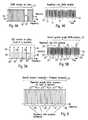
- Fig. 10shows a schematic example of a frequency domain representation of a frame structure or pattern 29 according to the present invention.
- the frame structure 29covers the entire transmission bandwidth 24 in the frequency direction and comprises at least two training patterns 30 adjacent to each other in the frequency direction, each carrying the identical sequence of pilot signals on respective frequency carriers and having the same length.
- the entire transmission bandwidth 24is sub-divided into four training patterns 30, but any other higher or lower number of training patterns might be suitable.
- a pilot mapping means 55is adapted to map the pilot signals onto the frequency carriers of each training pattern.
- a pseudo noise sequence or a CAZAC sequenceis used for the pilot signals, but any other sequence with good pseudo noise and/or correlation properties might be suitable.
- the pilot mapping means 55may be adapted to map a pilot signal onto every frequency carrier in the training patterns, as explained in relation to Fig. 4 .
- the pilot mapping means 55might be adapted to map a pilot signal onto every m-th frequency carrier (m being a natural number larger than 1) as for example explained in relation to Fig. 5 .
- the length or bandwidth 39 of every training pattern 30is the same as the bandwidth 38 to which the tuner of the receiving apparatus 63 can be tuned.
- the part of the transmission bandwidth to which the tuner of the receiving apparatus 63 can be tunedmay be larger than the length of a training pattern 30.
- the received pilotscan further (after transformation into the frequency domain in the transformation means 68) be used for a channel estimation for the frequency carriers in the frame in a channel estimation means 69, which provides a de-mapping means 70 with the necessary channel estimation information enabling a correct de-mapping of the data in the received data signals.
- the received pilotscan be used in the receiving apparatus 63 for a frequency offset calculation in a corresponding means which is not shown in Fig. 17 .
- the frame structure or pattern 29further comprises at least two signalling patterns 31 adjacent to each other in the frequency direction which follow the training patterns 30 in the time direction.
- Each signalling pattern 31has the same length and bandwidth as the respectively preceding training pattern 30, and the beginning and the end of each signalling pattern 31 in the frequency direction are identical to the beginning and the end of the respective (time wise) preceding training pattern 30, so that the frequency structure of the signalling patterns 31 is identical to the frequency structure of the training patterns 30.
- the signalling patterns 31are aligned to the training patterns 30.
- the transmitting apparatus 54 of the present invention shown in Fig. 16comprises a signalling data mapping means 57 which is adapted to map signalling data onto the frequency carriers of each signalling pattern 31.
- each signalling pattern 31comprises for example the location of the signalling pattern 31 within the frame.
- each signalling pattern 31 in each framehas and carries the identical signalling data, except the location of the respective signalling pattern in the frame, which is different in each signalling pattern 31 in a frame.
- the signalling dataare for example L1 signalling data which contain all physical layer information that is needed by the receiving apparatus 63 to decode received signals.
- any other suitable signalling datamay be comprised in the signalling patterns 31.
- the signalling patterns 31might for example comprise the location of the respective data segments 32, 33, 34, 35, 36 so that a receiving apparatus 63 knows where the wanted data segments are located so that the tuner of the receiving apparatus 63 can tune to the respective location in order to receive the wanted data segments.
- the receiving apparatus 63after the receiving means 65 with the tuner, comprises a transformation means 68 for transforming the received time domain signals into the frequency domain, where after the signalling data (after an optional reconstruction in a reconstruction means 71), are de-mapped in a de-mapping means 72 and then evaluated in an evaluation means 73.
- the evaluation means 73is adapted to extract the necessary and required signalling information from the received signalling data. If necessary, additional signalling patterns could be provided in the time direction immediately succeeding the signalling patterns 31.
- the frame structure or pattern 29further comprises at least two data segments extending over the entire frequency bandwidth 24 in the frequency direction and following the signalling patterns 31 in the time direction.
- the frame structure 29shows several data segments 32, 33, 34, 35, 36 and 37 with different lengths, i.e. a different number of respective frequency carriers onto which data are mapped.
- the frame structure 29further comprises additional data segments in succeeding time slots, whereby the additional data patterns respectively have the same length and number of frequency carriers as the respectively preceding data pattern.
- the data pattern 32', 32" and 32'"have the same length as the first data pattern 32.
- the data patterns 33', 33" and 33'''have the same length as the data segment 33.
- the additional data patternshave the same frequency dimension structure as the several data patterns 32, 33, 34, 35, 36 and 37 in the first time slot after the signalling patterns 31.
- the receiving apparatus 63for example tunes to a part 38 of the transmission bandwidth in order to receive the data pattern 35, all time wise succeeding data patterns 35', 35" and 35''' which have the same length as the data pattern 35 can be properly received.
- the flexible and variable data pattern structure of the frame structure or pattern 29 as suggested by the present inventioncan for example be implemented in the transmitting apparatus 54 of the present invention as shown in Fig. 16 by mapping of various different data streams, for example with different kinds of data and/or data from different sources, as visualized by the branches data 1, data 2 and data 3 in Fig. 16 .
- the respective dataare then mapped onto frequency carriers in respective data patterns by the respective data mapping means 58, 58' and 58''.
- at least some of the various data patternsmay have different lengths, i.e. different numbers of frequency carriers in case that the frequency carriers are equidistant and have the same bandwidth, respectively.
- the number of data patterns in the frequency directionmay be the same as the number of training patterns, wherein the length (or bandwidth) of each data patterns may be identical to the length of each training patterns and they may be aligned to each other (have the same frequency direction structure).
- each data patternmight have the same length and the number of the data patterns might be a multiple of the number of training patterns, while still having the same frequency structure and alignment. Thus for example, 2, 3, 4 or more data patterns would be aligned to each of the training patterns.
- the length of the data patternsneeds to be smaller or at maximum equal to the effective receiver bandwidth so that the data patterns can be received in the receiving apparatus 63.
- the transmitting apparatus 54may be adapted to change the data pattern structure, e.g. the length and/or the number of the data patterns dynamically.
- the structure of the data patternscould be fixed or permanent.
- the data patternscould advantageously comprise pilot signals mapped on some of the frequency carriers in order to enable a fine channel estimation on the receiving side.
- the pilot signalcould be scattered among the carriers with the data in a regular or an irregular pattern depending.
- the frequency carriers with the pilots from the pilot mapping means 55, the frequency carriers with the signalling data from the signalling mapping means 57 and the frequency carriers with the data from the various data mapping means 58, 58', 58"are then combined to a frame pattern or structure 29 according to the present invention in a frame forming means 59.
- the frame structure of the present inventioncould be fixed or permanent, i.e. the overall bandwidth as well as the extension of each frame in the time direction could be fixed and always the same.
- the frame structurecan also be flexible, i.e. the overall bandwidth and/or the extension of each frame in the time direction could be flexible and changed from time to time depending on the desired application.
- the number of time slots with data patternscould be flexibly changed.
- the changescould be signalled to a receiving apparatus in the signalling data of the signalling patterns.
- the part 38 to which the receiving apparatus 63 is tuneddoes not match with the frequency structure of the training patterns 30 and signalling patterns 31.
- the correlation means 67 of the receiving apparatus 63is still able to perform an auto-(or cross-)correlation.
- the receiving apparatus 63needs knowledge about the offset of the part 38 in relation to the frequency structure of the frame pattern 29 in order to be able to re-arrange the receive signalling carriers into the original signalling sequence of the signalling patterns 31 which is done in a reconstruction means 71. This is due to the fact that the signalling patterns 31 have the same length and frequency structure as the training patterns 30.
- the receiving apparatus 63may tune to an arbitrary frequency part of the overall transmission bandwidth.
- the training pattern 30could for example have a 8 MHz bandwidth.
- the receiving apparatus 63is able to receive an entire training pattern 30 in the original or re-ordered sequence as well as an entire signalling pattern 31 in the original or re-ordered sequence from the received training pattern 30.
- the receiving apparatus 63is able to perform a correlation in the correlation means 67 in order to obtain a time synchronisation, as well as perform a channel estimation (usually a coarse channel estimation) in a channel estimation means 69 and/or a frequency offset calculation after a transformation of the received time domain signals into the frequency domain in the transformation means 68.
- the evaluation means 73 of the receiving apparatus 63the received signalling data are evaluated, for example the location of the received signalling pattern in the frame is obtained so that the receiver can freely and flexibly tune to the respectively wanted frequency position, such as the part 38 is shown in Figure 10 .
- the receiving apparatus 63In the new tuning position, which will usually not necessarily match with the frequency structure of the training patterns 30 and the signalling patterns 31, the receiving apparatus 63 is still able to perform synchronisation, channel estimation and frequency offset calculation on the basis of the pilot signals of the training patterns 30 due to their cyclic nature.
- the received signalling signalsIn order to be able to properly evaluate the signalling data of the signalling patterns 31, the received signalling signals have to be re-ordered which is performed in a reconstructing means 71 as described.
- Fig. 11shows this reordering in a schematic example.
- the last part 31' of a previous signalling patternis received before the first part 31 " of a succeeding signalling pattern, where after the reconstructions means 71 places the part 31' after the part 31" in order to reconstruct the original sequence of the signalling data, where after the reordered signalling pattern is evaluated in the evaluation means 73 after a corresponding de-mapping of the signalling data from the frequency carriers in the de-mapping means 72. It is to be remembered that the content of each signalling pattern 31 is the same, so that this reordering is possible.
- a receiving apparatusdoes not provide a flat frequency response over the complete receiving bandwidth to which the receiver is tuned.
- a transmission systemusually faces increasing attenuation at the boarder of the receiving bandwidth window.
- Fig. 12shows a schematic representation of a typical filter shape example. It can be seen that the filter is not rectangular, so that e.g. instead of 8 MHz bandwidth, the receiving apparatus is only able to effectively receive 7.4 MHz bandwidth. The consequence is that the receiving apparatus 63 may not be able to perform the reordering of the signalling data as described in relation to Fig. 11 in case that the signalling patterns 31 have the same length and bandwidth as the receiving bandwidth of the receiving apparatus 63, so that some signals are lost and cannot be received at the border of the receiving bandwidth.
- the present inventionalternatively or additionally suggests to use signalling patterns 31a which have a reduced length as compared to the training patterns 30.
- the example shown in Fig. 13it is suggested to use signalling patterns 31a which have exactly half the length of a training pattern 30, but still the same frequency structure as the training patterns 30. In other words, respective two (i.e. pairs) of the half length signalling patterns 31a are matched and aligned with each one of the training patterns 30 as shown in Fig. 13 .
- each pair of signalling patterns 31awould have the identical signalling data including the location of the signalling patterns 31a in the respective frame.
- the signalling datawould be identical except the location information.
- additional half length signalling patterns 31bin the time slot succeeding the signalling patterns 31a and before the data patterns 32, 34, 35, 36 and 37.
- the additional signalling patterns 31bhave the same time and frequency arrangement/alignment as the signalling patterns 31a, but comprise additional and different signalling information as the signalling information contained in the signalling patterns 31a.
- the receiving apparatus 63will be able to receive the signalling patterns 31a and 31b completely and in the original sequence so that a reconstruction or reordering is not necessary.
- the reconstruction means 71 in the receiving apparatus 63can be omitted. It is also possible to only provide one time slot with half length signalling patterns 31a if all necessary signalling data can be transmitted in the half length and the additional signalling patterns 31b are not necessary. Alternatively, even more half length signalling patterns could be used in the succeeding time slot after the signalling patterns 31 b.
- the length (or bandwidth) of the training patterns, the data patterns and/or the signalling patternscould be adapted to, e.g. could be smaller than or at maximum equal to, the effective receiving bandwidth of the receiving apparatus 63, for example the output bandwidth of the receiving band pass filter, as described above.
- the training patterns, the signalling patterns and/or the data patterns of the frame structure described by the present inventioncould comprise additional guard bands, i.e. unused carriers at the beginning and/or the end of the respective pattern or frame.
- each training patterncould comprise a guard band at the beginning and the end of each pattern.
- the training pattern at position 39could comprise a guard band only at the beginning of the pattern, and the last training pattern in each frame could comprise a guard band only at the end of the pattern.
- the training pattern at position 39could comprise a guard band at the beginning as well as at the end of the pattern, and the last training pattern in each frame could comprise a guard band at the beginning as well as at end of the pattern.
- the length of the guard band comprised in some or all of the training patternscould for example be smaller or at maximum equal to the maximum frequency offset the receiving apparatus can cope with.
- the guard bandcould for example have a length of 250 to 500 kHz or any other suitable length.
- each of the guard bands comprised in the training patternscould be at least the length of the carriers which are not received in the receiving apparatus due to the filter characteristics as described in relation to Fig. 12 .
- the length of each of the guard bands comprised in the training patternscould be at least the length of each of the signalling pattern guard bands.
- each signalling patterncould comprise a guard band with unused carriers at the beginning and the end of each pattern.
- the length of each of the guard bands comprised in the signalling patternscould be at least the length of the carriers which are not received in the receiving apparatus due to the filter characteristics as described in relation to Fig. 12 , so that the length of the signalling data in each signalling pattern is equal to (or may be smaller than) the effective receiver bandwidth.
- each data patterncould comprise a guard band with unused carriers at the beginning and the end of each pattern.
- the length of the guard bandscould for example be the same as the length of the guard bands of the signalling patterns if the signalling patterns comprise guard bands.
- the data patterns 32, 32', 32", 32'''could comprise a guard band only at the beginning of the data pattern, and the last data patterns in each frame in the frequency direction, in the example of Figures 10 and 13 the data patterns 37, 37', 37", 37"' could comprise a guard band at the end of the data pattern.
- the length of the guard bands of the data carrierscould be the same as (or could be different from) the length of the guard bands of the signalling patterns.
- the transmitting apparatus 54could optionally comprise an error coding means 56 adapted to add some kind of error coding, redundancy, such as repetition coding, or the like to the signalling data which are mapped onto the frequency carriers of a signalling pattern by the signalling mapping means 57.
- the additional error codingwould enable the transmitting apparatus 54 to use signalling patterns 31 in the same length as the training patterns 30, as shown in Fig. 10 , since the receiving apparatus 63 is able, for example, by means of the reconstructing means 71, to perform some kind of error detection and/or correction in order to reconstruct the original signalling pattern.
- the present inventionfurther suggests to optimize the tuning position of the receiving apparatus 63.
- the receiveris tuned to a part 38 of the transmission bandwidth by centering the part 38 around the frequency bandwidth of the data patterns to be received.
- the receiving apparatus 63could be tuned so that the reception of the signalling pattern 31 is optimized by placing the part 38 so that a maximum part of a signalling pattern 31 is received while the wanted data pattern is still fully received.
- the present inventionsuggests that the length of the respective data patterns should not be different from the length of the respective preamble patterns 30 and signalling patterns 31 by more than a certain percentage for example 10%.
- Fig. 14An example for this solution can be found in Fig. 14 .
- the borders between the data patterns 42, 43, 44 and 45are (in the frequency direction) not deviating from the borders between preamble patterns 30 and the signalling patterns 31 by more than a certain percentage, such as (but not limited to) 10%. This small percentage can then be corrected by the above-mentioned additional error coding in the signalling patterns 31.
- Fig. 15shows a time domain representation of an example of frame 47 according to the present invention.
- the frequency domain frame patternis transformed into the time domain by a transformation means 60.
- An example of a resulting time domain frameis now shown in Fig. 15 .
- the frame 47comprises a number of shortened training symbols 48, resulting from a mapping of pilot signals only onto every m-th frequency carrier (m being a natural number larger or equal than 2) by a pilot mapping means 55, followed by a guard interval 49, a signalling symbol 50, a further guard interval 51 and a number of data symbols 52, which are respectively separated by guard intervals 53.
- the frame 47would comprise two signalling symbols separated by a guard interval.
- the guard intervalscould e.g. be cyclic extensions of the useful parts of the respective symbols.
- the synchronization reliabilitycould be generally enhanced by inverting the last training symbol, i.e. by inverting the phase of the last training symbol in respect to the preceding training symbols (which have all the same phase).
- the time domain framesare then forwarded to a transmission means 61 which processes the time domain signal depending on the used multi-carrier system, for example by up-converting the signal to the wanted transmission frequency.
- the transmission signalsare then transmitted via a transmission interface 62, which can be a wired interface or a wireless interface, such as an antenna or the like.
- the number of shortened training symbols 48 in frame 47is depending on the wanted implementation and the used transmission system. As a non-limiting example, the number of shortened training symbols 48 could be 8, which is a good compromise between correlation complexity and synchronization reliability.
- Fig. 15further shows that a respective number of frames could be combined to super frames.
- the number of frames per super framei.e. the length of each super frame in the time direction, could be fixed or could vary.
- the signalling data in the signalling patterns for each frame in a super frameare the same and if changes in the signalling data only occur from super frame to super frame.
- the modulation, coding, number of data patterns etc.would be the same in each frame of a super frame, but could then be different in the succeeding super frame.
- the length of the super frames in broadcast systemscould be longer since the signalling data might not change as often, and in interactive system the super frame length could be shorter since an optimization of the transmission and reception parameters could be done on the basis of feedback from the receiver to the transmitter.
- the elements and functionalities of the transmitting apparatus 54have been explained before. It has to be understood, that an actual implementation of a transmitting apparatus 54 will contain additional elements and functionalities necessary for the actual operation of the transmitting apparatus in the respective system. In Fig. 16 , only the elements and means necessary for the explanation and understanding of the present invention are shown. The same is true for the receiving apparatus 63, a block diagram of which is shown in Fig. 17. Fig. 17 only shows elements and functionalities necessary for the understanding of the present invention. Additional elements will be necessary for an actual operation of the receiving apparatus 63. It has to be further understood that the elements and functionalities of the transmitting apparatus 54 as well as the receiving apparatus 63 can be implemented in any kind of device, apparatus, system and so forth adapted to perform the functionalities described and claimed by the present invention.
- the present inventionis further directed to a frame structure (and a correspondingly adapted transmitting and receiving apparatus and method as described above), which, as an alternative to the above described embodiments, does have a number (two or more) data patterns in which at least one data pattern has a length which is different from the length of the other data pattern(s).
- This structure of data patterns with a variable lengthcan be combined either with a sequence of training patterns with identical lengths and contents as described above, or with a sequence of training patterns in which at least one training pattern has a length and/or a content different from the other training patterns, i.e. a variable training pattern length.
- the receiving apparatus 63will need some information about the varying data pattern length, which could be transmitted by means of a separate signalling data channel or by means of signalling data comprised in signalling data patterns comprised in the frame structure as described above.
- the first training pattern and the first signalling pattern in each framealways have the same length so that the receiving apparatus can always obtain the information about the varying data patterns by receiving the first training patterns and signalling patterns in every or the necessary frames.
- other implementationsmight be possible. Otherwise, the rest of the above description in relation to the training patterns, the data patterns and the signalling patterns as well as the possible implementations in the transmitting apparatus 54 and the receiving apparatus 63 is still applicable.
Landscapes
- Engineering & Computer Science (AREA)
- Signal Processing (AREA)
- Computer Networks & Wireless Communication (AREA)
- Multimedia (AREA)
- Power Engineering (AREA)
- Mobile Radio Communication Systems (AREA)
- Cable Transmission Systems, Equalization Of Radio And Reduction Of Echo (AREA)
- Circuits Of Receivers In General (AREA)
- Transmitters (AREA)
- Two-Way Televisions, Distribution Of Moving Picture Or The Like (AREA)
- Digital Transmission Methods That Use Modulated Carrier Waves (AREA)
- Time-Division Multiplex Systems (AREA)
Abstract
Description
- The present invention is directed to a new frame and training pattern structure for multi-carrier systems.
- The present invention is hereby mainly directed (but not limited) to broadcast systems, such as for example cable based or terrestrial digital broadcast systems, in which content data, signalling data, pilot signals and so forth are mapped on to a plurality of frequency carriers, which are then transmitted in a given overall or complete transmission bandwidth. The receiver typically tunes to a partial channel (part of the overall transmission bandwidth) out of the complete transmission bandwidth (sometimes called segmented reception) in order to receive only the content data which are necessary or wanted by the respective receiver. For example, in the ISDB-T standard, the overall channel bandwidth is hereby divided into 13 fixed segments of an equal length (equal number of frequency carriers).
EP 1 650 921 AUS 2007/0268975 A1 discloses different ways to configure preambles to support the transmission of data symbols in a wireless communication system.- The object of the present invention is therefore to provide a receiving apparatus and method, as well as a system and a method for transmitting and receiving signals in a multi-carrier system, which allow a flexible tuning to any required part of the transmission bandwidth.
- The above object is achieved by a receiving apparatus according to
claim 1, a receiving method according toclaim 11, as well as a system for transmitting and receiving signals according toclaim 21 and a method for transmitting and receiving signals according toclaim 22. - The present invention therefore suggests a multi-carrier system which uses a frame structure or frame pattern in the frequency domain as well as in the time domain. In the frequency domain, each frame comprises at least two identical training patterns (which could also be called preamble patterns), which respectively carry the identical pilot signals on frequency carriers and respectively have the same length (or bandwidth). After a conversion into the time domain, in the resulting time domain signal, each frame then comprises a respective preamble (or training) symbol as well as data symbols. Each frame pattern covers the entire or overall transmission bandwidth in the frequency direction, so that the overall transmission bandwidth is therefore equally divided by the respectively identical training patterns. The data patterns of each frame then follow the training patterns in time. The receiving apparatus can be freely and flexibly tuned to any wanted part of the transmission bandwidth, provided that the part of the transmission bandwidth to which the receiving apparatus can be tuned has at least the length of one of the training patterns. Hereby, the receiving apparatus is always able to receive the pilot signals of an entire training pattern, so that a correlation of the received pilot signals in order to provide a time synchronisation, i.e. in order to define a synchronisation point or to start of a next frame, and/or a frequency offset calculation and/or a channel estimation is/are possible in the receiving apparatus.
- Advantageously, an auto-correlation is performed on the basis of the pilot signals received in the selected part of the transmission bandwidth. Although the receiver can be flexibly tuned to any wanted part of the transmission bandwidth, it is always possible to receive the pilot signals of an entire training pattern due to the new frame structure suggested by the present invention. Even if the selected part of the transmission bandwidth to which the receiver is tuned does not completely and correctly match with one of the training patterns (in the frequency direction), the receiver will in such cases receive the last part of a (frequency wise) preceding training pattern and the first part of a (frequency wise) succeeding training pattern. Since each of the training patterns is identical, the receiver is able to perform an auto-correlation in order to obtain the wanted time synchronisation without any problems even without any reordering or other processing of the received pilot signals. Alternatively, in case that the receiving apparatus knows its (frequency dimension) offset from the training pattern structure in each frame, it may be able to re-arrange the received pilot signals in the original sequence of pilot signals, in which case a cross-correlation can be performed by comparing a stored version of the training pattern with the received (rearranged) version of the training pattern received in the selected part of the transmission bandwidth. In some applications, a cross-correlation may result in an even more accurate determination of the time synchronisation as compared to an auto-correlation.
- Further advantageously, in case that each frame comprises at least two signalling patterns (in addition to the training and the data patterns), whereby each signalling pattern comprises signalling data mapped onto frequency carriers, the receiver of the present invention is adapted to reconstruct the original signalling pattern from the received selected part of the transmission bandwidth. Each signalling pattern may hereby have the same length in the frequency dimension. For example, every signalling pattern in a frame may hereby have the identical signalling data mapped onto its frequency carriers. Alternatively, the signalling data of each signalling pattern in a frame may comprise the location of the signalling pattern in the frame, in which case every signalling pattern in a frame has the identical signalling data mapped onto its frequency carriers except the location information, which is different at least for some each signalling patterns in each frame. For example, in case that the part of the transmission bandwidth to which the receiver is tuned does not match with the signalling pattern structure (in the frequency dimension), the receiver might know its offset from the original signalling pattern and would therefore be able to rearrange the received signalling signals and to bring them into the original sequence or order so that all necessary signalling data can be correctly identified and further used. Alternatively, the receiver may comprise the possibility to perform an error detection and/or correction decoding on the received signalling signals in order to reconstruct the original signalling pattern. Hereby, the transmitted signalling patterns may comprise additional error coding, redundancies or the like enabling the receiver to reconstruct the original signalling pattern even if only a part of the signalling pattern can be received.
- Advantageously, the receiver is adapted to be tuned to and to receive a selected part of said transmission bandwidth so that an optimized receipt of a signalling pattern in the selected part of the transmission bandwidth is enabled. Particularly if the frequency dimension structure of the data patterns and the signalling patterns in a frame do not match, and if the selective part of the transmission bandwidth to be received in the receiver is larger (in frequency dimension) than the data pattern(s) to be received, it may be possible to optimize the tuning so that the best possible receipt of a signalling pattern is achieved, for example by adjusting the tuning so that the maximum part of one entire signalling pattern is received while still receiving the entire wanted data pattern(s).
- Generally, it may be advantageous to tune the receiver so that the selective part of the transmission bandwidth is received so that at least one data pattern to be received is centered in relation to the selective part of the transmission bandwidth.
- Further advantageously, the receiver can be tuned to receive a selective part of said transmission bandwidth on the basis of signalling information received in a signalling pattern of a previous frame.
- It has to be understood that the present invention can be applied to any kind of multi-carrier system in which a transmitting apparatus is adapted to transmit data in an entire transmission bandwidth and a receiving apparatus is adapted to selectively receive only a part of said entire transmission bandwidth. Non limiting examples for such systems may be existing or future uni-directional or bi-directional broadcast systems, such as wired or wireless (for example cable based, terrestrial etc.) digital video broadcast systems. The non limiting example for a multi-carrier system would be an orthogonal frequency division multiplex (OFDM) system, however, any other suitable system could be used in which data, pilot signals and the like are mapped on a plurality of frequency carriers. The frequency carriers may hereby be equidistant and respectively have the same length (bandwidth). However, the present invention may also be used in multi-carrier systems in which the frequency carriers are not equidistant and/or do not have the respectively same length. Further, it should be understood that the present invention is not limited to any kind of specific frequency range neither in the overall transmission bandwidth applied on the transmitting side nor on the selected part of the transmission bandwidth to which the receiving side is tuned. However, in some applications it might be advantageous to use a receiving bandwidth on the receiving side, i.e. a bandwidth for the part of the transmission bandwidth to which the receiver can be tuned, which corresponds to the bandwidth of receiving devices of existing (digital video broadcast or other) systems. A non limiting example for a receiver bandwidth may be 8 MHz, i.e. the receiving side can be tuned to any wanted 8 MHz bandwidth from the overall transmission bandwidth. Hereby, the overall transmission bandwidth could be a multiple of 8 MHz, for example 8 MHz, 16 MHz, 24 MHz, 32 MHz etc, so that the segmentation of the overall transmission bandwidth, i.e. length of each training pattern could be 8 MHz. However, other segmentations are possible, e.g. (but not limited to) a length of each training pattern of 6 MHz.
- Generally, in case of the non limiting example of 8 MHz for the receiver bandwidth, the length of each of the training patterns used in the frame structure of the present invention would be also 8 MHz (or less).
- The present invention is explained in more detail in the following description of preferred embodiments in relation to the enclosed drawings, in which
Fig. 1 shows a schematic diagram of an entire transmission bandwidth from which a selected part can be selectively and flexibly received by a receiver,Fig. 2 shows an example for a segmentation of the overall transmission bandwidth,Fig. 3 shows a schematic time domain representation of a frame structure according to the present invention,Fig. 4A shows a frequency domain example of a training pattern,Fig. 4B shows a time domain representation of the training pattern ofFig. 4A ,Fig. 5A shows a frequency domain representation of a further example of a training pattern,Fig. 5B shows a time domain representation of the training pattern ofFig. 5A ,Fig. 6 shows a schematic frequency domain representation of an overall transmission bandwidth with repetitive training patterns according to the present invention.Fig. 7 shows a simulation result of an auto-correlation of multi-carrier system in which the transmission bandwidth is equal to the reception bandwidth,Fig. 8 shows a simulation result for an auto-correlation in which the receiving bandwidth coincides with a training pattern according to the present invention,Fig. 9 shows a simulation result of an auto-correlation in case that the receiving bandwidth does not coincide with a training pattern according to the present invention,Fig. 10 shows a schematic example of a frame structure or pattern according to the present invention,Fig. 11 shows a part of the frame structure ofFig. 10 with an explanation of a reconstruction of a signalling pattern,Fig. 12 shows a schematic example of a receiver filter characteristic,Fig. 13 shows a further example of a frame structure of pattern according to the present invention,Fig. 14 shows a part of a further example of a frame structure or pattern according to the present invention,Fig. 15 schematically shows an example of a frame structure of the present invention in the time dimension,Fig. 16 shows a schematic block diagram of an example of a transmitting apparatus according to the present invention, andFig. 17 shows a schematic block diagram of an example of a receiving apparatus according to the present inventionFig. 1 shows a schematic representation of anentire transmission bandwidth 1, in which a transmitting apparatus according to the present invention, as for example the transmittingapparatus 54 schematically shown inFig. 16 , transmits signals in a multi-carrier system in line with the present invention.Fig. 1 further schematically shows a block diagram of a receivingapparatus 3 of the present invention, which is adapted to be tuned to and selectively receive a selectedpart 2 of thetransmission bandwidth 1. Hereby, the receivingapparatus 3 comprises atuner 4 which is adapted to be tuned to and selectively receive the wantedpart 2 of thetransmission bandwidth 1 as well as further processing means 5 which perform the further necessary processing of the received signals in line with the respective communication system, such as a demodulation, channel decoding and the like. A more elaborate example of a receiving apparatus according to the present invention is shown in the schematic block diagram ofFig. 17 , which shows a receivingapparatus 63 comprising a receivinginterface 64, which can for example be an antenna, an antenna pattern, a wired or cable-based receiving interface or any other suitable interface adapted to receive signals in the respective transmission system or communication system. The receivinginterface 64 of the receivingapparatus 63 is connected to a receiving means 65 which comprises a tuning means, such as the tuning means 4 shown inFig. 1 as well as further necessary processing elements depending on the respective transmission or communication system, such as down conversion means adapted to down convert the received signal to an intermediate frequency or the base band.- As stated above, the present invention enables a flexible and changing reception of a wanted
part 2 of thetransmission bandwidth 1 in a receiver by providing a specific and new frame structure for a multi-carrier system.Fig. 2 shows a schematic representation of anoverall transmission bandwidth 1, within which a transmittingapparatus 54 of the present invention is adapted to transmit data content, such as video data, audio data or any other kind of data, in different segments orparts parts apparatus 54 to transmit different kinds of data, data from different sources, data intended for different recipients and so forth. Theparts apparatus 63. Theparts 7, 8 and 10 have smaller bandwidths. The present invention now suggests to apply a frame structure or pattern to theentire transmission bandwidth 1 whereby each frame comprises at least two training patterns adjacent to each other in the frequency direction and a number of data patterns. Each training pattern of a frame will have the same length and the identical pilot signals. In other words, theoverall transmission bandwidth 1 is divided into equal parts for the training patterns, whereby the maximum bandwidth to which a receiver can be tuned, for example the bandwidth shown forparts Fig. 2 , has to be equal or larger than the length of each training pattern. Hereby, by properly receiving an entire training pattern, a receivingapparatus 63 according to the present invention can correctly synchronize to the transmittingapparatus 54 and tune to and receive the wanted data in a flexible and non limiting way. Additionally, a frequency offset calculation and/or a channel estimation is/are possible in the receivingapparatus 63 on the basis of such a received training pattern. It is further clear that the length of the various data parts in the transmission bandwidth cannot exceed the length (number of frequency carriers) of the training patterns in the respective frame as will be explained in more detail further below. Fig. 3 shows a schematic representation of a time domain structure offrames frame more signalling symbols 13, 13'andseveral data symbols 14, 14'. Hereby, in the time domain, the preamble symbols or training symbols are preceding the signalling symbols which are preceding the data symbols. Eachframe frame apparatus 63 to perform time synchronisation and eventually additional tasks, such as channel estimation and/or frequency offset calculation. The signallingsymbols 13, 13', contain signalling information, for example all physical layer information that is needed by the receivingapparatus 63 to decode the received signals, such as but not limited to L1 signalling data. The signalling data may for example comprise the allocation of data content to the various data patterns, i.e. for example which services, data streams, modulation, error correction settings etc. are located on which frequency carriers, so that the receivingapparatus 63 can obtain information to which part of the entire transmission bandwidth it shall be tuned. Further, the signalling symbols may contain signalling data indicating the offset of the respective data pattern from the preamble or training pattern and/or the signalling pattern so that the receivingapparatus 63 may optimize the tuning to the wanted part of the transmission frequency in a way that the receipt of the training patterns and/or the signalling patterns is optimized. The use of the frame structure according to the present invention has the further advantage that by dividing the data stream into logical blocks, changes of the frame structure can be signalled from frame to frame, whereby a preceding frame signals the changed frame structure of the or one of the succeeding frames. For example, the frame structure allows a seamless change of modulation parameters without creating errors.Figures 4A, 4B, 5A and 5B show non limiting examples of preamble structures which could be used in the present invention. It has to be understood, however, that other possible preamble structures could also be used.Fig. 4A shows a frequency domain representation of a preamble ortraining pattern 15 in which a plurality of frequency carriers 16 (in the shown example 2048 carriers), respectively carry a pilot signal. In other words, all frequency carriers of thetraining pattern 15 carry a pilot signal.Fig. 4B shows the training pattern ofFig. 4A after the transformation in the time domain. The time domain training symbol comprises a plurality of time domain samples 17 (in the shown example 2048 samples) in a single repetition. In other words, the time domain training symbol does not have any repetitions in the time domain samples.Fig. 5A shows a further non limiting example of a frequency domain preamble pattern 18, comprising a plurality of frequency carriers (in the shown example 512 carriers). In the shown example, only every fourth sub-carrier carries apilot signal 19, allother sub-carriers 20 do not carry pilot signals. After transformation into the time domain, the time domain preamble or thetraining symbol 21 shown inFig. 5B shows fourrepetitions 22, eachrepetition 22 having the identical samples 23 (same value and number). In the shown example, the time domain training symbol has a length of 2048 time samples and eachrepetition 22 comprises 512 samples. The general rule is that the number of repetitions in the time domain corresponds to the repetition rate of the pilot signals in the frequency domain. In case that the distance of the pilot signals in the frequency domain is higher, the number of repetitions in the time domain increases. The repetitions in the time domain preamble or training symbol are sometimes called 'shortened` training symbols. In the example ofFig. 5B , the time domain symbol thus comprises four shortened training symbols. In some applications it may be advantageous to use pseudo noise pilot signal sequences in order to obtain pseudo noise like signal patterns in the time domain. Also, a so called CAZAC (constant amplitude zero auto correlation) sequence could be used for the pilot signals, or any other suitable sequence resulting in pseudo noise like signal patterns and having good correlation properties both in the frequency as well as in the time domain. Such sequences allow a time synchronisation in a receivingapparatus 63 of the present invention. In addition hereto, such sequences allow a reliable channel estimation in the receivingapparatus 63 in case that the Nyquist criterion is fulfilled in the frequency dimension. Further, such sequences allow a frequency offset calculation and/or a channel estimation in the receivingapparatus 63.- As mentioned above, the present invention suggests a frequency domain frame structure or frame pattern for the entire transmission bandwidth of the transmitting
apparatus 54, in which identical training patterns are repeated over the entire transmission bandwidth, i.e. immediately adjacent to each other in the frequency direction.Fig. 6 visualizes schematically such a sequence of identical andadjacent training patterns entire transmission bandwidth 24. In other words, the same sequence of pilot signals is mapped onto the frequency carrier of eachtraining pattern Fig. 6 , theoverall transmission bandwidth 24 is equally divided into thetraining patterns training patterns apparatus 63 of the present invention can be tuned in order to receive signals, in order to ensure that the receivingapparatus 63 is always able to receive an entire training pattern for synchronisation (and channel estimation, and /or frequency offset calculation). - The present invention therefore enables a receiving
apparatus 63 to be tuned to any position within theoverall channel bandwidth 24 in a very flexible manner while still being able to perform a reliable synchronisation by correlating the received pilot signals for example in a correlation means 67 of the transmittingapparatus 63 as shown inFig.17 . Again, the invention suggests to divide the entiretransmission frequency bandwidth 24 into adjacent sub-blocks or segments each having a training pattern containing a repetition of the identical pilot signal sequence and thus having the same length. The length of each of the training pattern thus corresponds advantageously to the bandwidth to which the receivingapparatus 63 can be tuned. For example, as shown inFig. 17 , the receivingapparatus 63 comprises a receivinginterface 64, such as an antenna, a wired receiving interface or the like, to which signals are received in a receiving means 65, which comprises a tuner. If the receivingapparatus 63 is tuned to a part of the transmission bandwidth which matches or coincides to one of the training patterns, the pilot signal sequence is received in the original order. If the receivingapparatus 63 is tuned to an arbitrary part of the transmission bandwidth or for example between two training patterns, still all pilot signals of the training pattern are received, however, not in the original sequence. However, due to the cyclic behaviour of the pilot sequence sequences, very good correlation properties are still present particularly if pseudo noise sequences are used for the pilot signals in each training pattern and the correlation means 67 of the receivingapparatus 63 of the present invention still delivers good results when performing an auto-correlation i.e. a correlation of the received pilot signals with themselves. Specifically, in wired systems, such as cable systems, auto-correlation is expected to deliver good results because of the high signal to noise ratio. Also, such sequences enable a frequency offset calculation and/or a channel estimation in the receivingapparatus 63. Fig. 7 shows an example of a simulation result for 64 sample pseudo noise sequence for a multi-carrier system without segmentation of the training pattern, i.e. in which the transmission bandwidth is identical to the receiving bandwidth. The correlation peak is clearly visible.Fig. 8 shows a further example of a simulation result for a system according to the present invention, in which the entire transmission bandwidth comprises identical training patterns and the receiver is tuned to a part of the transmission bandwidth. In the simulation shown inFig. 8 , the receiver was tuned and identically matched to the first segment, i.e. the first training pattern of the entire transmission bandwidth. In other words, the simulation shows an auto-correlation result for the situation in which the receiver receives the pilot signals of a training pattern in the original sequence. Again, the correlation peak is clearly visible.Fig. 9 now shows a simulation result for the system ofFig. 8 , whereby the receiver was tuned to a position between two training patterns so that the receiver did not receive the pilot signals in the original sequence, but received the last part of a preceding training pattern before the first part of the succeeding training pattern. However, due to the cyclic behaviour of the pilot sequences and the training patterns, it is still possible to obtain an auto-correlation peak, which is shown inFig. 9 .- In case that the receiving
apparatus 63 knows its tuning position, i.e. knows the offset from the start of a frame or from the respective start of each training pattern, an optionally provided rearranging means 66 could rearrange the received pilot signals into the original sequence and to perform a cross-correlation on the basis of a comparison with a stored version of the expected training pattern in order to obtain a cross-correlation result. Such a cross-correlation result will normally have a better quality then an auto-correlation result since it is less effected by noise. Thus, for systems with low signal to noise ratios, cross correlation would be the better choice. Fig. 10 shows a schematic example of a frequency domain representation of a frame structure orpattern 29 according to the present invention. Theframe structure 29 covers theentire transmission bandwidth 24 in the frequency direction and comprises at least twotraining patterns 30 adjacent to each other in the frequency direction, each carrying the identical sequence of pilot signals on respective frequency carriers and having the same length. In the example shown inFig. 4 , theentire transmission bandwidth 24 is sub-divided into fourtraining patterns 30, but any other higher or lower number of training patterns might be suitable. In the transmittingapparatus 54 of the present invention as shown inFig. 16 , a pilot mapping means 55 is adapted to map the pilot signals onto the frequency carriers of each training pattern. Advantageously, a pseudo noise sequence or a CAZAC sequence is used for the pilot signals, but any other sequence with good pseudo noise and/or correlation properties might be suitable. Also, the pilot mapping means 55 may be adapted to map a pilot signal onto every frequency carrier in the training patterns, as explained in relation toFig. 4 . Alternatively, the pilot mapping means 55 might be adapted to map a pilot signal onto every m-th frequency carrier (m being a natural number larger than 1) as for example explained in relation toFig. 5 . The length orbandwidth 39 of everytraining pattern 30 is the same as thebandwidth 38 to which the tuner of the receivingapparatus 63 can be tuned. However, the part of the transmission bandwidth to which the tuner of the receivingapparatus 63 can be tuned, may be larger than the length of atraining pattern 30. Besides for the correlation performed in the correlation means 67 in the receivingapparatus 63, the received pilots can further (after transformation into the frequency domain in the transformation means 68) be used for a channel estimation for the frequency carriers in the frame in a channel estimation means 69, which provides a de-mapping means 70 with the necessary channel estimation information enabling a correct de-mapping of the data in the received data signals. Also, the received pilots can be used in the receivingapparatus 63 for a frequency offset calculation in a corresponding means which is not shown inFig. 17 .- The frame structure or
pattern 29 further comprises at least two signallingpatterns 31 adjacent to each other in the frequency direction which follow thetraining patterns 30 in the time direction. Eachsignalling pattern 31 has the same length and bandwidth as the respectively precedingtraining pattern 30, and the beginning and the end of eachsignalling pattern 31 in the frequency direction are identical to the beginning and the end of the respective (time wise) precedingtraining pattern 30, so that the frequency structure of the signallingpatterns 31 is identical to the frequency structure of thetraining patterns 30. In other words, the signallingpatterns 31 are aligned to thetraining patterns 30. The transmittingapparatus 54 of the present invention shown inFig. 16 comprises a signalling data mapping means 57 which is adapted to map signalling data onto the frequency carriers of eachsignalling pattern 31. Hereby, each signallingpattern 31 comprises for example the location of thesignalling pattern 31 within the frame. For example eachsignalling pattern 31 in each frame has and carries the identical signalling data, except the location of the respective signalling pattern in the frame, which is different in eachsignalling pattern 31 in a frame. The signalling data are for example L1 signalling data which contain all physical layer information that is needed by the receivingapparatus 63 to decode received signals. However, any other suitable signalling data may be comprised in the signallingpatterns 31. The signallingpatterns 31 might for example comprise the location of therespective data segments apparatus 63 knows where the wanted data segments are located so that the tuner of the receivingapparatus 63 can tune to the respective location in order to receive the wanted data segments. As shown inFig. 17 , the receivingapparatus 63, after the receiving means 65 with the tuner, comprises a transformation means 68 for transforming the received time domain signals into the frequency domain, where after the signalling data (after an optional reconstruction in a reconstruction means 71), are de-mapped in a de-mapping means 72 and then evaluated in an evaluation means 73. The evaluation means 73 is adapted to extract the necessary and required signalling information from the received signalling data. If necessary, additional signalling patterns could be provided in the time direction immediately succeeding the signallingpatterns 31. - The frame structure or
pattern 29 further comprises at least two data segments extending over theentire frequency bandwidth 24 in the frequency direction and following the signallingpatterns 31 in the time direction. In the time slot immediately following the time slot in which the signallingpatterns 31 are located, theframe structure 29 showsseveral data segments frame structure 29 further comprises additional data segments in succeeding time slots, whereby the additional data patterns respectively have the same length and number of frequency carriers as the respectively preceding data pattern. For example, thedata pattern 32', 32" and 32'" have the same length as thefirst data pattern 32. Thedata patterns 33', 33" and 33''' have the same length as thedata segment 33. In other words, the additional data patterns have the same frequency dimension structure as theseveral data patterns patterns 31. Thus, if the receivingapparatus 63 for example tunes to apart 38 of the transmission bandwidth in order to receive thedata pattern 35, all time wise succeedingdata patterns 35', 35" and 35''' which have the same length as thedata pattern 35 can be properly received. - The flexible and variable data pattern structure of the frame structure or
pattern 29 as suggested by the present invention can for example be implemented in the transmittingapparatus 54 of the present invention as shown inFig. 16 by mapping of various different data streams, for example with different kinds of data and/or data from different sources, as visualized by thebranches data 1,data 2 anddata 3 inFig. 16 . The respective data are then mapped onto frequency carriers in respective data patterns by the respective data mapping means 58, 58' and 58''. As stated, at least some of the various data patterns may have different lengths, i.e. different numbers of frequency carriers in case that the frequency carriers are equidistant and have the same bandwidth, respectively. Alternatively, the number of data patterns in the frequency direction may be the same as the number of training patterns, wherein the length (or bandwidth) of each data patterns may be identical to the length of each training patterns and they may be aligned to each other (have the same frequency direction structure). Alternatively, each data pattern might have the same length and the number of the data patterns might be a multiple of the number of training patterns, while still having the same frequency structure and alignment. Thus for example, 2, 3, 4 or more data patterns would be aligned to each of the training patterns. Generally, the length of the data patterns needs to be smaller or at maximum equal to the effective receiver bandwidth so that the data patterns can be received in the receivingapparatus 63. Further, the transmittingapparatus 54 may be adapted to change the data pattern structure, e.g. the length and/or the number of the data patterns dynamically. Alternatively, the structure of the data patterns could be fixed or permanent. - Further, it is to be noted that the data patterns could advantageously comprise pilot signals mapped on some of the frequency carriers in order to enable a fine channel estimation on the receiving side. Hereby, the pilot signal could be scattered among the carriers with the data in a regular or an irregular pattern depending.
- In the transmitting
apparatus 54, the frequency carriers with the pilots from the pilot mapping means 55, the frequency carriers with the signalling data from the signalling mapping means 57 and the frequency carriers with the data from the various data mapping means 58, 58', 58" are then combined to a frame pattern orstructure 29 according to the present invention in aframe forming means 59. - Generally, the frame structure of the present invention could be fixed or permanent, i.e. the overall bandwidth as well as the extension of each frame in the time direction could be fixed and always the same. Alternatively, the frame structure can also be flexible, i.e. the overall bandwidth and/or the extension of each frame in the time direction could be flexible and changed from time to time depending on the desired application. For example, the number of time slots with data patterns could be flexibly changed. Hereby, the changes could be signalled to a receiving apparatus in the signalling data of the signalling patterns.
- It can be seen in
Figure 10 , that thepart 38 to which the receivingapparatus 63 is tuned, does not match with the frequency structure of thetraining patterns 30 andsignalling patterns 31. However, is explained above, due to the cyclic nature of the pilot signal sequences in thetraining patterns 30, the correlation means 67 of the receivingapparatus 63 is still able to perform an auto-(or cross-)correlation. Further, in this situation shown inFigure 10 , the receivingapparatus 63 needs knowledge about the offset of thepart 38 in relation to the frequency structure of theframe pattern 29 in order to be able to re-arrange the receive signalling carriers into the original signalling sequence of the signallingpatterns 31 which is done in a reconstruction means 71. This is due to the fact that the signallingpatterns 31 have the same length and frequency structure as thetraining patterns 30. - During the start-up phase or initialization phase of the receiving
apparatus 63, the receivingapparatus 63 may tune to an arbitrary frequency part of the overall transmission bandwidth. In the non-limiting example of a cable broadcast system, thetraining pattern 30 could for example have a 8 MHz bandwidth. Thus, during the start-up phase, the receivingapparatus 63 is able to receive anentire training pattern 30 in the original or re-ordered sequence as well as anentire signalling pattern 31 in the original or re-ordered sequence from the receivedtraining pattern 30. The receivingapparatus 63 is able to perform a correlation in the correlation means 67 in order to obtain a time synchronisation, as well as perform a channel estimation (usually a coarse channel estimation) in a channel estimation means 69 and/or a frequency offset calculation after a transformation of the received time domain signals into the frequency domain in the transformation means 68. In the evaluation means 73 of the receivingapparatus 63, the received signalling data are evaluated, for example the location of the received signalling pattern in the frame is obtained so that the receiver can freely and flexibly tune to the respectively wanted frequency position, such as thepart 38 is shown inFigure 10 . In the new tuning position, which will usually not necessarily match with the frequency structure of thetraining patterns 30 and the signallingpatterns 31, the receivingapparatus 63 is still able to perform synchronisation, channel estimation and frequency offset calculation on the basis of the pilot signals of thetraining patterns 30 due to their cyclic nature. However, in order to be able to properly evaluate the signalling data of the signallingpatterns 31, the received signalling signals have to be re-ordered which is performed in a reconstructingmeans 71 as described.Fig. 11 shows this reordering in a schematic example. The last part 31' of a previous signalling pattern is received before thefirst part 31 " of a succeeding signalling pattern, where after the reconstructions means 71 places the part 31' after thepart 31" in order to reconstruct the original sequence of the signalling data, where after the reordered signalling pattern is evaluated in the evaluation means 73 after a corresponding de-mapping of the signalling data from the frequency carriers in the de-mapping means 72. It is to be remembered that the content of eachsignalling pattern 31 is the same, so that this reordering is possible. - Often, a receiving apparatus does not provide a flat frequency response over the complete receiving bandwidth to which the receiver is tuned. In addition, a transmission system usually faces increasing attenuation at the boarder of the receiving bandwidth window.
Fig. 12 shows a schematic representation of a typical filter shape example. It can be seen that the filter is not rectangular, so that e.g. instead of 8 MHz bandwidth, the receiving apparatus is only able to effectively receive 7.4 MHz bandwidth. The consequence is that the receivingapparatus 63 may not be able to perform the reordering of the signalling data as described in relation toFig. 11 in case that the signallingpatterns 31 have the same length and bandwidth as the receiving bandwidth of the receivingapparatus 63, so that some signals are lost and cannot be received at the border of the receiving bandwidth. In order to overcome this problem, and other problems and in order to ensure that the receivingapparatus 63 is always able to receive one complete signalling patterns in the original sequence and does not have to reorder or rearrange the received signalling signals, the present invention alternatively or additionally suggests to usesignalling patterns 31a which have a reduced length as compared to thetraining patterns 30. The example shown inFig. 13 , it is suggested to usesignalling patterns 31a which have exactly half the length of atraining pattern 30, but still the same frequency structure as thetraining patterns 30. In other words, respective two (i.e. pairs) of the halflength signalling patterns 31a are matched and aligned with each one of thetraining patterns 30 as shown inFig. 13 . Hereby, each pair of signallingpatterns 31a would have the identical signalling data including the location of the signallingpatterns 31a in the respective frame. However, in relation to the other pairs of signalling patterns, in these other pairs, since they have a respective different location within the frame, the signalling data would be identical except the location information. Hereby, in order to ensure that the same amount of signalling data as before can be transmitted, it might be necessary to add additional halflength signalling patterns 31b in the time slot succeeding the signallingpatterns 31a and before thedata patterns additional signalling patterns 31b have the same time and frequency arrangement/alignment as the signallingpatterns 31a, but comprise additional and different signalling information as the signalling information contained in thesignalling patterns 31a. In this way, the receivingapparatus 63 will be able to receive thesignalling patterns apparatus 63 can be omitted. It is also possible to only provide one time slot with halflength signalling patterns 31a if all necessary signalling data can be transmitted in the half length and theadditional signalling patterns 31b are not necessary. Alternatively, even more half length signalling patterns could be used in the succeeding time slot after the signallingpatterns 31 b. - It should be generally (for all embodiments of the present invention) noted that the length (or bandwidth) of the training patterns, the data patterns and/or the signalling patterns could be adapted to, e.g. could be smaller than or at maximum equal to, the effective receiving bandwidth of the receiving
apparatus 63, for example the output bandwidth of the receiving band pass filter, as described above. - Further, it should be generally noted that the training patterns, the signalling patterns and/or the data patterns of the frame structure described by the present invention could comprise additional guard bands, i.e. unused carriers at the beginning and/or the end of the respective pattern or frame. For example, each training pattern could comprise a guard band at the beginning and the end of each pattern. Alternatively, in some applications it might be advantageous if only the first training pattern in each frame, in the example of
Figure 10 the training pattern atposition 39, could comprise a guard band only at the beginning of the pattern, and the last training pattern in each frame could comprise a guard band only at the end of the pattern. Alternatively, in some applications only the first training pattern in each frame, in the example ofFigures 10 the training pattern atposition 39, could comprise a guard band at the beginning as well as at the end of the pattern, and the last training pattern in each frame could comprise a guard band at the beginning as well as at end of the pattern. The length of the guard band comprised in some or all of the training patterns could for example be smaller or at maximum equal to the maximum frequency offset the receiving apparatus can cope with. In the mentioned example of a bandwidth of 8MHz for each training pattern, the guard band could for example have a length of 250 to 500 kHz or any other suitable length. Also, the length of each of the guard bands comprised in the training patterns could be at least the length of the carriers which are not received in the receiving apparatus due to the filter characteristics as described in relation toFig. 12 . Also, in case that the signalling patterns have guard bands, the length of each of the guard bands comprised in the training patterns could be at least the length of each of the signalling pattern guard bands.
Additionally or alternatively, each signalling pattern could comprise a guard band with unused carriers at the beginning and the end of each pattern. Hereby, the length of each of the guard bands comprised in the signalling patterns could be at least the length of the carriers which are not received in the receiving apparatus due to the filter characteristics as described in relation toFig. 12 , so that the length of the signalling data in each signalling pattern is equal to (or may be smaller than) the effective receiver bandwidth. - Additionally or alternatively, each data pattern could comprise a guard band with unused carriers at the beginning and the end of each pattern. Hereby, the length of the guard bands could for example be the same as the length of the guard bands of the signalling patterns if the signalling patterns comprise guard bands. Alternatively, in some applications only the respective first data patterns in each frame in the frequency direction, in the example of
Figures 10 and13 thedata patterns Figures 10 and13 thedata patterns - Alternatively or additionally, in order to overcome the problem that parts of the signalling
patterns 31 may not be receivable in the receivingapparatus 63, the transmittingapparatus 54 could optionally comprise an error coding means 56 adapted to add some kind of error coding, redundancy, such as repetition coding, or the like to the signalling data which are mapped onto the frequency carriers of a signalling pattern by the signalling mapping means 57. The additional error coding would enable the transmittingapparatus 54 to usesignalling patterns 31 in the same length as thetraining patterns 30, as shown inFig. 10 , since the receivingapparatus 63 is able, for example, by means of the reconstructingmeans 71, to perform some kind of error detection and/or correction in order to reconstruct the original signalling pattern. - In order to ensure a even better reception of the signalling patterns and the receiving
apparatus 63, the present invention further suggests to optimize the tuning position of the receivingapparatus 63. In the examples shown inFig. 10 and13 , the receiver is tuned to apart 38 of the transmission bandwidth by centering thepart 38 around the frequency bandwidth of the data patterns to be received. Alternatively, the receivingapparatus 63 could be tuned so that the reception of thesignalling pattern 31 is optimized by placing thepart 38 so that a maximum part of asignalling pattern 31 is received while the wanted data pattern is still fully received. Alternatively, the present invention suggests that the length of the respective data patterns should not be different from the length of therespective preamble patterns 30 andsignalling patterns 31 by more than a certain percentage for example 10%. An example for this solution can be found inFig. 14 . The borders between thedata patterns preamble patterns 30 and the signallingpatterns 31 by more than a certain percentage, such as (but not limited to) 10%. This small percentage can then be corrected by the above-mentioned additional error coding in the signallingpatterns 31. Fig. 15 shows a time domain representation of an example offrame 47 according to the present invention. In the transmittingapparatus 54, after the frame pattern or structure was generated in theframe forming means 59, the frequency domain frame pattern is transformed into the time domain by a transformation means 60. An example of a resulting time domain frame is now shown inFig. 15 . Theframe 47 comprises a number of shortenedtraining symbols 48, resulting from a mapping of pilot signals only onto every m-th frequency carrier (m being a natural number larger or equal than 2) by a pilot mapping means 55, followed by aguard interval 49, asignalling symbol 50, afurther guard interval 51 and a number ofdata symbols 52, which are respectively separated byguard intervals 53. In case of the presence of respective two signallingpatterns Fig. 13 , theframe 47 would comprise two signalling symbols separated by a guard interval. The guard intervals could e.g. be cyclic extensions of the useful parts of the respective symbols. The synchronization reliability could be generally enhanced by inverting the last training symbol, i.e. by inverting the phase of the last training symbol in respect to the preceding training symbols (which have all the same phase). The time domain frames are then forwarded to a transmission means 61 which processes the time domain signal depending on the used multi-carrier system, for example by up-converting the signal to the wanted transmission frequency. The transmission signals are then transmitted via atransmission interface 62, which can be a wired interface or a wireless interface, such as an antenna or the like.- The number of shortened
training symbols 48 inframe 47 is depending on the wanted implementation and the used transmission system. As a non-limiting example, the number of shortenedtraining symbols 48 could be 8, which is a good compromise between correlation complexity and synchronization reliability. Fig. 15 further shows that a respective number of frames could be combined to super frames. The number of frames per super frame, i.e. the length of each super frame in the time direction, could be fixed or could vary. Hereby, there might be a maximum length up to which the super frames could be set dynamically. Further, it might be advantageous if the signalling data in the signalling patterns for each frame in a super frame are the same and if changes in the signalling data only occur from super frame to super frame. In other words, the modulation, coding, number of data patterns etc. would be the same in each frame of a super frame, but could then be different in the succeeding super frame. For example, the length of the super frames in broadcast systems could be longer since the signalling data might not change as often, and in interactive system the super frame length could be shorter since an optimization of the transmission and reception parameters could be done on the basis of feedback from the receiver to the transmitter.- The elements and functionalities of the transmitting
apparatus 54, a block diagram of which is shown inFig. 16 , have been explained before. It has to be understood, that an actual implementation of a transmittingapparatus 54 will contain additional elements and functionalities necessary for the actual operation of the transmitting apparatus in the respective system. InFig. 16 , only the elements and means necessary for the explanation and understanding of the present invention are shown. The same is true for the receivingapparatus 63, a block diagram of which is shown inFig. 17. Fig. 17 only shows elements and functionalities necessary for the understanding of the present invention. Additional elements will be necessary for an actual operation of the receivingapparatus 63. It has to be further understood that the elements and functionalities of the transmittingapparatus 54 as well as the receivingapparatus 63 can be implemented in any kind of device, apparatus, system and so forth adapted to perform the functionalities described and claimed by the present invention. - The present invention is further directed to a frame structure (and a correspondingly adapted transmitting and receiving apparatus and method as described above), which, as an alternative to the above described embodiments, does have a number (two or more) data patterns in which at least one data pattern has a length which is different from the length of the other data pattern(s). This structure of data patterns with a variable length can be combined either with a sequence of training patterns with identical lengths and contents as described above, or with a sequence of training patterns in which at least one training pattern has a length and/or a content different from the other training patterns, i.e. a variable training pattern length. In both cases, the receiving
apparatus 63 will need some information about the varying data pattern length, which could be transmitted by means of a separate signalling data channel or by means of signalling data comprised in signalling data patterns comprised in the frame structure as described above. In the later case, it might be a possible implementation if the first training pattern and the first signalling pattern in each frame always have the same length so that the receiving apparatus can always obtain the information about the varying data patterns by receiving the first training patterns and signalling patterns in every or the necessary frames. Of course, other implementations might be possible. Otherwise, the rest of the above description in relation to the training patterns, the data patterns and the signalling patterns as well as the possible implementations in the transmittingapparatus 54 and the receivingapparatus 63 is still applicable.
Claims (22)
- Receiving apparatus (63) for receiving signals in a multi carrier system on the basis of a frame structure in a transmission bandwidth, each frame comprising at least two preamble patterns adjacent to each other in the frequency direction each with the same sequence of pilot signals mapped on frequency carriers and at least two data patterns following the at least two preamble patterns in the time direction in a time slot succeeding the time slot in which the at least two preamble patterns are located, wherein each of the at least two data patterns in a frame is respectively followed by further data patterns in succeeding time slots in the time direction, wherein all data patterns following each other in the time direction have the same frequency direction structure, said at least two data patterns and said further data patterns having data mapped on frequency carriers, each of said at least two preamble patterns having the same length, each of the at least two preamble patterns, the at least two data patterns and the further data patterns comprising a plurality of frequency carriers, wherein the length of each of the at least two preamble patterns is equal to or smaller than the effective receiving bandwidth of the receiving apparatus,
said receiving apparatus (63) comprising
receiving means (65) adapted to be tuned to and to receive a selected part of said transmission bandwidth, said selected part of said transmission bandwidth having at least the length of one of said preamble patterns and covering at least one data pattern to be received, and
correlation means (67) adapted to perform a correlation on the basis of the pilot signals received in said selected part of said transmission bandwidth. - Receiving apparatus (63) according to claim 1,
wherein said correlation means (67) is adapted to perform an auto-correlation on the basis of the pilot signals received in said selected part of said transmission bandwidth. - Receiving apparatus (63) according to claim 1,
wherein said correlation means (67) is adapted to perform a cross-correlation on the basis of a comparison between a stored version of a preamble pattern and a received version of the preamble pattern received in said selected part of said transmission bandwidth. - Receiving apparatus (63) according to claim 3,
comprising pilot rearranging means (66) adapted to rearrange said received pilot signals into the original sequence in case that the selected part of said transmission bandwidth to which the receiving means (65) is tuned does not match with the preamble pattern structure. - Receiving apparatus (63) according to one of the claims 1 to 4,
wherein each frame comprises at least two signalling patterns, each signalling pattern comprising the same signalling data mapped onto frequency carriers, said receiving apparatus (63) comprising a reconstructing means (71) adapted to reconstruct the original signalling pattern from said received selected part of said transmission bandwidth. - Receiving apparatus (63) according to claim 5,
wherein said reconstructing means (71) is adapted to rearrange said received signalling signals into the original signalling pattern in case that the selected part of said transmission bandwidth to which the receiving means is tuned does not match with the signalling pattern structure. - Receiving apparatus (63) according to claim 5,
wherein said reconstructing means (71) is adapted to perform an error correction decoding on said received signalling signals in order to reconstruct the original signalling pattern. - Receiving apparatus (63) according to one of the claims 5 to 7,
wherein said receiving means (65) is adapted to be tuned to and to receive a selected part of said transmission bandwidth so that an optimized receipt of a signalling pattern in the selected part of said transmission bandwidth to be received is enabled. - Receiving apparatus (63) according to one of the claims 1 to 7,
wherein said receiving means (65) is adapted to be tuned to and to receive a selected part of said transmission bandwidth so that said at least one data pattern to be received is centred in relation to the selected part of said transmission bandwidth to be received. - Receiving apparatus (63) according to one of the claims 1 to 9,
wherein said receiving means (65) is adapted to be tuned to and to receive a selected part of said transmission bandwidth on the basis of signalling information received in a signalling pattern of a previous frame. - Receiving method for receiving signals transmitted in a multi carrier system on the basis of a frame structure in a transmission bandwidth, each frame comprising at least two preamble patterns adjacent to each other in the frequency direction each with the same sequence of pilot signals mapped on frequency carriers and at least two data patterns following the at least two preamble patterns in the time direction in a time slot succeeding the time slot in which the at least two preamble patterns are located, wherein each of the at least two data patterns in a frame is respectively followed by further data patterns in succeeding time slots in the time direction, wherein all data patterns following each other in the time direction have the same frequency direction structure, said at least two data patterns and said further data patterns having data mapped on frequency carriers, each of said at least two preamble patterns having the same length, each of the at least two preamble patterns, the at least two data patterns and the further data patterns comprising a plurality of frequency carriers, wherein the length of each of the at least two preamble patterns is equal to or smaller than the effective receiving bandwidth of are receiving apparatus for carrying out the receiving method,
comprising the steps of
receiving a selected part of said transmission bandwidth, said selected part of said transmission bandwidth having at least the length of one of said preamble patterns and covering at least one data pattern to be received, and performing a correlation on the basis of the pilot signals received in said selected part of said transmission bandwidth. - Receiving method according to claim 11,
wherein in said correlation step an auto-correlation is performed on the basis of the pilot signals received in said selected part of said transmission bandwidth. - Receiving method according to claim 12,
wherein in said correlation step a cross-correlation is performed on the basis of a comparison between a stored version of a preamble pattern and a received version of the preamble pattern received in said selected part of said transmission bandwidth. - Receiving method according to claim 13,
comprising the step of rearranging said received pilot signals into the original sequence in case that the selected part of said transmission bandwidth does not match with the preamble pattern structure. - Receiving method according to one of the claims 11 to 14,
wherein each frame comprises at least two signalling patterns, each signalling pattern comprising the same signalling data mapped onto frequency carriers, further comprising the step of reconstructing the original signalling pattern from said received selected part of said transmission bandwidth. - Receiving method according to claim 15,
wherein in said reconstructing step said received signalling signals are rearranged into the original signalling pattern in case that the selected part of said transmission bandwidth does not match with the signalling pattern structure. - Receiving method according to claim 15,
wherein in said reconstructing step an error correction decoding is performed on said received signalling signals in order to reconstruct the original signalling pattern. - Receiving method according to one of the claims 15 to 17,
wherein in said receiving step a selected part of said transmission bandwidth is received so that an optimized receipt of a signalling pattern in the selected part of said transmission bandwidth to be received is enabled. - Receiving method according to one of the claims 11 to 17,
wherein in said receiving step a selected part of said transmission bandwidth is received so that said at least one data pattern to be received is centred in relation to the selected part of said transmission bandwidth to be received. - Receiving method according to one of the claims 11 to 19,
wherein in said receiving step a selected part of said transmission bandwidth is received on the basis of signalling information received in a signalling pattern of a previous frame. - System for transmitting and receiving signals, comprising a transmitting apparatus (54) for transmitting signals in a multi carrier system on the basis of a frame structure, each frame comprising at least two preamble patterns adjacent to each other in the frequency direction and at least two data patterns following the at least two preamble patterns in the time direction in a time slot succeeding the time slot in which the at least two preamble patterns are located, wherein each of the at least two data patterns in a frame is respectively followed by further data patterns in succeeding time slots in the time direction, wherein all data patterns following each other in the time direction have the same frequency direction structure, each of the at least two preamble patterns, the at least two data patterns and the further data patterns comprising a plurality of frequency carriers, said transmitting apparatus comprising
pilot mapping means (55) adapted to map the same sequence of pilot signals on frequency carriers of each of said at least two preamble patterns in a frame, each preamble pattern having the same length,
data mapping means (58, 58', 58") adapted to map data on frequency carriers of said at least two data patterns and said further data patterns in a frame, transforming means (60) adapted to transform said preamble patterns and said data patterns from the frequency domain into the time domain in order to generate a time domain transmission signal, and
transmitting means (61) adapted to transmit said transmission signal,
said system further comprising a receiving apparatus (63) according to one of the claims 1 to 10 adapted to receive said transmission signal from said transmitting apparatus (54), wherein the length of each of the at least two preamble patterns is equal to or smaller than the effective receiving bandwidth of the receiving apparatus. - Method for transmitting and receiving signals, comprising a transmitting method for transmitting signals in a multi carrier system on the basis of a frame structure, each frame comprising at least two preamble patterns adjacent to each other in the frequency direction and at least two data patterns following the at least two preamble patterns in the time direction in a time slot succeeding the time slot in which the at least two preamble patterns are located, wherein each of the at least two data patterns in a frame is respectively followed by further data patterns in succeeding time slots in the time direction, wherein all data patterns following each other in the time direction have the same frequency direction structure, each of the at least two preamble patterns, the at least two data patterns and the further data patterns comprising a plurality of frequency carriers,
said transmitting method comprising the steps of
mapping the same sequence of pilot signals on frequency carriers of each of said at least two preamble patterns in a frame, each preamble pattern having the same length,
mapping data on frequency carriers of said at least two data patterns and said further data patterns in a frame,
transforming said preamble patterns and said data patterns from the frequency domain into the time domain in order to generate a time domain transmission signal, and
transmitting said transmission signal,
said method further comprising a receiving method according to one of the claims 11 to 20 adapted to receive said transmission signal, wherein the length of each of the at least two preamble patterns is equal to or smaller than the effective receiving bandwidth of a receiving apparatus for carrying out the receiving method.
Priority Applications (9)
| Application Number | Priority Date | Filing Date | Title |
|---|---|---|---|
| EP08158274.4AEP2131541B1 (en) | 2008-06-04 | 2008-06-13 | New frame and training pattern structure for multi-carrier systems |
| US12/437,161US8274878B2 (en) | 2008-06-04 | 2009-05-07 | Frame and training pattern structure for multi-carrier systems |
| TW098115689ATWI491212B (en) | 2008-06-04 | 2009-05-12 | New frame and training pattern structure for multi-carrier systems |
| AU2009201904AAU2009201904B8 (en) | 2008-06-04 | 2009-05-13 | New frame and training pattern structure for multi-carrier systems |
| RU2009121269/08ARU2498516C2 (en) | 2008-06-04 | 2009-06-03 | New frame and training structure for multi-carrier systems |
| KR20090049038AKR101484790B1 (en) | 2008-06-04 | 2009-06-03 | New frame and training pattern structure for multi-carrier systems |
| JP2009134456AJP5455450B2 (en) | 2008-06-04 | 2009-06-03 | New frame and training pattern structure for multi-carrier systems |
| CN2009101415449ACN101599973B (en) | 2008-06-04 | 2009-06-04 | New frame and training pattern structutre for multi-carrier systems |
| US13/485,248US8897120B2 (en) | 2008-06-04 | 2012-05-31 | Frame and training pattern structure for multi-carrier systems |
Applications Claiming Priority (2)
| Application Number | Priority Date | Filing Date | Title |
|---|---|---|---|
| EP08157548.2AEP2131540B1 (en) | 2008-06-04 | 2008-06-04 | New frame structure for multi-carrier systems |
| EP08158274.4AEP2131541B1 (en) | 2008-06-04 | 2008-06-13 | New frame and training pattern structure for multi-carrier systems |
Publications (2)
| Publication Number | Publication Date |
|---|---|
| EP2131541A1 EP2131541A1 (en) | 2009-12-09 |
| EP2131541B1true EP2131541B1 (en) | 2013-12-18 |
Family
ID=39672319
Family Applications (3)
| Application Number | Title | Priority Date | Filing Date |
|---|---|---|---|
| EP08157548.2ANot-in-forceEP2131540B1 (en) | 2008-06-04 | 2008-06-04 | New frame structure for multi-carrier systems |
| EP08158274.4ANot-in-forceEP2131541B1 (en) | 2008-06-04 | 2008-06-13 | New frame and training pattern structure for multi-carrier systems |
| EP08158289.2ANot-in-forceEP2131542B1 (en) | 2008-06-04 | 2008-06-13 | New frame and signalling pattern structure for multi-carrier systems |
Family Applications Before (1)
| Application Number | Title | Priority Date | Filing Date |
|---|---|---|---|
| EP08157548.2ANot-in-forceEP2131540B1 (en) | 2008-06-04 | 2008-06-04 | New frame structure for multi-carrier systems |
Family Applications After (1)
| Application Number | Title | Priority Date | Filing Date |
|---|---|---|---|
| EP08158289.2ANot-in-forceEP2131542B1 (en) | 2008-06-04 | 2008-06-13 | New frame and signalling pattern structure for multi-carrier systems |
Country Status (10)
| Country | Link |
|---|---|
| US (4) | US8121017B2 (en) |
| EP (3) | EP2131540B1 (en) |
| JP (2) | JP5561686B2 (en) |
| KR (2) | KR101484790B1 (en) |
| CN (3) | CN101599945B (en) |
| AU (2) | AU2009201904B8 (en) |
| ES (2) | ES2431337T3 (en) |
| PL (1) | PL2131540T3 (en) |
| RU (2) | RU2498516C2 (en) |
| TW (3) | TWI455536B (en) |
Families Citing this family (101)
| Publication number | Priority date | Publication date | Assignee | Title |
|---|---|---|---|---|
| US8713623B2 (en) | 2001-09-20 | 2014-04-29 | Time Warner Cable Enterprises, LLC | Technique for effectively providing program material in a cable television system |
| US10973570B2 (en) | 2004-09-10 | 2021-04-13 | Boston Scientific Scimed, Inc. | Apparatus and method for treatment of in-stent restenosis |
| US9723267B2 (en) | 2004-12-15 | 2017-08-01 | Time Warner Cable Enterprises Llc | Method and apparatus for wideband distribution of content |
| CN1960354B (en)* | 2006-04-27 | 2012-04-11 | 北京泰美世纪科技有限公司 | Method and device for transmitting and receiving continuous pilot frequency codes in multi-carrier system |
| US8265175B2 (en) | 2007-06-05 | 2012-09-11 | Constellation Designs, Inc. | Methods and apparatuses for signaling with geometric constellations |
| US9191148B2 (en) | 2007-06-05 | 2015-11-17 | Constellation Designs, Inc. | Methods and apparatuses for signaling with geometric constellations in a Raleigh fading channel |
| ES2886158T3 (en) | 2007-06-05 | 2021-12-16 | Constellation Designs Llc | Method and apparatus for signaling with capacity-optimized constellations |
| EP2073398B1 (en)* | 2007-12-20 | 2017-03-29 | Sony Corporation | Improved transmit power allocation for adaptive multi-carrier multiplexing MIMO systems |
| US8363740B2 (en) | 2008-05-29 | 2013-01-29 | Sony Corporation | Pilot allocation in multi-carrier systems with frequency notching |
| ES2431337T3 (en)* | 2008-06-04 | 2013-11-26 | Sony Corporation | New frame structure for multiple carrier systems |
| GB0810962D0 (en) | 2008-06-04 | 2008-07-23 | Sony Uk Ltd | Digital signal reception |
| ITTO20080472A1 (en)* | 2008-06-16 | 2009-12-17 | Rai Radiotelevisione Italiana Spa | METHOD OF PROCESSING DIGITAL SIGNALS AND TRANSMISSION AND RECEPTION SYSTEM THAT IMPLEMENTS THIS METHOD |
| US8089858B2 (en) | 2008-08-14 | 2012-01-03 | Sony Corporation | Frame and signalling pattern structure for multi-carrier systems |
| US8194529B2 (en) | 2008-09-08 | 2012-06-05 | Sony Corporation | Frame and data pattern structure for multi-carrier systems |
| CN102292917B (en)* | 2008-10-03 | 2015-08-26 | 汤姆逊许可公司 | Binary deletion alternate channel is utilized bit interleaver to be adapted to the method and apparatus of LDPC code and modulation under awgn channel condition |
| US8203929B2 (en) | 2008-10-09 | 2012-06-19 | Sony Corporation | Frame and data pattern structure for multi-carrier systems |
| KR101518346B1 (en) | 2008-10-20 | 2015-05-08 | 삼성전자주식회사 | A method for receiving and transmitting preamble in a OFDM system and an apparatus thereof |
| EP2347538B1 (en)* | 2008-10-20 | 2018-08-22 | Thomson Licensing | Method and apparatus for generating a preamble for use in cable transmission systems |
| US12289192B2 (en) | 2008-12-30 | 2025-04-29 | Constellation Designs, LLC | Systems and methods for receiving data transmitted using non-uniform QAM 256 constellations |
| US8665691B2 (en)* | 2009-02-05 | 2014-03-04 | Sony Corporation | Frame and data pattern structure for multi-carrier systems |
| CN103634077B (en)* | 2009-02-12 | 2017-09-08 | Lg电子株式会社 | Send and receive the device of broadcast singal and send and receive the method for broadcast singal |
| US8438456B2 (en)* | 2009-10-05 | 2013-05-07 | Cleversafe, Inc. | Method and apparatus for dispersed storage of streaming data |
| US9247547B2 (en)* | 2009-10-15 | 2016-01-26 | Qualcomm Incorporated | Downlink and uplink resource element mapping for carrier extension |
| US8509170B2 (en)* | 2009-12-18 | 2013-08-13 | Samsung Electronics Co., Ltd. | Apparatus and method for transmitting preamble in broadband wireless communication system |
| US8537906B2 (en)* | 2010-01-22 | 2013-09-17 | Qualcomm Incorporated | Method and apparatus for acknowledgment detection during preamble transmission |
| WO2011098426A1 (en)* | 2010-02-11 | 2011-08-18 | Sony Corporation | Demapping apparatus and method for reception of data in a multi-carrier broadcast system |
| MX2012009165A (en)* | 2010-02-11 | 2012-10-03 | Sony Corp | Mapping apparatus and method for transmission of data in a multi-carrier broadcast system. |
| WO2011105753A2 (en)* | 2010-02-23 | 2011-09-01 | 엘지전자 주식회사 | Broadcasting signal transmitter/receiver and broadcasting signal transmission/reception method |
| WO2011105754A2 (en)* | 2010-02-23 | 2011-09-01 | 엘지전자 주식회사 | Broadcasting signal transmitter/receiver and broadcasting signal transmission/reception method |
| US9236927B2 (en) | 2010-02-25 | 2016-01-12 | Sony Corporation | Transmission apparatus and method for transmission of data in a multi-carrier broadcast system |
| US9300445B2 (en)* | 2010-05-27 | 2016-03-29 | Time Warner Cable Enterprise LLC | Digital domain content processing and distribution apparatus and methods |
| US12425885B2 (en) | 2010-07-08 | 2025-09-23 | Constellation Designs, LLC | Systems and methods for receiving data transmitted using non-uniform QAM 256 constellations via fading channels |
| US8605830B2 (en)* | 2010-07-30 | 2013-12-10 | National Instruments Corporation | Blind carrier/timing recovery and detection of modulation scheme |
| US8494075B2 (en)* | 2010-08-26 | 2013-07-23 | Qualcomm Incorporated | Single stream phase tracking during channel estimation in a very high throughput wireless MIMO communication system |
| US9185341B2 (en) | 2010-09-03 | 2015-11-10 | Time Warner Cable Enterprises Llc | Digital domain content processing and distribution apparatus and methods |
| CA2824464C (en)* | 2010-09-14 | 2016-07-12 | Lg Electronics Inc. | Apparatus for transmitting broadcasting signal, apparatus for receiving broadcasting signal, and method for transmitting/receiving broadcasting signal through apparatus for transmitting/receiving broadcasting signal |
| US9348691B2 (en) | 2010-09-14 | 2016-05-24 | Lg Electronics Inc. | Apparatus for transmitting broadcast signal, apparatus for receiving broadcast signal, and method for transmitting/receiving broadcast signal through apparatus for transmitting/receiving broadcasting signal |
| GB201016407D0 (en)* | 2010-09-29 | 2010-11-10 | Samsung Electronics Co Ltd | Frame structure and signalling for digital broadcasting system |
| KR101885846B1 (en)* | 2010-12-13 | 2018-08-08 | 삼성전자주식회사 | Method and apparatus for transmitting/receiving data stream in a digital broadcasting system |
| EP2652944A4 (en) | 2010-12-13 | 2014-08-27 | Samsung Electronics Co Ltd | METHOD AND APPARATUS FOR TRANSMITTING / RECEIVING A DATA STREAM IN A BROADCASTING SYSTEM |
| WO2012081868A1 (en)* | 2010-12-13 | 2012-06-21 | Samsung Electronics Co., Ltd. | Method and apparatus for transmitting or receiving data in broadcast system |
| US9674317B2 (en)* | 2011-02-10 | 2017-06-06 | Marvell World Trade Ltd. | Multi-clock PHY preamble design and detection |
| JP5703839B2 (en)* | 2011-02-28 | 2015-04-22 | ソニー株式会社 | TRANSMISSION DEVICE, INFORMATION PROCESSING METHOD, PROGRAM, AND TRANSMISSION SYSTEM |
| KR20120099838A (en)* | 2011-03-02 | 2012-09-12 | 삼성전자주식회사 | Apparatus and method for reducing papr of broadcasting communication system |
| JP5696888B2 (en)* | 2011-03-10 | 2015-04-08 | ソニー株式会社 | Receiving device, receiving method, and program |
| KR101722284B1 (en)* | 2011-03-25 | 2017-04-18 | 삼성전자주식회사 | Method for encoding control information in broadcasting/communication system and transmission/reception apparatus and method thereof |
| WO2012134121A2 (en)* | 2011-03-25 | 2012-10-04 | Samsung Electronics Co., Ltd. | Method and apparatus for transmitting and receiving control information in a broadcasting/communication system |
| JP5786409B2 (en)* | 2011-03-31 | 2015-09-30 | ソニー株式会社 | Receiving device, receiving method, program, and receiving system |
| JP5828215B2 (en) | 2011-03-31 | 2015-12-02 | ソニー株式会社 | Receiving device, receiving method, and program |
| JP5673311B2 (en)* | 2011-04-06 | 2015-02-18 | ソニー株式会社 | Receiving device, receiving method, and program |
| JP5862922B2 (en)* | 2011-04-07 | 2016-02-16 | ソニー株式会社 | Receiving device, receiving method, and program |
| JP5786421B2 (en)* | 2011-04-07 | 2015-09-30 | ソニー株式会社 | TRANSMISSION DEVICE, TRANSMISSION METHOD, RECEPTION DEVICE, RECEPTION METHOD, PROGRAM, AND COMMUNICATION SYSTEM |
| US9276794B2 (en)* | 2011-05-20 | 2016-03-01 | Broadcom Corporation | High peak to average power ratio (PAPR) mitigation in high speed data networks using symbol mapping adjustment |
| EP2533453B1 (en) | 2011-06-10 | 2015-08-19 | Sony Corporation | Apparatus and method for transmitting and receiving in a multi carrier transmission system |
| US9020080B2 (en)* | 2011-06-16 | 2015-04-28 | Lockheed Martin Corporation | Method and system to adaptively cancel sinusoidal interference from a signal processing system |
| US9288513B2 (en)* | 2011-08-29 | 2016-03-15 | Aerovironment, Inc. | System and method of high-resolution digital data image transmission |
| EP2571191A3 (en)* | 2011-09-13 | 2014-11-26 | Samsung Electronics Co., Ltd. | Method and apparatus for transmitting/receiving data stream in wireless system |
| GB2494650B (en)* | 2011-09-13 | 2014-02-19 | Samsung Electronics Co Ltd | Additional data streams for multi-transmitter wireless systems |
| FR2984641B1 (en)* | 2011-12-15 | 2014-06-13 | Eutelsat Sa | TRANSMITTING / RECEIVING RADIO SIGNAL INSTALLATION |
| CN103325373A (en)* | 2012-03-23 | 2013-09-25 | 杜比实验室特许公司 | Method and equipment for transmitting and receiving sound signal |
| WO2014023355A1 (en)* | 2012-08-09 | 2014-02-13 | Telefonaktiebolaget L M Ericsson (Publ) | A method and a node for detecting phase noise in mimo communication systems |
| US9357163B2 (en)* | 2012-09-20 | 2016-05-31 | Viavi Solutions Inc. | Characterizing ingress noise |
| HUE034267T2 (en)* | 2012-10-17 | 2018-02-28 | Sony Corp | Data processing equipment, data processing method and program |
| HUE034272T2 (en)* | 2012-10-17 | 2018-02-28 | Sony Corp | Data processing device, data processing method, and program |
| US20140122977A1 (en)* | 2012-11-01 | 2014-05-01 | Peter Alexander CARIDES | Variable control for a forward error correction capability |
| US9929831B2 (en) | 2013-01-17 | 2018-03-27 | Lg Electronics Inc. | Apparatus for transmitting broadcast signals, apparatus for receiving broadcast signals, method for transmitting broadcast signals and method for receiving broadcast signals |
| CN104937944B (en)* | 2013-01-17 | 2018-06-26 | Lg电子株式会社 | The device for transmitting broadcast singal, the device for receiving broadcast singal, the method for transmitting broadcast singal and the method for receiving broadcast singal |
| US9634795B2 (en) | 2013-03-04 | 2017-04-25 | Intel Corporation | Configurable constellation mapping to control spectral efficiency versus signal-to-noise ratio |
| EP3352409B1 (en) | 2013-03-11 | 2020-12-30 | Huawei Technologies Co., Ltd. | Upstream pilot structure in point to multipoint orthogonal frequency division multiplexing communication system |
| US20140294124A1 (en)* | 2013-03-28 | 2014-10-02 | Sony Corporation | Transmitter and method of transmitting and receiver and method of detecting ofdm signals |
| KR20160012985A (en)* | 2013-04-15 | 2016-02-03 | 엘지전자 주식회사 | Broadcast signal transmitting device, broadcast signal receiving method, broadcast signal transmitting method and broadcast signal receiving method |
| GB2515801A (en)* | 2013-07-04 | 2015-01-07 | Sony Corp | Transmitter and receiver and methods of transmitting and receiving |
| US9559821B2 (en) | 2013-08-05 | 2017-01-31 | Samsung Electronics Co., Ltd. | Transmitter, receiver and controlling method thereof |
| WO2015026547A1 (en)* | 2013-08-22 | 2015-02-26 | Thomson Licensing | Low adjacent channel interference mode for a digital television system |
| KR102364907B1 (en) | 2013-08-22 | 2022-02-18 | 인터디지털 매디슨 페턴트 홀딩스 에스에이에스 | Low adjacent channel interference mode for a digital television system |
| KR102223056B1 (en)* | 2013-09-26 | 2021-03-05 | 삼성전자주식회사 | Transmitting apparatus, receving apparatus and signal processing method thereof |
| US9210022B2 (en) | 2013-11-25 | 2015-12-08 | Lg Electronics Inc. | Apparatus for transmitting broadcast signals, apparatus for receiving broadcast, signals, method for transmitting broadcast signals and method for receiving broadcast signals |
| CN106031179B (en)* | 2014-01-08 | 2019-12-10 | 三星电子株式会社 | apparatus and method for transmitting and receiving signaling information in digital broadcasting system |
| US9313070B2 (en) | 2014-01-15 | 2016-04-12 | Cisco Technology, Inc. | Burst noise detection and pilot selection |
| CN104301009B (en)* | 2014-08-22 | 2017-05-10 | 国家电网公司 | Power line carrier communication method |
| AU2015321409B2 (en)* | 2014-09-22 | 2019-04-04 | Commonwealth Scientific And Industrial Research Organisation | Linear equalization for use in low latency high speed communication systems |
| US10405278B2 (en) | 2014-10-31 | 2019-09-03 | Qualcomm Incorporated | Low power scheduling |
| EP3226571A4 (en)* | 2014-11-26 | 2018-04-18 | LG Electronics Inc. | Apparatus and method for transmitting and receiving broadcast signal |
| CA2970121C (en) | 2014-12-12 | 2022-05-31 | Sony Corporation | Transmitter and receiver using channel bundling |
| EP3242428A4 (en) | 2014-12-29 | 2018-08-08 | LG Electronics Inc. | Broadcasting signal transmission device, broadcasting signal reception device, broadcasting signal transmission method, and broadcasting signal reception method |
| US11240349B2 (en) | 2014-12-31 | 2022-02-01 | Ebay Inc. | Multimodal content recognition and contextual advertising and content delivery |
| JP6404479B2 (en) | 2015-01-05 | 2018-10-10 | エルジー エレクトロニクス インコーポレイティド | Broadcast signal transmitting apparatus, broadcast signal receiving apparatus, broadcast signal transmitting method, and broadcast signal receiving method |
| WO2016129869A1 (en)* | 2015-02-13 | 2016-08-18 | 엘지전자 주식회사 | Broadcast signal transmission apparatus, broadcast signal receiving apparatus, broadcast signal transmission method, and broadcast signal receiving method |
| FR3036566B1 (en)* | 2015-05-20 | 2019-07-19 | Sagemcom Energy & Telecom Sas | METHOD FOR SELECTING A FILTER FOR APPLICATION IN RECEPTION OF A FRAME |
| GB2539662A (en) | 2015-06-22 | 2016-12-28 | Sony Corp | Transmitter and Receiver and Methods of Trasmitting and Receiving |
| JP6540295B2 (en)* | 2015-07-09 | 2019-07-10 | 富士通株式会社 | Adaptive equalization circuit, digital coherent receiver and adaptive equalization method |
| TWI636684B (en)* | 2017-03-15 | 2018-09-21 | 普誠科技股份有限公司 | Signal transceiver synchronization point detection method |
| EP3952152A1 (en)* | 2017-03-24 | 2022-02-09 | Cable Television Laboratories, Inc. | System and methods for coherent pon architecture and burst-mode reception |
| JP7028680B2 (en)* | 2017-06-19 | 2022-03-02 | パナソニック インテレクチュアル プロパティ コーポレーション オブ アメリカ | Transmitter, receiver, transmitter and receiver |
| US11368215B2 (en)* | 2017-12-13 | 2022-06-21 | Telefonaktiebolaget Lm Ericsson (Publ) | Method of estimating a propagation delay difference of an optical link and apparatus for same |
| CN115459832B (en)* | 2018-07-31 | 2024-02-02 | St艾迪瑞科工程(欧洲)有限公司 | Satellite communication transmitter |
| FR3089728B1 (en)* | 2018-12-10 | 2022-04-15 | Sagemcom Energy & Telecom Sas | Device for receiving PLC signals |
| US10601517B1 (en)* | 2019-01-22 | 2020-03-24 | Fujitsu Limited | Probabilistic shaping on eight-dimensional super-symbols |
| CN113366795B (en) | 2019-02-01 | 2024-07-30 | 苹果公司 | Frame structure design for single carrier waveforms |
| US11223372B2 (en) | 2019-11-27 | 2022-01-11 | Hughes Network Systems, Llc | Communication throughput despite periodic blockages |
| US11838127B2 (en) | 2022-03-11 | 2023-12-05 | Hughes Network Systems, Llc | Adaptive satellite communications |
Family Cites Families (80)
| Publication number | Priority date | Publication date | Assignee | Title |
|---|---|---|---|---|
| US2009A (en)* | 1841-03-18 | Improvement in machines for boring war-rockets | ||
| US5208835A (en)* | 1990-09-24 | 1993-05-04 | In-Situ, Inc. | Automatic frequency control system and method for frequency-shift-key data transmission systems |
| EP0732832B1 (en) | 1994-08-31 | 2003-07-09 | Sony Corporation | Signal transmitter, signal receiver, and signal transmitting-receiving method |
| US5621465A (en)* | 1995-04-11 | 1997-04-15 | Matsushita Electric Industrial Co., Ltd. | Color image encoder |
| KR100221336B1 (en)* | 1996-12-28 | 1999-09-15 | 전주범 | Frame Synchronizer and Method for Orthogonal Frequency Division Multiplexing Receiving System |
| US7133380B1 (en)* | 2000-01-11 | 2006-11-07 | At&T Corp. | System and method for selecting a transmission channel in a wireless communication system that includes an adaptive array |
| US5867478A (en) | 1997-06-20 | 1999-02-02 | Motorola, Inc. | Synchronous coherent orthogonal frequency division multiplexing system, method, software and device |
| KR100314353B1 (en)* | 1998-04-28 | 2001-12-28 | 전주범 | Ofdm receiver system |
| FI112841B (en)* | 1999-06-01 | 2004-01-15 | Nokia Corp | Method and apparatus for forming a connection between mobile station and base station and mobile station |
| JP4284774B2 (en)* | 1999-09-07 | 2009-06-24 | ソニー株式会社 | Transmission device, reception device, communication system, transmission method, and communication method |
| JP3522619B2 (en)* | 2000-01-05 | 2004-04-26 | 株式会社エヌ・ティ・ティ・ドコモ | Transmitter in multi-carrier CDMA transmission system |
| JP4337228B2 (en)* | 2000-04-13 | 2009-09-30 | ソニー株式会社 | OFDM receiving apparatus and method |
| EP1720277B1 (en)* | 2000-07-05 | 2017-09-27 | Sony Deutschland Gmbh | Pilot pattern design for multiple antennas in an OFDM system |
| US7233625B2 (en)* | 2000-09-01 | 2007-06-19 | Nortel Networks Limited | Preamble design for multiple input—multiple output (MIMO), orthogonal frequency division multiplexing (OFDM) system |
| US6952182B2 (en)* | 2001-08-17 | 2005-10-04 | The Rosom Corporation | Position location using integrated services digital broadcasting—terrestrial (ISDB-T) broadcast television signals |
| US6751187B2 (en)* | 2001-05-17 | 2004-06-15 | Qualcomm Incorporated | Method and apparatus for processing data for transmission in a multi-channel communication system using selective channel transmission |
| US7349691B2 (en) | 2001-07-03 | 2008-03-25 | Microsoft Corporation | System and apparatus for performing broadcast and localcast communications |
| JP3665598B2 (en)* | 2001-09-26 | 2005-06-29 | 株式会社東芝 | Multi-carrier communication device |
| EP1300956A1 (en)* | 2001-10-02 | 2003-04-09 | Matsushita Electric Industrial Co., Ltd. | Receiving apparatus |
| US7304939B2 (en)* | 2001-12-03 | 2007-12-04 | Nortel Networks Limited | Communication using simultaneous orthogonal signals |
| US6760362B2 (en)* | 2002-03-15 | 2004-07-06 | Qualcomm Incorporated | Dynamic pilot filter bandwidth estimation |
| KR100932482B1 (en)* | 2002-05-03 | 2009-12-17 | 엘지전자 주식회사 | Frame transmission method for cell or sector switching |
| JP4334274B2 (en)* | 2002-05-16 | 2009-09-30 | 株式会社エヌ・ティ・ティ・ドコモ | Multi-carrier transmission transmitter and multi-carrier transmission method |
| US6885708B2 (en)* | 2002-07-18 | 2005-04-26 | Motorola, Inc. | Training prefix modulation method and receiver |
| KR100492359B1 (en) | 2002-09-18 | 2005-05-31 | 한기열 | Symbol timing detection apparatus of ofdm system |
| US7039004B2 (en)* | 2002-10-01 | 2006-05-02 | Atheros Communications, Inc. | Decision feedback channel estimation and pilot tracking for OFDM systems |
| US7305043B2 (en)* | 2002-10-17 | 2007-12-04 | Ibiquity Digital Corporation | Method and apparatus for formatting signals for digital audio broadcasting transmission and reception |
| KR100479864B1 (en)* | 2002-11-26 | 2005-03-31 | 학교법인 중앙대학교 | Method and apparatus embodying and synchronizing downlink signal in mobile communication system and method for searching cell using the same |
| KR100571806B1 (en)* | 2003-02-11 | 2006-04-17 | 삼성전자주식회사 | A method for reducing channel state information fed back from an adaptive OPM system and an adaptive OMD system using the same |
| KR100575938B1 (en)* | 2003-03-13 | 2006-05-02 | 한국과학기술원 | Frequency offset compensation device and method in mobile communication system |
| JP4294364B2 (en)* | 2003-04-23 | 2009-07-08 | パナソニック株式会社 | Multi-carrier communication device |
| US7260055B2 (en)* | 2003-05-30 | 2007-08-21 | Agency For Science, Technology, And Research | Method for reducing channel estimation error in an OFDM system |
| US7349436B2 (en)* | 2003-09-30 | 2008-03-25 | Intel Corporation | Systems and methods for high-throughput wideband wireless local area network communications |
| JP2007509586A (en) | 2003-10-24 | 2007-04-12 | クゥアルコム・インコーポレイテッド | Frequency division multiplexing of multiple data streams in a multi-carrier communication system |
| US20050105505A1 (en)* | 2003-11-07 | 2005-05-19 | Eran Fishler | Transceiver for a wireless local area network having a sparse preamble data sequence |
| EP1684454A4 (en)* | 2003-11-21 | 2013-07-03 | Panasonic Corp | METHOD, DEVICE, TRANSMISSION APPARATUS AND MULTI-ANTENNA COMMUNICATION SYSTEM |
| KR100560386B1 (en)* | 2003-12-17 | 2006-03-13 | 한국전자통신연구원 | Transmitter and Method of Orthogonal Frequency Division Multiple Access for Coherent Detection in Uplink of Wireless Communication System |
| JP4127818B2 (en)* | 2003-12-24 | 2008-07-30 | 株式会社東芝 | Video coding method and apparatus |
| KR20050066562A (en)* | 2003-12-26 | 2005-06-30 | 삼성전자주식회사 | Method for embodying frame preamble in wireless communication based on ofdm, and method for acquiring frame synchronization and searching cells using the preamble |
| US7423968B2 (en) | 2004-01-12 | 2008-09-09 | Intel Corporation | Systems and methods to convey additional signaling information in a wireless local area network |
| WO2005112566A2 (en)* | 2004-05-01 | 2005-12-01 | Neocific, Inc. | Methods and apparatus for multi-carrier communications with variable channel bandwidth |
| EP1724957A1 (en)* | 2004-03-11 | 2006-11-22 | Matsushita Electric Industrial Co., Ltd. | Data transmission method and data reception method |
| KR100713528B1 (en)* | 2004-03-12 | 2007-05-02 | 삼성전자주식회사 | Apparatus and method for transmitting sub-channel signal in a communication system using orthogonal frequency division multiple access scheme |
| JP4181093B2 (en)* | 2004-07-16 | 2008-11-12 | 株式会社東芝 | Wireless communication system |
| EP1641206A3 (en)* | 2004-09-08 | 2007-01-03 | Tata Consultancy Services Limited | Semi-blind channel estimation using sub-carriers with lower modulation order in an OFDM system |
| KR100622673B1 (en)* | 2004-10-19 | 2006-09-19 | 한국전자통신연구원 | Frequency Offset Estimation Method of MB-OPDM System Using TFHOPPINN Method |
| US20060088133A1 (en) | 2004-10-22 | 2006-04-27 | Industrial Technology Research Institute | Time-frequency correlation-based synchronization for coherent OFDM receiver |
| CN100566317C (en) | 2004-10-22 | 2009-12-02 | 财团法人工业技术研究院 | Frequency correlation-based coherent orthogonal frequency division multiplexing receiver synchronization method and device |
| US7352691B2 (en)* | 2004-12-10 | 2008-04-01 | Texas Instruments Incorporated | Double difference phase detection |
| US7542515B2 (en) | 2004-12-29 | 2009-06-02 | Intel Corporation | Training symbol format for adaptively power loaded MIMO |
| CN101133579B (en)* | 2005-03-02 | 2010-12-08 | 富士通株式会社 | OFDM communication system, OFDM communication method, and base station |
| KR20070021609A (en)* | 2005-08-19 | 2007-02-23 | 삼성전자주식회사 | Transceiver and Method for Cell Search in Broadband Wireless Communication System |
| KR100872043B1 (en)* | 2005-12-29 | 2008-12-05 | 삼성전자주식회사 | Apparatus and method for determining pilot pattern in broadband wireless access communication system |
| US20090135802A1 (en)* | 2006-01-11 | 2009-05-28 | Matsushita Electric Industrial Co., Ltd. | Scalable bandwidth system, radio base station apparatus, synchronous channel transmitting method and transmission method |
| HUE028521T2 (en) | 2006-01-18 | 2016-12-28 | Ntt Docomo Inc | Base station, communication terminal, transmission method and reception procedure |
| KR100978964B1 (en)* | 2006-02-08 | 2010-08-30 | 닛본 덴끼 가부시끼가이샤 | Single carrier transmission system, communication device and single carrier transmission method using them |
| TWI446757B (en) | 2006-03-24 | 2014-07-21 | Lg Electronics Inc | A method and structure of configuring preamble to support transmission of data symbol in a wireless communication system |
| CN101064577A (en) | 2006-04-29 | 2007-10-31 | 北京三星通信技术研究有限公司 | Method and apparatus for transmitting downlink control signaling |
| JP4935202B2 (en)* | 2006-06-20 | 2012-05-23 | 富士通株式会社 | Communications system |
| TW200812284A (en)* | 2006-06-20 | 2008-03-01 | Ntt Docomo Inc | Wireless communication device and wireless communication method used for mobile communication system |
| EP1895703A1 (en)* | 2006-07-05 | 2008-03-05 | Koninklijke Philips Electronics N.V. | Bandwidth asymmetric communication system based on OFDM and TDMA |
| EP3863251A1 (en)* | 2006-08-28 | 2021-08-11 | SK Telecom Co., Ltd | Apparatus for generating down link signal, and method and apparatus for cell search in cellular system |
| KR100770898B1 (en)* | 2006-09-29 | 2007-10-26 | 삼성전자주식회사 | Noise measuring device and method in wireless communication system |
| CN101155399A (en)* | 2006-09-30 | 2008-04-02 | 北京三星通信技术研究有限公司 | Device and method for transmitting control signaling in variable bandwidth system |
| US20080084940A1 (en)* | 2006-10-04 | 2008-04-10 | Silicon Integrated Systems Corp. | OFDM receiver |
| USRE47587E1 (en)* | 2006-10-23 | 2019-08-27 | Sharp Kabushiki Kaisha | Radio communication system, base station device and mobile station device utilizing an intermittent reception |
| JP4328812B2 (en)* | 2006-10-23 | 2009-09-09 | Okiセミコンダクタ株式会社 | Scattered pilot placement detector |
| JP4985650B2 (en)* | 2006-10-26 | 2012-07-25 | 富士通株式会社 | Radio base station apparatus, pilot transmission method thereof, and terminal apparatus |
| US20080107011A1 (en)* | 2006-11-02 | 2008-05-08 | Mediatek Inc. | System, Apparatus, and Method for Processing a Received Orthogonal Frequency Division Multiplexing Signal |
| JP2008124832A (en)* | 2006-11-13 | 2008-05-29 | Sharp Corp | Base station apparatus, mobile station apparatus, radio communication system, cell search method and program |
| US20090109948A1 (en)* | 2007-10-29 | 2009-04-30 | Infineon Technologies Ag | Radio communication device for generating and transmitting data, radio communication device for receiving and decoding data, method for transmitting data and method for receiving data |
| US7652980B2 (en)* | 2007-11-02 | 2010-01-26 | Nokia Corporation | Orthogonal frequency division multiplexing synchronization |
| EP2071758A1 (en) | 2007-12-11 | 2009-06-17 | Sony Corporation | OFDM-Transmitting apparatus and method, and OFDM-receiving apparatus and method |
| TWI365650B (en)* | 2008-04-09 | 2012-06-01 | Ind Tech Res Inst | Transmission method of wireless signal and transmitter using the same |
| US8139698B2 (en)* | 2008-04-11 | 2012-03-20 | Sigma Designs, Inc. | Dual correlation frame synchronization system and method |
| US8363740B2 (en) | 2008-05-29 | 2013-01-29 | Sony Corporation | Pilot allocation in multi-carrier systems with frequency notching |
| US8036292B2 (en)* | 2008-06-02 | 2011-10-11 | Newport Media, Inc. | Segmented-frame synchronization for ISDB-T and ISDB-TSB receiver |
| ES2431337T3 (en)* | 2008-06-04 | 2013-11-26 | Sony Corporation | New frame structure for multiple carrier systems |
| GB0810962D0 (en) | 2008-06-04 | 2008-07-23 | Sony Uk Ltd | Digital signal reception |
| US8203929B2 (en)* | 2008-10-09 | 2012-06-19 | Sony Corporation | Frame and data pattern structure for multi-carrier systems |
- 2008
- 2008-06-04ESES08157548Tpatent/ES2431337T3/enactiveActive
- 2008-06-04PLPL08157548Tpatent/PL2131540T3/enunknown
- 2008-06-04EPEP08157548.2Apatent/EP2131540B1/ennot_activeNot-in-force
- 2008-06-13EPEP08158274.4Apatent/EP2131541B1/ennot_activeNot-in-force
- 2008-06-13ESES08158289.2Tpatent/ES2445644T3/enactiveActive
- 2008-06-13EPEP08158289.2Apatent/EP2131542B1/ennot_activeNot-in-force
- 2009
- 2009-05-07USUS12/436,980patent/US8121017B2/ennot_activeExpired - Fee Related
- 2009-05-07USUS12/437,161patent/US8274878B2/ennot_activeExpired - Fee Related
- 2009-05-11TWTW098115560Apatent/TWI455536B/ennot_activeIP Right Cessation
- 2009-05-12TWTW098115692Apatent/TWI455537B/ennot_activeIP Right Cessation
- 2009-05-12TWTW098115689Apatent/TWI491212B/ennot_activeIP Right Cessation
- 2009-05-13AUAU2009201904Apatent/AU2009201904B8/ennot_activeCeased
- 2009-05-20AUAU2009201983Apatent/AU2009201983B2/ennot_activeCeased
- 2009-06-03JPJP2009134463Apatent/JP5561686B2/ennot_activeExpired - Fee Related
- 2009-06-03KRKR20090049038Apatent/KR101484790B1/ennot_activeExpired - Fee Related
- 2009-06-03KRKR1020090049231Apatent/KR101368506B1/ennot_activeExpired - Fee Related
- 2009-06-03JPJP2009134456Apatent/JP5455450B2/ennot_activeExpired - Fee Related
- 2009-06-03RURU2009121269/08Apatent/RU2498516C2/ennot_activeIP Right Cessation
- 2009-06-03RURU2009121265/08Apatent/RU2491742C2/ennot_activeIP Right Cessation
- 2009-06-04CNCN200910141553.8Apatent/CN101599945B/ennot_activeExpired - Fee Related
- 2009-06-04CNCN2009101415519Apatent/CN101599795B/ennot_activeExpired - Fee Related
- 2009-06-04CNCN2009101415449Apatent/CN101599973B/ennot_activeExpired - Fee Related
- 2012
- 2012-02-13USUS13/372,255patent/US8792322B2/ennot_activeExpired - Fee Related
- 2012-05-31USUS13/485,248patent/US8897120B2/ennot_activeExpired - Fee Related
Also Published As
Similar Documents
| Publication | Publication Date | Title |
|---|---|---|
| EP2131541B1 (en) | New frame and training pattern structure for multi-carrier systems | |
| EP2131519B1 (en) | New frame structure for multi-carrier systems | |
| US8089858B2 (en) | Frame and signalling pattern structure for multi-carrier systems | |
| US20120213233A1 (en) | Frame and data pattern structure for multi-carrier systems | |
| KR20100040265A (en) | New frame and data pattern structure for multi-carrier systems | |
| EP2161893B1 (en) | New frame and data pattern structure for multi-carrier systems | |
| CN101651651B (en) | New frame and signaling pattern structures for multi-carrier systems | |
| EP2154848B1 (en) | New frame and signalling pattern structure for multi-carrier systems | |
| EP2175596B1 (en) | New frame and data pattern structure for multi-carrier system | |
| EP2154850B1 (en) | New frame and signalling pattern structure for multi-carrier systems | |
| AU2009202830C1 (en) | New frame and signalling pattern structure for multi-carrier systems | |
| EP2154849B1 (en) | New frame and signalling pattern structure for multi-carrier systems |
Legal Events
| Date | Code | Title | Description |
|---|---|---|---|
| PUAI | Public reference made under article 153(3) epc to a published international application that has entered the european phase | Free format text:ORIGINAL CODE: 0009012 | |
| AK | Designated contracting states | Kind code of ref document:A1 Designated state(s):AT BE BG CH CY CZ DE DK EE ES FI FR GB GR HR HU IE IS IT LI LT LU LV MC MT NL NO PL PT RO SE SI SK TR | |
| AX | Request for extension of the european patent | Extension state:AL BA MK RS | |
| 17P | Request for examination filed | Effective date:20100521 | |
| 17Q | First examination report despatched | Effective date:20100616 | |
| AKX | Designation fees paid | Designated state(s):AT BE BG CH CY CZ DE DK EE ES FI FR GB GR HR HU IE IS IT LI LT LU LV MC MT NL NO PL PT RO SE SI SK TR | |
| GRAP | Despatch of communication of intention to grant a patent | Free format text:ORIGINAL CODE: EPIDOSNIGR1 | |
| INTG | Intention to grant announced | Effective date:20130708 | |
| RIN1 | Information on inventor provided before grant (corrected) | Inventor name:SCHILL, DIETMAR Inventor name:ALARCON GONZALEZ, ANTONIO Inventor name:ATUNGSIRI, SAMUEL ASANGBENG C/O STUTTGART UNITED K Inventor name:STADELMEIER, LOTHAR | |
| GRAS | Grant fee paid | Free format text:ORIGINAL CODE: EPIDOSNIGR3 | |
| GRAA | (expected) grant | Free format text:ORIGINAL CODE: 0009210 | |
| AK | Designated contracting states | Kind code of ref document:B1 Designated state(s):AT BE BG CH CY CZ DE DK EE ES FI FR GB GR HR HU IE IS IT LI LT LU LV MC MT NL NO PL PT RO SE SI SK TR | |
| REG | Reference to a national code | Ref country code:GB Ref legal event code:FG4D | |
| REG | Reference to a national code | Ref country code:CH Ref legal event code:EP | |
| REG | Reference to a national code | Ref country code:AT Ref legal event code:REF Ref document number:646010 Country of ref document:AT Kind code of ref document:T Effective date:20140115 | |
| REG | Reference to a national code | Ref country code:NL Ref legal event code:T3 Ref country code:IE Ref legal event code:FG4D | |
| REG | Reference to a national code | Ref country code:NL Ref legal event code:T3 | |
| REG | Reference to a national code | Ref country code:DE Ref legal event code:R096 Ref document number:602008029361 Country of ref document:DE Effective date:20140213 | |
| PG25 | Lapsed in a contracting state [announced via postgrant information from national office to epo] | Ref country code:NO Free format text:LAPSE BECAUSE OF FAILURE TO SUBMIT A TRANSLATION OF THE DESCRIPTION OR TO PAY THE FEE WITHIN THE PRESCRIBED TIME-LIMIT Effective date:20140318 Ref country code:HR Free format text:LAPSE BECAUSE OF FAILURE TO SUBMIT A TRANSLATION OF THE DESCRIPTION OR TO PAY THE FEE WITHIN THE PRESCRIBED TIME-LIMIT Effective date:20131218 Ref country code:FI Free format text:LAPSE BECAUSE OF FAILURE TO SUBMIT A TRANSLATION OF THE DESCRIPTION OR TO PAY THE FEE WITHIN THE PRESCRIBED TIME-LIMIT Effective date:20131218 Ref country code:SE Free format text:LAPSE BECAUSE OF FAILURE TO SUBMIT A TRANSLATION OF THE DESCRIPTION OR TO PAY THE FEE WITHIN THE PRESCRIBED TIME-LIMIT Effective date:20131218 Ref country code:LT Free format text:LAPSE BECAUSE OF FAILURE TO SUBMIT A TRANSLATION OF THE DESCRIPTION OR TO PAY THE FEE WITHIN THE PRESCRIBED TIME-LIMIT Effective date:20131218 | |
| REG | Reference to a national code | Ref country code:AT Ref legal event code:MK05 Ref document number:646010 Country of ref document:AT Kind code of ref document:T Effective date:20131218 | |
| REG | Reference to a national code | Ref country code:LT Ref legal event code:MG4D | |
| PG25 | Lapsed in a contracting state [announced via postgrant information from national office to epo] | Ref country code:LV Free format text:LAPSE BECAUSE OF FAILURE TO SUBMIT A TRANSLATION OF THE DESCRIPTION OR TO PAY THE FEE WITHIN THE PRESCRIBED TIME-LIMIT Effective date:20131218 | |
| PG25 | Lapsed in a contracting state [announced via postgrant information from national office to epo] | Ref country code:IS Free format text:LAPSE BECAUSE OF FAILURE TO SUBMIT A TRANSLATION OF THE DESCRIPTION OR TO PAY THE FEE WITHIN THE PRESCRIBED TIME-LIMIT Effective date:20140418 Ref country code:EE Free format text:LAPSE BECAUSE OF FAILURE TO SUBMIT A TRANSLATION OF THE DESCRIPTION OR TO PAY THE FEE WITHIN THE PRESCRIBED TIME-LIMIT Effective date:20131218 Ref country code:BE Free format text:LAPSE BECAUSE OF FAILURE TO SUBMIT A TRANSLATION OF THE DESCRIPTION OR TO PAY THE FEE WITHIN THE PRESCRIBED TIME-LIMIT Effective date:20131218 | |
| PG25 | Lapsed in a contracting state [announced via postgrant information from national office to epo] | Ref country code:CZ Free format text:LAPSE BECAUSE OF FAILURE TO SUBMIT A TRANSLATION OF THE DESCRIPTION OR TO PAY THE FEE WITHIN THE PRESCRIBED TIME-LIMIT Effective date:20131218 Ref country code:ES Free format text:LAPSE BECAUSE OF FAILURE TO SUBMIT A TRANSLATION OF THE DESCRIPTION OR TO PAY THE FEE WITHIN THE PRESCRIBED TIME-LIMIT Effective date:20131218 Ref country code:SK Free format text:LAPSE BECAUSE OF FAILURE TO SUBMIT A TRANSLATION OF THE DESCRIPTION OR TO PAY THE FEE WITHIN THE PRESCRIBED TIME-LIMIT Effective date:20131218 Ref country code:AT Free format text:LAPSE BECAUSE OF FAILURE TO SUBMIT A TRANSLATION OF THE DESCRIPTION OR TO PAY THE FEE WITHIN THE PRESCRIBED TIME-LIMIT Effective date:20131218 Ref country code:CY Free format text:LAPSE BECAUSE OF FAILURE TO SUBMIT A TRANSLATION OF THE DESCRIPTION OR TO PAY THE FEE WITHIN THE PRESCRIBED TIME-LIMIT Effective date:20131218 Ref country code:RO Free format text:LAPSE BECAUSE OF FAILURE TO SUBMIT A TRANSLATION OF THE DESCRIPTION OR TO PAY THE FEE WITHIN THE PRESCRIBED TIME-LIMIT Effective date:20131218 Ref country code:PT Free format text:LAPSE BECAUSE OF FAILURE TO SUBMIT A TRANSLATION OF THE DESCRIPTION OR TO PAY THE FEE WITHIN THE PRESCRIBED TIME-LIMIT Effective date:20140418 Ref country code:PL Free format text:LAPSE BECAUSE OF FAILURE TO SUBMIT A TRANSLATION OF THE DESCRIPTION OR TO PAY THE FEE WITHIN THE PRESCRIBED TIME-LIMIT Effective date:20131218 | |
| REG | Reference to a national code | Ref country code:DE Ref legal event code:R097 Ref document number:602008029361 Country of ref document:DE | |
| PLBE | No opposition filed within time limit | Free format text:ORIGINAL CODE: 0009261 | |
| STAA | Information on the status of an ep patent application or granted ep patent | Free format text:STATUS: NO OPPOSITION FILED WITHIN TIME LIMIT | |
| PG25 | Lapsed in a contracting state [announced via postgrant information from national office to epo] | Ref country code:DK Free format text:LAPSE BECAUSE OF FAILURE TO SUBMIT A TRANSLATION OF THE DESCRIPTION OR TO PAY THE FEE WITHIN THE PRESCRIBED TIME-LIMIT Effective date:20131218 | |
| 26N | No opposition filed | Effective date:20140919 | |
| REG | Reference to a national code | Ref country code:DE Ref legal event code:R097 Ref document number:602008029361 Country of ref document:DE Effective date:20140919 | |
| PG25 | Lapsed in a contracting state [announced via postgrant information from national office to epo] | Ref country code:MC Free format text:LAPSE BECAUSE OF FAILURE TO SUBMIT A TRANSLATION OF THE DESCRIPTION OR TO PAY THE FEE WITHIN THE PRESCRIBED TIME-LIMIT Effective date:20131218 Ref country code:LU Free format text:LAPSE BECAUSE OF FAILURE TO SUBMIT A TRANSLATION OF THE DESCRIPTION OR TO PAY THE FEE WITHIN THE PRESCRIBED TIME-LIMIT Effective date:20140613 | |
| REG | Reference to a national code | Ref country code:CH Ref legal event code:PL | |
| REG | Reference to a national code | Ref country code:IE Ref legal event code:MM4A | |
| PG25 | Lapsed in a contracting state [announced via postgrant information from national office to epo] | Ref country code:IE Free format text:LAPSE BECAUSE OF NON-PAYMENT OF DUE FEES Effective date:20140613 Ref country code:LI Free format text:LAPSE BECAUSE OF NON-PAYMENT OF DUE FEES Effective date:20140630 Ref country code:CH Free format text:LAPSE BECAUSE OF NON-PAYMENT OF DUE FEES Effective date:20140630 | |
| PG25 | Lapsed in a contracting state [announced via postgrant information from national office to epo] | Ref country code:SI Free format text:LAPSE BECAUSE OF FAILURE TO SUBMIT A TRANSLATION OF THE DESCRIPTION OR TO PAY THE FEE WITHIN THE PRESCRIBED TIME-LIMIT Effective date:20131218 | |
| REG | Reference to a national code | Ref country code:FR Ref legal event code:PLFP Year of fee payment:8 | |
| PG25 | Lapsed in a contracting state [announced via postgrant information from national office to epo] | Ref country code:MT Free format text:LAPSE BECAUSE OF FAILURE TO SUBMIT A TRANSLATION OF THE DESCRIPTION OR TO PAY THE FEE WITHIN THE PRESCRIBED TIME-LIMIT Effective date:20131218 | |
| REG | Reference to a national code | Ref country code:DE Ref legal event code:R084 Ref document number:602008029361 Country of ref document:DE | |
| REG | Reference to a national code | Ref country code:GB Ref legal event code:746 Effective date:20160412 | |
| PG25 | Lapsed in a contracting state [announced via postgrant information from national office to epo] | Ref country code:BG Free format text:LAPSE BECAUSE OF FAILURE TO SUBMIT A TRANSLATION OF THE DESCRIPTION OR TO PAY THE FEE WITHIN THE PRESCRIBED TIME-LIMIT Effective date:20131218 | |
| REG | Reference to a national code | Ref country code:FR Ref legal event code:PLFP Year of fee payment:9 | |
| PG25 | Lapsed in a contracting state [announced via postgrant information from national office to epo] | Ref country code:GR Free format text:LAPSE BECAUSE OF FAILURE TO SUBMIT A TRANSLATION OF THE DESCRIPTION OR TO PAY THE FEE WITHIN THE PRESCRIBED TIME-LIMIT Effective date:20140319 Ref country code:IT Free format text:LAPSE BECAUSE OF FAILURE TO SUBMIT A TRANSLATION OF THE DESCRIPTION OR TO PAY THE FEE WITHIN THE PRESCRIBED TIME-LIMIT Effective date:20131218 | |
| PG25 | Lapsed in a contracting state [announced via postgrant information from national office to epo] | Ref country code:HU Free format text:LAPSE BECAUSE OF FAILURE TO SUBMIT A TRANSLATION OF THE DESCRIPTION OR TO PAY THE FEE WITHIN THE PRESCRIBED TIME-LIMIT; INVALID AB INITIO Effective date:20080613 Ref country code:TR Free format text:LAPSE BECAUSE OF FAILURE TO SUBMIT A TRANSLATION OF THE DESCRIPTION OR TO PAY THE FEE WITHIN THE PRESCRIBED TIME-LIMIT Effective date:20131218 | |
| REG | Reference to a national code | Ref country code:FR Ref legal event code:PLFP Year of fee payment:10 | |
| REG | Reference to a national code | Ref country code:FR Ref legal event code:PLFP Year of fee payment:11 | |
| PGFP | Annual fee paid to national office [announced via postgrant information from national office to epo] | Ref country code:DE Payment date:20180625 Year of fee payment:11 Ref country code:NL Payment date:20180620 Year of fee payment:11 | |
| PGFP | Annual fee paid to national office [announced via postgrant information from national office to epo] | Ref country code:FR Payment date:20180620 Year of fee payment:11 | |
| PGFP | Annual fee paid to national office [announced via postgrant information from national office to epo] | Ref country code:GB Payment date:20180620 Year of fee payment:11 | |
| REG | Reference to a national code | Ref country code:DE Ref legal event code:R119 Ref document number:602008029361 Country of ref document:DE | |
| REG | Reference to a national code | Ref country code:NL Ref legal event code:MM Effective date:20190701 | |
| GBPC | Gb: european patent ceased through non-payment of renewal fee | Effective date:20190613 | |
| PG25 | Lapsed in a contracting state [announced via postgrant information from national office to epo] | Ref country code:DE Free format text:LAPSE BECAUSE OF NON-PAYMENT OF DUE FEES Effective date:20200101 Ref country code:GB Free format text:LAPSE BECAUSE OF NON-PAYMENT OF DUE FEES Effective date:20190613 Ref country code:NL Free format text:LAPSE BECAUSE OF NON-PAYMENT OF DUE FEES Effective date:20190701 | |
| PG25 | Lapsed in a contracting state [announced via postgrant information from national office to epo] | Ref country code:FR Free format text:LAPSE BECAUSE OF NON-PAYMENT OF DUE FEES Effective date:20190630 |