EP2128998B1 - Method for detecting an OFDM signal - Google Patents
Method for detecting an OFDM signalDownload PDFInfo
- Publication number
- EP2128998B1 EP2128998B1EP09161191.3AEP09161191AEP2128998B1EP 2128998 B1EP2128998 B1EP 2128998B1EP 09161191 AEP09161191 AEP 09161191AEP 2128998 B1EP2128998 B1EP 2128998B1
- Authority
- EP
- European Patent Office
- Prior art keywords
- signal
- filtering
- detection method
- band
- value
- Prior art date
- Legal status (The legal status is an assumption and is not a legal conclusion. Google has not performed a legal analysis and makes no representation as to the accuracy of the status listed.)
- Not-in-force
Links
- 238000000034methodMethods0.000titleclaimsdescription10
- 238000001914filtrationMethods0.000claimsdescription35
- 230000002452interceptive effectEffects0.000claimsdescription30
- 238000001514detection methodMethods0.000claimsdescription27
- 238000001228spectrumMethods0.000claimsdescription20
- 230000003595spectral effectEffects0.000claimsdescription15
- 238000005311autocorrelation functionMethods0.000claimsdescription11
- 238000012546transferMethods0.000claimsdescription8
- 125000004122cyclic groupChemical group0.000description6
- 230000005540biological transmissionEffects0.000description4
- 230000001149cognitive effectEffects0.000description3
- 238000005070samplingMethods0.000description3
- 230000002123temporal effectEffects0.000description3
- 230000008030eliminationEffects0.000description2
- 238000003379elimination reactionMethods0.000description2
- 238000012545processingMethods0.000description2
- 238000011160researchMethods0.000description2
- 241000921553ParvopolysporaSpecies0.000description1
- 238000004891communicationMethods0.000description1
- 238000005314correlation functionMethods0.000description1
- 238000011161developmentMethods0.000description1
- 238000010295mobile communicationMethods0.000description1
- 230000006855networkingEffects0.000description1
- 230000000737periodic effectEffects0.000description1
- 210000004243sweatAnatomy0.000description1
- 238000013519translationMethods0.000description1
- 238000011144upstream manufacturingMethods0.000description1
Images


Classifications
- H—ELECTRICITY
- H04—ELECTRIC COMMUNICATION TECHNIQUE
- H04L—TRANSMISSION OF DIGITAL INFORMATION, e.g. TELEGRAPHIC COMMUNICATION
- H04L27/00—Modulated-carrier systems
- H04L27/0012—Modulated-carrier systems arrangements for identifying the type of modulation
- H—ELECTRICITY
- H04—ELECTRIC COMMUNICATION TECHNIQUE
- H04B—TRANSMISSION
- H04B1/00—Details of transmission systems, not covered by a single one of groups H04B3/00 - H04B13/00; Details of transmission systems not characterised by the medium used for transmission
- H04B1/06—Receivers
- H04B1/10—Means associated with receiver for limiting or suppressing noise or interference
- H04B1/1027—Means associated with receiver for limiting or suppressing noise or interference assessing signal quality or detecting noise/interference for the received signal
- H—ELECTRICITY
- H04—ELECTRIC COMMUNICATION TECHNIQUE
- H04J—MULTIPLEX COMMUNICATION
- H04J11/00—Orthogonal multiplex systems, e.g. using WALSH codes
- H04J11/0023—Interference mitigation or co-ordination
- H04J11/0066—Interference mitigation or co-ordination of narrowband interference
- H—ELECTRICITY
- H04—ELECTRIC COMMUNICATION TECHNIQUE
- H04L—TRANSMISSION OF DIGITAL INFORMATION, e.g. TELEGRAPHIC COMMUNICATION
- H04L27/00—Modulated-carrier systems
- H04L27/26—Systems using multi-frequency codes
- H04L27/2601—Multicarrier modulation systems
- H04L27/2647—Arrangements specific to the receiver only
Definitions
- the present inventionrelates to the field of detecting the presence of an OFDM signal. It finds particular application in opportunistic radio systems.
- WRANsWireless Regional Area Networks
- These networksare currently undergoing a standardization process within the IEEE 802.22 working group.
- this standardbeing developed proposes opportunistic use of vacant UHF and VHF bands for point-to-point wireless transmission in a WRAN network.
- the UHF bands allocated to the DVB-T terrestrial television systemDigital Video Broadcast-Terrestrial
- the DVB-T standarduses OFDM ( Orthogonal Frequency Division Multiplexing ) modulation to transmit compressed video / audio streams.
- OFDMOrthogonal Frequency Division Multiplexing
- a transmitter of the WRAN networkBefore being able to transmit in a given UHF band, it is necessary for a transmitter of the WRAN network to be able to determine if an OFDM signal is present in this band, and if necessary, to estimate the temporal parameters such as the length of the prefix , the useful length or the total length of the OFDM symbol.
- European demand EP 1 655 872 A1concerns an opportunistic type telecommunication system whose transmitter is capable of adaptively changing the transmission system (TDMA, OFDM, CDMA).
- the transmitterdetects the presence or absence of an OFDM signal in a band from the cyclostationnarity of the signal received in this band.
- International demand WO 2007/050482 A2relates to a method for calibrating a bandpass filter in a UWB transceiver.
- an LO signalis injected upstream of the bandpass filter.
- the bandpass filteris adjusted according to the filtered signal, converted to baseband, demodulated and sampled, and the frequency of the LO signal.
- the optimal setting of the bandpass filteris obtained when maximizing the rejection of certain channels.
- the detection of an OFDM signal and the subsequent estimation of its time parametersmay be affected by error in the presence of an interfering signal in the frequency band of interest.
- the opportunistic terminalmay conclude unduly the presence of an OFDM signal and abstain in a band yet available.
- the terminalmay erroneously conclude the absence of an opportunistic signal and then transmit in a band occupied by the primary system, with the risk of interference that this transmission may cause.
- a first object of the present inventionis to propose a method making it possible to determine with greater reliability whether an OFDM signal is present or absent in a frequency band of interest ce, even in the presence of an interfering signal in this band.
- the present inventionis defined by a method of detecting the presence of an OFDM signal in a received signal, according to which said received signal is transposed into baseband and bandpass filtering corresponding to a band of interest before being sampled.
- the signal thus sampledundergoes a second filtering intended to remove at least one interfering line in the band of interest and the presence of an OFDM signal is detected if the signal filtered by the second filtering is cyclostationary.
- the spectral density of the sampled signalis advantageously calculated, the mean value m and the variance ⁇ 2 of this spectral density are then determined, then the points of the spectrum are determined. whose amplitude is greater than m + ⁇ 2 , where ⁇ is greater than 1.
- the second filteringis a bandpass filtering eliminating the interfering line (s).
- the second filteringis a band-stop filtering (s) eliminating the interfering line (s).
- the second filteringcomprises a step of decimating said sampled signal.
- the autocorrelation function Rs a ( t , ⁇ ) of the signal filtered by the second filteringis calculated and the value ⁇ max of the time difference corresponding to the maximum is determined.
- the presence of an OFDM signalbeing detected if Rs a ( t , ⁇ max ) has a periodicity in time.
- the presence of an OFDM signalis detected if the maximum of the autocorrelation function ( J ( ⁇ , ⁇ )) is greater than a predetermined threshold ( J 0 ).
- the terminal in questioncan be for example a transmitter of a WRAN network looking for an available band in the DVB-T spectrum.
- DVB-T spectrum used by DTTuses UHF channels 21 to 69 (occupying the spectral band 470 to 862 MHz), each channel having a bandwidth of 8 MHz.
- the opportunistic terminalWhen the opportunistic terminal wishes to determine if a band of interest, that is to say in the previous example, one of the UHF channels, is occupied by an OFDM signal, the opportunistic terminal demodulates the received signal at the central frequency of the band of interest, that is to say at the corresponding frequency of the channel in the above example.
- the signal thus transposed into basebandis then filtered using a band-pass filter corresponding to the width of the band of interest (-4MHz to + 4MHz for one of the UHF channels), and then sampled at the frequency Nyquist of the signal thus filtered (for example 8 Mhz).
- the detection methods according to the state of the artlook for whether the signal thus obtained has a cyclostationnarity, in other words if the autocorrelation function of this signal has a periodicity, the present invention applies a specific filtering before proceeding with this signal. research.
- said specific filteringmay be band-pass filtering, band rejection filtering, or else be obtained by decimation of the sampled signal.
- band-pass or band-rejection filteringto eliminate interfering line (s) within the band of interest does not alter the bandwidth. significantly the cyclostationnarity properties of the OFDM signal.
- the elimination of the interfering linesconsiderably reduces the probability of false detection of an OFDM signal (detection of such a signal when it is in fact absent, absence of detection of such a signal when it is actually present) while substantially maintaining its cyclostationnarity properties.
- the detection stepconcludes the presence of an OFDM signal in the band of interest, it is possible to estimate with greater reliability the time parameters from the signal having undergone said specific filtering.
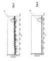
- the Fig. 1represents a typical example of a spectrum of a DVB-T signal in a UHF channel, transposed into baseband.
- the spectrumranges from -4 MHz to +4 MHz and has an interfering signal line at -2 MHz. This line may be due for example to an analog TV signal.
- the Fig. 2schematically represents a first example of specific filtering of the signal of the Fig. 1 .
- the filteris here a notch filter or frequency rejector, centered on the interfering line.
- the transfer function of the filteris indicated by reference 20. If several interfering lines are present, it is possible to perform a rejection of the various interfering lines in question.
- the Fig. 3schematically represents a second example of specific filtering of the signal of the Fig. 1 .
- the filteris here a bandpass filter eliminating the interfering line.
- the interfering linesare between -3 MHz and -2MHz.
- a band-pass filterwhose bandwidth extends from -1.5MHz to 2.5MHz, as indicated by the transfer function 30.
- the opportunistic terminalknows the frequencies of the interfering lines, these lines will be sent back by a notch filter (s) or, alternatively, the signal transposed into baseband will be filtered by a bandpass filter eliminating them.
- the average and the variance of the modulus of this spectral densityare then determined, namely m and ⁇ 2 , respectively.
- a band-pass filteris then chosen which eliminates the frequencies ⁇ x ⁇ S x - ⁇ x + .
- the transfer function H x of a filter rejecting the band [ x - x + ]is determined, and finally a band-stop filter (s) of function is used. transfer ⁇ x ⁇ S H x .
- a decimation filtering of the sampled signalcan be performed.
- the decimation ratewill then be appropriately chosen to eliminate the interfering lines. For example, if the baseband signal is in the [-4MHz 4MHz] band and has been sampled at the Nyquist frequency (8MHz), and the interfering line has been determined to be -2MHz, a rate of decimation of 4.
- the sampled signal thus decimatedis then in the band [-1MHz 1MHz] and no longer satisfies the Nyquist criterion.
- the folding of the interfering line due to under samplingis done on the zero frequency.
- the frequency f intis sampled, that is to say that a filtering by decimation at the rate 2 B / f int to finally get a signal in the band [- f int , + f int ].
- OFDM signal detectionis based on the cyclostationnarity properties of the filtered signal. More precisely, the presence of an OFDM signal in the band of interest will be detected if said filtered signal, and thus devoid of the interfering line (s), is cyclostationary.
- the value ⁇ max of the time difference corresponding to the maximum of the autocorrelation function Rs a ( t , ⁇ ), possibly normalized,is sought. If an OFDM signal is present in the received signal, it can be shown that the value ⁇ max corresponds to the useful signal duration of the OFDM symbol.
- Rs a ( t, ⁇ max )is then a periodic function in t and of periodicity equal to the length T s OFDM symbols.
- the spectrum of Rs a ( t , ⁇ max )is therefore a spectrum of lines spaced by 1 / T s , the fundamental line being located at 1 / T s .
- the first detection methoddetermines the presence of an OFDM signal if a periodicity exists in Rs a ( t, ⁇ max ) or, if the amplitude of the fundamental line in the spectrum of Rs a ( t , ⁇ max ) exceeds one predetermined threshold.
- the k ⁇ + ⁇ , k ⁇ zare the cyclic frequencies and ⁇ .> t is the time average.
- the second detection methodoperates jointly on these two parameters and is, for this reason, more resistant to noise.
- T eis the sampling period after decimation.
- the decimationdoes not modify the position of the lines of Rs a ( t , ⁇ max ) as long as ⁇ max >> T e .
- the value of the threshold J 0can be determined empirically from the maxima of the discrimination function observed for OFDM signals having different signal-to-noise ratios.
Landscapes
- Engineering & Computer Science (AREA)
- Computer Networks & Wireless Communication (AREA)
- Signal Processing (AREA)
- Monitoring And Testing Of Transmission In General (AREA)
- Noise Elimination (AREA)
Description
Translated fromFrenchLa présente invention concerne le domaine de la détection de la présence d'un signal OFDM. Elle trouve notamment application dans les systèmes radio opportunistes.The present invention relates to the field of detecting the presence of an OFDM signal. It finds particular application in opportunistic radio systems.
L'encombrement de plus en plus important du spectre a conduit à envisager des systèmes de télécommunication capables de coexister avec les systèmes à bandes de fréquence déjà allouées, dits primaires. Deux stratégies de coexistence font actuellement l'objet d'importantes recherches. La première consiste à utiliser un niveau de signal très faible grâce à un très fort étalement de spectre, c'est la voie suivie par les systèmes ultra-large bande encore dénommés UWB (Ultra Wide Band). La seconde consiste à utiliser de manière opportuniste une partie du spectre ponctuellement ou temporairement inoccupée, c'est la voie dite de radio opportuniste (ouCognitive Radio). On trouvera une description de la radio opportuniste dans la thèse fondatrice de
Le principe de la radio opportuniste a été notamment retenu pour le développement des réseaux sans fil à longue portée encore dénommés WRAN (Wireless Regional Area Network). Ces réseaux font actuellement l'objet d'un processus de standardisation au sein du groupe de travail de IEEE 802.22. Plus précisément, cette norme en cours d'élaboration propose d'utiliser de manière opportuniste les bandes UHF et VHF vacantes pour réaliser une transmission sans fil point à point dans un réseau WRAN. Il est en particulier prévu que les bandes UHF allouées au système de télévision à diffusion par voie terrestre DVB-T (Digital Video Broadcast-Terrestrial) puissent être utilisées à cette fin. La norme DVB-T fait appel à une modulation OFDM (Orthogonal Frequency Division Multiplexing) pour transmettre des flux vidéo/audio compressés. On trouvera une introduction à la norme IEEE 802.22 dans l'article de
Avant de pouvoir émettre dans une bande UHF donnée, il est nécessaire qu'un émetteur du réseau WRAN puisse déterminer si un signal OFDM est présent dans cette bande, et le cas échéant, d'en estimer les paramètres temporels tels que la longueur du préfixe, la longueur utile ou de la longueur totale du symbole OFDM.Before being able to transmit in a given UHF band, it is necessary for a transmitter of the WRAN network to be able to determine if an OFDM signal is present in this band, and if necessary, to estimate the temporal parameters such as the length of the prefix , the useful length or the total length of the OFDM symbol.
L'article de
La demande européenne
La demande internationale
L'article de
Toutefois, la détection d'un signal OFDM et l'estimation subséquente de ses paramètres temporels peuvent être entachées d'erreur en présence d'un signal interférent dans la bande de fréquence d'intérêt. Ainsi, le terminal opportuniste peut conclure indûment à la présence d'un signal OFDM et s'abstenir dans une bande pourtant disponible. Réciproquement, le terminal peut conclure par erreur à l'absence d'un signal opportuniste et transmettre alors dans une bande occupée par le système primaire, avec les risques d'interférence que cette transmission peut occasionner.However, the detection of an OFDM signal and the subsequent estimation of its time parameters may be affected by error in the presence of an interfering signal in the frequency band of interest. Thus, the opportunistic terminal may conclude unduly the presence of an OFDM signal and abstain in a band yet available. Reciprocally, the terminal may erroneously conclude the absence of an opportunistic signal and then transmit in a band occupied by the primary system, with the risk of interference that this transmission may cause.
Un premier but de la présente invention est de proposer une méthode permettant de déterminer avec une fiabilité accrue si un signal OFDM est présent ou absent dans une bande de fréquence d'intérêt ce, même en présence d'un signal interférent dans cette bande.A first object of the present invention is to propose a method making it possible to determine with greater reliability whether an OFDM signal is present or absent in a frequency band of interest ce, even in the presence of an interfering signal in this band.
La présente invention est définie par une méthode de détection de présence d'un signal OFDM dans un signal reçu, selon laquelle ledit signal reçu est transposé en bande de base et soumis à un filtrage passe-bande correspondant à une bande d'intérêt avant d'être échantillonné. Le signal ainsi échantillonné subit un second filtrage destiné à supprimer au moins une raie interférente dans la bande d'intérêt et la présence d'un signal OFDM est détectée si le signal filtré par le second filtrage est cyclostationnaire.The present invention is defined by a method of detecting the presence of an OFDM signal in a received signal, according to which said received signal is transposed into baseband and bandpass filtering corresponding to a band of interest before being sampled. The signal thus sampled undergoes a second filtering intended to remove at least one interfering line in the band of interest and the presence of an OFDM signal is detected if the signal filtered by the second filtering is cyclostationary.
Pour déterminer la/les raie(s) interférente(s), on calcule avantageusement la densité spectrale du signal échantillonné, on détermine ensuite la valeur moyennem et la variance σ2 de cette densité spectrale, puis l'on détermine les points du spectre dont l'amplitude est supérieure àm+λσ2, où λ est supérieur à 1.In order to determine the interfering line (s), the spectral density of the sampled signal is advantageously calculated, the mean valuem and the variance σ2 of this spectral density are then determined, then the points of the spectrum are determined. whose amplitude is greater thanm + λσ2 , where λ is greater than 1.
Selon une première variante, le second filtrage est un filtrage passe-bande éliminant la/les raie(s) interférente(s).According to a first variant, the second filtering is a bandpass filtering eliminating the interfering line (s).
Selon une seconde variante, le second filtrage est un filtrage coupe-bande(s) éliminant la/les raie(s) interférente(s).According to a second variant, the second filtering is a band-stop filtering (s) eliminating the interfering line (s).
Les fonctions de transfert élémentaires des différents filtres coupe-bandes sont obtenues en déterminant pour chaque pointx du spectre dont la valeur de densité spectrale excèdem+λσ2, le premier point à sa droite,x+=x+εd, ainsi que le premier point à sa gauchex-=x-εg dont la valeur de densité spectrale est égale à m, la fonction de transfert élémentaire correspondante étant adaptée à réjecter la bande de fréquences [x-x+].The elementary transfer functions of the different notch filters are obtained by determining for each pointx of the spectrum whose spectral density value exceedsm + λσ2 , the first point on its right,x+ =x + εd , as well as the first point to its leftx- =x -εg whose spectral density value is equal to m, the corresponding elementary transfer function being adapted to reject the frequency band [x- x+ ].
Selon une troisième variante, le second filtrage comprend une étape de décimation du dit signal échantillonné.According to a third variant, the second filtering comprises a step of decimating said sampled signal.
Selon un premier mode de réalisation de la méthode de détection, on calcule la fonction d'autocorrélationRsa(t,τ) du signal filtré par le second filtrage et l'on détermine la valeur τmax de l'écart temporel correspondant au maximum de la fonction d'autocorrélation, la présence d'un signal OFDM étant détectée siRsa(t,τmax) présente une périodicité en temps.According to a first embodiment of the detection method, the autocorrelation functionRsa (t , τ) of the signal filtered by the second filtering is calculated and the value τmax of the time difference corresponding to the maximum is determined. of the autocorrelation function, the presence of an OFDM signal being detected ifRsa (t , τmax ) has a periodicity in time.
On détermine ensuite siRsa(t,τmax) présente une périodicité en temps en effectuant la transformée de Fourier du signal filtré par le second filtrage et en comparant l'amplitude d'une raie fondamentale du spectre obtenu à une valeur de seuil prédéterminé.It is then determined whetherRsa (t , τmax ) has a periodicity in time by performing the Fourier transform of the signal filtered by the second filtering and comparing the amplitude of a fundamental line of the spectrum obtained with a predetermined threshold value. .
Selon un second mode de réalisation de la méthode de détection, on calcule les coefficients de corrélation cyclique


La présence d'un signal OFDM est détectée si le maximum de la fonction d'autocorrélation (J(α̂,β̂)) est supérieur à un seuil prédéterminé (J0).The presence of an OFDM signal is detected if the maximum of the autocorrelation function (J (α, β)) is greater than a predetermined threshold (J0 ).
D'autres caractéristiques et avantages de l'invention apparaîtront à la lecture d'un mode de réalisation préférentiel de l'invention fait en référence aux figures jointes parmi lesquelles :
- La
Fig. 1 représente un exemple de spectre d'un signal DVB-T transposé en bande de base ; - La
Fig. 2 représente un premier exemple de filtrage spécifique du signal de laFig. 1 , préalablement à une recherche de cyclostationnarité ; - La
Fig. 3 représente un second exemple de filtrage spécifique du signal de laFig. 1 , préalablement à une recherche de cyclostationnarité ; - La
Fig. 4 illustre le traitement du signal de laFig. 1 par une première méthode de détection ; - La
Fig. 5 illustre le traitement du signal de laFig. 1 par une seconde méthode de détection.
- The
Fig. 1 represents an example of a spectrum of a DVB-T signal transposed into baseband; - The
Fig. 2 represents a first example of specific filtering of the signal of theFig. 1 , prior to a search for cyclostationnarity; - The
Fig. 3 represents a second example of specific filtering of the signal of theFig. 1 , prior to a search for cyclostationnarity; - The
Fig. 4 illustrates the signal processing of theFig. 1 by a first detection method; - The
Fig. 5 illustrates the signal processing of theFig. 1 by a second detection method.
Nous considèrerons dans la suite un terminal d'un système radio opportuniste souhaitant déterminer si un signal OFDM est présent ou absent dans une bande de fréquence d'intérêt.We will consider in the following a terminal of an opportunistic radio system wishing to determine if an OFDM signal is present or absent in a frequency band of interest.
Le terminal en question peut être par exemple un émetteur d'un réseau WRAN recherchant une bande disponible dans le spectre DVB-T. On rappelle que le spectre DVB-T utilisé par la TNT (Télévision Numérique Terrestre) utilise les canaux UHF 21 à 69 (occupant la bande spectrale de 470 à 862 MHz), chaque canal présentant une largeur de bande de 8 MHz.The terminal in question can be for example a transmitter of a WRAN network looking for an available band in the DVB-T spectrum. It is recalled that the DVB-T spectrum used by DTT (Terrestrial Digital Television) uses UHF channels 21 to 69 (occupying the spectral band 470 to 862 MHz), each channel having a bandwidth of 8 MHz.
Lorsque le terminal opportuniste souhaite déterminer si une bande d'intérêt, c'est-à-dire dans l'exemple précédent, un des canaux UHF, est occupé par un signal OFDM, le terminal opportuniste démodule le signal reçu à la fréquence centrale de la bande d'intérêt, c'est-à-dire à la fréquence correspondante du canal dans l'exemple précité. Le signal ainsi transposé en bande de base est ensuite filtré à l'aide d'un filtre passe-bande correspondant à la largeur de la bande d'intérêt (-4MHz à +4MHz pour un des canaux UHF), puis échantillonné à la fréquence de Nyquist du signal ainsi filtré (par exemple 8 Mhz).When the opportunistic terminal wishes to determine if a band of interest, that is to say in the previous example, one of the UHF channels, is occupied by an OFDM signal, the opportunistic terminal demodulates the received signal at the central frequency of the band of interest, that is to say at the corresponding frequency of the channel in the above example. The signal thus transposed into baseband is then filtered using a band-pass filter corresponding to the width of the band of interest (-4MHz to + 4MHz for one of the UHF channels), and then sampled at the frequency Nyquist of the signal thus filtered (for example 8 Mhz).
Alors que les méthodes de détection selon l'état de la technique recherchent si le signal ainsi obtenu présente un cyclostationnarité, autrement dit si la fonction d'autocorrélation de ce signal présente une périodicité, la présente invention applique un filtrage spécifique avant de procéder à cette recherche.While the detection methods according to the state of the art look for whether the signal thus obtained has a cyclostationnarity, in other words if the autocorrelation function of this signal has a periodicity, the present invention applies a specific filtering before proceeding with this signal. research.
Plus précisément, ledit filtrage spécifique peut être un filtrage passe-bande, un filtrage réjecteur de bande, ou encore être obtenu par décimation du signal échantillonné.More precisely, said specific filtering may be band-pass filtering, band rejection filtering, or else be obtained by decimation of the sampled signal.
De manière surprenante, il a été noté, que le fait d'opérer un filtrage passe-bande ou réjecteur de bande pour éliminer une ou des raie(s) interférente(s) au sein de la bande d'intérêt n'altérait pas de manière significative les propriétés de cyclostationnarité du signal OFDM. L'élimination des raies interférentes réduit considérablement la probabilité de fausse détection d'un signal OFDM (détection d'un tel signal alors qu'il est en fait absent, absence de détection d'un tel signal alors qu'il est effectivement présent) tout en conservant sensiblement ses propriétés de cyclostationnarité. En outre, si l'étape de détection conclut à la présence d'un signal OFDM dans la bande d'intérêt, il est possible d'estimer avec une fiabilité accrue les paramètres temporels à partir du signal ayant subi ledit filtrage spécifique.Surprisingly, it has been noted that band-pass or band-rejection filtering to eliminate interfering line (s) within the band of interest does not alter the bandwidth. significantly the cyclostationnarity properties of the OFDM signal. The elimination of the interfering lines considerably reduces the probability of false detection of an OFDM signal (detection of such a signal when it is in fact absent, absence of detection of such a signal when it is actually present) while substantially maintaining its cyclostationnarity properties. In addition, if the detection step concludes the presence of an OFDM signal in the band of interest, it is possible to estimate with greater reliability the time parameters from the signal having undergone said specific filtering.
La
La
La
Si plusieurs raies interférentes sont présentes, on choisit un filtre passe-bande ne gardant que la partie du spectre du signal non affectée par ces raies interférentes.If several interfering lines are present, one chooses a band-pass filter keeping only the part of the spectrum of the signal not affected by these interfering lines.
De manière générale, si le terminal opportuniste connaît les fréquences des raies interférentes, ces raies seront réjectées par un filtre coupe-bande(s) ou, alternativement le signal transposé en bande de base sera filtré par un filtrage passe-bande les éliminant.In general, if the opportunistic terminal knows the frequencies of the interfering lines, these lines will be sent back by a notch filter (s) or, alternatively, the signal transposed into baseband will be filtered by a bandpass filter eliminating them.
A défaut de connaîtrea priori les raies interférentes, le terminal peut déterminer leurs positions spectrales en procédant comme suait :
- Dans un premier temps, on estime la densité spectrale de puissance du signal transposé en bande de base échantillonné, par exemple au moyen d'une transformée de Fourier (FFT) dont on calcule ensuite le module au carré.
- In a first step, the spectral power density of the sampled baseband transposed signal is estimated, for example by means of a Fourier Transform (FFT) whose square modulus is then calculated.
On détermine ensuite la moyenne et la variance du module de cette densité spectrale soit m et σ2, respectivement.The average and the variance of the modulus of this spectral density are then determined, namely m and σ2 , respectively.
On recherche ensuite les points du spectre dont la valeur de densité spectrale est supérieure à la valeurm+λσ2 où λ est un réel supérieur à 1, par exemple égal λ=3. SoitS, l'ensemble des points de cette liste.We then look for the points of the spectrum whose spectral density value is greater than the valuem + λσ2 where λ is a real greater than 1, for example equal to λ = 3. LetS be the set of points in this list.
Pour chaque pointx∈S, on détermine le premier point à droitex+=x+εd ainsi que le premier point à gauchex-=x-εg dont la valeur de densité spectrale est égale àm.For each pointx ∈S , we determine the first point to the rightx+ =x + εd and the first point to leftx- =x -εg whose spectral density value is equal tom .
Selon une première variante, on choisit ensuite un filtre passe-bande qui élimine les fréquences
Selon une seconde variante, on détermine pour chaque fréquencex∈S, la fonction de transfertHx d'un filtre rejetant la bande [x-x+] et l'on utilise en définitive un filtre coupe-bande(s) de fonction de transfert
Selon une troisième variante, alternative à un filtrage passe-bande ou coupe-bande(s), on pourra effectuer un filtrage par décimation du signal échantillonné. On choisira alors convenablement le taux de décimation pour éliminer les raies interférentes. Par exemple, si le signal en bande base est dans la bande [-4MHz 4MHz] et a été échantillonné à la fréquence de Nyquist (8MHz), et si la raie interférente a été déterminée comme étant à -2MHz, on choisira un taux de décimation de 4. Le signal échantillonné ainsi décimé est alors dans la bande [-1MHz 1MHz] et ne satisfait plus le critère de Nyquist. Cependant, le repliement de la raie interférente due au sous échantillonnage se fait sur la fréquence nulle. De manière générale si la raie interférente se trouve à ±fint dans la bande [-B,+B] du signal en bande de base on échantillonnera à la fréquencefint, c'est-à-dire que l'on effectuera un filtrage par décimation au taux 2B/fint pour obtenir en définitive un signal dans la bande [-fint,+fint].According to a third variant, alternative to band-pass filtering or band-stopper (s), a decimation filtering of the sampled signal can be performed. The decimation rate will then be appropriately chosen to eliminate the interfering lines. For example, if the baseband signal is in the [-4MHz 4MHz] band and has been sampled at the Nyquist frequency (8MHz), and the interfering line has been determined to be -2MHz, a rate of decimation of 4. The sampled signal thus decimated is then in the band [-1MHz 1MHz] and no longer satisfies the Nyquist criterion. However, the folding of the interfering line due to under sampling is done on the zero frequency. In general, if the interfering line is within ±fint in the [-B , +B ] band of the baseband signal, the frequencyfint is sampled, that is to say that a filtering by decimation at the rate 2B /fint to finally get a signal in the band [-fint , +fint ].
Le repliement des images de la raie interférente sur la fréquence nulle n'affecte pas les propriétés de cyclostationnarité du signal.The folding of the images of the interfering line on the zero frequency does not affect the cyclostationnarity properties of the signal.
La détection de signal OFDM se fait à partir des propriétés de cyclostationnarité du signal filtré. Plus précisément, on détectera la présence d'un signal OFDM dans la bande d'intérêt si ledit signal filtré, et donc dépourvu de la(les) raie(s) interférente(s), est cyclostationnaire.
La fonction d'autocorrélation du signal filtré peut s'exprimer sous la forme :
où E{.} désigne l'espérance mathématique,sa(t) le signal filtré et τ l'écart temporel pour lequel on calcule la corrélation.OFDM signal detection is based on the cyclostationnarity properties of the filtered signal. More precisely, the presence of an OFDM signal in the band of interest will be detected if said filtered signal, and thus devoid of the interfering line (s), is cyclostationary.
The autocorrelation function of the filtered signal can be expressed as:
where E {.} denotes the mathematical expectation,sa (t) the filtered signal and τ the time difference for which the correlation is calculated.
Selon une première méthode de détection, on recherche la valeur τmax de l'écart temporel qui correspond au maximum de la fonction d'autocorrélationRsa(t,τ), éventuellement normalisée. Si un signal OFDM est présent dans le signal reçu, on peut montrer que la valeur τmax correspond à la durée de signal utile du symbole OFDM.Rsa(t,τmax) est alors une fonction périodique en t et de périodicité égale à la longueurTs des symboles OFDM. Le spectre deRsa(t,τmax) est donc un spectre de raies espacées de 1/Ts, la raie fondamentale étant située à 1/Ts.According to a first detection method, the value τmax of the time difference corresponding to the maximum of the autocorrelation functionRsa (t , τ), possibly normalized, is sought. If an OFDM signal is present in the received signal, it can be shown that the value τmax corresponds to the useful signal duration of the OFDM symbol.Rsa (t, τmax ) is then a periodic function in t and of periodicity equal to the lengthTs OFDM symbols. The spectrum ofRsa (t , τmax ) is therefore a spectrum of lines spaced by 1 /Ts , the fundamental line being located at 1 /Ts .
La première méthode de détection détermine la présence d'un signal OFDM si une périodicité existe dansRsa(t,τmax) ou, si l'amplitude de la raie fondamentale dans le spectre deRsa(t,τmax) excède un seuil prédéterminé.The first detection method determines the presence of an OFDM signal if a periodicity exists inRsa (t, τmax ) or, if the amplitude of the fundamental line in the spectrum ofRsa (t , τmax ) exceeds one predetermined threshold.
La seconde méthode de détection a été exposée en détail dans la demande de brevet n°
Selon cette méthode, on calcule les coefficients de corrélation cyclique

où les

According to this method, the cyclic correlation coefficients are calculated
where the
On définit une fonction de discrimination par :
oùK est une valeur entière strictement supérieure à 1, indiquant le nombre de fréquences cycliques que l'on prend en compte dans l'estimation. Cette fonction de discrimination permet de déterminer si, pour un écart temporel τ=α donné, la fonction d'autocorrélation présente en fonction du temps des pics se répétant avec une périodicité α+β.A discrimination function is defined by:
whereK is an integer value strictly greater than 1, indicating the number of cyclic frequencies that are taken into account in the estimation. This discriminating function makes it possible to determine whether, for a given time difference τ = α, the autocorrelation function exhibits, as a function of time, peaks repeating with a periodicity α + β.
En présence d'un signal OFDM de paramètres temporelsTu etTs=Tu+Tp, oùTu est la durée utile,Tp la durée du préfixe etTs la durée des symboles OFDM, la fonction de discriminationJ(α,β) présentera un maximumJ pour α=Tu et β=Tp. Ce maximum sera sensiblement supérieur au maximumJ0 qui serait atteint par la fonctionJ(α,β) en absence de signal OFDM.In the presence of an OFDM signal of time parametersTu andTs =Tu +Tp , whereTu is the useful life,Tp the duration of the prefix andTs the duration of the OFDM symbols, the discrimination functionJ (α, β) will have a maximumJ for α =Tu and β =Tp . This maximum will be substantially greater than the maximumJ0 that would be reached by the functionJ (α, β) in the absence of an OFDM signal.
De manière générale, la présence d'un signal OFDM sera détectée s'il existe un couple de valeurs α et β telles queJ(α,β)>J0.In general, the presence of an OFDM signal will be detected if there exists a pair of values α and β such thatJ (α, β)>J0 .
On notera qu'à la différence de la première méthode de détection qui procède en deux étapes successives, en estimant tout d'abord la longueur utileTu puis la longueur totaleTs des symboles OFDM, la seconde méthode de détection opère conjointement sur ces deux paramètres et est, pour cette raison, plus résistante au bruit.It will be noted that, unlike the first detection method, which proceeds in two successive steps, by first estimating the useful lengthTu and then the total lengthTs of the OFDM symbols, the second detection method operates jointly on these two parameters and is, for this reason, more resistant to noise.
En pratique, on calcule les coefficients de corrélation cyclique sur une longueur de fenêtre finieU, à partir du signal échantillonné, soit :
dans lequel on a défini les valeurs réduites

in which the reduced values have been defined
On notera que si le signal échantillonné est décimé,Te est la période d'échantillonnage après décimation. La décimation ne modifie pas la position des raies deRsa(t,τmax) pour autant que τmax>>Te.Note that if the sampled signal is decimated,Te is the sampling period after decimation. The decimation does not modify the position of the lines ofRsa (t , τmax ) as long as τmax >>Te .
On déduit la fonction de discrimination à partir de l'expression (4), soit :
Ou, de manière équivalente, par simple translation de α :
Or, in an equivalent way, by simple translation of α:
On détermine ensuite les paramètres α̂ et β̂ qui maximisent la fonction de discrimination. On conclut à la présence d'un signal OFDM si :
La valeur du seuilJ0 peut être déterminée empiriquement à partir des maxima de la fonction de discrimination observés pour des signaux OFDM présentant différents rapports de signal sur bruit.The value of the thresholdJ0 can be determined empirically from the maxima of the discrimination function observed for OFDM signals having different signal-to-noise ratios.
On a illustré en
De manière similaire on a illustré en
Dans les deux cas, on peut conclure à la présence d'un signal OFDM de temps symbole correspondant à 3500.Te dans la bande d'intérêt.In both cases, it can be concluded that there is an OFDM symbol time signal corresponding to 3500.Te in the band of interest.
Claims (10)
- Method for detecting the presence of an OFDM signal in a received signal wherein said received signal is frequency down converted into baseband and made subject to a passband filtering corresponding to a band of interest before being sampled,characterised in that thus sampled signal is subjected to a second filtering for eliminating at least one interfering line in the band of interest, and that the presence of an OFDM signal is detected if the signal filtered by the second filtering is cyclostationary.
- Detection method as claimed in claim 1,characterised in that, in order to determine the interference line or lines, the spectral density of the sampled signal is calculated, the mean valuem and the variance σ2 of this spectral density are then determined, and the points on the spectrum are then determined for which the spectral density is greater thanm +λσ2, where λ is greater than 1.
- Detection method as claimed in claim 1 or 2,characterised in that the second filtering is a passband filtering that eliminates the interfering line(s).
- Detection method as claimed in claim 1,characterised in that the second filtering is a band-stop filtering that eliminates the interfering line(s).
- Detection method as claimed in claim 4,characterised in that the elementary transfer functions of the different band-stop filters are obtained by determining for each point x in the spectrum whereof the spectral density value exceedsm + λσ2, the first point to the right thereof,x+ =x + εd, and the first point to the left thereofx- =x - εg for which the spectral density value is equal tom, the corresponding elementary transfer value being adapted to reject the frequency band [x-x+].
- Detection method as claimed in claim 1 or 2,characterised in that the second filtering includes a step of decimating said sampled signal.
- Detection method as claimed in one of the previous claims,characterised in that the autocorrelation functionRsa(t,τ) of the signal filtered by the second filtering is calculated and that the value τmax of the time interval corresponding to the maximum autocorrelation function is determined, the presence of an OFDM signal being detected ifRsa(t,τmax) displays a time periodicity.
- Detection method as claimed in claim 7,characterised in that it is determined thatRsa(t,τmax) displays a time periodicity by performing a Fourier transform of the signal filtered by the second filtering and by comparing the amplitude of a fundamental line of the spectrum obtained against a preset threshold value.
- Detection method as claimed in one of claims 1 to 6,characterised in that the coefficients of cyclical correlation


- Detection method as claimed in claim 9,characterised in that the presence of an OFDM signal is detected if the maximum autocorrelation function (J(α̂,β̂)) is above a preset threshold (J0).


Applications Claiming Priority (1)
| Application Number | Priority Date | Filing Date | Title |
|---|---|---|---|
| FR0853552AFR2932039B1 (en) | 2008-05-30 | 2008-05-30 | METHOD FOR DETECTING AN OFDM SIGNAL |
Publications (2)
| Publication Number | Publication Date |
|---|---|
| EP2128998A1 EP2128998A1 (en) | 2009-12-02 |
| EP2128998B1true EP2128998B1 (en) | 2015-12-16 |
Family
ID=40453948
Family Applications (1)
| Application Number | Title | Priority Date | Filing Date |
|---|---|---|---|
| EP09161191.3ANot-in-forceEP2128998B1 (en) | 2008-05-30 | 2009-05-27 | Method for detecting an OFDM signal |
Country Status (4)
| Country | Link |
|---|---|
| US (1) | US8675745B2 (en) |
| EP (1) | EP2128998B1 (en) |
| JP (1) | JP5461889B2 (en) |
| FR (1) | FR2932039B1 (en) |
Family Cites Families (7)
| Publication number | Priority date | Publication date | Assignee | Title |
|---|---|---|---|---|
| US3656162A (en)* | 1969-09-19 | 1972-04-11 | Litton Systems Inc | Diplexer for radio communication |
| US6426983B1 (en)* | 1998-09-14 | 2002-07-30 | Terayon Communication Systems, Inc. | Method and apparatus of using a bank of filters for excision of narrow band interference signal from CDMA signal |
| JP3711117B2 (en)* | 2003-03-25 | 2005-10-26 | 株式会社東芝 | Wireless receiver |
| JP2006135674A (en)* | 2004-11-05 | 2006-05-25 | Ntt Docomo Inc | Mobile communication receiver, mobile communication transmitter, mobile communication reception method, and mobile communication transmission method |
| US7437139B2 (en)* | 2005-10-26 | 2008-10-14 | Tzero Technologies, Inc. | Method and apparatus for calibrating filtering of a transceiver |
| JP2007258904A (en)* | 2006-03-22 | 2007-10-04 | Sony Corp | Wireless communication device |
| US8160163B1 (en)* | 2007-08-06 | 2012-04-17 | University Of South Florida | Method for OFDM signal identification and parameter estimation |
- 2008
- 2008-05-30FRFR0853552Apatent/FR2932039B1/ennot_activeExpired - Fee Related
- 2009
- 2009-05-27EPEP09161191.3Apatent/EP2128998B1/ennot_activeNot-in-force
- 2009-05-28USUS12/473,899patent/US8675745B2/ennot_activeExpired - Fee Related
- 2009-05-29JPJP2009131253Apatent/JP5461889B2/ennot_activeExpired - Fee Related
Also Published As
| Publication number | Publication date |
|---|---|
| US8675745B2 (en) | 2014-03-18 |
| FR2932039B1 (en) | 2010-08-13 |
| JP5461889B2 (en) | 2014-04-02 |
| EP2128998A1 (en) | 2009-12-02 |
| US20090296841A1 (en) | 2009-12-03 |
| JP2009290875A (en) | 2009-12-10 |
| FR2932039A1 (en) | 2009-12-04 |
Similar Documents
| Publication | Publication Date | Title |
|---|---|---|
| EP0499560B1 (en) | Channel estimation system and method for COFDM transmission system | |
| EP3073695B1 (en) | Method for processing an analog signal coming from a transmission channel, in particular a signal transmitted through powerline communication | |
| EP3412012B1 (en) | Method for estimating parameters of signals contained in a frequency band | |
| EP2425597B1 (en) | Method for blind identification of an ofdm signal contained in a signal received by a telecommunication system | |
| EP0549445B1 (en) | Method for the transmission of reference signals in a multicarrier data transmission system | |
| WO2002052521A2 (en) | Radiofrequency receiver for remote meter reading and remote meter reading method comprising same | |
| EP2168336B1 (en) | Method of detecting presence of spectrally spread signals | |
| FR2854290A1 (en) | METHOD FOR DEMODULATING OFDM-TYPE SIGNALS IN THE PRESENCE OF STRONG CO-CHANNEL INTERFERING SIGNALS | |
| FR2919135A1 (en) | CYCLOSTATIONARY SIGNAL DETECTION METHOD | |
| EP1998522B1 (en) | Method for estimating OFDM signal parameters | |
| EP2128998B1 (en) | Method for detecting an OFDM signal | |
| EP1925139B1 (en) | Spectrum characterization for communication equipment | |
| EP3116136A1 (en) | Method for estimating a time-invariant transmission channel, and corresponding receiver | |
| EP2334021B1 (en) | Method for the blind estimation of ofdm signal parameters through adaptive covariance | |
| KR101196088B1 (en) | Method and apparatus for detecting co-channel interference signal in orthogonal frequency division multiple system | |
| EP2327191B1 (en) | Method for the blind estimation of OFDM signal parameters by adapted filtering | |
| FR2967540A1 (en) | METHOD FOR RECEIVING A MULTI-CARRIER SIGNAL IMPLEMENTING INTERFERENCE ESTIMATION, RECEIVING DEVICE AND COMPUTER PROGRAM THEREOF | |
| FR3056057B1 (en) | METHOD OF ADAPTIVE FILTERING OF RADIO SIGNAL MODULE IN AMPLITUDE | |
| EP2640027A1 (en) | Method of identification and detection of a radio signal for an opportunistic communication system | |
| FR2952494A1 (en) | METHOD FOR DEMODULATING A COMPOSITE SIGNAL AND CORRESPONDING DEVICE | |
| FR2973613A1 (en) | METHOD FOR DETECTING AN INTERFERENCE FREQUENCY BAND IN A VERY BROADBAND FREQUENCY RADIO SIGNAL, DEVICE AND RECEIVER THEREFOR |
Legal Events
| Date | Code | Title | Description |
|---|---|---|---|
| PUAI | Public reference made under article 153(3) epc to a published international application that has entered the european phase | Free format text:ORIGINAL CODE: 0009012 | |
| AK | Designated contracting states | Kind code of ref document:A1 Designated state(s):AT BE BG CH CY CZ DE DK EE ES FI FR GB GR HR HU IE IS IT LI LT LU LV MC MK MT NL NO PL PT RO SE SI SK TR | |
| RAP1 | Party data changed (applicant data changed or rights of an application transferred) | Owner name:COMMISSARIAT A L'ENERGIE ATOMIQUE ET AUX ENERGIES | |
| 17P | Request for examination filed | Effective date:20100601 | |
| GRAP | Despatch of communication of intention to grant a patent | Free format text:ORIGINAL CODE: EPIDOSNIGR1 | |
| INTG | Intention to grant announced | Effective date:20150720 | |
| GRAS | Grant fee paid | Free format text:ORIGINAL CODE: EPIDOSNIGR3 | |
| GRAA | (expected) grant | Free format text:ORIGINAL CODE: 0009210 | |
| AK | Designated contracting states | Kind code of ref document:B1 Designated state(s):AT BE BG CH CY CZ DE DK EE ES FI FR GB GR HR HU IE IS IT LI LT LU LV MC MK MT NL NO PL PT RO SE SI SK TR | |
| REG | Reference to a national code | Ref country code:GB Ref legal event code:FG4D Free format text:NOT ENGLISH | |
| REG | Reference to a national code | Ref country code:CH Ref legal event code:EP | |
| REG | Reference to a national code | Ref country code:IE Ref legal event code:FG4D Free format text:LANGUAGE OF EP DOCUMENT: FRENCH | |
| REG | Reference to a national code | Ref country code:AT Ref legal event code:REF Ref document number:765999 Country of ref document:AT Kind code of ref document:T Effective date:20160115 | |
| REG | Reference to a national code | Ref country code:DE Ref legal event code:R096 Ref document number:602009035203 Country of ref document:DE | |
| REG | Reference to a national code | Ref country code:NL Ref legal event code:MP Effective date:20151216 | |
| REG | Reference to a national code | Ref country code:LT Ref legal event code:MG4D | |
| PG25 | Lapsed in a contracting state [announced via postgrant information from national office to epo] | Ref country code:NO Free format text:LAPSE BECAUSE OF FAILURE TO SUBMIT A TRANSLATION OF THE DESCRIPTION OR TO PAY THE FEE WITHIN THE PRESCRIBED TIME-LIMIT Effective date:20160316 Ref country code:HR Free format text:LAPSE BECAUSE OF FAILURE TO SUBMIT A TRANSLATION OF THE DESCRIPTION OR TO PAY THE FEE WITHIN THE PRESCRIBED TIME-LIMIT Effective date:20151216 Ref country code:LT Free format text:LAPSE BECAUSE OF FAILURE TO SUBMIT A TRANSLATION OF THE DESCRIPTION OR TO PAY THE FEE WITHIN THE PRESCRIBED TIME-LIMIT Effective date:20151216 | |
| REG | Reference to a national code | Ref country code:AT Ref legal event code:MK05 Ref document number:765999 Country of ref document:AT Kind code of ref document:T Effective date:20151216 | |
| REG | Reference to a national code | Ref country code:FR Ref legal event code:PLFP Year of fee payment:8 | |
| PG25 | Lapsed in a contracting state [announced via postgrant information from national office to epo] | Ref country code:NL Free format text:LAPSE BECAUSE OF FAILURE TO SUBMIT A TRANSLATION OF THE DESCRIPTION OR TO PAY THE FEE WITHIN THE PRESCRIBED TIME-LIMIT Effective date:20151216 Ref country code:SE Free format text:LAPSE BECAUSE OF FAILURE TO SUBMIT A TRANSLATION OF THE DESCRIPTION OR TO PAY THE FEE WITHIN THE PRESCRIBED TIME-LIMIT Effective date:20151216 Ref country code:GR Free format text:LAPSE BECAUSE OF FAILURE TO SUBMIT A TRANSLATION OF THE DESCRIPTION OR TO PAY THE FEE WITHIN THE PRESCRIBED TIME-LIMIT Effective date:20160317 Ref country code:FI Free format text:LAPSE BECAUSE OF FAILURE TO SUBMIT A TRANSLATION OF THE DESCRIPTION OR TO PAY THE FEE WITHIN THE PRESCRIBED TIME-LIMIT Effective date:20151216 Ref country code:LV Free format text:LAPSE BECAUSE OF FAILURE TO SUBMIT A TRANSLATION OF THE DESCRIPTION OR TO PAY THE FEE WITHIN THE PRESCRIBED TIME-LIMIT Effective date:20151216 | |
| PG25 | Lapsed in a contracting state [announced via postgrant information from national office to epo] | Ref country code:ES Free format text:LAPSE BECAUSE OF FAILURE TO SUBMIT A TRANSLATION OF THE DESCRIPTION OR TO PAY THE FEE WITHIN THE PRESCRIBED TIME-LIMIT Effective date:20151216 Ref country code:CZ Free format text:LAPSE BECAUSE OF FAILURE TO SUBMIT A TRANSLATION OF THE DESCRIPTION OR TO PAY THE FEE WITHIN THE PRESCRIBED TIME-LIMIT Effective date:20151216 Ref country code:IT Free format text:LAPSE BECAUSE OF FAILURE TO SUBMIT A TRANSLATION OF THE DESCRIPTION OR TO PAY THE FEE WITHIN THE PRESCRIBED TIME-LIMIT Effective date:20151216 | |
| PGFP | Annual fee paid to national office [announced via postgrant information from national office to epo] | Ref country code:DE Payment date:20160516 Year of fee payment:8 Ref country code:GB Payment date:20160518 Year of fee payment:8 | |
| PG25 | Lapsed in a contracting state [announced via postgrant information from national office to epo] | Ref country code:IS Free format text:LAPSE BECAUSE OF FAILURE TO SUBMIT A TRANSLATION OF THE DESCRIPTION OR TO PAY THE FEE WITHIN THE PRESCRIBED TIME-LIMIT Effective date:20160416 Ref country code:AT Free format text:LAPSE BECAUSE OF FAILURE TO SUBMIT A TRANSLATION OF THE DESCRIPTION OR TO PAY THE FEE WITHIN THE PRESCRIBED TIME-LIMIT Effective date:20151216 Ref country code:PT Free format text:LAPSE BECAUSE OF FAILURE TO SUBMIT A TRANSLATION OF THE DESCRIPTION OR TO PAY THE FEE WITHIN THE PRESCRIBED TIME-LIMIT Effective date:20160418 Ref country code:SK Free format text:LAPSE BECAUSE OF FAILURE TO SUBMIT A TRANSLATION OF THE DESCRIPTION OR TO PAY THE FEE WITHIN THE PRESCRIBED TIME-LIMIT Effective date:20151216 Ref country code:RO Free format text:LAPSE BECAUSE OF FAILURE TO SUBMIT A TRANSLATION OF THE DESCRIPTION OR TO PAY THE FEE WITHIN THE PRESCRIBED TIME-LIMIT Effective date:20151216 Ref country code:EE Free format text:LAPSE BECAUSE OF FAILURE TO SUBMIT A TRANSLATION OF THE DESCRIPTION OR TO PAY THE FEE WITHIN THE PRESCRIBED TIME-LIMIT Effective date:20151216 Ref country code:BE Free format text:LAPSE BECAUSE OF NON-PAYMENT OF DUE FEES Effective date:20160531 | |
| PGFP | Annual fee paid to national office [announced via postgrant information from national office to epo] | Ref country code:FR Payment date:20160527 Year of fee payment:8 | |
| REG | Reference to a national code | Ref country code:DE Ref legal event code:R097 Ref document number:602009035203 Country of ref document:DE | |
| PLBE | No opposition filed within time limit | Free format text:ORIGINAL CODE: 0009261 | |
| STAA | Information on the status of an ep patent application or granted ep patent | Free format text:STATUS: NO OPPOSITION FILED WITHIN TIME LIMIT | |
| PG25 | Lapsed in a contracting state [announced via postgrant information from national office to epo] | Ref country code:PL Free format text:LAPSE BECAUSE OF FAILURE TO SUBMIT A TRANSLATION OF THE DESCRIPTION OR TO PAY THE FEE WITHIN THE PRESCRIBED TIME-LIMIT Effective date:20151216 Ref country code:DK Free format text:LAPSE BECAUSE OF FAILURE TO SUBMIT A TRANSLATION OF THE DESCRIPTION OR TO PAY THE FEE WITHIN THE PRESCRIBED TIME-LIMIT Effective date:20151216 | |
| 26N | No opposition filed | Effective date:20160919 | |
| PG25 | Lapsed in a contracting state [announced via postgrant information from national office to epo] | Ref country code:LU Free format text:LAPSE BECAUSE OF FAILURE TO SUBMIT A TRANSLATION OF THE DESCRIPTION OR TO PAY THE FEE WITHIN THE PRESCRIBED TIME-LIMIT Effective date:20160527 | |
| REG | Reference to a national code | Ref country code:CH Ref legal event code:PL | |
| PG25 | Lapsed in a contracting state [announced via postgrant information from national office to epo] | Ref country code:LI Free format text:LAPSE BECAUSE OF NON-PAYMENT OF DUE FEES Effective date:20160531 Ref country code:CH Free format text:LAPSE BECAUSE OF NON-PAYMENT OF DUE FEES Effective date:20160531 | |
| REG | Reference to a national code | Ref country code:IE Ref legal event code:MM4A | |
| PG25 | Lapsed in a contracting state [announced via postgrant information from national office to epo] | Ref country code:SI Free format text:LAPSE BECAUSE OF FAILURE TO SUBMIT A TRANSLATION OF THE DESCRIPTION OR TO PAY THE FEE WITHIN THE PRESCRIBED TIME-LIMIT Effective date:20151216 | |
| PG25 | Lapsed in a contracting state [announced via postgrant information from national office to epo] | Ref country code:IE Free format text:LAPSE BECAUSE OF NON-PAYMENT OF DUE FEES Effective date:20160527 | |
| REG | Reference to a national code | Ref country code:DE Ref legal event code:R119 Ref document number:602009035203 Country of ref document:DE | |
| GBPC | Gb: european patent ceased through non-payment of renewal fee | Effective date:20170527 | |
| REG | Reference to a national code | Ref country code:FR Ref legal event code:ST Effective date:20180131 | |
| PG25 | Lapsed in a contracting state [announced via postgrant information from national office to epo] | Ref country code:DE Free format text:LAPSE BECAUSE OF NON-PAYMENT OF DUE FEES Effective date:20171201 Ref country code:GB Free format text:LAPSE BECAUSE OF NON-PAYMENT OF DUE FEES Effective date:20170527 | |
| PG25 | Lapsed in a contracting state [announced via postgrant information from national office to epo] | Ref country code:CY Free format text:LAPSE BECAUSE OF FAILURE TO SUBMIT A TRANSLATION OF THE DESCRIPTION OR TO PAY THE FEE WITHIN THE PRESCRIBED TIME-LIMIT Effective date:20151216 Ref country code:HU Free format text:LAPSE BECAUSE OF FAILURE TO SUBMIT A TRANSLATION OF THE DESCRIPTION OR TO PAY THE FEE WITHIN THE PRESCRIBED TIME-LIMIT; INVALID AB INITIO Effective date:20090527 Ref country code:FR Free format text:LAPSE BECAUSE OF NON-PAYMENT OF DUE FEES Effective date:20170531 | |
| PG25 | Lapsed in a contracting state [announced via postgrant information from national office to epo] | Ref country code:MK Free format text:LAPSE BECAUSE OF FAILURE TO SUBMIT A TRANSLATION OF THE DESCRIPTION OR TO PAY THE FEE WITHIN THE PRESCRIBED TIME-LIMIT Effective date:20151216 Ref country code:MT Free format text:LAPSE BECAUSE OF FAILURE TO SUBMIT A TRANSLATION OF THE DESCRIPTION OR TO PAY THE FEE WITHIN THE PRESCRIBED TIME-LIMIT Effective date:20151216 Ref country code:TR Free format text:LAPSE BECAUSE OF FAILURE TO SUBMIT A TRANSLATION OF THE DESCRIPTION OR TO PAY THE FEE WITHIN THE PRESCRIBED TIME-LIMIT Effective date:20151216 Ref country code:MC Free format text:LAPSE BECAUSE OF FAILURE TO SUBMIT A TRANSLATION OF THE DESCRIPTION OR TO PAY THE FEE WITHIN THE PRESCRIBED TIME-LIMIT Effective date:20151216 | |
| PG25 | Lapsed in a contracting state [announced via postgrant information from national office to epo] | Ref country code:BG Free format text:LAPSE BECAUSE OF FAILURE TO SUBMIT A TRANSLATION OF THE DESCRIPTION OR TO PAY THE FEE WITHIN THE PRESCRIBED TIME-LIMIT Effective date:20151216 |