EP2127467B1 - Active hearing protection system - Google Patents
Active hearing protection systemDownload PDFInfo
- Publication number
- EP2127467B1 EP2127467B1EP06841011.7AEP06841011AEP2127467B1EP 2127467 B1EP2127467 B1EP 2127467B1EP 06841011 AEP06841011 AEP 06841011AEP 2127467 B1EP2127467 B1EP 2127467B1
- Authority
- EP
- European Patent Office
- Prior art keywords
- audio signal
- signal processing
- audio
- audio signals
- microphone
- Prior art date
- Legal status (The legal status is an assumption and is not a legal conclusion. Google has not performed a legal analysis and makes no representation as to the accuracy of the status listed.)
- Active
Links
- 230000005236sound signalEffects0.000claimsdescription149
- 230000006854communicationEffects0.000claimsdescription76
- 238000004891communicationMethods0.000claimsdescription76
- 210000000613ear canalAnatomy0.000claimsdescription15
- 230000006870functionEffects0.000claimsdescription12
- 238000004458analytical methodMethods0.000claimsdescription6
- 206010011878DeafnessDiseases0.000claimsdescription5
- 230000002457bidirectional effectEffects0.000claimsdescription5
- 230000010370hearing lossEffects0.000claimsdescription5
- 231100000888hearing lossToxicity0.000claimsdescription5
- 208000016354hearing loss diseaseDiseases0.000claimsdescription5
- 238000000034methodMethods0.000claimsdescription4
- 230000004913activationEffects0.000claimsdescription3
- 230000001419dependent effectEffects0.000claimsdescription3
- 238000001914filtrationMethods0.000claimsdescription3
- 230000005540biological transmissionEffects0.000claimsdescription2
- 230000000694effectsEffects0.000claimsdescription2
- 210000003127kneeAnatomy0.000description7
- 230000005534acoustic noiseEffects0.000description3
- 238000010586diagramMethods0.000description3
- 230000009467reductionEffects0.000description3
- 210000000883ear externalAnatomy0.000description2
- 239000000843powderSubstances0.000description2
- 239000004952PolyamideSubstances0.000description1
- 230000009471actionEffects0.000description1
- 239000000654additiveSubstances0.000description1
- 230000000996additive effectEffects0.000description1
- 230000003321amplificationEffects0.000description1
- 238000000149argon plasma sinteringMethods0.000description1
- 230000009286beneficial effectEffects0.000description1
- 230000007175bidirectional communicationEffects0.000description1
- 210000000988bone and boneAnatomy0.000description1
- 230000008859changeEffects0.000description1
- 239000010432diamondSubstances0.000description1
- 210000005069earsAnatomy0.000description1
- -1for exampleSubstances0.000description1
- 238000012886linear functionMethods0.000description1
- 238000001459lithographyMethods0.000description1
- 238000004519manufacturing processMethods0.000description1
- 239000000463materialSubstances0.000description1
- 239000000203mixtureSubstances0.000description1
- 238000003199nucleic acid amplification methodMethods0.000description1
- 229920002647polyamidePolymers0.000description1
- 238000006116polymerization reactionMethods0.000description1
- 230000008569processEffects0.000description1
- 230000001012protectorEffects0.000description1
- 238000000926separation methodMethods0.000description1
Images

Classifications
- H—ELECTRICITY
- H04—ELECTRIC COMMUNICATION TECHNIQUE
- H04R—LOUDSPEAKERS, MICROPHONES, GRAMOPHONE PICK-UPS OR LIKE ACOUSTIC ELECTROMECHANICAL TRANSDUCERS; DEAF-AID SETS; PUBLIC ADDRESS SYSTEMS
- H04R1/00—Details of transducers, loudspeakers or microphones
- H04R1/10—Earpieces; Attachments therefor ; Earphones; Monophonic headphones
- H04R1/1083—Reduction of ambient noise
- A—HUMAN NECESSITIES
- A61—MEDICAL OR VETERINARY SCIENCE; HYGIENE
- A61F—FILTERS IMPLANTABLE INTO BLOOD VESSELS; PROSTHESES; DEVICES PROVIDING PATENCY TO, OR PREVENTING COLLAPSING OF, TUBULAR STRUCTURES OF THE BODY, e.g. STENTS; ORTHOPAEDIC, NURSING OR CONTRACEPTIVE DEVICES; FOMENTATION; TREATMENT OR PROTECTION OF EYES OR EARS; BANDAGES, DRESSINGS OR ABSORBENT PADS; FIRST-AID KITS
- A61F11/00—Methods or devices for treatment of the ears or hearing sense; Non-electric hearing aids; Methods or devices for enabling ear patients to achieve auditory perception through physiological senses other than hearing sense; Protective devices for the ears, carried on the body or in the hand
- A61F11/06—Protective devices for the ears
- A61F11/08—Protective devices for the ears internal, e.g. earplugs
- A—HUMAN NECESSITIES
- A61—MEDICAL OR VETERINARY SCIENCE; HYGIENE
- A61F—FILTERS IMPLANTABLE INTO BLOOD VESSELS; PROSTHESES; DEVICES PROVIDING PATENCY TO, OR PREVENTING COLLAPSING OF, TUBULAR STRUCTURES OF THE BODY, e.g. STENTS; ORTHOPAEDIC, NURSING OR CONTRACEPTIVE DEVICES; FOMENTATION; TREATMENT OR PROTECTION OF EYES OR EARS; BANDAGES, DRESSINGS OR ABSORBENT PADS; FIRST-AID KITS
- A61F11/00—Methods or devices for treatment of the ears or hearing sense; Non-electric hearing aids; Methods or devices for enabling ear patients to achieve auditory perception through physiological senses other than hearing sense; Protective devices for the ears, carried on the body or in the hand
- A61F11/06—Protective devices for the ears
- A61F11/14—Protective devices for the ears external, e.g. earcaps or earmuffs
- A61F11/145—Protective devices for the ears external, e.g. earcaps or earmuffs electric, e.g. for active noise reduction
- H—ELECTRICITY
- H04—ELECTRIC COMMUNICATION TECHNIQUE
- H04R—LOUDSPEAKERS, MICROPHONES, GRAMOPHONE PICK-UPS OR LIKE ACOUSTIC ELECTROMECHANICAL TRANSDUCERS; DEAF-AID SETS; PUBLIC ADDRESS SYSTEMS
- H04R1/00—Details of transducers, loudspeakers or microphones
- H04R1/10—Earpieces; Attachments therefor ; Earphones; Monophonic headphones
- H04R1/1008—Earpieces of the supra-aural or circum-aural type
- H—ELECTRICITY
- H04—ELECTRIC COMMUNICATION TECHNIQUE
- H04R—LOUDSPEAKERS, MICROPHONES, GRAMOPHONE PICK-UPS OR LIKE ACOUSTIC ELECTROMECHANICAL TRANSDUCERS; DEAF-AID SETS; PUBLIC ADDRESS SYSTEMS
- H04R2420/00—Details of connection covered by H04R, not provided for in its groups
- H04R2420/07—Applications of wireless loudspeakers or wireless microphones
- H—ELECTRICITY
- H04—ELECTRIC COMMUNICATION TECHNIQUE
- H04R—LOUDSPEAKERS, MICROPHONES, GRAMOPHONE PICK-UPS OR LIKE ACOUSTIC ELECTROMECHANICAL TRANSDUCERS; DEAF-AID SETS; PUBLIC ADDRESS SYSTEMS
- H04R25/00—Deaf-aid sets, i.e. electro-acoustic or electro-mechanical hearing aids; Electric tinnitus maskers providing an auditory perception
- H04R25/55—Deaf-aid sets, i.e. electro-acoustic or electro-mechanical hearing aids; Electric tinnitus maskers providing an auditory perception using an external connection, either wireless or wired
- H04R25/552—Binaural
- H—ELECTRICITY
- H04—ELECTRIC COMMUNICATION TECHNIQUE
- H04R—LOUDSPEAKERS, MICROPHONES, GRAMOPHONE PICK-UPS OR LIKE ACOUSTIC ELECTROMECHANICAL TRANSDUCERS; DEAF-AID SETS; PUBLIC ADDRESS SYSTEMS
- H04R5/00—Stereophonic arrangements
- H04R5/033—Headphones for stereophonic communication
Definitions
- the present inventionrelates to an active haring protection system comprising a left and a right earplug, each being adapted for providing for an acoustic attenuation of at least 10 dB averaged over the audible frequency range and comprising an active unit with a microphone for capturing audio signals from ambient sound and a loudspeaker.
- US 4,677,678relates to a hearing protection system comprising two earmuffs or earplugs comprising each a microphone and a speaker.
- the systemcomprises two audio channels sharing a common sound level limiting unit.
- US 2002/0080979 A1relates to a hearing protection system comprising two earplugs into which an active unit comprising each a microphone and a speaker is inserted.
- the gain as a function of the sound input levelis a three-segment piece-wise linear function including a first section providing maximum expansion up to a first knee point for maximum noise reduction, a second section providing less expansion up to a second knee point for less noise reduction, and a third section providing minimum or no expansion for input signals with high signal-to-noise-ratio (SNR) to minimise distortion.
- SNRsignal-to-noise-ratio
- EP 1 674 061 A1relates to a hearing protection system comprising two earplugs including an active unit comprising a microphone and a speaker, wherein the audio signal processing mode is controlled by sound classification including level analysis. If the acoustic noise level is high, the gain may be significantly reduced or even completely eliminated.
- the systemincludes a transparent gain setting if acoustic noise is low, and a close speech mode if close speech in acoustic noise has been detected.
- EP 1 674 057 A1 , EP 1 615 468 A1 and DE 101 17 705 A1relate to hearing protection systems comprising a microphone, an audio signal processing unit and a speaker at each ear, wherein in addition a wireless interface for an external audio source, such as a mobile phone or a remote active hearing protection system used by another person, is provided.
- an external audio sourcesuch as a mobile phone or a remote active hearing protection system used by another person
- Hearing protection systemsprovided with an interface for wireless audio input from a remote audio signal source, but not having microphones at ear level, are known, for example, from EP 1 674 059 A1 , GB 2 373 951 A , US 5,426,719 and US 2003/0059071 A1 .
- EP 1 653 773 A2relates to a hearing aid which is capable of automatically selecting, for example according to the SNR or according to the audio signal level, the audio signal input from one of a plurality of audio signal sources.
- the audio signal sourcesmay be a T-coil receiver, a frequency modulation (FM) radio receiver or a direct audio input.
- the hearing aidalso comprises a classifier for selecting the audio signal processing mode of the hearing aid according to the analysis of the auditory scene. A similar hearing aid is described in EP 1 443 803 A2 .
- US 5,721,783relates to a hearing instrument comprising two ear-pieces with a microphone and a speaker and a remote audio signal processing unit wirelessly connected to the ear-pieces. Audio signals from a phone can be provided via the remote audio signal processing unit to the ear-pieces. A switch is provided for switching between the microphone signals and the phone signals as the audio input to audio signal processing unit.
- the systemmay comprise active noise cancelling capability.
- US 2004/0136522 A1relates to a headset which comprises at each ear an active noise reduction (ANR) arrangement comprising a microphone and a speaker for generating anti-noise. Further, the headset comprises at each ear a communication loudspeaker provided with audio signals from a primary communication device and/or a secondary communication device. In addition, the headset comprises a boom microphone whose audio signal may be provided, after pre-amplification in a controller, to the primary and secondary communication device.
- the controllerwhich acts a central unit utilized by both sides of the headset, comprises a device detector, which senses the presence of the secondary communication unit, and a communication priority module for weighting of the audio signals from the primary communication device and the secondary communication device.
- an active hearing protection systemas defined in claim 1 and a method as defined in claim 15, respectively.
- the inventionis beneficial in that, by providing for a central unit having a digital audio signal processing unit having at least two channels and by automatically controlling the audio signal processing unit depending on whether the presence of an audio signal at the audio input of the audio signal processing unit has been detected or not, external audio signals can be combined for communication purposes in a particularly comfortable and flexible manner with the audio signal captured by the microphones of the system.
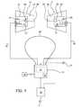
- the active hearing protection system shown in Fig. 1comprises a left ear earplug 10, a right ear earplug 12, a central unit 14, a boom microphone 16 and a remote control unit 18.
- the central unit 14is connected to a communication device 20.
- the hearing protection earplugs 10, 12have a hard shell with an elasticity from shore D85 to shore D65, which is customized, i.e. it has an outer shape according to the individual measured inner shape of the user's outer ear and ear canal.
- the hard shell 22may be manufactured by layer-by-layer laser sintering of a powder material, for example, polyamide powder or by laser stereo-lithography or photo-polymerization. An overview regarding such additive layer-by-layer build-up processes for manufacturing customized shells of hearing devices can be found, for example, in US 2003/0133583 A1 or US 6,533,062 B1 .
- the inner shape of the user's ear canal and outer earcan be measured, for example, by taking an impression which then undergoes laser scanning or by direct laser scanning of the ear.
- the hard shell 22is designed such that it provides for an acoustic attenuation of at least 10 dB averaged over the audible frequency range when worn by the user.
- the shell 22has a receptacle into which an active unit 24 can be inserted, preferably in a releasable manner.
- the shell 22is provided with a sound channel 26 through which the active unit 24 is acoustically connected to the ear canal.
- the active unit 24comprises a microphone 28 for capturing audio signals from ambient sound and a loudspeaker 30 for providing audio signals into the user's ear canal via the sound channel 26.
- Such earplugs comprising an active unitare described, for example, in EP 1 674 059 A1 .
- the central unit 14is to be worn at the user's body, e.g. by a loop 32 around the user's neck.
- the central unit 14comprises an audio signal processing unit 34 for receiving and processing the audio signals captured by the microphones 28 and for supplying the loudspeakers 30 with audio signals to be reproduced to the user's ear.
- the active units 24are connected to the central unit 14 via cable connections 36.
- the remote control unit 18is connected to the central unit 14 via a wireless link in order to serve as a user interface.
- the boom microphone 16may be connected to the central unit in order to supply audio signals captured from the user's voice (dashed lines in Figs. 1 and 2 ). Alternatively, it may be connected directly to the communication device 20.
- the communication device 20for example, may be a mobile phone or a FM radio device, such as a walkie-talkie. Usually the communication device 20 and the central unit 14 will be connected by wires, although connection by a wireless link is conceivable.
- audio signals captured from ambient sound by the microphones 28are provided, after processing in the audio signal processing unit 34, to the speakers 30 in order to provide sound impinging on the left ear to the left ear canal and sound impinging on the right ear to the right ear canal despite the acoustic attenuation provided by the shell 22 for relatively low sound pressure levels (for high sound pressure levels the gain will be progressively reduced in order to provide for a hearing protection function).
- audio signals received from the communication device 20are also to be provided to the user's ear via the central unit 14 and the speakers 30.
- the user's voicecan be captured by the boom microphone 16 and/or the microphones 28, 31 and will be supplied to the communication device 20.
- the central unit 14comprises an input 38 for the left ear microphone 28, an input 40 for the right ear microphone 28 and the audio signals from the communication device 20 and optionally an input 41 for the boom microphone 16.
- Each of these channelsis provided with a pre-amplifier 42 which preferably is adjustable.
- the pre-amplified signalis digitized in an analogue-to-digital converter 46 before it is supplied to the audio signal processing unit 34, which has at least two outputs for outputting corresponding the processed digital audio signals to a digital-to-analogue converter 48, with the respective analogue signal being provided to an output driver 50 driving the left ear speaker 30 and the right ear speaker 30, respectively.
- a third outputcomprising a digital-to-analogue converter 48 and an output driver 50 may be provided for supplying audio signals from the audio signal processing unit 34 to the communication device 20.
- the central unit 14comprises a further audio input 52 which is connected in the same manner as the input 40 to the communication device 20 and hence receives the same audio signals.
- the audio signals received at the input 52are provided to a low speed analogue-to-digital converter 54, with the digitized signals being provided to a detector 56 for detecting the presence of an audio signal from the communication device 20 at the audio input 52.
- the detector 56supplies a status signal to the audio signal processing unit 34 in order to select the audio signal processing mode depending on whether there is an audio signal from the communication device 20 or not.
- the detector 56also acts on the audio input 40 which can be switched between the microphone 28 and the communication device 20 depending on whether an audio signal from the communication device 20 is present or not.
- the audio signal processing unit 34operates in an "ambient mode" in which the right ear microphone 28 is selected as the audio signal source to the input 40 rather than the communication device 20.
- the audio signal processing unit 34primarily acts as a stereo device, i.e. the audio signals from the right ear microphone 28 are supplied essentially to the right ear speaker 30, and the audio signals from the left ear microphone 28 are essentially supplied to the left ear speaker 30.
- both channelsusually will be processed in the same manner, if the user is a normal hearing person. If, however, the user suffers from asymmetric hearing loss, also the audio signal processing in the "ambient mode" will be asymmetric in order to compensate for the hearing loss as far as possible.
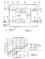
- Fig. 4an example of the acoustic gain model implemented in the audio signal processing unit 34 is shown, wherein the output free field sound pressure level (SPL FF) is given as a function of the input SPL FF.
- SPL FFoutput free field sound pressure level
- the shell 22provides for an attenuation of 30 dB.
- the curve with the diamondsrepresents the situation in which the gain is set to zero (i.e. no sound from the speakers 30). On this curve, the hearing protection system acts as a passive system.
- the curve with the squaresrepresents the situation in which the system has a "transparent" gain, i.e. below the knee point (which is set to 70 dBA) the user has the same sound feeling as if he was not wearing the earplugs 10, 12.
- Different gain settingsare applied below and above the knee point (which is set to 70 dBA in the example of Fig. 4 ). Below this knee point the gain is constant, resulting in a linear curve. Above the knee point, i.e. for higher input levels, the gain is progressively reduced so that the output level remains constant. For even higher input levels the system will act as a passive hearing protector.
- the systemalso comprises a manual volume control which is implemented on the central unit 14 or, alternatively or additionally, in the remote control unit 18.
- a manual volume controlwhich is implemented on the central unit 14 or, alternatively or additionally, in the remote control unit 18.
- the volume controlBy actuating the volume control, the value of the constant gain applied in the linear region below the knee point can be adjusted between a minimum value (circles in Fig. 4 ) and a maximum value (triangles in Fig. 4 ).
- the maximum output free field sound pressure levelis limited to 80 dBA SPL FF in the example of Fig. 4 .
- 85 dBA SPL FFcorrespond to the maximum noise level tolerable for 8 hours a day according to Directive 2003/10/EC. Since the open ear gain (OEG) is around 10 dB, the sound pressure level in the ear canal is around 10 dB higher than the free-field values given in Fig. 4 .
- Fig. 4the gain model is shown for one frequency.
- the gain model to be applied by the audio signal processing unit 34may be frequency-dependant in order to compensate for the frequency-dependency of the acoustic attenuation provided by the shell 22 and/or a hearing loss of the user.
- the central unit 14may comprise manual user interfaces such as e.g. on/off, audio signal processing mode (program) change, push-to-talk (PTT), call accept/reject or voice dialing. These manual control interfaces are designated by 35 in Figs. 1 and 2 . The same commands or a subset thereof may be provided on the remote control unit 18.
- manual user interfacessuch as e.g. on/off, audio signal processing mode (program) change, push-to-talk (PTT), call accept/reject or voice dialing.
- the acoustic gain modelmay be automatically selected according to the result of an auditory scene analysis based on the audio signals provided by the microphones 28.
- the central unit 14will switch into a "communication mode" in which the input from the right ear microphone 28 is replaced by the audio signals provided by the communication device 20.
- a different gain modelnow is applied to that channel to which the audio signals from the communication device 20 are provided to.
- the maximum output free field sound pressure levelmay be shifted to higher values, for example in such a manner that an output level of 100 dBA SPL FF is allowed (rather than 80 dBA SPL FF allowable for the channel of the left ear).
- This level limiting function in both channelsis labelled “LIM" ("limiter")in Fig. 3 .
- the volume controlwill act only on the "ambient channel", i.e. the left ear microphone channel. After having undergone respective audio signal processing, the two channels may be combined and then may be supplied as a mono signal to both loudspeakers 30.
- FIG. 3Such an example of operation of the system in the communication mode is schematically shown in Fig. 3 (the right ear microphone 28 is omitted in Fig. 3 , since it is blocked by action of the detector 56 on the input 40).
- a mixture of audio signals representative of the ambient sound as captured by the left ear microphone 28 and the audio signals provided by the communication device 20is provided to both ears.
- the usercan adjust the relative level of the "ambient channel” and the "communication channel” by actuating the volume control on the central unit 14 or via the remote control unit 18, which in the communication mode acts only on the "ambient channel".
- the volume of the communication channelmay be adjusted on the communication device 20.
- the "communication channel”may undergo some speech enhancement filtering in order to improve intelligibility of the speech. Enhancement of the intelligibility of the voice in the "communication channel” can be achieved, for example, by reducing the audio band width and/or emphasizing speech frequencies (300 Hz to 3.4 kHz). However, such filtering also my be applied to the "ambient channel” or to both channels in the ambient mode if speech signals are received via the microphones 28. The decision that speech is present may be made by performing auditory scene analysis in the audio signal processing unit 34 based on the audio signals captured by the microphones 28.
- the audio signals from the communication device 20may be mixed to at least one of the audio signals captured by the left ear microphone 28 and the right ear microphone 28, with, as in the ambient mode, the audio signals captured by the left ear microphone 28 being provided to the left ear speaker and the audio signals from the right ear microphone 28 being provided to the right ear speaker 30.
- the mixing ratiomay be different for the two channels.
- the central unitwould be equipped with a further fast analogue-to-digital converter, so that the audio signals from the communication device 20 could be processed in parallel to the audio signals from the left ear microphone 28 and the right ear microphone 28.
- the interface between the communication device 20 and the central unit 14is bidirectional so that not only audio signals can be supplied from the communication device 20 to the central unit 14 but also audio signals and/or command signals can be sent from the central unit 14 to the communication device 20.
- the user's voicemay be captured by the boom microphone 16 and/or the microphones 28 in order to be supplied to the communication device 20 via the third output (dashed lines).
- the boom microphone 16may be omitted if the central unit 14 is capable of performing blind source separation (BSS) on the audio signals provided by the microphones 28, 31 in order to separate the user's voice from background noise.
- BSSblind source separation
- the inner microphone 31is required on only one of both sides.
- each active unit 24 of the earplugs 10, 12in this case may include a second microphone 31 which is acoustically oriented towards the ear canal in order to capture primarily the user's voice, whereas the microphone 28 is acoustically oriented towards ambience in order to capture primarily ambient sound.
- one or two microphones 31 on the right and/or the left sidemay pick up the user's voice transferred by bone conduction to the ear canal (in-ear voice pickup).
- the central unit 14may be capable of performing acoustic beamforming on the audio signals captured by the microphones 28 in order to separate the user's voice from ambient sound/background noise.
- the central unit 14 and/or remote control unit 18preferably comprises a PTT (Push to Talk) element operable by the user to control transmission of audio signals, representing the user's voice, via the communication device 20.
- PTTPush to Talk
- the central unit 14 and/or remote control unit 18also may comprise a call accept/call reject element and a voice dialling activation element for the event that the communication device 20 is a mobile phone.
- the communication device 20also may serve to supply power to the central unit 14.
- the central unit 14may be provided with a primary or rechargeable battery (not shown in Figs. 1 to 3 ).
- the audio signals representing the user's voice captured by the microphones 28 and/or the boom microphone 16may be supplied not only to the communication device 20 but also to some extent to the right ear and left ear speaker 30 in order to reduce the occlusion effect caused by the acoustic attenuation of the shell 22.
- the central unit 14may be capable of user preference learning in order to learn and store the preferred manual settings by the user.
- the audio signal processing unit 34is realized as a single digital signal processing (DSP) chip.
- DSPdigital signal processing
- the central unit 14also may comprise a noise dosimeter functionality, with the sound exposure of the user being estimated from the level of the audio signals captured by the left ear and right ear microphones 28 or 31, which is integrated over a given time period.
- the central unit 14may comprise an alarm function wherein the user is alerted via at least one of the speakers 30 when a given maximum noise dose has been reached.
- the central unit 14may comprise a protection function wherein the gain applied in the audio signal processing unit 34 is reduced when a given maximum noise dose has been reached.
Landscapes
- Health & Medical Sciences (AREA)
- Life Sciences & Earth Sciences (AREA)
- Engineering & Computer Science (AREA)
- Acoustics & Sound (AREA)
- Physics & Mathematics (AREA)
- Psychology (AREA)
- Biophysics (AREA)
- Otolaryngology (AREA)
- Biomedical Technology (AREA)
- Heart & Thoracic Surgery (AREA)
- Vascular Medicine (AREA)
- Animal Behavior & Ethology (AREA)
- General Health & Medical Sciences (AREA)
- Public Health (AREA)
- Veterinary Medicine (AREA)
- Signal Processing (AREA)
- Headphones And Earphones (AREA)
Description
- The present invention relates to an active haring protection system comprising a left and a right earplug, each being adapted for providing for an acoustic attenuation of at least 10 dB averaged over the audible frequency range and comprising an active unit with a microphone for capturing audio signals from ambient sound and a loudspeaker.
US 4,677,678 relates to a hearing protection system comprising two earmuffs or earplugs comprising each a microphone and a speaker. The system comprises two audio channels sharing a common sound level limiting unit.US 2002/0080979 A1 relates to a hearing protection system comprising two earplugs into which an active unit comprising each a microphone and a speaker is inserted. The gain as a function of the sound input level is a three-segment piece-wise linear function including a first section providing maximum expansion up to a first knee point for maximum noise reduction, a second section providing less expansion up to a second knee point for less noise reduction, and a third section providing minimum or no expansion for input signals with high signal-to-noise-ratio (SNR) to minimise distortion.EP 1 674 061 A1EP 1 674 057 A1EP 1 615 468 A1DE 101 17 705 A1 relate to hearing protection systems comprising a microphone, an audio signal processing unit and a speaker at each ear, wherein in addition a wireless interface for an external audio source, such as a mobile phone or a remote active hearing protection system used by another person, is provided.- Hearing protection systems provided with an interface for wireless audio input from a remote audio signal source, but not having microphones at ear level, are known, for example, from
EP 1 674 059 A1GB 2 373 951 AUS 5,426,719 andUS 2003/0059071 A1 . EP 1 653 773 A2EP 1 443 803 A2US 5,721,783 relates to a hearing instrument comprising two ear-pieces with a microphone and a speaker and a remote audio signal processing unit wirelessly connected to the ear-pieces. Audio signals from a phone can be provided via the remote audio signal processing unit to the ear-pieces. A switch is provided for switching between the microphone signals and the phone signals as the audio input to audio signal processing unit. The system may comprise active noise cancelling capability.US 2004/0136522 A1 relates to a headset which comprises at each ear an active noise reduction (ANR) arrangement comprising a microphone and a speaker for generating anti-noise. Further, the headset comprises at each ear a communication loudspeaker provided with audio signals from a primary communication device and/or a secondary communication device. In addition, the headset comprises a boom microphone whose audio signal may be provided, after pre-amplification in a controller, to the primary and secondary communication device. The controller, which acts a central unit utilized by both sides of the headset, comprises a device detector, which senses the presence of the secondary communication unit, and a communication priority module for weighting of the audio signals from the primary communication device and the secondary communication device.- It is an object of the invention to provide for an active hearing protection system which provides for a particularly comfortable and flexible communication function. It is a further object to provide for a corresponding method for providing hearing protection to a user.
- According to the invention, these objects are achieved by an active hearing protection system as defined in
claim 1 and a method as defined in claim 15, respectively. The invention is beneficial in that, by providing for a central unit having a digital audio signal processing unit having at least two channels and by automatically controlling the audio signal processing unit depending on whether the presence of an audio signal at the audio input of the audio signal processing unit has been detected or not, external audio signals can be combined for communication purposes in a particularly comfortable and flexible manner with the audio signal captured by the microphones of the system. - Preferred embodiments of the invention are defined in the dependent claims.
- In the following, examples of the invention will be illustrated by reference to the attached drawings, wherein:
- Fig. 1
- is a schematic view of an example of an active hearing protection system according to the invention;
- Fig. 2
- is a block diagram of the electronic components of the system of
Fig. 1 ; - Fig. 3
- is a block diagram of the system wherein operation in the communication mode is illustrated; and
- Fig. 4
- is a diagram showing an example of the acoustic gain model of the system.
- The active hearing protection system shown in
Fig. 1 comprises aleft ear earplug 10, aright ear earplug 12, acentral unit 14, a boom microphone 16 and aremote control unit 18. Thecentral unit 14 is connected to acommunication device 20. - Preferably the
hearing protection earplugs hard shell 22 may be manufactured by layer-by-layer laser sintering of a powder material, for example, polyamide powder or by laser stereo-lithography or photo-polymerization. An overview regarding such additive layer-by-layer build-up processes for manufacturing customized shells of hearing devices can be found, for example, inUS 2003/0133583 A1 orUS 6,533,062 B1 . The inner shape of the user's ear canal and outer ear can be measured, for example, by taking an impression which then undergoes laser scanning or by direct laser scanning of the ear. Preferably thehard shell 22 is designed such that it provides for an acoustic attenuation of at least 10 dB averaged over the audible frequency range when worn by the user. - The
shell 22 has a receptacle into which anactive unit 24 can be inserted, preferably in a releasable manner. Theshell 22 is provided with asound channel 26 through which theactive unit 24 is acoustically connected to the ear canal. Theactive unit 24 comprises amicrophone 28 for capturing audio signals from ambient sound and aloudspeaker 30 for providing audio signals into the user's ear canal via thesound channel 26. Such earplugs comprising an active unit are described, for example, inEP 1 674 059 A1 - The
central unit 14 is to be worn at the user's body, e.g. by aloop 32 around the user's neck. Thecentral unit 14 comprises an audiosignal processing unit 34 for receiving and processing the audio signals captured by themicrophones 28 and for supplying theloudspeakers 30 with audio signals to be reproduced to the user's ear. To this end, theactive units 24 are connected to thecentral unit 14 viacable connections 36. Theremote control unit 18 is connected to thecentral unit 14 via a wireless link in order to serve as a user interface. - The boom microphone 16 may be connected to the central unit in order to supply audio signals captured from the user's voice (dashed lines in
Figs. 1 and2 ). Alternatively, it may be connected directly to thecommunication device 20. Thecommunication device 20, for example, may be a mobile phone or a FM radio device, such as a walkie-talkie. Usually thecommunication device 20 and thecentral unit 14 will be connected by wires, although connection by a wireless link is conceivable. - In order to act as an active hearing protection system, audio signals captured from ambient sound by the
microphones 28 are provided, after processing in the audiosignal processing unit 34, to thespeakers 30 in order to provide sound impinging on the left ear to the left ear canal and sound impinging on the right ear to the right ear canal despite the acoustic attenuation provided by theshell 22 for relatively low sound pressure levels (for high sound pressure levels the gain will be progressively reduced in order to provide for a hearing protection function). Further, audio signals received from thecommunication device 20 are also to be provided to the user's ear via thecentral unit 14 and thespeakers 30. In addition, if bidirectional communication is desired, the user's voice can be captured by the boom microphone 16 and/or themicrophones communication device 20. - The structure and the functionality of the
central unit 14 will be explained in more detail by reference toFigs. 2 to 4 . Thecentral unit 14 comprises aninput 38 for theleft ear microphone 28, aninput 40 for theright ear microphone 28 and the audio signals from thecommunication device 20 and optionally aninput 41 for the boom microphone 16. Each of these channels is provided with a pre-amplifier 42 which preferably is adjustable. The pre-amplified signal is digitized in an analogue-to-digital converter 46 before it is supplied to the audiosignal processing unit 34, which has at least two outputs for outputting corresponding the processed digital audio signals to a digital-to-analogue converter 48, with the respective analogue signal being provided to anoutput driver 50 driving theleft ear speaker 30 and theright ear speaker 30, respectively. A third output comprising a digital-to-analogue converter 48 and anoutput driver 50 may be provided for supplying audio signals from the audiosignal processing unit 34 to thecommunication device 20. - The
central unit 14 comprises afurther audio input 52 which is connected in the same manner as theinput 40 to thecommunication device 20 and hence receives the same audio signals. The audio signals received at theinput 52 are provided to a low speed analogue-to-digital converter 54, with the digitized signals being provided to adetector 56 for detecting the presence of an audio signal from thecommunication device 20 at theaudio input 52. On the one hand, thedetector 56 supplies a status signal to the audiosignal processing unit 34 in order to select the audio signal processing mode depending on whether there is an audio signal from thecommunication device 20 or not. On the other hand, thedetector 56 also acts on theaudio input 40 which can be switched between themicrophone 28 and thecommunication device 20 depending on whether an audio signal from thecommunication device 20 is present or not. - If no audio signal from the
communication device 20 is detected by thedetector 56, the audiosignal processing unit 34 operates in an "ambient mode" in which theright ear microphone 28 is selected as the audio signal source to theinput 40 rather than thecommunication device 20. In the ambient mode the audiosignal processing unit 34 primarily acts as a stereo device, i.e. the audio signals from theright ear microphone 28 are supplied essentially to theright ear speaker 30, and the audio signals from theleft ear microphone 28 are essentially supplied to theleft ear speaker 30. However, there may be some transfer of audio signals between the two channels in order to enable binaural audio signal processing. Examples of binaural audio signal processing can be found inEP 1 320 281 A2WO 99/43185 US 2004/02 52852 A1 . Apart from such binaural processing, both channels usually will be processed in the same manner, if the user is a normal hearing person. If, however, the user suffers from asymmetric hearing loss, also the audio signal processing in the "ambient mode" will be asymmetric in order to compensate for the hearing loss as far as possible. - In
Fig. 4 an example of the acoustic gain model implemented in the audiosignal processing unit 34 is shown, wherein the output free field sound pressure level (SPL FF) is given as a function of the input SPL FF. In the example shown inFig. 4 it is assumed that theshell 22 provides for an attenuation of 30 dB. The curve with the diamonds represents the situation in which the gain is set to zero (i.e. no sound from the speakers 30). On this curve, the hearing protection system acts as a passive system. - The curve with the squares represents the situation in which the system has a "transparent" gain, i.e. below the knee point (which is set to 70 dBA) the user has the same sound feeling as if he was not wearing the
earplugs Fig. 4 ). Below this knee point the gain is constant, resulting in a linear curve. Above the knee point, i.e. for higher input levels, the gain is progressively reduced so that the output level remains constant. For even higher input levels the system will act as a passive hearing protector. - The system also comprises a manual volume control which is implemented on the
central unit 14 or, alternatively or additionally, in theremote control unit 18. By actuating the volume control, the value of the constant gain applied in the linear region below the knee point can be adjusted between a minimum value (circles inFig. 4 ) and a maximum value (triangles inFig. 4 ). When the maximum gain is applied, the maximum output free field sound pressure level is limited to 80 dBA SPL FF in the example ofFig. 4 . 85 dBA SPL FF correspond to the maximum noise level tolerable for 8 hours a day according to Directive 2003/10/EC. Since the open ear gain (OEG) is around 10 dB, the sound pressure level in the ear canal is around 10 dB higher than the free-field values given inFig. 4 . - In
Fig. 4 the gain model is shown for one frequency. The gain model to be applied by the audiosignal processing unit 34 may be frequency-dependant in order to compensate for the frequency-dependency of the acoustic attenuation provided by theshell 22 and/or a hearing loss of the user. - Beyond the volume control interface, the
central unit 14 may comprise manual user interfaces such as e.g. on/off, audio signal processing mode (program) change, push-to-talk (PTT), call accept/reject or voice dialing. These manual control interfaces are designated by 35 inFigs. 1 and2 . The same commands or a subset thereof may be provided on theremote control unit 18. - The acoustic gain model may be automatically selected according to the result of an auditory scene analysis based on the audio signals provided by the
microphones 28. - According to an example not covered by the present invention, once an audio signal from the
communication device 20 is detected by thedetector 56, thecentral unit 14 will switch into a "communication mode" in which the input from theright ear microphone 28 is replaced by the audio signals provided by thecommunication device 20. Whereas in the ambient mode - apart from compensation of an asymmetric hearing loss - usually the same gain model is applied to both channels, in the communication mode preferably a different gain model now is applied to that channel to which the audio signals from thecommunication device 20 are provided to. In this "communication channel" the maximum output free field sound pressure level may be shifted to higher values, for example in such a manner that an output level of 100 dBA SPL FF is allowed (rather than 80 dBA SPL FF allowable for the channel of the left ear). This level limiting function in both channels is labelled "LIM" ("limiter")inFig. 3 . In the communication mode the volume control will act only on the "ambient channel", i.e. the left ear microphone channel. After having undergone respective audio signal processing, the two channels may be combined and then may be supplied as a mono signal to bothloudspeakers 30. - Such an example of operation of the system in the communication mode is schematically shown in
Fig. 3 (theright ear microphone 28 is omitted inFig. 3 , since it is blocked by action of thedetector 56 on the input 40). According to this example in the communication mode a mixture of audio signals representative of the ambient sound as captured by theleft ear microphone 28 and the audio signals provided by thecommunication device 20 is provided to both ears. The user can adjust the relative level of the "ambient channel" and the "communication channel" by actuating the volume control on thecentral unit 14 or via theremote control unit 18, which in the communication mode acts only on the "ambient channel". - The volume of the communication channel may be adjusted on the
communication device 20. - In case that the audio signals provided by the
communication device 20 are speech signals the "communication channel" may undergo some speech enhancement filtering in order to improve intelligibility of the speech. Enhancement of the intelligibility of the voice in the "communication channel" can be achieved, for example, by reducing the audio band width and/or emphasizing speech frequencies (300 Hz to 3.4 kHz). However, such filtering also my be applied to the "ambient channel" or to both channels in the ambient mode if speech signals are received via themicrophones 28. The decision that speech is present may be made by performing auditory scene analysis in the audiosignal processing unit 34 based on the audio signals captured by themicrophones 28. - According to the invention, in the communication mode the audio signals from the
communication device 20 may be mixed to at least one of the audio signals captured by theleft ear microphone 28 and theright ear microphone 28, with, as in the ambient mode, the audio signals captured by theleft ear microphone 28 being provided to the left ear speaker and the audio signals from theright ear microphone 28 being provided to theright ear speaker 30. The mixing ratio may be different for the two channels. In this case the central unit would be equipped with a further fast analogue-to-digital converter, so that the audio signals from thecommunication device 20 could be processed in parallel to the audio signals from theleft ear microphone 28 and theright ear microphone 28. - Preferably the interface between the
communication device 20 and thecentral unit 14 is bidirectional so that not only audio signals can be supplied from thecommunication device 20 to thecentral unit 14 but also audio signals and/or command signals can be sent from thecentral unit 14 to thecommunication device 20. For example, the user's voice may be captured by the boom microphone 16 and/or themicrophones 28 in order to be supplied to thecommunication device 20 via the third output (dashed lines). - The boom microphone 16 may be omitted if the
central unit 14 is capable of performing blind source separation (BSS) on the audio signals provided by themicrophones inner microphone 31 is required on only one of both sides. Preferably, eachactive unit 24 of theearplugs second microphone 31 which is acoustically oriented towards the ear canal in order to capture primarily the user's voice, whereas themicrophone 28 is acoustically oriented towards ambience in order to capture primarily ambient sound. - Alternatively, one or two
microphones 31 on the right and/or the left side may pick up the user's voice transferred by bone conduction to the ear canal (in-ear voice pickup). - Alternatively or in addition, the
central unit 14 may be capable of performing acoustic beamforming on the audio signals captured by themicrophones 28 in order to separate the user's voice from ambient sound/background noise. - The
central unit 14 and/orremote control unit 18 preferably comprises a PTT (Push to Talk) element operable by the user to control transmission of audio signals, representing the user's voice, via thecommunication device 20. - The
central unit 14 and/orremote control unit 18 also may comprise a call accept/call reject element and a voice dialling activation element for the event that thecommunication device 20 is a mobile phone. - The
communication device 20 also may serve to supply power to thecentral unit 14. Alternatively, thecentral unit 14 may be provided with a primary or rechargeable battery (not shown inFigs. 1 to 3 ). - The audio signals representing the user's voice captured by the
microphones 28 and/or the boom microphone 16 may be supplied not only to thecommunication device 20 but also to some extent to the right ear and leftear speaker 30 in order to reduce the occlusion effect caused by the acoustic attenuation of theshell 22. - The
central unit 14 may be capable of user preference learning in order to learn and store the preferred manual settings by the user. - Preferably, the audio
signal processing unit 34 is realized as a single digital signal processing (DSP) chip. - The
central unit 14 also may comprise a noise dosimeter functionality, with the sound exposure of the user being estimated from the level of the audio signals captured by the left ear andright ear microphones central unit 14 may comprise an alarm function wherein the user is alerted via at least one of thespeakers 30 when a given maximum noise dose has been reached. Alternatively or in addition, thecentral unit 14 may comprise a protection function wherein the gain applied in the audiosignal processing unit 34 is reduced when a given maximum noise dose has been reached.
Claims (15)
- An active hearing protecting system comprising a right earplug (10) to be worn at least in part in the right ear canal of a user and a left earplug (12) to be worn at least in part in the left ear canal of the user and a central unit (14) to be worn at the user's body and comprising a digital audio signal processing unit (34) which has at least two channels and which can be connected via an audio input (40) to an external audio signal source (20),
wherein each earplug (10, 12) is adapted for providing for an acoustic attenuation of at least 10 dB averaged over the audible frequency range and comprises an active unit (24) comprising a microphone (28) for capturing audio signals from ambient sound and a loudspeaker (30) which are connected to the audio signal processing unit (34),
wherein the central unit comprises a detector (56) for detecting the presence of an audio signal at the audio input (40, 52),
and wherein the central unit (14) is adapted to control the audio signal processing unit (34) in such a manner that, during times when no presence of an audio signal at the audio input (40, 52) is detected, the audio signal processing unit (34) is operated in an ambient mode in which the audio signals captured by the left ear microphone (28) are provided essentially to the left ear loudspeaker (30) and the audio signals captured by the right ear microphone (28) are provided essentially to the right ear loudspeaker (30), and during times when the presence of an audio signal at the audio input (40, 52) is detected, the audio signal processing unit (34) is operated in a communication mode in which the audio signals captured by the left ear microphone (28) are provided to the left ear loudspeaker (30) and the audio signals captured by the right ear microphone (28) are provided to the right ear loudspeaker (30), wherein the audio signals received via the audio input (40, 52) are mixed with at least one of the audio signals captured by the left ear microphone (28) and the audio signals captured by the right ear microphone (28) in order to be provided to at least one of the left ear (30) loudspeaker and the right ear loudspeaker (30), and wherein at least one parameter used for audio signal processing in the audio signal processing unit (34) is different for the ambient mode and the communication mode for at least one of the channels, and wherein the parameter is the gain as a function of the input level. - The system of claim 1, wherein the mixing ratio is different for mixing with the audio signals captured by the left ear microphone (28) and for mixing with the audio signals captured by the right ear microphone (28).
- The system of one of the preceding claims, wherein both in the ambient mode and in the communication mode for the two channels of the audio signal processing unit (34) the gain is progressively reduced above a given threshold value of the input level, wherein the gain is essentially independent of the input level for input levels below the threshold value, wherein for input levels below the threshold value the gain of at least one of the channels is adjustable by a manual volume control (18), wherein in the ambient mode the gain of both channels is adjustable in parallel by the manual volume control (18), wherein in the communication mode only the gain of that channel carrying primarily the audio signals captured by at least one of the left ear microphone (28) and right ear microphone (28) is adjustable by the manual volume control (18), wherein in the communication mode the maximum acoustic output level is different for the two channels, wherein in the ambient mode the gain function of the audio signal processing unit (34) can be selected manually or is automatically selected based on the result of an auditory scene analysis, wherein the central unit (14) comprises a bidirectional interface to a wireless communication device (20), which communication device is for providing audio signals to the audio input (40, 52), wherein the system comprises means (16, 28) for capturing audio signals to be supplied to the communication device (20) and wherein the system comprises a remote control unit (18) adapted for manual control of the communication device (20), wherein the central unit (14) comprises a bidirectional interface to a wireless communication device (20), which communication device is for providing audio signals to the audio input (40, 52), wherein the system comprises means (16, 28) for capturing audio signals to be supplied to the communication device (20) and wherein the central unit (14) comprises a user interface for manual control of the communication device (20), and wherein the bidirectional interface is wireless.
- The system of claim 3, wherein the means for capturing audio signals is a boom microphone (16) which is to be worn by the user to capture the user's voice and which is electrically connected to the communication device directly or via said interface.
- The system of claim 3, wherein the means for capturing audio signals is at least one of the left ear microphone (28) and the right ear microphone (28) and/or at least one inner microphone (31) acoustically oriented inwardly towards the ear canal.
- The system of claim 5, wherein a BSS unit is included in the audio signal processing unit (34) in order to have the audio signals captured by at least one of the left ear microphone (28) and the right ear microphone (28) and/or at least one inner microphone (31) undergo a BSS algorithm in order to separate the user's voice from ambient sound.
- The system of claim 5, wherein the audio signal processing unit (34) is capable of performing acoustic beamforming on the audio signals captured by the left ear microphone (28) and the right ear microphone (28) in order to separate the user's voice from ambient sound, and wherein the remote control unit (18) is a handheld unit connected to the central unit (34) by a wireless link.
- The system of claim 3, wherein the central unit (14) and/or the remote control unit (18) comprises a Push-to-talk element (35) for controlling transmission of the audio signals supplied by the audio signal capturing means (16, 28, 31) by the communication device (20).
- The system of claim 3, wherein the remote control unit (18) comprises a volume control element for controlling the gain applied by the audio signal processing unit (34).
- The system of claim 3, wherein the communication device (20) is a mobile phone, and wherein the remote control unit (18) comprises a call accept / call reject element and a voice dialing activation element.
- The system of claim 3, wherein the communication device (20) is a mobile phone, and wherein the central unit (14) comprises a call accept / call reject element and a voice dialing activation element, wherein power is supplied from the communication device (20) to the central unit (14) via the bidirectional interface, wherein the audio signal processing unit (34) in the ambient mode is adapted to enhance by filtering the user's voice in the audio signals captured by the left ear microphone (28) and the right ear microphone (28) or in the audio signals captured by a boom microphone (16), with the filtered audio signals being provided to the right ear and left ear loudspeaker (30) in order to reduce occlusion effect, wherein the central unit (14) is capable of user preference learning in order to learn and store the preferred manual settings by the user, wherein the audio signal processing unit (34) is a single DSP chip, wherein the central unit (14) comprises a noise dosimeter functionality, with the sound exposure of the user being estimated from the level of the audio signals captured by the left ear and/or right ear microphone (28) and/or by at least one inner microphone (31) acoustically oriented inwardly towards the ear canal and integrated over a given time period, wherein the central unit (14) comprises an alarm function wherein the user is alerted via at least one of the left ear and right car (30) loudspeaker when a given maximum noise dose has been reached, wherein the central unit (14) comprises a user protection function wherein the gain applied in the audio signal processing unit (34) is reduced when a given maximum noise dose has been reached, wherein the gain applied by the audio signal processing unit (34) in at least one of the ambient mode and the communication mode is frequency-dependent in order to compensate for at least one of the frequency dependence of the acoustic attenuation provided by the earplugs (10, 12) and a hearing loss of the user, and wherein the gain applied by the audio signal processing unit (34) in at least one of the ambient mode and the communication mode is frequency-dependent in order to enhance speech intelligibility of the audio signals received via the audio input (40, 52).
- The system of one of the preceding claims, wherein in the ambient mode one of a plurality of audio signal processing modes of the audio signal processing unit (34) is automatically selected according to the result of an auditory scene analysis.
- The system of one of the claims 1 to 11, wherein in the ambient mode one of a plurality of audio signal processing modes of the audio signal processing unit (34) can be manually selected on the central unit (14) or via a remote control unit (18).
- The system of one of the preceding claims, wherein each earplug (10, 12) comprises a customized shell (22) into which the active unit (24) is detachably inserted.
- A method for providing hearing protecting to user, comprising:wearing a right earplug (10) comprising a microphone (28) and a loudspeaker (30) at least in part in the right ear canal and a left earplug (12) comprising a microphone (28) and a loudspeaker (30) at least in part in the left ear canal in such a manner that each earplug provides for an acoustic attenuation of at least 10 dB averaged over the audible frequency range;wearing a central unit (14) comprising a digital audio signal processing unit (34) which has at least two channels at the user's body;connecting an external audio signal source (20) via an audio input (40, 52) to the central unit (14);detecting whether an audio signal is present at the audio input (40, 52) or not; andcontrolling the audio signal processing unit (34) in such a manner that, during times when no presence of an audio signal at the audio input (40, 52) is detected, the audio signal processing unit (34) is operated in an ambient mode in which the audio signals captured by the left ear microphone (28) are provided essentially to the left ear loudspeaker (30) and the audio signals captured by the right ear microphone (28) are provided essentially to the right ear loudspeaker (30), and during times when the presence of an audio signal at the audio input (40, 52) is detected, the audio signal processing unit (34) is operated in a communication mode in which the audio signals captured by the left ear microphone (28) are provided to the left ear loudspeaker (30) and the audio signals captured by the right ear microphone (28) are provided to the right ear loudspeaker (30), and wherein the audio signals received via the audio input (40, 52) are mixed with at least one of the audio signals captured by the left ear microphone (28) and the audio signals captured by the right ear microphone (28) in order to be provided to at least one of the left ear loudspeaker (30) and the right ear loudspeaker (30), and wherein at least one parameter used for audio signal processing in the audio signal processing unit (34) is different for the ambient mode and the communication mode for at least one of the channels, and wherein the parameter is the gain as a function of the input level.
Applications Claiming Priority (1)
| Application Number | Priority Date | Filing Date | Title |
|---|---|---|---|
| PCT/EP2006/012201WO2007082579A2 (en) | 2006-12-18 | 2006-12-18 | Active hearing protection system |
Publications (2)
| Publication Number | Publication Date |
|---|---|
| EP2127467A2 EP2127467A2 (en) | 2009-12-02 |
| EP2127467B1true EP2127467B1 (en) | 2015-10-28 |
Family
ID=38287971
Family Applications (1)
| Application Number | Title | Priority Date | Filing Date |
|---|---|---|---|
| EP06841011.7AActiveEP2127467B1 (en) | 2006-12-18 | 2006-12-18 | Active hearing protection system |
Country Status (4)
| Country | Link |
|---|---|
| US (1) | US20100119077A1 (en) |
| EP (1) | EP2127467B1 (en) |
| DK (1) | DK2127467T3 (en) |
| WO (1) | WO2007082579A2 (en) |
Families Citing this family (64)
| Publication number | Priority date | Publication date | Assignee | Title |
|---|---|---|---|---|
| WO2007147077A2 (en) | 2006-06-14 | 2007-12-21 | Personics Holdings Inc. | Earguard monitoring system |
| EP2044804A4 (en) | 2006-07-08 | 2013-12-18 | Personics Holdings Inc | PERSONAL HEARING AID AND METHOD |
| JP5530720B2 (en) | 2007-02-26 | 2014-06-25 | ドルビー ラボラトリーズ ライセンシング コーポレイション | Speech enhancement method, apparatus, and computer-readable recording medium for entertainment audio |
| US11750965B2 (en) | 2007-03-07 | 2023-09-05 | Staton Techiya, Llc | Acoustic dampening compensation system |
| WO2008124786A2 (en) | 2007-04-09 | 2008-10-16 | Personics Holdings Inc. | Always on headwear recording system |
| US11217237B2 (en) | 2008-04-14 | 2022-01-04 | Staton Techiya, Llc | Method and device for voice operated control |
| US8788077B2 (en) | 2007-04-27 | 2014-07-22 | Personics Holdings, LLC. | Designer control devices |
| US11683643B2 (en) | 2007-05-04 | 2023-06-20 | Staton Techiya Llc | Method and device for in ear canal echo suppression |
| US11856375B2 (en) | 2007-05-04 | 2023-12-26 | Staton Techiya Llc | Method and device for in-ear echo suppression |
| US10009677B2 (en) | 2007-07-09 | 2018-06-26 | Staton Techiya, Llc | Methods and mechanisms for inflation |
| EP2206358B1 (en)* | 2007-09-24 | 2014-07-30 | Sound Innovations, LLC | In-ear digital electronic noise cancelling and communication device |
| WO2009049645A1 (en) | 2007-10-16 | 2009-04-23 | Phonak Ag | Method and system for wireless hearing assistance |
| EP2206362B1 (en) | 2007-10-16 | 2014-01-08 | Phonak AG | Method and system for wireless hearing assistance |
| US8600067B2 (en) | 2008-09-19 | 2013-12-03 | Personics Holdings Inc. | Acoustic sealing analysis system |
| US9129291B2 (en) | 2008-09-22 | 2015-09-08 | Personics Holdings, Llc | Personalized sound management and method |
| WO2010040370A1 (en)* | 2008-10-09 | 2010-04-15 | Phonak Ag | System for picking-up a user's voice |
| EP2392085B1 (en)* | 2009-01-28 | 2021-06-23 | Samsung Electronics Co., Ltd. | Portable terminal and sound detector, which both communicate using body area network, and data controlling method therefor |
| WO2009050306A2 (en)* | 2009-01-30 | 2009-04-23 | Phonak Ag | System and method for providing active hearing protection to a user |
| US8379872B2 (en)* | 2009-06-01 | 2013-02-19 | Red Tail Hawk Corporation | Talk-through listening device channel switching |
| US8666102B2 (en) | 2009-06-12 | 2014-03-04 | Phonak Ag | Hearing system comprising an earpiece |
| WO2011161487A1 (en)* | 2010-06-21 | 2011-12-29 | Nokia Corporation | Apparatus, method and computer program for adjustable noise cancellation |
| US9025782B2 (en)* | 2010-07-26 | 2015-05-05 | Qualcomm Incorporated | Systems, methods, apparatus, and computer-readable media for multi-microphone location-selective processing |
| EP2617204A2 (en) | 2010-09-14 | 2013-07-24 | Phonak AG | Dynamic hearing protection method and device |
| US20140010378A1 (en)* | 2010-12-01 | 2014-01-09 | Jérémie Voix | Advanced communication earpiece device and method |
| US12349097B2 (en) | 2010-12-30 | 2025-07-01 | St Famtech, Llc | Information processing using a population of data acquisition devices |
| US20130013302A1 (en) | 2011-07-08 | 2013-01-10 | Roger Roberts | Audio input device |
| EP2782533B1 (en) | 2011-11-23 | 2015-09-30 | Sonova AG | Hearing protection earpiece |
| US9288570B2 (en) | 2013-08-27 | 2016-03-15 | Bose Corporation | Assisting conversation while listening to audio |
| US9190043B2 (en)* | 2013-08-27 | 2015-11-17 | Bose Corporation | Assisting conversation in noisy environments |
| US9167082B2 (en) | 2013-09-22 | 2015-10-20 | Steven Wayne Goldstein | Methods and systems for voice augmented caller ID / ring tone alias |
| EP4531436A1 (en) | 2013-11-07 | 2025-04-02 | Oticon A/s | A binaural hearing assistance system comprising two wireless interfaces |
| US9445177B2 (en)* | 2013-11-18 | 2016-09-13 | 3M Innovative Properties Company | Hearing device tether with acoustic decoupling section |
| EP2882203A1 (en) | 2013-12-06 | 2015-06-10 | Oticon A/s | Hearing aid device for hands free communication |
| US9478229B2 (en) | 2013-12-10 | 2016-10-25 | Massachusetts Institute Of Technology | Methods and apparatus for recording impulsive sounds |
| US10043534B2 (en) | 2013-12-23 | 2018-08-07 | Staton Techiya, Llc | Method and device for spectral expansion for an audio signal |
| US10148240B2 (en)* | 2014-03-26 | 2018-12-04 | Nokia Technologies Oy | Method and apparatus for sound playback control |
| EP2991379B1 (en) | 2014-08-28 | 2017-05-17 | Sivantos Pte. Ltd. | Method and device for improved perception of own voice |
| US10163453B2 (en) | 2014-10-24 | 2018-12-25 | Staton Techiya, Llc | Robust voice activity detector system for use with an earphone |
| US10238546B2 (en)* | 2015-01-22 | 2019-03-26 | Eers Global Technologies Inc. | Active hearing protection device and method therefore |
| US12268523B2 (en) | 2015-05-08 | 2025-04-08 | ST R&DTech LLC | Biometric, physiological or environmental monitoring using a closed chamber |
| US9401158B1 (en) | 2015-09-14 | 2016-07-26 | Knowles Electronics, Llc | Microphone signal fusion |
| US9900735B2 (en) | 2015-12-18 | 2018-02-20 | Federal Signal Corporation | Communication systems |
| US9779716B2 (en) | 2015-12-30 | 2017-10-03 | Knowles Electronics, Llc | Occlusion reduction and active noise reduction based on seal quality |
| EP3188507A1 (en) | 2015-12-30 | 2017-07-05 | GN Resound A/S | A head-wearable hearing device |
| US9830930B2 (en) | 2015-12-30 | 2017-11-28 | Knowles Electronics, Llc | Voice-enhanced awareness mode |
| US10616693B2 (en) | 2016-01-22 | 2020-04-07 | Staton Techiya Llc | System and method for efficiency among devices |
| US9812149B2 (en) | 2016-01-28 | 2017-11-07 | Knowles Electronics, Llc | Methods and systems for providing consistency in noise reduction during speech and non-speech periods |
| US11082779B2 (en) | 2016-03-11 | 2021-08-03 | Widex A/S | Method and hearing assistive device for handling streamed audio, and an audio signal for use with the method and the hearing assistive device |
| WO2017152992A1 (en) | 2016-03-11 | 2017-09-14 | Widex A/S | Method and hearing assisting device for handling streamed audio |
| BR112018074317A2 (en)* | 2016-05-26 | 2019-03-06 | 3M Innovative Properties Company | acoustic headset with integrated two-way digital and analog communication components |
| KR101803306B1 (en)* | 2016-08-11 | 2017-11-30 | 주식회사 오르페오사운드웍스 | Apparatus and method for monitoring state of wearing earphone |
| US10375487B2 (en)* | 2016-08-17 | 2019-08-06 | Starkey Laboratories, Inc. | Method and device for filtering signals to match preferred speech levels |
| US10264999B2 (en) | 2016-09-07 | 2019-04-23 | Massachusetts Institute Of Technology | High fidelity systems, apparatus, and methods for collecting noise exposure data |
| US10460095B2 (en)* | 2016-09-30 | 2019-10-29 | Bragi GmbH | Earpiece with biometric identifiers |
| KR102673447B1 (en)* | 2016-12-13 | 2024-06-11 | 삼성전자주식회사 | Electronic device, storage medium and method for processing audio signal in the electronic device |
| DE102017105767A1 (en)* | 2017-03-17 | 2018-09-20 | Sennheiser Electronic Gmbh & Co. Kg | Earphones with separate microphones for binaural recordings and to telephone |
| US10136229B2 (en)* | 2017-03-24 | 2018-11-20 | Cochlear Limited | Binaural segregation of wireless accessories |
| US11386879B2 (en) | 2017-07-18 | 2022-07-12 | Invisio A/S | Audio device with adaptive auto-gain |
| US10817252B2 (en) | 2018-03-10 | 2020-10-27 | Staton Techiya, Llc | Earphone software and hardware |
| US10951994B2 (en) | 2018-04-04 | 2021-03-16 | Staton Techiya, Llc | Method to acquire preferred dynamic range function for speech enhancement |
| CN109121045A (en)* | 2018-07-24 | 2019-01-01 | 陈经纶 | A kind of anti-sonic boom hearing conservation circuit |
| US10681452B1 (en)* | 2019-02-26 | 2020-06-09 | Qualcomm Incorporated | Seamless listen-through for a wearable device |
| DE102020209906A1 (en)* | 2020-08-05 | 2022-02-10 | Sivantos Pte. Ltd. | Method of operating a hearing aid and hearing aid |
| CN114466278B (en)* | 2022-04-11 | 2022-08-16 | 北京荣耀终端有限公司 | Method for determining parameters corresponding to earphone mode, earphone, terminal and system |
Family Cites Families (20)
| Publication number | Priority date | Publication date | Assignee | Title |
|---|---|---|---|---|
| US4677678A (en)* | 1984-07-10 | 1987-06-30 | The United States Of America As Represented By The Department Of Health And Human Services | Active hearing protectors |
| US5113967A (en)* | 1990-05-07 | 1992-05-19 | Etymotic Research, Inc. | Audibility earplug |
| CH681188A5 (en)* | 1990-10-30 | 1993-01-29 | Ascom Audiosys Ag | |
| US5426719A (en)* | 1992-08-31 | 1995-06-20 | The United States Of America As Represented By The Department Of Health And Human Services | Ear based hearing protector/communication system |
| US5721783A (en)* | 1995-06-07 | 1998-02-24 | Anderson; James C. | Hearing aid with wireless remote processor |
| US7206421B1 (en)* | 2000-07-14 | 2007-04-17 | Gn Resound North America Corporation | Hearing system beamformer |
| AU2000272660B2 (en)* | 2000-09-25 | 2006-02-16 | Phonak Ag | Hearing Device and Method of Production |
| US6533062B1 (en)* | 2000-09-25 | 2003-03-18 | Phonak Ag | Production process for custom-moulded ear-plug devices |
| US6801629B2 (en)* | 2000-12-22 | 2004-10-05 | Sonic Innovations, Inc. | Protective hearing devices with multi-band automatic amplitude control and active noise attenuation |
| US20030059071A1 (en)* | 2001-09-24 | 2003-03-27 | John Dunham | Personal audio device with hearing protection |
| US7215766B2 (en)* | 2002-07-22 | 2007-05-08 | Lightspeed Aviation, Inc. | Headset with auxiliary input jack(s) for cell phone and/or other devices |
| US7352871B1 (en)* | 2003-07-24 | 2008-04-01 | Mozo Ben T | Apparatus for communication and reconnaissance coupled with protection of the auditory system |
| EP1443803B1 (en) | 2004-03-16 | 2013-12-04 | Phonak Ag | Hearing aid and method for the detection and automatic selection of an input signal |
| KR20060071902A (en)* | 2004-12-22 | 2006-06-27 | 컴텍주식회사 | Noise Canceling Headset |
| EP1674057B1 (en)* | 2004-12-23 | 2008-08-20 | Phonak Ag | Hearing protection device and use of such a device |
| EP1653773B1 (en) | 2005-08-23 | 2010-06-09 | Phonak Ag | Method for operating a hearing aid and hearing aid |
| US7882743B2 (en)* | 2005-12-20 | 2011-02-08 | Broadcom Corp. | Method and system for noise dosimeter |
| EP1640972A1 (en)* | 2005-12-23 | 2006-03-29 | Phonak AG | System and method for separation of a users voice from ambient sound |
| US7903825B1 (en)* | 2006-03-03 | 2011-03-08 | Cirrus Logic, Inc. | Personal audio playback device having gain control responsive to environmental sounds |
| US7903826B2 (en)* | 2006-03-08 | 2011-03-08 | Sony Ericsson Mobile Communications Ab | Headset with ambient sound |
- 2006
- 2006-12-18EPEP06841011.7Apatent/EP2127467B1/enactiveActive
- 2006-12-18DKDK06841011.7Tpatent/DK2127467T3/enactive
- 2006-12-18USUS12/519,961patent/US20100119077A1/ennot_activeAbandoned
- 2006-12-18WOPCT/EP2006/012201patent/WO2007082579A2/enactiveApplication Filing
Also Published As
| Publication number | Publication date |
|---|---|
| WO2007082579A3 (en) | 2007-11-29 |
| EP2127467A2 (en) | 2009-12-02 |
| US20100119077A1 (en) | 2010-05-13 |
| WO2007082579A2 (en) | 2007-07-26 |
| DK2127467T3 (en) | 2015-11-30 |
Similar Documents
| Publication | Publication Date | Title |
|---|---|---|
| EP2127467B1 (en) | Active hearing protection system | |
| US10951996B2 (en) | Binaural hearing device system with binaural active occlusion cancellation | |
| EP2391321B1 (en) | System and method for providing active hearing protection to a user | |
| US9456286B2 (en) | Method for operating a binaural hearing system and binaural hearing system | |
| US5125032A (en) | Talk/listen headset | |
| KR101689339B1 (en) | Earphone arrangement and method of operation therefor | |
| EP2071874B1 (en) | Hearing device, hearing device system and method of controlling the hearing device system | |
| US20070160243A1 (en) | System and method for separation of a user's voice from ambient sound | |
| WO2007073818A1 (en) | System and method for separation of a user’s voice from ambient sound | |
| US9936315B2 (en) | Method of fitting a hearing device to a user, a fitting system for a hearing device and a hearing device | |
| CN112236812A (en) | Audio Enhanced Hearing Protection System | |
| US20070147635A1 (en) | System and method for separation of a user's voice from ambient sound | |
| US9473859B2 (en) | Systems and methods of telecommunication for bilateral hearing instruments | |
| CN103155409B (en) | Method and system for providing hearing aids to users | |
| AU2006200957A1 (en) | Hearing device and method for wind noise supression | |
| EP3072314B1 (en) | A method of operating a hearing system for conducting telephone calls and a corresponding hearing system | |
| JP3938322B2 (en) | Hearing aid adjustment method and hearing aid | |
| US20210368280A1 (en) | Method for operating a hearing aid and hearing aid | |
| EP1674057B1 (en) | Hearing protection device and use of such a device | |
| US20250301251A1 (en) | Hearing device and a method of adjusting a sidetone gain in a hearing device |
Legal Events
| Date | Code | Title | Description |
|---|---|---|---|
| PUAI | Public reference made under article 153(3) epc to a published international application that has entered the european phase | Free format text:ORIGINAL CODE: 0009012 | |
| 17P | Request for examination filed | Effective date:20090716 | |
| AK | Designated contracting states | Kind code of ref document:A2 Designated state(s):AT BE BG CH CY CZ DE DK EE ES FI FR GB GR HU IE IS IT LI LT LU LV MC NL PL PT RO SE SI SK TR | |
| DAX | Request for extension of the european patent (deleted) | ||
| 17Q | First examination report despatched | Effective date:20141106 | |
| REG | Reference to a national code | Ref country code:DE Ref legal event code:R079 Ref document number:602006047113 Country of ref document:DE Free format text:PREVIOUS MAIN CLASS: H04R0005033000 Ipc:A61F0011080000 | |
| GRAP | Despatch of communication of intention to grant a patent | Free format text:ORIGINAL CODE: EPIDOSNIGR1 | |
| RIC1 | Information provided on ipc code assigned before grant | Ipc:H04R 1/10 20060101ALI20150423BHEP Ipc:A61F 11/08 20060101AFI20150423BHEP Ipc:H04R 25/00 20060101ALI20150423BHEP | |
| INTG | Intention to grant announced | Effective date:20150513 | |
| RIN1 | Information on inventor provided before grant (corrected) | Inventor name:PLATZ, RAINER Inventor name:HAUTIER, OLIVIER | |
| RAP1 | Party data changed (applicant data changed or rights of an application transferred) | Owner name:SONOVA AG | |
| GRAS | Grant fee paid | Free format text:ORIGINAL CODE: EPIDOSNIGR3 | |
| GRAA | (expected) grant | Free format text:ORIGINAL CODE: 0009210 | |
| AK | Designated contracting states | Kind code of ref document:B1 Designated state(s):AT BE BG CH CY CZ DE DK EE ES FI FR GB GR HU IE IS IT LI LT LU LV MC NL PL PT RO SE SI SK TR | |
| REG | Reference to a national code | Ref country code:GB Ref legal event code:FG4D | |
| REG | Reference to a national code | Ref country code:CH Ref legal event code:EP | |
| REG | Reference to a national code | Ref country code:AT Ref legal event code:REF Ref document number:757518 Country of ref document:AT Kind code of ref document:T Effective date:20151115 | |
| REG | Reference to a national code | Ref country code:IE Ref legal event code:FG4D | |
| REG | Reference to a national code | Ref country code:DK Ref legal event code:T3 Effective date:20151127 | |
| REG | Reference to a national code | Ref country code:DE Ref legal event code:R096 Ref document number:602006047113 Country of ref document:DE Ref country code:FR Ref legal event code:PLFP Year of fee payment:10 | |
| REG | Reference to a national code | Ref country code:LT Ref legal event code:MG4D | |
| REG | Reference to a national code | Ref country code:NL Ref legal event code:MP Effective date:20151028 | |
| REG | Reference to a national code | Ref country code:AT Ref legal event code:MK05 Ref document number:757518 Country of ref document:AT Kind code of ref document:T Effective date:20151028 | |
| PG25 | Lapsed in a contracting state [announced via postgrant information from national office to epo] | Ref country code:LT Free format text:LAPSE BECAUSE OF FAILURE TO SUBMIT A TRANSLATION OF THE DESCRIPTION OR TO PAY THE FEE WITHIN THE PRESCRIBED TIME-LIMIT Effective date:20151028 Ref country code:ES Free format text:LAPSE BECAUSE OF FAILURE TO SUBMIT A TRANSLATION OF THE DESCRIPTION OR TO PAY THE FEE WITHIN THE PRESCRIBED TIME-LIMIT Effective date:20151028 Ref country code:IT Free format text:LAPSE BECAUSE OF FAILURE TO SUBMIT A TRANSLATION OF THE DESCRIPTION OR TO PAY THE FEE WITHIN THE PRESCRIBED TIME-LIMIT Effective date:20151028 Ref country code:NL Free format text:LAPSE BECAUSE OF FAILURE TO SUBMIT A TRANSLATION OF THE DESCRIPTION OR TO PAY THE FEE WITHIN THE PRESCRIBED TIME-LIMIT Effective date:20151028 Ref country code:IS Free format text:LAPSE BECAUSE OF FAILURE TO SUBMIT A TRANSLATION OF THE DESCRIPTION OR TO PAY THE FEE WITHIN THE PRESCRIBED TIME-LIMIT Effective date:20160228 | |
| PG25 | Lapsed in a contracting state [announced via postgrant information from national office to epo] | Ref country code:BE Free format text:LAPSE BECAUSE OF NON-PAYMENT OF DUE FEES Effective date:20151231 Ref country code:FI Free format text:LAPSE BECAUSE OF FAILURE TO SUBMIT A TRANSLATION OF THE DESCRIPTION OR TO PAY THE FEE WITHIN THE PRESCRIBED TIME-LIMIT Effective date:20151028 Ref country code:SE Free format text:LAPSE BECAUSE OF FAILURE TO SUBMIT A TRANSLATION OF THE DESCRIPTION OR TO PAY THE FEE WITHIN THE PRESCRIBED TIME-LIMIT Effective date:20151028 Ref country code:AT Free format text:LAPSE BECAUSE OF FAILURE TO SUBMIT A TRANSLATION OF THE DESCRIPTION OR TO PAY THE FEE WITHIN THE PRESCRIBED TIME-LIMIT Effective date:20151028 Ref country code:LV Free format text:LAPSE BECAUSE OF FAILURE TO SUBMIT A TRANSLATION OF THE DESCRIPTION OR TO PAY THE FEE WITHIN THE PRESCRIBED TIME-LIMIT Effective date:20151028 Ref country code:PL Free format text:LAPSE BECAUSE OF FAILURE TO SUBMIT A TRANSLATION OF THE DESCRIPTION OR TO PAY THE FEE WITHIN THE PRESCRIBED TIME-LIMIT Effective date:20151028 Ref country code:GR Free format text:LAPSE BECAUSE OF FAILURE TO SUBMIT A TRANSLATION OF THE DESCRIPTION OR TO PAY THE FEE WITHIN THE PRESCRIBED TIME-LIMIT Effective date:20160129 Ref country code:PT Free format text:LAPSE BECAUSE OF FAILURE TO SUBMIT A TRANSLATION OF THE DESCRIPTION OR TO PAY THE FEE WITHIN THE PRESCRIBED TIME-LIMIT Effective date:20160229 | |
| PG25 | Lapsed in a contracting state [announced via postgrant information from national office to epo] | Ref country code:MC Free format text:LAPSE BECAUSE OF FAILURE TO SUBMIT A TRANSLATION OF THE DESCRIPTION OR TO PAY THE FEE WITHIN THE PRESCRIBED TIME-LIMIT Effective date:20151028 Ref country code:LU Free format text:LAPSE BECAUSE OF FAILURE TO SUBMIT A TRANSLATION OF THE DESCRIPTION OR TO PAY THE FEE WITHIN THE PRESCRIBED TIME-LIMIT Effective date:20151218 Ref country code:CZ Free format text:LAPSE BECAUSE OF FAILURE TO SUBMIT A TRANSLATION OF THE DESCRIPTION OR TO PAY THE FEE WITHIN THE PRESCRIBED TIME-LIMIT Effective date:20151028 | |
| REG | Reference to a national code | Ref country code:CH Ref legal event code:PL Ref country code:DE Ref legal event code:R097 Ref document number:602006047113 Country of ref document:DE | |
| PG25 | Lapsed in a contracting state [announced via postgrant information from national office to epo] | Ref country code:EE Free format text:LAPSE BECAUSE OF FAILURE TO SUBMIT A TRANSLATION OF THE DESCRIPTION OR TO PAY THE FEE WITHIN THE PRESCRIBED TIME-LIMIT Effective date:20151028 Ref country code:RO Free format text:LAPSE BECAUSE OF FAILURE TO SUBMIT A TRANSLATION OF THE DESCRIPTION OR TO PAY THE FEE WITHIN THE PRESCRIBED TIME-LIMIT Effective date:20151028 Ref country code:SK Free format text:LAPSE BECAUSE OF FAILURE TO SUBMIT A TRANSLATION OF THE DESCRIPTION OR TO PAY THE FEE WITHIN THE PRESCRIBED TIME-LIMIT Effective date:20151028 | |
| PLBE | No opposition filed within time limit | Free format text:ORIGINAL CODE: 0009261 | |
| STAA | Information on the status of an ep patent application or granted ep patent | Free format text:STATUS: NO OPPOSITION FILED WITHIN TIME LIMIT | |
| REG | Reference to a national code | Ref country code:IE Ref legal event code:MM4A | |
| 26N | No opposition filed | Effective date:20160729 | |
| PG25 | Lapsed in a contracting state [announced via postgrant information from national office to epo] | Ref country code:IE Free format text:LAPSE BECAUSE OF NON-PAYMENT OF DUE FEES Effective date:20151218 Ref country code:CH Free format text:LAPSE BECAUSE OF NON-PAYMENT OF DUE FEES Effective date:20151231 Ref country code:LI Free format text:LAPSE BECAUSE OF NON-PAYMENT OF DUE FEES Effective date:20151231 | |
| PG25 | Lapsed in a contracting state [announced via postgrant information from national office to epo] | Ref country code:SI Free format text:LAPSE BECAUSE OF FAILURE TO SUBMIT A TRANSLATION OF THE DESCRIPTION OR TO PAY THE FEE WITHIN THE PRESCRIBED TIME-LIMIT Effective date:20151028 | |
| REG | Reference to a national code | Ref country code:FR Ref legal event code:PLFP Year of fee payment:11 | |
| PG25 | Lapsed in a contracting state [announced via postgrant information from national office to epo] | Ref country code:BE Free format text:LAPSE BECAUSE OF FAILURE TO SUBMIT A TRANSLATION OF THE DESCRIPTION OR TO PAY THE FEE WITHIN THE PRESCRIBED TIME-LIMIT Effective date:20151028 | |
| PG25 | Lapsed in a contracting state [announced via postgrant information from national office to epo] | Ref country code:BG Free format text:LAPSE BECAUSE OF FAILURE TO SUBMIT A TRANSLATION OF THE DESCRIPTION OR TO PAY THE FEE WITHIN THE PRESCRIBED TIME-LIMIT Effective date:20151028 Ref country code:HU Free format text:LAPSE BECAUSE OF FAILURE TO SUBMIT A TRANSLATION OF THE DESCRIPTION OR TO PAY THE FEE WITHIN THE PRESCRIBED TIME-LIMIT; INVALID AB INITIO Effective date:20061218 | |
| PG25 | Lapsed in a contracting state [announced via postgrant information from national office to epo] | Ref country code:CY Free format text:LAPSE BECAUSE OF FAILURE TO SUBMIT A TRANSLATION OF THE DESCRIPTION OR TO PAY THE FEE WITHIN THE PRESCRIBED TIME-LIMIT Effective date:20151028 | |
| PG25 | Lapsed in a contracting state [announced via postgrant information from national office to epo] | Ref country code:TR Free format text:LAPSE BECAUSE OF FAILURE TO SUBMIT A TRANSLATION OF THE DESCRIPTION OR TO PAY THE FEE WITHIN THE PRESCRIBED TIME-LIMIT Effective date:20151028 | |
| REG | Reference to a national code | Ref country code:FR Ref legal event code:PLFP Year of fee payment:12 | |
| PGFP | Annual fee paid to national office [announced via postgrant information from national office to epo] | Ref country code:DK Payment date:20171227 Year of fee payment:12 Ref country code:FR Payment date:20171227 Year of fee payment:12 | |
| PGFP | Annual fee paid to national office [announced via postgrant information from national office to epo] | Ref country code:GB Payment date:20171227 Year of fee payment:12 | |
| REG | Reference to a national code | Ref country code:DK Ref legal event code:EBP Effective date:20181231 | |
| GBPC | Gb: european patent ceased through non-payment of renewal fee | Effective date:20181218 | |
| PG25 | Lapsed in a contracting state [announced via postgrant information from national office to epo] | Ref country code:FR Free format text:LAPSE BECAUSE OF NON-PAYMENT OF DUE FEES Effective date:20181231 | |
| PG25 | Lapsed in a contracting state [announced via postgrant information from national office to epo] | Ref country code:GB Free format text:LAPSE BECAUSE OF NON-PAYMENT OF DUE FEES Effective date:20181218 | |
| PG25 | Lapsed in a contracting state [announced via postgrant information from national office to epo] | Ref country code:DK Free format text:LAPSE BECAUSE OF NON-PAYMENT OF DUE FEES Effective date:20181231 | |
| P01 | Opt-out of the competence of the unified patent court (upc) registered | Effective date:20230530 | |
| PGFP | Annual fee paid to national office [announced via postgrant information from national office to epo] | Ref country code:DE Payment date:20241227 Year of fee payment:19 |