EP2125941B1 - A layered structure comprising nanoparticles - Google Patents
A layered structure comprising nanoparticlesDownload PDFInfo
- Publication number
- EP2125941B1 EP2125941B1EP08717020.5AEP08717020AEP2125941B1EP 2125941 B1EP2125941 B1EP 2125941B1EP 08717020 AEP08717020 AEP 08717020AEP 2125941 B1EP2125941 B1EP 2125941B1
- Authority
- EP
- European Patent Office
- Prior art keywords
- layer
- refractive index
- nanoparticles
- oxide
- matrix material
- Prior art date
- Legal status (The legal status is an assumption and is not a legal conclusion. Google has not performed a legal analysis and makes no representation as to the accuracy of the status listed.)
- Not-in-force
Links
- 239000002105nanoparticleSubstances0.000titleclaimsdescription71
- 239000010410layerSubstances0.000claimsdescription99
- 239000000758substrateSubstances0.000claimsdescription61
- 239000011159matrix materialSubstances0.000claimsdescription59
- 239000011248coating agentSubstances0.000claimsdescription55
- 238000000576coating methodMethods0.000claimsdescription55
- 239000002245particleSubstances0.000claimsdescription26
- 239000011521glassSubstances0.000claimsdescription18
- 238000000034methodMethods0.000claimsdescription18
- 239000011247coating layerSubstances0.000claimsdescription17
- 239000000203mixtureSubstances0.000claimsdescription9
- UCKMPCXJQFINFW-UHFFFAOYSA-NSulphideChemical compound[S-2]UCKMPCXJQFINFW-UHFFFAOYSA-N0.000claimsdescription6
- NIXOWILDQLNWCW-UHFFFAOYSA-Macrylate groupChemical groupC(C=C)(=O)[O-]NIXOWILDQLNWCW-UHFFFAOYSA-M0.000claimsdescription6
- 150000004767nitridesChemical class0.000claimsdescription6
- 125000000962organic groupChemical group0.000claimsdescription6
- XLOMVQKBTHCTTD-UHFFFAOYSA-NZinc monoxideChemical compound[Zn]=OXLOMVQKBTHCTTD-UHFFFAOYSA-N0.000claimsdescription4
- 229910003437indium oxideInorganic materials0.000claimsdescription4
- PJXISJQVUVHSOJ-UHFFFAOYSA-Nindium(iii) oxideChemical compound[O-2].[O-2].[O-2].[In+3].[In+3]PJXISJQVUVHSOJ-UHFFFAOYSA-N0.000claimsdescription4
- -1tantalium oxideChemical compound0.000claimsdescription4
- GWEVSGVZZGPLCZ-UHFFFAOYSA-NTitan oxideChemical compoundO=[Ti]=OGWEVSGVZZGPLCZ-UHFFFAOYSA-N0.000claimsdescription3
- XHCLAFWTIXFWPH-UHFFFAOYSA-N[O-2].[O-2].[O-2].[O-2].[O-2].[V+5].[V+5]Chemical compound[O-2].[O-2].[O-2].[O-2].[O-2].[V+5].[V+5]XHCLAFWTIXFWPH-UHFFFAOYSA-N0.000claimsdescription3
- 239000000853adhesiveSubstances0.000claimsdescription3
- 230000001070adhesive effectEffects0.000claimsdescription3
- AMGQUBHHOARCQH-UHFFFAOYSA-Nindium;oxotinChemical compound[In].[Sn]=OAMGQUBHHOARCQH-UHFFFAOYSA-N0.000claimsdescription3
- QGLKJKCYBOYXKC-UHFFFAOYSA-NnonaoxidotritungstenChemical compoundO=[W]1(=O)O[W](=O)(=O)O[W](=O)(=O)O1QGLKJKCYBOYXKC-UHFFFAOYSA-N0.000claimsdescription3
- RVTZCBVAJQQJTK-UHFFFAOYSA-Noxygen(2-);zirconium(4+)Chemical compound[O-2].[O-2].[Zr+4]RVTZCBVAJQQJTK-UHFFFAOYSA-N0.000claimsdescription3
- 229920000307polymer substratePolymers0.000claimsdescription3
- OGIDPMRJRNCKJF-UHFFFAOYSA-Ntitanium oxideInorganic materials[Ti]=OOGIDPMRJRNCKJF-UHFFFAOYSA-N0.000claimsdescription3
- 229910001930tungsten oxideInorganic materials0.000claimsdescription3
- 229910001935vanadium oxideInorganic materials0.000claimsdescription3
- 229910001928zirconium oxideInorganic materials0.000claimsdescription3
- 229910052581Si3N4Inorganic materials0.000claimsdescription2
- VYPSYNLAJGMNEJ-UHFFFAOYSA-NSilicium dioxideChemical compoundO=[Si]=OVYPSYNLAJGMNEJ-UHFFFAOYSA-N0.000claimsdescription2
- 239000005083Zinc sulfideSubstances0.000claimsdescription2
- 229910000410antimony oxideInorganic materials0.000claimsdescription2
- 229910000420cerium oxideInorganic materials0.000claimsdescription2
- CERQOIWHTDAKMF-UHFFFAOYSA-Mmethacrylate groupChemical groupC(C(=C)C)(=O)[O-]CERQOIWHTDAKMF-UHFFFAOYSA-M0.000claimsdescription2
- 229910000484niobium oxideInorganic materials0.000claimsdescription2
- URLJKFSTXLNXLG-UHFFFAOYSA-Nniobium(5+);oxygen(2-)Chemical compound[O-2].[O-2].[O-2].[O-2].[O-2].[Nb+5].[Nb+5]URLJKFSTXLNXLG-UHFFFAOYSA-N0.000claimsdescription2
- TWNQGVIAIRXVLR-UHFFFAOYSA-Noxo(oxoalumanyloxy)alumaneChemical compoundO=[Al]O[Al]=OTWNQGVIAIRXVLR-UHFFFAOYSA-N0.000claimsdescription2
- BMMGVYCKOGBVEV-UHFFFAOYSA-Noxo(oxoceriooxy)ceriumChemical compound[Ce]=O.O=[Ce]=OBMMGVYCKOGBVEV-UHFFFAOYSA-N0.000claimsdescription2
- VTRUBDSFZJNXHI-UHFFFAOYSA-NoxoantimonyChemical compound[Sb]=OVTRUBDSFZJNXHI-UHFFFAOYSA-N0.000claimsdescription2
- HQVNEWCFYHHQES-UHFFFAOYSA-Nsilicon nitrideChemical compoundN12[Si]34N5[Si]62N3[Si]51N64HQVNEWCFYHHQES-UHFFFAOYSA-N0.000claimsdescription2
- 229910052814silicon oxideInorganic materials0.000claimsdescription2
- XOLBLPGZBRYERU-UHFFFAOYSA-Ntin dioxideChemical compoundO=[Sn]=OXOLBLPGZBRYERU-UHFFFAOYSA-N0.000claimsdescription2
- 229910001887tin oxideInorganic materials0.000claimsdescription2
- 239000011787zinc oxideSubstances0.000claimsdescription2
- DRDVZXDWVBGGMH-UHFFFAOYSA-Nzinc;sulfideChemical compound[S-2].[Zn+2]DRDVZXDWVBGGMH-UHFFFAOYSA-N0.000claimsdescription2
- MCMNRKCIXSYSNV-UHFFFAOYSA-NZirconium dioxideChemical compoundO=[Zr]=OMCMNRKCIXSYSNV-UHFFFAOYSA-N0.000description14
- 239000012790adhesive layerSubstances0.000description14
- 229920005989resinPolymers0.000description9
- 239000011347resinSubstances0.000description9
- 239000011230binding agentSubstances0.000description8
- 238000001228spectrumMethods0.000description7
- 239000003795chemical substances by applicationSubstances0.000description5
- 239000003999initiatorSubstances0.000description5
- 229920000139polyethylene terephthalatePolymers0.000description5
- 239000005020polyethylene terephthalateSubstances0.000description5
- 239000000654additiveSubstances0.000description4
- 229920002799BoPETPolymers0.000description3
- 230000003287optical effectEffects0.000description2
- 229920000642polymerPolymers0.000description2
- SKRWFPLZQAAQSU-UHFFFAOYSA-Nstibanylidynetin;hydrateChemical compoundO.[Sn].[Sb]SKRWFPLZQAAQSU-UHFFFAOYSA-N0.000description2
- 125000000391vinyl groupChemical group[H]C([*])=C([H])[H]0.000description2
- 229920002554vinyl polymerPolymers0.000description2
- UPZFLZYXYGBAPL-UHFFFAOYSA-N2-ethyl-2-methyl-1,3-dioxolaneChemical compoundCCC1(C)OCCO1UPZFLZYXYGBAPL-UHFFFAOYSA-N0.000description1
- 239000004925Acrylic resinSubstances0.000description1
- 229920000178Acrylic resinPolymers0.000description1
- OKTJSMMVPCPJKN-UHFFFAOYSA-NCarbonChemical compound[C]OKTJSMMVPCPJKN-UHFFFAOYSA-N0.000description1
- JOYRKODLDBILNP-UHFFFAOYSA-NEthyl urethaneChemical compoundCCOC(N)=OJOYRKODLDBILNP-UHFFFAOYSA-N0.000description1
- BPQQTUXANYXVAA-UHFFFAOYSA-NOrthosilicateChemical compound[O-][Si]([O-])([O-])[O-]BPQQTUXANYXVAA-UHFFFAOYSA-N0.000description1
- 239000004697PolyetherimideSubstances0.000description1
- BQCADISMDOOEFD-UHFFFAOYSA-NSilverChemical compound[Ag]BQCADISMDOOEFD-UHFFFAOYSA-N0.000description1
- ATJFFYVFTNAWJD-UHFFFAOYSA-NTinChemical compound[Sn]ATJFFYVFTNAWJD-UHFFFAOYSA-N0.000description1
- BZHJMEDXRYGGRV-UHFFFAOYSA-NVinyl chlorideChemical compoundClC=CBZHJMEDXRYGGRV-UHFFFAOYSA-N0.000description1
- 239000006096absorbing agentSubstances0.000description1
- NIXOWILDQLNWCW-UHFFFAOYSA-Nacrylic acid groupChemical groupC(C=C)(=O)ONIXOWILDQLNWCW-UHFFFAOYSA-N0.000description1
- 239000002318adhesion promoterSubstances0.000description1
- 238000007754air knife coatingMethods0.000description1
- 239000003139biocideSubstances0.000description1
- QHIWVLPBUQWDMQ-UHFFFAOYSA-Nbutyl prop-2-enoate;methyl 2-methylprop-2-enoate;prop-2-enoic acidChemical compoundOC(=O)C=C.COC(=O)C(C)=C.CCCCOC(=O)C=CQHIWVLPBUQWDMQ-UHFFFAOYSA-N0.000description1
- 239000002041carbon nanotubeSubstances0.000description1
- 229910021393carbon nanotubeInorganic materials0.000description1
- 239000003086colorantSubstances0.000description1
- 238000005260corrosionMethods0.000description1
- 230000007797corrosionEffects0.000description1
- 238000007766curtain coatingMethods0.000description1
- 238000003618dip coatingMethods0.000description1
- 239000002270dispersing agentSubstances0.000description1
- 238000010894electron beam technologyMethods0.000description1
- 239000003822epoxy resinSubstances0.000description1
- 238000001125extrusionMethods0.000description1
- 238000007765extrusion coatingMethods0.000description1
- 125000001153fluoro groupChemical groupF*0.000description1
- 239000006260foamSubstances0.000description1
- 238000007756gravure coatingMethods0.000description1
- LNEPOXFFQSENCJ-UHFFFAOYSA-NhaloperidolChemical compoundC1CC(O)(C=2C=CC(Cl)=CC=2)CCN1CCCC(=O)C1=CC=C(F)C=C1LNEPOXFFQSENCJ-UHFFFAOYSA-N0.000description1
- 239000003112inhibitorSubstances0.000description1
- 239000010954inorganic particleSubstances0.000description1
- 230000001788irregularEffects0.000description1
- 238000007759kiss coatingMethods0.000description1
- 239000004611light stabiliserSubstances0.000description1
- 230000005499meniscusEffects0.000description1
- 229910052751metalInorganic materials0.000description1
- 239000002184metalSubstances0.000description1
- 239000003607modifierSubstances0.000description1
- 239000000178monomerSubstances0.000description1
- 239000002077nanosphereSubstances0.000description1
- 229940059574pentaerithritylDrugs0.000description1
- 229920003207poly(ethylene-2,6-naphthalate)Polymers0.000description1
- 229920002037poly(vinyl butyral) polymerPolymers0.000description1
- 229920006122polyamide resinPolymers0.000description1
- 229920005668polycarbonate resinPolymers0.000description1
- 239000004431polycarbonate resinSubstances0.000description1
- 229920000647polyepoxidePolymers0.000description1
- 229920001225polyester resinPolymers0.000description1
- 239000004645polyester resinSubstances0.000description1
- 229920001601polyetherimidePolymers0.000description1
- 239000011112polyethylene naphthalateSubstances0.000description1
- 229920001721polyimidePolymers0.000description1
- 239000009719polyimide resinSubstances0.000description1
- 229920006254polymer filmPolymers0.000description1
- 239000003505polymerization initiatorSubstances0.000description1
- 229920005672polyolefin resinPolymers0.000description1
- 229920005749polyurethane resinPolymers0.000description1
- 230000005855radiationEffects0.000description1
- 238000007763reverse roll coatingMethods0.000description1
- 239000006254rheological additiveSubstances0.000description1
- 229910052709silverInorganic materials0.000description1
- 239000004332silverSubstances0.000description1
- 238000007767slide coatingMethods0.000description1
- 238000007764slot die coatingMethods0.000description1
- 239000002904solventSubstances0.000description1
- 238000004528spin coatingMethods0.000description1
- 238000005507sprayingMethods0.000description1
- 238000010345tape castingMethods0.000description1
- 229920006163vinyl copolymerPolymers0.000description1
- 239000000080wetting agentSubstances0.000description1
Images


Classifications
- B—PERFORMING OPERATIONS; TRANSPORTING
- B32—LAYERED PRODUCTS
- B32B—LAYERED PRODUCTS, i.e. PRODUCTS BUILT-UP OF STRATA OF FLAT OR NON-FLAT, e.g. CELLULAR OR HONEYCOMB, FORM
- B32B17/00—Layered products essentially comprising sheet glass, or glass, slag, or like fibres
- B32B17/06—Layered products essentially comprising sheet glass, or glass, slag, or like fibres comprising glass as the main or only constituent of a layer, next to another layer of a specific material
- B32B17/10—Layered products essentially comprising sheet glass, or glass, slag, or like fibres comprising glass as the main or only constituent of a layer, next to another layer of a specific material of synthetic resin
- B—PERFORMING OPERATIONS; TRANSPORTING
- B32—LAYERED PRODUCTS
- B32B—LAYERED PRODUCTS, i.e. PRODUCTS BUILT-UP OF STRATA OF FLAT OR NON-FLAT, e.g. CELLULAR OR HONEYCOMB, FORM
- B32B27/00—Layered products comprising a layer of synthetic resin
- B32B27/18—Layered products comprising a layer of synthetic resin characterised by the use of special additives
- C—CHEMISTRY; METALLURGY
- C08—ORGANIC MACROMOLECULAR COMPOUNDS; THEIR PREPARATION OR CHEMICAL WORKING-UP; COMPOSITIONS BASED THEREON
- C08J—WORKING-UP; GENERAL PROCESSES OF COMPOUNDING; AFTER-TREATMENT NOT COVERED BY SUBCLASSES C08B, C08C, C08F, C08G or C08H
- C08J7/00—Chemical treatment or coating of shaped articles made of macromolecular substances
- C08J7/04—Coating
- C08J7/0427—Coating with only one layer of a composition containing a polymer binder
- C—CHEMISTRY; METALLURGY
- C08—ORGANIC MACROMOLECULAR COMPOUNDS; THEIR PREPARATION OR CHEMICAL WORKING-UP; COMPOSITIONS BASED THEREON
- C08J—WORKING-UP; GENERAL PROCESSES OF COMPOUNDING; AFTER-TREATMENT NOT COVERED BY SUBCLASSES C08B, C08C, C08F, C08G or C08H
- C08J7/00—Chemical treatment or coating of shaped articles made of macromolecular substances
- C08J7/04—Coating
- C08J7/046—Forming abrasion-resistant coatings; Forming surface-hardening coatings
- C—CHEMISTRY; METALLURGY
- C08—ORGANIC MACROMOLECULAR COMPOUNDS; THEIR PREPARATION OR CHEMICAL WORKING-UP; COMPOSITIONS BASED THEREON
- C08J—WORKING-UP; GENERAL PROCESSES OF COMPOUNDING; AFTER-TREATMENT NOT COVERED BY SUBCLASSES C08B, C08C, C08F, C08G or C08H
- C08J7/00—Chemical treatment or coating of shaped articles made of macromolecular substances
- C08J7/04—Coating
- C08J7/054—Forming anti-misting or drip-proofing coatings
- C—CHEMISTRY; METALLURGY
- C08—ORGANIC MACROMOLECULAR COMPOUNDS; THEIR PREPARATION OR CHEMICAL WORKING-UP; COMPOSITIONS BASED THEREON
- C08J—WORKING-UP; GENERAL PROCESSES OF COMPOUNDING; AFTER-TREATMENT NOT COVERED BY SUBCLASSES C08B, C08C, C08F, C08G or C08H
- C08J2367/00—Characterised by the use of polyesters obtained by reactions forming a carboxylic ester link in the main chain; Derivatives of such polymers
- C—CHEMISTRY; METALLURGY
- C08—ORGANIC MACROMOLECULAR COMPOUNDS; THEIR PREPARATION OR CHEMICAL WORKING-UP; COMPOSITIONS BASED THEREON
- C08J—WORKING-UP; GENERAL PROCESSES OF COMPOUNDING; AFTER-TREATMENT NOT COVERED BY SUBCLASSES C08B, C08C, C08F, C08G or C08H
- C08J2433/00—Characterised by the use of homopolymers or copolymers of compounds having one or more unsaturated aliphatic radicals, each having only one carbon-to-carbon double bond, and only one being terminated by only one carboxyl radical, or of salts, anhydrides, esters, amides, imides, or nitriles thereof; Derivatives of such polymers
- C—CHEMISTRY; METALLURGY
- C08—ORGANIC MACROMOLECULAR COMPOUNDS; THEIR PREPARATION OR CHEMICAL WORKING-UP; COMPOSITIONS BASED THEREON
- C08J—WORKING-UP; GENERAL PROCESSES OF COMPOUNDING; AFTER-TREATMENT NOT COVERED BY SUBCLASSES C08B, C08C, C08F, C08G or C08H
- C08J7/00—Chemical treatment or coating of shaped articles made of macromolecular substances
- C08J7/04—Coating
- C08J7/042—Coating with two or more layers, where at least one layer of a composition contains a polymer binder
- C08J7/0423—Coating with two or more layers, where at least one layer of a composition contains a polymer binder with at least one layer of inorganic material and at least one layer of a composition containing a polymer binder
- Y—GENERAL TAGGING OF NEW TECHNOLOGICAL DEVELOPMENTS; GENERAL TAGGING OF CROSS-SECTIONAL TECHNOLOGIES SPANNING OVER SEVERAL SECTIONS OF THE IPC; TECHNICAL SUBJECTS COVERED BY FORMER USPC CROSS-REFERENCE ART COLLECTIONS [XRACs] AND DIGESTS
- Y10—TECHNICAL SUBJECTS COVERED BY FORMER USPC
- Y10T—TECHNICAL SUBJECTS COVERED BY FORMER US CLASSIFICATION
- Y10T428/00—Stock material or miscellaneous articles
- Y10T428/24—Structurally defined web or sheet [e.g., overall dimension, etc.]
- Y10T428/24942—Structurally defined web or sheet [e.g., overall dimension, etc.] including components having same physical characteristic in differing degree
Definitions
- the inventionrelates to a layered structure comprising at least a first and a second layer whereby the refractive indices of the first and the second layer are matched to avoid iridescence.
- the inventionalso relates to a window film comprising a substrate and a low iridescent coating.
- the inventionfurther relates to a method to match the index of refractive indices of two layers thereby avoiding iridescence.
- Window filmssuch as solar control films and safety films are known in the art. These window films comprise a polymer substrate provided with one or more layers for example to absorb or reflect infrared radiation.
- Iridescenceis known as an optical phenomenon showing interference colors in reflected light and to a lesser extend in transmitted light. The iridescence phenomenon is most pronounced using artificial light and more particular using fluorescent light.
- a layered structurecomprising at least a first layer having a refractive index ⁇ 1 and a second layer having a refractive index ⁇ 2 whereby the refractive indices of the first layer ⁇ 1 and the refractive index of the second layer ⁇ 2 are matched.
- the first layercomprises a first matrix material having a refractive index ⁇ matrix 1 and the second layer comprises a second matrix material having a refractive index ⁇ matrix 2 .
- the refractive index of the first matrix material ⁇ matrix 1is different from the refractive index of the second matrix material ⁇ matrix 2 .
- the difference between the refractive index of the first matrix material ⁇ matrix 1 and the refractive index of the second matrix material ⁇ matrix 2 at a wavelength of 510 nmbeing at least 0.1.
- the layered structureis characterised in that at least one of the first layer or the second layer comprises nanoparticles to match the difference in refractive index between the first matrix material ⁇ matrix and the second matrix material ⁇ matrix 2 in such a way that the difference between the refractive index of the first layer ⁇ 1 and the refractive index of the second layer ⁇ 2 at each wavelength of the visible range is less than 0.08.
- the visible rangeis defined as the range between 380 and 750 nm.
- the difference between the refractive index of the first matrix material ⁇ matrix 1 and the refractive index of the second matrix material ⁇ matrix 2 at a wavelength of 510 nmis higher than 0.12, for example higher than 0.15.
- the difference in refractive index of the first layer ⁇ 1 and the refractive index of the second layer ⁇ 2 at each wavelength in the visible rangeis lower than 0.8. More preferably, the difference in refractive index of the first layer ⁇ 1 and the refractive index of the second layer n 2 at each wavelength in the visible range is lower than 0.6 and most preferably lower than 0.05 or even lower than 0.02.
- the optical properties of the layered structuresuch as clarity and haze are not influenced or are only influenced to a very low extent.
- first layer or the second layercomprises nanoparticles. In an alternative embodiment both the first and the second layer comprises nanoparticles.
- nanoparticlesare defined as particles having a diameter ranging between 1 and 500 nm. More preferably, the diameter of the particles range between 10 and 100 nm, for example between 20 and 80 nm.
- the nanoparticlesmay have any shape. They can for example have a spherical, elongated, cubic, ellipsoidal or any other regular or irregular shape.
- the nanoparticlescan be amorphous, semi-amorphous or crystalline.
- the nanoparticlesmay comprise either organic or inorganic nanoparticles.
- Example of organic nanoparticlesare carbon nanotubes or nanospheres.
- Examples of inorganic particlesare oxide particles, sulphide particles and nitride particles.
- the oxide particlesare preferably selected from the group consisting of aluminum oxide, silicon oxide, zirconium oxide, titanium oxide, antimony oxide, zinc oxide, tin oxide, indium oxide, indium tin oxide, cerium oxide, niobium oxide, vanadium oxide, tungsten oxide, tantalium oxide, doped oxides and mixtures of one or more of these oxides.
- Doped oxidescomprise for example doped indium oxide such as indium oxide doped with tin, doped vanadium oxide, doped tungsten oxide.
- Sulphide particlescomprise for example zinc sulphide.
- Nitride particlescomprise for example silicon nitride.
- a preferred mixture of nanoparticlescomprises a combination of titanium oxide and zirconium oxide particles.
- the refractive index of the first layer and of the second layeris influenced by the refractive index of the matrix material, the refractive index of the nanoparticles, the volume fraction of the nanoparticles, the volume fraction of the matrix material, the size and shape of the nanoparticles, ...
- the volume fraction of nanoparticles of a layeris defined as the volume of the nanoparticles present in the layer divided by the total volume of the layer. In case voids are present in the layer, these voids are included in the total volume of the layer.
- the volume fraction of the matrix materialis defined as the volume of the matrix material present in the layer divided by the total volume of the layer.
- the matrix materialcomprises for example a binder such as an inorganic or an organic binder or a resin.
- a bindersuch as an inorganic or an organic binder or a resin.
- silicate binderscan be considered.
- organic binder acrylic based binders, vinyl based binders, urethane based binders and the likecan be considered.
- additivesare added to the matrix material.
- additivescomprise surface control agents, foam control agents, rheology modifiers, dispersants, wetting agents, color tone adjustment agents, surface modifiers, cure initiators such as UV cure initiators or electron beam cure initiators, thermal cure initiators, anti-shining agents, corrosion inhibitors, conductivity agents, UV absorbers, light stabilizers, biocides, adhesion promoters, polymerization initiators, solar control additives such as nanoparticles for example indium tin oxide (ITO) nanoparticles or antimony tin oxide (ATO) nanoparticles,
- ITOindium tin oxide
- ATOantimony tin oxide
- the concentration of nanoparticles of the low iridescent coatingis chosen in such a way that the refractive index of the low iridescent coating approximates the refractive index of the substrate.
- ⁇ NP1( ⁇ )is the refractive index of the first type of nanoparticles at the wavelength ⁇
- V NP1is the volume fraction of the first type of nanoparticles in layer n
- ⁇ NP2( ⁇ )is the refractive index of the second type of nanoparticles at the wavelength ⁇
- V NP2is the volume fraction of the second type of nanoparticles in layer n
- ⁇ NPn ( ⁇ )is the refractive index of the n th type of nanoparticles at the wavelength A.
- V NPnis the volume fraction of the n th type of nanoparticles in layer n.
- the nanoparticlesare incorporated or embedded in the matrix material.
- Any method to incorporate or embed the nanoparticles in the matrix materialcan be used.
- One possible methodcomprises extrusion or coextrusion.
- the layer comprising the matrix material and the nanoparticlescan be obtained by applying a mixture comprising the matrix material and the nanoparticles on a substrate. This mixture can be applied by any technique known in the art, preferably by a wet coating technique.
- Suitable techniquesare self-metered coating techniques as spin coating, dip coating, reverse roll coating, reverse roll precision coating, direct roll coating, nip roll coating and forward roll coating; doctored coating techniques as meyer rod coating, blade coating, knife coating, air-knife coating, kiss coating; pre-metered coating techniques as slot die coating, slide coating, extrusion coating, curtain coating, curtain precision coating, spray coating or hybrid coating techniques using a combination of one or more of the above mentioned techniques such as gravure coating, microgravure coating and meniscus coating. Possibly, a solvent is added to the mixture.
- the nanoparticlescomprise organic groups on their surface. These organic group may form a crosslinked network with the matrix material. These organic groups are for example grafted to the nanoparticle surface. Examples may be nanoparticles with acrylate groups and/or methacrylate groups.
- the layered structure according to the present inventionis of particular importance in case one of the layers of the layered structure has a thickness lower than 5 ⁇ m as for example between 1 and 3.5 ⁇ m. It is known in the art that iridescence is most pronounced in case such thin layers are used.
- a window filmcomprising a layered structure comprising at least a first layer and a second layer as described above is provided.
- the window filmcan for example function as a solar control film or as a safety film.
- At least one of the first layer and the second layercomprises a substrate.
- any substratecan be considered as for example a transparent substrate, a dyed substrate, a reflecting substrate and an absorbing substrate.
- the substratecan either be flexible or rigid.
- Preferred substratescomprise glass substrates and polymer films.
- Suitable polymerscomprise polycarbonate resins, acrylic resins, polyester resins, polyethylene terephthalate resins, polyethylene naphthalate resins, polyamide resins, vinyl chloride resins, olefin resins, epoxy resins, polyimide resins, fluoro resins, vinyl based resins, such as polyvinylbutyral resins or ethylene acetic acid vinyl copolymer resins, polyurethane resins and polyetherimide resins.
- At least one of the first layer and the second layercomprises a coating layer applied on a substrate.
- a coating layer according to the present inventionhas preferably a thickness lower than 5 ⁇ m, as for example between 1 and 3.5 ⁇ m.
- the refractive index of the coating layeris the refractive index of the coating layer as such.
- a first group of window filmscomprises window films comprising a layered structure having as first layer a substrate and as second layer a coating layer applied on this substrate.
- the coating layermay for example have the function of a hard coating, an adhesive layer, an infrared absorbing layer, an anti-fog layer, ...
- the coating layercomprises nanoparticles to match the refractive index of the coating layer to the refractive index of the substrate.
- the window filmcomprises a substrate and a hard coating.
- the hard coatingcomprises for example an acrylate based coating layer.
- the hard coatingcomprises nanoparticles.
- the volume fraction of the nanoparticles in the hard coatingis chosen in such a way that the difference between refractive index of the hard coating comprising the nanoparticles and the refractive index of the metallized substrate at each wavelength of the visible range is less than 0.08, more preferably less than 0.06 and most preferably even less than 0.02.
- this type of window filmdoes not show iridescence.
- This type of window filmcan be adhered to a glass substrate by means of an adhesive layer.
- iridescencemay occur at the interface adhesive - glass substrate.
- possibly nanoparticlescan be added to the adhesive layer to match the difference in refractive index of the adhesive layer and the glass substrate.
- a second group of window filmscomprises a metallized substrate and a coating layer as for example a hard coating.
- the metallized substratecomprises for example a polymer or a glass substrate provided with a metal layer such as a silver layer.
- the hard coatingcomprises nanoparticles.
- the volume fraction of the nanoparticles in the hard coatingis chosen in such a way that the difference between refractive index of the hard coating comprising the nanoparticles and the refractive index of the metallized substrate at each wavelength of the visible range is less than 0.08, more preferably less than 0.06 and most preferably even less than 0.02.
- this type of window filmdoes not show iridescence.
- this type of window filmcan be adhered to a glass substrate by means of an adhesive layer.
- nanoparticlescan be added to the adhesive layer to match the difference in refractive index of the adhesive layer and the glass substrate.
- a third group of window filmscomprises at least a first substrate and a second substrate.
- the window filmscomprises consecutively a first substrate, an adhesive layer, a second substrate and a hard coating.
- the hard coatingcomprises nanoparticles to match the refractive index of the hard coating to the refractive index of the second substrate and to avoid iridescence.
- the volume fraction of the nanoparticles in the hard coatingis chosen in such a way that the difference between the refractive index of the hard coating and the refractive index of the second substrate at each wavelength of the visible range is less than 0.08, more preferably less than 0.06 and most preferably even less than 0.02.
- nanoparticlesare also added to the adhesive layer to match the refractive index of the adhesive layer to the refractive index of the first substrate.
- this type of window filmcan be adhered to a glass substrate by means of an adhesive layer.
- nanoparticlescan be added to the adhesive layer to match the difference in refractive index of the adhesive layer and the glass substrate.
- a method to match the difference in refractive index between a first layer and a second layeris provided.
- the first layerhas a refractive index ⁇ 1 .
- the second layerhas a refractive index ⁇ 2 .
- the first layercomprises a first matrix having a refractive index ⁇ matrix1 and the second layer comprises a second matrix material having a refractive index ⁇ matrix2 .
- the refractive index n matrix1is different from the refractive index n matrix2 .
- the difference between the refractive index ⁇ matrix1 and the refractive index ⁇ matrix2 at a wavelength of 510 nmbeing at least 0.1.
- the method according to the present inventioncomprises the step of incorporating nanoparticles in at least one of said first and/or said second matrix material.
- the volume fraction of said nanoparticles in said first and/or said second matrix materialis chosen to obtain a difference in refractive index of the first layer ⁇ 1 and of the second layer index ⁇ 2 less than 0.08.
- the difference in refractive index of the refractive index ⁇ 1 and of the second layer index ⁇ 2less than 0.06 or even lower than 0.02.
- first, second and the like in the description and the claimsare used for distinguishing between similar elements and not necessarily for describing a sequence, either temporally, spatially, in ranking or in any other manner.
- a first example of a coated substratecomprises a PET film coated with a hard coating.
- the hard coatingcomprises an acrylate based coating, more particularly a 95 wt% mixture of penta erythritol acrylates multifunctional monomers, 2 wt% additives and 3 wt% of UV cure initiators.
- the coatinghas a thickness ranging between 1.5 and 3 ⁇ m.
- the hard coatinghas a refractive index at 510 of 1.48.
- the PET filmhas a thickness of 23 ⁇ m and a refractive index at 510 nm of 1.65.
- the reflection spectrum of this coated substrateis given in Figure 1 .
- the reflection pattern of Figure 1shows pronounced fringes in the visible range.
- a second examplecomprises a substrate coated with hard coating layer according to the present invention.
- the hard coatingcomprises an acrylate based coating as mentioned in the first example having a thickness ranging between 1.5 and 3 ⁇ m.
- the substratecomprises a PET film having a thickness of 23 ⁇ m and having a refractive index at 510 nm of 1.65.
- the hard coatingfurther comprise ZrO 2 nanoparticles. The concentration of ZrO 2 nanoparticles is chosen in order to match the difference in refractive index between the substrate and the hard coating.
- a third examplecomprises a glass substrate provided with a window film.
- the window filmcomprises a PET substrate and a hard coating comprising ZrO 2 particles.
- the window filmis laminated to the glass substrate by means of an adhesive.
- the PET substratehas a thickness of 23 ⁇ m and the glass substrate is 3 mm clear glass.
- the hard coatingcomprises an acrylate based coating as mentioned in the first example.
- window filmsare considered each having a different concentration of ZrO 2 particles :
Landscapes
- Chemical & Material Sciences (AREA)
- Health & Medical Sciences (AREA)
- Chemical Kinetics & Catalysis (AREA)
- Medicinal Chemistry (AREA)
- Polymers & Plastics (AREA)
- Organic Chemistry (AREA)
- Laminated Bodies (AREA)
- Surface Treatment Of Optical Elements (AREA)
- Surface Treatment Of Glass (AREA)
Description
- The invention relates to a layered structure comprising at least a first and a second layer whereby the refractive indices of the first and the second layer are matched to avoid iridescence. The invention also relates to a window film comprising a substrate and a low iridescent coating. The invention further relates to a method to match the index of refractive indices of two layers thereby avoiding iridescence.
- Window films such as solar control films and safety films are known in the art. These window films comprise a polymer substrate provided with one or more layers for example to absorb or reflect infrared radiation.
- However, a problem associated with this type of films having low thickness is the occurrence of iridescence. Iridescence is known as an optical phenomenon showing interference colors in reflected light and to a lesser extend in transmitted light. The iridescence phenomenon is most pronounced using artificial light and more particular using fluorescent light.
- It is an object of the present invention to provide a layered structure comprising at least a first and a second layer whereby the refractive indices of the first and the second layer are matched.
- It is another object to provide a layered structure avoiding the occurrence of iridescence.
- It is a further object of the present invention to provide a window film comprising a substrate and coating avoiding the occurrence of iridescence.
- It is still a further object of the present invention to provide a method to match the index of refractive indices of two layers thereby avoiding the occurrence of iridescence.
- According to a first aspect of the present invention a layered structure comprising at least a first layer having a refractive index η1 and a second layer having a refractive index η2 whereby the refractive indices of the first layer η1 and the refractive index of the second layer η2 are matched is provided.
The first layer comprises a first matrix material having a refractive index ηmatrix 1 and the second layer comprises a second matrix material having a refractive index ηmatrix 2. The refractive index of the first matrix material ηmatrix 1is different from the refractive index of the second matrix material ηmatrix 2. The difference between the refractive index of the first matrix material ηmatrix 1and the refractive index of the second matrix material ηmatrix 2 at a wavelength of 510 nm being at least 0.1.
The layered structure is characterised in that at least one of the first layer or the second layer comprises nanoparticles to match the difference in refractive index between the first matrix material ηmatrix and the second matrix material ηmatrix 2 in such a way that the difference between the refractive index of the first layer η1 and the refractive index of the second layer η2 at each wavelength of the visible range is less than 0.08. For the purpose of this invention, the visible range is defined as the range between 380 and 750 nm. - In a preferred embodiment the difference between the refractive index of the first matrix material ηmatrix 1 and the refractive index of the second matrix material ηmatrix 2 at a wavelength of 510 nm is higher than 0.12, for example higher than 0.15.
- As mentioned above the difference in refractive index of the first layer η1 and the refractive index of the second layer η2 at each wavelength in the visible range is lower than 0.8. More preferably, the difference in refractive index of the first layer η1 and the refractive index of the second layer n2 at each wavelength in the visible range is lower than 0.6 and most preferably lower than 0.05 or even lower than 0.02.
- By using nanoparticles to match the refractive index of the first layer and the second layer, the optical properties of the layered structure such as clarity and haze are not influenced or are only influenced to a very low extent.
- In a first embodiment either the first layer or the second layer comprises nanoparticles. In an alternative embodiment both the first and the second layer comprises nanoparticles.
- For the purpose of this invention nanoparticles are defined as particles having a diameter ranging between 1 and 500 nm. More preferably, the diameter of the particles range between 10 and 100 nm, for example between 20 and 80 nm.
- The nanoparticles may have any shape. They can for example have a spherical, elongated, cubic, ellipsoidal or any other regular or irregular shape. The nanoparticles can be amorphous, semi-amorphous or crystalline.
- The nanoparticles may comprise either organic or inorganic nanoparticles. Example of organic nanoparticles are carbon nanotubes or nanospheres. Examples of inorganic particles are oxide particles, sulphide particles and nitride particles.
The oxide particles are preferably selected from the group consisting of aluminum oxide, silicon oxide, zirconium oxide, titanium oxide, antimony oxide, zinc oxide, tin oxide, indium oxide, indium tin oxide, cerium oxide, niobium oxide, vanadium oxide, tungsten oxide, tantalium oxide, doped oxides and mixtures of one or more of these oxides. Doped oxides comprise for example doped indium oxide such as indium oxide doped with tin, doped vanadium oxide, doped tungsten oxide. Sulphide particles comprise for example zinc sulphide. Nitride particles comprise for example silicon nitride. - It can be preferred to use a mixture of two or more nanoparticles. By using different types of nanoparticles the difference in refractive index between the first layer and the second layer can be better matched over a broader wavelength range. A preferred mixture of nanoparticles comprises a combination of titanium oxide and zirconium oxide particles.
- The refractive index of the first layer and of the second layer is influenced by the refractive index of the matrix material, the refractive index of the nanoparticles, the volume fraction of the nanoparticles, the volume fraction of the matrix material, the size and shape of the nanoparticles, ...
- For the purpose of this invention, the volume fraction of nanoparticles of a layer is defined as the volume of the nanoparticles present in the layer divided by the total volume of the layer. In case voids are present in the layer, these voids are included in the total volume of the layer.
The volume fraction of the matrix material is defined as the volume of the matrix material present in the layer divided by the total volume of the layer. - The matrix material comprises for example a binder such as an inorganic or an organic binder or a resin. As an example of inorganic binders silicate binders can be considered. As organic binder acrylic based binders, vinyl based binders, urethane based binders and the like can be considered.
- Possibly, one or more additives are added to the matrix material. Examples of additives comprise surface control agents, foam control agents, rheology modifiers, dispersants, wetting agents, color tone adjustment agents, surface modifiers, cure initiators such as UV cure initiators or electron beam cure initiators, thermal cure initiators, anti-shining agents, corrosion inhibitors, conductivity agents, UV absorbers, light stabilizers, biocides, adhesion promoters, polymerization initiators, solar control additives such as nanoparticles for example indium tin oxide (ITO) nanoparticles or antimony tin oxide (ATO) nanoparticles,
- According to the present invention the concentration of nanoparticles of the low iridescent coating is chosen in such a way that the refractive index of the low iridescent coating approximates the refractive index of the substrate.
- In case one type of nanoparticles is used, the refractive index of layer n at a certain wavelength A is calculated according to the following equation :

wherebynlayer n(λ) is the refractive index of layer n at wavelength λ; VNP is the volume fraction of the nanoparticles in layer n; ηNP(λ) is the refractive index of the nanoparticles at the wavelength λ; Vmatrix is the volume fraction of the matrix material in layer n; ηmatrix(λ) is the refractive index of the matrix material at the wavelength λ. - In case a mixture of different types of nanoparticles is used, the refractive index of layer n at a certain wavelength λ is calculated according to the following equation :

wherebyηNP1(λ) is the refractive index of the first type of nanoparticles at the wavelength λ; VNP1 is the volume fraction of the first type of nanoparticles in layer n; ηNP2(λ) is the refractive index of the second type of nanoparticles at the wavelength λ; VNP2 is the volume fraction of the second type of nanoparticles in layer n; ηNPn(λ) is the refractive index of the nth type of nanoparticles at the wavelength A. VNPn is the volume fraction of the nth type of nanoparticles in layer n. - According to the present invention the nanoparticles are incorporated or embedded in the matrix material. Any method to incorporate or embed the nanoparticles in the matrix material can be used. One possible method comprises extrusion or coextrusion. Alternatively, the layer comprising the matrix material and the nanoparticles can be obtained by applying a mixture comprising the matrix material and the nanoparticles on a substrate. This mixture can be applied by any technique known in the art, preferably by a wet coating technique. Suitable techniques are self-metered coating techniques as spin coating, dip coating, reverse roll coating, reverse roll precision coating, direct roll coating, nip roll coating and forward roll coating; doctored coating techniques as meyer rod coating, blade coating, knife coating, air-knife coating, kiss coating; pre-metered coating techniques as slot die coating, slide coating, extrusion coating, curtain coating, curtain precision coating, spray coating or hybrid coating techniques using a combination of one or more of the above mentioned techniques such as gravure coating, microgravure coating and meniscus coating. Possibly, a solvent is added to the mixture.
- In a specific embodiment of the present invention, the nanoparticles comprise organic groups on their surface. These organic group may form a crosslinked network with the matrix material. These organic groups are for example grafted to the nanoparticle surface. Examples may be nanoparticles with acrylate groups and/or methacrylate groups.
- The layered structure according to the present invention is of particular importance in case one of the layers of the layered structure has a thickness lower than 5 µm as for example between 1 and 3.5 µm. It is known in the art that iridescence is most pronounced in case such thin layers are used.
- According to a second aspect of the present invention a window film comprising a layered structure comprising at least a first layer and a second layer as described above is provided.
- The window film can for example function as a solar control film or as a safety film.
- Preferably, at least one of the first layer and the second layer comprises a substrate. As substrate in principle any substrate can be considered as for example a transparent substrate, a dyed substrate, a reflecting substrate and an absorbing substrate. The substrate can either be flexible or rigid. Preferred substrates comprise glass substrates and polymer films. Suitable polymers comprise polycarbonate resins, acrylic resins, polyester resins, polyethylene terephthalate resins, polyethylene naphthalate resins, polyamide resins, vinyl chloride resins, olefin resins, epoxy resins, polyimide resins, fluoro resins, vinyl based resins, such as polyvinylbutyral resins or ethylene acetic acid vinyl copolymer resins, polyurethane resins and polyetherimide resins.
- Preferably, at least one of the first layer and the second layer comprises a coating layer applied on a substrate.
- A coating layer according to the present invention has preferably a thickness lower than 5 µm, as for example between 1 and 3.5 µm.
- In case the layered structure or the window film comprises a coating layer, the refractive index of the coating layer is the refractive index of the coating layer as such.
- A first group of window films comprises window films comprising a layered structure having as first layer a substrate and as second layer a coating layer applied on this substrate. The coating layer may for example have the function of a hard coating, an adhesive layer, an infrared absorbing layer, an anti-fog layer, ... The coating layer comprises nanoparticles to match the refractive index of the coating layer to the refractive index of the substrate.
- In a particular embodiment of this first group of window films, the window film comprises a substrate and a hard coating. The hard coating comprises for example an acrylate based coating layer. The hard coating comprises nanoparticles. The volume fraction of the nanoparticles in the hard coating is chosen in such a way that the difference between refractive index of the hard coating comprising the nanoparticles and the refractive index of the metallized substrate at each wavelength of the visible range is less than 0.08, more preferably less than 0.06 and most preferably even less than 0.02. As the refractive index of the hard coating is matched to the refractive index of the substrate, this type of window film does not show iridescence.
- This type of window film can be adhered to a glass substrate by means of an adhesive layer. As the refractive index of the adhesive layer and the glass substrate are different, iridescence may occur at the interface adhesive - glass substrate. To avoid this, possibly nanoparticles can be added to the adhesive layer to match the difference in refractive index of the adhesive layer and the glass substrate.
- A second group of window films comprises a metallized substrate and a coating layer as for example a hard coating. The metallized substrate comprises for example a polymer or a glass substrate provided with a metal layer such as a silver layer. The hard coating comprises nanoparticles. The volume fraction of the nanoparticles in the hard coating is chosen in such a way that the difference between refractive index of the hard coating comprising the nanoparticles and the refractive index of the metallized substrate at each wavelength of the visible range is less than 0.08, more preferably less than 0.06 and most preferably even less than 0.02. As the refractive index of the hard coating is matched to the refractive index of the substrate, this type of window film does not show iridescence.
- Also this type of window film can be adhered to a glass substrate by means of an adhesive layer. Possibly nanoparticles can be added to the adhesive layer to match the difference in refractive index of the adhesive layer and the glass substrate.
- A third group of window films comprises at least a first substrate and a second substrate. The window films comprises consecutively a first substrate, an adhesive layer, a second substrate and a hard coating. The hard coating comprises nanoparticles to match the refractive index of the hard coating to the refractive index of the second substrate and to avoid iridescence. The volume fraction of the nanoparticles in the hard coating is chosen in such a way that the difference between the refractive index of the hard coating and the refractive index of the second substrate at each wavelength of the visible range is less than 0.08, more preferably less than 0.06 and most preferably even less than 0.02.
- Possibly, nanoparticles are also added to the adhesive layer to match the refractive index of the adhesive layer to the refractive index of the first substrate.
- Also this type of window film can be adhered to a glass substrate by means of an adhesive layer. Possibly, nanoparticles can be added to the adhesive layer to match the difference in refractive index of the adhesive layer and the glass substrate.
- According to a third aspect of the present invention a method to match the difference in refractive index between a first layer and a second layer is provided. The first layer has a refractive index η1. The second layer has a refractive index η2. The first layer comprises a first matrix having a refractive index ηmatrix1 and the second layer comprises a second matrix material having a refractive index ηmatrix2. The refractive index nmatrix1 is different from the refractive index nmatrix2. The difference between the refractive index ηmatrix1 and the refractive index ηmatrix2 at a wavelength of 510 nm being at least 0.1.
The method according to the present invention comprises the step of incorporating nanoparticles in at least one of said first and/or said second matrix material. The volume fraction of said nanoparticles in said first and/or said second matrix material is chosen to obtain a difference in refractive index of the first layer η1 and of the second layer index η2 less than 0.08. - More preferably, the difference in refractive index of the refractive index η1 and of the second layer index η2 less than 0.06 or even lower than 0.02.
- The invention will now be described into more detail with reference to the accompanying drawings wherein
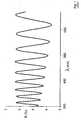
Figure 1 is an illustration of a reflection spectrum in the visible range of a substrate having a coating layer whereby the substrate and the coating layer have a different refractive index;Figure 2 is an illustration of a reflection spectrum in the visible range of a substrate coated with a low iridescent coating according to the present invention;Figure 3 is an illustration of a reflection spectrum in the visible range of glass substrate provided with a window film.- The present invention will be further described with respect to particular embodiments and with reference to certain drawings.
- The term first, second and the like in the description and the claims are used for distinguishing between similar elements and not necessarily for describing a sequence, either temporally, spatially, in ranking or in any other manner.
- A first example of a coated substrate comprises a PET film coated with a hard coating. The hard coating comprises an acrylate based coating, more particularly a 95 wt% mixture of penta erythritol acrylates multifunctional monomers, 2 wt% additives and 3 wt% of UV cure initiators. The coating has a thickness ranging between 1.5 and 3 µm. The hard coating has a refractive index at 510 of 1.48. The PET film has a thickness of 23 µm and a refractive index at 510 nm of 1.65.
- The reflection spectrum of this coated substrate is given in
Figure 1 . The reflection pattern ofFigure 1 shows pronounced fringes in the visible range. - A second example comprises a substrate coated with hard coating layer according to the present invention. The hard coating comprises an acrylate based coating as mentioned in the first example having a thickness ranging between 1.5 and 3 µm. The substrate comprises a PET film having a thickness of 23 µm and having a refractive index at 510 nm of 1.65. The hard coating further comprise ZrO2 nanoparticles. The concentration of ZrO2 nanoparticles is chosen in order to match the difference in refractive index between the substrate and the hard coating.
- The reflection spectrum of this coated substrate is given in
Figure 2 . Compared toFigure 2 , the fringes in the visible range are less pronounced resulting in a coated substrate showing no iridescence. - A third example comprises a glass substrate provided with a window film. The window film comprises a PET substrate and a hard coating comprising ZrO2 particles. The window film is laminated to the glass substrate by means of an adhesive. The PET substrate has a thickness of 23 µm and the glass substrate is 3 mm clear glass. The hard coating comprises an acrylate based coating as mentioned in the first example.
- Three different embodiments of window films are considered each having a different concentration of ZrO2 particles :
- a first embodiment A comprises a hard coating without added ZrO2 particles;
- a second embodiment B comprises a hard coating having a low volume fraction of ZrO2 particles;
- a third embodiment C comprises a hard coating having a volume fraction of ZrO2 particles to match the difference in refractive index between the PET substrate and the hard coating.
- The reflection spectra of the glass provided with different embodiments of window films are given in
Figure 3 .
FromFigure 3 it can be concluded that the fringes of the spectra are reduced by increasing the concentration of nanoparticles in the hard coating so that the difference in refractive index between the PET substrate and the hard coating is reduced.


Claims (15)
- A layered structure comprising at least a first layer having a refractive index η1 and a second layer having a refractive index η2, said first layer comprising a first matrix material having a refractive index ηmatrix and said second layer comprising a second matrix material having a refractive index ηmatrix 2, the difference between said refractive index of said first matrix material ηmatrix 1 and said refractive index of said second matrix material ηmatrix 2 at a wavelength of 510 nm being at least 0.1;characterised in that at least one of said first layer or said second layer comprises nanoparticles having a diameter ranging between 1 and 500 nm in a volume fraction to match the difference in refractive index between the first matrix material ηmatrix and the second matrix material ηmatrix 2 in such a way that the difference between the refractive index of the first layer η1 and the refractive index of the second layer η2 at each wavelength of the visible range from 380 to 750 nm is less than 0.08.
- A layered structure according to claim 1, whereby said first layer and said second layer comprise nanoparticles.
- A layered structure according to claim 1 or 2, whereby said nanoparticles comprise organic or inorganic nanoparticles or a combination of organic and inorganic nanoparticles.
- A layered structure according to any one of the preceding claims, whereby said nanoparticles are selected from the group consisting of oxides particles, sulphide particles, nitride particles, doped oxide particles, doped sulphide particles, doped nitride particles and combinations thereof.
- A layered structure according to claim 4, whereby said nanoparticles are selected from the group consisting of aluminum oxide, silicon oxide, zirconium oxide, titanium oxide, antimony oxide, zinc oxide, tin oxide, indium oxide, indium tin oxide, cerium oxide, niobium oxide, vanadium oxide, tungsten oxide, tantalium oxide, zinc sulphide, silicon nitride, doped variants thereof and mixtures thereof.
- A layered structure according to any one of the preceding claims, whereby said nanoparticles comprises organic groups on their surface, said organic groups forming a crosslinked network with said matrix material.
- A layered structure according to claim 6, whereby said organic groups comprises acrylate groups and/or methacrylate groups.
- A window film comprising a layered structure comprising at least a first layer and a second layer as defined in any one of claims 1 to 7.
- A window film according to claim 8, whereby at least one of said first layer and said second layer comprises a glass substrate or a polymer substrate.
- A window film according to any one of claims 8 or 9, whereby at least one of said first and said second layer comprises a coating layer.
- A window film according to any one of claims 8 to 10, whereby said first layer comprises a polymer substrate or a glass substrate and whereby said second layer comprises a coating layer applied on said first layer, said second layer comprising nanoparticles.
- A window film according to any one of claims 8 to 11, whereby said coating layer is functioning as a hard coating, an adhesive, an infrared absorbing layer or an anti-fog layer.
- A method to match the difference in refractive index between a first layer having a refractive index n1 and a second layer having a refractive index η2; said first layer comprising a first matrix material having a refractive index ηmatrix1 and said second layer comprising a second matrix material having a refractive index ηmatrix2, the difference between said refractive index ηmatrix1 and said refractive index ηmatrix2 at a wavelength of 510 nm being at least 0.1, said method comprises the step of incorporating nanoparticles having a diameter ranging between 1 and 500 nm in at least one of said first or said second matrix material, whereby said nanoparticles are present in a volume fraction that the difference in refractive index at each wavelength of the visible range from 380 nm to 750 nm is less than 0.08.
- A method according to claim 13, whereby said first layer and said second layer comprise nanoparticles.
- A method according to any one of claims 13 or 14, whereby said nanoparticles are selected from the group consisting of oxides particles, sulphide particles, nitride particles, doped oxide particles, doped sulphide particles, doped nitride particles and combinations thereof.
Priority Applications (1)
| Application Number | Priority Date | Filing Date | Title |
|---|---|---|---|
| EP08717020.5AEP2125941B1 (en) | 2007-02-26 | 2008-02-21 | A layered structure comprising nanoparticles |
Applications Claiming Priority (3)
| Application Number | Priority Date | Filing Date | Title |
|---|---|---|---|
| EP07103056 | 2007-02-26 | ||
| EP08717020.5AEP2125941B1 (en) | 2007-02-26 | 2008-02-21 | A layered structure comprising nanoparticles |
| PCT/EP2008/052152WO2008104502A1 (en) | 2007-02-26 | 2008-02-21 | A layered structure comprising nanoparticles |
Publications (2)
| Publication Number | Publication Date |
|---|---|
| EP2125941A1 EP2125941A1 (en) | 2009-12-02 |
| EP2125941B1true EP2125941B1 (en) | 2013-05-01 |
Family
ID=38261520
Family Applications (1)
| Application Number | Title | Priority Date | Filing Date |
|---|---|---|---|
| EP08717020.5ANot-in-forceEP2125941B1 (en) | 2007-02-26 | 2008-02-21 | A layered structure comprising nanoparticles |
Country Status (6)
| Country | Link |
|---|---|
| US (1) | US20090305013A1 (en) |
| EP (1) | EP2125941B1 (en) |
| JP (1) | JP5453113B2 (en) |
| CN (1) | CN101611080B (en) |
| ES (1) | ES2424189T3 (en) |
| WO (1) | WO2008104502A1 (en) |
Families Citing this family (7)
| Publication number | Priority date | Publication date | Assignee | Title |
|---|---|---|---|---|
| CN102127326B (en)* | 2010-12-28 | 2012-10-31 | 中国科学院上海硅酸盐研究所 | A kind of vanadium dioxide-based composite coating liquid and composite thin film and its preparation method and application |
| JP6467610B2 (en)* | 2012-06-26 | 2019-02-13 | 株式会社ニコン | Liquid polymerizable composition comprising mineral nanoparticles and use thereof for making optical articles |
| CN103640299B (en)* | 2013-11-26 | 2016-05-18 | 上海紫东薄膜材料股份有限公司 | A kind of co-extruding biaxial stretched functional polyester intelligent light modulation film and preparation method thereof |
| CN103640302B (en)* | 2013-11-26 | 2016-05-18 | 上海紫东薄膜材料股份有限公司 | A kind of 3 layer co-extruding biaxial stretched functional polyester membrane structures |
| TWI624521B (en)* | 2013-12-23 | 2018-05-21 | 聖高拜塑膠製品公司 | Coating materials and low haze heat rejection composites |
| CN108137957B (en)* | 2016-03-30 | 2021-07-27 | Ppg涂料(天津)有限公司 | Light Diffusing and Reflective Coatings |
| CN107384231A (en)* | 2017-06-07 | 2017-11-24 | 常州诺澜复合材料有限公司 | A kind of preparation method of nano ceramics heat insulating membrane |
Family Cites Families (24)
| Publication number | Priority date | Publication date | Assignee | Title |
|---|---|---|---|---|
| JP4001619B2 (en)* | 1992-10-29 | 2007-10-31 | スリーエム カンパニー | Moldable reflective multilayer object |
| US6498683B2 (en)* | 1999-11-22 | 2002-12-24 | 3M Innovative Properties Company | Multilayer optical bodies |
| TW415888B (en)* | 1998-02-17 | 2000-12-21 | Nippon Kayaku Kk | Transparent sheet or film |
| US6379774B1 (en)* | 1998-05-21 | 2002-04-30 | Teijin Limited | Composite polyester film and magnetic recording medium |
| DE19823732A1 (en)* | 1998-05-27 | 1999-12-02 | Inst Neue Mat Gemein Gmbh | Process for the production of optical multilayer systems |
| US6329058B1 (en)* | 1998-07-30 | 2001-12-11 | 3M Innovative Properties Company | Nanosize metal oxide particles for producing transparent metal oxide colloids and ceramers |
| US5956175A (en)* | 1998-07-31 | 1999-09-21 | Msc Specialty Films Inc | Solar control window film |
| JP4609962B2 (en)* | 2000-02-02 | 2011-01-12 | 日東電工株式会社 | Optical film |
| AU4884801A (en)* | 2000-05-18 | 2001-11-26 | Bridgestone Corporation | Display panel, and electromagnetic shielding light transmitting window material manufacturing method |
| TW574110B (en)* | 2001-10-25 | 2004-02-01 | Matsushita Electric Works Ltd | Composite thin film holding substrate, transparent conductive film holding substrate, and panel light emitting body |
| WO2003049943A1 (en)* | 2001-12-10 | 2003-06-19 | Teijin Dupont Films Japan Limited | Adhesive polyester film for optical use |
| US20030175004A1 (en)* | 2002-02-19 | 2003-09-18 | Garito Anthony F. | Optical polymer nanocomposites |
| CN1204170C (en)* | 2002-08-08 | 2005-06-01 | 吉林大学 | Preparation method of nano particles with high refractive index and polymer nano composite film material |
| US7094461B2 (en)* | 2002-12-31 | 2006-08-22 | 3M Innovative Properties Company | P-polarizer with large z-axis refractive index difference |
| DE602004010501T2 (en)* | 2003-03-25 | 2008-11-13 | Teijin Dupont Films Japan Ltd. | ANTISTATIC COATED POLYESTER FOIL |
| JP2005096298A (en)* | 2003-09-25 | 2005-04-14 | Dainippon Printing Co Ltd | Optical film and optical display device comprising this optical film |
| US6842288B1 (en)* | 2003-10-30 | 2005-01-11 | 3M Innovative Properties Company | Multilayer optical adhesives and articles |
| JP2005215283A (en)* | 2004-01-29 | 2005-08-11 | Toppan Printing Co Ltd | Antistatic hard coat film and display medium |
| US7119140B2 (en)* | 2004-07-22 | 2006-10-10 | Ronald Basham | Transparent films, compositions, and method of manufacture thereof |
| US20070004813A1 (en)* | 2004-09-16 | 2007-01-04 | Eastman Chemical Company | Compositions for the preparation of void-containing articles |
| US7491441B2 (en)* | 2004-12-30 | 2009-02-17 | 3M Innovative Properties Company | High refractive index, durable hard coats |
| JP4673664B2 (en)* | 2005-04-27 | 2011-04-20 | 三井化学株式会社 | High refractive index resin composition for coating |
| US20060255486A1 (en)* | 2005-05-10 | 2006-11-16 | Benson Olester Jr | Method of manufacturing composite optical body containing inorganic fibers |
| US20070292679A1 (en)* | 2006-06-14 | 2007-12-20 | 3M Innovative Properties Company | Optical article having an antistatic fluorochemical surface layer |
- 2008
- 2008-02-21EPEP08717020.5Apatent/EP2125941B1/ennot_activeNot-in-force
- 2008-02-21CNCN2008800050412Apatent/CN101611080B/ennot_activeExpired - Fee Related
- 2008-02-21ESES08717020Tpatent/ES2424189T3/enactiveActive
- 2008-02-21USUS12/523,376patent/US20090305013A1/ennot_activeAbandoned
- 2008-02-21JPJP2009550717Apatent/JP5453113B2/ennot_activeExpired - Fee Related
- 2008-02-21WOPCT/EP2008/052152patent/WO2008104502A1/enactiveApplication Filing
Also Published As
| Publication number | Publication date |
|---|---|
| EP2125941A1 (en) | 2009-12-02 |
| US20090305013A1 (en) | 2009-12-10 |
| CN101611080A (en) | 2009-12-23 |
| JP5453113B2 (en) | 2014-03-26 |
| CN101611080B (en) | 2011-12-28 |
| ES2424189T3 (en) | 2013-09-27 |
| JP2010519084A (en) | 2010-06-03 |
| WO2008104502A1 (en) | 2008-09-04 |
Similar Documents
| Publication | Publication Date | Title |
|---|---|---|
| JP6553897B2 (en) | Transparent thermal insulation member and method of manufacturing the same | |
| EP2125941B1 (en) | A layered structure comprising nanoparticles | |
| KR101452598B1 (en) | Optical laminate, polarizing plate and image display device | |
| JP6070195B2 (en) | Antireflection film, method for producing antireflection film, polarizing plate and image display device | |
| US9778402B2 (en) | Light reflective film and light reflector produced using the same | |
| KR101555411B1 (en) | Transparent conductive film and use thereof | |
| US9971077B2 (en) | Multilayer structure and laminate structure | |
| US6191884B1 (en) | Infrared-blocking transparent film | |
| JP6730871B2 (en) | Optical body, window material and roll curtain | |
| JPWO2013111735A1 (en) | Optical film | |
| WO2019065009A1 (en) | Optical body and window material | |
| JPWO2014199872A1 (en) | Infrared shielding film, infrared shielding body using the same and heat ray reflective laminated glass | |
| JP3901911B2 (en) | Transparent laminated film | |
| JP2014145914A (en) | Antireflection film and manufacturing method thereof | |
| JP6428608B2 (en) | Infrared shielding film, infrared shielding film installation method and infrared shielding film iris prevention method | |
| TW201736868A (en) | Optical body and glass material | |
| JP2015150851A (en) | Method for producing functional film | |
| JP2010181801A (en) | Coating composition, antireflection film using the same, and method for forming antireflection film | |
| JP6326780B2 (en) | Window pasting film | |
| JP2010014819A (en) | Anti-reflection film | |
| JP2016118632A (en) | Method for manufacturing optical control film | |
| JPWO2015037514A1 (en) | Method for producing dielectric multilayer film | |
| WO2017175588A1 (en) | Optical body, window material, and roll curtain | |
| JP6783348B2 (en) | Transparent heat shield and heat insulating member and its manufacturing method | |
| JP2017191304A (en) | Optical body, window material, and roll curtain |
Legal Events
| Date | Code | Title | Description |
|---|---|---|---|
| PUAI | Public reference made under article 153(3) epc to a published international application that has entered the european phase | Free format text:ORIGINAL CODE: 0009012 | |
| 17P | Request for examination filed | Effective date:20090709 | |
| AK | Designated contracting states | Kind code of ref document:A1 Designated state(s):AT BE BG CH CY CZ DE DK EE ES FI FR GB GR HR HU IE IS IT LI LT LU LV MC MT NL NO PL PT RO SE SI SK TR | |
| DAX | Request for extension of the european patent (deleted) | ||
| GRAP | Despatch of communication of intention to grant a patent | Free format text:ORIGINAL CODE: EPIDOSNIGR1 | |
| RAP1 | Party data changed (applicant data changed or rights of an application transferred) | Owner name:SAINT-GOBAIN PERFORMANCE PLASTICS CHAINEUX S.A. | |
| GRAS | Grant fee paid | Free format text:ORIGINAL CODE: EPIDOSNIGR3 | |
| GRAP | Despatch of communication of intention to grant a patent | Free format text:ORIGINAL CODE: EPIDOSNIGR1 | |
| GRAA | (expected) grant | Free format text:ORIGINAL CODE: 0009210 | |
| AK | Designated contracting states | Kind code of ref document:B1 Designated state(s):AT BE BG CH CY CZ DE DK EE ES FI FR GB GR HR HU IE IS IT LI LT LU LV MC MT NL NO PL PT RO SE SI SK TR | |
| REG | Reference to a national code | Ref country code:GB Ref legal event code:FG4D | |
| REG | Reference to a national code | Ref country code:CH Ref legal event code:EP Ref country code:AT Ref legal event code:REF Ref document number:609932 Country of ref document:AT Kind code of ref document:T Effective date:20130515 | |
| REG | Reference to a national code | Ref country code:IE Ref legal event code:FG4D | |
| REG | Reference to a national code | Ref country code:DE Ref legal event code:R096 Ref document number:602008024263 Country of ref document:DE Effective date:20130627 | |
| REG | Reference to a national code | Ref country code:AT Ref legal event code:MK05 Ref document number:609932 Country of ref document:AT Kind code of ref document:T Effective date:20130501 | |
| REG | Reference to a national code | Ref country code:ES Ref legal event code:FG2A Ref document number:2424189 Country of ref document:ES Kind code of ref document:T3 Effective date:20130927 | |
| REG | Reference to a national code | Ref country code:NL Ref legal event code:VDEP Effective date:20130501 | |
| REG | Reference to a national code | Ref country code:LT Ref legal event code:MG4D | |
| PG25 | Lapsed in a contracting state [announced via postgrant information from national office to epo] | Ref country code:PT Free format text:LAPSE BECAUSE OF FAILURE TO SUBMIT A TRANSLATION OF THE DESCRIPTION OR TO PAY THE FEE WITHIN THE PRESCRIBED TIME-LIMIT Effective date:20130902 Ref country code:FI Free format text:LAPSE BECAUSE OF FAILURE TO SUBMIT A TRANSLATION OF THE DESCRIPTION OR TO PAY THE FEE WITHIN THE PRESCRIBED TIME-LIMIT Effective date:20130501 Ref country code:AT Free format text:LAPSE BECAUSE OF FAILURE TO SUBMIT A TRANSLATION OF THE DESCRIPTION OR TO PAY THE FEE WITHIN THE PRESCRIBED TIME-LIMIT Effective date:20130501 Ref country code:GR Free format text:LAPSE BECAUSE OF FAILURE TO SUBMIT A TRANSLATION OF THE DESCRIPTION OR TO PAY THE FEE WITHIN THE PRESCRIBED TIME-LIMIT Effective date:20130802 Ref country code:IS Free format text:LAPSE BECAUSE OF FAILURE TO SUBMIT A TRANSLATION OF THE DESCRIPTION OR TO PAY THE FEE WITHIN THE PRESCRIBED TIME-LIMIT Effective date:20130901 Ref country code:SI Free format text:LAPSE BECAUSE OF FAILURE TO SUBMIT A TRANSLATION OF THE DESCRIPTION OR TO PAY THE FEE WITHIN THE PRESCRIBED TIME-LIMIT Effective date:20130501 Ref country code:SE Free format text:LAPSE BECAUSE OF FAILURE TO SUBMIT A TRANSLATION OF THE DESCRIPTION OR TO PAY THE FEE WITHIN THE PRESCRIBED TIME-LIMIT Effective date:20130501 Ref country code:LT Free format text:LAPSE BECAUSE OF FAILURE TO SUBMIT A TRANSLATION OF THE DESCRIPTION OR TO PAY THE FEE WITHIN THE PRESCRIBED TIME-LIMIT Effective date:20130501 Ref country code:NO Free format text:LAPSE BECAUSE OF FAILURE TO SUBMIT A TRANSLATION OF THE DESCRIPTION OR TO PAY THE FEE WITHIN THE PRESCRIBED TIME-LIMIT Effective date:20130801 | |
| PG25 | Lapsed in a contracting state [announced via postgrant information from national office to epo] | Ref country code:HR Free format text:LAPSE BECAUSE OF FAILURE TO SUBMIT A TRANSLATION OF THE DESCRIPTION OR TO PAY THE FEE WITHIN THE PRESCRIBED TIME-LIMIT Effective date:20130501 Ref country code:PL Free format text:LAPSE BECAUSE OF FAILURE TO SUBMIT A TRANSLATION OF THE DESCRIPTION OR TO PAY THE FEE WITHIN THE PRESCRIBED TIME-LIMIT Effective date:20130501 Ref country code:BG Free format text:LAPSE BECAUSE OF FAILURE TO SUBMIT A TRANSLATION OF THE DESCRIPTION OR TO PAY THE FEE WITHIN THE PRESCRIBED TIME-LIMIT Effective date:20130801 Ref country code:CY Free format text:LAPSE BECAUSE OF FAILURE TO SUBMIT A TRANSLATION OF THE DESCRIPTION OR TO PAY THE FEE WITHIN THE PRESCRIBED TIME-LIMIT Effective date:20130501 | |
| PG25 | Lapsed in a contracting state [announced via postgrant information from national office to epo] | Ref country code:LV Free format text:LAPSE BECAUSE OF FAILURE TO SUBMIT A TRANSLATION OF THE DESCRIPTION OR TO PAY THE FEE WITHIN THE PRESCRIBED TIME-LIMIT Effective date:20130501 | |
| PG25 | Lapsed in a contracting state [announced via postgrant information from national office to epo] | Ref country code:EE Free format text:LAPSE BECAUSE OF FAILURE TO SUBMIT A TRANSLATION OF THE DESCRIPTION OR TO PAY THE FEE WITHIN THE PRESCRIBED TIME-LIMIT Effective date:20130501 Ref country code:CZ Free format text:LAPSE BECAUSE OF FAILURE TO SUBMIT A TRANSLATION OF THE DESCRIPTION OR TO PAY THE FEE WITHIN THE PRESCRIBED TIME-LIMIT Effective date:20130501 Ref country code:SK Free format text:LAPSE BECAUSE OF FAILURE TO SUBMIT A TRANSLATION OF THE DESCRIPTION OR TO PAY THE FEE WITHIN THE PRESCRIBED TIME-LIMIT Effective date:20130501 Ref country code:BE Free format text:LAPSE BECAUSE OF FAILURE TO SUBMIT A TRANSLATION OF THE DESCRIPTION OR TO PAY THE FEE WITHIN THE PRESCRIBED TIME-LIMIT Effective date:20130501 Ref country code:DK Free format text:LAPSE BECAUSE OF FAILURE TO SUBMIT A TRANSLATION OF THE DESCRIPTION OR TO PAY THE FEE WITHIN THE PRESCRIBED TIME-LIMIT Effective date:20130501 | |
| PG25 | Lapsed in a contracting state [announced via postgrant information from national office to epo] | Ref country code:RO Free format text:LAPSE BECAUSE OF FAILURE TO SUBMIT A TRANSLATION OF THE DESCRIPTION OR TO PAY THE FEE WITHIN THE PRESCRIBED TIME-LIMIT Effective date:20130501 Ref country code:NL Free format text:LAPSE BECAUSE OF FAILURE TO SUBMIT A TRANSLATION OF THE DESCRIPTION OR TO PAY THE FEE WITHIN THE PRESCRIBED TIME-LIMIT Effective date:20130501 Ref country code:IT Free format text:LAPSE BECAUSE OF FAILURE TO SUBMIT A TRANSLATION OF THE DESCRIPTION OR TO PAY THE FEE WITHIN THE PRESCRIBED TIME-LIMIT Effective date:20130501 | |
| PLBE | No opposition filed within time limit | Free format text:ORIGINAL CODE: 0009261 | |
| STAA | Information on the status of an ep patent application or granted ep patent | Free format text:STATUS: NO OPPOSITION FILED WITHIN TIME LIMIT | |
| 26N | No opposition filed | Effective date:20140204 | |
| REG | Reference to a national code | Ref country code:DE Ref legal event code:R097 Ref document number:602008024263 Country of ref document:DE Effective date:20140204 | |
| PG25 | Lapsed in a contracting state [announced via postgrant information from national office to epo] | Ref country code:MC Free format text:LAPSE BECAUSE OF FAILURE TO SUBMIT A TRANSLATION OF THE DESCRIPTION OR TO PAY THE FEE WITHIN THE PRESCRIBED TIME-LIMIT Effective date:20130501 Ref country code:LU Free format text:LAPSE BECAUSE OF FAILURE TO SUBMIT A TRANSLATION OF THE DESCRIPTION OR TO PAY THE FEE WITHIN THE PRESCRIBED TIME-LIMIT Effective date:20140221 | |
| REG | Reference to a national code | Ref country code:CH Ref legal event code:PL | |
| PG25 | Lapsed in a contracting state [announced via postgrant information from national office to epo] | Ref country code:LI Free format text:LAPSE BECAUSE OF NON-PAYMENT OF DUE FEES Effective date:20140228 Ref country code:CH Free format text:LAPSE BECAUSE OF NON-PAYMENT OF DUE FEES Effective date:20140228 | |
| REG | Reference to a national code | Ref country code:IE Ref legal event code:MM4A | |
| PG25 | Lapsed in a contracting state [announced via postgrant information from national office to epo] | Ref country code:IE Free format text:LAPSE BECAUSE OF NON-PAYMENT OF DUE FEES Effective date:20140221 | |
| REG | Reference to a national code | Ref country code:FR Ref legal event code:PLFP Year of fee payment:9 | |
| PG25 | Lapsed in a contracting state [announced via postgrant information from national office to epo] | Ref country code:MT Free format text:LAPSE BECAUSE OF FAILURE TO SUBMIT A TRANSLATION OF THE DESCRIPTION OR TO PAY THE FEE WITHIN THE PRESCRIBED TIME-LIMIT Effective date:20130501 | |
| PG25 | Lapsed in a contracting state [announced via postgrant information from national office to epo] | Ref country code:TR Free format text:LAPSE BECAUSE OF FAILURE TO SUBMIT A TRANSLATION OF THE DESCRIPTION OR TO PAY THE FEE WITHIN THE PRESCRIBED TIME-LIMIT Effective date:20130501 Ref country code:HU Free format text:LAPSE BECAUSE OF FAILURE TO SUBMIT A TRANSLATION OF THE DESCRIPTION OR TO PAY THE FEE WITHIN THE PRESCRIBED TIME-LIMIT; INVALID AB INITIO Effective date:20080221 | |
| REG | Reference to a national code | Ref country code:FR Ref legal event code:PLFP Year of fee payment:10 | |
| REG | Reference to a national code | Ref country code:FR Ref legal event code:PLFP Year of fee payment:11 | |
| PGFP | Annual fee paid to national office [announced via postgrant information from national office to epo] | Ref country code:FR Payment date:20190123 Year of fee payment:12 Ref country code:DE Payment date:20190122 Year of fee payment:12 Ref country code:GB Payment date:20190125 Year of fee payment:12 Ref country code:ES Payment date:20190301 Year of fee payment:12 | |
| REG | Reference to a national code | Ref country code:DE Ref legal event code:R119 Ref document number:602008024263 Country of ref document:DE | |
| GBPC | Gb: european patent ceased through non-payment of renewal fee | Effective date:20200221 | |
| PG25 | Lapsed in a contracting state [announced via postgrant information from national office to epo] | Ref country code:FR Free format text:LAPSE BECAUSE OF NON-PAYMENT OF DUE FEES Effective date:20200229 Ref country code:DE Free format text:LAPSE BECAUSE OF NON-PAYMENT OF DUE FEES Effective date:20200901 Ref country code:GB Free format text:LAPSE BECAUSE OF NON-PAYMENT OF DUE FEES Effective date:20200221 | |
| REG | Reference to a national code | Ref country code:ES Ref legal event code:FD2A Effective date:20210708 | |
| PG25 | Lapsed in a contracting state [announced via postgrant information from national office to epo] | Ref country code:ES Free format text:LAPSE BECAUSE OF NON-PAYMENT OF DUE FEES Effective date:20200222 |