EP2124847B1 - Endoluminal prosthesis - Google Patents
Endoluminal prosthesisDownload PDFInfo
- Publication number
- EP2124847B1 EP2124847B1EP07736720AEP07736720AEP2124847B1EP 2124847 B1EP2124847 B1EP 2124847B1EP 07736720 AEP07736720 AEP 07736720AEP 07736720 AEP07736720 AEP 07736720AEP 2124847 B1EP2124847 B1EP 2124847B1
- Authority
- EP
- European Patent Office
- Prior art keywords
- stent
- thread
- bands
- poly
- serpentine
- Prior art date
- Legal status (The legal status is an assumption and is not a legal conclusion. Google has not performed a legal analysis and makes no representation as to the accuracy of the status listed.)
- Ceased
Links
- WYTGDNHDOZPMIW-RCBQFDQVSA-NalstonineNatural productsC1=CC2=C3C=CC=CC3=NC2=C2N1C[C@H]1[C@H](C)OC=C(C(=O)OC)[C@H]1C2WYTGDNHDOZPMIW-RCBQFDQVSA-N0.000claimsdescription76
- 239000000463materialSubstances0.000claimsdescription43
- 229920000642polymerPolymers0.000claimsdescription17
- 239000000203mixtureSubstances0.000claimsdescription13
- 239000003623enhancerSubstances0.000claimsdescription10
- 229910000861Mg alloyInorganic materials0.000claimsdescription9
- 239000010935stainless steelSubstances0.000claimsdescription8
- 229910001220stainless steelInorganic materials0.000claimsdescription8
- HLXZNVUGXRDIFK-UHFFFAOYSA-Nnickel titaniumChemical compound[Ti].[Ti].[Ti].[Ti].[Ti].[Ti].[Ti].[Ti].[Ti].[Ti].[Ti].[Ni].[Ni].[Ni].[Ni].[Ni].[Ni].[Ni].[Ni].[Ni].[Ni].[Ni].[Ni].[Ni].[Ni]HLXZNVUGXRDIFK-UHFFFAOYSA-N0.000claimsdescription7
- 229910001000nickel titaniumInorganic materials0.000claimsdescription7
- 238000004026adhesive bondingMethods0.000claimsdescription6
- -1polytetrafluoroethylenePolymers0.000claimsdescription6
- 239000004952PolyamideSubstances0.000claimsdescription4
- 229920000954PolyglycolidePolymers0.000claimsdescription4
- ZQBZAOZWBKABNC-UHFFFAOYSA-N[P].[Ca]Chemical compound[P].[Ca]ZQBZAOZWBKABNC-UHFFFAOYSA-N0.000claimsdescription4
- 239000003814drugSubstances0.000claimsdescription4
- 229940079593drugDrugs0.000claimsdescription4
- 239000003550markerSubstances0.000claimsdescription4
- 229920001432poly(L-lactide)Polymers0.000claimsdescription4
- 229920002647polyamidePolymers0.000claimsdescription4
- 229920001343polytetrafluoroethylenePolymers0.000claimsdescription4
- 239000004810polytetrafluoroethyleneSubstances0.000claimsdescription4
- 238000004804windingMethods0.000claimsdescription4
- 229910000531Co alloyInorganic materials0.000claimsdescription3
- IUWCPXJTIPQGTE-UHFFFAOYSA-Nchromium cobaltChemical compound[Cr].[Co].[Co].[Co]IUWCPXJTIPQGTE-UHFFFAOYSA-N0.000claimsdescription3
- 230000007423decreaseEffects0.000claimsdescription3
- 239000007769metal materialSubstances0.000claimsdescription3
- 230000002035prolonged effectEffects0.000claimsdescription3
- KIUKXJAPPMFGSW-DNGZLQJQSA-N(2S,3S,4S,5R,6R)-6-[(2S,3R,4R,5S,6R)-3-Acetamido-2-[(2S,3S,4R,5R,6R)-6-[(2R,3R,4R,5S,6R)-3-acetamido-2,5-dihydroxy-6-(hydroxymethyl)oxan-4-yl]oxy-2-carboxy-4,5-dihydroxyoxan-3-yl]oxy-5-hydroxy-6-(hydroxymethyl)oxan-4-yl]oxy-3,4,5-trihydroxyoxane-2-carboxylic acidChemical compoundCC(=O)N[C@H]1[C@H](O)O[C@H](CO)[C@@H](O)[C@@H]1O[C@H]1[C@H](O)[C@@H](O)[C@H](O[C@H]2[C@@H]([C@@H](O[C@H]3[C@@H]([C@@H](O)[C@H](O)[C@H](O3)C(O)=O)O)[C@H](O)[C@@H](CO)O2)NC(C)=O)[C@@H](C(O)=O)O1KIUKXJAPPMFGSW-DNGZLQJQSA-N0.000claimsdescription2
- RBMHUYBJIYNRLY-UHFFFAOYSA-N2-[(1-carboxy-1-hydroxyethyl)-hydroxyphosphoryl]-2-hydroxypropanoic acidChemical compoundOC(=O)C(O)(C)P(O)(=O)C(C)(O)C(O)=ORBMHUYBJIYNRLY-UHFFFAOYSA-N0.000claimsdescription2
- BVKZGUZCCUSVTD-UHFFFAOYSA-LCarbonateChemical compound[O-]C([O-])=OBVKZGUZCCUSVTD-UHFFFAOYSA-L0.000claimsdescription2
- 102000008186CollagenHuman genes0.000claimsdescription2
- 108010035532CollagenProteins0.000claimsdescription2
- 229920001651CyanoacrylatePolymers0.000claimsdescription2
- JOYRKODLDBILNP-UHFFFAOYSA-NEthyl urethaneChemical compoundCCOC(N)=OJOYRKODLDBILNP-UHFFFAOYSA-N0.000claimsdescription2
- IAYPIBMASNFSPL-UHFFFAOYSA-NEthylene oxideChemical compoundC1CO1IAYPIBMASNFSPL-UHFFFAOYSA-N0.000claimsdescription2
- 102000009123FibrinHuman genes0.000claimsdescription2
- 108010073385FibrinProteins0.000claimsdescription2
- BWGVNKXGVNDBDI-UHFFFAOYSA-NFibrin monomerChemical compoundCNC(=O)CNC(=O)CNBWGVNKXGVNDBDI-UHFFFAOYSA-N0.000claimsdescription2
- 102000008946FibrinogenHuman genes0.000claimsdescription2
- 108010049003FibrinogenProteins0.000claimsdescription2
- JVTAAEKCZFNVCJ-REOHCLBHSA-NL-lactic acidChemical compoundC[C@H](O)C(O)=OJVTAAEKCZFNVCJ-REOHCLBHSA-N0.000claimsdescription2
- 229920002472StarchPolymers0.000claimsdescription2
- 150000008064anhydridesChemical class0.000claimsdescription2
- 229920002678cellulosePolymers0.000claimsdescription2
- 239000001913celluloseSubstances0.000claimsdescription2
- 229920001436collagenPolymers0.000claimsdescription2
- NLCKLZIHJQEMCU-UHFFFAOYSA-Ncyano prop-2-enoateChemical classC=CC(=O)OC#NNLCKLZIHJQEMCU-UHFFFAOYSA-N0.000claimsdescription2
- 229940117927ethylene oxideDrugs0.000claimsdescription2
- 239000005038ethylene vinyl acetateSubstances0.000claimsdescription2
- 229950003499fibrinDrugs0.000claimsdescription2
- 229940012952fibrinogenDrugs0.000claimsdescription2
- 229920002674hyaluronanPolymers0.000claimsdescription2
- 229960003160hyaluronic acidDrugs0.000claimsdescription2
- 229920000118poly(D-lactic acid)Polymers0.000claimsdescription2
- 229920001434poly(D-lactide)Polymers0.000claimsdescription2
- 229920001308poly(aminoacid)Polymers0.000claimsdescription2
- 229920001200poly(ethylene-vinyl acetate)Polymers0.000claimsdescription2
- 229920006211poly(glycolic acid-co-trimethylene carbonate)Polymers0.000claimsdescription2
- 229920001849poly(hydroxybutyrate-co-valerate)Polymers0.000claimsdescription2
- 229920000747poly(lactic acid)Polymers0.000claimsdescription2
- 229920001606poly(lactic acid-co-glycolic acid)Polymers0.000claimsdescription2
- 239000002745poly(ortho ester)Substances0.000claimsdescription2
- 239000004632polycaprolactoneSubstances0.000claimsdescription2
- 239000000622polydioxanoneSubstances0.000claimsdescription2
- 229920000166polytrimethylene carbonatePolymers0.000claimsdescription2
- OHRURASPPZQGQM-GCCNXGTGSA-NromidepsinChemical compoundO1C(=O)[C@H](C(C)C)NC(=O)C(=C/C)/NC(=O)[C@H]2CSSCC\C=C\[C@@H]1CC(=O)N[C@H](C(C)C)C(=O)N2OHRURASPPZQGQM-GCCNXGTGSA-N0.000claimsdescription2
- 239000007787solidSubstances0.000claimsdescription2
- 239000008107starchSubstances0.000claimsdescription2
- 235000019698starchNutrition0.000claimsdescription2
- 229910045601alloyInorganic materials0.000description16
- 239000000956alloySubstances0.000description16
- 239000007943implantSubstances0.000description10
- PXHVJJICTQNCMI-UHFFFAOYSA-NNickelChemical compound[Ni]PXHVJJICTQNCMI-UHFFFAOYSA-N0.000description8
- XEEYBQQBJWHFJM-UHFFFAOYSA-NIronChemical compound[Fe]XEEYBQQBJWHFJM-UHFFFAOYSA-N0.000description6
- 238000005516engineering processMethods0.000description6
- DLYUQMMRRRQYAE-UHFFFAOYSA-Ntetraphosphorus decaoxideChemical compoundO1P(O2)(=O)OP3(=O)OP1(=O)OP2(=O)O3DLYUQMMRRRQYAE-UHFFFAOYSA-N0.000description6
- FYYHWMGAXLPEAU-UHFFFAOYSA-NMagnesiumChemical compound[Mg]FYYHWMGAXLPEAU-UHFFFAOYSA-N0.000description5
- 239000011777magnesiumSubstances0.000description5
- 229910052749magnesiumInorganic materials0.000description5
- 229910052751metalInorganic materials0.000description5
- 239000002184metalSubstances0.000description5
- 230000001154acute effectEffects0.000description4
- 230000006399behaviorEffects0.000description4
- 230000008878couplingEffects0.000description4
- 238000010168coupling processMethods0.000description4
- 238000005859coupling reactionMethods0.000description4
- 229910052759nickelInorganic materials0.000description4
- ODINCKMPIJJUCX-UHFFFAOYSA-NCalcium oxideChemical compound[Ca]=OODINCKMPIJJUCX-UHFFFAOYSA-N0.000description3
- 238000005520cutting processMethods0.000description3
- 229910052742ironInorganic materials0.000description3
- 238000000034methodMethods0.000description3
- 239000011574phosphorusSubstances0.000description3
- 229910052698phosphorusInorganic materials0.000description3
- 230000008569processEffects0.000description3
- 238000003466weldingMethods0.000description3
- OKTJSMMVPCPJKN-UHFFFAOYSA-NCarbonChemical compound[C]OKTJSMMVPCPJKN-UHFFFAOYSA-N0.000description2
- VYZAMTAEIAYCRO-UHFFFAOYSA-NChromiumChemical compound[Cr]VYZAMTAEIAYCRO-UHFFFAOYSA-N0.000description2
- PWHULOQIROXLJO-UHFFFAOYSA-NManganeseChemical compound[Mn]PWHULOQIROXLJO-UHFFFAOYSA-N0.000description2
- ZOKXTWBITQBERF-UHFFFAOYSA-NMolybdenumChemical compound[Mo]ZOKXTWBITQBERF-UHFFFAOYSA-N0.000description2
- OAICVXFJPJFONN-UHFFFAOYSA-NPhosphorusChemical compound[P]OAICVXFJPJFONN-UHFFFAOYSA-N0.000description2
- XUIMIQQOPSSXEZ-UHFFFAOYSA-NSiliconChemical compound[Si]XUIMIQQOPSSXEZ-UHFFFAOYSA-N0.000description2
- NINIDFKCEFEMDL-UHFFFAOYSA-NSulfurChemical compound[S]NINIDFKCEFEMDL-UHFFFAOYSA-N0.000description2
- 239000005864SulphurSubstances0.000description2
- RTAQQCXQSZGOHL-UHFFFAOYSA-NTitaniumChemical compound[Ti]RTAQQCXQSZGOHL-UHFFFAOYSA-N0.000description2
- 230000009471actionEffects0.000description2
- 229910001566austeniteInorganic materials0.000description2
- 239000008280bloodSubstances0.000description2
- 210000004369bloodAnatomy0.000description2
- 229910052799carbonInorganic materials0.000description2
- 229910052804chromiumInorganic materials0.000description2
- 239000011651chromiumSubstances0.000description2
- 230000006835compressionEffects0.000description2
- 238000007906compressionMethods0.000description2
- 230000001419dependent effectEffects0.000description2
- 230000000694effectsEffects0.000description2
- 238000001125extrusionMethods0.000description2
- 239000003292glueSubstances0.000description2
- 238000003780insertionMethods0.000description2
- 230000037431insertionEffects0.000description2
- 238000003698laser cuttingMethods0.000description2
- 229910052748manganeseInorganic materials0.000description2
- 239000011572manganeseSubstances0.000description2
- 150000002739metalsChemical class0.000description2
- 229910052750molybdenumInorganic materials0.000description2
- 239000011733molybdenumSubstances0.000description2
- 238000000465mouldingMethods0.000description2
- BASFCYQUMIYNBI-UHFFFAOYSA-NplatinumChemical compound[Pt]BASFCYQUMIYNBI-UHFFFAOYSA-N0.000description2
- 239000011148porous materialSubstances0.000description2
- 239000012781shape memory materialSubstances0.000description2
- 229910052710siliconInorganic materials0.000description2
- 239000010703siliconSubstances0.000description2
- 239000000126substanceSubstances0.000description2
- 239000010936titaniumSubstances0.000description2
- 229910052719titaniumInorganic materials0.000description2
- 230000009466transformationEffects0.000description2
- WFKWXMTUELFFGS-UHFFFAOYSA-NtungstenChemical compound[W]WFKWXMTUELFFGS-UHFFFAOYSA-N0.000description2
- 229910052721tungstenInorganic materials0.000description2
- 239000010937tungstenSubstances0.000description2
- ZOXJGFHDIHLPTG-UHFFFAOYSA-NBoronChemical compound[B]ZOXJGFHDIHLPTG-UHFFFAOYSA-N0.000description1
- 229910000684Cobalt-chromeInorganic materials0.000description1
- 229910052692DysprosiumInorganic materials0.000description1
- 229910052691ErbiumInorganic materials0.000description1
- 229910052688GadoliniumInorganic materials0.000description1
- DGAQECJNVWCQMB-PUAWFVPOSA-MIlexoside XXIXChemical compoundC[C@@H]1CC[C@@]2(CC[C@@]3(C(=CC[C@H]4[C@]3(CC[C@@H]5[C@@]4(CC[C@@H](C5(C)C)OS(=O)(=O)[O-])C)C)[C@@H]2[C@]1(C)O)C)C(=O)O[C@H]6[C@@H]([C@H]([C@@H]([C@H](O6)CO)O)O)O.[Na+]DGAQECJNVWCQMB-PUAWFVPOSA-M0.000description1
- WHXSMMKQMYFTQS-UHFFFAOYSA-NLithiumChemical compound[Li]WHXSMMKQMYFTQS-UHFFFAOYSA-N0.000description1
- 229910052779NeodymiumInorganic materials0.000description1
- 239000004677NylonSubstances0.000description1
- 208000031481Pathologic ConstrictionDiseases0.000description1
- ZLMJMSJWJFRBEC-UHFFFAOYSA-NPotassiumChemical compound[K]ZLMJMSJWJFRBEC-UHFFFAOYSA-N0.000description1
- 229910000831SteelInorganic materials0.000description1
- 239000004809TeflonSubstances0.000description1
- 229920006362Teflon®Polymers0.000description1
- 229910052769YtterbiumInorganic materials0.000description1
- HCHKCACWOHOZIP-UHFFFAOYSA-NZincChemical compound[Zn]HCHKCACWOHOZIP-UHFFFAOYSA-N0.000description1
- QCWXUUIWCKQGHC-UHFFFAOYSA-NZirconiumChemical compound[Zr]QCWXUUIWCKQGHC-UHFFFAOYSA-N0.000description1
- 239000013543active substanceSubstances0.000description1
- 230000006978adaptationEffects0.000description1
- 238000007792additionMethods0.000description1
- 230000004075alterationEffects0.000description1
- 239000004411aluminiumSubstances0.000description1
- 229910052782aluminiumInorganic materials0.000description1
- XAGFODPZIPBFFR-UHFFFAOYSA-NaluminiumChemical compound[Al]XAGFODPZIPBFFR-UHFFFAOYSA-N0.000description1
- 210000000013bile ductAnatomy0.000description1
- 210000004204blood vesselAnatomy0.000description1
- 229910052796boronInorganic materials0.000description1
- WUKWITHWXAAZEY-UHFFFAOYSA-Lcalcium difluorideChemical compound[F-].[F-].[Ca+2]WUKWITHWXAAZEY-UHFFFAOYSA-L0.000description1
- 230000004663cell proliferationEffects0.000description1
- 238000006243chemical reactionMethods0.000description1
- PRQRQKBNBXPISG-UHFFFAOYSA-Nchromium cobalt molybdenum nickelChemical compound[Cr].[Co].[Ni].[Mo]PRQRQKBNBXPISG-UHFFFAOYSA-N0.000description1
- 230000001684chronic effectEffects0.000description1
- 229910017052cobaltInorganic materials0.000description1
- 239000010941cobaltSubstances0.000description1
- GUTLYIVDDKVIGB-UHFFFAOYSA-Ncobalt atomChemical compound[Co]GUTLYIVDDKVIGB-UHFFFAOYSA-N0.000description1
- 238000013270controlled releaseMethods0.000description1
- 238000011161developmentMethods0.000description1
- 230000001079digestive effectEffects0.000description1
- 238000002224dissectionMethods0.000description1
- KBQHZAAAGSGFKK-UHFFFAOYSA-Ndysprosium atomChemical compound[Dy]KBQHZAAAGSGFKK-UHFFFAOYSA-N0.000description1
- 230000005489elastic deformationEffects0.000description1
- 239000013013elastic materialSubstances0.000description1
- 238000002297emergency surgeryMethods0.000description1
- UYAHIZSMUZPPFV-UHFFFAOYSA-NerbiumChemical compound[Er]UYAHIZSMUZPPFV-UHFFFAOYSA-N0.000description1
- 238000011156evaluationMethods0.000description1
- 238000010035extrusion spinningMethods0.000description1
- 239000012530fluidSubstances0.000description1
- UIWYJDYFSGRHKR-UHFFFAOYSA-Ngadolinium atomChemical compound[Gd]UIWYJDYFSGRHKR-UHFFFAOYSA-N0.000description1
- PCHJSUWPFVWCPO-UHFFFAOYSA-NgoldChemical compound[Au]PCHJSUWPFVWCPO-UHFFFAOYSA-N0.000description1
- 229910052737goldInorganic materials0.000description1
- 239000010931goldSubstances0.000description1
- 238000010438heat treatmentMethods0.000description1
- 238000002513implantationMethods0.000description1
- 239000011261inert gasSubstances0.000description1
- 238000005304joiningMethods0.000description1
- 230000009191jumpingEffects0.000description1
- 229910052744lithiumInorganic materials0.000description1
- 230000007774longtermEffects0.000description1
- 229910001004magnetic alloyInorganic materials0.000description1
- 238000004519manufacturing processMethods0.000description1
- 229910000734martensiteInorganic materials0.000description1
- 238000002844meltingMethods0.000description1
- 230000008018meltingEffects0.000description1
- 238000012986modificationMethods0.000description1
- 230000004048modificationEffects0.000description1
- QEFYFXOXNSNQGX-UHFFFAOYSA-Nneodymium atomChemical compound[Nd]QEFYFXOXNSNQGX-UHFFFAOYSA-N0.000description1
- 229920001778nylonPolymers0.000description1
- 210000000056organAnatomy0.000description1
- 230000001575pathological effectEffects0.000description1
- 230000000144pharmacologic effectEffects0.000description1
- 229910052697platinumInorganic materials0.000description1
- 239000002861polymer materialSubstances0.000description1
- 230000008092positive effectEffects0.000description1
- 239000011591potassiumSubstances0.000description1
- 229910052700potassiumInorganic materials0.000description1
- 238000003825pressingMethods0.000description1
- 230000001681protective effectEffects0.000description1
- 238000011084recoveryMethods0.000description1
- 238000005245sinteringMethods0.000description1
- 239000011734sodiumSubstances0.000description1
- 229910052708sodiumInorganic materials0.000description1
- 230000003068static effectEffects0.000description1
- 239000010959steelSubstances0.000description1
- 208000037804stenosisDiseases0.000description1
- 230000036262stenosisEffects0.000description1
- 229910052712strontiumInorganic materials0.000description1
- CIOAGBVUUVVLOB-UHFFFAOYSA-Nstrontium atomChemical compound[Sr]CIOAGBVUUVVLOB-UHFFFAOYSA-N0.000description1
- 238000006467substitution reactionMethods0.000description1
- 229910052715tantalumInorganic materials0.000description1
- GUVRBAGPIYLISA-UHFFFAOYSA-Ntantalum atomChemical compound[Ta]GUVRBAGPIYLISA-UHFFFAOYSA-N0.000description1
- 238000012360testing methodMethods0.000description1
- 230000008719thickeningEffects0.000description1
- 230000007704transitionEffects0.000description1
- XLYOFNOQVPJJNP-UHFFFAOYSA-NwaterSubstancesOXLYOFNOQVPJJNP-UHFFFAOYSA-N0.000description1
- NAWDYIZEMPQZHO-UHFFFAOYSA-NytterbiumChemical compound[Yb]NAWDYIZEMPQZHO-UHFFFAOYSA-N0.000description1
- 229910052727yttriumInorganic materials0.000description1
- VWQVUPCCIRVNHF-UHFFFAOYSA-Nyttrium atomChemical compound[Y]VWQVUPCCIRVNHF-UHFFFAOYSA-N0.000description1
- 239000011701zincSubstances0.000description1
- 229910052725zincInorganic materials0.000description1
- 229910052726zirconiumInorganic materials0.000description1
Images


Classifications
- A—HUMAN NECESSITIES
- A61—MEDICAL OR VETERINARY SCIENCE; HYGIENE
- A61F—FILTERS IMPLANTABLE INTO BLOOD VESSELS; PROSTHESES; DEVICES PROVIDING PATENCY TO, OR PREVENTING COLLAPSING OF, TUBULAR STRUCTURES OF THE BODY, e.g. STENTS; ORTHOPAEDIC, NURSING OR CONTRACEPTIVE DEVICES; FOMENTATION; TREATMENT OR PROTECTION OF EYES OR EARS; BANDAGES, DRESSINGS OR ABSORBENT PADS; FIRST-AID KITS
- A61F2/00—Filters implantable into blood vessels; Prostheses, i.e. artificial substitutes or replacements for parts of the body; Appliances for connecting them with the body; Devices providing patency to, or preventing collapsing of, tubular structures of the body, e.g. stents
- A61F2/82—Devices providing patency to, or preventing collapsing of, tubular structures of the body, e.g. stents
- A61F2/86—Stents in a form characterised by the wire-like elements; Stents in the form characterised by a net-like or mesh-like structure
- A61F2/90—Stents in a form characterised by the wire-like elements; Stents in the form characterised by a net-like or mesh-like structure characterised by a net-like or mesh-like structure
- A—HUMAN NECESSITIES
- A61—MEDICAL OR VETERINARY SCIENCE; HYGIENE
- A61F—FILTERS IMPLANTABLE INTO BLOOD VESSELS; PROSTHESES; DEVICES PROVIDING PATENCY TO, OR PREVENTING COLLAPSING OF, TUBULAR STRUCTURES OF THE BODY, e.g. STENTS; ORTHOPAEDIC, NURSING OR CONTRACEPTIVE DEVICES; FOMENTATION; TREATMENT OR PROTECTION OF EYES OR EARS; BANDAGES, DRESSINGS OR ABSORBENT PADS; FIRST-AID KITS
- A61F2/00—Filters implantable into blood vessels; Prostheses, i.e. artificial substitutes or replacements for parts of the body; Appliances for connecting them with the body; Devices providing patency to, or preventing collapsing of, tubular structures of the body, e.g. stents
- A61F2/82—Devices providing patency to, or preventing collapsing of, tubular structures of the body, e.g. stents
- A61F2/86—Stents in a form characterised by the wire-like elements; Stents in the form characterised by a net-like or mesh-like structure
- A61F2/89—Stents in a form characterised by the wire-like elements; Stents in the form characterised by a net-like or mesh-like structure the wire-like elements comprising two or more adjacent rings flexibly connected by separate members
- A—HUMAN NECESSITIES
- A61—MEDICAL OR VETERINARY SCIENCE; HYGIENE
- A61F—FILTERS IMPLANTABLE INTO BLOOD VESSELS; PROSTHESES; DEVICES PROVIDING PATENCY TO, OR PREVENTING COLLAPSING OF, TUBULAR STRUCTURES OF THE BODY, e.g. STENTS; ORTHOPAEDIC, NURSING OR CONTRACEPTIVE DEVICES; FOMENTATION; TREATMENT OR PROTECTION OF EYES OR EARS; BANDAGES, DRESSINGS OR ABSORBENT PADS; FIRST-AID KITS
- A61F2/00—Filters implantable into blood vessels; Prostheses, i.e. artificial substitutes or replacements for parts of the body; Appliances for connecting them with the body; Devices providing patency to, or preventing collapsing of, tubular structures of the body, e.g. stents
- A61F2/82—Devices providing patency to, or preventing collapsing of, tubular structures of the body, e.g. stents
- A61F2/86—Stents in a form characterised by the wire-like elements; Stents in the form characterised by a net-like or mesh-like structure
- A61F2/90—Stents in a form characterised by the wire-like elements; Stents in the form characterised by a net-like or mesh-like structure characterised by a net-like or mesh-like structure
- A61F2/91—Stents in a form characterised by the wire-like elements; Stents in the form characterised by a net-like or mesh-like structure characterised by a net-like or mesh-like structure made from perforated sheets or tubes, e.g. perforated by laser cuts or etched holes
- A61F2/915—Stents in a form characterised by the wire-like elements; Stents in the form characterised by a net-like or mesh-like structure characterised by a net-like or mesh-like structure made from perforated sheets or tubes, e.g. perforated by laser cuts or etched holes with bands having a meander structure, adjacent bands being connected to each other
- A—HUMAN NECESSITIES
- A61—MEDICAL OR VETERINARY SCIENCE; HYGIENE
- A61L—METHODS OR APPARATUS FOR STERILISING MATERIALS OR OBJECTS IN GENERAL; DISINFECTION, STERILISATION OR DEODORISATION OF AIR; CHEMICAL ASPECTS OF BANDAGES, DRESSINGS, ABSORBENT PADS OR SURGICAL ARTICLES; MATERIALS FOR BANDAGES, DRESSINGS, ABSORBENT PADS OR SURGICAL ARTICLES
- A61L31/00—Materials for other surgical articles, e.g. stents, stent-grafts, shunts, surgical drapes, guide wires, materials for adhesion prevention, occluding devices, surgical gloves, tissue fixation devices
- A61L31/14—Materials characterised by their function or physical properties, e.g. injectable or lubricating compositions, shape-memory materials, surface modified materials
- A61L31/148—Materials at least partially resorbable by the body
- A—HUMAN NECESSITIES
- A61—MEDICAL OR VETERINARY SCIENCE; HYGIENE
- A61L—METHODS OR APPARATUS FOR STERILISING MATERIALS OR OBJECTS IN GENERAL; DISINFECTION, STERILISATION OR DEODORISATION OF AIR; CHEMICAL ASPECTS OF BANDAGES, DRESSINGS, ABSORBENT PADS OR SURGICAL ARTICLES; MATERIALS FOR BANDAGES, DRESSINGS, ABSORBENT PADS OR SURGICAL ARTICLES
- A61L31/00—Materials for other surgical articles, e.g. stents, stent-grafts, shunts, surgical drapes, guide wires, materials for adhesion prevention, occluding devices, surgical gloves, tissue fixation devices
- A61L31/14—Materials characterised by their function or physical properties, e.g. injectable or lubricating compositions, shape-memory materials, surface modified materials
- A61L31/18—Materials at least partially X-ray or laser opaque
- A—HUMAN NECESSITIES
- A61—MEDICAL OR VETERINARY SCIENCE; HYGIENE
- A61F—FILTERS IMPLANTABLE INTO BLOOD VESSELS; PROSTHESES; DEVICES PROVIDING PATENCY TO, OR PREVENTING COLLAPSING OF, TUBULAR STRUCTURES OF THE BODY, e.g. STENTS; ORTHOPAEDIC, NURSING OR CONTRACEPTIVE DEVICES; FOMENTATION; TREATMENT OR PROTECTION OF EYES OR EARS; BANDAGES, DRESSINGS OR ABSORBENT PADS; FIRST-AID KITS
- A61F2/00—Filters implantable into blood vessels; Prostheses, i.e. artificial substitutes or replacements for parts of the body; Appliances for connecting them with the body; Devices providing patency to, or preventing collapsing of, tubular structures of the body, e.g. stents
- A61F2/82—Devices providing patency to, or preventing collapsing of, tubular structures of the body, e.g. stents
- A61F2002/825—Devices providing patency to, or preventing collapsing of, tubular structures of the body, e.g. stents having longitudinal struts
- A—HUMAN NECESSITIES
- A61—MEDICAL OR VETERINARY SCIENCE; HYGIENE
- A61F—FILTERS IMPLANTABLE INTO BLOOD VESSELS; PROSTHESES; DEVICES PROVIDING PATENCY TO, OR PREVENTING COLLAPSING OF, TUBULAR STRUCTURES OF THE BODY, e.g. STENTS; ORTHOPAEDIC, NURSING OR CONTRACEPTIVE DEVICES; FOMENTATION; TREATMENT OR PROTECTION OF EYES OR EARS; BANDAGES, DRESSINGS OR ABSORBENT PADS; FIRST-AID KITS
- A61F2/00—Filters implantable into blood vessels; Prostheses, i.e. artificial substitutes or replacements for parts of the body; Appliances for connecting them with the body; Devices providing patency to, or preventing collapsing of, tubular structures of the body, e.g. stents
- A61F2/82—Devices providing patency to, or preventing collapsing of, tubular structures of the body, e.g. stents
- A61F2002/828—Means for connecting a plurality of stents allowing flexibility of the whole structure
- A—HUMAN NECESSITIES
- A61—MEDICAL OR VETERINARY SCIENCE; HYGIENE
- A61F—FILTERS IMPLANTABLE INTO BLOOD VESSELS; PROSTHESES; DEVICES PROVIDING PATENCY TO, OR PREVENTING COLLAPSING OF, TUBULAR STRUCTURES OF THE BODY, e.g. STENTS; ORTHOPAEDIC, NURSING OR CONTRACEPTIVE DEVICES; FOMENTATION; TREATMENT OR PROTECTION OF EYES OR EARS; BANDAGES, DRESSINGS OR ABSORBENT PADS; FIRST-AID KITS
- A61F2/00—Filters implantable into blood vessels; Prostheses, i.e. artificial substitutes or replacements for parts of the body; Appliances for connecting them with the body; Devices providing patency to, or preventing collapsing of, tubular structures of the body, e.g. stents
- A61F2/82—Devices providing patency to, or preventing collapsing of, tubular structures of the body, e.g. stents
- A61F2/86—Stents in a form characterised by the wire-like elements; Stents in the form characterised by a net-like or mesh-like structure
- A61F2/90—Stents in a form characterised by the wire-like elements; Stents in the form characterised by a net-like or mesh-like structure characterised by a net-like or mesh-like structure
- A61F2/91—Stents in a form characterised by the wire-like elements; Stents in the form characterised by a net-like or mesh-like structure characterised by a net-like or mesh-like structure made from perforated sheets or tubes, e.g. perforated by laser cuts or etched holes
- A61F2/915—Stents in a form characterised by the wire-like elements; Stents in the form characterised by a net-like or mesh-like structure characterised by a net-like or mesh-like structure made from perforated sheets or tubes, e.g. perforated by laser cuts or etched holes with bands having a meander structure, adjacent bands being connected to each other
- A61F2002/9155—Adjacent bands being connected to each other
- A61F2002/91558—Adjacent bands being connected to each other connected peak to peak
- A—HUMAN NECESSITIES
- A61—MEDICAL OR VETERINARY SCIENCE; HYGIENE
- A61F—FILTERS IMPLANTABLE INTO BLOOD VESSELS; PROSTHESES; DEVICES PROVIDING PATENCY TO, OR PREVENTING COLLAPSING OF, TUBULAR STRUCTURES OF THE BODY, e.g. STENTS; ORTHOPAEDIC, NURSING OR CONTRACEPTIVE DEVICES; FOMENTATION; TREATMENT OR PROTECTION OF EYES OR EARS; BANDAGES, DRESSINGS OR ABSORBENT PADS; FIRST-AID KITS
- A61F2210/00—Particular material properties of prostheses classified in groups A61F2/00 - A61F2/26 or A61F2/82 or A61F9/00 or A61F11/00 or subgroups thereof
- A61F2210/0004—Particular material properties of prostheses classified in groups A61F2/00 - A61F2/26 or A61F2/82 or A61F9/00 or A61F11/00 or subgroups thereof bioabsorbable
Definitions
- Forming the object of the present inventionis an endoluminal prosthesis, or stent, for use in passages or ducts of living bodies, above all the human body.
- Such endoluminal prosthesiscan be used, for example, for restoring the passage sin blood vessels reduced or obstructed by pathological phenomena such as a stenosis.
- Such endoluminal prosthesiscan also be used in bile ducts or other similar organs.
- the present:inventionrefers to a type of endoluminal prosthesis which is positioned in a radially contracted state inside the selected duct. Once in place, the prosthesis is brought into expanded state, until it reaches the suitable size for the duct.
- Documents WO2006/034062 and WO2006/058206disclose devices having anchors which can be used to secure tubes within a digestive truck. Each anchor connected with the near one with a joining member.
- Document WO2008/030488 and WO9413268disclose stents with a suture interwoven in a over-and-under pattern through the struts.
- the expansion stepis usually completed by applying a radial pressure from the interior, Such pressure is generally applied by means of an element, called ball, which, can be radially expanded by means of the insertion of a fluid under pressure.
- Such "balloon-expandable" prosthesesare made, for example, with stainless steel or with chrome-cobalt alloys.
- Such “self-expandable” prosthesisare made, for example, of superelastic materials or with shape memory materials, such as Nitinol.
- the known endoluminal prostheses or stentsare generally formed by a succession of bands arranged next to each other in axial direction and connected to each other by means of bridges.
- the bandsare radially contractible and expandable.
- the bridgesare often elastic in the axial and circumferential direction.
- the stentDue to this structure, above all thanks to the radially contractible and expandable bands, the stent is capable firstly of assuming a contracted configuration and an expanded configuration. Moreover the stent, due above all to the elastic bridges in the axial and circumferential direction, is capable of following all of the movements and deformations of the vessel during its operation life.
- the stresses which are most dangerous for the prosthesisare the "fatigue” stresses, i.e. those stresses which derive from loads which can vary over time. Such stresses translate into a state of strain oscillating around an average value.
- the bridge breakingoriginates two stumps and two fracture surface.
- the two stumps, no longer connected with each other,are much less flexible than the entire bridge and are less adapted to follow the deformations of the vessel walls on which they lie.
- the two fracture surfacesdo not have the characteristics of the other stent surfaces, suitably treated in the production step to come into contact with the vessel walls. Often, moreover, the fracture surface have sharp, if not cutting edges.
- Stents of known typehave a further problem.
- the implant time of the stentrepresents an acute step of stress of the vessel wall, which therefore requires a great support.
- the known stents, above all of "self-expandable” typefinally have one other problem.
- During the release step inside the vesselwhen the sheath which provides the radial constriction is pulled back, there is an elongation of the stent.
- Such elongationcan cause on the one hand a longitudinal stress of the vessel, and on the other hand an actual jump ahead of the stent along the vessel.
- the jump aheadrepresents a big problem for the correct positioning of the stent itself.
- the operator which carries out the operationcan in fact be fooled by this hard-to-predict behaviour of the stent.
- the search of the correct positioning of the stentcan be made futile by the latter's jump ahead at the moment of the release.
- the object of the present inventionis that of proposing an endoluminal prosthesis, which has structural and functional characteristics so to at least partially overcome the aforesaid drawbacks mentioned with reference to the prior art.
- a task of the present inventionis that of proposing an endoluminal prosthesis which permits providing a greater support immediately after the implant and slowly reducing it during the operation life.
- a task of the present inventionis that of proposing an endoluminal prosthesis, which drastically reduces the fatigue breaking.
- a task of the present inventionis that of proposing an endoluminal prosthesis which resolves the problem deriving from the elongation and from the consequent jump which occurs during the release step.
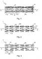
- FIG. 1schematically illustrate a stent in accordance with the invention
- FIG. 2schematically illustrate another stent in accordance with the invention
- FIG. 3schematically illustrate another stent in accordance with the invention.
- FIG. 4schematically illustrate another stent in accordance with the invention.
- FIG. 5schematically illustrate another stent in accordance with the invention.
- FIG. 6schematically illustrate another stent in accordance with the invention.
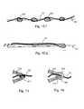
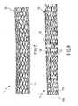
- Figure 7illustrate, in perspective view, the central part of a stent similar to that of figure 1 ;
- Figure 8illustrates, in perspective view, the central part of another stent in accordance with the invention.
- Figure 9illustrates a detail of the stent of figure 7 or 8 ;
- Figure 10illustrate, in perspective view, the central part of a stent similar to that of figure 2 ;
- Figure 11illustrates, in perspective view, another stent in accordance with the invention.
- FIGS 12.a - 12.gschematically illustrate in detail some embodiments of the stent according to the present invention.
- Figure 13schematically illustrates, a detail similar to the detail indicated with XIII in figure 1 ;
- Figure 14schematically illustrates a variant of the detail of figure 13 .
- an endoluminal prosthesis or stentis indicated overall with 1.
- the stent 1can be either of "balloon-expandable” or “self-expandable” type.
- the endoluminal prosthesis 1comprises a tubular body 10 adapted to bring itself from a contracted condition to an expanded or partially expanded condition.
- the stent 1is arranged in contracted condition when it is received or arranged on a transport and implant device (catheter) suitable to go through a duct or vessel up to the zone to be treated.
- a transport and implant devicecatheter
- a stent of self-expandable typeis arranged on a catheter and is contained in sheath which, by radially compressing the stent, keeps it in the contracted state.
- a stent of balloon-expandable typeis arranged in contracted configuration on the deflated balloon of a catheter.
- expanded conditionit is intended a condition in which the stent 1 is radially enlarged, and in use comes into contact with the inner surface of the walls of a duct or vessel.
- the stent 1is arranged in an expanded condition when it is definitively placed in the zone to be treated of a duct or vessel.
- the tubular body 10 of the stent 1is developed along a longitudinal axis X-X.
- longitudinal axisit is intended for example a symmetry axis of a cylindrical body or the axial direction of principal extension of a tubular body.
- the tubular body 10comprises a plurality of bands 11.a, 11.b, 11.c, etc. Such bands define paths which are preferably closed on each other.
- the bands 11are developed along a substantially circumferential direction (indicated with C in figure 1 ).
- the bands 11assume serpentine form.
- serpentine bandit is intended a band which extends according to a zigzag course or backward-forward path around a prevalent extension-direction.
- serpentine bandit is intended a band which extends according to a zigzag course or backward-forward path around a prevalent extension-direction.
- the prevalent directionis that circumferential C around which the zigzag progression extends.
- Each of said serpentine bands 11comprises arm portions, or arms 110, and loop portions, or loops 111, which connect two successive arms 110 to form the meandering path.
- the arms 110are substantially rectilinear and the loops 111 are substantially a circular crown sector.
- the arms 110are shaped along a curved line, for example ⁇ S' shaped.
- At least one thread 13connects at least two bands, for example two adjacent bands such as 11.a and 11.b, or two non-adjacent bands like 11.a and 11.c.
- the threadis composed of a single filament or, preferably, by a plurality of filaments assembled together. Where there is a plurality of filaments, they can be intertwined or twisted together so to remain assembled together.
- the threadcan also comprise an outer covering.
- the mechanical characteristics (stiffness and strength) of the threadare such to permit the same to react in a significant manner only with respect to a traction force along its axis.
- the reactions of the threadare in general negligible with respect to the other possible stresses: compression, twisting, flexion.
- the knotting behaviourcan for example be expressed as a ratio between the inner diameter of a knot made with the thread, momentarily subjected to a determinate traction force, and the nominal diameter of the thread itself.
- a low ratioindicates a thread which is easy to knot (the knot closes well and easily holds).
- a thread with high ratiowill be harder to manage (it is stiffer) and will produce knots which are easier to undo.
- the thread 13has an extension oriented in a substantially axial direction, substantially parallel to the axis X-X.
- the thread 13has a development oriented, in addition to in the axial direction, also in the circumferential direction, so to obtain a helical progression along the stent 1.
- two or more serpentine bandsare connected with each other by means of a single thread portion 13.
- the thread 13is prevalently arranged on the outer surface of the stent 1. In other words, when the stent is situated inside a duct, most of the length of the thread 13 comes into contact with the inner wall of the duct itself.
- the bands 11 of the stent 1are exclusively connected with each other by threads 13.
- the threads 13can connect two adjoining serpentine bands, for example 11.a and 11.b, or two not-immediately adjoining serpentine bands, for example 11.a and 11.c.
- the bands 11 of the stent 1are connected to each other by bridges 12.
- the bridges 12in a known manner, connect the loops 111 of two adjoining serpentine bands, for example 11.a and 11.b.
- the bridges 12are integral and made in one piece with the serpentine bands 11, while the thread is subsequently attached to the stent.
- the threadis flexible and is capable of resisting only the traction forces applied along the X-X axis.
- the bridgesare relatively rigid and are capable of offering resistance to all the forces (both traction and compression) applied along the X-X axis.
- the thread 13is made with a different material than that employed for making the serpentine bands 11.
- the bridges 12are necessarily made with the same material.
- a plurality of threads 13is provided between adjacent serpentine bands, for example 11.a and 11.b.
- every single loop 111 of every single serpentine bandis connected to the respective loop 111 of the adjacent serpentine band, for example 11.a or 11.c.
- the connections between adjacent loopscan be obtained by means of a thread portion 13 or by means of a bridge 12.
- the thread portionhas a slightly tilted direction with respect to the axial direction X-X of the tubular body 10.
- the direction of the thread 13is for example tilted an angle equal to ⁇ with respect to the axial direction X-X.
- all of the threads 13 between two adjacent serpentine bands 11are parallel to each other.
- the bridges 12also have a slightly tilted direction with respect to the axial direction X-X of the tubular body 10.
- the direction of the bridges 12is for example tilted an angle equal to ⁇ with respect to the axial direction X-X.
- bridges 12which are alternated with directions having opposite slopes (respectively + ⁇ and - ⁇ ) with respect to the axial direction X-X.
- the stentcomprises sections 120 comprising in turn several serpentine bands joined together, in a known manner, by bridges 12.
- the sections 120are exclusively connected to each by threads 13 and not by bridges 12.
- each section 120can identify three sections 120, each one comprising two serpentine bands.
- the number of sections 120 and/or serpentine bands for each sectioncan be chosen differently, in consideration of specific needs..
- the number of serpentine bands 11 for each section 120can increase along the axis X-X from the proximal end towards the centre of the stent 1. Once the maximum number of serpentine bands 11 is reached in the central section 120, the number of serpentine bands for each section can once again decrease along the X-X axis from the centre of the stent towards the distal end.
- the threads 13 attached to the stent 1have different lengths. Each thread is applied so to cover the central portion of the stent 1. In this manner one obtains a quantity of threads 13 which increases along the axis X-X from the proximal end towards the centre of the stent 1. Once the maximum has been reached in the central portion, the number of threads 13 once again decreases along the X-X axis from the centre of the stent towards the distal end.
- the bands of the stentare composed of curls 11' of a single, long helical serpentine band 113.
- the progression of the serpentine band 113does not oscillate around a circumferential direction closed on itself but around a helix, for example cylindrical, which runs through the entire body 10 of the stent 1.
- the curls 11' created by the helical serpentine band 113diverge little from the progression of the serpentine bands 11 described above and thus they substantially maintain the circumferential direction, swaying little from it.
- the curls 11' of the helical serpentine band 113are not connected with each other by bridges 12 but only by threads 13. In accordance with other possible embodiments, the curls 11' can be also connected with each other by bridges 12.
- the loops 111 to which a thread 13 is associatedcomprise grasping enhancers 115.
- the grasping enhancers 115are geometric alterations of the loop made so to have more solid and secure grasping of the thread 13. on the loop 111.
- the grasping enhancers 115comprise a slot 116 in which the thread 13 is made to pass.
- the grasping enhancers 115are therefore intended to give place to a form coupling between the loop 111 and the respective thread 13.
- the form couplingcan be obtained on a macroscopic scale, as in the examples listed above, or on a more reduced scale.
- the form couplingcan be obtained for example by means of surface grooves of the loop 111 or by means of a high porosity of the same. This could be useful for gluing the thread.
- the form couplingtherefore ensures that the grasping of the thread 13 on the serpentine band 11 is more effective and reliable.
- the serpentine bands 11 and the bridges 12, when said stent 1 is of self-expandable type,are in superelastic material.
- the serpentine bands 11 and the bridges 12are in a hardened pseudo-elastic material.
- a material which is in austenitic state at room temperaturei.e. it has a high temperature of end transformation into austenite Af: less than 15°C
- a sufficient hardening treatmentis applied equal to 50%.
- the above identified materialwill be referred to below with the expression “superelastic material” .
- said serpentine bands 11 and said bridges 12are in a so-called shape memory material.
- said serpentine bands 11 and said bridges 12are in Nitinol, or Nickel and Titanium - based alloy, for example with nominal percentage by weight of Nickel of 55.8%.
- the serpentine bands 11 and the bridges 12, when said stent is of balloon-expandable type,are in stainless steel.
- a stainless steel of the type classified as AISI 316 Laccording to the standards of the American Iron and Steel Institute.
- This alloy of stainless steelhas the following standard chemical weight composition: Carbon 0.035%, Phosphorus 0.04%, Sulphur 0.03%, Manganese 2%, Silicon 0.75%, Chromium 16-18%, Nickel 10-15%, Molybdenum 2-3% and Iron to balance.
- the above identified alloywill be referred to below with the expression "stainless steel”.
- the serpentine bands 11 and the bridges 12, when said stent is of balloon-expandable type,are in a non-magnetic alloy of Nickel-Cobalt-Chromium-Molybdenum for surgical implants.
- an alloy of the type classified as UNS R30035according to the Unified Numbering System for Metals and Alloys.
- Such alloyhas the following standard composition: Carbon maximum 0.025%, Phosphorus max 0.015%, Sulphur max 0.01%, Manganese max 0.15%, Silicon max 0.15%, Chromium 19-21%, Nickel 33-37%, Molybdenum 9-11%, Titanium max 1%, Boron max 0.01%, Iron max 1% and Cobalt to balance.
- the serpentine bands 11 and the bridges of said stent 1are obtained from the cutting of a tubular element, preferably by means of laser cutting.
- the serpentine bands 11 and the bridges 12are made integrally from a tubular element by means of cutting, for example laser cutting.
- serpentine bands 11 and the bridges 12are made according to the invention are enduring materials.
- the serpentine bands 11 and the bridges 12 according to the invention made of superelastic material, in Nitinol, in stainless steel or in Chromium-Cobalt alloyremain nearly unaltered in their dimensions and in the geometries during the operation life in the vessel or duct in which they have been implanted.
- the threads 13can be made of an enduring material or of a material which is commonly defined as biodegradable, bioerodable or preferably bioabsorbable.
- the bioabsorbable material with which each thread 13 is madehas the property of dissolving itself in the natural contents of the vessel or duct in which the stent is placed (for example in the blood contained in the vessels)
- the phenomenon which leads the bioabsorbable material to dissolve itselfcan be of chemical, electrochemical or physical nature according to the type of material used.
- the thread 13 or the filaments which compose itare made with enduring polymers, such as for example polyamide (PA) and/or polytetrafluoroethylene (PTFE).
- enduring polymerssuch as for example polyamide (PA) and/or polytetrafluoroethylene (PTFE).
- PApolyamide
- PTFEpolytetrafluoroethylene
- Such polymersare available on the market with the commercial names of Nylon and Teflon, respectively.
- the thread 13 or filaments which compose itare made with a bioabsorbable polymer.
- Bioabsorbable polymers particularly adapted for use in the present inventionare: PDLA or poly-(D-lactic acid), PLLA or poly-(L-lactic acid), PGA or poly-(glycolic acid).
- bioabsorbable polymersadapted for use are the following: poly-caprolactone, poly-(lactide-co-glycolide), poly-(ethylene-vinyl acetate), poly-(hydroxybutyrate-co-valerate), poly-dioxanone, poly-orthoester, poly-anhydride, poly-(glycolic acid-co-trimethylene carbonate), poly-phosphoester, poly-phosphoester urethane, poly(amino acids), cyanoacrylates, poly-(trimethylene carbonate), poly-(iminocarbonate), copoly-(ether-esters) (e.g.,
- PEO/PLApoly-alkylene oxalates
- poly-phosphazenesand biomolecules such as fibrin, fibrinogen, cellulose, starch, collagen, hyaluronic acid, poly-N-alkylacrylamides, poly-depsi-peptide carbonate, and poly-ethylene-oxide based ploy-esters.
- the threads 13 in bioabsorbable polymercan be produced by means of the typical working technologies of this type of polymer.
- the polymer thread 13 and/or filamentscan advantageously be produced, in a known manner, by means of one of the different types of extrusion spinning (wet, dry, in melted state or in gel) or by means of any other technological process which permits satisfying specific needs.
- the structure of the thread 13can be monofilament or, starting from a plurality of filaments, it can be intertwined or twisted, with or without outer covering.
- connection between the thread 13 in bioabsorbable polymer and the serpentine band 11 in enduring materialcan be obtained in various modes.
- connection formcomprises a knot 130 carried out with the thread 13 around a section of a serpentine band 11, independently from the presence of grasping enhancers 115.
- connection formcomprises a winding 131 executed with the thread 13 around a section of a serpentine band 11, without forming an actual knot 130.
- a further connection form(see for example figure 12.c ) comprises a gluing 132 of the thread 13 on the serpentine band 11.
- the polymer used for the gluing 132can be the same with which the thread is made or another of the abovementioned bioabsorbable polymers, according to specific needs.
- a preferred connection form of a thread 13 to a stent 1comprises a mixed use of the above-described connection forms. For example, it is possible to knot the thread 13 at a first serpentine band 11.a (proximal end) and then wind it or paste it on the subsequent serpentine bands 11.b, 11.c, etc. without additional knots, but on the last serpentine band (distal end).
- the threads 13are made with bioabsorbable metal materials.
- the thread 13is made with a Magnesium alloy.
- an alloy of the type classified as UNS M18430according to the Unified Numbering System for Metals and Alloys.
- Such alloyhas the following composition standard: Yttrium 3.7-4.3%, Rare Earths 2.4-4.4% (the Rare Earths consist of Neodymium 2.0-2.5%, the rest being heavy Rare Earths, mainly Ytterbium, Erbium, Dysprosium and Gadolinium), Zirconium min 0.4%, and Magnesium to balance.
- the threads 13 in Magnesium alloycan be made by means of any one of the typical working technologies of this alloy type.
- the threads 13 in Magnesium alloycan be advantageously made by means of drawing, by means of extrusion, by means of hot or cold moulding, by means of sintering, by means of laser working or by means of any other technological process which permits satisfying the specific needs.
- the connection between the Magnesium alloy thread 13 and the serpentine band 11can be obtained, independently from the presence of the grasping enhancers 115, for example by means of welding or gluing, or by intertwining the thread between the various serpentine bands, according to specific needs.
- the weldingcan be carried out with a protective atmosphere technology (for example with TIG technology, Tungsten Inert Gas).
- the polymer used as gluecan be one of the bioabsorbable polymers listed above.
- the thread 13is made with a binary mixture of Calcium Oxide (CaO) and Phosphorus Pentoxide (P 2 O 5 ).
- a binary mixturewith 5-50% Calcium Oxide (CaO) and 50-95% Phosphorus Pentoxide (P 2 O 5 ).
- the binary mixtureis composed of 15-25% Calcium Oxide (CaO) and 65-85% Phosphorus Pentoxide (P 2 O 5 ).
- Such binary mixturecan also contain small quantities of Calcium Fluoride (CaF 2 ), water (H 2 O) and other oxides of Magnesium, Zinc, Strontium, Sodium, Potassium, Lithium or Aluminium.
- the threads 13 in Calcium-Phosphorus mixturecan be made by means of any one the typical working technologies of this material type.
- the threads 13 in Calcium-Phosphorus mixturecan be advantageously made by means of drawing, extrusion, melting, hot moulding or any other technological process which permits satisfying specific needs.
- connection between the thread 13 in Calcium-Phosphorus mixture and the serpentine band 11can be obtained, independently from the presence of the grasping enhancers 115, for example, by means of welding or gluing, or by intertwining the thread 13 between the various serpentine bands 11, according to the specific needs.
- the polymer used as gluecan be used as a bioabsorbable polymer of those listed above.
- a single thread 13is arranged along the stent 1, preferably along the entire length, or rather along its entire longitudinal length.
- the thread 13is a structure which has a predominantly axial extension and which joins more than two serpentine bands 11.
- a plurality of threads 13is present, as shown schematically in figures 1-3 and 6 .
- an end serpentine band(for example the serpentine 11.a placed at the distal end) comprises a marker made in radiopaque material.
- the serpentine bands 11 of the stent 1are made, for example, in superelastic material or in Nitinol and the threads 13 are made, for example, in polymer material, the stent would be entirely invisible to the radioscopy.
- a stent which is not visible to the radioscopyposes very serious problems to the operator who must implant it in a patient using the conventional - radioscopic apparatus to follow the movements and positioning of the stent along the vessels of the patient.
- the radiopaque material with which the marker is madecan be chosen from Tantalum, Gold, Platinum, Tungsten or other materials suitable for such purpose.
- both serpentine bands placed at the distal and proximal end of the stent 1, i.e. and the first and the last serpentine bandrespectively comprise at least one radiopaque marker.
- the thread 13 made of bioabsorbable materialis adapted to release a drug in a controlled manner and prolonged over time.
- the threads 13can be previously treated so to be porous. In the pores of the bioabsorbable material, a pharmacologically active substance can be inserted which is adapted for the treatment of the zone in which the stent 1 is implanted.
- radial forcedescribes the capacity of the stent to resist circumferential loads. It is definable as the radial force which the stent is capable of exerting inside a vessel once it has been correctly implanted therein.
- the radial forcedepends on the geometry and above all on the elastic modulus E of the employed material. The higher the value of the elastic modulus, the greater the radial force which can be obtained by the stent.
- 'recoil'A further important characteristic in the evaluation of a balloon-expandable stent is called 'recoil'.
- the recoilis, in percentage, the elastic return of the stent following the expansion. In fact, during the expansion, the stent is over-expanded to take into account the inevitable elastic return.
- a low recoilin addition to an appropriate geometry of the stent, can be obtained due to a high elastic modulus E and to a not overly high yield strength ⁇ 0.2 .
- the present inventionby permitting the use of different materials inside the same endoluminal prosthesis, permits the designer to balance the characteristics of one material with that of another.
- the stent 1 described above according to the inventioncan resolve the problem of sustaining the vessel wall more immediately after the implant, and then reducing the effect over a long period.
- both the serpentine band and the bridges and threadscontribute to supporting the walls of the vessel. Subsequently, once the acute phase is terminated, the bioabsorbable threads are dissolved, for example in the blood, and there remain only the parts in enduring material (the serpentine bands and the bridges, if present) therefore limiting the stress on the wall.
- the presence of the thread 13 at the time of the stent implantinhibits the jumping ahead phenomenon of the stent at the time of release. In fact, the thread 13 blocks the stent 1 from suddenly expanding at the time of the removal from the sheath.
- the presence of the threads 13 in the first phases of the stent implant and in the immediately following phasesensures an optimal positioning of the stent in its entirety and ensures that the single serpentine bands assume a correct position with respect to each other.
- each loopis connected to the adjacent loop permits the operator, during the operation, to adjust the position of the stent along the vessel wherein it is to be implanted.
- This operationis made possible by the particular conformation in which a bridge 12 or a thread 13 is provided for each loop 111.
- Such conformationpermits perfectly connecting the serpentine bands which had already been uncovered by the withdrawal of the sheath with the serpentine bands which are still covered by the sheath. This characteristic permits the operator to re-push the sheath ahead along the catheter, and along the stent 1, so to close the serpentine bands which were previously open.
- the stent 1also comprises at least one thread 13' which has a length greater than double the catheter employed for the positioning of the stent in the duct inside the human body.
- the thread 13'is wound without any knot around a serpentine band of the stent 1.
- the thread 13'is passed along its entire length so that both of its ends are reachable at the proximal end of the catheter itself.
- the operatorcan apply a traction action on the stent and can therefore maintain greater control during the delicate positioning step.
- the thread 13'can be unthreaded by pulling on one of the two ends.
- serpentine bands 11, arms 110 and loops 111can vary with respect to what described and illustrated. Also the form of the serpentine bands can vary.
Landscapes
- Health & Medical Sciences (AREA)
- Engineering & Computer Science (AREA)
- Biomedical Technology (AREA)
- Life Sciences & Earth Sciences (AREA)
- Veterinary Medicine (AREA)
- Public Health (AREA)
- General Health & Medical Sciences (AREA)
- Animal Behavior & Ethology (AREA)
- Heart & Thoracic Surgery (AREA)
- Vascular Medicine (AREA)
- Cardiology (AREA)
- Transplantation (AREA)
- Oral & Maxillofacial Surgery (AREA)
- Physics & Mathematics (AREA)
- Optics & Photonics (AREA)
- Surgery (AREA)
- Epidemiology (AREA)
- Prostheses (AREA)
- Media Introduction/Drainage Providing Device (AREA)
- Materials For Medical Uses (AREA)
Abstract
Description
- Forming the object of the present invention is an endoluminal prosthesis, or stent, for use in passages or ducts of living bodies, above all the human body. Such endoluminal prosthesis can be used, for example, for restoring the passage sin blood vessels reduced or obstructed by pathological phenomena such as a stenosis. Such endoluminal prosthesis can also be used in bile ducts or other similar organs.
- The present:invention refers to a type of endoluminal prosthesis which is positioned in a radially contracted state inside the selected duct. Once in place, the prosthesis is brought into expanded state, until it reaches the suitable size for the duct.
- Documents
WO2006/034062 andWO2006/058206 disclose devices having anchors which can be used to secure tubes within a digestive truck. Each anchor connected with the near one with a joining member. DocumentWO2008/030488 andWO9413268 - . For some types of endoluminal prostheses called "balloon-expandable", the expansion step is usually completed by applying a radial pressure from the interior, Such pressure is generally applied by means of an element, called ball, which, can be radially expanded by means of the insertion of a fluid under pressure.
- . Such "balloon-expandable" prostheses are made, for example, with stainless steel or with chrome-cobalt alloys.
- . Other endoluminal prosthesis types called "self-expandable", are made so to spontaneously take on an expanded configuration The expansion step is usually completed by releasing the prosthesis from a radial constriction.
- Such "self-expandable" prosthesis are made, for example, of superelastic materials or with shape memory materials, such as Nitinol.
- The known endoluminal prostheses or stents are generally formed by a succession of bands arranged next to each other in axial direction and connected to each other by means of bridges. The bands are radially contractible and expandable. In turn, the bridges are often elastic in the axial and circumferential direction.
- . Due to this structure, above all thanks to the radially contractible and expandable bands, the stent is capable firstly of assuming a contracted configuration and an expanded configuration. Moreover the stent, due above all to the elastic bridges in the axial and circumferential direction, is capable of following all of the movements and deformations of the vessel during its operation life.
- . These endoluminal prostheses, while satisfactory from many standpoints, in particular for their great flexibility and elasticity, which permit easily slipping the prosthesis in contracted state into narrow and tortuous passages, are in turn not sufficiently adapted, in the operating life, for supporting the continuous stress applied by the vessel walls.
- . In particular, the stresses which are most dangerous for the prosthesis are the "fatigue" stresses, i.e. those stresses which derive from loads which can vary over time. Such stresses translate into a state of strain oscillating around an average value.
- . In general, the fatigue stresses can lead a mechanical piece to failure or breaking, even if during the operation life a strain peak is never registered which exceeds the static breaking limit of the piece itself.
- . In the specific case of the endoluminal prostheses or stents, the fatigue stresses become particularly dangerous for the bridges which join the bands together.
- . Notwithstanding the severe tests to which the stents must be subjected in order to be used in the care of human patients, it is unfortunately possible that a bridge breaking occurs due to fatigue.
- . The bridge breaking originates two stumps and two fracture surface. The two stumps, no longer connected with each other, are much less flexible than the entire bridge and are less adapted to follow the deformations of the vessel walls on which they lie.
- . In addition, the two fracture surfaces do not have the characteristics of the other stent surfaces, suitably treated in the production step to come into contact with the vessel walls. Often, moreover, the fracture surface have sharp, if not cutting edges.
- . It is therefore clear that the occurrence of a similar fracture translates into a dangerous stress of the vessel wall. Such stress is dangerous since it could soon lead, in the worst cases, to the perforation of the wall. In less serious cases, in the long term, it could lead to a local thickening of the wall, undoing the effect which had been originally intended by installing the stent.
- . Stents of known type have a further problem. The implant time of the stent represents an acute step of stress of the vessel wall, which therefore requires a great support. A stent of traditional type, developed for optimising the support during this first acute step, then risks not ensuring good behaviour during the subsequent chronic step. In such step, in fact, the necessary support is widely reduced and an excessive quantity of metal inside the vessel risks representing a constant stress factor for the wall.
- . The known stents, above all of "self-expandable" type finally have one other problem. During the release step inside the vessel, when the sheath which provides the radial constriction is pulled back, there is an elongation of the stent. Such elongation can cause on the one hand a longitudinal stress of the vessel, and on the other hand an actual jump ahead of the stent along the vessel. The jump ahead represents a big problem for the correct positioning of the stent itself.
- . The operator which carries out the operation can in fact be fooled by this hard-to-predict behaviour of the stent. The search of the correct positioning of the stent can be made futile by the latter's jump ahead at the moment of the release.
- . The object of the present invention is that of proposing an endoluminal prosthesis, which has structural and functional characteristics so to at least partially overcome the aforesaid drawbacks mentioned with reference to the prior art.
- . In particular, a task of the present invention is that of proposing an endoluminal prosthesis which permits providing a greater support immediately after the implant and slowly reducing it during the operation life.
- . In particular, a task of the present invention is that of proposing an endoluminal prosthesis, which drastically reduces the fatigue breaking.
- . In particolare, a task of the present invention is that of proposing an endoluminal prosthesis which resolves the problem deriving from the elongation and from the consequent jump which occurs during the release step.
- . Such object and such tasks are attained by means of an endoluminal prosthesis of the type described in
claim 1. - . Further embodiments are described in the dependent claims.
- . Further characteristics and advantages of the prosthesis according to the invention result from the following description of its preferred embodiments, given as indicative and non-limiting, with reference to the attached figures; wherein:
- .
Figure 1 schematically illustrate a stent in accordance with the invention; - .
Figure 2 schematically illustrate another stent in accordance with the invention; - .
Figure 3 schematically illustrate another stent in accordance with the invention; - .
Figure 4 schematically illustrate another stent in accordance with the invention; - .
Figure 5 schematically illustrate another stent in accordance with the invention; - .
Figure 6 schematically illustrate another stent in accordance with the invention; - .
Figure 7 illustrate, in perspective view, the central part of a stent similar to that offigure 1 ; - .
Figure 8 illustrates, in perspective view, the central part of another stent in accordance with the invention; - .
Figure 9 illustrates a detail of the stent offigure 7 or 8 ; - .
Figure 10 illustrate, in perspective view, the central part of a stent similar to that offigure 2 ; - .
Figure 11 illustrates, in perspective view, another stent in accordance with the invention; - .
Figures 12.a - 12.g schematically illustrate in detail some embodiments of the stent according to the present invention; - .
Figure 13 schematically illustrates, a detail similar to the detail indicated with XIII infigure 1 ; - .
Figure 14 schematically illustrates a variant of the detail offigure 13 . - . With reference to the aforesaid figures, an endoluminal prosthesis or stent is indicated overall with 1. The
stent 1 can be either of "balloon-expandable" or "self-expandable" type. - . In accordance with a general form of the present invention, the
endoluminal prosthesis 1, comprises atubular body 10 adapted to bring itself from a contracted condition to an expanded or partially expanded condition. - . With the term "contracted condition" it is intended a radially-compressed state of the
stent 1, so to have a lower outer diameter and a lower radial size with respect to those of use. - . For example, the
stent 1 is arranged in contracted condition when it is received or arranged on a transport and implant device (catheter) suitable to go through a duct or vessel up to the zone to be treated. - . For example, a stent of self-expandable type is arranged on a catheter and is contained in sheath which, by radially compressing the stent, keeps it in the contracted state.
- . A stent of balloon-expandable type is arranged in contracted configuration on the deflated balloon of a catheter.
- . With the term "expanded condition", it is intended a condition in which the
stent 1 is radially enlarged, and in use comes into contact with the inner surface of the walls of a duct or vessel. - . For example, the
stent 1 is arranged in an expanded condition when it is definitively placed in the zone to be treated of a duct or vessel. - . For example, in the case of a self-expandable stent, once the
stent 1 is brought into place by means of the catheter, the sheath which radially compresses it is removed and thestent 1 spontaneously passes to its expanded condition. - . In the case of a balloon-expandable stent, on the other hand, once the
stent 1 is brought into place by means of the catheter, the balloon is inflated. By pressing radially on the inside of thestent 1, the balloon brings thestent 1 to its expanded condition. - . The
tubular body 10 of thestent 1 is developed along a longitudinal axis X-X. - . With "longitudinal axis" it is intended for example a symmetry axis of a cylindrical body or the axial direction of principal extension of a tubular body.
- . Every direction parallel to the X-X axis of therefore defined as axial direction.
- . As schematically indicated in
figure 1 , thetubular body 10 comprises a plurality of bands 11.a, 11.b, 11.c, etc. Such bands define paths which are preferably closed on each other. In the embodiments represented in the attached figures, when thestent 1 is in expanded condition, thebands 11 are developed along a substantially circumferential direction (indicated with C infigure 1 ). - . Moreover, in the
stent 1 of the attached figures, thebands 11 assume serpentine form. - . With "serpentine band" it is intended a band which extends according to a zigzag course or backward-forward path around a prevalent extension-direction. In the case of the serpentine bands which form the
stent 1 represented in the attached figures, the prevalent direction is that circumferential C around which the zigzag progression extends. - . Each of said
serpentine bands 11 comprises arm portions, orarms 110, and loop portions, orloops 111, which connect twosuccessive arms 110 to form the meandering path. - . In accordance with the embodiment schematically represented in
figure 13 , thearms 110 are substantially rectilinear and theloops 111 are substantially a circular crown sector. - . In accordance with another embodiment, the
arms 110 are shaped along a curved line, for example `S' shaped. - . At least one
thread 13 connects at least two bands, for example two adjacent bands such as 11.a and 11.b, or two non-adjacent bands like 11.a and 11.c. - . With "thread" it is intended an elongated and extremely flexible element. Defining a proper axis of the thread, the characteristic dimensions of any cross section perpendicular to the proper axis are in general negligible with respect to the third dimension along the axis. The thread is composed of a single filament or, preferably, by a plurality of filaments assembled together. Where there is a plurality of filaments, they can be intertwined or twisted together so to remain assembled together. The thread can also comprise an outer covering.
- . In general, the mechanical characteristics (stiffness and strength) of the thread are such to permit the same to react in a significant manner only with respect to a traction force along its axis. On the other hand, the reactions of the thread are in general negligible with respect to the other possible stresses: compression, twisting, flexion.
- . The person skilled in the art will understand from the foregoing the differences between the thread as described and other elongated structures (bars, rods, staffs and the like) of comparable dimensions.
- . From the foregoing, it can be deduced, for example, how the thread is an element characterised by a good knotting behaviour.
- . The knotting behaviour can for example be expressed as a ratio between the inner diameter of a knot made with the thread, momentarily subjected to a determinate traction force, and the nominal diameter of the thread itself. A low ratio indicates a thread which is easy to knot (the knot closes well and easily holds). A thread with high ratio will be harder to manage (it is stiffer) and will produce knots which are easier to undo.
- . In accordance with the embodiments of the
stent 1 schematically represented in thefigures 1-3 and5-6 , thethread 13 has an extension oriented in a substantially axial direction, substantially parallel to the axis X-X. - . In accordance with other embodiments, for example that represented schematically in
figure 4 , thethread 13 has a development oriented, in addition to in the axial direction, also in the circumferential direction, so to obtain a helical progression along thestent 1. - . In accordance with other embodiments of the
stent 1 according to the invention (for example the embodiments represented infigures 1-2 and4-6 ), two or more serpentine bands are connected with each other by means of asingle thread portion 13. - . In accordance with several embodiments, the
thread 13 is prevalently arranged on the outer surface of thestent 1. In other words, when the stent is situated inside a duct, most of the length of thethread 13 comes into contact with the inner wall of the duct itself. - . In accordance with several embodiments (see for example
figure 2 ), thebands 11 of thestent 1 are exclusively connected with each other bythreads 13. - . The
threads 13 can connect two adjoining serpentine bands, for example 11.a and 11.b, or two not-immediately adjoining serpentine bands, for example 11.a and 11.c. - . In accordance with several embodiments (see for example
figures 1 ,3-6 ), thebands 11 of thestent 1 are connected to each other bybridges 12. - . The
bridges 12, in a known manner, connect theloops 111 of two adjoining serpentine bands, for example 11.a and 11.b. - . There are some important differences between the
bridges 12 and thethread 13. First, thebridges 12 are integral and made in one piece with theserpentine bands 11, while the thread is subsequently attached to the stent. - . Moreover, the thread is flexible and is capable of resisting only the traction forces applied along the X-X axis. On the other hand, the bridges are relatively rigid and are capable of offering resistance to all the forces (both traction and compression) applied along the X-X axis.
- . Finally, the
thread 13 is made with a different material than that employed for making theserpentine bands 11. On the other hand, thebridges 12 are necessarily made with the same material. - . The materials employed for the different structures (bands or
serpentine bands 11, bridges 12 and thread 13) will be described in detail below. - . Advantageously, between adjacent serpentine bands, for example 11.a and 11.b, a plurality of
threads 13 is provided. - . In accordance with the embodiment represented in
figure 7 , everysingle loop 111 of every single serpentine band, for example 11.b, is connected to therespective loop 111 of the adjacent serpentine band, for example 11.a or 11.c. The connections between adjacent loops can be obtained by means of athread portion 13 or by means of abridge 12. - . In accordance with the embodiment represented in
figure 4 , the thread portion has a slightly tilted direction with respect to the axial direction X-X of thetubular body 10. The direction of thethread 13 is for example tilted an angle equal to ±α with respect to the axial direction X-X. - . Preferably, all of the
threads 13 between two adjacentserpentine bands 11 are parallel to each other. - . In accordance with the embodiment schematically represented in
figure 5 , thebridges 12 also have a slightly tilted direction with respect to the axial direction X-X of thetubular body 10. The direction of thebridges 12 is for example tilted an angle equal to ±β with respect to the axial direction X-X. - . In particular, in the embodiment of
figure 5 , following thestent 1 longitudinally, for example going from a first proximal end to a second distal end of the stent, there arebridges 12 which are alternated with directions having opposite slopes (respectively +β and - β) with respect to the axial direction X-X. - . In accordance with an embodiment schematically represented in
figure 3 , the stent comprisessections 120 comprising in turn several serpentine bands joined together, in a known manner, by bridges 12. Thesections 120, on the other hand, are exclusively connected to each bythreads 13 and not bybridges 12. - . In the particular embodiment schematised in
figure 3 , one can identify threesections 120, each one comprising two serpentine bands. In accordance with other possible embodiments, the number ofsections 120 and/or serpentine bands for each section can be chosen differently, in consideration of specific needs.. - . For example, the number of
serpentine bands 11 for eachsection 120 can increase along the axis X-X from the proximal end towards the centre of thestent 1. Once the maximum number ofserpentine bands 11 is reached in thecentral section 120, the number of serpentine bands for each section can once again decrease along the X-X axis from the centre of the stent towards the distal end. - . In the particular embodiment schematised in
figure 6 , it can be observed that thethreads 13 attached to thestent 1 have different lengths. Each thread is applied so to cover the central portion of thestent 1. In this manner one obtains a quantity ofthreads 13 which increases along the axis X-X from the proximal end towards the centre of thestent 1. Once the maximum has been reached in the central portion, the number ofthreads 13 once again decreases along the X-X axis from the centre of the stent towards the distal end. - . In the particular embodiment schematised in
figure 11 , it can be observed that the bands of the stent are composed of curls 11' of a single, long helicalserpentine band 113. In this case, the progression of theserpentine band 113 does not oscillate around a circumferential direction closed on itself but around a helix, for example cylindrical, which runs through theentire body 10 of thestent 1. The curls 11' created by the helicalserpentine band 113 diverge little from the progression of theserpentine bands 11 described above and thus they substantially maintain the circumferential direction, swaying little from it. - . In accordance with the embodiment of
figure 11 , the curls 11' of the helicalserpentine band 113 are not connected with each other bybridges 12 but only bythreads 13. In accordance with other possible embodiments, the curls 11' can be also connected with each other bybridges 12. - . In accordance with the embodiment of the
stent 1 according to the invention represented infigure 14 , at least some of theloops 111 to which athread 13 is associated, comprise graspingenhancers 115. The graspingenhancers 115 are geometric alterations of the loop made so to have more solid and secure grasping of thethread 13. on theloop 111. - . In accordance with the embodiment represented in
figure 14 , the graspingenhancers 115 comprise aslot 116 in which thethread 13 is made to pass. - . The grasping
enhancers 115 are therefore intended to give place to a form coupling between theloop 111 and therespective thread 13. - . The form coupling can be obtained on a macroscopic scale, as in the examples listed above, or on a more reduced scale. The form coupling can be obtained for example by means of surface grooves of the
loop 111 or by means of a high porosity of the same. This could be useful for gluing the thread. - . The form coupling therefore ensures that the grasping of the
thread 13 on theserpentine band 11 is more effective and reliable. - . Advantageously, the
serpentine bands 11 and thebridges 12, when saidstent 1 is of self-expandable type, are in superelastic material. In accordance with a different embodiment, theserpentine bands 11 and thebridges 12 are in a hardened pseudo-elastic material. - . In other words, it is possible to use a material which is in austenitic state at room temperature (i.e. it has a high temperature of end transformation into austenite Af: less than 15°C) when annealed, to which a sufficient hardening treatment followed, for example greater than 30%, which permits having an elastic deformation recovery of 3%-4% or greater. Preferably, a hardening treatment is applied equal to 50%. For simplicity, the above identified material will be referred to below with the expression "superelastic material".
- . In accordance with one embodiment, said
serpentine bands 11 and saidbridges 12 are in a so-called shape memory material. - . Advantageously, said
serpentine bands 11 and saidbridges 12 are in Nitinol, or Nickel and Titanium - based alloy, for example with nominal percentage by weight of Nickel of 55.8%. - . For example, it is possible to use a material having austenite-martensite phase transition in which, if in annealed or stretched state, during a heating thereof, the high temperature of end transformation into austenite Af is less than 15°C. For simplicity, the above identified alloy will be referred to below with the expression "Nitinol".
- . Advantageously, the
serpentine bands 11 and thebridges 12, when said stent is of balloon-expandable type, are in stainless steel. - . For example, it is possible to employ a stainless steel of the type classified as AISI 316 L according to the standards of the American Iron and Steel Institute. This alloy of stainless steel has the following standard chemical weight composition: Carbon 0.035%, Phosphorus 0.04%, Sulphur 0.03%, Manganese 2%, Silicon 0.75%, Chromium 16-18%, Nickel 10-15%, Molybdenum 2-3% and Iron to balance. For simplicity, the above identified alloy will be referred to below with the expression "stainless steel".
- . Advantageously, the
serpentine bands 11 and thebridges 12, when said stent is of balloon-expandable type, are in a non-magnetic alloy of Nickel-Cobalt-Chromium-Molybdenum for surgical implants. - . For example, it is possible to employ an alloy of the type classified as UNS R30035 according to the Unified Numbering System for Metals and Alloys. Such alloy has the following standard composition: Carbon maximum 0.025%, Phosphorus max 0.015%, Sulphur max 0.01%, Manganese max 0.15%, Silicon max 0.15%, Chromium 19-21%, Nickel 33-37%, Molybdenum 9-11%,
Titanium max 1%, Boron max 0.01%,Iron max 1% and Cobalt to balance. - . An alloy of this type is commercialised with the name "Carpenter MP35N" which is a trademark of SPS Technologies, Inc. For simplicity, the above identified alloy will be referred to below, with the expression "Chromium-Cobalt alloy".
- . In accordance with one embodiment, the
serpentine bands 11 and the bridges of saidstent 1 are obtained from the cutting of a tubular element, preferably by means of laser cutting. - . According to one possible embodiment, the
serpentine bands 11 and thebridges 12 are made integrally from a tubular element by means of cutting, for example laser cutting. - . The materials described up to now with which the
serpentine bands 11 and thebridges 12 are made according to the invention are enduring materials. In other words, theserpentine bands 11 and thebridges 12 according to the invention made of superelastic material, in Nitinol, in stainless steel or in Chromium-Cobalt alloy remain nearly unaltered in their dimensions and in the geometries during the operation life in the vessel or duct in which they have been implanted. - . The
threads 13 can be made of an enduring material or of a material which is commonly defined as biodegradable, bioerodable or preferably bioabsorbable. In other words, the bioabsorbable material with which eachthread 13 is made has the property of dissolving itself in the natural contents of the vessel or duct in which the stent is placed (for example in the blood contained in the vessels) The phenomenon which leads the bioabsorbable material to dissolve itself can be of chemical, electrochemical or physical nature according to the type of material used. - . In accordance with one embodiment of the invention, the
thread 13 or the filaments which compose it are made with enduring polymers, such as for example polyamide (PA) and/or polytetrafluoroethylene (PTFE). Such polymers are available on the market with the commercial names of Nylon and Teflon, respectively. - . In accordance with one embodiment of the invention, the
thread 13 or filaments which compose it are made with a bioabsorbable polymer. Bioabsorbable polymers particularly adapted for use in the present invention are: PDLA or poly-(D-lactic acid), PLLA or poly-(L-lactic acid), PGA or poly-(glycolic acid). - . Further bioabsorbable polymers adapted for use are the following: poly-caprolactone, poly-(lactide-co-glycolide), poly-(ethylene-vinyl acetate), poly-(hydroxybutyrate-co-valerate), poly-dioxanone, poly-orthoester, poly-anhydride, poly-(glycolic acid-co-trimethylene carbonate), poly-phosphoester, poly-phosphoester urethane, poly(amino acids), cyanoacrylates, poly-(trimethylene carbonate), poly-(iminocarbonate), copoly-(ether-esters) (e.g. PEO/PLA), poly-alkylene oxalates, poly-phosphazenes and biomolecules such as fibrin, fibrinogen, cellulose, starch, collagen, hyaluronic acid, poly-N-alkylacrylamides, poly-depsi-peptide carbonate, and poly-ethylene-oxide based ploy-esters.
- . The
threads 13 in bioabsorbable polymer can be produced by means of the typical working technologies of this type of polymer. For example, thepolymer thread 13 and/or filaments can advantageously be produced, in a known manner, by means of one of the different types of extrusion spinning (wet, dry, in melted state or in gel) or by means of any other technological process which permits satisfying specific needs. - . In a known manner, the structure of the
thread 13 can be monofilament or, starting from a plurality of filaments, it can be intertwined or twisted, with or without outer covering. - . The connection between the
thread 13 in bioabsorbable polymer and theserpentine band 11 in enduring material can be obtained in various modes. - . One connection form comprises a
knot 130 carried out with thethread 13 around a section of aserpentine band 11, independently from the presence of graspingenhancers 115. - . Another connection form comprises a winding 131 executed with the
thread 13 around a section of aserpentine band 11, without forming anactual knot 130. - . Several examples of connection by means of
knots 130 orwindings 131 are schematically represented in thefigures 12 . - . Finally, a further connection form (see for example
figure 12.c ) comprises a gluing 132 of thethread 13 on theserpentine band 11. The polymer used for the gluing 132 can be the same with which the thread is made or another of the abovementioned bioabsorbable polymers, according to specific needs. - . Practically speaking, a preferred connection form of a
thread 13 to astent 1 comprises a mixed use of the above-described connection forms. For example, it is possible to knot thethread 13 at a first serpentine band 11.a (proximal end) and then wind it or paste it on the subsequent serpentine bands 11.b, 11.c, etc. without additional knots, but on the last serpentine band (distal end). - . In accordance with some embodiments, the
threads 13 are made with bioabsorbable metal materials. - . In accordance with one possible embodiment, the
thread 13 is made with a Magnesium alloy. - . For example, it is possible to employ an alloy of the type classified as UNS M18430 according to the Unified Numbering System for Metals and Alloys. Such alloy has the following composition standard: Yttrium 3.7-4.3%, Rare Earths 2.4-4.4% (the Rare Earths consist of Neodymium 2.0-2.5%, the rest being heavy Rare Earths, mainly Ytterbium, Erbium, Dysprosium and Gadolinium), Zirconium min 0.4%, and Magnesium to balance.
- . One alloy of this type is commercialised with the name "Elektron WE43", property of Magnesium Elektron of Manchester, UK. For simplicity, the above-identified alloy will be referred to below with the expression "Magnesium alloy".
- . The
threads 13 in Magnesium alloy can be made by means of any one of the typical working technologies of this alloy type. For example, thethreads 13 in Magnesium alloy can be advantageously made by means of drawing, by means of extrusion, by means of hot or cold moulding, by means of sintering, by means of laser working or by means of any other technological process which permits satisfying the specific needs. - . The connection between the
Magnesium alloy thread 13 and theserpentine band 11 can be obtained, independently from the presence of the graspingenhancers 115, for example by means of welding or gluing, or by intertwining the thread between the various serpentine bands, according to specific needs. The welding can be carried out with a protective atmosphere technology (for example with TIG technology, Tungsten Inert Gas). The polymer used as glue can be one of the bioabsorbable polymers listed above. - . In accordance with one possible embodiment, the
thread 13 is made with a binary mixture of Calcium Oxide (CaO) and Phosphorus Pentoxide (P2O5). - . For example, it is possible to employ a binary mixture with 5-50% Calcium Oxide (CaO) and 50-95% Phosphorus Pentoxide (P2O5). Preferably, the binary mixture is composed of 15-25% Calcium Oxide (CaO) and 65-85% Phosphorus Pentoxide (P2O5). Such binary mixture can also contain small quantities of Calcium Fluoride (CaF2), water (H2O) and other oxides of Magnesium, Zinc, Strontium, Sodium, Potassium, Lithium or Aluminium.
- . For simplicity, the above-indicated mixture will be referred to below with the expression "Calcium-Phosphorus mixture".
- . The
threads 13 in Calcium-Phosphorus mixture can be made by means of any one the typical working technologies of this material type. For example, thethreads 13 in Calcium-Phosphorus mixture can be advantageously made by means of drawing, extrusion, melting, hot moulding or any other technological process which permits satisfying specific needs. - . The connection between the
thread 13 in Calcium-Phosphorus mixture and theserpentine band 11 can be obtained, independently from the presence of the graspingenhancers 115, for example, by means of welding or gluing, or by intertwining thethread 13 between the variousserpentine bands 11, according to the specific needs. The polymer used as glue can be used as a bioabsorbable polymer of those listed above. - . In accordance with some embodiments, a
single thread 13 is arranged along thestent 1, preferably along the entire length, or rather along its entire longitudinal length. Thethread 13 is a structure which has a predominantly axial extension and which joins more than twoserpentine bands 11. - . In accordance with other embodiments, a plurality of
threads 13 is present, as shown schematically infigures 1-3 and6 . - . In accordance with one embodiment, an end serpentine band (for example the serpentine 11.a placed at the distal end) comprises a marker made in radiopaque material.
- . In fact, when the
serpentine bands 11 of thestent 1 are made, for example, in superelastic material or in Nitinol and thethreads 13 are made, for example, in polymer material, the stent would be entirely invisible to the radioscopy. - . A stent which is not visible to the radioscopy poses very serious problems to the operator who must implant it in a patient using the conventional - radioscopic apparatus to follow the movements and positioning of the stent along the vessels of the patient.
- . The radiopaque material with which the marker is made can be chosen from Tantalum, Gold, Platinum, Tungsten or other materials suitable for such purpose.
- . According to one possible embodiment, both serpentine bands placed at the distal and proximal end of the
stent 1, i.e. and the first and the last serpentine band, respectively comprise at least one radiopaque marker. - . Due to the proposed stent, it is possible to execute endoluminal operations in tortuous ducts or vessels and ensure at the same time, with expanded prosthesis, an optimal and uniform support of the wall of the treated vessel.
- . In accordance with one embodiment of the
stent 1 according to the invention, thethread 13 made of bioabsorbable material is adapted to release a drug in a controlled manner and prolonged over time. - . The
threads 13 can be previously treated so to be porous. In the pores of the bioabsorbable material, a pharmacologically active substance can be inserted which is adapted for the treatment of the zone in which thestent 1 is implanted. - . With this particular embodiment of the invention, in a known manner, there is the controlled release of the drug, prolonged over time. Thus an important pharmacological contribution is obtained in the acute phase of the treatment carried out by means of the
stent 1. - . Analogously to the action of the possible drug set in the pores of the bioabsorbable material, it should be noted how the magnesium itself with which the
bioabsorbable threads 13 can be obtained has positive effects on the containment of the cellular proliferation in the zone where thestent 1 is implanted. - . Some important mechanical characteristics of the enduring and bioabsorbable metal materials described above are provided below.
Stainless (AISI316L) Cr-Co (MP35N) NiTinol Magnesium Alloy E Elastic modulus, GPa 193 233 90 44 σ0.2 Yield strength, MPa 340 414 - 178 σr Breaking strength, MPa 670 930 1400 250 - . Alongside the characteristics of the materials listed above, several characteristics of the stent should also be underlined, and how much they are dependent both on the material and on the utilised geometry.
- . One extremely important characteristic of the stent is the radial force. It describes the capacity of the stent to resist circumferential loads. It is definable as the radial force which the stent is capable of exerting inside a vessel once it has been correctly implanted therein.
- . Such characteristic is extremely important, since it determines the capacity of the stent to keep open the treated vessel. The radial force depends on the geometry and above all on the elastic modulus E of the employed material. The higher the value of the elastic modulus, the greater the radial force which can be obtained by the stent.
- . A further important characteristic in the evaluation of a balloon-expandable stent is called 'recoil'. The recoil is, in percentage, the elastic return of the stent following the expansion. In fact, during the expansion, the stent is over-expanded to take into account the inevitable elastic return.
- . The recoil of a stent can be defined as follows:

- . The lower the recoil, the lower the over-expansion necessary to effectively implant the stent, and consequently the lower risk of possible vessel dissections.
- . A low recoil, in addition to an appropriate geometry of the stent, can be obtained due to a high elastic modulus E and to a not overly high yield strength σ0.2.
- . In view of these considerations and the characteristics of the materials reported in the table, it is immediately possible to understand how a stent made, for example, entirely in Magnesium alloy cannot ensure a considerably radial force, since the elastic module of the Magnesium alloy is relatively moderate.
- . The present invention, by permitting the use of different materials inside the same endoluminal prosthesis, permits the designer to balance the characteristics of one material with that of another.
- . One is thus able to obtain, for example stents made with wide use of magnesium threads, which have however an acceptable radial force due to the stainless
steel tubular body 10. - . In view of that described above, it will now be clear to the person skilled in the art how an endoluminal prosthesis according to the invention resolves the problems set forth with reference to the prior art.
- . In particular, now it will be clear how the
stent 1 described above according to the invention can resolve the problem of sustaining the vessel wall more immediately after the implant, and then reducing the effect over a long period. - . In fact, immediately after the implant of the stent, both the serpentine band and the bridges and threads contribute to supporting the walls of the vessel. Subsequently, once the acute phase is terminated, the bioabsorbable threads are dissolved, for example in the blood, and there remain only the parts in enduring material (the serpentine bands and the bridges, if present) therefore limiting the stress on the wall.
- . The presence of the
thread 13 at the time of the stent implant inhibits the jumping ahead phenomenon of the stent at the time of release. In fact, thethread 13 blocks thestent 1 from suddenly expanding at the time of the removal from the sheath. - . At the same time, the presence of the
threads 13 in the first phases of the stent implant and in the immediately following phases ensures an optimal positioning of the stent in its entirety and ensures that the single serpentine bands assume a correct position with respect to each other. - . The embodiments of the stent in which the
bands 11 are exclusively connected bythreads 13 and which therefore do not havebridges 12 resolve the problem of the potential fatigue breaking of the bridges themselves. - . The embodiment of
figure 7 in which each loop is connected to the adjacent loop permits the operator, during the operation, to adjust the position of the stent along the vessel wherein it is to be implanted. This operation is made possible by the particular conformation in which abridge 12 or athread 13 is provided for eachloop 111. Such conformation permits perfectly connecting the serpentine bands which had already been uncovered by the withdrawal of the sheath with the serpentine bands which are still covered by the sheath. This characteristic permits the operator to re-push the sheath ahead along the catheter, and along thestent 1, so to close the serpentine bands which were previously open. - . The operation of closing the
stent 1 and repositioning it is of particular use. The steps of insertion and implantation of thestent 1 are extremely delicate. The smallest positioning error of the stent can lead to very serious consequences, even requiring the need for emergency surgery on the patient to remove a stent opened in an erred position. - . The re-push operation of the sheath along the catheter and along the
stent 1 is not possible with traditional stents. In fact theloops 111 of the serpentine bands which have just been uncovered by the withdrawal of the sheath tend to exit from the ideal profile of the stent so to form steps which block the opposite movement of the sheath along thestent 1. - . The presence of a
thread 13 for each of theloops 111 was made possible by the fact thatsuch threads 13 can be made of bioabsorbable material. In a stent of traditional type, completely made of enduring material, it would not be possible to achieve such configuration due to the excessive quantity of metal which would be found on the surface of the expanded stent. Indeed, the surface covered by metal must not exceed 14÷15 % of the total surface. - . In accordance with one embodiment, schematically illustrated in
figure 12.g , thestent 1 also comprises at least one thread 13' which has a length greater than double the catheter employed for the positioning of the stent in the duct inside the human body. - . In accordance with such embodiment, the thread 13' is wound without any knot around a serpentine band of the
stent 1. When the stent is loaded on the catheter, the thread 13' is passed along its entire length so that both of its ends are reachable at the proximal end of the catheter itself. - . Using such embodiment of the present invention, the operator can apply a traction action on the stent and can therefore maintain greater control during the delicate positioning step. At the end of such step, the thread 13' can be unthreaded by pulling on one of the two ends.
- . It is clear that variants and/or additions to what described and illustrated above can be provided.
- . The number of
threads 13,serpentine bands 11,arms 110 andloops 111 can vary with respect to what described and illustrated. Also the form of the serpentine bands can vary. - . In general, all characteristics described above in relation to specific possible embodiments can be made independent from each other.
- . A person skilled in the art, in order to satisfy contingent and specific needs, can make numerous modifications and adaptations to the preferred embodiments of the endoluminal stent described above, as well as substitutions of elements with functionally equivalent elements, without however departing from the scope of the following claims.

Claims (25)
- Endoluminal prosthesis (1) or stent comprising a tubular body (10) suitable to be brought from a contracted condition to an expanded condition, said tubular body (10) extending along a longitudinal axis (X-X), said tubular body (10) comprising a plurality of bands (11, 11') comprising serpentine bands (11.a, 11.b, 11.c),
said plurality of bands (11) are connected to each other by integral bridges (12) made in one piece with the bands (11)
said bridges (12) are capable of offering resistance to forces applied along the X-X axis
characterized in that
more than two serpentine bands (11.a, 11.b, 11.c) are connected with each other by means of a single thread (13; 13'), having a winding (131) executed with the thread (13; 13') around a serpentine band (11.a; 11.b; 11.c). - Stent (1) according to the preceding claim wherein said stent (1) is of the self-expandable type or is of the balloon-expandable type and/or wherein said bands comprise serpentine bands (11) which define paths which are closed on themselves and wherein said bands (11, 11') are extended along a substantially circumferential direction (C) or sway little therefrom and wherein each of said serpentine bands comprise arms (110) and loops (111) which connect two subsequent arms (110) to form a meandering path and/or the bands (11) of the stent (1) are connected to each other also by integral bridges (12) made in one piece with the bands (11) and/or the bands of the stent (1) are composed of curls (11') of a single, long helical serpentine band (113) and/or said bands (11) and said bridges (12) are made of an enduring material chosen from the group comprising: superelastic material, Nitinol, stainless steel and Chromium-Cobalt alloy.
- Stent (1) according to any one of the preceding claims wherein said at least one thread (13) is connected to at least two bands (11.a, 11.b) or to at least two adjacent bands (11.a, 11.b).
- Stent (1) according to any one of the preceding claims wherein said at least one thread (13) is connected to at least two non-adjacent bands (11.a, 11.c).
- Stent (1) according to any one of the preceding claims wherein said thread (13) is an elongated and extremely flexible element defining its own axis, wherein the characteristic dimensions of any cross section of the thread (13) transverse to its own axis are negligible with respect to the third dimension along the axis.
- Stent (1) according to the preceding claim, where said thread (13) is composed of a single filament or wherein said thread (13) is composed of a plurality of filaments which are intertwined or twisted with each other so to remain assembled together and/or said thread (13) comprises an outer covering.
- Stent (1) according to any one of the preceding claims wherein said thread (13) has mechanical characteristics such to permit its reacting in a significant manner only to traction strains along its axis.
- Stent (1) according to any one of the preceding claims wherein said thread (13) has an extension oriented in a direction substantially parallel to the X-X axis of the stent (1) and/or said thread (13) has a direction tilted an angle equal to ±α with respect to the X-X axis of the tubular body 10 and/or said thread (13) is prevalently arranged on an outer surface of the stent (1).
- Stent (1) according to any one of the preceding claims, wherein said thread (13) has an extension oriented, in addition to in an axial direction, also partially in a circumferential direction, so to obtain a helical progression along the stent (1).
- Stent (1) according to any one of the preceding claims wherein the bands (11) of the stent (1) are connected to each other exclusively by threads (13).
- Stent (1) according to any one of the preceding claims wherein between adjacent bands (11.a, 11.b) a plurality of threads (13) is comprised and or every single loop (111) of every single serpentine band (11.b), is connected to the respective loop (111) of the adjacent serpentine band (11.a, 11.c) by means of a thread (13) or by means of a bridge (12) and/or the threads (13) between at least two adjacent serpentine bands (11.a, 11.b) are parallel to each other.
- Stent (1) according to any one of the preceding claims comprising sections (120) comprising in turn serpentine bands (11) joined together by bridges (12), said sections (120) being connected to each other exclusively by threads (13) and not by bridges (12).
- Stent (1) according to the preceding claim wherein the number of serpentine bands (11) for each section (120) increases along the X-X axis from the proximal end towards the centre of the stent (1), and once the maximum has been reached in the central section (120), decreases along the X-X axis from the centre of the stent (1) towards the distal end.
- Stent (1) according to claim 11 wherein the threads (13) have different lengths, each thread covering the central portion of the stent (1).
- Stent (1) according to any one of the preceding claims wherein at least some of the loops (111) to which the thread (13) is associated comprise grasping enhancers (115) adapted to make the grasping of the thread (13) on the loop (111) more solid and secure.
- Stent (1) according to the preceding claim wherein the grasping enhancers (115) comprise a slot (116) in which the thread (13) can be passed.
- Stent (1) according to claim 15, wherein the grasping enhancers (115) comprise grooves or a high porosity of the surface of the loop (111).
- Stent (1) according to any one of the preceding claims comprising a thread (13) made of an enduring material chosen from the group comprising: polyamide (PA) and polytetrafluoroethylene (PTFE).
- Stent (1) according to any one of the preceding claims comprising a thread (13) made of a bioabsorbable material and/or said bioabsorbable material is a polymer selected from the group composed of PDLA or poly-(D-lactic acid), PLLA or poly-(L-lactic acid), and PGA or poly-(glycolic acid) and/or said bioabsorbable material is a polymer selected from the group composed of: poly-caprolactone, poly-(lactide-co-glycolide), poly-(ethylene-vinyl acetate), poly-(hydroxybutyrate-co-valerate), poly-dioxanone, poly-orthoester, poly-anhydride, poly-(glycolic acid-co-trimethylene carbonate), poly-phosphoester, poly-phosphoester urethane, poly(amino acids), cyanoacrylates, poly-(trimethylene carbonate), poly-(iminocarbonate), copoly-(ether-esters) (e.g. PEO/PLA), poly-alkylene oxalates, poly-phosphazenes and biomolecules such as fibrin, fibrinogen, cellulose, starch, collagen, hyaluronic acid, poly-N-alkylacrylamides, poly-depsi-peptide carbonate, and poly-ethylene-oxide based ploy-esters and/or
said bioabsorbable material is a metal material selected from the group composed of Magnesium alloy and Calcium-Phosphorus mixture and/or said bioabsorbable material is adapted to release a drug in a manner controlled and prolonged over time. - Stent (1) according to any one of the preceding claims wherein the connection between said thread (13) and said band (11) comprises a knot (130) of the thread (13) around a section of said band (11) and/or the connection between said thread (13) and said band (11) comprises a winding (131) of the thread (13) around a section of said band and/or the connection between said thread (13) and said band (11) comprise a gluing (132) of the thread (13) on a section of said band (11).
- Stent (1) according to any one of the preceding claims comprising at least one radiopaque marker.
- Stent (1) according to any one of the preceding claims wherein said thread (13') is over double the length of the catheter employed for positioning the stent (1) and is connected to a serpentine band (11), so that both its ends can be reached at the proximal end of the catheter during catheter use.
- Stent (1) according to the preceding claim wherein the thread (13') can be unthreaded by pulling on one of the two ends.
- Stent (1) according to claim 1, wherein between adjacent serpentine bands (11.a, 11.b, 11.c) a plurality of threads (13, 13') is provided.
- Kit comprising a stent (1) in accordance with any one of the preceding claims and a catheter adapted for the positioning of said stent (1) inside a duct.
Applications Claiming Priority (1)
| Application Number | Priority Date | Filing Date | Title |
|---|---|---|---|
| PCT/IT2007/000216WO2008117315A1 (en) | 2007-03-23 | 2007-03-23 | Endoluminal prosthesis |
Publications (2)
| Publication Number | Publication Date |
|---|---|
| EP2124847A1 EP2124847A1 (en) | 2009-12-02 |
| EP2124847B1true EP2124847B1 (en) | 2012-05-16 |
Family
ID=38669908
Family Applications (1)
| Application Number | Title | Priority Date | Filing Date |
|---|---|---|---|
| EP07736720ACeasedEP2124847B1 (en) | 2007-03-23 | 2007-03-23 | Endoluminal prosthesis |
Country Status (12)
| Country | Link |
|---|---|
| US (1) | US20100070024A1 (en) |
| EP (1) | EP2124847B1 (en) |
| JP (1) | JP5912219B2 (en) |
| CN (1) | CN101636130B (en) |
| AR (1) | AR068179A1 (en) |
| AU (1) | AU2007350131B2 (en) |
| BR (1) | BRPI0721499A2 (en) |
| CA (1) | CA2677596C (en) |
| IL (1) | IL200271A0 (en) |
| MX (1) | MX2009010267A (en) |
| TW (1) | TWI472318B (en) |
| WO (1) | WO2008117315A1 (en) |
Families Citing this family (75)
| Publication number | Priority date | Publication date | Assignee | Title |
|---|---|---|---|---|
| US20060122691A1 (en)* | 1998-12-03 | 2006-06-08 | Jacob Richter | Hybrid stent |
| US20070219642A1 (en)* | 1998-12-03 | 2007-09-20 | Jacob Richter | Hybrid stent having a fiber or wire backbone |
| US8382821B2 (en)* | 1998-12-03 | 2013-02-26 | Medinol Ltd. | Helical hybrid stent |
| US20060178727A1 (en)* | 1998-12-03 | 2006-08-10 | Jacob Richter | Hybrid amorphous metal alloy stent |
| US20040267349A1 (en) | 2003-06-27 | 2004-12-30 | Kobi Richter | Amorphous metal alloy medical devices |
| WO2003002243A2 (en) | 2001-06-27 | 2003-01-09 | Remon Medical Technologies Ltd. | Method and device for electrochemical formation of therapeutic species in vivo |
| US6865810B2 (en)* | 2002-06-27 | 2005-03-15 | Scimed Life Systems, Inc. | Methods of making medical devices |
| US9039755B2 (en)* | 2003-06-27 | 2015-05-26 | Medinol Ltd. | Helical hybrid stent |
| US9155639B2 (en)* | 2009-04-22 | 2015-10-13 | Medinol Ltd. | Helical hybrid stent |
| CA2758946C (en) | 2004-05-25 | 2014-10-21 | Tyco Healthcare Group Lp | Vascular stenting for aneurysms |
| US8623067B2 (en) | 2004-05-25 | 2014-01-07 | Covidien Lp | Methods and apparatus for luminal stenting |
| CA2565106C (en) | 2004-05-25 | 2013-11-05 | Chestnut Medical Technologies, Inc. | Flexible vascular occluding device |
| CA2857815C (en)* | 2005-12-30 | 2016-10-11 | C.R. Bard Inc. | Stent with bio-resorbable connector and methods |
| US8840660B2 (en) | 2006-01-05 | 2014-09-23 | Boston Scientific Scimed, Inc. | Bioerodible endoprostheses and methods of making the same |
| US8089029B2 (en) | 2006-02-01 | 2012-01-03 | Boston Scientific Scimed, Inc. | Bioabsorbable metal medical device and method of manufacture |
| US8152833B2 (en) | 2006-02-22 | 2012-04-10 | Tyco Healthcare Group Lp | Embolic protection systems having radiopaque filter mesh |
| US8048150B2 (en) | 2006-04-12 | 2011-11-01 | Boston Scientific Scimed, Inc. | Endoprosthesis having a fiber meshwork disposed thereon |
| EP2054537A2 (en) | 2006-08-02 | 2009-05-06 | Boston Scientific Scimed, Inc. | Endoprosthesis with three-dimensional disintegration control |
| EP2959925B1 (en) | 2006-09-15 | 2018-08-29 | Boston Scientific Limited | Medical devices and methods of making the same |
| WO2008034066A1 (en) | 2006-09-15 | 2008-03-20 | Boston Scientific Limited | Bioerodible endoprostheses and methods of making the same |
| ES2357661T3 (en) | 2006-09-15 | 2011-04-28 | Boston Scientific Scimed, Inc. | BIOEROSIONABLE ENDOPROOTHESIS WITH BIOESTABLE INORGANIC LAYERS. |
| JP2010503489A (en) | 2006-09-15 | 2010-02-04 | ボストン サイエンティフィック リミテッド | Biodegradable endoprosthesis and method for producing the same |
| WO2008034007A2 (en)* | 2006-09-15 | 2008-03-20 | Boston Scientific Limited | Medical devices |
| WO2008036554A2 (en)* | 2006-09-18 | 2008-03-27 | Boston Scientific Limited | Endoprostheses |
| WO2008036548A2 (en) | 2006-09-18 | 2008-03-27 | Boston Scientific Limited | Endoprostheses |
| ES2506144T3 (en) | 2006-12-28 | 2014-10-13 | Boston Scientific Limited | Bioerodible endoprosthesis and their manufacturing procedure |
| DE102007025921A1 (en)* | 2007-06-02 | 2008-12-04 | Biotronik Vi Patent Ag | Medical implant, in particular stent |
| US8052745B2 (en)* | 2007-09-13 | 2011-11-08 | Boston Scientific Scimed, Inc. | Endoprosthesis |
| US20090143855A1 (en)* | 2007-11-29 | 2009-06-04 | Boston Scientific Scimed, Inc. | Medical Device Including Drug-Loaded Fibers |
| US8926688B2 (en)* | 2008-01-11 | 2015-01-06 | W. L. Gore & Assoc. Inc. | Stent having adjacent elements connected by flexible webs |
| US7998192B2 (en) | 2008-05-09 | 2011-08-16 | Boston Scientific Scimed, Inc. | Endoprostheses |
| US8236046B2 (en)* | 2008-06-10 | 2012-08-07 | Boston Scientific Scimed, Inc. | Bioerodible endoprosthesis |
| US7985252B2 (en)* | 2008-07-30 | 2011-07-26 | Boston Scientific Scimed, Inc. | Bioerodible endoprosthesis |
| US8382824B2 (en) | 2008-10-03 | 2013-02-26 | Boston Scientific Scimed, Inc. | Medical implant having NANO-crystal grains with barrier layers of metal nitrides or fluorides |
| EP2403546A2 (en) | 2009-03-02 | 2012-01-11 | Boston Scientific Scimed, Inc. | Self-buffering medical implants |
| US8425587B2 (en)* | 2009-09-17 | 2013-04-23 | Abbott Cardiovascular Systems Inc. | Method of treatment with a bioabsorbable stent with time dependent structure and properties and regio-selective degradation |
| US20110160839A1 (en)* | 2009-12-29 | 2011-06-30 | Boston Scientific Scimed, Inc. | Endoprosthesis |
| DE102010009802A1 (en)* | 2010-03-01 | 2011-09-01 | Qualimed Innovative Medizinprodukte Gmbh | Radially expandable stent |
| US10232150B2 (en) | 2010-03-11 | 2019-03-19 | Merit Medical Systems, Inc. | Body cavity drainage devices and related methods |
| US8668732B2 (en) | 2010-03-23 | 2014-03-11 | Boston Scientific Scimed, Inc. | Surface treated bioerodible metal endoprostheses |
| US10285798B2 (en) | 2011-06-03 | 2019-05-14 | Merit Medical Systems, Inc. | Esophageal stent |
| AU2012203620B9 (en)* | 2011-06-24 | 2014-10-02 | Cook Medical Technologies Llc | Helical Stent |
| EP2726015B1 (en)* | 2011-06-30 | 2019-06-19 | Elixir Medical Corporation | Biodegradable endoprostheses and methods for their fabrication |
| ES2556058T3 (en)* | 2011-08-15 | 2016-01-12 | Meko Laserstrahl-Materialbearbeitungen E.K. | Resorbable estents containing a magnesium alloy |
| US8986368B2 (en) | 2011-10-31 | 2015-03-24 | Merit Medical Systems, Inc. | Esophageal stent with valve |
| ITMI20120381A1 (en)* | 2012-03-12 | 2013-09-13 | Antonio Sambusseti | REINFORTABLE PGA PATCH REINFORCED FOR REPLACEMENT OF A VESCICAL WALL PORTION FOLLOWED BY PARTIAL VESCITECTOMY |
| ITMI20120380A1 (en)* | 2012-03-12 | 2013-09-13 | Antonio Sambusseti | HEAVY-DUTY HEADSET IMPROVED FOR VESCICALE ENLARGEMENT IN PATIENTS WITH LOW COMPLIANCE OR FOR THE REPLACEMENT OF A WIDER PORTION OF BLIND FOLLOWING BILARZIA |
| US9750621B2 (en) | 2012-06-08 | 2017-09-05 | University Hospitals Cleveland Medical Center | Ureteral stent for placement in a kidney and bladder |
| FR2993451A1 (en)* | 2012-07-17 | 2014-01-24 | St George Medical Inc | ENDOLUMINAL VASCULAR PROSTHESIS FOR SMALL VESSELS |
| BR112015009302A2 (en)* | 2012-10-25 | 2017-07-04 | Arterial Remodeling Tech S A | Method of applying a radiopaque marker and apparatus |
| US9301831B2 (en) | 2012-10-30 | 2016-04-05 | Covidien Lp | Methods for attaining a predetermined porosity of a vascular device |
| US9452070B2 (en) | 2012-10-31 | 2016-09-27 | Covidien Lp | Methods and systems for increasing a density of a region of a vascular device |
| DE102012220129B4 (en)* | 2012-11-05 | 2022-12-15 | Optimed Medizinische Lnstrumente Gmbh | stent |
| US9943427B2 (en) | 2012-11-06 | 2018-04-17 | Covidien Lp | Shaped occluding devices and methods of using the same |
| US9157174B2 (en) | 2013-02-05 | 2015-10-13 | Covidien Lp | Vascular device for aneurysm treatment and providing blood flow into a perforator vessel |
| CN105873547B (en)* | 2013-11-08 | 2019-05-03 | 波士顿科学国际有限公司 | intraluminal device |
| US10029036B2 (en)* | 2014-06-27 | 2018-07-24 | Merit Medical Systems, Inc. | Placement tools for body cavity drainage devices and related methods |
| US9821097B2 (en) | 2014-06-27 | 2017-11-21 | Merit Medical Systems, Inc. | Body cavity drainage devices including drainage tubes having inline portions and related methods |
| US9895243B2 (en) | 2014-07-17 | 2018-02-20 | W. L. Gore & Associates, Inc. | Stent having adjacent elements connected by narrow flexible webs |
| US10299948B2 (en) | 2014-11-26 | 2019-05-28 | W. L. Gore & Associates, Inc. | Balloon expandable endoprosthesis |
| WO2016104128A1 (en)* | 2014-12-26 | 2016-06-30 | テルモ株式会社 | Stent |
| JP7074666B2 (en) | 2015-11-25 | 2022-05-24 | メリット・メディカル・システムズ・インコーポレイテッド | Maneuverable sheath catheter and how to use |
| CN110742709B (en)* | 2016-03-18 | 2022-06-28 | 复旦大学附属中山医院 | A kind of aortic bare stent and aortic dissection stent |
| US10517711B2 (en)* | 2016-04-25 | 2019-12-31 | Medtronic Vascular, Inc. | Dissection prosthesis system and method |
| WO2017192145A1 (en)* | 2016-05-06 | 2017-11-09 | University Hospitals Health Systems, Inc. | Ureteral stent |
| US10568752B2 (en) | 2016-05-25 | 2020-02-25 | W. L. Gore & Associates, Inc. | Controlled endoprosthesis balloon expansion |
| CN106618819B (en)* | 2017-01-11 | 2021-07-30 | 南华大学 | Vascular stents and stent components |
| CN111757716A (en)* | 2018-01-30 | 2020-10-09 | 南洋理工大学 | Stent for vascular prosthesis and method of making the same |
| KR102823520B1 (en) | 2018-04-09 | 2025-06-20 | 보스톤 싸이엔티픽 싸이메드 인코포레이티드 | Stent |
| US11559662B2 (en) | 2018-04-13 | 2023-01-24 | Merit Medical Systems, Inc. | Steerable drainage devices |
| CN110786972B (en)* | 2018-08-02 | 2024-11-15 | 杭州唯强医疗科技有限公司 | A highly flexible vascular stent |
| CN110393607B (en)* | 2019-07-17 | 2022-04-05 | 深圳市先健畅通医疗有限公司 | Covered stent |
| BR202020020329U2 (en)* | 2020-10-02 | 2022-04-19 | Braile Biomédica Indústria Comércio E Representações Ltda. | Constructive arrangement introduced in endoprosthesis |
| DE102021127510A1 (en)* | 2021-10-22 | 2023-04-27 | Optimed Medizinische Instrumente Gmbh | STENT |
| WO2025085667A1 (en)* | 2023-10-20 | 2025-04-24 | Merit Medical Systems, Inc. | Woven braid pattern for stents and related methods |
Family Cites Families (20)
| Publication number | Priority date | Publication date | Assignee | Title |
|---|---|---|---|---|
| US5342348A (en)* | 1992-12-04 | 1994-08-30 | Kaplan Aaron V | Method and device for treating and enlarging body lumens |
| AU708360B2 (en)* | 1994-09-15 | 1999-08-05 | C.R. Bard Inc. | Hooked endoprosthesis |
| US6042605A (en)* | 1995-12-14 | 2000-03-28 | Gore Enterprose Holdings, Inc. | Kink resistant stent-graft |
| ATE372745T1 (en)* | 1995-12-14 | 2007-09-15 | Gore Enterprise Holdings Inc | Kink-resistant Stent Graft |
| FR2750853B1 (en)* | 1996-07-10 | 1998-12-18 | Braun Celsa Sa | MEDICAL PROSTHESIS, IN PARTICULAR FOR ANEVRISMS, WITH PERFECTIONED CONNECTION BETWEEN ITS SHEATH AND ITS STRUCTURE |
| US6077296A (en)* | 1998-03-04 | 2000-06-20 | Endologix, Inc. | Endoluminal vascular prosthesis |
| CA2360168C (en)* | 1999-02-01 | 2008-10-14 | Hideki Hyodoh | Woven bifurcated and trifurcated stents and methods for making the same |
| US6287333B1 (en)* | 1999-03-15 | 2001-09-11 | Angiodynamics, Inc. | Flexible stent |
| US6302907B1 (en)* | 1999-10-05 | 2001-10-16 | Scimed Life Systems, Inc. | Flexible endoluminal stent and process of manufacture |
| US6312458B1 (en)* | 2000-01-19 | 2001-11-06 | Scimed Life Systems, Inc. | Tubular structure/stent/stent securement member |
| JP2004524911A (en)* | 2001-03-20 | 2004-08-19 | ジーエムピー カーディアック ケア インコーポレーテッド | Rail stent |
| US6796999B2 (en)* | 2001-09-06 | 2004-09-28 | Medinol Ltd. | Self articulating stent |
| US7112216B2 (en)* | 2003-05-28 | 2006-09-26 | Boston Scientific Scimed, Inc. | Stent with tapered flexibility |
| WO2005058206A1 (en) | 2003-12-16 | 2005-06-30 | Edwards Lifesciences Ag | Device for changing the shape of the mitral annulus |
| EP1744705B8 (en)* | 2004-05-05 | 2009-10-07 | Invatec S.p.A | Endoluminal prosthesis |
| EP1799145B1 (en)* | 2004-09-17 | 2016-12-21 | GI Dynamics, Inc. | Gastrointestinal anchor |
| ATE487445T1 (en)* | 2005-07-25 | 2010-11-15 | Invatec Spa | ENDOLUMINAL PROSTHESIS WITH BIORESORBABLE SECTIONS |
| EP1834606B1 (en)* | 2006-03-16 | 2013-04-24 | CID S.p.A. | Stents |
| WO2008030488A2 (en) | 2006-09-06 | 2008-03-13 | Med Institute, Inc. | Stents with connectors and stabilizing biodegradable elements |
| US9622888B2 (en)* | 2006-11-16 | 2017-04-18 | W. L. Gore & Associates, Inc. | Stent having flexibly connected adjacent stent elements |
- 2007
- 2007-03-23CACA2677596Apatent/CA2677596C/ennot_activeExpired - Fee Related
- 2007-03-23BRBRPI0721499-5Apatent/BRPI0721499A2/ennot_activeApplication Discontinuation
- 2007-03-23MXMX2009010267Apatent/MX2009010267A/enactiveIP Right Grant
- 2007-03-23JPJP2009554131Apatent/JP5912219B2/ennot_activeExpired - Fee Related
- 2007-03-23WOPCT/IT2007/000216patent/WO2008117315A1/enactiveApplication Filing
- 2007-03-23EPEP07736720Apatent/EP2124847B1/ennot_activeCeased
- 2007-03-23CNCN200780052306XApatent/CN101636130B/ennot_activeExpired - Fee Related
- 2007-03-23AUAU2007350131Apatent/AU2007350131B2/ennot_activeCeased
- 2007-03-23USUS12/527,942patent/US20100070024A1/ennot_activeAbandoned
- 2008
- 2008-03-13TWTW97108833Apatent/TWI472318B/ennot_activeIP Right Cessation
- 2008-03-17ARARP080101110Apatent/AR068179A1/enunknown
- 2009
- 2009-08-06ILIL200271Apatent/IL200271A0/enunknown
Also Published As
| Publication number | Publication date |
|---|---|
| CN101636130B (en) | 2012-04-25 |
| US20100070024A1 (en) | 2010-03-18 |
| TWI472318B (en) | 2015-02-11 |
| AR068179A1 (en) | 2009-11-11 |
| TW200845949A (en) | 2008-12-01 |
| AU2007350131A1 (en) | 2008-10-02 |
| WO2008117315A1 (en) | 2008-10-02 |
| JP2010522015A (en) | 2010-07-01 |
| JP5912219B2 (en) | 2016-04-27 |
| MX2009010267A (en) | 2009-10-12 |
| BRPI0721499A2 (en) | 2013-01-08 |
| AU2007350131B2 (en) | 2013-05-02 |
| CA2677596A1 (en) | 2008-10-02 |
| EP2124847A1 (en) | 2009-12-02 |
| CN101636130A (en) | 2010-01-27 |
| CA2677596C (en) | 2014-12-16 |
| IL200271A0 (en) | 2010-04-29 |
Similar Documents
| Publication | Publication Date | Title |
|---|---|---|
| EP2124847B1 (en) | Endoluminal prosthesis | |
| EP2210574B1 (en) | Endolumenal prosthesis | |
| US8012197B2 (en) | Hybrid ballon expandable/self-expanding stent | |
| EP1492471B1 (en) | Hybrid stent | |
| US8647379B2 (en) | Stent with a bio-resorbable connector | |
| EP1263348B1 (en) | Intraluminal prosthesis | |
| JP2001245989A (en) | Self expandable stent graft | |
| JP2001245990A (en) | Forming method for self-expandable stent graft | |
| EP3435929B1 (en) | Contracting stent with bioresorbable struts | |
| CA2459506C (en) | Anvil bridge stent design | |
| CA2459516C (en) | Split-bridge stent design | |
| US20230131256A1 (en) | Stent |
Legal Events
| Date | Code | Title | Description |
|---|---|---|---|
| PUAI | Public reference made under article 153(3) epc to a published international application that has entered the european phase | Free format text:ORIGINAL CODE: 0009012 | |
| 17P | Request for examination filed | Effective date:20090805 | |
| AK | Designated contracting states | Kind code of ref document:A1 Designated state(s):AT BE BG CH CY CZ DE DK EE ES FI FR GB GR HU IE IS IT LI LT LU LV MC MT NL PL PT RO SE SI SK TR | |
| DAX | Request for extension of the european patent (deleted) | ||
| 17Q | First examination report despatched | Effective date:20100816 | |
| GRAP | Despatch of communication of intention to grant a patent | Free format text:ORIGINAL CODE: EPIDOSNIGR1 | |
| GRAS | Grant fee paid | Free format text:ORIGINAL CODE: EPIDOSNIGR3 | |
| GRAA | (expected) grant | Free format text:ORIGINAL CODE: 0009210 | |
| AK | Designated contracting states | Kind code of ref document:B1 Designated state(s):AT BE BG CH CY CZ DE DK EE ES FI FR GB GR HU IE IS IT LI LT LU LV MC MT NL PL PT RO SE SI SK TR | |
| REG | Reference to a national code | Ref country code:GB Ref legal event code:FG4D | |
| REG | Reference to a national code | Ref country code:CH Ref legal event code:EP | |
| REG | Reference to a national code | Ref country code:AT Ref legal event code:REF Ref document number:557678 Country of ref document:AT Kind code of ref document:T Effective date:20120615 | |
| REG | Reference to a national code | Ref country code:IE Ref legal event code:FG4D | |
| REG | Reference to a national code | Ref country code:DE Ref legal event code:R096 Ref document number:602007022671 Country of ref document:DE Effective date:20120719 | |
| REG | Reference to a national code | Ref country code:NL Ref legal event code:T3 | |
| REG | Reference to a national code | Ref country code:CH Ref legal event code:NV Representative=s name:ISLER & PEDRAZZINI AG | |
| REG | Reference to a national code | Ref country code:LT Ref legal event code:MG4D Effective date:20120516 | |
| PG25 | Lapsed in a contracting state [announced via postgrant information from national office to epo] | Ref country code:IS Free format text:LAPSE BECAUSE OF FAILURE TO SUBMIT A TRANSLATION OF THE DESCRIPTION OR TO PAY THE FEE WITHIN THE PRESCRIBED TIME-LIMIT Effective date:20120916 Ref country code:SE Free format text:LAPSE BECAUSE OF FAILURE TO SUBMIT A TRANSLATION OF THE DESCRIPTION OR TO PAY THE FEE WITHIN THE PRESCRIBED TIME-LIMIT Effective date:20120516 Ref country code:FI Free format text:LAPSE BECAUSE OF FAILURE TO SUBMIT A TRANSLATION OF THE DESCRIPTION OR TO PAY THE FEE WITHIN THE PRESCRIBED TIME-LIMIT Effective date:20120516 Ref country code:PL Free format text:LAPSE BECAUSE OF FAILURE TO SUBMIT A TRANSLATION OF THE DESCRIPTION OR TO PAY THE FEE WITHIN THE PRESCRIBED TIME-LIMIT Effective date:20120516 Ref country code:CY Free format text:LAPSE BECAUSE OF FAILURE TO SUBMIT A TRANSLATION OF THE DESCRIPTION OR TO PAY THE FEE WITHIN THE PRESCRIBED TIME-LIMIT Effective date:20120516 Ref country code:LT Free format text:LAPSE BECAUSE OF FAILURE TO SUBMIT A TRANSLATION OF THE DESCRIPTION OR TO PAY THE FEE WITHIN THE PRESCRIBED TIME-LIMIT Effective date:20120516 | |
| REG | Reference to a national code | Ref country code:AT Ref legal event code:MK05 Ref document number:557678 Country of ref document:AT Kind code of ref document:T Effective date:20120516 | |
| PG25 | Lapsed in a contracting state [announced via postgrant information from national office to epo] | Ref country code:GR Free format text:LAPSE BECAUSE OF FAILURE TO SUBMIT A TRANSLATION OF THE DESCRIPTION OR TO PAY THE FEE WITHIN THE PRESCRIBED TIME-LIMIT Effective date:20120817 Ref country code:LV Free format text:LAPSE BECAUSE OF FAILURE TO SUBMIT A TRANSLATION OF THE DESCRIPTION OR TO PAY THE FEE WITHIN THE PRESCRIBED TIME-LIMIT Effective date:20120516 Ref country code:SI Free format text:LAPSE BECAUSE OF FAILURE TO SUBMIT A TRANSLATION OF THE DESCRIPTION OR TO PAY THE FEE WITHIN THE PRESCRIBED TIME-LIMIT Effective date:20120516 Ref country code:PT Free format text:LAPSE BECAUSE OF FAILURE TO SUBMIT A TRANSLATION OF THE DESCRIPTION OR TO PAY THE FEE WITHIN THE PRESCRIBED TIME-LIMIT Effective date:20120917 | |
| PG25 | Lapsed in a contracting state [announced via postgrant information from national office to epo] | Ref country code:BE Free format text:LAPSE BECAUSE OF FAILURE TO SUBMIT A TRANSLATION OF THE DESCRIPTION OR TO PAY THE FEE WITHIN THE PRESCRIBED TIME-LIMIT Effective date:20120516 | |
| PG25 | Lapsed in a contracting state [announced via postgrant information from national office to epo] | Ref country code:DK Free format text:LAPSE BECAUSE OF FAILURE TO SUBMIT A TRANSLATION OF THE DESCRIPTION OR TO PAY THE FEE WITHIN THE PRESCRIBED TIME-LIMIT Effective date:20120516 Ref country code:RO Free format text:LAPSE BECAUSE OF FAILURE TO SUBMIT A TRANSLATION OF THE DESCRIPTION OR TO PAY THE FEE WITHIN THE PRESCRIBED TIME-LIMIT Effective date:20120516 Ref country code:EE Free format text:LAPSE BECAUSE OF FAILURE TO SUBMIT A TRANSLATION OF THE DESCRIPTION OR TO PAY THE FEE WITHIN THE PRESCRIBED TIME-LIMIT Effective date:20120516 Ref country code:SK Free format text:LAPSE BECAUSE OF FAILURE TO SUBMIT A TRANSLATION OF THE DESCRIPTION OR TO PAY THE FEE WITHIN THE PRESCRIBED TIME-LIMIT Effective date:20120516 Ref country code:CZ Free format text:LAPSE BECAUSE OF FAILURE TO SUBMIT A TRANSLATION OF THE DESCRIPTION OR TO PAY THE FEE WITHIN THE PRESCRIBED TIME-LIMIT Effective date:20120516 Ref country code:AT Free format text:LAPSE BECAUSE OF FAILURE TO SUBMIT A TRANSLATION OF THE DESCRIPTION OR TO PAY THE FEE WITHIN THE PRESCRIBED TIME-LIMIT Effective date:20120516 | |
| PLBE | No opposition filed within time limit | Free format text:ORIGINAL CODE: 0009261 | |
| STAA | Information on the status of an ep patent application or granted ep patent | Free format text:STATUS: NO OPPOSITION FILED WITHIN TIME LIMIT | |
| 26N | No opposition filed | Effective date:20130219 | |
| PG25 | Lapsed in a contracting state [announced via postgrant information from national office to epo] | Ref country code:ES Free format text:LAPSE BECAUSE OF FAILURE TO SUBMIT A TRANSLATION OF THE DESCRIPTION OR TO PAY THE FEE WITHIN THE PRESCRIBED TIME-LIMIT Effective date:20120827 | |
| REG | Reference to a national code | Ref country code:DE Ref legal event code:R097 Ref document number:602007022671 Country of ref document:DE Effective date:20130219 | |
| PG25 | Lapsed in a contracting state [announced via postgrant information from national office to epo] | Ref country code:BG Free format text:LAPSE BECAUSE OF FAILURE TO SUBMIT A TRANSLATION OF THE DESCRIPTION OR TO PAY THE FEE WITHIN THE PRESCRIBED TIME-LIMIT Effective date:20120816 | |
| PG25 | Lapsed in a contracting state [announced via postgrant information from national office to epo] | Ref country code:MC Free format text:LAPSE BECAUSE OF NON-PAYMENT OF DUE FEES Effective date:20130331 | |
| GBPC | Gb: european patent ceased through non-payment of renewal fee | Effective date:20130323 | |
| PG25 | Lapsed in a contracting state [announced via postgrant information from national office to epo] | Ref country code:GB Free format text:LAPSE BECAUSE OF NON-PAYMENT OF DUE FEES Effective date:20130323 | |
| PG25 | Lapsed in a contracting state [announced via postgrant information from national office to epo] | Ref country code:MT Free format text:LAPSE BECAUSE OF FAILURE TO SUBMIT A TRANSLATION OF THE DESCRIPTION OR TO PAY THE FEE WITHIN THE PRESCRIBED TIME-LIMIT Effective date:20120516 | |
| PG25 | Lapsed in a contracting state [announced via postgrant information from national office to epo] | Ref country code:TR Free format text:LAPSE BECAUSE OF FAILURE TO SUBMIT A TRANSLATION OF THE DESCRIPTION OR TO PAY THE FEE WITHIN THE PRESCRIBED TIME-LIMIT Effective date:20120516 | |
| PG25 | Lapsed in a contracting state [announced via postgrant information from national office to epo] | Ref country code:LU Free format text:LAPSE BECAUSE OF NON-PAYMENT OF DUE FEES Effective date:20130323 Ref country code:HU Free format text:LAPSE BECAUSE OF FAILURE TO SUBMIT A TRANSLATION OF THE DESCRIPTION OR TO PAY THE FEE WITHIN THE PRESCRIBED TIME-LIMIT; INVALID AB INITIO Effective date:20070323 | |
| REG | Reference to a national code | Ref country code:FR Ref legal event code:PLFP Year of fee payment:10 | |
| REG | Reference to a national code | Ref country code:FR Ref legal event code:PLFP Year of fee payment:11 | |
| REG | Reference to a national code | Ref country code:FR Ref legal event code:PLFP Year of fee payment:12 | |
| PGFP | Annual fee paid to national office [announced via postgrant information from national office to epo] | Ref country code:CH Payment date:20180328 Year of fee payment:12 | |
| PGFP | Annual fee paid to national office [announced via postgrant information from national office to epo] | Ref country code:IT Payment date:20190219 Year of fee payment:13 | |
| REG | Reference to a national code | Ref country code:CH Ref legal event code:PL | |
| PG25 | Lapsed in a contracting state [announced via postgrant information from national office to epo] | Ref country code:LI Free format text:LAPSE BECAUSE OF NON-PAYMENT OF DUE FEES Effective date:20190331 Ref country code:CH Free format text:LAPSE BECAUSE OF NON-PAYMENT OF DUE FEES Effective date:20190331 | |
| PGFP | Annual fee paid to national office [announced via postgrant information from national office to epo] | Ref country code:NL Payment date:20200302 Year of fee payment:14 | |
| PGFP | Annual fee paid to national office [announced via postgrant information from national office to epo] | Ref country code:IE Payment date:20210219 Year of fee payment:15 Ref country code:FR Payment date:20210219 Year of fee payment:15 | |
| PGFP | Annual fee paid to national office [announced via postgrant information from national office to epo] | Ref country code:DE Payment date:20210217 Year of fee payment:15 | |
| PG25 | Lapsed in a contracting state [announced via postgrant information from national office to epo] | Ref country code:IT Free format text:LAPSE BECAUSE OF NON-PAYMENT OF DUE FEES Effective date:20200323 | |
| REG | Reference to a national code | Ref country code:NL Ref legal event code:MM Effective date:20210401 | |
| PG25 | Lapsed in a contracting state [announced via postgrant information from national office to epo] | Ref country code:NL Free format text:LAPSE BECAUSE OF NON-PAYMENT OF DUE FEES Effective date:20210401 | |
| REG | Reference to a national code | Ref country code:DE Ref legal event code:R119 Ref document number:602007022671 Country of ref document:DE | |
| PG25 | Lapsed in a contracting state [announced via postgrant information from national office to epo] | Ref country code:IE Free format text:LAPSE BECAUSE OF NON-PAYMENT OF DUE FEES Effective date:20220323 Ref country code:FR Free format text:LAPSE BECAUSE OF NON-PAYMENT OF DUE FEES Effective date:20220331 Ref country code:DE Free format text:LAPSE BECAUSE OF NON-PAYMENT OF DUE FEES Effective date:20221001 |