EP2123406B1 - Vibration dampened holder for additional hand grip - Google Patents
Vibration dampened holder for additional hand gripDownload PDFInfo
- Publication number
- EP2123406B1 EP2123406B1EP08009186AEP08009186AEP2123406B1EP 2123406 B1EP2123406 B1EP 2123406B1EP 08009186 AEP08009186 AEP 08009186AEP 08009186 AEP08009186 AEP 08009186AEP 2123406 B1EP2123406 B1EP 2123406B1
- Authority
- EP
- European Patent Office
- Prior art keywords
- handle
- power tool
- damping device
- recited
- shock absorber
- Prior art date
- Legal status (The legal status is an assumption and is not a legal conclusion. Google has not performed a legal analysis and makes no representation as to the accuracy of the status listed.)
- Active
Links
Images
Classifications
- B—PERFORMING OPERATIONS; TRANSPORTING
- B25—HAND TOOLS; PORTABLE POWER-DRIVEN TOOLS; MANIPULATORS
- B25F—COMBINATION OR MULTI-PURPOSE TOOLS NOT OTHERWISE PROVIDED FOR; DETAILS OR COMPONENTS OF PORTABLE POWER-DRIVEN TOOLS NOT PARTICULARLY RELATED TO THE OPERATIONS PERFORMED AND NOT OTHERWISE PROVIDED FOR
- B25F5/00—Details or components of portable power-driven tools not particularly related to the operations performed and not otherwise provided for
- B25F5/006—Vibration damping means
- B—PERFORMING OPERATIONS; TRANSPORTING
- B25—HAND TOOLS; PORTABLE POWER-DRIVEN TOOLS; MANIPULATORS
- B25F—COMBINATION OR MULTI-PURPOSE TOOLS NOT OTHERWISE PROVIDED FOR; DETAILS OR COMPONENTS OF PORTABLE POWER-DRIVEN TOOLS NOT PARTICULARLY RELATED TO THE OPERATIONS PERFORMED AND NOT OTHERWISE PROVIDED FOR
- B25F5/00—Details or components of portable power-driven tools not particularly related to the operations performed and not otherwise provided for
- B25F5/02—Construction of casings, bodies or handles
- B25F5/025—Construction of casings, bodies or handles with torque reaction bars for rotary tools
- B25F5/026—Construction of casings, bodies or handles with torque reaction bars for rotary tools in the form of an auxiliary handle
Definitions
- the inventionrelates to a damper for mounting between a power tool having a vibration axis on the one hand and a handle device for the power tool on the other hand, wherein the damper comprises a damping device for damping shocks and a spacing device.
- the inventionfurther relates to a handle for a power tool having a vibration axis and to a power tool having a vibration axis, in particular a drilling or impact drill or a hammer drill.
- Hand-held machine toolssuch as power tools, e.g. Angle or cut-off grinder, polishing machines, drills, rotary hammers o. The like.
- Power toolse.g. Angle or cut-off grinder, polishing machines, drills, rotary hammers o.
- the machine toolis grasped and guided by the main handle.
- Such an additional handleis usually releasably attached, for example, on the gear housing of the machine tool. Run as a handle handle he stands out radially to the longitudinal axis of the machine tool and facilitates the leadership in difficult machining tasks.
- a damper according to the preamble of claim 1is made GB 2 376 913 A known.
- the vibrations of the power toolarise while along a vibration axis.
- the axis of vibrationdesignates the axis along which a bit tool or the like is impacted onto the substrate to be worked.
- the resulting vibrations and vibrationsare transmitted on the one hand directly on the tool housing and the molded main attack as well as via the auxiliary handle on the hands or the arms of the user. Due to the sometimes tremendous shocks and vibrations that occur when using a corresponding power tool, they represent high loads, especially on the joints of the user. A damping of these vibrations is especially in the interests of occupational medicine essential to permanent health damage from The use of such a power tool can result in sustainable prevent.
- the object of the present inventionis to provide a damper, a handle for a power tool and a power tool with a handle that is associated with the abovementioned technical field, in which vibrations that occur along a vibration axis are particularly well damped.
- the spacing deviceis dimensioned such that when the damper is mounted, a ratio of a first distance between the vibration axis and the grip device to a second distance between the vibration axis and the damping device is at least 2: 1. In other words, therefore, the distance between the vibration axis and the grip device is at least twice as large as the distance between the vibration axis and the damping device.
- the damping deviceis arranged between the grip device and the spacing device.
- the vibration axishere represents an axis along which vibrations during operation of a power tool can arise.
- vibration axisis the axis about which a drill of a percussion drill rotates, or a striking axis of a hammer drill. Since the vibrations that occur along this axis, are particularly large and any vibrations of the electric motor or other peripherals of the power tool far outweigh the intensity is It is of particular importance to attenuate just these strong vibrations when they propagate on a hand or arm of a user of the power tool largely. According to the invention, therefore, the distance between the grip device and the damping device is selected such that the damping device dampens vibrations particularly efficiently.
- the distance of the handle device to the damping deviceshould be as large as possible in relation to the distance of the damping device to the place where the vibrations to be damped arise, with a comfortable use of the power tool is not disregarded.
- the spacing devicecan in this case be provided both as a separate element and integrally with the damping device and / or the grip device.
- the damping devicehas an elastic element and may preferably also have a stop element.
- Such elementsare advantageous because the damping device can show fatigue during their operation, leading in extreme cases to the destruction of the damping device and possibly to tearing off the grip device.
- the elastic element of the damping deviceserves to damp by deforming in interaction with the vibration of the power tool and thus only transmits the vibrations to the grip device in a weakened manner.
- the damping devicewhich may be cylindrical, for example, has a particular multi-piece casing, which casing preferably has an annular sheath, preferably a metal ring.
- a casingis for example particularly well suited to serve as a stop element for the damping device.
- the shutteringtherefore preferably surrounds the parts cooperating with the elastic element, so that they are held in the casing in the event of a failure of the elastic element, for example when the elastic element breaks or breaks.
- the handle membercan be prevented from being inadvertently released from the power tool in which the damper is mounted.
- An annular sheathing of the casingserves for additional stability, which is provided by a metal ring in particular.
- a stable casingnot only serves to protect the elastic element, which can be accommodated in the casing, but also has a particularly high strength, which may be of particular importance in a use of the casing as a stop element and protection.
- the damperfurther comprises a fastening device for fastening the damper to the power tool, which is provided in particular with a clamping device.
- a damper side fastenerhas the advantage that the damper can be used with a variety of power tools.
- the dampercan be hooked directly to the housing of the power tool and is therefore also, for example, for transport, especially easy to remove again.
- the fastening devicecan otherwise be formed, for example, by a screw thread which can be screwed into the power tool housing.
- a handle according to the invention for a power tool with a vibration axiscomprises a damper, which may be designed as described above, and a handle device connected to the damper. Together with the gripping device, the damper forms a handle for a power tool, with which a power tool can be guided and dampens the vibrations of the power tool, which arise along a vibration axis, particularly good.
- the handleis characterized in that the damping device, the spacing device and the gripping device, in particular in this order, are arranged linearly adjacent to one another.
- the damping device, the spacer device and the grip deviceare thus arranged adjacent to one another in a row, so that the ratio between the distances between the grip device and the vibration axis of a power tool, to which the handle is attached, and the distance between the damping device and the vibration axis is particularly easily adjustable.
- the damping devicethus lies between the grip device and the vibration axis and the spacing device lies between the damping device and the grip device, whereby the distance between the damping device and the grip device can be adjusted so that the desired ratio of the distances between grip device and vibration axis and damping device and vibration axis complied can be.
- the damping device, the spacing device and the gripping deviceare each connected to one another by screw fasteners.
- screw fastenersIn this way, it is particularly easy to retrofit an existing handle without a damping device according to the invention with such a later.
- individual elements of the handleare made in one piece with each other. This applies for example, for the spacing device and the handle device and the spacing device and the damping device.
- the damping devicemay for example also be designed in one piece with the fastening device.
- a power tool according to the invention with a vibration axisis characterized in that it comprises a handle described above.
- a power toolis characterized by a particularly good vibration damping of vibrations along the vibration axis.
- the power toolthus corresponds to particularly high occupational health requirements and also allows a constant use of the power tool, without any health damage to the user are to be feared.
- the power toolis characterized in that a first distance of the handle device of the mounted handle to the vibration axis is greater than a second distance of the damping device of the mounted handle to the vibration axis, wherein a ratio of the first distance to the second distance is at least 2: 1.
- a power toolin which the distances between the vibration axis and the grip device and the vibration axis and the damping device are selected so that the first distance is at least twice as large as the second distance, has a particularly good vibration damping of the mounted handle.
- the handleis thereby manually, in particular by a clamping mechanism, removable.
- Such a power toolis also characterized by a high level of flexibility, because the handle, for example, for manual transport is removable. Manually detachable in this case means that no additional tool is needed to remove the handle from the power tool.
- the above described clamping mechanismis a particularly simple way to perform the handle manually removable. In addition, however, also screw or similar fastening methods are possible.
- Fig. 1shows a cross-sectional view of a damper 2 with a damping device 32 and a spacing device 12.
- the section through the damper 2 according to the inventionwhich has a generally cylindrical shape, takes place substantially along the cylinder axis of the damper 2.
- a damping device 32which has in a two-part casing 6 an elastic element 4, a first connecting element 8 and a second connecting element 10.
- the casingforms a cylinder with a first diameter, in which the in Fig. 1 illustrated elastic element 4 also is cylindrical and introduced.
- the elastic member 4is performed in this embodiment as NBR (nitrile rubber), wherein the elastic member 4 may be formed of other elastic materials, a coil spring or the like.
- NBRnonrile rubber
- each one of the connecting elements 8, 10is attached.
- the first connecting element 8is attached, which is acted upon by the elastic element 4 with a pressure against the first end face of the cylindrical casing 6.
- the first connecting element 8in this case has a plate-shaped bottom, which has a bottom surface corresponding to the elastic element 4. With the bottom, a screw is integrally formed, which forms a second part of the connecting element 8. The screw pierces the first end face of the casing 6 to the outside.
- the screw of the connecting element 8can be attached to a fastening device with a corresponding internal thread, which also the shuttering 6 and thus the elements therein are fastened to the fastening device.
- a second connecting element 10which is designed analogously to the first connecting element 8, wherein a helical part of the second connecting element 10, which is also integrally formed with a plate-shaped bottom, through the lower end face of the casing 6 of the damping device 32 abuts the outside.
- the elastic element 4is clamped between the bottoms of the two connecting elements 8, 10, whereby the connecting elements 8, 10 are pressed with a pressure against the respective adjacent upper and lower end side of the substantially cylindrical casing 6.
- the casing 6is used in cooperation with the bottom parts of the connecting elements 8, 10 at the same time as a stop element for the damping device 32.
- the casing 6is reinforced along its cylinder jacket by a metal ring 16.
- the metal ring 16allows a particularly high strength of the casing 6 with respect to radial movements of the casing.
- the metal ring 16allows a very high strength of the casing 6 in a simple manner.
- the spacing device 12which is likewise essentially cylindrical, is attached.
- a second diameter of the cylindrical spacing device 12is substantially smaller than the first diameter of the damping device 32.
- the spacing device 12has an internal thread which coincides with the external thread of the screw of the connecting element 10. Thus, the spacing device can be easily attached to the damping device 32.
- the damping device 32 opposite endthe spacing device 12 also has a further, designed as an internal thread connection option 14, for example, for connection to a handle device on.
- Fig. 2shows a handle according to the invention with the in Fig. 1 shown damper 2 in a cross-sectional view.
- the first connection element 8 of the Damper 2is in the in Fig. 2 illustrated embodiment connected to a fastening device 22.
- the fastening device 22has in its damper 2 side facing a provided with an internal thread recess, which serves for fastening of the damper 2 with the fastening device 22.
- the fastening device 22in this case has a metallic open ring 24, which encloses a substantially circular space 30.
- the space 30serves to receive a portion of a power tool 34 to which the handle is to be attached.
- the metallic open ring 24is held together by a clamping device 28 with a clamping lever 26.
- the tensioning device 28which is operated by the lever 26, the circumference of the open metallic ring 24 can be tapered. In this way, a voltage between the handle and the power tool 34 are generated, so that the handle is detachably connected to the power tool 34 detachable.
- a gripping device 18is fastened via the recess 14 and a helical connecting element 20.
- the spacing device 12ensures that the distance between the grip device 18 and the elastic element 4 of the damping device 32 is in a sufficiently large ratio to the distance between the center of the space 30 of the fastening element 22 and the elastic element 4.
- the handleis preferably made of a plastic and coated with a resilient layer, in particular a rubber layer, which allows a user a secure grip and gives a comfortable grip.
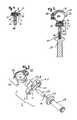
- Fig. 3shows the in Fig. 2 illustrated handle in an exploded view.
- the fastening device 22with the metallic open ring 24, the space defined by him 30, the tensioning device 28 and the lever member 26 shown.
- the damper 2which is already in Fig. 1 was shown, shown.
- the two-part shuttering 6which is composed of two shell parts 6.1 and 6.2, shown.
- Each of the shell parts 6.1, 6.2essentially forms a half-cylinder jacket which is capable of accommodating the cylindrical elastic element 4 and the plate-shaped bottoms of the connecting elements 8, 10.
- the two half-cylinder jacket-shaped shuttering parts 6.1, 6.2form the complete and substantially cylindrical casing 6, which is held together in the assembled state by the metal ring 16.
- the spacing device 12is likewise of cylindrical design, wherein the cylinder axis of the spacing device 12 is substantially aligned with the cylinder axis of the damping device 32.
- the diameter of the cylindrical spacing device 12is substantially smaller than the first diameter of the damping device 32.
- the grip device 18is screwed via the recess 14 and a screw 20.
- the rotationally symmetrical gripping device 18, with its axis of symmetry,likewise lies essentially on the cylinder axis of the spacing device 12 and the damping device 32.
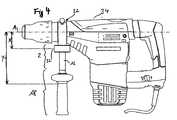
- Fig. 4shows a power tool 34 according to the invention with a handle according to the invention, the elements already shown and described in the previous figures having.
- the handlehas the damping device 32, the spacing device 12, the gripping device 18 and the fastening device 22.
- the fastening device 22is arranged on the power tool 34 such that a vibration axis A of the power tool 34 is enclosed by the fastening device 22.
- the vibration axis A of the power tool 34is formed in this example by an axis along which the power tool designed as a hammer drill 34 acts on a substrate.
- the axis Aextends centrally through the space 30 of the fastener 22nd
- Fig. 4shows here that a first distance Y between the vibration axis A of the power tool 34 and the grip device 18 is at least twice as large as a second distance X between the vibration axis A of the power tool 34 and the damping device 32 of the damper 2.
- the spacing device 12ensures that that the distance of the gripping device 18 from the damping device 32 is sufficiently large so that this ratio between the first distance Y and the second distance X is maintained.
- the first distance Yis measured from the vibration axis A to a point on the grip device, where the thumb and forefinger meet in the usual hand position.
- the damping member 32is mounted as close to the housing of the power tool 34 as possible.
- handle device 18provided as close as possible to power tool 34, a ratio according to the invention between the two distances Y and X can still be ensured.
- power tool 34may be a drill or impact drill instead of a hammer drill.
- other power tools with a vibration axis or with strong vibration or vibration, which arise in a defined direction or at a defined location,are basically suitable for the application of the damper according to the invention.
- the handlemay be connected by a clamping device 22 with the power tool 34 as in the present embodiment.
- the handleis firmly joined to the power tool.
- a fferbefest Trent the handle on the power tool 34is conceivable and the damper 2 of the invention can also be retrofitted as a spacer element between an existing already on a power tool handle and this handle, if the handle can be solved by the power tool.
- the assembly of the handledoes not necessarily have to be such that a fastener must be aligned in the region of a vibration axis and can be attached to many different locations of the power tool 34.
- the casing 6 of the damper 2is used in the embodiment described here not only as a stop but also as a tear-off. If the elastic element 4, which connects the two connecting elements 8, 10 via their bottom sections with each other, tear due to signs of aging or overload, the casing 6 securely holds the handle and the power tool together. A failure of the casing 6 is due to the metal ring 16 of the invention, which can also be made of a material other than metal, within the conceivable limits of use of the power tool limits almost impossible.
- the diameter of the cylindrical damping element 32need not be greater than the diameter of the spacer 12. It is also conceivable that such a damping device integral with the Spacing device and / or the handle device is executed. Also, the fastener may be integral with the damper and the handle device. Depending on the tool, spacers of different lengths may also be provided, which enables a particularly flexible and versatile application of the damper according to the invention in power tools.
Landscapes
- Engineering & Computer Science (AREA)
- Mechanical Engineering (AREA)
- Percussive Tools And Related Accessories (AREA)
Description
Translated fromGermanDie Erfindung bezieht sich auf einen Dämpfer zum Montieren zwischen einem Elektrowerkzeug mit einer Vibrationsachse einerseits und einer Griffeinrichtung für das Elektrowerkzeug andererseits, wobei der Dämpfer eine Dämpfungseinrichtung zum Dämpfen von Stößen und eine Beabstandungseinrichtung umfasst. Die Erfindung bezieht sich ferner auf einen Handgriff für ein Elektrowerkzeug mit einer Vibrationsachse und auf ein Elektrowerkzeug mit einer Vibrationsachse, insbesondere eine Bohr- oder Schlagbohrmaschine oder einen Bohrhammer.The invention relates to a damper for mounting between a power tool having a vibration axis on the one hand and a handle device for the power tool on the other hand, wherein the damper comprises a damping device for damping shocks and a spacing device. The invention further relates to a handle for a power tool having a vibration axis and to a power tool having a vibration axis, in particular a drilling or impact drill or a hammer drill.
Handgeführte Werkzeugmaschinen wie Elektrowerkzeuge, z.B. Winkel- bzw. Trennschleifer, Poliermaschinen, Bohrmaschinen, Bohrhämmer o. dgl. weisen einen Haupthandgriff auf, der an einem Motorgehäuse o. dgl. angeformt bzw. befestigt ist. Die Werkzeugmaschine wird am Haupthandgriff gefasst und geführt. In Ergänzung dazu kann es zweckmäßig sein, einen Zusatzhandgriff für die weitere Hand des Benutzers vorzusehen. Ein solcher Zusatzhandgriff ist üblicherweise lösbar beispielsweise am Getriebegehäuse der Werkzeugmaschine befestigt. Als Stielhandgriff ausgeführt steht er radial zur Längsachse der Werkzeugmaschine hervor und erleichtert die Führung bei schwierigen Bearbeitungsaufgaben.Hand-held machine tools such as power tools, e.g. Angle or cut-off grinder, polishing machines, drills, rotary hammers o. The like. Have a main handle, which is integrally formed or attached to a motor housing o. The machine tool is grasped and guided by the main handle. In addition, it may be appropriate to provide an additional handle for the other hand of the user. Such an additional handle is usually releasably attached, for example, on the gear housing of the machine tool. Run as a handle handle he stands out radially to the longitudinal axis of the machine tool and facilitates the leadership in difficult machining tasks.
Betriebsbedingt erzeugte Vibrationen pflanzen sich von der Werkzeugmaschine insbesondere durch den Zusatzhandgriff auf die Hand bzw. den Arm des Benutzers fort. Um das Vibrationsniveau, das auf den Benutzer einwirkt, zu verringern, werden vorbekannte Stiel- bzw. Zusatzhandgriffe mit elastischen Dämpfungselementen versehen. Ein Beispiel für einen aus dem Stand der Technik bekannten Zusatzhandgriff zur Verminderung des Vibrationsniveaus, das auf den Benutzer einwirkt, wird in der
Ein Dämpfer gemäss den Oberbegriff des Anspruchs 1 ist aus
Die Vibrationen des Elektrowerkzeuges, beispielsweise einer Bohr-, Schlagbohrmaschine oder eines Bohrhammers entstehen dabei entlang einer Vibrationsachse. Die Vibrationsachse bezeichnet zum Beispiel im Fall eines Bohrhammers die Achse, entlang der ein Meißelwerkzeug o. dgl. auf den zu bearbeitenden Untergrund aufgeschlagen wird. Die hier entstehenden Erschütterungen und Vibrationen werden einerseits direkt über das Werkzeuggehäuse und den daran angeformten Hauptangriff als auch via den Zusatzhandgriff auf die Hände bzw. die Arme des Benutzers übertragen. Aufgrund der teilweise enormen Erschütterungen und Vibrationen, die bei der Benutzung eines entsprechenden Elektrowerkzeugs entstehen, stellen diese hohe Belastungen, insbesondere auf die Gelenke des Benutzers dar. Eine Dämpfung dieser Vibrationen ist insbesondere im Sinne der Arbeitsmedizin unbedingt notwendig, um bleibende gesundheitliche Schäden, die aus der Benutzung eines solchen Elektrowerkzeuges resultieren können, nachhaltig zu verhindern.The vibrations of the power tool, such as a drill, percussion drill or hammer drill arise while along a vibration axis. For example, in the case of a hammer drill, the axis of vibration designates the axis along which a bit tool or the like is impacted onto the substrate to be worked. The resulting vibrations and vibrations are transmitted on the one hand directly on the tool housing and the molded main attack as well as via the auxiliary handle on the hands or the arms of the user. Due to the sometimes tremendous shocks and vibrations that occur when using a corresponding power tool, they represent high loads, especially on the joints of the user. A damping of these vibrations is especially in the interests of occupational medicine essential to permanent health damage from The use of such a power tool can result in sustainable prevent.
Die Dämpfungswirkung der aus dem Stand der Technik bekannten Dämpfungselemente ist jedoch noch nicht optimal. Es ist ein Griffteil und ein Dämpfungselement vorhanden, die mit einem Befestigungsteil mit der Werkzeugmaschine verbunden sind. Bei Zusatzhandgriffen im Stand der Technik ist die Anordnung des Dämpfungselementes dabei in verschiedenen Konfigurationen in einem Griffteil oder als Verbindung zwischen einem Griffteil und einem Befestigungsteil vorgesehen. Des Weiteren wird im Stand der Technik auch eine Abrisssicherung als im Allgemeinen notwendig anerkannt, damit bei einer Beschädigung des Dämpfungselementes ein Abreißen des Griffteils verhindert werden kann. Die im Stand der Technik beschriebenen Abrisssicherungen gestalten sich jedoch aufwändig und kostenintensiv.However, the damping effect of the known from the prior art damping elements is not optimal. There is a grip part and a damping element, which are connected to a fastening part with the machine tool. In additional handles in the prior art, the arrangement of the damping element is provided in various configurations in a handle part or as a connection between a handle part and a fastening part. Furthermore, in the prior art, a tear-off protection is generally recognized as necessary in order to prevent tearing of the handle part when the damping element is damaged. Those described in the prior art However, tears are expensive and expensive.
Insgesamt ist die Dämpfungswirkung der im Stand der Technik beschriebenen Zusatzhandgriff mit elastischen Dämpfungselementen nicht zufriedenstellend.Overall, the damping effect of the additional handle described in the prior art with elastic damping elements is not satisfactory.
Aufgabe der vorliegenden Erfindung ist es, einen dem oben genannten technischen Gebiet zugehörigen Dämpfer, einen Handgriff für ein Elektrowerkzeug und ein Elektrowerkzeug mit einem Handgriff zur Verfügung zu stellen, bei dem Vibrationen, die entlang einer Vibrationsachse entstehen, besonders gut gedämpft werden.The object of the present invention is to provide a damper, a handle for a power tool and a power tool with a handle that is associated with the abovementioned technical field, in which vibrations that occur along a vibration axis are particularly well damped.
Die Lösung der Aufgabe wird durch die Merkmale des Anspruchs 1 zur Verfügung gestellt. Erfindungsgemäß ist die Beabstandungseinrichtung derart bemessen, dass bei montiertem Dämpfer ein Verhältnis eines ersten Abstands zwischen der Vibrationsachse und der Griffeinrichtung zu einem zweiten Abstand zwischen der Vibrationsachse und der Dämpfungseinrichtung mindestens 2:1 beträgt. Mit anderen Worten ist also der Abstand zwischen der Vibrationsachse und der Griffeinrichtung mindestens doppelt so groß wie der Abstand zwischen der Vibrationsachse und der Dämpfungseinrichtung. Die Dämpfungseinrichtung ist zwischen der Griffeinrichtung und der Beabstandungseinrichtung angeordnet. Die Vibrationsachse stellt hierbei eine Achse dar, entlang welcher Vibrationen beim Betrieb eines Elektrowerkzeuges entstehen können. Ein Beispiel für eine solche Vibrationsachse ist die Achse, um die sich ein Bohrer einer Schlagbohrmaschine dreht, oder eine Schlagachse eines Bohrhammers. Da die Vibrationen, die entlang dieser Achse entstehen, besonders groß sind und allfällige Vibrationen des Elektromotors oder anderer Peripheriegeräte des Elektrowerkzeuges in ihrer Intensität weit überstrahlen, ist es von besonderer Bedeutung, eben diese starken Vibrationen bei ihrer Fortpflanzung auf eine Hand bzw. einen Arm eines Benutzers des Elektrowerkzeuges weitgehend zu dämpfen. Erfindungsgemäß wird also der Abstand zwischen der Griffeinrichtung und der Dämpfungseinrichtung so gewählt, dass die Dämpfungseinrichtung besonders effizient Vibrationen dämpft. Hierzu soll der Abstand der Griffeinrichtung zur Dämpfungseinrichtung möglichst groß im Verhältnis zum Abstand der Dämpfungseinrichtung zu dem Ort sein, an dem die zu dämpfenden Vibrationen entstehen, wobei eine komfortable Benutzung des Elektrowerkzeugs nicht außer Acht zu lassen ist. Die Beabstandungseinrichtung kann hierbei sowohl als separates Element als auch integral mit der Dämpfungseinrichtung und/oder der Griffeinrichtung vorgesehen sein.The solution of the problem is provided by the features of claim 1. According to the invention, the spacing device is dimensioned such that when the damper is mounted, a ratio of a first distance between the vibration axis and the grip device to a second distance between the vibration axis and the damping device is at least 2: 1. In other words, therefore, the distance between the vibration axis and the grip device is at least twice as large as the distance between the vibration axis and the damping device. The damping device is arranged between the grip device and the spacing device. The vibration axis here represents an axis along which vibrations during operation of a power tool can arise. An example of such a vibration axis is the axis about which a drill of a percussion drill rotates, or a striking axis of a hammer drill. Since the vibrations that occur along this axis, are particularly large and any vibrations of the electric motor or other peripherals of the power tool far outweigh the intensity is It is of particular importance to attenuate just these strong vibrations when they propagate on a hand or arm of a user of the power tool largely. According to the invention, therefore, the distance between the grip device and the damping device is selected such that the damping device dampens vibrations particularly efficiently. For this purpose, the distance of the handle device to the damping device should be as large as possible in relation to the distance of the damping device to the place where the vibrations to be damped arise, with a comfortable use of the power tool is not disregarded. The spacing device can in this case be provided both as a separate element and integrally with the damping device and / or the grip device.
Mit Vorteil weist die Dämpfungseinrichtung ein elastisches Element und kann bevorzugt ferner ein Anschlagselement aufweisen. Derartige Elemente sind deshalb von Vorteil, weil die Dämpfungseinrichtung während ihres Betriebs Ermüdungserscheinungen aufzeigen kann, die im Extremfall zur Zerstörung der Dämpfungseinrichtung und gegebenenfalls zum Abreißen der Griffeinrichtung führen. Das elastische Element der Dämpfungseinrichtung dient dabei der Dämpfung, indem es sich in Wechselwirkung mit der Vibration des Elektrowerkzeugs verformt und die Vibrationen damit nur abgeschwächt an die Griffeinrichtung weitergibt.Advantageously, the damping device has an elastic element and may preferably also have a stop element. Such elements are advantageous because the damping device can show fatigue during their operation, leading in extreme cases to the destruction of the damping device and possibly to tearing off the grip device. In this case, the elastic element of the damping device serves to damp by deforming in interaction with the vibration of the power tool and thus only transmits the vibrations to the grip device in a weakened manner.
Bevorzugt weist die Dämpfungseinrichtung, die beispielsweise zylinderförmig ausgeführt sein kann, eine insbesondere mehrstückige Verschalung auf, welche Verschalung bevorzugt eine ringförmige Ummantelung, bevorzugt einen Metallring aufweist. Eine derartige Verschalung eignet sich beispielsweise besonders gut dafür, als Anschlagelement für die Dämpfungseinrichtung zu dienen. Die Dämpfungseinrichtung, insbesondere die mit dem elastischen Element zusammenwirkenden Teile, können in einem Grundzustand, der keine Krafteinwirkung durch eine dynamische Verformung des elastischen Elements aufnehmen muss, an der Verschalung anliegen. Die Verschalung umschließt daher bevorzugt die mit dem elastischen Element zusammenwirkenden Teile, so dass diese bei einem Versagen des elastischen Elementes, beispielsweise bei einem Reißen oder Brechen des elastischen Elements, in der Verschalung festgehalten werden. Somit kann verhindert werden, dass sich das Griffelement von dem Elektrowerkzeug, in dem der Dämpfer montiert ist, unbeabsichtigt löst. Eine ringförmige Ummantelung der Verschalung dient dabei der zusätzlichen Stabilität, die durch einen Metallring in besonderem Maße zu Verfügung gestellt wird. Eine stabile Verschalung dient dabei nicht nur dem Schutz des elastischen Elementes, das in der Verschalung aufgenommen sein kann, sondern weist auch eine besonders hohe Festigkeit auf, die in einer Verwendung der Verschalung als Anschlagselement und Absicherung von besonderer Bedeutung sein kann.Preferably, the damping device, which may be cylindrical, for example, has a particular multi-piece casing, which casing preferably has an annular sheath, preferably a metal ring. Such a casing is for example particularly well suited to serve as a stop element for the damping device. The damping device, in particular the cooperating with the elastic member parts, in a ground state, the must absorb no force due to a dynamic deformation of the elastic element, abut the casing. The shuttering therefore preferably surrounds the parts cooperating with the elastic element, so that they are held in the casing in the event of a failure of the elastic element, for example when the elastic element breaks or breaks. Thus, the handle member can be prevented from being inadvertently released from the power tool in which the damper is mounted. An annular sheathing of the casing serves for additional stability, which is provided by a metal ring in particular. A stable casing not only serves to protect the elastic element, which can be accommodated in the casing, but also has a particularly high strength, which may be of particular importance in a use of the casing as a stop element and protection.
Mit Vorteil weist der Dämpfer ferner eine Befestigungseinrichtung zum Befestigen des Dämpfers an dem Elektrowerkzeug auf, die insbesondere mit einer Einspanneinrichtung versehen ist. Eine dämpferseitige Befestigungseinrichtung hat den Vorteil, dass der Dämpfer mit einer Vielzahl von Elektrowerkzeugen verwendet werden kann. Somit ist auch ein nachträgliches Ausrüsten eines Elektrowerkzeuges mit dem erfindungsgemäßen Dämpfer ohne Probleme möglich. In der vorteilhaften Ausgestaltung der Befestigungseinrichtung als Einspanneinrichtung ist darüber hinaus auch kein Gewinde oder ähnliches am Elektrowerkzeug nötig. Vielmehr kann der Dämpfer direkt an das Gehäuse des Elektrowerkzeuges angespannt werden und ist damit auch, beispielsweise zum Transport, besonders leicht wieder abzunehmen. Die Befestigungseinrichtung kann ansonsten beispielsweise durch ein Schraubgewinde gebildet werden, das in das Elektrowerkzeuggehäuse eingeschraubt werden kann.Advantageously, the damper further comprises a fastening device for fastening the damper to the power tool, which is provided in particular with a clamping device. A damper side fastener has the advantage that the damper can be used with a variety of power tools. Thus, a retrofitting of a power tool with the damper according to the invention without problems is possible. In the advantageous embodiment of the fastening device as a clamping device beyond no thread or the like on the power tool is necessary. Rather, the damper can be hooked directly to the housing of the power tool and is therefore also, for example, for transport, especially easy to remove again. The fastening device can otherwise be formed, for example, by a screw thread which can be screwed into the power tool housing.
Ein erfindungsgemäßer Handgriff für ein Elektrowerkzeug mit einer Vibrationsachse umfasst einen Dämpfer, der wie oben beschrieben ausgeführt sein kann, und eine mit dem Dämpfer verbundene Griffeinrichtung. Zusammen mit der Griffeinrichtung bildet der Dämpfer einen Handgriff für ein Elektrowerkzeug, mit dem ein Elektrowerkzeug geführt werden kann und der Vibrationen des Elektrowerkzeuges, die entlang einer Vibrationsachse entstehen, besonders gut dämpft. Mit Vorteil ist der Handgriff dadurch gekennzeichnet, dass die Dämpfungseinrichtung, die Beabstandungseinrichtung und die Griffeinrichtung, insbesondere in dieser Reihenfolge, linear aneinander anschließend angeordnet sind. Die Dämpfungseinrichtung, die Beabstandungseinrichtung und die Griffeinrichtung sind somit in einer Reihe aneinander anschließend angeordnet, so dass das Verhältnis zwischen den Abständen zwischen der Griffeinrichtung und der Vibrationsachse eines Elektrowerkzeuges, an das der Handgriff angebracht wird, und dem Abstand zwischen der Dämpfungseinrichtung und der Vibrationsachse besonders gut einstellbar. Die Dämpfungseinrichtung liegt somit zwischen der Griffeinrichtung und der Vibrationsachse und die Beabstandungseinrichtung liegt zwischen der Dämpfungseinrichtung und der Griffeinrichtung, wodurch der Abstand zwischen der Dämpfungseinrichtung und der Griffeinrichtung so eingestellt werden kann, dass das gewünschte Verhältnis der Abstände zwischen Griffeinrichtung und Vibrationsachse und Dämpfungseinrichtung und Vibrationsachse eingehalten werden kann.A handle according to the invention for a power tool with a vibration axis comprises a damper, which may be designed as described above, and a handle device connected to the damper. Together with the gripping device, the damper forms a handle for a power tool, with which a power tool can be guided and dampens the vibrations of the power tool, which arise along a vibration axis, particularly good. Advantageously, the handle is characterized in that the damping device, the spacing device and the gripping device, in particular in this order, are arranged linearly adjacent to one another. The damping device, the spacer device and the grip device are thus arranged adjacent to one another in a row, so that the ratio between the distances between the grip device and the vibration axis of a power tool, to which the handle is attached, and the distance between the damping device and the vibration axis is particularly easily adjustable. The damping device thus lies between the grip device and the vibration axis and the spacing device lies between the damping device and the grip device, whereby the distance between the damping device and the grip device can be adjusted so that the desired ratio of the distances between grip device and vibration axis and damping device and vibration axis complied can be.
Besonders bevorzugt sind die Dämpfungseinrichtung, die Beabstandungseinrichtung und die Griffeinrichtung jeweils durch Schraubbefestigungen miteinander verbunden. Auf diese Weise ist es besonders leicht möglich, auch einen vorhandenen Handgriff ohne eine erfindungsgemäße Dämpfungseinrichtung nachträglich mit einer solchen auszurüsten. Daneben ist es jedoch auch möglich, dass einzelne Elemente des Handgriffs einstückig miteinander ausgeführt sind. Dies gilt beispielsweise für die Beabstandungseinrichtung und die Griffeinrichtung sowie die Beabstandungseinrichtung und die Dämpfungseinrichtung. Die Dämpfungseinrichtung kann beispielsweise auch einstückig mit der Befestigungseinrichtung ausgeführt sein.Particularly preferably, the damping device, the spacing device and the gripping device are each connected to one another by screw fasteners. In this way, it is particularly easy to retrofit an existing handle without a damping device according to the invention with such a later. In addition, however, it is also possible that individual elements of the handle are made in one piece with each other. this applies for example, for the spacing device and the handle device and the spacing device and the damping device. The damping device may for example also be designed in one piece with the fastening device.
Ein erfindungsgemäßes Elektrowerkzeug mit einer Vibrationsachse, insbesondere eine Bohr- oder Schlagbohrmaschine oder ein Bohrhammer, ist dadurch gekennzeichnet, dass es einen oben beschriebenen Handgriff umfasst. Ein derartiges Elektrowerkzeug zeichnet sich durch eine besonders gute Vibrationsdämpfung der entlang der Vibrationsachse entstehenden Vibrationen aus. Das Elektrowerkzeug entspricht somit besonders hohen arbeitsmedizinischen Anforderungen und erlaubt auch eine ständige Verwendung des Elektrowerkzeuges, ohne dass gesundheitliche Schäden des Benutzers zu befürchten sind.A power tool according to the invention with a vibration axis, in particular a drilling or percussion drilling machine or a hammer drill, is characterized in that it comprises a handle described above. Such a power tool is characterized by a particularly good vibration damping of vibrations along the vibration axis. The power tool thus corresponds to particularly high occupational health requirements and also allows a constant use of the power tool, without any health damage to the user are to be feared.
Mit Vorteil ist das Elektrowerkzeug dadurch gekennzeichnet, dass ein erster Abstand der Griffeinrichtung des montierten Handgriffs zur Vibrationsachse größer ist als ein zweiter Abstand der Dämpfungseinrichtung des montierten Handgriffs zur Vibrationsachse, wobei ein Verhältnis vom ersten Abstand zum zweiten Abstand mindestens 2:1 beträgt. Ein Elektrowerkzeug, bei dem die Abstände zwischen der Vibrationsachse und der Griffeinrichtung und der Vibrationsachse und der Dämpfungseinrichtung so gewählt sind, dass der erste Abstand mindestens doppelt so groß ist wie der zweite Abstand, weist eine besonders gute Vibrationsdämpfung des montierten Handgriffs auf. Besonders bevorzugt ist der Handgriff dabei manuell, insbesondere durch einen Einspannmechanismus, abnehmbar. Ein solches Elektrowerkzeug zeichnet sich zusätzlich durch eine hohe Flexibilität aus, weil der Handgriff beispielweise zu Transportzwecken manuell abnehmbar ist. Manuell abnehmbar bedeutet in diesem Fall, dass kein zusätzliches Werkzeug benötigt wird, um den Handgriff von dem Elektrowerkzeug abzunehmen. Der oben beschriebene Einspannmechanismus stellt dabei eine besonders einfache Weise dar, den Handgriff manuell abnehmbar auszuführen. Daneben sind jedoch auch Schraubverbindungen oder ähnliche Befestigungsmethoden möglich.Advantageously, the power tool is characterized in that a first distance of the handle device of the mounted handle to the vibration axis is greater than a second distance of the damping device of the mounted handle to the vibration axis, wherein a ratio of the first distance to the second distance is at least 2: 1. A power tool, in which the distances between the vibration axis and the grip device and the vibration axis and the damping device are selected so that the first distance is at least twice as large as the second distance, has a particularly good vibration damping of the mounted handle. Particularly preferably, the handle is thereby manually, in particular by a clamping mechanism, removable. Such a power tool is also characterized by a high level of flexibility, because the handle, for example, for manual transport is removable. Manually detachable in this case means that no additional tool is needed to remove the handle from the power tool. The above described clamping mechanism is a particularly simple way to perform the handle manually removable. In addition, however, also screw or similar fastening methods are possible.
Aus der beiliegenden Figurenbeschreibung sowie der Gesamtheit der Ansprüche ergeben sich weitere vorteilhafte Ausgestaltungen der Erfindung.From the accompanying description of the figures and the entirety of the claims, further advantageous embodiments of the invention result.
- Fig. 1Fig. 1
- zeigt einen Dämpfer zum Montieren zwischen einem Elektrowerkzeug und einer Griffeinrichtung;shows a damper for mounting between a power tool and a handle device;
- Fig. 2Fig. 2
- zeigt einen Handgriff mit einem erfindungsgemäßen Dämpfer;shows a handle with a damper according to the invention;
- Fig. 3Fig. 3
- zeigt eine Explosionsdarstellung des Handgriffs aus
Fig. 2 ; undshows an exploded view of the handleFig. 2 ; and - Fig. 4Fig. 4
- zeigt ein Elektrowerkzeug mit einem Handgriff mit einem Dämpfer.shows a power tool with a handle with a damper.
An die obere und untere Stirnseite des zylindrischen elastischen Elements 4 ist jeweils eines der Verbindungselemente 8, 10 angebracht. An der oberen Stirnseite des elastischen Elementes 4 ist das erste Verbindungselement 8 angebracht, welches durch das elastische Element 4 mit einem Druck gegen die erste Stirnfläche der zylindrischen Verschalung 6 beaufschlagt wird. Das erste Verbindungselement 8 weist dabei einen tellerförmigen Boden auf, der eine dem elastischen Element 4 entsprechende Bodenfläche aufweist. Mit dem Boden ist einstückig eine Schraube ausgeführt, die einen zweiten Teil des Verbindungselementes 8 bildet. Die Schraube durchstößt dabei die erste Stirnseite der Verschalung 6 nach außen. Somit kann die Schraube des Verbindungselementes 8 an einer Befestigungseinrichtung mit einem entsprechenden Innengewinde befestigt werden, womit gleichfalls die Verschalung 6 und damit die darin befindlichen Elemente an der Befestigungseinrichtung befestigbar sind.At the upper and lower end side of the cylindrical
An der unteren Stirnseite des zylinderförmigen elastischen Elementes 4 befindet sich ein zweites Verbindungselement 10, das analog zum ersten Verbindungselement 8 ausgeführt ist, wobei ein schraubenförmiger Teil des zweiten Verbindungselementes 10, der ebenfalls einstückig mit einem tellerförmigen Boden ausgeformt ist, durch die untere Stirnseite der Verschalung 6 der Dämpfungseinrichtung 32 nach Außen stößt. Das elastische Element 4 ist dabei zwischen den Böden der beiden Verbindungselemente 8, 10 eingeklemmt, wodurch die Verbindungselemente 8, 10 mit einem Druck gegen die jeweils angrenzende obere und untere Stirnseite der im Wesentlichen zylinderförmigen Verschalung 6 gepresst werden.At the lower end side of the cylindrical
Aufgrund der Elastizität des elastischen Elementes 4 lässt sich jedoch eine Bewegung der Verbindungselemente 8, 10 sowohl in Richtung der Zylinderachse ins Innere der Verschalung 6, als auch eine Kippbewegung in Bezug auf diese Zylinderachse durchführen. Das elastische Element 4 federt eine solche Bewegung dabei ab.However, due to the elasticity of the
Die Verschalung 6 dient im Zusammenwirken mit den Bodenteilen der Verbindungselemente 8, 10 gleichzeitig als Anschlagelement für die Dämpfungseinrichtung 32. Die Verschalung 6 ist entlang ihres Zylindermantels durch einen Metallring 16 verstärkt. Der Metallring 16 ermöglicht dabei eine besonders große Festigkeit der Verschalung 6 gegenüber radialen Bewegungen der Verschalung. Insbesondere im Fall einer zweiteiligen Verschalung 6, die aus zwei Halbzylindern zusammengesetzt ist, ermöglicht der Metallring 16 auf einfache Weise eine sehr hohe Festigkeit der Verschalung 6.The
An dem zweiten Verbindungselement 10 ist in der in
Die Befestigungseinrichtung 22 weist dabei in ihrer dem Dämpfer 2 zugewandten Seite eine mit einem Innengewinde versehene Ausnehmung auf, die zur Befestigung des Dämpfers 2 mit der Befestigungseinrichtung 22 dient. Die Befestigungseinrichtung 22 weist dabei einen metallischen offenen Ring 24 auf, der einen im Wesentlichen kreisförmigen Raum 30 umschließt. Der Raum 30 dient dabei der Aufnahme eines Teils eines Elektrowerkzeuges 34, an welchem der Griff befestigt werden soll. Der metallische offene Ring 24 wird durch eine Spanneinrichtung 28 mit einem Spannhebel 26 zusammengehalten. Durch die Spanneinrichtung 28, die durch den Hebel 26 bedient wird, lässt sich der Umfang des offenen metallischen Rings 24 verjüngen. Auf diese Weise kann eine Spannung zwischen dem Handgriff und dem Elektrowerkzeug 34 erzeugt werden, so dass der Handgriff montagefrei lösbar mit dem Elektrowerkzeug 34 verbunden ist.The
An der Beabstandungseinrichtung 12 des Dämpfers 2 ist via die Ausnehmung 14 und ein schraubenförmiges Verbindungselement 20 eine Griffeinrichtung 18 befestigt. Die Beabstandungseinrichtung 12 sorgt dabei dafür, dass der Abstand zwischen der Griffeinrichtung 18 und dem elastischen Element 4 der Dämpfungseinrichtung 32 in einem ausreichend großen Verhältnis zum Abstand zwischen dem Mittelpunkt des Raums 30 des Befestigungselementes 22 und dem elastischen Element 4 liegt. Der Griff ist dabei bevorzugt aus einem Kunststoff gefertigt und mit einer federnden Schicht, insbesondere einer Gummischicht, überzogen, die einem Benutzer einen sicheren Halt ermöglicht und ein angenehmes Griffgefühl vermittelt.At the
Daran anschließend ist der Dämpfer 2, der schon in
An dem zweiten Verbindungselement 10 ist, wie schon in
An der Beabstandungseinrichtung 12 ist via die Ausnehmung 14 und eine Schraubverbindung 20 die Griffeinrichtung 18 angeschraubt. Die rotationssymmetrische Griffeinrichtung 18 liegt mit ihrer Symmetrieachse dabei ebenfalls im Wesentlichen auf der Zylinderachse der Beabstandungseinrichtung 12 und der Dämpfungseinrichtung 32.At the
Die Befestigungseinrichtung 22 ist dabei derart an dem Elektrowerkzeug 34 angeordnet, dass eine Vibrationsachse A des Elektrowerkzeuges 34 von der Befestigungseinrichtung 22 umschlossen wird. Die Vibrationsachse A des Elektrowerkzeugs 34 wird in diesem Beispiel durch eine Achse gebildet, entlang der das als Bohrhammer ausgeführte Elektrowerkzeug 34 auf einen Untergrund wirkt. Die Achse A verläuft zentral durch den Raum 30 des Befestigungselements 22.The
Das in
Der Handgriff kann wie im vorliegenden Ausführungsbeispiel durch eine Spanneinrichtung 22 mit dem Elektrowerkzeug 34 verbunden sein. Alternativ hierzu ist es jedoch auch möglich, dass der Handgriff fest an das Elektrowerkzeug gefügt ist. Auch eine Schraubbefestigung des Handgriffs an dem Elektrowerkzeug 34 ist denkbar und der erfindungsgemäße Dämpfer 2 kann auch als Beabstandungselement zwischen einem bereits an einem Elektrowerkzeug vorhandenen Handgriff und diesem Handgriff nachgerüstet werden, sofern sich der Handgriff vom Elektrowerkzeug lösen lässt. Die Montage des Handgriffs muss dabei nicht unbedingt derart erfolgen, dass ein Befestigungselement im Bereich einer Vibrationsachse ausgerichtet sein muss und kann an vielen verschiedenen Stellen des Elektrowerkzeuges 34 befestigt werden.The handle may be connected by a
Die Verschalung 6 des Dämpfers 2 dient in der hier beschriebenen Ausführungsform nicht nur als Anschlag sondern ebenfalls als Abrisssicherung. Sollte das elastische Element 4, das die beiden Verbindungselemente 8, 10 über deren Bodenabschnitte miteinander verbindet, aufgrund von Alterserscheinungen oder Überlastung reißen, so hält die Verschalung 6 den Handgriff und das Elektrowerkzeug sicher zusammen. Ein Versagen der Verschalung 6 ist auf Grund des erfindungsgemäßen Metallrings 16, der auch aus einem anderen Material als Metall hergestellt werden kann, innerhalb der bei einer Benutzung des Elektrowerkzeuges denkbaren Grenzen nahezu auszuschließen.The
Der Durchmesser des zylinderförmigen Dämpfungselementes 32 muss nicht größer sein als der Durchmesser der Beabstandungseinrichtung 12. Es ist auch denkbar, dass eine derartige Dämpfungseinrichtung integral mit der Beabstandungseinrichtung und/oder der Griffeinrichtung ausgeführt wird. Auch das Befestigungselement kann integral mit dem Dämpfer und der Griffeinrichtung ausgeführt sein. Je nach Werkzeug können auch verschieden lange Beabstandungseinrichtungen vorgesehen sein, die eine besonders flexible und vielseitige Anwendung des erfindungsgemäßen Dämpfers bei Elektrowerkzeugen ermöglicht.The diameter of the cylindrical damping element 32 need not be greater than the diameter of the
Claims (12)
- A shock absorber (2) for mounting between a power tool (34) having a vibration axis (A) on one side and a handle attachment (18) provided additionally to a main handle of the power tool (34) and extending at an angle to the vibration axis (A) for the power tool (34) on the other side, with a damping device (32) for damping vibration impacts,
wherein a spacer element (12) arranged between the handle attachment (18) and the damping device (32) is dimensioned such that the shock absorber (2) can be mounted so that a ratio of a first distance (Y) between the vibration axis (A) and the handle attachment (18) to a second distance (X) between the vibration axis (A) and the damping device (32) is at least 2:1,characterized in that the damping device (32) is configured for damping an axial motion along an axis and a tilting motion relative to the axis. - The shock absorber (2) as recited in claim 1,characterized in that the spacer element (12) is a separate component from the damping device (32) and the handle attachment (18) and is fitted between the damping device (32) and the handle attachment (18).
- The shock absorber (2) as recited in claim 1 or 2,characterized in that the damping device (32) has an elastic element (4).
- The shock absorber (2) as recited in any of claims 1 to 3,characterized in that the damping device (32) has a stop element (6).
- The shock absorber (2) as recited in any of claims 1 to 4,characterized in that the damping device (32) has a particularly multipart casing (6, 6.1, 6.2), which casing (6, 6.1, 6.2) preferably has an annular mantle (16), preferably a metal ring.
- The shock absorber (2) as recited in any of claims 1 to 5,characterized in that it also has a fastening means (22), particularly with a clamping means for fastening the shock absorber (2) to the power tool (34).
- An auxiliary handle for a power tool (34) with a vibration axis (A), comprising a shock absorber (2) as recited in any of claims 1 to 6 and a handle attachment (18) that is attached to the shock absorber (2).
- The auxiliary handle as recited in claim 7,characterized in that the damping device (32), the spacer element (12) and the handle attachment (18) are arranged and connected to each other linearly, particularly in this order.
- The auxiliary handle as recited in any of claims 1 to 8,characterized in that the damping device (32) the spacer element (12) and the handle attachment (18) are each attached to one another by screw fastenings (10, 20).
- A power tool (34) having a vibration axis (A), particularly a drill or percussion drill or a drill hammer,characterized in that it has an auxiliary handle as recited in any of claims 7 to 9.
- The power tool (34) as recited in claim 10,characterized in that a ratio of a first distance (Y) of the handle attachment (18) of the mounted auxiliary handle from the vibration axis (A) to a second distance (X) from the damping device (32) of the mounted handle to the vibration axis (A) is at least 2:1.
- The power tool (34) as recited in claim 10 or 11,characterized in that the auxiliary handle is detachable manually, particularly via a clamping device.
Priority Applications (3)
| Application Number | Priority Date | Filing Date | Title |
|---|---|---|---|
| EP08009186AEP2123406B1 (en) | 2008-05-19 | 2008-05-19 | Vibration dampened holder for additional hand grip |
| US12/467,898US8256528B2 (en) | 2008-05-19 | 2009-05-18 | Vibration-damped holder for additional handle |
| CN2009102034181ACN101585184B (en) | 2008-05-19 | 2009-05-19 | Vibration dampened holder for additional hand grip |
Applications Claiming Priority (1)
| Application Number | Priority Date | Filing Date | Title |
|---|---|---|---|
| EP08009186AEP2123406B1 (en) | 2008-05-19 | 2008-05-19 | Vibration dampened holder for additional hand grip |
Publications (2)
| Publication Number | Publication Date |
|---|---|
| EP2123406A1 EP2123406A1 (en) | 2009-11-25 |
| EP2123406B1true EP2123406B1 (en) | 2011-12-21 |
Family
ID=39639382
Family Applications (1)
| Application Number | Title | Priority Date | Filing Date |
|---|---|---|---|
| EP08009186AActiveEP2123406B1 (en) | 2008-05-19 | 2008-05-19 | Vibration dampened holder for additional hand grip |
Country Status (3)
| Country | Link |
|---|---|
| US (1) | US8256528B2 (en) |
| EP (1) | EP2123406B1 (en) |
| CN (1) | CN101585184B (en) |
Families Citing this family (31)
| Publication number | Priority date | Publication date | Assignee | Title |
|---|---|---|---|---|
| WO2007048435A1 (en)* | 2005-10-29 | 2007-05-03 | Aeg Electric Tools Gmbh | Portable power tool |
| JP5297392B2 (en)* | 2009-07-06 | 2013-09-25 | 株式会社マキタ | Thunder |
| DE202010002296U1 (en)* | 2010-02-11 | 2011-08-26 | Illinois Tool Works Inc. | Handle assembly |
| DE202010002297U1 (en)* | 2010-02-11 | 2011-06-09 | Illinois Tool Works, Inc., a Delaware Corp., Ill. | vibration |
| US9149923B2 (en) | 2010-11-09 | 2015-10-06 | Black & Decker Inc. | Oscillating tools and accessories |
| DE102011078376A1 (en)* | 2011-06-30 | 2013-01-03 | Robert Bosch Gmbh | Handle device, in particular for hand tools |
| US9278397B2 (en) | 2012-12-21 | 2016-03-08 | Jeremy Leman | Reciprocating saw with reinforced offset saw blade holder |
| DE102013201620A1 (en) | 2013-01-31 | 2014-08-14 | Hilti Aktiengesellschaft | Bendable holding device |
| JP5997660B2 (en)* | 2013-05-29 | 2016-09-28 | 株式会社マキタ | Auxiliary handle and reciprocating work tool with auxiliary handle |
| CN203542563U (en)* | 2013-10-23 | 2014-04-16 | 南京德朔实业有限公司 | Secondary handle and electric tool adopting same |
| US10272559B2 (en)* | 2014-11-12 | 2019-04-30 | Black & Decker Inc. | Side handle |
| EP3127658A1 (en)* | 2015-08-06 | 2017-02-08 | HILTI Aktiengesellschaft | Side grip |
| EP3127657A1 (en)* | 2015-08-06 | 2017-02-08 | HILTI Aktiengesellschaft | Side grip |
| US10442073B2 (en)* | 2015-10-16 | 2019-10-15 | Kenneth J. Brauer | Rotating handle and related methods |
| US11325235B2 (en)* | 2016-06-28 | 2022-05-10 | Black & Decker, Inc. | Push-on support member for fastening tools |
| US11267114B2 (en) | 2016-06-29 | 2022-03-08 | Black & Decker, Inc. | Single-motion magazine retention for fastening tools |
| US10987790B2 (en) | 2016-06-30 | 2021-04-27 | Black & Decker Inc. | Cordless concrete nailer with improved power take-off mechanism |
| US11279013B2 (en) | 2016-06-30 | 2022-03-22 | Black & Decker, Inc. | Driver rebound plate for a fastening tool |
| US11400572B2 (en) | 2016-06-30 | 2022-08-02 | Black & Decker, Inc. | Dry-fire bypass for a fastening tool |
| US10926385B2 (en) | 2017-02-24 | 2021-02-23 | Black & Decker, Inc. | Contact trip having magnetic filter |
| EP3597370A1 (en)* | 2018-07-17 | 2020-01-22 | Hilti Aktiengesellschaft | Handle and handheld machine tool |
| USD964134S1 (en) | 2018-09-07 | 2022-09-20 | Jeremy Leman | Reciprocating saw |
| US11433524B2 (en)* | 2018-12-19 | 2022-09-06 | George E. Westinghouse | Vibration reducing extension system |
| MX2021014887A (en) | 2019-06-12 | 2022-01-18 | Milwaukee Electric Tool Corp | Rotary power tool. |
| EP3756833A1 (en)* | 2019-06-26 | 2020-12-30 | Hilti Aktiengesellschaft | Side handle for an electric hand tool |
| DE202019105847U1 (en)* | 2019-10-21 | 2021-01-22 | C. & E. Fein Gmbh | Suction device |
| US11607795B2 (en)* | 2019-12-13 | 2023-03-21 | Kenneth J. Brauer | Rotating handle and related methods |
| US11691194B2 (en)* | 2020-05-04 | 2023-07-04 | The Boeing Company | Ergonomic riveting tool system |
| DE102020115087A1 (en)* | 2020-06-05 | 2021-12-09 | Festool Gmbh | Handle device for a hand machine tool |
| US12434369B2 (en) | 2021-05-14 | 2025-10-07 | Techtronic Cordless Gp | Handle for use with a power tool |
| JP2023090449A (en)* | 2021-12-17 | 2023-06-29 | 株式会社マキタ | power tools |
Family Cites Families (26)
| Publication number | Priority date | Publication date | Assignee | Title |
|---|---|---|---|---|
| DE2743043C2 (en)* | 1977-09-24 | 1987-05-14 | Fa. Andreas Stihl, 7050 Waiblingen | Vibration-damping connection between a vibration-exposed device part and a handle-side device part for a portable work tool |
| DE3580380D1 (en)* | 1984-03-30 | 1990-12-13 | Makoto Minamidate | VIBRATION DAMPING HANDLE. |
| SE442963B (en)* | 1984-05-07 | 1986-02-10 | Atlas Copco Ab | VIBRATION-INSULATING HANDLE |
| DE8701722U1 (en)* | 1987-02-05 | 1987-04-09 | Weber Maschinentechnik Gmbh, 5928 Laasphe | Handle for vibrating devices |
| US4825548A (en)* | 1987-03-31 | 1989-05-02 | White Consolidated Industries, Inc. | Vibration-damping control handle for a portable power tool |
| US4819742A (en)* | 1987-06-12 | 1989-04-11 | White Consolidated Industries, Inc. | Vibration-damping control handle for a portable power tool |
| DE3839207A1 (en)* | 1988-11-19 | 1990-05-23 | Hilti Ag | PORTABLE HAND DEVICE WITH STRIKE |
| DE4011124A1 (en)* | 1990-04-06 | 1991-10-10 | Metabowerke Kg | VIBRATION DAMPED HANDLE |
| SE467690B (en)* | 1990-12-11 | 1992-08-31 | Atlas Copco Tools Ab | VIBRATION INSULATED TOOL HANDLE |
| US5409560A (en)* | 1994-03-03 | 1995-04-25 | Hammer; Erik D. | Method of making liners for tool boxes |
| FR2726216B1 (en)* | 1994-10-29 | 1997-06-06 | Stihl Maschf Andreas | MANUALLY GUIDED MACHINE TOOL, ESPECIALLY BRUSH CUTTER OR TRIMMER |
| DE69616059T2 (en)* | 1995-07-13 | 2002-06-27 | Atlas Copco Berema Ab, Nacka | HANDLE FOR HANDWRITING MACHINES |
| US5797488A (en)* | 1996-08-21 | 1998-08-25 | Zag Ltd. | Case for a circular saw |
| DE19745306C2 (en)* | 1997-10-14 | 1999-09-09 | Fein C & E | Handle arrangement for an angle grinder |
| WO2000047862A1 (en)* | 1999-02-10 | 2000-08-17 | Anglo Operations Limited | Rock drill handle |
| DE19925281B4 (en)* | 1999-06-02 | 2014-10-02 | Andreas Stihl Ag & Co. | Hand-held implement, in particular hedge trimmer with vibration-damped handles |
| DE19943629B4 (en)* | 1999-09-11 | 2015-04-09 | Andreas Stihl Ag & Co. | Hand-held implement |
| US6209723B1 (en)* | 2000-01-25 | 2001-04-03 | Darren Fields | Tool wraps |
| DE10005080C1 (en)* | 2000-02-04 | 2001-08-02 | Bosch Gmbh Robert | Hand tool has handle with handle part fixed to casing by elastic, vibration-damping element and fixing part fixed at elastic element |
| DE10130548B4 (en)* | 2001-06-25 | 2008-01-03 | Robert Bosch Gmbh | Additional handle |
| DE10347944B4 (en)* | 2003-10-15 | 2016-11-10 | Robert Bosch Gmbh | Additional handle |
| DE102005007547B4 (en)* | 2005-02-18 | 2024-11-07 | Robert Bosch Gmbh | hand tool machine |
| DE102005059180A1 (en)* | 2005-12-12 | 2007-06-14 | Robert Bosch Gmbh | Hand tool with a drive train and a decoupling unit |
| EP1867443B1 (en) | 2006-06-14 | 2009-07-15 | AEG Electric Tools GmbH | Auxiliary handle for a manually operated machine tool |
| JP5029878B2 (en)* | 2007-01-31 | 2012-09-19 | 日立工機株式会社 | Electric tool |
| DE102007047083A1 (en) | 2007-10-01 | 2009-04-02 | Robert Bosch Gmbh | Additional handle |
- 2008
- 2008-05-19EPEP08009186Apatent/EP2123406B1/enactiveActive
- 2009
- 2009-05-18USUS12/467,898patent/US8256528B2/enactiveActive
- 2009-05-19CNCN2009102034181Apatent/CN101585184B/ennot_activeExpired - Fee Related
Also Published As
| Publication number | Publication date |
|---|---|
| US20090283283A1 (en) | 2009-11-19 |
| EP2123406A1 (en) | 2009-11-25 |
| US8256528B2 (en) | 2012-09-04 |
| CN101585184A (en) | 2009-11-25 |
| CN101585184B (en) | 2013-01-02 |
Similar Documents
| Publication | Publication Date | Title |
|---|---|---|
| EP2123406B1 (en) | Vibration dampened holder for additional hand grip | |
| DE19525251C2 (en) | Elastic compressible vibration isolation element for a vibrating tool | |
| DE102007012312A1 (en) | handle | |
| WO2009109247A1 (en) | Auxiliary handle and hand-held power tool | |
| DE102007055735A1 (en) | handle | |
| DE102007009169A1 (en) | Handle for handheld machine tool e.g. drilling machine, has handle sleeve arranged on handle core with vibration-isolating unit e.g. knitted fabric, fastening element, and vibration-isolating unit is pre-tensioned and made of metal | |
| DE2804223A1 (en) | Additional handle for motor driven drill - has internal flexible spacer sleeves, for isolating vibrations, which fit in longitudinal cut=out portion | |
| DE102006061247A1 (en) | handle | |
| DE102011000710A1 (en) | Torque transmission device in the form of a bit lining | |
| DE102007000408A1 (en) | Hand tool | |
| DE202017101409U1 (en) | Auxiliary handle and working tool | |
| EP3331665A1 (en) | Side handle | |
| EP2251151B1 (en) | Handheld power tool, in particular electric hand tool | |
| EP1674216B1 (en) | Lateral handgrip | |
| DE102007062714A1 (en) | handle | |
| EP2159009A1 (en) | Adapter for additional handheld grip and handheld grip | |
| DE19748987B4 (en) | Drilling tool, in particular for rotary impact drilling of preferably rock | |
| EP3213879A1 (en) | Vibration reducing auxiliary handle | |
| WO2009074410A1 (en) | Handle | |
| EP3341158A1 (en) | Setting tool | |
| DE19901047B4 (en) | Rod-shaped caulking tool | |
| WO2009047060A1 (en) | Auxiliary handle | |
| EP2237927A1 (en) | Auxiliary handle device | |
| EP4378629A1 (en) | Tool holding device for a rotary hammer or chisel hammer with an idle impact and bounce shock damping | |
| EP3996878B1 (en) | Sealing lip for tool holder |
Legal Events
| Date | Code | Title | Description |
|---|---|---|---|
| PUAI | Public reference made under article 153(3) epc to a published international application that has entered the european phase | Free format text:ORIGINAL CODE: 0009012 | |
| AK | Designated contracting states | Kind code of ref document:A1 Designated state(s):AT BE BG CH CY CZ DE DK EE ES FI FR GB GR HR HU IE IS IT LI LT LU LV MC MT NL NO PL PT RO SE SI SK TR | |
| AX | Request for extension of the european patent | Extension state:AL BA MK RS | |
| 17P | Request for examination filed | Effective date:20100521 | |
| AKX | Designation fees paid | Designated state(s):DE FR GB IT | |
| 17Q | First examination report despatched | Effective date:20101015 | |
| GRAP | Despatch of communication of intention to grant a patent | Free format text:ORIGINAL CODE: EPIDOSNIGR1 | |
| GRAS | Grant fee paid | Free format text:ORIGINAL CODE: EPIDOSNIGR3 | |
| GRAA | (expected) grant | Free format text:ORIGINAL CODE: 0009210 | |
| AK | Designated contracting states | Kind code of ref document:B1 Designated state(s):DE FR GB IT | |
| REG | Reference to a national code | Ref country code:GB Ref legal event code:FG4D Free format text:NOT ENGLISH | |
| REG | Reference to a national code | Ref country code:DE Ref legal event code:R096 Ref document number:502008005899 Country of ref document:DE Effective date:20120223 | |
| PLBE | No opposition filed within time limit | Free format text:ORIGINAL CODE: 0009261 | |
| STAA | Information on the status of an ep patent application or granted ep patent | Free format text:STATUS: NO OPPOSITION FILED WITHIN TIME LIMIT | |
| 26N | No opposition filed | Effective date:20120924 | |
| REG | Reference to a national code | Ref country code:DE Ref legal event code:R097 Ref document number:502008005899 Country of ref document:DE Effective date:20120924 | |
| REG | Reference to a national code | Ref country code:FR Ref legal event code:PLFP Year of fee payment:9 | |
| PGFP | Annual fee paid to national office [announced via postgrant information from national office to epo] | Ref country code:IT Payment date:20160531 Year of fee payment:9 | |
| REG | Reference to a national code | Ref country code:FR Ref legal event code:PLFP Year of fee payment:10 | |
| REG | Reference to a national code | Ref country code:FR Ref legal event code:PLFP Year of fee payment:11 | |
| PG25 | Lapsed in a contracting state [announced via postgrant information from national office to epo] | Ref country code:IT Free format text:LAPSE BECAUSE OF NON-PAYMENT OF DUE FEES Effective date:20170519 | |
| PGFP | Annual fee paid to national office [announced via postgrant information from national office to epo] | Ref country code:NL Payment date:20190612 Year of fee payment:16 | |
| REG | Reference to a national code | Ref country code:DE Ref legal event code:R119 Ref document number:502008005899 Country of ref document:DE | |
| PG25 | Lapsed in a contracting state [announced via postgrant information from national office to epo] | Ref country code:DE Free format text:LAPSE BECAUSE OF NON-PAYMENT OF DUE FEES Effective date:20201201 | |
| PGFP | Annual fee paid to national office [announced via postgrant information from national office to epo] | Ref country code:GB Payment date:20220526 Year of fee payment:15 | |
| P01 | Opt-out of the competence of the unified patent court (upc) registered | Effective date:20230612 | |
| GBPC | Gb: european patent ceased through non-payment of renewal fee | Effective date:20230519 | |
| PG25 | Lapsed in a contracting state [announced via postgrant information from national office to epo] | Ref country code:GB Free format text:LAPSE BECAUSE OF NON-PAYMENT OF DUE FEES Effective date:20230519 | |
| PGFP | Annual fee paid to national office [announced via postgrant information from national office to epo] | Ref country code:FR Payment date:20250526 Year of fee payment:18 |