EP2123225B1 - Endoscope device - Google Patents
Endoscope deviceDownload PDFInfo
- Publication number
- EP2123225B1 EP2123225B1EP09006717.4AEP09006717AEP2123225B1EP 2123225 B1EP2123225 B1EP 2123225B1EP 09006717 AEP09006717 AEP 09006717AEP 2123225 B1EP2123225 B1EP 2123225B1
- Authority
- EP
- European Patent Office
- Prior art keywords
- main body
- distal end
- observation
- insertion part
- end portion
- Prior art date
- Legal status (The legal status is an assumption and is not a legal conclusion. Google has not performed a legal analysis and makes no representation as to the accuracy of the status listed.)
- Not-in-force
Links
Images


Classifications
- A—HUMAN NECESSITIES
- A61—MEDICAL OR VETERINARY SCIENCE; HYGIENE
- A61B—DIAGNOSIS; SURGERY; IDENTIFICATION
- A61B17/00—Surgical instruments, devices or methods
- A61B17/00234—Surgical instruments, devices or methods for minimally invasive surgery
- A—HUMAN NECESSITIES
- A61—MEDICAL OR VETERINARY SCIENCE; HYGIENE
- A61B—DIAGNOSIS; SURGERY; IDENTIFICATION
- A61B1/00—Instruments for performing medical examinations of the interior of cavities or tubes of the body by visual or photographical inspection, e.g. endoscopes; Illuminating arrangements therefor
- A61B1/00064—Constructional details of the endoscope body
- A61B1/00071—Insertion part of the endoscope body
- A61B1/0008—Insertion part of the endoscope body characterised by distal tip features
- A61B1/00087—Tools
- A—HUMAN NECESSITIES
- A61—MEDICAL OR VETERINARY SCIENCE; HYGIENE
- A61B—DIAGNOSIS; SURGERY; IDENTIFICATION
- A61B1/00—Instruments for performing medical examinations of the interior of cavities or tubes of the body by visual or photographical inspection, e.g. endoscopes; Illuminating arrangements therefor
- A61B1/012—Instruments for performing medical examinations of the interior of cavities or tubes of the body by visual or photographical inspection, e.g. endoscopes; Illuminating arrangements therefor characterised by internal passages or accessories therefor
- A61B1/018—Instruments for performing medical examinations of the interior of cavities or tubes of the body by visual or photographical inspection, e.g. endoscopes; Illuminating arrangements therefor characterised by internal passages or accessories therefor for receiving instruments
Definitions
- the present inventionrelates to an endoscope device which is inserted into the body cavity and is used together with a device such as a flexible endoscope.
- endoscope devicesare used for observing and treating an affected area or the like within the body cavity of the subject.
- Endoscope devicesare known in which an elongated and flexible insertion part which is inserted into the body cavity from the distal side, and an operating part for operating the insertion part are provided so as to connect to each other.
- the distal portion of the insertion partis provided with an observation main body for observing the periphery, and a distal end construction part on the distal end surface of which two arm members into which treatment tools for performing treatment are inserted are provided.
- a bendable tubular bending partis connected to the proximal side of the distal end portion, and a flexible tubular part which is connected with an operating part is connected to the proximal side of the bending part.
- a distal portion of an operating wire inserted into the bending part and the flexible tuber partis fixed to the proximal side of the distal end construction part, and the proximal portion of the operating wire is attached to an angle knob which is provided in the operating part and pulls the operating wire.
- Instrument channelsare formed so as to extend from the distal portions of the two arm members to a forceps plug provided in the operating part via the insertion part. By inserting the treatment tools into the instrument channels, treatment can be performed with the distal portions of the treatment tools protruded from the distal ends of the arm members.
- the insertion partis inserted into the body cavity of the subject while observing the periphery by using the observation main body and bending the bending part by using the angle knob so that the distal portions of the treatment tools do not protrude from the distal ends of the two arm members. Then, the insertion part is fixed so that the two arm members are opposed to the affected area and the distal end portions of the treatment tools are protruded from the distal ends of the arm members to perform treatment.
- US 2005/0272977 A1relates to an apparatus for obtaining endoluminal access.
- An elongate bodyis configured for insertion within a body lumen, conduit, organ, orifice, passageway or cavity, the elongate body having a working axis and a distal region, and an articulating element disposed near the distal region, the articulating element configured to articulate off-axis from the working axis of the elongate body.
- the two part form of appended claim 1is based on this disclosure.
- the present inventionwas devised in view of the above circumstances, and has as an object the provision of an endoscope device in which depression of the insertion ability of the insertion part is prevented and visibility of the distal portions of the arm members when performing treatment is enhanced.
- the present inventionrelates to an endoscope device as set out in appended claim 1.
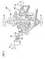
- an endoscope device 1has an operating part 2 and a tubular insertion part 3 which extends from one end of the operating part 2 in a unitary manner.
- the insertion part 3is elongated and has flexibility.
- the insertion part 3has the same construction as an insertion part described in U.S. Patent Application No. 11/435,183 or U.S. Patent Application No. 11/652,880 . That is, the insertion part 3 has a sheath 4, a distal end portion 7 which is disposed in the distal portion of the sheath 4, and bendable first and second arm members 5A and 5B which are provided on a distal end surface 7h of the distal end portion 7 so as to protrude forward.
- Instrument channels 6are formed inside the arm members 5A and 5B .respectively, and extend to connect with a later-described connection sheath 20 via the insertion part 3 and operating part. 2.
- Treatment tools 8A and 8Bare inserted into the instrument channels 6 respectively, and treatment parts 9A and 9B of the treatment tools 8A and 8B protrude from the distal portions of the arm members 5A and 5B respectively. According to these treatment tools 8A and 8B, the first and second arm members 5A and 5B can perform treatment within the body cavity.
- a first bending part 11 and a second bending part 12are formed in each arm member 5A and 5B in order from the distal side. Bending operation within the body cavity can be performed by moving the first and second bending parts 11 and 12 together with a third bending part 13 formed in the insertion part 3.
- An observation main body 14 for observing inside the bodyis disposed on the outer circumferential surface of the distal portion of the distal end construction part 7 so as to be capable of separating from the insertion part 3.
- the observation main body 14is held by a holding mechanism 15.
- the first and second arm members 5A and 5Bmay be inserted into another sheath protruding from the distal end of the sheath 4, as described in U.S. Patent Application No. 11/652,880 .
- a forceps plug 16is provided in the operating part 2 at the side surface of the one end portion connecting to the insertion part 3.
- the forceps plug 16communicates with the instrument channels 6 formed within the sheath 4.
- a second treatment tool(not shown) from the forceps plug 16
- the second treatment toolcan be protruded from the distal end of first or second arm member 5A or 5B.
- the operating part 2is further provided with a switch 17, an angle knob 18, and a universal cable 19 which is connected to a control device or a monitor (not shown).
- the switch 17is operated, for example, when feeding air or water, or aspirating through the instrument channel 6 formed within the insertion part 3.
- the angle knob 18is used when bending the third bending part 13 in all directions with respect to the axis. An image observed by the observation main body 14 is transmitted to the monitor via the universal cable 19.
- the elongated and flexible connecting sheath 20is provided so as to extend from the other end portion of the operating part 2.
- An operator 25is provided at the end portion of the connection sheath 20.
- the operator 25has a base 26 which fixes the connection sheath 20.
- a first operating unit 30A and a second operating unit 30Bare attached with respect to the base 26.
- the first operating unit 30Ahas an operating stick 31A into which an operating part 10A of the treatment tool 8A inserted into the first arm member 5A is inserted.
- the operating part 10Ais supported via the operating stick 31 A so as to freely advance and retract in the axial direction and to freely lean in all directions about the axis.
- the second operating unit 30Bhas an operating stick 31B into which an operating part 10B of the treatment tool 8B inserted into the first arm member 5B is inserted.
- the operating part 10Bis supported via the operating stick 31B so as to freely advance and retract in the axial direction and to freely lean in all directions about the axis.
- the first rotation mechanism 32Arotates to the direction E1.
- the first bending part 11 of the first arm member 5Ais bent to the direction F1 as shown in FIG. 1 by an operating wire (not shown) wound on the first rotation mechanism 32A.
- the second rotation mechanism 33Arotates to the direction E2.
- the first bending part 11 of the first arm member 5Ais bent to the direction F2 orthogonal to the direction F1 (i.e., the direction orthogonal to the sheet) by an operating wire (not shown) wound on the second rotation mechanism 33A.
- the first bending part 11 of the second arm member 5Bis similarly bent when an operating stick 31B shown in FIG 2 is rotated.
- a gripping forcepsis employed as the treatment tool 8A and an injection instrument is employed as the treatment tool 8B.
- the opening/closing operation of the distal portion of this gripping forcepsis performed by moving a slider 35A with respect to a ring 34A in the axial direction to pull and push an operating wire (not shown) connected to the treatment part 9A.
- an operating wirenot shown
- a slider 35 provided in the second operating unit 30 Bis operated.
- a gripping forceps and an injection instrumentare employed as the treatment tools 8A and 8B, this invention is not limited thereto and, for example, other treatment tools such as a high-frequency treatment tool, scissors, or a high-frequency snare may be employed.
- a first groove 7ais formed along the axis C1 of the insertion part 3 on the outer circumferential surface of the distal end portion 7, and the observation main body 14 is disposed within the first groove 7a.
- the observation main body 14houses a light receiving element such as a lens and a CCD, and connects to an observation cable 43 which transmits an image obtained by the observation main body 14 to the monitor.
- the observation cable 43has a bending tendency and plays a role as an biasing member which biases the observation main body 14 disposed in the first groove 7a toward the moving direction G1 opposite to the first and second arm members 5A and 5B in the radial direction of the insertion part 3.
- the observation cable 43is guided by a guide hole (not shown) communicating from the distal end construction part 7 of the insertion part 3 to the operating part 2.
- the opposite side of the first and second arm members 5A and 5B in the radial direction of the insertion part 3means a symmetrical side with the midpoint P between the positions where the first and second arm members 5A and 5B are provided on the distal end surface 7h of the distal end portion 7, with respect to the axis C1.
- a second groove 7bis formed along the circumferential direction on the outer circumferential surface of the distal end portion 7, and a curved plate-shaped open/close member 41 is supported by the second groove 7b so as to freely move along the circumferential direction of the distal end construction part 7.
- the open/close member 41is set such that, when moving to one side of the second groove 7b, the open/close member 41 resists the biasing force by the observation cable 43 to hold the observation main body 14 in a state where the observation main body 14 is disposed within the first groove 7a, and, when moving from the position shown in FIG 4 to the other side of the second groove 7b, the holding state of the observation main body 14 is released.
- Both end portions of the open/close member 41are connected to an open/close member driving wire 44.
- the open/close member driving wire 44is guided by the guide hole (not shown) communicating from the distal end construction part 7 of the insertion part 3 to the operating part 2, and is operated by an observation main body operating lever (not shown) provided in the operating part 2.
- the open/close member 41 and the open/close member driving wire 44constitute the above-described holding mechanism 15.
- the operating leveris pushed such that the first and second arm members 5A and 5B are parallel to each other.
- the treatment tools 8A and 8Bare pulled with respect to the operating parts 10A and 10B to make the treatment parts 9A and 9B be in a state where the treatment parts 9A and 9B do not protrude from the distal ends of the arm members 5A and 5B.
- the peripheryis observed by the observation main body 14, and the insertion part 3 is inserted into the body cavity of the subject while bending the first bending portions 11 of the arm members 5A and 5B by using the first and second operating units 30A and 30B respectively and bending the third bending part 13 by using the angle knob 18.
- the insertion part 3is fixed in a state where the distal portions of the two arm members 5A and 5B are opposed to the affected area.
- the treatment tools 8A and 8Bare pushed with respect to the operating parts 10A and 10B such that the treatment parts 9A and 9B of the treatment tools 8A and 8B are protruded from the distal ends of the arm members 5A and 5B as shown in FIG. 4 .
- the second bending parts 12are fixed in a bending state where the first and second arm members 5A and 5B are separated from each other.
- the open/close member 41is moved to the other side of the second groove 7b to release the holding state of the observation main body 14.
- the observation cable 43biases the observation main body 14 disposed in the first groove 7a toward the moving direction G1
- the observation main body 14is moved to a position separating from the distal end portion 7 while maintaining the posture of the observation main body 14.
- the affected areais grasped by the treatment part 9A by rotating the operating stick 31A to bend the first bending part 11 of the first arm member 5A and by moving the slider 35A. Then, the needle-shaped treatment part 9B is pricked into the affected area while bending the first bending part 11 of the second arm member 5B by rotating the operating stick 31B, and the drug solution or the like (not shown) is injected into the affected area by moving the slider 35B.
- the operating leveris pushed such that the first and second arm members 5A and 5B are parallel to each other.
- the treatment tools 8A and 8Bare pulled with respect to the operating parts 10A and 10B to make the treatment parts 9A and 9B in a state where the treatment parts 9A and 9B do not protrude from the distal ends of the arm members 5A and 5B.
- the observation main body 14is housed within the sheath 4 by pulling the observation cable 43 toward the proximal end. After making the insertion part 3 in this state, the insertion part 3 is pulled toward the proximal end so as to be pulled out from the body cavity.
- the first and second arm members 5A and 5Bare provided on the distal end surface 7h of the distal end portion 7, and the observation main body 14 is disposed within the first groove 7a. Therefore, since the outer diameter of the insertion part 3 including the arm members 5A and 5B can be reduced, the depression of the insertion ability of the insertion part 3 when inserting the insertion part 3 into the body cavity of the subject can be prevented.
- the treatment parts 9A and 9Bcan be observed from the skew direction, not from the proximal side of the first and second arm members 5A and 5B.
- the observation main body 14since it can be prevented that the field of view via the observation main body 14 is interrupted by the proximal portions of the first and second arm members 5A and 5B when performing treatment, visibility of the treatment parts 9A and 9B can be improved.
- the distance from the treatment parts 9A and 9B to the observation main body 14can be elongated, the range of view of the treatment parts 9A and 9B via the observation main body 14 can be enlarged. As a result, the treatment of the affected area can be safely performed in brief time.
- first and second arm members 5A and 5Bare provided in the distal end surface 7h of the distal end construction part 7 in the described embodiment, three or more arm members may be provided.
Landscapes
- Health & Medical Sciences (AREA)
- Life Sciences & Earth Sciences (AREA)
- Surgery (AREA)
- General Health & Medical Sciences (AREA)
- Public Health (AREA)
- Veterinary Medicine (AREA)
- Nuclear Medicine, Radiotherapy & Molecular Imaging (AREA)
- Animal Behavior & Ethology (AREA)
- Molecular Biology (AREA)
- Engineering & Computer Science (AREA)
- Biomedical Technology (AREA)
- Heart & Thoracic Surgery (AREA)
- Medical Informatics (AREA)
- Biophysics (AREA)
- Radiology & Medical Imaging (AREA)
- Physics & Mathematics (AREA)
- Pathology (AREA)
- Optics & Photonics (AREA)
- Endoscopes (AREA)
- Instruments For Viewing The Inside Of Hollow Bodies (AREA)
Description
- The present invention relates to an endoscope device which is inserted into the body cavity and is used together with a device such as a flexible endoscope.
- Conventionally, endoscope devices are used for observing and treating an affected area or the like within the body cavity of the subject. Endoscope devices are known in which an elongated and flexible insertion part which is inserted into the body cavity from the distal side, and an operating part for operating the insertion part are provided so as to connect to each other.
- The distal portion of the insertion part is provided with an observation main body for observing the periphery, and a distal end construction part on the distal end surface of which two arm members into which treatment tools for performing treatment are inserted are provided. A bendable tubular bending part is connected to the proximal side of the distal end portion, and a flexible tubular part which is connected with an operating part is connected to the proximal side of the bending part. A distal portion of an operating wire inserted into the bending part and the flexible tuber part is fixed to the proximal side of the distal end construction part, and the proximal portion of the operating wire is attached to an angle knob which is provided in the operating part and pulls the operating wire.
- Instrument channels are formed so as to extend from the distal portions of the two arm members to a forceps plug provided in the operating part via the insertion part. By inserting the treatment tools into the instrument channels, treatment can be performed with the distal portions of the treatment tools protruded from the distal ends of the arm members.
- In the endoscope device constituted as above, the insertion part is inserted into the body cavity of the subject while observing the periphery by using the observation main body and bending the bending part by using the angle knob so that the distal portions of the treatment tools do not protrude from the distal ends of the two arm members. Then, the insertion part is fixed so that the two arm members are opposed to the affected area and the distal end portions of the treatment tools are protruded from the distal ends of the arm members to perform treatment.
- However, with the above-described conventionally endoscope devices, since the distance between the observation main body and the proxinial ends of the two arm members is short, the proximal portions of the tvro arm members extensively appear on the field of view via the observation main body. As a result, it is difficult to observe the state of treatment performed by the treatment tools by using the observation main body. When making the distance between the observation main body and the proximal ends of the two arm members large, since the diameter of the insertion part also becomes large, the insertion ability reduces.
US 2005/0272977 A1 relates to an apparatus for obtaining endoluminal access. An elongate body is configured for insertion within a body lumen, conduit, organ, orifice, passageway or cavity, the elongate body having a working axis and a distal region, and an articulating element disposed near the distal region, the articulating element configured to articulate off-axis from the working axis of the elongate body. The two part form of appended claim 1 is based on this disclosure.- The present invention was devised in view of the above circumstances, and has as an object the provision of an endoscope device in which depression of the insertion ability of the insertion part is prevented and visibility of the distal portions of the arm members when performing treatment is enhanced.
- The present invention relates to an endoscope device as set out in appended claim 1.
FIG. 1 is an overall view showing an endoscope device according to a first embodiment of the present invention.FIG. 2 is an overall view showing a medical treatment endoscope in which the endoscope device according to the first embodiment of the present invention is attached.FIG. 3 illustrates a view seen from the arrow A inFIG. 2 .FIG 4 shows an insertion part of the endoscope device according to the first embodiment of the present invention.FIG 5 shows a treatment method with the endoscope device according to the first embodiment of the present invention.- Embodiments according to the present invention will now be described in detail below. The basal structures of endoscope devices according to the present invention have been described in
US 2007249897 . - As shown in
FIG 1 , an endoscope device 1 has anoperating part 2 and atubular insertion part 3 which extends from one end of theoperating part 2 in a unitary manner. Theinsertion part 3 is elongated and has flexibility. Theinsertion part 3 has the same construction as an insertion part described inU.S. Patent Application No. 11/435,183 orU.S. Patent Application No. 11/652,880 . That is, theinsertion part 3 has a sheath 4, a distal end portion 7 which is disposed in the distal portion of the sheath 4, and bendable first andsecond arm members distal end surface 7h of the distal end portion 7 so as to protrude forward.Instrument channels 6 are formed inside thearm members connection sheath 20 via theinsertion part 3 and operating part. 2.Treatment tools instrument channels 6 respectively, andtreatment parts treatment tools arm members treatment tools second arm members - A
first bending part 11 and asecond bending part 12 are formed in eacharm member second bending parts part 13 formed in theinsertion part 3. - An observation
main body 14 for observing inside the body is disposed on the outer circumferential surface of the distal portion of the distal end construction part 7 so as to be capable of separating from theinsertion part 3. The observationmain body 14 is held by aholding mechanism 15. - The first and
second arm members U.S. Patent Application No. 11/652,880 . - A
forceps plug 16 is provided in theoperating part 2 at the side surface of the one end portion connecting to theinsertion part 3. Theforceps plug 16 communicates with theinstrument channels 6 formed within the sheath 4. By inserting a second treatment tool (not shown) from theforceps plug 16, the second treatment tool can be protruded from the distal end of first orsecond arm member operating part 2 is further provided with aswitch 17, anangle knob 18, and auniversal cable 19 which is connected to a control device or a monitor (not shown). Theswitch 17 is operated, for example, when feeding air or water, or aspirating through theinstrument channel 6 formed within theinsertion part 3. Theangle knob 18 is used when bending the third bendingpart 13 in all directions with respect to the axis. An image observed by the observationmain body 14 is transmitted to the monitor via theuniversal cable 19. - As shown in
FIG 2 , the elongated and flexible connectingsheath 20 is provided so as to extend from the other end portion of theoperating part 2. Anoperator 25 is provided at the end portion of theconnection sheath 20. - The
operator 25 has abase 26 which fixes theconnection sheath 20. Afirst operating unit 30A and asecond operating unit 30B are attached with respect to thebase 26. Thefirst operating unit 30A has anoperating stick 31A into which anoperating part 10A of thetreatment tool 8A inserted into thefirst arm member 5A is inserted. Theoperating part 10A is supported via theoperating stick 31 A so as to freely advance and retract in the axial direction and to freely lean in all directions about the axis. Thesecond operating unit 30B has anoperating stick 31B into which anoperating part 10B of thetreatment tool 8B inserted into thefirst arm member 5B is inserted. Theoperating part 10B is supported via theoperating stick 31B so as to freely advance and retract in the axial direction and to freely lean in all directions about the axis. - By the known constitution shown in
FIG 3 , when the operator rotates theoperating stick 31A to the direction D1, thefirst rotation mechanism 32A rotates to the direction E1. As a result, thefirst bending part 11 of thefirst arm member 5A is bent to the direction F1 as shown inFIG. 1 by an operating wire (not shown) wound on thefirst rotation mechanism 32A. When the operator rotates theoperating stick 31A to the direction D2, thesecond rotation mechanism 33A rotates to the direction E2. As a result, thefirst bending part 11 of thefirst arm member 5A is bent to the direction F2 orthogonal to the direction F1 (i.e., the direction orthogonal to the sheet) by an operating wire (not shown) wound on thesecond rotation mechanism 33A. - Although the detailed explanation is omitted, the
first bending part 11 of thesecond arm member 5B is similarly bent when anoperating stick 31B shown inFIG 2 is rotated. - When an operating lever (not shown) is pushed, the
second bending parts 12 of the first andsecond arm members arm members distal end surface 7h of the distal end portion 7. By pulling and then fixing the operating lever, as shown inFIG 1 , thesecond bending parts 12 are maintained in the curbed shape in a state where the first andsecond arm members - In the present embodiment, a gripping forceps is employed as the
treatment tool 8A and an injection instrument is employed as thetreatment tool 8B. As shown inFIG. 3 , the opening/closing operation of the distal portion of this gripping forceps is performed by moving aslider 35A with respect to aring 34A in the axial direction to pull and push an operating wire (not shown) connected to thetreatment part 9A. On the other hand, when injecting by the injection instrument of thetreatment part 9B into the tissue, as shown inFIG. 2 , a slider 35 provided in thesecond operating unit 30 B is operated. Though in this embodiment, a gripping forceps and an injection instrument are employed as thetreatment tools - As shown in
FIG. 4 , afirst groove 7a is formed along the axis C1 of theinsertion part 3 on the outer circumferential surface of the distal end portion 7, and the observationmain body 14 is disposed within thefirst groove 7a. The observationmain body 14 houses a light receiving element such as a lens and a CCD, and connects to anobservation cable 43 which transmits an image obtained by the observationmain body 14 to the monitor. Theobservation cable 43 has a bending tendency and plays a role as an biasing member which biases the observationmain body 14 disposed in thefirst groove 7a toward the moving direction G1 opposite to the first andsecond arm members insertion part 3. Theobservation cable 43 is guided by a guide hole (not shown) communicating from the distal end construction part 7 of theinsertion part 3 to theoperating part 2. - Here, as shown in
FIG. 4 , the opposite side of the first andsecond arm members insertion part 3 means a symmetrical side with the midpoint P between the positions where the first andsecond arm members distal end surface 7h of the distal end portion 7, with respect to the axis C1. - A
second groove 7b is formed along the circumferential direction on the outer circumferential surface of the distal end portion 7, and a curved plate-shaped open/close member 41 is supported by thesecond groove 7b so as to freely move along the circumferential direction of the distal end construction part 7. As shown inFIG. 4 , the open/close member 41 is set such that, when moving to one side of thesecond groove 7b, the open/close member 41 resists the biasing force by theobservation cable 43 to hold the observationmain body 14 in a state where the observationmain body 14 is disposed within thefirst groove 7a, and, when moving from the position shown inFIG 4 to the other side of thesecond groove 7b, the holding state of the observationmain body 14 is released. Both end portions of the open/close member 41 are connected to an open/closemember driving wire 44. The open/closemember driving wire 44 is guided by the guide hole (not shown) communicating from the distal end construction part 7 of theinsertion part 3 to theoperating part 2, and is operated by an observation main body operating lever (not shown) provided in theoperating part 2. - the open/
close member 41 and the open/closemember driving wire 44 constitute the above-describedholding mechanism 15. - Method for treating an affected area with the endoscope device 1 constituted as above is described as follows.
- First, the operating lever is pushed such that the first and
second arm members treatment tools operating parts treatment parts treatment parts arm members - Next, the periphery is observed by the observation
main body 14, and theinsertion part 3 is inserted into the body cavity of the subject while bending thefirst bending portions 11 of thearm members second operating units third bending part 13 by using theangle knob 18. - Next, the
insertion part 3 is fixed in a state where the distal portions of the twoarm members treatment tools operating parts treatment parts treatment tools arm members FIG. 4 . By pulling and then fixing the operating lever, thesecond bending parts 12 are fixed in a bending state where the first andsecond arm members - Next, as shown in
FIG 5 , by operating the open/closemember driving wire 44 by using the observation main body operating lever, the open/close member 41 is moved to the other side of thesecond groove 7b to release the holding state of the observationmain body 14. As a result, since theobservation cable 43 biases the observationmain body 14 disposed in thefirst groove 7a toward the moving direction G1, the observationmain body 14 is moved to a position separating from the distal end portion 7 while maintaining the posture of the observationmain body 14. - In this state, while observing the affected area with the observation
main body 14, the affected area is grasped by thetreatment part 9A by rotating theoperating stick 31A to bend the first bendingpart 11 of thefirst arm member 5A and by moving theslider 35A. Then, the needle-shapedtreatment part 9B is pricked into the affected area while bending the first bendingpart 11 of thesecond arm member 5B by rotating theoperating stick 31B, and the drug solution or the like (not shown) is injected into the affected area by moving theslider 35B. - When the treatment of the affected area has been finished, in the same manner as when inserting the
insertion part 3 into the body cavity, the operating lever is pushed such that the first andsecond arm members treatment tools operating parts treatment parts treatment parts arm members main body 14 is housed within the sheath 4 by pulling theobservation cable 43 toward the proximal end. After making theinsertion part 3 in this state, theinsertion part 3 is pulled toward the proximal end so as to be pulled out from the body cavity. - As described above, according to the endoscope device 1 of the present embodiment, the first and
second arm members distal end surface 7h of the distal end portion 7, and the observationmain body 14 is disposed within thefirst groove 7a. Therefore, since the outer diameter of theinsertion part 3 including thearm members insertion part 3 when inserting theinsertion part 3 into the body cavity of the subject can be prevented. - Furthermore, since the observation
main body 14 is moved to a position separating from the distal end portion 7 while maintaining the posture of the observationmain body 14, thetreatment parts second arm members main body 14 is interrupted by the proximal portions of the first andsecond arm members treatment parts - Furthermore, since the distance from the
treatment parts main body 14 can be elongated, the range of view of thetreatment parts main body 14 can be enlarged. As a result, the treatment of the affected area can be safely performed in brief time. - While a preferred embodiment of the invention has been described and illustrated above, it should be understood that this is an exemplary example of the invention and is not to be considered as limiting.
- Though the two first and
second arm members distal end surface 7h of the distal end construction part 7 in the described embodiment, three or more arm members may be provided. - The invention is not to be considered as being limited by the foregoing description, and is only limited by the scope of the appended claims.
Claims (4)
- An endoscope device (1) comprising:an elongated tubular insertion part (3) having an axis (C1);a plurality of treatment tools (8A, 8B);first and second arm members (5A, 5B) provided on a distal end surface (7h) of a distal end portion (7) of the insertion part (3) so as to protrude forward therefrom, wherein each arm member (5A, 5B) is capable of treatment by means of one of the plurality of treatment tools (8A, 8B) inserted thereinto;an observation main body (14) provided in the distal end portion (7) of the insertion part (3) and configured to separate from the distal end portion (7);an observation cable (43) connected to the observation main body (14) and configured to transmit an image obtained by the observation main body (14);whereby:the observation cable (43) has a bending tendency configured to bias the observation main body (14) disposed within the distal end portion (7) of the insertion part (3) in a moving direction (G1), and
the moving direction (G1) is in a radial direction of the insertion part (3) and in a direction opposite to a midpoint (P) between positions where the first and second arm members (5A,5B) are provided on the distal end surface (7h) with respect to the axis (C1) of the insertion part (3);characterized in that:the endoscope device (1) further comprises a holding mechanism (15) configured to:resist the bending tendency of the observation cable (43) to hold the observation main body (14) in a holding state where the observation main body (14) is disposed within the distal end portion (7) of the insertion part (3) andrelease the holding state, wherein when the holding state by the holding mechanism (15) is released, the observation main body (14) is moved to a position away from the distal portion of the insertion part (3) by the bending tendency of the observation cable (43). - An endoscope device according to claim 1, further comprising:a first groove (7a) formed in an outer circumferential surface of the distal end portion (7) along the axis (C1) of the insertion part (3), wherein the observation main body (14) is configured to be disposed within the groove (7a).
- An endoscope device according to claim 2, further comprising:a second groove (7b) formed along a circumferential direction on an outer circumferential surface of the distal end portion (7),wherein the holding mechanism (15) comprises:a curved plate-shaped open/close member (41) supported by the second groove (7b) so as to move along the circumferential direction of the distal end portion (7); andan open/close member driving wire (44) configured to be operated to move the open/close member (41) from a first side of the second groove (7b), in which the open/close member (41) resists the energizing force by the observation cable (32) to hold the observation main body (14) in the holding state, to a second side of the second groove (7b) to release the holding state of the observation main body (14) such that the observation cable (43) energizes the observation main body (14) disposed on the first groove (7a) toward the moving direction (G1) to separate from the distal end portion (7).
- An endoscope device according to claim 3, wherein a posture of the observation main body (14) is maintained in the holding state and when the holding state is released.
Applications Claiming Priority (1)
| Application Number | Priority Date | Filing Date | Title |
|---|---|---|---|
| US12/123,742US8562513B2 (en) | 2008-05-20 | 2008-05-20 | Endoscope device |
Publications (2)
| Publication Number | Publication Date |
|---|---|
| EP2123225A1 EP2123225A1 (en) | 2009-11-25 |
| EP2123225B1true EP2123225B1 (en) | 2014-12-17 |
Family
ID=40886804
Family Applications (1)
| Application Number | Title | Priority Date | Filing Date |
|---|---|---|---|
| EP09006717.4ANot-in-forceEP2123225B1 (en) | 2008-05-20 | 2009-05-19 | Endoscope device |
Country Status (3)
| Country | Link |
|---|---|
| US (1) | US8562513B2 (en) |
| EP (1) | EP2123225B1 (en) |
| JP (1) | JP5325654B2 (en) |
Cited By (21)
| Publication number | Priority date | Publication date | Assignee | Title |
|---|---|---|---|---|
| US11504196B2 (en) | 2018-01-05 | 2022-11-22 | Board Of Regents Of The University Of Nebraska | Single-arm robotic device with compact joint design and related systems and methods |
| US11595242B2 (en) | 2011-07-11 | 2023-02-28 | Board Of Regents Of The University Of Nebraska | Robotic surgical devices, systems and related methods |
| US11617626B2 (en) | 2012-08-08 | 2023-04-04 | Board Of Regents Of The University Of Nebraska | Robotic surgical devices, systems and related methods |
| US11786334B2 (en) | 2016-12-14 | 2023-10-17 | Virtual Incision Corporation | Releasable attachment device for coupling to medical devices and related systems and methods |
| US11806097B2 (en) | 2013-03-14 | 2023-11-07 | Board Of Regents Of The University Of Nebraska | Methods, systems, and devices relating to robotic surgical devices, end effectors, and controllers |
| US11819299B2 (en) | 2012-05-01 | 2023-11-21 | Board Of Regents Of The University Of Nebraska | Single site robotic device and related systems and methods |
| US11826014B2 (en) | 2016-05-18 | 2023-11-28 | Virtual Incision Corporation | Robotic surgical devices, systems and related methods |
| US11826032B2 (en) | 2013-07-17 | 2023-11-28 | Virtual Incision Corporation | Robotic surgical devices, systems and related methods |
| US11832902B2 (en) | 2012-08-08 | 2023-12-05 | Virtual Incision Corporation | Robotic surgical devices, systems, and related methods |
| US11832871B2 (en) | 2011-06-10 | 2023-12-05 | Board Of Regents Of The University Of Nebraska | Methods, systems, and devices relating to surgical end effectors |
| US11872090B2 (en) | 2015-08-03 | 2024-01-16 | Virtual Incision Corporation | Robotic surgical devices, systems, and related methods |
| US11903658B2 (en) | 2019-01-07 | 2024-02-20 | Virtual Incision Corporation | Robotically assisted surgical system and related devices and methods |
| US11974824B2 (en) | 2017-09-27 | 2024-05-07 | Virtual Incision Corporation | Robotic surgical devices with tracking camera technology and related systems and methods |
| US12070282B2 (en) | 2013-03-14 | 2024-08-27 | Board Of Regents Of The University Of Nebraska | Methods, systems, and devices relating to force control surgical systems |
| US12096999B2 (en) | 2014-11-11 | 2024-09-24 | Board Of Regents Of The University Of Nebraska | Robotic device with compact joint design and related systems and methods |
| US12109079B2 (en) | 2016-11-22 | 2024-10-08 | Board Of Regents Of The University Of Nebraska | Gross positioning device and related systems and methods |
| US12150722B2 (en) | 2020-07-06 | 2024-11-26 | Virtual Incision Corporation | Surgical robot positioning system and related devices and methods |
| US12156710B2 (en) | 2011-10-03 | 2024-12-03 | Virtual Incision Corporation | Robotic surgical devices, systems and related methods |
| US12274517B2 (en) | 2016-08-30 | 2025-04-15 | Board Of Regents Of The University Of Nebraska | Robotic device with compact joint design and an additional degree of freedom and related systems and methods |
| US12295680B2 (en) | 2012-08-08 | 2025-05-13 | Board Of Regents Of The University Of Nebraska | Robotic surgical devices, systems and related methods |
| US12390240B2 (en) | 2014-09-12 | 2025-08-19 | Virtual Incision Corporation | Quick-release end effectors and related systems and methods |
Families Citing this family (80)
| Publication number | Priority date | Publication date | Assignee | Title |
|---|---|---|---|---|
| US8992420B2 (en)* | 2004-04-14 | 2015-03-31 | Usgi Medical, Inc. | Methods and apparatus for off-axis visualization |
| US7655004B2 (en) | 2007-02-15 | 2010-02-02 | Ethicon Endo-Surgery, Inc. | Electroporation ablation apparatus, system, and method |
| US8075572B2 (en) | 2007-04-26 | 2011-12-13 | Ethicon Endo-Surgery, Inc. | Surgical suturing apparatus |
| US8100922B2 (en) | 2007-04-27 | 2012-01-24 | Ethicon Endo-Surgery, Inc. | Curved needle suturing tool |
| US8568410B2 (en) | 2007-08-31 | 2013-10-29 | Ethicon Endo-Surgery, Inc. | Electrical ablation surgical instruments |
| US8262655B2 (en) | 2007-11-21 | 2012-09-11 | Ethicon Endo-Surgery, Inc. | Bipolar forceps |
| US8579897B2 (en) | 2007-11-21 | 2013-11-12 | Ethicon Endo-Surgery, Inc. | Bipolar forceps |
| US8480657B2 (en) | 2007-10-31 | 2013-07-09 | Ethicon Endo-Surgery, Inc. | Detachable distal overtube section and methods for forming a sealable opening in the wall of an organ |
| US20090112059A1 (en) | 2007-10-31 | 2009-04-30 | Nobis Rudolph H | Apparatus and methods for closing a gastrotomy |
| US8647258B2 (en) | 2008-01-10 | 2014-02-11 | Covidien Lp | Apparatus for endoscopic procedures |
| EP2240083B8 (en) | 2008-01-10 | 2015-08-19 | Covidien LP | Imaging system for a surgical device |
| US8262680B2 (en) | 2008-03-10 | 2012-09-11 | Ethicon Endo-Surgery, Inc. | Anastomotic device |
| US8679003B2 (en) | 2008-05-30 | 2014-03-25 | Ethicon Endo-Surgery, Inc. | Surgical device and endoscope including same |
| US8070759B2 (en) | 2008-05-30 | 2011-12-06 | Ethicon Endo-Surgery, Inc. | Surgical fastening device |
| US8317806B2 (en) | 2008-05-30 | 2012-11-27 | Ethicon Endo-Surgery, Inc. | Endoscopic suturing tension controlling and indication devices |
| US8114072B2 (en) | 2008-05-30 | 2012-02-14 | Ethicon Endo-Surgery, Inc. | Electrical ablation device |
| US8652150B2 (en) | 2008-05-30 | 2014-02-18 | Ethicon Endo-Surgery, Inc. | Multifunction surgical device |
| US8771260B2 (en) | 2008-05-30 | 2014-07-08 | Ethicon Endo-Surgery, Inc. | Actuating and articulating surgical device |
| US8906035B2 (en) | 2008-06-04 | 2014-12-09 | Ethicon Endo-Surgery, Inc. | Endoscopic drop off bag |
| US8403926B2 (en) | 2008-06-05 | 2013-03-26 | Ethicon Endo-Surgery, Inc. | Manually articulating devices |
| US8361112B2 (en) | 2008-06-27 | 2013-01-29 | Ethicon Endo-Surgery, Inc. | Surgical suture arrangement |
| US8888792B2 (en) | 2008-07-14 | 2014-11-18 | Ethicon Endo-Surgery, Inc. | Tissue apposition clip application devices and methods |
| US8262563B2 (en) | 2008-07-14 | 2012-09-11 | Ethicon Endo-Surgery, Inc. | Endoscopic translumenal articulatable steerable overtube |
| US8211125B2 (en) | 2008-08-15 | 2012-07-03 | Ethicon Endo-Surgery, Inc. | Sterile appliance delivery device for endoscopic procedures |
| US8529563B2 (en) | 2008-08-25 | 2013-09-10 | Ethicon Endo-Surgery, Inc. | Electrical ablation devices |
| US8241204B2 (en) | 2008-08-29 | 2012-08-14 | Ethicon Endo-Surgery, Inc. | Articulating end cap |
| US8480689B2 (en) | 2008-09-02 | 2013-07-09 | Ethicon Endo-Surgery, Inc. | Suturing device |
| US8409200B2 (en) | 2008-09-03 | 2013-04-02 | Ethicon Endo-Surgery, Inc. | Surgical grasping device |
| US8114119B2 (en) | 2008-09-09 | 2012-02-14 | Ethicon Endo-Surgery, Inc. | Surgical grasping device |
| US8337394B2 (en) | 2008-10-01 | 2012-12-25 | Ethicon Endo-Surgery, Inc. | Overtube with expandable tip |
| US8157834B2 (en) | 2008-11-25 | 2012-04-17 | Ethicon Endo-Surgery, Inc. | Rotational coupling device for surgical instrument with flexible actuators |
| US8172772B2 (en) | 2008-12-11 | 2012-05-08 | Ethicon Endo-Surgery, Inc. | Specimen retrieval device |
| US8828031B2 (en) | 2009-01-12 | 2014-09-09 | Ethicon Endo-Surgery, Inc. | Apparatus for forming an anastomosis |
| US8361066B2 (en) | 2009-01-12 | 2013-01-29 | Ethicon Endo-Surgery, Inc. | Electrical ablation devices |
| US9226772B2 (en) | 2009-01-30 | 2016-01-05 | Ethicon Endo-Surgery, Inc. | Surgical device |
| US8252057B2 (en) | 2009-01-30 | 2012-08-28 | Ethicon Endo-Surgery, Inc. | Surgical access device |
| US8037591B2 (en) | 2009-02-02 | 2011-10-18 | Ethicon Endo-Surgery, Inc. | Surgical scissors |
| DE112010003417A5 (en)* | 2009-08-27 | 2012-08-16 | Naviswiss AB | ENDOSCOPE AND METHOD FOR THE USE THEREOF |
| US8888687B2 (en)* | 2009-10-28 | 2014-11-18 | Boston Scientific Scimed, Inc. | Method and apparatus related to a flexible assembly at a distal end portion of a medical device |
| US20110098704A1 (en) | 2009-10-28 | 2011-04-28 | Ethicon Endo-Surgery, Inc. | Electrical ablation devices |
| US8608652B2 (en) | 2009-11-05 | 2013-12-17 | Ethicon Endo-Surgery, Inc. | Vaginal entry surgical devices, kit, system, and method |
| US8496574B2 (en) | 2009-12-17 | 2013-07-30 | Ethicon Endo-Surgery, Inc. | Selectively positionable camera for surgical guide tube assembly |
| US20110152610A1 (en)* | 2009-12-17 | 2011-06-23 | Ethicon Endo-Surgery, Inc. | Intralumenal accessory tip for endoscopic sheath arrangements |
| US8353487B2 (en) | 2009-12-17 | 2013-01-15 | Ethicon Endo-Surgery, Inc. | User interface support devices for endoscopic surgical instruments |
| US9028483B2 (en) | 2009-12-18 | 2015-05-12 | Ethicon Endo-Surgery, Inc. | Surgical instrument comprising an electrode |
| US8506564B2 (en) | 2009-12-18 | 2013-08-13 | Ethicon Endo-Surgery, Inc. | Surgical instrument comprising an electrode |
| US9005198B2 (en) | 2010-01-29 | 2015-04-14 | Ethicon Endo-Surgery, Inc. | Surgical instrument comprising an electrode |
| TWI409048B (en)* | 2010-06-11 | 2013-09-21 | Endoscopy apparatus having high degree of motion freedom and operating method thereof | |
| WO2012040239A1 (en)* | 2010-09-20 | 2012-03-29 | Spine View, Inc. | Cannulotome |
| US20120095498A1 (en)* | 2010-10-13 | 2012-04-19 | Ethicon Endo-Surgery, Inc. | Methods and devices for mechanical space creation at a surgical site |
| US10092291B2 (en) | 2011-01-25 | 2018-10-09 | Ethicon Endo-Surgery, Inc. | Surgical instrument with selectively rigidizable features |
| US9254169B2 (en) | 2011-02-28 | 2016-02-09 | Ethicon Endo-Surgery, Inc. | Electrical ablation devices and methods |
| US9314620B2 (en) | 2011-02-28 | 2016-04-19 | Ethicon Endo-Surgery, Inc. | Electrical ablation devices and methods |
| US9233241B2 (en) | 2011-02-28 | 2016-01-12 | Ethicon Endo-Surgery, Inc. | Electrical ablation devices and methods |
| WO2012120837A1 (en)* | 2011-03-10 | 2012-09-13 | パナソニック株式会社 | Endoscopic camera and endoscopic device |
| US9049987B2 (en) | 2011-03-17 | 2015-06-09 | Ethicon Endo-Surgery, Inc. | Hand held surgical device for manipulating an internal magnet assembly within a patient |
| US9693759B2 (en)* | 2011-11-16 | 2017-07-04 | Coloplast A/S | Operating device with a control handle and a flexible element connected to the control handle |
| CA2796525A1 (en)* | 2011-12-23 | 2013-06-23 | Covidien Lp | Apparatus for endoscopic procedures |
| US8986199B2 (en) | 2012-02-17 | 2015-03-24 | Ethicon Endo-Surgery, Inc. | Apparatus and methods for cleaning the lens of an endoscope |
| US9427255B2 (en) | 2012-05-14 | 2016-08-30 | Ethicon Endo-Surgery, Inc. | Apparatus for introducing a steerable camera assembly into a patient |
| US9078662B2 (en) | 2012-07-03 | 2015-07-14 | Ethicon Endo-Surgery, Inc. | Endoscopic cap electrode and method for using the same |
| US9545290B2 (en) | 2012-07-30 | 2017-01-17 | Ethicon Endo-Surgery, Inc. | Needle probe guide |
| US10314649B2 (en) | 2012-08-02 | 2019-06-11 | Ethicon Endo-Surgery, Inc. | Flexible expandable electrode and method of intraluminal delivery of pulsed power |
| US9572623B2 (en) | 2012-08-02 | 2017-02-21 | Ethicon Endo-Surgery, Inc. | Reusable electrode and disposable sheath |
| US9277957B2 (en) | 2012-08-15 | 2016-03-08 | Ethicon Endo-Surgery, Inc. | Electrosurgical devices and methods |
| JP6140950B2 (en)* | 2012-08-30 | 2017-06-07 | オリンパス株式会社 | Medical system |
| SG11201502034WA (en)* | 2012-09-19 | 2015-05-28 | Univ Nanyang Tech | Flexible master - slave robotic endoscopy system |
| DE102012025100A1 (en)* | 2012-12-20 | 2014-06-26 | avateramedical GmBH | Decoupled multi-camera system for minimally invasive surgery |
| DE102012025102A1 (en)* | 2012-12-20 | 2014-06-26 | avateramedical GmBH | Endoscope with a multi-camera system for minimally invasive surgery |
| US10098527B2 (en) | 2013-02-27 | 2018-10-16 | Ethidcon Endo-Surgery, Inc. | System for performing a minimally invasive surgical procedure |
| JP6325912B2 (en) | 2014-06-19 | 2018-05-16 | オリンパス株式会社 | Forceps device and surgical system |
| CN104814792B (en)* | 2015-04-01 | 2017-03-08 | 上海交通大学 | Separable multi-arm soft robotic arm device |
| EP3344111B1 (en)* | 2015-09-03 | 2019-07-03 | Richard Wolf GmbH | Shaft instrument and in particular a medical endoscopic shaft instrument |
| USD798443S1 (en) | 2016-05-03 | 2017-09-26 | Coloplast A/S | Videoscope handle |
| KR101990500B1 (en)* | 2017-02-20 | 2019-06-18 | 주식회사 옵티메드 | Endoscope apparatus |
| ES2887035T3 (en)* | 2017-06-15 | 2021-12-21 | Endo Tools Therapeutics S A | Device for supporting an endoscopic tool |
| KR101990207B1 (en)* | 2017-11-10 | 2019-09-30 | 경북대학교 산학협력단 | Bone Surgery Endoscope End-Effector |
| CN209236111U (en)* | 2018-11-01 | 2019-08-13 | 山东冠龙医疗用品有限公司 | A kind of minimally invasive channel endoscope of multichannel |
| US12290258B2 (en)* | 2019-12-13 | 2025-05-06 | Dinesh Vyas | Stapler apparatus and methods for use |
| TWI751581B (en)* | 2020-06-11 | 2022-01-01 | 亞星健康科技有限公司 | Medicament propelling device for treatment of body cavity wound |
Citations (4)
| Publication number | Priority date | Publication date | Assignee | Title |
|---|---|---|---|---|
| US20020049367A1 (en)* | 2000-02-01 | 2002-04-25 | Irion Klaus M. | Device for intracorporal, minimal-invasive treatment of a patient |
| US20050014994A1 (en)* | 2003-07-15 | 2005-01-20 | Fowler Dennis L. | Insertable device and system for minimal access procedure |
| US20050272977A1 (en)* | 2004-04-14 | 2005-12-08 | Usgi Medical Inc. | Methods and apparatus for performing endoluminal procedures |
| US20060189845A1 (en)* | 2004-04-14 | 2006-08-24 | Usgi Medical Inc. | Methods and apparaus for off-axis visualization |
Family Cites Families (16)
| Publication number | Priority date | Publication date | Assignee | Title |
|---|---|---|---|---|
| US4763662A (en)* | 1985-06-07 | 1988-08-16 | Olympus Optical Co., Ltd. | Ultrasonic biopsy endoscope with extensible guide sheath |
| JPS63294508A (en) | 1987-05-27 | 1988-12-01 | Olympus Optical Co Ltd | Stereoscopic endoscope device |
| JPH0666615U (en) | 1993-03-05 | 1994-09-20 | オリンパス光学工業株式会社 | Cover-type endoscope device |
| US5653677A (en)* | 1994-04-12 | 1997-08-05 | Fuji Photo Optical Co. Ltd | Electronic endoscope apparatus with imaging unit separable therefrom |
| EP1056388B1 (en) | 1998-02-19 | 2004-12-22 | California Institute Of Technology | Apparatus for providing spherical viewing during endoscopic procedures |
| JP4256950B2 (en) | 1998-03-26 | 2009-04-22 | オリンパス株式会社 | Endoscope system |
| US6352503B1 (en)* | 1998-07-17 | 2002-03-05 | Olympus Optical Co., Ltd. | Endoscopic surgery apparatus |
| JP3557936B2 (en) | 1999-01-22 | 2004-08-25 | 富士写真光機株式会社 | Endoscope with objective lens moving mechanism |
| US7637919B2 (en)* | 2002-01-30 | 2009-12-29 | Olympus Corporation | Anastomosis system for performing anastomosis in body |
| US7029435B2 (en)* | 2003-10-16 | 2006-04-18 | Granit Medical Innovation, Llc | Endoscope having multiple working segments |
| US20050096502A1 (en)* | 2003-10-29 | 2005-05-05 | Khalili Theodore M. | Robotic surgical device |
| JP3874296B2 (en) | 2004-03-31 | 2007-01-31 | 有限会社エスアールジェイ | Balloon control device |
| US8562516B2 (en)* | 2004-04-14 | 2013-10-22 | Usgi Medical Inc. | Methods and apparatus for obtaining endoluminal access |
| WO2007078003A1 (en)* | 2006-01-06 | 2007-07-12 | Olympus Medical Systems Corp. | Trans-natural opening based or transcutaneous medical system |
| US8617054B2 (en)* | 2006-01-13 | 2013-12-31 | Olympus Medical Systems Corp. | Medical treatment endoscope |
| US8092371B2 (en)* | 2006-01-13 | 2012-01-10 | Olympus Medical Systems Corp. | Medical treatment endoscope |
- 2008
- 2008-05-20USUS12/123,742patent/US8562513B2/enactiveActive
- 2009
- 2009-05-19EPEP09006717.4Apatent/EP2123225B1/ennot_activeNot-in-force
- 2009-05-20JPJP2009121854Apatent/JP5325654B2/ennot_activeExpired - Fee Related
Patent Citations (4)
| Publication number | Priority date | Publication date | Assignee | Title |
|---|---|---|---|---|
| US20020049367A1 (en)* | 2000-02-01 | 2002-04-25 | Irion Klaus M. | Device for intracorporal, minimal-invasive treatment of a patient |
| US20050014994A1 (en)* | 2003-07-15 | 2005-01-20 | Fowler Dennis L. | Insertable device and system for minimal access procedure |
| US20050272977A1 (en)* | 2004-04-14 | 2005-12-08 | Usgi Medical Inc. | Methods and apparatus for performing endoluminal procedures |
| US20060189845A1 (en)* | 2004-04-14 | 2006-08-24 | Usgi Medical Inc. | Methods and apparaus for off-axis visualization |
Cited By (29)
| Publication number | Priority date | Publication date | Assignee | Title |
|---|---|---|---|---|
| US11832871B2 (en) | 2011-06-10 | 2023-12-05 | Board Of Regents Of The University Of Nebraska | Methods, systems, and devices relating to surgical end effectors |
| US11909576B2 (en) | 2011-07-11 | 2024-02-20 | Board Of Regents Of The University Of Nebraska | Robotic surgical devices, systems, and related methods |
| US11595242B2 (en) | 2011-07-11 | 2023-02-28 | Board Of Regents Of The University Of Nebraska | Robotic surgical devices, systems and related methods |
| US12323289B2 (en) | 2011-07-11 | 2025-06-03 | Board Of Regents Of The University Of Nebraska | Robotic surgical devices, systems, and related methods |
| US12156710B2 (en) | 2011-10-03 | 2024-12-03 | Virtual Incision Corporation | Robotic surgical devices, systems and related methods |
| US12171512B2 (en) | 2012-05-01 | 2024-12-24 | Board Of Regents Of The University Of Nebraska | Single site robotic device and related systems and methods |
| US11819299B2 (en) | 2012-05-01 | 2023-11-21 | Board Of Regents Of The University Of Nebraska | Single site robotic device and related systems and methods |
| US11617626B2 (en) | 2012-08-08 | 2023-04-04 | Board Of Regents Of The University Of Nebraska | Robotic surgical devices, systems and related methods |
| US12295680B2 (en) | 2012-08-08 | 2025-05-13 | Board Of Regents Of The University Of Nebraska | Robotic surgical devices, systems and related methods |
| US11832902B2 (en) | 2012-08-08 | 2023-12-05 | Virtual Incision Corporation | Robotic surgical devices, systems, and related methods |
| US11806097B2 (en) | 2013-03-14 | 2023-11-07 | Board Of Regents Of The University Of Nebraska | Methods, systems, and devices relating to robotic surgical devices, end effectors, and controllers |
| US12336777B2 (en) | 2013-03-14 | 2025-06-24 | Board Of Regents Of The University Of Nebraska | Methods, systems, and devices relating to robotic surgical devices, end effectors, and controllers |
| US12070282B2 (en) | 2013-03-14 | 2024-08-27 | Board Of Regents Of The University Of Nebraska | Methods, systems, and devices relating to force control surgical systems |
| US11826032B2 (en) | 2013-07-17 | 2023-11-28 | Virtual Incision Corporation | Robotic surgical devices, systems and related methods |
| US12390240B2 (en) | 2014-09-12 | 2025-08-19 | Virtual Incision Corporation | Quick-release end effectors and related systems and methods |
| US12096999B2 (en) | 2014-11-11 | 2024-09-24 | Board Of Regents Of The University Of Nebraska | Robotic device with compact joint design and related systems and methods |
| US11872090B2 (en) | 2015-08-03 | 2024-01-16 | Virtual Incision Corporation | Robotic surgical devices, systems, and related methods |
| US12383355B2 (en) | 2016-05-18 | 2025-08-12 | Virtual Incision Corporation | Robotic surgical devices, systems and related methods |
| US11826014B2 (en) | 2016-05-18 | 2023-11-28 | Virtual Incision Corporation | Robotic surgical devices, systems and related methods |
| US12274517B2 (en) | 2016-08-30 | 2025-04-15 | Board Of Regents Of The University Of Nebraska | Robotic device with compact joint design and an additional degree of freedom and related systems and methods |
| US12109079B2 (en) | 2016-11-22 | 2024-10-08 | Board Of Regents Of The University Of Nebraska | Gross positioning device and related systems and methods |
| US11786334B2 (en) | 2016-12-14 | 2023-10-17 | Virtual Incision Corporation | Releasable attachment device for coupling to medical devices and related systems and methods |
| US11974824B2 (en) | 2017-09-27 | 2024-05-07 | Virtual Incision Corporation | Robotic surgical devices with tracking camera technology and related systems and methods |
| US12343098B2 (en) | 2017-09-27 | 2025-07-01 | Virtual Incision Corporation | Robotic surgical devices with tracking camera technology and related systems and methods |
| US11504196B2 (en) | 2018-01-05 | 2022-11-22 | Board Of Regents Of The University Of Nebraska | Single-arm robotic device with compact joint design and related systems and methods |
| US12303221B2 (en) | 2018-01-05 | 2025-05-20 | Board Of Regents Of The University Of Nebraska | Single-arm robotic device with compact joint design and related systems and methods |
| US11950867B2 (en) | 2018-01-05 | 2024-04-09 | Board Of Regents Of The University Of Nebraska | Single-arm robotic device with compact joint design and related systems and methods |
| US11903658B2 (en) | 2019-01-07 | 2024-02-20 | Virtual Incision Corporation | Robotically assisted surgical system and related devices and methods |
| US12150722B2 (en) | 2020-07-06 | 2024-11-26 | Virtual Incision Corporation | Surgical robot positioning system and related devices and methods |
Also Published As
| Publication number | Publication date |
|---|---|
| EP2123225A1 (en) | 2009-11-25 |
| JP5325654B2 (en) | 2013-10-23 |
| US20090292164A1 (en) | 2009-11-26 |
| US8562513B2 (en) | 2013-10-22 |
| JP2009279411A (en) | 2009-12-03 |
Similar Documents
| Publication | Publication Date | Title |
|---|---|---|
| EP2123225B1 (en) | Endoscope device | |
| CN109069169B (en) | Medical systems, devices and related methods | |
| EP2147638B1 (en) | Endoscopically inserting surgical tool | |
| JP3930911B2 (en) | Spring-based multipurpose medical device | |
| US9456736B2 (en) | Endoscope, and treatment instrument for endoscope | |
| US20190008497A1 (en) | Self-articulating joint for a minimally invasive surgical apparatus | |
| JP5295860B2 (en) | Endoscope device | |
| US20070250110A1 (en) | Medical instrument handle and medical instrument having a handle | |
| CN110996752B (en) | Medical systems, devices, and related methods | |
| EP2111806B1 (en) | Endoscope treatment instrument | |
| US20250151987A1 (en) | Endoscope treatment tool and endoscope system | |
| WO2016092979A1 (en) | Assist tool and endoscope system | |
| JP2019193764A (en) | Device having working channel guide element | |
| CN112040894B (en) | Medical device | |
| US20220087662A1 (en) | Medical system having detachable end effector with articulation | |
| JP4254275B2 (en) | Endoscope | |
| CN112512397B (en) | Endoscope system | |
| US20170265722A1 (en) | Assistance tool and endoscope system | |
| CN108882923B (en) | Treatment tool for endoscope | |
| EP3998929A1 (en) | Endoscopic tool stabilization and related methods of use | |
| JP2004255080A (en) | Surgical treatment appliance | |
| US20130035718A1 (en) | Flexible forceps with improved torsional rigidity |
Legal Events
| Date | Code | Title | Description |
|---|---|---|---|
| PUAI | Public reference made under article 153(3) epc to a published international application that has entered the european phase | Free format text:ORIGINAL CODE: 0009012 | |
| AK | Designated contracting states | Kind code of ref document:A1 Designated state(s):AT BE BG CH CY CZ DE DK EE ES FI FR GB GR HR HU IE IS IT LI LT LU LV MC MK MT NL NO PL PT RO SE SI SK TR | |
| 17P | Request for examination filed | Effective date:20091126 | |
| RAP1 | Party data changed (applicant data changed or rights of an application transferred) | Owner name:OLYMPUS MEDICAL SYSTEMS CORP. | |
| 17Q | First examination report despatched | Effective date:20100118 | |
| GRAP | Despatch of communication of intention to grant a patent | Free format text:ORIGINAL CODE: EPIDOSNIGR1 | |
| GRAJ | Information related to disapproval of communication of intention to grant by the applicant or resumption of examination proceedings by the epo deleted | Free format text:ORIGINAL CODE: EPIDOSDIGR1 | |
| GRAP | Despatch of communication of intention to grant a patent | Free format text:ORIGINAL CODE: EPIDOSNIGR1 | |
| INTG | Intention to grant announced | Effective date:20140430 | |
| GRAJ | Information related to disapproval of communication of intention to grant by the applicant or resumption of examination proceedings by the epo deleted | Free format text:ORIGINAL CODE: EPIDOSDIGR1 | |
| GRAP | Despatch of communication of intention to grant a patent | Free format text:ORIGINAL CODE: EPIDOSNIGR1 | |
| INTG | Intention to grant announced | Effective date:20140523 | |
| RIN1 | Information on inventor provided before grant (corrected) | Inventor name:YAMATANI, KEN | |
| INTG | Intention to grant announced | Effective date:20140611 | |
| GRAS | Grant fee paid | Free format text:ORIGINAL CODE: EPIDOSNIGR3 | |
| GRAS | Grant fee paid | Free format text:ORIGINAL CODE: EPIDOSNIGR3 | |
| GRAP | Despatch of communication of intention to grant a patent | Free format text:ORIGINAL CODE: EPIDOSNIGR1 | |
| INTG | Intention to grant announced | Effective date:20141022 | |
| GRAA | (expected) grant | Free format text:ORIGINAL CODE: 0009210 | |
| AK | Designated contracting states | Kind code of ref document:B1 Designated state(s):AT BE BG CH CY CZ DE DK EE ES FI FR GB GR HR HU IE IS IT LI LT LU LV MC MK MT NL NO PL PT RO SE SI SK TR | |
| REG | Reference to a national code | Ref country code:GB Ref legal event code:FG4D | |
| REG | Reference to a national code | Ref country code:CH Ref legal event code:EP | |
| REG | Reference to a national code | Ref country code:IE Ref legal event code:FG4D | |
| REG | Reference to a national code | Ref country code:AT Ref legal event code:REF Ref document number:701280 Country of ref document:AT Kind code of ref document:T Effective date:20150115 | |
| REG | Reference to a national code | Ref country code:DE Ref legal event code:R096 Ref document number:602009028329 Country of ref document:DE Effective date:20150212 | |
| PG25 | Lapsed in a contracting state [announced via postgrant information from national office to epo] | Ref country code:FI Free format text:LAPSE BECAUSE OF FAILURE TO SUBMIT A TRANSLATION OF THE DESCRIPTION OR TO PAY THE FEE WITHIN THE PRESCRIBED TIME-LIMIT Effective date:20141217 Ref country code:LT Free format text:LAPSE BECAUSE OF FAILURE TO SUBMIT A TRANSLATION OF THE DESCRIPTION OR TO PAY THE FEE WITHIN THE PRESCRIBED TIME-LIMIT Effective date:20141217 Ref country code:NO Free format text:LAPSE BECAUSE OF FAILURE TO SUBMIT A TRANSLATION OF THE DESCRIPTION OR TO PAY THE FEE WITHIN THE PRESCRIBED TIME-LIMIT Effective date:20150317 | |
| REG | Reference to a national code | Ref country code:LT Ref legal event code:MG4D | |
| PG25 | Lapsed in a contracting state [announced via postgrant information from national office to epo] | Ref country code:LV Free format text:LAPSE BECAUSE OF FAILURE TO SUBMIT A TRANSLATION OF THE DESCRIPTION OR TO PAY THE FEE WITHIN THE PRESCRIBED TIME-LIMIT Effective date:20141217 Ref country code:SE Free format text:LAPSE BECAUSE OF FAILURE TO SUBMIT A TRANSLATION OF THE DESCRIPTION OR TO PAY THE FEE WITHIN THE PRESCRIBED TIME-LIMIT Effective date:20141217 Ref country code:GR Free format text:LAPSE BECAUSE OF FAILURE TO SUBMIT A TRANSLATION OF THE DESCRIPTION OR TO PAY THE FEE WITHIN THE PRESCRIBED TIME-LIMIT Effective date:20150318 Ref country code:HR Free format text:LAPSE BECAUSE OF FAILURE TO SUBMIT A TRANSLATION OF THE DESCRIPTION OR TO PAY THE FEE WITHIN THE PRESCRIBED TIME-LIMIT Effective date:20141217 | |
| REG | Reference to a national code | Ref country code:AT Ref legal event code:MK05 Ref document number:701280 Country of ref document:AT Kind code of ref document:T Effective date:20141217 | |
| PG25 | Lapsed in a contracting state [announced via postgrant information from national office to epo] | Ref country code:NL Free format text:LAPSE BECAUSE OF FAILURE TO SUBMIT A TRANSLATION OF THE DESCRIPTION OR TO PAY THE FEE WITHIN THE PRESCRIBED TIME-LIMIT Effective date:20141217 | |
| PG25 | Lapsed in a contracting state [announced via postgrant information from national office to epo] | Ref country code:ES Free format text:LAPSE BECAUSE OF FAILURE TO SUBMIT A TRANSLATION OF THE DESCRIPTION OR TO PAY THE FEE WITHIN THE PRESCRIBED TIME-LIMIT Effective date:20141217 Ref country code:SK Free format text:LAPSE BECAUSE OF FAILURE TO SUBMIT A TRANSLATION OF THE DESCRIPTION OR TO PAY THE FEE WITHIN THE PRESCRIBED TIME-LIMIT Effective date:20141217 Ref country code:EE Free format text:LAPSE BECAUSE OF FAILURE TO SUBMIT A TRANSLATION OF THE DESCRIPTION OR TO PAY THE FEE WITHIN THE PRESCRIBED TIME-LIMIT Effective date:20141217 Ref country code:RO Free format text:LAPSE BECAUSE OF FAILURE TO SUBMIT A TRANSLATION OF THE DESCRIPTION OR TO PAY THE FEE WITHIN THE PRESCRIBED TIME-LIMIT Effective date:20141217 Ref country code:CZ Free format text:LAPSE BECAUSE OF FAILURE TO SUBMIT A TRANSLATION OF THE DESCRIPTION OR TO PAY THE FEE WITHIN THE PRESCRIBED TIME-LIMIT Effective date:20141217 | |
| PG25 | Lapsed in a contracting state [announced via postgrant information from national office to epo] | Ref country code:IS Free format text:LAPSE BECAUSE OF FAILURE TO SUBMIT A TRANSLATION OF THE DESCRIPTION OR TO PAY THE FEE WITHIN THE PRESCRIBED TIME-LIMIT Effective date:20150417 Ref country code:AT Free format text:LAPSE BECAUSE OF FAILURE TO SUBMIT A TRANSLATION OF THE DESCRIPTION OR TO PAY THE FEE WITHIN THE PRESCRIBED TIME-LIMIT Effective date:20141217 Ref country code:PL Free format text:LAPSE BECAUSE OF FAILURE TO SUBMIT A TRANSLATION OF THE DESCRIPTION OR TO PAY THE FEE WITHIN THE PRESCRIBED TIME-LIMIT Effective date:20141217 | |
| REG | Reference to a national code | Ref country code:DE Ref legal event code:R097 Ref document number:602009028329 Country of ref document:DE | |
| PLBE | No opposition filed within time limit | Free format text:ORIGINAL CODE: 0009261 | |
| STAA | Information on the status of an ep patent application or granted ep patent | Free format text:STATUS: NO OPPOSITION FILED WITHIN TIME LIMIT | |
| PG25 | Lapsed in a contracting state [announced via postgrant information from national office to epo] | Ref country code:DK Free format text:LAPSE BECAUSE OF FAILURE TO SUBMIT A TRANSLATION OF THE DESCRIPTION OR TO PAY THE FEE WITHIN THE PRESCRIBED TIME-LIMIT Effective date:20141217 | |
| REG | Reference to a national code | Ref country code:DE Ref legal event code:R082 Ref document number:602009028329 Country of ref document:DE Representative=s name:WUESTHOFF & WUESTHOFF, PATENTANWAELTE PARTG MB, DE Ref country code:DE Ref legal event code:R081 Ref document number:602009028329 Country of ref document:DE Owner name:OLYMPUS CORPORATION, JP Free format text:FORMER OWNER: OLYMPUS MEDICAL SYSTEMS CORP., TOKYO, JP | |
| 26N | No opposition filed | Effective date:20150918 | |
| PG25 | Lapsed in a contracting state [announced via postgrant information from national office to epo] | Ref country code:IT Free format text:LAPSE BECAUSE OF FAILURE TO SUBMIT A TRANSLATION OF THE DESCRIPTION OR TO PAY THE FEE WITHIN THE PRESCRIBED TIME-LIMIT Effective date:20141217 | |
| REG | Reference to a national code | Ref country code:CH Ref legal event code:PL | |
| GBPC | Gb: european patent ceased through non-payment of renewal fee | Effective date:20150519 | |
| PG25 | Lapsed in a contracting state [announced via postgrant information from national office to epo] | Ref country code:CH Free format text:LAPSE BECAUSE OF NON-PAYMENT OF DUE FEES Effective date:20150531 Ref country code:LU Free format text:LAPSE BECAUSE OF FAILURE TO SUBMIT A TRANSLATION OF THE DESCRIPTION OR TO PAY THE FEE WITHIN THE PRESCRIBED TIME-LIMIT Effective date:20150519 Ref country code:LI Free format text:LAPSE BECAUSE OF NON-PAYMENT OF DUE FEES Effective date:20150531 Ref country code:MC Free format text:LAPSE BECAUSE OF FAILURE TO SUBMIT A TRANSLATION OF THE DESCRIPTION OR TO PAY THE FEE WITHIN THE PRESCRIBED TIME-LIMIT Effective date:20141217 | |
| REG | Reference to a national code | Ref country code:IE Ref legal event code:MM4A | |
| REG | Reference to a national code | Ref country code:FR Ref legal event code:ST Effective date:20160129 | |
| PG25 | Lapsed in a contracting state [announced via postgrant information from national office to epo] | Ref country code:SI Free format text:LAPSE BECAUSE OF FAILURE TO SUBMIT A TRANSLATION OF THE DESCRIPTION OR TO PAY THE FEE WITHIN THE PRESCRIBED TIME-LIMIT Effective date:20141217 | |
| PG25 | Lapsed in a contracting state [announced via postgrant information from national office to epo] | Ref country code:IE Free format text:LAPSE BECAUSE OF NON-PAYMENT OF DUE FEES Effective date:20150519 Ref country code:GB Free format text:LAPSE BECAUSE OF NON-PAYMENT OF DUE FEES Effective date:20150519 | |
| PG25 | Lapsed in a contracting state [announced via postgrant information from national office to epo] | Ref country code:FR Free format text:LAPSE BECAUSE OF NON-PAYMENT OF DUE FEES Effective date:20150601 Ref country code:BE Free format text:LAPSE BECAUSE OF FAILURE TO SUBMIT A TRANSLATION OF THE DESCRIPTION OR TO PAY THE FEE WITHIN THE PRESCRIBED TIME-LIMIT Effective date:20141217 | |
| PG25 | Lapsed in a contracting state [announced via postgrant information from national office to epo] | Ref country code:MT Free format text:LAPSE BECAUSE OF FAILURE TO SUBMIT A TRANSLATION OF THE DESCRIPTION OR TO PAY THE FEE WITHIN THE PRESCRIBED TIME-LIMIT Effective date:20141217 | |
| PG25 | Lapsed in a contracting state [announced via postgrant information from national office to epo] | Ref country code:HU Free format text:LAPSE BECAUSE OF FAILURE TO SUBMIT A TRANSLATION OF THE DESCRIPTION OR TO PAY THE FEE WITHIN THE PRESCRIBED TIME-LIMIT; INVALID AB INITIO Effective date:20090519 Ref country code:BG Free format text:LAPSE BECAUSE OF FAILURE TO SUBMIT A TRANSLATION OF THE DESCRIPTION OR TO PAY THE FEE WITHIN THE PRESCRIBED TIME-LIMIT Effective date:20141217 | |
| PG25 | Lapsed in a contracting state [announced via postgrant information from national office to epo] | Ref country code:CY Free format text:LAPSE BECAUSE OF FAILURE TO SUBMIT A TRANSLATION OF THE DESCRIPTION OR TO PAY THE FEE WITHIN THE PRESCRIBED TIME-LIMIT Effective date:20141217 | |
| PG25 | Lapsed in a contracting state [announced via postgrant information from national office to epo] | Ref country code:TR Free format text:LAPSE BECAUSE OF FAILURE TO SUBMIT A TRANSLATION OF THE DESCRIPTION OR TO PAY THE FEE WITHIN THE PRESCRIBED TIME-LIMIT Effective date:20141217 | |
| PG25 | Lapsed in a contracting state [announced via postgrant information from national office to epo] | Ref country code:MK Free format text:LAPSE BECAUSE OF FAILURE TO SUBMIT A TRANSLATION OF THE DESCRIPTION OR TO PAY THE FEE WITHIN THE PRESCRIBED TIME-LIMIT Effective date:20141217 | |
| PG25 | Lapsed in a contracting state [announced via postgrant information from national office to epo] | Ref country code:PT Free format text:LAPSE BECAUSE OF FAILURE TO SUBMIT A TRANSLATION OF THE DESCRIPTION OR TO PAY THE FEE WITHIN THE PRESCRIBED TIME-LIMIT Effective date:20141217 | |
| PGFP | Annual fee paid to national office [announced via postgrant information from national office to epo] | Ref country code:DE Payment date:20220519 Year of fee payment:14 | |
| REG | Reference to a national code | Ref country code:DE Ref legal event code:R119 Ref document number:602009028329 Country of ref document:DE | |
| PG25 | Lapsed in a contracting state [announced via postgrant information from national office to epo] | Ref country code:DE Free format text:LAPSE BECAUSE OF NON-PAYMENT OF DUE FEES Effective date:20231201 |