EP2120755B1 - Apparatus for reduction of vertebral bodies in a spine - Google Patents
Apparatus for reduction of vertebral bodies in a spineDownload PDFInfo
- Publication number
- EP2120755B1 EP2120755B1EP07854710.6AEP07854710AEP2120755B1EP 2120755 B1EP2120755 B1EP 2120755B1EP 07854710 AEP07854710 AEP 07854710AEP 2120755 B1EP2120755 B1EP 2120755B1
- Authority
- EP
- European Patent Office
- Prior art keywords
- extender
- reducer
- coupled
- reduction
- sleeve
- Prior art date
- Legal status (The legal status is an assumption and is not a legal conclusion. Google has not performed a legal analysis and makes no representation as to the accuracy of the status listed.)
- Not-in-force
Links
Images


Classifications
- A—HUMAN NECESSITIES
- A61—MEDICAL OR VETERINARY SCIENCE; HYGIENE
- A61B—DIAGNOSIS; SURGERY; IDENTIFICATION
- A61B17/00—Surgical instruments, devices or methods
- A61B17/56—Surgical instruments or methods for treatment of bones or joints; Devices specially adapted therefor
- A61B17/58—Surgical instruments or methods for treatment of bones or joints; Devices specially adapted therefor for osteosynthesis, e.g. bone plates, screws or setting implements
- A61B17/68—Internal fixation devices, including fasteners and spinal fixators, even if a part thereof projects from the skin
- A61B17/70—Spinal positioners or stabilisers, e.g. stabilisers comprising fluid filler in an implant
- A61B17/7074—Tools specially adapted for spinal fixation operations other than for bone removal or filler handling
- A61B17/7083—Tools for guidance or insertion of tethers, rod-to-anchor connectors, rod-to-rod connectors, or longitudinal elements
- A61B17/7086—Rod reducers, i.e. devices providing a mechanical advantage to allow a user to force a rod into or onto an anchor head other than by means of a rod-to-bone anchor locking element; rod removers
- A—HUMAN NECESSITIES
- A61—MEDICAL OR VETERINARY SCIENCE; HYGIENE
- A61B—DIAGNOSIS; SURGERY; IDENTIFICATION
- A61B17/00—Surgical instruments, devices or methods
- A61B17/56—Surgical instruments or methods for treatment of bones or joints; Devices specially adapted therefor
- A61B17/58—Surgical instruments or methods for treatment of bones or joints; Devices specially adapted therefor for osteosynthesis, e.g. bone plates, screws or setting implements
- A61B17/88—Osteosynthesis instruments; Methods or means for implanting or extracting internal or external fixation devices
- A61B17/8866—Osteosynthesis instruments; Methods or means for implanting or extracting internal or external fixation devices for gripping or pushing bones, e.g. approximators
- A—HUMAN NECESSITIES
- A61—MEDICAL OR VETERINARY SCIENCE; HYGIENE
- A61B—DIAGNOSIS; SURGERY; IDENTIFICATION
- A61B17/00—Surgical instruments, devices or methods
- A61B17/56—Surgical instruments or methods for treatment of bones or joints; Devices specially adapted therefor
- A61B17/58—Surgical instruments or methods for treatment of bones or joints; Devices specially adapted therefor for osteosynthesis, e.g. bone plates, screws or setting implements
- A61B17/68—Internal fixation devices, including fasteners and spinal fixators, even if a part thereof projects from the skin
- A61B17/70—Spinal positioners or stabilisers, e.g. stabilisers comprising fluid filler in an implant
- A61B17/7001—Screws or hooks combined with longitudinal elements which do not contact vertebrae
- A61B17/7032—Screws or hooks with U-shaped head or back through which longitudinal rods pass
- A—HUMAN NECESSITIES
- A61—MEDICAL OR VETERINARY SCIENCE; HYGIENE
- A61B—DIAGNOSIS; SURGERY; IDENTIFICATION
- A61B90/00—Instruments, implements or accessories specially adapted for surgery or diagnosis and not covered by any of the groups A61B1/00 - A61B50/00, e.g. for luxation treatment or for protecting wound edges
- A61B90/03—Automatic limiting or abutting means, e.g. for safety
- A61B2090/037—Automatic limiting or abutting means, e.g. for safety with a frangible part, e.g. by reduced diameter
Definitions
- the present inventiongenerally relates to apparatus used during a spinal surgical procedure for reducing vertebral bodies.
- Modem spine surgeryoften involves the use of spinal implants to correct or treat various spine disorders or to support the spine.
- Spinal implantsmay help, for example, to stabilize the spine, correct deformities of the spine, facilitate fusion, treat spinal fractures, repair annular defects, etc.
- Spinal implant systems for a lumbar region of the spinemay be inserted during a procedure using a posterior spinal approach.
- Conventional systems and methods for such operationsmay involve dissecting and retracting soft tissue near or around the surgical site, which may cause trauma to the soft tissue, and extend recovery time.
- Minimally invasive procedures and systemsmay reduce recovery time as well as trauma to the soft tissue surrounding a stabilization site. During minimally invasive surgical procedures, often a reduction of one of more vertebrae are indicated. A need exists for reduction apparatus and related methods that provide flexibility of operation, enhanced range of reduction, and adaptability to the patient's anatomy.
- US 2006/0095035 A1discloses a spinal reduction apparatus comprising a reducer, comprising a sleeve having a threaded portion and openings. Said threaded portion is in engagement with a threaded portion of a knob of said reducer.
- the apparatusfurther comprises an extender coupled releasably to the reducer.
- apparatusfor reduction of vertebrae or vertebral bodies.
- An apparatus according to the inventionincludes a reducer, and an extender coupled releasably to the reducer.
- the reducerincludes a sleeve and a knob.
- the sleevehas a threaded portion.
- the knobhas a threaded portion that is in engagement with the threaded portion of the sleeve to provide reduction of the vertebra or vertebral body.
- a system for reducing a vertebra or vertebral bodyincludes an extender and a reducer.
- the reduceris releasably coupled to the extender, and is configured to allow incremental reduction of the vertebral body.
- a method of reducing a vertebra or vertebral bodyincludes moving incrementally one member with respect to a second member.
- the first memberis releasably coupled to the vertebra, which results in the reduction of the vertebra or vertebral body.
- the disclosed novel conceptsrelate to apparatus for reducing vertebrae or vertebral bodies during minimally invasive surgical procedures, for example, during a spinal stabilization procedure. Details of minimally invasive surgery are described in detail in U.S. Patent Application US 2006/0095035 A1 , titled “Instruments and Methods for Reduction of Vertebral Bodies,” attorney docket number 7769US01, filed on November 3, 2004. Briefly, minimally invasive surgery uses apparatus such as guide wires, bone fastener assemblies, extenders, and sleeves, as described in detail in U.S. Patent Application US 2006/0095035 A1 , referenced above.
- a reduction of one or more vertebral bodiesis indicated.
- reductiongenerally refers to the replacement or realignment of a body part in normal position or restoration of a bodily condition to normal.
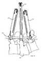
- Figs. 1A and 1Bshow details of how a typical reduction procedure brings into alignment a misaligned vertebra.
- vertebral body 90is out of alignment with the rest of the spine and is to be returned to its original position via a reduction procedure.
- the surgeonconstructs a "framework" or assembly that will serve as the alignment point.
- the surgeonconstructs the framework with pedicle screws or other suitable fasteners and a rod or elongated member to bridge the "bad” (defective or diseased) segment or vertebra and anchoring to the two "good” (healthy and properly aligned) adjacent segments or vertebrae above and below.
- the surgeonplaces fasteners or pedicle screws (collar 112 of the fastener assembly is shown explicitly) into the desired vertebral bodies, including the "bad" segment (labeled 90). Once in place, the surgeon locates an elongated member or rod 104 in the adjacent bone fastener assemblies (e.g., screw heads), and fastens it with a closure mechanism (e.g., closure cap). The rod is contoured in a manner that will hold the proper alignment of the segments or vertebrae once the reduction procedure is complete.
- a closure mechanisme.g., closure cap
- the surgeonuses one or more extenders. Because elongated member or rod 104 passes through the middle extender (labeled 170) in the figure, which is in turn attached to the pedicle screw or fastener of the "bad" segment, the extender serves two purposes. First, the extender acts as a guide for the proper alignment of elongated member or rod 104 into the fastener assembly (e.g., screw head).
- the fastener assemblye.g., screw head
- the extenderalso serves as a mechanism to "pull up” on the fastener or screw and consequently the vertebral body until elongated member or rod 104 is properly seated within the fastener assembly (e.g., screw head). As described below in more detail, this is done by “pushing” incrementally against elongated member or rod 104 with a hollow shaft or tube (see for example item 188 in Figs. 2A and 2B ) while “pulling" up on extender 170 in a manner similar to a tackle being used to hoist up a load.
- reducer(described below in detail). As detailed below, one part of the reducer is releasably coupled to extender 170 via locking member(s), while another part of the reducer (reduction shaft 308) is coupled to shaft or tube 188, which is in turn anchored or coupled to elongated member or rod 104.
- Fig. 1Bshows vertebral body 90 in its reduced state. Note that it is completely or substantially aligned with the rest of the spine or adjacent vertebral bodies.
- a closure mechanismis applied that will secure, fasten, or lock elongated member or rod 104 to the bone fastener assembly (e.g., to the screw head), and therefore fix the position of the "bad" or reduced segment or vertebra 90 with respect to the adjacent segments.
- Bone graftmay be applied to aid fusing the segments together while held in place with elongated member or rod 104 and the bone fastener assemblies.
- the disclosed reduction apparatus and associated methodsovercome those limitations.
- the disclosed reduction apparatus and related techniquesallow incremental reduction without continual surgeon intervention, thus allowing for gradual tissue relaxation, provide relatively extended range of operation or reduction, provide quick-coupling capabilities, and adapt more easily to the patient's anatomy.
- Fig. 2Ashows a shows a system 100 for a spinal surgical operation that uses a reducer according to an exemplary embodiment of the invention.
- System 100includes bone fastener assembly 102 (e.g., screw, collar, and closure member (e.g., cap)), elongated member 104 (e.g., a rod), extender 170, sleeve or assembly 186, and reducer 300.
- bone fastener assembly 102e.g., screw, collar, and closure member (e.g., cap)
- elongated member 104e.g., a rod
- extender 170e.g., a rod
- sleeve or assembly 186e.g., a rod
- extender 170allows the surgeon to manipulate bone fastener assembly 102 and to couple fastener 108 to vertebra 90.
- a distal end of an extender 170couples to bone fastener assembly 102 and allows the surgeon to manipulate assembly 102.
- extender 170couples to collar 112 of assembly 102.
- a drivermay be coupled to a bone fastener of the bone fastener assembly.
- the drivermay be used to insert the bone fastener into vertebral bone, such as vertebra 90.
- Elongated member 104allows the surgeon to accomplish a desired goal, for example, stabilize the spine, maintain the natural spacing between vertebrae, etc., as persons of ordinary skill in the art who have the benefit of the description of the invention understand.
- closure membersmay be secured to the bone fastener assemblies.
- a counter torque wrenchWhen a closure member is threaded on a bone fastener assembly, a counter torque wrench may be used to inhibit the application of torque to the spine of the patient.
- a counter torque wrenchmay hold an extender that is coupled to a collar. The counter torque wrench allows the application of an appropriate or desired amount of torque, for example, to shear off the tool portion of a closure member.
- a counter torque wrenchmay inhibit application of torque to a patient during tightening of a closure member and/or during shearing of a tool portion of the closure member by applying a force to an elongated member to counter the force applied to a bone fastener assembly by rotation of the closure member.
- the counter torque wrenchmay take a variety of forms.
- itmay constitute a sleeve that includes hollow shaft or tube 188.
- Hollow shaft 188may be inserted through an opening in the body over extender 170 and advanced toward the patient's spine.
- Handle 190 of sleeve or assembly 186may have of various shapes or designs, as desired.
- a shape of handle 190may facilitate gripping of sleeve or assembly 186 or hollow tube 188.
- Handle 190may include a cut-out portion to facilitate gripping and/or to reduce the weight of the sleeve.
- a shape of handle 190may be tapered toward hollow shaft 188 to reduce interference and/or increase visibility of a surgical site.
- handle 190includes lock button or mechanism 191.
- lock mechanism 191locks or holds the position of handle 190 with respect to sleeve or assembly 186 or hollow shaft 188.
- the surgeonmay "flip" handle 190 around (i.e., move it along the path shown by arrows labeled A) in order to reduce interference with the patient's body and/or increase visibility of the surgical site.
- reducing one or more vertebral bodies to the shape of an elongated member (e.g., a contoured elongated member) or to a desired positionmay be indicated.
- Reduction of a vertebral body during a spinal stabilization proceduremay include forcing or moving the vertebral body into a position determined by the contour of the elongated member used in the spinal stabilization system or by other indicia.
- a first portion of an elongated membermay be seated in a collar of a first bone fastener assembly that is coupled to a first vertebra.
- a closure membermay be coupled to the collar and the elongated member to seat the elongated member fully in the collar and to fix the position of the elongated member relative to the first bone fastener assembly.
- a second portion of the elongated membermay be positioned adjacent to a collar of a second bone fastener assembly that is coupled to a second vertebra.
- the position of the second vertebra and/or the shape of the elongated membermay inhibit the second portion of the elongated member from being fully seated in the collar of the second bone fastener assembly.
- a reducermay be coupled to the elongated member and to the collar of the second bone fastener assembly (e.g., via extender 170).
- the reducermay be used to reduce the vertebral body, e.g., fully seat the second portion of the elongated member in the collar of the second bone fastener assembly.
- driver 101may be used to secure a closure member (e.g., cap or other suitable item) to the collar to fix the position of the elongated member relative to the collar.
- Radiological imaging or fluoroscopymay be used to determine when the reducer has fully seated the second portion of the elongated member in the collar of the second bone fastener assembly.
- Reducersmay be used during a minimally invasive surgical procedure or during procedures where access to an elongated member and working room are restricted.
- a reducermay be used to pull an extender coupled to a bone fastener assembly of a spinal implant or stabilization system upward (e.g., away from the spine) to seat the elongated member in a collar of the bone fastener assembly.
- Movement of a reducermay be achieved by, but is not limited to being achieved by, use of threading, cam action, linkage arms, or a combination thereof, as described below.
- a reducermay be used with one or more other instruments to achieve reduction of a vertebral body coupled to a spinal stabilization system.
- Fig. 2Adepicts an embodiment of reducer 300 that may be used in combination with extender 170 and sleeve or assembly 186, including hollow shaft 188.
- the reducermay be used to seat elongated member 104 in collar 112 of bone fastener assembly 102 when the bone fastener assembly is coupled to a vertebra.
- the reduceris designed to couple to extender 170 and pull it upward while pushing elongated member 104 into collar 112.
- reduction of vertebral body 90is accomplished by moving vertebral body 90 coupled to bone fastener assembly 102 relative to elongated member 104 in such a manner that the elongated member 104 is captured within collar 112 of bone fastener assembly 102, thus holding vertebral body 90 in desired position.
- the reductionis accomplished by inducing relative motion of elongated member 104 with respect to collar 112 coupled to vertebral body 90 via assembly 102 or vice versa.
- An apparatus for inducing relative motionis reducer 300 with engaging tabs 306 and reduction sleeve 308 that moves with respect to engaging tabs 306.
- Engaging tabs 306are coupled to extender 170, which in turn is coupled to vertebral body 90 via assembly 102.
- Reduction sleeve 308is coupled to hollow shaft 188, which in turn is coupled to elongated member 104.
- shaft 188moves relative to extender 170.
- elongated member 104moves relative to collar 112 of assembly 102, which is coupled to vertebral body 90.
- Fig. 2Bshows elongated member 104 seated into collar 112 of assembly 102 as a result of operating reducer 300 (i.e., as a result of the reduction of vertebra or vertebral body 90, as described below in detail).
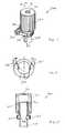
- FIG. 3shows a reducer according to one exemplary embodiment of the invention.
- Reducer 300includes knob or handle 302, locking handles 304, locking or engaging members or tabs 306, reduction sleeve 308, and bore 310.
- Fig. 4shows a top view of locking handles 304 and locking members 306.
- Locking handles 304include or couple to a biasing mechanism, e.g., springs to facilitate engagement of locking members 306 to extender 170. Depressing locking handles 304 causes locking members 306 to withdraw from openings in reduction sleeve 308. Releasing locking handles 304, however, causes locking members 306 to return to their original positions in the openings.
- a biasing mechanisme.g., springs to facilitate engagement of locking members 306 to extender 170. Depressing locking handles 304 causes locking members 306 to withdraw from openings in reduction sleeve 308. Releasing locking handles 304, however, causes locking members 306 to return to their original positions in the openings.
- Fig. 5shows a cross-section of reducer 300. Note that an inner portion or surface of knob 302 includes threads 312. An outer portion or surface of reduction sleeve 308 includes threads 314, which are complementary to threads 312 of knob 302.
- knob 302engages the threads of reduction sleeve 308.
- knob 302By rotating knob 302 along the arrows labeled “B,” one may cause the coupled or engaged threads of knob 302 and reduction sleeve 308 to cause sleeve 308 to move up or down or vertically, as the arrow labeled “C” shows. The movement of sleeve 308 may in turn cause the corresponding motion of other apparatus or items coupled to it.
- reducer 300couples to other surgical apparatus in order to reduce a vertebral body.
- Reducer 300couples to extender 170 (see above) via locking members 306. More specifically, by depressing locking handles 304, the surgeon causes locking members 306 to withdraw or move in an outward direction (away from sleeve 308). The surgeon then couples reducer 300 to extender 170 (e.g., by placing reduction sleeve 308 over or inside extender 170, as desired) and releases locking handles 304, as described above.
- the surgeonmay turn knob 302 in a desired direction and by a desired amount. As described above, the turning of knob 302 causes shaft 188 to move relative to extender 170. As noted, extender 170 is coupled to the bone fastener assembly 102 (see Figs. 2A and 2B ). Consequently, elongated member 104 moves relative to collar 112 of assembly 102, which is coupled to vertebral body 90, hence causing reduction of vertebral body 90.
- reducer 300may activate reducer 300 by a desired amount (by turning knob 302 in a desired direction and by a desired amount). Once the surgeon finishes manipulating reducer 300, it maintains the desired or final reduction.
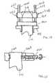
- Fig. 6shows a cross-section of another reducer coupled to extender 170 and hollow shaft 188.
- the reducer in Fig. 6includes knob 302 and body 320.
- Body 320couples to extender 170 through any suitable or desired mechanism, such as locking members 306.
- Body 320has a threaded portion 320A that engages a complementary threaded portion 302A of knob 302.
- Body 320couples to extender 170.
- Turning knob 302 clockwise or counterclockwisecauses body 320 and, hence, extender 170 to move up or down relative to hollow shaft 188.
- the surgeoncan reduce the corresponding vertebral body.
- Fig. 7shows a cross-section of another reducer coupled to extender 170 and hollow shaft 188.
- the reducerincludes knob 302, upper body 322, and lower body 324.
- Upper body 322couples to extender 170 through any suitable or desired mechanism, such as locking members 306. (Note that, alternatively, or in addition, lower body 324 may couple to extender 170, as desired, and as persons of ordinary skill in the art who have the benefit of the description of the invention understand.)
- Upper body 322has a threaded portion 322A that engages a complementary threaded portion 302A of knob 302.
- lower body 324has a threaded portion 324A that couples to threaded portion 302A of knob 302.
- Threaded portion 322A and threaded portion 324Ahave opposite thread directions. For example, in the embodiment shown, threaded portion 322A has right-hand threads, whereas threaded portion 324A has left-hand threads.
- threaded portion 322Amay have left-hand threads and threaded portion 324A has right-hand threads.
- knob 302clockwise or counterclockwise causes upper body 322 and lower body 324 to move in opposite directions.
- extender 170couples to upper body 322 (or lower body 324, as desired)
- movement of upper body 322 (or lower body 324)causes extender 170 to move up or down relative to hollow tube 188.
- the surgeoncan reduce the corresponding vertebral body.
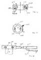
- Fig. 8shows a cross-section of another reducer coupled to extender 170 and hollow shaft 188.
- the reducerincludes knob 302 and body 320.
- Body 320couples to extender 170 through any suitable or desired mechanism, such as locking members 306.
- Body 320has a threaded portion 320A that engages a complementary threaded portion 302A of knob 302. Turning knob 302 clockwise or counterclockwise causes knob 302 to move relative to body 320. Note, however, that turning knob 302 does not change its position relative to extender 170. As extender 170 couples to knob 302, movement of knob 302 causes extender 170 to move up or down relative to hollow tube 188. Thus, by turning knob 302 in a desired direction and by a desired amount, the surgeon can reduce the corresponding vertebral body.
- Fig. 9illustrates a cross-section of another reducer coupled to extender 170 and hollow shaft 188.
- the reducerincludes two progressively inclined members or wedges 350 and 352.
- Progressively inclined wedge 350couples to extender 170 (via, for example, coupling members not shown explicitly).
- Progressively inclined wedge 352couples to hollow shaft 188.
- progressively inclined wedge 350By turning progressively inclined wedge 350 in a desired direction and by a desired amount, while holding progressively inclined wedge 352 stationary (or vice-versa), the surgeon can cause movement of extender 172 and hence reduce the corresponding vertebral body.
- progressively inclined wedges 350 and 352that include steps (rather than a continuously inclining profile) of desired size or height, as desired. Using stepped wedges would allow incremental reduction in discrete amounts or steps.
- Fig. 10depicts a cross-section of another reducer coupled to extender 170 and hollow shaft 188.
- the reducerincludes a "z lever” configuration or assembly.
- the reducerincludes base 364 coupled to hollow shaft 188, and body 320 coupled to extender 170 (e.g., through locking members 306), lever bar 360, and truss 362.
- Lever bar 360couples at joint 367 to truss 362.
- Truss 362couples to base 364 at joint.
- Lever bar 360forms a lever, with a fulcrum at joint 366. The surgeon may lift lever bar 360, thus exerting downward force on truss 362 through joint 367. Truss 362 in turn exerts downward pressure on base 364 and hence on hollow tube 188.
- Lifting lever bar 360also causes the lifting of body 320 and thus extender 170. Consequently, by lifting lever bar 362 by a desired amount, the surgeon can reduce the corresponding vertebral body.
- Fig. 11shows a cross-section of another reducer coupled to extender 170 and hollow shaft 188.
- the reducerincludes base 372 coupled to hollow tube 188, and body 320 coupled to extender 170.
- the reducerfurther includes bolt or screw 370, whose threads engage with threaded portion 320A of body 320.
- An end of screw or bolt 370couples to base 372.
- Slide pin 374couples a portion of body 320 (opposite or distal end from screw or bolt 370 shown in Fig. 11 ) to base 372. Slide pin 374 provides stability to the mechanism and facilitates movement of body 320 with respect to base 372.
- the surgeonmay turn screw or bolt 370, which causes body 320 to move closer to (or farther from, depending on the type of threads of screw or bolt 370 and threaded portion 320A) base 372. Because extender 170 couples to body 320, movement of body 320 causes reduction of the corresponding vertebral body.
- Fig. 12illustrates a cross-section of another reducer coupled to extender 170 and hollow shaft 188.
- the reducerincludes a "scissor jack" configuration or assembly.
- the reducerincludes base 382 coupled to hollow shaft 188, and body 320 coupled to extender 170 (e.g., through locking members 306), lever bar 386, screw or bolt 380, and lever bar 388.
- Lever bar 386 and lever bar 388couple to each other at joint 390A.
- Lever bar 386couples to body 320 at joint 390B and to base 382 at joint 390D.
- lever bar 388couples to body 320 at joint 390C and to body 382 at joint 390E.
- body 320 and base 380couple, respectively, to extender 170 and to hollow shaft 188.
- the lifting of body 320causes the lifting of extender 170 and therefore reduction of the corresponding vertebral body.
- Fig. 13shows a cross-section of another reducer coupled to extender 170 and hollow shaft 188.
- the reducerincludes an offset cam (locking member 306) assembly.
- the reducerincludes body 390 coupled to hollow shaft 188 and disk 392 coupled to extender 170.
- Disk 392couples to one end of shaft 394, which passes through a bore or opening in body 390. Another end of shaft 394 couples to handle or member 396.
- handle or member 396couples to handle or member 396.
- Crank or handle 398couples to member 396 and assists in turning shaft 394 and, hence, disk 392.
- Disk 392couples to extender 170 via locking member 306 (e.g., a cam).
- Locking member 306has an offset location with respect to shaft 394.
- turning shaft 394causes the lifting of extender 170 and, hence, the reduction of the corresponding vertebral body.
- FIG. 14shows a cross section of an exemplary embodiment of a holding device.
- a reducere.g., the reducers in Figs. 9 , 10 , and 13
- extender 170in place (i.e., keep steady or hold constant the degree or amount of reduction).
- the holderincludes base 402 coupled to hollow shaft 188 and body 404 coupled to extender 170.
- Columns or bars 408A and 408Bcoupled body 404 to base 402.
- Body 404may move along the length of columns 408A and 408B.
- Columns 408A and 408Bhave ratcheting teeth 410A and 410B, respectively. Ratcheting teeth 410A and 410B allow upward movement of body 404, but prevent its downward movement. Thus, the holder allows the surgeon to maintain a desired degree or amount of reduction once it is achieved.
- the holderfurther includes release handles or members 406A and 406B.
- release handles or members 406A and 406BBy activating or operating release handles 406A and 406B, the surgeon can cause the release of the ratcheting teeth 410A and 410B, respectively, thus allowing movement of body 404 with respect to base 402.
- the following descriptionprovides some examples of releasable coupling mechanisms that may be used with the reduction apparatus described above.
- Fig. 15shows a cross-section of an attachment mechanism.
- the attachment mechanismincludes locking members 306A and 306B, and screw or bolt 420.
- Locking members 306A and 306Bcouple to extender 170, for example, through notches or other mechanisms in extender 170.
- Locking member 306Ais stationary (e.g., part of the body of a reducer), but locking member 306B may move in response to force applied to it.
- Fig. 16shows a cross-section of other attachment mechanisms.
- the apparatus shown in Fig. 16illustrates two locking mechanisms.
- the locking mechanismsmay be included within housing or member 432, for example, the body of a reducer.
- One locking mechanismincludes locking member 306A.
- Locking member 306Acouples to housing 432 via a joint or hinge 434.
- Hinge 434allows locking member 306A to swing or flip down. In this position, locking member 306A engages and couples to extender 170.
- Hinge 434also allows locking member 306A to swing or flip up. In this position, locking member 306A disengages or uncouples from extender 170.
- the second locking mechanism in Fig. 16includes locking member 306B and biasing member or spring 430.
- Locking member 306Bmay slide within housing 432. When it slides towards extender 170, locking member 306B engages and couples to extender 170. Conversely, when it slides away from extender 170, locking member 306B disengages and uncouples from extender 170.
- Spring 430exerts some force against locking member 306B, which causes it to slide towards and couple to extender 170. When one desires to uncouple extender 170 from locking member 306B, one may slide away or push back locking member 306B from extender 170.
- Fig. 17depicts a cross-section of an attachment mechanism.
- the attachment mechanism in Fig. 17constitutes an "iris type" of mechanism, and includes locking members 306, ring 440, and handle or lever 444.
- Turning handle 444causes movement of locking members 306. More specifically, turning handle 444 in one direction (e.g., clockwise) causes locking members 306 to move towards each other, and thus engage and couple to extender 170. Turning handle 444 in the opposite direction (e.g., counterclockwise), however, causes locking members 306 to move away from each other, and thus disengage and uncouple from extender 170.
- one directione.g., clockwise
- Turning handle 444 in the opposite directione.g., counterclockwise
- Fig. 18depicts a cross-section of an attachment mechanism.
- the attachment mechanism in Fig. 18includes locking members 306, housing 460 (e.g., body or other part of a reducer), shaft 450, and handle 454.
- Handle 454couples to shaft 450 via hinge or joint 452.
- Engaging handle 454e.g., by pulling it towards shaft 450, causes locking members 306 to move in one direction, for example, towards each other. As a result, locking members 306 engage with and couple to extender 170.
- Disengaging handle 454e.g., by pulling it away from shaft 450, causes locking members 306 to move in the opposite direction, for example, away each other. As a result, locking members 306 disengage and uncouple from extender 170.
- Fig. 19depicts a cross-section of an attachment mechanism.
- the attachment mechanism in Fig. 19constitutes a "collet type includes locking members 306, sleeves 472, and engaging members 474.
- Fig. 19shows one attachment mechanism in the locked position (the right side of Fig. 19 ), and another attachment mechanism in the unlocked position (left side of Fig. 19 ).
- Each of locking members 306may move around a respective joint or hinge 474.
- moving sleeves 472causes engaging members 472 to contact locking members 306, form a collar or collet around them, and cause them to move. Movement of locking members 306 may cause them to engage and couple to extender 170, or to disengage and uncouple from extender 170. Note that the apparatus in Fig. 19 allows the surgeon to couple either side of the reducer to extender 170 independently of the other side.
- the embodiments of reducers according to the inventive conceptsuse threaded mechanisms or portions.
- a desired thread type and/or pitchone may provide reducers with desired characteristics, as persons of ordinary skill in the art who have the benefit of the description of the invention understand.
- a relatively fine thread pitchby using a relatively fine thread pitch, one may produce a reducer that causes a relatively small amount of reduction for a given amount of activation of the reducer (e.g., turning knob 302 in Fig. 3 ), and vice-versa.
- relatively fine thread pitchesone may allow the surgeon to fine-tune the reduction of the vertebral bodies with a relatively high degree of precision.
- reducersby varying the size or length of the threaded portion, one may produce reducers with desired characteristics. For example, a relatively long or large threaded portion would allow a relatively large reduction of the vertebral body, and vice-versa. This property allows reducers according to the inventive concepts to overcome the limited range of conventional reducers.
Landscapes
- Health & Medical Sciences (AREA)
- Orthopedic Medicine & Surgery (AREA)
- Surgery (AREA)
- Life Sciences & Earth Sciences (AREA)
- Neurology (AREA)
- Medical Informatics (AREA)
- Biomedical Technology (AREA)
- Heart & Thoracic Surgery (AREA)
- Engineering & Computer Science (AREA)
- Molecular Biology (AREA)
- Animal Behavior & Ethology (AREA)
- General Health & Medical Sciences (AREA)
- Public Health (AREA)
- Veterinary Medicine (AREA)
- Nuclear Medicine, Radiotherapy & Molecular Imaging (AREA)
- Surgical Instruments (AREA)
- Prostheses (AREA)
Description
- The present invention generally relates to apparatus used during a spinal surgical procedure for reducing vertebral bodies.
- Modem spine surgery often involves the use of spinal implants to correct or treat various spine disorders or to support the spine. Spinal implants may help, for example, to stabilize the spine, correct deformities of the spine, facilitate fusion, treat spinal fractures, repair annular defects, etc.
- Spinal implant systems for a lumbar region of the spine may be inserted during a procedure using a posterior spinal approach. Conventional systems and methods for such operations may involve dissecting and retracting soft tissue near or around the surgical site, which may cause trauma to the soft tissue, and extend recovery time.
- Minimally invasive procedures and systems may reduce recovery time as well as trauma to the soft tissue surrounding a stabilization site. During minimally invasive surgical procedures, often a reduction of one of more vertebrae are indicated. A need exists for reduction apparatus and related methods that provide flexibility of operation, enhanced range of reduction, and adaptability to the patient's anatomy.
US 2006/0095035 A1 discloses a spinal reduction apparatus comprising a reducer, comprising a sleeve having a threaded portion and openings. Said threaded portion is in engagement with a threaded portion of a knob of said reducer. The apparatus further comprises an extender coupled releasably to the reducer.- The disclosed inventive concepts relate to apparatus for reduction of vertebrae or vertebral bodies.An apparatus according to the invention includes a reducer, and an extender coupled releasably to the reducer. The reducer includes a sleeve and a knob. The sleeve has a threaded portion. Similarly, the knob has a threaded portion that is in engagement with the threaded portion of the sleeve to provide reduction of the vertebra or vertebral body.
- A system for reducing a vertebra or vertebral body includes an extender and a reducer. The reducer is releasably coupled to the extender, and is configured to allow incremental reduction of the vertebral body.
- Further, a method of reducing a vertebra or vertebral body is disclosed (not part of the invention). The method includes moving incrementally one member with respect to a second member. The first member is releasably coupled to the vertebra, which results in the reduction of the vertebra or vertebral body.
- The appended drawings illustrate only exemplary embodiments of the invention and therefore should not be considered or construed as limiting its scope. Persons of ordinary skill in the art who have the benefit of the description of the invention appreciate that the disclosed inventive concepts lend themselves to other equally effective embodiments. Unless noted otherwise, in the drawings, the same numeral designators used in more than one drawing denote the same, similar, or equivalent functionality, components, or blocks.
- Figs. IA and IB show details of how a typical reduction procedure brings into alignment a misaligned vertebra.
Fig. 2A shows a system for a spinal surgical operation that uses a reducer according to an exemplary embodiment of the invention.Fig. 2B illustrates reduction of a vertebral body by operating the reducer shown inFig. 2A .Fig. 3 depicts a reducer according to one exemplary embodiment of the invention.Fig. 4 shows a top view of the locking handles and locking members of the reducer inFig. 3 .Fig. 5 illustrates a cross-section of the exemplary reducer illustrated inFig. 3 .Figs. 6-13 depict a plurality of exemplary reducers.Fig. 14 shows a holding device.Figs. 15-19 illustrate a plurality of attachment mechanisms.- The disclosed novel concepts relate to apparatus for reducing vertebrae or vertebral bodies during minimally invasive surgical procedures, for example, during a spinal stabilization procedure. Details of minimally invasive surgery are described in detail in U.S. Patent Application
US 2006/0095035 A1 , titled "Instruments and Methods for Reduction of Vertebral Bodies," attorney docket number 7769US01, filed on November 3, 2004. Briefly, minimally invasive surgery uses apparatus such as guide wires, bone fastener assemblies, extenders, and sleeves, as described in detail in U.S. Patent ApplicationUS 2006/0095035 A1 , referenced above. - During minimally invasive surgery, a reduction of one or more vertebral bodies is indicated. As persons of ordinary skill in the art who have the benefit of the description of the invention understand, reduction generally refers to the replacement or realignment of a body part in normal position or restoration of a bodily condition to normal.
Figs. 1A and1B show details of how a typical reduction procedure brings into alignment a misaligned vertebra. - More specifically, in
Fig. 1A ,vertebral body 90 is out of alignment with the rest of the spine and is to be returned to its original position via a reduction procedure. To do so, the surgeon constructs a "framework" or assembly that will serve as the alignment point. The surgeon constructs the framework with pedicle screws or other suitable fasteners and a rod or elongated member to bridge the "bad" (defective or diseased) segment or vertebra and anchoring to the two "good" (healthy and properly aligned) adjacent segments or vertebrae above and below. - The surgeon places fasteners or pedicle screws (
collar 112 of the fastener assembly is shown explicitly) into the desired vertebral bodies, including the "bad" segment (labeled 90). Once in place, the surgeon locates an elongated member orrod 104 in the adjacent bone fastener assemblies (e.g., screw heads), and fastens it with a closure mechanism (e.g., closure cap). The rod is contoured in a manner that will hold the proper alignment of the segments or vertebrae once the reduction procedure is complete. - To aid in the reduction, the surgeon uses one or more extenders. Because elongated member or
rod 104 passes through the middle extender (labeled 170) in the figure, which is in turn attached to the pedicle screw or fastener of the "bad" segment, the extender serves two purposes. First, the extender acts as a guide for the proper alignment of elongated member orrod 104 into the fastener assembly (e.g., screw head). - The extender also serves as a mechanism to "pull up" on the fastener or screw and consequently the vertebral body until elongated member or
rod 104 is properly seated within the fastener assembly (e.g., screw head). As described below in more detail, this is done by "pushing" incrementally against elongated member orrod 104 with a hollow shaft or tube (see forexample item 188 inFigs. 2A and2B ) while "pulling" up onextender 170 in a manner similar to a tackle being used to hoist up a load. - This incremental, controlled relative motion is achieved by reducer (described below in detail). As detailed below, one part of the reducer is releasably coupled to extender 170 via locking member(s), while another part of the reducer (reduction shaft 308) is coupled to shaft or
tube 188, which is in turn anchored or coupled to elongated member orrod 104. Fig. 1B showsvertebral body 90 in its reduced state. Note that it is completely or substantially aligned with the rest of the spine or adjacent vertebral bodies. At this stage, a closure mechanism is applied that will secure, fasten, or lock elongated member orrod 104 to the bone fastener assembly (e.g., to the screw head), and therefore fix the position of the "bad" or reduced segment orvertebra 90 with respect to the adjacent segments. Bone graft may be applied to aid fusing the segments together while held in place with elongated member orrod 104 and the bone fastener assemblies.- Conventional reducers have a number of disadvantages, such as relatively limited range of operation, relative lack of adaptability to the patient's anatomy (e.g., the patient's lordotic curve), failing to allow for incremental reduction, and involving manual interaction by the surgeon at all times or substantially all times, etc.
- As described here in detail, the disclosed reduction apparatus and associated methods overcome those limitations. For example, the disclosed reduction apparatus and related techniques allow incremental reduction without continual surgeon intervention, thus allowing for gradual tissue relaxation, provide relatively extended range of operation or reduction, provide quick-coupling capabilities, and adapt more easily to the patient's anatomy.
Fig. 2A shows a shows asystem 100 for a spinal surgical operation that uses a reducer according to an exemplary embodiment of the invention.System 100 includes bone fastener assembly 102 (e.g., screw, collar, and closure member (e.g., cap)), elongated member 104 (e.g., a rod),extender 170, sleeve or assembly 186, andreducer 300. Some details ofsystem 100 are provided in U.S. Patent ApplicationUS 2006/0095035 A1 , referenced above.- During minimally invasive surgery,
extender 170 allows the surgeon to manipulatebone fastener assembly 102 and to couplefastener 108 tovertebra 90. A distal end of anextender 170 couples tobone fastener assembly 102 and allows the surgeon to manipulateassembly 102. In the embodiment shown,extender 170 couples tocollar 112 ofassembly 102. - After a bone fastener assembly is coupled to
extender 170, a driver may be coupled to a bone fastener of the bone fastener assembly. The driver may be used to insert the bone fastener into vertebral bone, such asvertebra 90. Elongated member 104 allows the surgeon to accomplish a desired goal, for example, stabilize the spine, maintain the natural spacing between vertebrae, etc., as persons of ordinary skill in the art who have the benefit of the description of the invention understand. After bone fastener assemblies are installed and an elongated member is placed in the bone fastener assemblies, closure members may be secured to the bone fastener assemblies.- When a closure member is threaded on a bone fastener assembly, a counter torque wrench may be used to inhibit the application of torque to the spine of the patient. A counter torque wrench may hold an extender that is coupled to a collar. The counter torque wrench allows the application of an appropriate or desired amount of torque, for example, to shear off the tool portion of a closure member.
- In some embodiments, a counter torque wrench may inhibit application of torque to a patient during tightening of a closure member and/or during shearing of a tool portion of the closure member by applying a force to an elongated member to counter the force applied to a bone fastener assembly by rotation of the closure member.
- The counter torque wrench may take a variety of forms. For example, it may constitute a sleeve that includes hollow shaft or
tube 188.Hollow shaft 188 may be inserted through an opening in the body overextender 170 and advanced toward the patient's spine. - Handle 190 of sleeve or assembly 186 may have of various shapes or designs, as desired. In some embodiments, a shape of
handle 190 may facilitate gripping of sleeve or assembly 186 orhollow tube 188. Handle 190 may include a cut-out portion to facilitate gripping and/or to reduce the weight of the sleeve. In certain embodiments, a shape ofhandle 190 may be tapered towardhollow shaft 188 to reduce interference and/or increase visibility of a surgical site. - In the embodiment shown, handle 190 includes lock button or
mechanism 191. During normal operation,lock mechanism 191 locks or holds the position ofhandle 190 with respect to sleeve or assembly 186 orhollow shaft 188. By pulling backlock button 191, the surgeon may "flip" handle 190 around (i.e., move it along the path shown by arrows labeled A) in order to reduce interference with the patient's body and/or increase visibility of the surgical site. - In some embodiments, reducing one or more vertebral bodies to the shape of an elongated member (e.g., a contoured elongated member) or to a desired position may be indicated. Reduction of a vertebral body during a spinal stabilization procedure may include forcing or moving the vertebral body into a position determined by the contour of the elongated member used in the spinal stabilization system or by other indicia.
- During a spinal stabilization or implant procedure, a first portion of an elongated member may be seated in a collar of a first bone fastener assembly that is coupled to a first vertebra. A closure member may be coupled to the collar and the elongated member to seat the elongated member fully in the collar and to fix the position of the elongated member relative to the first bone fastener assembly.
- A second portion of the elongated member may be positioned adjacent to a collar of a second bone fastener assembly that is coupled to a second vertebra. The position of the second vertebra and/or the shape of the elongated member, however, may inhibit the second portion of the elongated member from being fully seated in the collar of the second bone fastener assembly.
- A reducer may be coupled to the elongated member and to the collar of the second bone fastener assembly (e.g., via extender 170). The reducer may be used to reduce the vertebral body, e.g., fully seat the second portion of the elongated member in the collar of the second bone fastener assembly.
- While the reducer holds the second portion of the elongated member seated in the collar of the second bone fastener assembly,
driver 101 may be used to secure a closure member (e.g., cap or other suitable item) to the collar to fix the position of the elongated member relative to the collar. Radiological imaging or fluoroscopy may be used to determine when the reducer has fully seated the second portion of the elongated member in the collar of the second bone fastener assembly. - Reducers may be used during a minimally invasive surgical procedure or during procedures where access to an elongated member and working room are restricted. During a minimally invasive procedure or a procedure with limited access and/or limited working room, a reducer may be used to pull an extender coupled to a bone fastener assembly of a spinal implant or stabilization system upward (e.g., away from the spine) to seat the elongated member in a collar of the bone fastener assembly. Movement of a reducer may be achieved by, but is not limited to being achieved by, use of threading, cam action, linkage arms, or a combination thereof, as described below.
- In some embodiments, a reducer may be used with one or more other instruments to achieve reduction of a vertebral body coupled to a spinal stabilization system.
Fig. 2A depicts an embodiment ofreducer 300 that may be used in combination withextender 170 and sleeve or assembly 186, includinghollow shaft 188. - The reducer may be used to seat
elongated member 104 incollar 112 ofbone fastener assembly 102 when the bone fastener assembly is coupled to a vertebra. The reducer is designed to couple toextender 170 and pull it upward while pushingelongated member 104 intocollar 112. - Without loss of generality, in one embodiment, reduction of
vertebral body 90 is accomplished by movingvertebral body 90 coupled tobone fastener assembly 102 relative toelongated member 104 in such a manner that theelongated member 104 is captured withincollar 112 ofbone fastener assembly 102, thus holdingvertebral body 90 in desired position. The reduction is accomplished by inducing relative motion ofelongated member 104 with respect tocollar 112 coupled tovertebral body 90 viaassembly 102 or vice versa. - An apparatus for inducing relative motion is
reducer 300 with engagingtabs 306 andreduction sleeve 308 that moves with respect to engagingtabs 306. Engagingtabs 306 are coupled toextender 170, which in turn is coupled tovertebral body 90 viaassembly 102.Reduction sleeve 308 is coupled tohollow shaft 188, which in turn is coupled toelongated member 104. By manipulatingreduction sleeve 308 with respect to engagingtabs 306,shaft 188 moves relative toextender 170. As a consequence,elongated member 104 moves relative tocollar 112 ofassembly 102, which is coupled tovertebral body 90. - Note that the reduction apparatus uses
shaft 188 and theextender 170 in order to "reach" through a small incision into the patient and manipulateelongated member 104 with respect tovertebral body 90.Fig. 2B showselongated member 104 seated intocollar 112 ofassembly 102 as a result of operating reducer 300 (i.e., as a result of the reduction of vertebra orvertebral body 90, as described below in detail). Fig. 3 shows a reducer according to one exemplary embodiment of the invention.Reducer 300 includes knob or handle 302, locking handles 304, locking or engaging members ortabs 306,reduction sleeve 308, and bore 310.Fig. 4 shows a top view of locking handles 304 and lockingmembers 306. Locking handles 304 include or couple to a biasing mechanism, e.g., springs to facilitate engagement of lockingmembers 306 toextender 170. Depressing locking handles 304causes locking members 306 to withdraw from openings inreduction sleeve 308. Releasing locking handles 304, however, causes lockingmembers 306 to return to their original positions in the openings.Fig. 5 shows a cross-section ofreducer 300. Note that an inner portion or surface ofknob 302 includesthreads 312. An outer portion or surface ofreduction sleeve 308 includesthreads 314, which are complementary tothreads 312 ofknob 302.- Once assembled, the threads of
knob 302 engage the threads ofreduction sleeve 308. By rotatingknob 302 along the arrows labeled "B," one may cause the coupled or engaged threads ofknob 302 andreduction sleeve 308 to causesleeve 308 to move up or down or vertically, as the arrow labeled "C" shows. The movement ofsleeve 308 may in turn cause the corresponding motion of other apparatus or items coupled to it. - During minimally invasive surgery,
reducer 300 couples to other surgical apparatus in order to reduce a vertebral body.Reducer 300 couples to extender 170 (see above) via lockingmembers 306. More specifically, by depressing locking handles 304, the surgeon causes lockingmembers 306 to withdraw or move in an outward direction (away from sleeve 308). The surgeon then couplesreducer 300 to extender 170 (e.g., by placingreduction sleeve 308 over orinside extender 170, as desired) andreleases locking handles 304, as described above. - Once
reducer 300 has coupled toextender 170, the surgeon may turnknob 302 in a desired direction and by a desired amount. As described above, the turning ofknob 302 causesshaft 188 to move relative toextender 170. As noted,extender 170 is coupled to the bone fastener assembly 102 (seeFigs. 2A and2B ). Consequently,elongated member 104 moves relative tocollar 112 ofassembly 102, which is coupled tovertebral body 90, hence causing reduction ofvertebral body 90. - By using relatively fine thread pitches, one may allow the surgeon to fine-tune the reduction of the vertebral bodies, as desired. For example, the surgeon may accomplish the reduction through relatively small or incremental steps. This approach provides the benefit of allowing the affected tissue to relax and helps to reduce trauma.
- Furthermore, under normal circumstances, the surgeon need not continually manipulate
reducer 300. Put another way, the surgeon may activatereducer 300 by a desired amount (by turningknob 302 in a desired direction and by a desired amount). Once the surgeon finishes manipulatingreducer 300, it maintains the desired or final reduction. Fig. 6 shows a cross-section of another reducer coupled toextender 170 andhollow shaft 188. The reducer inFig. 6 includesknob 302 andbody 320.Body 320 couples toextender 170 through any suitable or desired mechanism, such as lockingmembers 306.Body 320 has a threadedportion 320A that engages a complementary threadedportion 302A ofknob 302.Body 320 couples toextender 170. Turningknob 302 clockwise or counterclockwise causesbody 320 and, hence,extender 170 to move up or down relative tohollow shaft 188. As a result, by turningknob 302 in a desired direction and by a desired amount, the surgeon can reduce the corresponding vertebral body.Fig. 7 shows a cross-section of another reducer coupled toextender 170 andhollow shaft 188. The reducer includesknob 302,upper body 322, andlower body 324.Upper body 322 couples toextender 170 through any suitable or desired mechanism, such as lockingmembers 306. (Note that, alternatively, or in addition,lower body 324 may couple toextender 170, as desired, and as persons of ordinary skill in the art who have the benefit of the description of the invention understand.)Upper body 322 has a threaded portion 322A that engages a complementary threadedportion 302A ofknob 302. Similarly,lower body 324 has a threadedportion 324A that couples to threadedportion 302A ofknob 302. Threaded portion 322A and threadedportion 324A have opposite thread directions. For example, in the embodiment shown, threaded portion 322A has right-hand threads, whereas threadedportion 324A has left-hand threads.- Of course, as persons of ordinary skill in the art who have the benefit of the description of the invention understand, one may use other arrangements of threads. For example, in one embodiment, threaded portion 322A may have left-hand threads and threaded
portion 324A has right-hand threads. - Turning
knob 302 clockwise or counterclockwise causesupper body 322 andlower body 324 to move in opposite directions. Asextender 170 couples to upper body 322 (orlower body 324, as desired), movement of upper body 322 (or lower body 324) causesextender 170 to move up or down relative tohollow tube 188. As a result, by turningknob 302 in a desired direction and by a desired amount, the surgeon can reduce the corresponding vertebral body. Fig. 8 shows a cross-section of another reducer coupled toextender 170 andhollow shaft 188. The reducer includesknob 302 andbody 320.Body 320 couples toextender 170 through any suitable or desired mechanism, such as lockingmembers 306.Body 320 has a threadedportion 320A that engages a complementary threadedportion 302A ofknob 302. Turningknob 302 clockwise or counterclockwise causesknob 302 to move relative tobody 320. Note, however, that turningknob 302 does not change its position relative toextender 170. Asextender 170 couples toknob 302, movement ofknob 302 causesextender 170 to move up or down relative tohollow tube 188. Thus, by turningknob 302 in a desired direction and by a desired amount, the surgeon can reduce the corresponding vertebral body.Fig. 9 illustrates a cross-section of another reducer coupled toextender 170 andhollow shaft 188. The reducer includes two progressively inclined members orwedges inclined wedge 350 couples to extender 170 (via, for example, coupling members not shown explicitly). Progressivelyinclined wedge 352 couples tohollow shaft 188.- By turning progressively
inclined wedge 350 in a desired direction and by a desired amount, while holding progressivelyinclined wedge 352 stationary (or vice-versa), the surgeon can cause movement of extender 172 and hence reduce the corresponding vertebral body. Note that one may use a variety of implementations of the reducer, as persons of ordinary skill in the art who have the benefit of the description of the invention understand. For example, one may use progressively inclinedwedges Fig. 10 depicts a cross-section of another reducer coupled toextender 170 andhollow shaft 188. The reducer includes a "z lever" configuration or assembly. Specifically, the reducer includesbase 364 coupled tohollow shaft 188, andbody 320 coupled to extender 170 (e.g., through locking members 306),lever bar 360, andtruss 362.Lever bar 360 couples at joint 367 totruss 362.Truss 362 couples to base 364 at joint.Lever bar 360 forms a lever, with a fulcrum at joint 366. The surgeon may liftlever bar 360, thus exerting downward force ontruss 362 through joint 367.Truss 362 in turn exerts downward pressure onbase 364 and hence onhollow tube 188. Liftinglever bar 360 also causes the lifting ofbody 320 and thusextender 170. Consequently, by liftinglever bar 362 by a desired amount, the surgeon can reduce the corresponding vertebral body.Fig. 11 shows a cross-section of another reducer coupled toextender 170 andhollow shaft 188. The reducer includesbase 372 coupled tohollow tube 188, andbody 320 coupled toextender 170.- The reducer further includes bolt or screw 370, whose threads engage with threaded
portion 320A ofbody 320. An end of screw or bolt 370 couples tobase 372.Slide pin 374 couples a portion of body 320 (opposite or distal end from screw or bolt 370 shown inFig. 11 ) tobase 372.Slide pin 374 provides stability to the mechanism and facilitates movement ofbody 320 with respect tobase 372. - The surgeon may turn screw or bolt 370, which causes
body 320 to move closer to (or farther from, depending on the type of threads of screw or bolt 370 and threadedportion 320A)base 372. Becauseextender 170 couples tobody 320, movement ofbody 320 causes reduction of the corresponding vertebral body. Fig. 12 illustrates a cross-section of another reducer coupled toextender 170 andhollow shaft 188. The reducer includes a "scissor jack" configuration or assembly. Specifically, the reducer includesbase 382 coupled tohollow shaft 188, andbody 320 coupled to extender 170 (e.g., through locking members 306),lever bar 386, screw or bolt 380, andlever bar 388.Lever bar 386 andlever bar 388 couple to each other at joint 390A.Lever bar 386 couples tobody 320 at joint 390B and to base 382 at joint 390D. Similarly,lever bar 388 couples tobody 320 at joint 390C and tobody 382 at joint 390E. By turning screw or bolt 380, the surgeon causes the location of joint 390C to move throughslot 320A and the location of joint 390D to move throughslot 382A, thus liftingbody 320 with respect tobase 380.- As noted,
body 320 andbase 380 couple, respectively, toextender 170 and tohollow shaft 188. Thus, the lifting ofbody 320 causes the lifting ofextender 170 and therefore reduction of the corresponding vertebral body. Fig. 13 shows a cross-section of another reducer coupled toextender 170 andhollow shaft 188. Generally speaking, the reducer includes an offset cam (locking member 306) assembly.- The reducer includes
body 390 coupled tohollow shaft 188 anddisk 392 coupled toextender 170.Disk 392 couples to one end ofshaft 394, which passes through a bore or opening inbody 390. Another end ofshaft 394 couples to handle ormember 396. Note that, rather than separate pieces (e.g.,disk 392,shaft 394, and member 396), one may integrate or combine one or more of the components shown inFig. 13 . As merely one example, one may combineshaft 396 anddisk 392 as one component. - Crank or handle 398 couples to
member 396 and assists in turningshaft 394 and, hence,disk 392.Disk 392 couples toextender 170 via locking member 306 (e.g., a cam). Lockingmember 306 has an offset location with respect toshaft 394. Thus, turningshaft 394 causes the lifting ofextender 170 and, hence, the reduction of the corresponding vertebral body. - Another aspect of the invention relates to holding devices suitable for use with reducers according to various embodiments of the invention.
Fig. 14 shows a cross section of an exemplary embodiment of a holding device. One may use the holder in conjunction or in combination with a reducer (e.g., the reducers inFigs. 9 ,10 , and13 ) in order to holdextender 170 in place (i.e., keep steady or hold constant the degree or amount of reduction). - The holder includes
base 402 coupled tohollow shaft 188 andbody 404 coupled toextender 170. Columns or bars 408A and 408B coupledbody 404 tobase 402.Body 404 may move along the length ofcolumns 408A and 408B.Columns 408A and 408B have ratchetingteeth 410A and 410B, respectively. Ratchetingteeth 410A and 410B allow upward movement ofbody 404, but prevent its downward movement. Thus, the holder allows the surgeon to maintain a desired degree or amount of reduction once it is achieved. - The holder further includes release handles or members 406A and 406B. By activating or operating release handles 406A and 406B, the surgeon can cause the release of the ratcheting
teeth 410A and 410B, respectively, thus allowing movement ofbody 404 with respect tobase 402. - One may use a variety of mechanisms to couple the reducers according to the invention with
extender 170, as persons of ordinary skill in the art who have the benefit of the description of the invention understand. As one specific case, one may couple the reducer to the extender in a releasable manner, such that the surgeon need not reverse some of the reduction procedure steps in order to decouple or release the reducer from the extender. The following description provides some examples of releasable coupling mechanisms that may be used with the reduction apparatus described above. Fig. 15 shows a cross-section of an attachment mechanism. The attachment mechanism includes lockingmembers bolt 420. Lockingmembers extender 170, for example, through notches or other mechanisms inextender 170. Lockingmember 306A is stationary (e.g., part of the body of a reducer), but lockingmember 306B may move in response to force applied to it.- More specifically, by turning screw or bolt 420, one may cause it to contact and exert force against locking
member 306B. Force applied against lockingmember 306B causes it to engageextender 170 and couple to it. Thus, by using the attachment mechanism, one may securely couple the reducer or other desired apparatus toextender 170 in order to perform the reduction procedure. Fig. 16 shows a cross-section of other attachment mechanisms. The apparatus shown inFig. 16 illustrates two locking mechanisms. The locking mechanisms may be included within housing ormember 432, for example, the body of a reducer.- One locking mechanism includes locking
member 306A. Lockingmember 306A couples tohousing 432 via a joint or hinge 434.Hinge 434 allows lockingmember 306A to swing or flip down. In this position, lockingmember 306A engages and couples toextender 170. Hinge 434 also allows lockingmember 306A to swing or flip up. In this position, lockingmember 306A disengages or uncouples fromextender 170. - The second locking mechanism in
Fig. 16 includes lockingmember 306B and biasing member orspring 430. Lockingmember 306B may slide withinhousing 432. When it slides towardsextender 170, lockingmember 306B engages and couples toextender 170. Conversely, when it slides away fromextender 170, lockingmember 306B disengages and uncouples fromextender 170. Spring 430 exerts some force against lockingmember 306B, which causes it to slide towards and couple toextender 170. When one desires to uncoupleextender 170 from lockingmember 306B, one may slide away or push back lockingmember 306B fromextender 170.Fig. 17 depicts a cross-section of an attachment mechanism. The attachment mechanism inFig. 17 constitutes an "iris type" of mechanism, and includes lockingmembers 306,ring 440, and handle orlever 444.- Turning
handle 444 causes movement of lockingmembers 306. More specifically, turninghandle 444 in one direction (e.g., clockwise) causes lockingmembers 306 to move towards each other, and thus engage and couple toextender 170. Turninghandle 444 in the opposite direction (e.g., counterclockwise), however, causes lockingmembers 306 to move away from each other, and thus disengage and uncouple fromextender 170. Fig. 18 depicts a cross-section of an attachment mechanism. The attachment mechanism inFig. 18 includes lockingmembers 306, housing 460 (e.g., body or other part of a reducer),shaft 450, and handle 454.- Handle 454 couples to
shaft 450 via hinge or joint 452.Engaging handle 454, e.g., by pulling it towardsshaft 450,causes locking members 306 to move in one direction, for example, towards each other. As a result, lockingmembers 306 engage with and couple toextender 170. - Disengaging handle 454, e.g., by pulling it away from
shaft 450,causes locking members 306 to move in the opposite direction, for example, away each other. As a result, lockingmembers 306 disengage and uncouple fromextender 170. - Note that one may include in the apparatus shown in
Fig. 18 mechanisms for holdinghandle 454 in a desired position, as desired, and as persons of ordinary skill in the art who have the benefit of the description of the invention understand. Examples of such mechanisms include ratchets, holding clamps, etc. Fig. 19 depicts a cross-section of an attachment mechanism. The attachment mechanism inFig. 19 constitutes a "collet type includes lockingmembers 306,sleeves 472, and engagingmembers 474.Fig. 19 shows one attachment mechanism in the locked position (the right side ofFig. 19 ), and another attachment mechanism in the unlocked position (left side ofFig. 19 ).- Each of locking
members 306 may move around a respective joint or hinge 474. Generally, movingsleeves 472causes engaging members 472 to contact lockingmembers 306, form a collar or collet around them, and cause them to move. Movement of lockingmembers 306 may cause them to engage and couple toextender 170, or to disengage and uncouple fromextender 170. Note that the apparatus inFig. 19 allows the surgeon to couple either side of the reducer to extender 170 independently of the other side. - As described, the embodiments of reducers according to the inventive concepts use threaded mechanisms or portions. By using a desired thread type and/or pitch, one may provide reducers with desired characteristics, as persons of ordinary skill in the art who have the benefit of the description of the invention understand.
- For example, by using a relatively fine thread pitch, one may produce a reducer that causes a relatively small amount of reduction for a given amount of activation of the reducer (e.g., turning
knob 302 inFig. 3 ), and vice-versa. As noted, by using relatively fine thread pitches, one may allow the surgeon to fine-tune the reduction of the vertebral bodies with a relatively high degree of precision. - Furthermore, by varying the size or length of the threaded portion, one may produce reducers with desired characteristics. For example, a relatively long or large threaded portion would allow a relatively large reduction of the vertebral body, and vice-versa. This property allows reducers according to the inventive concepts to overcome the limited range of conventional reducers.
- Various modifications and alternative embodiments of the invention in addition to those described here will be apparent to persons of ordinary skill in the art who have the benefit of the description of the invention. Accordingly, the manner of carrying out the invention as shown and described are to be construed as illustrative only.
- Persons skilled in the art may make various changes in the shape, size, number, and/or arrangement of parts without departing from the scope of the invention as defined in the claims.
Claims (9)
- A spinal reduction apparatus, comprising:- a reducer (300), comprising a sleeve (308) having a threaded portion (314) and openings, wherein said threaded portion (314) of said sleeve (308) is in engagement with a threaded portion of a knob (302) of said reducer, wherein turning the knob (302) in a first direction causes the sleeve (308) to extend; and- an extender (170) coupled releasably to the reducer (300),characterized in that
the reducer (300) further comprises locking handles (304) coupled to locking members (306), wherein the locking members (306) are configured to be selectively coupled to the extender (170), wherein the sleeve (308) is configured to couple to the extender (170) via said locking members (306) when said locking members (306) are in position in said openings in said sleeve (308), and wherein depressing locking handles (304) causes locking members (306) to withdraw from said openings in said sleeve (308). - The apparatus according to claim 1, wherein turning the knob (302) in a second direction causes the sleeve (308) to retract.
- The apparatus according to claim 1, wherein the reducer (300) further comprises a holding apparatus configured to hold an amount of reduction.
- A system (100) for reducing a vertebral body (90), comprising:an extender (170); anda reducer (300) in accordance with any one of the preceding claims, releasably coupled to the extender wherein the reducer (300) is configured to allow incremental reduction of the vertebral body (90).
- The system (100) according to claim 4, further comprising a bone fastener assembly (102) coupled to the extender (170) and the vertebral body (90).
- The system (100) according to claim 5, further comprising a hollow shaft (188) that surrounds at least a part of the extender (170).
- The system (100) according to claim 6, further comprising a handle (190) coupled to the hollow shaft (188).
- The system (100) according to claim 7, wherein a position of the handle (190) with respect to the hollow shaft (188) is adjustable.
- The system (100) according to claim 5, further comprising an elongated member (104) configured to couple to the bone fastener assembly (102) when the vertebral body (90) is reduced.
Applications Claiming Priority (2)
| Application Number | Priority Date | Filing Date | Title |
|---|---|---|---|
| US11/567,889US8679128B2 (en) | 2006-12-07 | 2006-12-07 | Apparatus and methods for reduction of vertebral bodies in a spine |
| PCT/US2007/085160WO2008070442A1 (en) | 2006-12-07 | 2007-11-20 | Apparatus and methods for reduction of vertebral bodies in a spine |
Publications (2)
| Publication Number | Publication Date |
|---|---|
| EP2120755A1 EP2120755A1 (en) | 2009-11-25 |
| EP2120755B1true EP2120755B1 (en) | 2015-09-16 |
Family
ID=39167706
Family Applications (1)
| Application Number | Title | Priority Date | Filing Date |
|---|---|---|---|
| EP07854710.6ANot-in-forceEP2120755B1 (en) | 2006-12-07 | 2007-11-20 | Apparatus for reduction of vertebral bodies in a spine |
Country Status (3)
| Country | Link |
|---|---|
| US (5) | US8679128B2 (en) |
| EP (1) | EP2120755B1 (en) |
| WO (1) | WO2008070442A1 (en) |
Families Citing this family (59)
| Publication number | Priority date | Publication date | Assignee | Title |
|---|---|---|---|---|
| US20060095035A1 (en)* | 2004-11-03 | 2006-05-04 | Jones Robert J | Instruments and methods for reduction of vertebral bodies |
| DE102005003632A1 (en) | 2005-01-20 | 2006-08-17 | Fraunhofer-Gesellschaft zur Förderung der angewandten Forschung e.V. | Catheter for the transvascular implantation of heart valve prostheses |
| US20070213813A1 (en) | 2005-12-22 | 2007-09-13 | Symetis Sa | Stent-valves for valve replacement and associated methods and systems for surgery |
| US8048089B2 (en) | 2005-12-30 | 2011-11-01 | Edge Systems Corporation | Apparatus and methods for treating the skin |
| US8679128B2 (en)* | 2006-12-07 | 2014-03-25 | Zimmer Spine, Inc. | Apparatus and methods for reduction of vertebral bodies in a spine |
| US7896915B2 (en) | 2007-04-13 | 2011-03-01 | Jenavalve Technology, Inc. | Medical device for treating a heart valve insufficiency |
| US7947046B2 (en)* | 2007-06-21 | 2011-05-24 | Warsaw Orthopedic, Inc. | Anchor extenders for minimally invasive surgical procedures |
| DE202008018557U1 (en) | 2007-08-21 | 2015-10-26 | Symetis Sa | A replacement flap |
| KR20100129269A (en) | 2008-01-04 | 2010-12-08 | 엣지 시스템즈 코포레이션 | Skin treatment device and method |
| US8814836B2 (en) | 2008-01-29 | 2014-08-26 | Edge Systems Llc | Devices, systems and methods for treating the skin using time-release substances |
| US9056193B2 (en) | 2008-01-29 | 2015-06-16 | Edge Systems Llc | Apparatus and method for treating the skin |
| US8439922B1 (en) | 2008-02-06 | 2013-05-14 | NiVasive, Inc. | Systems and methods for holding and implanting bone anchors |
| BR112012021347A2 (en) | 2008-02-26 | 2019-09-24 | Jenavalve Tecnology Inc | stent for positioning and anchoring a valve prosthesis at an implantation site in a patient's heart |
| US9044318B2 (en) | 2008-02-26 | 2015-06-02 | Jenavalve Technology Gmbh | Stent for the positioning and anchoring of a valvular prosthesis |
| US8105362B2 (en)* | 2008-06-30 | 2012-01-31 | Duarte Luis E | Percutaneous spinal rod insertion system and related methods |
| WO2010030916A2 (en)* | 2008-09-12 | 2010-03-18 | Synthes Usa, Llc | Reduction tool |
| WO2011123580A1 (en) | 2010-03-30 | 2011-10-06 | Sherwin Hua | Systems and methods for pedicle screw stabilization of spinal vertebrae |
| CA2739431C (en) | 2008-10-01 | 2016-12-06 | Sherwin Hua | System and method for wire-guided pedicle screw stabilization of spinal vertebrae |
| CN102256558A (en) | 2008-12-17 | 2011-11-23 | 斯恩蒂斯有限公司 | Rod reducer apparatus for spinal corrective surgery |
| BR112012010321B8 (en) | 2009-11-02 | 2021-06-22 | Symetis Sa | replacement valve for use on a human body |
| WO2011119690A1 (en) | 2010-03-26 | 2011-09-29 | Echostar Technologies L.L.C. | Multiple input television receiver |
| US10856978B2 (en) | 2010-05-20 | 2020-12-08 | Jenavalve Technology, Inc. | Catheter system |
| WO2011147849A1 (en) | 2010-05-25 | 2011-12-01 | Jenavalve Technology Inc. | Prosthetic heart valve and transcatheter delivered endoprosthesis comprising a prosthetic heart valve and a stent |
| US8623022B2 (en) | 2010-09-20 | 2014-01-07 | Zimmer Spine, Inc. | Surgical instrument support system and method |
| US8685029B2 (en) | 2010-09-27 | 2014-04-01 | DePuy Synthes Products, LLC | Rod reduction instrument and methods of rod reduction |
| US9198698B1 (en)* | 2011-02-10 | 2015-12-01 | Nuvasive, Inc. | Minimally invasive spinal fixation system and related methods |
| US9011449B1 (en)* | 2011-04-05 | 2015-04-21 | Scott Cochran | Screw and rod fixation system |
| US9907582B1 (en) | 2011-04-25 | 2018-03-06 | Nuvasive, Inc. | Minimally invasive spinal fixation system and related methods |
| US9204909B2 (en) | 2011-07-13 | 2015-12-08 | Warsaw Orthopedic, Inc. | Spinal rod system and method |
| US9750548B2 (en)* | 2011-10-11 | 2017-09-05 | Globus Medical, Inc. | Rod-reducing apparatus and associated methods |
| US20130274873A1 (en) | 2012-03-22 | 2013-10-17 | Symetis Sa | Transcatheter Stent-Valves and Methods, Systems and Devices for Addressing Para-Valve Leakage |
| EP2846718B1 (en) | 2012-05-11 | 2019-11-20 | OrthoPediatrics Corp. | Surgical connectors and instrumentation |
| US20140350668A1 (en) | 2013-03-13 | 2014-11-27 | Symetis Sa | Prosthesis Seals and Methods for Sealing an Expandable Prosthesis |
| US9486256B1 (en) | 2013-03-15 | 2016-11-08 | Nuvasive, Inc. | Rod reduction assemblies and related methods |
| US10136927B1 (en) | 2013-03-15 | 2018-11-27 | Nuvasive, Inc. | Rod reduction assemblies and related methods |
| US9668789B2 (en) | 2013-03-15 | 2017-06-06 | Ebi, Llc | Reduction instrument, surgical assembly including a reduction instrument and related method |
| EP3437575B1 (en) | 2013-03-15 | 2021-04-21 | Edge Systems LLC | Devices and systems for treating the skin |
| JP6290002B2 (en)* | 2013-06-07 | 2018-03-07 | 賢 石井 | Spinal fixation device |
| US9918753B2 (en) | 2013-08-13 | 2018-03-20 | Warsaw Orthopedic, Inc. | Spinal implant system and method |
| CN105491978A (en) | 2013-08-30 | 2016-04-13 | 耶拿阀门科技股份有限公司 | Radially collapsible frame for a prosthetic valve and method for manufacturing such a frame |
| WO2015055652A1 (en) | 2013-10-14 | 2015-04-23 | Symetis Sa | Prosthesis seal |
| EP4324414A3 (en) | 2014-12-23 | 2024-05-01 | HydraFacial LLC | Devices and methods for treating the skin using a rollerball or a wicking member |
| EP3270825B1 (en) | 2015-03-20 | 2020-04-22 | JenaValve Technology, Inc. | Heart valve prosthesis delivery system |
| US9681899B2 (en) | 2015-03-23 | 2017-06-20 | Globus Medical, Inc. | Orthopedic derotation devices and methods of installation thereof |
| US11602379B2 (en) | 2015-03-23 | 2023-03-14 | Globus Medical, Inc. | Orthopedic derotation devices and methods of installation thereof |
| US10709555B2 (en) | 2015-05-01 | 2020-07-14 | Jenavalve Technology, Inc. | Device and method with reduced pacemaker rate in heart valve replacement |
| US9974577B1 (en) | 2015-05-21 | 2018-05-22 | Nuvasive, Inc. | Methods and instruments for performing leveraged reduction during single position spine surgery |
| US10123829B1 (en) | 2015-06-15 | 2018-11-13 | Nuvasive, Inc. | Reduction instruments and methods |
| WO2017195125A1 (en) | 2016-05-13 | 2017-11-16 | Jenavalve Technology, Inc. | Heart valve prosthesis delivery system and method for delivery of heart valve prosthesis with introducer sheath and loading system |
| US10398481B2 (en) | 2016-10-03 | 2019-09-03 | Nuvasive, Inc. | Spinal fixation system |
| US10779866B2 (en) | 2016-12-29 | 2020-09-22 | K2M, Inc. | Rod reducer assembly |
| WO2018138658A1 (en) | 2017-01-27 | 2018-08-02 | Jenavalve Technology, Inc. | Heart valve mimicry |
| US11051861B2 (en) | 2018-06-13 | 2021-07-06 | Nuvasive, Inc. | Rod reduction assemblies and related methods |
| US11311321B2 (en) | 2018-10-01 | 2022-04-26 | Zimmer Biomet Spine, Inc. | Rotating rod reducer |
| US11160580B2 (en) | 2019-04-24 | 2021-11-02 | Spine23 Inc. | Systems and methods for pedicle screw stabilization of spinal vertebrae |
| US11553947B2 (en) | 2019-07-16 | 2023-01-17 | Aesculap Implant Systems, Llc | Spinal deformity sequential persuader |
| EP4065016A1 (en) | 2019-11-27 | 2022-10-05 | Spine23 Inc. | Systems, devices and methods for treating a lateral curvature of a spine |
| WO2022241140A1 (en) | 2021-05-12 | 2022-11-17 | Spine23 Inc. | Systems and methods for pedicle screw stabilization of spinal vertebrae |
| WO2024102411A1 (en) | 2022-11-09 | 2024-05-16 | Jenavalve Technology, Inc. | Catheter system for sequential deployment of an expandable implant |
Family Cites Families (29)
| Publication number | Priority date | Publication date | Assignee | Title |
|---|---|---|---|---|
| US5484440A (en) | 1992-11-03 | 1996-01-16 | Zimmer, Inc. | Bone screw and screwdriver |
| DE19507141B4 (en)* | 1995-03-01 | 2004-12-23 | Harms, Jürgen, Prof. Dr.med. | Locking |
| DE29606468U1 (en) | 1996-04-09 | 1997-08-07 | Waldemar Link GmbH & Co, 22339 Hamburg | Spinal fixator |
| US5910141A (en)* | 1997-02-12 | 1999-06-08 | Sdgi Holdings, Inc. | Rod introduction apparatus |
| US5733286A (en) | 1997-02-12 | 1998-03-31 | Third Millennium Engineering, Llc | Rod securing polyaxial locking screw and coupling element assembly |
| DE29806563U1 (en) | 1998-04-09 | 1998-06-18 | Howmedica GmbH, 24232 Schönkirchen | Pedicle screw and assembly aid for it |
| US6554834B1 (en) | 1999-10-07 | 2003-04-29 | Stryker Spine | Slotted head pedicle screw assembly |
| US6530929B1 (en)* | 1999-10-20 | 2003-03-11 | Sdgi Holdings, Inc. | Instruments for stabilization of bony structures |
| KR200200582Y1 (en) | 2000-03-15 | 2000-10-16 | 최길운 | Prosthesis for connecting bone |
| US6755829B1 (en) | 2000-09-22 | 2004-06-29 | Depuy Acromed, Inc. | Lock cap anchor assembly for orthopaedic fixation |
| US6743231B1 (en)* | 2000-10-02 | 2004-06-01 | Sulzer Spine-Tech Inc. | Temporary spinal fixation apparatuses and methods |
| US6488681B2 (en) | 2001-01-05 | 2002-12-03 | Stryker Spine S.A. | Pedicle screw assembly |
| US6440133B1 (en)* | 2001-07-03 | 2002-08-27 | Sdgi Holdings, Inc. | Rod reducer instruments and methods |
| US6974460B2 (en) | 2001-09-14 | 2005-12-13 | Stryker Spine | Biased angulation bone fixation assembly |
| US6660006B2 (en) | 2002-04-17 | 2003-12-09 | Stryker Spine | Rod persuader |
| US7004947B2 (en)* | 2002-06-24 | 2006-02-28 | Endius Incorporated | Surgical instrument for moving vertebrae |
| US6648888B1 (en)* | 2002-09-06 | 2003-11-18 | Endius Incorporated | Surgical instrument for moving a vertebra |
| US20060095035A1 (en)* | 2004-11-03 | 2006-05-04 | Jones Robert J | Instruments and methods for reduction of vertebral bodies |
| US7887539B2 (en)* | 2003-01-24 | 2011-02-15 | Depuy Spine, Inc. | Spinal rod approximators |
| US7621918B2 (en)* | 2004-11-23 | 2009-11-24 | Jackson Roger P | Spinal fixation tool set and method |
| US6716214B1 (en) | 2003-06-18 | 2004-04-06 | Roger P. Jackson | Polyaxial bone screw with spline capture connection |
| US7179261B2 (en)* | 2003-12-16 | 2007-02-20 | Depuy Spine, Inc. | Percutaneous access devices and bone anchor assemblies |
| US7597694B2 (en)* | 2004-01-30 | 2009-10-06 | Warsaw Orthopedic, Inc. | Instruments and methods for minimally invasive spinal stabilization |
| US7651502B2 (en) | 2004-09-24 | 2010-01-26 | Jackson Roger P | Spinal fixation tool set and method for rod reduction and fastener insertion |
| US20060089651A1 (en)* | 2004-10-26 | 2006-04-27 | Trudeau Jeffrey L | Apparatus and method for anchoring a surgical rod |
| US7758617B2 (en)* | 2005-04-27 | 2010-07-20 | Globus Medical, Inc. | Percutaneous vertebral stabilization system |
| US7771430B2 (en)* | 2005-09-29 | 2010-08-10 | K2M, Inc. | Single action anti-torque rod reducer |
| US7520879B2 (en) | 2006-02-07 | 2009-04-21 | Warsaw Orthopedic, Inc. | Surgical instruments and techniques for percutaneous placement of spinal stabilization elements |
| US8679128B2 (en) | 2006-12-07 | 2014-03-25 | Zimmer Spine, Inc. | Apparatus and methods for reduction of vertebral bodies in a spine |
- 2006
- 2006-12-07USUS11/567,889patent/US8679128B2/enactiveActive
- 2007
- 2007-11-20EPEP07854710.6Apatent/EP2120755B1/ennot_activeNot-in-force
- 2007-11-20WOPCT/US2007/085160patent/WO2008070442A1/enactiveApplication Filing
- 2014
- 2014-03-24USUS14/223,119patent/US9084648B2/ennot_activeExpired - Fee Related
- 2015
- 2015-06-17USUS14/741,839patent/US9814498B2/enactiveActive
- 2017
- 2017-10-16USUS15/784,624patent/US10238435B2/enactiveActive
- 2019
- 2019-02-06USUS16/269,132patent/US11039863B2/enactiveActive
Also Published As
| Publication number | Publication date |
|---|---|
| WO2008070442A1 (en) | 2008-06-12 |
| US9814498B2 (en) | 2017-11-14 |
| US10238435B2 (en) | 2019-03-26 |
| US20080177269A1 (en) | 2008-07-24 |
| US20190167318A1 (en) | 2019-06-06 |
| EP2120755A1 (en) | 2009-11-25 |
| US9084648B2 (en) | 2015-07-21 |
| US8679128B2 (en) | 2014-03-25 |
| US20150272632A1 (en) | 2015-10-01 |
| US11039863B2 (en) | 2021-06-22 |
| US20180036045A1 (en) | 2018-02-08 |
| US20140194939A1 (en) | 2014-07-10 |
Similar Documents
| Publication | Publication Date | Title |
|---|---|---|
| US11039863B2 (en) | Apparatus and methods for reduction of vertebral bodies in a spine | |
| US11696786B2 (en) | Instrument for inserting a spinal device | |
| US11103227B2 (en) | Spinal access retractor | |
| US8308774B2 (en) | Spinal rod reducer and cap insertion apparatus | |
| US8100916B2 (en) | Instrument for inserting, adjusting and removing a surgical implant | |
| US9387017B2 (en) | System and method for manipulating a spinal construct | |
| US9364265B2 (en) | Spinal implant with a flexible extension element | |
| US7591836B2 (en) | Surgical devices and methods for vertebral shifting utilizing spinal fixation systems | |
| US8377065B2 (en) | Surgical instrument for fixing a clamp to a bone fixation device | |
| WO2009042297A1 (en) | Dual pivot instrument for reduction of a fixation element and method of use | |
| US20250099143A1 (en) | Rotating rod reducer | |
| JP2008545488A (en) | Prosthesis positioning device and system | |
| EP3766444B1 (en) | Spinal deformity sequential persuader |
Legal Events
| Date | Code | Title | Description |
|---|---|---|---|
| PUAI | Public reference made under article 153(3) epc to a published international application that has entered the european phase | Free format text:ORIGINAL CODE: 0009012 | |
| 17P | Request for examination filed | Effective date:20090707 | |
| AK | Designated contracting states | Kind code of ref document:A1 Designated state(s):AT BE BG CH CY CZ DE DK EE ES FI FR GB GR HU IE IS IT LI LT LU LV MC MT NL PL PT RO SE SI SK TR | |
| DAX | Request for extension of the european patent (deleted) | ||
| 17Q | First examination report despatched | Effective date:20140430 | |
| GRAP | Despatch of communication of intention to grant a patent | Free format text:ORIGINAL CODE: EPIDOSNIGR1 | |
| INTG | Intention to grant announced | Effective date:20150415 | |
| GRAS | Grant fee paid | Free format text:ORIGINAL CODE: EPIDOSNIGR3 | |
| GRAA | (expected) grant | Free format text:ORIGINAL CODE: 0009210 | |
| AK | Designated contracting states | Kind code of ref document:B1 Designated state(s):AT BE BG CH CY CZ DE DK EE ES FI FR GB GR HU IE IS IT LI LT LU LV MC MT NL PL PT RO SE SI SK TR | |
| REG | Reference to a national code | Ref country code:GB Ref legal event code:FG4D | |
| REG | Reference to a national code | Ref country code:CH Ref legal event code:EP | |
| REG | Reference to a national code | Ref country code:IE Ref legal event code:FG4D | |
| REG | Reference to a national code | Ref country code:FR Ref legal event code:PLFP Year of fee payment:9 | |
| REG | Reference to a national code | Ref country code:AT Ref legal event code:REF Ref document number:749158 Country of ref document:AT Kind code of ref document:T Effective date:20151015 | |
| REG | Reference to a national code | Ref country code:DE Ref legal event code:R096 Ref document number:602007043191 Country of ref document:DE | |
| REG | Reference to a national code | Ref country code:NL Ref legal event code:MP Effective date:20150916 | |
| PG25 | Lapsed in a contracting state [announced via postgrant information from national office to epo] | Ref country code:FI Free format text:LAPSE BECAUSE OF FAILURE TO SUBMIT A TRANSLATION OF THE DESCRIPTION OR TO PAY THE FEE WITHIN THE PRESCRIBED TIME-LIMIT Effective date:20150916 Ref country code:LT Free format text:LAPSE BECAUSE OF FAILURE TO SUBMIT A TRANSLATION OF THE DESCRIPTION OR TO PAY THE FEE WITHIN THE PRESCRIBED TIME-LIMIT Effective date:20150916 Ref country code:LV Free format text:LAPSE BECAUSE OF FAILURE TO SUBMIT A TRANSLATION OF THE DESCRIPTION OR TO PAY THE FEE WITHIN THE PRESCRIBED TIME-LIMIT Effective date:20150916 Ref country code:GR Free format text:LAPSE BECAUSE OF FAILURE TO SUBMIT A TRANSLATION OF THE DESCRIPTION OR TO PAY THE FEE WITHIN THE PRESCRIBED TIME-LIMIT Effective date:20151217 | |
| REG | Reference to a national code | Ref country code:LT Ref legal event code:MG4D | |
| REG | Reference to a national code | Ref country code:AT Ref legal event code:MK05 Ref document number:749158 Country of ref document:AT Kind code of ref document:T Effective date:20150916 | |
| PG25 | Lapsed in a contracting state [announced via postgrant information from national office to epo] | Ref country code:SE Free format text:LAPSE BECAUSE OF FAILURE TO SUBMIT A TRANSLATION OF THE DESCRIPTION OR TO PAY THE FEE WITHIN THE PRESCRIBED TIME-LIMIT Effective date:20150916 | |
| PG25 | Lapsed in a contracting state [announced via postgrant information from national office to epo] | Ref country code:NL Free format text:LAPSE BECAUSE OF FAILURE TO SUBMIT A TRANSLATION OF THE DESCRIPTION OR TO PAY THE FEE WITHIN THE PRESCRIBED TIME-LIMIT Effective date:20150916 | |
| PG25 | Lapsed in a contracting state [announced via postgrant information from national office to epo] | Ref country code:IT Free format text:LAPSE BECAUSE OF FAILURE TO SUBMIT A TRANSLATION OF THE DESCRIPTION OR TO PAY THE FEE WITHIN THE PRESCRIBED TIME-LIMIT Effective date:20150916 Ref country code:ES Free format text:LAPSE BECAUSE OF FAILURE TO SUBMIT A TRANSLATION OF THE DESCRIPTION OR TO PAY THE FEE WITHIN THE PRESCRIBED TIME-LIMIT Effective date:20150916 Ref country code:EE Free format text:LAPSE BECAUSE OF FAILURE TO SUBMIT A TRANSLATION OF THE DESCRIPTION OR TO PAY THE FEE WITHIN THE PRESCRIBED TIME-LIMIT Effective date:20150916 Ref country code:SK Free format text:LAPSE BECAUSE OF FAILURE TO SUBMIT A TRANSLATION OF THE DESCRIPTION OR TO PAY THE FEE WITHIN THE PRESCRIBED TIME-LIMIT Effective date:20150916 Ref country code:IS Free format text:LAPSE BECAUSE OF FAILURE TO SUBMIT A TRANSLATION OF THE DESCRIPTION OR TO PAY THE FEE WITHIN THE PRESCRIBED TIME-LIMIT Effective date:20160116 Ref country code:CZ Free format text:LAPSE BECAUSE OF FAILURE TO SUBMIT A TRANSLATION OF THE DESCRIPTION OR TO PAY THE FEE WITHIN THE PRESCRIBED TIME-LIMIT Effective date:20150916 | |
| PG25 | Lapsed in a contracting state [announced via postgrant information from national office to epo] | Ref country code:PL Free format text:LAPSE BECAUSE OF FAILURE TO SUBMIT A TRANSLATION OF THE DESCRIPTION OR TO PAY THE FEE WITHIN THE PRESCRIBED TIME-LIMIT Effective date:20150916 Ref country code:AT Free format text:LAPSE BECAUSE OF FAILURE TO SUBMIT A TRANSLATION OF THE DESCRIPTION OR TO PAY THE FEE WITHIN THE PRESCRIBED TIME-LIMIT Effective date:20150916 Ref country code:RO Free format text:LAPSE BECAUSE OF FAILURE TO SUBMIT A TRANSLATION OF THE DESCRIPTION OR TO PAY THE FEE WITHIN THE PRESCRIBED TIME-LIMIT Effective date:20150916 | |
| REG | Reference to a national code | Ref country code:DE Ref legal event code:R097 Ref document number:602007043191 Country of ref document:DE | |
| PG25 | Lapsed in a contracting state [announced via postgrant information from national office to epo] | Ref country code:MC Free format text:LAPSE BECAUSE OF FAILURE TO SUBMIT A TRANSLATION OF THE DESCRIPTION OR TO PAY THE FEE WITHIN THE PRESCRIBED TIME-LIMIT Effective date:20150916 Ref country code:LU Free format text:LAPSE BECAUSE OF FAILURE TO SUBMIT A TRANSLATION OF THE DESCRIPTION OR TO PAY THE FEE WITHIN THE PRESCRIBED TIME-LIMIT Effective date:20151120 | |
| REG | Reference to a national code | Ref country code:CH Ref legal event code:PL | |
| PLBE | No opposition filed within time limit | Free format text:ORIGINAL CODE: 0009261 | |
| STAA | Information on the status of an ep patent application or granted ep patent | Free format text:STATUS: NO OPPOSITION FILED WITHIN TIME LIMIT | |
| PG25 | Lapsed in a contracting state [announced via postgrant information from national office to epo] | Ref country code:LI Free format text:LAPSE BECAUSE OF NON-PAYMENT OF DUE FEES Effective date:20151130 Ref country code:CH Free format text:LAPSE BECAUSE OF NON-PAYMENT OF DUE FEES Effective date:20151130 | |
| 26N | No opposition filed | Effective date:20160617 | |
| REG | Reference to a national code | Ref country code:IE Ref legal event code:MM4A | |
| PG25 | Lapsed in a contracting state [announced via postgrant information from national office to epo] | Ref country code:DK Free format text:LAPSE BECAUSE OF FAILURE TO SUBMIT A TRANSLATION OF THE DESCRIPTION OR TO PAY THE FEE WITHIN THE PRESCRIBED TIME-LIMIT Effective date:20150916 | |
| REG | Reference to a national code | Ref country code:FR Ref legal event code:PLFP Year of fee payment:10 | |
| PG25 | Lapsed in a contracting state [announced via postgrant information from national office to epo] | Ref country code:IE Free format text:LAPSE BECAUSE OF NON-PAYMENT OF DUE FEES Effective date:20151120 | |
| PG25 | Lapsed in a contracting state [announced via postgrant information from national office to epo] | Ref country code:SI Free format text:LAPSE BECAUSE OF FAILURE TO SUBMIT A TRANSLATION OF THE DESCRIPTION OR TO PAY THE FEE WITHIN THE PRESCRIBED TIME-LIMIT Effective date:20150916 | |
| PG25 | Lapsed in a contracting state [announced via postgrant information from national office to epo] | Ref country code:BE Free format text:LAPSE BECAUSE OF FAILURE TO SUBMIT A TRANSLATION OF THE DESCRIPTION OR TO PAY THE FEE WITHIN THE PRESCRIBED TIME-LIMIT Effective date:20150916 | |
| PG25 | Lapsed in a contracting state [announced via postgrant information from national office to epo] | Ref country code:BG Free format text:LAPSE BECAUSE OF FAILURE TO SUBMIT A TRANSLATION OF THE DESCRIPTION OR TO PAY THE FEE WITHIN THE PRESCRIBED TIME-LIMIT Effective date:20150916 Ref country code:HU Free format text:LAPSE BECAUSE OF FAILURE TO SUBMIT A TRANSLATION OF THE DESCRIPTION OR TO PAY THE FEE WITHIN THE PRESCRIBED TIME-LIMIT; INVALID AB INITIO Effective date:20071120 | |
| PG25 | Lapsed in a contracting state [announced via postgrant information from national office to epo] | Ref country code:CY Free format text:LAPSE BECAUSE OF FAILURE TO SUBMIT A TRANSLATION OF THE DESCRIPTION OR TO PAY THE FEE WITHIN THE PRESCRIBED TIME-LIMIT Effective date:20150916 | |
| PG25 | Lapsed in a contracting state [announced via postgrant information from national office to epo] | Ref country code:MT Free format text:LAPSE BECAUSE OF FAILURE TO SUBMIT A TRANSLATION OF THE DESCRIPTION OR TO PAY THE FEE WITHIN THE PRESCRIBED TIME-LIMIT Effective date:20150916 Ref country code:TR Free format text:LAPSE BECAUSE OF FAILURE TO SUBMIT A TRANSLATION OF THE DESCRIPTION OR TO PAY THE FEE WITHIN THE PRESCRIBED TIME-LIMIT Effective date:20150916 | |
| REG | Reference to a national code | Ref country code:FR Ref legal event code:PLFP Year of fee payment:11 | |
| PG25 | Lapsed in a contracting state [announced via postgrant information from national office to epo] | Ref country code:PT Free format text:LAPSE BECAUSE OF FAILURE TO SUBMIT A TRANSLATION OF THE DESCRIPTION OR TO PAY THE FEE WITHIN THE PRESCRIBED TIME-LIMIT Effective date:20150916 | |
| REG | Reference to a national code | Ref country code:FR Ref legal event code:PLFP Year of fee payment:12 | |
| PGFP | Annual fee paid to national office [announced via postgrant information from national office to epo] | Ref country code:FR Payment date:20201007 Year of fee payment:14 Ref country code:GB Payment date:20201008 Year of fee payment:14 | |
| PGFP | Annual fee paid to national office [announced via postgrant information from national office to epo] | Ref country code:DE Payment date:20211013 Year of fee payment:15 | |
| GBPC | Gb: european patent ceased through non-payment of renewal fee | Effective date:20211120 | |
| PG25 | Lapsed in a contracting state [announced via postgrant information from national office to epo] | Ref country code:GB Free format text:LAPSE BECAUSE OF NON-PAYMENT OF DUE FEES Effective date:20211120 | |
| PG25 | Lapsed in a contracting state [announced via postgrant information from national office to epo] | Ref country code:FR Free format text:LAPSE BECAUSE OF NON-PAYMENT OF DUE FEES Effective date:20211130 | |
| REG | Reference to a national code | Ref country code:DE Ref legal event code:R119 Ref document number:602007043191 Country of ref document:DE | |
| PG25 | Lapsed in a contracting state [announced via postgrant information from national office to epo] | Ref country code:DE Free format text:LAPSE BECAUSE OF NON-PAYMENT OF DUE FEES Effective date:20230601 |