EP2120637B1 - Toothbrush - Google Patents
ToothbrushDownload PDFInfo
- Publication number
- EP2120637B1 EP2120637B1EP07855074.6AEP07855074AEP2120637B1EP 2120637 B1EP2120637 B1EP 2120637B1EP 07855074 AEP07855074 AEP 07855074AEP 2120637 B1EP2120637 B1EP 2120637B1
- Authority
- EP
- European Patent Office
- Prior art keywords
- cleaning elements
- toothbrush
- membrane
- head
- tooth cleaning
- Prior art date
- Legal status (The legal status is an assumption and is not a legal conclusion. Google has not performed a legal analysis and makes no representation as to the accuracy of the status listed.)
- Not-in-force
Links
- 238000004140cleaningMethods0.000claimsdescription149
- 239000012528membraneSubstances0.000claimsdescription50
- 230000001680brushing effectEffects0.000claimsdescription15
- 230000002093peripheral effectEffects0.000claimsdescription10
- 238000010438heat treatmentMethods0.000claimsdescription8
- 238000004519manufacturing processMethods0.000claimsdescription7
- 239000000155meltSubstances0.000claimsdescription3
- 238000000465mouldingMethods0.000claims1
- 239000004677NylonSubstances0.000description29
- 229920001778nylonPolymers0.000description29
- 239000000463materialSubstances0.000description24
- 229920001971elastomerPolymers0.000description13
- 239000000806elastomerSubstances0.000description11
- 238000000034methodMethods0.000description7
- 238000005516engineering processMethods0.000description5
- 239000004033plasticSubstances0.000description5
- 230000015572biosynthetic processEffects0.000description4
- 238000010276constructionMethods0.000description4
- 239000013536elastomeric materialSubstances0.000description4
- 238000009732tuftingMethods0.000description4
- 239000000835fiberSubstances0.000description3
- 230000007407health benefitEffects0.000description3
- 230000007246mechanismEffects0.000description3
- 238000005498polishingMethods0.000description3
- 230000002087whitening effectEffects0.000description3
- 239000000551dentifriceSubstances0.000description2
- 230000008569processEffects0.000description2
- 239000012858resilient materialSubstances0.000description2
- PEDCQBHIVMGVHV-UHFFFAOYSA-NGlycerineChemical compoundOCC(O)COPEDCQBHIVMGVHV-UHFFFAOYSA-N0.000description1
- 238000013459approachMethods0.000description1
- 230000004888barrier functionEffects0.000description1
- 150000001875compoundsChemical class0.000description1
- 230000006835compressionEffects0.000description1
- 238000007906compressionMethods0.000description1
- 230000001419dependent effectEffects0.000description1
- 230000001815facial effectEffects0.000description1
- 230000006870functionEffects0.000description1
- 230000006872improvementEffects0.000description1
- 238000002844meltingMethods0.000description1
- 230000008018meltingEffects0.000description1
- 230000004048modificationEffects0.000description1
- 238000012986modificationMethods0.000description1
- 230000004044responseEffects0.000description1
- 230000000717retained effectEffects0.000description1
- 239000011435rockSubstances0.000description1
- 238000007789sealingMethods0.000description1
- 229920001169thermoplasticPolymers0.000description1
- 239000004416thermosoftening plasticSubstances0.000description1
- 239000000606toothpasteSubstances0.000description1
- 229940034610toothpasteDrugs0.000description1
Images


Classifications
- A—HUMAN NECESSITIES
- A46—BRUSHWARE
- A46B—BRUSHES
- A46B5/00—Brush bodies; Handles integral with brushware
- A46B5/002—Brush bodies; Handles integral with brushware having articulations, joints or flexible portions
- A46B5/0025—Brushes with elastically deformable heads that change shape during use
- A46B5/0029—Head made of soft plastics, rubber or rubber inserts in plastics matrix
- A—HUMAN NECESSITIES
- A46—BRUSHWARE
- A46B—BRUSHES
- A46B7/00—Bristle carriers arranged in the brush body
- A46B7/06—Bristle carriers arranged in the brush body movably during use, i.e. the normal brushing action causing movement
- A—HUMAN NECESSITIES
- A46—BRUSHWARE
- A46B—BRUSHES
- A46B5/00—Brush bodies; Handles integral with brushware
- A46B5/02—Brush bodies; Handles integral with brushware specially shaped for holding by the hand
- A46B5/026—Grips or handles having a nonslip section
- A—HUMAN NECESSITIES
- A46—BRUSHWARE
- A46B—BRUSHES
- A46B9/00—Arrangements of the bristles in the brush body
- A46B9/02—Position or arrangement of bristles in relation to surface of the brush body, e.g. inclined, in rows, in groups
- A46B9/04—Arranged like in or for toothbrushes
- A—HUMAN NECESSITIES
- A46—BRUSHWARE
- A46B—BRUSHES
- A46B9/00—Arrangements of the bristles in the brush body
- A46B9/06—Arrangement of mixed bristles or tufts of bristles, e.g. wire, fibre, rubber
- A—HUMAN NECESSITIES
- A46—BRUSHWARE
- A46B—BRUSHES
- A46B2200/00—Brushes characterized by their functions, uses or applications
- A46B2200/10—For human or animal care
- A46B2200/1066—Toothbrush for cleaning the teeth or dentures
Definitions
- the present inventionrelates to toothbrushes.
- the head of a conventional toothbrushusually has a flat or slightly altered surface to which cleaning elements are attached.
- the cleaning elementsare strands of plastic material(s) formed into tufts or other groupings.
- the strand groupingsare attached to the head either before or after forming the toothbrush handle.
- U.S. Patent No. 1,688,581discloses a toothbrush having a bristle carrying member which is ordinarily bowed inwardly into the hollow head. The bristle carrying member can be bowed outwardly by manipulating a wire mounted in the toothbrush.
- US2005/0188487discloses a toothbrush including a head having a dome shaped membrane.
- the present inventionpertains to a toothbrush having an oral care region attached to a handle.
- the oral care regionhas a membrane which provides flexible movement of tooth cleaning elements.
- the aspect of the present inventionprovides a toothbrush according to claim 1.
- the membranemay be generally curvilinear shaped and resiliently flexible when a brushing force is applied to the tooth cleaning element.
- the present inventionprovides a method of manufacturing a toothbrush, the method being as defined in claim 6.
- toothbrush 10includes a handle 12 and a head 14.
- Handle 12may include a suitable grip pad 16 made of an elastomer material.
- the focus of this improvementis primarily directed to the structure of head 14.
- head 14has a base portion 18 with an upstanding wall 20 to create a peripheral frame extending outwardly above base portion 18.
- a membrane 22is attached to frame 20 completely along its periphery. Membrane 22 in its initial non-use condition is convex or bowed outwardly as best shown in Figure 4 .
- the convex bowingis provided both in the longitudinal and transverse directions, thus presenting a dome-like outer surface 24 to which cleaning elements 26 are connected.
- Cleaning elements in the form of strands or bristlesare attached via in-molded technology (IMT) methods.
- the strands utilizing IMT methodsare preferably attached during formation of the toothbrush handle or at least during formation of the head which is the portion of the toothbrush to which the strands and other materials are attached.
- IMTin-molded technology
- the toothbrushis particularly suitable for cleaning elements in the form of strands or bristles attached via anchor free tufting (AFT).
- AFT toothbrush brush making processdescribed in detail in U.S. Patent No. 6,779,851 , nylon is fed into a pre-molded plate that can be made from any thermoplastic or elastomer material or combination thereof. This nylon may be processed into bristle tufts of various sizes and shapes. The non-use or proximal end of the nylon is heated and melted to retain the nylon in the brush head when a reasonable pulling force is applied. This head plate may then be ultrasonically welded to a pre-molded handle that has a peripheral wall or frame on which the head plate will rest and become fused to the handle.
- the membranedisplaces from its original dome-like shape to be distorted into other shapes as the cleaning elements or bristles 26 contact the teeth of a user.
- the dome 22has a thin membrane of material or combinations of material that can flex to become altered from its original shape and recover to its original shape randomly during brushing.
- the bristles 26are attached to the flexible dome and move accordingly, creating a random topology and by doing so, improves the cleaning of the teeth.
- the moving bristle strandshave more degrees of motion than other toothbrushes and thus represent a different and unique tooth brushing device.
- the head 14is generally oval shape and the membrane 22 has a corresponding oval shape.
- Any suitable form of cleaning elementsmay be used as the cleaning elements 26.
- the term "cleaning elements"is intended to be used in a generic sense which could include conventional fiber bristles or massage elements or other forms of cleaning elements such as elastomeric fingers or walls arranged in a circular cross-sectional shape or any type of desired shape including straight portions or sinusoidal portions. Where bristles are used, the bristles could be mounted to tuft blocks or sections by extending through suitable openings in the tuft blocks so that the base of the bristles is mounted within or below the tuft block and below membrane 22.
- the toothbrushcan be provided with various combinations of the same or different cleaning element configurations (such as stapled or in-molded technology bristles, anchor free technology (AFT), etc.) and/or with the same bristle or cleaning element materials (such as nylon bristles, spiral bristles, rubber bristles, etc.).
- Figure 2illustrates the cleaning elements to be generally perpendicular to the outer surface 24 membrane 22 or head 14 some or all of the cleaning elements may be angled at various angles with respect to the outer surface of head 14. It is thereby possible to select the combination of cleaning element configurations, materials and orientations to achieve specific intended results to deliver additional oral health benefits, like enhanced cleaning tooth polishing, tooth whitening and/or massaging of the gums.
- Cleaning elements 26are IMT bristles. Although Figures 1-3 illustrate the membrane 22 to occupy generally the entire head 14, the head 14 alternatively may be of sufficient size that it could include other bristle carrying surfaces adjacent to the dome shape membrane 22.
- the headmay instead include one or more power or electrically operated movable sections carrying cleaning elements.
- Such movable sectionmay oscillate in a rotational manner or may oscillate linearly in a longitudinal direction with respect to the longitudinal axis of the head or may oscillate linearly in a lateral or transverse direction with respect to the longitudinal axis of the head.
- the movable sectionmay oscillate in and out in a direction toward and away from the outer surface of the head.
- the movable sectionmay rock back and forth with respect to the outer surface of the head.
- the movable sectionmay rotate continuously in the same direction, rather than oscillate.
- Any suitable drive mechanismmay be used for imparting the desired motion to the movable section. Where plural movable sections are used, all of the movable sections may have the same type and direction of movement, or combinations of different movements may be used.
- Figure 5illustrates a toothbrush 10A which includes a power driven movable disc or section 30 having cleaning elements.
- the movable section 30could be oscillated rotationally such as by using the type of drive mechanism shown in U.S. Patent No. 5,625,916 , or could move in and out using the type of drive mechanism shown in U.S. Patent No. Re 35,941 .
- the other types of drives referred to abovecould move section 30 in other manners and directions.
- Figure 5shows movable section 30 to be at the distal end of the head, the movable section(s) could be located at any desired location on the head.
- Handle 12 and frame 20are preferably made of hard plastic materials which are used for manual toothbrushes.
- a characteristic of dome shape membrane 22is that it is made of a flexible resilient material such as an elastomer capable of being moved from its original position and then returning to that original position.
- Membrane 22may be secured to frame 20 in any suitable manner.
- frame 20includes inwardly inclined surfaces for receiving membrane 22.
- Other structural arrangementsmay be used to mount membrane 22 on head 14.
- FIGS 6-9illustrate a manual toothbrush 10. This is a variation of the prior construction using a trampoline type structure to achieve an up and down motion.
- toothbrush 110includes a handle 112 and a head 114.
- Handle 112may include a suitable area 116 made of an elastomeric material.
- This elastomeric portion of the handleis preferably molded with an open area 118 which is readily deformable by the user.
- the elastomeric material 16 on the top side of the handle 12(as viewed in Figures 6, 7 and 9 ) will yield under pressure of the user's fingers to provide a better grip on the handle while providing a more comfortable feel to the handle.
- Figure 9illustrates this elastomeric portion 116 of the handle 112 in a depressed state.
- the downward arrow in this Figurerepresents the pressure applied by the toothbrush user.
- the open area 118is thereby minimized.
- the properties of the elastomeric portion 116 of the handle 112return the elastomeric material 116 to its original shape illustrated in Fig. 6 .
- a similar flexible, deformable open area 120is created in the head by inclusion of an elastomeric portion 122 in the head overlying open area 120.
- Cleaning elements 124are arrayed in the elastomeric portion of the head and fastened thereto by known methods including in-molded technology (IMT). Bristle attachment utilizing IMT methods generally occurs during formation of the toothbrush handle or at least during formation of the elastomeric portion 122 of the head 114.
- IMTin-molded technology
- the application of pressure by the toothbrush usercauses a like pressure of the teeth against cleaning elements 124 as illustrated by the arrow in Figure 9 .
- Thiscauses deflection of the elastomeric portion 122 of head 114 which in turn causes a reorientation of cleaning elements relative to the teeth being cleaned.
- the open area 120 of head 114opens up causing the cleaning elements to follow the shape of the teeth being brushed and thereby improving the cleaning of the teeth.
- the open area 120returns to its original shape.
- the elastomeric portion 122 of head 114should be a material or combinations of material that can flex to become altered from its original shape and recover to its original shape randomly during brushing.
- the cleaning elementsfor example, bristles, are attached to the flexible membrane creating a flexible orientation of cleaning elements 124 which improves the cleaning of the teeth.
- the moving bristle strandshave considerable degrees of motion and thus provide a unique tooth brushing experience.
- any suitable form of cleaning elementsmay be used as the cleaning elements 124, as discussed with the construction of Figures 1-5 . It is to be understood that the specific illustration of the cleaning elements is merely for exemplary purposes. While Figures 7 and 9 illustrates the cleaning elements to be generally perpendicular to the elastomeric portion 122 of head 114, some or all of the cleaning elements may be angled at various angles. It is thereby possible to select the combination of cleaning element configurations, materials and orientations to achieve specific intended results to deliver additional oral health benefits, like enhanced cleaning, tooth polishing, tooth whitening and/or massaging of the gums.
- Portions of handle 112 and head 114may be made of a rigid plastic material which is used for manual toothbrushes.
- a feature of this toothbrushis use of elastomeric portions 116 of the handle and/or elastomeric portion 122 of head 114, such as an elastomer capable of being moved from its original position and then returning to its original position.
- a constructionmay also be practiced where the head 114 includes one or more power or electrically operated movable sections carrying cleaning elements.
- Figure 10illustrates a toothbrush 110A which includes a power driven movable disc or section 150 having cleaning elements.
- the movable section 150could be similar to section 30 of Figure 5 .
- Figure 10shows movable section 150 to be at the one end of the head, as with Figure 5 , the movable section(s) could be located at any desired location on the head.
- a toothbrushin another construction, includes a head longitudinally separated into side by side areas by means of a flexible hinge structure that serves as a spring to return the brush head materials and cleaning areas to their original position.
- Figures 11-13illustrate a toothbrush 210 which includes an elongated handle 212 and a head 214.
- a portion of handle 212may be recessed at gripping area 216 between shoulders 218 and 220. Shoulder 218 could extend outwardly a sufficient distance to act as a hook or ledge to facilitate hanging the toothbrush in an inverted condition.
- Head 214 and handle 212are elongated and have a longitudinal axis. As shown in Figures 14 and 15 , head 214 includes a spine 222 which extends collinear with the longitudinal axis or major axis of the toothbrush handle and head. As a result, head 214 is separated into two side by side longitudinal sections 224, 226 connected to the spine 222.
- Spine 222is made of a resilient material such as an elastomer which is sufficiently flexible as to be movable and yet return to its original position.
- spine 222functions as a hinge axis whereby the side by side sections 224, 226 may move or pivot about the spine away from the original position shown in Figure 14 to an open position such as shown in Figure 15 when the cleaning elements on the sections 224, 226 contact the teeth. Then sections 224, 226 return to their original position under the influence of the resilient hinge or spine 222.
- hinge or spine 222is confined to head 214.
- each of the sections 224, 226includes sets of cleaning elements.
- an outer set of cleaning elements 228is located at the outer periphery of each section 224, 226 while an inner set of cleaning elements 230 is located closer to the spine 222.
- the terminal surfaces 232 of the inner cleaning elements 230are tapered toward the hinge axis 222 so that the adjacent terminal ends 232 of each inner set of cleaning elements forms an obtuse angle as indicated by the letter A in Figure 14 when the brush head is in its original position.
- the outer sets of cleaning elements 228extend outwardly a longer distance from the outer surface of the sections than do the inner cleaning elements 230.
- the combined cleaning elementsare designed to wrap around the edge of the teeth for simultaneous possible contact with both the front and top of the teeth. See Figure 14 .
- the brush headis pressed against the edge of the teeth causing the flexible hinge to open and close during cleaning.
- the outer sets of cleaning elements 228are bristle bundles of plaque bristles.
- the inner sets of cleaning elements 230may be bristles formed by in-molded technology (IMT) where sets of bristles are fused together at one end and the fused end is inserted in a mold cavity during the manufacture of the head.
- IMTin-molded technology
- Figure 15shows the sections 224,226 in their open position.
- Figure 15omits some of the cleaning elements so as to provide a better understanding of how the cleaning elements are mounted.
- the plaque bristles 228are in the form of bristle bundles or tufts inserted into individual holes 234 in bristle container 236.
- the inner sets of cleaning elements 230are IMT bristles mounted in IMT container 238.
- the IMT containers 238may be made of soft flexible elastomer material integral with hinge axis 222, as shown in Figure 15 .
- side plates 240are provided on each side of the head longitudinally abutting against bristle containers 236 and disposed against containers 238 for the remaining length of containers 238 so that a smooth contour results along the side of the head 214.
- Side plates 240may also be made of a soft, flexible elastomer material.
- each inner row of IMT bristles 230has its bristles spaced apart or staggered so that the inclined IMT bristles of each section may fit between the spacing of adjacent IMT bristles of the other section.
- cleaning elementsany suitable form of cleaning elements may be used as the cleaning elements 228 and 230 as previously described.
- cleaning elementsis intended to be used in a generic sense which could include conventional fiber bristles or massage elements or other forms of cleaning elements such as elastomeric fingers or walls arranged in a circular cross-sectional shape or any type of desired shape including straight portions or sinusoidal portions.
- the bristlescould be mounted to tuft blocks or sections by extending through suitable openings in the tuft blocks so that the base of the bristles is mounted within or below the tuft block.
- cleaning elementsare for exemplary non-limiting purposes.
- An embodimentcan be practiced with various combinations of the same or different cleaning element configurations (such as stapled or IMT bristles, AFT, etc.) and/or with the same bristle or cleaning element materials (such as nylon bristles, spiral bristles, rubber bristles, etc.)
- Figure 12illustrates the cleaning elements to be generally perpendicular to the outer surface of head 214 some or all of the cleaning elements may be angled at various angles with respect to the outer surface of head 214. It is thereby possible to select the combination of cleaning element configurations, materials and orientations to achieve specific intended results to deliver additional oral health benefits, like enhanced cleaning tooth polishing, tooth whitening and/or massaging of the gums.
- Handle 212could be made of a conventional hard plastic material which could, however, include a soft elastomer section 242 near the head 214.
- Bristle containers 236,236could also be made of a hard plastic material while side plates 240 and IMT containers 238 are made of a soft elastomer material.
- the bristle containers 236mounted against the IMT containers 238, the bristle containers 236 and their cleaning elements 228 move along with the movement of the IMT containers 238 in response to the IMT bristles 230 contacting the teeth.
- the bristle containers 236may also be made of a soft elastomer material.
- Figures 11-13illustrate a manually operated toothbrush
- the headmay instead include one or more power or electrically operated movable sections carrying cleaning elements.
- Figure 6illustrates a toothbrush 210 which includes a power driven movable disc or section 250 having cleaning elements, similar to the movable sections of toothbrushes 10A and 110A.
- Figure 17illustrates a toothbrush head according to yet another arrangement.
- the headcomprises an oral care region for having elements for brushing teeth or tissue in the mouth.
- the toothbrush head shown in Figure 17is generally used with a manual toothbrush, the head and method of manufacturing the head, may also be used with a toothbrush that includes one or more power or electrically operated moveable sections carrying cleaning elements.
- FIG. 17illustrates a toothbrush head 300 having a peripheral wall or frame 302 as previously described with respect to FIG. 4 .
- the toothbrush head 300also includes an elastomeric membrane 304 that is connected to the peripheral frame 302 and provides a foundation to which various tooth cleaning elements may be mounted or otherwise attached.
- the head 300includes tooth cleaning elements 308 mounted to the head 300 via the membrane 304.
- cleaning elementsis intended to be used in a generic sense which could include conventional fiber bristles or massage elements or other forms of cleaning elements such as elastomeric fingers or walls arranged in a circular cross-sectional shape or any type of desired shape including straight portions or sinusoidal portions.
- the tooth cleaning elementsare mounted using Anchor Free Tufting (AFT) as described above.
- the tooth cleaning elementssuch as bristle tufts or elastomeric members, are depicted as round in the FIG. 17 .
- tooth cleaning elements having alternate shapesmay also be used.
- shapessuch as square, rectangular, etc., may be used, as shown in Figure 19 .
- the tooth cleaning elementsprovides in a nylon material are heated and the proximal end of the tooth cleaning elements 308a, 308b, 308c melts to bind or fuse the tooth cleaning elements 308a-c to the membrane 304.
- a schematic representation of the molten nylon 310is shown in Figure 17 and Figure 19 .
- toothbrush 350includes tooth cleaning elements 358a, 358b, 358c in a square shape.
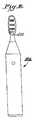
- Figure 18illustrates a tooth cleaning element 308 attached by anchor free tufting, for example. Tooth cleaning element 308 is visible with the distal end 320 at the top. The proximal end 322 is at the bottom and a portion of the proximal end 322 is shown as melted. This melting occurs when a heating element is applied and causes the nylon to fuse to the back side of the membrane 304. Elastomeric backing 325 is also shown. This backing 325 is attached to the backside of the head 300 and aids in sealing the head to prevent toothpaste and debris from collecting on the back side of the tooth cleaning elements.
- the molten nylon associated with each tooth cleaning elementshould be free of contact with molten nylon of other tooth cleaning elements.
- the tooth cleaning elementsare spaced sufficiently apart so as to allow the molten nylon of each tooth cleaning element to be separate or isolated from the molten nylon of other tooth cleaning elements.
- tooth cleaning elements 308a, 308b, 308cmay be spaced a distance "X" between the periphery tooth cleaning elements. This spacing may be between 0.3 mm to 0.5 mm. Nevertheless, other values may be used.
- the edge of the molten nylon regions 310a, 310b, 310cmay be separated from the neighboring molten nylon by a spacing "Y" having a range of values between 0.05 mm to 0.1 mm. Nevertheless, other values may be used. Aspects of the arrangements shown in FIGS. 17 , 19 and 20 can be applied to the arrangements of toothbrushes shown in FIGS. 1-16 .
- a force in the z-directionis generally applied to the tooth cleaning elements after they have been heated and attached to the membrane 304. This force acts to loosen the attachment or detach the nylon at the perimeter of the head 300.
- the applied forceis generally greater than the value of brushing forces during a normal brushing operation.
- a platemay be lowered onto the head 300 via a pneumatic cylinder, mechanical movement, hydraulic cylinder, etc. This plate forces the nylon downward towards the elastomer on the back of the head.
- the plateis generally moved a predetermined distance at a predetermined force to break bonds of the nylon tooth cleaning element field from the perimeter of the head. This operation further enables the tooth cleaning elements to be resiliently flexible during brushing.
- the tooth cleaning elements 308a-c in the form of bristlesare attached to the membrane and move accordingly, creating a random topology and by doing so, improves the cleaning of the teeth.
- the moving bristle strandshave more degrees of motion than other toothbrushes and thus represent a different and unique tooth brushing device.
- the toothbrush and tooth cleaning element arrangement describedenables not only movement of the bristles independently of each other, but also allows movement of the membrane around the tooth during brushing.
- This arrangementprovides of a compound movement of the tooth cleaning elements.
- the membrane 304 and tooth cleaning elements 308may be resiliently flexible when brushing forces are applied. Such flexibility may include rotation of the distal tip of the tooth cleaning element through a 360degree arc, as indicated by arrow 330 in Figure 18 .
- this flexibilitymay include z-axis compression of the membrane 304 and tooth cleaning elements 308, as shown in Figure 18 , to allow tooth cleaning elements to encompass the tooth. This movement facilitates enhanced brushing of the lingual and facial surfaces with the dentifrice retained on the tooth cleaning element.
- z-axis movement of the tooth cleaning elementsfacilitates improved interproximal cleaning as well as cleaning of the crowns of the molars.
- Figure 21illustrates a toothbrush head of a toothbrush according to an embodiment of the invention.
- the head 400 of Figure 21includes a peripheral wall or frame 402.
- the head 400also includes an elastomeric membrane 404 connected to the peripheral frame 402 and provides a foundation to which various tooth cleaning elements may be mounted.
- the head 400includes tooth cleaning elements 408a, 408b, 408c that are connected to the membrane 404 via molten nylon 410.
- the head 400includes a plurality of walls or dams 412.
- the walls 412are elastomeric and are molded into the back of the membrane 404.
- the walls 412are directed downward, toward the back of the head 400 and in a direction opposite the tooth cleaning elements 408.
- a heating elementis applied to the tooth cleaning elements 408a-c and the proximal end of the tooth cleaning elements 408a-c will melt to the back side of the membrane 404.
- the molten nylon 410will spread around the area of the tooth cleaning elements 408a-c.
- the walls 412may be generally spaced a distance D from the center of the cleaning element, as shown in Figure 21 , to isolate the molten nylon of each tooth cleaning element 408a-c and prevent the molten nylon 410 of one tooth cleaning element from fusing with the molten nylon of another tooth cleaning element.
- a single heating elementmay be used to apply high temperature to melt the nylon at a melt flow temperature.
- separate heating elementsmay be used for each tooth cleaning element in order to prevent the wall 412 from coming in contact with the heating element.
- one heating elementmay be used, however, this heating element may include machine areas such that no contact is made with the nylon tooth cleaning elements in designated areas.
- Figure 22is a cross-sectional view of the arrangement of Figure 21 .
- the peripheral frame 402is shown with the membrane 404 attached.
- the wall or dam 412is shown molded into the membrane 404 and extending downward toward the back of the head 400.
- Shown behind the molded wall 412is a tooth cleaning element 408.
- the molten nylon attaching the tooth cleaning element to the head 400is not visible since the wall 412 prevents the molten nylon from flowing around it.
- a backing 420is shown.
- the backingmay comprise an elastomeric material and generally seals the head 400 from the backside (e.g., opposite of the tooth cleaning elements) to prevent dentifrice and debris from collecting on the underside of the tooth cleaning elements.
- Figure 23illustrates another embodiment.
- tooth cleaning elements 508form a generally rectangular shape of a tuft of bristles.
- the walls 512are shown having a slight curvature. This curvature may aid in the shape of the walls 512 following the contour of the dome shaped membrane.
- the walls 512may also be formed in alternate shapes to be tailored to the shapes of the tooth cleaning elements and to further enable movement of the tooth cleaning elements independently of the other tooth cleaning elements.
Landscapes
- Brushes (AREA)
Description
- The present invention relates to toothbrushes.
- The head of a conventional toothbrush usually has a flat or slightly altered surface to which cleaning elements are attached. Usually the cleaning elements are strands of plastic material(s) formed into tufts or other groupings. The strand groupings are attached to the head either before or after forming the toothbrush handle.
- Various attempts have been made for providing flexibility to the manner in which the bristles are attached. Various approaches have also been taken wherein the bristle carrying surface of the head is not flat.
U.S. Patent No. 1,688,581 , for example, discloses a toothbrush having a bristle carrying member which is ordinarily bowed inwardly into the hollow head. The bristle carrying member can be bowed outwardly by manipulating a wire mounted in the toothbrush.US2005/0188487 , on which the respective pre-characterising portions of the independent claims are based, discloses a toothbrush including a head having a dome shaped membrane. - The present invention pertains to a toothbrush having an oral care region attached to a handle. The oral care region has a membrane which provides flexible movement of tooth cleaning elements.
- The aspect of the present invention provides a toothbrush according to claim 1. The membrane may be generally curvilinear shaped and resiliently flexible when a brushing force is applied to the tooth cleaning element.
- In another aspect, the present invention provides a method of manufacturing a toothbrush, the method being as defined in claim 6.
- Preferred embodiments are provided in the dependent claims.
Figure 1 is a perspective view of a toothbrush not according to the invention;Figure 2 is a side elevational view of the toothbrush shown inFigure 1 ;Figure 3 is a front elevational view of the toothbrush shown inFigures 1-2 ;Figure 4 is a cross-sectional view taken throughFigure 3 along the line 4-4;Figure 5 is a front elevational view of a powered toothbrush not according to the invention;Figure 6 is a perspective view of a toothbrush not according to the invention and having elastic areas in the head and handle to allow deflection of the brush, bristles and handle for better teeth cleaning and control;Figure 7 is a side elevational view of the toothbrush shown inFigure 6 ;Figure 8 is a top plan view of the toothbrush shown inFigures 6-7 ;Figure 9 is a side elevational view of the toothbrush ofFigure 6 showing deflection in the open area under the bristles and the handle area;Figure 10 is a top plan view of a powered toothbrush not according to the invention;Figure 11 is a perspective view of a toothbrush not according to the invention;Figure 12 is a side elevational view of the toothbrush shown inFigure 11 ;Figure 13 is a top plan view of the toothbrush shown inFigures 11-12 ;Figure 14 is an end elevational view of the toothbrush shown inFigures 11-13 in its original closed position;Figure 15 is a cross-sectional view taken throughFigure 13 along the line 15-15, but with the brush head in its hinged open position and omitting some of the cleaning elements;Figure 16 is a front elevational view of a powered toothbrush not according to the invention;Figure 17 is a rear view of a toothbrush head of a toothbrush not according to the invention;Figure 18 is a cross-sectional view of a cleaning element of the toothbrush head ofFigure 17 taken along line 18-18;Figure 19 is a rear view of an alternate arrangement of the toothbrush head ofFigure 17 , not according to the invention;Figure 20 is a rear view of the toothbrush head ofFigure 17 schematically illustrating additional features;Figure 21 is a rear view of a toothbrush head of a toothbrush according to an embodiment of the invention;Figure 22 is a cross-sectional view of a barrier wall of the toothbrush head ofFigure 21 ; andFigure 23 is a rear view of an alternate arrangement of the toothbrush head ofFigure 21 , in accordance with another embodiment of the toothbrush of the invention.Figures 1-4 illustrate atoothbrush 10. As shown therein,toothbrush 10 includes a handle 12 and ahead 14. Handle 12 may include asuitable grip pad 16 made of an elastomer material. The focus of this improvement is primarily directed to the structure ofhead 14. As shown inFigure 4 ,head 14 has abase portion 18 with anupstanding wall 20 to create a peripheral frame extending outwardly abovebase portion 18. Amembrane 22 is attached toframe 20 completely along its periphery.Membrane 22 in its initial non-use condition is convex or bowed outwardly as best shown inFigure 4 . The convex bowing is provided both in the longitudinal and transverse directions, thus presenting a dome-likeouter surface 24 to whichcleaning elements 26 are connected.- Cleaning elements in the form of strands or bristles are attached via in-molded technology (IMT) methods. The strands utilizing IMT methods are preferably attached during formation of the toothbrush handle or at least during formation of the head which is the portion of the toothbrush to which the strands and other materials are attached. Referring to
Figures 1-4 andFigure 5 , the use of thin cross-sections of material formembrane 22 so that it is flexible and resilient. The cross-section shown, for example, inFigure 4 is formed like a moon crescent thus representing a shape similar to the dome. - Alternatively, the toothbrush is particularly suitable for cleaning elements in the form of strands or bristles attached via anchor free tufting (AFT). In the AFT toothbrush brush making process, described in detail in
U.S. Patent No. 6,779,851 , nylon is fed into a pre-molded plate that can be made from any thermoplastic or elastomer material or combination thereof. This nylon may be processed into bristle tufts of various sizes and shapes. The non-use or proximal end of the nylon is heated and melted to retain the nylon in the brush head when a reasonable pulling force is applied. This head plate may then be ultrasonically welded to a pre-molded handle that has a peripheral wall or frame on which the head plate will rest and become fused to the handle. - Because of the open space 28 between
base portion 18 andmembrane 22, the membrane displaces from its original dome-like shape to be distorted into other shapes as the cleaning elements orbristles 26 contact the teeth of a user. Thus, thedome 22 has a thin membrane of material or combinations of material that can flex to become altered from its original shape and recover to its original shape randomly during brushing. Thebristles 26 are attached to the flexible dome and move accordingly, creating a random topology and by doing so, improves the cleaning of the teeth. The moving bristle strands have more degrees of motion than other toothbrushes and thus represent a different and unique tooth brushing device. - Referring to
Figure 3 , thehead 14 is generally oval shape and themembrane 22 has a corresponding oval shape. Any suitable form of cleaning elements may be used as thecleaning elements 26. The term "cleaning elements" is intended to be used in a generic sense which could include conventional fiber bristles or massage elements or other forms of cleaning elements such as elastomeric fingers or walls arranged in a circular cross-sectional shape or any type of desired shape including straight portions or sinusoidal portions. Where bristles are used, the bristles could be mounted to tuft blocks or sections by extending through suitable openings in the tuft blocks so that the base of the bristles is mounted within or below the tuft block and belowmembrane 22. - It is to be understood that the specific illustration of the cleaning elements is for exemplary non-limiting purposes. The toothbrush can be provided with various combinations of the same or different cleaning element configurations (such as stapled or in-molded technology bristles, anchor free technology (AFT), etc.) and/or with the same bristle or cleaning element materials (such as nylon bristles, spiral bristles, rubber bristles, etc.). Similarly, while
Figure 2 illustrates the cleaning elements to be generally perpendicular to theouter surface 24membrane 22 orhead 14 some or all of the cleaning elements may be angled at various angles with respect to the outer surface ofhead 14. It is thereby possible to select the combination of cleaning element configurations, materials and orientations to achieve specific intended results to deliver additional oral health benefits, like enhanced cleaning tooth polishing, tooth whitening and/or massaging of the gums. Cleaning elements 26 are IMT bristles. AlthoughFigures 1-3 illustrate themembrane 22 to occupy generally theentire head 14, thehead 14 alternatively may be of sufficient size that it could include other bristle carrying surfaces adjacent to thedome shape membrane 22.- Although
Figures 1-4 illustrate a manually operated toothbrush, the head may instead include one or more power or electrically operated movable sections carrying cleaning elements. Such movable section may oscillate in a rotational manner or may oscillate linearly in a longitudinal direction with respect to the longitudinal axis of the head or may oscillate linearly in a lateral or transverse direction with respect to the longitudinal axis of the head. The movable section may oscillate in and out in a direction toward and away from the outer surface of the head. The movable section may rock back and forth with respect to the outer surface of the head. The movable section may rotate continuously in the same direction, rather than oscillate. Any suitable drive mechanism may be used for imparting the desired motion to the movable section. Where plural movable sections are used, all of the movable sections may have the same type and direction of movement, or combinations of different movements may be used. Figure 5 illustrates a toothbrush 10A which includes a power driven movable disc orsection 30 having cleaning elements. Themovable section 30 could be oscillated rotationally such as by using the type of drive mechanism shown inU.S. Patent No. 5,625,916 , or could move in and out using the type of drive mechanism shown inU.S. Patent No. Re 35,941 . Alternatively, the other types of drives referred to above could movesection 30 in other manners and directions. AlthoughFigure 5 showsmovable section 30 to be at the distal end of the head, the movable section(s) could be located at any desired location on the head.- Handle 12,
base 18 andframe 20 are preferably made of hard plastic materials which are used for manual toothbrushes. As noted, however, a characteristic ofdome shape membrane 22 is that it is made of a flexible resilient material such as an elastomer capable of being moved from its original position and then returning to that original position. Membrane 22 may be secured to frame 20 in any suitable manner. Thus, for example,frame 20 includes inwardly inclined surfaces for receivingmembrane 22. Other structural arrangements may be used to mountmembrane 22 onhead 14.Figures 6-9 illustrate amanual toothbrush 10. This is a variation of the prior construction using a trampoline type structure to achieve an up and down motion. As shown thereintoothbrush 110 includes ahandle 112 and ahead 114. Handle 112 may include asuitable area 116 made of an elastomeric material. This elastomeric portion of the handle is preferably molded with anopen area 118 which is readily deformable by the user. Theelastomeric material 16 on the top side of the handle 12 (as viewed inFigures 6, 7 and 9 ) will yield under pressure of the user's fingers to provide a better grip on the handle while providing a more comfortable feel to the handle.Figure 9 illustrates thiselastomeric portion 116 of thehandle 112 in a depressed state. The downward arrow in this Figure represents the pressure applied by the toothbrush user. Theopen area 118 is thereby minimized. As soon as the user's pressure is released, the properties of theelastomeric portion 116 of thehandle 112 return theelastomeric material 116 to its original shape illustrated inFig. 6 .- A similar flexible, deformable
open area 120 is created in the head by inclusion of anelastomeric portion 122 in the head overlyingopen area 120.Cleaning elements 124 are arrayed in the elastomeric portion of the head and fastened thereto by known methods including in-molded technology (IMT). Bristle attachment utilizing IMT methods generally occurs during formation of the toothbrush handle or at least during formation of theelastomeric portion 122 of thehead 114. - In use, the application of pressure by the toothbrush user causes a like pressure of the teeth against cleaning
elements 124 as illustrated by the arrow inFigure 9 . This causes deflection of theelastomeric portion 122 ofhead 114 which in turn causes a reorientation of cleaning elements relative to the teeth being cleaned. As the user's pressure is reduced, theopen area 120 ofhead 114 opens up causing the cleaning elements to follow the shape of the teeth being brushed and thereby improving the cleaning of the teeth. When all user pressure is released, theopen area 120 returns to its original shape. - The
elastomeric portion 122 ofhead 114 should be a material or combinations of material that can flex to become altered from its original shape and recover to its original shape randomly during brushing. The cleaning elements, for example, bristles, are attached to the flexible membrane creating a flexible orientation of cleaningelements 124 which improves the cleaning of the teeth. The moving bristle strands have considerable degrees of motion and thus provide a unique tooth brushing experience. - Any suitable form of cleaning elements may be used as the
cleaning elements 124, as discussed with the construction ofFigures 1-5 . It is to be understood that the specific illustration of the cleaning elements is merely for exemplary purposes. WhileFigures 7 and 9 illustrates the cleaning elements to be generally perpendicular to theelastomeric portion 122 ofhead 114, some or all of the cleaning elements may be angled at various angles. It is thereby possible to select the combination of cleaning element configurations, materials and orientations to achieve specific intended results to deliver additional oral health benefits, like enhanced cleaning, tooth polishing, tooth whitening and/or massaging of the gums. - Portions of
handle 112 andhead 114, may be made of a rigid plastic material which is used for manual toothbrushes. As noted, however, a feature of this toothbrush is use ofelastomeric portions 116 of the handle and/orelastomeric portion 122 ofhead 114, such as an elastomer capable of being moved from its original position and then returning to its original position. - A construction may also be practiced where the
head 114 includes one or more power or electrically operated movable sections carrying cleaning elements. Figure 10 illustrates atoothbrush 110A which includes a power driven movable disc or section 150 having cleaning elements. The movable section 150 could be similar tosection 30 ofFigure 5 . AlthoughFigure 10 shows movable section 150 to be at the one end of the head, as withFigure 5 , the movable section(s) could be located at any desired location on the head.- In another construction, a toothbrush includes a head longitudinally separated into side by side areas by means of a flexible hinge structure that serves as a spring to return the brush head materials and cleaning areas to their original position.
Figures 11-13 illustrate a toothbrush 210 which includes anelongated handle 212 and ahead 214. A portion ofhandle 212 may be recessed at grippingarea 216 betweenshoulders Shoulder 218 could extend outwardly a sufficient distance to act as a hook or ledge to facilitate hanging the toothbrush in an inverted condition. Head 214 and handle 212 are elongated and have a longitudinal axis. As shown inFigures 14 and 15 ,head 214 includes aspine 222 which extends collinear with the longitudinal axis or major axis of the toothbrush handle and head. As a result,head 214 is separated into two side by sidelongitudinal sections spine 222.Spine 222 is made of a resilient material such as an elastomer which is sufficiently flexible as to be movable and yet return to its original position. As a result,spine 222 functions as a hinge axis whereby the side byside sections Figure 14 to an open position such as shown inFigure 15 when the cleaning elements on thesections sections spine 222. Preferably hinge orspine 222 is confined tohead 214.- As illustrated, each of the
sections elements 228 is located at the outer periphery of eachsection elements 230 is located closer to thespine 222. Preferably, the terminal surfaces 232 of theinner cleaning elements 230 are tapered toward thehinge axis 222 so that the adjacent terminal ends 232 of each inner set of cleaning elements forms an obtuse angle as indicated by the letter A inFigure 14 when the brush head is in its original position. - The outer sets of cleaning
elements 228 extend outwardly a longer distance from the outer surface of the sections than do theinner cleaning elements 230. As a result, the combined cleaning elements are designed to wrap around the edge of the teeth for simultaneous possible contact with both the front and top of the teeth. SeeFigure 14 . During use the brush head is pressed against the edge of the teeth causing the flexible hinge to open and close during cleaning. - As illustrated in
Figures 11-13 , the outer sets of cleaningelements 228 are bristle bundles of plaque bristles. The inner sets of cleaningelements 230 may be bristles formed by in-molded technology (IMT) where sets of bristles are fused together at one end and the fused end is inserted in a mold cavity during the manufacture of the head. Figure 15 shows the sections 224,226 in their open position.Figure 15 omits some of the cleaning elements so as to provide a better understanding of how the cleaning elements are mounted. As shown therein, the plaque bristles 228 are in the form of bristle bundles or tufts inserted intoindividual holes 234 inbristle container 236. The inner sets of cleaningelements 230 are IMT bristles mounted inIMT container 238. TheIMT containers 238 may be made of soft flexible elastomer material integral withhinge axis 222, as shown inFigure 15 .- As shown in
Figures 11-13 thebristle container 236 does not extend completely to the distal end of thehead 214. Accordingly,side plates 240 are provided on each side of the head longitudinally abutting against bristlecontainers 236 and disposed againstcontainers 238 for the remaining length ofcontainers 238 so that a smooth contour results along the side of thehead 214.Side plates 240 may also be made of a soft, flexible elastomer material. - As best shown in
Figures 11-12 each inner row of IMT bristles 230 has its bristles spaced apart or staggered so that the inclined IMT bristles of each section may fit between the spacing of adjacent IMT bristles of the other section. - Although
Figures 11-15 illustrate a preferred form of cleaning elements to be the plaque bristles and IMT bristles, any suitable form of cleaning elements may be used as thecleaning elements - Similarly, it is to be understood that the specific illustration of the cleaning elements is for exemplary non-limiting purposes. An embodiment can be practiced with various combinations of the same or different cleaning element configurations (such as stapled or IMT bristles, AFT, etc.) and/or with the same bristle or cleaning element materials (such as nylon bristles, spiral bristles, rubber bristles, etc.) Similarly, while
Figure 12 illustrates the cleaning elements to be generally perpendicular to the outer surface ofhead 214 some or all of the cleaning elements may be angled at various angles with respect to the outer surface ofhead 214. It is thereby possible to select the combination of cleaning element configurations, materials and orientations to achieve specific intended results to deliver additional oral health benefits, like enhanced cleaning tooth polishing, tooth whitening and/or massaging of the gums. - Handle 212 could be made of a conventional hard plastic material which could, however, include a
soft elastomer section 242 near thehead 214. Bristle containers 236,236 could also be made of a hard plastic material whileside plates 240 andIMT containers 238 are made of a soft elastomer material. By having the bristlecontainers 236 mounted against theIMT containers 238, thebristle containers 236 and theircleaning elements 228 move along with the movement of theIMT containers 238 in response to the IMT bristles 230 contacting the teeth. If desired, thebristle containers 236 may also be made of a soft elastomer material. - Although
Figures 11-13 illustrate a manually operated toothbrush, the head may instead include one or more power or electrically operated movable sections carrying cleaning elements.Figure 6 illustrates a toothbrush 210 which includes a power driven movable disc orsection 250 having cleaning elements, similar to the movable sections oftoothbrushes 10A and 110A. Figure 17 illustrates a toothbrush head according to yet another arrangement. The head comprises an oral care region for having elements for brushing teeth or tissue in the mouth. It should be noted that, although the toothbrush head shown inFigure 17 is generally used with a manual toothbrush, the head and method of manufacturing the head, may also be used with a toothbrush that includes one or more power or electrically operated moveable sections carrying cleaning elements.Figure 17 illustrates atoothbrush head 300 having a peripheral wall or frame 302 as previously described with respect toFIG. 4 . Thetoothbrush head 300 also includes anelastomeric membrane 304 that is connected to theperipheral frame 302 and provides a foundation to which various tooth cleaning elements may be mounted or otherwise attached. In addition, thehead 300 includes tooth cleaning elements 308 mounted to thehead 300 via themembrane 304. The term "cleaning elements" is intended to be used in a generic sense which could include conventional fiber bristles or massage elements or other forms of cleaning elements such as elastomeric fingers or walls arranged in a circular cross-sectional shape or any type of desired shape including straight portions or sinusoidal portions.- In the arrangement shown in
Figure 17 , the tooth cleaning elements are mounted using Anchor Free Tufting (AFT) as described above. The tooth cleaning elements, such as bristle tufts or elastomeric members, are depicted as round in theFIG. 17 . Nevertheless, tooth cleaning elements having alternate shapes may also be used. For example, shapes such as square, rectangular, etc., may be used, as shown inFigure 19 . During the AFT process, the tooth cleaning elements provides in a nylon material are heated and the proximal end of thetooth cleaning elements tooth cleaning elements 308a-c to themembrane 304. A schematic representation of themolten nylon 310 is shown inFigure 17 andFigure 19 . InFigure 19 ,toothbrush 350 includestooth cleaning elements Figure 18 illustrates a tooth cleaning element 308 attached by anchor free tufting, for example. Tooth cleaning element 308 is visible with thedistal end 320 at the top. Theproximal end 322 is at the bottom and a portion of theproximal end 322 is shown as melted. This melting occurs when a heating element is applied and causes the nylon to fuse to the back side of themembrane 304.Elastomeric backing 325 is also shown. Thisbacking 325 is attached to the backside of thehead 300 and aids in sealing the head to prevent toothpaste and debris from collecting on the back side of the tooth cleaning elements.- To enable the tooth cleaning elements to move independently of each other, the molten nylon associated with each tooth cleaning element should be free of contact with molten nylon of other tooth cleaning elements. In the arrangement of
Figures 17 ,19 and20 the tooth cleaning elements are spaced sufficiently apart so as to allow the molten nylon of each tooth cleaning element to be separate or isolated from the molten nylon of other tooth cleaning elements. For instance, inFigure 20 ,tooth cleaning elements FIGS. 17 ,19 and20 can be applied to the arrangements of toothbrushes shown inFIGS. 1-16 . - To further enable movement of the tooth cleaning elements 308, a force in the z-direction is generally applied to the tooth cleaning elements after they have been heated and attached to the
membrane 304. This force acts to loosen the attachment or detach the nylon at the perimeter of thehead 300. The applied force is generally greater than the value of brushing forces during a normal brushing operation. In order to overcome this attachment, a plate may be lowered onto thehead 300 via a pneumatic cylinder, mechanical movement, hydraulic cylinder, etc. This plate forces the nylon downward towards the elastomer on the back of the head. The plate is generally moved a predetermined distance at a predetermined force to break bonds of the nylon tooth cleaning element field from the perimeter of the head. This operation further enables the tooth cleaning elements to be resiliently flexible during brushing. Thus, thetooth cleaning elements 308a-c in the form of bristles are attached to the membrane and move accordingly, creating a random topology and by doing so, improves the cleaning of the teeth. The moving bristle strands have more degrees of motion than other toothbrushes and thus represent a different and unique tooth brushing device. - The toothbrush and tooth cleaning element arrangement described enables not only movement of the bristles independently of each other, but also allows movement of the membrane around the tooth during brushing. This arrangement provides of a compound movement of the tooth cleaning elements. For instance, the
membrane 304 and tooth cleaning elements 308 may be resiliently flexible when brushing forces are applied. Such flexibility may include rotation of the distal tip of the tooth cleaning element through a 360degree arc, as indicated byarrow 330 inFigure 18 . In addition, this flexibility may include z-axis compression of themembrane 304 and tooth cleaning elements 308, as shown inFigure 18 , to allow tooth cleaning elements to encompass the tooth. This movement facilitates enhanced brushing of the lingual and facial surfaces with the dentifrice retained on the tooth cleaning element. In addition, z-axis movement of the tooth cleaning elements facilitates improved interproximal cleaning as well as cleaning of the crowns of the molars. Figure 21 illustrates a toothbrush head of a toothbrush according to an embodiment of the invention. Thehead 400 ofFigure 21 includes a peripheral wall orframe 402. Thehead 400 also includes anelastomeric membrane 404 connected to theperipheral frame 402 and provides a foundation to which various tooth cleaning elements may be mounted. In addition, thehead 400 includestooth cleaning elements membrane 404 viamolten nylon 410.- In the arrangement of
Figure 21 , thehead 400 includes a plurality of walls ordams 412. In one arrangement, thewalls 412 are elastomeric and are molded into the back of themembrane 404. Thewalls 412 are directed downward, toward the back of thehead 400 and in a direction opposite thetooth cleaning elements 408. To attach or mount the tooth cleaning elements by way of anchor free tufting, a heating element is applied to thetooth cleaning elements 408a-c and the proximal end of thetooth cleaning elements 408a-c will melt to the back side of themembrane 404. Themolten nylon 410 will spread around the area of thetooth cleaning elements 408a-c. Thewalls 412 may be generally spaced a distance D from the center of the cleaning element, as shown inFigure 21 , to isolate the molten nylon of eachtooth cleaning element 408a-c and prevent themolten nylon 410 of one tooth cleaning element from fusing with the molten nylon of another tooth cleaning element. - In the arrangement of
Figure 21 , a single heating element may be used to apply high temperature to melt the nylon at a melt flow temperature. In an alternate arrangement, separate heating elements may be used for each tooth cleaning element in order to prevent thewall 412 from coming in contact with the
heating element. In yet another arrangement, one heating element may be used, however, this heating element may include machine areas such that no contact is made with the nylon tooth cleaning elements in designated areas. Figure 22 is a cross-sectional view of the arrangement ofFigure 21 . Theperipheral frame 402 is shown with themembrane 404 attached. In addition, the wall ordam 412 is shown molded into themembrane 404 and extending downward toward the back of thehead 400. Shown behind the moldedwall 412 is atooth cleaning element 408. The molten nylon attaching the tooth cleaning element to thehead 400 is not visible since thewall 412 prevents the molten nylon from flowing around it. In addition, abacking 420 is shown. The backing may comprise an elastomeric material and generally seals thehead 400 from the backside (e.g., opposite of the tooth cleaning elements) to prevent dentifrice and debris from collecting on the underside of the tooth cleaning elements.Figure 23 illustrates another embodiment. As shown, tooth cleaning elements 508 form a generally rectangular shape of a tuft of bristles. Thewalls 512 are shown having a slight curvature. This curvature may aid in the shape of thewalls 512 following the contour of the dome shaped membrane. Thewalls 512 may also be formed in alternate shapes to be tailored to the shapes of the tooth cleaning elements and to further enable movement of the tooth cleaning elements independently of the other tooth cleaning elements.- The embodiment described in which walls or dams are used to prevent molten nylon associated with each tooth cleaning element from fusing with molten nylon associated with another cleaning element enables the cleaning elements to move independently of each other.
- The specific features and acts described above are disclosed as example forms of implementing the claims. Numerous other embodiments, modifications and variations within the scope of the appended claims will occur to persons of ordinary skill in the art from a review of this disclosure.
Claims (9)
- A toothbrush, comprising:a handle;an oral care region secured to the handle and the oral care region further including:an upstanding wall to create a peripheral frame (402, 502);a membrane (404, 504) connected to the peripheral frame (402, 502); anda plurality of tooth cleaning elements (408a, 408b, 408c, 508a, 508b, 508c) connected to the membrane (404, 504) such that the tooth cleaning elements (408a, 408b, 408c, 508a, 508b, 508c) move independently of each other, wherein the tooth cleaning elements (408a, 408b, 408c, 508a, 508b, 508c) are attached to the membrane (404, 504) individually;characterized in that the membrane (404, 504) has at least one wall (412, 512) extending downwardly from an underside thereof between adjacent tooth cleaning elements (408a, 408b, 408c, 508a, 508b, 508c).
- The toothbrush of claim 1, wherein at least one of the plurality of tooth cleaning elements (408a, 408b, 408c, 508a, 508b, 508c) comprises a tuft of bristles.
- The toothbrush of claim 1, wherein the at least one wall (412, 512) of the membrane (404, 504) is arcuate shaped.
- The toothbrush of claim 1, wherein the membrane (404, 504) has a convex shape.
- The toothbrush of claim 4, wherein the membrane (404, 504) is resiliently flexible when a brushing force is applied thereto.
- A method of manufacturing a toothbrush, comprising:connecting a membrane (404, 504) to a peripheral frame (402, 502) of a head (400, 500) of the toothbrush;providing a plurality of tooth cleaning elements (408a, 408b, 408c, 508a, 508b, 508c) on the membrane (404, 504); andheating a proximal portion of the plurality of tooth cleaning elements (408a,
408b, 408c, 508a, 508b, 508c) such that the proximal portion melts to attach each of the plurality of tooth cleaning elements (408a, 408b, 408c, 508a, 508b, 508c) to the membrane (404, 504);characterized by providing at least one wall (412, 512) to the membrane (404, 504); andby the step of providing the plurality of tooth cleaning elements (408a, 408b, 408c, 508a, 508b, 508c) comprising providing the at least one wall (412, 512) between the plurality of tooth cleaning elements (408a, 408b, 408c, 508a, 508b, 508c);wherein the melted portion of the tooth cleaning elements (408a, 408b, 408c, 508a, 508b, 508c) is isolated from the melted portion of other tooth cleaning elements (408a, 408b, 408c, 508a, 508b, 508c) by the at least one wall (412, 512). - The method of manufacturing a toothbrush of claim 6, wherein the step of providing of the at least one wall (412, 512) includes molding the at least one wall (412, 512) into the head (400, 500) of the toothbrush.
- The method of manufacturing a toothbrush of claim 6, wherein the step of connecting the membrane (404, 504) includes connecting the membrane (404, 504) such that it is substantially dome shaped.
- The method of manufacturing a toothbrush of claim 6, wherein the step of connecting the membrane (404, 504) further includes connecting the membrane (404, 504) such that it is resiliently flexible when a brushing force is applied.
Applications Claiming Priority (2)
| Application Number | Priority Date | Filing Date | Title |
|---|---|---|---|
| US11/611,726US8695148B2 (en) | 2002-08-09 | 2006-12-15 | Toothbrush |
| PCT/US2007/087141WO2008073950A1 (en) | 2006-12-15 | 2007-12-12 | Toothbrush |
Publications (2)
| Publication Number | Publication Date |
|---|---|
| EP2120637A1 EP2120637A1 (en) | 2009-11-25 |
| EP2120637B1true EP2120637B1 (en) | 2019-05-08 |
Family
ID=39126383
Family Applications (1)
| Application Number | Title | Priority Date | Filing Date |
|---|---|---|---|
| EP07855074.6ANot-in-forceEP2120637B1 (en) | 2006-12-15 | 2007-12-12 | Toothbrush |
Country Status (12)
| Country | Link |
|---|---|
| US (3) | US8695148B2 (en) |
| EP (1) | EP2120637B1 (en) |
| KR (1) | KR101169503B1 (en) |
| CN (1) | CN101610696B (en) |
| AU (1) | AU2007333137B2 (en) |
| BR (1) | BRPI0721121A2 (en) |
| CA (1) | CA2672740C (en) |
| MX (1) | MX2009006394A (en) |
| MY (1) | MY160427A (en) |
| RU (1) | RU2430667C2 (en) |
| TW (1) | TWI357315B (en) |
| WO (1) | WO2008073950A1 (en) |
Families Citing this family (23)
| Publication number | Priority date | Publication date | Assignee | Title |
|---|---|---|---|---|
| US8042217B2 (en)* | 2004-11-02 | 2011-10-25 | Colgate-Palmolive Company | Toothbrush and method of making the same |
| BRPI0806941B1 (en) | 2007-02-02 | 2018-12-18 | Gillette Co | oral care implement |
| USD654695S1 (en) | 2009-12-18 | 2012-02-28 | Colgate-Palmolive Company | Toothbrush |
| USD654270S1 (en) | 2009-12-18 | 2012-02-21 | Colgate-Palmolive Company | Toothbrush handle |
| US8863345B2 (en)* | 2009-12-18 | 2014-10-21 | Colgate-Palmolive Company | Oral care implement having a closed-loop arrangement of cleaning elements |
| USD675830S1 (en)* | 2009-12-18 | 2013-02-12 | Colgate-Palmolive Company | Toothbrush |
| USD654696S1 (en) | 2009-12-18 | 2012-02-28 | Colgate-Palmolive Company | Toothbrush handle with tissue cleaner |
| AU2010366254B2 (en) | 2010-12-21 | 2015-01-29 | Colgate-Palmolive Company | Oral care implement |
| CA2822139C (en) | 2010-12-21 | 2016-06-21 | Colgate-Palmolive Company | Oral care implement having a flexible head |
| USD689286S1 (en)* | 2011-05-02 | 2013-09-10 | Colgate-Palmolive Company | Toothbrush |
| EP2769009B1 (en)* | 2011-10-17 | 2016-12-21 | DSM IP Assets B.V. | Brush containing mono-filaments containing polyamide-410 |
| DE102011122106A1 (en)* | 2011-12-22 | 2013-06-27 | Carl Freudenberg Kg | Broom block with bristle structure |
| RU2592772C2 (en) | 2012-03-09 | 2016-07-27 | Колгейт-Палмолив Компани | Method of making head plate and formation of oral care device using said method |
| KR20140145603A (en) | 2012-03-22 | 2014-12-23 | 콜게이트-파아므올리브캄파니 | Oral care implement having flexible handle |
| US9456680B2 (en)* | 2013-09-18 | 2016-10-04 | Dr. Fresh, Llc | Toothbrush with angled bristles |
| RU2639974C1 (en)* | 2013-12-05 | 2017-12-25 | Колгейт-Палмолив Компани | Oral care appliance with cap |
| KR20160071184A (en) | 2014-12-11 | 2016-06-21 | 이경민 | Toothbrushes for children |
| US9750588B1 (en)* | 2015-10-20 | 2017-09-05 | Michael Harmoush | Toothbrush |
| US20170156483A1 (en)* | 2015-11-17 | 2017-06-08 | Changsuk Seo | Toothbrush with Elastic Bristles |
| KR101695177B1 (en) | 2016-08-12 | 2017-01-11 | 민호영 | Toothbrush handles enabling to adjust angle and length |
| CN109464684A (en)* | 2017-09-07 | 2019-03-15 | 高露洁-棕榄公司 | Oral care implement disinfection system |
| US10646028B1 (en) | 2019-03-12 | 2020-05-12 | Nathan Quang Huynh | Brush assemblies |
| USD919301S1 (en)* | 2020-07-06 | 2021-05-18 | Thumbs Up Innovations Technology Co., Ltd. | Brush head |
Family Cites Families (69)
| Publication number | Priority date | Publication date | Assignee | Title |
|---|---|---|---|---|
| US301644A (en)* | 1884-07-08 | thompson | ||
| US1058273A (en)* | 1910-07-30 | 1913-04-08 | Luxury Sales Company | Massage device. |
| US1128139A (en)* | 1913-10-31 | 1915-02-09 | John P Hoffman | Tooth-brush. |
| US1191556A (en)* | 1915-08-31 | 1916-07-18 | Philip W Blake | Tooth-brush. |
| US1500939A (en)* | 1923-03-20 | 1924-07-08 | David A Howell | Egg-crate unpacking and repacking apparatus |
| US1588785A (en)* | 1924-06-30 | 1926-06-15 | Robert H Van Sant | Toothbrush |
| US1616484A (en)* | 1926-10-06 | 1927-02-08 | Daniel J Beynon | Toothbrush |
| US1688581A (en)* | 1927-09-09 | 1928-10-23 | Glassman Nathan | Toothbrush |
| US1924152A (en)* | 1931-11-02 | 1933-08-29 | David M Coney | Toothbrush |
| US1928328A (en)* | 1931-11-25 | 1933-09-26 | Erik Dempster Lindegren | Toothbrush |
| US2003243A (en)* | 1933-07-29 | 1935-05-28 | Ann Watson | Toothbrush |
| US2148483A (en)* | 1936-05-20 | 1939-02-28 | Lomo Gum Massager Co | Tooth and gum massager and exerciser |
| US2176309A (en)* | 1937-06-09 | 1939-10-17 | Lomo Gum Massager Company | Gum massager |
| US2676350A (en)* | 1953-03-16 | 1954-04-27 | Stanley Home Products Inc | Toothbrush with a flexible head |
| US2706825A (en)* | 1954-04-02 | 1955-04-26 | Amoron R Blakeman | Toothbrush |
| GB989953A (en)* | 1960-09-13 | 1965-04-22 | Bernard Cyzer | Improvements in or relating to toothbrushes |
| FR2115659A5 (en)* | 1970-11-27 | 1972-07-07 | Celluloid Sa | |
| US3739419A (en)* | 1970-12-07 | 1973-06-19 | Stance Ind Inc | Non-snagging hairbrush |
| US4240452A (en)* | 1979-09-13 | 1980-12-23 | Jean San Bau | Elastic base toothbrush |
| US4520526A (en)* | 1984-06-22 | 1985-06-04 | Peters Charles W | Resiliently flexible toothbrush |
| US5228466A (en)* | 1988-01-19 | 1993-07-20 | Klinkhammer Ronald W | Toothbrush |
| DE68925271T2 (en)* | 1988-10-27 | 1996-08-14 | Texas Instruments Inc | Communication, information, maintenance diagnostics and training system |
| US5146645A (en)* | 1991-03-01 | 1992-09-15 | The Procter & Gamble Company | Toothbrush employing resiliently buckling arch to indicate excessive brushing pressure |
| CZ282998B6 (en)* | 1991-03-27 | 1997-12-17 | Lingner And Fischer Gmbh | Toothbrush |
| GB9106511D0 (en)* | 1991-03-27 | 1991-05-15 | Lingner & Fischer Gmbh | Novel article |
| EP0567672B1 (en)* | 1992-04-28 | 1995-09-06 | G.B. Boucherie, N.V. | A method of producing toothbrushes |
| GB9211338D0 (en)* | 1992-05-28 | 1992-07-15 | Ausworld Consultants Limited | Toothbrush |
| RU2026626C1 (en) | 1992-06-02 | 1995-01-20 | Игорь Серафимович Иванов | Tooth brush |
| US5259083A (en)* | 1992-09-24 | 1993-11-09 | 1008335 Ontario Inc. | Mechanical toothbrush |
| US5355546A (en)* | 1992-12-11 | 1994-10-18 | Scheier Paul A | Toothbrush with resilient flexible bristle support |
| US5325560A (en)* | 1993-01-08 | 1994-07-05 | Pavone Bernadino J | Orthodontic toothbrush |
| US5454133A (en)* | 1993-11-02 | 1995-10-03 | Garnet; Arrow | Toothbrush |
| US5481775A (en)* | 1994-03-22 | 1996-01-09 | Chesebrough-Pond's Usa Co., Division Of Conopco, Inc. | Toothbrush with movable head |
| US6219874B1 (en)* | 1994-07-13 | 2001-04-24 | The Procter & Gamble Co. | Resiliently flexible bristle bearing head toothbrush |
| US5524312A (en)* | 1995-03-06 | 1996-06-11 | Tan; Kuo-Ching | Electric toothbrush |
| US5625916A (en)* | 1995-05-24 | 1997-05-06 | Mcdougall; Greg | Toothbrush |
| US5581840A (en)* | 1995-12-13 | 1996-12-10 | Chen; Li-Min | Hairbrush |
| US5630244A (en)* | 1996-01-02 | 1997-05-20 | Chang; Ching-Min | Elastic toothbrush |
| US6408476B1 (en)* | 1996-01-18 | 2002-06-25 | The Procter & Gamble Company | Toothbrush with elastomer filled flexible head |
| US5946759A (en)* | 1996-01-18 | 1999-09-07 | The Procter & Gamble Company | Brush head |
| GB9606900D0 (en)* | 1996-04-02 | 1996-06-05 | Unilever Plc | Toothbrush |
| US6185779B1 (en)* | 1996-08-22 | 2001-02-13 | Smithkline Beecham Consumer Healthcare Gmbh | Toothbrush comprising a flexibly linked region in the head |
| US5839149A (en)* | 1996-08-26 | 1998-11-24 | Scheier; Paul A. | Toothbrush with resilient flexible bristle support |
| GB9620092D0 (en)* | 1996-09-26 | 1996-11-13 | Unilever Plc | A brush and method for producing same |
| DE19743556A1 (en)* | 1997-10-01 | 1999-04-08 | Schiffer Fa M & C | Method and device for producing a toothbrush |
| USD421843S (en)* | 1998-05-18 | 2000-03-28 | Pi-Design Ag | Toothbrush |
| US6000083A (en)* | 1998-09-30 | 1999-12-14 | Dr. Johns Products, Ltd. | Electric toothbrush |
| KR20000047379A (en) | 1998-12-31 | 2000-07-25 | 박경식 | a tooth brush |
| USD428260S (en)* | 1999-01-04 | 2000-07-18 | Harada Stephen D | Anterior lingual toothbrush |
| USD430401S (en)* | 1999-01-04 | 2000-09-05 | Harada Stephen D | Set of bristles for a toothbrush |
| US6088870A (en)* | 1999-02-10 | 2000-07-18 | Colgate-Palmolive Company | Toothbrush head with flexibly mounted bristles |
| US20050015907A1 (en)* | 1999-04-22 | 2005-01-27 | Glaxosmithkline Consumer Healthcare Gmbh & Co. Kg | Toothbrush |
| US6571417B1 (en)* | 1999-06-11 | 2003-06-03 | James Albert Gavney, Jr. | Dentition cleaning device and system |
| AU141876S (en)* | 1999-07-06 | 2000-09-21 | Unilever Plc | Toothbrush |
| DE19932377A1 (en)* | 1999-07-13 | 2001-02-08 | Coronet Werke Gmbh | Method and device for the production of brushes and brushes produced thereafter |
| DE19937481A1 (en)* | 1999-08-07 | 2001-02-08 | Coronet Werke Gmbh | Brushes, especially toothbrushes |
| DE19949671A1 (en) | 1999-10-14 | 2001-04-19 | Coronet Werke Gmbh | Brush, especially toothbrush |
| USD431366S (en)* | 2000-03-31 | 2000-10-03 | Harada Stephen D | Toothbrush |
| DE20006311U1 (en)* | 2000-04-06 | 2001-08-09 | G.B. Boucherie N.V., Izegem | Device for attaching tufts of bristles to brush bodies |
| USD459084S1 (en)* | 2000-12-21 | 2002-06-25 | Stephen D. Harada | Toothbrush head with stepped bristle array |
| US20030033679A1 (en)* | 2001-08-17 | 2003-02-20 | Joseph Fattori | Brush section for an electric toothbrush |
| US6938294B2 (en)* | 2002-07-17 | 2005-09-06 | Colgate-Palmolive Company | Toothbrush with movable head sections for enhanced oral care |
| US7757326B2 (en)* | 2003-10-30 | 2010-07-20 | Cologate-Palmolive Company | Toothbrush with enhanced cleaning effects |
| ES2444545T3 (en)* | 2002-08-09 | 2014-02-25 | Colgate-Palmolive Company | Toothbrush |
| RU2328195C2 (en)* | 2002-08-09 | 2008-07-10 | Колгейт-Палмолив Компани | Flexible toothbrush and technique to manufacture it |
| US7360270B2 (en)* | 2002-08-09 | 2008-04-22 | Colgate-Palmolive Company | Toothbrush |
| EP1538946A2 (en)* | 2002-08-19 | 2005-06-15 | Colgate-Palmolive Company | Toothbrush |
| DE10259723A1 (en)* | 2002-12-19 | 2004-07-01 | Trisa Holding Ag | Toothbrush and process for making it |
| CN1993066B (en) | 2004-08-03 | 2010-07-21 | 荷兰联合利华有限公司 | Toothbrush |
- 2006
- 2006-12-15USUS11/611,726patent/US8695148B2/ennot_activeExpired - Fee Related
- 2007
- 2007-12-12CACA2672740Apatent/CA2672740C/ennot_activeExpired - Fee Related
- 2007-12-12BRBRPI0721121-0A2Apatent/BRPI0721121A2/ennot_activeApplication Discontinuation
- 2007-12-12KRKR1020097014764Apatent/KR101169503B1/ennot_activeExpired - Fee Related
- 2007-12-12RURU2009127091/12Apatent/RU2430667C2/ennot_activeIP Right Cessation
- 2007-12-12AUAU2007333137Apatent/AU2007333137B2/ennot_activeCeased
- 2007-12-12WOPCT/US2007/087141patent/WO2008073950A1/enactiveApplication Filing
- 2007-12-12CNCN2007800514431Apatent/CN101610696B/ennot_activeExpired - Fee Related
- 2007-12-12MYMYPI20092501Apatent/MY160427A/enunknown
- 2007-12-12MXMX2009006394Apatent/MX2009006394A/enactiveIP Right Grant
- 2007-12-12EPEP07855074.6Apatent/EP2120637B1/ennot_activeNot-in-force
- 2007-12-14TWTW096147793Apatent/TWI357315B/ennot_activeIP Right Cessation
- 2014
- 2014-04-15USUS14/252,911patent/US9038229B2/ennot_activeExpired - Lifetime
- 2015
- 2015-04-06USUS14/679,289patent/US10194735B2/ennot_activeExpired - Lifetime
Non-Patent Citations (1)
| Title |
|---|
| None* |
Also Published As
| Publication number | Publication date |
|---|---|
| KR20090089911A (en) | 2009-08-24 |
| AU2007333137B2 (en) | 2012-04-05 |
| US20170332773A9 (en) | 2017-11-23 |
| RU2009127091A (en) | 2011-01-20 |
| TW200911165A (en) | 2009-03-16 |
| RU2430667C2 (en) | 2011-10-10 |
| US10194735B2 (en) | 2019-02-05 |
| MY160427A (en) | 2017-03-15 |
| US20070204417A1 (en) | 2007-09-06 |
| TWI357315B (en) | 2012-02-01 |
| WO2008073950A1 (en) | 2008-06-19 |
| CA2672740C (en) | 2012-07-10 |
| CN101610696A (en) | 2009-12-23 |
| US9038229B2 (en) | 2015-05-26 |
| MX2009006394A (en) | 2009-08-26 |
| EP2120637A1 (en) | 2009-11-25 |
| BRPI0721121A2 (en) | 2014-03-04 |
| US20150208797A1 (en) | 2015-07-30 |
| US20140223683A1 (en) | 2014-08-14 |
| CN101610696B (en) | 2013-03-13 |
| US8695148B2 (en) | 2014-04-15 |
| CA2672740A1 (en) | 2008-06-19 |
| KR101169503B1 (en) | 2012-07-27 |
| AU2007333137A1 (en) | 2008-06-19 |
Similar Documents
| Publication | Publication Date | Title |
|---|---|---|
| EP2120637B1 (en) | Toothbrush | |
| US7360270B2 (en) | Toothbrush | |
| EP2117378B1 (en) | Oral care implement | |
| AU2010257380B2 (en) | Flexible dome toothbrush | |
| CZ298597A3 (en) | Toothbrush | |
| AU2010241214A1 (en) | Toothbrush | |
| US8990996B2 (en) | Toothbrush | |
| HK1085631B (en) | Toothbrush |
Legal Events
| Date | Code | Title | Description |
|---|---|---|---|
| PUAI | Public reference made under article 153(3) epc to a published international application that has entered the european phase | Free format text:ORIGINAL CODE: 0009012 | |
| 17P | Request for examination filed | Effective date:20090626 | |
| AK | Designated contracting states | Kind code of ref document:A1 Designated state(s):AT BE BG CH CY CZ DE DK EE ES FI FR GB GR HU IE IS IT LI LT LU LV MC MT NL PL PT RO SE SI SK TR | |
| DAX | Request for extension of the european patent (deleted) | ||
| REG | Reference to a national code | Ref country code:HK Ref legal event code:DE Ref document number:1136475 Country of ref document:HK | |
| 17Q | First examination report despatched | Effective date:20130307 | |
| RAP1 | Party data changed (applicant data changed or rights of an application transferred) | Owner name:COLGATE-PALMOLIVE COMPANY | |
| REG | Reference to a national code | Ref country code:HK Ref legal event code:WD Ref document number:1136475 Country of ref document:HK | |
| STAA | Information on the status of an ep patent application or granted ep patent | Free format text:STATUS: EXAMINATION IS IN PROGRESS | |
| GRAP | Despatch of communication of intention to grant a patent | Free format text:ORIGINAL CODE: EPIDOSNIGR1 | |
| STAA | Information on the status of an ep patent application or granted ep patent | Free format text:STATUS: GRANT OF PATENT IS INTENDED | |
| INTG | Intention to grant announced | Effective date:20181130 | |
| GRAS | Grant fee paid | Free format text:ORIGINAL CODE: EPIDOSNIGR3 | |
| GRAA | (expected) grant | Free format text:ORIGINAL CODE: 0009210 | |
| STAA | Information on the status of an ep patent application or granted ep patent | Free format text:STATUS: THE PATENT HAS BEEN GRANTED | |
| RIN1 | Information on inventor provided before grant (corrected) | Inventor name:MOSKOVICH, ROBERT A. Inventor name:RUSSELL, BRUCE M. Inventor name:WAGUESPACK, KENNETH Inventor name:ROONEY, MICHAEL CHARLES | |
| AK | Designated contracting states | Kind code of ref document:B1 Designated state(s):AT BE BG CH CY CZ DE DK EE ES FI FR GB GR HU IE IS IT LI LT LU LV MC MT NL PL PT RO SE SI SK TR | |
| REG | Reference to a national code | Ref country code:GB Ref legal event code:FG4D | |
| REG | Reference to a national code | Ref country code:CH Ref legal event code:EP Ref country code:AT Ref legal event code:REF Ref document number:1128817 Country of ref document:AT Kind code of ref document:T Effective date:20190515 | |
| REG | Reference to a national code | Ref country code:DE Ref legal event code:R096 Ref document number:602007058337 Country of ref document:DE Ref country code:IE Ref legal event code:FG4D | |
| REG | Reference to a national code | Ref country code:CH Ref legal event code:NV Representative=s name:NOVAGRAAF INTERNATIONAL SA, CH | |
| REG | Reference to a national code | Ref country code:NL Ref legal event code:MP Effective date:20190508 | |
| REG | Reference to a national code | Ref country code:LT Ref legal event code:MG4D | |
| PG25 | Lapsed in a contracting state [announced via postgrant information from national office to epo] | Ref country code:NL Free format text:LAPSE BECAUSE OF FAILURE TO SUBMIT A TRANSLATION OF THE DESCRIPTION OR TO PAY THE FEE WITHIN THE PRESCRIBED TIME-LIMIT Effective date:20190508 Ref country code:LT Free format text:LAPSE BECAUSE OF FAILURE TO SUBMIT A TRANSLATION OF THE DESCRIPTION OR TO PAY THE FEE WITHIN THE PRESCRIBED TIME-LIMIT Effective date:20190508 Ref country code:SE Free format text:LAPSE BECAUSE OF FAILURE TO SUBMIT A TRANSLATION OF THE DESCRIPTION OR TO PAY THE FEE WITHIN THE PRESCRIBED TIME-LIMIT Effective date:20190508 Ref country code:PT Free format text:LAPSE BECAUSE OF FAILURE TO SUBMIT A TRANSLATION OF THE DESCRIPTION OR TO PAY THE FEE WITHIN THE PRESCRIBED TIME-LIMIT Effective date:20190908 Ref country code:ES Free format text:LAPSE BECAUSE OF FAILURE TO SUBMIT A TRANSLATION OF THE DESCRIPTION OR TO PAY THE FEE WITHIN THE PRESCRIBED TIME-LIMIT Effective date:20190508 Ref country code:FI Free format text:LAPSE BECAUSE OF FAILURE TO SUBMIT A TRANSLATION OF THE DESCRIPTION OR TO PAY THE FEE WITHIN THE PRESCRIBED TIME-LIMIT Effective date:20190508 | |
| PG25 | Lapsed in a contracting state [announced via postgrant information from national office to epo] | Ref country code:GR Free format text:LAPSE BECAUSE OF FAILURE TO SUBMIT A TRANSLATION OF THE DESCRIPTION OR TO PAY THE FEE WITHIN THE PRESCRIBED TIME-LIMIT Effective date:20190809 Ref country code:BG Free format text:LAPSE BECAUSE OF FAILURE TO SUBMIT A TRANSLATION OF THE DESCRIPTION OR TO PAY THE FEE WITHIN THE PRESCRIBED TIME-LIMIT Effective date:20190808 Ref country code:LV Free format text:LAPSE BECAUSE OF FAILURE TO SUBMIT A TRANSLATION OF THE DESCRIPTION OR TO PAY THE FEE WITHIN THE PRESCRIBED TIME-LIMIT Effective date:20190508 | |
| REG | Reference to a national code | Ref country code:AT Ref legal event code:MK05 Ref document number:1128817 Country of ref document:AT Kind code of ref document:T Effective date:20190508 | |
| PG25 | Lapsed in a contracting state [announced via postgrant information from national office to epo] | Ref country code:EE Free format text:LAPSE BECAUSE OF FAILURE TO SUBMIT A TRANSLATION OF THE DESCRIPTION OR TO PAY THE FEE WITHIN THE PRESCRIBED TIME-LIMIT Effective date:20190508 Ref country code:AT Free format text:LAPSE BECAUSE OF FAILURE TO SUBMIT A TRANSLATION OF THE DESCRIPTION OR TO PAY THE FEE WITHIN THE PRESCRIBED TIME-LIMIT Effective date:20190508 Ref country code:DK Free format text:LAPSE BECAUSE OF FAILURE TO SUBMIT A TRANSLATION OF THE DESCRIPTION OR TO PAY THE FEE WITHIN THE PRESCRIBED TIME-LIMIT Effective date:20190508 Ref country code:SK Free format text:LAPSE BECAUSE OF FAILURE TO SUBMIT A TRANSLATION OF THE DESCRIPTION OR TO PAY THE FEE WITHIN THE PRESCRIBED TIME-LIMIT Effective date:20190508 Ref country code:CZ Free format text:LAPSE BECAUSE OF FAILURE TO SUBMIT A TRANSLATION OF THE DESCRIPTION OR TO PAY THE FEE WITHIN THE PRESCRIBED TIME-LIMIT Effective date:20190508 Ref country code:RO Free format text:LAPSE BECAUSE OF FAILURE TO SUBMIT A TRANSLATION OF THE DESCRIPTION OR TO PAY THE FEE WITHIN THE PRESCRIBED TIME-LIMIT Effective date:20190508 | |
| REG | Reference to a national code | Ref country code:DE Ref legal event code:R097 Ref document number:602007058337 Country of ref document:DE | |
| PG25 | Lapsed in a contracting state [announced via postgrant information from national office to epo] | Ref country code:IT Free format text:LAPSE BECAUSE OF FAILURE TO SUBMIT A TRANSLATION OF THE DESCRIPTION OR TO PAY THE FEE WITHIN THE PRESCRIBED TIME-LIMIT Effective date:20190508 | |
| PLBE | No opposition filed within time limit | Free format text:ORIGINAL CODE: 0009261 | |
| STAA | Information on the status of an ep patent application or granted ep patent | Free format text:STATUS: NO OPPOSITION FILED WITHIN TIME LIMIT | |
| PG25 | Lapsed in a contracting state [announced via postgrant information from national office to epo] | Ref country code:TR Free format text:LAPSE BECAUSE OF FAILURE TO SUBMIT A TRANSLATION OF THE DESCRIPTION OR TO PAY THE FEE WITHIN THE PRESCRIBED TIME-LIMIT Effective date:20190508 | |
| 26N | No opposition filed | Effective date:20200211 | |
| PG25 | Lapsed in a contracting state [announced via postgrant information from national office to epo] | Ref country code:PL Free format text:LAPSE BECAUSE OF FAILURE TO SUBMIT A TRANSLATION OF THE DESCRIPTION OR TO PAY THE FEE WITHIN THE PRESCRIBED TIME-LIMIT Effective date:20190508 | |
| PG25 | Lapsed in a contracting state [announced via postgrant information from national office to epo] | Ref country code:SI Free format text:LAPSE BECAUSE OF FAILURE TO SUBMIT A TRANSLATION OF THE DESCRIPTION OR TO PAY THE FEE WITHIN THE PRESCRIBED TIME-LIMIT Effective date:20190508 | |
| REG | Reference to a national code | Ref country code:BE Ref legal event code:MM Effective date:20191231 | |
| PG25 | Lapsed in a contracting state [announced via postgrant information from national office to epo] | Ref country code:MC Free format text:LAPSE BECAUSE OF FAILURE TO SUBMIT A TRANSLATION OF THE DESCRIPTION OR TO PAY THE FEE WITHIN THE PRESCRIBED TIME-LIMIT Effective date:20190508 | |
| PG25 | Lapsed in a contracting state [announced via postgrant information from national office to epo] | Ref country code:IE Free format text:LAPSE BECAUSE OF NON-PAYMENT OF DUE FEES Effective date:20191212 Ref country code:LU Free format text:LAPSE BECAUSE OF NON-PAYMENT OF DUE FEES Effective date:20191212 | |
| PG25 | Lapsed in a contracting state [announced via postgrant information from national office to epo] | Ref country code:BE Free format text:LAPSE BECAUSE OF NON-PAYMENT OF DUE FEES Effective date:20191231 | |
| PGFP | Annual fee paid to national office [announced via postgrant information from national office to epo] | Ref country code:GB Payment date:20201228 Year of fee payment:14 Ref country code:FR Payment date:20201227 Year of fee payment:14 | |
| PGFP | Annual fee paid to national office [announced via postgrant information from national office to epo] | Ref country code:CH Payment date:20210106 Year of fee payment:14 | |
| PG25 | Lapsed in a contracting state [announced via postgrant information from national office to epo] | Ref country code:CY Free format text:LAPSE BECAUSE OF FAILURE TO SUBMIT A TRANSLATION OF THE DESCRIPTION OR TO PAY THE FEE WITHIN THE PRESCRIBED TIME-LIMIT Effective date:20190508 | |
| PGFP | Annual fee paid to national office [announced via postgrant information from national office to epo] | Ref country code:DE Payment date:20201229 Year of fee payment:14 | |
| PG25 | Lapsed in a contracting state [announced via postgrant information from national office to epo] | Ref country code:IS Free format text:LAPSE BECAUSE OF FAILURE TO SUBMIT A TRANSLATION OF THE DESCRIPTION OR TO PAY THE FEE WITHIN THE PRESCRIBED TIME-LIMIT Effective date:20190908 | |
| PG25 | Lapsed in a contracting state [announced via postgrant information from national office to epo] | Ref country code:HU Free format text:LAPSE BECAUSE OF FAILURE TO SUBMIT A TRANSLATION OF THE DESCRIPTION OR TO PAY THE FEE WITHIN THE PRESCRIBED TIME-LIMIT; INVALID AB INITIO Effective date:20071212 Ref country code:MT Free format text:LAPSE BECAUSE OF FAILURE TO SUBMIT A TRANSLATION OF THE DESCRIPTION OR TO PAY THE FEE WITHIN THE PRESCRIBED TIME-LIMIT Effective date:20190508 | |
| REG | Reference to a national code | Ref country code:DE Ref legal event code:R119 Ref document number:602007058337 Country of ref document:DE | |
| REG | Reference to a national code | Ref country code:CH Ref legal event code:PL | |
| GBPC | Gb: european patent ceased through non-payment of renewal fee | Effective date:20211212 | |
| PG25 | Lapsed in a contracting state [announced via postgrant information from national office to epo] | Ref country code:GB Free format text:LAPSE BECAUSE OF NON-PAYMENT OF DUE FEES Effective date:20211212 Ref country code:DE Free format text:LAPSE BECAUSE OF NON-PAYMENT OF DUE FEES Effective date:20220701 | |
| PG25 | Lapsed in a contracting state [announced via postgrant information from national office to epo] | Ref country code:FR Free format text:LAPSE BECAUSE OF NON-PAYMENT OF DUE FEES Effective date:20211231 | |
| PG25 | Lapsed in a contracting state [announced via postgrant information from national office to epo] | Ref country code:LI Free format text:LAPSE BECAUSE OF NON-PAYMENT OF DUE FEES Effective date:20211231 Ref country code:CH Free format text:LAPSE BECAUSE OF NON-PAYMENT OF DUE FEES Effective date:20211231 |