EP2116183A1 - Robust opto-electrical ear located cardiovascular monitoring device - Google Patents
Robust opto-electrical ear located cardiovascular monitoring deviceDownload PDFInfo
- Publication number
- EP2116183A1 EP2116183A1EP08155801AEP08155801AEP2116183A1EP 2116183 A1EP2116183 A1EP 2116183A1EP 08155801 AEP08155801 AEP 08155801AEP 08155801 AEP08155801 AEP 08155801AEP 2116183 A1EP2116183 A1EP 2116183A1
- Authority
- EP
- European Patent Office
- Prior art keywords
- signal
- sensor
- monitoring device
- reliability
- cardiovascular monitoring
- Prior art date
- Legal status (The legal status is an assumption and is not a legal conclusion. Google has not performed a legal analysis and makes no representation as to the accuracy of the status listed.)
- Granted
Links
- 230000002526effect on cardiovascular systemEffects0.000titleclaimsabstractdescription116
- 238000012806monitoring deviceMethods0.000titleclaimsabstractdescription37
- 238000013186photoplethysmographyMethods0.000claimsabstractdescription47
- 238000000034methodMethods0.000claimsabstractdescription35
- 238000012545processingMethods0.000claimsabstractdescription33
- 238000002489impedance cardiographyMethods0.000claimsabstractdescription24
- 238000002565electrocardiographyMethods0.000claimsabstract5
- 230000033001locomotionEffects0.000claimsdescription42
- 230000003287optical effectEffects0.000claimsdescription38
- 230000005855radiationEffects0.000claimsdescription15
- 210000000883ear externalAnatomy0.000claimsdescription9
- 230000002123temporal effectEffects0.000claimsdescription5
- 238000012935AveragingMethods0.000claimsdescription3
- 230000035945sensitivityEffects0.000claimsdescription2
- 238000003672processing methodMethods0.000claims8
- 230000002708enhancing effectEffects0.000claims1
- 238000004458analytical methodMethods0.000description12
- 238000005259measurementMethods0.000description12
- 210000001519tissueAnatomy0.000description8
- 239000008280bloodSubstances0.000description7
- 210000004369bloodAnatomy0.000description7
- 230000017531blood circulationEffects0.000description7
- 210000001367arteryAnatomy0.000description6
- 230000000694effectsEffects0.000description6
- 230000010412perfusionEffects0.000description6
- 239000006261foam materialSubstances0.000description5
- 238000002847impedance measurementMethods0.000description4
- 230000001788irregularEffects0.000description4
- 210000000707wristAnatomy0.000description4
- 210000000624ear auricleAnatomy0.000description3
- 230000006870functionEffects0.000description3
- 238000012544monitoring processMethods0.000description3
- 230000000541pulsatile effectEffects0.000description3
- 239000000523sampleSubstances0.000description3
- 210000001994temporal arteryAnatomy0.000description3
- 206010058558HypoperfusionDiseases0.000description2
- 230000001133accelerationEffects0.000description2
- 230000004872arterial blood pressureEffects0.000description2
- QVGXLLKOCUKJST-UHFFFAOYSA-Natomic oxygenChemical compound[O]QVGXLLKOCUKJST-UHFFFAOYSA-N0.000description2
- 230000005540biological transmissionEffects0.000description2
- 238000004364calculation methodMethods0.000description2
- 210000005069earsAnatomy0.000description2
- 238000001914filtrationMethods0.000description2
- 239000012530fluidSubstances0.000description2
- 210000003128headAnatomy0.000description2
- 238000002496oximetryMethods0.000description2
- 229910052760oxygenInorganic materials0.000description2
- 239000001301oxygenSubstances0.000description2
- 238000002106pulse oximetryMethods0.000description2
- 230000035485pulse pressureEffects0.000description2
- 206010002091AnaesthesiaDiseases0.000description1
- 206010047139VasoconstrictionDiseases0.000description1
- 206010047141VasodilatationDiseases0.000description1
- 238000010521absorption reactionMethods0.000description1
- 230000003044adaptive effectEffects0.000description1
- 230000001464adherent effectEffects0.000description1
- 238000001949anaesthesiaMethods0.000description1
- 230000037005anaesthesiaEffects0.000description1
- 238000013459approachMethods0.000description1
- 230000008081blood perfusionEffects0.000description1
- 210000000845cartilageAnatomy0.000description1
- 230000001413cellular effectEffects0.000description1
- 238000006243chemical reactionMethods0.000description1
- 230000004087circulationEffects0.000description1
- 238000004590computer programMethods0.000description1
- 230000003750conditioning effectEffects0.000description1
- 238000012937correctionMethods0.000description1
- 230000001419dependent effectEffects0.000description1
- 239000003792electrolyteSubstances0.000description1
- 230000005670electromagnetic radiationEffects0.000description1
- 238000005516engineering processMethods0.000description1
- 210000003414extremityAnatomy0.000description1
- 239000006260foamSubstances0.000description1
- 238000009532heart rate measurementMethods0.000description1
- 239000004973liquid crystal related substanceSubstances0.000description1
- 239000000463materialSubstances0.000description1
- 230000000737periodic effectEffects0.000description1
- 230000002093peripheral effectEffects0.000description1
- 230000010363phase shiftEffects0.000description1
- 230000037081physical activityEffects0.000description1
- 238000012805post-processingMethods0.000description1
- 230000010349pulsationEffects0.000description1
- 230000000284resting effectEffects0.000description1
- 230000000717retained effectEffects0.000description1
- 230000001020rhythmical effectEffects0.000description1
- 238000007493shaping processMethods0.000description1
- 230000035939shockEffects0.000description1
- 230000005236sound signalEffects0.000description1
- 230000003595spectral effectEffects0.000description1
- 230000001960triggered effectEffects0.000description1
- 230000025033vasoconstrictionEffects0.000description1
- 230000024883vasodilationEffects0.000description1
- 210000003462veinAnatomy0.000description1
- 230000002747voluntary effectEffects0.000description1
Images


Classifications
- A—HUMAN NECESSITIES
- A61—MEDICAL OR VETERINARY SCIENCE; HYGIENE
- A61B—DIAGNOSIS; SURGERY; IDENTIFICATION
- A61B5/00—Measuring for diagnostic purposes; Identification of persons
- A61B5/02—Detecting, measuring or recording for evaluating the cardiovascular system, e.g. pulse, heart rate, blood pressure or blood flow
- A61B5/024—Measuring pulse rate or heart rate
- A61B5/02416—Measuring pulse rate or heart rate using photoplethysmograph signals, e.g. generated by infrared radiation
- A—HUMAN NECESSITIES
- A61—MEDICAL OR VETERINARY SCIENCE; HYGIENE
- A61B—DIAGNOSIS; SURGERY; IDENTIFICATION
- A61B5/00—Measuring for diagnostic purposes; Identification of persons
- A61B5/02—Detecting, measuring or recording for evaluating the cardiovascular system, e.g. pulse, heart rate, blood pressure or blood flow
- A61B5/024—Measuring pulse rate or heart rate
- A61B5/0245—Measuring pulse rate or heart rate by using sensing means generating electric signals, i.e. ECG signals
- A—HUMAN NECESSITIES
- A61—MEDICAL OR VETERINARY SCIENCE; HYGIENE
- A61B—DIAGNOSIS; SURGERY; IDENTIFICATION
- A61B5/00—Measuring for diagnostic purposes; Identification of persons
- A61B5/68—Arrangements of detecting, measuring or recording means, e.g. sensors, in relation to patient
- A61B5/6801—Arrangements of detecting, measuring or recording means, e.g. sensors, in relation to patient specially adapted to be attached to or worn on the body surface
- A61B5/6813—Specially adapted to be attached to a specific body part
- A61B5/6814—Head
- A61B5/6815—Ear
- A61B5/6816—Ear lobe
- A—HUMAN NECESSITIES
- A61—MEDICAL OR VETERINARY SCIENCE; HYGIENE
- A61B—DIAGNOSIS; SURGERY; IDENTIFICATION
- A61B5/00—Measuring for diagnostic purposes; Identification of persons
- A61B5/68—Arrangements of detecting, measuring or recording means, e.g. sensors, in relation to patient
- A61B5/6887—Arrangements of detecting, measuring or recording means, e.g. sensors, in relation to patient mounted on external non-worn devices, e.g. non-medical devices
- A—HUMAN NECESSITIES
- A61—MEDICAL OR VETERINARY SCIENCE; HYGIENE
- A61B—DIAGNOSIS; SURGERY; IDENTIFICATION
- A61B5/00—Measuring for diagnostic purposes; Identification of persons
- A61B5/72—Signal processing specially adapted for physiological signals or for diagnostic purposes
- A61B5/7203—Signal processing specially adapted for physiological signals or for diagnostic purposes for noise prevention, reduction or removal
- A61B5/7207—Signal processing specially adapted for physiological signals or for diagnostic purposes for noise prevention, reduction or removal of noise induced by motion artifacts
- A61B5/721—Signal processing specially adapted for physiological signals or for diagnostic purposes for noise prevention, reduction or removal of noise induced by motion artifacts using a separate sensor to detect motion or using motion information derived from signals other than the physiological signal to be measured
- A—HUMAN NECESSITIES
- A61—MEDICAL OR VETERINARY SCIENCE; HYGIENE
- A61B—DIAGNOSIS; SURGERY; IDENTIFICATION
- A61B5/00—Measuring for diagnostic purposes; Identification of persons
- A61B5/02—Detecting, measuring or recording for evaluating the cardiovascular system, e.g. pulse, heart rate, blood pressure or blood flow
- A61B5/024—Measuring pulse rate or heart rate
- A61B5/0245—Measuring pulse rate or heart rate by using sensing means generating electric signals, i.e. ECG signals
- A61B5/02455—Measuring pulse rate or heart rate by using sensing means generating electric signals, i.e. ECG signals provided with high/low alarm devices
- A—HUMAN NECESSITIES
- A61—MEDICAL OR VETERINARY SCIENCE; HYGIENE
- A61B—DIAGNOSIS; SURGERY; IDENTIFICATION
- A61B5/00—Measuring for diagnostic purposes; Identification of persons
- A61B5/103—Measuring devices for testing the shape, pattern, colour, size or movement of the body or parts thereof, for diagnostic purposes
- A61B5/11—Measuring movement of the entire body or parts thereof, e.g. head or hand tremor or mobility of a limb
- A—HUMAN NECESSITIES
- A61—MEDICAL OR VETERINARY SCIENCE; HYGIENE
- A61B—DIAGNOSIS; SURGERY; IDENTIFICATION
- A61B5/00—Measuring for diagnostic purposes; Identification of persons
- A61B5/72—Signal processing specially adapted for physiological signals or for diagnostic purposes
- A61B5/7235—Details of waveform analysis
- A61B5/7253—Details of waveform analysis characterised by using transforms
- A61B5/726—Details of waveform analysis characterised by using transforms using Wavelet transforms
Definitions
- the present inventionrelates to a portable cardiovascular monitoring device providing a heart rate estimation with improved robustness and reliability.
- Portable cardiovascular monitoring devicesare classically composed of a processing device and an external probe such as electronic stethoscope, optical measure at ear lobe, chest belt for electrocardiogram (ECG) based measurement, etc.
- ECGelectrocardiogram
- the use of an external probeis often considered as a reduction of the user's comfort.
- ECG-based pulse rate detecting devices using external electrode probesare for instance disclosed in documents US4108166 , US6018677 , US 6149602 and WO0051680 .
- PPGphotoplethysmography
- the PPG measurement systemclassically consists of a source of radiant optical energy and at least one detector for detecting the intensity of the radiant optical energy after propagation through the human body tissue. Infra-red light is predominantly used since it is relatively well absorbed in blood and weakly absorbed in body tissue. Since light is highly scattered in tissue, a detector positioned on the surface of the skin can measure reflections (or transmissions) from a range of depths. Any change in blood volume induced, for example, by the periodic cardiovascular pulse wave can be measured with a reasonable contrast by the changing optical absorption of radiant optical energy the blood volume induces. This effect will be averaged over many arteries and veins.
- Data processing meanscan then be used for extracting bodily parameters such as heart rate or oxygen concentration in the blood.
- bodily parameterssuch as heart rate or oxygen concentration in the blood.
- the principal advantage of PPG measurementresides in the fact that it is entirely non-invasive and can be applied to any blood bearing tissue, typically a finger, ear lobe, nose and, in some instances, wrist.
- PPGhas widely been used for measuring arterial oxygen saturation known as pulse oximetry.
- PPG-based oximetry sensing devices employing sensors which are typically in contact with the user's finger or nailare for instance disclosed in documents US5237994 , US5645060 , US5662106 , US5934277 , US6018673 , W09952420 , W09962399 and W00125802 .
- PPG-based oximetry and heart rate estimating devices intended to be worn on or around other parts of the human body such as the wrist or ear,are also known, for instance from documents US5807267 and W09714357 .
- PPG measurementsconcern the reliability of the measured PPG sensor signals in conditions of reduced blood flow and/or weak pulse pressure wave, namely low perfusion.
- PPG systemsare commonly worn on the body extremities such as fingers and ears, where low blood flow and/or weak pulse pressure wave conditions can result from hypoperfusion, due for example, to a subject being exposed to cold temperature or at rest. These conditions result in a PPG signal that has almost no discernible arterial blood pressure wave and cannot be practically exploited.
- the operational range of PPG-based cardiovascular monitoring devicesis therefore limited to conditions with sufficient blood flow and/or perfusion that yield a reliable PPG signal.
- a usermay be exposed to cold weather, for example, when practicing during windy conditions and/or cold temperatures.
- the activity intensitymay vary from a resting period with insufficient perfusion due to temperature related vasoconstriction to a high intensity exercise with increased peripheral perfusion due to exercise related vasodilatation. Consequently, there is a need to extend the operational range of cardiovascular monitoring in conditions where the PPG measurements are affected by a reduced blood flow or/and low perfusion.
- An object of the inventionis therefore to propose a new system and method which overcomes at least some limitations of the prior art.
- a portable cardiovascular monitoring devicecomprising a first cardiovascular (CV) sensor based on a PPG technique for providing a first heart rate estimation of a user and at least a second CV sensor based on an ECG or an impedance cardiography (ICG) method for providing a second heart rate estimation.
- the portable cardiovascular monitoring devicecomprises a control device and a signal processing module for estimating the reliability of the first and at least second heart rate estimations. An estimation of a single robust user's heart rate is then obtained by combining the different heart rate estimations according to their reliability indicators or by selecting the heart rate estimations having the highest reliability indicator.
- the CV sensorsare placed in one or two ear-located devices worn in on or the two user's ears.
- the reliability determination of the heart rate estimationsis based on one or more characteristics of CV signals and/or heart rate estimations such as the signal amplitude or signal-to-noise ratio and the variability of the estimated heart rates.
- the different characteristicscan be merged through a fuzzy logic method or a threshold level method.
- the reliability determination of the heart rate estimationis based on the most likely temporal position of each heart rate pulses in CV signals received from the different CV sensors.
- the reliability determinationis based on characteristics of the signal generated by the motion sensor comprised in the ear located device.
- the unreliable CV sensor signalsare switched off.
- the present inventionallows the extension of the operational range of cardiovascular monitoring in conditions, more particularly in conditions of reduced blood flow or/and low perfusion.
- the portable cardiovascular monitoring device of the inventioncan be used for the heart rate monitoring of a user in the context of fitness, outdoors, sport or entertainment activities and is power consumption efficient, thereby increasing the life of a battery in the cardiovascular monitoring device.
- Fig. 1shows a first embodiment of portable cardiovascular monitoring device according to the invention.
- the devicecomprises a first ear located device 1 with a generally circular casing 2 adapted to be placed inside or against the external ear (auricle) of a user in front of the external auditory meatus opening, the side of the casing 2 that can be seen in Fig. 1 facing toward the latter opening.
- the casing 2 of the first ear located device 1contains a sound transducer symbolized by the dashed line circle 3.
- the casing 2is fastened to a hook 4 whose free end part is adapted to hang behind the external ear of a user, as is usual for earphones used with off-the-shelf walkmans, MP players, or ipod, etc.
- the first ear located device 1is equipped with a first PPG-based CV sensor.
- an optical emitter 5is placed in the hook 4 so that it directs radiation toward the casing 2.
- the emitter 5is placed on the non visible side of the hook 4.
- the emitter 5comprises one or more sources of optical radiation, preferably two infrared light emitting devices (LEDs) emitting at one or more different wavelengths. In the present configuration, these sources irradiate a portion of the cartilage of the external ear.
- An optical radiation receiver 6is disposed in the casing 2 so that it can pick up the portion of the optical radiation emitted by the emitter 5 that has passed through the thickness of the external ear.
- the receiver 6comprises a plurality of optical detectors, preferably two pairs of photodiodes (not shown), whose sensitivity ranges are adjusted to the respective wavelengths of the sources. Consequently, the received radiation is a function of variations in the optical characteristics of the portion of the external ear through which the radiation has passed, which variations are caused in particular by variations in the circulation of blood in the external ear.
- the variations in the electrical signal delivered by the receiver 6are therefore representative in particular of the pulsation of the blood and therefore of the heart rate.
- the above configuration where the optical emitter 5 is placed in the casing 2 and the optical radiation receiver 6 placed in the hook 4is also possible.
- the optical emitter 5 and the optical radiation receiver 6can be placed along the hook 4, on the side which is in contact with the user's skin, for example, in a region in vicinity with the posterior auricular artery.
- the receiver 6comprises a pair light detectors disposed on each side of the emitter, formed by one light source, at a determined distance from the light source of the emitter 5, for example, about 10 mm.
- Other possible arrangements of the emitter 5 and receiver 6can comprise one or several light sources and light detectors respectively. In this configuration, light from the optical emitter 5 propagates through the posterior auricular artery and is reflected towards the optical radiation receiver 6.
- the casing 2comprises a part that penetrates inside the external auditory meatus or that has the shape of an earplug.
- the optical receiver 6is placed in the casing 2 on the side which is in contact with the external auditory meatus.
- the optical emitter 5can be placed in the hook 4, on the side which is in contact with the user's skin, for example, in a region in vicinity with the superficial temporal artery. In this configuration, the light emitted from the optical emitter 5 is transmitted across the temporal artery to reach the optical radiation receiver 6.
- the casing 2can be covered with a foam material 7 (only part of which is shown) to protect the portion of the ear surrounding the external auditory meatus opening.
- the foammay be made of a material with flexible and adherent surface.
- the electrical signals delivered by the receiver 6, called in the remaining text PPG-based CV sensor signals,are transferred to a signal acquisition module 12.
- the acquired signal outputted from the acquisition module 12is transferred to a control device 13, more particularly to a signal processing module 14 through a cable 15.
- the acquisition module 12 and signal processing module 14are described in more details below.
- the control device 13can be a media player such as the digital Apple iPod media player or any other handheld computing device such as a cellular telephone, personal digital assistant or other devices having an operating system.
- the signal processing module 14can be installed to the existing media player or handheld computing device or, alternatively, the processor of the media player or handheld computing device can be used for the sensor signal processing.
- Other portable devicesincluding compact disk (CD) or versatile disks (DVD) players, radio receiver, etc., may also be used as well as a control device dedicated to the sole sensing purpose.
- the portable cardiovascular monitoring devicealso comprises a second ECG-based CV sensor for measuring the user's heart rate.
- the measurement of an ECG waveformtypically involves the placement of at least two signal electrodes and a ground electrode widely spaced across the patient's body.
- the first ear located device 1comprises a first ECG signal electrode 8 placed in the hook 4, for example in proximity of the optical emitter 5.
- a second ECG signal electrodecan be placed on the hook of a second ear located device (not shown) worn on the user's other ear or against another body part. Both signal electrodes are placed in a way to be in contact with the user's skin.
- a ground electrode(not shown) is preferably placed far from the ECG signal electrode, for example, in contact with the skin of the user's wrist or arm.
- the ground electrodecan be located on the back of the control device 13 or armband tissue, in contact with the user's skin.
- the ground electrodecan also be placed in any convenient location in the hook 4 or in the casing 2.
- a measuring configurationmay use no ground electrode but only the first and second ECG signal electrodes, placed on the first and second ear located device, respectively. Both first and second ECG signal electrodes may also be located in the first or second ear located device.
- the two ECG signal electrodes and the ground electrodesare typically metallic electrodes.
- the electrodescan be galvanized at the surface of the foam material 7.
- the foam materialmay be embedded with electrolyte properties so as to be substantially conductive.
- the ECG electrodescan be connected to a comparator (not shown) for determining a difference value between the measured electric potentials at the different electrode locations.
- the second CV sensor of the portable cardiovascular monitoring deviceis based on an impedance cardiography (ICG) method.
- ICGimpedance cardiography
- An impedance measurement of a patientis typically made by passing a current between two active impedance electrodes and measuring the resulting potential difference between two passive impedance electrodes.
- the measured impedancedepends on the electrical conductivity of the tissue and fluid through which the current passes.
- the pulse of the bloodstreamcontributes to a pulsatile change in the amount and type of fluid in the current path, which is detected as a pulsatile change in the measured impedance.
- the measurement of pulsatile characteristicsmay be measured using a set of closely spaced sensors on a single housing attached to the user as it is done in an impedance plethysmography measurement (IPG) method.
- IPGimpedance plethysmography measurement
- Impedance measurementsare typically made using a system of at least four electrodes, with the pair of active impedance electrodes being actively driven with a signal generator and the pair of passive impedance electrodes passively receiving a signal related to the active signal and the impedance of the patient.
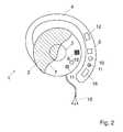
- Fig. 2illustrates an embodiment of the invention, where the first ear located device 1 comprises a pair of active impedance electrodes 10, where one of the active electrodes is disposed on the hook 4 and the other is placed on the casing 2, both electrodes being in contact with the user's skin, so that a current passes between the two active electrodes 10 through the thickness of the external ear.
- a potential difference arising due to the current passing between the two active electrodes 10is measured between two passive impedance electrodes 11, also placed in contact with the user's skin, on the hook 4 and on the casing 2, respectively.
- Other arrangements of the active impedance electrodesare also possible.
- one of the two active electrodes 10can be placed on the first ear located device 1 and the other on the second ear located device, on the hook and/or on the casing 2 respectively.
- This latter arrangementresults in a more robust CV sensor signal due to the greater bloodstream in the current path.
- An example of this type of impedance measurement configurationis described in patent US5178154 , titled “Impedance Cardiograph and Method of Operation Utilizing Peak Aligned Ensemble Averaging".
- the impedance measurementcan be made in substantially the same physical location as optical measurement as shown in figure 2 or can also be made at any other suitable location.
- the pairs of active and passive impedance electrodescan also be aligned at the surface of the hook or of the casing 2, for example, galvanized at the surface of the foam material, in contact with the user's skin.
- the optical and/or electrical CV sensorscan be placed on a branch extending from the ear cushion in the neck area, in the vicinity of an artery (carotide).
- the portable cardiovascular monitoring devicecan be placed in a hearing aid system such as behind-the-ear, in-the-ear, in-the-canal, etc., hearing aid types.
- the portable cardiovascular monitoring deviceuses small earphones, placed outside the external auditory meatus such as the distinctive white earphones that are included with many portable music players, or placed inside the external auditory meatus, such as canalphones.
- the optical emitter 5 and the optical radiation receiver 6are placed on the surface of one of the earphones and the light emitted by the optical emitter 5 propagates through the tissue in the vicinity of the external auditory meatus and is reflected towards the optical radiation receiver 6.
- each earphonemay contain one ECG signal electrode with the ground ECG electrode being placed on one of the earphone.
- the two pairs of active and passive impedance electrodes 10, 11can be arranged equidistant in one of the earphone.
- the optical and electrical CV sensorsare placed in a headband fitted to the head of a user.
- the PPG and ICG-based CV sensorsare placed at locations in the vicinity of a superficial artery such as, for example, the superficial temporal artery in the temporal region or the supraorbital or zygomatico-orbital artery in the front head area.
- the ECG signal electrodescan be placed at opposite locations.
- the cardiovascular monitoring devicecan be fitted to an eyeglass, the optical and ICG-based CV sensors being placed on the eyeglass frame, for example, in the temple and/or nose regions while the ECG signal electrodes can be placed on each eyeglass branch.
- a display unit using liquid crystal or the likecan be placed in front of the eyeglass in order to display information related to, for example, heart rate to the user.
- the optical and electrical CV sensorscan be placed in a clip which is pinched to an earlobe or a portion of an ear, one clip on each ear being necessary for the ECG measurements.
- the signal acquisition module 12comprising, for example, an analog to digital (A/D) converter and signal filtering and shaping means.
- A/Danalog to digital
- the signal processing module 14can be an adequately programmed digital signal processor or DSP or a general purpose microcontroller that also controls the control device 13 or a software module installed and executed by a processor.
- the cable 15can be connected to the control device 13 through a USB connector or any other type of connector.
- the first and second ear located devicescan be powered via the cable 15 by a battery (not shown) contained in the control device 13.
- a digital signal processor or DSPcan be used in conjunction with signal filtration, A/D conversion, and other signal conditioning/processing within the module to extract useful heart rate information from the measured CV sensor signals.
- the functionalities of the signal acquisition module and signal processing modulecan be performed by using one or more application-specific integrated circuits (ASICs).
- the signal processing module 14may be housed within the ear located device 1, for example, within the hook 4. This configuration allows the wireless transmission of the sensor signals, for example, between the ear located device 1 and the control device 13. In the case of ECG and/ICG signals requiring a galvanic connection, only the processed signal can be the wirelessly transmitted. In the above configuration, the ear located device 1 can be powered with a battery (not shown) contained, for example, in the hook 4.
- the ear located device 1possibly also comprises a motion sensor 16 for measuring acceleration along three axes, for example, placed in the hook 4 as shown in Fig.1 , but also possibly placed in the casing (2).
- the motion sensor 16is preferably a MEMS-based three dimensional accelerometer as described in patent US7018338 . It will however be appreciated that other types of accelerometers or motion detecting devices can be used provided they deliver a reliable measure of motion.
- the motion sensor 16could be a gyro-sensor of any suitable technology incorporating a one or multi-dimensional accelerometer, or a rotating or vibrating element.
- the control device 10may further comprise an output device 20 for outputting an indication of the detected pulse rate in the form of an optical, audible signal, or other sensorial signal.
- Such meanscould be a LED, a display, a buzzer, a vibrating device or any other suitable device adapted for transmitting information representative of the pulse rate measurement to the user.
- the outputted signalcan also be superimposed on the sound signals produced by the media player and make it audible to the user through the sound transducer 3 of the ear located device 1.
- the outputted signalmay also comprise an alarm signal when the estimated heart rate value reaches a determined threshold, which could be either a low or high threshold or both.
- FIG. 3A schematic of the portable cardiovascular monitoring device of the invention is shown in Fig. 3 .
- the ear located device 1represented by the dashed line comprises the PPG, ECG and ICG-based CV sensors schematically shown by the numerals 17, 18 and 19 respectively, the signal acquisition module 12 and the motion sensor 16.
- the control device 13is also represented comprising the signal processing device 14, output device 20 and the memory 21 that is described below. Signals from the acquisition module 12 and motion sensor 16 are transferred to the signal processing module 14 through the cable 15.
- the acquired signal originating from the PPG, ECG and/or ICG - based CV sensorsare enhanced using the signal processing module 14 and possibly the motion reference signal provided by the motion sensor 16, in order to correct the acquired signals for movement artifacts.
- the signal enhancementis performed using a method described in PCT application PCT/EP2007/063469 by the present applicant.
- the enhancementcould also be performed exploiting the information contained in the motion reference signal.
- the methodassumes that under rhythmical movements, artifacts on the acquired signal appear as harmonics of the movement frequency.
- the methodcomprises the two steps below.
- the fundamental movement frequencyis extracted from the motion reference signal through one of the following technique: zero-crossing, parametric or non-parametric spectral estimation, autocorrelation, recurrence plots.
- the fundamental movement frequency extracted in the first stepis used to enhance the acquired signal.
- a multiple notch filtercan be employed to attenuate harmonics of movement contributions in the acquired signal.
- non-parametric enhancementcan be used where the movement contribution is cancelled, for example, by putting high resolution restricted discrete Fourier transform estimations at zero from nearest lower minimum to nearest upper minimum at each harmonic of movement frequency.
- the enhancementmay also be performed by a subband approach. This may considerably increase the robustness of the subsequent heart rate estimation.
- the acquired signalis filtered by typically three to four adjacent subband filters with a bandwidth of the fundamental movement frequency and located on harmonics of the movement frequency.
- Each subband filteris designed in such a way that the lower and upper corner frequency correspond to zeros of the given filter (as obtained for Tchebycheff class 2 filters or elliptic filters).
- the heart rate estimationmay then be performed on each subband separately and the most reliable of all bands according to the reliability indexes may be retained.
- the enhanced signalsare further assessed for their reliability in order to select the most appropriate signal or merge the different reliable PPG, ECG and/or ICG CV signals and discard the unreliable signals.
- the reliability of the CV signalswill depend on the measurement conditions such as reduced blood flow or/and low perfusion.
- the reliability analysiscan be based on the characteristics of CV signals and/ or associated heart rate estimations such as: the signal amplitude, pulse frequency, pulse frequency variations, and/or signal-to-noise ratio. Indeed, a signal having a too low pulse amplitude and/or a pulse frequency that is not plausible, i.e., too low, too high or too irregular, etc., may be determined as unreliable.
- the reliability analysiscan also be performed based on or in combination with other parameters such as a low motion sensor signal, indicating that the user is at rest, or, conversely, a highly irregular motion sensor signal, indicating high possibility of shocks and/or non stationary accelerations, or a difference between the PPG signal, and ECG and/or ICG signals, etc.
- the reliability assessment of the different CV sensor signals and associated heart rate estimationscan be performed, for example, using a time-frequency distribution method such as Wavelet Transform (WT), Adaptive Wavetable Transforms (AWT) or the short term Fourier Transform (FT). Satistical assessement methods may also be employed (assessement of beat to beat variations in signal amplitudes and interbeat intervals). Other methods can also be used such as fuzzy logic or relying on a threshold level for comparison. These calculations are performed in the signal processing module 14.
- WTWavelet Transform
- AATAdaptive Wavetable Transforms
- FTshort term Fourier Transform
- the reliability analysisis used to determine a reliability indicator that will take, for example, a value of "0" when, for example, the CV sensor signal amplitude is too low or the pulse frequency too irregular, and the CV sensor signal and/or associated heart rate estimation are determined as to be unreliable.
- a reliability indicator of "1"will correspond to a signal that is determined as reliable.
- Intermediate valuesmay also be used. For example, a value of 0.8 may indicate a high probability of having a reliable signal.
- An estimation of a single robust user's heart ratecan be obtained by combining the different heart rate estimations according to their reliability indicators or by selecting the heart rate estimations having the highest reliability indicator. For example, in conditions of reduced blood flow in the measured tissue, the amplitude of the measured PPG signal can be very low and unreliable, corresponding to a reliability indicator of "0". In these conditions, the ECG measured signal may not be good and reliable, corresponding to a reliability indicator value of "1" or near "1". Here, the user's heart rate will be estimated based on the ECG signal while the PPG signal will be discarded.
- the heart rate estimations from the different CV sensor signalsmay be averaged, possibly with weights depending on their respective reliability indicator. For example, the two best estimations may be averaged or all signals are averaged with a weight proportional to their reliability indicator.
- Another decision schemecould be: selecting the PPG heart rate estimations when its reliability is high; averaging the PPG heart rate estimations combined with the ECG and/or ICG-based heart rate estimations if reliability of the PPG signal is less good, for example when corresponding to a reliability indicator between "1" and "0.8"; and using only the ECG and/or ICG signals if the PPG is unreliable, for example corresponding to a reliability indicator below "0.8".
- the reliability analysiscan be performed at regular time intervals and/or can be triggered by, for example, a signal from the motion sensor indicating a low level of activity that could be exploited to assess directly the amplitude of pulse related PPG sensor signal since no movement artifact will be present.
- a user motion with harmonic contributions close to the estimated heart ratecould lead to erroneous PPG and/or ECG-based heart rate estimations values. Irregular movements can also be a source of erroneous estimations.
- the reliability analysisis performed prior to the CV sensor signal enhancement with the advantage of performing enhancement signal processing only on signals that are not discarded, saving processing effort and power consumption.
- Other methodsmay be used for estimating the most likely temporal position, or phase shift, of each heart rate pulse based on CV signals received from the different CV sensors, and for deriving the heart rate estimation from a sequence of temporal positions.
- the methodsmay be based on analytical calculations in the time and/or frequency domains.
- Multidimensional computation methodsmay be used for retrieving the heart rate from signals from all CV sensors, or all CV sensors that currently deliver a reliable signal.
- the reliability of the CV sensor signalsmay also be estimated by using the short term variance and accepted range of values (statistical assessment using confidence interval assessment).
- the CV sensor which signal has been discardedcan be switched off.
- the CV sensorwill be switched on for appropriate short periods of time when performing the reliability analysis and switched off again, unless the latter reliability analysis determines the CV sensor signal to be reliable enough.
- the switching on and off of the CV sensorcan be also controlled by the information provided by the motion sensor.
- a motion sensor signal indicating that the user is at rest or is moving too irregularlymay trigger the switching off of one or more CV sensors, based on the reliability analysis or in combination with it.
- the CV sensorscan be switched off and the monitoring device is put in a stand-by mode.
- the monitoring devicewill be turned on again as soon as the reliability analysis described above determines at least one CV sensor signal to be reliable enough and/or when the motion sensor signal indicates that the user's motion intensity corresponds to at least one of the CV sensor functioning reliably.
- a computer program productconfigured to be operable on the signal processing device 14 in order to carry out the processing of the acquired signals described above, i.e., to correct the acquired signals for artifacts, perform the reliability analysis and control the CV sensor signal selection.
- the software productcan be downloaded in a memory 21 associated with the signal processing device 14.
- the downloading operationcan be performed using a storage reader device (not shown), such as a CD or DVD reader, a USB memory key or a flash memory, etc., integrated on the control device 13, or as an removable storage reader device (not shown), connected to the control device 13 through a USB connector or any other type of connector.
- the downloading operationcan also be performed in a wireless fashion.
- the artifact correction, reliability analysis and signal displayare performed in real time on the stream of data delivered by the sensors.
- the heart rate estimationcan be used in combination with the signal processing module 14 to control other functionalities of the control device 13 such as, for example, the selection of a given music in function of the heart rate frequency.
- the softwarecan be configured to prompt the user with other data such as level of exercise intensity, type of exercise to be undertaken, etc.
- the different signals measured from the PPG, ECG and/or ICG-based CV sensorscan also be used for the estimation of other physiologic parameters such as pulse oximetry, arterial pressure, etc.
Landscapes
- Health & Medical Sciences (AREA)
- Life Sciences & Earth Sciences (AREA)
- Engineering & Computer Science (AREA)
- Surgery (AREA)
- General Health & Medical Sciences (AREA)
- Biophysics (AREA)
- Biomedical Technology (AREA)
- Heart & Thoracic Surgery (AREA)
- Medical Informatics (AREA)
- Molecular Biology (AREA)
- Physics & Mathematics (AREA)
- Animal Behavior & Ethology (AREA)
- Pathology (AREA)
- Public Health (AREA)
- Veterinary Medicine (AREA)
- Cardiology (AREA)
- Signal Processing (AREA)
- Physiology (AREA)
- Otolaryngology (AREA)
- Artificial Intelligence (AREA)
- Computer Vision & Pattern Recognition (AREA)
- Psychiatry (AREA)
- Measuring Pulse, Heart Rate, Blood Pressure Or Blood Flow (AREA)
Abstract
Description
- The present invention relates to a portable cardiovascular monitoring device providing a heart rate estimation with improved robustness and reliability.
- Portable cardiovascular monitoring devices are classically composed of a processing device and an external probe such as electronic stethoscope, optical measure at ear lobe, chest belt for electrocardiogram (ECG) based measurement, etc. The use of an external probe is often considered as a reduction of the user's comfort. ECG-based pulse rate detecting devices using external electrode probes are for instance disclosed in documents
US4108166 ,US6018677 ,US 6149602 andWO0051680 - More recently, measuring techniques based on so-called photoplethysmography (PPG) have been proposed. The PPG measurement system classically consists of a source of radiant optical energy and at least one detector for detecting the intensity of the radiant optical energy after propagation through the human body tissue. Infra-red light is predominantly used since it is relatively well absorbed in blood and weakly absorbed in body tissue. Since light is highly scattered in tissue, a detector positioned on the surface of the skin can measure reflections (or transmissions) from a range of depths. Any change in blood volume induced, for example, by the periodic cardiovascular pulse wave can be measured with a reasonable contrast by the changing optical absorption of radiant optical energy the blood volume induces. This effect will be averaged over many arteries and veins. Data processing means can then be used for extracting bodily parameters such as heart rate or oxygen concentration in the blood. The principal advantage of PPG measurement resides in the fact that it is entirely non-invasive and can be applied to any blood bearing tissue, typically a finger, ear lobe, nose and, in some instances, wrist.
- PPG has widely been used for measuring arterial oxygen saturation known as pulse oximetry. PPG-based oximetry sensing devices employing sensors which are typically in contact with the user's finger or nail are for instance disclosed in documents
US5237994 ,US5645060 ,US5662106 ,US5934277 ,US6018673 ,W09952420 W09962399 W00125802 US5807267 andW09714357 - One of the main problems of PPG measurements is corruption of the useful signal by ambient light and other electromagnetic radiations (so-called light artifacts) and by voluntary or involuntary subject movement (so-called motion artifacts). These artifacts lead to erroneous interpretation of PPG signals and degrade the accuracy and reliability of PPG-based algorithms for the estimation of cardiovascular parameters as, for example, the heart rate.
- Processing of ambient light artifacts is not critical because the influence of ambient light can be measured using multiplexing techniques and an artifact free PPG signal can be restored using subtractive-type techniques. Reference can here be made to the article "Effect of motion, ambient light, and hypoperfusion on pulse oximeter function", Trivedi N. et al., Journal of Clinical Anaesthesia, vol 9, pp. 179-183, 1997, for a description of these problems.
- The processing of motion artifacts in PPG measured signals has been addressed by the present applicant in patent application
EP1297784 . The application discloses a signal enhancement method that exploits the information contained in a motion reference signal generated by a three-dimensional accelerometer in order to obtain a robust PPG heart rate estimation, even under intense physical activity. - Another problem with PPG measurements concerns the reliability of the measured PPG sensor signals in conditions of reduced blood flow and/or weak pulse pressure wave, namely low perfusion. Indeed, PPG systems are commonly worn on the body extremities such as fingers and ears, where low blood flow and/or weak pulse pressure wave conditions can result from hypoperfusion, due for example, to a subject being exposed to cold temperature or at rest. These conditions result in a PPG signal that has almost no discernible arterial blood pressure wave and cannot be practically exploited. The operational range of PPG-based cardiovascular monitoring devices is therefore limited to conditions with sufficient blood flow and/or perfusion that yield a reliable PPG signal.
- In typical outdoors or fitness activities, a user may be exposed to cold weather, for example, when practicing during windy conditions and/or cold temperatures. The activity intensity may vary from a resting period with insufficient perfusion due to temperature related vasoconstriction to a high intensity exercise with increased peripheral perfusion due to exercise related vasodilatation. Consequently, there is a need to extend the operational range of cardiovascular monitoring in conditions where the PPG measurements are affected by a reduced blood flow or/and low perfusion.
- An object of the invention is therefore to propose a new system and method which overcomes at least some limitations of the prior art.
- According to the invention, these objectives are achieved by means of a system and method comprising the features of the independent claims, preferred embodiments being indicated in the dependent claims and in the description.
- According to the invention, these aims are achieved by means of a portable cardiovascular monitoring device comprising a first cardiovascular (CV) sensor based on a PPG technique for providing a first heart rate estimation of a user and at least a second CV sensor based on an ECG or an impedance cardiography (ICG) method for providing a second heart rate estimation. The portable cardiovascular monitoring device comprises a control device and a signal processing module for estimating the reliability of the first and at least second heart rate estimations. An estimation of a single robust user's heart rate is then obtained by combining the different heart rate estimations according to their reliability indicators or by selecting the heart rate estimations having the highest reliability indicator.
- In an embodiment of the invention, the CV sensors are placed in one or two ear-located devices worn in on or the two user's ears.
- In another embodiment, the reliability determination of the heart rate estimations is based on one or more characteristics of CV signals and/or heart rate estimations such as the signal amplitude or signal-to-noise ratio and the variability of the estimated heart rates. The different characteristics can be merged through a fuzzy logic method or a threshold level method.
- In yet another embodiment, the reliability determination of the heart rate estimation is based on the most likely temporal position of each heart rate pulses in CV signals received from the different CV sensors.
- In yet another embodiment, the reliability determination is based on characteristics of the signal generated by the motion sensor comprised in the ear located device.
- In yet another embodiment, the unreliable CV sensor signals are switched off.
- The present invention allows the extension of the operational range of cardiovascular monitoring in conditions, more particularly in conditions of reduced blood flow or/and low perfusion.
- The portable cardiovascular monitoring device of the invention can be used for the heart rate monitoring of a user in the context of fitness, outdoors, sportive or entertainment activities and is power consumption efficient, thereby increasing the life of a battery in the cardiovascular monitoring device.
- The invention will be better understood with the aid of the description of an embodiment given by way of example and illustrated by the figures, in which:
Fig. 1 shows a first embodiment of portable cardiovascular monitoring device comprising PPG and ECG-based CV sensors;Fig. 2 shows portable cardiovascular monitoring device comprising the PPG and ICG-based CV sensors; andFig. 3 is a schematic representation of the portable cardiovascular monitoring device of the invention.Fig. 1 shows a first embodiment of portable cardiovascular monitoring device according to the invention. The device comprises a first ear locateddevice 1 with a generallycircular casing 2 adapted to be placed inside or against the external ear (auricle) of a user in front of the external auditory meatus opening, the side of thecasing 2 that can be seen inFig. 1 facing toward the latter opening. Thecasing 2 of the first ear locateddevice 1 contains a sound transducer symbolized by thedashed line circle 3. Thecasing 2 is fastened to ahook 4 whose free end part is adapted to hang behind the external ear of a user, as is usual for earphones used with off-the-shelf walkmans, MP players, or ipod, etc.- The first ear located
device 1 is equipped with a first PPG-based CV sensor. In this first embodiment, anoptical emitter 5 is placed in thehook 4 so that it directs radiation toward thecasing 2. In other words, looking atFig. 1 , theemitter 5 is placed on the non visible side of thehook 4. Theemitter 5 comprises one or more sources of optical radiation, preferably two infrared light emitting devices (LEDs) emitting at one or more different wavelengths. In the present configuration, these sources irradiate a portion of the cartilage of the external ear. - An
optical radiation receiver 6 is disposed in thecasing 2 so that it can pick up the portion of the optical radiation emitted by theemitter 5 that has passed through the thickness of the external ear. Thereceiver 6 comprises a plurality of optical detectors, preferably two pairs of photodiodes (not shown), whose sensitivity ranges are adjusted to the respective wavelengths of the sources. Consequently, the received radiation is a function of variations in the optical characteristics of the portion of the external ear through which the radiation has passed, which variations are caused in particular by variations in the circulation of blood in the external ear. The variations in the electrical signal delivered by thereceiver 6 are therefore representative in particular of the pulsation of the blood and therefore of the heart rate. - Alternatively, the above configuration where the
optical emitter 5 is placed in thecasing 2 and theoptical radiation receiver 6 placed in thehook 4 is also possible. - In one embodiment, the
optical emitter 5 and theoptical radiation receiver 6 can be placed along thehook 4, on the side which is in contact with the user's skin, for example, in a region in vicinity with the posterior auricular artery. Preferably, thereceiver 6 comprises a pair light detectors disposed on each side of the emitter, formed by one light source, at a determined distance from the light source of theemitter 5, for example, about 10 mm. Other possible arrangements of theemitter 5 andreceiver 6 can comprise one or several light sources and light detectors respectively. In this configuration, light from theoptical emitter 5 propagates through the posterior auricular artery and is reflected towards theoptical radiation receiver 6. - In another embodiment, the
casing 2 comprises a part that penetrates inside the external auditory meatus or that has the shape of an earplug. Here, theoptical receiver 6 is placed in thecasing 2 on the side which is in contact with the external auditory meatus. Theoptical emitter 5 can be placed in thehook 4, on the side which is in contact with the user's skin, for example, in a region in vicinity with the superficial temporal artery. In this configuration, the light emitted from theoptical emitter 5 is transmitted across the temporal artery to reach theoptical radiation receiver 6. - The
casing 2 can be covered with a foam material 7 (only part of which is shown) to protect the portion of the ear surrounding the external auditory meatus opening. The foam may be made of a material with flexible and adherent surface. - The electrical signals delivered by the
receiver 6, called in the remaining text PPG-based CV sensor signals, are transferred to asignal acquisition module 12. The acquired signal outputted from theacquisition module 12 is transferred to acontrol device 13, more particularly to asignal processing module 14 through acable 15. Theacquisition module 12 andsignal processing module 14 are described in more details below. - The
control device 13 can be a media player such as the digital Apple iPod media player or any other handheld computing device such as a cellular telephone, personal digital assistant or other devices having an operating system. Here, thesignal processing module 14 can be installed to the existing media player or handheld computing device or, alternatively, the processor of the media player or handheld computing device can be used for the sensor signal processing. Other portable devices including compact disk (CD) or versatile disks (DVD) players, radio receiver, etc., may also be used as well as a control device dedicated to the sole sensing purpose. - In the first embodiment of the invention, the portable cardiovascular monitoring device also comprises a second ECG-based CV sensor for measuring the user's heart rate.
- The measurement of an ECG waveform typically involves the placement of at least two signal electrodes and a ground electrode widely spaced across the patient's body. In an embodiment shown in
Fig. 1 , the first ear locateddevice 1 comprises a firstECG signal electrode 8 placed in thehook 4, for example in proximity of theoptical emitter 5. A second ECG signal electrode (not shown) can be placed on the hook of a second ear located device (not shown) worn on the user's other ear or against another body part. Both signal electrodes are placed in a way to be in contact with the user's skin. A ground electrode (not shown) is preferably placed far from the ECG signal electrode, for example, in contact with the skin of the user's wrist or arm. For example, in the case thecontrol device 13 is worn on the user's wrist or arm using an armband, the ground electrode can be located on the back of thecontrol device 13 or armband tissue, in contact with the user's skin. The ground electrode can also be placed in any convenient location in thehook 4 or in thecasing 2. Alternatively, a measuring configuration may use no ground electrode but only the first and second ECG signal electrodes, placed on the first and second ear located device, respectively. Both first and second ECG signal electrodes may also be located in the first or second ear located device. - The two ECG signal electrodes and the ground electrodes are typically metallic electrodes. Alternatively, the electrodes can be galvanized at the surface of the
foam material 7. In another possible embodiment, the foam material may be embedded with electrolyte properties so as to be substantially conductive. The ECG electrodes can be connected to a comparator (not shown) for determining a difference value between the measured electric potentials at the different electrode locations. - In a second embodiment, the second CV sensor of the portable cardiovascular monitoring device is based on an impedance cardiography (ICG) method.
- An impedance measurement of a patient is typically made by passing a current between two active impedance electrodes and measuring the resulting potential difference between two passive impedance electrodes. The measured impedance depends on the electrical conductivity of the tissue and fluid through which the current passes. The pulse of the bloodstream contributes to a pulsatile change in the amount and type of fluid in the current path, which is detected as a pulsatile change in the measured impedance. The measurement of pulsatile characteristics may be measured using a set of closely spaced sensors on a single housing attached to the user as it is done in an impedance plethysmography measurement (IPG) method.
- Impedance measurements are typically made using a system of at least four electrodes, with the pair of active impedance electrodes being actively driven with a signal generator and the pair of passive impedance electrodes passively receiving a signal related to the active signal and the impedance of the patient.
Fig. 2 illustrates an embodiment of the invention, where the first ear locateddevice 1 comprises a pair ofactive impedance electrodes 10, where one of the active electrodes is disposed on thehook 4 and the other is placed on thecasing 2, both electrodes being in contact with the user's skin, so that a current passes between the twoactive electrodes 10 through the thickness of the external ear. A potential difference arising due to the current passing between the twoactive electrodes 10 is measured between twopassive impedance electrodes 11, also placed in contact with the user's skin, on thehook 4 and on thecasing 2, respectively. Other arrangements of the active impedance electrodes are also possible. For example, one of the twoactive electrodes 10 can be placed on the first ear locateddevice 1 and the other on the second ear located device, on the hook and/or on thecasing 2 respectively. This latter arrangement results in a more robust CV sensor signal due to the greater bloodstream in the current path. An example of this type of impedance measurement configuration is described in patentUS5178154 , titled "Impedance Cardiograph and Method of Operation Utilizing Peak Aligned Ensemble Averaging".- The impedance measurement can be made in substantially the same physical location as optical measurement as shown in
figure 2 or can also be made at any other suitable location. The pairs of active and passive impedance electrodes can also be aligned at the surface of the hook or of thecasing 2, for example, galvanized at the surface of the foam material, in contact with the user's skin. - Other portable cardiovascular monitoring device and sensor arrangements are also possible.
- In one embodiment, the optical and/or electrical CV sensors can be placed on a branch extending from the ear cushion in the neck area, in the vicinity of an artery (carotide).
- In another embodiment, the portable cardiovascular monitoring device can be placed in a hearing aid system such as behind-the-ear, in-the-ear, in-the-canal, etc., hearing aid types.
- In yet another embodiment, the portable cardiovascular monitoring device uses small earphones, placed outside the external auditory meatus such as the distinctive white earphones that are included with many portable music players, or placed inside the external auditory meatus, such as canalphones. Here, the
optical emitter 5 and theoptical radiation receiver 6 are placed on the surface of one of the earphones and the light emitted by theoptical emitter 5 propagates through the tissue in the vicinity of the external auditory meatus and is reflected towards theoptical radiation receiver 6. In addition, each earphone may contain one ECG signal electrode with the ground ECG electrode being placed on one of the earphone. The two pairs of active andpassive impedance electrodes - In yet another embodiment, the optical and electrical CV sensors are placed in a headband fitted to the head of a user. Preferably, the PPG and ICG-based CV sensors are placed at locations in the vicinity of a superficial artery such as, for example, the superficial temporal artery in the temporal region or the supraorbital or zygomatico-orbital artery in the front head area. The ECG signal electrodes can be placed at opposite locations.
- It is understood that the present invention is not limited to the exemplary embodiments described above and other examples of implementations are also possible within the scope of the patent claims.
- For example, the cardiovascular monitoring device can be fitted to an eyeglass, the optical and ICG-based CV sensors being placed on the eyeglass frame, for example, in the temple and/or nose regions while the ECG signal electrodes can be placed on each eyeglass branch. Here, a display unit using liquid crystal or the like can be placed in front of the eyeglass in order to display information related to, for example, heart rate to the user.
- In another example, the optical and electrical CV sensors can be placed in a clip which is pinched to an earlobe or a portion of an ear, one clip on each ear being necessary for the ECG measurements.
- In addition to the measured electrical PPG signal delivered by the
receiver 6, other CV sensor signals, including the electric potentials measured at the ECG electrodes and/or the signal received by the pair ofpassive impedance electrodes 11, are transferred to thesignal acquisition module 12 comprising, for example, an analog to digital (A/D) converter and signal filtering and shaping means. - The
signal processing module 14 can be an adequately programmed digital signal processor or DSP or a general purpose microcontroller that also controls thecontrol device 13 or a software module installed and executed by a processor. Thecable 15 can be connected to thecontrol device 13 through a USB connector or any other type of connector. The first and second ear located devices can be powered via thecable 15 by a battery (not shown) contained in thecontrol device 13. - Other configurations are also possible, for example, a digital signal processor or DSP can be used in conjunction with signal filtration, A/D conversion, and other signal conditioning/processing within the module to extract useful heart rate information from the measured CV sensor signals. Alternatively, the functionalities of the signal acquisition module and signal processing module can be performed by using one or more application-specific integrated circuits (ASICs).
- The
signal processing module 14 may be housed within the ear locateddevice 1, for example, within thehook 4. This configuration allows the wireless transmission of the sensor signals, for example, between the ear locateddevice 1 and thecontrol device 13. In the case of ECG and/ICG signals requiring a galvanic connection, only the processed signal can be the wirelessly transmitted. In the above configuration, the ear locateddevice 1 can be powered with a battery (not shown) contained, for example, in thehook 4. - The ear located
device 1 possibly also comprises amotion sensor 16 for measuring acceleration along three axes, for example, placed in thehook 4 as shown inFig.1 , but also possibly placed in the casing (2). Themotion sensor 16 is preferably a MEMS-based three dimensional accelerometer as described in patentUS7018338 . It will however be appreciated that other types of accelerometers or motion detecting devices can be used provided they deliver a reliable measure of motion. For example, themotion sensor 16 could be a gyro-sensor of any suitable technology incorporating a one or multi-dimensional accelerometer, or a rotating or vibrating element. - The
control device 10 may further comprise anoutput device 20 for outputting an indication of the detected pulse rate in the form of an optical, audible signal, or other sensorial signal. Such means could be a LED, a display, a buzzer, a vibrating device or any other suitable device adapted for transmitting information representative of the pulse rate measurement to the user. The outputted signal can also be superimposed on the sound signals produced by the media player and make it audible to the user through thesound transducer 3 of the ear locateddevice 1. The outputted signal may also comprise an alarm signal when the estimated heart rate value reaches a determined threshold, which could be either a low or high threshold or both. - A schematic of the portable cardiovascular monitoring device of the invention is shown in
Fig. 3 . In the figure, the ear locateddevice 1 represented by the dashed line comprises the PPG, ECG and ICG-based CV sensors schematically shown by thenumerals signal acquisition module 12 and themotion sensor 16. Thecontrol device 13 is also represented comprising thesignal processing device 14,output device 20 and thememory 21 that is described below. Signals from theacquisition module 12 andmotion sensor 16 are transferred to thesignal processing module 14 through thecable 15. - The acquired signal originating from the PPG, ECG and/or ICG - based CV sensors are enhanced using the
signal processing module 14 and possibly the motion reference signal provided by themotion sensor 16, in order to correct the acquired signals for movement artifacts. The signal enhancement is performed using a method described in PCT applicationPCT/EP2007/063469 - The enhancement could also be performed exploiting the information contained in the motion reference signal. The method assumes that under rhythmical movements, artifacts on the acquired signal appear as harmonics of the movement frequency. The method comprises the two steps below.
- In a first step, the fundamental movement frequency is extracted from the motion reference signal through one of the following technique:
zero-crossing, parametric or non-parametric spectral estimation, autocorrelation, recurrence plots. - In a second step, the fundamental movement frequency extracted in the first step is used to enhance the acquired signal. Here, for example, a multiple notch filter can be employed to attenuate harmonics of movement contributions in the acquired signal. Alternatively, non-parametric enhancement can be used where the movement contribution is cancelled, for example, by putting high resolution restricted discrete Fourier transform estimations at zero from nearest lower minimum to nearest upper minimum at each harmonic of movement frequency.
- The enhancement may also be performed by a subband approach. This may considerably increase the robustness of the subsequent heart rate estimation. In this case the acquired signal is filtered by typically three to four adjacent subband filters with a bandwidth of the fundamental movement frequency and located on harmonics of the movement frequency. Each subband filter is designed in such a way that the lower and upper corner frequency correspond to zeros of the given filter (as obtained for
Tchebycheff class 2 filters or elliptic filters). The heart rate estimation may then be performed on each subband separately and the most reliable of all bands according to the reliability indexes may be retained. - The enhanced signals are further assessed for their reliability in order to select the most appropriate signal or merge the different reliable PPG, ECG and/or ICG CV signals and discard the unreliable signals. The reliability of the CV signals will depend on the measurement conditions such as reduced blood flow or/and low perfusion.
- The reliability analysis can be based on the characteristics of CV signals and/ or associated heart rate estimations such as: the signal amplitude, pulse frequency, pulse frequency variations, and/or signal-to-noise ratio. Indeed, a signal having a too low pulse amplitude and/or a pulse frequency that is not plausible, i.e., too low, too high or too irregular, etc., may be determined as unreliable. The reliability analysis can also be performed based on or in combination with other parameters such as a low motion sensor signal, indicating that the user is at rest, or, conversely, a highly irregular motion sensor signal, indicating high possibility of shocks and/or non stationary accelerations, or a difference between the PPG signal, and ECG and/or ICG signals, etc.
- The reliability assessment of the different CV sensor signals and associated heart rate estimations can be performed, for example, using a time-frequency distribution method such as Wavelet Transform (WT), Adaptive Wavetable Transforms (AWT) or the short term Fourier Transform (FT). Satistical assessement methods may also be employed (assessement of beat to beat variations in signal amplitudes and interbeat intervals). Other methods can also be used such as fuzzy logic or relying on a threshold level for comparison. These calculations are performed in the
signal processing module 14. - In one embodiment, the reliability analysis is used to determine a reliability indicator that will take, for example, a value of "0" when, for example, the CV sensor signal amplitude is too low or the pulse frequency too irregular, and the CV sensor signal and/or associated heart rate estimation are determined as to be unreliable. Conversely, a reliability indicator of "1" will correspond to a signal that is determined as reliable. Intermediate values may also be used. For example, a value of 0.8 may indicate a high probability of having a reliable signal.
- An estimation of a single robust user's heart rate can be obtained by combining the different heart rate estimations according to their reliability indicators or by selecting the heart rate estimations having the highest reliability indicator. For example, in conditions of reduced blood flow in the measured tissue, the amplitude of the measured PPG signal can be very low and unreliable, corresponding to a reliability indicator of "0". In these conditions, the ECG measured signal may not be good and reliable, corresponding to a reliability indicator value of "1" or near "1". Here, the user's heart rate will be estimated based on the ECG signal while the PPG signal will be discarded.
- Alternatively, the heart rate estimations from the different CV sensor signals may be averaged, possibly with weights depending on their respective reliability indicator. For example, the two best estimations may be averaged or all signals are averaged with a weight proportional to their reliability indicator. Another decision scheme could be: selecting the PPG heart rate estimations when its reliability is high; averaging the PPG heart rate estimations combined with the ECG and/or ICG-based heart rate estimations if reliability of the PPG signal is less good, for example when corresponding to a reliability indicator between "1" and "0.8"; and using only the ECG and/or ICG signals if the PPG is unreliable, for example corresponding to a reliability indicator below "0.8".
- The reliability analysis can be performed at regular time intervals and/or can be triggered by, for example, a signal from the motion sensor indicating a low level of activity that could be exploited to assess directly the amplitude of pulse related PPG sensor signal since no movement artifact will be present. In the contrary, a user motion with harmonic contributions close to the estimated heart rate could lead to erroneous PPG and/or ECG-based heart rate estimations values. Irregular movements can also be a source of erroneous estimations.
- In another embodiment, the reliability analysis is performed prior to the CV sensor signal enhancement with the advantage of performing enhancement signal processing only on signals that are not discarded, saving processing effort and power consumption.
- Other methods may be used for estimating the most likely temporal position, or phase shift, of each heart rate pulse based on CV signals received from the different CV sensors, and for deriving the heart rate estimation from a sequence of temporal positions. The methods may be based on analytical calculations in the time and/or frequency domains. Multidimensional computation methods may be used for retrieving the heart rate from signals from all CV sensors, or all CV sensors that currently deliver a reliable signal. The reliability of the CV sensor signals may also be estimated by using the short term variance and accepted range of values (statistical assessment using confidence interval assessment).
- In order to improve power consumption of the portable cardiovascular monitoring device, the CV sensor which signal has been discarded can be switched off. In that case, the CV sensor will be switched on for appropriate short periods of time when performing the reliability analysis and switched off again, unless the latter reliability analysis determines the CV sensor signal to be reliable enough.
- Alternatively to or in combination with the reliability analysis, the switching on and off of the CV sensor can be also controlled by the information provided by the motion sensor. For example, a motion sensor signal indicating that the user is at rest or is moving too irregularly may trigger the switching off of one or more CV sensors, based on the reliability analysis or in combination with it.
- In the case all CV sensor signals are unreliable, the CV sensors can be switched off and the monitoring device is put in a stand-by mode. The monitoring device will be turned on again as soon as the reliability analysis described above determines at least one CV sensor signal to be reliable enough and/or when the motion sensor signal indicates that the user's motion intensity corresponds to at least one of the CV sensor functioning reliably.
- In an aspect of the invention, a computer program product configured to be operable on the
signal processing device 14 is provided in order to carry out the processing of the acquired signals described above, i.e., to correct the acquired signals for artifacts, perform the reliability analysis and control the CV sensor signal selection. The software product can be downloaded in amemory 21 associated with thesignal processing device 14. The downloading operation can be performed using a storage reader device (not shown), such as a CD or DVD reader, a USB memory key or a flash memory, etc., integrated on thecontrol device 13, or as an removable storage reader device (not shown), connected to thecontrol device 13 through a USB connector or any other type of connector. The downloading operation can also be performed in a wireless fashion. - In a preferred embodiment of the invention, the artifact correction, reliability analysis and signal display are performed in real time on the stream of data delivered by the sensors. Post processing performed afterward, for example on a PC, is also possible.
- The heart rate estimation can be used in combination with the
signal processing module 14 to control other functionalities of thecontrol device 13 such as, for example, the selection of a given music in function of the heart rate frequency. In addition to the heart rate, the software can be configured to prompt the user with other data such as level of exercise intensity, type of exercise to be undertaken, etc. - In addition to the heart rate, the different signals measured from the PPG, ECG and/or ICG-based CV sensors can also be used for the estimation of other physiologic parameters such as pulse oximetry, arterial pressure, etc.
- 1
- First ear located device
- 2
- Casing
- 3
- Sound transducer
- 4
- Hook
- 5
- Optical emitter
- 6
- Optical radiation receiver
- 7
- Foam material
- 8
- First ECG signal electrode
- 10
- Pair of active impedance electrodes
- 11
- Pair of passive impedance electrodes
- 12
- Signal acquisition module
- 13
- Control device
- 14
- Signal processing device
- 15
- Cable
- 16
- Motion sensor
- 17
- PPG-based CV sensor
- 18
- ECG-based CV sensor
- 19
- ICG-based CV sensor
- 20
- Output device
- 21
- Memory
Claims (21)
- Portable cardiovascular monitoring device comprising a first cardiovascular (CV) sensor based on a photoplethysmography (PPG) technique for measuring a first CV sensor signal and a signal processing module (14),
characterized by having at least a second CV sensor based on a different method for measuring at least a second CV sensor signal and processing the first and second CV sensor signals in the signal processing module (14) in order to obtain a single robust user's heart rate estimation. - Portable cardiovascular monitoring device according to claim 1, where the different method for measuring at least a second CV sensor signal is an electrocardiography (ECG) method.
- Portable cardiovascular monitoring device according to claim 1, where the different method for measuring at least a second CV sensor signal is an impedance cardiography (ICG) method.
- Portable cardiovascular monitoring device according to any of the claims 1 to 3, where, processing the first and second CV sensor signals comprises the steps of:a) estimating the reliability of the first and second sensor signal;
andb) selecting at least one sensor signal based on the reliability of each CV sensor signal estimated in the previous step. - Portable cardiovascular monitoring device according to claim 4, where, the first and second CV sensor signals are averaged based on the reliability estimated in the step a) of claim 4.
- Portable cardiovascular monitoring device according to any of the claims 1 to 5, comprising a third CV sensor based on ECG or ICG.
- Portable cardiovascular monitoring device according to any of the claims 1 to 6, comprising a first ear located device (1) with a casing (2) adapted to be placed in front of or inside the external auditory meatus of a user, the casing (2) comprising a sound transducer (3) being fastened to a hook (4).
- Portable cardiovascular monitoring device according to claim 7, where the ear located device (1) comprises a motion sensor (16) placed in the hook (4) or in the casing (2).
- Portable cardiovascular monitoring device according to any of the claims 1 to 8, where the first CV sensor comprises an optical emitter (5) and optical radiation receiver (6) placed in the hook (4) and/or the casing (2) in such a way as to allow the receiver (6) to pick up the portion of the optical radiation emitted by the emitter (5) that has passed through the tissue of the user's external ear.
- Portable cardiovascular monitoring device according to claim 9, where the optical emitter (5) comprises two infrared light emitting devices emitting at two different wavelengths and where the receiver (6) comprises two pairs of photodiodes whose sensitivity ranges are adjusted to the respective wavelengths of the two infrared light emitting devices.
- Portable cardiovascular monitoring device according to any of the claims 1 to 10, where the ECG-based CV sensor comprises two signal electrodes, a first signal electrode placed in the hook (4) and/or the casing (2) of a first ear located device (1) and a second signal electrode placed in the hook and/or the casing of a second ear located device and worn on the user's opposite ear.
- Portable cardiovascular monitoring device according to any of the claims 1 to 11, where the ICG-based CV sensor comprises a pair of active impedance electrodes (10) and a pair of passive impedance electrodes (11) being placed in the hook (4) and/or the casing (2) of the first or second ear located device, in contact with the user's external ear skin.
- Signal processing method for the portable cardiovascular monitoring device of claims 1 to 12 measuring the signal of a first photoplethysmography (PPG)-based CV sensor andcharacterized by at least the signal of a second electrocardiography (ECG) or impedance cardiography (ICG)-based CV sensor and processing them in signal processing module (14) in order to obtain a robust user's heart rate estimation.
- Signal processing method of claim 13 comprising the steps of:a) enhancing the first and second CV sensor signal in order to remove noise and motion artifacts;b) estimating the reliability of the enhanced CV sensor signal;c) selecting at least one CV sensor signal based on the reliability determined in the previous step; ord) averaging the first and second CV sensor signals based on the reliability determined in the step c).
- Signal processing method according to claim 14, where the step a) of claim 14 uses a signal provided by the motion sensor (16).
- Signal processing method according to any of the claims 13 to 15, where the reliability is determined using a time-frequency distribution method, statistical short term frequency variability assessment, a fuzzy logic method, or a threshold level method, based on one or more of the following characteristics of CV signals and/ or associated heart rate estimations: measured CV signal amplitude, pulse frequency, pulse frequency variations, or signal-to-noise ratio.
- Signal processing method according to any of the claims 13 to 16, where the reliability is determined based on the signal provided by the motion sensor, solely or in combination with one or more of the characteristics of CV signals and/ or associated heart rate estimations of claim 16.
- Signal processing method according to any of the claims 13 to 17, where the reliability is determined at regular time intervals.
- Signal processing method according to any of the claims 13 to 18, where the unreliable CV sensors are switched off.
- Signal processing method according to any of the claims 13 to 19, where the most likely temporal position of at least one heart pulse is estimated based on CV signals from several sensors.
- Computer carrier comprising program code portions to be executed by a signal processing device (14) in order to carry out the method of one of the claims 11 to 17 when said program is executed by said signal processing device (14).
Priority Applications (1)
| Application Number | Priority Date | Filing Date | Title |
|---|---|---|---|
| EP20080155801EP2116183B1 (en) | 2008-05-07 | 2008-05-07 | Robust opto-electrical ear located cardiovascular monitoring device |
Applications Claiming Priority (1)
| Application Number | Priority Date | Filing Date | Title |
|---|---|---|---|
| EP20080155801EP2116183B1 (en) | 2008-05-07 | 2008-05-07 | Robust opto-electrical ear located cardiovascular monitoring device |
Publications (2)
| Publication Number | Publication Date |
|---|---|
| EP2116183A1true EP2116183A1 (en) | 2009-11-11 |
| EP2116183B1 EP2116183B1 (en) | 2012-02-01 |
Family
ID=39767022
Family Applications (1)
| Application Number | Title | Priority Date | Filing Date |
|---|---|---|---|
| EP20080155801ActiveEP2116183B1 (en) | 2008-05-07 | 2008-05-07 | Robust opto-electrical ear located cardiovascular monitoring device |
Country Status (1)
| Country | Link |
|---|---|
| EP (1) | EP2116183B1 (en) |
Cited By (25)
| Publication number | Priority date | Publication date | Assignee | Title |
|---|---|---|---|---|
| WO2012108895A1 (en)* | 2011-02-09 | 2012-08-16 | Massachusetts Institute Of Technology | Ear wearable vital sign monitor |
| WO2013143893A1 (en)* | 2012-03-28 | 2013-10-03 | Biorics Nv | Method for monitoring an accurate heart rate |
| WO2014020484A3 (en)* | 2012-08-01 | 2014-03-27 | Koninklijke Philips N.V. | A method and system to identify motion artifacts and improve reliability of measurements and alarms in photoplethysmographic measurements |
| US9078577B2 (en) | 2012-12-06 | 2015-07-14 | Massachusetts Institute Of Technology | Circuit for heartbeat detection and beat timing extraction |
| WO2015139930A1 (en) | 2014-03-17 | 2015-09-24 | Koninklijke Philips N.V. | Heart rate monitor system |
| WO2015139980A1 (en)* | 2014-03-17 | 2015-09-24 | Koninklijke Philips N.V. | Heart rate monitor device |
| EP2832288A4 (en)* | 2012-03-30 | 2015-11-18 | Seiko Epson Corp | PULSE DETECTION DEVICE, ELECTRONIC APPARATUS, AND PROGRAM |
| EP2842483A4 (en)* | 2012-04-25 | 2015-12-23 | Murata Manufacturing Co | Electrocardiographic signal measurement device and electrocardiographic signal measurement method |
| EP3072443A1 (en)* | 2015-03-24 | 2016-09-28 | Beurer GmbH | Bdm system for the long-term measurement of blood pressure |
| US9579060B1 (en) | 2014-02-18 | 2017-02-28 | Orbitol Research Inc. | Head-mounted physiological signal monitoring system, devices and methods |
| JP2017514612A (en)* | 2015-01-16 | 2017-06-08 | コーニンクレッカ フィリップス エヌ ヴェKoninklijke Philips N.V. | Optical vital sign sensor |
| WO2017099930A1 (en)* | 2015-12-12 | 2017-06-15 | Verily Life Sciences Llc | A method for improving heart rate estimates by combining multiple measurement modalities |
| CN107405085A (en)* | 2015-01-26 | 2017-11-28 | G医疗创新控股有限公司 | System and method for carrying out vital signs monitor using ear piece |
| NL2017538B1 (en)* | 2016-09-27 | 2018-04-04 | Agis Automatisering B V | Wireless vital sign monitoring |
| EP3278724A4 (en)* | 2015-01-26 | 2019-04-17 | Chang-An Chou | PORTABLE ELECTROCARDIOGRAPHIC DETECTION DEVICE AND PORTABLE PHYSIOLOGICAL DETECTION DEVICE |
| EP2687154B1 (en)* | 2012-07-20 | 2019-08-07 | CSEM Centre Suisse d'Electronique et de Microtechnique SA - Recherche et Développement | Portable device and method for determining a sleep-related parameter of a user |
| WO2019171185A1 (en)* | 2018-03-05 | 2019-09-12 | Uab Caromon | Method for monitoring cardiovascular functions and portable equipment implementing the method |
| US10542925B2 (en) | 2012-02-28 | 2020-01-28 | Koninklijke Philips N.V. | Device and method for monitoring vital signs |
| EP3457932A4 (en)* | 2016-05-17 | 2020-03-11 | Heart.Zone Limited Liability Company | DEVICE FOR MONITORING HEART ACTIVITY WITH V-POTENTIAL SENSORS |
| JP2020058738A (en)* | 2018-10-12 | 2020-04-16 | 株式会社富士通ゼネラル | Body warmer |
| EP3742758A1 (en)* | 2019-05-20 | 2020-11-25 | Sivantos Pte. Ltd. | Hearing system with a hearing instrument |
| CN112263249A (en)* | 2019-07-08 | 2021-01-26 | 复旦大学附属中山医院 | A method and device for enhancing blood oxygen saturation monitoring based on ECG |
| RU2744967C2 (en)* | 2018-10-25 | 2021-03-17 | Юрий Викторович Бабченко | Heart function determination method, system and electronic device for its implementation |
| US11426125B2 (en) | 2009-02-16 | 2022-08-30 | Masimo Corporation | Physiological measurement device |
| US20230000388A1 (en)* | 2020-03-11 | 2023-01-05 | Child Mind Institute, Inc. | Oxygen mask respirometer |
Families Citing this family (11)
| Publication number | Priority date | Publication date | Assignee | Title |
|---|---|---|---|---|
| US9351654B2 (en) | 2010-06-08 | 2016-05-31 | Alivecor, Inc. | Two electrode apparatus and methods for twelve lead ECG |
| US8509882B2 (en) | 2010-06-08 | 2013-08-13 | Alivecor, Inc. | Heart monitoring system usable with a smartphone or computer |
| US9254095B2 (en) | 2012-11-08 | 2016-02-09 | Alivecor | Electrocardiogram signal detection |
| WO2014107700A1 (en) | 2013-01-07 | 2014-07-10 | Alivecor, Inc. | Methods and systems for electrode placement |
| WO2014145927A1 (en) | 2013-03-15 | 2014-09-18 | Alivecor, Inc. | Systems and methods for processing and analyzing medical data |
| US9247911B2 (en) | 2013-07-10 | 2016-02-02 | Alivecor, Inc. | Devices and methods for real-time denoising of electrocardiograms |
| US9396642B2 (en) | 2013-10-23 | 2016-07-19 | Quanttus, Inc. | Control using connected biometric devices |
| RU2570071C2 (en)* | 2013-11-15 | 2015-12-10 | Федеральное государственное бюджетное образовательное учреждение высшего образования "Юго-Западный государственный университет" (ЮЗГУ) | Bioengineering system for bioimpedance control |
| EP4537748A1 (en) | 2013-12-12 | 2025-04-16 | Alivecor, Inc. | Methods and systems for arrhythmia tracking and scoring |
| ES2820923T3 (en) | 2015-05-13 | 2021-04-22 | Alivecor Inc | Mismatch monitoring |
| CN106073802A (en)* | 2016-08-29 | 2016-11-09 | 孟玲 | Blood oxygen saturation monitoring device under kinestate |
Citations (21)
| Publication number | Priority date | Publication date | Assignee | Title |
|---|---|---|---|---|
| US4108166A (en) | 1976-05-19 | 1978-08-22 | Walter Schmid | Cardiac frequency measuring instrument |
| US4860759A (en)* | 1987-09-08 | 1989-08-29 | Criticare Systems, Inc. | Vital signs monitor |
| US5178154A (en) | 1990-09-18 | 1993-01-12 | Sorba Medical Systems, Inc. | Impedance cardiograph and method of operation utilizing peak aligned ensemble averaging |
| US5237994A (en) | 1991-03-12 | 1993-08-24 | Square One Technology | Integrated lead frame pulse oximetry sensor |
| WO1997014357A1 (en) | 1995-10-19 | 1997-04-24 | Healthcare Technology Limited | Heart rate monitor |
| US5645060A (en) | 1995-06-14 | 1997-07-08 | Nellcor Puritan Bennett Incorporated | Method and apparatus for removing artifact and noise from pulse oximetry |
| US5662106A (en) | 1993-03-26 | 1997-09-02 | Nellcor Incorporated | Oximeter with motion detection for alarm modification |
| US5807267A (en) | 1994-06-01 | 1998-09-15 | Advanced Body Metrics Corporation | Heart pulse monitor |
| US5934277A (en) | 1991-09-03 | 1999-08-10 | Datex-Ohmeda, Inc. | System for pulse oximetry SpO2 determination |
| WO1999052420A1 (en) | 1998-04-10 | 1999-10-21 | Masimo Corporation | Method and apparatus for demodulating signals in a pulse oximetry system |
| WO1999062399A1 (en) | 1998-06-03 | 1999-12-09 | Masimo Corporation | Stereo pulse oximeter |
| US6018677A (en) | 1997-11-25 | 2000-01-25 | Tectrix Fitness Equipment, Inc. | Heart rate monitor and method |
| US6018673A (en) | 1996-10-10 | 2000-01-25 | Nellcor Puritan Bennett Incorporated | Motion compatible sensor for non-invasive optical blood analysis |
| WO2000051680A1 (en) | 1999-03-05 | 2000-09-08 | Medtronic, Inc. | Method and apparatus for monitoring heart rate |
| US6149602A (en) | 1996-09-10 | 2000-11-21 | Arcelus; Almudena | User-worn electrocardiogram viewer device |
| WO2001025802A2 (en) | 1999-10-01 | 2001-04-12 | Ntc Technology Inc. | Method, apparatus and system for removing motion artifacts from measurements of bodily parameters |
| EP1297784A1 (en) | 2001-09-28 | 2003-04-02 | C.S.E.M. Centre Suisse D'electronique Et De Microtechnique Sa | Method and device for pulse rate detection |
| US20030233051A1 (en)* | 2002-06-18 | 2003-12-18 | Christophe Verjus | Portable equipment for measuring and/or monitoring the heart rate |
| WO2006067690A2 (en)* | 2004-12-22 | 2006-06-29 | Philips Intellectual Property & Standards Gmbh | Device for measuring a user´s heart rate |
| WO2007144776A2 (en)* | 2006-06-16 | 2007-12-21 | Frank Bour | Analysis and use of impedance cardiographic measurements |
| WO2008040736A1 (en) | 2006-10-06 | 2008-04-10 | Eta Sa Manufacture Horlogere Suisse | Method and integrated device for measuring a heart pulsation |
- 2008
- 2008-05-07EPEP20080155801patent/EP2116183B1/enactiveActive
Patent Citations (22)
| Publication number | Priority date | Publication date | Assignee | Title |
|---|---|---|---|---|
| US4108166A (en) | 1976-05-19 | 1978-08-22 | Walter Schmid | Cardiac frequency measuring instrument |
| US4860759A (en)* | 1987-09-08 | 1989-08-29 | Criticare Systems, Inc. | Vital signs monitor |
| US5178154A (en) | 1990-09-18 | 1993-01-12 | Sorba Medical Systems, Inc. | Impedance cardiograph and method of operation utilizing peak aligned ensemble averaging |
| US5237994A (en) | 1991-03-12 | 1993-08-24 | Square One Technology | Integrated lead frame pulse oximetry sensor |
| US5934277A (en) | 1991-09-03 | 1999-08-10 | Datex-Ohmeda, Inc. | System for pulse oximetry SpO2 determination |
| US5662106A (en) | 1993-03-26 | 1997-09-02 | Nellcor Incorporated | Oximeter with motion detection for alarm modification |
| US5807267A (en) | 1994-06-01 | 1998-09-15 | Advanced Body Metrics Corporation | Heart pulse monitor |
| US5645060A (en) | 1995-06-14 | 1997-07-08 | Nellcor Puritan Bennett Incorporated | Method and apparatus for removing artifact and noise from pulse oximetry |
| WO1997014357A1 (en) | 1995-10-19 | 1997-04-24 | Healthcare Technology Limited | Heart rate monitor |
| US6149602A (en) | 1996-09-10 | 2000-11-21 | Arcelus; Almudena | User-worn electrocardiogram viewer device |
| US6018673A (en) | 1996-10-10 | 2000-01-25 | Nellcor Puritan Bennett Incorporated | Motion compatible sensor for non-invasive optical blood analysis |
| US6018677A (en) | 1997-11-25 | 2000-01-25 | Tectrix Fitness Equipment, Inc. | Heart rate monitor and method |
| WO1999052420A1 (en) | 1998-04-10 | 1999-10-21 | Masimo Corporation | Method and apparatus for demodulating signals in a pulse oximetry system |
| WO1999062399A1 (en) | 1998-06-03 | 1999-12-09 | Masimo Corporation | Stereo pulse oximeter |
| WO2000051680A1 (en) | 1999-03-05 | 2000-09-08 | Medtronic, Inc. | Method and apparatus for monitoring heart rate |
| WO2001025802A2 (en) | 1999-10-01 | 2001-04-12 | Ntc Technology Inc. | Method, apparatus and system for removing motion artifacts from measurements of bodily parameters |
| EP1297784A1 (en) | 2001-09-28 | 2003-04-02 | C.S.E.M. Centre Suisse D'electronique Et De Microtechnique Sa | Method and device for pulse rate detection |
| US7018338B2 (en) | 2001-09-28 | 2006-03-28 | Csem Centre Suisse D'electronique Et De Microtechnique Sa | Method and device for pulse rate detection |
| US20030233051A1 (en)* | 2002-06-18 | 2003-12-18 | Christophe Verjus | Portable equipment for measuring and/or monitoring the heart rate |
| WO2006067690A2 (en)* | 2004-12-22 | 2006-06-29 | Philips Intellectual Property & Standards Gmbh | Device for measuring a user´s heart rate |
| WO2007144776A2 (en)* | 2006-06-16 | 2007-12-21 | Frank Bour | Analysis and use of impedance cardiographic measurements |
| WO2008040736A1 (en) | 2006-10-06 | 2008-04-10 | Eta Sa Manufacture Horlogere Suisse | Method and integrated device for measuring a heart pulsation |
Non-Patent Citations (1)
| Title |
|---|
| TRIVEDI N. ET AL.: "Effect of motion, ambient light, and hypoperfusion on pulse oximeter function", JOURNAL OF CLINICAL ANAESTHESIA, vol. 9, 1997, pages 179 - 183 |
Cited By (44)
| Publication number | Priority date | Publication date | Assignee | Title |
|---|---|---|---|---|
| US11426125B2 (en) | 2009-02-16 | 2022-08-30 | Masimo Corporation | Physiological measurement device |
| US11877867B2 (en) | 2009-02-16 | 2024-01-23 | Masimo Corporation | Physiological measurement device |
| US11432771B2 (en) | 2009-02-16 | 2022-09-06 | Masimo Corporation | Physiological measurement device |
| CN103596492B (en)* | 2011-02-09 | 2017-02-22 | 麻省理工学院 | Ear-Worn Vital Signs Monitor |
| WO2012108895A1 (en)* | 2011-02-09 | 2012-08-16 | Massachusetts Institute Of Technology | Ear wearable vital sign monitor |
| CN103596492A (en)* | 2011-02-09 | 2014-02-19 | 麻省理工学院 | Ear-Worn Vital Signs Monitor |
| US10542925B2 (en) | 2012-02-28 | 2020-01-28 | Koninklijke Philips N.V. | Device and method for monitoring vital signs |
| WO2013143893A1 (en)* | 2012-03-28 | 2013-10-03 | Biorics Nv | Method for monitoring an accurate heart rate |
| EP2832288A4 (en)* | 2012-03-30 | 2015-11-18 | Seiko Epson Corp | PULSE DETECTION DEVICE, ELECTRONIC APPARATUS, AND PROGRAM |
| EP2842483A4 (en)* | 2012-04-25 | 2015-12-23 | Murata Manufacturing Co | Electrocardiographic signal measurement device and electrocardiographic signal measurement method |
| EP2687154B1 (en)* | 2012-07-20 | 2019-08-07 | CSEM Centre Suisse d'Electronique et de Microtechnique SA - Recherche et Développement | Portable device and method for determining a sleep-related parameter of a user |
| WO2014020484A3 (en)* | 2012-08-01 | 2014-03-27 | Koninklijke Philips N.V. | A method and system to identify motion artifacts and improve reliability of measurements and alarms in photoplethysmographic measurements |
| RU2640006C2 (en)* | 2012-08-01 | 2017-12-25 | Конинклейке Филипс Н.В. | Method and system of identifying artifacts of displacing and improving reliability of measurements and alarms in photoplethysmographic measurements |
| US9788793B2 (en) | 2012-08-01 | 2017-10-17 | Koninklijke Philips N.V. | Method and system to identify motion artifacts and improve reliability of measurements and alarms in photoplethysmographic measurements |
| US9078577B2 (en) | 2012-12-06 | 2015-07-14 | Massachusetts Institute Of Technology | Circuit for heartbeat detection and beat timing extraction |
| US10898133B1 (en) | 2014-02-18 | 2021-01-26 | Orbital Reserach Inc. | Head-mounted physiological signal monitoring system, devices and methods |
| US11298064B1 (en) | 2014-02-18 | 2022-04-12 | Orbital Research Inc. | Head-mounted physiological signal monitoring system, devices and methods |
| US9579060B1 (en) | 2014-02-18 | 2017-02-28 | Orbitol Research Inc. | Head-mounted physiological signal monitoring system, devices and methods |
| RU2682760C1 (en)* | 2014-03-17 | 2019-03-21 | Конинклейке Филипс Н.В. | Heart rate monitor device |
| US10405760B2 (en) | 2014-03-17 | 2019-09-10 | Koninklijke Philips N.V. | Heart rate monitor system |
| WO2015139980A1 (en)* | 2014-03-17 | 2015-09-24 | Koninklijke Philips N.V. | Heart rate monitor device |
| US9980655B2 (en) | 2014-03-17 | 2018-05-29 | Koninklijke Philips N.V. | Heart rate monitor device |
| WO2015139930A1 (en) | 2014-03-17 | 2015-09-24 | Koninklijke Philips N.V. | Heart rate monitor system |
| JP2017506967A (en)* | 2014-03-17 | 2017-03-16 | コーニンクレッカ フィリップス エヌ ヴェKoninklijke Philips N.V. | Heart rate monitoring device |
| JP2017514612A (en)* | 2015-01-16 | 2017-06-08 | コーニンクレッカ フィリップス エヌ ヴェKoninklijke Philips N.V. | Optical vital sign sensor |
| JP2018507080A (en)* | 2015-01-26 | 2018-03-15 | ジー メディカル イノベーションズ ホールディングス リミテッド | System and method for vital sign monitoring using earpieces |
| CN107405085A (en)* | 2015-01-26 | 2017-11-28 | G医疗创新控股有限公司 | System and method for carrying out vital signs monitor using ear piece |
| EP3278724A4 (en)* | 2015-01-26 | 2019-04-17 | Chang-An Chou | PORTABLE ELECTROCARDIOGRAPHIC DETECTION DEVICE AND PORTABLE PHYSIOLOGICAL DETECTION DEVICE |
| EP3072443A1 (en)* | 2015-03-24 | 2016-09-28 | Beurer GmbH | Bdm system for the long-term measurement of blood pressure |
| WO2017099930A1 (en)* | 2015-12-12 | 2017-06-15 | Verily Life Sciences Llc | A method for improving heart rate estimates by combining multiple measurement modalities |
| US10786164B2 (en) | 2015-12-12 | 2020-09-29 | Verily Life Sciences Llc | Method for improving heart rate estimates by combining multiple measurement modalities |
| EP3457932A4 (en)* | 2016-05-17 | 2020-03-11 | Heart.Zone Limited Liability Company | DEVICE FOR MONITORING HEART ACTIVITY WITH V-POTENTIAL SENSORS |
| CN110300543A (en)* | 2016-09-27 | 2019-10-01 | 阿吉斯自动化技术有限公司 | Wireless vital sign monitoring |
| US11510624B2 (en) | 2016-09-27 | 2022-11-29 | Agis Automatisering Bv | Wireless vital sign monitoring |
| NL2017538B1 (en)* | 2016-09-27 | 2018-04-04 | Agis Automatisering B V | Wireless vital sign monitoring |
| WO2018060291A1 (en)* | 2016-09-27 | 2018-04-05 | Agis Automatisering Bv | Wireless vital sign monitoring |
| WO2019171185A1 (en)* | 2018-03-05 | 2019-09-12 | Uab Caromon | Method for monitoring cardiovascular functions and portable equipment implementing the method |
| WO2020075863A1 (en)* | 2018-10-12 | 2020-04-16 | 株式会社富士通ゼネラル | Body temperature cooling device |
| JP2020058738A (en)* | 2018-10-12 | 2020-04-16 | 株式会社富士通ゼネラル | Body warmer |
| RU2744967C2 (en)* | 2018-10-25 | 2021-03-17 | Юрий Викторович Бабченко | Heart function determination method, system and electronic device for its implementation |
| DE102019207373A1 (en)* | 2019-05-20 | 2020-11-26 | Sivantos Pte. Ltd. | Hearing system with a hearing instrument |
| EP3742758A1 (en)* | 2019-05-20 | 2020-11-25 | Sivantos Pte. Ltd. | Hearing system with a hearing instrument |
| CN112263249A (en)* | 2019-07-08 | 2021-01-26 | 复旦大学附属中山医院 | A method and device for enhancing blood oxygen saturation monitoring based on ECG |
| US20230000388A1 (en)* | 2020-03-11 | 2023-01-05 | Child Mind Institute, Inc. | Oxygen mask respirometer |
Also Published As
| Publication number | Publication date |
|---|---|
| EP2116183B1 (en) | 2012-02-01 |
Similar Documents
| Publication | Publication Date | Title |
|---|---|---|
| EP2116183B1 (en) | Robust opto-electrical ear located cardiovascular monitoring device | |
| EP2229880A1 (en) | Headband integrated monitoring unit using an accelerometer | |
| US8292820B2 (en) | Apparatus and device for performance monitoring | |
| JP5760351B2 (en) | Sleep evaluation apparatus, sleep evaluation system, and program | |
| US20170258349A1 (en) | Biological information detection device | |
| JP5843005B2 (en) | ECG signal measuring apparatus and ECG signal measuring method | |
| JP2015503933A (en) | Pulse meter / oximeter that can be worn on the body | |
| EP3518737B1 (en) | Wireless vital sign monitoring | |
| CN105078438A (en) | Pulse cycle detection equipment and method and wearable electronic equipment | |
| GB2443935A (en) | A method and device for monitoring exercise using hemodynamic sensors mounted in a wristop device | |
| US20140128754A1 (en) | Multimodal physiological sensing for wearable devices or mobile devices | |
| US20140128753A1 (en) | Piezoelectric heart rate sensing for wearable devices or mobile devices | |
| AU2014248464A1 (en) | Ear-related devices implementing sensors to acquire physiological characteristics | |
| US10966662B2 (en) | Motion-dependent averaging for physiological metric estimating systems and methods | |
| EP3370605A1 (en) | Energy efficient system and method for physiological monitoring | |
| CN109069039A (en) | System and method for assessing the variation of the heart rate of object | |
| US20230290517A1 (en) | Methods of determining physiological information based on bayesian peak selection and monitoring devices incorporating the same | |
| JPWO2017086072A1 (en) | Pulse wave propagation time measurement device and biological state estimation device | |
| KR20070109044A (en) | Portable bio signal measuring device | |
| JP2015178011A (en) | Sleep evaluation apparatus and program | |
| EP2822463B1 (en) | Optical detection of motion effects | |
| Kim et al. | U-healthcare system using smart headband | |
| KR102815234B1 (en) | Apparatus for estimating bio-information and method for determining erroneous detection of bio-signal peaks | |
| CN204683589U (en) | Sphygmus measurement system | |
| Wang et al. | Home-telecare of the elderly living alone using an new designed ear-wearable sensor |
Legal Events
| Date | Code | Title | Description |
|---|---|---|---|
| PUAI | Public reference made under article 153(3) epc to a published international application that has entered the european phase | Free format text:ORIGINAL CODE: 0009012 | |
| AK | Designated contracting states | Kind code of ref document:A1 Designated state(s):AT BE BG CH CY CZ DE DK EE ES FI FR GB GR HR HU IE IS IT LI LT LU LV MC MT NL NO PL PT RO SE SI SK TR | |
| AX | Request for extension of the european patent | Extension state:AL BA MK RS | |
| 17P | Request for examination filed | Effective date:20100322 | |
| 17Q | First examination report despatched | Effective date:20100511 | |
| AKX | Designation fees paid | Designated state(s):CH DE FR GB LI | |
| GRAP | Despatch of communication of intention to grant a patent | Free format text:ORIGINAL CODE: EPIDOSNIGR1 | |
| GRAS | Grant fee paid | Free format text:ORIGINAL CODE: EPIDOSNIGR3 | |
| GRAA | (expected) grant | Free format text:ORIGINAL CODE: 0009210 | |
| AK | Designated contracting states | Kind code of ref document:B1 Designated state(s):CH DE FR GB LI | |
| REG | Reference to a national code | Ref country code:GB Ref legal event code:FG4D | |
| REG | Reference to a national code | Ref country code:CH Ref legal event code:EP | |
| REG | Reference to a national code | Ref country code:CH Ref legal event code:NV Representative=s name:P&TS SA | |
| REG | Reference to a national code | Ref country code:DE Ref legal event code:R096 Ref document number:602008013015 Country of ref document:DE Effective date:20120329 | |
| PLBE | No opposition filed within time limit | Free format text:ORIGINAL CODE: 0009261 | |
| STAA | Information on the status of an ep patent application or granted ep patent | Free format text:STATUS: NO OPPOSITION FILED WITHIN TIME LIMIT | |
| 26N | No opposition filed | Effective date:20121105 | |
| REG | Reference to a national code | Ref country code:DE Ref legal event code:R097 Ref document number:602008013015 Country of ref document:DE Effective date:20121105 | |
| REG | Reference to a national code | Ref country code:FR Ref legal event code:PLFP Year of fee payment:9 | |
| REG | Reference to a national code | Ref country code:FR Ref legal event code:PLFP Year of fee payment:10 | |
| REG | Reference to a national code | Ref country code:FR Ref legal event code:PLFP Year of fee payment:11 | |
| PGFP | Annual fee paid to national office [announced via postgrant information from national office to epo] | Ref country code:FR Payment date:20230517 Year of fee payment:16 Ref country code:DE Payment date:20230519 Year of fee payment:16 Ref country code:CH Payment date:20230602 Year of fee payment:16 | |
| PGFP | Annual fee paid to national office [announced via postgrant information from national office to epo] | Ref country code:GB Payment date:20230522 Year of fee payment:16 | |
| REG | Reference to a national code | Ref country code:DE Ref legal event code:R119 Ref document number:602008013015 Country of ref document:DE | |
| REG | Reference to a national code | Ref country code:CH Ref legal event code:PL | |
| GBPC | Gb: european patent ceased through non-payment of renewal fee | Effective date:20240507 | |
| PG25 | Lapsed in a contracting state [announced via postgrant information from national office to epo] | Ref country code:CH Free format text:LAPSE BECAUSE OF NON-PAYMENT OF DUE FEES Effective date:20240531 | |
| PG25 | Lapsed in a contracting state [announced via postgrant information from national office to epo] | Ref country code:DE Free format text:LAPSE BECAUSE OF NON-PAYMENT OF DUE FEES Effective date:20241203 | |
| PG25 | Lapsed in a contracting state [announced via postgrant information from national office to epo] | Ref country code:FR Free format text:LAPSE BECAUSE OF NON-PAYMENT OF DUE FEES Effective date:20240531 | |
| PG25 | Lapsed in a contracting state [announced via postgrant information from national office to epo] | Ref country code:GB Free format text:LAPSE BECAUSE OF NON-PAYMENT OF DUE FEES Effective date:20240507 |