EP2115752B1 - Potentiometer, prothesis comprising said potentiometer and method using said potentiometer for determination of an angular position of a component - Google Patents
Potentiometer, prothesis comprising said potentiometer and method using said potentiometer for determination of an angular position of a componentDownload PDFInfo
- Publication number
- EP2115752B1 EP2115752B1EP08737583AEP08737583AEP2115752B1EP 2115752 B1EP2115752 B1EP 2115752B1EP 08737583 AEP08737583 AEP 08737583AEP 08737583 AEP08737583 AEP 08737583AEP 2115752 B1EP2115752 B1EP 2115752B1
- Authority
- EP
- European Patent Office
- Prior art keywords
- potentiometer
- contact
- segments
- segment
- voltage
- Prior art date
- Legal status (The legal status is an assumption and is not a legal conclusion. Google has not performed a legal analysis and makes no representation as to the accuracy of the status listed.)
- Active
Links
- 238000000034methodMethods0.000titleclaimsdescription9
- 239000004020conductorSubstances0.000claimsdescription22
- 230000008878couplingEffects0.000claimsdescription15
- 238000010168coupling processMethods0.000claimsdescription15
- 238000005859coupling reactionMethods0.000claimsdescription15
- 238000010586diagramMethods0.000description27
- 239000012528membraneSubstances0.000description6
- 210000002414legAnatomy0.000description5
- 230000008901benefitEffects0.000description4
- 238000004519manufacturing processMethods0.000description4
- 125000006850spacer groupChemical group0.000description4
- 238000001514detection methodMethods0.000description3
- 230000006870functionEffects0.000description3
- 238000005259measurementMethods0.000description3
- 210000000689upper legAnatomy0.000description3
- XLYOFNOQVPJJNP-UHFFFAOYSA-NwaterSubstancesOXLYOFNOQVPJJNP-UHFFFAOYSA-N0.000description3
- 230000005540biological transmissionEffects0.000description2
- 239000002775capsuleSubstances0.000description1
- 230000008859changeEffects0.000description1
- 239000011248coating agentSubstances0.000description1
- 238000000576coating methodMethods0.000description1
- 238000010276constructionMethods0.000description1
- 238000011109contaminationMethods0.000description1
- 230000003247decreasing effectEffects0.000description1
- 238000013461designMethods0.000description1
- 230000000694effectsEffects0.000description1
- 230000005611electricityEffects0.000description1
- 238000005538encapsulationMethods0.000description1
- 238000011156evaluationMethods0.000description1
- 230000002349favourable effectEffects0.000description1
- 239000012530fluidSubstances0.000description1
- 210000000245forearmAnatomy0.000description1
- 210000003127kneeAnatomy0.000description1
- 239000007788liquidSubstances0.000description1
- 238000012986modificationMethods0.000description1
- 230000004048modificationEffects0.000description1
- 229910052709silverInorganic materials0.000description1
- 239000004332silverSubstances0.000description1
- 230000009897systematic effectEffects0.000description1
Images


Classifications
- H—ELECTRICITY
- H01—ELECTRIC ELEMENTS
- H01C—RESISTORS
- H01C10/00—Adjustable resistors
- H01C10/30—Adjustable resistors the contact sliding along resistive element
- G—PHYSICS
- G01—MEASURING; TESTING
- G01B—MEASURING LENGTH, THICKNESS OR SIMILAR LINEAR DIMENSIONS; MEASURING ANGLES; MEASURING AREAS; MEASURING IRREGULARITIES OF SURFACES OR CONTOURS
- G01B7/00—Measuring arrangements characterised by the use of electric or magnetic techniques
- G01B7/30—Measuring arrangements characterised by the use of electric or magnetic techniques for measuring angles or tapers; for testing the alignment of axes
- H—ELECTRICITY
- H01—ELECTRIC ELEMENTS
- H01C—RESISTORS
- H01C10/00—Adjustable resistors
- H01C10/30—Adjustable resistors the contact sliding along resistive element
- H01C10/32—Adjustable resistors the contact sliding along resistive element the contact moving in an arcuate path
Definitions
- the inventionrelates to a potentiometer, a prosthesis comprising this potentiometer, and a method for determining the angular position of a component by means of this potentiometer.
- Potentiometersare often used to measure angular positions, that is, to detect a rotation of one body relative to another. So that all angular positions can be measured, ie no blind spot is created, it is necessary to make modifications compared to conventional potentiometers.
- a potentiometer without blind spotis for example in the Korean patent application KR 10 2001 099265 A disclosed.
- a disadvantage of the potentiometer disclosed thereinis that it is poorly encapsulated. It is therefore prone to contamination. Another disadvantage is that both parts of the potentiometer are energized and the potentiometer is therefore error prone.
- a generic potentiometerin which two grinders are connected to each other and to a power amplifier, an electrical current impressed into the segments by means of the two grinders is conducted from the segments which are contacted by the grinder to another segment and from there Supplied to speakers.
- a disadvantage of the potentiometer described thereinis that the sliding contacts must be connected in a pivot point with the power source. A change in this point electrical resistance leads to a systematic measurement error. Another disadvantage is that the potentiometer is operable only in an angular range of 0 to 180 °. It is therefore not suitable for applications in which any angle must be adjustable.
- a potentiometerwhich has three concentric conductors. Two pivoted arms can be used to connect two conductors at a time. The middle of the three conductors has an increased electrical resistance, so that from the electrical resistance between the outer and the inner electrical conductor to a rotational position of the arms can be closed.
- a disadvantage of the potentiometeris its complex structure.
- From the DE 43 39 931 C 1is a position sensor for the gear selector lever of a motor vehicle transmission known.
- a disadvantage of the position sensoris that it is not suitable for detecting a rotational movement.
- the inventionhas for its object to propose a robust potentiometer, with which the angular position of a component in all angles can be detected.
- the inventionsolves the problem by a potentiometer according to claim 1, a prosthesis according to claim 14 and a method according to claim 15.
- An advantage of the potentiometer according to the inventionis that no current and no voltage from a rotatably mounted component must be tapped. It is possible to electrically contact either only the segments or only the connection device. This makes the potentiometer particularly robust. Another advantage is that it is easy to manufacture and therefore inexpensive to manufacture. It is also possible to build the potentiometer open.
- Another advantageis that it can be manufactured in a flat design.
- Another advantageis that the potentiometer can be encapsulated in such a way that no rotatably mounted components are required within the encapsulation. It is thus obtained under water easily usable, interference-resistant potentiometer.
- the connecting deviceIn the context of the present invention it is possible, but not necessary, for the connecting device to electrically connect exactly two contact points with one another. It is also possible, for example, that the connecting device connects exactly three points of contact with each other. It is also possible, but not necessary, for the connecting device to permanently connect the contact points. Thus, a connection device can be used in which no contact point is temporarily contacted. The connecting device can bridge the two contact points electrically, that is connect with a small compared to other electrical resistances of the potentiometer resistance and act as a bridging device.
- connection devicecan also connect the contact points in that the connection device can be connected to an external circuit, so that a current flows through both contact points, in which case the Connecting device may be formed so that the two contact points are electrically insulated from each other when the connecting device is not connected to the external circuit.
- annularly closed arrangement of the segmentsis understood to mean, in particular, that the segments thus arranged form, in the mathematical sense, a region which is not simply connected. For example, the area may be doubly connected. It is possible, but not necessary, for the ring-shaped arrangement to have a hole in the middle. Rather, it is sufficient if the segments form such an annular arrangement that the current does not flow to a good approximation through a middle between the segments.
- a current sourceis understood in particular to mean a device by means of which an electrical current of a predetermined voltage or a predetermined current can be applied to two contacts.
- the segmentsform a closed arrangement, in particular an annularly closed arrangement.
- a rotary potentiometeris obtained, which can be used particularly well for measuring angles.
- the segmentsit is not necessary that the segments form a closed arrangement. Rather, it is also possible that the segments are arranged one behind the other and thus form a row.
- the potentiometercomprises electrical contacts, via which an electrical current flowing through all segments can be impressed. It is not necessary that the current impressed on the electrical contacts always flows through all the segments. It is possible, for example, for the connecting device to bridge over an entire segment in one position, so that the electrical current through this segment does not flow or flows only to a negligible proportion. It is particularly sufficient that a Position of the connecting device exists in the over the pair of electrical contacts an electrical current flowing through all segments can be impressed.
- the contact sidesare flat and lie in a common contact side plane.
- the connecting devicecan slide particularly easily over the common contact side plane.
- each segmentis flush with exactly two neighbors. This results in a ring-shaped closed arrangement.
- each segmentis electrically connected to both neighbors at the locations where they adjoin each other flush. However, it is not necessary for each segment to be adjacent to exactly two neighbors.
- the segmentsform circular ring segments. These circular ring segments form a closed ring with a ring width which corresponds to the difference between outer radius and inner radius.
- Each circle segmentthen has two part-circular curved boundaries and two rectilinear boundaries, the extensions of the rectilinear boundaries meet at a center of the annulus.
- the segmentsare each the same size.
- the resistivity in a segmentis constant.
- the electrical resistivityindicates the electrical resistance applied between two contact points of the segment of a predetermined distance.
- the specific electrical resistances of two adjacent segmentsare different. The size of the difference is, for example, more than 10 percent, but preferably more than 100 percent. It is also possible that the specific electrical resistance of two adjacent segments is a multiple of each other.
- the specific electrical resistanceis different in all segments.
- the rotational position of the connecting devicecan be determined particularly easily from measurements of stresses between individual segments.
- the connecting devicebridges exactly two contact points, so that there is a small resistance between the two contact points in comparison to other resistances of the potentiometer. This results in a particularly easily evaluable voltage signal for determining an angular position of the connecting device.
- the connecting deviceis rotatably mounted in a pivot point, wherein the pivot point coincides with the circular center of the ring.
- a voltage result determined by the potentiometercan be converted particularly easily into a rotation angle that the connecting device has performed around the pivot point.
- the connecting deviceis designed to produce contact points for electrically connecting contact points of the segments, wherein two contact points are offset by a spread angle with respect to the pivot point and wherein at least one spread angle is so large that the associated contact points are not in a segment can.
- the connection devicecomprises a closed, flexible conductor, which is arranged to the electrically conductive segments, that it can be brought into electrical contact by pressure in a contact point with one of the segments.
- a flexible electrical conductoris arranged spatially spaced from the contact sides of the segments. By Pressure at the contact point causes the flexible conductor to deform and come into contact with the contact side of the segment. If pressure is also applied to the flexible conductor at a second location, the flexible conductor will come in contact with segments at two points, thus providing electrical continuity Contact between both.
- the flexible conductorpreferably has a low electrical resistance. For example, the specific electrical resistance of the flexible conductor is small compared to the specific electrical resistance of the segments.
- the segments and parts of the connecting deviceare surrounded by a flexible envelope liquid-tight.
- a fattykeifs ashameds potentiometeris obtained, the.
- Manufacture of a liquid-resistant rotary sensorcan be used.
- the potentiometercomprises a coupling unit for applying a pressure to the flexible conductor in at least two contact points.
- This coupling unitis for example part of the connecting device.
- the coupling deviceis rotatably mounted, so that a rotation of the coupling device causes the flexible conductor connects the first contact point in the first segment with the second contact point in the second segment at two changing contact points. In this way, a rotational position of the coupling device can also be detected in fluid environments, the segments are surrounded by a liquid-tight envelope.
- an electrical contactis always arranged between each two segments. About this electrical contact, an electrical voltage can be tapped, which drops across the segment.
- the potentiometercomprises a voltage detection device and a controller, which is designed to connect in each case two contacts to a current source and two contacts to the voltage detection device.
- the controlleris designed to carry out a method according to the invention, as described below.
- the contactsmay be segmented contacts or contacts of the connector device.
- connection deviceconnects the first contact point in the first segment with the second contact point in the second segment different from the first segment and exactly one third contact point.
- This third contact pointis particularly preferably always located in a third segment that is different from the first and second segments.
- a potentiometer according to the inventionas a rotation angle sensor in a prosthesis such as an arm or hand prosthesis. Due to the capsule, the prosthesis can also be used under water.
- a method according to the inventionpreferably comprises the step of applying the electrical current to a second pair of electrical contacts after a first voltage has been determined on the first pair of electrical contacts.
- the methodcomprises determining terminal voltages between end pairs of electrical contacts, where n> 1, and wherein the n pairs are chosen such that each rotational position of the connecting device corresponds exactly to a combination of the final voltages. In this way, the rotational position of the connecting device can be uniquely assigned from the measured voltages.
- the potentiometer according to the inventionmay comprise a connecting device which is in contact with the segments at two, three, four or five contact points.
- a connecting devicewhich is in contact with the segments at two, three, four or five contact points.
- embodiments with a particularly simple structurehave two or three contact points.
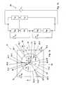
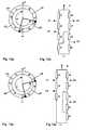
- FIG. 1ashows a potentiometer 10 with three segments 12.1, 12.2, 12.3 each having a contact page 14.1, 14.2 and 14.3.
- the contact side 14.1is bounded by an edge 16.1, which once runs around the segment 12.1.
- the contact page 14.2is bordered by an edge 16.2 and the contact side 14.3 by an edge 16.3.
- Similar objectseach have the same reference symbols with possibly different suffixes serving as numbering.
- the edge 16.1has a first section 18.1 and a second section 20.1.
- the edges 16.2 and 16.3respectively have first sections 18.1 and 18.3 and second sections 20.2 and 20.3.
- the segments 12.1, 12.2 and 12.3are in their first sections 18 and their second sections 20 each flush to each other, so that they are in electrical contact with each other.
- the segments 12.1, 12.2 and 12.3are each the same size and have a homogeneous, that is independent of the location, specific electrical resistance.
- the segment 12.1has a specific electrical resistance r1, which differs from a specific electrical resistance r2 of segment 12.2 and a specific electrical resistance r3 of segment 12.3.
- each two segmentsis an electrical contact.
- An electrical contact 22.2is between the segments 12.2. and 12.3 and an electrical contact 22.3 is disposed between the segments 12.3 and 12.1.
- Via the electrical contacts 22.1 to 22.3a voltage can be determined which drops across the respective segment.
- the contacts 22may also be arranged at any other locations of the segments, for example in the respective segment center.
- a predetermined current Ican be impressed via the electrical contacts 22.1 and 22.3, which can be emitted by a current source 24.1.
- a voltage source 24.2is provided, which applies a predetermined voltage U 1 of, for example, 5V to the electrical contacts 22.1 and 22.3.
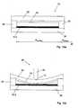
- FIG. 16ashows a section along the line A.
- the potentiometer 10comprises a carrier 26, on which the segments 12.1 to 12.3 are applied, wherein in FIG. 16a only the segment 12.2 is shown.
- the cover membrane 32is arranged, which hold a cover membrane 32 at a distance from the carrier 26.
- a flexible conductor 34fixed in the form of a silver layer, which has an annular shape and is spaced from the segments 12.1 to 12.3.
- a pressure with a coupling device 36 on the cover membrane 32causes the flexible conductor 34 deformed and so comes in contact with the respective segment, here with segment 12.2, in a contact point.
- an electrical contact between the flexible conductor 34 and the segment 12.2is produced.
- the cover membrane 32, the flexible conductor 34 and the coupling device 36are parts of a connecting device 38.
- the connecting devicemay also comprise known sliding contacts, which are rotatably mounted.
- FIG. 1ashows the coupling device 36 which is rotatably mounted in a center M by a rotation angle ⁇ .
- the coupling device 36presses in two contact points P 1 , P 2 on the cover membrane 32 (FIG. FIG. 16b ) and thus closes the corresponding segments, in FIG. 1a the segments 12.1 and 12.2, in the contact points P 1 and P 2 short.
- the voltage which drops between two segmentschanges.
- the two contact points P 1 and P 2are spaced from each other with respect to the center M by a spread angle ⁇ ( FIG. 1a ), which is larger than the angle range spanned by a segment, in the present case 120 °.
- FIG. 1bshows the corresponding to the rotation angle ⁇ equivalent circuit diagram for the potentiometer 10.
- the electrical resistance of each segment 12.1 to 12.3is divided into two partial resistors, which represent the electrical resistance in the clockwise direction in front of the contact point P 1 , P 2 and thereafter.
- the sum of the partial resistorswhich are designated by the suffix "a” and "b” respectively, corresponds to the total resistance r of the segment.
- the size of each of the partial resistorsdepends on the angle of rotation ⁇ if one of the two contact points P 1 or P 2 is located in the relevant segment.
- FIG. 2ashows the potentiometer 10, in which the coupling device 36 is at a different angle of rotation ⁇ , so that the contact point P 1 is located in the segment 12.3 and the contact point P 2 is located in the segment 12.1.
- FIG. 2bshown equivalent circuit diagram.
- FIG. 3ashows a third possible position of the coupling device 36, in which the first contact point P 1 is located in the segment 12.2 and the second contact point P 2 is in the segment 12.3. This results in the FIG. 3b shown equivalent circuit diagram.
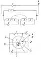
- FIG. 4ashows a second embodiment of a potentiometer 10 according to the invention with six segments 12.1, 12.2, 12.3, 12.4, 12.5 and 12.6.
- the segments 12.1 to 12.6are arranged as described above for the first embodiment. Between the individual segments electrical contacts 22.1 to 22.6 are arranged.
- the contacts 22.1 and 22.4are connected to a voltage source not shown, which is connected via the two electrical Contacts an electrical voltage V of example 5V applies, which has a current I result, which flows through all segments 12.1 to 12.6.
- FIGS. 5a, 5b . 6a, 6b . 7a, 7b . 8a, 8b . 9a, 9b . 10a, 10b . 11a, 11b . 12a, 12b . 13a, 13b . 14a, 14b and 15a or 15brespectively show the other possible positions of the coupling device 36 and the associated equivalent circuit diagrams.
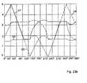
- FIGS. 23a . 23bis derived below, which voltages between individual electrical contacts 22.1 to 22.6 for different rotation angle ⁇ can be measured.
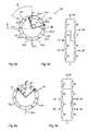
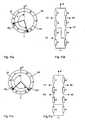
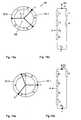
- Figure 17ashows an alternative embodiment of a potentiometer 10 according to the invention, which has two segments 12.1 and 12.2, the edges have 16.1 and 16.2.
- the edges 16.1 and 16.2border with their respective first sections 18.1 and 18.2 on the one hand and their second sections 20.1 and 20.2 on the other hand flush to each other so that they are in electrical contact with each other.
- the two segments 12.1, 12.2form an annular arrangement, in the center of which M a connecting device 38 is mounted rotatably about the center M.
- the connecting device 38has a first arm 40, a second arm 42 and a third arm 44, which at its end facing away from the midpoint M in a first contact point P 1 , in a second P 2 and in a third contact point P 3 in electrical Contact the respective segment. In this way sliding contacts are formed.
- an electrical current Iis impressed by a current source not shown, coming from the current source via the first arm 40 through the contact point P 1 , through the segment 12.1 or through the segments 12.1 and 12.2, flows back through the contact point P 2 and the second arm 42 to the power source.
- the first arm 40is electrically insulated from the second arm 42, so that a current flow from the first current contact to the second current contact through the two arms 40, 42 alone is not possible.
- an electrical voltage Ucan also be applied to the two current-carrying contacts 46, 48.
- an electrical voltageis formed between the contact points P 3 and P 1 and the contact points P 3 and P 2 , which voltage can be measured by a voltage measuring device, not shown. For this purpose, the voltage between the measuring contact 50 and the first current contact or the second current contact 48 is measured.
- FIG. 17bshows the equivalent circuit of the in Figure 17a shown potentiometer at the angular position ⁇ shown there.
- the notation of the resistorscorresponds to the notation for the two embodiments described above.
- FIG. 18ashows the potentiometer in a different angular position and FIG. 18b shows the associated equivalent circuit diagram.
- the voltages measured between the first contact point P 1 and the third contact point P 3 or the second contact point P 2 and the third contact point P 3can be calculated as follows for a given current I.
- a spread angle a between the two actuators of 90 °is assumed.
- the resistance coatingis assumed to be 10 ⁇ per degree (°).
- Each segment 12.1 to 12.6sweeps 60 ° so that the resistance of a segment is 600 ⁇ .
- FIG. 4aa voltage is applied between the terminals 22.1 (+ 5V) and 22.4 (ground) and the angle ⁇ accordingly FIG. 12a changed between 240 and 270 °, so there is an equivalent circuit loud FIG. 12b .
- FIG. 4aa voltage is applied between the terminals 22.1 (+ 5V) and 22.4 (ground) and the angle ⁇ accordingly FIG. 13a changed between 270 and 300 °, so there is an equivalent circuit loud FIG. 13b ,
- a method according to the inventionis carried out by passing a current I through the first and second energizing contacts 46 and 48, respectively.
- a voltage U or a current Iis applied.
- a voltage Uis first applied between the contact points P 1 and P 3 , then between the contact points P 2 and P 1 and then between P 3 and P 1 .
- the voltages U mess, U mess, 2 and U mess, 3 described aboveare measured.
- Each combination of these three voltagescorresponds exactly to a rotation angle ⁇ which is interpolated from a table stored in a digital memory of a microprocessor-based electrical evaluation circuit.
- a prosthesis according to the inventionpreferably comprises two elements pivotable relative to one another about a pivoting angle. Is it the prosthesis? for example, a knee prosthesis, so are the two legs of the thigh (shaft) and the lower leg. The two legs of the prosthesis are interconnected so that pivoting of the two legs relative to one another uniquely effects rotation of the connecting device relative to the segments.
- pivoting of the two legs relative to one anotherresults in movement of the connecting device of the potentiometer relative to the segments, and vice versa, rotational movement of the connecting device of the potentiometer relative to the segments of the potentiometer can only take place when the two legs are moved against each other.
- the anglecan be determined under which, for example, the lower leg is oriented relative to the thigh. If the prosthesis according to the invention is, for example, a forearm prosthesis, the two thighs are the upper arm (stump) and the lower arm. If the prosthesis is a finger prosthesis, the corresponding applies.
- the potentiometercomprises an electrical controller arranged to determine the rotational position of the potentiometer.
- the electrical controlis then preferably also surrounded by the enclosure. It is possible that the controller is configured to transmit the rotational position encoded wirelessly or wired outside the enclosure.
Landscapes
- Engineering & Computer Science (AREA)
- Microelectronics & Electronic Packaging (AREA)
- Physics & Mathematics (AREA)
- General Physics & Mathematics (AREA)
- Measurement Of Length, Angles, Or The Like Using Electric Or Magnetic Means (AREA)
- Transmission And Conversion Of Sensor Element Output (AREA)
- Agricultural Chemicals And Associated Chemicals (AREA)
Description
Translated fromGermanDie Erfindung betrifft ein Potentiometer, eine Prothese umfassend dieses Potentiometer, sowie ein Verfahren zum Ermitteln der Winkellage eines Bauteils mittels dieses Potentiometers. Potentiometer werden häufig zur Messung von Winkellagen eingesetzt, das heißt zur Ermittlung einer Verdrehung eines Körpers relativ zu einem anderen. Damit alle Winkellagen gemessen werden können, also kein Totwinkel entsteht, ist es notwendig, Modifikationen gegenüber herkömmlichen Potentiometern vorzunehmen. Ein Potentiometer ohne Totwinkel ist beispielsweise in der koreanischen Offenlegungsschrift
Aus der
Nachteilig an dem dort beschriebenen Potentiometer ist, dass die Schleifkontakte in einem Drehpunkt mit der Stromquelle verbunden werden müssen. Ein sich in diesem Punkt ändernder elektrischer Widerstand führt zu einem systematischen Messfehler. Nachteilig ist zudem, dass das Potentiometer nur in einem Winkelbereich von 0 bis 180° betreibbar ist. Es ist daher bei Anwendungen nicht verwendbar, bei denen beliebige Winkel einstellbar sein müssen.A disadvantage of the potentiometer described therein is that the sliding contacts must be connected in a pivot point with the power source. A change in this point electrical resistance leads to a systematic measurement error. Another disadvantage is that the potentiometer is operable only in an angular range of 0 to 180 °. It is therefore not suitable for applications in which any angle must be adjustable.
Aus der
Aus der
Der Erfindung liegt die Aufgabe zugrunde, ein robustes Potentiometer vorzuschlagen, mit dem die Winkellage eines Bauteils in allen Winkeln erfassbar ist.The invention has for its object to propose a robust potentiometer, with which the angular position of a component in all angles can be detected.
Die Erfindung löst das Problem durch ein Potentiometer gemäß Anspruch 1, eine Prothese gemäβ Anspruch 14 und ein Verfahren gemäβ Anspruch 15.The invention solves the problem by a potentiometer according to
Vorteilhaft an dem erfindungsgemäßen Potentiometer ist, dass kein Strom und auch keine Spannung von einem drehbar gelagerten Bauteil abgegriffen werden müssen. Es ist möglich, entweder nur die Segmente oder nur die Verbindungsvorrichtung elektrisch zu kontaktieren. Dadurch wird das Potentiometer besonders robust. Ein weiterer Vorteil ist, dass es einfach herstellbar und damit kostengünstig zu fertigen ist. Es ist zudem möglich, das Potentiometer offen zu bauen.An advantage of the potentiometer according to the invention is that no current and no voltage from a rotatably mounted component must be tapped. It is possible to electrically contact either only the segments or only the connection device. This makes the potentiometer particularly robust. Another advantage is that it is easy to manufacture and therefore inexpensive to manufacture. It is also possible to build the potentiometer open.
Vorteilhaft ist zudem, dass es in einer flachen Bauweise gefertigt werden kann. Ein weiterer Vorteil ist, dass das Potentiometer so kapselbar ist, dass innerhalb der Kapselung keine drehbar gelagerten Komponenten notwendig sind. Es wird so ein unter Wasser leicht einsetzbares, störungsresistentes Potentiometer erhalten.Another advantage is that it can be manufactured in a flat design. Another advantage is that the potentiometer can be encapsulated in such a way that no rotatably mounted components are required within the encapsulation. It is thus obtained under water easily usable, interference-resistant potentiometer.
Im Rahmen der vorliegenden Erfindung ist es möglich, nicht aber notwendig, dass die Verbindungsvorrichtung genau zwei Kontaktpunkte miteinander elektrisch verbindet. Möglich ist beispielsweise auch, dass die Verbindungsvorrichtung genau drei Kontaktpunkte miteinander verbindet. Es ist zudem möglich, nicht aber notwendig, dass die Verbindungsvorrichtung die Kontaktpunkte dauerhaft miteinander verbindet. So ist eine Verbindungsvorrichtung einsetzbar, bei der zeitweise kein Kontaktpunkt kontaktiert wird. Die Verbindungsvorrichtung kann die beiden Kontaktpunkte elektrisch überbrücken, das heißt mit einem im Vergleich zu sonstigen elektrischen Widerständen des Potentiometers kleinen Widerstand verbinden und so als Überbrückungsvorrichtung fungieren. Die Verbindungsvorrichtung kann aber auch die Kontaktpunkte dadurch verbinden, dass die Verbindungsvorrichtung an einem externen Stromkreis anschließbar ist, so dass ein Strom durch beide Kontaktpunkte fließt, In diesem Fall kann die Verbindungsvorrichtung so ausgebildet sein, dass die beiden Kontaktpunkte elektrisch gegeneinander isoliert sind, wenn die Verbindungsvorrichtung nicht mit dem externen Stromkreis verbunden ist.In the context of the present invention it is possible, but not necessary, for the connecting device to electrically connect exactly two contact points with one another. It is also possible, for example, that the connecting device connects exactly three points of contact with each other. It is also possible, but not necessary, for the connecting device to permanently connect the contact points. Thus, a connection device can be used in which no contact point is temporarily contacted. The connecting device can bridge the two contact points electrically, that is connect with a small compared to other electrical resistances of the potentiometer resistance and act as a bridging device. However, the connection device can also connect the contact points in that the connection device can be connected to an external circuit, so that a current flows through both contact points, in which case the Connecting device may be formed so that the two contact points are electrically insulated from each other when the connecting device is not connected to the external circuit.
Unter einer ringförmig geschlossenen Anordnung der Segmente wird insbesondere verstanden, dass die so angeordneten Segmente im mathematischen Sinne ein nicht einfach zusammenhängendes Gebiet bilden. Das Gebiet kann beispielsweise zweifach zusammenhängend sein. Es ist dazu möglich, nicht aber notwendig, dass die ringförmige Anordnung in der Mitte ein Loch aufweist. Es ist vielmehr ausreichend, wenn die Segmente eine solche ringförmige Anordnung bilden, dass der Strom in guter Näherung nicht durch eine Mitte zwischen den Segmenten hindurchfließt.An annularly closed arrangement of the segments is understood to mean, in particular, that the segments thus arranged form, in the mathematical sense, a region which is not simply connected. For example, the area may be doubly connected. It is possible, but not necessary, for the ring-shaped arrangement to have a hole in the middle. Rather, it is sufficient if the segments form such an annular arrangement that the current does not flow to a good approximation through a middle between the segments.
Unter einer Stromquelle wird insbesondere eine Vorrichtung verstanden, mittels der ein elektrischer Strom einer vorgegebenen Spannung oder eines vorgegebenen Stroms an zwei Kontakte angelegt werden kann.A current source is understood in particular to mean a device by means of which an electrical current of a predetermined voltage or a predetermined current can be applied to two contacts.
Erfindungsgemäß bilden die Segmente eine geschlossene insbesondere eine ringförmig geschlossene Anordnung. Auf diese Weise wird ein Drehpotentiometer erhalten, das besonders gut zum Messen von Winkel eingesetzt werden kann. Es ist jedoch nicht notwendig, dass die Segmente eine geschlossene Anordnung bilden. Es ist vielmehr auch möglich, dass die Segmente hintereinander angeordnet sind und damit eine Reihe bilden.According to the invention, the segments form a closed arrangement, in particular an annularly closed arrangement. In this way, a rotary potentiometer is obtained, which can be used particularly well for measuring angles. However, it is not necessary that the segments form a closed arrangement. Rather, it is also possible that the segments are arranged one behind the other and thus form a row.
Bevorzugt umfasst das Potentiometer elektrische Kontakte, über die ein durch alle Segmente fließender elektrischer Strom einprägbar ist. Es ist nicht notwendig, dass der Strom, der über die elektrischen Kontakte eingeprägt wird, stets durch alle Segmente fließt. Es ist beispielsweise möglich, dass die Verbindungsvorrichtung in einer Stellung ein gesamtes Segment überbrückt, so dass der elektrische Strom durch dieses Segment nicht oder nur zu einem verschwindend geringen Anteil fließt. Es ist insbesondere ausreichend, dass eine Stellung der Verbindungsvorrichtung existiert, in der über das Paar elektrischer Kontakte ein durch alle Segmente fließender elektrischer Strom einprägbar ist.Preferably, the potentiometer comprises electrical contacts, via which an electrical current flowing through all segments can be impressed. It is not necessary that the current impressed on the electrical contacts always flows through all the segments. It is possible, for example, for the connecting device to bridge over an entire segment in one position, so that the electrical current through this segment does not flow or flows only to a negligible proportion. It is particularly sufficient that a Position of the connecting device exists in the over the pair of electrical contacts an electrical current flowing through all segments can be impressed.
In einer bevorzugten Ausführungsform sind die Kontaktseiten eben und liegen in einer gemeinsamen Kontaktseitenebene. In anderen Worten bedeutet das, dass die Segmente so aneinander anschließen, dass sie eine durchgehende glatte gemeinsame Fläche bilden. In diesem Fall kann die Verbindungsvorrichtung besonders einfach über die gemeinsame Kontaktseitenebene gleiten.In a preferred embodiment, the contact sides are flat and lie in a common contact side plane. In other words, this means that the segments adjoin one another so that they form a continuous smooth common surface. In this case, the connecting device can slide particularly easily over the common contact side plane.
In einer bevorzugten Ausführungsform grenzt jedes Segment an genau zwei Nachbarn bündig an. Es ergibt sich so eine ringförmig geschlossene Anordnung. Besonders ist dabei jedes Segment mit beiden Nachbarn an den Stellen elektrisch verbunden, an denen sie bündig aneinander angrenzen. Es ist jedoch nicht notwendig, dass jedes Segment an genau zwei Nachbarn angrenzt.In a preferred embodiment, each segment is flush with exactly two neighbors. This results in a ring-shaped closed arrangement. In particular, each segment is electrically connected to both neighbors at the locations where they adjoin each other flush. However, it is not necessary for each segment to be adjacent to exactly two neighbors.
In einer bevorzugten Ausführungsform bilden die Segmente Kreisringsegmente. Diese Kreisringsegmente bilden einen geschlossenen Ring mit einer Ringbreite, die der Differenz zwischen Außenradius und Innenradius entspricht. Jedes Kreissegment hat dann zwei teilkreisförmig gebogene Begrenzungen und zwei gradlinig verlaufende Begrenzungen, wobei die Verlängerungen der gradlinig verlaufenden Begrenzungen sich in einem Mittelpunkt des Kreisrings treffen.In a preferred embodiment, the segments form circular ring segments. These circular ring segments form a closed ring with a ring width which corresponds to the difference between outer radius and inner radius. Each circle segment then has two part-circular curved boundaries and two rectilinear boundaries, the extensions of the rectilinear boundaries meet at a center of the annulus.
Besonders bevorzugt sind die Segmente jeweils gleich groß. Hierdurch wird ein besonders einfach zu fertigender Aufbau erhalten. Es ist bevorzugt, dass der spezifische elektrische Widerstand in einem Segment konstant ist. Der spezifische elektrische Widerstand gibt den elektrischen Widerstand an, der zwischen zwei Kontaktpunkten des Segments eines vorgegebenen Abstands anliegt. Besonders bevorzugt sind die spezifisch elektrischen Widerstände zweier benachbarter Segmente unterschiedlich. Die Größe des Unterschieds beträgt dabei beispielsweise mehr als 10 Prozent, bevorzugt aber mehr als 100 Prozent. Es ist auch möglich, dass der spezifische elektrische Widerstand zweier benachbarter Segmente ein Vielfaches voneinander beträgt.Particularly preferably, the segments are each the same size. As a result, a particularly easy-to-manufacture construction is obtained. It is preferable that the resistivity in a segment is constant. The electrical resistivity indicates the electrical resistance applied between two contact points of the segment of a predetermined distance. Particularly preferably, the specific electrical resistances of two adjacent segments are different. The size of the difference is, for example, more than 10 percent, but preferably more than 100 percent. It is also possible that the specific electrical resistance of two adjacent segments is a multiple of each other.
Besonders bevorzugt ist der spezifische elektrische Widerstand in allen Segmenten unterschiedlich. Hierdurch kann aus Messungen von Spannungen zwischen einzelnen Segmenten besonders einfach die Drehposition der Verbindungsvorrichtung ermittelt werden.Particularly preferably, the specific electrical resistance is different in all segments. As a result, the rotational position of the connecting device can be determined particularly easily from measurements of stresses between individual segments.
Besonders bevorzugt überbrückt die Verbindungsvorrichtung genau zwei Kontaktpunkte, so dass zwischen den beiden Kontaktpunkten ein im Vergleich zu sonstigen Widerständen des Potentiometers kleiner Widerstand besteht. Es ergibt sich ein besonders leicht auswertbares Spannungssignal zur Ermittlung einer Winkelstellung der Verbindungsvorrichtung.Particularly preferably, the connecting device bridges exactly two contact points, so that there is a small resistance between the two contact points in comparison to other resistances of the potentiometer. This results in a particularly easily evaluable voltage signal for determining an angular position of the connecting device.
Besonders bevorzugt ist die Verbindungsvorrichtung in einem Drehpunkt drehbar gelagert, wobei der Drehpunkt mit dem Kreisringmittelpunkt zusammenfällt. Auf diese Weise kann ein von dem Potentiometer ermitteltes Spannungsergebnis besonders leicht in einen Drehwinkel umgerechnet werden, den die Verbindungsvorrichtung um den Drehpunkt durchgeführt hat.Particularly preferably, the connecting device is rotatably mounted in a pivot point, wherein the pivot point coincides with the circular center of the ring. In this way, a voltage result determined by the potentiometer can be converted particularly easily into a rotation angle that the connecting device has performed around the pivot point.
In einer bevorzugten Ausführungsform ist die Verbindungsvorrichtung ausgebildet, um Kontaktpunkte zum elektrischen Verbinden von Kontaktpunkten der Segmente herzustellen, wobei jeweils zwei Kontaktpunkte bezüglich des Drehpunkts um einen Spreizwinkel versetzt sind und wobei mindestens ein Spreizwinkel so groß ist, dass die zugehörigen Kontaktpunkte nicht in einem Segment liegen können. Hierdurch werden vorteilhafterweise Zweideutigkeiten vermieden, so dass aus am Potentiometer gemessenen Spannungen stets eindeutig die Drehposition der Verbindungsvorrichtung ermittelt werden kann.In a preferred embodiment, the connecting device is designed to produce contact points for electrically connecting contact points of the segments, wherein two contact points are offset by a spread angle with respect to the pivot point and wherein at least one spread angle is so large that the associated contact points are not in a segment can. As a result, ambiguities are advantageously avoided, so that the rotational position of the connecting device can always be determined unambiguously from voltages measured at the potentiometer.
Bevorzugt umfasst die Verbindungsvorrichtung einen geschlossenen, flexiblen Leiter, der so zu den elektrisch leitenden Segmenten angeordnet ist, dass er durch Druck in einem Kontaktpunkt mit einem der Segmente in elektrischen Kontakt bringbar ist. Dazu wird beispielsweise ein flexibler elektrischer Leiter räumlich von den Kontaktseiten der Segmente beabstandet angeordnet. Durch Druck in dem Kontaktpunkt verformt sich der flexible Leiter und kommt in Kontakt mit der Kontaktseite des Segments, Wird an einer zweiten Stelle ebenfalls ein Druck auf den flexiblen Leiter aufgebracht, so gelangt der flexible Leiter an zwei Stellen in Kontakt mit Segmenten und stellt so einen elektrischen Kontakt zwischen beiden her. Der flexible Leiter weist vorzugsweise einen geringen elektrischen Widerstand auf. Beispielsweise ist der spezifisch elektrische Widerstand des flexiblen Leiters klein gegenüber dem spezifisch elektrischen Widerstand der Segmente.Preferably, the connection device comprises a closed, flexible conductor, which is arranged to the electrically conductive segments, that it can be brought into electrical contact by pressure in a contact point with one of the segments. For this purpose, for example, a flexible electrical conductor is arranged spatially spaced from the contact sides of the segments. By Pressure at the contact point causes the flexible conductor to deform and come into contact with the contact side of the segment. If pressure is also applied to the flexible conductor at a second location, the flexible conductor will come in contact with segments at two points, thus providing electrical continuity Contact between both. The flexible conductor preferably has a low electrical resistance. For example, the specific electrical resistance of the flexible conductor is small compared to the specific electrical resistance of the segments.
Die Segmente und Teile der Verbindungsvorrichtung, insbesondere der flexible Leiter, sind von einer flexiblen Umhüllung flüssigkeitsdicht umgeben. So wird vorteilhafterweise ein flüssigkeifsdichtes Potentiometer erhalten, das zur. Herstellung eines flüssigkeitsfesten Drehsensors verwendet werden kann.The segments and parts of the connecting device, in particular the flexible conductor, are surrounded by a flexible envelope liquid-tight. Thus, advantageously a flüssigkeifsdichtes potentiometer is obtained, the. Manufacture of a liquid-resistant rotary sensor can be used.
Bevorzugt umfasst das Potentiometer eine Koppeleinheit zum Aufbringen eines Drucks auf den flexiblen Leiter in mindestens zwei Kontaktpunkten. Diese Koppeleinheit ist beispielsweise Teil der Verbindungsvorrichtung. Beispielsweise ist die Koppeleinrichtung drehbar gelagert, so dass ein Verdrehen der Koppeleinrichtung dazu führt, dass der flexible Leiter an zwei sich verändernden Kontaktpunkten den ersten Kontaktpunkt in dem ersten Segment mit dem zweiten Kontaktpunkt in dem zweiten Segment verbindet. Auf diese Weise kann eine Drehstellung der Koppeleinrichtung auch in Flüssigkeitsumgebungen erfasst werden, die Segmente von einer flüssigkeitsdichten Umhüllung umgeben sind.Preferably, the potentiometer comprises a coupling unit for applying a pressure to the flexible conductor in at least two contact points. This coupling unit is for example part of the connecting device. For example, the coupling device is rotatably mounted, so that a rotation of the coupling device causes the flexible conductor connects the first contact point in the first segment with the second contact point in the second segment at two changing contact points. In this way, a rotational position of the coupling device can also be detected in fluid environments, the segments are surrounded by a liquid-tight envelope.
Erfindungsgemäß ist zwischen jeweils zwei Segmenten stets ein elektrischer Kontakt angeordnet. Über diesen elektrischen Kontakt ist eine elektrische Spannung abgreifbar, die über das Segment abfällt.According to the invention, an electrical contact is always arranged between each two segments. About this electrical contact, an electrical voltage can be tapped, which drops across the segment.
Bevorzugt umfasst das Potentiometer eine Spannungsermittlungsvorrichtung und eine Steuerung, die ausgebildet ist zum Verbinden von jeweils zwei Kontakten mit einer Stromquelle und zwei Kontakten mit der Spannungsermittlungsvorrichtung. Die Steuerung ist dabei dazu ausgebildet, ein erfindungsgemäßes Verfahren, wie es weiter unten beschrieben ist, durchzuführen. Bei den Kontakten kann es sich um mit Segmenten verbundene Kontakte oder um Kontakte der Verbindungsvorrichtung handeln.Preferably, the potentiometer comprises a voltage detection device and a controller, which is designed to connect in each case two contacts to a current source and two contacts to the voltage detection device. The controller is designed to carry out a method according to the invention, as described below. The contacts may be segmented contacts or contacts of the connector device.
In einer bevorzugten Ausführungsform verbindet die Verbindungsvorrichtung den ersten Kontaktpunkt in dem ersten Segment mit dem zweiten Kontaktpunkt in dem vom ersten Segment verschiedenen zweiten Segment und genau einem dritten Kontaktpunkt. Dieser dritte Kontaktpunkt liegt besonders bevorzugt stets in einem von dem ersten und zweiten Segment verschiedenen dritten Segment. Besonders günstig ist der Einsatz eines erfindungsgemäßen Potentiometers als Drehwinkelsensor in einer Prothese wie einer Arm- oder Handprothese. Durch die Kapselbarkeit kann die Prothese auch unter Wasser eingesetzt werden.In a preferred embodiment, the connection device connects the first contact point in the first segment with the second contact point in the second segment different from the first segment and exactly one third contact point. This third contact point is particularly preferably always located in a third segment that is different from the first and second segments. Particularly advantageous is the use of a potentiometer according to the invention as a rotation angle sensor in a prosthesis such as an arm or hand prosthesis. Due to the capsule, the prosthesis can also be used under water.
Ein erfindungsgemäßes Verfahren umfasst bevorzugt den Schritt des Anlegens des elektrischen Stroms an ein zweites Paar elektrischer Kontakte, nachdem an dem ersten Paar elektrischer Kontakte eine erste Spannung ermittelt worden ist.A method according to the invention preferably comprises the step of applying the electrical current to a second pair of electrical contacts after a first voltage has been determined on the first pair of electrical contacts.
Dadurch ist das Verfahren mit nur einer Stromquelle und nur einer Spannungsermittlungsvorrichtung durchführbar. Insbesondere umfasst das Verfahren das Ermitteln von Endspannungen zwischen Endpaaren elektrischer Kontaktierungen, wobei n > 1 gilt und wobei die n Paare so gewählt sind, dass jede Drehposition der Verbindungsvorrichtung genau einer Kombination der Endspannungen entspricht. Hierdurch kann aus den gemessenen Spannungen auf eindeutige Weise die Drehposition der Verbindungsvorrichtung zugeordnet werden.As a result, the method with only one power source and only one voltage detection device is feasible. In particular, the method comprises determining terminal voltages between end pairs of electrical contacts, where n> 1, and wherein the n pairs are chosen such that each rotational position of the connecting device corresponds exactly to a combination of the final voltages. In this way, the rotational position of the connecting device can be uniquely assigned from the measured voltages.
Das erfindungsgemäße Potentiometer kann eine Verbindungsvorrichtung aufweisen, die an zwei, drei, vier oder fünf Kontaktstellen mit den Segmenten in Kontakt steht. Besonders einfach aufgebaute Ausführungsformen kommen jedoch mit zwei oder drei Kontaktstellen aus.The potentiometer according to the invention may comprise a connecting device which is in contact with the segments at two, three, four or five contact points. However, embodiments with a particularly simple structure have two or three contact points.
Im Folgenden werden Ausführungsbeispiele die Erfindung anhand der beigefügten Zeichnungen näher beschrieben. Es zeigt
Figur 1a- eine schematische Ansicht eines ersten erfindungsgemäßen Potentiometers mit drei Segmenten und einer Verbindungsvorrichtung in einer ersten Stellung,
Figur 1b- ein Ersatzschaltbild des
Potentiometers gemäß Figur 1a , Figur 2a- das
Potentiometer nach Figur 1a mit einer anderen Stellung der Verbindungsvorrichtung, - Figur 2b
- das Ersatzschaltbild für das Potentiometer mit der in
Figur 2a Figur 3a- das Potentiometer aus
den Figuren 1a und2a mit einer dritten Stellung der Verbindungsvorrichtung, und Figur 3bdas zu Figur 3a gehörige Ersatzschaltbild.- Figur 4a
- zeigt eine zweite Ausführungsform eines erfindungsgemäßen Potentiometers mit sechs Segmenten, bei dem die Verbindungsvorrichtung in einer ersten Position ist und
- Figur 4b
- zeigt das zugehörige Ersatzschaltbild.
- Figur 5a
- zeigt das Potentiometer nach
Figur 4a , bei dem die Verbindungsvorrichtung in einer zweiten Position ist und - Figur 5b
- zeigt das zugehörige Ersatzschaltbild.
- Figur 6a
- zeigt das Potentiometer nach
Figur 4a , bei dem die Verbindungsvorrichtung in einer dritten Position ist und - Figur 6b
- zeigt das zugehörige Ersatzschaltbild.
- Figur 7a
- zeigt das Potentiometer nach
Figur 4a , bei dem die Verbindungsvorrichtung in einer vierten Position ist und - Figur 7b
- zeigt das zugehörige Ersatzschaltbild.
- Figur 8a
- zeigt das Potentiometer nach
Figur 4a , bei dem die Verbindungsvorrichtung in einer fünften Position ist und - Figur 8b
- zeigt das zugehörige Ersatzschaltbild.
- Figur 9a
- zeigt das Potentiometer nach
Figur 4a , bei dem die Verbindungsvorrichtung in einer sechsten Position ist und - Figur 9b
- zeigt das zugehörige Ersatzschaltbild.
- Figur 10a
- zeigt das Potentiometer nach
Figur 4a , bei dem die Verbindungsvorrichtung in einer siebten Position ist und - Figur 10b
- zeigt das zugehörige Ersatzschaltbild.
- Figur 11a
- zeigt das Potentiometer nach
Figur 4a , bei dem die Verbindungsvorrichtung in einer achten Position ist und - Figur 11b
- zeigt das zugehörige Ersatzschaltbild.
- Figur 12a
- zeigt das Potentiometer nach
Figur 4a , bei dem die Verbindungsvorrichtung in einer neunten Position ist und - Figur 12b
- zeigt das zugehörige Ersatzschaltbild.
- Figur 13a
- zeigt das Potentiometer nach
Figur 4a , bei dem die Verbindungsvorrichtung in einer zehnten Position ist und Figur 13b- zeigt das zugehörige Ersatzschaltbild.
- Figur 14a
- zeigt das Potentiometer nach
Figur 4a , bei dem die Verbindungsvorrichtung in einer elften Position ist und - Figur 14b
- zeigt das zugehörige Ersatzschaltbild.
- Figur 15a
- zeigt das Potentiometer nach
Figur 4a , bei dem die Verbindungsvorrichtung in einer zwölften Position ist, - Figur 15b
- zeigt das zugehörige Ersatzschaltbild. Die
- Figuren16a und 16 b
- zeigen einen Querschnitt entlang der Linie A gemäß der
Figuren 1a4a . Die - Figuren 17a, 17b, 18a, 18b,
- 19a, 19b, 20a, 20b,
- 21 a, 21 b, 22a und 22b
- zeigen eine dritte Ausführungsform eines erfindungsgemäßen Potentiometers und die jeweils zugehörigen Ersatzschaltbilder. Die
- Figuren 23a, 23b
- sind Diagramme, die die Abhängigkeit von an Kontakten des Potentiometers gemäß den
Figuren 4a bis 15b abfallenden Spannungen in Abhängigkeit vom Drehwinkel der Verbindungsvorrichtung darstellen. Figur 24- ist ein sich aus Teilberechnungen resultierender Kurvenverlauf der Spannung über 360° des Drehwinkels für ein Potentiometer gemäß den
Figuren 17a bis 22b .
- FIG. 1a
- 1 is a schematic view of a first potentiometer according to the invention with three segments and a connecting device in a first position,
- FIG. 1b
- an equivalent circuit diagram of the potentiometer according to
FIG. 1a . - FIG. 2a
- the potentiometer after
FIG. 1a with another position of the connection device, - FIG. 2b
- the equivalent circuit diagram for the potentiometer with the in
FIG. 2a shown position, - FIG. 3a
- the potentiometer out of the
FIGS. 1a and2a with a third position of the connecting device, and - FIG. 3b
- that too
FIG. 3a associated equivalent circuit diagram. - FIG. 4a
- shows a second embodiment of a six-segment potentiometer according to the invention, in which the connecting device is in a first position and
- FIG. 4b
- shows the associated equivalent circuit diagram.
- FIG. 5a
- shows the potentiometer after
FIG. 4a in which the connection device is in a second position and - FIG. 5b
- shows the associated equivalent circuit diagram.
- FIG. 6a
- shows the potentiometer after
FIG. 4a in which the connection device is in a third position and - FIG. 6b
- shows the associated equivalent circuit diagram.
- Figure 7a
- shows the potentiometer after
FIG. 4a in which the connection device is in a fourth position and - FIG. 7b
- shows the associated equivalent circuit diagram.
- FIG. 8a
- shows the potentiometer after
FIG. 4a in which the connection device is in a fifth position and - FIG. 8b
- shows the associated equivalent circuit diagram.
- FIG. 9a
- shows the potentiometer after
FIG. 4a in which the connection device is in a sixth position and - FIG. 9b
- shows the associated equivalent circuit diagram.
- FIG. 10a
- shows the potentiometer after
FIG. 4a in which the connection device is in a seventh position and - FIG. 10b
- shows the associated equivalent circuit diagram.
- FIG. 11a
- shows the potentiometer after
FIG. 4a in which the connecting device is in an eighth position and - FIG. 11b
- shows the associated equivalent circuit diagram.
- FIG. 12a
- shows the potentiometer after
FIG. 4a in which the connection device is in a ninth position and - FIG. 12b
- shows the associated equivalent circuit diagram.
- FIG. 13a
- shows the potentiometer after
FIG. 4a in which the connection device is in a tenth position and - FIG. 13b
- shows the associated equivalent circuit diagram.
- Figure 14a
- shows the potentiometer after
FIG. 4a in which the connecting device is in an eleventh position and - FIG. 14b
- shows the associated equivalent circuit diagram.
- FIG. 15a
- shows the potentiometer after
FIG. 4a in which the connection device is in a twelfth position, - FIG. 15b
- shows the associated equivalent circuit diagram. The
- Figures 16a and 16b
- show a cross section along the line A according to the
FIGS. 1a and4a , The - FIGS. 17a, 17b, 18a, 18b,
- 19a, 19b, 20a, 20b,
- 21a, 21b, 22a and 22b
- show a third embodiment of a potentiometer according to the invention and the respective associated equivalent circuit diagrams. The
- FIGS. 23a, 23b
- are diagrams showing the dependence on contacts of the potentiometer according to the
FIGS. 4a to 15b represent decreasing voltages depending on the rotation angle of the connecting device. - FIG. 24
- is a resulting from part calculations curve of the voltage over 360 ° of the rotation angle for a potentiometer according to the
FIGS. 17a to 22b ,
Die Kante 16.1 besitzt einen ersten Abschnitt 18.1 und einen zweiten Abschnitt 20.1. Auf gleiche Weise besitzen die Kanten 16.2 bzw. 16.3 erste Abschnitte 18.1 bzw. 18.3 und zweite Abschnitte 20.2 bzw. 20.3. Die Segmente 12.1, 12.2 und 12.3 liegen in ihren ersten Abschnitten 18 und ihren zweiten Abschnitten 20 jeweils bündig aneinander an, so dass sie in elektrischem Kontakt miteinander stehen. Durch das Angrenzen bilden die Segmente 12.1 bis 12.3, die als Kreisringsegmente ausgebildet sind, einen geschlossenen Kreisring, bei dem jedes Segment mit genau zwei benachbarten Segmenten aufgrund ihres bündigen Kontakts elektrisch miteinander verbunden ist.The edge 16.1 has a first section 18.1 and a second section 20.1. In the same way, the edges 16.2 and 16.3 respectively have first sections 18.1 and 18.3 and second sections 20.2 and 20.3. The segments 12.1, 12.2 and 12.3 are in their first sections 18 and their
Die Segmente 12.1, 12.2 und 12.3 sind jeweils gleich groß und weisen einen homogenen, das heißt vom Ort unabhängigen, spezifischen elektrischen Widerstand auf. So besitzt das Segment 12.1 einen spezifischen elektrischen Widerstand r1, der sich von einem spezifischen elektrischen Widerstand r2 von Segment 12.2 und einem spezifischen elektrischen Widerstand r3 von Segment 12.3 unterscheidet.The segments 12.1, 12.2 and 12.3 are each the same size and have a homogeneous, that is independent of the location, specific electrical resistance. Thus, the segment 12.1 has a specific electrical resistance r1, which differs from a specific electrical resistance r2 of segment 12.2 and a specific electrical resistance r3 of segment 12.3.
Zwischen jeweils zwei Segmenten befindet sich ein elektrischer Kontakt. So befindet sich ein elektrischer Kontakt 22.1 zwischen den Segmenten 12.1 und 12.2. Ein elektrischer Kontakt 22.2 ist zwischen den Segmenten 12.2. und 12.3 und ein elektrischer Kontakt 22.3 ist zwischen den Segmenten 12.3 und 12.1 angeordnet. Über die elektrischen Kontakte 22.1 bis 22.3 kann eine Spannung ermittelt werden, die über das jeweilige Segment abfällt. In einer alternativen Ausführungsform können die Kontakte 22 auch an beliebigen anderen Stellen der Segmente angeordnet sein, beispielsweise in der jeweiligen Segmentmitte.Between each two segments is an electrical contact. Thus, there is an electrical contact 22.1 between the segments 12.1 and 12.2. An electrical contact 22.2 is between the segments 12.2. and 12.3 and an electrical contact 22.3 is disposed between the segments 12.3 and 12.1. Via the electrical contacts 22.1 to 22.3, a voltage can be determined which drops across the respective segment. In an alternative embodiment, the contacts 22 may also be arranged at any other locations of the segments, for example in the respective segment center.
Über die elektrischen Kontakte 22.1 und 22.3 ist ein vorgegebener Strom I einprägbar, der von einer Stromquelle 24.1 abgegeben werden kann. Alternativ ist eine Spannungsquelle 24.2 vorhanden, die an die elektrischen Kontakte 22.1 und 22.3 eine vorgegebene Spannung U1 von beispielsweise 5V anlegt.A predetermined current I can be impressed via the electrical contacts 22.1 and 22.3, which can be emitted by a current source 24.1. Alternatively, a voltage source 24.2 is provided, which applies a predetermined voltage U1 of, for example, 5V to the electrical contacts 22.1 and 22.3.
Die in
Wie
Die beiden Kontaktpunkte P1 und P2 liegen bezüglich des Mittelpunkts M um einen Spreizwinkel α voneinander beabstandet (
Aus dem in
Anhand der in den
Die
Die beiden Segmente 12.1, 12.2 bilden eine kreisringförmige Anordnung, in deren Mittelpunkt M eine Verbindungsvorrichtung 38 drehbar um den Mittelpunkt M gelagert ist. Die Verbindungsvorrichtung 38 weist einen ersten Arm 40, einen zweiten Arm 42 und einen dritten Arm 44 auf, die an ihrem dem Mittelpunkt M abgewandten Ende in einem ersten Kontaktpunkt P1, in einem zweiten P2 bzw. in einem dritten Kontaktpunkt P3 in elektrischem Kontakt mit dem jeweiligen Segment stehen. Auf diese Weise werden Schleifkontakte gebildet.The two segments 12.1, 12.2 form an annular arrangement, in the center of which M a connecting
Über einen ersten Bestromungskontakt 46 und einen zweiten Bestromungskontakt 48 wird durch eine nicht eingezeichnete Stromquelle ein elektrischer Strom I aufgeprägt, der von der Stromquelle kommend über den ersten Arm 40 durch den Kontaktpunkt P1, durch das Segment 12.1 oder durch die Segmente 12.1 und 12.2, durch den Kontaktpunkt P2 und den zweiten Arm 42 zur Stromquelle zurückfließt. Der erste Arm 40 ist gegen den zweiten Arm 42 elektrisch isoliert, so dass ein Stromfluss vom ersten Bestromungskontakt zum zweiten Bestromungskontakt durch die beiden Arme 40, 42 allein nicht möglich ist. Alternativ kann anstelle des elektrischen Stroms I auch eine elektrische Spannung U an die beiden Bestromungskontakte 46, 48 angelegt werden.Via a first
Aufgrund des oben beschriebenen elektrischen Stroms bildet sich zwischen den Kontaktpunkten P3 und P1 und den Kontaktpunkten P3 und P2 eine elektrische Spannung aus, die von einer nicht eingezeichneten Spannungsmessvorrichtung gemessen werden kann. Dazu wird die Spannung zwischen dem Messkontakt 50 und dem ersten Bestromungskontakt bzw. dem zweiten Bestromungskontakt 48 gemessen.Due to the electric current described above, an electrical voltage is formed between the contact points P3 and P1 and the contact points P3 and P2 , which voltage can be measured by a voltage measuring device, not shown. For this purpose, the voltage between the measuring
Die
Aus den in den
Für die Berechnungen wird ein Spreizwinkel a zwischen den beiden Betätigungselementen von 90° angenommen. Für den Widerstandsbelag wird ein Wert von 10Ω pro Grad (°) angenommen. Jedes Segment 12.1 bis 12.6 überstreicht 60°, so dass der Widerstand eines Segments 600Ω beträgt.For the calculations, a spread angle a between the two actuators of 90 ° is assumed. The resistance coating is assumed to be 10Ω per degree (°). Each segment 12.1 to 12.6 sweeps 60 ° so that the resistance of a segment is 600Ω.
Wird laut
Die Teilwiderstände in der
Mittels Hilfe der Kirchhoff'schen Gesetze ergibt sich der in
Wird laut zwischen den Anschlüssen 22.1 (+ 5V) und 22.4 (Masse) eine Spannung U angelegt und der Winkel ϕ entsprechend
Mittels Hilfe der Kirchhoff'schen Gesetze ergibt sich der in der
Wird der Winkel ϕ entsprechend
Mittels Hilfe der Kirchoff'schen Gesetze ergibt sich der in
Wird der Winkel ϕ entsprechend
Mittels Hilfe der Kirchoff'schen Gesetze ergibt sich der in
Wird der Winkel ϕ entsprechend
Mittels Hilfe der Kirchhoff'schen Gesetze ergibt sich der in
Wird der Winkel ϕ entsprechend
Mittels Hilfe der Kirchhoff'schen Gesetze ergibt sich der in
Wird der Winkel ϕ entsprechend
Mittels Hilfe der Kirchhoff'schen Gesetze ergibt sich der in
Wird der Winkel ϕ entsprechend
Mittels Hilfe der Kirchhoff'schen Gesetze ergibt sich der in
Wird laut
Mittels Hilfe der Kirchhoff'schen Gesetze ergibt sich der in
Wird laut
Die Teilwiderstände in der
Mittels Hilfe der Kirchhoff'sehen Gesetze ergibt sich der in
Wird der Winkel ϕ entsprechend
Mittels Hilfe der Kirchhoff'schen Gesetze ergibt sich der in
Wird der Winkel ϕ entsprechend
Mittels Hilfe der Kirchhoff'schen Gesetze ergibt sich der in
Über 0° ≤ ϕ ≤ 360° ergibt sich so insgesamt der in
Wird zwischen an den Kontakt 22.2 (
Zum Ermitteln des Drehwinkels ϕ aus den gemessenen SpannungenFor determining the angle of rotation φ from the measured voltages
Zunächst wird eine Spannung U = 5V zwischen den Kontakten 22.1 und 22.4 angelegt. Es versteht sich, dass keiner der Kontakte geerdet sein muss; es werden dann die oben beschriebenen Spannungen zum Potential des Kontakts 22.4 gemessen. Es wird sodann überprüft, ob die Bedingungen U4 = 3,33 ± 0,2 V und U3 = 1,66 ± 0,2 V erfüllt sind. Wenn ja, wird wie weiter unten beschrieben ist, aus den Spannungen U4 und U3 der Drehwinkel bestimmt. Wenn nein, wird die Spannung U über die entgegen dem Uhrzeigersinn nächsten Kontakte 22.2 und 22.5 angelegt.First, a voltage U = 5V is applied between the contacts 22.1 and 22.4. It is understood that none of the contacts must be grounded; the voltages described above for the potential of the contact 22.4 are then measured. It is then checked whether the conditions U4 = 3.33 ± 0.2 V and U3 = 1.66 ± 0.2 V are met. If so, as described below, the rotation angle is determined from the voltages U4 and U3. If not, the voltage U is applied via the next counterclockwise contacts 22.2 and 22.5.
In
Es werden also lange die Kontakte, über die die Spannung U angelegt wird, um jeweils 1 Segment (β = 60°) weitergeschaltet, bis die Bedingungen U4 = 3,33 ± 0,2 V und U3 = 1,66 ± 0,2 V erfüllt sind.Thus, for a long time, the contacts over which the voltage U is applied are incremented by 1 segment each (β = 60 °) until the conditions U4 = 3.33 ± 0.2 V and U3 = 1.66 ± 0.2 V are fulfilled.
Der Drehwinkel ϕ kann aus den gemessenen Spannungen wie folgt berechnet werden.
- Wenn U1 > ½ U = 2,5 V ist, gilt: ϕ = (β + (900 - 2,5 * U1)/5) mod 360,
- Wenn U1 ≤ ½ U = 2,5 V ist, gilt: ϕ = (β + (900 - 2,5 * U2)/5) mod 360
- If U1> ½ U = 2.5V, then: φ = (β + (900 - 2.5 * U1) / 5) mod 360,
- If U1 ≤ ½ U = 2.5 V then: φ = (β + (900 - 2.5 * U2) / 5) mod 360
Dabei bezeichnet mod 360 die Modularfunktion, für die (a+ z 360°) mod 360 = a für alle a zwischen 0° und 360° und alle ganzen Zahlen z gilt.Where mod 360 denotes the modular function for which (a + z 360 °) mod 360 = a for all a between 0 ° and 360 ° and all integers z.
Für die in
Für die folgenden Berechnungen wird ein Spreizwinkel α zwischen den drei Armen 40, 42, 44 von α = 120° angenommen. Für den Widerstandsbelag wird ein Wert von 10 Ω pro Grad für das Segment 12.2 und 100 Q pro Grad für das Segment 12.1 angenommen.For the following calculations, a spread angle α between the three
Wird über den ersten Bestromungskontakt 46 des ersten Arms 40 und den Messkontakt 50 des Arms 44 (
Wird, wie in
Wird, wie in
Wird, wie in
Wird, wie in
Wird, wie in
Aus den obigen Teilberechnungen ergibt sich für eine Spannung U = 5V der in
Wird zwischen den Anschlüssen P2 (+ 5V) und P1 (Masse) eine Spannung U angelegt und die Spannung Umess,2 an P3 gemessen, ergibt sich ein um den Weiterschaltwinkel β = -120° verschobener Kurvenverlauf.If a voltage U is applied between the terminals P2 (+ 5V) and P1 (ground) and the voltage Umess, 2 is measured at P3 , the result is a curve progression shifted by the stepping angle β = -120 °.
Wird zwischen den Anschlüssen P3 (+ 5V) und P2 (Masse) eine Spannung angelegt und die Spannung Umess,3 an P1 gemessen, ergibt sich ein um den Weiterschaltwinkel β = +120° verschobener Kurvenverlauf.If a voltage is applied between the terminals P3 (+ 5V) and P2 (ground) and the voltage Umess, 3 is measured at P1 , the result is a shift of the shift angle β = + 120 °.
Für die Messung des Winkels wird eine Spannung U zunächst zwischen den Kontaktpunkten P1 und P3 angelegt, anschließend zwischen den Kontaktpunkten P2 und P1 und danach zwischen P3 und P1. Es werden jeweils die oben beschriebenen Spannungen Umess, Umess,2 und Umess,3 gemessen. Jeder Kombination dieser drei Spannungen entspricht genau ein Drehwinkel ϕ, der aus einer Tabelle interpoliert wird, die aus in einem digitalen Speicher einer elektrischen Auswerteschaltung in Form eines Mikroprozessors gespeichert ist.For the measurement of the angle, a voltage U is first applied between the contact points P1 and P3 , then between the contact points P2 and P1 and then between P3 and P1 . In each case, the voltages Umess, Umess, 2 and Umess, 3 described above are measured. Each combination of these three voltages corresponds exactly to a rotation angle φ which is interpolated from a table stored in a digital memory of a microprocessor-based electrical evaluation circuit.
Eine erfindungsgemäße Prothese umfasst bevorzugt zwei gegeneinander um einen Schwenkwinkel verschwenkbare Elemente. Handelt es sich bei der Prothese beispielsweise um eine Knieprothese, so sind die beiden Schenkel der Oberschenkel (Schaft) und der Unterschenkel. Die beiden Schenkel der Prothese werden so miteinander verbunden, dass ein Schwenken der beiden Schenkel gegeneinander auf eineindeutige Weise eine Drehung der Verbindungsvorrichtung relativ zu den Segmenten bewirkt.A prosthesis according to the invention preferably comprises two elements pivotable relative to one another about a pivoting angle. Is it the prosthesis? for example, a knee prosthesis, so are the two legs of the thigh (shaft) and the lower leg. The two legs of the prosthesis are interconnected so that pivoting of the two legs relative to one another uniquely effects rotation of the connecting device relative to the segments.
In anderen Worten führt ein Schwenken der beiden Schenkel zueinander zu einer Bewegung der Verbindungsvorrichtung des Potentiometers relativ zu den Segmenten und umgekehrt kann eine Drehbewegung der Verbindungsvorrichtung des Potentiometers relativ zu den Segmenten des Potentiometers nur dann erfolgen, wenn die beiden Schenkel gegeneinander bewegt werden.In other words, pivoting of the two legs relative to one another results in movement of the connecting device of the potentiometer relative to the segments, and vice versa, rotational movement of the connecting device of the potentiometer relative to the segments of the potentiometer can only take place when the two legs are moved against each other.
Mit Hilfe des Potentiometers kann dann, wie oben beschrieben, der Winkel bestimmt werden, unter dem beispielsweise der Unterschenkel relativ zum Oberschenkel orientiert ist. Handelt es sich bei der erfindungsgemäßen Prothese beispielsweise um eine Unterarmprothese, so sind die beiden Schenkel der Oberarm (Stumpf) und der Unterarm. Ist die Prothese eine Fingerprothese, gilt entsprechendes.With the help of the potentiometer can then, as described above, the angle can be determined under which, for example, the lower leg is oriented relative to the thigh. If the prosthesis according to the invention is, for example, a forearm prosthesis, the two thighs are the upper arm (stump) and the lower arm. If the prosthesis is a finger prosthesis, the corresponding applies.
Besonders günstig ist es, wenn die Segmente und der flexible Leiter von einer flexiblen Umhüllung flüssigkeitsdicht umgeben sind. In diesem Fall kann die Prothese in Wasser getaucht werden, ohne dass ein Kurzschluss zu befürchten ist. Es ist möglich, dass das Potentiometer eine elektrische Steuerung umfasst, die eingerichtet ist zum Ermitteln der Drehposition des Potentiometers. Die elektrische Steuerung ist dann vorzugsweise ebenfalls von der Umhüllung umgeben. Es ist möglich, dass die Steuerung ausgebildet ist, um die Drehposition kodiert drahtlos oder drahtgebunden nach außerhalb der Umhüllung zu senden.It is particularly favorable when the segments and the flexible conductor are surrounded in a liquid-tight manner by a flexible envelope. In this case, the prosthesis can be immersed in water without fear of a short circuit. It is possible that the potentiometer comprises an electrical controller arranged to determine the rotational position of the potentiometer. The electrical control is then preferably also surrounded by the enclosure. It is possible that the controller is configured to transmit the rotational position encoded wirelessly or wired outside the enclosure.
- 1010
- Potentiometerpotentiometer
- 12.1, 12.2, 12.3, 12.4, 12.5, 12.612.1, 12.2, 12.3, 12.4, 12.5, 12.6
- Segmentsegment
- 1414
- KontaktseiteContact
- 1616
- Kanteedge
- 1818
- erster Abschnittfirst section
- 2020
- zweiter Abschnittsecond part
- 2222
- elektrischer Kontaktelectric contact
- 2424
- Stromquellepower source
- 2626
- Trägercarrier
- 2828
- innerer Abstandsringinner spacer ring
- 3030
- äußerer Abstandsringouter spacer ring
- 3232
- Druckmembranpressure membrane
- 3434
- flexibler Leiterflexible conductor
- 3636
- Koppeleinrichtungcoupling device
- 3838
- Verbindungsvorrichtungconnecting device
- 4040
- erster Armfirst arm
- 4242
- zweiter Armsecond arm
- 4444
- dritter Armthird arm
- 4646
- erster Bestromungskontaktfirst current contact
- 4848
- zweiter Bestromungskontaktsecond current contact
- 5050
- Messkontaktmeasuring contact
- II
- Stromelectricity
- Kufenskids
- äußerer Kreisringradiusouter circle radius
- KinnenTurkish women
- innerer Kreisringradiusinner circle radius
- MM
- MittelpunktFocus
- ϕφ
- Drehwinkelangle of rotation
- αα
- Spreizwinkelsplay
- ββ
- WeiterschaltwinkelAdvance angle
- P1, P2, P3P1 , P2 , P3
- PunktPoint
- rr
- Widerstandresistance
- UU
- Spannungtension
Claims (15)
- A potentiometer with(a) at least two electrically conductive segments (12),- which each comprise a contact side (14) that is bordered by an edge (16),- which each sit flush by one another with a section (18, 20) of their edges (16) and form a closed, particularly a closed ring-shaped, arrangement,(b) a connecting device (38) to electrically connect a first contact point (P1) in a first segment with at least a second contact point (P2, P3) in a second segment that is different to the first segment,
characterized by the fact that(c) an electrical contact (22) is always arranged between each of the two segments (12). - The potentiometer according to one of the above claims,characterized by electrical contacts (22) via which an electrical current (I) can be passed through all segments.
- The potentiometer according to one of the above claims,characterized by the fact that the contact sides (14) are even and are situated at a common contact side level.
- The potentiometer according to one of the above claims,characterized by the fact that each segment (12) sits flush against exactly two neighbours and has electrical contact with the two neighbours at points where they sit flush against one another.
- The potentiometer according to one of the above claims,characterized by the fact that the segments (12) are circular segments, the segments (12) each being equal in size and the specific electrical resistance in one segment (12) being constant.
- The potentiometer according to one of the above claims,characterized by the fact that the connecting device (38) connects exactly two contact points (P1, P2).
- The potentiometer according to one of the above claims 5 or 6,characterized by the fact that the connecting device (38) is mounted in a pivot (M) in such a way that it can be rotated, and the pivot (M) coincides with a centre of a ring, the connecting device (38) being designed in such a way that the first contact point (P1) is arranged offset from the second contact point (P2) at a spread angle (a) which is so large that the contact points (P1, P2) cannot be located in one segment.
- The potentiometer according to one of the above claims,characterized by the fact that the connecting device (38) comprises a closed, flexible conductor (34) which is arranged in relation to the electrically conductive segments (12) in such a way that electrical contact can be made with one of the segments (12) by means of the pressure at one contact point (P1, P2).
- The potentiometer according to claim 8,characterized by a coupling device (36) to apply pressure on the flexible conductor (34) an at least two contact points (P1, P2).
- The potentiometer according to one of the above claims,characterized by a voltage determination device and a control system that is designed to electrically connect two contacts (22) with a voltage source or current source and at least one, in particular two, contacts (22) with the voltage determination device.
- The potentiometer according to one of the claims 1 to 5 or 7 to 10,characterized by the fact that the connecting device (38) is designed to connect the first contact point (P1) in the first segment with the second contact point (P2) in the second segment, which is different to the first segment, and to connect exactly a third contact point (P3), with all three contact points (P1, P2, P3) always being located in different segments.
- The potentiometer according to claim 11,characterized by the fact that the connecting device (38) comprises a first arm (40), a second arm (42) and a third arm (44), the first arm (40) and the second arm (42) each being able to connect with a power source via a current contact (46, 48), and the third arm (44) being able to connect with the voltage determination device via a measuring contact (50), the three arms (40, 42, 44) being electrically insulated from each other.
- The potentiometer according to one of the above claims,characterized by the fact that at least two adjacent, especially all, segments (12) have different electrical resistances.
- A prothesis, in particular a prosthetic arm or hand, with a potentiometer (10) according to one of the above claims.
- A process to calculate an angle position of a component with the steps:(a) the component is mechanically connected to a connecting apparatus (38) or the segments (12) of a potentiometer (10) as claimed in one of the preceding claims,(b) a current source or a voltage source is connected to the potentiometer (10), so that an electric current (I) flows through at least one segment (12),(c) at least one first voltage (U1, Umess) which drops across a portion of the potentiometer (10) on the basis of the current (I) is ascertained"(d) the at least one voltage is used to ascertain a rotary position for the connecting apparatus (38), and(e) the rotary position (ϕ) of the connecting apparatus (38) is used to ascertain the angular position of the component.
Applications Claiming Priority (3)
| Application Number | Priority Date | Filing Date | Title |
|---|---|---|---|
| DE102007004536 | 2007-01-24 | ||
| DE102007014751ADE102007014751A1 (en) | 2007-01-24 | 2007-03-28 | potentiometer |
| PCT/IB2008/001100WO2008090478A2 (en) | 2007-01-24 | 2008-01-21 | Potentiometer, and method for determining an angular position of a part |
Publications (2)
| Publication Number | Publication Date |
|---|---|
| EP2115752A2 EP2115752A2 (en) | 2009-11-11 |
| EP2115752B1true EP2115752B1 (en) | 2013-02-27 |
Family
ID=39587416
Family Applications (1)
| Application Number | Title | Priority Date | Filing Date |
|---|---|---|---|
| EP08737583AActiveEP2115752B1 (en) | 2007-01-24 | 2008-01-21 | Potentiometer, prothesis comprising said potentiometer and method using said potentiometer for determination of an angular position of a component |
Country Status (11)
| Country | Link |
|---|---|
| US (1) | US8188835B2 (en) |
| EP (1) | EP2115752B1 (en) |
| JP (1) | JP5389667B2 (en) |
| KR (1) | KR101509264B1 (en) |
| CN (1) | CN101681704B (en) |
| CA (1) | CA2676196C (en) |
| DE (1) | DE102007014751A1 (en) |
| ES (1) | ES2403035T3 (en) |
| RU (1) | RU2469429C2 (en) |
| TW (1) | TWI421884B (en) |
| WO (1) | WO2008090478A2 (en) |
Families Citing this family (35)
| Publication number | Priority date | Publication date | Assignee | Title |
|---|---|---|---|---|
| US9704314B2 (en) | 2014-08-13 | 2017-07-11 | August Home, Inc. | BLE/WiFi bridge that detects signal strength of Bluetooth LE devices at an exterior of a dwelling |
| US11527121B2 (en) | 2013-03-15 | 2022-12-13 | August Home, Inc. | Door lock system with contact sensor |
| US11441332B2 (en) | 2013-03-15 | 2022-09-13 | August Home, Inc. | Mesh of cameras communicating with each other to follow a delivery agent within a dwelling |
| US11421445B2 (en) | 2013-03-15 | 2022-08-23 | August Home, Inc. | Smart lock device with near field communication |
| US11802422B2 (en) | 2013-03-15 | 2023-10-31 | August Home, Inc. | Video recording triggered by a smart lock device |
| US9326094B2 (en) | 2013-03-15 | 2016-04-26 | August Home, Inc. | BLE/WiFi bridge with audio sensor |
| US9382739B1 (en) | 2013-03-15 | 2016-07-05 | August Home, Inc. | Determining right or left hand side door installation |
| US9706365B2 (en) | 2013-03-15 | 2017-07-11 | August Home, Inc. | BLE/WiFi bridge that detects signal strength of bluetooth LE devices at an interior of a dwelling |
| US10443266B2 (en) | 2013-03-15 | 2019-10-15 | August Home, Inc. | Intelligent door lock system with manual operation and push notification |
| US9574372B2 (en) | 2013-03-15 | 2017-02-21 | August Home, Inc. | Intelligent door lock system that minimizes inertia applied to components |
| US11043055B2 (en) | 2013-03-15 | 2021-06-22 | August Home, Inc. | Door lock system with contact sensor |
| US11072945B2 (en) | 2013-03-15 | 2021-07-27 | August Home, Inc. | Video recording triggered by a smart lock device |
| US10140828B2 (en) | 2015-06-04 | 2018-11-27 | August Home, Inc. | Intelligent door lock system with camera and motion detector |
| US9528294B2 (en) | 2013-03-15 | 2016-12-27 | August Home, Inc. | Intelligent door lock system with a torque limitor |
| US9447609B2 (en) | 2013-03-15 | 2016-09-20 | August Home, Inc. | Mobile device that detects tappings/vibrations which are used to lock or unlock a door |
| US11352812B2 (en) | 2013-03-15 | 2022-06-07 | August Home, Inc. | Door lock system coupled to an image capture device |
| US9922481B2 (en) | 2014-03-12 | 2018-03-20 | August Home, Inc. | Intelligent door lock system with third party secured access to a dwelling |
| US10691953B2 (en) | 2013-03-15 | 2020-06-23 | August Home, Inc. | Door lock system with one or more virtual fences |
| US9695616B2 (en) | 2013-03-15 | 2017-07-04 | August Home, Inc. | Intelligent door lock system and vibration/tapping sensing device to lock or unlock a door |
| US10181232B2 (en) | 2013-03-15 | 2019-01-15 | August Home, Inc. | Wireless access control system and methods for intelligent door lock system |
| US9916746B2 (en) | 2013-03-15 | 2018-03-13 | August Home, Inc. | Security system coupled to a door lock system |
| US9818247B2 (en) | 2015-06-05 | 2017-11-14 | August Home, Inc. | Intelligent door lock system with keypad |
| US9359794B2 (en) | 2014-03-12 | 2016-06-07 | August Home, Inc. | Method for operating an intelligent door knob |
| US9528296B1 (en) | 2013-03-15 | 2016-12-27 | August Home, Inc. | Off center drive mechanism for thumb turning lock system for intelligent door system |
| US9725927B1 (en) | 2014-03-12 | 2017-08-08 | August Home, Inc. | System for intelligent door knob (handle) |
| US10388094B2 (en) | 2013-03-15 | 2019-08-20 | August Home Inc. | Intelligent door lock system with notification to user regarding battery status |
| KR101490952B1 (en)* | 2013-12-23 | 2015-02-09 | 현대자동차 주식회사 | Apparatus of detecting position of rotating member and system of operating wiper |
| JP6312077B2 (en)* | 2014-01-08 | 2018-04-18 | アルプス電気株式会社 | Rotation angle detector |
| CN105318833A (en)* | 2015-12-05 | 2016-02-10 | 重庆镭宝激光智能机器人制造有限公司 | Rotation angle detection current feedback device for welding robot |
| WO2020046914A1 (en)* | 2018-08-31 | 2020-03-05 | Gentex Corporation | Pulse-width modulation for clearing electro-optic device |
| CN116457545A (en) | 2020-09-17 | 2023-07-18 | 亚萨合莱股份有限公司 | Magnetic sensor for lock position |
| JP2023543572A (en) | 2020-09-25 | 2023-10-17 | アッサ・アブロイ・インコーポレイテッド | multidirectional door lock |
| JP2023543236A (en) | 2020-09-25 | 2023-10-13 | アッサ・アブロイ・インコーポレイテッド | door lock with magnetometer |
| CN114953700B (en)* | 2021-12-06 | 2024-08-20 | 黄河水利职业技术学院 | Manufacturing method of ultra-high precision cooperative target for industrial photogrammetry |
| CN116735930B (en)* | 2023-08-15 | 2023-10-24 | 江苏华鹏智能仪表科技股份有限公司 | Concentrator appurtenance |
Family Cites Families (16)
| Publication number | Priority date | Publication date | Assignee | Title |
|---|---|---|---|---|
| SU584846A1 (en)* | 1976-08-03 | 1977-12-25 | Предприятие П/Я В-8759 | Apparatus for registration of the position of individual segments of a human body in space |
| JPS617003U (en)* | 1984-06-19 | 1986-01-16 | 和泉電気株式会社 | Variable resistor with membrane switch structure |
| DE3427000A1 (en)* | 1984-07-21 | 1986-01-30 | Philips Patentverwaltung | FADER CIRCUIT DEVICE ON ELECTRICAL PLAYBACK DEVICES AND FADER CONTROLLER FOR SUCH A CIRCUIT DEVICE |
| JPH05107016A (en)* | 1991-05-17 | 1993-04-27 | Iwatsu Electric Co Ltd | Angle signal generator |
| DE4339931C1 (en)* | 1993-11-24 | 1995-03-30 | Daimler Benz Ag | Locator (position sensor, position encoder), in particular for the selector lever of a vehicle gear (transmission, gearbox) |
| DE19649906C2 (en)* | 1996-12-02 | 1999-05-12 | Kostal Leopold Gmbh & Co Kg | Sensor for detecting angles of rotation |
| DE29812976U1 (en)* | 1997-07-23 | 1998-10-01 | Steinbock Boss GmbH Fördertechnik, 85368 Moosburg | Device for potentiometric measurement of the relative position of two components that are movable relative to one another |
| DE19737063A1 (en)* | 1997-08-26 | 1999-03-04 | Bosch Gmbh Robert | Angle of rotation encoder |
| DE19816683A1 (en)* | 1998-04-15 | 1999-10-21 | Linde Ag | Rotational setting determination system for steering wheel especially for trucks e.g. fork lift trucks |
| EP1228500B1 (en) | 1999-11-12 | 2003-06-11 | E.I. Du Pont De Nemours And Company | Drumsticks made from liquid crystalline polymer |
| JP4411622B2 (en)* | 2000-03-29 | 2010-02-10 | マサチューセッツ・インスティテュート・オブ・テクノロジー | Lower limb artificial joint system and control method thereof |
| KR100403855B1 (en)* | 2001-09-15 | 2003-11-03 | 정헌술 | Endlessly Rotatable Potentiometer With No Dead-Band |
| KR100431251B1 (en) | 2001-09-17 | 2004-05-12 | 정구명 | An anchovy sorter |
| JP2003254115A (en)* | 2002-02-26 | 2003-09-10 | Yamaha Motor Co Ltd | Throttle opening sensor |
| DE102005005752A1 (en)* | 2005-02-07 | 2006-08-31 | Bourns, Inc., Riverside | potentiometer |
| DE102005021890A1 (en)* | 2005-05-04 | 2006-11-09 | E.G.O. Elektro-Gerätebau GmbH | Operating device and method for evaluating an operating device |
- 2007
- 2007-03-28DEDE102007014751Apatent/DE102007014751A1/ennot_activeWithdrawn
- 2008
- 2008-01-21WOPCT/IB2008/001100patent/WO2008090478A2/enactiveApplication Filing
- 2008-01-21KRKR20097017329Apatent/KR101509264B1/ennot_activeExpired - Fee Related
- 2008-01-21USUS12/524,202patent/US8188835B2/enactiveActive
- 2008-01-21EPEP08737583Apatent/EP2115752B1/enactiveActive
- 2008-01-21CNCN2008800086541Apatent/CN101681704B/enactiveActive
- 2008-01-21JPJP2009546840Apatent/JP5389667B2/ennot_activeExpired - Fee Related
- 2008-01-21RURU2009131701/07Apatent/RU2469429C2/enactive
- 2008-01-21CACA2676196Apatent/CA2676196C/enactiveActive
- 2008-01-21ESES08737583Tpatent/ES2403035T3/enactiveActive
- 2008-01-23TWTW097102468Apatent/TWI421884B/enactive
Also Published As
| Publication number | Publication date |
|---|---|
| KR101509264B1 (en) | 2015-04-06 |
| RU2009131701A (en) | 2011-02-27 |
| CN101681704A (en) | 2010-03-24 |
| CN101681704B (en) | 2012-07-25 |
| TW200845052A (en) | 2008-11-16 |
| KR20090104110A (en) | 2009-10-05 |
| JP2010517033A (en) | 2010-05-20 |
| US20090322465A1 (en) | 2009-12-31 |
| RU2469429C2 (en) | 2012-12-10 |
| EP2115752A2 (en) | 2009-11-11 |
| JP5389667B2 (en) | 2014-01-15 |
| TWI421884B (en) | 2014-01-01 |
| CA2676196A1 (en) | 2008-07-31 |
| WO2008090478A2 (en) | 2008-07-31 |
| ES2403035T3 (en) | 2013-05-13 |
| CA2676196C (en) | 2015-02-17 |
| US8188835B2 (en) | 2012-05-29 |
| DE102007014751A1 (en) | 2008-08-07 |
| WO2008090478A3 (en) | 2009-02-19 |
Similar Documents
| Publication | Publication Date | Title |
|---|---|---|
| EP2115752B1 (en) | Potentiometer, prothesis comprising said potentiometer and method using said potentiometer for determination of an angular position of a component | |
| EP2820382B1 (en) | Apparatus and method for the redundant, absolute position determination of a movable body | |
| DE3013129C2 (en) | Detector device for the X and Y coordinates of input points | |
| WO1999053286A1 (en) | Capacitive pressure or force sensor structure and method for producing the same | |
| DE69209017T2 (en) | Angular position sensor with continuous closed resistance track and measuring method therefor | |
| DE2649251A1 (en) | COMMAND GENERATOR FOR ELECTRIC POSITIONING DRIVES | |
| DE3884459T2 (en) | Continuous flexible electrical conductor, functional like an electrical switch. | |
| DE2650018C2 (en) | Electric attenuator for sound reproduction systems | |
| DE1813153A1 (en) | Device for converting a mechanical path change into electrical signals | |
| DE19824778C2 (en) | Pressure or force sensor structure and method of making the same | |
| DE19701137A1 (en) | Length sensor chip with plane opposite plane of measurement scale | |
| DE102018105857A1 (en) | Apparatus for measuring electricity and method of manufacture | |
| DE10156652B4 (en) | Sensor for local and / or time-resolved force or pressure measurement | |
| EP3738211B1 (en) | Method for determining the deflection of the actuator of a capacitive multipath force sensor module | |
| DE2534126A1 (en) | Printed circuit board with resistors - has conductive paths on one side and resistor on another one, whose terminals have printed low ohmic conductors | |
| EP4484897B1 (en) | Inductive angle measuring device | |
| DE2613739A1 (en) | Angular measurement transducer arrangement - uses circular array of microswitches and ladder connected resistances mounted on either side of nonconductive plate | |
| DE102023117040B3 (en) | Method for calculating an insulation resistance in an ungrounded DC power supply system with variable DC mains voltage | |
| DE102010029074B4 (en) | Connection structure for micro swing devices | |
| EP3977081B1 (en) | Tactile sensor element | |
| DE2135194C3 (en) | Passive electrical four-pole with adjustable input resistance | |
| DE10159258A1 (en) | Arrangement for rotary potentiometer evaluating position has two different reference voltages to which potentiometer sliding element can be alternatively connected to resistance element | |
| DE102023129274A1 (en) | Assembly for a measuring device and method for measuring electrical parameters of measurement objects | |
| DE102012020148A1 (en) | Amplifier i.e. power amplifier, for amplifying electric current, has resistors changing resistor ratio of electric resistance of feedback resistor to electric resistance of intermediate resistor with change in temperature at specified range | |
| DE2214961A1 (en) | ARRANGEMENT FOR DETERMINING THE POSITION COORDINATES OF A PROBE |
Legal Events
| Date | Code | Title | Description |
|---|---|---|---|
| PUAI | Public reference made under article 153(3) epc to a published international application that has entered the european phase | Free format text:ORIGINAL CODE: 0009012 | |
| 17P | Request for examination filed | Effective date:20090820 | |
| AK | Designated contracting states | Kind code of ref document:A2 Designated state(s):AT BE BG CH CY CZ DE DK EE ES FI FR GB GR HR HU IE IS IT LI LT LU LV MC MT NL NO PL PT RO SE SI SK TR | |
| RIN1 | Information on inventor provided before grant (corrected) | Inventor name:EDER, MARCUS Inventor name:INSCHLAG, JOSEF | |
| DAX | Request for extension of the european patent (deleted) | ||
| GRAP | Despatch of communication of intention to grant a patent | Free format text:ORIGINAL CODE: EPIDOSNIGR1 | |
| RIC1 | Information provided on ipc code assigned before grant | Ipc:H01B 7/30 20060101ALI20120823BHEP Ipc:H01C 10/32 20060101ALI20120823BHEP Ipc:H01C 10/30 20060101AFI20120823BHEP | |
| GRAS | Grant fee paid | Free format text:ORIGINAL CODE: EPIDOSNIGR3 | |
| GRAA | (expected) grant | Free format text:ORIGINAL CODE: 0009210 | |
| AK | Designated contracting states | Kind code of ref document:B1 Designated state(s):AT BE BG CH CY CZ DE DK EE ES FI FR GB GR HR HU IE IS IT LI LT LU LV MC MT NL NO PL PT RO SE SI SK TR | |
| REG | Reference to a national code | Ref country code:GB Ref legal event code:FG4D Free format text:NOT ENGLISH | |
| REG | Reference to a national code | Ref country code:CH Ref legal event code:EP | |
| REG | Reference to a national code | Ref country code:AT Ref legal event code:REF Ref document number:598871 Country of ref document:AT Kind code of ref document:T Effective date:20130315 | |
| REG | Reference to a national code | Ref country code:IE Ref legal event code:FG4D Free format text:LANGUAGE OF EP DOCUMENT: GERMAN | |
| REG | Reference to a national code | Ref country code:CH Ref legal event code:NV Representative=s name:BRAUNPAT BRAUN EDER AG, CH | |
| REG | Reference to a national code | Ref country code:SE Ref legal event code:TRGR | |
| REG | Reference to a national code | Ref country code:DE Ref legal event code:R096 Ref document number:502008009341 Country of ref document:DE Effective date:20130425 | |
| REG | Reference to a national code | Ref country code:ES Ref legal event code:FG2A Ref document number:2403035 Country of ref document:ES Kind code of ref document:T3 Effective date:20130513 | |
| REG | Reference to a national code | Ref country code:NL Ref legal event code:T3 | |
| REG | Reference to a national code | Ref country code:LT Ref legal event code:MG4D | |
| PG25 | Lapsed in a contracting state [announced via postgrant information from national office to epo] | Ref country code:LT Free format text:LAPSE BECAUSE OF FAILURE TO SUBMIT A TRANSLATION OF THE DESCRIPTION OR TO PAY THE FEE WITHIN THE PRESCRIBED TIME-LIMIT Effective date:20130227 Ref country code:NO Free format text:LAPSE BECAUSE OF FAILURE TO SUBMIT A TRANSLATION OF THE DESCRIPTION OR TO PAY THE FEE WITHIN THE PRESCRIBED TIME-LIMIT Effective date:20130527 Ref country code:BG Free format text:LAPSE BECAUSE OF FAILURE TO SUBMIT A TRANSLATION OF THE DESCRIPTION OR TO PAY THE FEE WITHIN THE PRESCRIBED TIME-LIMIT Effective date:20130527 Ref country code:IS Free format text:LAPSE BECAUSE OF FAILURE TO SUBMIT A TRANSLATION OF THE DESCRIPTION OR TO PAY THE FEE WITHIN THE PRESCRIBED TIME-LIMIT Effective date:20130627 | |
| PG25 | Lapsed in a contracting state [announced via postgrant information from national office to epo] | Ref country code:SI Free format text:LAPSE BECAUSE OF FAILURE TO SUBMIT A TRANSLATION OF THE DESCRIPTION OR TO PAY THE FEE WITHIN THE PRESCRIBED TIME-LIMIT Effective date:20130227 Ref country code:GR Free format text:LAPSE BECAUSE OF FAILURE TO SUBMIT A TRANSLATION OF THE DESCRIPTION OR TO PAY THE FEE WITHIN THE PRESCRIBED TIME-LIMIT Effective date:20130528 Ref country code:PT Free format text:LAPSE BECAUSE OF FAILURE TO SUBMIT A TRANSLATION OF THE DESCRIPTION OR TO PAY THE FEE WITHIN THE PRESCRIBED TIME-LIMIT Effective date:20130627 Ref country code:FI Free format text:LAPSE BECAUSE OF FAILURE TO SUBMIT A TRANSLATION OF THE DESCRIPTION OR TO PAY THE FEE WITHIN THE PRESCRIBED TIME-LIMIT Effective date:20130227 Ref country code:LV Free format text:LAPSE BECAUSE OF FAILURE TO SUBMIT A TRANSLATION OF THE DESCRIPTION OR TO PAY THE FEE WITHIN THE PRESCRIBED TIME-LIMIT Effective date:20130227 Ref country code:PL Free format text:LAPSE BECAUSE OF FAILURE TO SUBMIT A TRANSLATION OF THE DESCRIPTION OR TO PAY THE FEE WITHIN THE PRESCRIBED TIME-LIMIT Effective date:20130227 | |
| PG25 | Lapsed in a contracting state [announced via postgrant information from national office to epo] | Ref country code:HR Free format text:LAPSE BECAUSE OF FAILURE TO SUBMIT A TRANSLATION OF THE DESCRIPTION OR TO PAY THE FEE WITHIN THE PRESCRIBED TIME-LIMIT Effective date:20130227 | |
| PG25 | Lapsed in a contracting state [announced via postgrant information from national office to epo] | Ref country code:EE Free format text:LAPSE BECAUSE OF FAILURE TO SUBMIT A TRANSLATION OF THE DESCRIPTION OR TO PAY THE FEE WITHIN THE PRESCRIBED TIME-LIMIT Effective date:20130227 Ref country code:RO Free format text:LAPSE BECAUSE OF FAILURE TO SUBMIT A TRANSLATION OF THE DESCRIPTION OR TO PAY THE FEE WITHIN THE PRESCRIBED TIME-LIMIT Effective date:20130227 Ref country code:DK Free format text:LAPSE BECAUSE OF FAILURE TO SUBMIT A TRANSLATION OF THE DESCRIPTION OR TO PAY THE FEE WITHIN THE PRESCRIBED TIME-LIMIT Effective date:20130227 Ref country code:CZ Free format text:LAPSE BECAUSE OF FAILURE TO SUBMIT A TRANSLATION OF THE DESCRIPTION OR TO PAY THE FEE WITHIN THE PRESCRIBED TIME-LIMIT Effective date:20130227 Ref country code:SK Free format text:LAPSE BECAUSE OF FAILURE TO SUBMIT A TRANSLATION OF THE DESCRIPTION OR TO PAY THE FEE WITHIN THE PRESCRIBED TIME-LIMIT Effective date:20130227 | |
| PG25 | Lapsed in a contracting state [announced via postgrant information from national office to epo] | Ref country code:CY Free format text:LAPSE BECAUSE OF FAILURE TO SUBMIT A TRANSLATION OF THE DESCRIPTION OR TO PAY THE FEE WITHIN THE PRESCRIBED TIME-LIMIT Effective date:20130227 | |
| PLBE | No opposition filed within time limit | Free format text:ORIGINAL CODE: 0009261 | |
| STAA | Information on the status of an ep patent application or granted ep patent | Free format text:STATUS: NO OPPOSITION FILED WITHIN TIME LIMIT | |
| 26N | No opposition filed | Effective date:20131128 | |
| REG | Reference to a national code | Ref country code:DE Ref legal event code:R097 Ref document number:502008009341 Country of ref document:DE Effective date:20131128 | |
| BERE | Be: lapsed | Owner name:OTTO BOCK HEALTHCARE PRODUCTS GMBH Effective date:20140131 | |
| PG25 | Lapsed in a contracting state [announced via postgrant information from national office to epo] | Ref country code:LU Free format text:LAPSE BECAUSE OF FAILURE TO SUBMIT A TRANSLATION OF THE DESCRIPTION OR TO PAY THE FEE WITHIN THE PRESCRIBED TIME-LIMIT Effective date:20140121 Ref country code:MC Free format text:LAPSE BECAUSE OF FAILURE TO SUBMIT A TRANSLATION OF THE DESCRIPTION OR TO PAY THE FEE WITHIN THE PRESCRIBED TIME-LIMIT Effective date:20130227 | |
| REG | Reference to a national code | Ref country code:IE Ref legal event code:MM4A | |
| PG25 | Lapsed in a contracting state [announced via postgrant information from national office to epo] | Ref country code:IE Free format text:LAPSE BECAUSE OF NON-PAYMENT OF DUE FEES Effective date:20140121 Ref country code:BE Free format text:LAPSE BECAUSE OF NON-PAYMENT OF DUE FEES Effective date:20140131 | |
| REG | Reference to a national code | Ref country code:DE Ref legal event code:R082 Ref document number:502008009341 Country of ref document:DE Representative=s name:GRAMM, LINS & PARTNER PATENT- UND RECHTSANWAEL, DE | |
| REG | Reference to a national code | Ref country code:FR Ref legal event code:PLFP Year of fee payment:9 | |
| PG25 | Lapsed in a contracting state [announced via postgrant information from national office to epo] | Ref country code:MT Free format text:LAPSE BECAUSE OF FAILURE TO SUBMIT A TRANSLATION OF THE DESCRIPTION OR TO PAY THE FEE WITHIN THE PRESCRIBED TIME-LIMIT Effective date:20130227 | |
| PG25 | Lapsed in a contracting state [announced via postgrant information from national office to epo] | Ref country code:HU Free format text:LAPSE BECAUSE OF FAILURE TO SUBMIT A TRANSLATION OF THE DESCRIPTION OR TO PAY THE FEE WITHIN THE PRESCRIBED TIME-LIMIT; INVALID AB INITIO Effective date:20080121 | |
| REG | Reference to a national code | Ref country code:FR Ref legal event code:PLFP Year of fee payment:10 | |
| REG | Reference to a national code | Ref country code:FR Ref legal event code:PLFP Year of fee payment:11 | |
| REG | Reference to a national code | Ref country code:CH Ref legal event code:PCAR Free format text:NEW ADDRESS: HOLEESTRASSE 87, 4054 BASEL (CH) | |
| PGFP | Annual fee paid to national office [announced via postgrant information from national office to epo] | Ref country code:ES Payment date:20190215 Year of fee payment:12 Ref country code:NL Payment date:20190122 Year of fee payment:12 Ref country code:CH Payment date:20190124 Year of fee payment:12 | |
| PGFP | Annual fee paid to national office [announced via postgrant information from national office to epo] | Ref country code:TR Payment date:20190111 Year of fee payment:12 Ref country code:SE Payment date:20190124 Year of fee payment:12 Ref country code:AT Payment date:20190118 Year of fee payment:12 | |
| REG | Reference to a national code | Ref country code:CH Ref legal event code:PL | |
| REG | Reference to a national code | Ref country code:SE Ref legal event code:EUG | |
| REG | Reference to a national code | Ref country code:NL Ref legal event code:MM Effective date:20200201 | |
| REG | Reference to a national code | Ref country code:AT Ref legal event code:MM01 Ref document number:598871 Country of ref document:AT Kind code of ref document:T Effective date:20200121 | |
| REG | Reference to a national code | Ref country code:SE Ref legal event code:EUG | |
| PG25 | Lapsed in a contracting state [announced via postgrant information from national office to epo] | Ref country code:NL Free format text:LAPSE BECAUSE OF NON-PAYMENT OF DUE FEES Effective date:20200201 Ref country code:SE Free format text:LAPSE BECAUSE OF NON-PAYMENT OF DUE FEES Effective date:20200122 | |
| PG25 | Lapsed in a contracting state [announced via postgrant information from national office to epo] | Ref country code:CH Free format text:LAPSE BECAUSE OF NON-PAYMENT OF DUE FEES Effective date:20200131 Ref country code:AT Free format text:LAPSE BECAUSE OF NON-PAYMENT OF DUE FEES Effective date:20200121 Ref country code:LI Free format text:LAPSE BECAUSE OF NON-PAYMENT OF DUE FEES Effective date:20200131 | |
| REG | Reference to a national code | Ref country code:ES Ref legal event code:FD2A Effective date:20210604 | |
| PG25 | Lapsed in a contracting state [announced via postgrant information from national office to epo] | Ref country code:ES Free format text:LAPSE BECAUSE OF NON-PAYMENT OF DUE FEES Effective date:20200122 | |
| PG25 | Lapsed in a contracting state [announced via postgrant information from national office to epo] | Ref country code:TR Free format text:LAPSE BECAUSE OF NON-PAYMENT OF DUE FEES Effective date:20200121 | |
| PGFP | Annual fee paid to national office [announced via postgrant information from national office to epo] | Ref country code:IT Payment date:20240131 Year of fee payment:17 | |
| PGFP | Annual fee paid to national office [announced via postgrant information from national office to epo] | Ref country code:DE Payment date:20250120 Year of fee payment:18 | |
| PGFP | Annual fee paid to national office [announced via postgrant information from national office to epo] | Ref country code:FR Payment date:20250123 Year of fee payment:18 | |
| PGFP | Annual fee paid to national office [announced via postgrant information from national office to epo] | Ref country code:GB Payment date:20250123 Year of fee payment:18 |