EP2114511B1 - Surgical system having a magnetic entry - Google Patents
Surgical system having a magnetic entryDownload PDFInfo
- Publication number
- EP2114511B1 EP2114511B1EP08705503.4AEP08705503AEP2114511B1EP 2114511 B1EP2114511 B1EP 2114511B1EP 08705503 AEP08705503 AEP 08705503AEP 2114511 B1EP2114511 B1EP 2114511B1
- Authority
- EP
- European Patent Office
- Prior art keywords
- portal
- surgical
- housing
- magnetic material
- cannula
- Prior art date
- Legal status (The legal status is an assumption and is not a legal conclusion. Google has not performed a legal analysis and makes no representation as to the accuracy of the status listed.)
- Not-in-force
Links
- 230000005291magnetic effectEffects0.000titleclaimsdescription13
- 239000000696magnetic materialSubstances0.000claimsdescription15
- 238000000034methodMethods0.000claimsdescription5
- 239000003302ferromagnetic materialSubstances0.000claimsdescription3
- 210000001519tissueAnatomy0.000description7
- 238000003780insertionMethods0.000description3
- 230000037431insertionEffects0.000description3
- 239000010935stainless steelSubstances0.000description3
- 229910001220stainless steelInorganic materials0.000description3
- 210000003815abdominal wallAnatomy0.000description2
- 239000012636effectorSubstances0.000description2
- 238000012976endoscopic surgical procedureMethods0.000description2
- 239000007789gasSubstances0.000description2
- 238000012830laparoscopic surgical procedureMethods0.000description2
- 239000000463materialSubstances0.000description2
- 238000012986modificationMethods0.000description2
- 230000004048modificationEffects0.000description2
- 230000000149penetrating effectEffects0.000description2
- 238000007789sealingMethods0.000description2
- 238000001356surgical procedureMethods0.000description2
- 229910000851Alloy steelInorganic materials0.000description1
- 229910000975Carbon steelInorganic materials0.000description1
- 241000405070PercophidaeSpecies0.000description1
- RTAQQCXQSZGOHL-UHFFFAOYSA-NTitaniumChemical compound[Ti]RTAQQCXQSZGOHL-UHFFFAOYSA-N0.000description1
- 239000000853adhesiveSubstances0.000description1
- 230000001070adhesive effectEffects0.000description1
- 239000010962carbon steelSubstances0.000description1
- 239000002801charged materialSubstances0.000description1
- 238000004891communicationMethods0.000description1
- 230000008878couplingEffects0.000description1
- 238000010168coupling processMethods0.000description1
- 238000005859coupling reactionMethods0.000description1
- 230000005294ferromagnetic effectEffects0.000description1
- -1ferrous metalsChemical class0.000description1
- 238000002357laparoscopic surgeryMethods0.000description1
- 229910052751metalInorganic materials0.000description1
- 239000002184metalSubstances0.000description1
- 210000003200peritoneal cavityAnatomy0.000description1
- 230000000717retained effectEffects0.000description1
- 239000000523sampleSubstances0.000description1
- 239000010936titaniumSubstances0.000description1
- 229910052719titaniumInorganic materials0.000description1
- 210000001835visceraAnatomy0.000description1
Images

Classifications
- A—HUMAN NECESSITIES
- A61—MEDICAL OR VETERINARY SCIENCE; HYGIENE
- A61B—DIAGNOSIS; SURGERY; IDENTIFICATION
- A61B17/00—Surgical instruments, devices or methods
- A61B17/34—Trocars; Puncturing needles
- A61B17/3498—Valves therefor, e.g. flapper valves, slide valves
- A—HUMAN NECESSITIES
- A61—MEDICAL OR VETERINARY SCIENCE; HYGIENE
- A61B—DIAGNOSIS; SURGERY; IDENTIFICATION
- A61B17/00—Surgical instruments, devices or methods
- A61B17/34—Trocars; Puncturing needles
- A61B17/3417—Details of tips or shafts, e.g. grooves, expandable, bendable; Multiple coaxial sliding cannulas, e.g. for dilating
- A—HUMAN NECESSITIES
- A61—MEDICAL OR VETERINARY SCIENCE; HYGIENE
- A61B—DIAGNOSIS; SURGERY; IDENTIFICATION
- A61B17/00—Surgical instruments, devices or methods
- A61B2017/00831—Material properties
- A61B2017/00876—Material properties magnetic
- A—HUMAN NECESSITIES
- A61—MEDICAL OR VETERINARY SCIENCE; HYGIENE
- A61B—DIAGNOSIS; SURGERY; IDENTIFICATION
- A61B17/00—Surgical instruments, devices or methods
- A61B17/34—Trocars; Puncturing needles
- A61B17/3462—Trocars; Puncturing needles with means for changing the diameter or the orientation of the entrance port of the cannula, e.g. for use with different-sized instruments, reduction ports, adapter seals
- A61B2017/3464—Trocars; Puncturing needles with means for changing the diameter or the orientation of the entrance port of the cannula, e.g. for use with different-sized instruments, reduction ports, adapter seals with means acting on inner surface of valve or seal for expanding or protecting, e.g. inner pivoting fingers
Definitions
- the present disclosuregenerally relates to surgical instruments for performing laparoscopic and endoscopic surgical procedures, and, more particularly, relates to a surgical trocar incorporating a novel magnetically active component for facilitating alignment and insertion of magnetically responsive surgical instruments during use in a surgical environment.
- a small incision or punctureis made in the patient's body to provide access for a surgical system which is inserted into the patient's body to permit viewing of the surgical site or for the insertion of instruments used in performing the surgical procedure.
- the surgical systemmay be in the form of a trocar cannula assembly incorporating an outer cannula and an obturator which is positioned in the outer cannula.
- the obturatorincludes a sharpened point or tip which is used create a path to the surgical site. The obturator is then removed leaving the cannula in place to maintain access to the surgical site.
- various surgical instrumentssuch as graspers, scissors, dissectors, retractors or the like, may be inserted by a surgeon to perform the surgery.
- these surgical instrumentsare constructed from ferrous metals such as stainless steel, carbon steel, alloy steel or the like, and, thus, are inherently magnetically responsive.
- US 2006/217666on which the preamble of claim 1 is based describes a cannula assembly permitting surgical instruments into the body including a portal with a housing and sleeve.
- a seal mountincludes magnetic material for holding a sealing element within the seal mount.
- a surgical portal apparatusfor receiving medical instrumentation is provided.
- a portal memberis adapted for passage through tissue for providing access to an underlying tissue site, and having a longitudinal opening extending therethrough.
- the portal memberhas a magnetic material for creating a magnetic field adapted to urge magnetically responsive instrumentation at least toward the longitudinal opening to permit passage therethrough and use of the instrumentation in performing a medical procedure adjacent the tissue site.
- the portal memberincludes a housing and a sleeve extending from the housing with the magnetic material being disposed at least within the housing.
- the magnetic materialmay be at least partially disposed within an interior surface of the housing.
- the interior surface containing the magnetic materialmay at least partially define the longitudinal opening.
- the magnetic materialmay be coaxially arranged about the longitudinal axis.
- the interior surfacedefines a tapered arrangement relative to the longitudinal axis.
- the magnetic materialis disposed within the sleeve.
- the portal membermay include an electromagnet.
- the electromagnetmay define a coiled arrangement.
- a surgical portal apparatusfor receiving medical instrumentation includes a portal member adapted for passage through tissue for providing access to an underlying tissue site.
- the portal memberincludes a portal housing and a portal sleeve extending distally from the portal housing.
- the portal sleevedefines a longitudinal axis and has a longitudinal opening extending through the proximal and distal ends.
- the portal housingis adapted to establish a magnetic field to urge magnetically responsive instrumentation at least toward the longitudinal opening to permit passage therethrough and use of the instrumentation in performing a medical procedure adjacent the tissue site.
- the portal memberalso may be adapted to establish a second magnetic field distal of the first magnetic field to facilitate advancement of the instrumentation through the portal member.
- the portal apparatuscontemplates the introduction and manipulation of various types of instrumentation.
- instrumentationinclude clip appliers, graspers, dissectors, retractors, staplers, laser probes, photographic devices, endoscopes and laparoscopes, tubes and the like.
- instruments or instrumentationSuch instruments will be collectively referred to herein as "instruments or instrumentation”.
- these instrumentsincorporate ferromagnetic material such as stainless steel and titanium, particularly, within the end effector area, which would inherently cause at least the end effector area of the respective instrument to be attracted to magnetically charged elements.
- the portal apparatusincorporates a magnetically charged material or portion which may facilitate introduction and/or advancement of the instrument within and through the portal apparatus.
- proximalrefers to the portion of the instrument closest to the operator while the term “distal” refers to the portion of the instrument remote from the operator.
- FIGS. 1-2illustrate the portal apparatus 10 of the present disclosure.
- Portal apparatus 10may be in the form of a trocar assembly including cannula assembly 100 and obturator assembly 200 which is positionable within the cannula assembly 100.
- portal apparatus 10is a laparoscopic trocar assembly particularly adapted for use in laparoscopic surgery where the peritoneal cavity is insulated with a suitable gas, e.g., CO 2 , to raise the cavity wall from the internal organs therein.
- cannula assembly 100 with obturator assembly 200 positioned thereinis applied against the body cavity or abdominal wall. Once obturator assembly 200 penetrates through the abdominal wall, the obturator assembly 200 is removed from the cannula assembly 100 to permit introduction of surgical instrumentation through the remaining cannula assembly 100 to perform the procedure.
- a suitable gase.g., CO 2
- cannula assembly 100includes cannula sleeve 102 and cannula housing 104 mounted to an end of the sleeve 102. Any means for mounting cannula sleeve 102 to cannula housing 104 are envisioned including threaded arrangements, bayonet coupling, snap-fit arrangements, adhesives, etc. Cannula sleeve 102 and cannula housing 104 may be integrally formed. Cannula sleeve 102 defines a longitudinal axis "a" extending along the length of sleeve 102. Sleeve 102 further defines an internal longitudinal passage 106 dimensioned to permit passage of surgical instrumentation.
- Sleeve 102defines collar 108 which is mounted to cannula housing 102 and an inner tapered wall 110 adjacent the collar 108.
- the sloped configuration of tapered wall 110may assist in guiding then inserted instrument into longitudinal passage 106.
- Sleeve 102may be formed of stainless steel or other rigid materials such as a polymeric material or the like.
- Sleeve 102may be clear or opaque.
- the diameter of sleeve 102may vary, but, typically ranges from about 10 mm to about 15 mm.
- Cannula housing 104includes port opening 114 and luer fitting 116 positioned within the port opening 114. Luer fitting 116 is adapted for connection to a supply of insufflation gaseous is conventional in the art and incorporates valve 118 ( FIGS. 1-2 ) to selectively open and close the passage of the luer fitting 116.
- Cannula housing 104further includes duckbill or zero closure valve 120 which tapers distally and inwardly to a sealed configuration.
- Closure valve 120defines slit 122 which opens to permit passage of the surgical instrumentation and closes in the absence of the instrumentation. Closure valve 120 is preferably adapted to close upon exposure to the forces exerted by the insufflation gases in the internal cavity. Other zero closure valves are also contemplated including single or multiple slit valve arrangements, trumpet valves, flapper valves, etc. Closure valve 120 rests upon internal shelf 124 of cannula housing 104 when assembled.
- Obturator assembly 200includes obturator housing 202 and elongated obturator 204 extending from the obturator housing 202.
- Elongated obturator 204may include penetrating tip 206 dimensioned to pierce, penetrate or incise tissue. Penetrating tip 206 may be bladed, pyramidal in shape or blunt.
- Seal assembly 300may be a separate component from cannula assembly 100 and, accordingly, adapted for releasable connection to the cannula assembly 100. Alternatively, seal assembly 300 may be incorporated as part of cannula assembly 100. Seal assembly 300 includes a seal housing, generally identified as reference numeral 302, and gimbal mount 304 which is disposed within the seal housing 302. Seal housing 302 houses the sealing components of the assembly and defines the outer valve or seal body of the seal assembly 300.
- Seal housing 302defines central seal housing axis "b" which is preferably parallel to the axis "a" of cannula sleeve 102 and, more specifically, coincident with the axis "a” of the cannula sleeve 102. Seal housing 302 may incorporate multiple housing components, or may be a single unit.
- Seal housing 302defines inner guide wall 308 and outer wall 310 disposed radially outwardly of the inner guide wall 308.
- Inner guide wall 308defines central passage 312 which is dimensioned to receive a surgical instrument and laterally confine the instrument within seal housing 302.
- Inner guide wall 308defines sloped or tapered portion 314 adjacent its proximal end. Sloped portion 314 is obliquely arranged relative to seal housing axis "b" and extends radially inwardly relative to the seal housing axis "b” in the distal direction.
- Sloped portion 314assists in guiding the inserted instrument into central passage 312, particularly, when the instrument is non-aligned or off-axis relative to the seal housing axis "b", or introduced at an angle relative to the seal housing axis "b". Sloped portion 314 provides more flexibility to the surgeon by removing the necessity that the instrument be substantially aligned with the seal housing axis "b" upon insertion.
- Gimbal mount 304is mounted in a manner to permit angulation and/or rotational movement of the gimbal mount 304 relative to, or about, seal housing axis "b". Specifically, gimbal mount 304 is free to angulate relative to seal housing axis "b" through a range of motion within seal housing 302. Further details of gimbal mount 304 may be ascertained by reference to commonly assigned U.S. Patent Publication No. 2006/0224120 to Smith .
- seal housing 302includes magnetically active member 316 adjacent sloped portion 314 to attract a magnetically responsive object such as, for example, the tip of a medical instrument "i.”
- magnetically active member 316is a coiled or annular arrangement disposed on the surface of sloped portion 314 or embedded therewithin, and extending a predetermined distance along the seal axis "b".
- the annular arrangement of magnetically active member 316provides a magnetic force (indicated by arrows 318) which is sufficient to urge a magnetically responsive object, such as, for example, the tip of medical instrument "i", in general alignment with axes "a” and “b", into central passage 312 and distally along the longitudinal axis "a”.
- a surgeonneed only position medical instrument "i” within the proximity of central passage 312.
- surgical instrument “i”is aligned via the magnetic forces 318 and advanced through central passage 312 and cannula sleeve 102.
- the surgeonmay advance surgical instrument “i” through cannula assembly 100 with one hand without having to steady cannula assembly 100 with the other hand as is typically necessary to facilitate alignment of instrumentation with the passageway to the surgical site.
- cannula assembly 100includes a second magnetically active member distal of the first mentioned magnetically active member 316.
- collar 108 of cannula sleeve 102incorporates magnetically active member 112 disposed on the surface or embedded within the collar 108.
- Magnetically active member 112defines a magnetic field creating a magnetic force (as indicated by directional arrows 114) along the longitudinal axis "a" in a general distal direction. This magnetic field assists in attracting and passing the instrument "i" along the longitudinal axis "b” through sleeve 102 and also into central alignment with the longitudinal axis "a". It is envisioned that magnetically active member 112 may be embedded within cannula housing 104.
- Magnetically active members 112, 316may incorporate any magnetic material suitable for the intended purpose of attracting a ferromagnetic material of the instrument "i" as appreciated by one skilled in the art. Magnetically active members 112, 316 may be in the form of a permanent magnet or may be an electromagnet. In the embodiment incorporating an electromagnetic, an electromagnetic generator 400 is provided and in electrical communication with the magnetically active members 112, 316 to create the respective magnetic field on demand.
- an instumentis positioned adjacent the portal apparatus 10 and advanced through cannula sleeve 102 as facilitated by either or both magnetically active members 112, 316 as discussed hereinabove.
- the instrument “i”may be used to perform a desired procedure.
- the clinicianmay, in one embodiment, release the insturment "i".
- the released instrument “i”may remain unattended within cannula sleeve 102, i.e., be retained with the cannula sleeve 102, through the created magnetic fields.
Landscapes
- Health & Medical Sciences (AREA)
- Surgery (AREA)
- Life Sciences & Earth Sciences (AREA)
- Medical Informatics (AREA)
- Nuclear Medicine, Radiotherapy & Molecular Imaging (AREA)
- Engineering & Computer Science (AREA)
- Biomedical Technology (AREA)
- Heart & Thoracic Surgery (AREA)
- Pathology (AREA)
- Molecular Biology (AREA)
- Animal Behavior & Ethology (AREA)
- General Health & Medical Sciences (AREA)
- Public Health (AREA)
- Veterinary Medicine (AREA)
- Surgical Instruments (AREA)
- Endoscopes (AREA)
Description
- The present disclosure generally relates to surgical instruments for performing laparoscopic and endoscopic surgical procedures, and, more particularly, relates to a surgical trocar incorporating a novel magnetically active component for facilitating alignment and insertion of magnetically responsive surgical instruments during use in a surgical environment.
- In laparoscopic and endoscopic surgical procedures, a small incision or puncture is made in the patient's body to provide access for a surgical system which is inserted into the patient's body to permit viewing of the surgical site or for the insertion of instruments used in performing the surgical procedure. The surgical system may be in the form of a trocar cannula assembly incorporating an outer cannula and an obturator which is positioned in the outer cannula. The obturator includes a sharpened point or tip which is used create a path to the surgical site. The obturator is then removed leaving the cannula in place to maintain access to the surgical site. Once the cannula is in place, various surgical instruments such as graspers, scissors, dissectors, retractors or the like, may be inserted by a surgeon to perform the surgery. Typically, these surgical instruments are constructed from ferrous metals such as stainless steel, carbon steel, alloy steel or the like, and, thus, are inherently magnetically responsive.
US 2006/217666 , on which the preamble of claim 1 is based describes a cannula assembly permitting surgical instruments into the body including a portal with a housing and sleeve. A seal mount includes magnetic material for holding a sealing element within the seal mount.- A surgical portal apparatus according to claim 1 for receiving medical instrumentation is provided. A portal member is adapted for passage through tissue for providing access to an underlying tissue site, and having a longitudinal opening extending therethrough. The portal member has a magnetic material for creating a magnetic field adapted to urge magnetically responsive instrumentation at least toward the longitudinal opening to permit passage therethrough and use of the instrumentation in performing a medical procedure adjacent the tissue site.
- The portal member includes a housing and a sleeve extending from the housing with the magnetic material being disposed at least within the housing. The magnetic material may be at least partially disposed within an interior surface of the housing. The interior surface containing the magnetic material may at least partially define the longitudinal opening. The magnetic material may be coaxially arranged about the longitudinal axis. Preferably, the interior surface defines a tapered arrangement relative to the longitudinal axis.
- Alternatively, the magnetic material is disposed within the sleeve. The portal member may include an electromagnet. The electromagnet may define a coiled arrangement.
- A surgical portal apparatus is described for receiving medical instrumentation includes a portal member adapted for passage through tissue for providing access to an underlying tissue site. The portal member includes a portal housing and a portal sleeve extending distally from the portal housing. The portal sleeve defines a longitudinal axis and has a longitudinal opening extending through the proximal and distal ends. The portal housing is adapted to establish a magnetic field to urge magnetically responsive instrumentation at least toward the longitudinal opening to permit passage therethrough and use of the instrumentation in performing a medical procedure adjacent the tissue site. The portal member also may be adapted to establish a second magnetic field distal of the first magnetic field to facilitate advancement of the instrumentation through the portal member.
- The accompanying drawings, which are incorporated in and constitute a part of this specification, illustrate embodiments of the disclosure and, together with a general description of the disclosure given above, and the detailed description of the embodiment(s) given below, serve to explain the principles of the disclosure, wherein: said
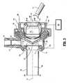
FIG. 1 is a perspective view of a surgical trocar assembly in accordance with the principles of the present disclosure including a cannula and an obturator assembled within the cannula;FIG. 2 is a perspective view of the surgical trocar assembly ofFIG. 1 illustrating the cannula and the obturator removed from the cannula; andFIG. 3 is a side cross-sectional view of the cannula of the surgical trocar assembly ofFIG. 1 .- The portal apparatus contemplates the introduction and manipulation of various types of instrumentation. Examples of instrumentation include clip appliers, graspers, dissectors, retractors, staplers, laser probes, photographic devices, endoscopes and laparoscopes, tubes and the like. Such instruments will be collectively referred to herein as "instruments or instrumentation". In many instances, these instruments incorporate ferromagnetic material such as stainless steel and titanium, particularly, within the end effector area, which would inherently cause at least the end effector area of the respective instrument to be attracted to magnetically charged elements. In this regard, and in accordance with the present disclosure, the portal apparatus incorporates a magnetically charged material or portion which may facilitate introduction and/or advancement of the instrument within and through the portal apparatus.
- In the following description, as is traditional, the term "proximal" refers to the portion of the instrument closest to the operator while the term "distal" refers to the portion of the instrument remote from the operator.
- Referring now to the drawings, in which like reference numerals identify identical or substantially similar parts throughout the several views,
FIGS. 1-2 illustrate theportal apparatus 10 of the present disclosure.Portal apparatus 10 may be in the form of a trocar assembly includingcannula assembly 100 andobturator assembly 200 which is positionable within thecannula assembly 100. For example, in one embodiment,portal apparatus 10 is a laparoscopic trocar assembly particularly adapted for use in laparoscopic surgery where the peritoneal cavity is insulated with a suitable gas, e.g., CO2, to raise the cavity wall from the internal organs therein. Specifically,cannula assembly 100 withobturator assembly 200 positioned therein is applied against the body cavity or abdominal wall. Onceobturator assembly 200 penetrates through the abdominal wall, theobturator assembly 200 is removed from thecannula assembly 100 to permit introduction of surgical instrumentation through theremaining cannula assembly 100 to perform the procedure. - Referring now to
FIGS. 1-2 , in conjunction withFIG. 3 ,cannula assembly 100 includescannula sleeve 102 andcannula housing 104 mounted to an end of thesleeve 102. Any means for mountingcannula sleeve 102 to cannulahousing 104 are envisioned including threaded arrangements, bayonet coupling, snap-fit arrangements, adhesives, etc. Cannula sleeve 102 and cannulahousing 104 may be integrally formed. Cannulasleeve 102 defines a longitudinal axis "a" extending along the length ofsleeve 102.Sleeve 102 further defines an internallongitudinal passage 106 dimensioned to permit passage of surgical instrumentation.Sleeve 102 definescollar 108 which is mounted tocannula housing 102 and an innertapered wall 110 adjacent thecollar 108. The sloped configuration oftapered wall 110 may assist in guiding then inserted instrument intolongitudinal passage 106.Sleeve 102 may be formed of stainless steel or other rigid materials such as a polymeric material or the like.Sleeve 102 may be clear or opaque. The diameter ofsleeve 102 may vary, but, typically ranges from about 10 mm to about 15 mm. - Cannula
housing 104 includes port opening 114 and luer fitting 116 positioned within the port opening 114.Luer fitting 116 is adapted for connection to a supply of insufflation gaseous is conventional in the art and incorporates valve 118 (FIGS. 1-2 ) to selectively open and close the passage of theluer fitting 116. Cannulahousing 104 further includes duckbill or zeroclosure valve 120 which tapers distally and inwardly to a sealed configuration.Closure valve 120 definesslit 122 which opens to permit passage of the surgical instrumentation and closes in the absence of the instrumentation.Closure valve 120 is preferably adapted to close upon exposure to the forces exerted by the insufflation gases in the internal cavity. Other zero closure valves are also contemplated including single or multiple slit valve arrangements, trumpet valves, flapper valves, etc.Closure valve 120 rests uponinternal shelf 124 ofcannula housing 104 when assembled. Obturator assembly 200 includesobturator housing 202 andelongated obturator 204 extending from theobturator housing 202. Elongatedobturator 204 may include penetratingtip 206 dimensioned to pierce, penetrate or incise tissue. Penetratingtip 206 may be bladed, pyramidal in shape or blunt.Portal apparatus 10 may also incorporateseal assembly 300.Seal assembly 300 may be a separate component fromcannula assembly 100 and, accordingly, adapted for releasable connection to thecannula assembly 100. Alternatively,seal assembly 300 may be incorporated as part ofcannula assembly 100.Seal assembly 300 includes a seal housing, generally identified asreference numeral 302, andgimbal mount 304 which is disposed within theseal housing 302.Seal housing 302 houses the sealing components of the assembly and defines the outer valve or seal body of theseal assembly 300.Seal housing 302 defines central seal housing axis "b" which is preferably parallel to the axis "a" ofcannula sleeve 102 and, more specifically, coincident with the axis "a" of thecannula sleeve 102.Seal housing 302 may incorporate multiple housing components, or may be a single unit.Seal housing 302 definesinner guide wall 308 andouter wall 310 disposed radially outwardly of theinner guide wall 308.Inner guide wall 308 definescentral passage 312 which is dimensioned to receive a surgical instrument and laterally confine the instrument withinseal housing 302.Inner guide wall 308 defines sloped or taperedportion 314 adjacent its proximal end.Sloped portion 314 is obliquely arranged relative to seal housing axis "b" and extends radially inwardly relative to the seal housing axis "b" in the distal direction.Sloped portion 314 assists in guiding the inserted instrument intocentral passage 312, particularly, when the instrument is non-aligned or off-axis relative to the seal housing axis "b", or introduced at an angle relative to the seal housing axis "b".Sloped portion 314 provides more flexibility to the surgeon by removing the necessity that the instrument be substantially aligned with the seal housing axis "b" upon insertion.Gimbal mount 304 is mounted in a manner to permit angulation and/or rotational movement of thegimbal mount 304 relative to, or about, seal housing axis "b". Specifically,gimbal mount 304 is free to angulate relative to seal housing axis "b" through a range of motion withinseal housing 302. Further details ofgimbal mount 304 may be ascertained by reference to commonly assignedU.S. Patent Publication No. 2006/0224120 to Smith .- Referring now to
FIG. 3 , the aspects of the ferromagnetic capabilities oftrocar assembly 10 and the features provided thereby in guiding and facilitating introduction and passage of instrumentation will be discussed. In one embodiment, sealhousing 302 includes magneticallyactive member 316 adjacent slopedportion 314 to attract a magnetically responsive object such as, for example, the tip of a medical instrument "i." In one embodiment, magneticallyactive member 316 is a coiled or annular arrangement disposed on the surface of slopedportion 314 or embedded therewithin, and extending a predetermined distance along the seal axis "b". The annular arrangement of magneticallyactive member 316 provides a magnetic force (indicated by arrows 318) which is sufficient to urge a magnetically responsive object, such as, for example, the tip of medical instrument "i", in general alignment with axes "a" and "b", intocentral passage 312 and distally along the longitudinal axis "a". In this manner, a surgeon need only position medical instrument "i" within the proximity ofcentral passage 312. Thereafter, surgical instrument "i" is aligned via themagnetic forces 318 and advanced throughcentral passage 312 andcannula sleeve 102. Moreover, the surgeon may advance surgical instrument "i" throughcannula assembly 100 with one hand without having to steadycannula assembly 100 with the other hand as is typically necessary to facilitate alignment of instrumentation with the passageway to the surgical site. - As a further alternative,
cannula assembly 100 includes a second magnetically active member distal of the first mentioned magneticallyactive member 316. In one embodiment,collar 108 ofcannula sleeve 102 incorporates magneticallyactive member 112 disposed on the surface or embedded within thecollar 108. Magneticallyactive member 112 defines a magnetic field creating a magnetic force (as indicated by directional arrows 114) along the longitudinal axis "a" in a general distal direction. This magnetic field assists in attracting and passing the instrument "i" along the longitudinal axis "b" throughsleeve 102 and also into central alignment with the longitudinal axis "a". It is envisioned that magneticallyactive member 112 may be embedded withincannula housing 104. - Magnetically
active members active members electromagnetic generator 400 is provided and in electrical communication with the magneticallyactive members - In use, an instument is positioned adjacent the
portal apparatus 10 and advanced throughcannula sleeve 102 as facilitated by either or both magneticallyactive members cannula sleeve 102, i.e., be retained with thecannula sleeve 102, through the created magnetic fields. - It will be understood that various modifications may be made to the embodiments disclosed herein. Therefore, the above description should not be construed as limiting, but merely as exemplifications of preferred embodiments. Those skilled in the art will envision other modifications within the scope of the claims appended hereto.
Claims (9)
- A surgical portal apparatus (10) for receiving medical instrumentation, which comprises:a portal member (300) including a housing (302) and a sleeve (102) extending from the housing adapted for passage through tissue for providing access to an underlying tissue site, the portal member defining a longitudinal axis, and proximal and distal ends, and having a longitudinal opening (312) extending through the proximal and distal ends, the portal member having a magnetic material (314) being disposed within the housing for creating a magnetic field adapted to urge instrumentation incorporating ferromagnetic material at least toward the longitudinal opening to permit passage therethrough and use of the instrumentation in performing a medical procedure adjacent the tissue site, andcharacterised in that the portal member comprises a second magnetic material (112) distal of the first magnetic material.
- The surgical portal apparatus (10) according to claim 1 wherein the magnetic material (314) is at least partially disposed within an interior surface of the housing (302).
- The surgical portal apparatus (10) according to claim 2 wherein the interior surface containing the magnetic material (314) at least partially defines the longitudinal opening (312).
- The surgical portal apparatus (10) according to claim 3 wherein the magnetic material (314) is coaxially arranged about the longitudinal axis ("b").
- The surgical portal apparatus (10) according to claim 4 wherein the interior surface defines a tapered arrangement relative to the longitudinal axis ("b").
- The surgical portal apparatus (10) according to claim 1 wherein the second magnetic material (112) is disposed within the portal sleeve (102).
- The surgical portal apparatus (10) according to claim 1 wherein the portal member (300) includes an electromagnet.
- The surgical portal apparatus (10) according to claim 7 wherein the electromagnet defines a coiled arrangement.
- The surgical portal apparatus (10) according to Claim 1, wherein the portal sleeve (102) defines a longitudinal axis ("a") and has a longitudinal opening (106) extending through the proximal and distal ends.
Applications Claiming Priority (2)
| Application Number | Priority Date | Filing Date | Title |
|---|---|---|---|
| US87848407P | 2007-01-03 | 2007-01-03 | |
| PCT/US2008/000162WO2008085919A2 (en) | 2007-01-03 | 2008-01-03 | Surgical system having a magnetic entry |
Publications (3)
| Publication Number | Publication Date |
|---|---|
| EP2114511A2 EP2114511A2 (en) | 2009-11-11 |
| EP2114511A4 EP2114511A4 (en) | 2013-01-02 |
| EP2114511B1true EP2114511B1 (en) | 2013-10-30 |
Family
ID=39609270
Family Applications (1)
| Application Number | Title | Priority Date | Filing Date |
|---|---|---|---|
| EP08705503.4ANot-in-forceEP2114511B1 (en) | 2007-01-03 | 2008-01-03 | Surgical system having a magnetic entry |
Country Status (6)
| Country | Link |
|---|---|
| US (1) | US8057438B2 (en) |
| EP (1) | EP2114511B1 (en) |
| JP (1) | JP5154575B2 (en) |
| AU (1) | AU2008205335B2 (en) |
| CA (1) | CA2672621A1 (en) |
| WO (1) | WO2008085919A2 (en) |
Families Citing this family (43)
| Publication number | Priority date | Publication date | Assignee | Title |
|---|---|---|---|---|
| US8784336B2 (en) | 2005-08-24 | 2014-07-22 | C. R. Bard, Inc. | Stylet apparatuses and methods of manufacture |
| US8388546B2 (en) | 2006-10-23 | 2013-03-05 | Bard Access Systems, Inc. | Method of locating the tip of a central venous catheter |
| US7794407B2 (en) | 2006-10-23 | 2010-09-14 | Bard Access Systems, Inc. | Method of locating the tip of a central venous catheter |
| US10449330B2 (en) | 2007-11-26 | 2019-10-22 | C. R. Bard, Inc. | Magnetic element-equipped needle assemblies |
| US10524691B2 (en) | 2007-11-26 | 2020-01-07 | C. R. Bard, Inc. | Needle assembly including an aligned magnetic element |
| US9649048B2 (en) | 2007-11-26 | 2017-05-16 | C. R. Bard, Inc. | Systems and methods for breaching a sterile field for intravascular placement of a catheter |
| US8781555B2 (en) | 2007-11-26 | 2014-07-15 | C. R. Bard, Inc. | System for placement of a catheter including a signal-generating stylet |
| ES2465915T3 (en) | 2007-11-26 | 2014-06-09 | C.R. Bard, Inc. | Integrated system for intravascular catheter placement |
| US9521961B2 (en) | 2007-11-26 | 2016-12-20 | C. R. Bard, Inc. | Systems and methods for guiding a medical instrument |
| US10751509B2 (en) | 2007-11-26 | 2020-08-25 | C. R. Bard, Inc. | Iconic representations for guidance of an indwelling medical device |
| US9636031B2 (en) | 2007-11-26 | 2017-05-02 | C.R. Bard, Inc. | Stylets for use with apparatus for intravascular placement of a catheter |
| CA2706860C (en) | 2007-11-26 | 2017-08-01 | Eastern Virginia Medical School | Magnaretractor system and method |
| US8849382B2 (en) | 2007-11-26 | 2014-09-30 | C. R. Bard, Inc. | Apparatus and display methods relating to intravascular placement of a catheter |
| US9901714B2 (en) | 2008-08-22 | 2018-02-27 | C. R. Bard, Inc. | Catheter assembly including ECG sensor and magnetic assemblies |
| US8437833B2 (en) | 2008-10-07 | 2013-05-07 | Bard Access Systems, Inc. | Percutaneous magnetic gastrostomy |
| USD626648S1 (en)* | 2008-10-29 | 2010-11-02 | Astra Tech Ab | Catheter sleeve |
| BRPI0917035A2 (en) | 2008-12-04 | 2019-09-24 | Pivot Medical Inc | "telescope access cannula, telescope shutter, system, method for providing an access corridor from a first off-site location to a second on-site location" |
| US9532724B2 (en) | 2009-06-12 | 2017-01-03 | Bard Access Systems, Inc. | Apparatus and method for catheter navigation using endovascular energy mapping |
| JP5795576B2 (en) | 2009-06-12 | 2015-10-14 | バード・アクセス・システムズ,インコーポレーテッド | Method of operating a computer-based medical device that uses an electrocardiogram (ECG) signal to position an intravascular device in or near the heart |
| EP2464407A4 (en) | 2009-08-10 | 2014-04-02 | Bard Access Systems Inc | Devices and methods for endovascular electrography |
| US10123821B2 (en)* | 2009-09-10 | 2018-11-13 | Atricure, Inc. | Scope and magnetic introducer systems and methods |
| JP5775881B2 (en) | 2010-01-15 | 2015-09-09 | イマージョン コーポレーションImmersion Corporation | System and method for minimally invasive surgical tools with tactile feedback |
| WO2011097312A1 (en) | 2010-02-02 | 2011-08-11 | C.R. Bard, Inc. | Apparatus and method for catheter navigation and tip location |
| EP4122385A1 (en) | 2010-05-28 | 2023-01-25 | C. R. Bard, Inc. | Insertion guidance system for needles and medical components |
| EP2912999B1 (en) | 2010-05-28 | 2022-06-29 | C. R. Bard, Inc. | Apparatus for use with needle insertion guidance system |
| BR112013002431B1 (en) | 2010-08-20 | 2021-06-29 | C.R. Bard, Inc | SYSTEM FOR RECONFIRMING THE POSITION OF A CATHETER INSIDE A PATIENT |
| US8801693B2 (en) | 2010-10-29 | 2014-08-12 | C. R. Bard, Inc. | Bioimpedance-assisted placement of a medical device |
| RU2609203C2 (en) | 2011-07-06 | 2017-01-30 | Си.Ар. Бард, Инк. | Determination and calibration of needle length for needle guidance system |
| US20130102967A1 (en)* | 2011-10-21 | 2013-04-25 | Synergetics, Inc. | Magnetic Trocar System |
| EP2846713A1 (en)* | 2012-05-09 | 2015-03-18 | EON Surgical Ltd. | Laparoscopic port |
| RU2669621C2 (en)* | 2012-09-28 | 2018-10-12 | Си. Ар. БАРД, ИНК. | Needle assembly including an aligned magnetic element |
| US8764769B1 (en) | 2013-03-12 | 2014-07-01 | Levita Magnetics International Corp. | Grasper with magnetically-controlled positioning |
| WO2015112645A1 (en) | 2014-01-21 | 2015-07-30 | Levita Magnetics International Corp. | Laparoscopic graspers and systems therefor |
| WO2015120256A2 (en) | 2014-02-06 | 2015-08-13 | C.R. Bard, Inc. | Systems and methods for guidance and placement of an intravascular device |
| US10973584B2 (en) | 2015-01-19 | 2021-04-13 | Bard Access Systems, Inc. | Device and method for vascular access |
| WO2016135945A1 (en)* | 2015-02-27 | 2016-09-01 | オリンパス株式会社 | Medical power supply system |
| ES2895900T3 (en) | 2015-04-13 | 2022-02-23 | Levita Magnetics Int Corp | Magnetically controlled location handle |
| WO2016168377A1 (en) | 2015-04-13 | 2016-10-20 | Levita Magnetics International Corp. | Retractor systems, devices, and methods for use |
| WO2016210325A1 (en) | 2015-06-26 | 2016-12-29 | C.R. Bard, Inc. | Connector interface for ecg-based catheter positioning system |
| EP3399902B1 (en) | 2016-01-08 | 2024-06-12 | Levita Magnetics International Corp. | One-operator surgical system |
| US11000207B2 (en) | 2016-01-29 | 2021-05-11 | C. R. Bard, Inc. | Multiple coil system for tracking a medical device |
| US11020137B2 (en) | 2017-03-20 | 2021-06-01 | Levita Magnetics International Corp. | Directable traction systems and methods |
| US10992079B2 (en) | 2018-10-16 | 2021-04-27 | Bard Access Systems, Inc. | Safety-equipped connection systems and methods thereof for establishing electrical connections |
Family Cites Families (12)
| Publication number | Priority date | Publication date | Assignee | Title |
|---|---|---|---|---|
| US2949931A (en)* | 1958-01-29 | 1960-08-23 | Hughes Aircraft Co | Magnetic check valve |
| JPS5830721A (en)* | 1981-08-17 | 1983-02-23 | Olympus Optical Co Ltd | Fixing device for insertion part of industrial endoscope |
| US4535773A (en)* | 1982-03-26 | 1985-08-20 | Inbae Yoon | Safety puncturing instrument and method |
| US5036866A (en)* | 1988-03-09 | 1991-08-06 | Devon Industries, Inc. | Surgical instrument retainer |
| DE59207776D1 (en)* | 1991-10-31 | 1997-02-06 | Helmut Laser | LOCKING SYSTEM FOR AN INSTRUMENT PASSAGE |
| US5540648A (en)* | 1992-08-17 | 1996-07-30 | Yoon; Inbae | Medical instrument stabilizer with anchoring system and methods |
| US5573545A (en)* | 1993-06-24 | 1996-11-12 | Yoon; Inbae | Safety penetrating instrument with safety member and cannula moving during penetration and triggered cannula and/or safety member protrusion |
| US5989224A (en)* | 1998-02-23 | 1999-11-23 | Dexide Corporation | Universal seal for use with endoscopic cannula |
| AU2004291066C1 (en)* | 2003-11-12 | 2011-08-04 | Van Lue Veterinary Surgical, Llc | Trocars and trocar assemblies |
| US20050165272A1 (en)* | 2003-12-01 | 2005-07-28 | Yuta Okada | Endoscope system |
| US7582071B2 (en)* | 2005-03-28 | 2009-09-01 | Tyco Healthcare Group Lp | Introducer seal assembly |
| US7896845B2 (en)* | 2008-06-26 | 2011-03-01 | Tyco Healthcare Group Lp | Surgical portal assembly |
- 2008
- 2008-01-03CACA002672621Apatent/CA2672621A1/ennot_activeAbandoned
- 2008-01-03WOPCT/US2008/000162patent/WO2008085919A2/enactiveApplication Filing
- 2008-01-03JPJP2009544940Apatent/JP5154575B2/ennot_activeExpired - Fee Related
- 2008-01-03USUS12/517,390patent/US8057438B2/ennot_activeExpired - Fee Related
- 2008-01-03AUAU2008205335Apatent/AU2008205335B2/ennot_activeCeased
- 2008-01-03EPEP08705503.4Apatent/EP2114511B1/ennot_activeNot-in-force
Also Published As
| Publication number | Publication date |
|---|---|
| EP2114511A4 (en) | 2013-01-02 |
| EP2114511A2 (en) | 2009-11-11 |
| WO2008085919A2 (en) | 2008-07-17 |
| JP2010514540A (en) | 2010-05-06 |
| AU2008205335A1 (en) | 2008-07-17 |
| JP5154575B2 (en) | 2013-02-27 |
| US8057438B2 (en) | 2011-11-15 |
| US20100010444A1 (en) | 2010-01-14 |
| CA2672621A1 (en) | 2008-07-17 |
| AU2008205335B2 (en) | 2013-07-25 |
| WO2008085919A3 (en) | 2008-09-25 |
Similar Documents
| Publication | Publication Date | Title |
|---|---|---|
| EP2114511B1 (en) | Surgical system having a magnetic entry | |
| JP5281859B2 (en) | Seal assembly for a surgical access device | |
| CA2539683C (en) | Surgical portal with enhanced retention capabilities | |
| US20150112280A1 (en) | Surgical seal assembly | |
| EP1994898B1 (en) | Surgical portal apparatus with armature assembly | |
| CA2551255A1 (en) | Beveled access apparatus with locking ribs elements | |
| JP5607778B2 (en) | Surgical seal assembly | |
| EP2138114B1 (en) | Surgical portal assembly | |
| EP2248476A1 (en) | Ring and seal for trocar | |
| EP2368505A1 (en) | Portal apparatus with a tubular seal device |
Legal Events
| Date | Code | Title | Description |
|---|---|---|---|
| PUAI | Public reference made under article 153(3) epc to a published international application that has entered the european phase | Free format text:ORIGINAL CODE: 0009012 | |
| 17P | Request for examination filed | Effective date:20090803 | |
| AK | Designated contracting states | Kind code of ref document:A2 Designated state(s):AT BE BG CH CY CZ DE DK EE ES FI FR GB GR HR HU IE IS IT LI LT LU LV MC MT NL NO PL PT RO SE SI SK TR | |
| DAX | Request for extension of the european patent (deleted) | ||
| RAP1 | Party data changed (applicant data changed or rights of an application transferred) | Owner name:COVIDIEN LP | |
| A4 | Supplementary search report drawn up and despatched | Effective date:20121205 | |
| RIC1 | Information provided on ipc code assigned before grant | Ipc:A61M 39/04 20060101AFI20121129BHEP Ipc:A61B 17/34 20060101ALI20121129BHEP | |
| GRAP | Despatch of communication of intention to grant a patent | Free format text:ORIGINAL CODE: EPIDOSNIGR1 | |
| INTG | Intention to grant announced | Effective date:20130813 | |
| GRAS | Grant fee paid | Free format text:ORIGINAL CODE: EPIDOSNIGR3 | |
| GRAA | (expected) grant | Free format text:ORIGINAL CODE: 0009210 | |
| AK | Designated contracting states | Kind code of ref document:B1 Designated state(s):AT BE BG CH CY CZ DE DK EE ES FI FR GB GR HR HU IE IS IT LI LT LU LV MC MT NL NO PL PT RO SE SI SK TR | |
| REG | Reference to a national code | Ref country code:GB Ref legal event code:FG4D | |
| REG | Reference to a national code | Ref country code:CH Ref legal event code:EP | |
| REG | Reference to a national code | Ref country code:AT Ref legal event code:REF Ref document number:638274 Country of ref document:AT Kind code of ref document:T Effective date:20131115 | |
| REG | Reference to a national code | Ref country code:IE Ref legal event code:FG4D | |
| REG | Reference to a national code | Ref country code:DE Ref legal event code:R096 Ref document number:602008028415 Country of ref document:DE Effective date:20131224 | |
| REG | Reference to a national code | Ref country code:NL Ref legal event code:VDEP Effective date:20131030 | |
| REG | Reference to a national code | Ref country code:AT Ref legal event code:MK05 Ref document number:638274 Country of ref document:AT Kind code of ref document:T Effective date:20131030 | |
| REG | Reference to a national code | Ref country code:LT Ref legal event code:MG4D | |
| PG25 | Lapsed in a contracting state [announced via postgrant information from national office to epo] | Ref country code:LT Free format text:LAPSE BECAUSE OF FAILURE TO SUBMIT A TRANSLATION OF THE DESCRIPTION OR TO PAY THE FEE WITHIN THE PRESCRIBED TIME-LIMIT Effective date:20131030 Ref country code:SE Free format text:LAPSE BECAUSE OF FAILURE TO SUBMIT A TRANSLATION OF THE DESCRIPTION OR TO PAY THE FEE WITHIN THE PRESCRIBED TIME-LIMIT Effective date:20131030 Ref country code:FI Free format text:LAPSE BECAUSE OF FAILURE TO SUBMIT A TRANSLATION OF THE DESCRIPTION OR TO PAY THE FEE WITHIN THE PRESCRIBED TIME-LIMIT Effective date:20131030 Ref country code:HR Free format text:LAPSE BECAUSE OF FAILURE TO SUBMIT A TRANSLATION OF THE DESCRIPTION OR TO PAY THE FEE WITHIN THE PRESCRIBED TIME-LIMIT Effective date:20131030 Ref country code:IS Free format text:LAPSE BECAUSE OF FAILURE TO SUBMIT A TRANSLATION OF THE DESCRIPTION OR TO PAY THE FEE WITHIN THE PRESCRIBED TIME-LIMIT Effective date:20140228 Ref country code:NL Free format text:LAPSE BECAUSE OF FAILURE TO SUBMIT A TRANSLATION OF THE DESCRIPTION OR TO PAY THE FEE WITHIN THE PRESCRIBED TIME-LIMIT Effective date:20131030 Ref country code:BE Free format text:LAPSE BECAUSE OF FAILURE TO SUBMIT A TRANSLATION OF THE DESCRIPTION OR TO PAY THE FEE WITHIN THE PRESCRIBED TIME-LIMIT Effective date:20131030 Ref country code:NO Free format text:LAPSE BECAUSE OF FAILURE TO SUBMIT A TRANSLATION OF THE DESCRIPTION OR TO PAY THE FEE WITHIN THE PRESCRIBED TIME-LIMIT Effective date:20140130 | |
| PGFP | Annual fee paid to national office [announced via postgrant information from national office to epo] | Ref country code:IE Payment date:20140127 Year of fee payment:7 Ref country code:DE Payment date:20140129 Year of fee payment:7 | |
| PG25 | Lapsed in a contracting state [announced via postgrant information from national office to epo] | Ref country code:AT Free format text:LAPSE BECAUSE OF FAILURE TO SUBMIT A TRANSLATION OF THE DESCRIPTION OR TO PAY THE FEE WITHIN THE PRESCRIBED TIME-LIMIT Effective date:20131030 Ref country code:ES Free format text:LAPSE BECAUSE OF FAILURE TO SUBMIT A TRANSLATION OF THE DESCRIPTION OR TO PAY THE FEE WITHIN THE PRESCRIBED TIME-LIMIT Effective date:20131030 Ref country code:LV Free format text:LAPSE BECAUSE OF FAILURE TO SUBMIT A TRANSLATION OF THE DESCRIPTION OR TO PAY THE FEE WITHIN THE PRESCRIBED TIME-LIMIT Effective date:20131030 Ref country code:CY Free format text:LAPSE BECAUSE OF FAILURE TO SUBMIT A TRANSLATION OF THE DESCRIPTION OR TO PAY THE FEE WITHIN THE PRESCRIBED TIME-LIMIT Effective date:20131030 | |
| PGFP | Annual fee paid to national office [announced via postgrant information from national office to epo] | Ref country code:FR Payment date:20140117 Year of fee payment:7 | |
| PG25 | Lapsed in a contracting state [announced via postgrant information from national office to epo] | Ref country code:PT Free format text:LAPSE BECAUSE OF FAILURE TO SUBMIT A TRANSLATION OF THE DESCRIPTION OR TO PAY THE FEE WITHIN THE PRESCRIBED TIME-LIMIT Effective date:20140228 | |
| PGFP | Annual fee paid to national office [announced via postgrant information from national office to epo] | Ref country code:GB Payment date:20140127 Year of fee payment:7 | |
| PG25 | Lapsed in a contracting state [announced via postgrant information from national office to epo] | Ref country code:EE Free format text:LAPSE BECAUSE OF FAILURE TO SUBMIT A TRANSLATION OF THE DESCRIPTION OR TO PAY THE FEE WITHIN THE PRESCRIBED TIME-LIMIT Effective date:20131030 | |
| REG | Reference to a national code | Ref country code:DE Ref legal event code:R097 Ref document number:602008028415 Country of ref document:DE | |
| PG25 | Lapsed in a contracting state [announced via postgrant information from national office to epo] | Ref country code:IT Free format text:LAPSE BECAUSE OF FAILURE TO SUBMIT A TRANSLATION OF THE DESCRIPTION OR TO PAY THE FEE WITHIN THE PRESCRIBED TIME-LIMIT Effective date:20131030 Ref country code:SK Free format text:LAPSE BECAUSE OF FAILURE TO SUBMIT A TRANSLATION OF THE DESCRIPTION OR TO PAY THE FEE WITHIN THE PRESCRIBED TIME-LIMIT Effective date:20131030 Ref country code:MC Free format text:LAPSE BECAUSE OF FAILURE TO SUBMIT A TRANSLATION OF THE DESCRIPTION OR TO PAY THE FEE WITHIN THE PRESCRIBED TIME-LIMIT Effective date:20131030 Ref country code:PL Free format text:LAPSE BECAUSE OF FAILURE TO SUBMIT A TRANSLATION OF THE DESCRIPTION OR TO PAY THE FEE WITHIN THE PRESCRIBED TIME-LIMIT Effective date:20131030 Ref country code:CZ Free format text:LAPSE BECAUSE OF FAILURE TO SUBMIT A TRANSLATION OF THE DESCRIPTION OR TO PAY THE FEE WITHIN THE PRESCRIBED TIME-LIMIT Effective date:20131030 Ref country code:LU Free format text:LAPSE BECAUSE OF FAILURE TO SUBMIT A TRANSLATION OF THE DESCRIPTION OR TO PAY THE FEE WITHIN THE PRESCRIBED TIME-LIMIT Effective date:20140103 Ref country code:RO Free format text:LAPSE BECAUSE OF FAILURE TO SUBMIT A TRANSLATION OF THE DESCRIPTION OR TO PAY THE FEE WITHIN THE PRESCRIBED TIME-LIMIT Effective date:20131030 | |
| REG | Reference to a national code | Ref country code:CH Ref legal event code:PL | |
| PLBE | No opposition filed within time limit | Free format text:ORIGINAL CODE: 0009261 | |
| STAA | Information on the status of an ep patent application or granted ep patent | Free format text:STATUS: NO OPPOSITION FILED WITHIN TIME LIMIT | |
| PG25 | Lapsed in a contracting state [announced via postgrant information from national office to epo] | Ref country code:DK Free format text:LAPSE BECAUSE OF FAILURE TO SUBMIT A TRANSLATION OF THE DESCRIPTION OR TO PAY THE FEE WITHIN THE PRESCRIBED TIME-LIMIT Effective date:20131030 | |
| 26N | No opposition filed | Effective date:20140731 | |
| PG25 | Lapsed in a contracting state [announced via postgrant information from national office to epo] | Ref country code:LI Free format text:LAPSE BECAUSE OF NON-PAYMENT OF DUE FEES Effective date:20140131 Ref country code:CH Free format text:LAPSE BECAUSE OF NON-PAYMENT OF DUE FEES Effective date:20140131 | |
| REG | Reference to a national code | Ref country code:DE Ref legal event code:R097 Ref document number:602008028415 Country of ref document:DE Effective date:20140731 | |
| PG25 | Lapsed in a contracting state [announced via postgrant information from national office to epo] | Ref country code:SI Free format text:LAPSE BECAUSE OF FAILURE TO SUBMIT A TRANSLATION OF THE DESCRIPTION OR TO PAY THE FEE WITHIN THE PRESCRIBED TIME-LIMIT Effective date:20131030 | |
| REG | Reference to a national code | Ref country code:DE Ref legal event code:R119 Ref document number:602008028415 Country of ref document:DE | |
| GBPC | Gb: european patent ceased through non-payment of renewal fee | Effective date:20150103 | |
| PG25 | Lapsed in a contracting state [announced via postgrant information from national office to epo] | Ref country code:DE Free format text:LAPSE BECAUSE OF NON-PAYMENT OF DUE FEES Effective date:20150801 Ref country code:GB Free format text:LAPSE BECAUSE OF NON-PAYMENT OF DUE FEES Effective date:20150103 | |
| REG | Reference to a national code | Ref country code:FR Ref legal event code:ST Effective date:20150930 | |
| REG | Reference to a national code | Ref country code:IE Ref legal event code:MM4A | |
| PG25 | Lapsed in a contracting state [announced via postgrant information from national office to epo] | Ref country code:FR Free format text:LAPSE BECAUSE OF NON-PAYMENT OF DUE FEES Effective date:20150202 | |
| PG25 | Lapsed in a contracting state [announced via postgrant information from national office to epo] | Ref country code:IE Free format text:LAPSE BECAUSE OF NON-PAYMENT OF DUE FEES Effective date:20150103 | |
| PG25 | Lapsed in a contracting state [announced via postgrant information from national office to epo] | Ref country code:MT Free format text:LAPSE BECAUSE OF FAILURE TO SUBMIT A TRANSLATION OF THE DESCRIPTION OR TO PAY THE FEE WITHIN THE PRESCRIBED TIME-LIMIT Effective date:20131030 | |
| PG25 | Lapsed in a contracting state [announced via postgrant information from national office to epo] | Ref country code:BG Free format text:LAPSE BECAUSE OF FAILURE TO SUBMIT A TRANSLATION OF THE DESCRIPTION OR TO PAY THE FEE WITHIN THE PRESCRIBED TIME-LIMIT Effective date:20131030 | |
| PG25 | Lapsed in a contracting state [announced via postgrant information from national office to epo] | Ref country code:GR Free format text:LAPSE BECAUSE OF FAILURE TO SUBMIT A TRANSLATION OF THE DESCRIPTION OR TO PAY THE FEE WITHIN THE PRESCRIBED TIME-LIMIT Effective date:20140131 | |
| PG25 | Lapsed in a contracting state [announced via postgrant information from national office to epo] | Ref country code:HU Free format text:LAPSE BECAUSE OF FAILURE TO SUBMIT A TRANSLATION OF THE DESCRIPTION OR TO PAY THE FEE WITHIN THE PRESCRIBED TIME-LIMIT; INVALID AB INITIO Effective date:20080103 Ref country code:TR Free format text:LAPSE BECAUSE OF FAILURE TO SUBMIT A TRANSLATION OF THE DESCRIPTION OR TO PAY THE FEE WITHIN THE PRESCRIBED TIME-LIMIT Effective date:20131030 |