EP2111793B1 - Device and method for containing a bodily fluid for analysis purposes - Google Patents
Device and method for containing a bodily fluid for analysis purposesDownload PDFInfo
- Publication number
- EP2111793B1 EP2111793B1EP08169933.2AEP08169933AEP2111793B1EP 2111793 B1EP2111793 B1EP 2111793B1EP 08169933 AEP08169933 AEP 08169933AEP 2111793 B1EP2111793 B1EP 2111793B1
- Authority
- EP
- European Patent Office
- Prior art keywords
- sample receiving
- receiving unit
- unit
- plunger
- lancing
- Prior art date
- Legal status (The legal status is an assumption and is not a legal conclusion. Google has not performed a legal analysis and makes no representation as to the accuracy of the status listed.)
- Expired - Lifetime
Links
Images


Classifications
- A—HUMAN NECESSITIES
- A61—MEDICAL OR VETERINARY SCIENCE; HYGIENE
- A61B—DIAGNOSIS; SURGERY; IDENTIFICATION
- A61B5/00—Measuring for diagnostic purposes; Identification of persons
- A61B5/14—Devices for taking samples of blood ; Measuring characteristics of blood in vivo, e.g. gas concentration within the blood, pH-value of blood
- A61B5/1405—Devices for taking blood samples
- A—HUMAN NECESSITIES
- A61—MEDICAL OR VETERINARY SCIENCE; HYGIENE
- A61B—DIAGNOSIS; SURGERY; IDENTIFICATION
- A61B5/00—Measuring for diagnostic purposes; Identification of persons
- A61B5/15—Devices for taking samples of blood
- A61B5/151—Devices specially adapted for taking samples of capillary blood, e.g. by lancets, needles or blades
- A61B5/15146—Devices loaded with multiple lancets simultaneously, e.g. for serial firing without reloading, for example by use of stocking means.
- A—HUMAN NECESSITIES
- A61—MEDICAL OR VETERINARY SCIENCE; HYGIENE
- A61B—DIAGNOSIS; SURGERY; IDENTIFICATION
- A61B5/00—Measuring for diagnostic purposes; Identification of persons
- A61B5/15—Devices for taking samples of blood
- A61B5/150007—Details
- A61B5/150015—Source of blood
- A61B5/150022—Source of blood for capillary blood or interstitial fluid
- A—HUMAN NECESSITIES
- A61—MEDICAL OR VETERINARY SCIENCE; HYGIENE
- A61B—DIAGNOSIS; SURGERY; IDENTIFICATION
- A61B5/00—Measuring for diagnostic purposes; Identification of persons
- A61B5/15—Devices for taking samples of blood
- A61B5/150007—Details
- A61B5/150358—Strips for collecting blood, e.g. absorbent
- A—HUMAN NECESSITIES
- A61—MEDICAL OR VETERINARY SCIENCE; HYGIENE
- A61B—DIAGNOSIS; SURGERY; IDENTIFICATION
- A61B5/00—Measuring for diagnostic purposes; Identification of persons
- A61B5/15—Devices for taking samples of blood
- A61B5/150007—Details
- A61B5/150374—Details of piercing elements or protective means for preventing accidental injuries by such piercing elements
- A61B5/150381—Design of piercing elements
- A61B5/150412—Pointed piercing elements, e.g. needles, lancets for piercing the skin
- A—HUMAN NECESSITIES
- A61—MEDICAL OR VETERINARY SCIENCE; HYGIENE
- A61B—DIAGNOSIS; SURGERY; IDENTIFICATION
- A61B5/00—Measuring for diagnostic purposes; Identification of persons
- A61B5/15—Devices for taking samples of blood
- A61B5/150007—Details
- A61B5/150374—Details of piercing elements or protective means for preventing accidental injuries by such piercing elements
- A61B5/150381—Design of piercing elements
- A61B5/150503—Single-ended needles
- A61B5/150519—Details of construction of hub, i.e. element used to attach the single-ended needle to a piercing device or sampling device
- A—HUMAN NECESSITIES
- A61—MEDICAL OR VETERINARY SCIENCE; HYGIENE
- A61B—DIAGNOSIS; SURGERY; IDENTIFICATION
- A61B5/00—Measuring for diagnostic purposes; Identification of persons
- A61B5/15—Devices for taking samples of blood
- A61B5/150007—Details
- A61B5/150374—Details of piercing elements or protective means for preventing accidental injuries by such piercing elements
- A61B5/150534—Design of protective means for piercing elements for preventing accidental needle sticks, e.g. shields, caps, protectors, axially extensible sleeves, pivotable protective sleeves
- A61B5/150572—Pierceable protectors, e.g. shields, caps, sleeves or films, e.g. for hygienic purposes
- A—HUMAN NECESSITIES
- A61—MEDICAL OR VETERINARY SCIENCE; HYGIENE
- A61B—DIAGNOSIS; SURGERY; IDENTIFICATION
- A61B5/00—Measuring for diagnostic purposes; Identification of persons
- A61B5/15—Devices for taking samples of blood
- A61B5/150007—Details
- A61B5/150374—Details of piercing elements or protective means for preventing accidental injuries by such piercing elements
- A61B5/150534—Design of protective means for piercing elements for preventing accidental needle sticks, e.g. shields, caps, protectors, axially extensible sleeves, pivotable protective sleeves
- A61B5/150633—Protective sleeves which are axially extensible, e.g. sleeves connected to, or integrated in, the piercing or driving device; pivotable protective sleeves
- A—HUMAN NECESSITIES
- A61—MEDICAL OR VETERINARY SCIENCE; HYGIENE
- A61B—DIAGNOSIS; SURGERY; IDENTIFICATION
- A61B5/00—Measuring for diagnostic purposes; Identification of persons
- A61B5/15—Devices for taking samples of blood
- A61B5/151—Devices specially adapted for taking samples of capillary blood, e.g. by lancets, needles or blades
- A61B5/15101—Details
- A61B5/15126—Means for controlling the lancing movement, e.g. 2D- or 3D-shaped elements, tooth-shaped elements or sliding guides
- A61B5/1513—Means for controlling the lancing movement, e.g. 2D- or 3D-shaped elements, tooth-shaped elements or sliding guides comprising linear sliding guides
- A—HUMAN NECESSITIES
- A61—MEDICAL OR VETERINARY SCIENCE; HYGIENE
- A61B—DIAGNOSIS; SURGERY; IDENTIFICATION
- A61B5/00—Measuring for diagnostic purposes; Identification of persons
- A61B5/15—Devices for taking samples of blood
- A61B5/151—Devices specially adapted for taking samples of capillary blood, e.g. by lancets, needles or blades
- A61B5/15146—Devices loaded with multiple lancets simultaneously, e.g. for serial firing without reloading, for example by use of stocking means.
- A61B5/15148—Constructional features of stocking means, e.g. strip, roll, disc, cartridge, belt or tube
- A61B5/15149—Arrangement of piercing elements relative to each other
- A61B5/15151—Each piercing element being stocked in a separate isolated compartment
- A—HUMAN NECESSITIES
- A61—MEDICAL OR VETERINARY SCIENCE; HYGIENE
- A61B—DIAGNOSIS; SURGERY; IDENTIFICATION
- A61B5/00—Measuring for diagnostic purposes; Identification of persons
- A61B5/15—Devices for taking samples of blood
- A61B5/151—Devices specially adapted for taking samples of capillary blood, e.g. by lancets, needles or blades
- A61B5/15146—Devices loaded with multiple lancets simultaneously, e.g. for serial firing without reloading, for example by use of stocking means.
- A61B5/15148—Constructional features of stocking means, e.g. strip, roll, disc, cartridge, belt or tube
- A61B5/15157—Geometry of stocking means or arrangement of piercing elements therein
- A61B5/15159—Piercing elements stocked in or on a disc
- A61B5/15161—Characterized by propelling the piercing element in a radial direction relative to the disc
- A—HUMAN NECESSITIES
- A61—MEDICAL OR VETERINARY SCIENCE; HYGIENE
- A61B—DIAGNOSIS; SURGERY; IDENTIFICATION
- A61B5/00—Measuring for diagnostic purposes; Identification of persons
- A61B5/15—Devices for taking samples of blood
- A61B5/151—Devices specially adapted for taking samples of capillary blood, e.g. by lancets, needles or blades
- A61B5/15146—Devices loaded with multiple lancets simultaneously, e.g. for serial firing without reloading, for example by use of stocking means.
- A61B5/15148—Constructional features of stocking means, e.g. strip, roll, disc, cartridge, belt or tube
- A61B5/15157—Geometry of stocking means or arrangement of piercing elements therein
- A61B5/15159—Piercing elements stocked in or on a disc
- A61B5/15163—Characterized by propelling the piercing element in an axial direction relative to the disc
- A—HUMAN NECESSITIES
- A61—MEDICAL OR VETERINARY SCIENCE; HYGIENE
- A61B—DIAGNOSIS; SURGERY; IDENTIFICATION
- A61B5/00—Measuring for diagnostic purposes; Identification of persons
- A61B5/15—Devices for taking samples of blood
- A61B5/151—Devices specially adapted for taking samples of capillary blood, e.g. by lancets, needles or blades
- A61B5/15146—Devices loaded with multiple lancets simultaneously, e.g. for serial firing without reloading, for example by use of stocking means.
- A61B5/15148—Constructional features of stocking means, e.g. strip, roll, disc, cartridge, belt or tube
- A61B5/15176—Stocking means comprising cap, cover, sheath or protection for aseptic stocking
Definitions
- the inventionrelates to a device for receiving a body fluid for analysis purposes according to the preamble of the independent claims.
- the coupling devicepreferably comprises automatically operating connection means for establishing and releasing a positive connection between the drive unit and sample receiving unit, wherein the drive unit and the sample receiving unit are separated from each other in a starting position.
- the coupling devicehas at least one in the outward and return movement path-dependent between a release position and an engagement position movable carrier for coupling drive unit and sample receiving unit.
- the coupling devicehas a control link which can be scanned during the forward and backward movement by the driver, in particular formed by a run-on slope of the guide chamber.
- the driveris arranged at a proximal end of the sample receiving unit and formed by at least one preferably in an inherent tension in an engaged position engageable holding claw.
- a mechanically particularly simple embodimentprovides that the drive unit has a plunger, and that the driver automatically engages with an axial feed of the plunger with a head portion of the plunger.
- the hook plungerhas a bent hook head, wherein the hook head protrudes laterally in the coupling to the sample receiving unit.
- a further improvementresults from the fact that the hook plunger can be pivoted relative to the sample receiving unit via a plunger piece, which starts obliquely against a guide contour during the forward and backward movement. It is advantageous if the hook plunger in a guide chamber upstream, is guided in the direction of the forward movement tapered guide cone, wherein the guide cone is offset eccentrically relative to the central axis of the guide chamber.
- the hook plungerhas a frontally shaped, pointing against the guide chamber spinous process.
- the robenamajiis releasably held by a projecting into the guide chamber clamping structure, wherein the clamping force of the clamping structure should be smaller than the maximum driving force of the drive unit. It is advantageous for a space-saving design, if the sample receiving unit has a releasing a passage cross-section of the guide chamber for engagement and / or notching of the hook plunger in the clamping structure elastically deformed proximal end portion.
- the drive unithas a control device.
- the sample receiving unitpreferably has stops for the lancing unit formed by projecting body edges.
- the sample receiving unitis preferably held on a slide which can be moved back and forth in the guide chamber by means of the drive unit via a latching connection.
- the sample receiving unithas a preferably capillary active transport channel for a possible automatic flow connection from the receiving site to an evaluation point, which may be formed by a special analytical test element for examining the body fluid to the sample receiving unit.
- the guide chamberis closed by a sealing film at least in the region of an ejection opening.
- the sample receiving unitshould have a pointing in the feed direction free end region for piercing the sealing film, so that damage to the lancing unit can be avoided.
- the sample receiving unitis designed as a test strip or preferably injection-molded test body, in particular for blood tests.
- the sample receiving unitis formed by a cannula, preferably also designed as a guide for the lancing unit, for sucking in the sample liquid.
- the inventionalso extends to an analysis device, in particular a portable handheld device for medical diagnosis, with a device according to the invention for receiving a body fluid.
- the in Fig. 2 Drive unit 20shown a double ram 64 for coupling the sample receiving unit 14 and the lancing unit 16. This is formed by an outer tappet 66 and a telescopic inner tappet 68 therein.
- the reciprocating motion transmissionvia via a respective positive connection of the driver 46, 62 of the coupling device 18, as will be explained in more detail below.
- the drum magazine 26can be rotated in a revolving manner to position the desired sample receiving unit 14 for drive coupling. Then, in a next step according to Fig. 3 the double plunger 64 is retracted by piercing the sealing foil 42 over the engagement opening 28 in the guide chamber 12 and brought in frontal attack against the driver 46, 62. After passing the run-up slope 77 passes accordingly Fig. 4
- the outer guide 46is supported by the broad sides 82 of the guide chamber 12, which are adapted as sliding surfaces to the outer contour of the sample receiving unit 14.
- the lancing processtakes place at a displacement fixed in its engaged position outer driver 46 by further feed of the inner plunger 68, wherein the inner driver 62 of the lancing unit 16 passes after passing the run-on slope 85 in its engaged position.
- the piercing depthis limited by the available displacement path up to the shown stop position of the inner driver 62, wherein the piercing speed should be as high as possible for a pain-free puncture.
- the retrieval of the lancet 52 and the sample receiving unit 14takes place in reverse sequence accordingly 4 to 2 .
- a microscopic amount (microliters) of escaping bloodis required, which automatically flows to the test field 56 via the capillary gap on the shell side of the lancet 52 by capillary action.
- the sample receiving unit 14Due to the existing in the return direction positive connection of the driver 46, 62, the sample receiving unit 14 can be completely withdrawn into the guide chamber 12 until finally the stop pieces 48 abut against the wall step 86 of the guide chamber 12 and the double plunger 64 is released again.
- the in Fig. 8 to 10 Sequence of sample recording shownbasically corresponds to the sequence Fig. 3 to 5 , One difference is that the outer plunger 66 abuts against the facing end edge of the test strip 88 only in abutment so as to facilitate piercing the sealing film 42 during advancement.
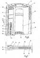
- the embodiment according to 15 to 17comprises a flat disk-shaped magazine 106 as a container 10, in which the guide chambers 12 extend radially in a star shape.
- cannulas 108are mounted so as to be radially displaceable as sample receiving units 14.
- the cannulas or sample tubes 108in turn form a guide for a separately displaceable lancet 52.
- the drive couplingtakes place by means of drivers 46, 62, which engage in the frontally open-edge guide chambers 12 by means of angular engagement members 110, 112 of the drive unit via axially parallel to the disc axis 109 20 consecutively in the in Fig. 12 shown front feed position are displaced.
- the collected bloodflows via the cannula 108 axially to the sleeve-shaped test field 56, whose response to an analyte via the dome-shaped window 114 can be detected optically.
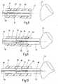
- the coupling device 18has a hook plunger 116 which can be coupled to the test strips 88 in a drum magazine 26 and which is driven at its proximal end 118 for a forward and backward movement.
- At its distal end of the hook plunger 116is provided with a bent over an elbow 119 hook head 120.
- Thishas accordingly Fig. 19 a against the back front end of a test strip 88 abutting shear edge 122 for the strip feed and einklinkbare in a recess 124 of the test strip 88 pull edge 126 for strip retrieval.
- the flanks 122, 126are inclined towards the free edge in the feed direction.
- a front end formed on the hook head 120 and pointing with its tip in the feed direction spinous process 127allows easy piercing of the guide chamber 12 tightly closing film.
- the hook plunger 116is mounted in a guide bushing 128 which can be aligned with the desired guide chamber via a drum or index wheel 132 provided with conical centering openings 130 on the end face of the drum magazine 26.
- the test strips 88are releasably held at their proximal end portion by a clamping structure 134 in their respective guide chamber 12.
- the clamping structure 134has two laterally spaced apart, projecting into the guide chamber 12 clamping cam 136, which cooperate with along the guide chamber 12 extending, outwardly offset guide ribs 138. This is the end clamped Test strip 88 transversely bulged under elastic bending deformation, so that below the test strip, an extended engagement section 140 for the Hakenst Congressei 116 is available.
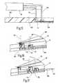
- FIGS. 22 to 24illustrates the controlled guidance of the hook plunger 116 during coupling and decoupling.
- the guide cone 130is offset relative to the central axis of the guide chamber in the circumferential direction of the drum wheel 132, with the hook head 120 projecting laterally toward the test strip 88.
- the spinous process 127forms a lower wall 142 of the guide chamber 12 a guide surface until the elbow 119 against the slope 144 of the guide cone 130 starts.
- the hook head 120is lifted by a pivoting movement of the hook plunger 116, and the pull flank 126 engages behind the edge of the recess 124, while the shear flank 122 abuts against the strip end ( Fig. 23 ).
Landscapes
- Health & Medical Sciences (AREA)
- Life Sciences & Earth Sciences (AREA)
- Physics & Mathematics (AREA)
- Molecular Biology (AREA)
- Animal Behavior & Ethology (AREA)
- Pathology (AREA)
- Engineering & Computer Science (AREA)
- Biomedical Technology (AREA)
- Heart & Thoracic Surgery (AREA)
- Medical Informatics (AREA)
- Hematology (AREA)
- Surgery (AREA)
- Biophysics (AREA)
- General Health & Medical Sciences (AREA)
- Public Health (AREA)
- Veterinary Medicine (AREA)
- Geometry (AREA)
- Dermatology (AREA)
- Investigating Or Analysing Biological Materials (AREA)
- Measurement Of The Respiration, Hearing Ability, Form, And Blood Characteristics Of Living Organisms (AREA)
- Sampling And Sample Adjustment (AREA)
- Automatic Analysis And Handling Materials Therefor (AREA)
Abstract
Description
Translated fromGermanDie Erfindung betrifft eine Vorrichtung zur Aufnahme einer Körperflüssigkeit für Analysezwecke gemäß dem Oberbegriff der unabhängigen Patentansprüche.The invention relates to a device for receiving a body fluid for analysis purposes according to the preamble of the independent claims.
Für die Patienten-Selbstkontrolle insbesondere bei Diabeteserkrankungen sind Einmal- bzw. Schnelltests bekannt, bei denen ein analytisches Testelement mit geringen Mengen einer Körperflüssigkeit beaufschlagt wird, um in einem automatischen Messablauf eine Stoffwechsetgröße zu bestimmen. Speziell für die Blutglucosebestimmung wurden federgetriebene Stechhilfen zur Gewinnung von Kapillarblut entwickelt, welche vom Benutzer beispielsweise an der Fingerbeere angesetzt werden, um durch einen möglichst schmerzarmen Einstich eine ausreichende Blutmenge für die nachfolgende Analyse zu gewinnen. Hierbei wird das ausgetretene Blut mit einem aus einem Messgerät ausgestoßenen Teststreifen als Probenaufnahmeeinheit aufgetupft und dieser nach erfolgter Messung als Verbrauchsmittel verworfen. Neben den immer noch zeitaufwändigen Detailschritten liegt ein besonderes Problem auf diesem Gebiet in der Kontaminations- bzw. Infektionsgefahr durch unkontrolliert in die Umwelt abgegebene Verbrauchsmittel.For patient self-control, especially in diabetes diseases, one-time or rapid tests are known in which an analytical test element is charged with small amounts of body fluid in order to determine a metabolic rate in an automatic measurement procedure. Spring-operated lancing devices for extracting capillary blood have been developed specifically for blood glucose determination, which are set by the user, for example, on the fingertip in order to obtain a sufficient amount of blood for subsequent analysis by a puncture that is as painless as possible. Here, the leaked blood is spotted with a test strip ejected from a meter as a sample receiving unit and this discarded after the measurement as a consumable. In addition to the still time-consuming detail steps is a particular problem in this area in the risk of contamination or infection by uncontrolled released into the environment Consumables.
Eine Vorrichtung gemäß der Präambel von Anspruch 1 ist aus der
Ausgehend hiervon liegt der Erfindung die Aufgabe zugrunde, die im Stand der Technik aufgetretenen Nachteile zu vermeiden und ein System bzw. Verfahren der eingangs angegebenen Art zu optimieren, so dass eine einfache und weitgehend situationsunabhängige Bedienung auch für Laien möglich ist und eine besonders hygienische Handhabung sichergestellt wird.Proceeding from this, the present invention seeks to avoid the disadvantages encountered in the prior art and to optimize a system or method of the type specified, so that a simple and largely situation-independent operation for laymen is possible and ensures a particularly hygienic handling becomes.
Zur Lösung dieser Aufgabe wird die in den unabhängigen Patentansprüchen jeweils angegebene Merkmalskombination vorgeschlagen. Vorteilhafte Ausgestaltungen und Weiterbildungen der Erfindung ergeben sich aus den abhängigen Ansprüchen.To solve this problem, the combination of features specified in the independent claims is proposed. Advantageous embodiments and further developments of the invention will become apparent from the dependent claims.
Die Erfindung basiert auf dem Gedanken, eine Probenaufnahmeeinheit als solche anzutreiben und hierfür mit geeigneten Elementen auszurüsten. Dementsprechend wird erfindungsgemäß eine Kopplungsvorrichtung zum Koppeln der Probenaufnahmeeinheit mit der Antriebseinheit für eine Hin- und Rückbewegung zwischen der Führungskammer und der Aufnahmestelle vorgeschlagen. Der Benutzer muss also die Probenaufnahmeeinheit nicht berühren, sondern kann dies durch das System automatisch ausführen lassen. Dadurch lässt sich die Messung beschleunigt und mit einem hohen Maß an Zuverlässigkeit und Sicherheit durchführen, und es kann durch die Rekassettierung bzw. Rückführung in das Behältnis eine hygienische Handhabung und Entsorgung sichergestellt werden. Für den Patienten bedeutet dies eine erhebliche Erleichterung nicht zuletzt durch die Möglichkeit einer diskreteren Benutzung, ohne sogleich beispielsweise als Diabetiker erkannt zu werden.The invention is based on the idea to drive a sample receiving unit as such and to equip it with suitable elements. Accordingly, a coupling device for coupling the sample receiving unit with the drive unit for a reciprocating movement between the guide chamber and the receiving location is proposed according to the invention. The user therefore does not have to touch the sample receiving unit, but can have it done automatically by the system. As a result, the measurement can be accelerated and performed with a high degree of reliability and safety, and it can be ensured by the Rekassettierung or return to the container hygienic handling and disposal. For the patient, this means a considerable relief, not least because of the possibility of more discrete use, without immediately being recognized as a diabetic, for example.
Eine weitere Verbesserung in dieser Hinsicht wird dadurch erreicht, dass die Kopplungsvorrichtung vorzugsweise selbsttätig arbeitende Verbindungsmittel zum Herstellen und Lösen einer Formschlussverbindung zwischen Antriebseinheit und Probenaufnahmeeinheit aufweist, wobei die Antriebseinheit und die Probenaufnahmeeinheit in einer Ausgangsstellung voneinander getrennt sind. Dies lässt sich vorteilhafterweise dadurch realisieren, dass die Kopplungsvorrichtung mindestens einen bei der Hin- und Rückbewegung wegabhängig zwischen einer Freigabestellung und einer Eingriffstellung bewegbaren Mitnehmer zur Kopplung von Antriebseinheit und Probenaufnahmeeinheit aufweist. Für einen selbstgesteuerten Ablauf ist es von Vorteil, wenn die Kopplungsvorrichtung eine bei der Hin- und Rückbewegung durch den Mitnehmer abtastbare, insbesondere durch eine Anlaufschräge der Führungskammer gebildete Steuerkulisse aufweist.
Eine Vorrichtung gemäss der Erfindung ist in Anspruch 1 definiert.A further improvement in this regard is achieved in that the coupling device preferably comprises automatically operating connection means for establishing and releasing a positive connection between the drive unit and sample receiving unit, wherein the drive unit and the sample receiving unit are separated from each other in a starting position. This can be advantageously realized in that the coupling device has at least one in the outward and return movement path-dependent between a release position and an engagement position movable carrier for coupling drive unit and sample receiving unit. For a self-controlled procedure, it is advantageous if the coupling device has a control link which can be scanned during the forward and backward movement by the driver, in particular formed by a run-on slope of the guide chamber.
A device according to the invention is defined in claim 1.
Vorteilhafterweise ist der Mitnehmer an einem proximalen Ende der Probenaufnahmeeinheit angeordnet und durch mindestens eine vorzugsweise unter Eigenspannung in eine Eingriffstellung einrückbare Halteklaue gebildet. Eine mechanisch besonders einfache Ausführung sieht vor, dass die Antriebseinheit einen Stößel aufweist, und dass der Mitnehmer bei einem Axialvorschub des Stößels selbsttätig mit einer Kopfpartie des Stößels in Eingriff kommt.Advantageously, the driver is arranged at a proximal end of the sample receiving unit and formed by at least one preferably in an inherent tension in an engaged position engageable holding claw. A mechanically particularly simple embodiment provides that the drive unit has a plunger, and that the driver automatically engages with an axial feed of the plunger with a head portion of the plunger.
Eine besonderer Aspekt der Erfindung besteht in einem an der Probenaufnahmeeinheit einhakbaren Hakenstößel als Kopplungsvorrichtung. Für die Hin- bzw. Vorschubbewegung sieht eine vorteilhafte Ausgestaltung vor, dass der Hakenstößel eine gegen die Probenaufnahmeeinheit anschlagende Schubflanke aufweist. Zum Rückholen der Probenaufnahmeeinheit ist es vorteilhaft, wenn der Hakenstößel eine mit der Probenaufnahmeeinheit in Eingriff bringbare Zugflanke aufweist. Um das Ein- und Ausklinken zu erleichtern, ist es günstig, wenn die Zug- und/oder die Schubflanke zu ihrer freien Randkante hin in Richtung der Hinbewegung geneigt sind.A particular aspect of the invention consists in a hook tappet hooked to the sample receiving unit as a coupling device. For the forward or forward movement provides an advantageous embodiment, that the hook plunger has a abutting against the sample receiving unit shear flank. For retrieving the sample receiving unit, it is advantageous if the hook plunger has a pulling flank which can be brought into engagement with the sample receiving unit. In order to facilitate the engagement and disengagement, it is advantageous if the traction and / or the trailing edge are inclined towards their free peripheral edge in the direction of the forward movement.
Um eine zuverlässige Kopplung zu erreichen, ist es von Vorteil, wenn der Hakenstößel einen abgekröpften Hakenkopf aufweist, wobei der Hakenkopf bei der Kopplung zu der Probenaufnahmeeinheit hin seitlich vorspringt. Eine weitere Verbesserung des ergibt sich dadurch, dass der Hakenstößel über ein bei der Hin- und Rückbewegung schräg gegen eine Führungskontur anlaufendes Stößelstück gegenüber der Probenaufnahmeeinheit verschwenkbar ist. Hierbei ist es günstig, wenn der Hakenstößel in einem der Führungskammer vorgelagerten, in Richtung der Hinbewegung sich verjüngenden Führungskonus geführt ist, wobei der Führungskonus gegenüber der Zentralachse der Führungskammer exzentrisch versetzt ist.In order to achieve a reliable coupling, it is advantageous if the hook plunger has a bent hook head, wherein the hook head protrudes laterally in the coupling to the sample receiving unit. A further improvement results from the fact that the hook plunger can be pivoted relative to the sample receiving unit via a plunger piece, which starts obliquely against a guide contour during the forward and backward movement. It is advantageous if the hook plunger in a guide chamber upstream, is guided in the direction of the forward movement tapered guide cone, wherein the guide cone is offset eccentrically relative to the central axis of the guide chamber.
Um das Durchstechen einer Schutzfolie und das Einfahren in die Eingriffstellung zu erleichtern, ist es von Vorteil, wenn der Hakenstößel einen stirnseitig angeformten, gegen die Führungskammer weisenden Dornfortsatz aufweist.In order to facilitate the piercing of a protective film and the retraction into the engagement position, it is advantageous if the hook plunger has a frontally shaped, pointing against the guide chamber spinous process.
Um das Einklinken zu erleichtern und nach der Rückholung eine definierte Sicherung der Probenaufnahmeeinheit zu gewährleisten, ist es vorteilhaft, wenn die robenaufnahmeeinheit durch eine in die Führungskammer vorspringende Klemmstruktur lösbar gehalten ist, wobei die Klemmkraft der Klemmstruktur kleiner als die maximale Antriebskraft der Antriebseinheit sein sollte. Dabei ist es für eine raumsparende Bauform vorteilhaft, wenn die Probenaufnahmeeinheit einen unter Freigabe eines Durchtrittsquerschnitts der Führungskammer zum Ein- und/oder Ausklinken des Hakenstößels in der Klemmstruktur elastisch verformten proximalen Endabschnitt aufweist. Um dies zu erreichen, ist es vorteilhaft, wenn die Klemmstruktur zwei parallel zueinander längs der Führungskammer verlaufende Führungsrippen und zwei in einem der Antriebseinheit zugewandten Klemmbereich der Führungskammer angeordnete, vorzugsweise mit Seitenversatz gegen die Führungsrippen vorspringende Klemmnocken aufweist.In order to facilitate the latching and to ensure a defined backup of the sample receiving unit after retrieval, it is advantageous if the robenaufnahmeeinheit is releasably held by a projecting into the guide chamber clamping structure, wherein the clamping force of the clamping structure should be smaller than the maximum driving force of the drive unit. It is advantageous for a space-saving design, if the sample receiving unit has a releasing a passage cross-section of the guide chamber for engagement and / or notching of the hook plunger in the clamping structure elastically deformed proximal end portion. In order to achieve this, it is advantageous if the clamping structure has two guide ribs extending parallel to one another along the guide chamber and two clamping cams which project in a clamping region of the guide chamber facing the drive unit and preferably project with a lateral offset against the guide ribs.
Vorteilhafterweise besitzt die Probenaufnahmeeinheit eine Ausnehmung als Kopplungselement zum Einhaken des Hakenstößels.Advantageously, the sample receiving unit has a recess as a coupling element for hooking the hook plunger.
Gemäss der Erfindung ist in der Probenaufnahmeeinheit eine Stecheinheit zur Ausführung einer Stechbewegung gegen ein die Körperflüssigkeit enthaltendes Körperteil integriert. Der Einstich und die Probenaufnahme können somit in einem automatischen Bewegungsablauf besonders einfach und hygienisch unter Vermeidung jedweder manueller Eingriffe des Benutzers erfolgen.According to the invention, a lancing unit for performing a lancing movement against a body part containing the body fluid is integrated in the sample receiving unit. The puncture and the sample recording can thus be carried out in an automatic movement particularly simple and hygienic, avoiding any manual intervention by the user.
Für eine besonders günstige teleskopartige Bewegung ist es von Vorteil, wenn die Stecheinheit in einer Führung der Probenaufnahmeeinheit in deren Bewegungsrichtung verschiebbar ist. Dabei kann die Gewinnung der Körperflüssigkeit dadurch optimiert werden, dass die Stecheinheit in einem vorgegebenen Abstand zu einem freien Stirn- bzw. Aufnahmebereich der Probenaufnahmeeinheit in das Körperteil einstechbar ist.For a particularly favorable telescopic movement, it is advantageous if the lancing unit is displaceable in a guide of the sample receiving unit in its direction of movement. In this case, the extraction of the body fluid can be optimized in that the lancing unit can be pierced into the body part at a predetermined distance from a free forehead or receiving area of the sample receiving unit.
Für eine gesonderte Bewegungssteuerung ist es von Vorteil, wenn die Stecheinheit über einen zugeordneten Mitnehmer der Kopplungsvorrichtung für eine hin- und hergehende Stechbewegung formschlüssig mit der Antriebseinheit koppelbar ist. Eine baulich besonders günstige Ausführung sieht vor, dass die Antriebseinheit einen durch einen Außenstößel und einen darin längsverschiebbaren Innenstößel gebildeten Doppelstößel aufweist.For a separate motion control, it is advantageous if the lancing unit can be positively coupled to the drive unit via an associated driver of the coupling device for a reciprocating lancing movement. A structurally particularly favorable embodiment provides that the drive unit has a double plunger formed by an outer tappet and an inner tappet longitudinally displaceable therein.
Zur Ablaufsteuerung der Bewegung von Probenaufnahmeeinheit und Stecheinheit weist die Antriebseinheit eine Steuereinrichtung auf. Zur Steuerung einer Relativbewegung ist es auch möglich, dass die Probenaufnahmeeinheit vorzugsweise durch vorspringende Körperkanten gebildete Anschläge für die Stecheinheit aufweist.For the sequence control of the movement of the sample receiving unit and lancing unit, the drive unit has a control device. In order to control a relative movement, it is also possible that the sample receiving unit preferably has stops for the lancing unit formed by projecting body edges.
Eine weitere vorteilhafte Ausführung sieht vor, dass die Stecheinheit entgegen der Rückstellkraft eines Federglieds gegenüber der Probenaufnahmeeinheit begrenzt verschieblich ist.A further advantageous embodiment provides that the lancing unit is limitedly displaceable against the restoring force of a spring member relative to the sample receiving unit.
Für einen möglichst energiesparenden Bewegungsablauf ist es vorteilhaft, wenn die Probenaufnahmeeinheit in einer Gleitführung der Führungskammer verschiebbar ist.For a most energy-efficient movement, it is advantageous if the sample receiving unit is slidable in a sliding guide of the guide chamber.
Um die Führung und Zentrierung an der vorgesehenen Aufnahmestelle weiter zu verbessern, ist es von Vorteil, wenn die Probenaufnahmeeinheit an einem mittels der Antriebseinheit in der Führungskammer hin und her verschiebbaren Schlitten vorzugsweise über eine Rastverbindung gehalten ist.In order to further improve the guidance and centering at the intended receiving location, it is advantageous if the sample receiving unit is preferably held on a slide which can be moved back and forth in the guide chamber by means of the drive unit via a latching connection.
Vorteilhafterweise besitzt die Probenaufnahmeeinheit einen vorzugsweise kapillaraktiven Transportkanal für eine möglichst selbsttätige Fließverbindung von der Aufnahmestelle zu einer Auswertestelle, welche durch ein spezielles analytisches Testelement zur Untersuchung der Körperflüssigkeit an der Probenaufnahmeeinheit gebildet sein kann.Advantageously, the sample receiving unit has a preferably capillary active transport channel for a possible automatic flow connection from the receiving site to an evaluation point, which may be formed by a special analytical test element for examining the body fluid to the sample receiving unit.
Eine weitere vorteilhafte Ausführung sieht vor, dass der Transportkanal durch einen Ringspalt zwischen einer Lanzette und einem die Lanzette umgebenden Wandbereich der Probenaufnahmeeinheit gebildet ist. Um den Flüssigkeitstransport günstig zu unterstützen, ist es vorteilhaft, wenn der ringförmige Transportkanal in einem von der unter Schwerkraft belasteten Auflageseite der Lanzette abgewandten Transportbereich einen erweiterten Querschnitt besitzt.A further advantageous embodiment provides that the transport channel is formed by an annular gap between a lancet and a wall region of the sample receiving unit surrounding the lancet. In order to support the transport of liquid favorably, it is advantageous if the annular transport channel has an extended cross-section in a transport region facing away from the bearing side of the lancet which is loaded under gravity.
Hierbei ist es günstig, wenn der Transportkanal über eine seitliche Auslassöffnung vorzugsweise in dem Transportbereich auf einem analytischen Testfeld mündet. Möglich ist es auch, dass der Transportkanal über eine in Kanalrichtung weisende axiale Auslassöffnung an einer analytischen Testhülse mündet.In this case, it is expedient if the transport channel preferably opens in the transport region on an analytical test field via a lateral outlet opening. It is also possible that the transport channel opens via an axial outlet opening pointing in the channel direction on an analytical test sleeve.
Zum Schutz vor schädlichen Umwelteinflüssen ist es günstig, wenn die Führungskammer zumindest im Bereich einer Ausschuböffnung durch eine Siegelfolie verschlossen ist. Dabei sollte die Probenaufnahmeeinheit einen in Vorschubrichtung weisenden freien Stirnbereich zum Durchstoßen der Siegelfolie aufweisen, so dass Beschädigungen der Stecheinheit vermieden werden.For protection against harmful environmental influences, it is favorable if the guide chamber is closed by a sealing film at least in the region of an ejection opening. In this case, the sample receiving unit should have a pointing in the feed direction free end region for piercing the sealing film, so that damage to the lancing unit can be avoided.
Vorteilhafterweise ist die Probenaufnahmeeinheit als Teststreifen oder vorzugsweise spritzgegossener Testkörper insbesondere für Blutuntersuchungen ausgebildet. Eine weitere vorteilhafte Variante sieht vor, dass die Probenaufnahmeeinheit durch eine vorzugsweise zugleich als Führung für die Stecheinheit ausgebildete Kanüle zum Ansaugen der Probenflüssigkeit gebildet ist.Advantageously, the sample receiving unit is designed as a test strip or preferably injection-molded test body, in particular for blood tests. A further advantageous variant provides that the sample receiving unit is formed by a cannula, preferably also designed as a guide for the lancing unit, for sucking in the sample liquid.
Um den Bedienungskomfort weiter zu verbessern, ist es vorteilhaft, wenn das Behältnis als Magazin zur Bevorratung einer Mehrzahl von Probenaufnahmeeinheiten ausgebildet ist. In einer für die Bewegungssteuerung günstigen Ausführung kann das Behältnis als Trommelmagazin eine Mehrzahl von in Umfangsrichtung verteilt angeordneten, axial verlaufenden Führungskammern für jeweils eine Probenaufnahmeeinheit aufweist. Alternativ sieht eine besonders kompakte Ausführung vor, dass das Behältnis als Scheibenmagazin eine Mehrzahl von sternförmig angeordneten, radial verlaufenden Führungskammern für jeweils eine Probenaufnahmeeinheit aufweist.To further improve the ease of use, it is advantageous if the container is designed as a magazine for storing a plurality of sample receiving units. In a favorable for the movement control design, the container as a drum magazine a plurality comprising, distributed in the circumferential direction, axially extending guide chambers for each a sample receiving unit. Alternatively, a particularly compact embodiment provides that the container has as disk magazine a plurality of star-shaped, radially extending guide chambers for each one sample receiving unit.
Die Erfindung erstreckt sich auch auf ein Analysegerät, insbesondere ein transportables Handgerät für die medizinische Diagnostik, mit einer erfindungsgemäßen Vorrichtung zur Aufnahme einer Körperflüssigkeit.The invention also extends to an analysis device, in particular a portable handheld device for medical diagnosis, with a device according to the invention for receiving a body fluid.
In verfahrensmäßiger Hinsicht wird die eingangs genannte Aufgabe dadurch gelöst, dass die mit der Antriebseinheit koppelbare Probenaufnahmeeinheit nach der Probenaufnahme in die Führungskammer zurückgezogen wird. Vorteilhafterweise wird die Körperflüssigkeit durch eine Stechbewegung einer in der Probenaufnahmeeinheit verschiebbaren Stecheinheit im Bereich der Aufnahmestelle gewonnen.In terms of the method, the object mentioned in the introduction is achieved in that the sample receiving unit which can be coupled to the drive unit is retracted into the guide chamber after the sample has been picked up. Advantageously, the body fluid is obtained by a puncturing movement of a lancing unit displaceable in the sample receiving unit in the region of the receiving location.
Im Folgenden wird die Erfindung anhand der in der Zeichnung in schematischer Weise dargestellten Ausführungsbeispiele näher erläutert. Es zeigen:
- Fig. 1
- eine Vorrichtung zur Aufnahme und Analyse von Kapillarblut in einer axial aufgebrochenen perspektivischen Ansicht;
- Fig. 2
- eine Probenaufnahmeeinheit der Vorrichtung nach
Fig. 1 in einer Ausgangsstellung gegenüber einer Antriebseinheit in einem ausschnittsweisen Axialschnitt; - Fig. 3 bis 5
- verschiedene Vorschubstellungen der mit der Antriebseinheit gekoppelten Probenaufnahmeeinheit zur Blutentnahme aus der Fingerbeere in einer
Fig. 2 entsprechenden Darstellung; - Fig. 6
- ein weiteres Ausführungsbeispiel mit einer aus Folienteilen gebildeten streifenförmigen Probenaufnahmeeinheit in einer
Fig. 1 entsprechenden Darstellung; - Fig. 7
- die Probenaufnahmeeinheit nach
Fig. 6 in einem senkrecht zu der Streifenebene verlaufenden Längsmittelschnitt; - Fig. 8
bis 10 - verschiedene Vorschubpositionen der Probenaufnahmeeinheit in einer
Fig. 3 bis 5 entsprechenden Darstellung; - Fig. 11
- ein weiteres Ausführungsbeispiel mit einer an einem Schlitten gelagerten streifenförmigen Probenaufnahmeeinheit in einer
Fig. 6 entsprechenden Ansicht; - Fig. 12
- einen ausschnittsweisen Mittelschnitt der Probenaufnahmeeinheit nach
Fig. 11 senkrecht zur Streifenebene; - Fig. 13
- ein weiteres Ausführungsbeispiel mit an einem Federglied gelagerter streifenförmiger Probenaufnahmeeinheit in einer aufgebrochenen perspektivischen Ansicht;
- Fig. 14
- die Probenaufnahmeeinheit nach
Fig. 13 in einerFig. 12 entsprechenden Darstellung; - Fig. 15
- ein Ausführungsbeispiel einer scheibenförmigen Vorrichtung zur Aufnahme und Untersuchung von Blutproben in einem Axialschnitt;
- Fig. 16 und 17
- die Vorrichtung nach
Fig. 15 in einer Ausgangsstellung und einer Entnahmestellung einer radial ausschiebbaren Probenaufnahmeeinheit in einer ausschnittsweisen perspektivischen Ansicht; - Fig. 18
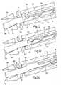
- ein weiteres Ausführungsbeispiel mit einem Hakenstößel für eine Vorschub- und Rückholbewegung eines Teststreifens in einem Längsschnitt;
- Fig. 19
- eine abgebrochene Seitenansicht eines Kopfstücks des abgekröpften Hakenstößels;
- Fig. 20
- einen in einer Führungskammer klemmend gehaltenen Teststreifen in einer Rückseitenansicht;
- Fig. 21
- einen Längsschnitt durch die Führungskammer nach
Fig. 20 ; und - Fig. 22
bis 24 - verschiedene Vorschubstellungen des an dem Teststreifen einhakbaren Hakenstößels in einer perspektivischen Ansicht.
- Fig. 1
- a device for receiving and analyzing capillary blood in an axially broken perspective view;
- Fig. 2
- a sample receiving unit of the device according to
Fig. 1 in a starting position relative to a drive unit in a partial axial section; - Fig. 3 to 5
- different feed positions of the coupled with the drive unit sample receiving unit for blood collection from the fingerberry in one
Fig. 2 corresponding representation; - Fig. 6
- a further embodiment with a strip-shaped sample receiving unit formed from film parts in one
Fig. 1 corresponding representation; - Fig. 7
- the sample receiving unit after
Fig. 6 in a direction perpendicular to the strip plane longitudinal center section; - Fig. 8 to 10
- different feed positions of the sample receiving unit in one
Fig. 3 to 5 corresponding representation; - Fig. 11
- a further embodiment with a mounted on a carriage strip-shaped sample receiving unit in a
Fig. 6 corresponding view; - Fig. 12
- a fragmentary central section of the sample receiving unit after
Fig. 11 perpendicular to the strip plane; - Fig. 13
- a further embodiment with mounted on a spring member strip-shaped sample receiving unit in a broken perspective view;
- Fig. 14
- the sample receiving unit after
Fig. 13 in aFig. 12 corresponding representation; - Fig. 15
- an embodiment of a disc-shaped device for receiving and examining blood samples in an axial section;
- FIGS. 16 and 17
- the device after
Fig. 15 in a starting position and a removal position of a radially ausschiebbaren sample receiving unit in a partial perspective view; - Fig. 18
- a further embodiment with a hook plunger for a feed and return movement of a test strip in a longitudinal section;
- Fig. 19
- a broken side view of a head piece of the bent hook plunger;
- Fig. 20
- a test strip clamped in a guide chamber in a rear view;
- Fig. 21
- a longitudinal section through the guide chamber after
Fig. 20 ; and - FIGS. 22 to 24
- various feed positions of hooked on the test strip hook plunger in a perspective view.
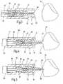
Die in der Zeichnung dargestellte Analysevorrichtung dient zur Blutuntersuchung für die Patienten-Selbstkontrolle speziell für Diabetiker. Das System umfasst ein Vorratsbehältnis 10 mit einer Mehrzahl von Führungskammern 12, in den Führungskammern jeweils einzeln angeordnete Probenaufnahmeeinheiten 14 mit gegebenenfalls integrierter Stecheinheit 16 sowie zugehörige Kopplungsvorrichtungen 18 zum Koppeln der Probenaufnahmeeinheiten bzw. Stecheinheiten mit einer Antriebseinheit 20 für eine Hin- und Rückbewegung zwischen der jeweiligen Führungskammer 12 und einer Aufnahmestelle 22 im Bereich eines Körperteils 24 für die Blutgewinnung.The analysis device shown in the drawing is used for blood testing for patient self-control especially for diabetics. The system comprises a
Wie in
Die Probenaufnahmeeinheiten 14 sind als so genanntes "Disposable" für den Einmalgebrauch bestimmt. Bei der in
Die Lanzettenspitze 58 der Lanzette 52 ist im Ausgangszustand gegenüber dem Stirnrand 60 der Probenaufnahmeeinheit 14 in Vorschubrichtung gesehen zurückversetzt angeordnet. Das proximale Lanzettenende ist mit einem in dem Mitnehmer 42 der Probenaufnahmeeinheit gelagerten zweiten Mitnehmer 62 für eine gesonderte Antriebskopplung versehen.The
Entsprechend besitzt die in
Die Mitnehmer 46, 62 umfassen jeweils zwei Halteklauen 70, 72, welche unter Eigenspannung zangenartig gegeneinander bewegbar sind, um ein zugeordnetes Kopfstück 74, 76 des Außenstößels 66 bzw. Innenstößels 68 formschlüssig zu hintergreifen. Das Einrücken in die Eingriffstellung geschieht beim Stößelvorschub selbsttätig durch Abfahren einer zugeordneten Steuerkulisse 78, 80, wobei die Kulisse 78 für die außen liegenden Halteklauen 70 durch die mit Anlaufschrägen 77 versehenen Schmalseiten der Führungskammern 12 gebildet ist, während der äußere Mitnehmer 46 an seinen Innenflanken eine entsprechende Kulisse 80 für die Halteklauen 72 des inneren Mitnehmers 62 der Stecheinheit 16 bilden.The
In der in
Gemäß
Nach dem Einstich erfolgt die Rückholung der Lanzette 52 und der Probenaufnahmeeinheit 14 in umgekehrter Sequenz entsprechend
Bei den im Folgenden beschriebenen Ausführungsbeispielen sind funktionell gleiche Teile mit gleichen Bezugszeichen wie vorstehend erläutert versehen, so dass insoweit hierauf verwiesen werden kann.In the exemplary embodiments described below, functionally identical parts are provided with the same reference numerals as explained above, so that reference may be made to this extent.
Das in
Der in
Bei der in
Bei dem in
Wie auch bei dem Ausführungsbeispiel gemäß
Die Ausführungsform gemäß
Bei dem in
Der Hakenstößel 116 ist in einer Führungsbuchse 128 gelagert, welche über ein mit konischen Zentrieröffnungen 130 versehenes Trommel- bzw. Indexrad 132 an der Stirnseite des Trommelmagazins 26 auf die gewünschte Führungskammer ausrichtbar ist.The
Wie am besten aus
Bei der Rückwärtsbewegung fährt der Hakenstößel 116 mit der oberen Partie 148 des Kniestücks 119 gegen die obere Konuskante 150 des Führungskonus 130 und wird dadurch bis zum Auskoppeln in der Klemmstellung des Teststreifens 88 nach unten gedrückt. Durch die Neigung der Zugflanke 126 wird sichergestellt, dass die Sperrwirkung geringer ist als die maximale Zugkraft und der Hakenstößel 116 wieder aus der Ausnehmung 124 ausklinkt. Die Führungsbuchse 128 sorgt sowohl beim Vorschub als auch beim Rückholen dafür, dass der Hakenkopf 120 nicht am Trommelrad 132 einhakt. Der verbrauchte Teststreifen 88 wird lagerichtig klemmend zurückgehalten, und es kann auf die nächste Führungskammer in dem Magazin 26 weitergeschaltet werden.During the backward movement of the
Claims (13)
- Device for receiving a body fluid for analytical purposes comprising a container (10) and at least one sample receiving unit (14) preferably for a single-use test that can be pushed out of a guide chamber (12) of the container by means of a drive unit (20) and to which the body fluid can be applied at a receiving site (22) in the area of a body part, and a coupling device (18) to couple the sample receiving unit (14) to the drive unit (20) for a forwards and backwards movement of the sample receiving unit between the guide chamber (12) and the receiving site (22), wherein a lancing unit (16) is integrated in the sample receiving unit (14) to carry out a lancing movement towards the body part (24) containing the body fluid,characterized in that the drive unit (20) has a control device for sequence control of said movement of the sample receiving unit (14) and lancing unit (16).
- Device according to claim 1,characterized in that the lancing unit (16) is slidable in a guide (50) of the sample receiving unit (14) in direction of movement of the sample receiving unit (14).
- Device according to claim 1 or 2,characterized in that the coupling device (18) has preferably automatically operating form-fitting means (46, 74; 62, 76) to make and disengage a form-fitting connection between the drive unit (20) and sample receiving unit (14).
- Device according to one of the claims 1 to 3,characterized in that the drive unit (20) and the sample receiving unit (14) are separated from one another in an initial position.
- Device according to one of the claims 1 to 4,characterized in that the coupling device (18) has at least one engaging means (46, 62) to couple the drive unit (20) and sample receiving unit (14) in a form-fitting manner.
- Device according to claim 5,characterized in that the engaging means (46, 62) can be moved in a distance-dependent manner between a release position and an engaging position during the forwards and backwards movement.
- Device according to claim 5 or 6,characterized in that the coupling device (18) has a sliding guide block (78) and in particular one that is formed by an inclined bevel (77, 80) that can be tracked by the engaging means (46, 62) during the forwards and backwards movement.
- Device according to one of the claims 5 to 7,characterized in that the engaging means (46, 62) is located at a proximal end of the sample receiving unit (14).
- Device according to one of the claims 5 to 8,characterized in that the engaging means (46, 62) is formed by at least one holding claw (70, 72) that can be shifted into an engaging position preferably under its own tension.
- Device according to one of the claims 5 to 9,characterized in that the drive unit (20) has a plunger (64; 66, 68) and that the engaging means (46, 62) automatically engages a head member (74, 76) of the plunger when the plunger (64; 66, 68) is advanced axially.
- Device according to one of the claims 1 to 10,characterized in that the coupling device (18) comprises a hooked plunger (116) that can be hooked onto the sample receiving unit (14).
- Device according to one of the claims 1 to 11,characterized in that the lancing unit (16) can be coupled in a form-fitting manner to the drive unit (20) by means of an associated engaging means (62) of the coupling device (18) for a reciprocating lancing movement.
- Device according to one of the claims 1 to 12,characterized in that the drive unit (20) has a double plunger (64) formed by an outer plunger (66) and an inner plunger (68) that can be longitudinally moved therein to separately drive the sample receiving unit (14) and lancing unit (16).
Applications Claiming Priority (2)
| Application Number | Priority Date | Filing Date | Title |
|---|---|---|---|
| DE10302501ADE10302501A1 (en) | 2003-01-23 | 2003-01-23 | Device and method for absorbing a body fluid for analysis purposes |
| EP04701300AEP1585444B8 (en) | 2003-01-23 | 2004-01-10 | Device for receiving a body fluid for analysis |
Related Parent Applications (1)
| Application Number | Title | Priority Date | Filing Date |
|---|---|---|---|
| EP04701300ADivisionEP1585444B8 (en) | 2003-01-23 | 2004-01-10 | Device for receiving a body fluid for analysis |
Publications (2)
| Publication Number | Publication Date |
|---|---|
| EP2111793A1 EP2111793A1 (en) | 2009-10-28 |
| EP2111793B1true EP2111793B1 (en) | 2015-02-25 |
Family
ID=32667763
Family Applications (2)
| Application Number | Title | Priority Date | Filing Date |
|---|---|---|---|
| EP04701300AExpired - LifetimeEP1585444B8 (en) | 2003-01-23 | 2004-01-10 | Device for receiving a body fluid for analysis |
| EP08169933.2AExpired - LifetimeEP2111793B1 (en) | 2003-01-23 | 2004-01-10 | Device and method for containing a bodily fluid for analysis purposes |
Family Applications Before (1)
| Application Number | Title | Priority Date | Filing Date |
|---|---|---|---|
| EP04701300AExpired - LifetimeEP1585444B8 (en) | 2003-01-23 | 2004-01-10 | Device for receiving a body fluid for analysis |
Country Status (14)
| Country | Link |
|---|---|
| US (2) | US7740599B2 (en) |
| EP (2) | EP1585444B8 (en) |
| JP (1) | JP2006516723A (en) |
| KR (1) | KR100711534B1 (en) |
| CN (1) | CN1741767B (en) |
| AT (1) | ATE415126T1 (en) |
| AU (1) | AU2004206722B2 (en) |
| BR (1) | BRPI0406532B8 (en) |
| CA (1) | CA2513465C (en) |
| DE (2) | DE10302501A1 (en) |
| DK (1) | DK1585444T3 (en) |
| ES (1) | ES2316953T3 (en) |
| MX (1) | MXPA05006651A (en) |
| WO (1) | WO2004064636A1 (en) |
Families Citing this family (128)
| Publication number | Priority date | Publication date | Assignee | Title |
|---|---|---|---|---|
| US6036924A (en)* | 1997-12-04 | 2000-03-14 | Hewlett-Packard Company | Cassette of lancet cartridges for sampling blood |
| US6391005B1 (en) | 1998-03-30 | 2002-05-21 | Agilent Technologies, Inc. | Apparatus and method for penetration with shaft having a sensor for sensing penetration depth |
| DE10057832C1 (en)* | 2000-11-21 | 2002-02-21 | Hartmann Paul Ag | Blood analysis device has syringe mounted in casing, annular mounting carrying needles mounted behind test strip and being swiveled so that needle can be pushed through strip and aperture in casing to take blood sample |
| US8641644B2 (en) | 2000-11-21 | 2014-02-04 | Sanofi-Aventis Deutschland Gmbh | Blood testing apparatus having a rotatable cartridge with multiple lancing elements and testing means |
| US7310543B2 (en) | 2001-03-26 | 2007-12-18 | Kumetrix, Inc. | Silicon microprobe with integrated biosensor |
| US9427532B2 (en) | 2001-06-12 | 2016-08-30 | Sanofi-Aventis Deutschland Gmbh | Tissue penetration device |
| US7981056B2 (en) | 2002-04-19 | 2011-07-19 | Pelikan Technologies, Inc. | Methods and apparatus for lancet actuation |
| WO2002101359A2 (en) | 2001-06-12 | 2002-12-19 | Pelikan Technologies, Inc. | Integrated blood sampling analysis system with multi-use sampling module |
| AU2002344825A1 (en)* | 2001-06-12 | 2002-12-23 | Pelikan Technologies, Inc. | Method and apparatus for improving success rate of blood yield from a fingerstick |
| EP1395185B1 (en) | 2001-06-12 | 2010-10-27 | Pelikan Technologies Inc. | Electric lancet actuator |
| US7041068B2 (en) | 2001-06-12 | 2006-05-09 | Pelikan Technologies, Inc. | Sampling module device and method |
| US7344507B2 (en) | 2002-04-19 | 2008-03-18 | Pelikan Technologies, Inc. | Method and apparatus for lancet actuation |
| US9795747B2 (en) | 2010-06-02 | 2017-10-24 | Sanofi-Aventis Deutschland Gmbh | Methods and apparatus for lancet actuation |
| US8337419B2 (en)* | 2002-04-19 | 2012-12-25 | Sanofi-Aventis Deutschland Gmbh | Tissue penetration device |
| US7749174B2 (en) | 2001-06-12 | 2010-07-06 | Pelikan Technologies, Inc. | Method and apparatus for lancet launching device intergrated onto a blood-sampling cartridge |
| US9226699B2 (en) | 2002-04-19 | 2016-01-05 | Sanofi-Aventis Deutschland Gmbh | Body fluid sampling module with a continuous compression tissue interface surface |
| US20070100255A1 (en)* | 2002-04-19 | 2007-05-03 | Pelikan Technologies, Inc. | Method and apparatus for body fluid sampling and analyte sensing |
| JP4272051B2 (en) | 2001-06-12 | 2009-06-03 | ペリカン テクノロジーズ インコーポレイテッド | Blood sampling apparatus and method |
| JP4209767B2 (en) | 2001-06-12 | 2009-01-14 | ペリカン テクノロジーズ インコーポレイテッド | Self-optimized cutting instrument with adaptive means for temporary changes in skin properties |
| DE10134650B4 (en) | 2001-07-20 | 2009-12-03 | Roche Diagnostics Gmbh | System for taking small amounts of body fluid |
| US7344894B2 (en) | 2001-10-16 | 2008-03-18 | Agilent Technologies, Inc. | Thermal regulation of fluidic samples within a diagnostic cartridge |
| US7004928B2 (en) | 2002-02-08 | 2006-02-28 | Rosedale Medical, Inc. | Autonomous, ambulatory analyte monitor or drug delivery device |
| US7297122B2 (en)* | 2002-04-19 | 2007-11-20 | Pelikan Technologies, Inc. | Method and apparatus for penetrating tissue |
| US7909778B2 (en) | 2002-04-19 | 2011-03-22 | Pelikan Technologies, Inc. | Method and apparatus for penetrating tissue |
| US7491178B2 (en)* | 2002-04-19 | 2009-02-17 | Pelikan Technologies, Inc. | Method and apparatus for penetrating tissue |
| US7648468B2 (en) | 2002-04-19 | 2010-01-19 | Pelikon Technologies, Inc. | Method and apparatus for penetrating tissue |
| US7410468B2 (en)* | 2002-04-19 | 2008-08-12 | Pelikan Technologies, Inc. | Method and apparatus for penetrating tissue |
| US8267870B2 (en) | 2002-04-19 | 2012-09-18 | Sanofi-Aventis Deutschland Gmbh | Method and apparatus for body fluid sampling with hybrid actuation |
| US9248267B2 (en) | 2002-04-19 | 2016-02-02 | Sanofi-Aventis Deustchland Gmbh | Tissue penetration device |
| US7582099B2 (en) | 2002-04-19 | 2009-09-01 | Pelikan Technologies, Inc | Method and apparatus for penetrating tissue |
| US7291117B2 (en) | 2002-04-19 | 2007-11-06 | Pelikan Technologies, Inc. | Method and apparatus for penetrating tissue |
| US8702624B2 (en) | 2006-09-29 | 2014-04-22 | Sanofi-Aventis Deutschland Gmbh | Analyte measurement device with a single shot actuator |
| US7485128B2 (en)* | 2002-04-19 | 2009-02-03 | Pelikan Technologies, Inc. | Method and apparatus for penetrating tissue |
| US7371247B2 (en)* | 2002-04-19 | 2008-05-13 | Pelikan Technologies, Inc | Method and apparatus for penetrating tissue |
| US7674232B2 (en) | 2002-04-19 | 2010-03-09 | Pelikan Technologies, Inc. | Method and apparatus for penetrating tissue |
| US7524293B2 (en)* | 2002-04-19 | 2009-04-28 | Pelikan Technologies, Inc. | Method and apparatus for penetrating tissue |
| US9795334B2 (en) | 2002-04-19 | 2017-10-24 | Sanofi-Aventis Deutschland Gmbh | Method and apparatus for penetrating tissue |
| US7563232B2 (en)* | 2002-04-19 | 2009-07-21 | Pelikan Technologies, Inc. | Method and apparatus for penetrating tissue |
| US7331931B2 (en)* | 2002-04-19 | 2008-02-19 | Pelikan Technologies, Inc. | Method and apparatus for penetrating tissue |
| US7892183B2 (en) | 2002-04-19 | 2011-02-22 | Pelikan Technologies, Inc. | Method and apparatus for body fluid sampling and analyte sensing |
| US7547287B2 (en)* | 2002-04-19 | 2009-06-16 | Pelikan Technologies, Inc. | Method and apparatus for penetrating tissue |
| US7708701B2 (en) | 2002-04-19 | 2010-05-04 | Pelikan Technologies, Inc. | Method and apparatus for a multi-use body fluid sampling device |
| US7717863B2 (en) | 2002-04-19 | 2010-05-18 | Pelikan Technologies, Inc. | Method and apparatus for penetrating tissue |
| US7374544B2 (en) | 2002-04-19 | 2008-05-20 | Pelikan Technologies, Inc. | Method and apparatus for penetrating tissue |
| US7141058B2 (en)* | 2002-04-19 | 2006-11-28 | Pelikan Technologies, Inc. | Method and apparatus for a body fluid sampling device using illumination |
| US7232451B2 (en)* | 2002-04-19 | 2007-06-19 | Pelikan Technologies, Inc. | Method and apparatus for penetrating tissue |
| US8221334B2 (en) | 2002-04-19 | 2012-07-17 | Sanofi-Aventis Deutschland Gmbh | Method and apparatus for penetrating tissue |
| US7901362B2 (en)* | 2002-04-19 | 2011-03-08 | Pelikan Technologies, Inc. | Method and apparatus for penetrating tissue |
| US7229458B2 (en) | 2002-04-19 | 2007-06-12 | Pelikan Technologies, Inc. | Method and apparatus for penetrating tissue |
| US9314194B2 (en)* | 2002-04-19 | 2016-04-19 | Sanofi-Aventis Deutschland Gmbh | Tissue penetration device |
| US8579831B2 (en) | 2002-04-19 | 2013-11-12 | Sanofi-Aventis Deutschland Gmbh | Method and apparatus for penetrating tissue |
| US8784335B2 (en) | 2002-04-19 | 2014-07-22 | Sanofi-Aventis Deutschland Gmbh | Body fluid sampling device with a capacitive sensor |
| US7481776B2 (en)* | 2002-04-19 | 2009-01-27 | Pelikan Technologies, Inc. | Method and apparatus for penetrating tissue |
| US7976476B2 (en)* | 2002-04-19 | 2011-07-12 | Pelikan Technologies, Inc. | Device and method for variable speed lancet |
| EP2286870B1 (en) | 2002-04-26 | 2014-09-03 | EMD Millipore Corporation | Disposable steam sterilisable medical valve |
| US8052926B2 (en)* | 2002-12-27 | 2011-11-08 | Roche Diagnostics Operations, Inc. | Method for manufacturing a sterilized lancet integrated biosensor |
| US7815579B2 (en) | 2005-03-02 | 2010-10-19 | Roche Diagnostics Operations, Inc. | Dynamic integrated lancing test strip with sterility cover |
| US8574895B2 (en) | 2002-12-30 | 2013-11-05 | Sanofi-Aventis Deutschland Gmbh | Method and apparatus using optical techniques to measure analyte levels |
| US7211052B2 (en) | 2002-12-30 | 2007-05-01 | Roche Diagnostics Operations, Inc. | Flexible test strip lancet device |
| US7214200B2 (en) | 2002-12-30 | 2007-05-08 | Roche Diagnostics Operations, Inc. | Integrated analytical test element |
| WO2004060174A2 (en)* | 2002-12-31 | 2004-07-22 | Pelikan Technologies Inc. | Method and apparatus for loading penetrating members |
| US7052652B2 (en) | 2003-03-24 | 2006-05-30 | Rosedale Medical, Inc. | Analyte concentration detection devices and methods |
| DE10325699B3 (en) | 2003-06-06 | 2005-02-10 | Roche Diagnostics Gmbh | System for analyzing a sample to be tested and using such a system |
| US7850621B2 (en) | 2003-06-06 | 2010-12-14 | Pelikan Technologies, Inc. | Method and apparatus for body fluid sampling and analyte sensing |
| WO2005006939A2 (en)* | 2003-06-11 | 2005-01-27 | Pelikan Technologies, Inc. | Method and apparatus for body fluid sampling and analyte sensing |
| WO2006001797A1 (en) | 2004-06-14 | 2006-01-05 | Pelikan Technologies, Inc. | Low pain penetrating |
| EP1635700B1 (en) | 2003-06-13 | 2016-03-09 | Sanofi-Aventis Deutschland GmbH | Apparatus for a point of care device |
| US8282576B2 (en)* | 2003-09-29 | 2012-10-09 | Sanofi-Aventis Deutschland Gmbh | Method and apparatus for an improved sample capture device |
| EP1680014A4 (en)* | 2003-10-14 | 2009-01-21 | Pelikan Technologies Inc | METHOD AND DEVICE FOR A VARIABLE USER INTERFACE |
| US7293477B2 (en) | 2003-12-23 | 2007-11-13 | Millipore Corporation | Disposable, pre-sterilized fluid receptacle sampling device |
| US8668656B2 (en) | 2003-12-31 | 2014-03-11 | Sanofi-Aventis Deutschland Gmbh | Method and apparatus for improving fluidic flow and sample capture |
| US7822454B1 (en) | 2005-01-03 | 2010-10-26 | Pelikan Technologies, Inc. | Fluid sampling device with improved analyte detecting member configuration |
| WO2006011062A2 (en) | 2004-05-20 | 2006-02-02 | Albatros Technologies Gmbh & Co. Kg | Printable hydrogel for biosensors |
| WO2005120365A1 (en) | 2004-06-03 | 2005-12-22 | Pelikan Technologies, Inc. | Method and apparatus for a fluid sampling device |
| US7488298B2 (en) | 2004-10-08 | 2009-02-10 | Roche Diagnostics Operations, Inc. | Integrated lancing test strip with capillary transfer sheet |
| US8652831B2 (en) | 2004-12-30 | 2014-02-18 | Sanofi-Aventis Deutschland Gmbh | Method and apparatus for analyte measurement test time |
| DE102005005017A1 (en) | 2005-02-03 | 2006-08-17 | Roche Diagnostics Gmbh | Electromechanical lancing device for obtaining liquid samples |
| US7935063B2 (en) | 2005-03-02 | 2011-05-03 | Roche Diagnostics Operations, Inc. | System and method for breaking a sterility seal to engage a lancet |
| ATE527536T1 (en) | 2005-03-22 | 2011-10-15 | Hoffmann La Roche | TEST ELEMENT FOR ANALYZING BODY FLUID |
| KR100904106B1 (en) | 2005-04-28 | 2009-06-24 | 파나소닉 주식회사 | Needle insertion instrument and insertion needle cartridge |
| ATE485001T1 (en)* | 2005-05-20 | 2010-11-15 | Hoffmann La Roche | LANCET SYSTEM WITH STERILE PROTECTION |
| US20060281187A1 (en) | 2005-06-13 | 2006-12-14 | Rosedale Medical, Inc. | Analyte detection devices and methods with hematocrit/volume correction and feedback control |
| US20100081968A1 (en)* | 2005-07-15 | 2010-04-01 | Home Diagnostics, Inc. | Test Strip With Integrated Lancet |
| US8636672B2 (en)* | 2007-02-28 | 2014-01-28 | Nipro Diagnostics, Inc. | Test strip with integrated lancet |
| FI121698B (en)* | 2005-07-19 | 2011-03-15 | Ihq Innovation Headquarters Oy | Health monitoring device and sensor cassette for the health monitoring device |
| US8801631B2 (en) | 2005-09-30 | 2014-08-12 | Intuity Medical, Inc. | Devices and methods for facilitating fluid transport |
| EP1928302B1 (en) | 2005-09-30 | 2012-08-01 | Intuity Medical, Inc. | Fully integrated wearable or handheld monitor |
| WO2007044599A2 (en)* | 2005-10-06 | 2007-04-19 | Hamilton Scott E | Pod connected data monitoring system |
| US7641952B2 (en)* | 2006-02-21 | 2010-01-05 | E.I. Du Pont De Nemours And Company | Durable metallized self-adhesive laminates |
| EP1878387B1 (en)* | 2006-07-15 | 2010-11-24 | Roche Diagnostics GmbH | Lancet, lancet feeder belt and pricking device for creating a puncture wound |
| EP1878386A1 (en)* | 2006-07-15 | 2008-01-16 | Roche Diagnostics GmbH | Process to produce lancet; lancet, lancet band and device for pricking the skin |
| GB2440119A (en)* | 2006-07-18 | 2008-01-23 | Owen Mumford Ltd | Skin Pricking Device |
| EP1929937A1 (en)* | 2006-12-07 | 2008-06-11 | F. Hoffmann-Roche AG | Device and method for investigating body fluids |
| EP2152162A1 (en)* | 2007-05-29 | 2010-02-17 | F. Hoffmann-Roche AG | Test element magazine |
| WO2009027950A2 (en)* | 2007-08-29 | 2009-03-05 | Brighter Ab | A portable medical apparatus comprising sampling means, determining means and injecting means |
| EP2030566B1 (en)* | 2007-08-31 | 2016-08-24 | Roche Diabetes Care GmbH | Analysis system for determining an analyte in a body fluid, magazine for an analysis system and analyzing element, and method for analyzing a body fluid |
| WO2009046957A2 (en)* | 2007-10-08 | 2009-04-16 | Roche Diagnostics Gmbh | Analysis system for automatic skin prick analysis |
| SG153002A1 (en) | 2007-11-16 | 2009-06-29 | Millipore Corp | Fluid transfer device |
| EP2265324B1 (en) | 2008-04-11 | 2015-01-28 | Sanofi-Aventis Deutschland GmbH | Integrated analyte measurement system |
| US9833183B2 (en) | 2008-05-30 | 2017-12-05 | Intuity Medical, Inc. | Body fluid sampling device—sampling site interface |
| WO2009148624A1 (en) | 2008-06-06 | 2009-12-10 | Intuity Medical, Inc. | Detection meter and mode of operation |
| EP3984454A1 (en) | 2008-06-06 | 2022-04-20 | Intuity Medical, Inc. | Medical diagnostic devices and methods |
| FR2940440B1 (en) | 2008-12-18 | 2010-12-24 | Millipore Corp | DEVICE FOR TRANSFERRING A MEDIUM |
| FR2940439B1 (en) | 2008-12-18 | 2011-02-11 | Millipore Corp | DEVICE FOR TRANSFERRING A MEDIUM |
| US9375169B2 (en) | 2009-01-30 | 2016-06-28 | Sanofi-Aventis Deutschland Gmbh | Cam drive for managing disposable penetrating member actions with a single motor and motor and control system |
| EP2226007A1 (en) | 2009-02-19 | 2010-09-08 | Roche Diagnostics GmbH | Test element magazine with covered test fields |
| CN102325496B (en)* | 2009-02-19 | 2015-10-07 | 霍夫曼-拉罗奇有限公司 | The joint space-efficient analyzing aid stores |
| EP2226008A1 (en) | 2009-02-19 | 2010-09-08 | Roche Diagnostics GmbH | Method for producing an analytical magazine |
| EP2311374A1 (en)* | 2009-10-13 | 2011-04-20 | Roche Diagnostics GmbH | Apparatus for retrieving and analysing blood; coupling mechanism for lancets |
| US8544497B2 (en) | 2009-10-30 | 2013-10-01 | Emd Millipore Corporation | Fluid transfer device and system |
| EP2506768B1 (en) | 2009-11-30 | 2016-07-06 | Intuity Medical, Inc. | Calibration material delivery devices and methods |
| US8965476B2 (en) | 2010-04-16 | 2015-02-24 | Sanofi-Aventis Deutschland Gmbh | Tissue penetration device |
| CA2803797A1 (en) | 2010-06-25 | 2011-12-29 | Intuity Medical, Inc. | Analyte monitoring methods and systems |
| EP2415395A1 (en)* | 2010-08-04 | 2012-02-08 | Roche Diagnostics GmbH | Medical device with receptacle channel for bodily fluids |
| EP2460471B1 (en)* | 2010-12-04 | 2013-07-03 | Roche Diagnostics GmbH | Lancet device with optionally reusable stored lancets |
| EP2520225B1 (en) | 2011-05-06 | 2014-05-21 | Roche Diagnostics GmbH | Lancet |
| US20130020347A1 (en)* | 2011-06-10 | 2013-01-24 | Union Street Brand Packaging | Strip Dispenser |
| US9782114B2 (en) | 2011-08-03 | 2017-10-10 | Intuity Medical, Inc. | Devices and methods for body fluid sampling and analysis |
| EP3725234A1 (en) | 2012-02-17 | 2020-10-21 | Progenity, Inc. | Ingestible medical device |
| WO2014037011A1 (en)* | 2012-09-05 | 2014-03-13 | Aqm Maxval A/S | Blood sampling needle incorporating measuring capabilities |
| CN102934997B (en)* | 2012-11-09 | 2014-09-24 | 温州市贝普科技有限公司 | Blood sampling pen with multiple needle heads |
| WO2014205412A1 (en) | 2013-06-21 | 2014-12-24 | Intuity Medical, Inc. | Analyte monitoring system with audible feedback |
| KR101529243B1 (en)* | 2013-12-23 | 2015-06-16 | 재단법인 아산사회복지재단 | Interventional procedure robot having needle insertion type |
| US11278225B2 (en)* | 2015-08-12 | 2022-03-22 | University Of Tasmania | Liquid collection device |
| WO2018008672A1 (en)* | 2016-07-06 | 2018-01-11 | ニプロ株式会社 | Specimen sampling tip, specimen preparation container, and specimen preparation kit |
| EP3496614B1 (en)* | 2016-08-12 | 2022-04-06 | Medtrum Technologies Inc. | A one step all in one apparatus for body fluid sampling and sensing |
| US20240252795A1 (en) | 2018-11-19 | 2024-08-01 | Biora Therapeutics, Inc. | Ingestible device for delivery of therapeutic agent to the gastrointestinal tract |
| CN111198269B (en)* | 2018-11-20 | 2023-12-12 | 杭州微策生物技术股份有限公司 | Biological fluid sample detection kit, detection system and application |
Citations (2)
| Publication number | Priority date | Publication date | Assignee | Title |
|---|---|---|---|---|
| GB2335990A (en)* | 1998-03-30 | 1999-10-06 | Hewlett Packard Co | Hypodermic needle having an impedance sensor for sensing penetration depth |
| WO2002100251A2 (en)* | 2001-06-12 | 2002-12-19 | Pelikan Technologies, Inc. | Self optimizing lancing device with adaptation means to temporal variations in cutaneous properties |
Family Cites Families (45)
| Publication number | Priority date | Publication date | Assignee | Title |
|---|---|---|---|---|
| DE2803345C2 (en)* | 1978-01-26 | 1980-02-14 | Emil 7507 Pfinztal Eisinger | Blood sampling device |
| IL80628A0 (en) | 1985-11-18 | 1987-02-27 | Bajada Serge | Apparatus for testing the sensory system in humans or animals |
| US4794926A (en) | 1986-11-24 | 1989-01-03 | Invictus, Inc. | Lancet cartridge |
| EP0301165A3 (en)* | 1987-03-10 | 1991-05-02 | Wagner, Wolfgang, Dr.med. | Metabolism appliance |
| US5250066A (en)* | 1990-03-19 | 1993-10-05 | Becton Dickinson And Company | Plastic pointed articles and method for their preparation |
| US5284156A (en)* | 1991-08-30 | 1994-02-08 | M3 Systems, Inc. | Automatic tissue sampling apparatus |
| US5526822A (en)* | 1994-03-24 | 1996-06-18 | Biopsys Medical, Inc. | Method and apparatus for automated biopsy and collection of soft tissue |
| CA2170560C (en) | 1995-04-17 | 2005-10-25 | Joseph L. Moulton | Means of handling multiple sensors in a glucose monitoring instrument system |
| US5510266A (en) | 1995-05-05 | 1996-04-23 | Bayer Corporation | Method and apparatus of handling multiple sensors in a glucose monitoring instrument system |
| US6332871B1 (en)* | 1996-05-17 | 2001-12-25 | Amira Medical | Blood and interstitial fluid sampling device |
| EP1862116A3 (en)* | 1996-05-17 | 2009-02-25 | Roche Diagnostics Operations, Inc. | Disposable element for use in a body fluid sampling device |
| US7235056B2 (en)* | 1996-05-17 | 2007-06-26 | Amira Medical | Body fluid sampling device and methods of use |
| EP0901634B1 (en) | 1996-05-30 | 2002-03-20 | Radiometer Medical A/S | A system for determining at least one parameter of at least one sample of a physiological liquid and a cassette |
| FI111217B (en) | 1997-06-19 | 2003-06-30 | Nokia Corp | Device for sampling |
| US5829589A (en) | 1997-09-12 | 1998-11-03 | Becton Dickinson And Company | Pen needle magazine dispenser |
| US5971941A (en) | 1997-12-04 | 1999-10-26 | Hewlett-Packard Company | Integrated system and method for sampling blood and analysis |
| US6036924A (en) | 1997-12-04 | 2000-03-14 | Hewlett-Packard Company | Cassette of lancet cartridges for sampling blood |
| JP3139986B2 (en)* | 1997-12-26 | 2001-03-05 | 三鷹光器株式会社 | Biopsy device |
| GB2335004B (en)* | 1998-03-05 | 2002-02-27 | Mbm Technology Ltd | Telescopic piston |
| AU753745B2 (en) | 1998-04-24 | 2002-10-24 | Roche Diagnostics Gmbh | Storage container for analytical devices |
| DE19854316A1 (en) | 1998-04-24 | 1999-10-28 | Roche Diagnostics Gmbh | Container for the aids required for rapid analysis tests outside a laboratory |
| IT1304781B1 (en)* | 1998-12-04 | 2001-03-29 | Gallini S R L | DEVICE FOR THE AUTOMATIC EXECUTION OF BIOPSIES. |
| US6306152B1 (en)* | 1999-03-08 | 2001-10-23 | Agilent Technologies, Inc. | Lancet device with skin movement control and ballistic preload |
| US6706159B2 (en) | 2000-03-02 | 2004-03-16 | Diabetes Diagnostics | Combined lancet and electrochemical analyte-testing apparatus |
| US6375627B1 (en)* | 2000-03-02 | 2002-04-23 | Agilent Technologies, Inc. | Physiological fluid extraction with rapid analysis |
| DE10010694A1 (en) | 2000-03-04 | 2001-09-06 | Roche Diagnostics Gmbh | Lancet including tipped needle with body surrounding tip |
| US6827899B2 (en) | 2000-08-30 | 2004-12-07 | Hypoguard Limited | Test device |
| DE10047419A1 (en) | 2000-09-26 | 2002-04-11 | Roche Diagnostics Gmbh | Lancet system |
| DE10053974A1 (en) | 2000-10-31 | 2002-05-29 | Roche Diagnostics Gmbh | Blood collection system |
| CN101366633B (en) | 2001-01-19 | 2011-03-30 | 松下电器产业株式会社 | Lancet-integrated sensor, measurement device, and biosensor case |
| WO2002056751A2 (en)* | 2001-01-22 | 2002-07-25 | Roche Diagnostics Gmbh | Lancet device having capillary action |
| EP1328192B1 (en)* | 2001-03-29 | 2011-01-05 | Lifescan Scotland Ltd | Integrated sample testing meter |
| ATE343349T1 (en)* | 2001-06-08 | 2006-11-15 | Hoffmann La Roche | DEVICES FOR EXPRESSING BODY FLUID FROM AN INCISION |
| US20020188223A1 (en)* | 2001-06-08 | 2002-12-12 | Edward Perez | Devices and methods for the expression of bodily fluids from an incision |
| CN2479917Y (en)* | 2001-06-18 | 2002-03-06 | 施国平 | Hemostix |
| AU2002320147A1 (en)* | 2001-06-22 | 2003-01-08 | University Of Florida | Microdialysis probes and methods of use |
| DE10142232B4 (en) | 2001-08-29 | 2021-04-29 | Roche Diabetes Care Gmbh | Process for the production of an analytical aid with a lancet and test element |
| CN2516098Y (en)* | 2001-11-12 | 2002-10-16 | 施国平 | Schbier disposable safety automatic blood taking needle |
| EP1450675B1 (en)* | 2001-12-07 | 2012-05-09 | Micronix, Inc. | Consolidated body fluid testing device and method |
| US7892183B2 (en)* | 2002-04-19 | 2011-02-22 | Pelikan Technologies, Inc. | Method and apparatus for body fluid sampling and analyte sensing |
| US7343188B2 (en) | 2002-05-09 | 2008-03-11 | Lifescan, Inc. | Devices and methods for accessing and analyzing physiological fluid |
| US20030223906A1 (en) | 2002-06-03 | 2003-12-04 | Mcallister Devin | Test strip container system |
| US7192405B2 (en)* | 2002-09-30 | 2007-03-20 | Becton, Dickinson And Company | Integrated lancet and bodily fluid sensor |
| DE60332043D1 (en)* | 2002-12-30 | 2010-05-20 | Roche Diagnostics Gmbh | CAPILLARY TUBE TOP DESIGN TO SUPPORT BLOOD FLOW |
| US7604604B2 (en)* | 2004-09-09 | 2009-10-20 | Roche Diagnostics Operations, Inc. | Device for sampling bodily fluids |
- 2003
- 2003-01-23DEDE10302501Apatent/DE10302501A1/ennot_activeWithdrawn
- 2004
- 2004-01-10JPJP2006500540Apatent/JP2006516723A/enactivePending
- 2004-01-10DKDK04701300Tpatent/DK1585444T3/enactive
- 2004-01-10ESES04701300Tpatent/ES2316953T3/ennot_activeExpired - Lifetime
- 2004-01-10DEDE502004008526Tpatent/DE502004008526D1/ennot_activeExpired - Lifetime
- 2004-01-10ATAT04701300Tpatent/ATE415126T1/enactive
- 2004-01-10CNCN2004800027795Apatent/CN1741767B/ennot_activeExpired - Fee Related
- 2004-01-10WOPCT/EP2004/000117patent/WO2004064636A1/enactiveIP Right Grant
- 2004-01-10BRBRPI0406532Apatent/BRPI0406532B8/ennot_activeIP Right Cessation
- 2004-01-10EPEP04701300Apatent/EP1585444B8/ennot_activeExpired - Lifetime
- 2004-01-10AUAU2004206722Apatent/AU2004206722B2/ennot_activeExpired
- 2004-01-10MXMXPA05006651Apatent/MXPA05006651A/enactiveIP Right Grant
- 2004-01-10EPEP08169933.2Apatent/EP2111793B1/ennot_activeExpired - Lifetime
- 2004-01-10CACA2513465Apatent/CA2513465C/ennot_activeExpired - Fee Related
- 2004-01-10KRKR1020057012556Apatent/KR100711534B1/ennot_activeExpired - Fee Related
- 2005
- 2005-07-11USUS11/178,810patent/US7740599B2/ennot_activeExpired - Fee Related
- 2010
- 2010-03-31USUS12/751,178patent/US9757063B2/enactiveActive
Patent Citations (2)
| Publication number | Priority date | Publication date | Assignee | Title |
|---|---|---|---|---|
| GB2335990A (en)* | 1998-03-30 | 1999-10-06 | Hewlett Packard Co | Hypodermic needle having an impedance sensor for sensing penetration depth |
| WO2002100251A2 (en)* | 2001-06-12 | 2002-12-19 | Pelikan Technologies, Inc. | Self optimizing lancing device with adaptation means to temporal variations in cutaneous properties |
Also Published As
| Publication number | Publication date |
|---|---|
| JP2006516723A (en) | 2006-07-06 |
| US7740599B2 (en) | 2010-06-22 |
| BRPI0406532B1 (en) | 2021-02-23 |
| HK1087604A1 (en) | 2006-10-20 |
| EP1585444B1 (en) | 2008-11-26 |
| KR20050093817A (en) | 2005-09-23 |
| AU2004206722B2 (en) | 2009-03-19 |
| US9757063B2 (en) | 2017-09-12 |
| BRPI0406532B8 (en) | 2021-06-22 |
| ES2316953T3 (en) | 2009-04-16 |
| AU2004206722A1 (en) | 2004-08-05 |
| BRPI0406532A (en) | 2005-12-13 |
| DK1585444T3 (en) | 2009-04-06 |
| KR100711534B1 (en) | 2007-04-27 |
| MXPA05006651A (en) | 2005-08-16 |
| EP2111793A1 (en) | 2009-10-28 |
| DE502004008526D1 (en) | 2009-01-08 |
| CA2513465C (en) | 2012-09-11 |
| US20060008389A1 (en) | 2006-01-12 |
| EP1585444A1 (en) | 2005-10-19 |
| DE10302501A1 (en) | 2004-08-05 |
| EP1585444B8 (en) | 2009-04-08 |
| CN1741767B (en) | 2010-05-26 |
| CN1741767A (en) | 2006-03-01 |
| CA2513465A1 (en) | 2004-08-05 |
| ATE415126T1 (en) | 2008-12-15 |
| WO2004064636A1 (en) | 2004-08-05 |
| US20100185120A1 (en) | 2010-07-22 |
Similar Documents
| Publication | Publication Date | Title |
|---|---|---|
| EP2111793B1 (en) | Device and method for containing a bodily fluid for analysis purposes | |
| EP1838239B1 (en) | Testing unit for carrying out a one-time testing of a body fluid | |
| EP1190674B1 (en) | Lancet devices | |
| DE19758805B4 (en) | Device for taking body fluid samples and method for their use | |
| EP2691023B2 (en) | Lancet magazine for puncturing aids | |
| EP2263535B1 (en) | System for withdrawing blood | |
| EP2229887B1 (en) | Lancet device with sterile protection | |
| DE10245721A1 (en) | Blood analyzer device comprises needles, test media, analyzer and display, and has carrier turned with respect to main body, to position needle and test media | |
| EP0630609A2 (en) | Blood lancet device for obtaining blood samples for diagnosis purposes | |
| EP1929937A1 (en) | Device and method for investigating body fluids | |
| EP2311373B1 (en) | Piercing system for removal of a body fluid | |
| WO2014029521A1 (en) | Lancing device for obtaining samples of body fluid | |
| DE102011015590B4 (en) | Lancing device with at least one lancet for the recovery of body fluids |
Legal Events
| Date | Code | Title | Description |
|---|---|---|---|
| PUAI | Public reference made under article 153(3) epc to a published international application that has entered the european phase | Free format text:ORIGINAL CODE: 0009012 | |
| AC | Divisional application: reference to earlier application | Ref document number:1585444 Country of ref document:EP Kind code of ref document:P | |
| AK | Designated contracting states | Kind code of ref document:A1 Designated state(s):AT BE BG CH CY CZ DE DK EE ES FI FR GB GR HU IE IT LI LU MC NL PT RO SE SI SK TR | |
| 17P | Request for examination filed | Effective date:20100427 | |
| AKX | Designation fees paid | Designated state(s):AT BE BG CH CY CZ DE DK EE ES FI FR GB GR HU IE IT LI LU MC NL PT RO SE SI SK TR | |
| 17Q | First examination report despatched | Effective date:20100629 | |
| GRAP | Despatch of communication of intention to grant a patent | Free format text:ORIGINAL CODE: EPIDOSNIGR1 | |
| INTG | Intention to grant announced | Effective date:20140612 | |
| GRAP | Despatch of communication of intention to grant a patent | Free format text:ORIGINAL CODE: EPIDOSNIGR1 | |
| INTG | Intention to grant announced | Effective date:20140904 | |
| GRAS | Grant fee paid | Free format text:ORIGINAL CODE: EPIDOSNIGR3 | |
| GRAA | (expected) grant | Free format text:ORIGINAL CODE: 0009210 | |
| AC | Divisional application: reference to earlier application | Ref document number:1585444 Country of ref document:EP Kind code of ref document:P | |
| AK | Designated contracting states | Kind code of ref document:B1 Designated state(s):AT BE BG CH CY CZ DE DK EE ES FI FR GB GR HU IE IT LI LU MC NL PT RO SE SI SK TR | |
| REG | Reference to a national code | Ref country code:GB Ref legal event code:FG4D Free format text:NOT ENGLISH | |
| REG | Reference to a national code | Ref country code:CH Ref legal event code:EP | |
| REG | Reference to a national code | Ref country code:IE Ref legal event code:FG4D Free format text:LANGUAGE OF EP DOCUMENT: GERMAN | |
| REG | Reference to a national code | Ref country code:DE Ref legal event code:R096 Ref document number:502004014839 Country of ref document:DE Effective date:20150409 | |
| REG | Reference to a national code | Ref country code:AT Ref legal event code:REF Ref document number:711214 Country of ref document:AT Kind code of ref document:T Effective date:20150415 | |
| REG | Reference to a national code | Ref country code:NL Ref legal event code:VDEP Effective date:20150225 | |
| PG25 | Lapsed in a contracting state [announced via postgrant information from national office to epo] | Ref country code:SE Free format text:LAPSE BECAUSE OF FAILURE TO SUBMIT A TRANSLATION OF THE DESCRIPTION OR TO PAY THE FEE WITHIN THE PRESCRIBED TIME-LIMIT Effective date:20150225 Ref country code:ES Free format text:LAPSE BECAUSE OF FAILURE TO SUBMIT A TRANSLATION OF THE DESCRIPTION OR TO PAY THE FEE WITHIN THE PRESCRIBED TIME-LIMIT Effective date:20150225 Ref country code:FI Free format text:LAPSE BECAUSE OF FAILURE TO SUBMIT A TRANSLATION OF THE DESCRIPTION OR TO PAY THE FEE WITHIN THE PRESCRIBED TIME-LIMIT Effective date:20150225 | |
| PG25 | Lapsed in a contracting state [announced via postgrant information from national office to epo] | Ref country code:GR Free format text:LAPSE BECAUSE OF FAILURE TO SUBMIT A TRANSLATION OF THE DESCRIPTION OR TO PAY THE FEE WITHIN THE PRESCRIBED TIME-LIMIT Effective date:20150526 | |
| PG25 | Lapsed in a contracting state [announced via postgrant information from national office to epo] | Ref country code:NL Free format text:LAPSE BECAUSE OF FAILURE TO SUBMIT A TRANSLATION OF THE DESCRIPTION OR TO PAY THE FEE WITHIN THE PRESCRIBED TIME-LIMIT Effective date:20150225 | |
| PG25 | Lapsed in a contracting state [announced via postgrant information from national office to epo] | Ref country code:DK Free format text:LAPSE BECAUSE OF FAILURE TO SUBMIT A TRANSLATION OF THE DESCRIPTION OR TO PAY THE FEE WITHIN THE PRESCRIBED TIME-LIMIT Effective date:20150225 Ref country code:CZ Free format text:LAPSE BECAUSE OF FAILURE TO SUBMIT A TRANSLATION OF THE DESCRIPTION OR TO PAY THE FEE WITHIN THE PRESCRIBED TIME-LIMIT Effective date:20150225 Ref country code:RO Free format text:LAPSE BECAUSE OF FAILURE TO SUBMIT A TRANSLATION OF THE DESCRIPTION OR TO PAY THE FEE WITHIN THE PRESCRIBED TIME-LIMIT Effective date:20150225 Ref country code:SK Free format text:LAPSE BECAUSE OF FAILURE TO SUBMIT A TRANSLATION OF THE DESCRIPTION OR TO PAY THE FEE WITHIN THE PRESCRIBED TIME-LIMIT Effective date:20150225 Ref country code:EE Free format text:LAPSE BECAUSE OF FAILURE TO SUBMIT A TRANSLATION OF THE DESCRIPTION OR TO PAY THE FEE WITHIN THE PRESCRIBED TIME-LIMIT Effective date:20150225 | |
| REG | Reference to a national code | Ref country code:DE Ref legal event code:R097 Ref document number:502004014839 Country of ref document:DE | |
| REG | Reference to a national code | Ref country code:FR Ref legal event code:PLFP Year of fee payment:13 | |
| PLBE | No opposition filed within time limit | Free format text:ORIGINAL CODE: 0009261 | |
| STAA | Information on the status of an ep patent application or granted ep patent | Free format text:STATUS: NO OPPOSITION FILED WITHIN TIME LIMIT | |
| 26N | No opposition filed | Effective date:20151126 | |
| PG25 | Lapsed in a contracting state [announced via postgrant information from national office to epo] | Ref country code:SI Free format text:LAPSE BECAUSE OF FAILURE TO SUBMIT A TRANSLATION OF THE DESCRIPTION OR TO PAY THE FEE WITHIN THE PRESCRIBED TIME-LIMIT Effective date:20150225 | |
| REG | Reference to a national code | Ref country code:DE Ref legal event code:R082 Ref document number:502004014839 Country of ref document:DE Representative=s name:WOLF, PFIZ & GAUSS PATENTANWAELTE PARTNERSCHAF, DE Ref country code:DE Ref legal event code:R081 Ref document number:502004014839 Country of ref document:DE Owner name:ROCHE DIABETES CARE GMBH, DE Free format text:FORMER OWNER: ROCHE DIAGNOSTICS GMBH, 68305 MANNHEIM, DE Ref country code:DE Ref legal event code:R082 Ref document number:502004014839 Country of ref document:DE Representative=s name:PFIZ/GAUSS PATENTANWAELTE PARTMBB, DE | |
| PG25 | Lapsed in a contracting state [announced via postgrant information from national office to epo] | Ref country code:BE Free format text:LAPSE BECAUSE OF NON-PAYMENT OF DUE FEES Effective date:20160131 | |
| PG25 | Lapsed in a contracting state [announced via postgrant information from national office to epo] | Ref country code:LU Free format text:LAPSE BECAUSE OF FAILURE TO SUBMIT A TRANSLATION OF THE DESCRIPTION OR TO PAY THE FEE WITHIN THE PRESCRIBED TIME-LIMIT Effective date:20160110 | |
| REG | Reference to a national code | Ref country code:CH Ref legal event code:PL | |
| PG25 | Lapsed in a contracting state [announced via postgrant information from national office to epo] | Ref country code:MC Free format text:LAPSE BECAUSE OF FAILURE TO SUBMIT A TRANSLATION OF THE DESCRIPTION OR TO PAY THE FEE WITHIN THE PRESCRIBED TIME-LIMIT Effective date:20150225 | |
| PG25 | Lapsed in a contracting state [announced via postgrant information from national office to epo] | Ref country code:LI Free format text:LAPSE BECAUSE OF NON-PAYMENT OF DUE FEES Effective date:20160131 Ref country code:CH Free format text:LAPSE BECAUSE OF NON-PAYMENT OF DUE FEES Effective date:20160131 | |
| REG | Reference to a national code | Ref country code:IE Ref legal event code:MM4A | |
| REG | Reference to a national code | Ref country code:FR Ref legal event code:PLFP Year of fee payment:14 | |
| PG25 | Lapsed in a contracting state [announced via postgrant information from national office to epo] | Ref country code:IE Free format text:LAPSE BECAUSE OF NON-PAYMENT OF DUE FEES Effective date:20160110 | |
| REG | Reference to a national code | Ref country code:AT Ref legal event code:MM01 Ref document number:711214 Country of ref document:AT Kind code of ref document:T Effective date:20160110 | |
| PG25 | Lapsed in a contracting state [announced via postgrant information from national office to epo] | Ref country code:AT Free format text:LAPSE BECAUSE OF NON-PAYMENT OF DUE FEES Effective date:20160110 | |
| REG | Reference to a national code | Ref country code:FR Ref legal event code:PLFP Year of fee payment:15 | |
| PG25 | Lapsed in a contracting state [announced via postgrant information from national office to epo] | Ref country code:CY Free format text:LAPSE BECAUSE OF FAILURE TO SUBMIT A TRANSLATION OF THE DESCRIPTION OR TO PAY THE FEE WITHIN THE PRESCRIBED TIME-LIMIT Effective date:20150225 Ref country code:HU Free format text:LAPSE BECAUSE OF FAILURE TO SUBMIT A TRANSLATION OF THE DESCRIPTION OR TO PAY THE FEE WITHIN THE PRESCRIBED TIME-LIMIT; INVALID AB INITIO Effective date:20040110 | |
| PG25 | Lapsed in a contracting state [announced via postgrant information from national office to epo] | Ref country code:PT Free format text:LAPSE BECAUSE OF FAILURE TO SUBMIT A TRANSLATION OF THE DESCRIPTION OR TO PAY THE FEE WITHIN THE PRESCRIBED TIME-LIMIT Effective date:20150225 Ref country code:TR Free format text:LAPSE BECAUSE OF FAILURE TO SUBMIT A TRANSLATION OF THE DESCRIPTION OR TO PAY THE FEE WITHIN THE PRESCRIBED TIME-LIMIT Effective date:20150225 | |
| PG25 | Lapsed in a contracting state [announced via postgrant information from national office to epo] | Ref country code:BG Free format text:LAPSE BECAUSE OF FAILURE TO SUBMIT A TRANSLATION OF THE DESCRIPTION OR TO PAY THE FEE WITHIN THE PRESCRIBED TIME-LIMIT Effective date:20150225 | |
| PGFP | Annual fee paid to national office [announced via postgrant information from national office to epo] | Ref country code:FR Payment date:20201223 Year of fee payment:18 Ref country code:GB Payment date:20201231 Year of fee payment:18 | |
| PGFP | Annual fee paid to national office [announced via postgrant information from national office to epo] | Ref country code:IT Payment date:20210121 Year of fee payment:18 | |
| PGFP | Annual fee paid to national office [announced via postgrant information from national office to epo] | Ref country code:DE Payment date:20201218 Year of fee payment:18 | |
| REG | Reference to a national code | Ref country code:DE Ref legal event code:R119 Ref document number:502004014839 Country of ref document:DE | |
| GBPC | Gb: european patent ceased through non-payment of renewal fee | Effective date:20220110 | |
| PG25 | Lapsed in a contracting state [announced via postgrant information from national office to epo] | Ref country code:GB Free format text:LAPSE BECAUSE OF NON-PAYMENT OF DUE FEES Effective date:20220110 Ref country code:DE Free format text:LAPSE BECAUSE OF NON-PAYMENT OF DUE FEES Effective date:20220802 | |
| PG25 | Lapsed in a contracting state [announced via postgrant information from national office to epo] | Ref country code:FR Free format text:LAPSE BECAUSE OF NON-PAYMENT OF DUE FEES Effective date:20220131 | |
| PG25 | Lapsed in a contracting state [announced via postgrant information from national office to epo] | Ref country code:IT Free format text:LAPSE BECAUSE OF NON-PAYMENT OF DUE FEES Effective date:20220110 |