EP2110302A1 - Bicycle component - Google Patents
Bicycle componentDownload PDFInfo
- Publication number
- EP2110302A1 EP2110302A1EP20090009916EP09009916AEP2110302A1EP 2110302 A1EP2110302 A1EP 2110302A1EP 20090009916EP20090009916EP 20090009916EP 09009916 AEP09009916 AEP 09009916AEP 2110302 A1EP2110302 A1EP 2110302A1
- Authority
- EP
- European Patent Office
- Prior art keywords
- component
- seat
- structural fibres
- fibres
- continuous layer
- Prior art date
- Legal status (The legal status is an assumption and is not a legal conclusion. Google has not performed a legal analysis and makes no representation as to the accuracy of the status listed.)
- Ceased
Links
Images


Classifications
- B—PERFORMING OPERATIONS; TRANSPORTING
- B29—WORKING OF PLASTICS; WORKING OF SUBSTANCES IN A PLASTIC STATE IN GENERAL
- B29C—SHAPING OR JOINING OF PLASTICS; SHAPING OF MATERIAL IN A PLASTIC STATE, NOT OTHERWISE PROVIDED FOR; AFTER-TREATMENT OF THE SHAPED PRODUCTS, e.g. REPAIRING
- B29C70/00—Shaping composites, i.e. plastics material comprising reinforcements, fillers or preformed parts, e.g. inserts
- B29C70/68—Shaping composites, i.e. plastics material comprising reinforcements, fillers or preformed parts, e.g. inserts by incorporating or moulding on preformed parts, e.g. inserts or layers, e.g. foam blocks
- B29C70/86—Incorporated in coherent impregnated reinforcing layers, e.g. by winding
- B—PERFORMING OPERATIONS; TRANSPORTING
- B29—WORKING OF PLASTICS; WORKING OF SUBSTANCES IN A PLASTIC STATE IN GENERAL
- B29C—SHAPING OR JOINING OF PLASTICS; SHAPING OF MATERIAL IN A PLASTIC STATE, NOT OTHERWISE PROVIDED FOR; AFTER-TREATMENT OF THE SHAPED PRODUCTS, e.g. REPAIRING
- B29C70/00—Shaping composites, i.e. plastics material comprising reinforcements, fillers or preformed parts, e.g. inserts
- B29C70/04—Shaping composites, i.e. plastics material comprising reinforcements, fillers or preformed parts, e.g. inserts comprising reinforcements only, e.g. self-reinforcing plastics
- B29C70/06—Fibrous reinforcements only
- B29C70/08—Fibrous reinforcements only comprising combinations of different forms of fibrous reinforcements incorporated in matrix material, forming one or more layers, and with or without non-reinforced layers
- B29C70/081—Combinations of fibres of continuous or substantial length and short fibres
- B—PERFORMING OPERATIONS; TRANSPORTING
- B29—WORKING OF PLASTICS; WORKING OF SUBSTANCES IN A PLASTIC STATE IN GENERAL
- B29C—SHAPING OR JOINING OF PLASTICS; SHAPING OF MATERIAL IN A PLASTIC STATE, NOT OTHERWISE PROVIDED FOR; AFTER-TREATMENT OF THE SHAPED PRODUCTS, e.g. REPAIRING
- B29C70/00—Shaping composites, i.e. plastics material comprising reinforcements, fillers or preformed parts, e.g. inserts
- B29C70/04—Shaping composites, i.e. plastics material comprising reinforcements, fillers or preformed parts, e.g. inserts comprising reinforcements only, e.g. self-reinforcing plastics
- B29C70/06—Fibrous reinforcements only
- B29C70/10—Fibrous reinforcements only characterised by the structure of fibrous reinforcements, e.g. hollow fibres
- B29C70/16—Fibrous reinforcements only characterised by the structure of fibrous reinforcements, e.g. hollow fibres using fibres of substantial or continuous length
- B29C70/20—Fibrous reinforcements only characterised by the structure of fibrous reinforcements, e.g. hollow fibres using fibres of substantial or continuous length oriented in a single direction, e.g. roofing or other parallel fibres
- B29C70/202—Fibrous reinforcements only characterised by the structure of fibrous reinforcements, e.g. hollow fibres using fibres of substantial or continuous length oriented in a single direction, e.g. roofing or other parallel fibres arranged in parallel planes or structures of fibres crossing at substantial angles, e.g. cross-moulding compound [XMC]
- B—PERFORMING OPERATIONS; TRANSPORTING
- B29—WORKING OF PLASTICS; WORKING OF SUBSTANCES IN A PLASTIC STATE IN GENERAL
- B29C—SHAPING OR JOINING OF PLASTICS; SHAPING OF MATERIAL IN A PLASTIC STATE, NOT OTHERWISE PROVIDED FOR; AFTER-TREATMENT OF THE SHAPED PRODUCTS, e.g. REPAIRING
- B29C70/00—Shaping composites, i.e. plastics material comprising reinforcements, fillers or preformed parts, e.g. inserts
- B29C70/04—Shaping composites, i.e. plastics material comprising reinforcements, fillers or preformed parts, e.g. inserts comprising reinforcements only, e.g. self-reinforcing plastics
- B29C70/06—Fibrous reinforcements only
- B29C70/10—Fibrous reinforcements only characterised by the structure of fibrous reinforcements, e.g. hollow fibres
- B29C70/16—Fibrous reinforcements only characterised by the structure of fibrous reinforcements, e.g. hollow fibres using fibres of substantial or continuous length
- B29C70/22—Fibrous reinforcements only characterised by the structure of fibrous reinforcements, e.g. hollow fibres using fibres of substantial or continuous length oriented in at least two directions forming a two dimensional structure
- B—PERFORMING OPERATIONS; TRANSPORTING
- B29—WORKING OF PLASTICS; WORKING OF SUBSTANCES IN A PLASTIC STATE IN GENERAL
- B29C—SHAPING OR JOINING OF PLASTICS; SHAPING OF MATERIAL IN A PLASTIC STATE, NOT OTHERWISE PROVIDED FOR; AFTER-TREATMENT OF THE SHAPED PRODUCTS, e.g. REPAIRING
- B29C70/00—Shaping composites, i.e. plastics material comprising reinforcements, fillers or preformed parts, e.g. inserts
- B29C70/04—Shaping composites, i.e. plastics material comprising reinforcements, fillers or preformed parts, e.g. inserts comprising reinforcements only, e.g. self-reinforcing plastics
- B29C70/28—Shaping operations therefor
- B29C70/40—Shaping or impregnating by compression not applied
- B29C70/42—Shaping or impregnating by compression not applied for producing articles of definite length, i.e. discrete articles
- B29C70/46—Shaping or impregnating by compression not applied for producing articles of definite length, i.e. discrete articles using matched moulds, e.g. for deforming sheet moulding compounds [SMC] or prepregs
- B—PERFORMING OPERATIONS; TRANSPORTING
- B62—LAND VEHICLES FOR TRAVELLING OTHERWISE THAN ON RAILS
- B62K—CYCLES; CYCLE FRAMES; CYCLE STEERING DEVICES; RIDER-OPERATED TERMINAL CONTROLS SPECIALLY ADAPTED FOR CYCLES; CYCLE AXLE SUSPENSIONS; CYCLE SIDE-CARS, FORECARS, OR THE LIKE
- B62K19/00—Cycle frames
- B62K19/02—Cycle frames characterised by material or cross-section of frame members
- B62K19/16—Cycle frames characterised by material or cross-section of frame members the material being wholly or mainly of plastics
- B—PERFORMING OPERATIONS; TRANSPORTING
- B62—LAND VEHICLES FOR TRAVELLING OTHERWISE THAN ON RAILS
- B62M—RIDER PROPULSION OF WHEELED VEHICLES OR SLEDGES; POWERED PROPULSION OF SLEDGES OR SINGLE-TRACK CYCLES; TRANSMISSIONS SPECIALLY ADAPTED FOR SUCH VEHICLES
- B62M3/00—Construction of cranks operated by hand or foot
- B—PERFORMING OPERATIONS; TRANSPORTING
- B29—WORKING OF PLASTICS; WORKING OF SUBSTANCES IN A PLASTIC STATE IN GENERAL
- B29L—INDEXING SCHEME ASSOCIATED WITH SUBCLASS B29C, RELATING TO PARTICULAR ARTICLES
- B29L2031/00—Other particular articles
- B29L2031/06—Rods, e.g. connecting rods, rails, stakes
- B—PERFORMING OPERATIONS; TRANSPORTING
- B29—WORKING OF PLASTICS; WORKING OF SUBSTANCES IN A PLASTIC STATE IN GENERAL
- B29L—INDEXING SCHEME ASSOCIATED WITH SUBCLASS B29C, RELATING TO PARTICULAR ARTICLES
- B29L2031/00—Other particular articles
- B29L2031/30—Vehicles, e.g. ships or aircraft, or body parts thereof
- B29L2031/3091—Bicycles
- Y—GENERAL TAGGING OF NEW TECHNOLOGICAL DEVELOPMENTS; GENERAL TAGGING OF CROSS-SECTIONAL TECHNOLOGIES SPANNING OVER SEVERAL SECTIONS OF THE IPC; TECHNICAL SUBJECTS COVERED BY FORMER USPC CROSS-REFERENCE ART COLLECTIONS [XRACs] AND DIGESTS
- Y10—TECHNICAL SUBJECTS COVERED BY FORMER USPC
- Y10T—TECHNICAL SUBJECTS COVERED BY FORMER US CLASSIFICATION
- Y10T428/00—Stock material or miscellaneous articles
- Y10T428/24—Structurally defined web or sheet [e.g., overall dimension, etc.]
- Y10T428/24132—Structurally defined web or sheet [e.g., overall dimension, etc.] including grain, strips, or filamentary elements in different layers or components parallel
- Y—GENERAL TAGGING OF NEW TECHNOLOGICAL DEVELOPMENTS; GENERAL TAGGING OF CROSS-SECTIONAL TECHNOLOGIES SPANNING OVER SEVERAL SECTIONS OF THE IPC; TECHNICAL SUBJECTS COVERED BY FORMER USPC CROSS-REFERENCE ART COLLECTIONS [XRACs] AND DIGESTS
- Y10—TECHNICAL SUBJECTS COVERED BY FORMER USPC
- Y10T—TECHNICAL SUBJECTS COVERED BY FORMER US CLASSIFICATION
- Y10T428/00—Stock material or miscellaneous articles
- Y10T428/249921—Web or sheet containing structurally defined element or component
- Y10T428/249924—Noninterengaged fiber-containing paper-free web or sheet which is not of specified porosity
- Y10T428/249933—Fiber embedded in or on the surface of a natural or synthetic rubber matrix
- Y10T428/249939—Two or more layers
- Y—GENERAL TAGGING OF NEW TECHNOLOGICAL DEVELOPMENTS; GENERAL TAGGING OF CROSS-SECTIONAL TECHNOLOGIES SPANNING OVER SEVERAL SECTIONS OF THE IPC; TECHNICAL SUBJECTS COVERED BY FORMER USPC CROSS-REFERENCE ART COLLECTIONS [XRACs] AND DIGESTS
- Y10—TECHNICAL SUBJECTS COVERED BY FORMER USPC
- Y10T—TECHNICAL SUBJECTS COVERED BY FORMER US CLASSIFICATION
- Y10T442/00—Fabric [woven, knitted, or nonwoven textile or cloth, etc.]
- Y10T442/60—Nonwoven fabric [i.e., nonwoven strand or fiber material]
- Y—GENERAL TAGGING OF NEW TECHNOLOGICAL DEVELOPMENTS; GENERAL TAGGING OF CROSS-SECTIONAL TECHNOLOGIES SPANNING OVER SEVERAL SECTIONS OF THE IPC; TECHNICAL SUBJECTS COVERED BY FORMER USPC CROSS-REFERENCE ART COLLECTIONS [XRACs] AND DIGESTS
- Y10—TECHNICAL SUBJECTS COVERED BY FORMER USPC
- Y10T—TECHNICAL SUBJECTS COVERED BY FORMER US CLASSIFICATION
- Y10T74/00—Machine element or mechanism
- Y10T74/21—Elements
- Y10T74/2164—Cranks and pedals
Definitions
- the present inventionrelates to a bicycle component particularly suitable for being used in the assemblage of bicycle parts where high specific pressures are to be dealt with.
- the component being referred tois a pedal crank, but what said can be extended to bicycle components which are different but which have characteristics similar to those of a pedal crank, like, for example, the seat tube.
- the composite material used in such a caseis preferably of the type described in US 4 339 490 and consists of sheets formed of a resin matrix in which oblong or other shaped small sheets of structural fibres are incorporated, of a size between 1 and 100 mm and orientated randomly into the sheet.
- the use of such a type of composite material for mouldingprovides for a good compromise between obtaining good strength characteristics, typical of the structural fibres, and the need to keep a sufficient fluidity during moulding.
- the size of the small sheetsindeed, allows the composite material to flow sufficiently uniformly inside the mould, creating a pedal crank body with characteristics of good homogeneity.
- a first drawbackoccurs during the moulding of the pedal crank, specifically in the end zones, where the metal inserts for the connection of the pedal crank to the bottom bracket and to the pedal are arranged.
- the moulding technique usedindeed, provides for arranging a predetermined amount of composite material in the central zone of the mould and, during the moulding step, making such a composite material flow until all of the mould is filled, even the end zones where the metal inserts are arranged.
- the composite materialgoes around the metal inserts following two distinct flows which join together close to the end of the pedal crank, completely encasing the inserts.
- thiscauses a zone of discontinuity in the joint points of the two flows.
- the end zones of the pedal crankhave a greater percentage of resin with respect to the percentage in the rest of the pedal crank and, therefore, also lower strength with respect to the rest of the pedal crank.
- the inventionrelates to a bicycle component comprising an elongated body consisting of structural fibres incorporated in a matrix of polymeric material and having, in an end part thereof, a seat for mechanical coupling with an element of the bicycle, wherein in the zone between said seat and the end of said body there is at least one continuous layer of structural fibres at least partially surrounding said seat to ensure mechanical continuity in said zone, characterised in that said matrix of polymeric material comprises small sheets of structural fibres arranged randomly inside the matrix.
- the continuous layer of structural fibresgives high mechanical strength to the end zone of the pedal crank. In fact, it avoids the formation in such an end zone of discontinuities of structural fibres and a reduction in the percentage thereof with respect to resin.
- the combination between a layer of continuous structural fibres and a layer of structural fibres in small sheets, randomly arranged in the layerallows the component to have excellent structural strength, whilst still leaving good fluidity to the resulting composite material.
- the component of the inventionis a pedal crank wholly indicated in figs. 1 and 2 with 1. It essentially consists of an elongated body 2 formed of a composite material 18, comprising small sheets of structural fibres incorporated in a matrix of polymeric material, the small sheets being arranged randomly, as it can be seen more clearly in fig. 2 .
- the pedal crank 1has, at its end parts 3 and 4, respective seats 5 and 6 for mechanical coupling with the bottom bracket and with the pedal of the bicycle.
- the seats 5 and 6incorporate cylindrical metal inserts 7 and 8 in which holes, not shown, are formed for connection to the bottom bracket and to the pedal, respectively.
- the seats 5 and 6can consist of a hole of a suitable shape adapted to allow the direct connection of the pedal crank to the bottom bracket and to the pedal or else the subsequent insertion of metal inserts.
- middle plane ⁇ of the pedal crank 1we mean a substantially flat surface which intersects the pedal crank 1 longitudinally and divides it substantially in half along its height H. Given the typical shape of the pedal crank 1, such a surface is slightly curved when one moves from one end 11 to the other 12 of the pedal crank 1.
- the continuous layers of structural fibres 13 and 14, which surround the end zones 9 and 10 of the seats 5 and 6,are realised in a single closed loop 15 of unidirectional fibres which extends longitudinally along the body 2 of the pedal crank 1.
- such a configurationcould be different, like for example a series of unidirectional structural fibres surrounding the two seats 5 and 6 according to a typical "8-shaped" configuration.
- the arrangement of a limited number of layers 13 and 14 of fibres in the pedal crank 1implies that they are substantially covered with the composite material 18 with which the body 2 of the pedal crank 1 is made, as it can be seen more clearly in fig. 2 .
- the continuous layers of structural fibrescan take different shapes and sizes.
- such layerscan extend, at the end zone, for all of the height H of the pedal crank 1.
- such layerscan be made of interwoven structural fibres according to at least two incident directions to make a fabric.
- such a fabriccomprises a majority of fibres orientated according to a direction parallel to the middle plane of the pedal crank 1.
- the pedal crank 1, and specifically its elongated body 2, according to the invention,is formed with a semi-finished product, indicated with 60 in fig. 6 , consisting of three layers.
- One layer 61formed of small sheets of structural fibre 61a incorporated in a matrix of polymeric material and arranged randomly inside the layer 61 and two layers 62 and 63 formed of continuous structural fibres 62a and 63a incorporated in a matrix of polymeric material and orientated according to directions which are complementary to each other, in particular -45° and +45°.
- the layers 61, 62 and 63overlap one another and give the semi-finished product 60 characteristics of structural strength through the unidirectional fibres 62a and 63a and good characteristics of fluidity through the sheeted structure 61a, this last characteristic being exploited in the moulding step of the pedal crank 1.
- the arrangement and number of the layers, as well as the directions of the structural fibres,can be chosen according to the particular properties of structural strength of the component wished to be obtained.
- the layer 61is arranged between the two layers 62 and 63.
- the embodiment of fig. 8differs from that of fig. 6 in that the unidirectional fibres 72a and 73a incorporated in the matrix of polymeric material of the respective layers 72 and 73 define complementary directions respectively orientated at +90° and 0°.
- the semi-finished producthas a layer of small sheets of structural fibres 61a incorporated in a matrix of polymeric material overlapping a single layer 63 formed of continuous structural fibres 63a orientated according to the +45° direction.
- the semi-finished producthas a layer of small sheets of structural fibres 61a and a layer 81 in which the continuous structural fibres 81a are arranged according to two incident directions forming a fabric configuration.
- the semi-finished product 60 used for manufacturing the body 2 of the pedal crank 1, according to any of the illustrated embodiments and all other possible configurations,can also be rolled around a rolling axis before its use in the moulding step, as it shall be seen hereafter. This allows the characteristics of unidirectional strength of the structural fibres to be distributed in space.
- the methodprovides for the use of a mould 100 formed by three parts, consisting of two half-shells 101 and 102 and a plunger 103.
- the upper half-shell 102as it can be seen more clearly in the bottom view thereof of fig. 13 , has a through-opening 104 which allows the passage and the sliding of a presser element 105 of the plunger 103.
- a first step of the methodprovides for the formation of the intermediate product 110 consisting of the inserts 7 and 8 on which the continuous layers of unidirectional structural fibres are wound in a closed loop configuration 35.
- Such an intermediate product 110can be realised, for example, by winding a long fibre around the inserts 7, 8 with a number of layers sufficient to obtain the desired thickness and height.
- the arrangement of the fibres around the insert 7is defined through the retainer element 16 which confines them in an upper portion of the insert 7.
- the intermediate product 110 thus obtainedis placed inside the lower half-shell 101 above which the upper half-shell 102 is closed so that its shapings 102a and 102b are in contact with the heads of the metal inserts 7 and 8.
- the semi-finished product 60 previously wound around the rolling axis Ais inserted in the through opening 104.
- the winding of the semi-finished product 60is realised so that its outer surface consists of the layer 63 formed of unidirectional fibres 63a.
- the semi-finished product 60is pre-heated to ease the subsequent moulding.
- the wound semi-finished product 60is then in the zone defined between the inserts 7 and 8 and the inner part of the loop 35.
- the plunger 103is lowered and the presser 105 slides inside the opening 104 of the upper half-shell 102 determining a thrusting action of the semi-finished product 60 inside the mould 100.
- the semi-finished product 60uniformly fills the recess defined by the two half-shells 101 and 102, thanks to its fluidity.
- the closed loop configuration 35 of the unidirectional fibresallows them to keep their continuous configuration even during moulding, since the pressure forces applied by the composite material which constitutes the semi-finished product 60 are uniformly distributed along the loop 35.
- the mould 100is heated, according to known techniques, and the material inside of it polymerises thus realising the desired pedal crank structure. Finally, the mould 100 is opened and the pedal crank is removed.
- any of the semi-finished products described abovecan be used, possibly even in non-wound configuration. If one wishes to manufacture the pedal crank according to the shape shown in fig. 5 , it is then advisable for the intermediate product, in this case consisting of the inserts on which the unidirectional fibres are individually wound, to undergo a prepolymerisation treatment, so that the subsequent moulding does not modify the shape of the wound fibres.
- a variant of the mould shown in fig. 12is shown which is used for manufacturing a branched pedal crank, commonly known as right pedal crank.
- a methoddiffers from the previous one in that the semi-finished product, when inserted in the mould 200, covers the top of the metal insert intended for coupling with the bottom bracket. In this case, the access to such a metal insert can take place by the subsequent removal of material through machining. Or else, instead of the metal insert a support can be used for the winding of the unidirectional fibres which remains incorporated in the pedal crank and then a seat can be formed, through machining, for direct coupling with the bottom bracket or the insertion of a metal insert. It is also clear that the mould 200 can be modified so as to obtain a right pedal crank in which also the insert intended for coupling with the bottom bracket is immediately accessible.
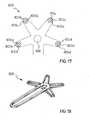
- Figs. 15 and 16show the progression of the continuous layers of structural fibres 413a, 413b, 413c, 413d for manufacturing a branched pedal crank, commonly referred to as a right pedal crank.
- the continuous layers of structural fibres 413a, 413b, 413c, 413dpartially surround the seats 405a, 405b, 405c, 405d of the end parts 403a, 403b, 403c, 403d of the spokes for an arc of circumference of about 180°.
- Such layersare each arranged in such a way as to form respective loops 415a, 415b, 415c, 415d which close on the central zone 414 where the pedal crank has a suitable seat 406 for the connection to the bottom bracket.
- the structural fibres thus arrangeddefine an intermediate product 400 which is star-shaped. As shown in fig. 15 , such an intermediate product 400 is advantageously made through continuous winding, along suitable paths, of continuous layers of unidirectional fibre.
- the intermediate product 400can be made directly inside the mould, for example inside the mould shown in fig. 14 , or else it can be made separately using a mask which mirrors the shape of the spokes.
- the manufacturing of the intermediate product 400separately allows a prior preheating of the fibres to be realised and allows them to be given a pre-shaping before the positioning in loco into the mould.
- the intermediate product 400is arranged inside the mould 200 on a plane overlapping the one in which the closed loop of structural fibres 15 (represented in fig. 2 ) is arranged, said fibres being arranged along the elongated body 2 of the pedal crank.
- the configuration thus obtainedallows a right pedal crank to be manufactured having simultaneously the zones intended for coupling with the pedal and with the bottom bracket and the ends of the spokes with high structural and mechanical continuity.
- each seat 405a, 405b, 405c, 405dcan be completely surrounded by structural fibres 413a, 413b, 413c, 413d by using a closed loop configuration of the type shown in fig. 5 .
- the same resultcan be obtained through the manufacturing of a pre-formed semi-finished product 500, as shown in figure 18 , where the continuous layers of structural fibres associated with the spokes and with the main body are on the same plane and substantially constitute a single element according to a comet-shape.
- the intermediate product 500can be manufactured directly inside the mould or else can be manufactured separately using a mask which mirrors the shape of the pedal crank.
Landscapes
- Engineering & Computer Science (AREA)
- Mechanical Engineering (AREA)
- Chemical & Material Sciences (AREA)
- Composite Materials (AREA)
- Textile Engineering (AREA)
- Combustion & Propulsion (AREA)
- Transportation (AREA)
- Moulding By Coating Moulds (AREA)
- Shafts, Cranks, Connecting Bars, And Related Bearings (AREA)
- Ropes Or Cables (AREA)
- Laminated Bodies (AREA)
Abstract
Description
- The present invention relates to a bicycle component particularly suitable for being used in the assemblage of bicycle parts where high specific pressures are to be dealt with.
- Throughout this patent description the component being referred to is a pedal crank, but what said can be extended to bicycle components which are different but which have characteristics similar to those of a pedal crank, like, for example, the seat tube.
- According to the prior art, different types of pedal crank can be identified, with different shapes, materials and constructive techniques in order to achieve the object of reducing the weight as much as possible and, at the same time, ensuring, if not even improving, the characteristics of strength and reliability of the pedal crank.
- The trend towards manufacturing lighter pedal cranks has led to the use of composite materials, in particular formed of sheets of plastic material made of resin, incorporating structural fibres. The structural fibres, indeed, considerably contribute to the structural strength of the pedal crank.
- A known solution which uses the aforementioned technique is shown in
EP 1 281 609 to the same Applicant, wherein the body of the pedal crank is obtained by moulding of a thermosetting composite material inside a mould in which metal inserts are arranged. - The composite material used in such a case is preferably of the type described in
US 4 339 490 and consists of sheets formed of a resin matrix in which oblong or other shaped small sheets of structural fibres are incorporated, of a size between 1 and 100 mm and orientated randomly into the sheet. The use of such a type of composite material for moulding provides for a good compromise between obtaining good strength characteristics, typical of the structural fibres, and the need to keep a sufficient fluidity during moulding. The size of the small sheets, indeed, allows the composite material to flow sufficiently uniformly inside the mould, creating a pedal crank body with characteristics of good homogeneity. - However, the use of composite material in small sheets of structural fibres gives rise to some drawbacks.
- A first drawback occurs during the moulding of the pedal crank, specifically in the end zones, where the metal inserts for the connection of the pedal crank to the bottom bracket and to the pedal are arranged.
- The moulding technique used, indeed, provides for arranging a predetermined amount of composite material in the central zone of the mould and, during the moulding step, making such a composite material flow until all of the mould is filled, even the end zones where the metal inserts are arranged. During the moulding step, the composite material goes around the metal inserts following two distinct flows which join together close to the end of the pedal crank, completely encasing the inserts.
- Disadvantageously, this causes a zone of discontinuity in the joint points of the two flows. Moreover, due to the greater fluidity of the resin with respect to that of the structural fibres and due to the long route (from the centre to the end of the mould), the end zones of the pedal crank have a greater percentage of resin with respect to the percentage in the rest of the pedal crank and, therefore, also lower strength with respect to the rest of the pedal crank.
- Since the end zones of the pedal crank are subjected to substantial stress during pedalling, the two aforementioned drawbacks can lead to undesired breaking of the pedal crank in such zones.
- Another drawback encountered in pedal cranks obtained by moulding of composite material of small sheets of structural fibres is the breaking of the pedal crank in its central zone. The occurrence of such a drawback is due to the fact that such a composite material with small sheets does not ensure sufficient strength in such a zone of the pedal crank.
- The invention relates to a bicycle component comprising an elongated body consisting of structural fibres incorporated in a matrix of polymeric material and having, in an end part thereof, a seat for mechanical coupling with an element of the bicycle, wherein in the zone between said seat and the end of said body there is at least one continuous layer of structural fibres at least partially surrounding said seat to ensure mechanical continuity in said zone,characterised in that said matrix of polymeric material comprises small sheets of structural fibres arranged randomly inside the matrix.
- Advantageously, the continuous layer of structural fibres gives high mechanical strength to the end zone of the pedal crank. In fact, it avoids the formation in such an end zone of discontinuities of structural fibres and a reduction in the percentage thereof with respect to resin.
- Advantageously, the combination between a layer of continuous structural fibres and a layer of structural fibres in small sheets, randomly arranged in the layer, allows the component to have excellent structural strength, whilst still leaving good fluidity to the resulting composite material.
- Further characteristics and advantages of the invention shall become clearer from the description of some preferred embodiments, given with reference to the attached drawings, where:
fig. 1 represents a schematic axonometric view of the component of the invention;fig. 2 represents a section view from above of the component offig. 1 ;fig. 3 represents a variant embodiment of the component offig. 1 ;fig. 4 represents a section view from above of the component offig. 3 ;fig. 5 represents another variant embodiment of the component offig. 1 ;figures 6 to 11 represent different axonometric views of the semi-finished product of the invention;fig. 12 represents an exploded axonometric view of the mould used for manufacturing the component of the invention;fig. 13 represents an axonometric view of a detail offig. 12 ;fig. 14 represents an exploded axonometric view of the mould used for manufacturing a variant of the component of the invention;fig. 15 represents an axonometric view of a variant embodiment relative to the progression of the continuous layers of structural fibres in a branched pedal crank;fig. 16 represents a plan view offig. 15 ;fig. 17 represents another variant relative to the progression of the continuous layers of structural fibres in a branched pedal crank;fig. 18 represents an axonometric view of a further variant embodiment relative to the progression of the continuous layers of structural fibres in a branched pedal crank.- The component of the invention, shown and described, is a pedal crank wholly indicated in
figs. 1 and 2 with 1. It essentially consists of anelongated body 2 formed of acomposite material 18, comprising small sheets of structural fibres incorporated in a matrix of polymeric material, the small sheets being arranged randomly, as it can be seen more clearly infig. 2 . The pedal crank 1 has, at itsend parts respective seats 5 and 6 for mechanical coupling with the bottom bracket and with the pedal of the bicycle. Theseats 5 and 6 incorporatecylindrical metal inserts - In a variant embodiment of the invention, the
seats 5 and 6 can consist of a hole of a suitable shape adapted to allow the direct connection of the pedal crank to the bottom bracket and to the pedal or else the subsequent insertion of metal inserts. - In the two
end zones 9 and 10 of the pedal crank 1, between theseats 5 and 6 and theends body 2 of the pedal crank 1, there are continuous layers ofstructural fibres end zones 9 and 10 of theseats 5 and 6. Such layers of continuousstructural fibres such end zones 9 and 10 there is structural and mechanical continuity. - As it can be observed in
fig. 1 , the continuous layers ofstructural fibres end 11 to the other 12 of the pedal crank 1. - As it can be clearly seen in
fig. 2 , the continuous layers ofstructural fibres end zones 9 and 10 of theseats 5 and 6, are realised in a single closedloop 15 of unidirectional fibres which extends longitudinally along thebody 2 of the pedal crank 1. In other cases, such a configuration could be different, like for example a series of unidirectional structural fibres surrounding the twoseats 5 and 6 according to a typical "8-shaped" configuration. - In
fig. 2 , the continuous layers ofstructural fibres end zones 9 and 10 and can, at most, also be reduced to a single layer. Moreover,such layers annular retainer element 16, coaxial to theinsert 7. - The arrangement of a limited number of
layers composite material 18 with which thebody 2 of the pedal crank 1 is made, as it can be seen more clearly infig. 2 . - A different solution is shown in
figures 3 and 4 , wherein the continuous layers ofstructural fibres end zones pedal crank 20. In this solution thecomposite material 38 with which thebody 2 of the pedal crank 1 is made is confined inside theloop 35 defined by the continuous layers offibres - In
fig. 5 a variant is shown of the arrangement of the continuous layers ofstructural fibres seats corresponding metal inserts - In different embodiments, not shown in the figures, the continuous layers of structural fibres can take different shapes and sizes. For example, such layers can extend, at the end zone, for all of the height H of the pedal crank 1. Moreover, such layers can be made of interwoven structural fibres according to at least two incident directions to make a fabric. In a preferred embodiment, such a fabric comprises a majority of fibres orientated according to a direction parallel to the middle plane of the pedal crank 1. Finally, it is possible that in further embodiments there are a plurality of continuous layers of structural fibres, according to any combination of the continuous layers described above.
- The pedal crank 1, and specifically its
elongated body 2, according to the invention, is formed with a semi-finished product, indicated with 60 infig. 6 , consisting of three layers. Onelayer 61, formed of small sheets ofstructural fibre 61a incorporated in a matrix of polymeric material and arranged randomly inside thelayer 61 and twolayers structural fibres layers semi-finished product 60 characteristics of structural strength through theunidirectional fibres structure 61a, this last characteristic being exploited in the moulding step of the pedal crank 1. - The arrangement and number of the layers, as well as the directions of the structural fibres, can be chosen according to the particular properties of structural strength of the component wished to be obtained.
- Thus, for example, in
fig. 7 thelayer 61 is arranged between the twolayers - The embodiment of
fig. 8 differs from that offig. 6 in that theunidirectional fibres respective layers 72 and 73 define complementary directions respectively orientated at +90° and 0°. - In
fig. 9 the semi-finished product has a layer of small sheets ofstructural fibres 61a incorporated in a matrix of polymeric material overlapping asingle layer 63 formed of continuousstructural fibres 63a orientated according to the +45° direction. - In
fig. 10 the semi-finished product has a layer of small sheets ofstructural fibres 61a and alayer 81 in which the continuousstructural fibres 81a are arranged according to two incident directions forming a fabric configuration. - Finally, in
fig. 11 a semi-finished product formed of five layers is shown. Twolayers layers - The
semi-finished product 60 used for manufacturing thebody 2 of the pedal crank 1, according to any of the illustrated embodiments and all other possible configurations, can also be rolled around a rolling axis before its use in the moulding step, as it shall be seen hereafter. This allows the characteristics of unidirectional strength of the structural fibres to be distributed in space. - With reference to
fig. 12 , hereafter the method for manufacturing the pedal crank 20 shown infig. 3 is described. However, it should be understood that the same method can be used for the other embodiments shown or described, for example those offigure 1 and 5 . - The method provides for the use of a
mould 100 formed by three parts, consisting of two half-shells plunger 103. The upper half-shell 102, as it can be seen more clearly in the bottom view thereof offig. 13 , has a through-opening 104 which allows the passage and the sliding of apresser element 105 of theplunger 103. - A first step of the method provides for the formation of the
intermediate product 110 consisting of theinserts closed loop configuration 35. Such anintermediate product 110 can be realised, for example, by winding a long fibre around theinserts insert 7 is defined through theretainer element 16 which confines them in an upper portion of theinsert 7. Experience has demonstrated, indeed, that it is precisely such a zone that is subjected to the greatest torsional stress during pedalling, thus requiring a greater structural strength. - The
intermediate product 110 thus obtained is placed inside the lower half-shell 101 above which the upper half-shell 102 is closed so that itsshapings - When the
mould 100 is closed, thesemi-finished product 60 previously wound around the rolling axis A is inserted in the throughopening 104. The winding of thesemi-finished product 60 is realised so that its outer surface consists of thelayer 63 formed ofunidirectional fibres 63a. Thesemi-finished product 60 is pre-heated to ease the subsequent moulding. - After its insertion in the
mould 100, the woundsemi-finished product 60 is then in the zone defined between theinserts loop 35. Theplunger 103 is lowered and thepresser 105 slides inside theopening 104 of the upper half-shell 102 determining a thrusting action of thesemi-finished product 60 inside themould 100. During such a moulding step, thesemi-finished product 60 uniformly fills the recess defined by the two half-shells closed loop configuration 35 of the unidirectional fibres allows them to keep their continuous configuration even during moulding, since the pressure forces applied by the composite material which constitutes thesemi-finished product 60 are uniformly distributed along theloop 35. When the action of thepresser 105 has ended, themould 100 is heated, according to known techniques, and the material inside of it polymerises thus realising the desired pedal crank structure. Finally, themould 100 is opened and the pedal crank is removed. - It is clear that for the described method any of the semi-finished products described above can be used, possibly even in non-wound configuration. If one wishes to manufacture the pedal crank according to the shape shown in
fig. 5 , it is then advisable for the intermediate product, in this case consisting of the inserts on which the unidirectional fibres are individually wound, to undergo a prepolymerisation treatment, so that the subsequent moulding does not modify the shape of the wound fibres. - In
fig. 14 a variant of the mould shown infig. 12 is shown which is used for manufacturing a branched pedal crank, commonly known as right pedal crank. Such a method differs from the previous one in that the semi-finished product, when inserted in themould 200, covers the top of the metal insert intended for coupling with the bottom bracket. In this case, the access to such a metal insert can take place by the subsequent removal of material through machining. Or else, instead of the metal insert a support can be used for the winding of the unidirectional fibres which remains incorporated in the pedal crank and then a seat can be formed, through machining, for direct coupling with the bottom bracket or the insertion of a metal insert. It is also clear that themould 200 can be modified so as to obtain a right pedal crank in which also the insert intended for coupling with the bottom bracket is immediately accessible. Figs. 15 and 16 show the progression of the continuous layers ofstructural fibres - In such a case it is desired to ensure high structural and mechanical continuity of the
end parts respective seats seats - As shown in the embodiment of the figures, the continuous layers of
structural fibres seats end parts respective loops central zone 414 where the pedal crank has asuitable seat 406 for the connection to the bottom bracket. - The structural fibres thus arranged define an
intermediate product 400 which is star-shaped. As shown infig. 15 , such anintermediate product 400 is advantageously made through continuous winding, along suitable paths, of continuous layers of unidirectional fibre. Theintermediate product 400 can be made directly inside the mould, for example inside the mould shown infig. 14 , or else it can be made separately using a mask which mirrors the shape of the spokes. The manufacturing of theintermediate product 400 separately allows a prior preheating of the fibres to be realised and allows them to be given a pre-shaping before the positioningin loco into the mould. - The
intermediate product 400 is arranged inside themould 200 on a plane overlapping the one in which the closed loop of structural fibres 15 (represented infig. 2 ) is arranged, said fibres being arranged along theelongated body 2 of the pedal crank. The configuration thus obtained allows a right pedal crank to be manufactured having simultaneously the zones intended for coupling with the pedal and with the bottom bracket and the ends of the spokes with high structural and mechanical continuity. - In a variant embodiment, shown in
fig. 17 , eachseat structural fibres fig. 5 . - The same result can be obtained through the manufacturing of a pre-formed
semi-finished product 500, as shown infigure 18 , where the continuous layers of structural fibres associated with the spokes and with the main body are on the same plane and substantially constitute a single element according to a comet-shape. As for the previous case, theintermediate product 500 can be manufactured directly inside the mould or else can be manufactured separately using a mask which mirrors the shape of the pedal crank.
Claims (15)
- Bicycle component (1; 20) comprising an elongated body (2) consisting of structural fibres incorporated in a matrix of polymeric material (18; 38) and having, in an end part thereof (3, 4; 403a, 403b, 403c, 403d), a seat (5, 6; 45, 46; 405a, 405b, 405c, 405d, 406) for mechanical coupling with an element of the bicycle, wherein in the zone (9, 10; 29, 30) between said seat (5, 6; 45, 46; 405a, 405b, 405c, 405d, 406) and the end (11, 12) of said body (2) there is at least one continuous layer of structural fibres (13, 14; 33, 34; 53, 54; 413a, 413b, 413c, 413d) at least partially surrounding said seat (5, 6; 45, 46; 405a, 405b, 405c, 405d, 406) to ensure mechanical continuity in said zone (9, 10; 29, 30),characterised in that said matrix of polymeric material comprises small sheets of structural fibres arranged randomly inside the matrix.
- Component (1; 20) according to claim 1,characterised in that said continuous layer of structural fibres is made of fibres interwoven according to at least two incident directions to make a fabric or is made of unidirectional fibres orientated according to a direction substantially parallel to the middle plane (π) of the component (1; 20).
- Component (1; 20) according to claim 2,characterised in that said continuous layer of structural fibres is made of fibres interwoven according to at least two incident directions to make a fabric and said fabric comprises a majority of fibres orientated according to a direction substantially parallel to the middle plane of the component.
- Component (1; 20) according to any of the previous claims,characterised in that it comprises a plurality of continuous layers of structural fibres (13, 14; 33, 34; 53, 54; 413a, 413b, 413c, 413d).
- Component (1; 20) according to any of the previous claims,characterised in that said continuous layer of structural fibres (33, 34; 413a, 413b, 413c, 413d) surrounds all of the zone (9, 10; 29, 30) between said seat (5, 6; 45, 46; 405a, 405b, 405c, 405d, 406) and said end (11, 12 or completely surrounds said seat (45, 46; 406).
- Component (1; 20) according to any of the previous claims,characterised in that said seat (5, 6; 45, 46; 405a, 405b, 405c, 405d, 406) consists of a hole adapted to accomplish the direct coupling with the element of the bicycle, or adapted to receive a metal insert (7, 8; 47, 48), or incorporating a metal insert (7, 8; 47, 48) adapted to accomplish the coupling with the element of the bicycle.
- Component (1; 20) according to any of the previous claims,characterised in that said continuous layer of structural fibres (13, 14; 33, 34; 53, 54; 413a, 413b, 413c, 413d) is confined in said end zone (9, 10; 29, 30) for part of the height (H) of the component (1; 20) or extends in said end zone (9, 10; 29, 30) for the whole height (H) of the component (1; 20).
- Component (1; 20) according to claim 7,characterised in that said continuous layer of structural fibres (13, 14; 33, 34; 53, 54; 413a, 413b, 413c, 413d) is confined in said end zone (9, 10; 29, 30) for part of the height (H) of the component (1; 20) by an annular retainer element (16).
- Component (1; 20) according to any of the previous claims,characterised in that said continuous layer of structural fibres (13, 14) is confined in said end zone (9, 10) for a part of its thickness (S1, S2) or extends in said end zone (29, 30) for its whole thickness (S1, S2).
- Component (1; 20) according to any of the previous claims,characterised in that it has, at its second end part (4, 3), a second seat (6, 5; 46, 45; 406) for the mechanical coupling with a second component of the bicycle andin that at the zone (10, 9; 30, 29) between said second seat (6, 5; 46, 45; 406) and said second end part (4, 3) there is at least one continuous layer of structural fibres (13, 14; 33, 34; 53, 54) at least partially surrounding said second seat (6, 5; 46, 45; 406) to ensure mechanical continuity in said zone (10, 9; 30, 29).
- Component (1; 20) according to claim 10,characterised in that said continuous layer of structural fibres (13, 14; 33, 34) surrounds said first and second seats (5, 6; 406) forming a closed loop (15; 35) or realising a substantially "8-shaped" configuration.
- Component (1; 20) according to claim 10 or 11,characterised in that it comprises one or more arms diverging from said elongated body which have, on their free end part (403a, 403b, 403c, 403d), third seats (405a, 405b, 405c, 405d) for the mechanical coupling with a third component of the bicycle andin that in at least one of the zones between said third seats (405a, 405b, 405c, 405d) and the respective end parts (403a, 403b, 403c, 403d) there is at least one continuous layer of structural fibres (413a, 413b, 413c, 413d) at least partially surrounding said third seats (405a, 405b, 405c, 405d) to ensure mechanical continuity in said zones.
- Component (1; 20) according to claim 12,characterised in that said continuous layer of structural fibres (413a, 413b, 413c, 413d) surrounds at least one of said third seats (405a, 405b, 405c, 405d) and said second seat (406) forming a closed loop (415a, 415b, 415c, 415d).
- Component (1; 20) according to claim 12 or 13,characterised in that said continuous layer of structural fibres (413a, 413b, 413c, 413d) surrounds each of said third seats (405a, 405b, 405c, 405d) and said second seat (406) according to a star-shaped configuration or simultaneously surrounds said third seats (405a, 405b, 405c, 405d), said second seat (406)and said first seat (5) according to a comet-shaped configuration.
- Component (1; 20) according to claim 12,characterised in that said continuous layer of structural fibres completely surrounds at least one of said third seats (405a, 405b, 405c, 405d).
Priority Applications (1)
| Application Number | Priority Date | Filing Date | Title |
|---|---|---|---|
| EP20090009916EP2110302A1 (en) | 2003-06-11 | 2003-08-01 | Bicycle component |
Applications Claiming Priority (3)
| Application Number | Priority Date | Filing Date | Title |
|---|---|---|---|
| EP03425378 | 2003-06-11 | ||
| EP20090009916EP2110302A1 (en) | 2003-06-11 | 2003-08-01 | Bicycle component |
| EP20030425530EP1486413B1 (en) | 2003-06-11 | 2003-08-01 | Method for manufacturing a bicycle component |
Related Parent Applications (1)
| Application Number | Title | Priority Date | Filing Date |
|---|---|---|---|
| EP20030425530DivisionEP1486413B1 (en) | 2001-02-13 | 2003-08-01 | Method for manufacturing a bicycle component |
Publications (1)
| Publication Number | Publication Date |
|---|---|
| EP2110302A1true EP2110302A1 (en) | 2009-10-21 |
Family
ID=33300992
Family Applications (3)
| Application Number | Title | Priority Date | Filing Date |
|---|---|---|---|
| EP20090009916CeasedEP2110302A1 (en) | 2003-06-11 | 2003-08-01 | Bicycle component |
| EP20090009915Expired - LifetimeEP2130756B1 (en) | 2003-06-11 | 2003-08-01 | Bicycle component and method for manufacturing such a component |
| EP20030425530Expired - LifetimeEP1486413B1 (en) | 2001-02-13 | 2003-08-01 | Method for manufacturing a bicycle component |
Family Applications After (2)
| Application Number | Title | Priority Date | Filing Date |
|---|---|---|---|
| EP20090009915Expired - LifetimeEP2130756B1 (en) | 2003-06-11 | 2003-08-01 | Bicycle component and method for manufacturing such a component |
| EP20030425530Expired - LifetimeEP1486413B1 (en) | 2001-02-13 | 2003-08-01 | Method for manufacturing a bicycle component |
Country Status (5)
| Country | Link |
|---|---|
| US (2) | US8024993B2 (en) |
| EP (3) | EP2110302A1 (en) |
| JP (1) | JP4836413B2 (en) |
| CN (1) | CN1572650B (en) |
| TW (2) | TWI391288B (en) |
Families Citing this family (55)
| Publication number | Priority date | Publication date | Assignee | Title |
|---|---|---|---|---|
| EP1486412B1 (en) | 2003-06-10 | 2014-05-07 | Campagnolo S.R.L. | Bicycle pedal crank |
| EP2110302A1 (en) | 2003-06-11 | 2009-10-21 | CAMPAGNOLO S.r.l. | Bicycle component |
| US20060012650A1 (en)* | 2004-04-12 | 2006-01-19 | Seiko Epson Corporation | Liquid-supplying member, liquid-injection apparatus, mounting method, fluid-carrying tube, and manufacturing method of fluid-carrying tube |
| EP1749736A1 (en)* | 2005-08-03 | 2007-02-07 | Campagnolo S.R.L. | Bicycle component of composite material with inserts and relative manufacturing process |
| EP1818252B1 (en) | 2006-02-14 | 2011-09-07 | CAMPAGNOLO S.r.l. | Bicycle pedal crank and method for manufactoring such a pedal crank |
| EP1818251A1 (en)* | 2006-02-14 | 2007-08-15 | CAMPAGNOLO S.r.l. | Bicycle pedal crank, intermediate product and method for manufacturing such a pedal crank |
| DE102006058377B4 (en)* | 2006-12-08 | 2010-09-16 | Airbus Deutschland Gmbh | Rod for the structural reinforcement of a fuselage structure of an aircraft |
| DE102008033621A1 (en)* | 2008-07-17 | 2010-01-21 | Volkswagen Ag | Plastic component for motor vehicles, comprises a reinforcing insert embedded in the component, where the reinforcing insert is formed by separate, pre-fabricated and preformed fabric inserts and/or mats made of aligned endless fibers |
| WO2012115599A2 (en)* | 2011-02-18 | 2012-08-30 | Mustafa Celik | Prestressed manufacturing and method of high strength composite upper and lower structural components |
| CA3100510A1 (en) | 2012-08-21 | 2014-02-27 | Vertera, Inc. | Systems and methods for making porous films, fibers, spheres, and other articles |
| ITMI20122229A1 (en)* | 2012-12-21 | 2014-06-22 | Campagnolo Srl | BICYCLE COMPONENT INCLUDING AN ALUMINUM BODY AND A COMPOSITE BODY, AND METHOD OF MANUFACTURING SUCH A COMPONENT |
| JP2014133446A (en)* | 2013-01-09 | 2014-07-24 | Nippon Light Metal Co Ltd | High intensity suspension parts for vehicle, and method for manufacturing the same |
| DE102014217215A1 (en)* | 2013-09-17 | 2015-03-19 | F&G Engineering Gmbh | Method for winding fiber composite components |
| DE102014103701B3 (en)* | 2014-03-18 | 2015-05-21 | Holger Faupel | Crank arm for a bicycle pedal crank system and manufacturing method therefor |
| US9498922B2 (en)* | 2014-06-26 | 2016-11-22 | Vertera, Inc. | Apparatus and process for producing porous devices |
| US9504550B2 (en) | 2014-06-26 | 2016-11-29 | Vertera, Inc. | Porous devices and processes for producing same |
| US10184510B2 (en)* | 2015-05-09 | 2019-01-22 | James Walter Linck | Method of making a carbon composite piston engine crankshaft |
| USD815281S1 (en) | 2015-06-23 | 2018-04-10 | Vertera, Inc. | Cervical interbody fusion device |
| US10562588B2 (en) | 2015-09-01 | 2020-02-18 | The Hive Global, Inc | Bicycle cassette with locking connection |
| FR3044119B1 (en)* | 2015-11-19 | 2017-12-29 | Carbody | PROCESS FOR MANUFACTURING COMPOSITE MATERIAL, PEDAL DEVICE FOR VEHICLE |
| WO2017165226A1 (en) | 2016-03-24 | 2017-09-28 | The Hive Global, Inc. | Bicycle crank with spindle attachment structure |
| GB201611862D0 (en)* | 2016-07-07 | 2016-08-24 | Williams Grand Prix Eng Ltd | A structural member |
| US11091217B2 (en)* | 2017-01-26 | 2021-08-17 | Giant Manufacturing Co., Ltd. | Joint structure of a composite bicycle frame and manufacturing method thereof |
| JP6708582B2 (en)* | 2017-04-10 | 2020-06-10 | トヨタ自動車株式会社 | Vehicle suspension arm |
| FR3067279B1 (en)* | 2017-06-13 | 2021-02-19 | Conseil & Technique | PROCESS FOR MAKING A PART IN COMPOSITE MATERIAL, AND COMPOSITE PART OBTAINED |
| CN107415572A (en)* | 2017-06-19 | 2017-12-01 | 厦门连科工业有限公司 | A kind of new spoke structure and its assembly method |
| DE102017113421A1 (en)* | 2017-06-19 | 2018-12-20 | Thyssenkrupp Ag | Method for producing a fiber composite component |
| DE102017213564A1 (en)* | 2017-08-04 | 2019-02-07 | Zf Friedrichshafen Ag | Three-point link and manufacturing method for a three-point link |
| US11351815B2 (en) | 2017-08-21 | 2022-06-07 | The Hive Global, Inc. | Bicycle cassette with clamping connection |
| DE102017128691B4 (en)* | 2017-12-04 | 2025-03-06 | Dr. Ing. H.C. F. Porsche Aktiengesellschaft | connecting strut |
| DE102017222579A1 (en)* | 2017-12-13 | 2019-06-13 | Schäfer MWN GmbH | Method for producing a component and component |
| FR3075408B1 (en)* | 2017-12-15 | 2020-01-10 | Carbody | BRAKE PEDAL DEVICE |
| IT201800005294A1 (en) | 2018-05-11 | 2019-11-11 | COMPONENT OF BICYCLE IN COMPOSITE MATERIAL AND RELATED MANUFACTURING PROCESS | |
| IT201800005299A1 (en) | 2018-05-11 | 2019-11-11 | BICYCLE COMPONENT EQUIPPED WITH STRESS / DEFORMATION SENSOR COMPENSATED FOR TEMPERATURE | |
| CA3042547A1 (en) | 2018-05-11 | 2019-11-11 | Campagnolo S.R.L. | Bicycle crankarm provided with electric/electronic system |
| IT201800005302A1 (en) | 2018-05-11 | 2019-11-11 | TRANSMISSION SIDE BICYCLE CRANK, EQUIPPED WITH STRESS / DEFORMATION DETECTOR FOR A TORQUE OR POWER METER, AS WELL AS RELATED METHODS | |
| IT201800005297A1 (en) | 2018-05-11 | 2019-11-11 | BICYCLE CRANK AND RELATIVE CRANKSET | |
| DE102018126998A1 (en)* | 2018-10-29 | 2020-04-30 | Boge Elastmetall Gmbh | Process for producing a handlebar or handlebar body from continuous fiber reinforced plastic |
| DE102019206436A1 (en)* | 2019-05-06 | 2020-11-12 | Schäfer MWN GmbH | Multipoint link for a chassis of a vehicle |
| DE102019206435A1 (en)* | 2019-05-06 | 2020-11-12 | Schäfer MWN GmbH | Multipoint link for a chassis of a vehicle |
| DE102019004341A1 (en)* | 2019-06-23 | 2020-12-24 | Albany Engineered Composites, Inc. | Rod head made of thermoplastic fiber-plastic composite (FRP) |
| US12117040B2 (en) | 2019-06-23 | 2024-10-15 | Albany Engineered Composites, Inc. | Rod end made of thermoplastic fiber-reinforced plastic |
| GB2587209A (en)* | 2019-09-18 | 2021-03-24 | Lentus Composites Ltd | Composite material panels |
| WO2021183966A1 (en)* | 2020-03-13 | 2021-09-16 | Galactic Co., LLC | Composite control cables and stabilizing tendons for aircraft applications and method for manufacture of same |
| TWI741649B (en)* | 2020-06-12 | 2021-10-01 | 世同金屬股份有限公司 | Composite crank and manufacturing method thereof |
| US11932351B2 (en) | 2020-07-17 | 2024-03-19 | The Hive Global, Inc. | Conical bicycle cassette sprocket structure |
| CN113043527B (en)* | 2021-02-09 | 2022-05-27 | 博戈橡胶塑料(株洲)有限公司 | Manufacturing method of lightweight composite thrust rod |
| CN113021939B (en)* | 2021-02-09 | 2022-04-22 | 博戈橡胶塑料(株洲)有限公司 | Manufacturing method of light-weight part based on continuous fibers and common fibers and product |
| US12233975B2 (en) | 2021-03-26 | 2025-02-25 | The Hive Global Inc. | Telescopic bicycle seatpost with adjustable height and fixed frame insertion |
| US12030586B2 (en) | 2021-07-12 | 2024-07-09 | The Hive Global, Inc. | Seal for bicycle crank with differential chainring motion |
| IT202100025118A1 (en)* | 2021-09-30 | 2023-03-30 | Piaggio & C Spa | MOTORCYCLE ASSEMBLY, MOTORCYCLE AND RELATED ASSEMBLY MANUFACTURING METHOD |
| TW202315797A (en)* | 2021-10-12 | 2023-04-16 | 美商速聯有限責任公司 | Bicycle crank arm |
| DE202022103016U1 (en) | 2022-05-29 | 2023-08-31 | Igus Gmbh | Pedal crank, in particular a bicycle pedal crank, with a plastic crank arm body |
| CN115123438A (en)* | 2022-06-27 | 2022-09-30 | 厦门市鑫和翔工贸有限公司 | Crank, manufacturing method of crank and mould for crank injection |
| DE102022129801A1 (en)* | 2022-11-10 | 2024-05-16 | MIRANDA & IRMÃO, LDª | Crank arm and crank arm assembly for a bicycle |
Citations (8)
| Publication number | Priority date | Publication date | Assignee | Title |
|---|---|---|---|---|
| US3080893A (en)* | 1956-06-29 | 1963-03-12 | Minnesota Mining & Mfg | Reinforced rigid plastic pipe |
| US4339490A (en) | 1979-09-12 | 1982-07-13 | Mitsubishi Rayon Company, Limited | Fiber reinforced plastic sheet molding compound |
| US4657795A (en)* | 1983-05-24 | 1987-04-14 | Technique Du Verre Tisse S.A. | Tubular material based on a fabric-reinforced resin, and a bicycle or similar vehicle frame constructed with such a material |
| US5271784A (en)* | 1992-12-18 | 1993-12-21 | Industrial Technology Research Institute | Method for manufacturing composite bicycle frames |
| US5435869A (en)* | 1993-08-27 | 1995-07-25 | Christensen; Roland | Method for manufacturing a composite crank arm |
| FR2722753A1 (en)* | 1994-07-25 | 1996-01-26 | Corima | Cycle saddle rod made of composite material |
| EP0916477A1 (en)* | 1997-11-13 | 1999-05-19 | Gilles Duqueine | Method for moulding a composite object, composite structure used in said process and apparatus for obtaining such composite structure |
| EP1281609A2 (en) | 2001-08-03 | 2003-02-05 | Campagnolo S.R.L. | Process for the production of a crank lever for a bicycle |
Family Cites Families (58)
| Publication number | Priority date | Publication date | Assignee | Title |
|---|---|---|---|---|
| GB1574825A (en) | 1976-03-31 | 1980-09-10 | Rubery Owen Fasteners Ltd | Screw threaded members and their manufacture |
| FR2416829A1 (en) | 1978-02-10 | 1979-09-07 | Gauthier Robert | Adjustable-length bicycle pedal crank - has orifice larger than pedal spindle to accommodate complementary component for securing spindle |
| DE2951111C2 (en) | 1979-12-19 | 1983-10-13 | Messerschmitt-Bölkow-Blohm GmbH, 8000 München | Connecting rods for prime movers |
| JPS57111694A (en) | 1980-12-27 | 1982-07-12 | Omron Tateisi Electronics Co | Device for treating card |
| JPS6022323A (en) | 1983-07-18 | 1985-02-04 | Rohm Co Ltd | Detection of passivation dry etching termination point |
| JPS60234762A (en)* | 1984-05-03 | 1985-11-21 | Toyoda Autom Loom Works Ltd | Method and device for producing fiber reinforced molding |
| JPS6166636A (en) | 1984-09-11 | 1986-04-05 | Mitsubishi Heavy Ind Ltd | Fiber reinforced plastic molded product and manufacture thereof |
| JPS61135801A (en) | 1984-12-06 | 1986-06-23 | Toray Ind Inc | Wheel |
| JPS61137634A (en) | 1984-12-07 | 1986-06-25 | Sugino Techno:Kk | Crank for bicycle and its production |
| ATE82921T1 (en)* | 1986-05-12 | 1992-12-15 | Brent J Trimble | PLASTIC BICYCLE FRAME COMPONENTS AND MANUFACTURING PROCESSES. |
| DE3763809D1 (en) | 1986-10-31 | 1990-08-23 | Look Sa | CRANK FOR BOTTOM BRACKETS OF A BICYCLE. |
| FR2612549B1 (en)* | 1987-03-20 | 1989-06-30 | Cahors App Elec | INSULATING ARM FOR ELECTRIC LINE SUPPORT POST AND MANUFACTURING METHOD THEREOF |
| US4900048A (en)* | 1987-10-02 | 1990-02-13 | Gleb Derujinsky | Integral seamless composite bicycle frame |
| US4856801A (en) | 1987-12-16 | 1989-08-15 | Cycle Composites, Inc. | Integral rear wheel suspension for composite material bicycle frame |
| FR2636386A1 (en)* | 1988-09-13 | 1990-03-16 | Peyrard | Elongate component of high mechanical strength, and its method of manufacture |
| JPH04339635A (en) | 1991-02-08 | 1992-11-26 | Sekisui Chem Co Ltd | Fiber-reinforced synthetic resin complex and its molding method |
| JP2567828B2 (en)* | 1991-04-03 | 1996-12-25 | 日東紡績株式会社 | Molding sheet material and safety shoe toecap |
| JPH04347006A (en) | 1991-05-24 | 1992-12-02 | Sumitomo Metal Ind Ltd | Fiber-reinforced plastic drive shaft |
| US5215322A (en) | 1991-12-10 | 1993-06-01 | Enders Mark L | Dual and single seat composite bicycle frames and fabrication methods therefore |
| US5624519A (en)* | 1992-05-29 | 1997-04-29 | Trek Bicycle, Corp. | Method making a composite bicycle frame using composite lugs |
| JPH06321167A (en) | 1993-05-14 | 1994-11-22 | Mitsubishi Rayon Co Ltd | Bicycle crank |
| US5632940A (en)* | 1994-03-29 | 1997-05-27 | Whatley; Bradford L. | Method of making an integrally stiffened article |
| DE29600548U1 (en) | 1996-01-13 | 1996-02-29 | Alfred Thun & Co GmbH, 58256 Ennepetal | Pedal crank for a bike |
| DE19601125C2 (en) | 1996-01-13 | 1999-01-28 | Thun Alfred & Co Gmbh | Pedal crank for a bike |
| CN2278644Y (en) | 1996-10-11 | 1998-04-15 | 王志宏 | bicycle crank structure |
| US5904072A (en) | 1996-12-20 | 1999-05-18 | Shimano Inc. | Bicycle crank arm |
| CN1062647C (en) | 1997-01-02 | 2001-02-28 | 林玉琴 | How the crank is made |
| US5851459A (en)* | 1997-03-31 | 1998-12-22 | Chen; Jason | Method for manufacturing cranks for bicycles |
| US6443033B1 (en) | 1997-04-11 | 2002-09-03 | Timothy Eugene Brummer | Two-piece bicycle crankset |
| US5941135A (en) | 1997-06-18 | 1999-08-24 | Schlanger; Raphael | Bicycle crankshaft assembly |
| US6324940B1 (en)* | 1997-08-13 | 2001-12-04 | Maclean-Fogg Company | Composite link |
| JPH11166552A (en) | 1997-12-08 | 1999-06-22 | Toho Rayon Co Ltd | Connecting structure between frp shaft and joint, and connecting method |
| US6265333B1 (en)* | 1998-06-02 | 2001-07-24 | Board Of Regents, University Of Nebraska-Lincoln | Delamination resistant composites prepared by small diameter fiber reinforcement at ply interfaces |
| US6268047B1 (en)* | 1999-01-22 | 2001-07-31 | Ppg Industries Ohio, Inc. | Glass fiber mats, laminates reinforced with the same and methods for making the same |
| US7070376B1 (en) | 1999-12-14 | 2006-07-04 | Simpson Strong-Tie Company, Inc. | Self-drilling, self-anchoring fastener for concrete |
| US6305243B1 (en)* | 2000-02-04 | 2001-10-23 | Douglas Chiang | Bicycle crank arm |
| CN2425848Y (en)* | 2000-05-12 | 2001-04-04 | 林珍妮 | bicycle crank |
| TW461866B (en)* | 2000-06-12 | 2001-11-01 | Advanced Int Multitech Co Ltd | Manufacture method of polymeric composite bicycle hollow crank |
| ITTO20010617A1 (en) | 2001-06-27 | 2002-12-27 | Campagnolo Srl | CRANK FOR BICYCLE AND PROCEDURE FOR ITS MANUFACTURE. |
| JP2003072666A (en) | 2001-06-27 | 2003-03-12 | Campagnolo Spa | Bicycle crank and its manufacturing method |
| ITTO20010621A1 (en) | 2001-06-27 | 2002-12-27 | Campagnolo Srl | CRANK FOR BICYCLE AND PROCEDURE FOR ITS MANUFACTURE. |
| CN2509074Y (en) | 2001-08-13 | 2002-09-04 | 明安国际企业股份有限公司 | Bicycle Hollow Crank of Polymer Composite Material |
| US20030061900A1 (en) | 2001-09-28 | 2003-04-03 | Smith Garrett Andrew | Bicycle crank pedal insert |
| US8071491B2 (en)* | 2001-11-07 | 2011-12-06 | FledForm Technologies, LLC | Process, composition and coating of laminate material |
| EP1350714A1 (en) | 2002-03-19 | 2003-10-08 | Campagnolo Srl | Hollow crank arm for a bicycle, and process for manufacturing the same |
| US6924021B1 (en)* | 2002-07-03 | 2005-08-02 | Trek Bicycle Corporation | Complex-shaped carbon fiber structural member and its method of manufacture |
| US6564675B1 (en)* | 2002-07-23 | 2003-05-20 | Cheng-Xun Jiang | Crank arm for bicycles |
| EP1419961A1 (en) | 2002-11-15 | 2004-05-19 | IPA N.V.-Composites | Hollow crank arm for bicycle |
| US7503239B2 (en) | 2003-01-30 | 2009-03-17 | Shimano Inc. | Bicycle crank arm assembly |
| US20040177717A1 (en) | 2003-03-13 | 2004-09-16 | Cheng-Hsun Chiang | Bicycle crank |
| EP1486412B1 (en) | 2003-06-10 | 2014-05-07 | Campagnolo S.R.L. | Bicycle pedal crank |
| EP2110302A1 (en) | 2003-06-11 | 2009-10-21 | CAMPAGNOLO S.r.l. | Bicycle component |
| EP1506882B1 (en)* | 2003-08-11 | 2008-07-09 | Campagnolo Srl | Composite bicycle rim and method for producing it |
| US7309668B2 (en)* | 2003-12-03 | 2007-12-18 | Elk Premium Building Products, Inc. | Multiple layer directionally oriented nonwoven fiber material and methods of manufacturing same |
| JP2006007799A (en) | 2004-06-22 | 2006-01-12 | Shimano Inc | Sprocket for bicycle |
| EP1818251A1 (en) | 2006-02-14 | 2007-08-15 | CAMPAGNOLO S.r.l. | Bicycle pedal crank, intermediate product and method for manufacturing such a pedal crank |
| EP1818252B1 (en) | 2006-02-14 | 2011-09-07 | CAMPAGNOLO S.r.l. | Bicycle pedal crank and method for manufactoring such a pedal crank |
| EP1840022B1 (en) | 2006-03-29 | 2010-03-03 | CAMPAGNOLO S.r.l. | Bicycle pedal crank assembly and related elements |
- 2003
- 2003-08-01EPEP20090009916patent/EP2110302A1/ennot_activeCeased
- 2003-08-01EPEP20090009915patent/EP2130756B1/ennot_activeExpired - Lifetime
- 2003-08-01EPEP20030425530patent/EP1486413B1/ennot_activeExpired - Lifetime
- 2004
- 2004-06-04TWTW98146465Apatent/TWI391288B/ennot_activeIP Right Cessation
- 2004-06-04TWTW93116194Apatent/TWI326661B/ennot_activeIP Right Cessation
- 2004-06-04USUS10/861,206patent/US8024993B2/ennot_activeExpired - Fee Related
- 2004-06-10JPJP2004173152Apatent/JP4836413B2/ennot_activeExpired - Fee Related
- 2004-06-11CNCN2004100493679Apatent/CN1572650B/ennot_activeExpired - Fee Related
- 2011
- 2011-09-26USUS13/245,351patent/US10105916B2/ennot_activeExpired - Fee Related
Patent Citations (8)
| Publication number | Priority date | Publication date | Assignee | Title |
|---|---|---|---|---|
| US3080893A (en)* | 1956-06-29 | 1963-03-12 | Minnesota Mining & Mfg | Reinforced rigid plastic pipe |
| US4339490A (en) | 1979-09-12 | 1982-07-13 | Mitsubishi Rayon Company, Limited | Fiber reinforced plastic sheet molding compound |
| US4657795A (en)* | 1983-05-24 | 1987-04-14 | Technique Du Verre Tisse S.A. | Tubular material based on a fabric-reinforced resin, and a bicycle or similar vehicle frame constructed with such a material |
| US5271784A (en)* | 1992-12-18 | 1993-12-21 | Industrial Technology Research Institute | Method for manufacturing composite bicycle frames |
| US5435869A (en)* | 1993-08-27 | 1995-07-25 | Christensen; Roland | Method for manufacturing a composite crank arm |
| FR2722753A1 (en)* | 1994-07-25 | 1996-01-26 | Corima | Cycle saddle rod made of composite material |
| EP0916477A1 (en)* | 1997-11-13 | 1999-05-19 | Gilles Duqueine | Method for moulding a composite object, composite structure used in said process and apparatus for obtaining such composite structure |
| EP1281609A2 (en) | 2001-08-03 | 2003-02-05 | Campagnolo S.R.L. | Process for the production of a crank lever for a bicycle |
Also Published As
| Publication number | Publication date |
|---|---|
| CN1572650A (en) | 2005-02-02 |
| EP1486413B1 (en) | 2010-04-28 |
| TW201016540A (en) | 2010-05-01 |
| EP1486413A3 (en) | 2004-12-29 |
| TWI391288B (en) | 2013-04-01 |
| US8024993B2 (en) | 2011-09-27 |
| TWI326661B (en) | 2010-07-01 |
| EP2130756A1 (en) | 2009-12-09 |
| US20050012298A1 (en) | 2005-01-20 |
| JP4836413B2 (en) | 2011-12-14 |
| EP1486413A2 (en) | 2004-12-15 |
| TW200502130A (en) | 2005-01-16 |
| EP2130756B1 (en) | 2012-10-03 |
| CN1572650B (en) | 2010-04-28 |
| US10105916B2 (en) | 2018-10-23 |
| JP2005001662A (en) | 2005-01-06 |
| US20120064284A1 (en) | 2012-03-15 |
Similar Documents
| Publication | Publication Date | Title |
|---|---|---|
| EP2110302A1 (en) | Bicycle component | |
| US4828285A (en) | Bicycle fork or similar article based on a resin reinforced by a textile structure and process for manufacturing same | |
| TWI389817B (en) | Bicycle crank arm, intermediate product and method for manufacturing such a crank arm | |
| RU2379185C1 (en) | Method of production of rod from composite material | |
| US7000499B2 (en) | Bicycle crank and method for manufacturing said crank | |
| DE102012023321B4 (en) | Bicycle assembly with bottom bracket shell | |
| EP1486412B1 (en) | Bicycle pedal crank | |
| US9487058B2 (en) | Composite structural element, particularly for a vehicle suspension, and method for manufacturing the same | |
| US7013753B2 (en) | Bicycle crank and method for manufacturing said crank | |
| EP1818251A1 (en) | Bicycle pedal crank, intermediate product and method for manufacturing such a pedal crank | |
| US7793959B2 (en) | Customizable carbon frames for bicycle or other vehicles | |
| CN100333964C (en) | Hollow crank arm for bicycle and method of manufacturing same | |
| WO2003024185A2 (en) | High performance bicycle crank | |
| JP5342065B2 (en) | Method for manufacturing a composite rod having reinforced ends | |
| CN101565080B (en) | Bicycle component and method for manufacturing such a component | |
| DE19846824C1 (en) | Steering wheel for motor vehicle | |
| KR102391001B1 (en) | Coil spring of complex material and manufacturing method thereof |
Legal Events
| Date | Code | Title | Description |
|---|---|---|---|
| PUAI | Public reference made under article 153(3) epc to a published international application that has entered the european phase | Free format text:ORIGINAL CODE: 0009012 | |
| AC | Divisional application: reference to earlier application | Ref document number:1486413 Country of ref document:EP Kind code of ref document:P | |
| AK | Designated contracting states | Kind code of ref document:A1 Designated state(s):AT BE BG CH CY CZ DE DK EE ES FI FR GB GR HU IE IT LI LU MC NL PT RO SE SI SK TR | |
| RIN1 | Information on inventor provided before grant (corrected) | Inventor name:FELTRIN, MAURI Inventor name:DETTORI, PAOLO Inventor name:DAL PRA', GIUSEPPE | |
| 17P | Request for examination filed | Effective date:20091216 | |
| 17Q | First examination report despatched | Effective date:20100119 | |
| APBK | Appeal reference recorded | Free format text:ORIGINAL CODE: EPIDOSNREFNE | |
| APBN | Date of receipt of notice of appeal recorded | Free format text:ORIGINAL CODE: EPIDOSNNOA2E | |
| APBR | Date of receipt of statement of grounds of appeal recorded | Free format text:ORIGINAL CODE: EPIDOSNNOA3E | |
| APAF | Appeal reference modified | Free format text:ORIGINAL CODE: EPIDOSCREFNE | |
| APBT | Appeal procedure closed | Free format text:ORIGINAL CODE: EPIDOSNNOA9E | |
| STAA | Information on the status of an ep patent application or granted ep patent | Free format text:STATUS: THE APPLICATION HAS BEEN REFUSED | |
| 18R | Application refused | Effective date:20120907 |