EP2108324B1 - Device for producing a hardenable mass - Google Patents
Device for producing a hardenable massDownload PDFInfo
- Publication number
- EP2108324B1 EP2108324B1EP09158716.2AEP09158716AEP2108324B1EP 2108324 B1EP2108324 B1EP 2108324B1EP 09158716 AEP09158716 AEP 09158716AEP 2108324 B1EP2108324 B1EP 2108324B1
- Authority
- EP
- European Patent Office
- Prior art keywords
- mixing
- container
- mass
- screw
- space
- Prior art date
- Legal status (The legal status is an assumption and is not a legal conclusion. Google has not performed a legal analysis and makes no representation as to the accuracy of the status listed.)
- Expired - Lifetime
Links
Images


Classifications
- B—PERFORMING OPERATIONS; TRANSPORTING
- B01—PHYSICAL OR CHEMICAL PROCESSES OR APPARATUS IN GENERAL
- B01F—MIXING, e.g. DISSOLVING, EMULSIFYING OR DISPERSING
- B01F33/00—Other mixers; Mixing plants; Combinations of mixers
- B01F33/50—Movable or transportable mixing devices or plants
- B01F33/501—Movable mixing devices, i.e. readily shifted or displaced from one place to another, e.g. portable during use
- B01F33/5011—Movable mixing devices, i.e. readily shifted or displaced from one place to another, e.g. portable during use portable during use, e.g. hand-held
- B01F33/50112—Movable mixing devices, i.e. readily shifted or displaced from one place to another, e.g. portable during use portable during use, e.g. hand-held of the syringe or cartridge type
- A—HUMAN NECESSITIES
- A61—MEDICAL OR VETERINARY SCIENCE; HYGIENE
- A61F—FILTERS IMPLANTABLE INTO BLOOD VESSELS; PROSTHESES; DEVICES PROVIDING PATENCY TO, OR PREVENTING COLLAPSING OF, TUBULAR STRUCTURES OF THE BODY, e.g. STENTS; ORTHOPAEDIC, NURSING OR CONTRACEPTIVE DEVICES; FOMENTATION; TREATMENT OR PROTECTION OF EYES OR EARS; BANDAGES, DRESSINGS OR ABSORBENT PADS; FIRST-AID KITS
- A61F2/00—Filters implantable into blood vessels; Prostheses, i.e. artificial substitutes or replacements for parts of the body; Appliances for connecting them with the body; Devices providing patency to, or preventing collapsing of, tubular structures of the body, e.g. stents
- A61F2/02—Prostheses implantable into the body
- A61F2/30—Joints
- A61F2/46—Special tools for implanting artificial joints
- B—PERFORMING OPERATIONS; TRANSPORTING
- B01—PHYSICAL OR CHEMICAL PROCESSES OR APPARATUS IN GENERAL
- B01F—MIXING, e.g. DISSOLVING, EMULSIFYING OR DISPERSING
- B01F33/00—Other mixers; Mixing plants; Combinations of mixers
- B01F33/50—Movable or transportable mixing devices or plants
- B01F33/501—Movable mixing devices, i.e. readily shifted or displaced from one place to another, e.g. portable during use
- A—HUMAN NECESSITIES
- A61—MEDICAL OR VETERINARY SCIENCE; HYGIENE
- A61B—DIAGNOSIS; SURGERY; IDENTIFICATION
- A61B17/00—Surgical instruments, devices or methods
- A61B17/56—Surgical instruments or methods for treatment of bones or joints; Devices specially adapted therefor
- A61B17/58—Surgical instruments or methods for treatment of bones or joints; Devices specially adapted therefor for osteosynthesis, e.g. bone plates, screws or setting implements
- A61B17/88—Osteosynthesis instruments; Methods or means for implanting or extracting internal or external fixation devices
- A61B17/8802—Equipment for handling bone cement or other fluid fillers
- A61B17/8805—Equipment for handling bone cement or other fluid fillers for introducing fluid filler into bone or extracting it
- A61B17/8816—Equipment for handling bone cement or other fluid fillers for introducing fluid filler into bone or extracting it characterised by the conduit, e.g. tube, along which fluid flows into the body or by conduit connections
- A—HUMAN NECESSITIES
- A61—MEDICAL OR VETERINARY SCIENCE; HYGIENE
- A61B—DIAGNOSIS; SURGERY; IDENTIFICATION
- A61B17/00—Surgical instruments, devices or methods
- A61B17/56—Surgical instruments or methods for treatment of bones or joints; Devices specially adapted therefor
- A61B17/58—Surgical instruments or methods for treatment of bones or joints; Devices specially adapted therefor for osteosynthesis, e.g. bone plates, screws or setting implements
- A61B17/88—Osteosynthesis instruments; Methods or means for implanting or extracting internal or external fixation devices
- A61B17/8802—Equipment for handling bone cement or other fluid fillers
- A61B17/8805—Equipment for handling bone cement or other fluid fillers for introducing fluid filler into bone or extracting it
- A61B17/8827—Equipment for handling bone cement or other fluid fillers for introducing fluid filler into bone or extracting it with filtering, degassing, venting or pressure relief means
- A—HUMAN NECESSITIES
- A61—MEDICAL OR VETERINARY SCIENCE; HYGIENE
- A61B—DIAGNOSIS; SURGERY; IDENTIFICATION
- A61B17/00—Surgical instruments, devices or methods
- A61B17/56—Surgical instruments or methods for treatment of bones or joints; Devices specially adapted therefor
- A61B17/58—Surgical instruments or methods for treatment of bones or joints; Devices specially adapted therefor for osteosynthesis, e.g. bone plates, screws or setting implements
- A61B17/88—Osteosynthesis instruments; Methods or means for implanting or extracting internal or external fixation devices
- A61B17/8802—Equipment for handling bone cement or other fluid fillers
- A61B17/8833—Osteosynthesis tools specially adapted for handling bone cement or fluid fillers; Means for supplying bone cement or fluid fillers to introducing tools, e.g. cartridge handling means
- A—HUMAN NECESSITIES
- A61—MEDICAL OR VETERINARY SCIENCE; HYGIENE
- A61M—DEVICES FOR INTRODUCING MEDIA INTO, OR ONTO, THE BODY; DEVICES FOR TRANSDUCING BODY MEDIA OR FOR TAKING MEDIA FROM THE BODY; DEVICES FOR PRODUCING OR ENDING SLEEP OR STUPOR
- A61M5/00—Devices for bringing media into the body in a subcutaneous, intra-vascular or intramuscular way; Accessories therefor, e.g. filling or cleaning devices, arm-rests
- A61M5/178—Syringes
- A61M5/31—Details
- A61M5/315—Pistons; Piston-rods; Guiding, blocking or restricting the movement of the rod or piston; Appliances on the rod for facilitating dosing ; Dosing mechanisms
- B—PERFORMING OPERATIONS; TRANSPORTING
- B01—PHYSICAL OR CHEMICAL PROCESSES OR APPARATUS IN GENERAL
- B01F—MIXING, e.g. DISSOLVING, EMULSIFYING OR DISPERSING
- B01F31/00—Mixers with shaking, oscillating, or vibrating mechanisms
- B—PERFORMING OPERATIONS; TRANSPORTING
- B01—PHYSICAL OR CHEMICAL PROCESSES OR APPARATUS IN GENERAL
- B01F—MIXING, e.g. DISSOLVING, EMULSIFYING OR DISPERSING
- B01F31/00—Mixers with shaking, oscillating, or vibrating mechanisms
- B01F31/44—Mixers with shaking, oscillating, or vibrating mechanisms with stirrers performing an oscillatory, vibratory or shaking movement
- B01F31/441—Mixers with shaking, oscillating, or vibrating mechanisms with stirrers performing an oscillatory, vibratory or shaking movement performing a rectilinear reciprocating movement
- B—PERFORMING OPERATIONS; TRANSPORTING
- B01—PHYSICAL OR CHEMICAL PROCESSES OR APPARATUS IN GENERAL
- B01F—MIXING, e.g. DISSOLVING, EMULSIFYING OR DISPERSING
- B01F33/00—Other mixers; Mixing plants; Combinations of mixers
- B01F33/70—Mixers specially adapted for working at sub- or super-atmospheric pressure, e.g. combined with de-foaming
- B—PERFORMING OPERATIONS; TRANSPORTING
- B01—PHYSICAL OR CHEMICAL PROCESSES OR APPARATUS IN GENERAL
- B01F—MIXING, e.g. DISSOLVING, EMULSIFYING OR DISPERSING
- B01F35/00—Accessories for mixers; Auxiliary operations or auxiliary devices; Parts or details of general application
- B01F35/71—Feed mechanisms
- B01F35/713—Feed mechanisms comprising breaking packages or parts thereof, e.g. piercing or opening sealing elements between compartments or cartridges
- B—PERFORMING OPERATIONS; TRANSPORTING
- B01—PHYSICAL OR CHEMICAL PROCESSES OR APPARATUS IN GENERAL
- B01F—MIXING, e.g. DISSOLVING, EMULSIFYING OR DISPERSING
- B01F35/00—Accessories for mixers; Auxiliary operations or auxiliary devices; Parts or details of general application
- B01F35/75—Discharge mechanisms
- B01F35/754—Discharge mechanisms characterised by the means for discharging the components from the mixer
- B01F35/75425—Discharge mechanisms characterised by the means for discharging the components from the mixer using pistons or plungers
- B01F35/754251—Discharge mechanisms characterised by the means for discharging the components from the mixer using pistons or plungers reciprocating in the mixing receptacle
- B—PERFORMING OPERATIONS; TRANSPORTING
- B29—WORKING OF PLASTICS; WORKING OF SUBSTANCES IN A PLASTIC STATE IN GENERAL
- B29B—PREPARATION OR PRETREATMENT OF THE MATERIAL TO BE SHAPED; MAKING GRANULES OR PREFORMS; RECOVERY OF PLASTICS OR OTHER CONSTITUENTS OF WASTE MATERIAL CONTAINING PLASTICS
- B29B7/00—Mixing; Kneading
- B29B7/002—Methods
- B29B7/005—Methods for mixing in batches
- B—PERFORMING OPERATIONS; TRANSPORTING
- B29—WORKING OF PLASTICS; WORKING OF SUBSTANCES IN A PLASTIC STATE IN GENERAL
- B29B—PREPARATION OR PRETREATMENT OF THE MATERIAL TO BE SHAPED; MAKING GRANULES OR PREFORMS; RECOVERY OF PLASTICS OR OTHER CONSTITUENTS OF WASTE MATERIAL CONTAINING PLASTICS
- B29B7/00—Mixing; Kneading
- B29B7/02—Mixing; Kneading non-continuous, with mechanical mixing or kneading devices, i.e. batch type
- B29B7/22—Component parts, details or accessories; Auxiliary operations
- B29B7/26—Component parts, details or accessories; Auxiliary operations for discharging, e.g. doors
- A—HUMAN NECESSITIES
- A61—MEDICAL OR VETERINARY SCIENCE; HYGIENE
- A61F—FILTERS IMPLANTABLE INTO BLOOD VESSELS; PROSTHESES; DEVICES PROVIDING PATENCY TO, OR PREVENTING COLLAPSING OF, TUBULAR STRUCTURES OF THE BODY, e.g. STENTS; ORTHOPAEDIC, NURSING OR CONTRACEPTIVE DEVICES; FOMENTATION; TREATMENT OR PROTECTION OF EYES OR EARS; BANDAGES, DRESSINGS OR ABSORBENT PADS; FIRST-AID KITS
- A61F2/00—Filters implantable into blood vessels; Prostheses, i.e. artificial substitutes or replacements for parts of the body; Appliances for connecting them with the body; Devices providing patency to, or preventing collapsing of, tubular structures of the body, e.g. stents
- A61F2/02—Prostheses implantable into the body
- A61F2/30—Joints
- A61F2/46—Special tools for implanting artificial joints
- A61F2002/4685—Special tools for implanting artificial joints by means of vacuum
- A—HUMAN NECESSITIES
- A61—MEDICAL OR VETERINARY SCIENCE; HYGIENE
- A61M—DEVICES FOR INTRODUCING MEDIA INTO, OR ONTO, THE BODY; DEVICES FOR TRANSDUCING BODY MEDIA OR FOR TAKING MEDIA FROM THE BODY; DEVICES FOR PRODUCING OR ENDING SLEEP OR STUPOR
- A61M5/00—Devices for bringing media into the body in a subcutaneous, intra-vascular or intramuscular way; Accessories therefor, e.g. filling or cleaning devices, arm-rests
- A61M5/178—Syringes
- A61M5/31—Details
- A61M5/315—Pistons; Piston-rods; Guiding, blocking or restricting the movement of the rod or piston; Appliances on the rod for facilitating dosing ; Dosing mechanisms
- A61M5/31596—Pistons; Piston-rods; Guiding, blocking or restricting the movement of the rod or piston; Appliances on the rod for facilitating dosing ; Dosing mechanisms comprising means for injection of two or more media, e.g. by mixing
- B—PERFORMING OPERATIONS; TRANSPORTING
- B01—PHYSICAL OR CHEMICAL PROCESSES OR APPARATUS IN GENERAL
- B01F—MIXING, e.g. DISSOLVING, EMULSIFYING OR DISPERSING
- B01F2101/00—Mixing characterised by the nature of the mixed materials or by the application field
- B01F2101/20—Mixing of ingredients for bone cement
Definitions
- the present inventionrelates to a system for producing a hardenable mass, preferably bone substitute and/or bone reinforcing material or bone cement or similar material, said system including a mixing container having a mixing space in which at least one powder and at least one liquid component are mixed to produce the hardenable mass and in which a piston means is provided to discharge the hardenable mass from said mixing space.
- a hardenable masspreferably bone substitute and/or bone reinforcing material or bone cement or similar material
- a mixing containerhaving a mixing space in which at least one powder and at least one liquid component are mixed to produce the hardenable mass and in which a piston means is provided to discharge the hardenable mass from said mixing space.
- Vertebroplastyis a percutaneous injection of bone cement into a vertebra in order to alleviate pain in a compression fracture caused by osteoporosis. Vertebroplasty was performed for the first time in France in 1984 and ten years later in the USA. Kyphoplasty means balloon expansion in a collapsed vertebra for, if possible, reducing the risk for further collapse of the vertebra and provide a cavity which is filled with bone cement.
- Kyphoplastyis regarded as experimental in Europe, but has recently been approved by the FDA for treatment of pathological fractures together with polymeric bone cements.
- the drawback with kyphoplastyis that this method requires general anaesthesia. Vertebroplasty however, can be performed in a surgery in fluoroscopy while administering sedatives and analgesics. Both methods give satisfactory pain relief in more than 75% of the cases. Early treatment of vertebra compression with vertebroplasty is still discussed even if satisfactory pain relief can be provided. It is recommended to wait at least six weeks before vertebroplasty is performed. While waiting, pain killing treatment is tested. Early treatment with vertebroplasty however, can be considered if there is a risk for complications causing immobilization or if the pain is severe. A principal object with vertebroplasty is except pain relief to prevent further collapse of vertebra. For identifying fractures, MR can be used besides common X-ray, said MR also showing oedema in the bone marrow and fracture gaps in the vertebra.
- Vertebroplastyis performed with the patient lying on his or her stomach or on the side during intraveneous sedation and pain relief and under control by a physician.
- a needleis inserted into a mandrine in the vertebra during fluoroscopy via a transpedicular or posteolateral inlet.
- the needleshall be positioned in the centre line, preferably in the fore or anterior part of the vertebra.
- injection of cementis carried through.
- Another needleis often necessary for symmetric filling of the vertebra.
- the injection of cementis carefully supervised via TV-fluoroscopy and if leakage occurs outside the limits of the vertebra, the injection is interrupted.
- the required volume for adequate pain reliefis small, about 2-3 ml.
- Screw devicesare already known from e.g US 2003/040718 , WO 93/14799 , US 2003/018339 and GB 2338428 . All but one prior art screw device according to these publications however, are no devices adapted for direct connection to a mixing container for discharge of hardenable mass from said mixing container. Mixing of the hardenable mass has either already been performed in another device and the hardenable mass has then been placed in a container therefor or, when in the one case mixing is performed, the mixing container is placed in a special holder with a screw device for discharge of the hardenable mass.
- the object of the present inventionis to provide a simple screw device permitting simple handling in connection with vertebroplasty and similar. This is arrived at by providing a system for producing a hardenable mass as defined in claim 1.
- the device 1 illustrated in the drawingsis adapted for producing a hardenable mass 2 such as bone substitute and/or bone reinforcing material or bone cement or similar material.
- This mass 2shall be fed and/or sucked out of the device 1 and comprises a mixing container 3 of e.g. cylindrical shape.
- the mixing container 3defines a mixing space 4 in which at least one powder component 5 and at least one liquid component 6 are mixed to produce the hardenable mass 2.
- a piston means 7which is adapted to be retained relative to the mixing container 3 during a mixing step and thereafter released such that it can move in the mixing space 4 relative to the mixing container 3.
- a rotatable means 8which in a retaining position P1 retains the piston means 7 relative to the mixing container 3 and which by rotation from the retaining position P1 to a release position P2 can be released relative to the mixing container 3, whereby the piston means 7 can move in the mixing space 4.
- the piston means 7 and the rotatable means 8are preferably directly or indirectly interconnected.
- the device 1preferably but not necessarily comprises a mixing means 9 which is provided for mixing the powder and liquid components 5, 6 with each other until the hardenable mass 2 has been produced. Then, the mass 2 can be stirred with the mixing means 9 if this is appropriate or necessary.
- the mixing means 9may comprise an elongated member 10, e.g. a hollow or solid rod, which extends into the mixing space 4 and which at an inner end within the mixing space 4 has a mixing disc 11 with axial holes 12 passing through said disc. At an outer end outside the mixing space 4, the elongated member 10 is provided with an operating handle 13 for operating the mixing means 9.
- the mixing/stirringcan be carried through in a known manner by moving the mixing means 9 back and forth in the mixing space 4 and preferably also rotating it relative to said mixing space 4.
- the piston means 7preferably has an axial hole 14 extending therethrough and by means of which the elongated member 10 of the mixing means 9 extends into the mixing space 4.
- the elongated member 10cooperates with the piston means 7 through one or more sealing rings 15 or similar, such that a sealing is provided between said members.
- the elongated member 10 and the hole 14 of the piston means 7are adapted to each other such that said elongated member 10 can be moved and rotated relative to the piston means 7.
- At least one outer sealing 16 or similaris provided on the piston means 7 for cooperation with the inner side of the mixing container 3 such that a sealing is defined between the piston means 7 and said inner side.
- the outer sealing ring 16is preferably designed such that it removes mass 2 which deposits on the inner side of the mixing container 3 when it moves in the mixing space 4.
- the piston means 7may also have an opening 17 with at least one filter 18.
- the opening 17is adapted to let out gases from the mixing space 4 and the filter 18 is adapted to prevent the components 5 and/or 6 and the mixed mass 2 from forcing its way out of the mixing space 4 through the opening 17.
- a rotary-movement preventing member 19is provided on the piston means 7.
- This member 19is annular and includes two axially provided hook portions 20, 21 which can be inserted into grooves 22, 23 in the piston means 7 and hooked onto two shoulders 7a, 7b thereon in a radial direction. By means of this positioning, the rotary-movement preventing member 19 is attached to the piston means 7 and can not rotate relative to said means.
- the rotary-movement preventing member 19further includes an axially provided flange 24 which is adapted to cooperate with a bracket 25 in order to prevent rotation of the rotary--movement preventing member 19 and thus, the piston means 7, relative to the bracket 25 such that the mixing means 9 is rotated relative to the piston means 7 for mixing of the powder and liquid components 5, 6.
- the bracket 25has a cylindrical member 27 with a hole 28 into which the rotatable means 8 can be inserted and through which said rotatable means can move when it is set in a release position P2.
- the cylindrical member 27 of the bracket 25may have an annular snap-in portion 29 which can be threaded into one or more locking portions 30 which are located at the inner side of the mixing container 3 and which allow the bracket 25 to be attached to the mixing container 3 by a snap-in closure.
- the bracket 25may have a number of radially projecting members 33, 34 which can be attached to a radially outwards directed flange 35 on the mixing container 3 by a snap-in closure such that the bracket 25 can not rotate relative to said container.
- the rotatable means 8has a through hole 8a through which the elongated member 10 of the mixing means 9 extends such that said elongated member 10 is movable relative to the rotatable means 8 and vice versa.
- the rotatable means 8has a first flange 36 or a corresponding member which in relation to the direction U extends radially outwards from the rotatable means 8 towards a discharge opening 49 through which the mass 2 shall pass out of the mixing container 3.
- Said first flange 36surrounds a part of the periphery of the rotatable means 8.
- the hole 28 of the bracket 25has a second flange 31a or a corresponding second member which relative to the direction U is directed radially into the hole 28.
- This second flange 31aextends along a part of the periphery of the hole 28.
- a section 31b or a corresponding third part of the hole 28lacks said flange 31a and is designed such that the first flange 36 of the rotatable means 8 can pass therethrough, whereby the entire rotatable means 8 can be brought to pass through the hole 28 when the first flange 36 and the section 31b cooperate.
- the first and second flanges 36 and 31acooperate and prevent the rotatable means 8 from moving relative to the bracket 25 in direction U, while the mixing means 9 can move and be brought to perform mixing movements for mixing the powder and liquid components in the mixing space 4.
- the rotatable means 8can be brought to its release position P2 ( fig. 2 ) by rotating it 180° relative to the bracket 25 from its retaining position P1 and this rotary movement can be limited by bringing the first flange 36 thereof to engage or abut a rotary stop 32. Thereby, the first flange 36 of the rotary means 8 will be disengaged from the cooperation with the second flange 31a of the bracket 25 and it can instead cooperate with the section 31b of the bracket 25 such that the rotatable means 8 and thus, the piston means 7, can move and be displaced in direction U in relation thereto and thus, relative to the mixing container 3.
- the piston means 7is prevented from rotating relative to the bracket 25 by the flange 24 of the rotary-movement preventing member 19 engaging or gripping preferably into the section 31b of the bracket 25 when the rotatable means 8 retains the piston means 7 at the bracket 25.
- the rotatable means 8cooperates preferably with a coupling device 37 which is provided to interconnect the piston means 7 and the elongated member 10 of the mixing means 9 such that the piston means 7 (and the rotatable means 8 provided thereby) can be displaced in axial direction U relative to the mixing container 3 by means of the mixing means 9 for discharge of mixed mass 2 from the mixing space 4.
- the coupling device 37is located between the rotatable means 8 and the piston means 7 and it is preferably provided to be operated by the rotatable means 8 such that it connects the piston means 7 to the elongated member 10 while simultaneously the rotatable means 8 is rotated from its retaining position P1 to its release position P2.
- the coupling device 37may comprise a coupling means 38, e.g. a washer, which is threaded onto the elongated member 10 and which is located between the piston means 7 and the rotatable means 8.
- the piston means 7has a support member 39 which is axially directed towards the rotatable means 8 and located on one side of the elongated member 10, while there is a free space 40 on the other side of the elongated member 10.
- the rotatable means 8has an axially directed bore 41, the rear parts of which are provided with a helical spring 42 or a similar resilient element and the fore parts with a pin 43 which projects out of the bore 41.
- the bore 41 with the helical spring 42is located on the same side of the elongated member 10 and the helical spring thereby presses the coupling means 38 against the support member 39 such that said coupling means 38 is held in a neutral position P3 in which it is held against the support member 39 and permits displacement of the elongated member 10 of the mixing means 9 in opposite axial mixing directions B, whereby the powder and liquid components 5, 6 can be mixed in the mixing space 4 with the mixing means 9 while the piston means 7 is retained relative to the mixing container 3.
- the bore 41 and the helical spring 42will also move 180° relative to the support member 39 and the helical spring 42 will thereby press or push the coupling means 38 into the space 40, which means that the coupling means 38 is tilted relative to the elongated member 10 and is brought to a coupling position P4 in which the coupling means 38 is fastened to the elongated member 10.
- the piston means 7is connected to the mixing means 9 such that the piston means 7 can be displaced in the direction U by said mixing means 9.
- the coupling device 37is designed such that it, after said interconnection of the mixing means 9 and the piston means 7, permits release of the mixing means 9 relative to the piston means 7 if said mixing means 9 is pulled in the return direction R relative to the piston means 7.
- an outer member 45with an open end portion 45a and such a cavity or depression 45b within the end portion 45a that said end portion will engage or abut the mixing container 3 when the mixing means 9 is displaced in axial direction towards the mixing container 3 and rotated relative to said container during mixing.
- an outer member 45with an open end portion 45a and such a cavity or depression 45b within the end portion 45a that said end portion will engage or abut the mixing container 3 when the mixing means 9 is displaced in axial direction towards the mixing container 3 and rotated relative to said container during mixing.
- the bracket 25is preferably provided to prevent the piston means 7 and the mixing means 9 from being pulled apart from the mixing container 3.
- the rotatable means 8can move together with the piston means 7 in the mixing space 4 of the mixing container 3, it is ensured that the device 1 will be simple and that it provides for a simple and quick handling when mixing of the powder and liquid components 5, 6 has been performed and the mixed mass 2 shall be discharged. To this end, it is only necessary to rotate the rotatable means 8 from its retaining position P1 to the release position P2, whereafter it is possible to displace the piston means 7 by means of the mixing means 9 in the direction U for discharge of the mass 2 from the mixing space 4.
- At least one opening 47can be provided in the side of the mixing container 3 adjacent the piston means 7 when said piston means is retained by the bracket 25. Since the opening 47 is located adjacent the piston means 7, it is closed when the piston means 7 starts to move in the direction U and after further movement of the piston means 7, it will be located behind said piston means, which means that only gas and no mass 2 can be pressed out through the opening 47.
- openingsthere may be at least one opening 48 in the side of the mixing container 3 about half the way between the piston means 7, when retained by the bracket 25, and a discharge opening 49 which is provided in the mixing container 3 for discharge of the mass 2 from said container.
- the opening 48may be closable when necessary.
- opening 17 or openings 47 or 48permit gas to be pressed out of the mixing space 4 when e.g. the liquid component 6 is injected into said space. Since gas hereby can be pressed out, injection of the liquid component 6 is facilitated. Due to its location, the opening 48 permits gas which is entrapped in the mass 2 to be pressed out of or escape from said mass during discharge thereof.
- At least one vacuum generating devicecan be provided to generate a vacuum in the mixing space 4 for various purposes, preferably for facilitating quick suction of the liquid component 6 to and distribution thereof in the powder component 5 and/or e.g. for sucking out toxic gases therefrom, which are generated during mixing of the powder and liquid components 5, 6.
- a vacuumin the mixing space 4 for various purposes, preferably for facilitating quick suction of the liquid component 6 to and distribution thereof in the powder component 5 and/or e.g. for sucking out toxic gases therefrom, which are generated during mixing of the powder and liquid components 5, 6.
- first vacuum generating device 50which at a suitable location can be connected to the mixing container 3.
- a first vacuum generating device 50is schematically illustrated in fig. 1 .
- the mixing means 9can be subjected to linear forces such that said mixing means 9 and the piston means 7 are displaced linearly relative to the mixing container 3.
- the mixing means 9can be displaced linearly by influence from a screw device 51 according to the present invention.
- the screw device 51e.g. includes a nut-like member 52 which has a laterally open fork--like member 52a with laterally open grooves 53 permitting sideways threading of the nut--like member 52 onto the flange 35 of the mixing container 3 such that said member 52 is stuck on the mixing container 3.
- the nut-like member 52is provided with a tapped hole 54 for a screw-like member 55 with outer threads 56 which mesh with the threads in the tapped hole 54 of the nut-like member 52.
- the screw-like member 55may be a pipe member with a multi-side nut 58 and the pipe member may have a longitudinal slit 57 which is open in a lateral direction and the nut may have an open side 60 such that the screw-like member 55 and the nut 58 can be threaded onto the elongated member 10 of the mixing means 9.
- the nut 58is adapted to fit into a corresponding multi-side hole 59 in the outer member 45 or any other member on or of the operating handle 13.
- said devicecan be non--rotatably located on the mixing container 3 and since the nut 58 can be inserted into the hole 59, the screw-like member 55 may, by means of the operating handle 13, be screwed into the nut-like member 52 via e.g. the outer member 45, whereby the end portion 61 of the screw-like member 55 is brought in contact with the rotatable means 8 and can impart discharge forces in the direction U to the rotatable means 8 and through said rotatable means to the piston means 7.
- the piston means 7can be moved in the direction U either by manually pressing the operating handle 13 or rotating it and transfer the rotary movement by means of the screw device 51. If great forces are required for discharging the mass 2 from the mixing space 4, one can use a gun-like discharge device 62 or a similar device as is schematically indicated in fig. 1 .
- the mixing container 3is positioned therein such that a pressure means 63 can cooperate with the mixing means 9 or directly with the piston means 7 if there is no mixing means.
- the pressure means 63is operated by a manually depressable trigger which can move the pressure means 63 stepwise such that said pressure means with force press the mixing means 9 and/or the piston means 7 forward in the direction U.
- the mixing space 4 of the mixing container 3may carry the powder component 5 when the device 1 is delivered.
- the discharge opening 49is hereby closed by a closing device 64 which prevents the powder component 5 from falling out of the mixing space 4.
- the liquid component 6can be provided in a liquid container 65 and can be fed into the mixing space 4 for mixing therein with the powder component 5.
- the liquid container 65has a discharge end 66 and the closing device 64 can be designed such that the discharge end 66 can open the closing device 64 when it is inserted into said device for injecting the liquid component 6 into the mixing space 4 and the powder component 5 therein.
- the closing device 64may comprise a valve body 64a which is normally closed and which is opened by the discharge end 66 when said end is inserted into the closing device 64 and automatically returned to closed position when the discharge end 66 is removed or withdrawn from the closing device 64.
- a valve 67can be provided to cooperate with the closing device 64 to permit gas to escape from the mixing space 4 when the liquid component 6 is injected into said space from the liquid container 65. This valve 67 can be closed and may be opened when required.
- the mixing container 3 or parts thereofmay be brought in contact with a vibrating device 68 schematically illustrated in fig. 9 .
- the mixing container 3can be connected to a distributor device 69 or vice versa.
- Several containers 70can be connected thereto or vice versa, such that mass 2 mixed in the mixing space 4 can be fed out or discharged from said mixing space and into the distributor device 69.
- the distributor device 69distributes the mass 2 to the various containers 70 such that portions of the mass 2 are fed into inner spaces 71 in the containers 70.
- the inner space 71 in each container 70is substantially smaller than the mixing space 4 of the mixing container 3, which means that one can fill the spaces 71 of a plurality of containers 70, e.g. the spaces 71 of eight containers 70, with a part volume 2a of the mass 2 from the mixing space 4.
- each container 70can be removed from the distributor device 69 or vice versa and the part volume 2a of mass 2 in the container 70 can be fed and/or sucked out of the container 70.
- the distributor device 69preferably comprises a distributor body 72 with an axial inlet pipe 73 which can be located close to such an outlet or discharge end 74 of the mixing container 3 having the discharge opening 49.
- the inlet pipe 73can be located at the discharge end 74 by screwing on or in any other suitable manner such that inner passages in the distributor body 72 communicate with the discharge opening 49.
- the mixing containermay instead be located on the inlet pipe 73.
- the distributor device 69may also comprise a number of discharge pipes 75-82, at least two and e.g. eight pipes, which extend radially in a star-like manner from the distributor body 72 and which communicate with inner members of the distributor body 72.
- Each container 70has a front part 84 through which it can be mounted, e.g. screwed on to one of the discharge pipes 75-82 of the distributor device 69 or vice versa, such that a part volume 2a of mass 2 can be fed into the space 71.
- a piston 86 forming part of the container 70is preferably located in a rear part 85 of the container 70.
- a cannula or needle 83can be located on the front part 84. The part volume 2a of mass 2 is fed or sucked out of the space 71 of the container 70 through said cannula 83.
- Each container 70may eventually have an opening 87 which preferably is found in the rear part 85 and immediately in front of the piston 86 when said piston is situated in the rear part 85.
- This opening 87allows gas in the space 71 of the container 70 to be pressed out of the space when said part volume 2a of mass 2 is fed into said space 71.
- the opening 87has e.g. a diameter of 0,2-1,0 mm, preferably about 0,6 mm.
- the opening 87may alternatively be a groove (not shown) provided axially in the inner side of the container 70 and extending beyond the piston 86 when said piston is situated in the rear part 85 of the container 70.
- one container 70 at the timeis removed from the distributor device 69 and a cannula or needle 83 is mounted preferably on the front part 84 of the container 70 such that the part volume 2a of mass 2 can be fed or sucked out through the cannula 83 with or without support from the piston 86 until the space 71 is empty.
- a cannula or needle 83is mounted preferably on the front part 84 of the container 70 such that the part volume 2a of mass 2 can be fed or sucked out through the cannula 83 with or without support from the piston 86 until the space 71 is empty.
- each container 70Since the size of the space 71 in each container 70 is known, one knows exactly how large a part volume 2a of mass 2 which is fed out of or discharged from each container 70.
- a container 70is connected to the spongy bone 89 by inserting the cannula 83 thereof, or a member (not shown) to which the cannula 83 can be connected, into the inner parts 89a such that the space 71 of the container 70 communicates therewith.
- Inner parts 89a of the spongy bone 89can be provided with mass 2 from the mixing container 3.
- the mixing container 3can be provided with a cannula or needle (not shown) or similar and this cannula is inserted into the inner parts 89a.
- the mass 2can thereby be sucked out of the mixing space 4 of the mixing container 3 and into the inner parts 89a by means of the vacuum source 90.
- this suction of mass 2 from the mixing space 4may be supported by a displacement of the piston means 7 in the direction U.
- the spongy bone 89may e.g. be a spongy vertebra or an osteoporosis fracture in the form of a thighbone (femoral) or knee (patellar) fracture.
- Mixed mass 2 in the mixing container 3can be used for fixation of implants, whereby one can provide the container with a discharge pipe or similar (not shown), through which the mass 2 is discharged by means of the piston means 7 into cavities in the bone in which the implant shall be fixed.
- the mass 2may consist of bone substitute and/or bone reinforcing material which primarily consist of calcium base material or ceramics which can be mixed with a hardener, e.g. water. These substances may be selected from the group comprising calcium sulphate-a-hemihydrate, calcium sulphate- ⁇ -hemihydrate, calcium sulphate-dihydrate, calcium carbonate, ⁇ -tricalcium phosphate, hydroxyapatite, dicalcium phosphate-dihydrate, anhydrous dicalcium phosphate, tetracalcium phosphate, ⁇ -tricalcium phosphate, calcium deficient hydroxyapatite, monocalcium phosphate-monohydrate, monocalcium phosphate, calcium-pyurophosphate, precipitated hydroxyapatite, carbonaceous apatite (dahlite), octacalcium phosphate, amorphous calcium phosphate, oxyapatite, carbonato apatite and calcium aluminate
- a ceramic materialmay be calcium aluminate, which forms part of the product Doxa T from the company Doxa (www.doxa.se/pdf/nyhet_1.pdt).
- X-ray contrast agentscan be added to said ceramic bone substitute and/or bone reinforcing material, e.g. water soluble non-ionic X-ray contrast agents selected from the group comprising iohexol, ioversol, iopamidol, iotrolan, metrizamide, iodecimol, ioglucol, ioglucamide, ioglunide, iogulamide, iomeprol, iopentol, iopromide, iosarcol, iosimide, iotusal, ioxi-Ian, iofrotal and iodecol.
- water soluble non-ionic X-ray contrast agentsselected from the group comprising iohexol, ioversol, iopamidol, iotrolan, metrizamide, iodecimol, ioglucol, ioglucamide, ioglunide, iogul
- the mass 2can be a hardenable bone cement comprising polymer and monomer components.
- the polymermay be polymethylmethacrylate (PMMA) and the monomer methylmethacrylate (MMA).
- a polymer base materialcan be the product CortossTM from the company Orthovita in the U.S.A.. For composition see www.orthovita.com/products/cortoss/oustechspecs.html.
- Another polymer base materialcan be the product SECOUR® Acrylic Resin PMMA from parallax medical inc. (www.parallax-medical.com/go/ 91-92b550-5642 - 1157-a432-d7a2b98310fe).
- the mass 2can be a bone substitute and/or bone reinforcing material and consist of a mineral and/or a ceramic in combination with polymer material.
- the screw device 51may be a device which can be connected to a mixing container 3 which is designed in another way than what is illustrated in the drawings and where the piston means 7 is located and operated in another way than what is shown in the drawings.
- the distributor device 69can be connected to a mixing container 3 or vice versa which is designed in another way than what is shown in the drawings and where the piston means 7 is mounted in another way than what is shown in the drawings.
- the mass 2may be another type of mass than bone substitute and/or bone reinforcing material or bone cement or similar.
- the rotatable means 8may cooperate with the piston means with other means than those shown and described; mixing may be carried through in another way than with a mixing means 9 and if there is such a means, this may be designed otherwise; the mixing container 3 may be designed in another way than what is described and illustrated; when using a distributor device 69, this may be of another type than the one described and illustrated.
- the piston means 7may either be moved in the direction U by the mixing means 9 or be sucked in the same direction by the vacuum source 90, but it is also possible to move the piston means 7 by using the mixing means 9 and the vacuum source 90 simultaneously.
- the device 1may be of the disposable type or used repeatedly.
Landscapes
- Health & Medical Sciences (AREA)
- Orthopedic Medicine & Surgery (AREA)
- Life Sciences & Earth Sciences (AREA)
- Surgery (AREA)
- Engineering & Computer Science (AREA)
- Chemical & Material Sciences (AREA)
- Chemical Kinetics & Catalysis (AREA)
- Veterinary Medicine (AREA)
- Heart & Thoracic Surgery (AREA)
- Biomedical Technology (AREA)
- Animal Behavior & Ethology (AREA)
- General Health & Medical Sciences (AREA)
- Public Health (AREA)
- Molecular Biology (AREA)
- Medical Informatics (AREA)
- Nuclear Medicine, Radiotherapy & Molecular Imaging (AREA)
- Mechanical Engineering (AREA)
- Transplantation (AREA)
- Physics & Mathematics (AREA)
- Fluid Mechanics (AREA)
- Vascular Medicine (AREA)
- Anesthesiology (AREA)
- Hematology (AREA)
- Cardiology (AREA)
- Oral & Maxillofacial Surgery (AREA)
- Physical Education & Sports Medicine (AREA)
- Prostheses (AREA)
- Developing Agents For Electrophotography (AREA)
- Diaphragms For Electromechanical Transducers (AREA)
- Mixers Of The Rotary Stirring Type (AREA)
- Discharge Heating (AREA)
- Processes Of Treating Macromolecular Substances (AREA)
- Control Of Motors That Do Not Use Commutators (AREA)
- External Artificial Organs (AREA)
- Curing Cements, Concrete, And Artificial Stone (AREA)
- Insulated Conductors (AREA)
- Materials For Medical Uses (AREA)
- Accessories For Mixers (AREA)
- Macromonomer-Based Addition Polymer (AREA)
- Infusion, Injection, And Reservoir Apparatuses (AREA)
Abstract
Description
- The present invention relates to a system for producing a hardenable mass, preferably bone substitute and/or bone reinforcing material or bone cement or similar material, said system including a mixing container having a mixing space in which at least one powder and at least one liquid component are mixed to produce the hardenable mass and in which a piston means is provided to discharge the hardenable mass from said mixing space. The closest prior art is document
GB 2338428 A claim 1. - Osteoporosis is rapidly increasing, particularly in the industrialized countries. One reckons that about 50% of all women will suffer from fractures due to osteoporosis. The major part of these fractures are found on older people and lead to increased mortality, invalidity and huge social costs. Vertebroplasty is a percutaneous injection of bone cement into a vertebra in order to alleviate pain in a compression fracture caused by osteoporosis. Vertebroplasty was performed for the first time in France in 1984 and ten years later in the USA. Kyphoplasty means balloon expansion in a collapsed vertebra for, if possible, reducing the risk for further collapse of the vertebra and provide a cavity which is filled with bone cement. Kyphoplasty is regarded as experimental in Europe, but has recently been approved by the FDA for treatment of pathological fractures together with polymeric bone cements. The drawback with kyphoplasty is that this method requires general anaesthesia. Vertebroplasty however, can be performed in a surgery in fluoroscopy while administering sedatives and analgesics. Both methods give satisfactory pain relief in more than 75% of the cases. Early treatment of vertebra compression with vertebroplasty is still discussed even if satisfactory pain relief can be provided. It is recommended to wait at least six weeks before vertebroplasty is performed. While waiting, pain killing treatment is tested. Early treatment with vertebroplasty however, can be considered if there is a risk for complications causing immobilization or if the pain is severe. A principal object with vertebroplasty is except pain relief to prevent further collapse of vertebra. For identifying fractures, MR can be used besides common X-ray, said MR also showing oedema in the bone marrow and fracture gaps in the vertebra.
- Vertebroplasty is performed with the patient lying on his or her stomach or on the side during intraveneous sedation and pain relief and under control by a physician. During additional local anesthesia, a needle is inserted into a mandrine in the vertebra during fluoroscopy via a transpedicular or posteolateral inlet. The needle shall be positioned in the centre line, preferably in the fore or anterior part of the vertebra. Then, injection of cement is carried through. Another needle is often necessary for symmetric filling of the vertebra. The injection of cement is carefully supervised via TV-fluoroscopy and if leakage occurs outside the limits of the vertebra, the injection is interrupted. The required volume for adequate pain relief is small, about 2-3 ml. If larger volumes are used, the risk increases that cement will leak out, as is the risk that bone marrow will spread into the circulation system during injection. The injection requires technical knowledge and training. Almost all substantial complications depend on leakage of cement to the spinal canal or through the injection site. In more than 20% there is an asymptomatic leakage of cement into paraspinal soft parts or the lumbar venous system.
- Screw devices are already known from e.g
US 2003/040718 ,WO 93/14799 US 2003/018339 andGB 2338428 - The object of the present invention is to provide a simple screw device permitting simple handling in connection with vertebroplasty and similar. This is arrived at by providing a system for producing a hardenable mass as defined in
claim 1. - The significance of using a screw device permitting utterly simple handling during, inter alia, vertebroplasty and which relieves the surgeon from several technical measures for moving cement from e.g. mixing in a bowl to a smaller syringe, is of the utmost importance. Simple handling regarding mixing as well as discharge of cement, is important. Closed systems are, if polymethylmethacrylate shall be used, necessary for hygienic reasons in order not to release monomer into the surrounding air. The possibility of having prepacked systems permitting sterilization together with closed transfer to smaller syringes for improved control during injection, is obvious. The screw device according to the present invention is an important part in fulfilling these demands.
- The invention will be further described below with reference to the accompanying drawings, in which
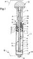
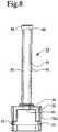
fig. 1 is a longitudinal section through a device for producing a hardenable mass during a mixing step;fig. 2 is an enlarged sectional view of a part of the device offig. 1 and shows a mixing means interconnected with a discharge means;fig. 3 is a section through the device offig. 1 during a discharge step;fig. 4 is a perspective view of a bracket forming part of the device offig. 1 ;fig. 5 is a perspective view of a discharge piston forming part of the device offig. 1 ;fig. 6 is a perspective view of a rotary-movement preventing member forming part of the device offig. 1 ;fig. 7 is a perspective view of a rotatable means forming part of the device offig. 1 ;fig. 8 is a side view of a screw mechanism according to the present invention for use at the device offig. 1 ;fig. 9 illustrates a part of the device offig. 1 containing a powder component and during injection of a liquid component;fig. 10 illustrates a part of the device offig. 1 connected to a distributor device;fig. 11 is a perspective view of the distributor device offig. 10 ; andfig. 12 illustrates the device offig. 1 during use in connection with vertebroplasty.- The
device 1 illustrated in the drawings is adapted for producing ahardenable mass 2 such as bone substitute and/or bone reinforcing material or bone cement or similar material. Thismass 2 shall be fed and/or sucked out of thedevice 1 and comprises a mixingcontainer 3 of e.g. cylindrical shape. The mixingcontainer 3 defines a mixingspace 4 in which at least onepowder component 5 and at least oneliquid component 6 are mixed to produce thehardenable mass 2. - In the mixing
space 4 there is provided a piston means 7 which is adapted to be retained relative to the mixingcontainer 3 during a mixing step and thereafter released such that it can move in the mixingspace 4 relative to the mixingcontainer 3. In order to release the piston means 7 there is provided a rotatable means 8 which in a retaining position P1 retains the piston means 7 relative to the mixingcontainer 3 and which by rotation from the retaining position P1 to a release position P2 can be released relative to the mixingcontainer 3, whereby the piston means 7 can move in the mixingspace 4. The piston means 7 and the rotatable means 8 are preferably directly or indirectly interconnected. - The
device 1 preferably but not necessarily comprises a mixing means 9 which is provided for mixing the powder andliquid components hardenable mass 2 has been produced. Then, themass 2 can be stirred with the mixing means 9 if this is appropriate or necessary. The mixing means 9 may comprise anelongated member 10, e.g. a hollow or solid rod, which extends into the mixingspace 4 and which at an inner end within the mixingspace 4 has amixing disc 11 withaxial holes 12 passing through said disc. At an outer end outside the mixingspace 4, theelongated member 10 is provided with anoperating handle 13 for operating the mixing means 9. - The mixing/stirring can be carried through in a known manner by moving the mixing means 9 back and forth in the mixing
space 4 and preferably also rotating it relative to said mixingspace 4. - The piston means 7 preferably has an
axial hole 14 extending therethrough and by means of which theelongated member 10 of the mixing means 9 extends into the mixingspace 4. Theelongated member 10 cooperates with the piston means 7 through one ormore sealing rings 15 or similar, such that a sealing is provided between said members. Theelongated member 10 and thehole 14 of the piston means 7 are adapted to each other such that saidelongated member 10 can be moved and rotated relative to the piston means 7. - At least one outer sealing 16 or similar is provided on the piston means 7 for cooperation with the inner side of the mixing
container 3 such that a sealing is defined between the piston means 7 and said inner side. Theouter sealing ring 16 is preferably designed such that it removesmass 2 which deposits on the inner side of the mixingcontainer 3 when it moves in the mixingspace 4. - The piston means 7 may also have an opening 17 with at least one
filter 18. The opening 17 is adapted to let out gases from the mixingspace 4 and thefilter 18 is adapted to prevent thecomponents 5 and/or 6 and themixed mass 2 from forcing its way out of the mixingspace 4 through the opening 17. - A rotary-
movement preventing member 19 is provided on the piston means 7. Thismember 19 is annular and includes two axially providedhook portions grooves shoulders movement preventing member 19 is attached to the piston means 7 and can not rotate relative to said means. - The rotary-
movement preventing member 19 further includes an axially providedflange 24 which is adapted to cooperate with abracket 25 in order to prevent rotation of the rotary--movement preventing member 19 and thus, the piston means 7, relative to thebracket 25 such that the mixing means 9 is rotated relative to the piston means 7 for mixing of the powder andliquid components bracket 25 has acylindrical member 27 with ahole 28 into which the rotatable means 8 can be inserted and through which said rotatable means can move when it is set in a release position P2. Thecylindrical member 27 of thebracket 25 may have an annular snap-inportion 29 which can be threaded into one ormore locking portions 30 which are located at the inner side of the mixingcontainer 3 and which allow thebracket 25 to be attached to the mixingcontainer 3 by a snap-in closure. Alternatively or in combination with said snap-inportion 29, thebracket 25 may have a number of radially projectingmembers flange 35 on the mixingcontainer 3 by a snap-in closure such that thebracket 25 can not rotate relative to said container. - The rotatable means 8 has a through
hole 8a through which theelongated member 10 of the mixing means 9 extends such that saidelongated member 10 is movable relative to the rotatable means 8 and vice versa. - The rotatable means 8 has a
first flange 36 or a corresponding member which in relation to the direction U extends radially outwards from the rotatable means 8 towards adischarge opening 49 through which themass 2 shall pass out of the mixingcontainer 3. Saidfirst flange 36 surrounds a part of the periphery of the rotatable means 8. - The
hole 28 of thebracket 25 has asecond flange 31a or a corresponding second member which relative to the direction U is directed radially into thehole 28. Thissecond flange 31a extends along a part of the periphery of thehole 28. Asection 31b or a corresponding third part of thehole 28 lacks saidflange 31a and is designed such that thefirst flange 36 of the rotatable means 8 can pass therethrough, whereby the entire rotatable means 8 can be brought to pass through thehole 28 when thefirst flange 36 and thesection 31b cooperate. - When the rotatable means 8 is set in the retaining position P1 (
fig. 1 ), then the first andsecond flanges bracket 25 in direction U, while the mixing means 9 can move and be brought to perform mixing movements for mixing the powder and liquid components in the mixingspace 4. - The rotatable means 8 can be brought to its release position P2 (
fig. 2 ) by rotating it 180° relative to thebracket 25 from its retaining position P1 and this rotary movement can be limited by bringing thefirst flange 36 thereof to engage or abut arotary stop 32. Thereby, thefirst flange 36 of the rotary means 8 will be disengaged from the cooperation with thesecond flange 31a of thebracket 25 and it can instead cooperate with thesection 31b of thebracket 25 such that the rotatable means 8 and thus, the piston means 7, can move and be displaced in direction U in relation thereto and thus, relative to the mixingcontainer 3. - The piston means 7 is prevented from rotating relative to the
bracket 25 by theflange 24 of the rotary-movement preventing member 19 engaging or gripping preferably into thesection 31b of thebracket 25 when the rotatable means 8 retains the piston means 7 at thebracket 25. - The rotatable means 8 cooperates preferably with a
coupling device 37 which is provided to interconnect the piston means 7 and theelongated member 10 of the mixing means 9 such that the piston means 7 (and the rotatable means 8 provided thereby) can be displaced in axial direction U relative to the mixingcontainer 3 by means of the mixing means 9 for discharge ofmixed mass 2 from the mixingspace 4. Thecoupling device 37 is located between the rotatable means 8 and the piston means 7 and it is preferably provided to be operated by the rotatable means 8 such that it connects the piston means 7 to theelongated member 10 while simultaneously the rotatable means 8 is rotated from its retaining position P1 to its release position P2. To this end, thecoupling device 37 may comprise a coupling means 38, e.g. a washer, which is threaded onto theelongated member 10 and which is located between the piston means 7 and the rotatable means 8. The piston means 7 has asupport member 39 which is axially directed towards the rotatable means 8 and located on one side of theelongated member 10, while there is a free space 40 on the other side of theelongated member 10. The rotatable means 8 has an axially directed bore 41, the rear parts of which are provided with ahelical spring 42 or a similar resilient element and the fore parts with a pin 43 which projects out of thebore 41. - When the rotatable means 8 is set in its retaining position P1, the
bore 41 with thehelical spring 42 is located on the same side of theelongated member 10 and the helical spring thereby presses the coupling means 38 against thesupport member 39 such that said coupling means 38 is held in a neutral position P3 in which it is held against thesupport member 39 and permits displacement of theelongated member 10 of the mixing means 9 in opposite axial mixing directions B, whereby the powder andliquid components space 4 with the mixing means 9 while the piston means 7 is retained relative to the mixingcontainer 3. - When the rotatable means 8 is rotated 180° to its release position P2, the
bore 41 and thehelical spring 42 will also move 180° relative to thesupport member 39 and thehelical spring 42 will thereby press or push the coupling means 38 into the space 40, which means that the coupling means 38 is tilted relative to theelongated member 10 and is brought to a coupling position P4 in which the coupling means 38 is fastened to theelongated member 10. Hereby, the piston means 7 is connected to the mixing means 9 such that the piston means 7 can be displaced in the direction U by said mixing means 9. - Preferably, the
coupling device 37 is designed such that it, after said interconnection of the mixing means 9 and the piston means 7, permits release of the mixing means 9 relative to the piston means 7 if said mixing means 9 is pulled in the return direction R relative to the piston means 7. - On the
operating handle 13 and/or on theelongated member 10 there may be provided anouter member 45 with anopen end portion 45a and such a cavity ordepression 45b within theend portion 45a that said end portion will engage or abut the mixingcontainer 3 when the mixing means 9 is displaced in axial direction towards the mixingcontainer 3 and rotated relative to said container during mixing. Hereby, it is prevented that said rotation of the mixing means 9 is transferred to the rotatable means 8. - The
bracket 25 is preferably provided to prevent the piston means 7 and the mixing means 9 from being pulled apart from the mixingcontainer 3. - Since the rotatable means 8 can move together with the piston means 7 in the mixing
space 4 of the mixingcontainer 3, it is ensured that thedevice 1 will be simple and that it provides for a simple and quick handling when mixing of the powder andliquid components mixed mass 2 shall be discharged. To this end, it is only necessary to rotate the rotatable means 8 from its retaining position P1 to the release position P2, whereafter it is possible to displace the piston means 7 by means of the mixing means 9 in the direction U for discharge of themass 2 from the mixingspace 4. - As an alternative to the opening 17, at least one
opening 47 can be provided in the side of the mixingcontainer 3 adjacent the piston means 7 when said piston means is retained by thebracket 25. Since theopening 47 is located adjacent the piston means 7, it is closed when the piston means 7 starts to move in the direction U and after further movement of the piston means 7, it will be located behind said piston means, which means that only gas and nomass 2 can be pressed out through theopening 47. - As an alternative to said openings, there may be at least one
opening 48 in the side of the mixingcontainer 3 about half the way between the piston means 7, when retained by thebracket 25, and adischarge opening 49 which is provided in the mixingcontainer 3 for discharge of themass 2 from said container. Theopening 48 may be closable when necessary. - The abovementioned opening 17 or
openings space 4 when e.g. theliquid component 6 is injected into said space. Since gas hereby can be pressed out, injection of theliquid component 6 is facilitated. Due to its location, the opening 48 permits gas which is entrapped in themass 2 to be pressed out of or escape from said mass during discharge thereof. - At least one vacuum generating device can be provided to generate a vacuum in the mixing
space 4 for various purposes, preferably for facilitating quick suction of theliquid component 6 to and distribution thereof in thepowder component 5 and/or e.g. for sucking out toxic gases therefrom, which are generated during mixing of the powder andliquid components container 3, but said container must be sealed. - In order to generate a vacuum in the mixing
space 4 for e.g. sucking out toxic gases, there may be a firstvacuum generating device 50 which at a suitable location can be connected to the mixingcontainer 3. Such a firstvacuum generating device 50 is schematically illustrated infig. 1 . - For discharge, the mixing means 9 can be subjected to linear forces such that said mixing means 9 and the piston means 7 are displaced linearly relative to the mixing
container 3. Alternatively, the mixing means 9 can be displaced linearly by influence from ascrew device 51 according to the present invention. - The
screw device 51 e.g. includes a nut-like member 52 which has a laterally open fork--likemember 52a with laterallyopen grooves 53 permitting sideways threading of the nut--likemember 52 onto theflange 35 of the mixingcontainer 3 such that saidmember 52 is stuck on the mixingcontainer 3. - The nut-
like member 52 is provided with a tappedhole 54 for a screw-like member 55 withouter threads 56 which mesh with the threads in the tappedhole 54 of the nut-like member 52. The screw-like member 55 may be a pipe member with amulti-side nut 58 and the pipe member may have alongitudinal slit 57 which is open in a lateral direction and the nut may have anopen side 60 such that the screw-like member 55 and thenut 58 can be threaded onto theelongated member 10 of the mixing means 9. Thenut 58 is adapted to fit into a correspondingmulti-side hole 59 in theouter member 45 or any other member on or of theoperating handle 13. - Due to the abovementioned embodiment of the
screw device 51, said device can be non--rotatably located on the mixingcontainer 3 and since thenut 58 can be inserted into thehole 59, the screw-like member 55 may, by means of theoperating handle 13, be screwed into the nut-like member 52 via e.g. theouter member 45, whereby theend portion 61 of the screw-like member 55 is brought in contact with the rotatable means 8 and can impart discharge forces in the direction U to the rotatable means 8 and through said rotatable means to the piston means 7. - The piston means 7 can be moved in the direction U either by manually pressing the operating handle 13 or rotating it and transfer the rotary movement by means of the
screw device 51. If great forces are required for discharging themass 2 from the mixingspace 4, one can use a gun-like discharge device 62 or a similar device as is schematically indicated infig. 1 . The mixingcontainer 3 is positioned therein such that a pressure means 63 can cooperate with the mixing means 9 or directly with the piston means 7 if there is no mixing means. The pressure means 63 is operated by a manually depressable trigger which can move the pressure means 63 stepwise such that said pressure means with force press the mixing means 9 and/or the piston means 7 forward in the direction U. - As is apparent from
fig. 9 , the mixingspace 4 of the mixingcontainer 3 may carry thepowder component 5 when thedevice 1 is delivered. Thedischarge opening 49 is hereby closed by aclosing device 64 which prevents thepowder component 5 from falling out of the mixingspace 4. - The
liquid component 6 can be provided in aliquid container 65 and can be fed into the mixingspace 4 for mixing therein with thepowder component 5. - The
liquid container 65 has adischarge end 66 and theclosing device 64 can be designed such that thedischarge end 66 can open theclosing device 64 when it is inserted into said device for injecting theliquid component 6 into the mixingspace 4 and thepowder component 5 therein. To this end, the closingdevice 64 may comprise avalve body 64a which is normally closed and which is opened by thedischarge end 66 when said end is inserted into theclosing device 64 and automatically returned to closed position when thedischarge end 66 is removed or withdrawn from the closingdevice 64. - A
valve 67 can be provided to cooperate with the closingdevice 64 to permit gas to escape from the mixingspace 4 when theliquid component 6 is injected into said space from theliquid container 65. Thisvalve 67 can be closed and may be opened when required. - In order to vibrate the content of the mixing
space 4, i.e. the powder andliquid components mass 2, the mixingcontainer 3 or parts thereof may be brought in contact with a vibratingdevice 68 schematically illustrated infig. 9 . - As is apparent from
fig. 10 , the mixingcontainer 3 can be connected to adistributor device 69 or vice versa.Several containers 70 can be connected thereto or vice versa, such thatmass 2 mixed in the mixingspace 4 can be fed out or discharged from said mixing space and into thedistributor device 69. Thedistributor device 69 distributes themass 2 to thevarious containers 70 such that portions of themass 2 are fed intoinner spaces 71 in thecontainers 70. Theinner space 71 in eachcontainer 70 is substantially smaller than the mixingspace 4 of the mixingcontainer 3, which means that one can fill thespaces 71 of a plurality ofcontainers 70, e.g. thespaces 71 of eightcontainers 70, with apart volume 2a of themass 2 from the mixingspace 4. - When the
spaces 71 of the respective number ofcontainers 70 are filled with saidpart volume 2a of themass 2, eachcontainer 70 can be removed from thedistributor device 69 or vice versa and thepart volume 2a ofmass 2 in thecontainer 70 can be fed and/or sucked out of thecontainer 70. - The
distributor device 69 preferably comprises adistributor body 72 with anaxial inlet pipe 73 which can be located close to such an outlet or dischargeend 74 of the mixingcontainer 3 having thedischarge opening 49. Theinlet pipe 73 can be located at thedischarge end 74 by screwing on or in any other suitable manner such that inner passages in thedistributor body 72 communicate with thedischarge opening 49. Of course, the mixing container may instead be located on theinlet pipe 73. - The
distributor device 69 may also comprise a number of discharge pipes 75-82, at least two and e.g. eight pipes, which extend radially in a star-like manner from thedistributor body 72 and which communicate with inner members of thedistributor body 72. - Each
container 70 has afront part 84 through which it can be mounted, e.g. screwed on to one of the discharge pipes 75-82 of thedistributor device 69 or vice versa, such that apart volume 2a ofmass 2 can be fed into thespace 71. During this filling of thespace 71, apiston 86 forming part of thecontainer 70 is preferably located in arear part 85 of thecontainer 70. After thespace 71 has been filled with thepart volume 2a ofmass 2, a cannula orneedle 83 can be located on thefront part 84. Thepart volume 2a ofmass 2 is fed or sucked out of thespace 71 of thecontainer 70 through saidcannula 83. - Each
container 70 may eventually have anopening 87 which preferably is found in therear part 85 and immediately in front of thepiston 86 when said piston is situated in therear part 85. Thisopening 87 allows gas in thespace 71 of thecontainer 70 to be pressed out of the space when saidpart volume 2a ofmass 2 is fed into saidspace 71. Hereby, it is prevented that gas in thespace 71 resists entrance of thepart volume 2a ofmass 2 into saidspace 71. Theopening 87 has e.g. a diameter of 0,2-1,0 mm, preferably about 0,6 mm. - The
opening 87 may alternatively be a groove (not shown) provided axially in the inner side of thecontainer 70 and extending beyond thepiston 86 when said piston is situated in therear part 85 of thecontainer 70. - When the required number of
containers 70 have been filled with thepart volume 2a ofmass 2, onecontainer 70 at the time is removed from thedistributor device 69 and a cannula orneedle 83 is mounted preferably on thefront part 84 of thecontainer 70 such that thepart volume 2a ofmass 2 can be fed or sucked out through thecannula 83 with or without support from thepiston 86 until thespace 71 is empty. By removing onecontainer 70 at the time from thedistributor device 69 and letting the other filledcontainers 70 remain mounted thereon, it is achieved that themass 2 in thecontainers 70 not yet removed is not subjected to atmospheric air for an unnecessarily long time. - Since the size of the
space 71 in eachcontainer 70 is known, one knows exactly how large apart volume 2a ofmass 2 which is fed out of or discharged from eachcontainer 70. - For treating
spongy bone 89 withmass 2, saidmass 2 can be sucked intoinner parts 89a of thespongy bone 89. To this end, acontainer 70 is connected to thespongy bone 89 by inserting thecannula 83 thereof, or a member (not shown) to which thecannula 83 can be connected, into theinner parts 89a such that thespace 71 of thecontainer 70 communicates therewith. To saidinner parts 89a of thespongy bone 89 there is also connected at least onevacuum source 90 through aconnection line 92 for generating a vacuum in theinner parts 89a and in thespace 71 of thecontainer 70 connected thereto such that thepart volume 2a ofmass 2 is sucked out of saidspace 71 and through thecannula 83 into theinner parts 89a of thespongy bone 89. During this suction step, thepiston 86 may eventually be displaced in the direction U for supporting the suction of thepart volume 2a of themass 2 out of thespace 71. Inner parts 89a of thespongy bone 89 can be provided withmass 2 from the mixingcontainer 3. The mixingcontainer 3 can be provided with a cannula or needle (not shown) or similar and this cannula is inserted into theinner parts 89a. Themass 2 can thereby be sucked out of the mixingspace 4 of the mixingcontainer 3 and into theinner parts 89a by means of thevacuum source 90. Eventually, this suction ofmass 2 from the mixingspace 4 may be supported by a displacement of the piston means 7 in the direction U.- The
spongy bone 89 may e.g. be a spongy vertebra or an osteoporosis fracture in the form of a thighbone (femoral) or knee (patellar) fracture. Mixed mass 2 in the mixingcontainer 3 can be used for fixation of implants, whereby one can provide the container with a discharge pipe or similar (not shown), through which themass 2 is discharged by means of the piston means 7 into cavities in the bone in which the implant shall be fixed.- The
mass 2 may consist of bone substitute and/or bone reinforcing material which primarily consist of calcium base material or ceramics which can be mixed with a hardener, e.g. water. These substances may be selected from the group comprising calcium sulphate-a-hemihydrate, calcium sulphate-β-hemihydrate, calcium sulphate-dihydrate, calcium carbonate, α-tricalcium phosphate, hydroxyapatite, dicalcium phosphate-dihydrate, anhydrous dicalcium phosphate, tetracalcium phosphate, β-tricalcium phosphate, calcium deficient hydroxyapatite, monocalcium phosphate-monohydrate, monocalcium phosphate, calcium-pyurophosphate, precipitated hydroxyapatite, carbonaceous apatite (dahlite), octacalcium phosphate, amorphous calcium phosphate, oxyapatite, carbonato apatite and calcium aluminate. - A ceramic material may be calcium aluminate, which forms part of the product Doxa T from the company Doxa (www.doxa.se/pdf/nyhet_1.pdt).
- X-ray contrast agents can be added to said ceramic bone substitute and/or bone reinforcing material, e.g. water soluble non-ionic X-ray contrast agents selected from the group comprising iohexol, ioversol, iopamidol, iotrolan, metrizamide, iodecimol, ioglucol, ioglucamide, ioglunide, iogulamide, iomeprol, iopentol, iopromide, iosarcol, iosimide, iotusal, ioxi-Ian, iofrotal and iodecol.
- Alternatively, the
mass 2 can be a hardenable bone cement comprising polymer and monomer components. The polymer may be polymethylmethacrylate (PMMA) and the monomer methylmethacrylate (MMA). A polymer base material can be the product Cortoss™ from the company Orthovita in the U.S.A.. For composition see www.orthovita.com/products/cortoss/oustechspecs.html. Another polymer base material can be the product SECOUR® Acrylic Resin PMMA from parallax medical inc. (www.parallax-medical.com/go/ 91-92b550-5642-1157-a432-d7a2b98310fe). - The
mass 2 can be a bone substitute and/or bone reinforcing material and consist of a mineral and/or a ceramic in combination with polymer material. - The
screw device 51 may be a device which can be connected to a mixingcontainer 3 which is designed in another way than what is illustrated in the drawings and where the piston means 7 is located and operated in another way than what is shown in the drawings. - The
distributor device 69 can be connected to a mixingcontainer 3 or vice versa which is designed in another way than what is shown in the drawings and where the piston means 7 is mounted in another way than what is shown in the drawings. - The invention is not limited to the embodiments described above and illustrated in the drawings. As examples not described in detail, it should be mentioned that the
mass 2 may be another type of mass than bone substitute and/or bone reinforcing material or bone cement or similar. The rotatable means 8 may cooperate with the piston means with other means than those shown and described; mixing may be carried through in another way than with a mixing means 9 and if there is such a means, this may be designed otherwise; the mixingcontainer 3 may be designed in another way than what is described and illustrated; when using adistributor device 69, this may be of another type than the one described and illustrated. The piston means 7 may either be moved in the direction U by the mixing means 9 or be sucked in the same direction by thevacuum source 90, but it is also possible to move the piston means 7 by using the mixing means 9 and thevacuum source 90 simultaneously. Thedevice 1 may be of the disposable type or used repeatedly.
Claims (2)
- A system for producing a hardenable mass (2), preferably bone substitute and/or bone reinforcing material or bone cement or similar material, the system comprising a device for producing the hardenable mass and a screw device (51); wherein the device for producing the hardenable mass includes a mixing means (9) and a mixing container (3), said mixing container (3) having a mixing space (4) in which at least one powder and at least one liquid component (5, 6) are mixed to produce the hardenable mass (2) and in which a piston means (7) is provided to discharge the hardenable mass from said mixing space, wherein the screw device (51) is adapted to be connected to the mixing container (3), wherein the screw device (51) includes a nut-like member (52) and a screw-like member (55) which is adapted to be screwed into the nut-like member (52) and wherein the screw-like member is adapted to be located on an operating handle (13) or similar forming part of a mixing means (9) such that the screw-like member (55) can move the piston means (7) in a direction (U) by screwing said screw-like member (55) into the nut-like member (52) by means of the operating handle (13), thereby discharging the hardenable mass (2) from the mixing space;characterized in that the nut-like member (52) is adapted to be located on the mixing container (3) such that said screw device (51) is non-rotatable relative to the mixing container (3) and that the screw-like member is adapted to be located on an operating handle (13) or similar forming part of a mixing means (9) such that the operating handle (13) and the screw-like member (55) are nonrotatably connected to each other.
- System according to claim 1,characterized in that the screw-like member (55) is a pipe member with a multi-side nut (58) and the pipe member has a longitudinal slit (57) which is open in a lateral direction and the nut (58) has an open side (60) such that the pipe member (55) and the nut (58) can be threaded onto an elongated member (10) of the mixing means (9).
Applications Claiming Priority (3)
| Application Number | Priority Date | Filing Date | Title |
|---|---|---|---|
| SE0401604ASE527528C2 (en) | 2004-06-22 | 2004-06-22 | Apparatus for the preparation of curable pulp and use of the apparatus |
| EP05752716AEP1758526B1 (en) | 2004-06-22 | 2005-06-17 | Device for producing a hardenable mass |
| PCT/SE2005/000932WO2005122971A1 (en) | 2004-06-22 | 2005-06-17 | Device for producing a hardenable mass |
Related Parent Applications (1)
| Application Number | Title | Priority Date | Filing Date |
|---|---|---|---|
| EP05752716ADivisionEP1758526B1 (en) | 2004-06-22 | 2005-06-17 | Device for producing a hardenable mass |
Publications (2)
| Publication Number | Publication Date |
|---|---|
| EP2108324A1 EP2108324A1 (en) | 2009-10-14 |
| EP2108324B1true EP2108324B1 (en) | 2019-01-16 |
Family
ID=32906836
Family Applications (4)
| Application Number | Title | Priority Date | Filing Date |
|---|---|---|---|
| EP08151034AExpired - LifetimeEP1920738B1 (en) | 2004-06-22 | 2005-06-17 | Device for distributing a hardenable mass |
| EP05752716AExpired - LifetimeEP1758526B1 (en) | 2004-06-22 | 2005-06-17 | Device for producing a hardenable mass |
| EP09158716.2AExpired - LifetimeEP2108324B1 (en) | 2004-06-22 | 2005-06-17 | Device for producing a hardenable mass |
| EP08151033AExpired - LifetimeEP1913888B1 (en) | 2004-06-22 | 2005-06-17 | Device for producing a hardenable mass. |
Family Applications Before (2)
| Application Number | Title | Priority Date | Filing Date |
|---|---|---|---|
| EP08151034AExpired - LifetimeEP1920738B1 (en) | 2004-06-22 | 2005-06-17 | Device for distributing a hardenable mass |
| EP05752716AExpired - LifetimeEP1758526B1 (en) | 2004-06-22 | 2005-06-17 | Device for producing a hardenable mass |
Family Applications After (1)
| Application Number | Title | Priority Date | Filing Date |
|---|---|---|---|
| EP08151033AExpired - LifetimeEP1913888B1 (en) | 2004-06-22 | 2005-06-17 | Device for producing a hardenable mass. |
Country Status (15)
| Country | Link |
|---|---|
| US (4) | US7938572B2 (en) |
| EP (4) | EP1920738B1 (en) |
| JP (1) | JP4891900B2 (en) |
| KR (1) | KR101247172B1 (en) |
| CN (2) | CN1972648B (en) |
| AT (3) | ATE463217T1 (en) |
| AU (1) | AU2005253916B2 (en) |
| CA (2) | CA2800025C (en) |
| DE (3) | DE602005020524D1 (en) |
| ES (3) | ES2341504T3 (en) |
| PL (3) | PL1920738T3 (en) |
| PT (1) | PT1913888E (en) |
| SE (1) | SE527528C2 (en) |
| WO (1) | WO2005122971A1 (en) |
| ZA (1) | ZA200610100B (en) |
Families Citing this family (66)
| Publication number | Priority date | Publication date | Assignee | Title |
|---|---|---|---|---|
| SE520688C2 (en)* | 2000-04-11 | 2003-08-12 | Bone Support Ab | An injectable bone mineral replacement material |
| SE517168C2 (en)* | 2000-07-17 | 2002-04-23 | Bone Support Ab | A composition for an injectable bone mineral replacement material |
| SE522098C2 (en) | 2001-12-20 | 2004-01-13 | Bone Support Ab | Artificial bone mineral substitute material useful as an X-ray contrast medium comprises ceramic and water soluble non-ionic X-ray contrast agent |
| SE0300620D0 (en) | 2003-03-05 | 2003-03-05 | Bone Support Ab | A new bone substitute composition |
| SE0302983D0 (en)* | 2003-11-11 | 2003-11-11 | Bone Support Ab | Apparatus for providing spongy bone with bone replacement and / or bone strengthening material and associated method |
| ES2286713T3 (en)* | 2003-12-01 | 2007-12-01 | Broockeville Corporation N.V. | MIXING AND DISPENSING DEVICE OF TWO COMPONENTS. |
| SE527528C2 (en) | 2004-06-22 | 2006-04-04 | Bone Support Ab | Apparatus for the preparation of curable pulp and use of the apparatus |
| US8057090B1 (en)* | 2005-08-31 | 2011-11-15 | Subrata Saha | Automated bone cement mixer |
| JP2009525868A (en)* | 2006-02-10 | 2009-07-16 | ダウ グローバル テクノロジーズ インコーポレイティド | Retractable pin mixed sample forming device |
| DE102007026034B4 (en)* | 2007-06-04 | 2016-03-03 | Aap Biomaterials Gmbh | Method for mixing mix with a mixing and application device |
| ITPD20070266A1 (en)* | 2007-08-02 | 2009-02-03 | Michela Facco | DISTRIBUTION DEVICE APPLICABLE TO MANUAL DOSERS FOR VERTEBROPLASTICS |
| DE102007061696B4 (en) | 2007-12-19 | 2010-03-18 | Heraeus Medical Gmbh | Mixing device, especially for bone cements |
| AU2009296318B2 (en)* | 2008-09-29 | 2014-09-18 | Lidds Ab | Injector device |
| US8162875B2 (en)* | 2008-09-30 | 2012-04-24 | Tyco Healthcare Group Ip | Diluent/medication mixing syringe assembly |
| PL2393455T3 (en) | 2009-02-06 | 2019-02-28 | Tecres S.P.A. | Supply unit for a mixer of two-phase compounds |
| DE102009013211B4 (en) | 2009-03-17 | 2012-04-19 | Aap Biomaterials Gmbh | Bone cement vacuum mixing device and method for mixing bone cement |
| CH700895A1 (en) | 2009-04-28 | 2010-10-29 | Medmix Systems Ag | Discharge WITH MIXING DEVICE. |
| DE102009031178B3 (en)* | 2009-06-29 | 2010-09-16 | Heraeus Medical Gmbh | Device for mixing and delivering bone cement |
| EP2353619A1 (en) | 2010-02-09 | 2011-08-10 | Bone Support AB | Preparation of Bone Cement Compositions |
| US9180137B2 (en) | 2010-02-09 | 2015-11-10 | Bone Support Ab | Preparation of bone cement compositions |
| DE102010052323A1 (en)* | 2010-11-25 | 2012-05-31 | Heraeus Medical Gmbh | Cartridge with lockable delivery piston |
| DE102011005568A1 (en)* | 2011-03-15 | 2012-09-20 | Krones Aktiengesellschaft | Plant and process for recycling plastics, preferably PET |
| CH705193A1 (en)* | 2011-06-22 | 2012-12-31 | Medmix Systems Ag | Apparatus for bubble poor mixing and dispensing a product. |
| DE102011112516B4 (en) | 2011-09-07 | 2024-02-29 | Stryker European Operations Holdings Llc | Container with a container for holding a liquid and a liquid removal device |
| DE102011119377B3 (en)* | 2011-11-25 | 2013-04-04 | Heraeus Medical Gmbh | Storage and mixing device for bone cement |
| DE102011119371B3 (en) | 2011-11-25 | 2013-04-04 | Heraeus Medical Gmbh | Device for mixing bone cement |
| US9630355B2 (en)* | 2011-11-30 | 2017-04-25 | King Abdulaziz City For Science And Technology | Batch mixer with plunger |
| US8833606B2 (en)* | 2012-01-03 | 2014-09-16 | Howmedica Osteonics Corporation | Device and method for mixing and applying biomaterials |
| WO2013131520A2 (en) | 2012-03-06 | 2013-09-12 | Ferrosan Medical Devices A/S | Pressurized container containing haemostatic paste |
| CN104349797B (en) | 2012-06-12 | 2017-10-27 | 弗罗桑医疗设备公司 | Dry hemostatic composition |
| KR101275638B1 (en)* | 2012-10-31 | 2013-06-17 | (주)비엠코리아 | Mixing and injection tool of bone cement |
| DE102012021623B4 (en) | 2012-11-06 | 2021-03-04 | Otto-Von-Guericke-Universität Magdeburg | Device and method for calibrating tracking systems in imaging systems |
| DE102012024710A1 (en)* | 2012-11-07 | 2014-05-08 | Heraeus Medical Gmbh | Device for mixing and discharging a pasty mass |
| JP6352947B2 (en) | 2013-02-20 | 2018-07-04 | ボーナ スーポート アーベー | Improved hardening of sclerosing bone substitutes |
| US9604184B2 (en) | 2013-03-06 | 2017-03-28 | Orthovita, Inc. | Mixing system and valve assembly |
| US20160008507A1 (en)* | 2013-03-13 | 2016-01-14 | National Institute For Materials Science | Adhesive bone filling agent and adhesive bone filling agent kit |
| DE102013011295A1 (en) | 2013-07-08 | 2015-01-08 | Heraeus Medical Gmbh | Device for storing and mixing bone cement |
| DE202013010100U1 (en) | 2013-11-07 | 2015-02-09 | Mathys Ag Bettlach | Dosing device for filling Appliziervorrichtungen with bone cement or bone replacement pastes |
| RU2678592C1 (en) | 2013-12-11 | 2019-01-30 | Ферросан Медикал Дивайсиз А/С | Dry composition comprising extrusion enhancer |
| TWI651103B (en) | 2013-12-13 | 2019-02-21 | 萊特醫技股份有限公司 | Multiphase bone graft replacement material |
| DE102013226118B3 (en)* | 2013-12-16 | 2015-06-11 | Heraeus Medical Gmbh | Device for storing and mixing bone cement |
| JP6726852B2 (en) | 2014-10-13 | 2020-07-22 | フェッローサン メディカル ディバイス エー/エス | Dry composition for use in hemostasis and wound healing |
| DE202014008486U1 (en) | 2014-10-27 | 2016-01-28 | Mathys Ag Bettlach | Device for applying bone replacement pastes |
| AU2016236326A1 (en) | 2015-03-23 | 2017-10-12 | Bone Support Ab | Biphasic ceramic bone substitute |
| DE102015108783B3 (en)* | 2015-06-03 | 2016-07-14 | Heraeus Medical Gmbh | Device for mixing and storing polymethyl methacrylate bone cement |
| US10507293B2 (en) | 2015-06-24 | 2019-12-17 | Ethicon, Inc. | Hemostatic powder delivery devices and methods |
| EP3316930B1 (en)* | 2015-07-03 | 2019-07-31 | Ferrosan Medical Devices A/S | Syringe for mixing two components and for retaining a vacuum in a storage condition |
| DE102015116797B4 (en) | 2015-10-02 | 2018-08-23 | Heraeus Medical Gmbh | Apparatus and method for storing and mixing a bone cement |
| DE102016110561A1 (en) | 2016-06-08 | 2017-12-14 | Heraeus Medical Gmbh | Storage and mixing device for producing a bone cement |
| US9956143B2 (en)* | 2016-06-14 | 2018-05-01 | Pharmac, Llc | Syringe apparatus for transferring liquids into and out of a vial having a septum |
| US10905485B2 (en)* | 2016-07-27 | 2021-02-02 | Zimmer Biomet France Sas | Apparatus for mixing bone cement |
| US9869729B1 (en)* | 2016-08-30 | 2018-01-16 | Infineon Technologies Ag | Magnetic field sensor circuit in package with means to add a signal from a coil |
| DE102016121607B4 (en)* | 2016-11-11 | 2019-05-16 | Heraeus Medical Gmbh | Apparatus and method for storing and mixing a bone cement |
| DE102017109255A1 (en)* | 2017-04-28 | 2018-10-31 | Heraeus Medical Gmbh | Bone cement application device with closure means on the discharge piston |
| WO2019023805A1 (en) | 2017-08-04 | 2019-02-07 | Mark Robert Towler | A storage, mixing and dispensing device |
| DE102017130084B4 (en)* | 2017-12-15 | 2019-06-27 | Heraeus Medical Gmbh | Bone cement mixing device with spacer in a vial holder |
| DE102018101041A1 (en)* | 2018-01-18 | 2019-07-18 | Heraeus Medical Gmbh | Bone cement applicator with sealable gassing opening |
| US11229467B2 (en) | 2018-04-11 | 2022-01-25 | Zimmer Gmbh | Valve for prefilled bone cement mixing system |
| DE102018131266B4 (en)* | 2018-12-07 | 2021-12-23 | Heraeus Medical Gmbh | Apparatus for mixing a bone cement with a cavity for monomer transfer and a process for the production of a bone cement dough |
| DE102019104020A1 (en)* | 2019-02-18 | 2020-08-20 | Heraeus Medical Gmbh | Bone cement applicator with clampable discharge piston |
| CN109908815B (en)* | 2019-04-26 | 2020-04-17 | 中国医学科学院阜外医院 | Cardiovascular image examination contrast agent preparation equipment |
| US11298242B2 (en) | 2019-06-14 | 2022-04-12 | Medos International Sarl | Biomaterial delivery device, and related systems and methods |
| WO2021212275A1 (en)* | 2020-04-20 | 2021-10-28 | Covidien Lp | Motorized mixing device for use with medical agents |
| SE546296C2 (en)* | 2021-10-11 | 2024-09-24 | Biomimetic Innovations Ltd | Method and system for preparing a biomaterial |
| CN114305640B (en)* | 2021-12-27 | 2022-08-19 | 西安交通大学第二附属医院 | Bone grafting device for orthopedics department |
| US12329658B2 (en)* | 2022-02-14 | 2025-06-17 | Warsaw Orthopedic, Inc. | Graft delivery device with accurate dispensing |
Family Cites Families (186)
| Publication number | Priority date | Publication date | Assignee | Title |
|---|---|---|---|---|
| US949153A (en)* | 1909-05-15 | 1910-02-15 | Wilhelm Majert | Metallic-filament incandescent lamp. |
| US949163A (en)* | 1909-07-07 | 1910-02-15 | Bridgeport Brass Co | Grease-gun. |
| US1644173A (en)* | 1923-02-01 | 1927-10-04 | Bassick Mfg Co | Lubricating apparatus |
| US1865912A (en)* | 1930-03-25 | 1932-07-05 | Horn William | Oil well agitator |
| US2129675A (en)* | 1935-06-12 | 1938-09-13 | Samuel Cole | Syringe |
| US2545017A (en)* | 1947-06-02 | 1951-03-13 | Gordon D Billingsley | Hypodermic syringe |
| US3367783A (en) | 1966-03-23 | 1968-02-06 | Gerber Prod | Process of preparing a fruit gel |
| US3470893A (en)* | 1968-03-04 | 1969-10-07 | Illinois Tool Works | Fluid distribution unit |
| US3475010A (en)* | 1968-04-24 | 1969-10-28 | Prod Res & Chem Corp | Dispensing cartridge for intermixing separate ingredients |
| US3570719A (en)* | 1968-07-02 | 1971-03-16 | Louis Schiff | Reagent mixing and dispensing apparatus |
| US3688765A (en)* | 1969-10-03 | 1972-09-05 | Jack S Gasaway | Hypodermic injection device |
| US3837379A (en) | 1973-05-14 | 1974-09-24 | East West Med Prod | Irrigator liquid supply system |
| CH608189A5 (en)* | 1974-12-13 | 1978-12-29 | Savac Ag | |
| US3965910A (en) | 1975-04-28 | 1976-06-29 | Walpak Company | Urinary irrigation valve |
| CH626873A5 (en)* | 1977-03-28 | 1981-12-15 | Bracco Ind Chimica Spa | |
| US4240425A (en)* | 1978-10-23 | 1980-12-23 | American Hospital Supply Corporation | Syringe with plug type needle hub lock |
| IT1207226B (en) | 1979-08-09 | 1989-05-17 | Bracco Ind Chimica Spa | 2,4,6-TRIIODE-ISOPHTHALIC ACID DERIVATIVES, METHOD FOR THEIR PREPARATION AND CONTRAST MEANS THAT CONTAIN THEM. |
| US4338925A (en)* | 1979-12-20 | 1982-07-13 | Jo Miller | Pressure injection of bone cement apparatus and method |
| US4269331A (en)* | 1980-02-15 | 1981-05-26 | Watson John D | Metered dispensing device |
| US4496342A (en) | 1981-03-20 | 1985-01-29 | Surgical Design Corporation | Surge prevention system for an ophthalmic instrument |
| DE3206911A1 (en)* | 1982-02-26 | 1983-09-15 | Lohmann Tierernährung GmbH, 2190 Cuxhaven | BIOCHEMICAL ACTIVE SUBSTANCE, THE PRODUCTION THEREOF AND SUBSTANCE CONTAINING THIS ACTIVE SUBSTANCE |
| US4439420A (en) | 1982-11-16 | 1984-03-27 | Ethicon, Inc. | Absorbable hemostatic composition |
| US4584401A (en) | 1983-10-20 | 1986-04-22 | Biophysica Foundation | Methods and compositions involving polyhydroxylated polyiodo non-ionic contrast media |
| US4619655A (en)* | 1984-01-26 | 1986-10-28 | University Of North Carolina | Plaster of Paris as a bioresorbable scaffold in implants for bone repair |
| US4583974A (en)* | 1984-04-04 | 1986-04-22 | Kokernak Denis T | Syringe for balloon dilation catheters |
| DK350584A (en)* | 1984-07-18 | 1986-01-19 | Arne Bent Sjoegren | MIXING PUMP FOR EFFECTIVE MIXING (HOMOGENIZATION) OF TWO OR MORE LIQUIDS (AIR SPECIES) WITH A CONSTANT, BUT REGULAR, MIXING CONDITIONS |
| JPS6199623A (en) | 1984-10-18 | 1986-05-17 | High Frequency Heattreat Co Ltd | Quenching method controlled numerically |
| SE450545B (en)* | 1984-10-19 | 1987-07-06 | Mit Ab | PROCEDURE AND DEVICE FOR MANUFACTURING BENCEMENT FOR FIXING PROSTHESIS |
| GB8516344D0 (en)* | 1985-06-28 | 1985-07-31 | Brunold C R | Mixing apparatus & processes |
| US4676655A (en) | 1985-11-18 | 1987-06-30 | Isidore Handler | Plunger type cartridge mixer for fluent materials |
| WO1987005521A1 (en) | 1986-03-11 | 1987-09-24 | University Of Medicine And Dentistry Of New Jersey | Moldable bone implant material |
| US4752479A (en)* | 1986-05-27 | 1988-06-21 | Ciba-Geigy Corporaton | Multi vitamin and mineral dietary supplement with controlled release bioavailable iron |
| JPH01501756A (en)* | 1986-11-19 | 1989-06-22 | ラボラトリウム フュー エクスペリメンテル シルージー、フォーチュングスインスティチュート、ダフォス | Method and apparatus for preparing self-hardening two-component powder-liquid bone cement |
| EP0305417B1 (en)* | 1987-02-20 | 1995-06-28 | DRAENERT, Klaus, Dr.med. | Suction drainage-bone screw |
| ES2007350A6 (en)* | 1987-05-29 | 1989-06-16 | Ganadera Union Ind Agro | FOOD PRODUCTS ENRICHED WITH NUCLEOSIDES AND NOT NUCLEOTIDES FOR THE NUTRITION OF CHILDREN AND ADULTS, AND PROCEDURE FOR THEIR PREPARATION. |
| DE3731542A1 (en)* | 1987-09-17 | 1989-03-30 | Schering Ag | NEW DICARBONIC ACID-BIS (3,5-DICARBAMOYL-2,4,6-TRIIOD-ANILIDE), METHOD FOR THE PRODUCTION THEREOF AND THESE CONTAINING X-RAY AGENTS |
| GB8724897D0 (en) | 1987-10-23 | 1987-11-25 | Downes S | Material |
| US5605885A (en) | 1988-05-05 | 1997-02-25 | Entremed, Inc. | Method for stimulating the immune system |
| WO1990005666A2 (en)* | 1988-11-14 | 1990-05-31 | Oden Corporation | Precision filling machine |
| SE462315B (en)* | 1989-05-03 | 1990-06-11 | Surgitec Ab | DEVICE FOR MANUFACTURING BENCEMENT |
| AU5950790A (en) | 1989-06-30 | 1991-01-17 | United States Gypsum Company | Calcium sulfate hemihydrate composition having utility in the presence of blood |
| GB8919929D0 (en)* | 1989-09-04 | 1989-10-18 | Nycomed As | Compositions |
| SE464912B (en) | 1989-10-25 | 1991-07-01 | Bioapatite Ab | Implantation material for re-establishing bone tissue and method for its production |
| US5236456A (en) | 1989-11-09 | 1993-08-17 | Osteotech, Inc. | Osteogenic composition and implant containing same |
| IT1236864B (en) | 1989-12-29 | 1993-04-22 | Tecres Spa | PROCEDURE FOR MIXING AND ADMINISTRATING A TWO-PART BONE CONCRETE DIRECTLY ON THE SPOT, AND DEVICE THAT REALIZES IT |
| US5071040A (en)* | 1990-03-09 | 1991-12-10 | Pfizer Hospital Products Group, Inc. | Surgical adhesives mixing and dispensing implement |
| WO1991017722A1 (en) | 1990-05-11 | 1991-11-28 | Lifecore Medical, Inc. | Rapid setting hydroxylapatite and plaster formulation |
| US5168757A (en)* | 1990-05-15 | 1992-12-08 | Ryder International Corporation | Fluid displacement and pressurizing device |
| US5269785A (en) | 1990-06-28 | 1993-12-14 | Bonutti Peter M | Apparatus and method for tissue removal |
| US5990382A (en)* | 1990-08-29 | 1999-11-23 | Biomedical Enterprises, Inc. | Method and implant for surgical manipulation of bone |
| US6080801A (en)* | 1990-09-13 | 2000-06-27 | Klaus Draenert | Multi-component material and process for its preparation |
| US5149368A (en)* | 1991-01-10 | 1992-09-22 | Liu Sung Tsuen | Resorbable bioactive calcium phosphate cement |
| US5262166A (en) | 1991-04-17 | 1993-11-16 | Lty Medical Inc | Resorbable bioactive phosphate containing cements |
| US5462722A (en)* | 1991-04-17 | 1995-10-31 | Liu; Sung-Tsuen | Calcium phosphate calcium sulfate composite implant material |
| US5232024A (en)* | 1991-05-30 | 1993-08-03 | Eli Williams | Slide-valve manifold |
| DE4121043A1 (en)* | 1991-06-26 | 1993-01-07 | Merck Patent Gmbh | BONE REPLACEMENT MATERIAL WITH FGF |
| EP0520690B1 (en) | 1991-06-26 | 1995-11-02 | Nitta Gelatin Inc. | Calcium phosphate type hardening material for repairing living hard tissue |
| JPH0690971A (en)* | 1991-12-03 | 1994-04-05 | Janome Sewing Mach Co Ltd | Production of bone implant |
| SE501676C2 (en)* | 1992-01-22 | 1995-04-10 | Pharmacia Ab | Drug dosing device |
| US5281265A (en) | 1992-02-03 | 1994-01-25 | Liu Sung Tsuen | Resorbable surgical cements |
| SE510490C2 (en)* | 1992-02-07 | 1999-05-31 | Scandimed International Ab | Process for producing bone cement and apparatus for carrying out the process |
| CA2103683C (en)* | 1992-08-17 | 1998-06-16 | George Weeks | Methods of controlling dust and compositions produced thereby |
| DE59307864D1 (en)* | 1992-09-18 | 1998-01-29 | Haindl Hans | SAFETY CONNECTOR FOR INFUSION THERAPY |
| IT1256248B (en)* | 1992-12-24 | 1995-11-29 | Bracco Spa | WATER INJECTABLE FORMULATIONS FOR RADIODIAGNOSTICS INCLUDING MIXTURES OF IODURATED AROMATIC COMPOUNDS USEFUL AS X-RAY MATTING AGENTS |
| US5403318A (en) | 1993-01-15 | 1995-04-04 | Boehringer Laboratories, Inc. | Apparatus and method for shaping bone |
| US5404922A (en)* | 1993-08-02 | 1995-04-11 | Sliter; Spencer | Apparatus and method for evenly dispensing gelatin-based solutions |
| SE510491C2 (en) | 1993-08-18 | 1999-05-31 | Coripharm Gmbh & Co | Cement for medical use and manufacture and use of the cement |
| US5665066A (en)* | 1993-09-03 | 1997-09-09 | Ultradent Products, Inc. | Methods and apparatus for mixing and dispensing multi-part compositions |
| US5328462A (en)* | 1993-09-03 | 1994-07-12 | Ultradent Products, Inc. | Methods and apparatus for mixing and dispensing multi-part compositions |
| US5681873A (en)* | 1993-10-14 | 1997-10-28 | Atrix Laboratories, Inc. | Biodegradable polymeric composition |
| US5360823A (en)* | 1993-11-02 | 1994-11-01 | Dawe's Inc. | Anionic salt formulation for milk fever |
| EP0657208A1 (en) | 1993-12-08 | 1995-06-14 | Allo Pro Ag | Device for mixing a multicomponent cement and process for performing the mixing |
| GB9325342D0 (en) | 1993-12-10 | 1994-02-16 | Dow Corning Sa | Process for polymerisation |
| US6248110B1 (en)* | 1994-01-26 | 2001-06-19 | Kyphon, Inc. | Systems and methods for treating fractured or diseased bone using expandable bodies |
| US6716216B1 (en)* | 1998-08-14 | 2004-04-06 | Kyphon Inc. | Systems and methods for treating vertebral bodies |
| GB9403362D0 (en)* | 1994-02-22 | 1994-04-13 | Summit Medical Ltd | Bone cement mixing apparatus |
| DE4409610C3 (en) | 1994-03-21 | 2001-09-20 | Scandimed Internat Ab Sjoebo | Mixing device |
| DE4425218A1 (en)* | 1994-07-16 | 1996-01-18 | Merck Patent Gmbh | Device for mixing and discharging bone cement |
| US6075067A (en)* | 1994-08-15 | 2000-06-13 | Corpipharm Gmbh & Co | Cement for medical use, method for producing the cement, and use of the cement |
| DE4433201A1 (en)* | 1994-09-17 | 1996-03-21 | Merck Patent Gmbh | Process for the production of active ingredient-containing bone cements |
| DE4435680A1 (en)* | 1994-10-06 | 1996-04-11 | Merck Patent Gmbh | Porous bone substitute materials |
| US5616120A (en) | 1995-02-06 | 1997-04-01 | Andrew; Mark S. | Method and apparatus for lenticular liquefaction and aspiration |
| US5614206A (en)* | 1995-03-07 | 1997-03-25 | Wright Medical Technology, Inc. | Controlled dissolution pellet containing calcium sulfate |
| US5674394A (en)* | 1995-03-24 | 1997-10-07 | Johnson & Johnson Medical, Inc. | Single use system for preparation of autologous plasma |
| JPH11506659A (en) | 1995-06-06 | 1999-06-15 | オステオジェニックス・インコーポレーテッド | Biocompatible hydroxyapatite formulations and uses thereof |
| DE69623597T2 (en)* | 1995-12-19 | 2003-05-22 | Bracco Research S.A., Carouge | COMPOSITIONS CONTAINING TRICODOBENZENE POLYMERS FOR IMAGING THE GASTROINTESTINAL TRACT |
| US6596904B1 (en)* | 1996-01-29 | 2003-07-22 | Mallinc Krodt Inc | Process for producing ioversol |
| US6299905B1 (en) | 1996-04-16 | 2001-10-09 | Depuy Orthopaedics, Inc. | Bioerodable polymeric adhesives for tissue repair |
| DE19620117C1 (en) | 1996-05-18 | 1997-07-24 | Corimed Kundenorientierte Medi | Preparation of medicinal composition containing calcium sulphate |
| FR2749756B1 (en)* | 1996-06-14 | 1998-09-11 | Bioland | PROCESS FOR THE PREPARATION OF AN IMPLANTABLE COMPOSITE MATERIAL, MATERIAL OBTAINED, IMPLANT COMPRISING SUCH MATERIAL, AND IMPLEMENTATION KIT |
| DE19624446C1 (en)* | 1996-06-19 | 1998-03-26 | Ferton Holding | Surgical instrument for mechanical removal of bone cement, and method for generating shock waves |
| US5871549A (en)* | 1996-12-12 | 1999-02-16 | Johnson & Johnson Professional, Inc. | Femoral stem with reduced coefficient of friction with respect to bone cement |
| US20020076378A1 (en)* | 1997-01-29 | 2002-06-20 | Nycomed Imaging As | Polymers |
| US5842786A (en)* | 1997-03-07 | 1998-12-01 | Solomon; Alan | Method and device for mixing medical compositions |
| US5829875A (en)* | 1997-04-02 | 1998-11-03 | Simpson Strong-Tie Co., Inc. | Combined barrier and mixer assembly for a cylindrical container |
| US6071982A (en)* | 1997-04-18 | 2000-06-06 | Cambridge Scientific, Inc. | Bioerodible polymeric semi-interpenetrating network alloys for surgical plates and bone cements, and method for making same |
| DE19718648A1 (en) | 1997-05-02 | 1998-11-05 | Merck Patent Gmbh | Method and device for producing sterile packed bone cement |
| IT1292037B1 (en)* | 1997-05-30 | 1999-01-25 | Bracco Spa | PROCESS FOR THE PREPARATION OF 5- (ACETYL 62,3-DIIDROXYPROPYL) - AMINO) -N, N'-BIS (2,3-DIIDROXYPROPYL) -2,4,6-TRIIODE-1,3-BENZEN- |
| NZ513472A (en) | 1997-06-09 | 2002-12-20 | Kyphon Inc | Apparatus for treating fractured or diseased bone using plastically expandable bodies |
| US5837752A (en)* | 1997-07-17 | 1998-11-17 | Massachusetts Institute Of Technology | Semi-interpenetrating polymer networks |
| US6048346A (en)* | 1997-08-13 | 2000-04-11 | Kyphon Inc. | Systems and methods for injecting flowable materials into bones |
| US6309420B1 (en)* | 1997-10-14 | 2001-10-30 | Parallax Medical, Inc. | Enhanced visibility materials for implantation in hard tissue |
| CN1143814C (en)* | 1997-10-20 | 2004-03-31 | Prc-迪索托国际公司 | Multi-Component Manual Dispensing Syringes |
| US6062722A (en)* | 1997-10-21 | 2000-05-16 | Micron Communications, Inc. | Fluid mixing and withdrawing methods |
| US6440138B1 (en)* | 1998-04-06 | 2002-08-27 | Kyphon Inc. | Structures and methods for creating cavities in interior body regions |
| DE19816858A1 (en) | 1998-04-16 | 1999-10-21 | Merck Patent Gmbh | Tricalcium phosphate-containing bio-cement pastes with cohesion promoters |
| DE19817762A1 (en)* | 1998-04-21 | 1999-10-28 | Dietmar Enk | Appts for intravasal blood measurement |
| SE9801901L (en)* | 1998-05-29 | 1999-08-02 | Bone Support Ab | Process for producing powder component for cement for medical use, use of such powder component and such powder component |
| GB2338428A (en)* | 1998-06-19 | 1999-12-22 | David Grant | A syringe with an agitator whose shaft passes through a slidable dispensing plunger |
| SE9802528D0 (en) | 1998-07-13 | 1998-07-13 | Gs Dev Ab | Bone tissue restoring composition |
| WO2000007639A1 (en)* | 1998-08-07 | 2000-02-17 | Tissue Engineering, Inc. | Bone precursor compositions |
| DE19853832A1 (en) | 1998-11-21 | 2000-05-25 | Merck Patent Gmbh | Calcium phosphate cements containing polyalkenoic acids |
| JP4159202B2 (en)* | 1998-12-21 | 2008-10-01 | 日本特殊陶業株式会社 | Calcium phosphate cement kneading apparatus and method for preparing calcium phosphate cement kneaded material |
| US6120174A (en)* | 1999-01-14 | 2000-09-19 | Bristol-Myers Squibb | Apparatus and method for mixing and dispensing bone cement |
| US6642285B1 (en) | 1999-02-02 | 2003-11-04 | Robert Mathys Stiftung | Implant comprising calcium cement and hydrophobic liquid |
| US6447809B1 (en) | 1999-05-11 | 2002-09-10 | Metagenics, Inc. | Composition for promoting healthy bone structure |
| JP2001106638A (en) | 1999-08-05 | 2001-04-17 | Takeda Chem Ind Ltd | Sustained release paste containing bone formation promoting substance |
| EP1208850A1 (en) | 1999-08-05 | 2002-05-29 | Takeda Chemical Industries, Ltd. | Pastes with the sustained release of osteogenesis promoter |
| DE19938704C1 (en) | 1999-08-14 | 2001-10-31 | Ivoclar Vivadent Ag | Process for the production of reaction systems for implantation in the human and animal body as a bone substitute, which i.a. Contain calcium and phosphorus |
| JP2001104324A (en)* | 1999-10-06 | 2001-04-17 | Ngk Spark Plug Co Ltd | Medicine extruding auxiliary device, and medicine extruding method using the same |
| DE19953771C1 (en)* | 1999-11-09 | 2001-06-13 | Coripharm Medizinprodukte Gmbh | Absorbable bone implant material and method for producing the same |
| EP1155704A1 (en)* | 2000-01-13 | 2001-11-21 | Chih-I Lin | Orthopedic filling material and method of use thereof |
| US6365218B1 (en) | 2000-02-04 | 2002-04-02 | Abbott Laboratories | Pediatric formula and methods for providing nutrition and improving tolerance |
| US6740090B1 (en)* | 2000-02-16 | 2004-05-25 | Trans1 Inc. | Methods and apparatus for forming shaped axial bores through spinal vertebrae |
| US6723334B1 (en)* | 2000-03-01 | 2004-04-20 | Iowa State University Research Foundation, Inc. | Biologically compatible bone cements and orthopedic methods |
| US6332894B1 (en) | 2000-03-07 | 2001-12-25 | Zimmer, Inc. | Polymer filled spinal fusion cage |
| US6652883B2 (en)* | 2000-03-13 | 2003-11-25 | Biocure, Inc. | Tissue bulking and coating compositions |
| SE520688C2 (en)* | 2000-04-11 | 2003-08-12 | Bone Support Ab | An injectable bone mineral replacement material |
| ES2178556B1 (en) | 2000-06-30 | 2004-07-16 | Universitat Politecnica De Catalunya | CEMENT OF CALCIUM SULPHATE WITH CONTROLLED BIODEGRADATION. |
| SE517168C2 (en) | 2000-07-17 | 2002-04-23 | Bone Support Ab | A composition for an injectable bone mineral replacement material |
| DE10037345A1 (en)* | 2000-07-29 | 2002-02-07 | Juergen Buchholz | Surgical element |
| JP2002058736A (en) | 2000-08-17 | 2002-02-26 | Seikagaku Kogyo Co Ltd | Composition, medical instrument and kit for bone implantation |
| US20020193883A1 (en) | 2001-01-25 | 2002-12-19 | Wironen John F. | Injectable porous bone graft materials |
| US7175336B2 (en)* | 2001-01-26 | 2007-02-13 | Depuy Acromed, Inc. | Graft delivery system |
| US6592251B2 (en)* | 2001-01-26 | 2003-07-15 | Howmedica Osteonics Corp. | Cement mixing and dispensing device |
| US7008433B2 (en) | 2001-02-15 | 2006-03-07 | Depuy Acromed, Inc. | Vertebroplasty injection device |
| US20040157798A1 (en) | 2001-04-03 | 2004-08-12 | Little David Graham | Drug for use in bone grafting |
| ITMI20010773A1 (en)* | 2001-04-11 | 2002-10-11 | Chemi Spa | PROCESS FOR THE PRODUCTION OF HIGH PURITY IOEXOLO |
| GB0110726D0 (en)* | 2001-05-02 | 2001-06-27 | Biocomposites Ltd | Bone implant composition |
| JP2002325831A (en)* | 2001-05-02 | 2002-11-12 | Asahi Optical Co Ltd | Biological filler and method for producing biological filler |
| US20030055512A1 (en)* | 2001-05-21 | 2003-03-20 | Genin Francois Y. | Calcium based neutral and bioresorbable bone graft |
| US6547432B2 (en)* | 2001-07-16 | 2003-04-15 | Stryker Instruments | Bone cement mixing and delivery device for injection and method thereof |
| US6676663B2 (en)* | 2001-07-19 | 2004-01-13 | Higueras Antonio Perez | Applicator device for controllably injecting a surgical cement into bones |
| US20030028251A1 (en)* | 2001-07-30 | 2003-02-06 | Mathews Hallett H. | Methods and devices for interbody spinal stabilization |
| US6712794B2 (en)* | 2001-08-21 | 2004-03-30 | Spinal Specialties, Inc. | Apparatus for delivering a viscous liquid to a surgical site |
| US6706069B2 (en)* | 2001-09-13 | 2004-03-16 | J. Lee Berger | Spinal grooved director with built in balloon |
| AU2002350026A1 (en) | 2001-11-01 | 2003-05-12 | Lawrence M. Boyd | System and method for the pretreatment of the endplates of an intervertebral disc |
| US7407542B2 (en)* | 2001-11-14 | 2008-08-05 | Ecole Polytechnique Federale De Lausanne - Service Des Relations Industrielles | Pasty or liquid multiple constituent compositions for injectable calcium phosphate cements |
| JP4499327B2 (en)* | 2001-12-06 | 2010-07-07 | 松崎 浩巳 | Diameter expansion instrument and surgical instrument set |
| SE522098C2 (en)* | 2001-12-20 | 2004-01-13 | Bone Support Ab | Artificial bone mineral substitute material useful as an X-ray contrast medium comprises ceramic and water soluble non-ionic X-ray contrast agent |
| PT1829565E (en) | 2001-12-20 | 2010-04-26 | Bone Support Ab | A new bone mineral substitute |
| US6780191B2 (en)* | 2001-12-28 | 2004-08-24 | Yacmur Llc | Cannula system |
| JP4076875B2 (en)* | 2002-02-20 | 2008-04-16 | ペンタックス株式会社 | Kneading apparatus and kneading method |
| EP1513562B1 (en)* | 2002-06-19 | 2006-05-03 | Dr.h.c. Robert Mathys Stiftung | Hydraulic cement based on calcium phosphate for surgical use |
| SE524714C2 (en) | 2002-06-28 | 2004-09-21 | Asept Medical Ab | Bone cement processor and applicator |
| DE10242984B4 (en) | 2002-09-17 | 2010-09-23 | Sanatis Gmbh | Device for producing mixtures of two components |
| US20040068234A1 (en)* | 2002-10-03 | 2004-04-08 | Jeff Martin | Bone graft particle delivery apparatus and method |
| US7135027B2 (en)* | 2002-10-04 | 2006-11-14 | Baxter International, Inc. | Devices and methods for mixing and extruding medically useful compositions |
| DE20216632U1 (en)* | 2002-10-28 | 2004-03-11 | Haindl, Hans, Dr.med. | Syringe in particular for application of bone cement, comprising lateral opening for air free filling |
| US20050287071A1 (en) | 2002-12-03 | 2005-12-29 | Kyphon Inc. | Formulation for a cement preparation as bone substitute |
| JP2006513760A (en)* | 2003-02-13 | 2006-04-27 | ジンテーズ アクチエンゲゼルシャフト クール | Injectable bone replacement compound |
| US6905485B2 (en)* | 2003-02-19 | 2005-06-14 | Becton, Dickinson And Company | Medical device with needle safety shielding |
| US7393493B2 (en) | 2003-02-27 | 2008-07-01 | A Enterprises, Inc. | Crosslinkable polymeric materials and their applications |
| SE0300620D0 (en)* | 2003-03-05 | 2003-03-05 | Bone Support Ab | A new bone substitute composition |
| US20040191897A1 (en) | 2003-03-31 | 2004-09-30 | The Cleveland Clinic Foundation | Apparatus and method for harvesting bone marrow |
| US20040267272A1 (en)* | 2003-05-12 | 2004-12-30 | Henniges Bruce D | Bone cement mixing and delivery system |
| GB0312974D0 (en)* | 2003-06-06 | 2003-07-09 | Spencer Alan | Dispensing apparatus and a dispensing nozzle for use therewith |
| US20050015074A1 (en)* | 2003-07-17 | 2005-01-20 | Trombley Frederick W. | Medical connector, fluid delivery system, and method of use therefor |
| US7306786B2 (en)* | 2003-07-28 | 2007-12-11 | Skeletal Kinetics, Llc | Calcium phosphate cements comprising a water-soluble contrast agent |
| ATE472473T1 (en)* | 2003-09-22 | 2010-07-15 | Battelle Memorial Institute | CONTAINER FILLING ARRANGEMENT |
| SE0302983D0 (en)* | 2003-11-11 | 2003-11-11 | Bone Support Ab | Apparatus for providing spongy bone with bone replacement and / or bone strengthening material and associated method |
| US7524103B2 (en)* | 2003-11-18 | 2009-04-28 | Boston Scientific Scimed, Inc. | Apparatus for mixing and dispensing a multi-component bone cement |
| ES2286713T3 (en)* | 2003-12-01 | 2007-12-01 | Broockeville Corporation N.V. | MIXING AND DISPENSING DEVICE OF TWO COMPONENTS. |
| DE102004016883A1 (en) | 2004-04-06 | 2005-10-27 | Coripharm Medizinprodukte Gmbh & Co. Kg. | A method for producing a bone implant material with improved mechanical strength on the basis of shaped bodies of porous implant material and implant material produced by the method |
| WO2005105170A1 (en)* | 2004-04-27 | 2005-11-10 | Kyphon Inc. | Bone substitute compositions and method of use |
| US20050257714A1 (en)* | 2004-05-20 | 2005-11-24 | Constantz Brent R | Orthopedic cements comprising a barium apatite contrast agent |
| US7748892B2 (en)* | 2004-06-02 | 2010-07-06 | Mccoy William | Method and apparatus for compounding medications |
| SE527528C2 (en) | 2004-06-22 | 2006-04-04 | Bone Support Ab | Apparatus for the preparation of curable pulp and use of the apparatus |
| US7776073B2 (en)* | 2004-06-30 | 2010-08-17 | Depuy Spine, Inc. | In-situ formed posterolateral fusion system |
| US20060184175A1 (en)* | 2004-07-29 | 2006-08-17 | X-Sten, Inc. | Spinal ligament modification devices |
| SE528360C2 (en) | 2004-09-10 | 2006-10-24 | Doxa Ab | Resorbable ceramic compositions intended for medical implants |
| US7717918B2 (en) | 2004-12-06 | 2010-05-18 | Dfine, Inc. | Bone treatment systems and methods |
| MX2009002455A (en)* | 2006-09-07 | 2009-03-20 | Wyeth Corp | Bone cement mixing systems and related methods. |
| US7666160B2 (en)* | 2006-12-29 | 2010-02-23 | Kimberly-Clark Worldwide, Inc. | Delivery device |
| JP5168692B2 (en) | 2008-09-08 | 2013-03-21 | 株式会社国際電気通信基礎技術研究所 | Wireless device and wireless network provided with the same |
| US20100249753A1 (en)* | 2009-02-25 | 2010-09-30 | Gaisser David M | Vented syringe system and method for the containment, mixing and ejection of wetted particulate material |
- 2004
- 2004-06-22SESE0401604Apatent/SE527528C2/ennot_activeIP Right Cessation
- 2005
- 2005-06-17USUS11/587,313patent/US7938572B2/enactiveActive
- 2005-06-17PLPL08151034Tpatent/PL1920738T3/enunknown
- 2005-06-17PLPL05752716Tpatent/PL1758526T3/enunknown
- 2005-06-17ATAT08151034Tpatent/ATE463217T1/ennot_activeIP Right Cessation
- 2005-06-17ESES08151033Tpatent/ES2341504T3/ennot_activeExpired - Lifetime
- 2005-06-17ATAT08151033Tpatent/ATE460894T1/enactive
- 2005-06-17EPEP08151034Apatent/EP1920738B1/ennot_activeExpired - Lifetime
- 2005-06-17AUAU2005253916Apatent/AU2005253916B2/ennot_activeExpired
- 2005-06-17EPEP05752716Apatent/EP1758526B1/ennot_activeExpired - Lifetime
- 2005-06-17ATAT05752716Tpatent/ATE459311T1/ennot_activeIP Right Cessation
- 2005-06-17KRKR1020067027102Apatent/KR101247172B1/ennot_activeExpired - Fee Related
- 2005-06-17CACA2800025Apatent/CA2800025C/ennot_activeExpired - Lifetime
- 2005-06-17EPEP09158716.2Apatent/EP2108324B1/ennot_activeExpired - Lifetime
- 2005-06-17ESES08151034Tpatent/ES2344284T3/ennot_activeExpired - Lifetime
- 2005-06-17DEDE602005020524Tpatent/DE602005020524D1/ennot_activeExpired - Lifetime
- 2005-06-17PTPT08151033Tpatent/PT1913888E/enunknown
- 2005-06-17DEDE602005020073Tpatent/DE602005020073D1/ennot_activeExpired - Lifetime
- 2005-06-17ESES05752716Tpatent/ES2341464T3/ennot_activeExpired - Lifetime
- 2005-06-17CACA2569702Apatent/CA2569702C/ennot_activeExpired - Lifetime
- 2005-06-17EPEP08151033Apatent/EP1913888B1/ennot_activeExpired - Lifetime
- 2005-06-17DEDE602005019731Tpatent/DE602005019731D1/ennot_activeExpired - Lifetime
- 2005-06-17PLPL08151033Tpatent/PL1913888T3/enunknown
- 2005-06-17JPJP2007517998Apatent/JP4891900B2/ennot_activeExpired - Lifetime
- 2005-06-17WOPCT/SE2005/000932patent/WO2005122971A1/ennot_activeApplication Discontinuation
- 2005-06-17CNCN200580020615XApatent/CN1972648B/ennot_activeExpired - Lifetime
- 2005-06-17CNCN2010106030040Apatent/CN102120156A/enactivePending
- 2006
- 2006-12-01ZAZA200610100Apatent/ZA200610100B/enunknown
- 2009
- 2009-09-08USUS12/585,194patent/US8297831B2/ennot_activeExpired - Lifetime
- 2012
- 2012-09-13USUS13/613,563patent/US8662737B2/ennot_activeExpired - Fee Related
- 2014
- 2014-01-16USUS14/157,304patent/US20140198601A1/ennot_activeAbandoned
Non-Patent Citations (1)
| Title |
|---|
| None* |
Also Published As
Similar Documents
| Publication | Publication Date | Title |
|---|---|---|
| EP2108324B1 (en) | Device for producing a hardenable mass | |
| EP1689331B1 (en) | Device for providing spongy bone with bone substitute and/or bone reinforcing material | |
| US20100100099A1 (en) | Curable material transfer and delivery device | |
| HK1120721B (en) | Device for distributing a hardenable mass | |
| HK1119552B (en) | Device for producing a hardenable mass. | |
| HK1106995B (en) | Device for producing a hardenable mass | |
| HK1098661B (en) | Device for providing spongy bone with bone substitute or bone reinforcing material | |
| HK1132160A (en) | Device for providing spongy bone with bone substitute and/or bone reinforcing material |
Legal Events
| Date | Code | Title | Description |
|---|---|---|---|
| PUAI | Public reference made under article 153(3) epc to a published international application that has entered the european phase | Free format text:ORIGINAL CODE: 0009012 | |
| AC | Divisional application: reference to earlier application | Ref document number:1758526 Country of ref document:EP Kind code of ref document:P | |
| AK | Designated contracting states | Kind code of ref document:A1 Designated state(s):AT BE BG CH CY CZ DE DK EE ES FI FR GB GR HU IE IS IT LI LT LU MC NL PL PT RO SE SI SK TR | |
| 17P | Request for examination filed | Effective date:20100413 | |
| RAP1 | Party data changed (applicant data changed or rights of an application transferred) | Owner name:BONESUPPORT NYA AB | |
| RAP1 | Party data changed (applicant data changed or rights of an application transferred) | Owner name:BONE SUPPORT AB | |
| 17Q | First examination report despatched | Effective date:20121206 | |
| STAA | Information on the status of an ep patent application or granted ep patent | Free format text:STATUS: EXAMINATION IS IN PROGRESS | |
| GRAP | Despatch of communication of intention to grant a patent | Free format text:ORIGINAL CODE: EPIDOSNIGR1 | |
| STAA | Information on the status of an ep patent application or granted ep patent | Free format text:STATUS: GRANT OF PATENT IS INTENDED | |
| INTG | Intention to grant announced | Effective date:20180213 | |
| RIN1 | Information on inventor provided before grant (corrected) | Inventor name:BRORSSON, FRITZ Inventor name:LUNDGREN, TORGNY Inventor name:LIDGREN, LARS Inventor name:GULLWI, OESTEN Inventor name:JOENSSON, SVEN | |
| GRAJ | Information related to disapproval of communication of intention to grant by the applicant or resumption of examination proceedings by the epo deleted | Free format text:ORIGINAL CODE: EPIDOSDIGR1 | |
| STAA | Information on the status of an ep patent application or granted ep patent | Free format text:STATUS: EXAMINATION IS IN PROGRESS | |
| GRAP | Despatch of communication of intention to grant a patent | Free format text:ORIGINAL CODE: EPIDOSNIGR1 | |
| STAA | Information on the status of an ep patent application or granted ep patent | Free format text:STATUS: GRANT OF PATENT IS INTENDED | |
| INTC | Intention to grant announced (deleted) | ||
| INTG | Intention to grant announced | Effective date:20180705 | |
| GRAS | Grant fee paid | Free format text:ORIGINAL CODE: EPIDOSNIGR3 | |
| GRAJ | Information related to disapproval of communication of intention to grant by the applicant or resumption of examination proceedings by the epo deleted | Free format text:ORIGINAL CODE: EPIDOSDIGR1 | |
| GRAL | Information related to payment of fee for publishing/printing deleted | Free format text:ORIGINAL CODE: EPIDOSDIGR3 | |
| STAA | Information on the status of an ep patent application or granted ep patent | Free format text:STATUS: EXAMINATION IS IN PROGRESS | |
| GRAR | Information related to intention to grant a patent recorded | Free format text:ORIGINAL CODE: EPIDOSNIGR71 | |
| STAA | Information on the status of an ep patent application or granted ep patent | Free format text:STATUS: GRANT OF PATENT IS INTENDED | |
| GRAA | (expected) grant | Free format text:ORIGINAL CODE: 0009210 | |
| STAA | Information on the status of an ep patent application or granted ep patent | Free format text:STATUS: THE PATENT HAS BEEN GRANTED | |
| INTC | Intention to grant announced (deleted) | ||
| INTG | Intention to grant announced | Effective date:20181205 | |
| AC | Divisional application: reference to earlier application | Ref document number:1758526 Country of ref document:EP Kind code of ref document:P | |
| AK | Designated contracting states | Kind code of ref document:B1 Designated state(s):AT BE BG CH CY CZ DE DK EE ES FI FR GB GR HU IE IS IT LI LT LU MC NL PL PT RO SE SI SK TR | |
| REG | Reference to a national code | Ref country code:GB Ref legal event code:FG4D | |
| REG | Reference to a national code | Ref country code:CH Ref legal event code:EP | |
| REG | Reference to a national code | Ref country code:IE Ref legal event code:FG4D | |
| REG | Reference to a national code | Ref country code:DE Ref legal event code:R096 Ref document number:602005055303 Country of ref document:DE | |
| REG | Reference to a national code | Ref country code:AT Ref legal event code:REF Ref document number:1089092 Country of ref document:AT Kind code of ref document:T Effective date:20190215 | |
| REG | Reference to a national code | Ref country code:NL Ref legal event code:MP Effective date:20190116 | |
| REG | Reference to a national code | Ref country code:LT Ref legal event code:MG4D | |
| PG25 | Lapsed in a contracting state [announced via postgrant information from national office to epo] | Ref country code:NL Free format text:LAPSE BECAUSE OF FAILURE TO SUBMIT A TRANSLATION OF THE DESCRIPTION OR TO PAY THE FEE WITHIN THE PRESCRIBED TIME-LIMIT Effective date:20190116 | |
| REG | Reference to a national code | Ref country code:AT Ref legal event code:MK05 Ref document number:1089092 Country of ref document:AT Kind code of ref document:T Effective date:20190116 | |
| PG25 | Lapsed in a contracting state [announced via postgrant information from national office to epo] | Ref country code:ES Free format text:LAPSE BECAUSE OF FAILURE TO SUBMIT A TRANSLATION OF THE DESCRIPTION OR TO PAY THE FEE WITHIN THE PRESCRIBED TIME-LIMIT Effective date:20190116 Ref country code:SE Free format text:LAPSE BECAUSE OF FAILURE TO SUBMIT A TRANSLATION OF THE DESCRIPTION OR TO PAY THE FEE WITHIN THE PRESCRIBED TIME-LIMIT Effective date:20190116 Ref country code:PT Free format text:LAPSE BECAUSE OF FAILURE TO SUBMIT A TRANSLATION OF THE DESCRIPTION OR TO PAY THE FEE WITHIN THE PRESCRIBED TIME-LIMIT Effective date:20190516 Ref country code:FI Free format text:LAPSE BECAUSE OF FAILURE TO SUBMIT A TRANSLATION OF THE DESCRIPTION OR TO PAY THE FEE WITHIN THE PRESCRIBED TIME-LIMIT Effective date:20190116 Ref country code:LT Free format text:LAPSE BECAUSE OF FAILURE TO SUBMIT A TRANSLATION OF THE DESCRIPTION OR TO PAY THE FEE WITHIN THE PRESCRIBED TIME-LIMIT Effective date:20190116 Ref country code:PL Free format text:LAPSE BECAUSE OF FAILURE TO SUBMIT A TRANSLATION OF THE DESCRIPTION OR TO PAY THE FEE WITHIN THE PRESCRIBED TIME-LIMIT Effective date:20190116 | |
| PG25 | Lapsed in a contracting state [announced via postgrant information from national office to epo] | Ref country code:IS Free format text:LAPSE BECAUSE OF FAILURE TO SUBMIT A TRANSLATION OF THE DESCRIPTION OR TO PAY THE FEE WITHIN THE PRESCRIBED TIME-LIMIT Effective date:20190516 Ref country code:BG Free format text:LAPSE BECAUSE OF FAILURE TO SUBMIT A TRANSLATION OF THE DESCRIPTION OR TO PAY THE FEE WITHIN THE PRESCRIBED TIME-LIMIT Effective date:20190416 Ref country code:GR Free format text:LAPSE BECAUSE OF FAILURE TO SUBMIT A TRANSLATION OF THE DESCRIPTION OR TO PAY THE FEE WITHIN THE PRESCRIBED TIME-LIMIT Effective date:20190417 | |
| REG | Reference to a national code | Ref country code:DE Ref legal event code:R097 Ref document number:602005055303 Country of ref document:DE | |
| PG25 | Lapsed in a contracting state [announced via postgrant information from national office to epo] | Ref country code:CZ Free format text:LAPSE BECAUSE OF FAILURE TO SUBMIT A TRANSLATION OF THE DESCRIPTION OR TO PAY THE FEE WITHIN THE PRESCRIBED TIME-LIMIT Effective date:20190116 Ref country code:IT Free format text:LAPSE BECAUSE OF FAILURE TO SUBMIT A TRANSLATION OF THE DESCRIPTION OR TO PAY THE FEE WITHIN THE PRESCRIBED TIME-LIMIT Effective date:20190116 Ref country code:RO Free format text:LAPSE BECAUSE OF FAILURE TO SUBMIT A TRANSLATION OF THE DESCRIPTION OR TO PAY THE FEE WITHIN THE PRESCRIBED TIME-LIMIT Effective date:20190116 Ref country code:DK Free format text:LAPSE BECAUSE OF FAILURE TO SUBMIT A TRANSLATION OF THE DESCRIPTION OR TO PAY THE FEE WITHIN THE PRESCRIBED TIME-LIMIT Effective date:20190116 Ref country code:EE Free format text:LAPSE BECAUSE OF FAILURE TO SUBMIT A TRANSLATION OF THE DESCRIPTION OR TO PAY THE FEE WITHIN THE PRESCRIBED TIME-LIMIT Effective date:20190116 Ref country code:AT Free format text:LAPSE BECAUSE OF FAILURE TO SUBMIT A TRANSLATION OF THE DESCRIPTION OR TO PAY THE FEE WITHIN THE PRESCRIBED TIME-LIMIT Effective date:20190116 Ref country code:SK Free format text:LAPSE BECAUSE OF FAILURE TO SUBMIT A TRANSLATION OF THE DESCRIPTION OR TO PAY THE FEE WITHIN THE PRESCRIBED TIME-LIMIT Effective date:20190116 | |
| PLBE | No opposition filed within time limit | Free format text:ORIGINAL CODE: 0009261 | |
| STAA | Information on the status of an ep patent application or granted ep patent | Free format text:STATUS: NO OPPOSITION FILED WITHIN TIME LIMIT | |
| 26N | No opposition filed | Effective date:20191017 | |
| REG | Reference to a national code | Ref country code:DE Ref legal event code:R119 Ref document number:602005055303 Country of ref document:DE | |
| PG25 | Lapsed in a contracting state [announced via postgrant information from national office to epo] | Ref country code:MC Free format text:LAPSE BECAUSE OF FAILURE TO SUBMIT A TRANSLATION OF THE DESCRIPTION OR TO PAY THE FEE WITHIN THE PRESCRIBED TIME-LIMIT Effective date:20190116 | |
| REG | Reference to a national code | Ref country code:CH Ref legal event code:PL | |
| GBPC | Gb: european patent ceased through non-payment of renewal fee | Effective date:20190617 | |
| PG25 | Lapsed in a contracting state [announced via postgrant information from national office to epo] | Ref country code:SI Free format text:LAPSE BECAUSE OF FAILURE TO SUBMIT A TRANSLATION OF THE DESCRIPTION OR TO PAY THE FEE WITHIN THE PRESCRIBED TIME-LIMIT Effective date:20190116 | |
| REG | Reference to a national code | Ref country code:BE Ref legal event code:MM Effective date:20190630 | |
| PG25 | Lapsed in a contracting state [announced via postgrant information from national office to epo] | Ref country code:TR Free format text:LAPSE BECAUSE OF FAILURE TO SUBMIT A TRANSLATION OF THE DESCRIPTION OR TO PAY THE FEE WITHIN THE PRESCRIBED TIME-LIMIT Effective date:20190116 | |
| PG25 | Lapsed in a contracting state [announced via postgrant information from national office to epo] | Ref country code:IE Free format text:LAPSE BECAUSE OF NON-PAYMENT OF DUE FEES Effective date:20190617 Ref country code:GB Free format text:LAPSE BECAUSE OF NON-PAYMENT OF DUE FEES Effective date:20190617 Ref country code:DE Free format text:LAPSE BECAUSE OF NON-PAYMENT OF DUE FEES Effective date:20200101 | |
| PG25 | Lapsed in a contracting state [announced via postgrant information from national office to epo] | Ref country code:LU Free format text:LAPSE BECAUSE OF NON-PAYMENT OF DUE FEES Effective date:20190617 Ref country code:LI Free format text:LAPSE BECAUSE OF NON-PAYMENT OF DUE FEES Effective date:20190630 Ref country code:BE Free format text:LAPSE BECAUSE OF NON-PAYMENT OF DUE FEES Effective date:20190630 Ref country code:CH Free format text:LAPSE BECAUSE OF NON-PAYMENT OF DUE FEES Effective date:20190630 | |
| PG25 | Lapsed in a contracting state [announced via postgrant information from national office to epo] | Ref country code:FR Free format text:LAPSE BECAUSE OF NON-PAYMENT OF DUE FEES Effective date:20190630 | |
| PG25 | Lapsed in a contracting state [announced via postgrant information from national office to epo] | Ref country code:CY Free format text:LAPSE BECAUSE OF FAILURE TO SUBMIT A TRANSLATION OF THE DESCRIPTION OR TO PAY THE FEE WITHIN THE PRESCRIBED TIME-LIMIT Effective date:20190116 | |
| PG25 | Lapsed in a contracting state [announced via postgrant information from national office to epo] | Ref country code:HU Free format text:LAPSE BECAUSE OF FAILURE TO SUBMIT A TRANSLATION OF THE DESCRIPTION OR TO PAY THE FEE WITHIN THE PRESCRIBED TIME-LIMIT; INVALID AB INITIO Effective date:20050617 |