EP2105578B1 - Dead string completion assembly with injection system and methods - Google Patents
Dead string completion assembly with injection system and methodsDownload PDFInfo
- Publication number
- EP2105578B1 EP2105578B1EP09155508AEP09155508AEP2105578B1EP 2105578 B1EP2105578 B1EP 2105578B1EP 09155508 AEP09155508 AEP 09155508AEP 09155508 AEP09155508 AEP 09155508AEP 2105578 B1EP2105578 B1EP 2105578B1
- Authority
- EP
- European Patent Office
- Prior art keywords
- production tubing
- tubing
- dead string
- well
- hydrocarbon recovery
- Prior art date
- Legal status (The legal status is an assumption and is not a legal conclusion. Google has not performed a legal analysis and makes no representation as to the accuracy of the status listed.)
- Not-in-force
Links
- 238000002347injectionMethods0.000titleclaimsabstractdescription86
- 239000007924injectionSubstances0.000titleclaimsabstractdescription86
- 238000000034methodMethods0.000titleclaimsdescription24
- 238000004519manufacturing processMethods0.000claimsabstractdescription119
- 239000012530fluidSubstances0.000claimsabstractdescription72
- 239000004215Carbon black (E152)Substances0.000claimsdescription69
- 229930195733hydrocarbonNatural products0.000claimsdescription69
- 150000002430hydrocarbonsChemical class0.000claimsdescription67
- 238000011084recoveryMethods0.000claimsdescription66
- 210000002445nippleAnatomy0.000claimsdescription29
- 239000000126substanceSubstances0.000claimsdescription25
- 238000004891communicationMethods0.000claimsdescription12
- 238000003780insertionMethods0.000claimsdescription3
- 230000037431insertionEffects0.000claimsdescription3
- 239000004020conductorSubstances0.000claimsdescription2
- 239000000835fiberSubstances0.000claimsdescription2
- 230000006835compressionEffects0.000description8
- 238000007906compressionMethods0.000description8
- 239000007788liquidSubstances0.000description7
- 238000007789sealingMethods0.000description7
- 230000008901benefitEffects0.000description6
- 238000010276constructionMethods0.000description3
- 230000002706hydrostatic effectEffects0.000description3
- 230000007246mechanismEffects0.000description3
- 239000000203mixtureSubstances0.000description3
- 239000002245particleSubstances0.000description3
- 230000008569processEffects0.000description3
- 230000015572biosynthetic processEffects0.000description2
- 238000005516engineering processMethods0.000description2
- 239000007789gasSubstances0.000description2
- 125000001183hydrocarbyl groupChemical group0.000description2
- 229910052751metalInorganic materials0.000description2
- 239000002184metalSubstances0.000description2
- 239000002455scale inhibitorSubstances0.000description2
- 229910001369BrassInorganic materials0.000description1
- 241000282472Canis lupus familiarisSpecies0.000description1
- 239000004809TeflonSubstances0.000description1
- 229920006362Teflon®Polymers0.000description1
- 229910052782aluminiumInorganic materials0.000description1
- XAGFODPZIPBFFR-UHFFFAOYSA-NaluminiumChemical compound[Al]XAGFODPZIPBFFR-UHFFFAOYSA-N0.000description1
- 230000000712assemblyEffects0.000description1
- 238000000429assemblyMethods0.000description1
- 230000004888barrier functionEffects0.000description1
- 239000010951brassSubstances0.000description1
- 239000004568cementSubstances0.000description1
- 230000007812deficiencyEffects0.000description1
- 230000002708enhancing effectEffects0.000description1
- 238000000605extractionMethods0.000description1
- -1for exampleSubstances0.000description1
- 238000009434installationMethods0.000description1
- 239000000463materialSubstances0.000description1
- 238000012986modificationMethods0.000description1
- 230000004048modificationEffects0.000description1
- 230000008439repair processEffects0.000description1
- 238000010408sweepingMethods0.000description1
- 238000012360testing methodMethods0.000description1
Images


Classifications
- E—FIXED CONSTRUCTIONS
- E21—EARTH OR ROCK DRILLING; MINING
- E21B—EARTH OR ROCK DRILLING; OBTAINING OIL, GAS, WATER, SOLUBLE OR MELTABLE MATERIALS OR A SLURRY OF MINERALS FROM WELLS
- E21B43/00—Methods or apparatus for obtaining oil, gas, water, soluble or meltable materials or a slurry of minerals from wells
- E21B43/02—Subsoil filtering
- E21B43/10—Setting of casings, screens, liners or the like in wells
- E—FIXED CONSTRUCTIONS
- E21—EARTH OR ROCK DRILLING; MINING
- E21B—EARTH OR ROCK DRILLING; OBTAINING OIL, GAS, WATER, SOLUBLE OR MELTABLE MATERIALS OR A SLURRY OF MINERALS FROM WELLS
- E21B43/00—Methods or apparatus for obtaining oil, gas, water, soluble or meltable materials or a slurry of minerals from wells
- E21B43/12—Methods or apparatus for controlling the flow of the obtained fluid to or in wells
- E21B43/121—Lifting well fluids
Definitions
- the present disclosurerelates generally to dead string completion technology and, more particularly, apparatus and methods relating to the injection of fluid or insertion of equipment into a subterranean well through a dead sting assembly.
- the production tubingis suspended in the casing and terminates above the top perforation.
- the cased section of the well adjacent to the perforationshas a larger diameter than the cased section adjacent to the production tubing.
- the larger diameter of the cased section adjacent to the perforationsseverely reduces the velocity of the production liquids exiting the perforations, which in turn may create liquid loading, a situation where the liquids settle at the bottom of the casing because the velocity is not sufficient enough to lift the fluids.
- extremely long perforated casing intervalssometimes 3,000 feet (914.4m) or more, are exposed to longer sections of low velocities, again increasing the inevitable liquid loading phenomena.
- the typical dead string completionconsists of a perforated sub connected to the bottom of the production tubing, and a tubing extending from the perforated sub down into the perforated casing interval.
- the tubing extending down from the perforated subis plugged, hence the term "dead string”, and can have a larger or smaller diameter than that of the production tubing.
- the dead string portionessentially reduces the flow area within the adjacent casing interval, thereby increasing the velocity of the fluid flow and enhancing hydrocarbon production over the life cycle of the well.
- the present disclosureinvolves apparatus useful for providing fluids into a subterranean well through a hydrocarbon recovery system deployable in the well.
- the hydrocarbon recovery systemmay include at least one production tubing and associated dead string portion.
- the dead string portionis located below the production tubing and both the production tubing and dead string portion have at least one bore extending longitudinally therethrough.
- the production tubingincludes at least one perforated portion that allows the entry of fluids into the bore thereof from the well when the production tubing is deployed in the well.
- the apparatus of these embodimentsincludes an injection system releasably engageable with the hydrocarbon recovery system and configured to be movable into and out of the well and the production tubing at least substantially independent of movement of the hydrocarbon recovery system.
- the injection system of these embodimentsincludes at least one delivery tubing and stopper.
- the delivery tubinghas an outer diameter that is smaller than the inner diameters of the production tubing and dead string portion.
- the stopperis connected with the delivery tubing and configured to prevent fluid flow between the respective bores of the production tubing and dead string portion when the injection system is engaged with the hydrocarbon recovery system.
- the delivery tubingextends below the stopper and allows fluid to be ejected therefrom at a desired location within or below the dead string portion when the injection system is engaged with the hydrocarbon recovery system.
- the injection system of these embodimentsmay be engaged and disengaged with and removable from the hydrocarbon recovery system without removing the hydrocarbon recovery system from the well. Engagement of the injection system with the hydrocarbon recovery system fluidly isolates the production tubing and dead string portion, while disengagement thereof allows fluid communication between the respective bores of the production tubing and the dead string portion.
- the present disclosureincludes a delivery tubing configured to allow fluid to be ejected therefrom into the production tubing at a location above the stopper when the injection system is engaged with the hydrocarbon recovery system in the well.
- the present disclosurealso includes some embodiments which involve a chemical injection system capable of providing chemicals into a subterranean well having at least one connected production tubing, perforated sub, dead string and landing nipple.
- the chemical injection systemincludes at least one interconnected upper and capillary tubing, stopper and injector.
- the upper capillary tubingis in fluid communication with a chemical supply source.
- the stopperis releasably sealingly engageable within the landing nipple and capable of releasably fluidly isolating the respective bores of the production tubing and dead string.
- the lower capillary tubingis in fluid communication with the upper capillary tubing and at least partially insertable into the bore of the dead string.
- the injectoris disposed at or proximate to the lower end of the lower capillary tubing and is positionable and capable of ejecting chemicals supplied through the upper and lower capillary tubings below the top of the dead string.
- the upper and lower capillary tubings, stopper and injectorare together insertable into and removable from the bore of the production tubing without removing the production tubing from the well.
- the hydrocarbon recovery systemmay include at least one production tubing and associated dead string portion.
- the dead string portionis located below the production tubing and both the production tubing and dead string portion have at least one bore extending longitudinally therethrough.
- the production tubingincludes at least one perforated portion that allows the entry of fluids into the bore thereof from the well when the production tubing is deployed in the well.
- an injection systemis releasably engageable with the hydrocarbon recovery system and configured to be movable into and out of the well and the production tubing at least substantially independent of movement of the hydrocarbon recovery system.
- the injection systemincludes at least one delivery tubing having upper and lower ends and an outer diameter that is smaller than the inner diameter of the production tubing and dead string portion.
- the delivery tubingis capable of carrying at least one item of equipment proximate to its lower end.
- At least one stopperis connected with the delivery tubing and configured to prevent fluid flow between the respective bores of the production tubing and dead string portion when the injection system is engaged with the hydrocarbon recovery system.
- the delivery tubingextends a desired distance below the stopper and is capable of positioning the equipment carried thereby at a location within the dead string portion or below the dead string portion when the injection system is engaged with the hydrocarbon recovery system in the well.
- the injection systemmay be engaged and disengaged with and removable from the hydrocarbon recovery system without removing the hydrocarbon recovery system from the well. Engagement of the injection system with the hydrocarbon recovery system fluidly isolates the production tubing from the dead string portion and disengagement of the injection system from the hydrocarbon recovery system allows fluid communication between the production tubing and the dead string portion.
- the present disclosureinvolves a method of providing chemicals into a subterranean well having a hydrocarbon recovery system disposed therein.
- the hydrocarbon recovery systemincludes at least one interconnected production tubing, dead string portion and seat nipple.
- the dead string portionis disposed down hole of the production tubing.
- the production tubing, dead string portion and seat nippleeach have a bore extending longitudinally therethrough.
- the production tubingincluding at least one perforated portion or sub that allows the entry of fluids into the bore of the production tubing from the well.
- the method of these embodimentsincludes inserting an injection system into the production tubing from the surface, the injection system including at least one delivery tubing and stopper. At least substantially simultaneously, the stopper is seated within the seat nipple, fluidly isolating the respective bores of the production tubing and dead string at the location of the stopper, and at least one fluid ejection point is positioned at a desired location either within the bore of the dead string or below the lower end of the dead string. Chemicals are ejected from the delivery tubing at a desired location either within the bore of the dead string or below the lower end of the dead string.
- An overpullis applied to the delivery tubing and the fluid injection system is removed from the hydrocarbon recovery system and well, fluidly connecting the respective bores of the production tubing and dead string.
- the injection systemis thus removable from the well without removing the hydrocarbon recovery system from the well.
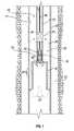
- Figure 1is a partial cross-sectional view of an example hydrocarbon recovery system disposed in a well bore and incorporating an injection system in accordance with an embodiment of the present disclosure
- Figure 2is a partial cross-sectional view of the exemplary injection system of Figure 1 in accordance with an embodiment of the present disclosure
- Figure 3is a partial cross-sectional view of another embodiment of an injection system in accordance the present disclosure.
- Figure 4is a partial cross-sectional view of the exemplary injection system of Figure 3 having an exemplary drain valve shown in an open position in accordance with an embodiment of the present disclosure
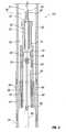
- Figure 5is a partial cross-sectional view of the exemplary injection system of Figure 3 shown deployed in an example hydrocarbon recovery system disposed in a well bore in accordance with an exemplary embodiment of the present disclosure
- Figure 6is an isolated view of another embodiment of an injection system in accordance with the present disclosure shown before final assembly;
- Figure 7is partial cut-away view of the exemplary injection system of Figure 6 shown assembled.
- Figure 8is a partial cross-sectional view of the exemplary injection system of Figure 6 shown deployed in an example hydrocarbon recovery system disposed in a well bore in accordance with an exemplary embodiment of the present disclosure.
- an example hydrocarbon recovery system 20is shown deployed in a subterranean well bore 21.
- the illustrated well bore 21includes a casing 26 emplaced with cement 23 and perforated with perforations 28.
- the perforations 28may run along the casing 26 at any desired interval. Such an interval, for example, could be from 100 (30.5m) to 3000 feet (914.4m) or more depending on the length of the hydrocarbon-bearing formation(s).
- the casing 26may have been perforated by a variety of methods as would be appreciated by one of ordinary skill in the art.
- cased well bore 21is provided for illustrative purposes only, as the subject matter of the present disclosure is applicable in any other suitable downhole environment, such as open well bores, as would be recognized by one of ordinary skill in the art.
- the hydrocarbon recovery system 20includes a production tubing 22 along with a perforated sub, or perforated portion, 24 and a dead string, or dead string portion, 32 run down hole inside the well bore 21.
- the production tubing 22, perforated sub 24 and dead string 32are constructed, configured and operate as is and becomes known in the art. Any suitable attachment mechanism may be utilized for connecting the production tubing 22, perforated sub 24 and dead string 32.
- the perforated sub 24is shown attached to the end of the production tubing 22 and the dead string 32 attached below the perforated sub 24.
- a plurality of perforations 30are located in the perforated sub 24 and allow for the flow of fluid, such as production fluids, into the production tubing 22, as understood by those skilled in the art.
- the perforations 30may be formed directly into the production tubing 22 or other component, alleviating the need for a separate perforated sub 24.
- the dead string portion 32may be an extension of the production tubing 22, or have any other configuration suitable to serve as a dead string, as is and becomes known.
- an "X" nipplemay be run on top of the perforated sub 24 for any number of reasons, such as, for example, sealing the production tubing 22 during retrieval operations, or for future installation of a plunger lift bumper spring (not shown), as understood by those skilled in the art.
- the perforated sub 24is shown positioned in the well bore 21 at a location above the perforations 28 in the casing 26.
- the perforated sub 24could be located along the perforations 28, with the goal that all fluids and gases move up or cross ways, but not downward.
- the dead string 32is shown extending from the top to the bottom of the illustrated perforations 28 in the casing 26.
- the exemplary dead string 32may extend, for example, a length of 3,000 foot (914.4m) or more.
- the dead string 32may extend any length along one or more sets of perforations 28, as desired.
- an injection system 36is shown run inside the internal bore of production tubing 22.
- the exemplary system 36is releasably engageable with the hydrocarbon recovery system 20 and capable of injecting fluid therethrough into the dead string portion 32 and/or well bore 21.
- the fluidmay be any desired treatment or other chemical(s), or any other one or more liquid, gas or fluid/particle mixture.
- the present disclosureinvolves the injection of fluids (not shown) above the dead string portion 32.
- the present disclosureinvolves systems 36 (not shown) capable of inserting equipment into the hydrocarbon recovery system 20.
- the system 36may carry any desired equipment, such as sensors, gages, fiber optics or electrical conductors, that may be used to perform one or more downhole operation. Accordingly, neither the type of "fluid” that is deliverable through the system 36, the type of equipment that may be carried by the system 36 nor any other characteristics thereof is limiting upon the present disclosure or the appended claims.
- the illustrated injection system 36includes at least one interconnected delivery tubing 34, such as capillary or coiled tubing, and at least one stopper 35 associated therewith. Fluid may be ejectable from the tubing 34 in any suitable manner. Typically, fluid may be ejected at one or more injection or ejection point at or proximate to the lower end 55 of the tubing 34.
- the tubing 34may be open-ended, or include one or more fluid ejection orifice (not shown), or one or more jetting, back pressure, check valve or other device (not shown) useful to assist in ejecting fluid as desired.
- at least one injector 60is shown disposed proximate to the lower end 55 of the delivery tubing 34 to assist in ejecting fluid therefrom. It should be understood, however, that the use of an injector 60 is not required for every embodiment.
- the outer diameters of the illustrated tubing 34, stopper 35 and injector 60 (if included), as well as any equipment (not shown) that may be carried by the tubing 34are typically all smaller than the inner diameter of the production tubing 22, perforated portion 24 and, in the illustrated embodiment, the dead string portion 32, so that the injection system 36 is capable of being moved into and out of the hydrocarbon recovery system 20 at least substantially independent of movement of the system 20.
- removal of the injection system 36 from the hydrocarbon recovery system 20allows the insertion of other equipment or tools (not shown) as desired into the production tubing 22 or the performance of other functions in the well, such as conducting a gage ring run, production logging and total depth tagging, and (ii) allows the components of the injection system 36 to be repaired, replaced, maintained or reconfigured, such as, for example, to clear a blockage therein or modify the deployed positioning of the injector 60, as will be described further below, all without having to remove the production tubing 22 from the well bore 21, killing the well or employing a work-over rig.
- the exemplary stopper 35is capable of preventing fluid flow between the respective bores of the production tubing 22 and dead string portion 32 when the injection system 36 is engaged with the hydrocarbon recovery system 20.
- the exemplary stopper 35By fluidly isolating the dead string 32 from the production tubing 22 (and perforated sub 24), the exemplary stopper 35 essentially causes the dead string portion 32 to function as a dead string. Since the illustrated stopper 35 is coupled to the delivery tubing 34 and thus integral with the injection system 36, disengagement of the system 36 from the hydrocarbon recovery system 20 removes the obstruction or seal caused by the stopper 35, effectively opening the dead string and allowing communication between the respective bores of the production tubing 22 and the dead string 32.
- the illustrated injector 60is fluidly coupled to the delivery tubing 34 at a desired location below the stopper 35 and positionable at a desired location within or down hole of the dead string portion 32 when the system 36 is deployed.
- the injector 60is shown positioned near the top of the dead string 32.
- the injector 60is shown positioned at the lower end of the dead string 32 and, in the embodiment of Figure 8 , below the lower end of the dead string 32.
- the exemplary injector 60when included, is thus capable of ejecting fluid from the delivery tubing 34 at any desired location within or below the dead string 32.
- chemicalssuch as scale inhibitors, foamers or other fluids or fluid/particle mixtures
- the delivery tubing 34may be injected downhole via the delivery tubing 34 and released at a desired location below the stopper 35 via the injector 60.
- Arrows 29illustrate the path of the fluids exiting the example injection system 36.
- the well bore 21may be treated from the bottom perforation 28 up as the injected chemicals travel up the annulus between the dead string 32 and the well bore 21 along the perforations 28, thereafter entering the sub perforations 30 and traveling back up through production tubing 22.
- the injector 60(or other fluid ejection device or feature) may be positioned, or fluidly coupled to the delivery tubing 34, at a desired location above the stopper 35 and positionable at a desired location within the production tubing 22 when the system 36 is deployed.
- the injection system 36is releasably sealingly engageable with a seat, or landing, nipple 38 shown attached to the bottom of the perforated sub 24.
- the seat nipple 38may be provided at any desired location relative to the production tubing 22 ( Figure 1 ) and dead string 32.
- the seat nipple 38may be connected in the production tubing 22 at a desired position below the perforations 30, or at a desired position in the dead string 32.
- the seat nipple 38is connected deep along the length of the dead string portion 32, which has an outer diameter equal to that of the production tubing 22.
- a seat nipple 38is provided, those ordinarily skilled in the art will appreciate that a variety of nipples or other components or features may instead be utilized.
- the stopper 35 and injector 60may have any suitable construction, configuration, form and operation.
- the injector 60may be an injection mandrel that includes one or more check valves 64 within its inner bore to prevent fluids from traveling up the injector 60.
- the injector 60may be constructed and operate as disclosed in U.S. Patent No. 6,880,639 entitled "Downhole Injection System” and issued on April 19, 2005, which is commonly owned by the assignee of the present invention, BJ Services Company of Houston, Texas and is hereby incorporated by reference in its entirety.
- the injector 60may be a dissolvable device, such as a one-way aluminum mandrel (not shown).
- the injector 60may include a single barrier check-valve, such as a ball-seat arrangement.
- the illustrated stopper 35includes a housing 41 through which the delivery tubing 34 extends or fluidly connects and which lands inside the seat nipple 38.
- the lower inner bore of seat nipple 38includes a shoulder 42 upon which the housing 41 (as well as other equipment) may land.
- the outer surface of the housing 41includes a plurality of annular grooves 44 at the lower end thereof.
- Seals 46may be placed inside the grooves 40 for sealing between the outer diameter of the housing 41 and the nipple 38, thereby essentially sealing off the dead string 32.
- the seals 46may be made using any variety of suitable materials such as, for example, Teflon. Although three seals 46 are shown, more or less seals 46 may be included as necessary for the given downhole pressure environment or other reasons. It should be noted, however, that any other suitable mechanism and technique for forming a fluid seal between the housing 41 and seat nipple 38 may be used.
- the housing 41instead includes an engagement portion 66 having a conical, or tapered, outer surface 68 which sealingly engages a correspondingly tapered portion 37 of the bore 39 of the nipple 38.
- the illustrated engagement portion 66is a metal (such as brass) sleeve that forms a metal-to-metal seal with the wall of the bore 47. Accordingly, the components and techniques for releasably landing and sealing the injection system 36 relative to the hydrocarbon recovery system 20 are not limiting upon the present disclosure.
- the housing 41may have any suitable components, configuration and operation.
- the illustrated housing 41includes an upper opening 45, a central bore 47, a seat 56 extending into the bore 47 and at least one side vent 43 located proximate to its upper end.
- the central bore 47is in fluid communication with the bore 39 of the nipple 38 and, ultimately, the production tubing 22 ( Figure 1 ) via the vents 43, and with the dead string 32 at its lower end.
- a valve member 40is shown disposed within the bore 47 of the housing 41 above the seat 56 with which it is sealingly engageable.
- the valve member 40is driven by a stem 50, which extends through and is movable within the upper opening 45 of the housing 41.
- valve member 40 and stem 50may have any suitable construction, configuration and operation.
- the valve member 40may be a ball, or partial ball, type member and the stem 50 may be a fishing neck, as are and become known in the art.
- the exemplary valve member 40 and stem 50include respective central bores 49, 52 for fluid communication with the delivery tubing 34.
- the housing 41, valve member 40 and stem 50may together comprise a standing valve and may be constructed of commercially available components, such as the presently known H-F Tubing Test Valve by Harbison Fisher. Further, the valve function of the housing 41 may be used for any desired purpose, as is or becomes known. In the example of Figure 2 , the housing 41 co-acts with the valve member 40 to provide a fluid drain, or hydrostatic pressure relief, function during retrieval of the injection system 36. This feature may be especially useful to assist in removal of the injection system 36 when the stopper 35 is landed deep within the well bore 21 (e.g. Figure 5 ). In fact, this feature may be instrumental in retrieving the injection system 36 at depths of 3,000 feet (914.4m) or more.
- valve member 40when the injection system 36 is engaged with the hydrocarbon recovery system 20 in the well bore 21 ( Figure 1 ), the valve member 40 is biased in a closed position. In the closed position, the valve member 40 essentially seals the bore 47 of the housing 41, assisting in sealing off the dead string 32 from the production tubing 22. (See also, e.g. Figure 3 ).
- the illustrated valve member 40is movable from a closed position to an open position with the application of pulling force upon the stem 50. In the open position, the valve member 40 allows fluid drainage from inside the production tubing 22 above the stopper 35 down through the vents 43 of the housing 41, into the bore 39 of the nipple 38 and into the dead string portion 32.
- valve member 40is shown in an open position and the path of the draining fluid is shown with arrows 72.
- any other suitable valve or drain techniques or componentsmay be used.
- a valve or drain capabilitymay not be included.
- the stopper 35includes a plug 74 that sealingly engages and seals off the bore 47 of the housing 41, such as with the use of one or more O-ring seal 78 or other suitable arrangement.
- the delivery tubing 34may be engaged with the stopper 35 and injector 50 (when included) in any suitable manner and with any desired components.
- a first, or upper, section 51 of the tubing 34is coupled to the top of the stem 50 of the valve member 40.
- This connectioncan be, for example, with the use of an NPT X compression fitting 48.
- a second, or lower, section 58 of the tubing 34is coupled to the bottom of the valve member 40, such as with a compression fitting 54, thereby establishing fluid communication with the first section 51 of the tubing 34 through the respective bores 49, 52 of the valve member 40 and stem 50.
- This connectioncan also be, for example, with the use of an NPT X compression fitting 48.
- first and second sections 51, 58connect directly to the plug 74.
- An upper slip 80is shown engaging the first section 51, while a lower slip engages the second section 58.
- a fishing neck 80threadably connects with the housing over the plug 74, retaining the various components in generally fixed relationship to each other.
- the first section 51 of tubing 34may extend to the surface and fluidly communicate with a chemical (or other fluid, fluid/particle mixture etc.) supply source (not shown) and the second section 58 connects to the injector 60, such as with another NPT X compression fitting 62.
- the second section 58can be switched out to vary the target deployed location of the injector 60 and fluid injection point within or below the dead string portion 32. (This is also possible with embodiments that do not include an injector 60.)
- the injector 60or fluid injection point(s) (not shown) of the delivery tubing 34, may be placed attached above the stopper 35.
- a compression fittingmay be needed for both the upper and lower ends of the injector 60.
- the upper compression fittingcould attach to the first section 51 of delivery tubing 34, while the lower compression fitting (not shown) would attach to another section of delivery tubing, which in turn will be connected to the compression fitting 48.
- the hydrocarbon recovery system 20may be run into the well bore 21. This includes, in this example, running the production tubing 22, perforated section or sub 24, seat nipple 38 and dead string portion 32.
- the injection system 36is run inside the tubing 22 and the stopper 35 is landed in the seat nipple 38, plugging off and sealing the dead string portion 32.
- stopper 35once the stopper 35 has been landed, it will seal off the lower section of the hydrocarbon recovery system 20, thereby effectively creating the dead string by fluidly isolating the dead string portion 32, simplifying the sealing process. Once the system 36 is in place, hydrocarbon fluid production may begin.
- chemicals or other desired fluidmay be communicated down hole via the delivery tubing 34 and injector 60.
- the chemicalssince they are injected via the injector 60 below the stopper 35, the chemicals should move along flow path 29 ( Figure 1 ) down through the dead string 32, sweeping across and effectively treating the perforations 28 and flowing back up through the sub perforations 30 into and up the production tubing 22.
- the chemicalsmay be used to also treat the production tubing 22 during that return flow.
- the length of the tubing 34may be selected to target the injection point within or below the dead string 32.
- the tubing 34is sized to position the injector 60 at the lower end of the dead string 32 and, in the embodiment of Figure 8 , below the lower end of the dead string 32.
- the flow path of the injected fluid, in each instance,is shown with arrows 29.
- an overpullmay be applied to the delivery tubing 34.
- the stopper 35will be removed from the seat nipple 38 and, along with the tubing 34 and injector 60, may then be pulled uphole through the production tubing 22 and back to the surface.
- Well pressure during retrievalmay be controlled using a capillary surface snubbing unit, as is and becomes known by those skilled in the art.
- Disengagement of the stopper 35 and extraction of the injection system 36opens the bore of the dead string portion 32 to the production tubing 22, allowing other down hole operations, if desired. Thereafter, the system 36 may be reinstalled into the hydrocarbon recovery system 20.
- This exemplary method of the present disclosurealleviates the need to remove the entire production tubing 22 and dead string 32 in order to access the well bore 21 and components of the hydrocarbon recovery system 20 and injection system 36.
- the second section 58 of delivery tubing 34may be switched out and replaced with a shorter or longer section 58 to facilitate the injection of fluid through the injector 60 at a different location within or below the dead string portion 32 after the system 36 is redeployed.
- the present disclosurewill allow for a through-tubing operation that is easily removed and replaced, thereby greatly reducing the required hardware and expense associated with such operations.
- the deficiencies associated with strappingmay be alleviated.
- the production tubing 22may be snubbed live.
- Preferred embodiments of the present disclosurethus offer advantages over the prior art and are well adapted to carry out one or more of the objects of this disclosure.
- the present inventiondoes not require each of the components and acts described above and is in no way limited to the above-described embodiments, methods of operation, variables, values or value ranges. Any one or more of the above components, features and processes may be employed in any suitable configuration without inclusion of other such components, features and processes.
- the present inventionincludes additional features, capabilities, functions, methods, uses and applications that have not been specifically addressed herein but are, or will become, apparent from the description herein, the appended drawings and claims.
Landscapes
- Geology (AREA)
- Life Sciences & Earth Sciences (AREA)
- Engineering & Computer Science (AREA)
- Mining & Mineral Resources (AREA)
- Geochemistry & Mineralogy (AREA)
- Fluid Mechanics (AREA)
- Environmental & Geological Engineering (AREA)
- General Life Sciences & Earth Sciences (AREA)
- Physics & Mathematics (AREA)
- Organic Low-Molecular-Weight Compounds And Preparation Thereof (AREA)
- Production Of Liquid Hydrocarbon Mixture For Refining Petroleum (AREA)
- Loading And Unloading Of Fuel Tanks Or Ships (AREA)
- Pipe Accessories (AREA)
- Catching Or Destruction (AREA)
- Decoration Of Textiles (AREA)
- Consolidation Of Soil By Introduction Of Solidifying Substances Into Soil (AREA)
Abstract
Description
- The present disclosure relates generally to dead string completion technology and, more particularly, apparatus and methods relating to the injection of fluid or insertion of equipment into a subterranean well through a dead sting assembly.
- In typical hydrocarbon recovery completion systems, the production tubing is suspended in the casing and terminates above the top perforation. By terminating the production tubing above the top perforation, such as at 100 feet (30.5m) or more, the cased section of the well adjacent to the perforations has a larger diameter than the cased section adjacent to the production tubing. The larger diameter of the cased section adjacent to the perforations severely reduces the velocity of the production liquids exiting the perforations, which in turn may create liquid loading, a situation where the liquids settle at the bottom of the casing because the velocity is not sufficient enough to lift the fluids. Often, extremely long perforated casing intervals, sometimes 3,000 feet (914.4m) or more, are exposed to longer sections of low velocities, again increasing the inevitable liquid loading phenomena.
- In recent years, "dead string" completion have been embraced by many operators in order to combat the phenomena of liquid loading. Such an assembly is disclosed in
US Patent 2007/158074 which is considered the closest prior art document to the subject-matter ofclaim 1. The typical dead string completion consists of a perforated sub connected to the bottom of the production tubing, and a tubing extending from the perforated sub down into the perforated casing interval. The tubing extending down from the perforated sub is plugged, hence the term "dead string", and can have a larger or smaller diameter than that of the production tubing. As such, the dead string portion essentially reduces the flow area within the adjacent casing interval, thereby increasing the velocity of the fluid flow and enhancing hydrocarbon production over the life cycle of the well. - Current dead string assemblies are also often used to introduce chemicals down hole. These chemicals, such as scale inhibitors, are delivered from the surface to the perforated sub and ultimately to the perforated casing to perform their desired function. Various techniques have been used and proposed for delivering the chemicals. For example, chemicals have been introduced by "strapping" a capillary tubing to the outer diameter of the production tubing with bands while a workover rig is installing the production tubing. The capillary tubing is coupled to a cross over sub to introduce the chemicals to the inside diameter of the dead string through a chemical injection valve and, hopefully, out into the annulus between the dead string and the casing to treat the well across the entire perforated interval.
- Presently known techniques for providing chemicals (or any other desired liquids, gasses, equipment or a combination thereof) via a dead string completion assembly may have one or more drawbacks. For example, it may not be possible to snub the well live due to the capillary string and bands (i.e., strapping) on the outer diameter of the production tubing. In such instance, in order to accommodate the strapping of the capillary tubing to the production tubing, the well must be killed and heavy hydrostatic fluids, which may cause damage to the formation, may need to be used. For another possible example, should the capillary become plugged or the chemical injection system become inoperable, the well must be killed again in order to pull the entire production string for repair and/or replacement of the capillary line. For yet another potential example, in the case of backside capillary lines, the strapped capillary must penetrate the tubing hanger - which can be a costly endeavor.
- It should be understood that the above-described discussion is provided for illustrative purposes only and is not intended to limit the scope or subject matter of the appended claims or those of any related patent application or patent. Thus, none of the appended claims or claims of any related application or patent should be limited by the above discussion or construed to address, include or exclude the cited examples, features and/or disadvantages, merely because of the mention thereof above.
- Accordingly, there exists a need for improved systems, apparatus and methods capable of injecting any desired fluid(s) or inserting equipment into a subterranean well through a dead string completion assembly having one or more of the attributes or capabilities described below or evident from the appended drawings.
- In some embodiments, the present disclosure involves apparatus useful for providing fluids into a subterranean well through a hydrocarbon recovery system deployable in the well. The hydrocarbon recovery system may include at least one production tubing and associated dead string portion. The dead string portion is located below the production tubing and both the production tubing and dead string portion have at least one bore extending longitudinally therethrough. The production tubing includes at least one perforated portion that allows the entry of fluids into the bore thereof from the well when the production tubing is deployed in the well. The apparatus of these embodiments includes an injection system releasably engageable with the hydrocarbon recovery system and configured to be movable into and out of the well and the production tubing at least substantially independent of movement of the hydrocarbon recovery system.
- The injection system of these embodiments includes at least one delivery tubing and stopper. The delivery tubing has an outer diameter that is smaller than the inner diameters of the production tubing and dead string portion. The stopper is connected with the delivery tubing and configured to prevent fluid flow between the respective bores of the production tubing and dead string portion when the injection system is engaged with the hydrocarbon recovery system. The delivery tubing extends below the stopper and allows fluid to be ejected therefrom at a desired location within or below the dead string portion when the injection system is engaged with the hydrocarbon recovery system.
- When the hydrocarbon recovery system is deployed in the well, the injection system of these embodiments may be engaged and disengaged with and removable from the hydrocarbon recovery system without removing the hydrocarbon recovery system from the well. Engagement of the injection system with the hydrocarbon recovery system fluidly isolates the production tubing and dead string portion, while disengagement thereof allows fluid communication between the respective bores of the production tubing and the dead string portion.
- In some embodiments, the present disclosure includes a delivery tubing configured to allow fluid to be ejected therefrom into the production tubing at a location above the stopper when the injection system is engaged with the hydrocarbon recovery system in the well.
- The present disclosure also includes some embodiments which involve a chemical injection system capable of providing chemicals into a subterranean well having at least one connected production tubing, perforated sub, dead string and landing nipple. The chemical injection system includes at least one interconnected upper and capillary tubing, stopper and injector. The upper capillary tubing is in fluid communication with a chemical supply source. The stopper is releasably sealingly engageable within the landing nipple and capable of releasably fluidly isolating the respective bores of the production tubing and dead string. The lower capillary tubing is in fluid communication with the upper capillary tubing and at least partially insertable into the bore of the dead string. The injector is disposed at or proximate to the lower end of the lower capillary tubing and is positionable and capable of ejecting chemicals supplied through the upper and lower capillary tubings below the top of the dead string. The upper and lower capillary tubings, stopper and injector are together insertable into and removable from the bore of the production tubing without removing the production tubing from the well. There are also embodiments of the present disclosure that involve apparatus useful for providing equipment into a subterranean well through a hydrocarbon recovery system deployable in the well. The hydrocarbon recovery system may include at least one production tubing and associated dead string portion. The dead string portion is located below the production tubing and both the production tubing and dead string portion have at least one bore extending longitudinally therethrough. The production tubing includes at least one perforated portion that allows the entry of fluids into the bore thereof from the well when the production tubing is deployed in the well.
- In these embodiments, an injection system is releasably engageable with the hydrocarbon recovery system and configured to be movable into and out of the well and the production tubing at least substantially independent of movement of the hydrocarbon recovery system. The injection system includes at least one delivery tubing having upper and lower ends and an outer diameter that is smaller than the inner diameter of the production tubing and dead string portion. The delivery tubing is capable of carrying at least one item of equipment proximate to its lower end. At least one stopper is connected with the delivery tubing and configured to prevent fluid flow between the respective bores of the production tubing and dead string portion when the injection system is engaged with the hydrocarbon recovery system. The delivery tubing extends a desired distance below the stopper and is capable of positioning the equipment carried thereby at a location within the dead string portion or below the dead string portion when the injection system is engaged with the hydrocarbon recovery system in the well. When the hydrocarbon recovery system is deployed in the well, the injection system may be engaged and disengaged with and removable from the hydrocarbon recovery system without removing the hydrocarbon recovery system from the well. Engagement of the injection system with the hydrocarbon recovery system fluidly isolates the production tubing from the dead string portion and disengagement of the injection system from the hydrocarbon recovery system allows fluid communication between the production tubing and the dead string portion.
- In some embodiments, the present disclosure involves a method of providing chemicals into a subterranean well having a hydrocarbon recovery system disposed therein. The hydrocarbon recovery system includes at least one interconnected production tubing, dead string portion and seat nipple. The dead string portion is disposed down hole of the production tubing. The production tubing, dead string portion and seat nipple each have a bore extending longitudinally therethrough. The production tubing including at least one perforated portion or sub that allows the entry of fluids into the bore of the production tubing from the well.
- The method of these embodiments includes inserting an injection system into the production tubing from the surface, the injection system including at least one delivery tubing and stopper. At least substantially simultaneously, the stopper is seated within the seat nipple, fluidly isolating the respective bores of the production tubing and dead string at the location of the stopper, and at least one fluid ejection point is positioned at a desired location either within the bore of the dead string or below the lower end of the dead string. Chemicals are ejected from the delivery tubing at a desired location either within the bore of the dead string or below the lower end of the dead string. An overpull is applied to the delivery tubing and the fluid injection system is removed from the hydrocarbon recovery system and well, fluidly connecting the respective bores of the production tubing and dead string. The injection system is thus removable from the well without removing the hydrocarbon recovery system from the well.
- Accordingly, the present disclosure includes features and advantages which are believed to enable it to advance dead string completion technology. Characteristics and potential advantages of the present disclosure described above and additional potential features and benefits will be readily apparent to those skilled in the art upon consideration of the following detailed description of various embodiments and referring to the accompanying drawings.
- The following figures are part of the present specification, included to demonstrate certain aspects of various embodiments of this disclosure and referenced in the detailed description herein:
Figure 1 is a partial cross-sectional view of an example hydrocarbon recovery system disposed in a well bore and incorporating an injection system in accordance with an embodiment of the present disclosure;Figure 2 is a partial cross-sectional view of the exemplary injection system ofFigure 1 in accordance with an embodiment of the present disclosure;Figure 3 is a partial cross-sectional view of another embodiment of an injection system in accordance the present disclosure;Figure 4 is a partial cross-sectional view of the exemplary injection system ofFigure 3 having an exemplary drain valve shown in an open position in accordance with an embodiment of the present disclosure;Figure 5 is a partial cross-sectional view of the exemplary injection system ofFigure 3 shown deployed in an example hydrocarbon recovery system disposed in a well bore in accordance with an exemplary embodiment of the present disclosure;Figure 6 is an isolated view of another embodiment of an injection system in accordance with the present disclosure shown before final assembly;Figure 7 is partial cut-away view of the exemplary injection system ofFigure 6 shown assembled; andFigure 8 is a partial cross-sectional view of the exemplary injection system ofFigure 6 shown deployed in an example hydrocarbon recovery system disposed in a well bore in accordance with an exemplary embodiment of the present disclosure.- Characteristics and advantages of the present disclosure and additional features and benefits will be readily apparent to those skilled in the art upon consideration of the following detailed description of exemplary embodiments of the present disclosure and referring to the accompanying figures. It should be understood that the description herein and appended drawings, being of example embodiments, are not intended to limit the claims of this patent application, any patent granted hereon or any patent or patent application claiming priority hereto. On the contrary, the intention is to cover all modifications, equivalents and alternatives falling within the spirit and scope of the claims. Many changes may be made to the particular embodiments and details disclosed herein without departing from such spirit and scope.
- In showing and describing preferred embodiments, like or identical reference numerals are used to identify common or similar elements. The figures are not necessarily to scale and certain features and certain views of the figures may be shown exaggerated in scale or in schematic in the interest of clarity and conciseness.
- As used herein and throughout various portions (and headings) of this patent application, the terms "invention", "present invention" and variations thereof are not intended to mean every possible embodiment encompassed by this disclosure or any particular claim(s). Thus, the subject matter of each such reference should not be considered as necessary for, or part of, every embodiment hereof or of any particular claim(s) merely because of such reference. The terms "coupled", "connected", "engaged" and the like, and variations thereof, as used herein and in the appended claims are intended to mean either an indirect or direct connection or engagement. Thus, if a first device couples to a second device, that connection may be through a direct connection, or through an indirect connection via other devices and connections.
- Certain terms are used herein and in the appended claims to refer to particular components. As one skilled in the art will appreciate, different persons may refer to a component by different names. This document does not intend to distinguish between components that differ in name but not function. Also, the terms "including" and "comprising" are used herein and in the appended claims in an open-ended fashion, and thus should be interpreted to mean "including, but not limited to ...." Further, reference herein and in the appended claims to components and aspects in a singular tense does not necessarily limit the present disclosure or appended claims to onlyone such component or aspect, but should be interpreted generally to meanone or more, as may be suitable and desirable in each particular instance.
- Referring initially to
Figure 1 , an examplehydrocarbon recovery system 20 is shown deployed in a subterranean well bore 21. The illustrated well bore 21 includes acasing 26 emplaced withcement 23 and perforated withperforations 28. Theperforations 28 may run along thecasing 26 at any desired interval. Such an interval, for example, could be from 100 (30.5m) to 3000 feet (914.4m) or more depending on the length of the hydrocarbon-bearing formation(s). Thecasing 26 may have been perforated by a variety of methods as would be appreciated by one of ordinary skill in the art. It should be noted that the use of a cased well bore 21 is provided for illustrative purposes only, as the subject matter of the present disclosure is applicable in any other suitable downhole environment, such as open well bores, as would be recognized by one of ordinary skill in the art. - The
hydrocarbon recovery system 20 includes aproduction tubing 22 along with a perforated sub, or perforated portion, 24 and a dead string, or dead string portion, 32 run down hole inside the well bore 21. Theproduction tubing 22,perforated sub 24 anddead string 32 are constructed, configured and operate as is and becomes known in the art. Any suitable attachment mechanism may be utilized for connecting theproduction tubing 22,perforated sub 24 anddead string 32. - The
perforated sub 24 is shown attached to the end of theproduction tubing 22 and thedead string 32 attached below theperforated sub 24. A plurality ofperforations 30 are located in theperforated sub 24 and allow for the flow of fluid, such as production fluids, into theproduction tubing 22, as understood by those skilled in the art. However, theperforations 30 may be formed directly into theproduction tubing 22 or other component, alleviating the need for a separateperforated sub 24. Likewise, thedead string portion 32 may be an extension of theproduction tubing 22, or have any other configuration suitable to serve as a dead string, as is and becomes known. Although not illustrated, an "X" nipple may be run on top of theperforated sub 24 for any number of reasons, such as, for example, sealing theproduction tubing 22 during retrieval operations, or for future installation of a plunger lift bumper spring (not shown), as understood by those skilled in the art. - In
Figure 1 , theperforated sub 24 is shown positioned in the well bore 21 at a location above theperforations 28 in thecasing 26. In other examples, theperforated sub 24 could be located along theperforations 28, with the goal that all fluids and gases move up or cross ways, but not downward. Thus, if theperforated sub 24 was adjacent to the middle of theperforations 28, fluids from the uppermost perforations 28 would possibly have to travel downward to reach theperforated sub 24, which should preferably be avoided in the illustrated example. Also in this example, thedead string 32 is shown extending from the top to the bottom of the illustratedperforations 28 in thecasing 26. As such, the exemplarydead string 32 may extend, for example, a length of 3,000 foot (914.4m) or more. However, those skilled in the art realize thedead string 32 may extend any length along one or more sets ofperforations 28, as desired. - The above-referenced components and the operation thereof are known in the art and may have any suitable form, construction and configuration. Moreover, the above-referenced components and the operation thereof are not limiting upon the present invention or the appended claims. If desired, different or additional components, as are and become known in the art, may be used.
- Now in accordance with an embodiment of the present invention, referring still to
Figure 1 , aninjection system 36 is shown run inside the internal bore ofproduction tubing 22. Theexemplary system 36 is releasably engageable with thehydrocarbon recovery system 20 and capable of injecting fluid therethrough into thedead string portion 32 and/or well bore 21. The fluid may be any desired treatment or other chemical(s), or any other one or more liquid, gas or fluid/particle mixture. It should be noted, in other embodiments, the present disclosure involves the injection of fluids (not shown) above thedead string portion 32. In yet other embodiments, the present disclosure involves systems 36 (not shown) capable of inserting equipment into thehydrocarbon recovery system 20. For example, thesystem 36 may carry any desired equipment, such as sensors, gages, fiber optics or electrical conductors, that may be used to perform one or more downhole operation. Accordingly, neither the type of "fluid" that is deliverable through thesystem 36, the type of equipment that may be carried by thesystem 36 nor any other characteristics thereof is limiting upon the present disclosure or the appended claims. - The illustrated
injection system 36 includes at least oneinterconnected delivery tubing 34, such as capillary or coiled tubing, and at least onestopper 35 associated therewith. Fluid may be ejectable from thetubing 34 in any suitable manner. Typically, fluid may be ejected at one or more injection or ejection point at or proximate to thelower end 55 of thetubing 34. For example, thetubing 34 may be open-ended, or include one or more fluid ejection orifice (not shown), or one or more jetting, back pressure, check valve or other device (not shown) useful to assist in ejecting fluid as desired. In the illustrated embodiment, at least oneinjector 60 is shown disposed proximate to thelower end 55 of thedelivery tubing 34 to assist in ejecting fluid therefrom. It should be understood, however, that the use of aninjector 60 is not required for every embodiment. - The outer diameters of the illustrated
tubing 34,stopper 35 and injector 60 (if included), as well as any equipment (not shown) that may be carried by thetubing 34 are typically all smaller than the inner diameter of theproduction tubing 22, perforatedportion 24 and, in the illustrated embodiment, thedead string portion 32, so that theinjection system 36 is capable of being moved into and out of thehydrocarbon recovery system 20 at least substantially independent of movement of thesystem 20. In this embodiment, removal of theinjection system 36 from the hydrocarbon recovery system 20 (i) allows the insertion of other equipment or tools (not shown) as desired into theproduction tubing 22 or the performance of other functions in the well, such as conducting a gage ring run, production logging and total depth tagging, and (ii) allows the components of theinjection system 36 to be repaired, replaced, maintained or reconfigured, such as, for example, to clear a blockage therein or modify the deployed positioning of theinjector 60, as will be described further below, all without having to remove theproduction tubing 22 from the well bore 21, killing the well or employing a work-over rig. - Still referring to
Figure 1 , theexemplary stopper 35 is capable of preventing fluid flow between the respective bores of theproduction tubing 22 anddead string portion 32 when theinjection system 36 is engaged with thehydrocarbon recovery system 20. By fluidly isolating thedead string 32 from the production tubing 22 (and perforated sub 24), theexemplary stopper 35 essentially causes thedead string portion 32 to function as a dead string. Since the illustratedstopper 35 is coupled to thedelivery tubing 34 and thus integral with theinjection system 36, disengagement of thesystem 36 from thehydrocarbon recovery system 20 removes the obstruction or seal caused by thestopper 35, effectivelyopening the dead string and allowing communication between the respective bores of theproduction tubing 22 and thedead string 32. - The illustrated
injector 60 is fluidly coupled to thedelivery tubing 34 at a desired location below thestopper 35 and positionable at a desired location within or down hole of thedead string portion 32 when thesystem 36 is deployed. In this embodiment, theinjector 60 is shown positioned near the top of thedead string 32. In the example ofFigure 5 , theinjector 60 is shown positioned at the lower end of thedead string 32 and, in the embodiment ofFigure 8 , below the lower end of thedead string 32. Theexemplary injector 60, when included, is thus capable of ejecting fluid from thedelivery tubing 34 at any desired location within or below thedead string 32. As such, chemicals, such as scale inhibitors, foamers or other fluids or fluid/particle mixtures, may be injected downhole via thedelivery tubing 34 and released at a desired location below thestopper 35 via theinjector 60.Arrows 29 illustrate the path of the fluids exiting theexample injection system 36. As such, the well bore 21 may be treated from thebottom perforation 28 up as the injected chemicals travel up the annulus between thedead string 32 and the well bore 21 along theperforations 28, thereafter entering thesub perforations 30 and traveling back up throughproduction tubing 22. In other embodiments, the injector 60 (or other fluid ejection device or feature) may be positioned, or fluidly coupled to thedelivery tubing 34, at a desired location above thestopper 35 and positionable at a desired location within theproduction tubing 22 when thesystem 36 is deployed. - Any suitable technique and components may be included for releasably sealingly engaging the
injection system 36 with thehydrocarbon recovery system 20. In the embodiment ofFigure 2 , theinjection system 36 is releasably sealingly engageable with a seat, or landing,nipple 38 shown attached to the bottom of theperforated sub 24. However, theseat nipple 38 may be provided at any desired location relative to the production tubing 22 (Figure 1 ) anddead string 32. For example, depending upon the configuration of theproduction tubing 22 anddead string 32, theseat nipple 38 may be connected in theproduction tubing 22 at a desired position below theperforations 30, or at a desired position in thedead string 32. In the embodiment ofFigure 5 , for example, theseat nipple 38 is connected deep along the length of thedead string portion 32, which has an outer diameter equal to that of theproduction tubing 22. Further, although aseat nipple 38 is provided, those ordinarily skilled in the art will appreciate that a variety of nipples or other components or features may instead be utilized. - The
stopper 35 and injector 60 (when included) may have any suitable construction, configuration, form and operation. For example, referring to the embodimentFigure 2 , theinjector 60 may be an injection mandrel that includes one ormore check valves 64 within its inner bore to prevent fluids from traveling up theinjector 60. If desired, theinjector 60 may be constructed and operate as disclosed inU.S. Patent No. 6,880,639 entitled "Downhole Injection System" and issued on April 19, 2005, which is commonly owned by the assignee of the present invention, BJ Services Company of Houston, Texas and is hereby incorporated by reference in its entirety. For another example, theinjector 60 may be a dissolvable device, such as a one-way aluminum mandrel (not shown). For yet another example, theinjector 60 may include a single barrier check-valve, such as a ball-seat arrangement. - Still referring to the embodiment of
Figure 2 , the illustratedstopper 35 includes ahousing 41 through which thedelivery tubing 34 extends or fluidly connects and which lands inside theseat nipple 38. In this example, the lower inner bore ofseat nipple 38 includes ashoulder 42 upon which the housing 41 (as well as other equipment) may land. Once the illustratedhousing 41 is inserted into thenipple 38, the bottom end ofhousing 41 rests atop theshoulder 42, thereby setting thehousing 41 in the desired location. In other embodiments, different configurations of landing mechanisms and techniques may be utilized such as, for example, locking profiles and/or locking dogs. - In this example, the outer surface of the
housing 41 includes a plurality ofannular grooves 44 at the lower end thereof.Seals 46 may be placed inside thegrooves 40 for sealing between the outer diameter of thehousing 41 and thenipple 38, thereby essentially sealing off thedead string 32. Theseals 46 may be made using any variety of suitable materials such as, for example, Teflon. Although threeseals 46 are shown, more orless seals 46 may be included as necessary for the given downhole pressure environment or other reasons. It should be noted, however, that any other suitable mechanism and technique for forming a fluid seal between thehousing 41 andseat nipple 38 may be used. For example, in the embodiment ofFigure 3 , thehousing 41 instead includes anengagement portion 66 having a conical, or tapered,outer surface 68 which sealingly engages a correspondingly tapered portion 37 of thebore 39 of thenipple 38. The illustratedengagement portion 66 is a metal (such as brass) sleeve that forms a metal-to-metal seal with the wall of thebore 47. Accordingly, the components and techniques for releasably landing and sealing theinjection system 36 relative to thehydrocarbon recovery system 20 are not limiting upon the present disclosure. - Referring again to the embodiment of
Figure 2 , thehousing 41 may have any suitable components, configuration and operation. The illustratedhousing 41 includes anupper opening 45, acentral bore 47, aseat 56 extending into thebore 47 and at least oneside vent 43 located proximate to its upper end. At its upper end, thecentral bore 47 is in fluid communication with thebore 39 of thenipple 38 and, ultimately, the production tubing 22 (Figure 1 ) via thevents 43, and with thedead string 32 at its lower end. Avalve member 40 is shown disposed within thebore 47 of thehousing 41 above theseat 56 with which it is sealingly engageable. Thevalve member 40 is driven by astem 50, which extends through and is movable within theupper opening 45 of thehousing 41. - The illustrated
valve member 40 and stem 50 may have any suitable construction, configuration and operation. For example, thevalve member 40 may be a ball, or partial ball, type member and thestem 50 may be a fishing neck, as are and become known in the art. Theexemplary valve member 40 and stem 50 include respectivecentral bores delivery tubing 34. - The
housing 41,valve member 40 and stem 50 may together comprise a standing valve and may be constructed of commercially available components, such as the presently known H-F Tubing Test Valve by Harbison Fisher. Further, the valve function of thehousing 41 may be used for any desired purpose, as is or becomes known. In the example ofFigure 2 , thehousing 41 co-acts with thevalve member 40 to provide a fluid drain, or hydrostatic pressure relief, function during retrieval of theinjection system 36. This feature may be especially useful to assist in removal of theinjection system 36 when thestopper 35 is landed deep within the well bore 21 (e.g.Figure 5 ). In fact, this feature may be instrumental in retrieving theinjection system 36 at depths of 3,000 feet (914.4m) or more. - Still referring to the embodiment of
Figure 2 , when theinjection system 36 is engaged with thehydrocarbon recovery system 20 in the well bore 21 (Figure 1 ), thevalve member 40 is biased in a closed position. In the closed position, thevalve member 40 essentially seals thebore 47 of thehousing 41, assisting in sealing off thedead string 32 from theproduction tubing 22. (See also, e.g.Figure 3 ). When desired, the illustratedvalve member 40 is movable from a closed position to an open position with the application of pulling force upon thestem 50. In the open position, thevalve member 40 allows fluid drainage from inside theproduction tubing 22 above thestopper 35 down through thevents 43 of thehousing 41, into thebore 39 of thenipple 38 and into thedead string portion 32. For example, inFigure 4 , the illustratedvalve member 40 is shown in an open position and the path of the draining fluid is shown witharrows 72. However, any other suitable valve or drain techniques or components may be used. Further, in some embodiments, a valve or drain capability may not be included. For example, in the embodiment ofFigures 6-8 , thestopper 35 includes aplug 74 that sealingly engages and seals off thebore 47 of thehousing 41, such as with the use of one or more O-ring seal 78 or other suitable arrangement. - Referring again to
Figure 2 , thedelivery tubing 34 may be engaged with thestopper 35 and injector 50 (when included) in any suitable manner and with any desired components. In this embodiment, a first, or upper,section 51 of thetubing 34 is coupled to the top of thestem 50 of thevalve member 40. This connection can be, for example, with the use of an NPTX compression fitting 48. A second, or lower,section 58 of thetubing 34 is coupled to the bottom of thevalve member 40, such as with acompression fitting 54, thereby establishing fluid communication with thefirst section 51 of thetubing 34 through the respective bores 49, 52 of thevalve member 40 andstem 50. This connection can also be, for example, with the use of an NPTX compression fitting 48. - In the example of
Figure 6 , the first andsecond sections plug 74. Anupper slip 80 is shown engaging thefirst section 51, while a lower slip engages thesecond section 58. Afishing neck 80 threadably connects with the housing over theplug 74, retaining the various components in generally fixed relationship to each other. In both embodiments, thefirst section 51 oftubing 34 may extend to the surface and fluidly communicate with a chemical (or other fluid, fluid/particle mixture etc.) supply source (not shown) and thesecond section 58 connects to theinjector 60, such as with another NPTX compression fitting 62. Upon retrieval of theinjection system 36 from the well bore 21, in both examples, thesecond section 58 can be switched out to vary the target deployed location of theinjector 60 and fluid injection point within or below thedead string portion 32. (This is also possible with embodiments that do not include aninjector 60.) - In other embodiments, although now shown, the
injector 60, or fluid injection point(s) (not shown) of thedelivery tubing 34, may be placed attached above thestopper 35. In such instance, a compression fitting may be needed for both the upper and lower ends of theinjector 60. For example, the upper compression fitting (not shown) could attach to thefirst section 51 ofdelivery tubing 34, while the lower compression fitting (not shown) would attach to another section of delivery tubing, which in turn will be connected to thecompression fitting 48. - An embodiment of a method of operation in accordance with the present disclosure will now be described with reference to the examples of
Figures 1 and2 . However, neither this embodiment nor other methods of the present disclosure are limited to use with the illustrated components; any suitable components or physical embodiments may be used. After thecasing 26 has been run down hole, thehydrocarbon recovery system 20 may be run into the well bore 21. This includes, in this example, running theproduction tubing 22, perforated section orsub 24,seat nipple 38 anddead string portion 32. Theinjection system 36 is run inside thetubing 22 and thestopper 35 is landed in theseat nipple 38, plugging off and sealing thedead string portion 32. In this embodiment, once thestopper 35 has been landed, it will seal off the lower section of thehydrocarbon recovery system 20, thereby effectively creating the dead string by fluidly isolating thedead string portion 32, simplifying the sealing process. Once thesystem 36 is in place, hydrocarbon fluid production may begin. - Should the need arise to treat the
perforations 28 or for any other purpose, chemicals or other desired fluid may be communicated down hole via thedelivery tubing 34 andinjector 60. In the case of treatment chemicals, since they are injected via theinjector 60 below thestopper 35, the chemicals should move along flow path 29 (Figure 1 ) down through thedead string 32, sweeping across and effectively treating theperforations 28 and flowing back up through thesub perforations 30 into and up theproduction tubing 22. If desired, the chemicals may be used to also treat theproduction tubing 22 during that return flow. - It should be noted that the length of the
tubing 34 may be selected to target the injection point within or below thedead string 32. InFigure 5 , for example, thetubing 34 is sized to position theinjector 60 at the lower end of thedead string 32 and, in the embodiment ofFigure 8 , below the lower end of thedead string 32. The flow path of the injected fluid, in each instance, is shown witharrows 29. - Referring again to the example of
Figures 1 and2 , in the event of a need to remove thedelivery tubing 34 or theinjection system 36, an overpull may be applied to thedelivery tubing 34. Once overpulled, thestopper 35 will be removed from theseat nipple 38 and, along with thetubing 34 andinjector 60, may then be pulled uphole through theproduction tubing 22 and back to the surface. Well pressure during retrieval may be controlled using a capillary surface snubbing unit, as is and becomes known by those skilled in the art. Disengagement of thestopper 35 and extraction of theinjection system 36 opens the bore of thedead string portion 32 to theproduction tubing 22, allowing other down hole operations, if desired. Thereafter, thesystem 36 may be reinstalled into thehydrocarbon recovery system 20. - With the use of the embodiment of
Figure 2 , before theinjection system 36 is removed, if desired, hydrostatic pressure upon thesystem 36 may be relieved. In this example, sufficient overpull is applied to draw the stem, or fishing neck, 50 of thevalve member 40 up a limited distance (e.g., 2 inches) to lift thevalve member 40 from theseat 56. This will allow fluid to drain from theproduction tubing 22 andseat nipple 38 above thestopper 35 into thevents 43, past thevalve member 40 and theseat 56, into thebore 39 of the nipple and into thedead string 32. This drain feature may be especially useful when thestopper 35 andinjector 60 are located deep within the well bore 21. In fact, this feature may facilitate the and retrieval of theinjection system 36 at depths of 3,000 feet (914.4m) or more without having to remove theproduction tubing 22 from the well bore 21, kill the well or employ a work-over rig. - This exemplary method of the present disclosure alleviates the need to remove the
entire production tubing 22 anddead string 32 in order to access the well bore 21 and components of thehydrocarbon recovery system 20 andinjection system 36. For example, upon removal of theinjection system 36, thesecond section 58 ofdelivery tubing 34 may be switched out and replaced with a shorter orlonger section 58 to facilitate the injection of fluid through theinjector 60 at a different location within or below thedead string portion 32 after thesystem 36 is redeployed. As such, the present disclosure will allow for a through-tubing operation that is easily removed and replaced, thereby greatly reducing the required hardware and expense associated with such operations. Further, in accordance with this exemplary method, since theinjection system 36 is run inside theproduction tubing 22, the deficiencies associated with strapping may be alleviated. By attaching thestopper 35 andinjector 60 to the bottom end of thedelivery tubing 34, theproduction tubing 22 may be snubbed live. - Preferred embodiments of the present disclosure thus offer advantages over the prior art and are well adapted to carry out one or more of the objects of this disclosure. However, the present invention does not require each of the components and acts described above and is in no way limited to the above-described embodiments, methods of operation, variables, values or value ranges. Any one or more of the above components, features and processes may be employed in any suitable configuration without inclusion of other such components, features and processes. Moreover, the present invention includes additional features, capabilities, functions, methods, uses and applications that have not been specifically addressed herein but are, or will become, apparent from the description herein, the appended drawings and claims.
Claims (15)
- Apparatus useful for providing fluid and/or equipment into a subterranean well through a hydrocarbon recovery system (20) deployable in the well (21), the hydrocarbon recovery system including at least one production tubing (22) and at least one dead string portion (32) associated therewith, the dead string portion being positioned below the production tubing, the production tubing and dead string portion each having at least one bore extending longitudinally therethrough, the production tubing including at least one perforated portion (24) that allows the entry of fluids into the bore of the production tubing from the well when the production tubing is deployed in the well, the apparatuscharacterised in that it further comprises:an injection system (36) releasably engageable with the hydrocarbon recovery system (20) and configured to be movable into and out of the well (21) and the production tubing (22) at least substantially independent of movement of the hydrocarbon recovery system, said injection system including
at least one delivery tubing (34) having an upper end, a lower end and an outer diameter that is smaller than the inner diameter of the production tubing and dead string portion, said delivery tubing being in fluid communication with a fluid supply source and/or capable of carrying at least one item of equipment,
at least one stopper (35) connected with said delivery tubing and configured to prevent fluid flow between the respective bores of the production tubing (22) and dead string portion (32) when said injection system (36) is engaged with the hydrocarbon recovery system,
and at least one of the following
wherein at least one said delivery tubing (34) extends a desired distance below said stopper (35) and is capable of positioning the equipment carried thereby at a location within the dead string portion (32) or below the dead string portion when said injection system (36) is engaged with the hydrocarbon recovery system in the well,
wherein at least one said delivery tubing (34) extends a desired distance below said stopper (35) and is configured to allow fluid to be ejected therefrom at a location within the dead string portion or below the dead string portion when said injection system is engaged with the hydrocarbon recovery system in the well,
wherein at least one said delivery tubing is configured to allow fluid to be ejected therefrom into the production tubing at a location above the stopper when said injection system is engaged with the hydrocarbon recovery system in the well;wherein when the hydrocarbon recovery system is deployed in the well, said injection system may be engaged and disengaged with and removable from the hydrocarbon recovery system without removing the hydrocarbon recovery system from the well, andwherein engagement of said injection system with the hydrocarbon recovery system fluidly isolates the production tubing from the dead string portion and disengagement of said injection system from the hydrocarbon recovery system allows fluid communication between the production tubing and the dead string portion. - The apparatus of claim 1 wherein said stopper (35) includes a housing assembly (41) releasably sealingly engageable with the hydrocarbon recovery system, said housing assembly having at least one bore (47) through which at least one said delivery tubing extends or fluidly communicates, said bore of said housing assembly being in fluid communication with the respective bores of the production tubing and dead string portion.
- The apparatus of claim 2 wherein said stopper (35) includes a plug (74) interconnected with said delivery tubing (34) and sealingly engageable within said bore of said housing assembly, said plug being capable of assisting in fluidly isolating the respective bores of the production tubing and dead string portion when said plug is sealingly engaged within said housing assembly.
- The apparatus of claim 2 wherein said stopper includes at least one valve (40) disposed at least partially within said housing assembly and moveable between open and closed positions relative to said bore of said housing assembly, wherein said valve in said open position allows fluid communication between the production tubing and the dead string portion and said valve in said closed position fluidly isolates the production tubing and the dead string portion.
- The apparatus of any among claims 2-4 wherein said housing assembly (41) is releasably sealingly engageable with a seat nipple (38) disposed within one among the production tubing and the dead string portion.
- The apparatus of claim 5 wherein when the dead string portion has an outer diameter that is not greater than the outer diameter of the production tubing, said seat nipple (38) may be disposed at any desired location along the length of the dead string portion.
- The apparatus of any among claims 1-6 wherein when the hydrocarbon recovery system is deployed in the well, said fluid delivery system may be engaged with the hydrocarbon recovery system at least 3,000 feet (914.4m) down hole of the perforated portion of the production tubing.
- The apparatus of any among claims 1-7 wherein said injection system is configured so that removal thereof allows said injection system or a portion thereof to be repaired, replaced, maintained and reconfigured without removing the production tubing from the well, killing the well or employing a work-over rig.
- The apparatus of any among claims 1-8 wherein said injection system is configured so that removal thereof allows at least part of said fluid injection tubing to be replaced to change the deployed position of said delivery tubing and location of fluid ejection therefrom or equipment carried thereby relative to the production tubing or dead string portion of the hydrocarbon recovery system without removing the production tubing from the well, killing the well or employing a work-over rig.
- The apparatus of any among claims 1-9 further including at least one injector (60) connected to said delivery tubing and configured to be positioned at a desired location within the production tubing or dead string portion or below the dead string portion when said injection system is engaged with the hydrocarbon recovery system, said injector being capable of ejecting fluid from said delivery tubing at a desired location above, within or below the dead string portion.
- The apparatus of any among claims 1-10 wherein said at least one equipment item including at least one among a fiber optics device, electrical conductor, gage and sensor.
- The apparatus of any among claims 1-11 wherein the perforated portion of the production tubing is a perforated sub (24), said delivery tubing includes first and second portions of coiled tubing or capillary tubing and said stopper includes a plug.
- The apparatus of any among claims 1-12 wherein said injection system is configured so that removal thereof from the hydrocarbon recovery system allows the insertion of equipment into the production tubing and dead string portion without removing the production tubing from the well, killing the well or employing a work-over rig.
- A method of providing at least one fluid or item of equipment into a subterranean well with the apparatus of any among claims 1-13 including
inserting the injection system (36) into the production tubing (22) from the surface,
seating the stopper (35) within a seat nipple (38) disposed in the production tubing (22) or dead string portion (32) to fluidly isolate the respective bores of the production tubing and dead string at the location of the stopper,
ejecting chemicals from the delivery tubing and/or inserting equipment within either the production tubing or dead string or below the lower end of the dead string, and
applying an overpull to the delivery tubing and removing the injection system from the hydrocarbon recovery system and well, wherein the respective bores of the production tubing and dead string become fluidly connected and the injection system is removable from the well without removing the hydrocarbon recovery system from the well. - The method of claim 14 further including
modifying at least one component of the injection system or conducting at least one down hole operation through the respective bores of the production tubing and dead string,
reinserting the injection system back into the production tubing from the surface,
seating the stopper within the seat nipple to fluidly isolate the respective bores of the production tubing and dead string at the location of the stopper, and
ejecting chemicals from the delivery tubing and/or inserting equipment within either the production tubing or dead string or below the lower end of the dead string.
Applications Claiming Priority (2)
| Application Number | Priority Date | Filing Date | Title |
|---|---|---|---|
| US3924508P | 2008-03-25 | 2008-03-25 | |
| US12/405,227US8196663B2 (en) | 2008-03-25 | 2009-03-16 | Dead string completion assembly with injection system and methods |
Publications (3)
| Publication Number | Publication Date |
|---|---|
| EP2105578A1 EP2105578A1 (en) | 2009-09-30 |
| EP2105578B1true EP2105578B1 (en) | 2011-10-05 |
| EP2105578B8 EP2105578B8 (en) | 2012-02-29 |
Family
ID=40785718
Family Applications (1)
| Application Number | Title | Priority Date | Filing Date |
|---|---|---|---|
| EP09155508ANot-in-forceEP2105578B8 (en) | 2008-03-25 | 2009-03-18 | Dead string completion assembly with injection system and methods |
Country Status (7)
| Country | Link |
|---|---|
| US (1) | US8196663B2 (en) |
| EP (1) | EP2105578B8 (en) |
| AT (1) | ATE527433T1 (en) |
| AU (1) | AU2009201132B2 (en) |
| BR (1) | BRPI0906041B1 (en) |
| CA (1) | CA2659692C (en) |
| MX (1) | MX2009003033A (en) |
Cited By (1)
| Publication number | Priority date | Publication date | Assignee | Title |
|---|---|---|---|---|
| WO2021226219A1 (en)* | 2020-05-07 | 2021-11-11 | Baker Hughes Oilfield Operations Llc | Chemical injection system for completed wellbores |
Families Citing this family (54)
| Publication number | Priority date | Publication date | Assignee | Title |
|---|---|---|---|---|
| US9101978B2 (en) | 2002-12-08 | 2015-08-11 | Baker Hughes Incorporated | Nanomatrix powder metal compact |
| US8403037B2 (en) | 2009-12-08 | 2013-03-26 | Baker Hughes Incorporated | Dissolvable tool and method |
| US9109429B2 (en) | 2002-12-08 | 2015-08-18 | Baker Hughes Incorporated | Engineered powder compact composite material |
| US8327931B2 (en) | 2009-12-08 | 2012-12-11 | Baker Hughes Incorporated | Multi-component disappearing tripping ball and method for making the same |
| US9682425B2 (en) | 2009-12-08 | 2017-06-20 | Baker Hughes Incorporated | Coated metallic powder and method of making the same |
| US9079246B2 (en)* | 2009-12-08 | 2015-07-14 | Baker Hughes Incorporated | Method of making a nanomatrix powder metal compact |
| US8985221B2 (en)* | 2007-12-10 | 2015-03-24 | Ngsip, Llc | System and method for production of reservoir fluids |
| US8196663B2 (en)* | 2008-03-25 | 2012-06-12 | Baker Hughes Incorporated | Dead string completion assembly with injection system and methods |
| US8573295B2 (en) | 2010-11-16 | 2013-11-05 | Baker Hughes Incorporated | Plug and method of unplugging a seat |
| US10240419B2 (en) | 2009-12-08 | 2019-03-26 | Baker Hughes, A Ge Company, Llc | Downhole flow inhibition tool and method of unplugging a seat |
| US9127515B2 (en) | 2010-10-27 | 2015-09-08 | Baker Hughes Incorporated | Nanomatrix carbon composite |
| US8528633B2 (en) | 2009-12-08 | 2013-09-10 | Baker Hughes Incorporated | Dissolvable tool and method |
| US9227243B2 (en) | 2009-12-08 | 2016-01-05 | Baker Hughes Incorporated | Method of making a powder metal compact |
| US9243475B2 (en) | 2009-12-08 | 2016-01-26 | Baker Hughes Incorporated | Extruded powder metal compact |
| US8425651B2 (en) | 2010-07-30 | 2013-04-23 | Baker Hughes Incorporated | Nanomatrix metal composite |
| US8424610B2 (en) | 2010-03-05 | 2013-04-23 | Baker Hughes Incorporated | Flow control arrangement and method |
| US8776884B2 (en) | 2010-08-09 | 2014-07-15 | Baker Hughes Incorporated | Formation treatment system and method |
| US9090955B2 (en) | 2010-10-27 | 2015-07-28 | Baker Hughes Incorporated | Nanomatrix powder metal composite |
| US8631876B2 (en) | 2011-04-28 | 2014-01-21 | Baker Hughes Incorporated | Method of making and using a functionally gradient composite tool |
| US9080098B2 (en) | 2011-04-28 | 2015-07-14 | Baker Hughes Incorporated | Functionally gradient composite article |
| US9139928B2 (en) | 2011-06-17 | 2015-09-22 | Baker Hughes Incorporated | Corrodible downhole article and method of removing the article from downhole environment |
| US9707739B2 (en) | 2011-07-22 | 2017-07-18 | Baker Hughes Incorporated | Intermetallic metallic composite, method of manufacture thereof and articles comprising the same |
| US8783365B2 (en) | 2011-07-28 | 2014-07-22 | Baker Hughes Incorporated | Selective hydraulic fracturing tool and method thereof |
| US9833838B2 (en) | 2011-07-29 | 2017-12-05 | Baker Hughes, A Ge Company, Llc | Method of controlling the corrosion rate of alloy particles, alloy particle with controlled corrosion rate, and articles comprising the particle |
| US9643250B2 (en) | 2011-07-29 | 2017-05-09 | Baker Hughes Incorporated | Method of controlling the corrosion rate of alloy particles, alloy particle with controlled corrosion rate, and articles comprising the particle |
| US9057242B2 (en) | 2011-08-05 | 2015-06-16 | Baker Hughes Incorporated | Method of controlling corrosion rate in downhole article, and downhole article having controlled corrosion rate |
| US9033055B2 (en) | 2011-08-17 | 2015-05-19 | Baker Hughes Incorporated | Selectively degradable passage restriction and method |
| US20130048302A1 (en)* | 2011-08-22 | 2013-02-28 | Schlumberger Technology Corporation | Surface controlled subsurface safety valve |
| US9856547B2 (en) | 2011-08-30 | 2018-01-02 | Bakers Hughes, A Ge Company, Llc | Nanostructured powder metal compact |
| US9109269B2 (en) | 2011-08-30 | 2015-08-18 | Baker Hughes Incorporated | Magnesium alloy powder metal compact |
| US9090956B2 (en) | 2011-08-30 | 2015-07-28 | Baker Hughes Incorporated | Aluminum alloy powder metal compact |
| US9643144B2 (en) | 2011-09-02 | 2017-05-09 | Baker Hughes Incorporated | Method to generate and disperse nanostructures in a composite material |
| US9133695B2 (en) | 2011-09-03 | 2015-09-15 | Baker Hughes Incorporated | Degradable shaped charge and perforating gun system |
| US9187990B2 (en) | 2011-09-03 | 2015-11-17 | Baker Hughes Incorporated | Method of using a degradable shaped charge and perforating gun system |
| US9347119B2 (en) | 2011-09-03 | 2016-05-24 | Baker Hughes Incorporated | Degradable high shock impedance material |
| US9284812B2 (en) | 2011-11-21 | 2016-03-15 | Baker Hughes Incorporated | System for increasing swelling efficiency |
| US9010416B2 (en) | 2012-01-25 | 2015-04-21 | Baker Hughes Incorporated | Tubular anchoring system and a seat for use in the same |
| US9068428B2 (en) | 2012-02-13 | 2015-06-30 | Baker Hughes Incorporated | Selectively corrodible downhole article and method of use |
| US9376896B2 (en) | 2012-03-07 | 2016-06-28 | Weatherford Technology Holdings, Llc | Bottomhole assembly for capillary injection system and method |
| US9605508B2 (en) | 2012-05-08 | 2017-03-28 | Baker Hughes Incorporated | Disintegrable and conformable metallic seal, and method of making the same |
| US10408026B2 (en) | 2013-08-23 | 2019-09-10 | Chevron U.S.A. Inc. | System, apparatus, and method for well deliquification |
| GB2519634B (en)* | 2013-08-23 | 2020-06-24 | Chevron Usa Inc | System, apparatus and method for well deliquification |
| US9816339B2 (en) | 2013-09-03 | 2017-11-14 | Baker Hughes, A Ge Company, Llc | Plug reception assembly and method of reducing restriction in a borehole |
| US10689740B2 (en) | 2014-04-18 | 2020-06-23 | Terves, LLCq | Galvanically-active in situ formed particles for controlled rate dissolving tools |
| CA2936851A1 (en) | 2014-02-21 | 2015-08-27 | Terves, Inc. | Fluid activated disintegrating metal system |
| US11167343B2 (en) | 2014-02-21 | 2021-11-09 | Terves, Llc | Galvanically-active in situ formed particles for controlled rate dissolving tools |
| US9910026B2 (en) | 2015-01-21 | 2018-03-06 | Baker Hughes, A Ge Company, Llc | High temperature tracers for downhole detection of produced water |
| US10378303B2 (en) | 2015-03-05 | 2019-08-13 | Baker Hughes, A Ge Company, Llc | Downhole tool and method of forming the same |
| US10221637B2 (en) | 2015-08-11 | 2019-03-05 | Baker Hughes, A Ge Company, Llc | Methods of manufacturing dissolvable tools via liquid-solid state molding |
| CA2950083A1 (en)* | 2015-11-30 | 2017-05-30 | Brennon Leigh Cote | Upstream shuttle valve for use with progressive cavity pump |
| US10016810B2 (en) | 2015-12-14 | 2018-07-10 | Baker Hughes, A Ge Company, Llc | Methods of manufacturing degradable tools using a galvanic carrier and tools manufactured thereof |
| CA3012511A1 (en) | 2017-07-27 | 2019-01-27 | Terves Inc. | Degradable metal matrix composite |
| US20190063198A1 (en)* | 2017-08-28 | 2019-02-28 | Flow Resource Corporation Ltd. | System, method, and apparatus for hydraulic fluid pressure sweep of a hydrocarbon formation within a single wellbore |
| CA3141288A1 (en) | 2020-12-11 | 2022-06-11 | Heartland Revitalization Services Inc. | Portable foam injection system |
Citations (1)
| Publication number | Priority date | Publication date | Assignee | Title |
|---|---|---|---|---|
| US20090242208A1 (en)* | 2008-03-25 | 2009-10-01 | Bj Service Company | Dead string completion assembly with injection system and methods |
Family Cites Families (9)
| Publication number | Priority date | Publication date | Assignee | Title |
|---|---|---|---|---|
| FR2459359A1 (en)* | 1979-06-21 | 1981-01-09 | Inst Francais Du Petrole | METHOD AND DEVICE FOR THE IMPLEMENTATION OF A LIQUID AGENT FOR TREATING A GEOLOGICAL FORMATION IN THE VICINITY OF A WELL THROUGH THIS TRAINING |
| US4545731A (en) | 1984-02-03 | 1985-10-08 | Otis Engineering Corporation | Method and apparatus for producing a well |
| US5117913A (en) | 1990-09-27 | 1992-06-02 | Dresser Industries Inc. | Chemical injection system for downhole treating |
| US5842520A (en) | 1996-01-02 | 1998-12-01 | Texaco Inc. | Split stream pumping system for oil production using electric submersible pumps |
| GB2361722A (en) | 1999-12-14 | 2001-10-31 | Helix Well Technologies Ltd | Gas lift conduit apparatus for increasing effective depth of gas lift |
| US6880639B2 (en) | 2002-08-27 | 2005-04-19 | Rw Capillary Tubing Accessories, L.L.C. | Downhole injection system |
| US6830108B2 (en) | 2003-05-01 | 2004-12-14 | Delaware Capital Formation, Inc. | Plunger enhanced chamber lift for well installations |
| US7055606B2 (en) | 2004-01-20 | 2006-06-06 | Schlumberger Technology Corporation | System and method for treating wells |
| US7409998B2 (en) | 2006-01-10 | 2008-08-12 | Weatherford/Lamb, Inc. | Critical velocity reduction in a gas well |
- 2009
- 2009-03-16USUS12/405,227patent/US8196663B2/ennot_activeExpired - Fee Related
- 2009-03-18ATAT09155508Tpatent/ATE527433T1/ennot_activeIP Right Cessation
- 2009-03-18EPEP09155508Apatent/EP2105578B8/ennot_activeNot-in-force
- 2009-03-20MXMX2009003033Apatent/MX2009003033A/ennot_activeApplication Discontinuation
- 2009-03-20AUAU2009201132Apatent/AU2009201132B2/ennot_activeCeased
- 2009-03-23BRBRPI0906041-3Apatent/BRPI0906041B1/ennot_activeIP Right Cessation
- 2009-03-23CACA2659692Apatent/CA2659692C/enactiveActive
Patent Citations (1)
| Publication number | Priority date | Publication date | Assignee | Title |
|---|---|---|---|---|
| US20090242208A1 (en)* | 2008-03-25 | 2009-10-01 | Bj Service Company | Dead string completion assembly with injection system and methods |
Cited By (3)
| Publication number | Priority date | Publication date | Assignee | Title |
|---|---|---|---|---|
| WO2021226219A1 (en)* | 2020-05-07 | 2021-11-11 | Baker Hughes Oilfield Operations Llc | Chemical injection system for completed wellbores |
| WO2021226220A1 (en)* | 2020-05-07 | 2021-11-11 | Baker Hughes Oilfield Operations Llc | Chemical injection system for completed wellbores |
| WO2021226217A1 (en)* | 2020-05-07 | 2021-11-11 | Baker Hughes Oilfield Operations Llc | Chemical injection system for completed wellbores |
Also Published As
| Publication number | Publication date |
|---|---|
| ATE527433T1 (en) | 2011-10-15 |
| AU2009201132A1 (en) | 2009-10-15 |
| CA2659692A1 (en) | 2009-09-25 |
| BRPI0906041B1 (en) | 2019-04-24 |
| US8196663B2 (en) | 2012-06-12 |
| AU2009201132B2 (en) | 2011-12-08 |
| US20090242208A1 (en) | 2009-10-01 |
| CA2659692C (en) | 2012-12-11 |
| EP2105578A1 (en) | 2009-09-30 |
| MX2009003033A (en) | 2009-09-24 |
| EP2105578B8 (en) | 2012-02-29 |
| BRPI0906041A2 (en) | 2013-12-24 |
Similar Documents
| Publication | Publication Date | Title |
|---|---|---|
| EP2105578B1 (en) | Dead string completion assembly with injection system and methods | |
| US6050340A (en) | Downhole pump installation/removal system and method | |
| US8397820B2 (en) | Method and apparatus for wellbore fluid treatment | |
| US11220883B1 (en) | Retrievable back pressure valve and method of using same | |
| US7108071B2 (en) | Automatic tubing filler | |
| EP2110509A2 (en) | System and method for thru tubing deepening of gas lift | |
| US20060201675A1 (en) | One trip plugging and perforating method | |
| US11480022B2 (en) | Variable intensity and selective pressure activated jar | |
| US8668018B2 (en) | Selective dart system for actuating downhole tools and methods of using same | |
| US9957777B2 (en) | Frac plug and methods of use | |
| US9022114B2 (en) | Cement shoe and method of cementing well with open hole below the shoe | |
| US10837267B2 (en) | Well kickoff systems and methods | |
| US4716970A (en) | Oil or gas well workover technique | |
| USRE42030E1 (en) | Critical velocity reduction in a gas well | |
| WO2008073343A1 (en) | Device and method for cleaning wells |
Legal Events
| Date | Code | Title | Description |
|---|---|---|---|
| PUAI | Public reference made under article 153(3) epc to a published international application that has entered the european phase | Free format text:ORIGINAL CODE: 0009012 | |
| 17P | Request for examination filed | Effective date:20090318 | |
| AK | Designated contracting states | Kind code of ref document:A1 Designated state(s):AT BE BG CH CY CZ DE DK EE ES FI FR GB GR HR HU IE IS IT LI LT LU LV MC MK MT NL NO PL PT RO SE SI SK TR | |
| AX | Request for extension of the european patent | Extension state:AL BA RS | |
| AKX | Designation fees paid | Designated state(s):AT BE BG CH CY CZ DE DK EE ES FI FR GB GR HR HU IE IS IT LI LT LU LV MC MK MT NL NO PL PT RO SE SI SK TR | |
| GRAP | Despatch of communication of intention to grant a patent | Free format text:ORIGINAL CODE: EPIDOSNIGR1 | |
| GRAS | Grant fee paid | Free format text:ORIGINAL CODE: EPIDOSNIGR3 | |
| GRAA | (expected) grant | Free format text:ORIGINAL CODE: 0009210 | |
| AK | Designated contracting states | Kind code of ref document:B1 Designated state(s):AT BE BG CH CY CZ DE DK EE ES FI FR GB GR HR HU IE IS IT LI LT LU LV MC MK MT NL NO PL PT RO SE SI SK TR | |
| REG | Reference to a national code | Ref country code:GB Ref legal event code:FG4D | |
| REG | Reference to a national code | Ref country code:CH Ref legal event code:EP | |
| RAP2 | Party data changed (patent owner data changed or rights of a patent transferred) | Owner name:BSA ACQUISITION LLC | |
| REG | Reference to a national code | Ref country code:IE Ref legal event code:FG4D | |
| RAP2 | Party data changed (patent owner data changed or rights of a patent transferred) | Owner name:BAKER HUGHES INCORPORATED | |
| REG | Reference to a national code | Ref country code:DE Ref legal event code:R096 Ref document number:602009002906 Country of ref document:DE Effective date:20111201 | |
| REG | Reference to a national code | Ref country code:NO Ref legal event code:T2 Effective date:20111005 | |
| REG | Reference to a national code | Ref country code:NL Ref legal event code:VDEP Effective date:20111005 | |
| PG25 | Lapsed in a contracting state [announced via postgrant information from national office to epo] | Ref country code:SI Free format text:LAPSE BECAUSE OF FAILURE TO SUBMIT A TRANSLATION OF THE DESCRIPTION OR TO PAY THE FEE WITHIN THE PRESCRIBED TIME-LIMIT Effective date:20111005 | |
| LTIE | Lt: invalidation of european patent or patent extension | Effective date:20111005 | |
| REG | Reference to a national code | Ref country code:AT Ref legal event code:MK05 Ref document number:527433 Country of ref document:AT Kind code of ref document:T Effective date:20111005 | |
| PG25 | Lapsed in a contracting state [announced via postgrant information from national office to epo] | Ref country code:LT Free format text:LAPSE BECAUSE OF FAILURE TO SUBMIT A TRANSLATION OF THE DESCRIPTION OR TO PAY THE FEE WITHIN THE PRESCRIBED TIME-LIMIT Effective date:20111005 Ref country code:BE Free format text:LAPSE BECAUSE OF FAILURE TO SUBMIT A TRANSLATION OF THE DESCRIPTION OR TO PAY THE FEE WITHIN THE PRESCRIBED TIME-LIMIT Effective date:20111005 Ref country code:IS Free format text:LAPSE BECAUSE OF FAILURE TO SUBMIT A TRANSLATION OF THE DESCRIPTION OR TO PAY THE FEE WITHIN THE PRESCRIBED TIME-LIMIT Effective date:20120205 | |
| PG25 | Lapsed in a contracting state [announced via postgrant information from national office to epo] | Ref country code:NL Free format text:LAPSE BECAUSE OF FAILURE TO SUBMIT A TRANSLATION OF THE DESCRIPTION OR TO PAY THE FEE WITHIN THE PRESCRIBED TIME-LIMIT Effective date:20111005 Ref country code:PT Free format text:LAPSE BECAUSE OF FAILURE TO SUBMIT A TRANSLATION OF THE DESCRIPTION OR TO PAY THE FEE WITHIN THE PRESCRIBED TIME-LIMIT Effective date:20120206 Ref country code:LV Free format text:LAPSE BECAUSE OF FAILURE TO SUBMIT A TRANSLATION OF THE DESCRIPTION OR TO PAY THE FEE WITHIN THE PRESCRIBED TIME-LIMIT Effective date:20111005 Ref country code:GR Free format text:LAPSE BECAUSE OF FAILURE TO SUBMIT A TRANSLATION OF THE DESCRIPTION OR TO PAY THE FEE WITHIN THE PRESCRIBED TIME-LIMIT Effective date:20120106 Ref country code:HR Free format text:LAPSE BECAUSE OF FAILURE TO SUBMIT A TRANSLATION OF THE DESCRIPTION OR TO PAY THE FEE WITHIN THE PRESCRIBED TIME-LIMIT Effective date:20111005 Ref country code:SE Free format text:LAPSE BECAUSE OF FAILURE TO SUBMIT A TRANSLATION OF THE DESCRIPTION OR TO PAY THE FEE WITHIN THE PRESCRIBED TIME-LIMIT Effective date:20111005 | |
| PG25 | Lapsed in a contracting state [announced via postgrant information from national office to epo] | Ref country code:CY Free format text:LAPSE BECAUSE OF FAILURE TO SUBMIT A TRANSLATION OF THE DESCRIPTION OR TO PAY THE FEE WITHIN THE PRESCRIBED TIME-LIMIT Effective date:20111005 | |
| PG25 | Lapsed in a contracting state [announced via postgrant information from national office to epo] | Ref country code:EE Free format text:LAPSE BECAUSE OF FAILURE TO SUBMIT A TRANSLATION OF THE DESCRIPTION OR TO PAY THE FEE WITHIN THE PRESCRIBED TIME-LIMIT Effective date:20111005 Ref country code:SK Free format text:LAPSE BECAUSE OF FAILURE TO SUBMIT A TRANSLATION OF THE DESCRIPTION OR TO PAY THE FEE WITHIN THE PRESCRIBED TIME-LIMIT Effective date:20111005 Ref country code:CZ Free format text:LAPSE BECAUSE OF FAILURE TO SUBMIT A TRANSLATION OF THE DESCRIPTION OR TO PAY THE FEE WITHIN THE PRESCRIBED TIME-LIMIT Effective date:20111005 Ref country code:BG Free format text:LAPSE BECAUSE OF FAILURE TO SUBMIT A TRANSLATION OF THE DESCRIPTION OR TO PAY THE FEE WITHIN THE PRESCRIBED TIME-LIMIT Effective date:20120105 Ref country code:DK Free format text:LAPSE BECAUSE OF FAILURE TO SUBMIT A TRANSLATION OF THE DESCRIPTION OR TO PAY THE FEE WITHIN THE PRESCRIBED TIME-LIMIT Effective date:20111005 | |
| PLBE | No opposition filed within time limit | Free format text:ORIGINAL CODE: 0009261 | |
| STAA | Information on the status of an ep patent application or granted ep patent | Free format text:STATUS: NO OPPOSITION FILED WITHIN TIME LIMIT | |
| PG25 | Lapsed in a contracting state [announced via postgrant information from national office to epo] | Ref country code:IT Free format text:LAPSE BECAUSE OF FAILURE TO SUBMIT A TRANSLATION OF THE DESCRIPTION OR TO PAY THE FEE WITHIN THE PRESCRIBED TIME-LIMIT Effective date:20111005 Ref country code:PL Free format text:LAPSE BECAUSE OF FAILURE TO SUBMIT A TRANSLATION OF THE DESCRIPTION OR TO PAY THE FEE WITHIN THE PRESCRIBED TIME-LIMIT Effective date:20111005 Ref country code:RO Free format text:LAPSE BECAUSE OF FAILURE TO SUBMIT A TRANSLATION OF THE DESCRIPTION OR TO PAY THE FEE WITHIN THE PRESCRIBED TIME-LIMIT Effective date:20111005 | |
| 26N | No opposition filed | Effective date:20120706 | |
| PG25 | Lapsed in a contracting state [announced via postgrant information from national office to epo] | Ref country code:MC Free format text:LAPSE BECAUSE OF NON-PAYMENT OF DUE FEES Effective date:20120331 | |
| REG | Reference to a national code | Ref country code:DE Ref legal event code:R097 Ref document number:602009002906 Country of ref document:DE Effective date:20120706 | |
| REG | Reference to a national code | Ref country code:FR Ref legal event code:ST Effective date:20121130 | |
| REG | Reference to a national code | Ref country code:IE Ref legal event code:MM4A | |
| PG25 | Lapsed in a contracting state [announced via postgrant information from national office to epo] | Ref country code:IE Free format text:LAPSE BECAUSE OF NON-PAYMENT OF DUE FEES Effective date:20120318 Ref country code:FR Free format text:LAPSE BECAUSE OF NON-PAYMENT OF DUE FEES Effective date:20120402 Ref country code:AT Free format text:LAPSE BECAUSE OF FAILURE TO SUBMIT A TRANSLATION OF THE DESCRIPTION OR TO PAY THE FEE WITHIN THE PRESCRIBED TIME-LIMIT Effective date:20111005 | |
| REG | Reference to a national code | Ref country code:DE Ref legal event code:R119 Ref document number:602009002906 Country of ref document:DE Effective date:20121002 | |
| PG25 | Lapsed in a contracting state [announced via postgrant information from national office to epo] | Ref country code:MK Free format text:LAPSE BECAUSE OF FAILURE TO SUBMIT A TRANSLATION OF THE DESCRIPTION OR TO PAY THE FEE WITHIN THE PRESCRIBED TIME-LIMIT Effective date:20111005 | |
| PG25 | Lapsed in a contracting state [announced via postgrant information from national office to epo] | Ref country code:ES Free format text:LAPSE BECAUSE OF FAILURE TO SUBMIT A TRANSLATION OF THE DESCRIPTION OR TO PAY THE FEE WITHIN THE PRESCRIBED TIME-LIMIT Effective date:20120116 | |
| PG25 | Lapsed in a contracting state [announced via postgrant information from national office to epo] | Ref country code:FI Free format text:LAPSE BECAUSE OF FAILURE TO SUBMIT A TRANSLATION OF THE DESCRIPTION OR TO PAY THE FEE WITHIN THE PRESCRIBED TIME-LIMIT Effective date:20111005 | |
| PG25 | Lapsed in a contracting state [announced via postgrant information from national office to epo] | Ref country code:MT Free format text:LAPSE BECAUSE OF FAILURE TO SUBMIT A TRANSLATION OF THE DESCRIPTION OR TO PAY THE FEE WITHIN THE PRESCRIBED TIME-LIMIT Effective date:20111005 | |
| REG | Reference to a national code | Ref country code:CH Ref legal event code:PL | |
| GBPC | Gb: european patent ceased through non-payment of renewal fee | Effective date:20130318 | |
| PG25 | Lapsed in a contracting state [announced via postgrant information from national office to epo] | Ref country code:LI Free format text:LAPSE BECAUSE OF NON-PAYMENT OF DUE FEES Effective date:20130331 Ref country code:GB Free format text:LAPSE BECAUSE OF NON-PAYMENT OF DUE FEES Effective date:20130318 Ref country code:CH Free format text:LAPSE BECAUSE OF NON-PAYMENT OF DUE FEES Effective date:20130331 | |
| PG25 | Lapsed in a contracting state [announced via postgrant information from national office to epo] | Ref country code:TR Free format text:LAPSE BECAUSE OF FAILURE TO SUBMIT A TRANSLATION OF THE DESCRIPTION OR TO PAY THE FEE WITHIN THE PRESCRIBED TIME-LIMIT Effective date:20111005 | |
| PG25 | Lapsed in a contracting state [announced via postgrant information from national office to epo] | Ref country code:LU Free format text:LAPSE BECAUSE OF NON-PAYMENT OF DUE FEES Effective date:20120318 | |
| PG25 | Lapsed in a contracting state [announced via postgrant information from national office to epo] | Ref country code:HU Free format text:LAPSE BECAUSE OF FAILURE TO SUBMIT A TRANSLATION OF THE DESCRIPTION OR TO PAY THE FEE WITHIN THE PRESCRIBED TIME-LIMIT Effective date:20090318 | |
| PG25 | Lapsed in a contracting state [announced via postgrant information from national office to epo] | Ref country code:DE Free format text:LAPSE BECAUSE OF FAILURE TO SUBMIT A TRANSLATION OF THE DESCRIPTION OR TO PAY THE FEE WITHIN THE PRESCRIBED TIME-LIMIT Effective date:20121002 | |
| REG | Reference to a national code | Ref country code:NO Ref legal event code:CREP Representative=s name:LUCAS & CO., 135 WESTHALL ROAD, GB-CR69HJ | |
| PGFP | Annual fee paid to national office [announced via postgrant information from national office to epo] | Ref country code:NO Payment date:20230223 Year of fee payment:15 | |
| PG25 | Lapsed in a contracting state [announced via postgrant information from national office to epo] | Ref country code:NO Free format text:LAPSE BECAUSE OF NON-PAYMENT OF DUE FEES Effective date:20240331 | |
| PG25 | Lapsed in a contracting state [announced via postgrant information from national office to epo] | Ref country code:NO Free format text:LAPSE BECAUSE OF NON-PAYMENT OF DUE FEES Effective date:20240331 |