EP2104381B1 - Method and apparatuses of receiving a disaster warning message using a system information radio network temporary identifier SI-RNTI - Google Patents
Method and apparatuses of receiving a disaster warning message using a system information radio network temporary identifier SI-RNTIDownload PDFInfo
- Publication number
- EP2104381B1 EP2104381B1EP09003898.5AEP09003898AEP2104381B1EP 2104381 B1EP2104381 B1EP 2104381B1EP 09003898 AEP09003898 AEP 09003898AEP 2104381 B1EP2104381 B1EP 2104381B1
- Authority
- EP
- European Patent Office
- Prior art keywords
- etws
- message
- warning
- system information
- rnti
- Prior art date
- Legal status (The legal status is an assumption and is not a legal conclusion. Google has not performed a legal analysis and makes no representation as to the accuracy of the status listed.)
- Active
Links
- 238000000034methodMethods0.000titleclaimsdescription27
- 238000010295mobile communicationMethods0.000claimsdescription6
- 238000012544monitoring processMethods0.000claimsdescription3
- 230000005540biological transmissionEffects0.000description21
- 238000004891communicationMethods0.000description12
- 238000012986modificationMethods0.000description10
- 230000004048modificationEffects0.000description10
- 238000012546transferMethods0.000description6
- 230000008859changeEffects0.000description4
- 238000004519manufacturing processMethods0.000description4
- 230000008569processEffects0.000description4
- 238000012545processingMethods0.000description4
- 241000760358EnodesSpecies0.000description3
- 239000000969carrierSubstances0.000description3
- 230000000737periodic effectEffects0.000description3
- 108700015487BMC protocolProteins0.000description2
- 101000583175Homo sapiens Prolactin-inducible proteinProteins0.000description2
- 101000898291Nicotiana tabacum Catalase isozyme 1Proteins0.000description2
- 102100030350Prolactin-inducible proteinHuman genes0.000description2
- 101000979255Sus scrofa Neurolysin, mitochondrialProteins0.000description2
- 208000031752chronic bilirubin encephalopathyDiseases0.000description2
- 235000019877cocoa butter equivalentNutrition0.000description2
- 238000010586diagramMethods0.000description2
- 238000007726management methodMethods0.000description2
- 238000013507mappingMethods0.000description2
- 230000003287optical effectEffects0.000description2
- 230000005477standard modelEffects0.000description2
- 101100521334Mus musculus Prom1 geneProteins0.000description1
- 230000009286beneficial effectEffects0.000description1
- 230000006835compressionEffects0.000description1
- 238000007906compressionMethods0.000description1
- 230000001419dependent effectEffects0.000description1
- 238000011161developmentMethods0.000description1
- 230000018109developmental processEffects0.000description1
- 230000000694effectsEffects0.000description1
- 238000005516engineering processMethods0.000description1
- 230000007774longtermEffects0.000description1
- 230000007246mechanismEffects0.000description1
- 230000008520organizationEffects0.000description1
- 229920001690polydopaminePolymers0.000description1
- 230000001902propagating effectEffects0.000description1
- 230000004044responseEffects0.000description1
Images


Classifications
- H—ELECTRICITY
- H04—ELECTRIC COMMUNICATION TECHNIQUE
- H04W—WIRELESS COMMUNICATION NETWORKS
- H04W4/00—Services specially adapted for wireless communication networks; Facilities therefor
- H04W4/90—Services for handling of emergency or hazardous situations, e.g. earthquake and tsunami warning systems [ETWS]
- H—ELECTRICITY
- H04—ELECTRIC COMMUNICATION TECHNIQUE
- H04W—WIRELESS COMMUNICATION NETWORKS
- H04W76/00—Connection management
- H04W76/50—Connection management for emergency connections
- H—ELECTRICITY
- H04—ELECTRIC COMMUNICATION TECHNIQUE
- H04W—WIRELESS COMMUNICATION NETWORKS
- H04W4/00—Services specially adapted for wireless communication networks; Facilities therefor
- H04W4/12—Messaging; Mailboxes; Announcements
- Y—GENERAL TAGGING OF NEW TECHNOLOGICAL DEVELOPMENTS; GENERAL TAGGING OF CROSS-SECTIONAL TECHNOLOGIES SPANNING OVER SEVERAL SECTIONS OF THE IPC; TECHNICAL SUBJECTS COVERED BY FORMER USPC CROSS-REFERENCE ART COLLECTIONS [XRACs] AND DIGESTS
- Y02—TECHNOLOGIES OR APPLICATIONS FOR MITIGATION OR ADAPTATION AGAINST CLIMATE CHANGE
- Y02D—CLIMATE CHANGE MITIGATION TECHNOLOGIES IN INFORMATION AND COMMUNICATION TECHNOLOGIES [ICT], I.E. INFORMATION AND COMMUNICATION TECHNOLOGIES AIMING AT THE REDUCTION OF THEIR OWN ENERGY USE
- Y02D30/00—Reducing energy consumption in communication networks
- Y02D30/70—Reducing energy consumption in communication networks in wireless communication networks
Definitions
- the present inventionrelates to a method of receiving a disaster warning message (or any warning message) in wireless communication system. More particularly, a terminal (UE) set or establish a control logical channel broadcasting a warning message, periodically monitors a warning message broadcasting time period, receives a Radio Network Temporary Identifier (RNTI) through a Physical Downlink Control Channel (PDCCH) during the warning message broadcasting time period, and receives the warning message through a control logical channel that maps with a downlink shared channel.
- RNTIRadio Network Temporary Identifier
- PDCCHPhysical Downlink Control Channel
- FIG 1shows an exemplary network structure of an Evolved Universal Mobile Telecommunications System (E-UMTS) as a mobile communication system to which a related art and the present invention are applied.
- E-UMTSEvolved Universal Mobile Telecommunications System
- the E-UMTS systemis a system that has evolved from the UMTS system, and its standardization work is currently being performed by the 3GPP standards organization.
- the E-UMTS systemcan also be referred to as a Long-Term Evolution (LTE) system.
- LTELong-Term Evolution
- the E-UMTS networkcan roughly be divided into an Evolved Universal Terrestrial Radio Access Network (E-UTRAN) and a Core Network (CN).
- the E-UTRANgenerally comprises a terminal (i.e., User Equipment (UE)), a base station (i.e., eNode B), and an Access Gateway (AG) that is located at an end of the E-UMTS network and connects with one or more external networks.
- the AGmay be divided into a part for processing user traffic and a part for handling control traffic.
- an AG for processing new user traffic and an AG for processing control trafficcan be communicated with each other by using a new interface.
- One eNode Bmay have one or more cells.
- An interface for transmitting the user traffic or the control trafficmay be used among the eNode Bs.
- the CNmay comprise an AG, nodes for user registration of other UEs, and the like.
- An interfacemay be used to distinguish the E-UTRAN and the CN from each other.
- Radio interface protocol layers between the terminal and the networkcan be divided into a first layer (L1), a second layer (L2) and a third layer (L3) based on three lower layers of an Open System Interconnection (OSI) standard model widely known in communications systems.
- a physical layer belonging to the first layerprovides an information transfer service using a physical channel.
- a Radio Resource Control (RRC) layer located at the lowest portion of the third layercontrols radio resources between the terminal and the network.
- RRCallows RRC messages to be exchanged between the terminal and the network.
- Fig. 2shows radio interface protocol architecture between a terminal and E-UTRAN based on 3GPP radio access network standards.
- the radio interface protocol in Fig. 2have horizontal layers comprising a physical layer, a data link layer and a network layer, and has vertical planes comprising a user plane for transmitting user traffic and a control plane for transmitting control signals.
- the protocol layers in Fig. 2can be divided into a first layer (L1), a second layer (L2) and a third layer (L3) based on three lower layers of an Open System Interconnection (OSI) standard model widely known in communications systems.
- OSIOpen System Interconnection
- a first layeras a physical layer, provides an information transfer service to an upper layer using a physical channel.
- the physical layeris connected to its upper layer, called a Medium Access Control (MAC) layer, via a transport channel.
- the MAC layer and the physical layerexchange data via the transport channel.
- Datais transferred via a physical channel between different physical layers, namely, between the physical layer of a transmitting side and the physical layer of a receiving side.
- the physical channelis modulated based on an Orthogonal Frequency Division Multiplexing (OFDM) technique, and utilizes time and frequency as radio resources.
- OFDMOrthogonal Frequency Division Multiplexing
- the MAC layer located at the second layerprovides a service to an upper layer, called a Radio Link Control (RLC) layer, via a logical channel.
- the RLC layer of the second layersupports reliable data transmissions.
- the function of the RLC layermay be implemented as a functional block in the MAC layer. In this case, the RLC layer may not exist.
- a Packet Data Convergence Protocol (PDCP) layer of the second layerin the radio protocol user plane, is used to efficiently transmit IP packets, such as IPv4 or IPv6, on a radio interface with a relatively narrow bandwidth.
- the PDCP layerreduces the size of an IP packet header which is relatively great in size and includes unnecessary control information, namely, a function called header compression is performed.
- a Radio Resource Control (RRC) layer located at the lowest portion of the third layeris only defined in the control plane.
- the RRC layercontrols logical channels, transport channels and physical channels in relation to establishment, re-configuration and release of Radio Bearers (RBs).
- RBsignifies a service provided by the second layer for data transmissions between the terminal and the E-UTRAN. If an RRC connection is established between the RRC layer of the terminal and the RRC layer of the radio network, the terminal is in the RRC connected mode. Otherwise, the terminal is in an RRC idle mode.
- a Non-Access Stratum (NAS) layer located at an upper portion of the RRC layerperforms functions, such as session management, mobility management and the like.
- functionssuch as session management, mobility management and the like.
- One cell constructing an eNBis set to one of bandwidths of 1.25 MHz, 2.5 MHz, 5 MHz, 10 MHz, 20 MHz and the like, so as to provide downlink or uplink transmission services to multiple terminals.
- different cellsmay be set to provide different bandwidths.
- Downlink transport channels for transmitting data from a network to a terminalmay comprise a Broadcast Channel (BCH) for transmitting system information, a Paging Channel (PCH) for transmitting paging messages and a downlink Shared Channel (SCH) for transmitting other user traffic or control messages.
- Traffic or control messages of a downlink point-to-multipoint servicemay be transmitted either via a downlink SCH, or via a separate downlink Multicast Channel (MCH).
- uplink transport channels for transmitting data from a terminal to a networkmay comprise a Random Access Channel (RACH) for transmitting an initial control message and an uplink Shared Channel (SCH) for transmitting user traffic or control messages.
- RACHRandom Access Channel
- SCHuplink Shared Channel
- Logical channels which are located at an upper portion of transport channels and mapped to the transport channelsinclude a Broadcast Control Channel (BCCH), a Paging Control Channel (PCCH), a Common Control Channel (CCCH), a MBMS point-to-multipoint Control Channel / Multicast Control Channel (MCCH), a MBMS point-to-multipoint Traffic Channel / Multicast Traffic Channel (MTCH), and the like.
- BCCHBroadcast Control Channel
- PCCHPaging Control Channel
- CCCHCommon Control Channel
- MCCHMBMS point-to-multipoint Control Channel / Multicast Control Channel
- MTCHMulticast Traffic Channel
- Fig. 3shows a transmission on a control channel according to the related art.
- a physical channelis composed of multiple sub-frames arranged on a time axis and multiple sub-carriers arranged on a frequency axis.
- a single sub-frameincludes a plurality of symbols on the time axis.
- One sub-frameis composed of a plurality of resource blocks, each of which includes a plurality of symbols and a plurality of sub-carriers.
- each sub-framecan use particular sub-carriers of particular symbols (e.g., a first symbol) at the corresponding sub-frame for a Physical Downlink Control Channel (PDCCH), namely, a L1/L2 control channel.
- PDCCHPhysical Downlink Control Channel
- One sub-frameis time duration of 0.5 ms.
- a Transmission Time Interval (TTI) as a unit time for which data is transmittedis 1 ms corresponding to two sub-frames.
- TTITransmission Time Interval
- FIG. 4is a block diagram of a network structure for a cell broadcast service.
- CBS messagesoriginate in a plurality of cell broadcast entities (hereinafter abbreviated CBEs) connected to a cell broadcast center (hereinafter abbreviated CBC).
- CBEscell broadcast entities
- CBCcell broadcast center
- the CBEseparates the CBS message into a plurality of pages.
- the CBCis one node of a core network that performs a scheduling function by managing the CBS message.
- lu-BCis an interface defined between the CBC and the RNC using a service area broadcast protocol (hereinafter abbreviated SABP).
- SABPservice area broadcast protocol
- the CBCcan give the RNC a broadcast order for a new message or enable a previous broadcast message to be modified or terminated using the SABP.
- the RNCperforms a scheduling function for a CBS message delivered by the CBC and a broadcasting function to transmit the message to a specific cell using a BMC protocol.
- the RNChas a broadcast/multicast inter-working function (hereinafter abbreviated BMC-IWF) above a BMC layer to perform an interpreting function for a message and information delivered from the CBC.
- BMC-IWFbroadcast/multicast inter-working function
- the UEreceives a CBS message broadcast by the UTRAN.
- Examples of BMC messages used in the BMC protocolare a CBS message delivering user information, a schedule message facilitating reception of a CBS message by a UE and a CBS41 message delivering a short message delivered from an ANS141 network.
- All the messagesare transmitted from the UTRAN to the UE in uni-direction through a logical channel such as CTCH (Common Traffic Channel).
- CTCHCommon Traffic Channel
- the UEcan reduce its battery consumption by performing discontinuous reception (hereinafter abbreviated DRX) using information in the schedule message transmitted by the UTRAN through CTCH (Common Traffic Channel).
- DRXdiscontinuous reception
- CBSCell Broadcast Service
- CBSCell Broadcast Service
- CBSCell Broadcast Service
- FACHForward Access Channel
- Document US 2005/037728 A1may be construed to disclose a method and an apparatus in a wireless communication system for communicating contents of a broadcast message.
- a wireless portable communication devicereceives an emergency status indicator associated with the broadcast message from a base station. Upon determining the broadcast message is an emergency message, the contents of the broadcast message are immediately communicated.
- Document WO 98/05176 A2may be construed to disclose a technique in which portion of the bits within an assigned Temporary Mobile Station Identification (TMSI) number are encoded based upon a subscriber's group classifications (i.e., classifications based on the user's characteristics, such as subscriber services and affiliation).
- TMSITemporary Mobile Station Identification
- the user's service profileis accessed to determine the user's group classifications (if any).
- the mobile stationis assigned a TMSI number according to the user's accessed service profile and a portion of bits associated with the TMSI number are encoded based on the identifiable user group classification.
- the length of the assigned TMSI numbermay be adjusted depending upon the particular application to maximize the number of TMSI numbers that may be transmitted in a single paging slot.
- Document 3GPP TS 22.168 V1.2.1may be construed to disclose the stage one description of the Earthquake and Tsunami Warning System (ETWS) Requirements. Stage one is the set of requirements seen primarily from the users' and service providers' points of view.
- the documentincludes information applicable to network operators, service providers, terminal and network manufacturers, in case of deployment of ETWS. ETWS deployment depends on operator decision or national regulations. Further, the document contains the core requirements for the Earthquake and Tsunami Warning System, which are sufficient to provide a complete service, and regional requirements for Earthquake and Tsunami Warning System.
- Current PDCCH formatincludes already (HARQ related information) such a process ID that can be reused for the case of BCCH transmission;
- Proposal 5introduce "end-of-system-information" indicator on the PDCCH, ESI-RNTI in order for UE to stop monitoring PDCCH once UE has received all the available information.
- One aspect of the present inventionis the recognition by the present inventors regarding the problems and drawbacks of the related art described above and explained in more detail hereafter. Based upon such recognition, the features of the present invention have been developed.
- the present inventionmay be embodied in a 3GPP communication technology, in particular, in the Universal Mobile Telecommunications System (UMTS) system, a communication apparatus and method thereof.
- UMTSUniversal Mobile Telecommunications System
- the present inventionmay also be applied to all wired/wireless communications to which the technical scope of the present invention can be applied.
- FIG. 5shows a warning message transmission process according to a first embodiment of the present invention.
- a warning message(which will be referred as ETWS (Earthquake and Tsunami Warning System) message hereafter) may be transmitted through a logical channel broadcasting a control message to a plurality of terminals and a transport channel (i.e., Downlink Shared Channel; DL-SCH) mapping with the logical channel.
- ETWSEarthquake and Tsunami Warning System
- a terminalmay receive system information through a logical channel such as a Broadcast Control Channel (BCCH). If the received system information contains scheduling information (or setup information or any other information related to the warning (ETWS) message) of the warning (ETWS) message, the terminal may further process a next step to receive the warning (ETWS) message. However, if the received system information does not contain the scheduling information of the warning (ETWS) message, the terminal may not further process a next step.
- the scheduling informationmay include information about a time period that the warning (ETWS) message is transmitted. Namely, the scheduling information may include specific time information about when the warning (ETWS) message is transmitted.
- the terminalmay receive or monitor a physical downlink control channel (PDCCH) for a certain time window/time period allocated for a transmission of the warning (ETWS) message according to the received scheduling information.
- the terminalmay receive a particular radio network temporary identifier (RNTI) through the physical downlink control channel (PDCCH).
- RNTIradio network temporary identifier
- the terminalmay receive the warning (ETWS) message through a downlink shared channel (DL-SCH), which corresponds to the physical downlink control channel (PDCCH), if the particular radio network temporary identifier (i.e., ETWS RNTI) is indicated in the physical downlink control channel during the second step.
- the terminalmay not receive the warning (ETWS) message through the downlink shared channel.
- a warning (ETWS) messageis transmitted or received through a transport channel such as a downlink shared channel (DL-SCH), which is mapped with a logical control channel (i.e., shared logical channel) that is used for a plurality of terminals to receives control information commonly.
- the warning (ETWS) messagemay be transmitted through the logical control channel and the downlink shared channel by a base station.
- the terminalmay receive the warning (ETWS) message the logical control channel and the downlink shared channel.
- a base stationmay retransmit the warning (ETWS) message using a HARQ (Hybrid Automatic Repeat reQuest) operation of the downlink shared channel. Therefore, if the terminal does not completely receive the warning (ETWS) message, the terminal may retry to receive the warning (ETWS) message using the HARQ operation.
- the system information and/or the warning (ETWS) messagemay be divided into a primary ETWS notification and a secondary ETWS notification. Namely, the primary ETWS notification and the secondary ETWS notification can be transmitted to the terminal at same time. Or, under a certain circumstance, the terminal may receive the secondary ETWS notification after receiving of the primary ETWS notification.
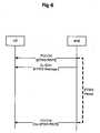
- Figure 6shows a warning message transmission process according to a second embodiment of the present invention.
- a terminalmay receive or monitor a physical downlink control channel (PDCCH) for a certain time window/time period allocated for a transmission of the warning (ETWS) message according to the received scheduling information.
- the terminalmay receive a particular radio network temporary identifier (RNTI) through the physical downlink control channel (PDCCH). More specifically, the terminal may periodically monitor the certain time window according to an ETWS period for a receiving of the warning (ETWS) message.
- the ETWS periodmay be a paging DRX (Discontinuous Reception) period, which set for the terminal to periodically receive a paging from a base station, or a multiple of the paging DRX period. Accordingly, if the ETWS period is same as the paging DRX period, the terminal may monitor the warning (ETWS) message based on the paging DRX period.
- the terminalmay receive the warning (ETWS) message through a downlink shared channel (DL-SCH), which corresponds to the physical downlink control channel (PDCCH), if the particular radio network temporary identifier is indicated in the physical downlink control channel during the first step. However, if the particular radio network temporary identifier is not indicated in the physical downlink control channel during the first step, the terminal may not receive the warning (ETWS) message through the downlink shared channel.
- DL-SCHdownlink shared channel
- PDCCHphysical downlink control channel
- a base stationmay retransmit the warning (ETWS) message using a HARQ (Hybrid Automatic Repeat reQuest) operation of the downlink shared channel. Therefore, if the terminal does not completely receive the warning (ETWS) message, the terminal may retry to receive the warning (ETWS) message using the HARQ operation.
- the system information and/or the warning (ETWS) messagemay be divided into a primary ETWS notification and a secondary ETWS notification. Namely, the primary ETWS notification and the secondary ETWS notification can be transmitted to the terminal at same time. Or, under a certain circumstance, the terminal may receive the secondary ETWS notification after receiving of the primary ETWS notification.
- the present inventionmay provide a method of receiving a warning message in mobile communication system, the method comprising: receiving control information related to the warning message through a first downlink control channel; and receiving the warning message based on the received control information through a second downlink control channel, wherein the warning message is an Earthquake and Tsunami Warning System (ETWS) message, the first downlink control channel is a Physical Downlink Control Channel (PDCCH), the control information includes a Radio network Temporary Identifier (RNTI), the control information includes radio resource information for the warning message is to be transmitted, the second downlink control channel is a logical channel that maps to a downlink shared channel (D-SCH), the control information includes a primary ETWS notification and a secondary ETWS notification, the primary ETWS notification is firstly received before the reception of the secondary ETWS notification, and the second downlink control channel is a downlink shared control channel received by a plurality of terminals.
- EWSEarthquake and Tsunami Warning System
- the present inventionmay provide a method of receiving a warning message in mobile communication system, the method comprising: monitoring a physical downlink control channel (PDCCH) periodically for a certain time period; receiving a specific Radio Network Temporary Identifier (RNTI) related to the warning message through the PDCCH; and receiving the warning message based on the specific RNTI through a downlink control channel, wherein the warning message is an Earthquake and Tsunami Warning System (ETWS) message, the specific RNTI is an ETWS RNTI, the downlink control channel is a logical channel that maps with a downlink shared channel (D-SCH), and the certain time period is a time period for broadcasting the warning message.
- PDCCHphysical downlink control channel
- RNTIRadio Network Temporary Identifier
- the present inventionhas an effect of efficiently receiving a warning message with a minimum delay while efficient usage of radio resource(s) is achieved.
- the present disclosuremay provide potential solutions for ETWS (Earthquake and Tsunami Warning System) in E-UTRAN.
- ETWSEarthquake and Tsunami Warning System
- UEmay not need to monitor ETWS message every time for battery saving.
- itwill be beneficial to help users receive frequent update of Earthquake and Tsunami.
- the present disclosuremay provide to have two steps to minimize UE battery power consumption.
- the eNBmay transmit a primary indication of Earthquake and Tsunami Warning to the UE.
- the eNBmay transmit a transfer/update of Earthquake and Tsunami Warning to the UE.
- the eNBmay provide the primary indication when the first warning is received. Afterwards, the eNB may prepare the second step to transmit updates of the warning. The UEs may periodically check if there is primary indication of the warning or not while performing a normal operation. If there is primary indication of the warning, the UEs move onto the second step and so receive next updates.
- the present disclosureproposes that the UE should check the warning only with minimal effort while performing a normal operation.
- the UEmust receive incoming warning messages with more effort.
- Start of the warningshould be notified as quickly as possible.
- paging message with a warning causecould be one of solutions.
- the paging messagecannot reach to the UEs in connected mode because the UEs in connected mode do not monitor the paging message.
- following solutionscan be used for connected UEs.
- a first optionis that indicating the start of the warning by changing of system information.
- the update of the warningis transmitted on a common logical channel dedicated to broadcast of the warning. If the warning begins, the system information carrying ETWS specific common channel configuration will be included in system information block (SIB). As a result, the UEs will receive change of system information for it. In this scheme, if the UEs find out that system information carrying ETWS specific common channel configuration is included in the SIB, the UEs may be notified the start of the warning. Then, the UEs may move onto the second step.
- SIBsystem information block
- a second optionis that indicating the start of the warning by using an ETWS specific RNTI on PDCCH.
- the connected UEswould frequently monitor the PDCCH with some RNTIs.
- the present disclosuremay propose to use the ETWS specific RNTI. Therefore, if UEs finds the ETWS specific RNTI on the PDCCH, the UEs may be notified the start of the warning. Then, the UEs may move onto the second step.
- the eNBmay repeat the ETWS specific RNTI on available PDCCH channels for certain duration in order to make sure that all UEs receive the ETWS specific RNTI.
- the UEmay need to check indication of the ETWS specific RNTI on the PDCCH in addition to other RNTI. In this option, the UEs should check additional RNTI. To alleviate it, the eNB may provide some periodic opportunities in which ETWS specific RNTI is allowed to be transmitted.
- the warningis notified to the UE, frequent update of Earthquake and Tsunami will be helpful for every user.
- the warningmay be provided by a multimedia messaging in E-UTRAN.
- the present disclosureproposes to implement transfer/update of the warning not on PCCH but on a common logical channel. (e.g. ETWS specific MTCH, CTCH or CCCH)
- the common logical channelis mapped to DL-SCH.
- the ETWS message on the DL-SCHmay be periodically scheduled every ETWS period.
- the ETWS periodis not UE specific but cell specific.
- the UEsmay receive DL-SCH to receive ETWS message every ETWS period.
- the ETWS messagemay include details of the warning and/or update of the warning.
- the PDCCHmay help UE to save its battery.
- the PDCCHmay indicate an ETWS RNTI.
- the eNBmay perform HARQ re-transmission for the ETWS message on the DL-SCH.
- the UEperiodically monitors the PDCCH within a time window to check if there is the ETWS RNTI. If the UE finds the ETWS RNTI, the UE receives the ETWS message on the DL-SCH. If the UE fails to find the ETWS RNTI within the time window, the UE may perform DRX and may wait until the next time window.
- the eNBmay repeat transmission of ETWS message. Further, the eNB may sometimes transmit a new ETWS message. Thus, such update information may be provided by either the ETWS message or the PDCCH.
- ETWS scheduling informationshould be provided to UE.
- the ETWS scheduling informationcan be provided by system information on a BCCH. If a paging message is used to carry the primary indication of the warning, the paging message could also provide the ETWS scheduling information only to idle UEs.
- ETWS channel configurationalso can be carried on system information on BCCH.
- the present disclosureprovides two steps (i.e., step 1: Primary indication of Earthquake and Tsunami Warning, step 2: Transfer/update of Earthquake and Tsunami Warning) for transmitting/receiving ETWS message, and proposes that the UEs receive primary indication of the warning by finding out inclusion of ETWS specific common channel configuration in SIB or by receiving ETWS specific RNTI on PDCCH, a common logical channel mapped onto DL-SCH is used to carry ETWS message, once the warning begins, the eNB provides periodic opportunities on DL-SCH to carry ETWS message and UEs monitors the periodic opportunities every ETWS period, the PDCCH associated with the DL-SCH indicates the ETWS RNTI.
- the System information on BCCH and/or paging message for primary indicationtransfers ETWS scheduling information, and the System information on BCCH carries ETWS channel configuration.
- system informationcarries the primary notification as well as the secondary notification, it may not meet the delay requirement on the primary notification. It is because a typical length of the BCCH modification period is more than the delay requirement (i.e. 4 seconds).
- the present disclosurepropose to implement this scheme because E-UTRAN will have only one delivery mechanism for the ETWS notification regardless of the type of the notification (i.e. the primary or the secondary notification), if the primary notification is carried on BCCH,. Also, if it is the case, the same level of security (i.e. the digital signature based security) can be applied to the primary notification as well as the secondary notification.
- ETWS specific BCCH modification periodcarrying ETWS messages, such as an ETWS modification period.
- the length of the ETWS modification periodmay be equal to or more than the length of the paging DRX cycle and should be less than the length of the normal BCCH modification period.
- the ETWS modification periodhas no impact on operation of normal system information blocks because delivery of the ETWS message on BCCH does not change any other system information. Only the ETWS messages on BCCH may follow the ETWS modification period.
- configuration of ETWS delivery including the length of the ETWS modification periodwill be broadcast on the other SIB than the SIB carrying ETWS messages.
- the SIB carrying the configuration of ETWS deliveryfollows the normal BCCH modification period.
- system information mentioned in present disclosuremay be divided into the Master Information Block (MIB) and a number of System Information Blocks (SIBs).
- the MIBincludes a limited number of most essential and most frequently transmitted parameters that are needed to acquire other information from the cell, and is transmitted on BCH.
- SIBs other than System Information Block Type1may be carried in System Information (SI) messages and mapping of SIBs to SI messages is flexibly configurable by scheduling Information included in System Information Block Type1.
- SI messagesare transmitted within periodically occurring time domain windows (referred to as SI-windows) using dynamic scheduling.
- the UEacquires the detailed time-domain scheduling (and other information, e.g. frequency-domain scheduling, used transport format) from decoding SI-RNTI on PDCCH.
- a single SI-RNTIis used to address System Information Block Type1 as well as all SI messages.
- the System Information Block Type1configures the SI-window length and the transmission periodicity for the SI messages.
- the System Information Block Type10may contain an ETWS primary notification and the System Information Block Type11 may contain an ETWS secondary notification. More specifically, fields included in the SIB type 10 and/or SIB type 11 may contains a parameter or value to indicate a source and type of ETWS notification, variations of the ETWS notification, a warning type of the ETWS notification, security information for the ETWS notification, and segment number of the ETWS warning message segment, etc.
- the purpose of the present disclosureis to transmit paging information (or message) to a UE in RRC_IDLE mode and/or to inform UEs in RRC_IDLE mode and UEs in RRC_CONNECTED mode about a system information change and/or about an ETWS primary notification and/or ETWS secondary notification.
- the paging informationis provided to upper layers, which in response may initiate RRC connection establishment, (e.g. to receive an incoming call).
- E-UTRANmay initiate the paging procedure by transmitting the Paging message at the UE's paging occasion.
- the E-UTRANmay also indicate a change of system information and/or provide an ETWS notification in the Paging message. Namely, if present, the indication of an ETWS primary notification and/or ETWS secondary notification may be included in some field in the paging message.
- the present inventionis described in the context of mobile communications, the present invention may also be used in any wireless communication systems using mobile devices, such as PDAs and laptop computers equipped with wireless communication capabilities (i.e. interface). Moreover, the use of certain terms to describe the present invention is not intended to limit the scope of the present invention to a certain type of wireless communication system. The present invention is also applicable to other wireless communication systems using different air interfaces and/or physical layers, for example, TDMA, CDMA, FDMA, WCDMA, OFDM, EV-DO, Wi-Max, Wi-BroTM, etc.
- the exemplary embodimentsmay be implemented as a method, apparatus or article of manufacture using standard programming and/or engineering techniques to produce software, firmware, hardware, or any combination thereof.
- article of manufacturerefers to code or logic implemented in hardware logic (e.g., an integrated circuit chip, Field Programmable Gate Array (FPGA), Application Specific Integrated Circuit (ASIC), etc.) or a computer readable medium (e.g., magnetic storage medium (e.g., hard disk drives, floppy disks, tape, etc.), optical storage (CD-ROMs, optical disks, etc.), volatile and non-volatile memory devices (e.g., EEPROMs, ROMs, PROMs, RAMs, DRAMs, SRAMs, firmware, programmable logic, etc.).
- FPGAField Programmable Gate Array
- ASICApplication Specific Integrated Circuit
- Code in the computer readable mediummay be accessed and executed by a processor.
- the code in which exemplary embodiments are implementedmay further be accessible through a transmission media or from a file server over a network.
- the article of manufacture in which the code is implementedmay comprise a transmission media, such as a network transmission line, wireless transmission media, signals propagating through space, radio waves, infrared signals, etc.
- a transmission mediasuch as a network transmission line, wireless transmission media, signals propagating through space, radio waves, infrared signals, etc.
Landscapes
- Engineering & Computer Science (AREA)
- Computer Networks & Wireless Communication (AREA)
- Signal Processing (AREA)
- Business, Economics & Management (AREA)
- Health & Medical Sciences (AREA)
- Emergency Management (AREA)
- Environmental & Geological Engineering (AREA)
- Public Health (AREA)
- Mobile Radio Communication Systems (AREA)
Description
- The present invention relates to a method of receiving a disaster warning message (or any warning message) in wireless communication system. More particularly, a terminal (UE) set or establish a control logical channel broadcasting a warning message, periodically monitors a warning message broadcasting time period, receives a Radio Network Temporary Identifier (RNTI) through a Physical Downlink Control Channel (PDCCH) during the warning message broadcasting time period, and receives the warning message through a control logical channel that maps with a downlink shared channel.
Figure 1 shows an exemplary network structure of an Evolved Universal Mobile Telecommunications System (E-UMTS) as a mobile communication system to which a related art and the present invention are applied. The E-UMTS system is a system that has evolved from the UMTS system, and its standardization work is currently being performed by the 3GPP standards organization. The E-UMTS system can also be referred to as a Long-Term Evolution (LTE) system.- The E-UMTS network can roughly be divided into an Evolved Universal Terrestrial Radio Access Network (E-UTRAN) and a Core Network (CN). The E-UTRAN generally comprises a terminal (i.e., User Equipment (UE)), a base station (i.e., eNode B), and an Access Gateway (AG) that is located at an end of the E-UMTS network and connects with one or more external networks. The AG may be divided into a part for processing user traffic and a part for handling control traffic. Here, an AG for processing new user traffic and an AG for processing control traffic can be communicated with each other by using a new interface. One eNode B may have one or more cells. An interface for transmitting the user traffic or the control traffic may be used among the eNode Bs. The CN may comprise an AG, nodes for user registration of other UEs, and the like. An interface may be used to distinguish the E-UTRAN and the CN from each other.
- Radio interface protocol layers between the terminal and the network can be divided into a first layer (L1), a second layer (L2) and a third layer (L3) based on three lower layers of an Open System Interconnection (OSI) standard model widely known in communications systems. A physical layer belonging to the first layer provides an information transfer service using a physical channel. A Radio Resource Control (RRC) layer located at the lowest portion of the third layer controls radio resources between the terminal and the network. For this purpose, the RRC layer allows RRC messages to be exchanged between the terminal and the network.
Fig. 2 shows radio interface protocol architecture between a terminal and E-UTRAN based on 3GPP radio access network standards. The radio interface protocol inFig. 2 have horizontal layers comprising a physical layer, a data link layer and a network layer, and has vertical planes comprising a user plane for transmitting user traffic and a control plane for transmitting control signals. The protocol layers inFig. 2 can be divided into a first layer (L1), a second layer (L2) and a third layer (L3) based on three lower layers of an Open System Interconnection (OSI) standard model widely known in communications systems. Hereinafter, each layer in the radio protocol architecture inFig. 2 will be described.- A first layer, as a physical layer, provides an information transfer service to an upper layer using a physical channel. The physical layer is connected to its upper layer, called a Medium Access Control (MAC) layer, via a transport channel. The MAC layer and the physical layer exchange data via the transport channel. Data is transferred via a physical channel between different physical layers, namely, between the physical layer of a transmitting side and the physical layer of a receiving side. The physical channel is modulated based on an Orthogonal Frequency Division Multiplexing (OFDM) technique, and utilizes time and frequency as radio resources.
- The MAC layer located at the second layer provides a service to an upper layer, called a Radio Link Control (RLC) layer, via a logical channel. The RLC layer of the second layer supports reliable data transmissions. The function of the RLC layer may be implemented as a functional block in the MAC layer. In this case, the RLC layer may not exist. A Packet Data Convergence Protocol (PDCP) layer of the second layer, in the radio protocol user plane, is used to efficiently transmit IP packets, such as IPv4 or IPv6, on a radio interface with a relatively narrow bandwidth. For this purpose, the PDCP layer reduces the size of an IP packet header which is relatively great in size and includes unnecessary control information, namely, a function called header compression is performed.
- A Radio Resource Control (RRC) layer located at the lowest portion of the third layer is only defined in the control plane. The RRC layer controls logical channels, transport channels and physical channels in relation to establishment, re-configuration and release of Radio Bearers (RBs). Here, the RB signifies a service provided by the second layer for data transmissions between the terminal and the E-UTRAN. If an RRC connection is established between the RRC layer of the terminal and the RRC layer of the radio network, the terminal is in the RRC connected mode. Otherwise, the terminal is in an RRC idle mode.
- A Non-Access Stratum (NAS) layer located at an upper portion of the RRC layer performs functions, such as session management, mobility management and the like.
- One cell constructing an eNB is set to one of bandwidths of 1.25 MHz, 2.5 MHz, 5 MHz, 10 MHz, 20 MHz and the like, so as to provide downlink or uplink transmission services to multiple terminals. Here, different cells may be set to provide different bandwidths.
- Downlink transport channels for transmitting data from a network to a terminal may comprise a Broadcast Channel (BCH) for transmitting system information, a Paging Channel (PCH) for transmitting paging messages and a downlink Shared Channel (SCH) for transmitting other user traffic or control messages. Traffic or control messages of a downlink point-to-multipoint service (multicast or broadcast service) may be transmitted either via a downlink SCH, or via a separate downlink Multicast Channel (MCH). In addition, uplink transport channels for transmitting data from a terminal to a network may comprise a Random Access Channel (RACH) for transmitting an initial control message and an uplink Shared Channel (SCH) for transmitting user traffic or control messages.
- Logical channels which are located at an upper portion of transport channels and mapped to the transport channels include a Broadcast Control Channel (BCCH), a Paging Control Channel (PCCH), a Common Control Channel (CCCH), a MBMS point-to-multipoint Control Channel / Multicast Control Channel (MCCH), a MBMS point-to-multipoint Traffic Channel / Multicast Traffic Channel (MTCH), and the like.
Fig. 3 shows a transmission on a control channel according to the related art.- A physical channel is composed of multiple sub-frames arranged on a time axis and multiple sub-carriers arranged on a frequency axis. Here, a single sub-frame includes a plurality of symbols on the time axis. One sub-frame is composed of a plurality of resource blocks, each of which includes a plurality of symbols and a plurality of sub-carriers. Also, each sub-frame can use particular sub-carriers of particular symbols (e.g., a first symbol) at the corresponding sub-frame for a Physical Downlink Control Channel (PDCCH), namely, a L1/L2 control channel. One sub-frame is time duration of 0.5 ms. A Transmission Time Interval (TTI) as a unit time for which data is transmitted is 1 ms corresponding to two sub-frames.
FIG. 4 is a block diagram of a network structure for a cell broadcast service. As illustrated inFIG. 4 , CBS messages originate in a plurality of cell broadcast entities (hereinafter abbreviated CBEs) connected to a cell broadcast center (hereinafter abbreviated CBC). The CBE separates the CBS message into a plurality of pages. The CBC is one node of a core network that performs a scheduling function by managing the CBS message. lu-BC is an interface defined between the CBC and the RNC using a service area broadcast protocol (hereinafter abbreviated SABP). The CBC can give the RNC a broadcast order for a new message or enable a previous broadcast message to be modified or terminated using the SABP. The RNC performs a scheduling function for a CBS message delivered by the CBC and a broadcasting function to transmit the message to a specific cell using a BMC protocol. The RNC has a broadcast/multicast inter-working function (hereinafter abbreviated BMC-IWF) above a BMC layer to perform an interpreting function for a message and information delivered from the CBC. The UE receives a CBS message broadcast by the UTRAN. Examples of BMC messages used in the BMC protocol are a CBS message delivering user information, a schedule message facilitating reception of a CBS message by a UE and a CBS41 message delivering a short message delivered from an ANS141 network. All the messages are transmitted from the UTRAN to the UE in uni-direction through a logical channel such as CTCH (Common Traffic Channel). The UE can reduce its battery consumption by performing discontinuous reception (hereinafter abbreviated DRX) using information in the schedule message transmitted by the UTRAN through CTCH (Common Traffic Channel).- In a conventional Cell Broadcast Service (CBS) scheme, scheduling information related to a warning message is transmitted through a Common Traffic Channel (CTCH). Therefore, in a related art, this cause a great drawback that a terminal cannot promptly or quickly receive scheduling information of the warning message since the terminal usually receives a traffic channel after receiving of the control channel first. Further, in general, the CTCH is mapped with a Forward Access Channel (FACH), which is statically or persistently scheduled transport channel. Therefore, using of the CTCH channel to transmit the scheduling information of the warning message may cause a great drawback of inefficient usage of a radio resource(s).
- Document
US 2005/037728 A1 may be construed to disclose a method and an apparatus in a wireless communication system for communicating contents of a broadcast message. A wireless portable communication device receives an emergency status indicator associated with the broadcast message from a base station. Upon determining the broadcast message is an emergency message, the contents of the broadcast message are immediately communicated. - Document
WO 98/05176 A2 - Document 3GPP TS 22.168 V1.2.1 may be construed to disclose the stage one description of the Earthquake and Tsunami Warning System (ETWS) Requirements. Stage one is the set of requirements seen primarily from the users' and service providers' points of view. The document includes information applicable to network operators, service providers, terminal and network manufacturers, in case of deployment of ETWS. ETWS deployment depends on operator decision or national regulations. Further, the document contains the core requirements for the Earthquake and Tsunami Warning System, which are sufficient to provide a complete service, and regional requirements for Earthquake and Tsunami Warning System.
- Document "Transmission of dynamic system information", 3GPP draft R2-075559 may be construed to disclose a scheduling method for transmission of dynamic part of the system information involving the following proposals: Proposal 1: It is proposed that starting points for system information windows are predefined by the frame number in order to minimize the amount of information that UE needs in order to "understand" how to acquire dynamic part of System Information. Therefore, start of the window is at subframe #5 within frame N*8; Proposal 2: A common SI-RNTI is used for all the SU's transmitted; Proposal 3: In order for the UE to understand what information should be soft combined, different SUs are identified by different HARQ process ID. Current PDCCH format includes already (HARQ related information) such a process ID that can be reused for the case of BCCH transmission; Proposal 4: The number of redundancy versions to use (RV=4) should follow normal DL-SCH physical layer processing given the number of bits; Proposal 5: introduce "end-of-system-information" indicator on the PDCCH, ESI-RNTI in order for UE to stop monitoring PDCCH once UE has received all the available information.
- The embodiments and/or examples disclosed in the following description which are not covered by the appended claims are considered as not being part of the invention.
- According to the invention, there are provided a method, a computer-readable medium and an apparatus according to the independent claims. Developments are set forth in the dependent claims.
Figure 1 shows an exemplary network structure of an Evolved Universal Terrestrial Radio Access Network (E-UTRAN) as a mobile communication system to which a related art and the present invention are applied;Figure 2 shows a radio interface protocol architecture between a terminal and a Evolved UMTS Terrestrial Radio Access Network (E-UTRAN) based on 3GPP radio access network standards;Figure 3 shows an exemplary view of a related art physical channel structure for control channel transmission;Figure 4 shows an exemplary block diagram of a network structure for a cell broadcast service;Figure 5 shows a warning message transmission process according to a first embodiment of the present invention; andFigure 6 shows a warning message transmission process according to a second embodiment of the present invention.- One aspect of the present invention is the recognition by the present inventors regarding the problems and drawbacks of the related art described above and explained in more detail hereafter. Based upon such recognition, the features of the present invention have been developed.
- The present invention may be embodied in a 3GPP communication technology, in particular, in the Universal Mobile Telecommunications System (UMTS) system, a communication apparatus and method thereof. However, the present invention may also be applied to all wired/wireless communications to which the technical scope of the present invention can be applied.
- Hereinafter, description of structures and operations of the preferred embodiments according to the present invention will be given with reference to the accompanying drawings.
Figure 5 shows a warning message transmission process according to a first embodiment of the present invention. In the present invention, a warning message (which will be referred as ETWS (Earthquake and Tsunami Warning System) message hereafter) may be transmitted through a logical channel broadcasting a control message to a plurality of terminals and a transport channel (i.e., Downlink Shared Channel; DL-SCH) mapping with the logical channel.- As illustrated in
Figure 5 , in a first step, a terminal (UE) may receive system information through a logical channel such as a Broadcast Control Channel (BCCH). If the received system information contains scheduling information (or setup information or any other information related to the warning (ETWS) message) of the warning (ETWS) message, the terminal may further process a next step to receive the warning (ETWS) message. However, if the received system information does not contain the scheduling information of the warning (ETWS) message, the terminal may not further process a next step. Here, the scheduling information may include information about a time period that the warning (ETWS) message is transmitted. Namely, the scheduling information may include specific time information about when the warning (ETWS) message is transmitted. - In a second step, the terminal may receive or monitor a physical downlink control channel (PDCCH) for a certain time window/time period allocated for a transmission of the warning (ETWS) message according to the received scheduling information. Here, the terminal may receive a particular radio network temporary identifier (RNTI) through the physical downlink control channel (PDCCH).
- In a third step, the terminal may receive the warning (ETWS) message through a downlink shared channel (DL-SCH), which corresponds to the physical downlink control channel (PDCCH), if the particular radio network temporary identifier (i.e., ETWS RNTI) is indicated in the physical downlink control channel during the second step. However, if the particular radio network temporary identifier is not indicated in the physical downlink control channel during the second step, the terminal may not receive the warning (ETWS) message through the downlink shared channel.
- Here, a warning (ETWS) message is transmitted or received through a transport channel such as a downlink shared channel (DL-SCH), which is mapped with a logical control channel (i.e., shared logical channel) that is used for a plurality of terminals to receives control information commonly. Accordingly, the warning (ETWS) message may be transmitted through the logical control channel and the downlink shared channel by a base station. Also, the terminal may receive the warning (ETWS) message the logical control channel and the downlink shared channel.
- Here, a base station (eNB) may retransmit the warning (ETWS) message using a HARQ (Hybrid Automatic Repeat reQuest) operation of the downlink shared channel. Therefore, if the terminal does not completely receive the warning (ETWS) message, the terminal may retry to receive the warning (ETWS) message using the HARQ operation. The system information and/or the warning (ETWS) message may be divided into a primary ETWS notification and a secondary ETWS notification. Namely, the primary ETWS notification and the secondary ETWS notification can be transmitted to the terminal at same time. Or, under a certain circumstance, the terminal may receive the secondary ETWS notification after receiving of the primary ETWS notification.
Figure 6 shows a warning message transmission process according to a second embodiment of the present invention.- As illustrated in
Figure 6 , in a first step, a terminal may receive or monitor a physical downlink control channel (PDCCH) for a certain time window/time period allocated for a transmission of the warning (ETWS) message according to the received scheduling information. Here, the terminal may receive a particular radio network temporary identifier (RNTI) through the physical downlink control channel (PDCCH). More specifically, the terminal may periodically monitor the certain time window according to an ETWS period for a receiving of the warning (ETWS) message. The ETWS period may be a paging DRX (Discontinuous Reception) period, which set for the terminal to periodically receive a paging from a base station, or a multiple of the paging DRX period. Accordingly, if the ETWS period is same as the paging DRX period, the terminal may monitor the warning (ETWS) message based on the paging DRX period. - In a second step, the terminal may receive the warning (ETWS) message through a downlink shared channel (DL-SCH), which corresponds to the physical downlink control channel (PDCCH), if the particular radio network temporary identifier is indicated in the physical downlink control channel during the first step. However, if the particular radio network temporary identifier is not indicated in the physical downlink control channel during the first step, the terminal may not receive the warning (ETWS) message through the downlink shared channel.
- Here, a base station (eNB) may retransmit the warning (ETWS) message using a HARQ (Hybrid Automatic Repeat reQuest) operation of the downlink shared channel. Therefore, if the terminal does not completely receive the warning (ETWS) message, the terminal may retry to receive the warning (ETWS) message using the HARQ operation. The system information and/or the warning (ETWS) message may be divided into a primary ETWS notification and a secondary ETWS notification. Namely, the primary ETWS notification and the secondary ETWS notification can be transmitted to the terminal at same time. Or, under a certain circumstance, the terminal may receive the secondary ETWS notification after receiving of the primary ETWS notification.
- The present invention may provide a method of receiving a warning message in mobile communication system, the method comprising: receiving control information related to the warning message through a first downlink control channel; and receiving the warning message based on the received control information through a second downlink control channel, wherein the warning message is an Earthquake and Tsunami Warning System (ETWS) message, the first downlink control channel is a Physical Downlink Control Channel (PDCCH), the control information includes a Radio network Temporary Identifier (RNTI), the control information includes radio resource information for the warning message is to be transmitted, the second downlink control channel is a logical channel that maps to a downlink shared channel (D-SCH), the control information includes a primary ETWS notification and a secondary ETWS notification, the primary ETWS notification is firstly received before the reception of the secondary ETWS notification, and the second downlink control channel is a downlink shared control channel received by a plurality of terminals.
- It can be also said that the present invention may provide a method of receiving a warning message in mobile communication system, the method comprising: monitoring a physical downlink control channel (PDCCH) periodically for a certain time period; receiving a specific Radio Network Temporary Identifier (RNTI) related to the warning message through the PDCCH; and receiving the warning message based on the specific RNTI through a downlink control channel, wherein the warning message is an Earthquake and Tsunami Warning System (ETWS) message, the specific RNTI is an ETWS RNTI, the downlink control channel is a logical channel that maps with a downlink shared channel (D-SCH), and the certain time period is a time period for broadcasting the warning message.
- Namely, the present invention has an effect of efficiently receiving a warning message with a minimum delay while efficient usage of radio resource(s) is achieved.
- The present disclosure may provide potential solutions for ETWS (Earthquake and Tsunami Warning System) in E-UTRAN. Usually, usages of ETWS messages are very rare. Thus, UE may not need to monitor ETWS message every time for battery saving. However, once they take place, it will be beneficial to help users receive frequent update of Earthquake and Tsunami. For this reason above, the present disclosure may provide to have two steps to minimize UE battery power consumption. As for the first step, the eNB may transmit a primary indication of Earthquake and Tsunami Warning to the UE. Then, for the second step, the eNB may transmit a transfer/update of Earthquake and Tsunami Warning to the UE. Specifically, the eNB may provide the primary indication when the first warning is received. Afterwards, the eNB may prepare the second step to transmit updates of the warning. The UEs may periodically check if there is primary indication of the warning or not while performing a normal operation. If there is primary indication of the warning, the UEs move onto the second step and so receive next updates. Here, during the first step, the present disclosure proposes that the UE should check the warning only with minimal effort while performing a normal operation. On the other hand, during the second step, the UE must receive incoming warning messages with more effort.
- More detailed description of the first step will be given as following. Start of the warning should be notified as quickly as possible. When UE is idle, paging message with a warning cause could be one of solutions. However, in most of cases, the paging message cannot reach to the UEs in connected mode because the UEs in connected mode do not monitor the paging message. Thus, following solutions can be used for connected UEs.
- A first option is that indicating the start of the warning by changing of system information. The update of the warning is transmitted on a common logical channel dedicated to broadcast of the warning. If the warning begins, the system information carrying ETWS specific common channel configuration will be included in system information block (SIB). As a result, the UEs will receive change of system information for it. In this scheme, if the UEs find out that system information carrying ETWS specific common channel configuration is included in the SIB, the UEs may be notified the start of the warning. Then, the UEs may move onto the second step.
- A second option is that indicating the start of the warning by using an ETWS specific RNTI on PDCCH. In most case, the connected UEs would frequently monitor the PDCCH with some RNTIs. Thus, the present disclosure may propose to use the ETWS specific RNTI. Therefore, if UEs finds the ETWS specific RNTI on the PDCCH, the UEs may be notified the start of the warning. Then, the UEs may move onto the second step. Here, when the warning starts, the eNB may repeat the ETWS specific RNTI on available PDCCH channels for certain duration in order to make sure that all UEs receive the ETWS specific RNTI. On the other hand, whenever the UE reads the PDCCH, the UE may need to check indication of the ETWS specific RNTI on the PDCCH in addition to other RNTI. In this option, the UEs should check additional RNTI. To alleviate it, the eNB may provide some periodic opportunities in which ETWS specific RNTI is allowed to be transmitted.
- More detailed description of the second step will be given as following. Once the warning is notified to the UE, frequent update of Earthquake and Tsunami will be helpful for every user. In case that paging message is used for the first step, after the warning begins, several paging messages would cause overload. Moreover, the warning may be provided by a multimedia messaging in E-UTRAN. Thus, the present disclosure proposes to implement transfer/update of the warning not on PCCH but on a common logical channel. (e.g. ETWS specific MTCH, CTCH or CCCH) Here, the common logical channel is mapped to DL-SCH.
- The ETWS message on the DL-SCH may be periodically scheduled every ETWS period. Here, the ETWS period is not UE specific but cell specific. After receiving primary indication of the warning, the UEs may receive DL-SCH to receive ETWS message every ETWS period. The ETWS message may include details of the warning and/or update of the warning.
- In addition, the PDCCH may help UE to save its battery. If the ETWS message is transmitted on DL-SCH, the PDCCH may indicate an ETWS RNTI. The eNB may perform HARQ re-transmission for the ETWS message on the DL-SCH. The UE periodically monitors the PDCCH within a time window to check if there is the ETWS RNTI. If the UE finds the ETWS RNTI, the UE receives the ETWS message on the DL-SCH. If the UE fails to find the ETWS RNTI within the time window, the UE may perform DRX and may wait until the next time window.
- Apart from the HARQ re-transmission on the DL-SCH, the eNB may repeat transmission of ETWS message. Further, the eNB may sometimes transmit a new ETWS message. Thus, such update information may be provided by either the ETWS message or the PDCCH.
- ETWS scheduling information should be provided to UE. The ETWS scheduling information can be provided by system information on a BCCH. If a paging message is used to carry the primary indication of the warning, the paging message could also provide the ETWS scheduling information only to idle UEs. Moreover, ETWS channel configuration also can be carried on system information on BCCH.
- In summary, the present disclosure provides two steps (i.e., step 1: Primary indication of Earthquake and Tsunami Warning, step 2: Transfer/update of Earthquake and Tsunami Warning) for transmitting/receiving ETWS message, and proposes that the UEs receive primary indication of the warning by finding out inclusion of ETWS specific common channel configuration in SIB or by receiving ETWS specific RNTI on PDCCH, a common logical channel mapped onto DL-SCH is used to carry ETWS message, once the warning begins, the eNB provides periodic opportunities on DL-SCH to carry ETWS message and UEs monitors the periodic opportunities every ETWS period, the PDCCH associated with the DL-SCH indicates the ETWS RNTI. The System information on BCCH and/or paging message for primary indication transfers ETWS scheduling information, and the System information on BCCH carries ETWS channel configuration.
- In some case, if system information carries the primary notification as well as the secondary notification, it may not meet the delay requirement on the primary notification. It is because a typical length of the BCCH modification period is more than the delay requirement (i.e. 4 seconds). However, the present disclosure propose to implement this scheme because E-UTRAN will have only one delivery mechanism for the ETWS notification regardless of the type of the notification (i.e. the primary or the secondary notification), if the primary notification is carried on BCCH,. Also, if it is the case, the same level of security (i.e. the digital signature based security) can be applied to the primary notification as well as the secondary notification.
- One possibility to meet the delay requirement of the primary notification on BCCH is to have an ETWS specific BCCH modification period carrying ETWS messages, such as an ETWS modification period. The length of the ETWS modification period may be equal to or more than the length of the paging DRX cycle and should be less than the length of the normal BCCH modification period. Here, the ETWS modification period has no impact on operation of normal system information blocks because delivery of the ETWS message on BCCH does not change any other system information. Only the ETWS messages on BCCH may follow the ETWS modification period. It should be noted that configuration of ETWS delivery including the length of the ETWS modification period will be broadcast on the other SIB than the SIB carrying ETWS messages. The SIB carrying the configuration of ETWS delivery follows the normal BCCH modification period.
- It should be noted that system information mentioned in present disclosure may be divided into the Master Information Block (MIB) and a number of System Information Blocks (SIBs). The MIB includes a limited number of most essential and most frequently transmitted parameters that are needed to acquire other information from the cell, and is transmitted on BCH. SIBs other than System Information Block Type1 may be carried in System Information (SI) messages and mapping of SIBs to SI messages is flexibly configurable by scheduling Information included in System Information Block Type1. The SI messages are transmitted within periodically occurring time domain windows (referred to as SI-windows) using dynamic scheduling. The UE acquires the detailed time-domain scheduling (and other information, e.g. frequency-domain scheduling, used transport format) from decoding SI-RNTI on PDCCH. A single SI-RNTI is used to address System Information Block Type1 as well as all SI messages. The System Information Block Type1 configures the SI-window length and the transmission periodicity for the SI messages. The System Information Block Type10 may contain an ETWS primary notification and the System Information Block Type11 may contain an ETWS secondary notification. More specifically, fields included in the SIB type 10 and/or SIB type 11 may contains a parameter or value to indicate a source and type of ETWS notification, variations of the ETWS notification, a warning type of the ETWS notification, security information for the ETWS notification, and segment number of the ETWS warning message segment, etc.
- The purpose of the present disclosure is to transmit paging information (or message) to a UE in RRC_IDLE mode and/or to inform UEs in RRC_IDLE mode and UEs in RRC_CONNECTED mode about a system information change and/or about an ETWS primary notification and/or ETWS secondary notification. The paging information is provided to upper layers, which in response may initiate RRC connection establishment, (e.g. to receive an incoming call). E-UTRAN may initiate the paging procedure by transmitting the Paging message at the UE's paging occasion. The E-UTRAN may also indicate a change of system information and/or provide an ETWS notification in the Paging message. Namely, if present, the indication of an ETWS primary notification and/or ETWS secondary notification may be included in some field in the paging message.
- Although the present invention is described in the context of mobile communications, the present invention may also be used in any wireless communication systems using mobile devices, such as PDAs and laptop computers equipped with wireless communication capabilities (i.e. interface). Moreover, the use of certain terms to describe the present invention is not intended to limit the scope of the present invention to a certain type of wireless communication system. The present invention is also applicable to other wireless communication systems using different air interfaces and/or physical layers, for example, TDMA, CDMA, FDMA, WCDMA, OFDM, EV-DO, Wi-Max, Wi-Bro™, etc.
- The exemplary embodiments may be implemented as a method, apparatus or article of manufacture using standard programming and/or engineering techniques to produce software, firmware, hardware, or any combination thereof. The term "article of manufacture" as used herein refers to code or logic implemented in hardware logic (e.g., an integrated circuit chip, Field Programmable Gate Array (FPGA), Application Specific Integrated Circuit (ASIC), etc.) or a computer readable medium (e.g., magnetic storage medium (e.g., hard disk drives, floppy disks, tape, etc.), optical storage (CD-ROMs, optical disks, etc.), volatile and non-volatile memory devices (e.g., EEPROMs, ROMs, PROMs, RAMs, DRAMs, SRAMs, firmware, programmable logic, etc.).
- Code in the computer readable medium may be accessed and executed by a processor. The code in which exemplary embodiments are implemented may further be accessible through a transmission media or from a file server over a network. In such cases, the article of manufacture in which the code is implemented may comprise a transmission media, such as a network transmission line, wireless transmission media, signals propagating through space, radio waves, infrared signals, etc. Of course, those skilled in the art will recognize that many modifications may be made to this configuration without departing from the scope of the present invention, and that the article of manufacture may comprise any information bearing medium known in the art.
Claims (6)
- A method of receiving a warning message for a mobile communication system, wherein the warning message is an Earthquake and Tsunami Warning System, ETWS, message, the method comprising:monitoring a physical downlink control channel, PDCCH, periodically for a certain time period;receiving a single System Information-Radio Network Temporary Identifier, SI-RNTI, related to the warning message through the PDCCH;decoding the received single SI-RNTI on the PDCCH;receiving system information, SI, wherein the single SI-RNTI is used to address System Information Block, SIB, type 1, as well as all SI messages; andreceiving the warning message based on the received system information;wherein a primary ETWS notification is contained in a SIB type 10 and a secondary ETWS notification is contained in a SIB type 11.
- The method of claim 1, wherein the certain time period is a time period for broadcasting the warning message.
- The method of claim 1, wherein the primary ETWS notification is firstly received before a reception of the secondary ETWS notification.
- The method of claim 1, wherein the SI is received within periodically occurring time domain windows.
- A computer-readable medium comprising code portions which, when executed on a processor, configure the processor to perform all steps of a method according to any one of the preceding method claims.
- An apparatus configured to perform all steps of a method according to any one of claims 1 to 4.
Applications Claiming Priority (4)
| Application Number | Priority Date | Filing Date | Title |
|---|---|---|---|
| US3768108P | 2008-03-18 | 2008-03-18 | |
| US3803508P | 2008-03-19 | 2008-03-19 | |
| US7374808P | 2008-06-18 | 2008-06-18 | |
| KR1020090022685AKR101540479B1 (en) | 2008-03-18 | 2009-03-17 | Method of receiving a disaster warning message in mobile communication system |
Publications (3)
| Publication Number | Publication Date |
|---|---|
| EP2104381A2 EP2104381A2 (en) | 2009-09-23 |
| EP2104381A3 EP2104381A3 (en) | 2010-10-06 |
| EP2104381B1true EP2104381B1 (en) | 2018-10-10 |
Family
ID=40983559
Family Applications (1)
| Application Number | Title | Priority Date | Filing Date |
|---|---|---|---|
| EP09003898.5AActiveEP2104381B1 (en) | 2008-03-18 | 2009-03-18 | Method and apparatuses of receiving a disaster warning message using a system information radio network temporary identifier SI-RNTI |
Country Status (3)
| Country | Link |
|---|---|
| US (1) | US8229390B2 (en) |
| EP (1) | EP2104381B1 (en) |
| WO (1) | WO2009116795A2 (en) |
Families Citing this family (27)
| Publication number | Priority date | Publication date | Assignee | Title |
|---|---|---|---|---|
| US8599802B2 (en)* | 2008-03-14 | 2013-12-03 | Interdigital Patent Holdings, Inc. | Method and apparatus to deliver public warning messages |
| EP2107770B1 (en) | 2008-03-18 | 2017-07-05 | LG Electronics Inc. | Method and apparatus of receiving a disaster warning message using a paging message in mobile communication system |
| CA2728731C (en) | 2008-06-20 | 2017-08-29 | Interdigital Patent Holdings, Inc. | Emergency information in system information broadcast |
| CN101640574B (en)* | 2008-07-30 | 2011-07-20 | 中兴通讯股份有限公司 | Earthquake and tsunami warning system and method for transmitting primary notification |
| CN101651850B (en)* | 2008-08-13 | 2012-05-23 | 中兴通讯股份有限公司 | Method and system for transmitting main notification message of earthquake and tsunami early warning system |
| US20110002250A1 (en)* | 2008-10-27 | 2011-01-06 | Interdigital Patent Holdings, Inc. | Method and apparatus for reducing battery consumption in a wtru upon etws notification |
| CN101483833B (en)* | 2009-02-06 | 2011-06-22 | 中兴通讯股份有限公司 | Method and apparatus for receiving urgent broadcast message |
| CN101998279B (en)* | 2009-08-14 | 2013-03-27 | 中国移动通信集团公司 | Method and device for sending multicast control channel change notice |
| US10756335B2 (en) | 2009-09-29 | 2020-08-25 | George E. Mayer | Mixture of basic lead sulfates |
| US8868743B2 (en) | 2010-04-30 | 2014-10-21 | Sharp Kabushiki Kaisha | Modified access classes for machine type communication (MTC) devices during emergencies |
| US8837443B2 (en) | 2010-08-13 | 2014-09-16 | Sharp Kabushiki Kaisha | Reducing congestion in wireless communication networks |
| US9872272B2 (en) | 2010-10-01 | 2018-01-16 | Mitsubishi Electric Corporation | Communication system for reducing congestion |
| US20130012154A1 (en)* | 2011-07-08 | 2013-01-10 | Shortcode7 LLC | Alert system and method |
| KR101962245B1 (en) | 2011-09-23 | 2019-03-27 | 삼성전자 주식회사 | Method and apparatus for accessing of narrowband terminal to a wireless communication system supporting both wideband terminal and narrowband terminal |
| US8467813B2 (en)* | 2011-11-01 | 2013-06-18 | Mediatek Inc. | Method for monitoring a paging message without paging lost and communication apparatuses utilizing the same |
| JP6093023B2 (en)* | 2012-11-06 | 2017-03-08 | テレフオンアクチーボラゲット エルエム エリクソン(パブル) | Public alarm system display to users in connected mode |
| CN102984663B (en)* | 2012-12-26 | 2015-04-29 | 北京久华信信息技术有限公司 | Method for realizing group calling talk right notice for radio communication system |
| US10492021B2 (en) | 2013-05-20 | 2019-11-26 | Telefonaktiebolaget Lm Ericsson (Publ) | Methods, wireless communication networks and network nodes for recovering a public warning system |
| CN105636203B (en)* | 2014-11-07 | 2019-07-02 | 上海诺基亚贝尔股份有限公司 | Method and apparatus of the transmission for the public paging message of MTC UE |
| US10271182B2 (en) | 2015-07-29 | 2019-04-23 | Blackberry Limited | Enhanced public warning system to provide rich content |
| WO2017026806A1 (en)* | 2015-08-13 | 2017-02-16 | Lg Electronics Inc. | Method and apparatus for notifying si update, eab update and pws message in wireless communication system |
| US10326544B2 (en)* | 2015-09-22 | 2019-06-18 | Blackberry Limited | Receiving public warning system data |
| CN107426783B (en)* | 2016-05-23 | 2020-01-14 | 北京佰才邦技术有限公司 | System message transmission method and device, user terminal and network equipment |
| CN107623937B (en) | 2016-07-15 | 2021-04-16 | 夏普株式会社 | Method, base station and user equipment for sending and receiving system messages |
| US11622327B2 (en) | 2016-08-30 | 2023-04-04 | Microsoft Technology Licensing, Llc | Adaptive reception of cell broadcast service |
| CN108124245B (en)* | 2016-11-25 | 2021-05-14 | 北京小米移动软件有限公司 | Processing method, generating method and device for paging signaling message |
| WO2021159280A1 (en)* | 2020-02-11 | 2021-08-19 | 华为技术有限公司 | Communication method and apparatus |
Family Cites Families (30)
| Publication number | Priority date | Publication date | Assignee | Title |
|---|---|---|---|---|
| US227224A (en)* | 1880-05-04 | Fork-guard | ||
| US170467A (en)* | 1875-11-30 | Improvement in presses | ||
| US193394A (en)* | 1877-07-24 | Improvement in sand-pump reels | ||
| US6039624A (en) | 1996-07-29 | 2000-03-21 | At&T Wireless Services Inc. | Method for allocating a mobile station TMSI |
| US6867688B2 (en)* | 1999-06-11 | 2005-03-15 | Safety Through Cellular, Inc. | Apparatus and method for providing weather and other alerts |
| JP4002204B2 (en)* | 2002-04-09 | 2007-10-31 | 三星電子株式会社 | Control information transmission apparatus and method for multimedia broadcast / multicast service in mobile communication system |
| US20050037728A1 (en)* | 2003-08-13 | 2005-02-17 | Binzel Charles P. | Emergency broadcast message in a wireless communication device |
| US7689256B2 (en)* | 2003-11-10 | 2010-03-30 | Research In Motion Limited | Methods and apparatus for limiting communication capabilities in mobile communication devices |
| KR100595644B1 (en)* | 2004-01-09 | 2006-07-03 | 엘지전자 주식회사 | How to Receive Notification Indicator for Point-to-Multipoint Service in Mobile Communication System |
| EP1672942A1 (en)* | 2004-12-20 | 2006-06-21 | Alcatel | Transmission of information in a limited geographical area |
| KR100790093B1 (en)* | 2005-01-27 | 2007-12-31 | 삼성전자주식회사 | Method and device for receiving terminal information by determining validity of system information in a network sharing system |
| JP4513974B2 (en)* | 2005-06-27 | 2010-07-28 | 日本電気株式会社 | Wireless communication network that broadcasts high-priority information, method for changing the same, and wireless communication network design tool |
| EP1753251B1 (en) | 2005-08-10 | 2010-12-29 | Alcatel Lucent | Method of transmitting urgent alarm messages to mobile terminals being located in cells of a mobile communication network and a correponding network controller |
| DE102005050416B3 (en) | 2005-10-19 | 2007-04-19 | Siemens Ag | A method for issuing alarm messages to subscriber terminals of a radio communication system |
| KR100717677B1 (en) | 2005-11-01 | 2007-05-11 | 주식회사 엘지텔레콤 | Emergency alert system and method to notify of dangerous situations |
| US7676234B2 (en)* | 2005-11-23 | 2010-03-09 | Research In Motion Limited | Routing of a short message originated by a mobile device |
| KR20070111117A (en) | 2006-05-17 | 2007-11-21 | 에스케이 텔레콤주식회사 | Facility monitoring system and method using wired / wireless network |
| IL176275A0 (en)* | 2006-06-13 | 2007-05-15 | Celltick Technologies Ltd | Cellular emergency notification service |
| US8295243B2 (en)* | 2006-08-21 | 2012-10-23 | Qualcomm Incorporated | Method and apparatus for random access in an orthogonal multiple-access communication system |
| US8761713B2 (en)* | 2007-02-02 | 2014-06-24 | Qualcomm Incorporated | Method and apparatus for emergency broadcast using an emergency broadcast-multicast service |
| US8169957B2 (en)* | 2007-02-05 | 2012-05-01 | Qualcomm Incorporated | Flexible DTX and DRX in a wireless communication system |
| US20100183031A1 (en)* | 2007-06-26 | 2010-07-22 | Nokia Corporation | Apparatus, Method and Computer Program Product Providing Distribution of Segmented System Information |
| KR101206387B1 (en)* | 2007-07-05 | 2012-11-29 | 미쓰비시덴키 가부시키가이샤 | Mobile communication system |
| KR101066350B1 (en)* | 2007-07-20 | 2011-09-20 | 후지쯔 가부시끼가이샤 | Emergency call number information acquisition system |
| US8649795B2 (en)* | 2007-09-05 | 2014-02-11 | Blackberry Limited | Multicast/broadcast single frequency network control information transmission |
| US8077649B2 (en)* | 2007-09-13 | 2011-12-13 | Research In Motion Limited | Indication of multicast control information |
| US8300560B2 (en)* | 2007-12-28 | 2012-10-30 | Motorola Mobility Llc | Using auxiliary information to direct users of wireless devices to safety in response to emergency alert system alerts |
| US8200183B2 (en)* | 2008-03-05 | 2012-06-12 | Motorola Solutions, Inc. | Determining wireless system availability using emergency alert system messaging |
| US8599802B2 (en)* | 2008-03-14 | 2013-12-03 | Interdigital Patent Holdings, Inc. | Method and apparatus to deliver public warning messages |
| WO2009117366A1 (en)* | 2008-03-17 | 2009-09-24 | Interdigital Patent Holdings, Inc. | Public warning system for mobile devices |
- 2009
- 2009-03-18EPEP09003898.5Apatent/EP2104381B1/enactiveActive
- 2009-03-18USUS12/406,482patent/US8229390B2/enactiveActive
- 2009-03-18WOPCT/KR2009/001356patent/WO2009116795A2/enactiveApplication Filing
Non-Patent Citations (1)
| Title |
|---|
| "Transmission of dynamic system information", 3GPP DRAFT; R2-075559, 3RD GENERATION PARTNERSHIP PROJECT (3GPP), MOBILE COMPETENCE CENTRE ; 650, ROUTE DES LUCIOLES ; F-06921 SOPHIA-ANTIPOLIS CEDEX ; FRANCE, vol. RAN WG2, no. Vienna, Austria; 20071210, 10 December 2007 (2007-12-10), XP050142099* |
Also Published As
| Publication number | Publication date |
|---|---|
| WO2009116795A2 (en) | 2009-09-24 |
| WO2009116795A3 (en) | 2009-12-17 |
| US8229390B2 (en) | 2012-07-24 |
| EP2104381A3 (en) | 2010-10-06 |
| US20090253401A1 (en) | 2009-10-08 |
| EP2104381A2 (en) | 2009-09-23 |
Similar Documents
| Publication | Publication Date | Title |
|---|---|---|
| EP2104381B1 (en) | Method and apparatuses of receiving a disaster warning message using a system information radio network temporary identifier SI-RNTI | |
| US8213896B2 (en) | Method of receiving a disaster warning message using scheduling information included in system information within mobile communication system | |
| US9930508B2 (en) | Method of receiving and transmitting an earthquake and tsunami warning system (ETWS) message using a paging message in mobile communication system | |
| US8706076B2 (en) | Method of receiving a disaster warning message through a broadcast/multicast channel | |
| US7826859B2 (en) | Method for processing paging information in a wireless mobile communication system | |
| US8467329B2 (en) | Method of transmitting system information related to point-to multipoint service | |
| CN101978712B (en) | Method for receiving disaster warning message by using paging message in mobile communication system | |
| US20110019604A1 (en) | Communication method for multimedia broadcast multicast service(mbms) counting | |
| US20080273482A1 (en) | Uplink access method for receiving a point-to-multipoint service | |
| EP2206254A2 (en) | Method for transmitting data of common control channel | |
| US20110243054A1 (en) | Method of minimizing an unnecessary scheduling information reception in a wireless communication system | |
| US20110105075A1 (en) | Method of transmitting or receiving an updated warning message in mobile communication system | |
| CN101978713B (en) | Method for receiving disaster alarm message in mobile communication system |
Legal Events
| Date | Code | Title | Description |
|---|---|---|---|
| PUAI | Public reference made under article 153(3) epc to a published international application that has entered the european phase | Free format text:ORIGINAL CODE: 0009012 | |
| 17P | Request for examination filed | Effective date:20090318 | |
| AK | Designated contracting states | Kind code of ref document:A2 Designated state(s):AT BE BG CH CY CZ DE DK EE ES FI FR GB GR HR HU IE IS IT LI LT LU LV MC MK MT NL NO PL PT RO SE SI SK TR | |
| AX | Request for extension of the european patent | Extension state:AL BA RS | |
| RIN1 | Information on inventor provided before grant (corrected) | Inventor name:YI, SEUNG-JUNE Inventor name:PARK, SUNG-JUN Inventor name:LEE, YOUNG-DAE Inventor name:CHUN, SUNG-DUCKLG R&D COMPLEX | |
| PUAL | Search report despatched | Free format text:ORIGINAL CODE: 0009013 | |
| AK | Designated contracting states | Kind code of ref document:A3 Designated state(s):AT BE BG CH CY CZ DE DK EE ES FI FR GB GR HR HU IE IS IT LI LT LU LV MC MK MT NL NO PL PT RO SE SI SK TR | |
| AX | Request for extension of the european patent | Extension state:AL BA RS | |
| AKX | Designation fees paid | Designated state(s):AT BE BG CH CY CZ DE DK EE ES FI FR GB GR HR HU IE IS IT LI LT LU LV MC MK MT NL NO PL PT RO SE SI SK TR | |
| 17Q | First examination report despatched | Effective date:20140821 | |
| STAA | Information on the status of an ep patent application or granted ep patent | Free format text:STATUS: EXAMINATION IS IN PROGRESS | |
| REG | Reference to a national code | Ref country code:DE Ref legal event code:R079 Ref document number:602009054931 Country of ref document:DE Free format text:PREVIOUS MAIN CLASS: H04W0004220000 Ipc:H04W0076500000 | |
| GRAP | Despatch of communication of intention to grant a patent | Free format text:ORIGINAL CODE: EPIDOSNIGR1 | |
| STAA | Information on the status of an ep patent application or granted ep patent | Free format text:STATUS: GRANT OF PATENT IS INTENDED | |
| RIC1 | Information provided on ipc code assigned before grant | Ipc:H04W 4/90 20180101ALI20180418BHEP Ipc:H04W 4/12 20090101ALI20180418BHEP Ipc:H04W 76/50 20180101AFI20180418BHEP | |
| INTG | Intention to grant announced | Effective date:20180523 | |
| RIN1 | Information on inventor provided before grant (corrected) | Inventor name:PARK, SUNG-JUN Inventor name:CHUN, SUNG-DUCK Inventor name:LEE, YOUNG-DAE Inventor name:YI, SEUNG-JUNE | |
| GRAS | Grant fee paid | Free format text:ORIGINAL CODE: EPIDOSNIGR3 | |
| GRAA | (expected) grant | Free format text:ORIGINAL CODE: 0009210 | |
| STAA | Information on the status of an ep patent application or granted ep patent | Free format text:STATUS: THE PATENT HAS BEEN GRANTED | |
| AK | Designated contracting states | Kind code of ref document:B1 Designated state(s):AT BE BG CH CY CZ DE DK EE ES FI FR GB GR HR HU IE IS IT LI LT LU LV MC MK MT NL NO PL PT RO SE SI SK TR | |
| REG | Reference to a national code | Ref country code:GB Ref legal event code:FG4D | |
| REG | Reference to a national code | Ref country code:CH Ref legal event code:EP Ref country code:AT Ref legal event code:REF Ref document number:1052795 Country of ref document:AT Kind code of ref document:T Effective date:20181015 | |
| REG | Reference to a national code | Ref country code:IE Ref legal event code:FG4D | |
| REG | Reference to a national code | Ref country code:DE Ref legal event code:R096 Ref document number:602009054931 Country of ref document:DE | |
| REG | Reference to a national code | Ref country code:NL Ref legal event code:MP Effective date:20181010 | |
| REG | Reference to a national code | Ref country code:LT Ref legal event code:MG4D | |
| REG | Reference to a national code | Ref country code:AT Ref legal event code:MK05 Ref document number:1052795 Country of ref document:AT Kind code of ref document:T Effective date:20181010 | |
| PG25 | Lapsed in a contracting state [announced via postgrant information from national office to epo] | Ref country code:NL Free format text:LAPSE BECAUSE OF FAILURE TO SUBMIT A TRANSLATION OF THE DESCRIPTION OR TO PAY THE FEE WITHIN THE PRESCRIBED TIME-LIMIT Effective date:20181010 | |
| PG25 | Lapsed in a contracting state [announced via postgrant information from national office to epo] | Ref country code:NO Free format text:LAPSE BECAUSE OF FAILURE TO SUBMIT A TRANSLATION OF THE DESCRIPTION OR TO PAY THE FEE WITHIN THE PRESCRIBED TIME-LIMIT Effective date:20190110 Ref country code:LT Free format text:LAPSE BECAUSE OF FAILURE TO SUBMIT A TRANSLATION OF THE DESCRIPTION OR TO PAY THE FEE WITHIN THE PRESCRIBED TIME-LIMIT Effective date:20181010 Ref country code:AT Free format text:LAPSE BECAUSE OF FAILURE TO SUBMIT A TRANSLATION OF THE DESCRIPTION OR TO PAY THE FEE WITHIN THE PRESCRIBED TIME-LIMIT Effective date:20181010 Ref country code:HR Free format text:LAPSE BECAUSE OF FAILURE TO SUBMIT A TRANSLATION OF THE DESCRIPTION OR TO PAY THE FEE WITHIN THE PRESCRIBED TIME-LIMIT Effective date:20181010 Ref country code:BG Free format text:LAPSE BECAUSE OF FAILURE TO SUBMIT A TRANSLATION OF THE DESCRIPTION OR TO PAY THE FEE WITHIN THE PRESCRIBED TIME-LIMIT Effective date:20190110 Ref country code:PL Free format text:LAPSE BECAUSE OF FAILURE TO SUBMIT A TRANSLATION OF THE DESCRIPTION OR TO PAY THE FEE WITHIN THE PRESCRIBED TIME-LIMIT Effective date:20181010 Ref country code:ES Free format text:LAPSE BECAUSE OF FAILURE TO SUBMIT A TRANSLATION OF THE DESCRIPTION OR TO PAY THE FEE WITHIN THE PRESCRIBED TIME-LIMIT Effective date:20181010 Ref country code:IS Free format text:LAPSE BECAUSE OF FAILURE TO SUBMIT A TRANSLATION OF THE DESCRIPTION OR TO PAY THE FEE WITHIN THE PRESCRIBED TIME-LIMIT Effective date:20190210 Ref country code:LV Free format text:LAPSE BECAUSE OF FAILURE TO SUBMIT A TRANSLATION OF THE DESCRIPTION OR TO PAY THE FEE WITHIN THE PRESCRIBED TIME-LIMIT Effective date:20181010 Ref country code:FI Free format text:LAPSE BECAUSE OF FAILURE TO SUBMIT A TRANSLATION OF THE DESCRIPTION OR TO PAY THE FEE WITHIN THE PRESCRIBED TIME-LIMIT Effective date:20181010 | |
| PG25 | Lapsed in a contracting state [announced via postgrant information from national office to epo] | Ref country code:SE Free format text:LAPSE BECAUSE OF FAILURE TO SUBMIT A TRANSLATION OF THE DESCRIPTION OR TO PAY THE FEE WITHIN THE PRESCRIBED TIME-LIMIT Effective date:20181010 Ref country code:GR Free format text:LAPSE BECAUSE OF FAILURE TO SUBMIT A TRANSLATION OF THE DESCRIPTION OR TO PAY THE FEE WITHIN THE PRESCRIBED TIME-LIMIT Effective date:20190111 Ref country code:PT Free format text:LAPSE BECAUSE OF FAILURE TO SUBMIT A TRANSLATION OF THE DESCRIPTION OR TO PAY THE FEE WITHIN THE PRESCRIBED TIME-LIMIT Effective date:20190210 | |
| REG | Reference to a national code | Ref country code:DE Ref legal event code:R097 Ref document number:602009054931 Country of ref document:DE | |
| PG25 | Lapsed in a contracting state [announced via postgrant information from national office to epo] | Ref country code:DK Free format text:LAPSE BECAUSE OF FAILURE TO SUBMIT A TRANSLATION OF THE DESCRIPTION OR TO PAY THE FEE WITHIN THE PRESCRIBED TIME-LIMIT Effective date:20181010 Ref country code:IT Free format text:LAPSE BECAUSE OF FAILURE TO SUBMIT A TRANSLATION OF THE DESCRIPTION OR TO PAY THE FEE WITHIN THE PRESCRIBED TIME-LIMIT Effective date:20181010 Ref country code:CZ Free format text:LAPSE BECAUSE OF FAILURE TO SUBMIT A TRANSLATION OF THE DESCRIPTION OR TO PAY THE FEE WITHIN THE PRESCRIBED TIME-LIMIT Effective date:20181010 | |
| PLBE | No opposition filed within time limit | Free format text:ORIGINAL CODE: 0009261 | |
| STAA | Information on the status of an ep patent application or granted ep patent | Free format text:STATUS: NO OPPOSITION FILED WITHIN TIME LIMIT | |
| PG25 | Lapsed in a contracting state [announced via postgrant information from national office to epo] | Ref country code:RO Free format text:LAPSE BECAUSE OF FAILURE TO SUBMIT A TRANSLATION OF THE DESCRIPTION OR TO PAY THE FEE WITHIN THE PRESCRIBED TIME-LIMIT Effective date:20181010 Ref country code:EE Free format text:LAPSE BECAUSE OF FAILURE TO SUBMIT A TRANSLATION OF THE DESCRIPTION OR TO PAY THE FEE WITHIN THE PRESCRIBED TIME-LIMIT Effective date:20181010 Ref country code:SK Free format text:LAPSE BECAUSE OF FAILURE TO SUBMIT A TRANSLATION OF THE DESCRIPTION OR TO PAY THE FEE WITHIN THE PRESCRIBED TIME-LIMIT Effective date:20181010 | |
| 26N | No opposition filed | Effective date:20190711 | |
| PG25 | Lapsed in a contracting state [announced via postgrant information from national office to epo] | Ref country code:MC Free format text:LAPSE BECAUSE OF FAILURE TO SUBMIT A TRANSLATION OF THE DESCRIPTION OR TO PAY THE FEE WITHIN THE PRESCRIBED TIME-LIMIT Effective date:20181010 Ref country code:SI Free format text:LAPSE BECAUSE OF FAILURE TO SUBMIT A TRANSLATION OF THE DESCRIPTION OR TO PAY THE FEE WITHIN THE PRESCRIBED TIME-LIMIT Effective date:20181010 | |
| REG | Reference to a national code | Ref country code:CH Ref legal event code:PL | |
| GBPC | Gb: european patent ceased through non-payment of renewal fee | Effective date:20190318 | |
| PG25 | Lapsed in a contracting state [announced via postgrant information from national office to epo] | Ref country code:LU Free format text:LAPSE BECAUSE OF NON-PAYMENT OF DUE FEES Effective date:20190318 | |
| REG | Reference to a national code | Ref country code:BE Ref legal event code:MM Effective date:20190331 | |
| PG25 | Lapsed in a contracting state [announced via postgrant information from national office to epo] | Ref country code:IE Free format text:LAPSE BECAUSE OF NON-PAYMENT OF DUE FEES Effective date:20190318 Ref country code:CH Free format text:LAPSE BECAUSE OF NON-PAYMENT OF DUE FEES Effective date:20190331 Ref country code:GB Free format text:LAPSE BECAUSE OF NON-PAYMENT OF DUE FEES Effective date:20190318 Ref country code:LI Free format text:LAPSE BECAUSE OF NON-PAYMENT OF DUE FEES Effective date:20190331 | |
| PG25 | Lapsed in a contracting state [announced via postgrant information from national office to epo] | Ref country code:BE Free format text:LAPSE BECAUSE OF NON-PAYMENT OF DUE FEES Effective date:20190331 Ref country code:FR Free format text:LAPSE BECAUSE OF NON-PAYMENT OF DUE FEES Effective date:20190331 | |
| PG25 | Lapsed in a contracting state [announced via postgrant information from national office to epo] | Ref country code:TR Free format text:LAPSE BECAUSE OF FAILURE TO SUBMIT A TRANSLATION OF THE DESCRIPTION OR TO PAY THE FEE WITHIN THE PRESCRIBED TIME-LIMIT Effective date:20181010 | |
| PG25 | Lapsed in a contracting state [announced via postgrant information from national office to epo] | Ref country code:MT Free format text:LAPSE BECAUSE OF NON-PAYMENT OF DUE FEES Effective date:20190318 | |
| PG25 | Lapsed in a contracting state [announced via postgrant information from national office to epo] | Ref country code:CY Free format text:LAPSE BECAUSE OF FAILURE TO SUBMIT A TRANSLATION OF THE DESCRIPTION OR TO PAY THE FEE WITHIN THE PRESCRIBED TIME-LIMIT Effective date:20181010 | |
| PG25 | Lapsed in a contracting state [announced via postgrant information from national office to epo] | Ref country code:HU Free format text:LAPSE BECAUSE OF FAILURE TO SUBMIT A TRANSLATION OF THE DESCRIPTION OR TO PAY THE FEE WITHIN THE PRESCRIBED TIME-LIMIT; INVALID AB INITIO Effective date:20090318 | |
| PG25 | Lapsed in a contracting state [announced via postgrant information from national office to epo] | Ref country code:MK Free format text:LAPSE BECAUSE OF FAILURE TO SUBMIT A TRANSLATION OF THE DESCRIPTION OR TO PAY THE FEE WITHIN THE PRESCRIBED TIME-LIMIT Effective date:20181010 | |
| PGFP | Annual fee paid to national office [announced via postgrant information from national office to epo] | Ref country code:DE Payment date:20250205 Year of fee payment:17 |