EP2103283A1 - Voice prosthesis device - Google Patents
Voice prosthesis deviceDownload PDFInfo
- Publication number
- EP2103283A1 EP2103283A1EP09007165AEP09007165AEP2103283A1EP 2103283 A1EP2103283 A1EP 2103283A1EP 09007165 AEP09007165 AEP 09007165AEP 09007165 AEP09007165 AEP 09007165AEP 2103283 A1EP2103283 A1EP 2103283A1
- Authority
- EP
- European Patent Office
- Prior art keywords
- passageway
- valve mechanism
- sidewall
- esophageal
- tracheal
- Prior art date
- Legal status (The legal status is an assumption and is not a legal conclusion. Google has not performed a legal analysis and makes no representation as to the accuracy of the status listed.)
- Granted
Links
- 239000000463materialSubstances0.000claimsabstractdescription12
- 238000003780insertionMethods0.000claimsabstractdescription8
- 230000037431insertionEffects0.000claimsabstractdescription8
- 238000004519manufacturing processMethods0.000claimsabstractdescription4
- 238000000034methodMethods0.000claimsdescription10
- NDVLTYZPCACLMA-UHFFFAOYSA-Nsilver oxideChemical compound[O-2].[Ag+].[Ag+]NDVLTYZPCACLMA-UHFFFAOYSA-N0.000description4
- 230000000845anti-microbial effectEffects0.000description3
- 229920001971elastomerPolymers0.000description3
- 239000000806elastomerSubstances0.000description3
- 238000005516engineering processMethods0.000description3
- 229920001296polysiloxanePolymers0.000description3
- 239000013464silicone adhesiveSubstances0.000description3
- 239000002033PVDF binderSubstances0.000description2
- 239000004433Thermoplastic polyurethaneSubstances0.000description2
- 229920002981polyvinylidene fluoridePolymers0.000description2
- 239000000843powderSubstances0.000description2
- 229910001923silver oxideInorganic materials0.000description2
- 229920002803thermoplastic polyurethanePolymers0.000description2
- 229920007457Kynar® 720Polymers0.000description1
- RTAQQCXQSZGOHL-UHFFFAOYSA-NTitaniumChemical compound[Ti]RTAQQCXQSZGOHL-UHFFFAOYSA-N0.000description1
- 239000002390adhesive tapeSubstances0.000description1
- 239000004599antimicrobialSubstances0.000description1
- 238000004891communicationMethods0.000description1
- 239000003112inhibitorSubstances0.000description1
- 150000002500ionsChemical class0.000description1
- 229910052751metalInorganic materials0.000description1
- 239000002184metalSubstances0.000description1
- 229920002631room-temperature vulcanizate siliconePolymers0.000description1
- 239000007787solidSubstances0.000description1
- 239000010936titaniumSubstances0.000description1
- 229910052719titaniumInorganic materials0.000description1
Images


Classifications
- A—HUMAN NECESSITIES
- A61—MEDICAL OR VETERINARY SCIENCE; HYGIENE
- A61F—FILTERS IMPLANTABLE INTO BLOOD VESSELS; PROSTHESES; DEVICES PROVIDING PATENCY TO, OR PREVENTING COLLAPSING OF, TUBULAR STRUCTURES OF THE BODY, e.g. STENTS; ORTHOPAEDIC, NURSING OR CONTRACEPTIVE DEVICES; FOMENTATION; TREATMENT OR PROTECTION OF EYES OR EARS; BANDAGES, DRESSINGS OR ABSORBENT PADS; FIRST-AID KITS
- A61F2/00—Filters implantable into blood vessels; Prostheses, i.e. artificial substitutes or replacements for parts of the body; Appliances for connecting them with the body; Devices providing patency to, or preventing collapsing of, tubular structures of the body, e.g. stents
- A61F2/02—Prostheses implantable into the body
- A61F2/20—Larynxes; Tracheae combined with larynxes or for use therewith
- A61F2/203—Larynxes; Tracheae combined with larynxes or for use therewith comprising an air passage from trachea to oesophagus or to pharynx; Artificial epiglottis
Definitions
- This inventionrelates to voice restoration, and specifically to certain types of devices, hereinafter sometimes, voice prosthesis devices, which are sometimes used in voice restoration.
- a voice prosthesis device for insertion into a tracheoesophageal opening of a wearercomprises a barrel providing a passageway therethrough, a tracheal flange adjacent a tracheal end of the barrel and an esophageal flange adjacent an esophageal end of the barrel.
- the tracheal flange and esophageal flangeaid in retaining the voice prosthesis device in the tracheoesophageal opening.
- the passagewayincludes a first stop extending inwardly from a sidewall of the passageway between the tracheal and esophageal ends and a plurality of second stops extending inwardly from the sidewall of the passageway between the first stop and the esophageal end of the passageway.
- a valve mechanism between the first stop and the second stopspermits flow through the passageway from the tracheal end and impedes flow through the passageway from the esophageal end.
- the passagewayincludes an axis about which it is generally symmetric.
- the multiple second stopsextend generally radially inwardly from the sidewall toward the axis .
- the multiple second stopsare perimetrally substantially uniformly spaced about the sidewall .
- the passageway adjacent the tracheal end of passagewayhas a smaller transverse dimension than a transverse dimension of the passageway adjacent the esophageal end thereof.
- the first stopis formed at a junction between the sidewall adjacent the tracheal end of the passageway and the sidewall adjacent the esophageal end of the passageway.
- the first stopis provided adjacent the tracheal end of the passageway.
- the valve mechanismcomprises a cartridge providing a valve seat, a valve closure, and means for mounting the valve closure for movement between the valve seat, where the closure impedes flow through the passageway from the esophageal end, and positions away from the valve seat, where the closure permits flow through the passageway from the tracheal end.
- valve closure and the means for mounting the valve closure for movement between the valve seat and positions away from the valve seatare unitarily formed from a resilient elastomer.
- the means for mounting the valve closure for movement between the valve seat and positions away from the valve seatcomprises an elastomeric ring and an elastomeric hinge element having a first end formed on the elastomeric ring.
- the valve closureis formed on a second end of the elastomeric hinge element.
- the cartridgeaccommodates the elastomeric ring and elastomeric hinge element.
- the cartridgecomprises a groove opening radially outwardly from an axis of the voice prosthesis for accommodating the elastomeric ring and a notch opening toward one of a tracheal end and an esophageal end of the cartridge for accommodating the elastomeric hinge element.
- the notchopens toward the esophageal end of the cartridge.
- the resilient elastomerfurther comprises an antimicrobial.
- the antimicrobialcomprises a metal atom or ion.
- the antimicrobialcomprises silver oxide powder.
- a methodfor making a voice prosthesis device for insertion into a tracheoesophageal opening of a wearer.
- the methodincludes forming a barrel providing a passageway therethrough, forming adjacent a tracheal end of the barrel a tracheal flange, and forming adjacent an esophageal end of the barrel an esophageal flange.
- the methodfurther includes forming in the passageway a first stop extending inwardly from a sidewall of the passageway between the tracheal and esophageal ends and forming in the passageway a plurality of second stops extending inwardly from the sidewall of the passageway between the first stop and the esophageal end of the passageway.
- the methodfurther includes inserting between the first stop and the plurality of second stops a valve mechanism permitting flow through the passageway from the tracheal end and impeding flow through the passageway from the esophageal end.
- forming in the passageway a plurality of second stopscomprises forming in the passageway a plurality of second stops perimetrally substantially uniformly spaced about the sidewall.
- inserting between the first stop and the plurality of second stops a valve mechanismcomprises inserting between the first stop and the plurality of second stops a cartridge, providing in the cartridge a valve seat, providing in the cartridge a valve closure, and providing means for mounting the valve closure for movement between the valve seat, impeding flow through the passageway from the esophageal end, and positions away from the valve seat permitting flow through the passageway from the tracheal end.
- providing in the cartridge a valve closure and providing means for mounting the valve closure for movement between the valve seat and positions away from the valve seatcomprises unitarily forming the valve closure and the means for mounting the valve closure from a resilient elastomer.
- providing means for mounting the valve closure for movement between the valve seat and positions away from the valve seatcomprises providing an elastomeric ring, providing on the elastomeric ring an elastomeric hinge element extending away from the elastomeric ring and forming the valve closure on a second end of the elastomeric hinge element.
- providing means for mounting the valve closurecomprises providing on the cartridge a groove opening radially outwardly from an axis of the voice prosthesis for accommodating the elastomeric ring and providing on the cartridge a notch opening toward one of a tracheal end and an esophageal end of the cartridge for accommodating the elastomeric hinge element.
- a method of making a voice prosthesis devicecomprises providing a first passageway, inserting into the first passageway a valve mechanism for controlling flow through the first passageway, providing on the valve mechanism at least one second passageway that intersects a sidewall of the first passageway when the valve mechanism is inserted into the first passageway, and filling the second passageway with a material to fix the valve mechanism in the first passageway.
- providing on the valve mechanism at least one second passageway that intersects a sidewall of the first passageway when the valve mechanism is inserted into the first passagewaycomprises providing on the valve mechanism at least one second passageway that extends generally across the first passageway from a sidewall of the first passageway to a sidewall of the first passageway when the valve mechanism is inserted into the first passageway.
- providing on the valve mechanism at least one second passageway that extends generally across the first passageway from a sidewall of the first passageway to a sidewall of the first passageway when the valve mechanism is inserted into the first passagewaycomprises providing on the valve mechanism two second passageways that extend generally across the first passageway from a sidewall of the first passageway to a sidewall of the first passageway when the valve mechanism is inserted into the first passageway.
- providing on the valve mechanism two second passageways that extend generally across the first passageway from a sidewall of the first passageway to a sidewall of the first passageway when the valve mechanism is inserted into the first passagewaycomprises providing on the valve mechanism two second passageways that extend generally parallel to each other across the first passageway from a sidewall of the first passageway to a sidewall of the first passageway when the valve mechanism is inserted into the first passageway .
- the methodincludes forming adjacent a tracheal end of the first passageway a tracheal flange and forming adjacent an esophageal end of the first passageway an esophageal flange.
- inserting into the first passageway a valve mechanismcomprises inserting into the first passageway a valve mechanism permitting flow through the first passageway from the tracheal end and impeding flow through the first passageway from the esophageal end.
- the at least one second passageway that intersects a sidewall of the first passageway when the valve mechanism is inserted into the first passagewaycomprises at least one second passageway that extends generally across the first passageway from a sidewall of the first passageway to a sidewall of the first passageway when the valve mechanism is inserted into the first passageway.
- the at least one second passageway that extends generally across the first passageway from a sidewall of the first passageway to a sidewall of the first passageway when the valve mechanism is inserted into the first passagewaycomprises two second passageways that extend generally across the first passageway from a sidewall of the first passageway to a sidewall of the first passageway when the valve mechanism is inserted into the first passageway.
- the two second passageways that extend generally across the first passageway from a sidewall of the first passageway to a sidewall of the first passageway when the valve mechanism is inserted into the first passagewaycomprise two second passageways that extend generally parallel to each other across the first passageway from a sidewall of the first passageway to a sidewall of the first passageway when the valve mechanism is inserted into the first passageway.
- the voice prosthesiscomprises a tracheal flange adjacent a tracheal end of the first passageway and an esophageal flange adjacent an esophageal end of the first passageway.
- the valve mechanism for inserting into the first passageway for controlling flow through the first passagewaycomprises a valve mechanism permitting flow through the first passageway from the tracheal end and impeding flow through the first passageway from the esophageal end.
- a voice prosthesis device 20includes a generally right circular cylindrical barrel 22 having a tracheal flange 24 at a tracheal end thereof and an esophageal flange 26 at an esophageal end thereof. While the illustrated barrel 22 is generally right circular cylindrical, it is understood that the word "cylindrical,” as used in this application, is used in the mathematical sense, that is, to describe the body defined by a line moving in a closed plane path always parallel to another line. When the closed plane path is a circle, the cylinder is a circular cylinder; when an ellipse, a elliptical cylinder, and so on.
- the cylinderWhen the ends of the cylinder are perpendicular to its axis, the cylinder is called a right cylinder.
- the surface 27 of esophageal flange 26 facing away from barrel 22is contoured as, and for the reasons, described in, WO 03/057082 .
- the esophageal flange 26is also somewhat "teardrop" shaped in elevation to aid in orienting device 20 properly during insertion and in maintaining its orientation once inserted.
- the barrel 22illustratively is molded from 50-60 durometer silicone, such as, for example, NuSil Technology med-4960 silicone.
- the tracheal flange 24is provided with a strap 28 for fixing, for example, with adhesive tape, to the paratracheal skin 30 of the wearer 32.
- the strap 28may include attachment means for cooperating with attachment means on an insertion tool (not shown) with the aid of which the device 20 may be inserted into a tracheoesophageal puncture 34 of the wearer 32 to aid in the production of alaryngeal speech, all in accordance with well-known principles.
- Barrel 22includes a passageway 36 which in the illustrated embodiment is also generally right circular cylindrical.
- the inside diameter of sidewall 38 of the passageway 36 from the tracheal end 24is slightly smaller.
- the inside diameter of the sidewall 40 of the passageway 36 from the esophageal end 26is slightly larger.
- the inside diametertapers to a smaller diameter than the diameter of either sidewall 38 or sidewall 40, providing a radially inwardly extending stop 44.
- stop 44 and the esophageal end 26 of barrel 22the inside diameter of barrel 22 is constant.
- a number, illustratively five, of somewhat right trapezoidal prism-shaped stops 46project radially inwardly toward the axis 48 of device 20.
- stops 46are perimetrally equally spaced at 72° intervals around sidewall 40.
- a cartridge 50 mounting a valve flap 52 and a valve seat 54is inserted from the tracheal end 24 into barrel 22.
- Cartridge 50is pushed into barrel 22 past stops 46 and is captured between stops 46 and stop 44.
- the sloping sides of stops 46aid in the insertion of cartridge 50 into barrel 22.
- Cartridge 50includes a tracheal end 56 and an esophageal end 58.
- Esophageal end 58is notched 60 along part of its perimeter to receive an elastomeric tab 62 by which elastomeric valve flap 52 is molded to projected inwardly toward the center of an elastomeric ring 64.
- Ring 64, tab 62 and valve flap 52illustratively are molded as a single component from about 5 wt.% to about 11 wt.% silver oxide powder filled-NuSil Technology med-4960 silicone with a very small amount of an inhibitor, for example, .00043 wt.%, of 2-methy-3-butyn-2-ol.
- Ring 64is received in a radially outwardly opening groove 66 provided on the outer surface of cartridge 50, with tab 62 oriented to extend through notch 60.
- Tab 62 and valve flap 52are molded at an angle of, for example, 15° from perpendicular to the axis 48 of device 20 to be biased against seat 54 in the assembled device 20.
- a band or ring 68 of, for example, titanium,is slipped around cartridge 50 over ring 64 after cartridge 50 is assembled, and before cartridge 50 is inserted into barrel 22.
- Cartridge 50further includes two passageways 72 which extend generally across cartridge 50 and are defined between chords of the circular sidewall 74 which defines the outer dimension of cartridge 50 when viewed from an end thereof.
- a materialsuch as, for example, a room temperature curing silicone adhesive
- Fixture 75includes a base 77 having adjustable legs 79 and a connector 81 for connecting it to a source 83 of the material which is to be injected into passageways 72.
- Needle 85also includes a shoulder 95 against which the tracheal end of cartridge 50 rests, presenting openings 93 at the inner ends of the passageways 72.
- Passageways 72are properly aligned in communication with openings 93 by cooperating features 97, 99 on needle 85 and cartridge 50, respectively.
- An amount of the materialis then injected through openings 93 into passageways 72 sufficient to fill them.
- the materialmay also be injected using (a) needle(s) through sidewall 40 into passageways 72.
- Cartridge 50illustratively is constructed from Kynar® 720 brand polyvinylidene fluoride (PVDF) or Estane® 58091 brand thermoplastic polyurethane (TPU).
- PVDFpolyvinylidene fluoride
- TPUthermoplastic polyurethane
- An illustrative room temperature curing silicone adhesiveis NuSil Technology med-1511 room temperature vulcanizing (RTV) silicone adhesive.
- a barrel 122in another embodiment, includes a passageway 136 which in the illustrated embodiment is also generally right circular cylindrical.
- the inside diameter of sidewall 140 of the passageway 136 from the esophageal end 126has as first dimension. From the tracheal end 124, the inside diameter tapers to a smaller diameter than the diameter of sidewall 140, providing a radially inwardly extending stop 144. Between stop 144 and the esophageal end 126 of barrel 122 the inside diameter of barrel 122 is constant.
- a number, again, illustratively five, of somewhat trapezoidal prism-shaped stops 146project radially inwardly toward the axis 148 of device 120. Illustratively, stops 146 are perimetrally equally spaced at 72° intervals around sidewall 140. The region of barrel 122 between stop 144 and stops 146 is sized to accommodate the same cartridge 50 as the embodiment of Figs. 1-6 .
Landscapes
- Health & Medical Sciences (AREA)
- Otolaryngology (AREA)
- Pulmonology (AREA)
- Cardiology (AREA)
- Oral & Maxillofacial Surgery (AREA)
- Transplantation (AREA)
- Engineering & Computer Science (AREA)
- Biomedical Technology (AREA)
- Heart & Thoracic Surgery (AREA)
- Vascular Medicine (AREA)
- Life Sciences & Earth Sciences (AREA)
- Animal Behavior & Ethology (AREA)
- General Health & Medical Sciences (AREA)
- Public Health (AREA)
- Veterinary Medicine (AREA)
- Prostheses (AREA)
Abstract
Description
- This invention relates to voice restoration, and specifically to certain types of devices, hereinafter sometimes, voice prosthesis devices, which are sometimes used in voice restoration.
- Various types of voice prosthesis devices are known. There are, for example, the devices illustrated and described in
U. S. Patents: 3,137,299 ;4,304,228 ;4,325,366 ;4,435,853 ;4,582,058 ;4,586,931 ;4,610,691 ;4,614,516 ;4,773,412 ;4,808,183 ;4,820,304 ;4,911,716 ;5,027,812 ;5,059,208 ;5,064,433 ;5,300,119 ;5,314,470 ;5,480,432 ;5,507,809 ;5,571,180 ;5,578,083 ;5,632,775 ;5,693,097 ;5,738,095 ;5,919,231 ;5,957,978 ;5,976,151 ;6,422,235 ;6,484,345 ;6,722,367 ;6,772,758 ; and,6,776,797 ; and publishedPCT application WO 03/057082 - According to an aspect of the invention, a voice prosthesis device for insertion into a tracheoesophageal opening of a wearer comprises a barrel providing a passageway therethrough, a tracheal flange adjacent a tracheal end of the barrel and an esophageal flange adjacent an esophageal end of the barrel. The tracheal flange and esophageal flange aid in retaining the voice prosthesis device in the tracheoesophageal opening. The passageway includes a first stop extending inwardly from a sidewall of the passageway between the tracheal and esophageal ends and a plurality of second stops extending inwardly from the sidewall of the passageway between the first stop and the esophageal end of the passageway. A valve mechanism between the first stop and the second stops permits flow through the passageway from the tracheal end and impedes flow through the passageway from the esophageal end.
- Illustratively according to this aspect of the invention, the passageway includes an axis about which it is generally symmetric. The multiple second stops extend generally radially inwardly from the sidewall toward the axis .
- Further illustratively according to this aspect of the invention, the multiple second stops are perimetrally substantially uniformly spaced about the sidewall .
- Additionally illustratively according to this aspect of the invention, the passageway adjacent the tracheal end of passageway has a smaller transverse dimension than a transverse dimension of the passageway adjacent the esophageal end thereof.
- Illustratively according to this aspect of the invention, the first stop is formed at a junction between the sidewall adjacent the tracheal end of the passageway and the sidewall adjacent the esophageal end of the passageway.
- Further illustratively according to this aspect of the invention, the first stop is provided adjacent the tracheal end of the passageway.
- Illustratively according to this aspect of the invention, the valve mechanism comprises a cartridge providing a valve seat, a valve closure, and means for mounting the valve closure for movement between the valve seat, where the closure impedes flow through the passageway from the esophageal end, and positions away from the valve seat, where the closure permits flow through the passageway from the tracheal end.
- Further iIllustratively according to this aspect of the invention, the valve closure and the means for mounting the valve closure for movement between the valve seat and positions away from the valve seat are unitarily formed from a resilient elastomer.
- Additionally illustratively according to this aspect of the invention, the means for mounting the valve closure for movement between the valve seat and positions away from the valve seat comprises an elastomeric ring and an elastomeric hinge element having a first end formed on the elastomeric ring. The valve closure is formed on a second end of the elastomeric hinge element. The cartridge accommodates the elastomeric ring and elastomeric hinge element.
- Illustratively according to this aspect of the invention, the cartridge comprises a groove opening radially outwardly from an axis of the voice prosthesis for accommodating the elastomeric ring and a notch opening toward one of a tracheal end and an esophageal end of the cartridge for accommodating the elastomeric hinge element.
- Further illustratively according to this aspect of the invention, the notch opens toward the esophageal end of the cartridge.
- Additionally illustratively according to this aspect of the invention, the resilient elastomer further comprises an antimicrobial.
- Illustratively according to this aspect of the invention, the antimicrobial comprises a metal atom or ion. Illustratively, the antimicrobial comprises silver oxide powder.
- According to another aspect of the invention, a method is provided for making a voice prosthesis device for insertion into a tracheoesophageal opening of a wearer. The method includes forming a barrel providing a passageway therethrough, forming adjacent a tracheal end of the barrel a tracheal flange, and forming adjacent an esophageal end of the barrel an esophageal flange. The method further includes forming in the passageway a first stop extending inwardly from a sidewall of the passageway between the tracheal and esophageal ends and forming in the passageway a plurality of second stops extending inwardly from the sidewall of the passageway between the first stop and the esophageal end of the passageway. The method further includes inserting between the first stop and the plurality of second stops a valve mechanism permitting flow through the passageway from the tracheal end and impeding flow through the passageway from the esophageal end.
- Illustratively according to this aspect of the invention, forming in the passageway a plurality of second stops comprises forming in the passageway a plurality of second stops perimetrally substantially uniformly spaced about the sidewall.
- Illustratively according to this aspect of the invention, inserting between the first stop and the plurality of second stops a valve mechanism comprises inserting between the first stop and the plurality of second stops a cartridge, providing in the cartridge a valve seat, providing in the cartridge a valve closure, and providing means for mounting the valve closure for movement between the valve seat, impeding flow through the passageway from the esophageal end, and positions away from the valve seat permitting flow through the passageway from the tracheal end.
- Illustratively according to this aspect of the invention, providing in the cartridge a valve closure and providing means for mounting the valve closure for movement between the valve seat and positions away from the valve seat comprises unitarily forming the valve closure and the means for mounting the valve closure from a resilient elastomer.
- Illustratively according to this aspect of the invention, providing means for mounting the valve closure for movement between the valve seat and positions away from the valve seat comprises providing an elastomeric ring, providing on the elastomeric ring an elastomeric hinge element extending away from the elastomeric ring and forming the valve closure on a second end of the elastomeric hinge element.
- Illustratively according to this aspect of the invention, providing means for mounting the valve closure comprises providing on the cartridge a groove opening radially outwardly from an axis of the voice prosthesis for accommodating the elastomeric ring and providing on the cartridge a notch opening toward one of a tracheal end and an esophageal end of the cartridge for accommodating the elastomeric hinge element.
- According to another aspect of the invention, a method of making a voice prosthesis device comprises providing a first passageway, inserting into the first passageway a valve mechanism for controlling flow through the first passageway, providing on the valve mechanism at least one second passageway that intersects a sidewall of the first passageway when the valve mechanism is inserted into the first passageway, and filling the second passageway with a material to fix the valve mechanism in the first passageway.
- Illustratively according to this aspect of the invention, providing on the valve mechanism at least one second passageway that intersects a sidewall of the first passageway when the valve mechanism is inserted into the first passageway comprises providing on the valve mechanism at least one second passageway that extends generally across the first passageway from a sidewall of the first passageway to a sidewall of the first passageway when the valve mechanism is inserted into the first passageway.
- Illustratively according to this aspect of the invention, providing on the valve mechanism at least one second passageway that extends generally across the first passageway from a sidewall of the first passageway to a sidewall of the first passageway when the valve mechanism is inserted into the first passageway comprises providing on the valve mechanism two second passageways that extend generally across the first passageway from a sidewall of the first passageway to a sidewall of the first passageway when the valve mechanism is inserted into the first passageway.
- Illustratively according to this aspect of the invention, providing on the valve mechanism two second passageways that extend generally across the first passageway from a sidewall of the first passageway to a sidewall of the first passageway when the valve mechanism is inserted into the first passageway comprises providing on the valve mechanism two second passageways that extend generally parallel to each other across the first passageway from a sidewall of the first passageway to a sidewall of the first passageway when the valve mechanism is inserted into the first passageway .
- Further illustratively according to this aspect of the invention, the method includes forming adjacent a tracheal end of the first passageway a tracheal flange and forming adjacent an esophageal end of the first passageway an esophageal flange.
- Illustratively according to this aspect of the invention, inserting into the first passageway a valve mechanism comprises inserting into the first passageway a valve mechanism permitting flow through the first passageway from the tracheal end and impeding flow through the first passageway from the esophageal end.
- According to another aspect of the invention, a voice prosthesis device for insertion into a tracheoesophageal opening of a wearer comprises a first passageway, a valve mechanism for inserting into the first passageway for controlling flow through the first passageway, at least one second passageway provided in the valve mechanism, the at least one second passageway intersecting a sidewall of the first passageway when the valve mechanism is inserted into the first passageway, and a material for placement in the second passageway to fix the valve mechanism in the first passageway.
- Illustratively according to this aspect of the invention, the at least one second passageway that intersects a sidewall of the first passageway when the valve mechanism is inserted into the first passageway comprises at least one second passageway that extends generally across the first passageway from a sidewall of the first passageway to a sidewall of the first passageway when the valve mechanism is inserted into the first passageway.
- Illustratively according to this aspect of the invention, the at least one second passageway that extends generally across the first passageway from a sidewall of the first passageway to a sidewall of the first passageway when the valve mechanism is inserted into the first passageway comprises two second passageways that extend generally across the first passageway from a sidewall of the first passageway to a sidewall of the first passageway when the valve mechanism is inserted into the first passageway.
- Illustratively according to this aspect of the invention, the two second passageways that extend generally across the first passageway from a sidewall of the first passageway to a sidewall of the first passageway when the valve mechanism is inserted into the first passageway comprise two second passageways that extend generally parallel to each other across the first passageway from a sidewall of the first passageway to a sidewall of the first passageway when the valve mechanism is inserted into the first passageway.
- Further illustratively according to this aspect of the invention, the voice prosthesis comprises a tracheal flange adjacent a tracheal end of the first passageway and an esophageal flange adjacent an esophageal end of the first passageway.
- Illustratively according to this aspect of the invention, the valve mechanism for inserting into the first passageway for controlling flow through the first passageway comprises a valve mechanism permitting flow through the first passageway from the tracheal end and impeding flow through the first passageway from the esophageal end.
- The invention may best be understood by referring to the following detailed description and accompanying drawings which illustrate the invention. In the drawings:
Fig. 1 illustrates a perspective view, from the esophageal end, of a voice prosthesis constructed according to the invention;Fig. 2 illustrates a tracheal end elevational view of a component of the voice prosthesis illustrated inFig. 1 ;Fig. 3 illustrates an esophageal end elevational view of the component illustrated inFig. 2 ;Fig. 4 illustrates an enlarged sectional view of the component illustrated inFigs. 2-3 , taken generally along section lines 4-4 ofFig. 3 ;Fig. 5 illustrates a sectional view of the component illustrated inFigs. 2-4 , taken generally along section lines 5-5 ofFig. 4 ;Fig. 6 illustrates an enlarged fragmentary sectional view of a detail of the component illustrated inFigs. 2-5 , taken generally along section lines 6-6 ofFig. 5 ;Fig. 7 illustrates an esophageal end elevational view of an alternative component to the component illustrated inFigs. 2-5 ;Fig. 8 illustrates a sectional view of the component illustrated inFig. 7 , taken generally along section lines 8-8 ofFig. 7 ;Fig. 9 illustrates a perspective view of another component of a voice prosthesis constructed according to the invention;Fig. 10 illustrates an esophageal end elevational view of the component illustrated inFig. 9 ;Fig. 11 illustrates a tracheal end elevational view of the component illustrated inFigs. 9-10 ;Fig. 12 illustrates an elevational view of the component illustrated inFigs. 9-11 , taken generally along section lines 12-12 ofFig. 11 ;Fig. 13 illustrates an elevational view of the component illustrated inFigs. 9-12 , taken generally along section lines 13-13 ofFig. 12 ;Fig. 14 illustrates a sectional view of the component illustrated inFigs. 9-13 , taken generally along section lines 14-14 ofFig. 13 ;Fig. 15 illustrates an esophageal end elevational view of another component of a voice prosthesis constructed according to the invention;Fig. 16 illustrates an elevational view of the component illustrated inFig. 15 , taken generally along section lines 16-16 ofFig. 15 ;Fig. 17 illustrates a sectional view of the component illustrated inFigs. 15-16 , taken generally along section lines 17-17 ofFig. 15 ;Fig. 18 illustrates a side elevational view of another component of a voice prosthesis constructed according to the invention;Fig. 19 illustrates an end elevational view of the component illustrated inFig. 18 ;Fig. 20 illustrates a perspective view of a device useful in making devices according to an aspect of the invention; andFig. 21 illustrates an enlarged perspective view of a detail of the device illustrated inFig. 20 .- Referring now to
Figs. 1-6 , avoice prosthesis device 20 includes a generally right circularcylindrical barrel 22 having atracheal flange 24 at a tracheal end thereof and anesophageal flange 26 at an esophageal end thereof. While the illustratedbarrel 22 is generally right circular cylindrical, it is understood that the word "cylindrical," as used in this application, is used in the mathematical sense, that is, to describe the body defined by a line moving in a closed plane path always parallel to another line. When the closed plane path is a circle, the cylinder is a circular cylinder; when an ellipse, a elliptical cylinder, and so on. When the ends of the cylinder are perpendicular to its axis, the cylinder is called a right cylinder. Thesurface 27 ofesophageal flange 26 facing away frombarrel 22 is contoured as, and for the reasons, described in,WO 03/057082 esophageal flange 26 is also somewhat "teardrop" shaped in elevation to aid in orientingdevice 20 properly during insertion and in maintaining its orientation once inserted. Thebarrel 22 illustratively is molded from 50-60 durometer silicone, such as, for example, NuSil Technology med-4960 silicone. - As is customary of
such devices 20, thetracheal flange 24 is provided with astrap 28 for fixing, for example, with adhesive tape, to the paratracheal skin 30 of the wearer 32. Additionally, thestrap 28 may include attachment means for cooperating with attachment means on an insertion tool (not shown) with the aid of which thedevice 20 may be inserted into a tracheoesophageal puncture 34 of the wearer 32 to aid in the production of alaryngeal speech, all in accordance with well-known principles. Barrel 22 includes apassageway 36 which in the illustrated embodiment is also generally right circular cylindrical. The inside diameter ofsidewall 38 of thepassageway 36 from thetracheal end 24 is slightly smaller. The inside diameter of thesidewall 40 of thepassageway 36 from theesophageal end 26 is slightly larger. At aboundary 42 betweendiameters sidewall 38 orsidewall 40, providing a radially inwardly extendingstop 44. Between stop 44 and theesophageal end 26 ofbarrel 22, the inside diameter ofbarrel 22 is constant. A number, illustratively five, of somewhat right trapezoidal prism-shapedstops 46 project radially inwardly toward theaxis 48 ofdevice 20. The word "prism," as used in this application, is used in the mathematical sense, that is, to describe a solid figure whose bases or ends have the same size and shape and are parallel to one another, and each of whose sides is a parallelogram. Illustratively, stops 46 are perimetrally equally spaced at 72° intervals aroundsidewall 40.- Referring now to
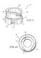
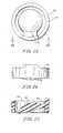
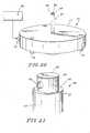
Figs. 9-19 , acartridge 50 mounting avalve flap 52 and avalve seat 54 is inserted from thetracheal end 24 intobarrel 22.Cartridge 50 is pushed intobarrel 22 past stops 46 and is captured betweenstops 46 and stop 44. The sloping sides ofstops 46 aid in the insertion ofcartridge 50 intobarrel 22.Cartridge 50 includes atracheal end 56 and anesophageal end 58.Esophageal end 58 is notched 60 along part of its perimeter to receive anelastomeric tab 62 by whichelastomeric valve flap 52 is molded to projected inwardly toward the center of anelastomeric ring 64.Ring 64,tab 62 andvalve flap 52 illustratively are molded as a single component from about 5 wt.% to about 11 wt.% silver oxide powder filled-NuSil Technology med-4960 silicone with a very small amount of an inhibitor, for example, .00043 wt.%, of 2-methy-3-butyn-2-ol.Ring 64 is received in a radially outwardly openinggroove 66 provided on the outer surface ofcartridge 50, withtab 62 oriented to extend throughnotch 60.Tab 62 andvalve flap 52 are molded at an angle of, for example, 15° from perpendicular to theaxis 48 ofdevice 20 to be biased againstseat 54 in the assembleddevice 20. A band orring 68 of, for example, titanium, is slipped aroundcartridge 50 overring 64 aftercartridge 50 is assembled, and beforecartridge 50 is inserted intobarrel 22. Cartridge 50 further includes twopassageways 72 which extend generally acrosscartridge 50 and are defined between chords of thecircular sidewall 74 which defines the outer dimension ofcartridge 50 when viewed from an end thereof. Oncecartridge 50 is assembled intobarrel 22, an amount of a material, such as, for example, a room temperature curing silicone adhesive, sufficient to fill eachpassageway 72 is introduced, for example, by using afixture 75 of the type illustrated inFigs. 20-21 . As best illustrated inFig. 14 , in the illustrated embodiment of thecartridge 50, thepassageways 72 intersect the inside diameter of thecartridge 50, and thus are accessible through it.Fixture 75 includes a base 77 havingadjustable legs 79 and aconnector 81 for connecting it to asource 83 of the material which is to be injected intopassageways 72. Aneedle 85 having acentral passageway 87 communicating withconnector 79 terminates adj acent atip 89 ofneedle 85 in twodiametrical openings 93 inneedle 85.Needle 85 also includes ashoulder 95 against which the tracheal end ofcartridge 50 rests, presentingopenings 93 at the inner ends of thepassageways 72.Passageways 72 are properly aligned in communication withopenings 93 by cooperatingfeatures needle 85 andcartridge 50, respectively. An amount of the material is then injected throughopenings 93 intopassageways 72 sufficient to fill them. The material may also be injected using (a) needle(s) throughsidewall 40 intopassageways 72. However the material is introduced, as the material cures in contact with theinner sidewall 40, it works to secure thecartridge 50, and thevalve barrel 22.Cartridge 50 illustratively is constructed from Kynar® 720 brand polyvinylidene fluoride (PVDF) or Estane® 58091 brand thermoplastic polyurethane (TPU). An illustrative room temperature curing silicone adhesive is NuSil Technology med-1511 room temperature vulcanizing (RTV) silicone adhesive.- Referring now to
Figs. 7-8 , in another embodiment, a barrel 122 includes a passageway 136 which in the illustrated embodiment is also generally right circular cylindrical. The inside diameter of sidewall 140 of the passageway 136 from the esophageal end 126 has as first dimension. From the tracheal end 124, the inside diameter tapers to a smaller diameter than the diameter of sidewall 140, providing a radially inwardly extending stop 144. Between stop 144 and the esophageal end 126 of barrel 122 the inside diameter of barrel 122 is constant. A number, again, illustratively five, of somewhat trapezoidal prism-shaped stops 146 project radially inwardly toward the axis 148 of device 120. Illustratively, stops 146 are perimetrally equally spaced at 72° intervals around sidewall 140. The region of barrel 122 between stop 144 and stops 146 is sized to accommodate thesame cartridge 50 as the embodiment ofFigs. 1-6 .
Claims (12)
- A method of making a voice prosthesis device (20) comprising providing a first passageway (36), inserting into the first passageway (36) a valve mechanism (50) for controlling flow through the first passageway (36), providing on the valve mechanism (50) at least one second passageway (72) that intersects a sidewall (40) of the first passageway (36) when the valve mechanism (50) is inserted into the first passageway (36), and filling the second passageway (72) with a material to fix the valve mechanism (50) in the first passageway (36).
- The method of claim 1 wherein providing on the valve mechanism (50) at least one second passageway (72) that intersects a sidewall (40) of the first passageway (36) when the valve mechanism (50) is inserted into the first passageway (36) comprises providing on the valve mechanism (50) at least one second passageway (72) that extends generally across the first passageway from a sidewall (40) of the first passageway (36) to a sidewall (40) of the first passageway (36) when the valve mechanism (50) is inserted into the first passageway (36).
- The method of claim 2 wherein providing on the valve mechanism (50) at least one second passageway (72) that extends generally across the first passageway (36) from a sidewall (40) of the first passageway (36) to a sidewall (40) of the first passageway (36) when the valve mechanism (50) is inserted into the first passageway (36) comprises providing on the valve mechanism (50) two second passageways (72) that extend generally across the first passageway (36) from a sidewall (40) of the first passageway to a sidewall (40) of the first passageway (36) when the valve mechanism (50) is inserted into the first passageway (36).
- The method of claim 3 wherein providing on the valve mechanism (50) two second passageways (72) that extend generally across the first passageway (36) from a sidewall (40) of the first passageway (36) to a sidewall (40) of the first passageway (36) when the valve mechanism (50) is inserted into the first passageway (36) comprises providing on the valve mechanism (50) two second passageways (72) that extend generally parallel to each other across the first passageway (36) from a sidewall (40) of the first passageway (36) to a sidewall (40) of the first passageway (36) when the valve mechanism (50) is inserted into the first passageway (36).
- The method of claim 1 further comprising forming adjacent a tracheal end of the first passageway (36) a tracheal flange (24) and forming adjacent an esophageal end of the first passageway (36) an esophageal flange (26).
- The method of claim 5 wherein inserting into the first passageway (36) a valve mechanism (50) comprises inserting into the first passageway (36) a valve mechanism (50) permitting flow through the first passageway (36) from the tracheal end (24) and impeding flow through the first passageway (36) from the esophageal end (26).
- A voice prosthesis device (20) for insertion into a tracheoesophageal opening of a wearer, the voice prosthesis device (20) comprising a first passageway (36), a valve mechanism (50) for inserting into the first passageway (36) for controlling flow through the first passageway (36), at least one second passageway (72) provided in the valve mechanism (50), the at least one second passageway (72) intersecting a sidewall (40) of the first passageway (36) when the valve mechanism (50) is inserted info the first passageway (36), the second passageway (72) containing a material to fix the valve mechanism (50) in the first passageway (36).
- The voice prosthesis device (20) of claim 7 wherein the at least one second passageway (72) that intersects a sidewall (40) of the first passageway (36) when the valve mechanism (50) is inserted into the first passageway (36) comprises at least one second passageway (72) that extends generally across the first passageway (36) from a sidewall (40) of the first passageway (36) to a sidewall (40) of the first passageway (36) when the valve mechanism (50) is inserted into the first passageway (36).
- The voice prosthesis device (20) of claim 8 wherein the at least one second passageway (72) that extends generally across the first passageway (36) from a sidewall (40) of the first passageway (36) to a sidewall (40) of the first passageway (36) when the valve mechanism (50) is inserted into the first passageway (36) comprises two second passageways (72) that extend generally across the first passageway (36) from a sidewall (40) of the first passageway (36) to a sidewall (40) of the first passageway (36) when the valve mechanism (50) is inserted into the first passageway (36).
- The voice prosthesis device (20) of claim 9 wherein the two second passageways (72) that extend generally across the first passageway (36) from a sidewall (40) of the first passageway (36) to a sidewall (40) of the first passageway (36) when the valve mechanism (50) is inserted into the first passageway (36) comprise two second passageways (72) that extend generally parallel to each other across the first passageway (36) from a sidewall (40) of the first passageway (36) to a sidewall (40) of the first passageway (36) when the valve mechanism (50) is inserted into the first passageway (36).
- The voice prosthesis device (20) of claim 7 further comprising a tracheal flange (24) adjacent a tracheal end of the first passageway (36) and an esophageal flange (26) adjacent an esophageal end of the first passageway (36).
- The voice prosthesis device (20) of claim 11 wherein the valve mechanism (50) for inserting into the first passageway (36) for controlling flow through the first passageway (36) comprises a valve mechanism (50) permitting flow through the first passageway (36) from the tracheal end (24) and impeding flow through the first passageway (36) from the esophageal end (26).
Priority Applications (1)
| Application Number | Priority Date | Filing Date | Title |
|---|---|---|---|
| PL09007165TPL2103283T3 (en) | 2005-06-06 | 2006-06-02 | Voice prosthesis device |
Applications Claiming Priority (2)
| Application Number | Priority Date | Filing Date | Title |
|---|---|---|---|
| US11/145,791US7998200B2 (en) | 2005-06-06 | 2005-06-06 | Voice prosthesis device |
| EP06011524AEP1736119B1 (en) | 2005-06-06 | 2006-06-02 | Voice prosthesis device |
Related Parent Applications (2)
| Application Number | Title | Priority Date | Filing Date |
|---|---|---|---|
| EP06011524.3Division | 2006-06-02 | ||
| EP06011524ADivisionEP1736119B1 (en) | 2005-06-06 | 2006-06-02 | Voice prosthesis device |
Publications (2)
| Publication Number | Publication Date |
|---|---|
| EP2103283A1true EP2103283A1 (en) | 2009-09-23 |
| EP2103283B1 EP2103283B1 (en) | 2010-09-22 |
Family
ID=37192675
Family Applications (2)
| Application Number | Title | Priority Date | Filing Date |
|---|---|---|---|
| EP09007165AActiveEP2103283B1 (en) | 2005-06-06 | 2006-06-02 | Voice prosthesis device |
| EP06011524AActiveEP1736119B1 (en) | 2005-06-06 | 2006-06-02 | Voice prosthesis device |
Family Applications After (1)
| Application Number | Title | Priority Date | Filing Date |
|---|---|---|---|
| EP06011524AActiveEP1736119B1 (en) | 2005-06-06 | 2006-06-02 | Voice prosthesis device |
Country Status (8)
| Country | Link |
|---|---|
| US (2) | US7998200B2 (en) |
| EP (2) | EP2103283B1 (en) |
| AU (2) | AU2006201493B9 (en) |
| CA (2) | CA2541887C (en) |
| DE (2) | DE602006007916D1 (en) |
| ES (2) | ES2328165T3 (en) |
| NZ (2) | NZ567068A (en) |
| PL (2) | PL2103283T3 (en) |
Families Citing this family (8)
| Publication number | Priority date | Publication date | Assignee | Title |
|---|---|---|---|---|
| GB0918995D0 (en)* | 2009-10-29 | 2009-12-16 | Univ Hull | A speech valve, a tool for facilitating insertion of a speech valve and a tool for holding a speech valve |
| FR2983060B1 (en) | 2011-11-30 | 2013-12-06 | Protip | MEDICAL SUPPORT DEVICE FOR IMPLANT OR PROSTHESIS |
| JP2015536219A (en)* | 2012-12-11 | 2015-12-21 | アトス メディカル アクティエボラーグ | Artificial larynx |
| FR3009951B1 (en) | 2013-09-05 | 2017-01-20 | Protip | INTRA-LARYNGEAL PROSTHESIS |
| WO2015123626A1 (en)* | 2014-02-17 | 2015-08-20 | The Johns Hopkins University | Tracheoesophageal prosthesis insufflator |
| WO2017068503A1 (en) | 2015-10-19 | 2017-04-27 | Rao Vishal Uchila Shishir | Tracheo esophageal voice prosthesis |
| US20190336276A1 (en)* | 2018-05-03 | 2019-11-07 | Brian Kamradt | Voice prosthesis with disposable inner cannual valve assembly |
| US11931250B2 (en) | 2018-05-03 | 2024-03-19 | Eon Meditech Pvt. Ltd. | Voice prosthesis with connecting feature |
Citations (32)
| Publication number | Priority date | Publication date | Assignee | Title |
|---|---|---|---|---|
| US3137299A (en) | 1961-07-28 | 1964-06-16 | Carl J Tabor | Tracheotomy tube |
| US4304228A (en) | 1980-07-14 | 1981-12-08 | Bivona Surgical Instruments, Inc. | Outside locking tracheal tube |
| US4325366A (en) | 1980-07-07 | 1982-04-20 | Tabor Carl J | Valve and method for use with a tracheotomy tube |
| US4435853A (en) | 1982-04-30 | 1984-03-13 | Hansa Medical Products, Inc. | Voice prosthesis device and placement tool therefor |
| US4582058A (en) | 1984-11-26 | 1986-04-15 | Bivona, Inc. | Tracheostoma valves |
| US4586931A (en) | 1981-12-11 | 1986-05-06 | Hansa Medical Products, Inc. | Auto actuatable switch, speech simulator and method for tracheotomized individuals |
| US4596248A (en)* | 1984-11-23 | 1986-06-24 | Lieberman Edgar M | Tracheostomy device |
| US4596579A (en)* | 1984-04-06 | 1986-06-24 | Pruitt Robert L | Voice prosthesis with tracheal guard |
| US4610691A (en) | 1983-06-30 | 1986-09-09 | Purdue Research Foundation | Voice prosthesis device |
| US4614516A (en) | 1982-04-30 | 1986-09-30 | Hansa Medical Products, Inc. | Voice prosthesis device |
| US4773412A (en) | 1986-08-25 | 1988-09-27 | Hansa Medical Products, Inc. | Speaking tracheostomy tube |
| US4808183A (en) | 1980-06-03 | 1989-02-28 | University Of Iowa Research Foundation | Voice button prosthesis and method for installing same |
| US4820304A (en) | 1987-07-13 | 1989-04-11 | Bivona, Inc. | Speech prosthesis device |
| US4911716A (en) | 1982-04-30 | 1990-03-27 | Hansa Medical Products, Inc. | Surgical implant for a voice prosthesis |
| US5027812A (en) | 1989-09-19 | 1991-07-02 | Bivona, Inc. | Tracheal tube for laser surgery |
| US5059208A (en) | 1991-02-04 | 1991-10-22 | Helix Medical, Inc. | Adjustable tracheostoma valve |
| US5064433A (en) | 1990-03-05 | 1991-11-12 | Helix Medical, Inc. | Voice prosthesis insertion assemblies |
| US5300119A (en) | 1992-01-10 | 1994-04-05 | Hansa Medical Products, Inc. | Delivery system |
| US5314470A (en) | 1989-12-27 | 1994-05-24 | Atos Medical Ab | Voice prosthesis |
| US5480432A (en) | 1994-07-27 | 1996-01-02 | Helix Medical Corporation | Extended dwell voice prosthesis |
| US5507809A (en) | 1993-11-05 | 1996-04-16 | Hansa Medical Products, Inc. | Multi-valved voice prosthesis |
| WO1996036386A1 (en)* | 1995-05-18 | 1996-11-21 | Ganz Franz Josef | Endotracheal cannula |
| US5578083A (en) | 1995-11-13 | 1996-11-26 | Helix Medical, Inc. | Voice prosthesis-cartridge assembly |
| US5738095A (en) | 1993-12-23 | 1998-04-14 | Atos Medical Ab | Tracheostoma device |
| US5919231A (en) | 1992-01-10 | 1999-07-06 | Hansa Medical Products, Inc. | Delivery system for voice prosthesis |
| US5957978A (en) | 1997-12-22 | 1999-09-28 | Hansa Medical Products, Inc. | Valved fenestrated tracheotomy tube |
| US5976151A (en) | 1995-12-22 | 1999-11-02 | Atos Medical Ab | Method and device for mounting a tubular element |
| US6422235B1 (en) | 1998-05-14 | 2002-07-23 | Atos Medical Ab | Vocal valve with filter |
| US6484345B2 (en) | 2001-02-13 | 2002-11-26 | Helix Medical, Inc. | Voice prosthesis brush |
| WO2003057082A1 (en) | 2001-12-28 | 2003-07-17 | Helix Medical, Inc. | Prosthesis with foldable flange |
| US6722367B1 (en) | 1997-12-22 | 2004-04-20 | Hansa Medical Products, Inc. | Valved fenestrated tracheotomy tube having outer and inner cannulae |
| US6772758B2 (en) | 1999-09-30 | 2004-08-10 | Atos Medical | Breathing protector |
Family Cites Families (6)
| Publication number | Priority date | Publication date | Assignee | Title |
|---|---|---|---|---|
| FR2494581A1 (en) | 1980-11-25 | 1982-05-28 | Delacroix Chevalier | Phonetic tube for insertion following laryngectomy - pref. has a moulded plastic body fitted with a silver flap valve |
| US4538607A (en)* | 1984-02-06 | 1985-09-03 | Ab Fixfabriken | Tracheostomy valve |
| US20020193879A1 (en) | 2001-04-11 | 2002-12-19 | Seder Edmund V. | Medical devices having antimicrobial properties |
| US6948526B2 (en)* | 2001-12-28 | 2005-09-27 | Helix Medical, Inc. | Valve mounting assembly for voice prosthesis-cartridge and ring |
| US8317861B2 (en)* | 2001-04-11 | 2012-11-27 | Helix Medical, Llc | Antimicrobial indwelling voice prosthesis |
| US7021314B1 (en)* | 2004-07-19 | 2006-04-04 | Lane Charles J | Stoma stent with integrated speech flap valve |
- 2005
- 2005-06-06USUS11/145,791patent/US7998200B2/enactiveActive
- 2006
- 2006-04-03CACA2541887Apatent/CA2541887C/enactiveActive
- 2006-04-03CACA2735835Apatent/CA2735835C/enactiveActive
- 2006-04-10AUAU2006201493Apatent/AU2006201493B9/enactiveActive
- 2006-04-11NZNZ567068Apatent/NZ567068A/enunknown
- 2006-04-11NZNZ546524Apatent/NZ546524A/ennot_activeIP Right Cessation
- 2006-06-02ESES06011524Tpatent/ES2328165T3/enactiveActive
- 2006-06-02PLPL09007165Tpatent/PL2103283T3/enunknown
- 2006-06-02EPEP09007165Apatent/EP2103283B1/enactiveActive
- 2006-06-02DEDE602006007916Tpatent/DE602006007916D1/enactiveActive
- 2006-06-02PLPL06011524Tpatent/PL1736119T3/enunknown
- 2006-06-02ESES09007165Tpatent/ES2352169T3/enactiveActive
- 2006-06-02DEDE602006017125Tpatent/DE602006017125D1/enactiveActive
- 2006-06-02EPEP06011524Apatent/EP1736119B1/enactiveActive
- 2009
- 2009-10-12AUAU2009225313Apatent/AU2009225313B2/enactiveActive
- 2011
- 2011-07-01USUS13/174,945patent/US20110264214A1/ennot_activeAbandoned
Patent Citations (36)
| Publication number | Priority date | Publication date | Assignee | Title |
|---|---|---|---|---|
| US3137299A (en) | 1961-07-28 | 1964-06-16 | Carl J Tabor | Tracheotomy tube |
| US4808183A (en) | 1980-06-03 | 1989-02-28 | University Of Iowa Research Foundation | Voice button prosthesis and method for installing same |
| US4325366A (en) | 1980-07-07 | 1982-04-20 | Tabor Carl J | Valve and method for use with a tracheotomy tube |
| US4304228A (en) | 1980-07-14 | 1981-12-08 | Bivona Surgical Instruments, Inc. | Outside locking tracheal tube |
| US4586931A (en) | 1981-12-11 | 1986-05-06 | Hansa Medical Products, Inc. | Auto actuatable switch, speech simulator and method for tracheotomized individuals |
| US4614516A (en) | 1982-04-30 | 1986-09-30 | Hansa Medical Products, Inc. | Voice prosthesis device |
| US4435853A (en) | 1982-04-30 | 1984-03-13 | Hansa Medical Products, Inc. | Voice prosthesis device and placement tool therefor |
| US4911716A (en) | 1982-04-30 | 1990-03-27 | Hansa Medical Products, Inc. | Surgical implant for a voice prosthesis |
| US4610691A (en) | 1983-06-30 | 1986-09-09 | Purdue Research Foundation | Voice prosthesis device |
| US4596579A (en)* | 1984-04-06 | 1986-06-24 | Pruitt Robert L | Voice prosthesis with tracheal guard |
| US4596248A (en)* | 1984-11-23 | 1986-06-24 | Lieberman Edgar M | Tracheostomy device |
| US4582058A (en) | 1984-11-26 | 1986-04-15 | Bivona, Inc. | Tracheostoma valves |
| US4773412A (en) | 1986-08-25 | 1988-09-27 | Hansa Medical Products, Inc. | Speaking tracheostomy tube |
| US4820304A (en) | 1987-07-13 | 1989-04-11 | Bivona, Inc. | Speech prosthesis device |
| US5027812A (en) | 1989-09-19 | 1991-07-02 | Bivona, Inc. | Tracheal tube for laser surgery |
| US5314470A (en) | 1989-12-27 | 1994-05-24 | Atos Medical Ab | Voice prosthesis |
| US5064433A (en) | 1990-03-05 | 1991-11-12 | Helix Medical, Inc. | Voice prosthesis insertion assemblies |
| US5059208A (en) | 1991-02-04 | 1991-10-22 | Helix Medical, Inc. | Adjustable tracheostoma valve |
| US5300119A (en) | 1992-01-10 | 1994-04-05 | Hansa Medical Products, Inc. | Delivery system |
| US6776797B1 (en) | 1992-01-10 | 2004-08-17 | Hansa Medical Products, Inc. | Method of inserting a flanged device into a human body |
| US5571180A (en) | 1992-01-10 | 1996-11-05 | Hansa Medical Products, Inc. | Tool for loading flexible flange into retainer |
| US5919231A (en) | 1992-01-10 | 1999-07-06 | Hansa Medical Products, Inc. | Delivery system for voice prosthesis |
| US5507809A (en) | 1993-11-05 | 1996-04-16 | Hansa Medical Products, Inc. | Multi-valved voice prosthesis |
| US5738095A (en) | 1993-12-23 | 1998-04-14 | Atos Medical Ab | Tracheostoma device |
| US5632775A (en) | 1994-07-27 | 1997-05-27 | Helix Medical, Inc. | Extended dwell voice prosthesis |
| US5480432A (en) | 1994-07-27 | 1996-01-02 | Helix Medical Corporation | Extended dwell voice prosthesis |
| WO1996036386A1 (en)* | 1995-05-18 | 1996-11-21 | Ganz Franz Josef | Endotracheal cannula |
| US5693097A (en) | 1995-11-13 | 1997-12-02 | Helix Medical, Inc. | Voice prosthesis-cartridge assembly |
| US5578083A (en) | 1995-11-13 | 1996-11-26 | Helix Medical, Inc. | Voice prosthesis-cartridge assembly |
| US5976151A (en) | 1995-12-22 | 1999-11-02 | Atos Medical Ab | Method and device for mounting a tubular element |
| US5957978A (en) | 1997-12-22 | 1999-09-28 | Hansa Medical Products, Inc. | Valved fenestrated tracheotomy tube |
| US6722367B1 (en) | 1997-12-22 | 2004-04-20 | Hansa Medical Products, Inc. | Valved fenestrated tracheotomy tube having outer and inner cannulae |
| US6422235B1 (en) | 1998-05-14 | 2002-07-23 | Atos Medical Ab | Vocal valve with filter |
| US6772758B2 (en) | 1999-09-30 | 2004-08-10 | Atos Medical | Breathing protector |
| US6484345B2 (en) | 2001-02-13 | 2002-11-26 | Helix Medical, Inc. | Voice prosthesis brush |
| WO2003057082A1 (en) | 2001-12-28 | 2003-07-17 | Helix Medical, Inc. | Prosthesis with foldable flange |
Also Published As
| Publication number | Publication date |
|---|---|
| CA2541887A1 (en) | 2006-12-06 |
| NZ546524A (en) | 2008-04-30 |
| AU2006201493B9 (en) | 2009-08-13 |
| AU2009225313B2 (en) | 2011-12-08 |
| US20110264214A1 (en) | 2011-10-27 |
| AU2009225313A1 (en) | 2009-11-05 |
| ES2352169T3 (en) | 2011-02-16 |
| AU2006201493A2 (en) | 2008-06-19 |
| AU2006201493B2 (en) | 2009-07-16 |
| US7998200B2 (en) | 2011-08-16 |
| EP1736119A2 (en) | 2006-12-27 |
| AU2006201493A1 (en) | 2006-12-21 |
| EP1736119B1 (en) | 2009-07-22 |
| CA2735835C (en) | 2013-04-02 |
| EP2103283B1 (en) | 2010-09-22 |
| ES2328165T3 (en) | 2009-11-10 |
| DE602006017125D1 (en) | 2010-11-04 |
| CA2735835A1 (en) | 2006-12-06 |
| PL1736119T3 (en) | 2009-12-31 |
| NZ567068A (en) | 2009-07-31 |
| EP1736119A3 (en) | 2007-09-12 |
| US20060276893A1 (en) | 2006-12-07 |
| PL2103283T3 (en) | 2011-03-31 |
| CA2541887C (en) | 2011-05-31 |
| DE602006007916D1 (en) | 2009-09-03 |
Similar Documents
| Publication | Publication Date | Title |
|---|---|---|
| US20110264214A1 (en) | Voice Prosthesis Device | |
| US10300275B2 (en) | Magnet installation systems and methods for use with cochlear implants | |
| US6860463B2 (en) | Access valve | |
| AU2015217443B2 (en) | Rigid needle shield gripping cap assembly | |
| US5312362A (en) | Seal for a cannula assembly | |
| AU2007215555B2 (en) | Needleless access port valves | |
| AU2008202240B2 (en) | Access assembly with ribbed seal | |
| CA2215182A1 (en) | Deformable intraocular lens injecting device | |
| US20040199173A1 (en) | Cartridge for an intraocular lens | |
| EP1733703B1 (en) | Voice prosthesis device | |
| US20070093851A1 (en) | Surgical seal | |
| KR20190037235A (en) | Damage prevention connector for long feeding device | |
| EP3381420B1 (en) | Piercing needle-equipped cannula | |
| US20210152960A1 (en) | Apparatuses for coupling to hearing aids | |
| JP2023520239A (en) | Subcutaneous port with locking member | |
| AU2002346618A1 (en) | Access valve | |
| JP2005027956A (en) | Medical tools | |
| EP2139552A1 (en) | A suture sleeve and a method for implanting one or more electrical leads into a vein |
Legal Events
| Date | Code | Title | Description |
|---|---|---|---|
| PUAI | Public reference made under article 153(3) epc to a published international application that has entered the european phase | Free format text:ORIGINAL CODE: 0009012 | |
| AC | Divisional application: reference to earlier application | Ref document number:1736119 Country of ref document:EP Kind code of ref document:P | |
| AK | Designated contracting states | Kind code of ref document:A1 Designated state(s):DE ES GB IT PL SE | |
| 17P | Request for examination filed | Effective date:20100308 | |
| GRAP | Despatch of communication of intention to grant a patent | Free format text:ORIGINAL CODE: EPIDOSNIGR1 | |
| GRAS | Grant fee paid | Free format text:ORIGINAL CODE: EPIDOSNIGR3 | |
| GRAA | (expected) grant | Free format text:ORIGINAL CODE: 0009210 | |
| AC | Divisional application: reference to earlier application | Ref document number:1736119 Country of ref document:EP Kind code of ref document:P | |
| AK | Designated contracting states | Kind code of ref document:B1 Designated state(s):DE ES GB IT PL SE | |
| REG | Reference to a national code | Ref country code:GB Ref legal event code:FG4D | |
| REF | Corresponds to: | Ref document number:602006017125 Country of ref document:DE Date of ref document:20101104 Kind code of ref document:P | |
| REG | Reference to a national code | Ref country code:SE Ref legal event code:TRGR | |
| REG | Reference to a national code | Ref country code:ES Ref legal event code:FG2A Effective date:20110204 | |
| REG | Reference to a national code | Ref country code:PL Ref legal event code:T3 | |
| PLBE | No opposition filed within time limit | Free format text:ORIGINAL CODE: 0009261 | |
| STAA | Information on the status of an ep patent application or granted ep patent | Free format text:STATUS: NO OPPOSITION FILED WITHIN TIME LIMIT | |
| 26N | No opposition filed | Effective date:20110623 | |
| REG | Reference to a national code | Ref country code:DE Ref legal event code:R097 Ref document number:602006017125 Country of ref document:DE Effective date:20110623 | |
| REG | Reference to a national code | Ref country code:DE Ref legal event code:R082 Ref document number:602006017125 Country of ref document:DE Representative=s name:PFENNING, MEINIG & PARTNER MBB PATENTANWAELTE, DE Ref country code:DE Ref legal event code:R081 Ref document number:602006017125 Country of ref document:DE Owner name:FREUDENBERG MEDICAL, LLC (N.D.GES.D.STAATES DE, US Free format text:FORMER OWNER: HELIX MEDICAL, LLC, PLYMOUTH, MICH., US | |
| PGFP | Annual fee paid to national office [announced via postgrant information from national office to epo] | Ref country code:GB Payment date:20240625 Year of fee payment:19 | |
| PGFP | Annual fee paid to national office [announced via postgrant information from national office to epo] | Ref country code:DE Payment date:20240627 Year of fee payment:19 | |
| PGFP | Annual fee paid to national office [announced via postgrant information from national office to epo] | Ref country code:PL Payment date:20240529 Year of fee payment:19 | |
| PGFP | Annual fee paid to national office [announced via postgrant information from national office to epo] | Ref country code:SE Payment date:20240626 Year of fee payment:19 | |
| PGFP | Annual fee paid to national office [announced via postgrant information from national office to epo] | Ref country code:IT Payment date:20240627 Year of fee payment:19 | |
| PGFP | Annual fee paid to national office [announced via postgrant information from national office to epo] | Ref country code:ES Payment date:20240701 Year of fee payment:19 |