EP2103191B1 - Systems and methods for thermal management of lamps and luminaires using led sources - Google Patents
Systems and methods for thermal management of lamps and luminaires using led sourcesDownload PDFInfo
- Publication number
- EP2103191B1 EP2103191B1EP07864872.2AEP07864872AEP2103191B1EP 2103191 B1EP2103191 B1EP 2103191B1EP 07864872 AEP07864872 AEP 07864872AEP 2103191 B1EP2103191 B1EP 2103191B1
- Authority
- EP
- European Patent Office
- Prior art keywords
- led
- heat pipe
- luminaire
- lighting apparatus
- contact pad
- Prior art date
- Legal status (The legal status is an assumption and is not a legal conclusion. Google has not performed a legal analysis and makes no representation as to the accuracy of the status listed.)
- Not-in-force
Links
- 238000000034methodMethods0.000titledescription3
- 230000013011matingEffects0.000claimsdescription20
- 238000012546transferMethods0.000description12
- 239000012530fluidSubstances0.000description9
- 239000000758substrateSubstances0.000description9
- 230000003287optical effectEffects0.000description8
- QHZSDTDMQZPUKC-UHFFFAOYSA-N3,5-dichlorobiphenylChemical compoundClC1=CC(Cl)=CC(C=2C=CC=CC=2)=C1QHZSDTDMQZPUKC-UHFFFAOYSA-N0.000description7
- 230000008901benefitEffects0.000description4
- 239000007788liquidSubstances0.000description4
- 238000013459approachMethods0.000description3
- 230000008859changeEffects0.000description3
- 238000006243chemical reactionMethods0.000description3
- 238000001816coolingMethods0.000description3
- 238000005516engineering processMethods0.000description3
- 238000001704evaporationMethods0.000description3
- 230000008020evaporationEffects0.000description3
- 230000006872improvementEffects0.000description3
- 239000000463materialSubstances0.000description3
- 230000007246mechanismEffects0.000description3
- 230000000295complement effectEffects0.000description2
- 238000013329compoundingMethods0.000description2
- 238000005286illuminationMethods0.000description2
- 238000012986modificationMethods0.000description2
- 230000004048modificationEffects0.000description2
- 150000003071polychlorinated biphenylsChemical class0.000description2
- 230000005855radiationEffects0.000description2
- 229910000679solderInorganic materials0.000description2
- 230000009471actionEffects0.000description1
- 230000000712assemblyEffects0.000description1
- 238000000429assemblyMethods0.000description1
- 238000009835boilingMethods0.000description1
- 238000010276constructionMethods0.000description1
- 230000008878couplingEffects0.000description1
- 238000010168coupling processMethods0.000description1
- 238000005859coupling reactionMethods0.000description1
- 238000013461designMethods0.000description1
- 230000000694effectsEffects0.000description1
- 239000008393encapsulating agentSubstances0.000description1
- 239000011521glassSubstances0.000description1
- 238000009434installationMethods0.000description1
- 239000011810insulating materialSubstances0.000description1
- 238000002955isolationMethods0.000description1
- 239000002184metalSubstances0.000description1
- 229910001507metal halideInorganic materials0.000description1
- 150000005309metal halidesChemical class0.000description1
- 230000000116mitigating effectEffects0.000description1
- 230000007935neutral effectEffects0.000description1
- 230000021715photosynthesis, light harvestingEffects0.000description1
- 230000002028prematureEffects0.000description1
- 230000008569processEffects0.000description1
- 230000000135prohibitive effectEffects0.000description1
- 238000011867re-evaluationMethods0.000description1
- 230000009467reductionEffects0.000description1
- 238000010572single replacement reactionMethods0.000description1
- 238000009834vaporizationMethods0.000description1
- 230000008016vaporizationEffects0.000description1
- 238000001429visible spectrumMethods0.000description1
Images


Classifications
- F—MECHANICAL ENGINEERING; LIGHTING; HEATING; WEAPONS; BLASTING
- F21—LIGHTING
- F21V—FUNCTIONAL FEATURES OR DETAILS OF LIGHTING DEVICES OR SYSTEMS THEREOF; STRUCTURAL COMBINATIONS OF LIGHTING DEVICES WITH OTHER ARTICLES, NOT OTHERWISE PROVIDED FOR
- F21V29/00—Protecting lighting devices from thermal damage; Cooling or heating arrangements specially adapted for lighting devices or systems
- F21V29/50—Cooling arrangements
- F21V29/51—Cooling arrangements using condensation or evaporation of a fluid, e.g. heat pipes
- F—MECHANICAL ENGINEERING; LIGHTING; HEATING; WEAPONS; BLASTING
- F21—LIGHTING
- F21V—FUNCTIONAL FEATURES OR DETAILS OF LIGHTING DEVICES OR SYSTEMS THEREOF; STRUCTURAL COMBINATIONS OF LIGHTING DEVICES WITH OTHER ARTICLES, NOT OTHERWISE PROVIDED FOR
- F21V29/00—Protecting lighting devices from thermal damage; Cooling or heating arrangements specially adapted for lighting devices or systems
- F21V29/50—Cooling arrangements
- F21V29/70—Cooling arrangements characterised by passive heat-dissipating elements, e.g. heat-sinks
- F21V29/74—Cooling arrangements characterised by passive heat-dissipating elements, e.g. heat-sinks with fins or blades
- F21V29/75—Cooling arrangements characterised by passive heat-dissipating elements, e.g. heat-sinks with fins or blades with fins or blades having different shapes, thicknesses or spacing
- F—MECHANICAL ENGINEERING; LIGHTING; HEATING; WEAPONS; BLASTING
- F21—LIGHTING
- F21V—FUNCTIONAL FEATURES OR DETAILS OF LIGHTING DEVICES OR SYSTEMS THEREOF; STRUCTURAL COMBINATIONS OF LIGHTING DEVICES WITH OTHER ARTICLES, NOT OTHERWISE PROVIDED FOR
- F21V29/00—Protecting lighting devices from thermal damage; Cooling or heating arrangements specially adapted for lighting devices or systems
- F21V29/50—Cooling arrangements
- F21V29/70—Cooling arrangements characterised by passive heat-dissipating elements, e.g. heat-sinks
- F21V29/74—Cooling arrangements characterised by passive heat-dissipating elements, e.g. heat-sinks with fins or blades
- F21V29/76—Cooling arrangements characterised by passive heat-dissipating elements, e.g. heat-sinks with fins or blades with essentially identical parallel planar fins or blades, e.g. with comb-like cross-section
- F21V29/767—Cooling arrangements characterised by passive heat-dissipating elements, e.g. heat-sinks with fins or blades with essentially identical parallel planar fins or blades, e.g. with comb-like cross-section the planes containing the fins or blades having directions perpendicular to the light emitting axis
- F—MECHANICAL ENGINEERING; LIGHTING; HEATING; WEAPONS; BLASTING
- F21—LIGHTING
- F21K—NON-ELECTRIC LIGHT SOURCES USING LUMINESCENCE; LIGHT SOURCES USING ELECTROCHEMILUMINESCENCE; LIGHT SOURCES USING CHARGES OF COMBUSTIBLE MATERIAL; LIGHT SOURCES USING SEMICONDUCTOR DEVICES AS LIGHT-GENERATING ELEMENTS; LIGHT SOURCES NOT OTHERWISE PROVIDED FOR
- F21K9/00—Light sources using semiconductor devices as light-generating elements, e.g. using light-emitting diodes [LED] or lasers
- F—MECHANICAL ENGINEERING; LIGHTING; HEATING; WEAPONS; BLASTING
- F21—LIGHTING
- F21V—FUNCTIONAL FEATURES OR DETAILS OF LIGHTING DEVICES OR SYSTEMS THEREOF; STRUCTURAL COMBINATIONS OF LIGHTING DEVICES WITH OTHER ARTICLES, NOT OTHERWISE PROVIDED FOR
- F21V23/00—Arrangement of electric circuit elements in or on lighting devices
- F21V23/04—Arrangement of electric circuit elements in or on lighting devices the elements being switches
- F—MECHANICAL ENGINEERING; LIGHTING; HEATING; WEAPONS; BLASTING
- F21—LIGHTING
- F21Y—INDEXING SCHEME ASSOCIATED WITH SUBCLASSES F21K, F21L, F21S and F21V, RELATING TO THE FORM OR THE KIND OF THE LIGHT SOURCES OR OF THE COLOUR OF THE LIGHT EMITTED
- F21Y2107/00—Light sources with three-dimensionally disposed light-generating elements
- F—MECHANICAL ENGINEERING; LIGHTING; HEATING; WEAPONS; BLASTING
- F21—LIGHTING
- F21Y—INDEXING SCHEME ASSOCIATED WITH SUBCLASSES F21K, F21L, F21S and F21V, RELATING TO THE FORM OR THE KIND OF THE LIGHT SOURCES OR OF THE COLOUR OF THE LIGHT EMITTED
- F21Y2115/00—Light-generating elements of semiconductor light sources
- F21Y2115/10—Light-emitting diodes [LED]
- Y—GENERAL TAGGING OF NEW TECHNOLOGICAL DEVELOPMENTS; GENERAL TAGGING OF CROSS-SECTIONAL TECHNOLOGIES SPANNING OVER SEVERAL SECTIONS OF THE IPC; TECHNICAL SUBJECTS COVERED BY FORMER USPC CROSS-REFERENCE ART COLLECTIONS [XRACs] AND DIGESTS
- Y10—TECHNICAL SUBJECTS COVERED BY FORMER USPC
- Y10S—TECHNICAL SUBJECTS COVERED BY FORMER USPC CROSS-REFERENCE ART COLLECTIONS [XRACs] AND DIGESTS
- Y10S362/00—Illumination
- Y10S362/80—Light emitting diode
Definitions
- This inventionrelates to thermal management for light emitting diode based lighting systems.
- a lampThe purpose of a lamp is to convert electrical energy to visible light.
- lampsused in the lighting industry. Some examples are high intensity discharge (“HID”), fluorescent, incandescent, and light emitting diode (“LED”).
- HIDhigh intensity discharge
- LEDlight emitting diode
- Each of these lampsemits and dissipates energy in the form of radiant energy and heat in various amounts.
- a 400 watt metal halide lampconverts approximately 112 watts to visible energy, 20 watts to UV energy, 72 watts to IR energy, while the remaining 200 watts of energy is converted to heat and dissipated to the surrounding environment via conduction through the lamp base and convection off the glass envelope.
- An LED used for lighting or illuminationconverts electrical energy to light in a fundamentally different way than HID, fluorescent, and incandescent lamps, resulting in very little radiant energy outside the visible spectrum.
- the bulk of the energy lost in the conversion processis dissipated as thermal energy through the LED chip and the mechanical structure that surrounds it.
- the energy conversions (percent of electrical energy input) for the aforementioned light sourcesare shown in the Table 1.
- US 2004/0213016An example of an automotive lighting assembly cooling system is shown in US 2004/0213016 .
- a lighting assemblyincludes a heat pipe with an evaporation area proximate to a heat generating component, such as an LED, and a condensing area located remote from the evaporation area. Evaporation of fluid within the heat pipe transfers heat away from the heat generating component.
- the efficiency of the cooling system in one embodiment shown in US 2004/0213016is increased by including fins associated with the condensing area and placing the fins in an area where air flow external to a moving vehicle assists in cooling the fins.
- a significant amount of energyis converted to heat by the lamp.
- the heat generated by the lampmay cause problems related to the basic function of the lamp and luminaire.
- Benefits associated with effective removal of thermal energy from within the luminaireinclude improved luminaire life, smaller (lower cost) package sizes, and improved lumen output in some lamp types, such as fluorescent and LED.
- An additional benefit of removing heat from the luminaireis that the luminaire may then be operated in a higher ambient temperature environment without compromising luminaire life or performance. In the case of an LED, better thermal management allows the LED to be driven at higher power levels while mitigating the negative effects on life and light output normally associated with higher power input levels.
- Conductionoccurs when LED chips, the mechanical structure of the LEDs, the LED mounting structure (such as printed circuit boards), and the luminaire housing are placed in physical contact with one another. Physical contact with the LEDs is generally optimized to provide electrical power and mechanical support Traditional means of providing electrical and mechanical contact between LEDs and the luminaire provide poor means of conduction between the LEDs and external luminaire surfaces (such as die cast housing). In addition, the location of LEDs is often determined by the desired optical performance of the luminaire.
- a further disadvantage of using a thermally conductive structure within the luminaire envelopeis that it allows dissipation of heat into the enclosure, which is generally sealed. This effectively raises the ambient temperature of the air surrounding the LEDs, thus compounding thermal related failures.
- Convectionoccurs at any surface exposed to air, but may be limited by the amount of air movement near the emitting surface, the surface area available for dissipation, and the difference between the temperature of the emitting surface and the surrounding air.
- the luminaireis enclosed further restricting airflow around the LEDs.
- heat generated by the LEDsis transferred by convection to the air within the enclosure, but cannot escape the boundaries of the enclosure.
- the LEDitself does not contribute significant amounts of heat due to its small size, the components that are used to mount the LEDs are often large, thus allowing greater dissipation to the air within the enclosure by convection.
- the air within the enclosureexperiences a build up of heat, which elevates lamp and luminaire temperatures and may lead to heat related failures. For example, in luminaires with electronic ballasts and components, excessive heat can shorten the life of the electronic components, resulting in premature failure of the lighting system.
- Radiationis the movement of energy from one point to another via electromagnetic propagation. Much of the radiant energy escapes the luminaire through the clear optical elements (light emitting zones, lenses, etc) and reflectors, which are designed to redirect the radiant energy (visible light in particular) out of the luminaire according to the needs of the application.
- the radiant energy that does not escape through the lensesis absorbed by the various materials within the luminaire and converted into heat.
- a heat pipeis a tube, usually comprised of metal, that is evacuated and sealed with a small amount of fluid inside. Because the tube is sealed and evacuated, the working fluid changes from liquid to vapor at a relatively low temperature compared to the boiling point of that fluid at normal atmospheric pressure. The choice of fluid and internal pressure determine the temperature at which vaporization occurs. When a heat source is applied, the fluid will vaporize and uniformly fill the tube, resulting in a state of equilibrium where the fluid exists in both liquid and vapor form based on the amount of heat applied. If there is a location on the tube wall that is cooler than the area where the heat source is applied, the vapor will condense at that location. When fluid changes state from vapor to liquid, large amounts of energy are released.
- a capillary structureWith the addition of a special structure inside the tube, called a capillary structure, the fluid in liquid form will readily return to the spot where the heat source is applied via capillary action.
- the addition of the capillary structure within the tubecreates a double-phase change convective thermal transfer loop that achieves a high thermal transfer coefficient over relatively large distances and small cross-sectional areas compared to what can be achieved with other thermal transfer structures.
- a heat pipethus allows a relatively small heat producing area to be coupled to a large heat-dissipating surface that is far away from the heat source using a relatively small cross-sectional area structure to couple to the heat source and transfer the heat to the larger dissipating region.
- Such an arrangementis advantageous when the heat source is located inside an enclosed cavity with limited surface area or complex geometry for coupling to and dissipating heat.
- LEDsare very new to the market within the historical perspective of HID and fluorescent light source availability. Because LED technology is new and rapidly developing, the form factor of individual LEDs and the efficacy of LEDs change on a yearly basis. LEDs that were introduced as little as five years ago are no longer available today. LEDs that were introduced a year ago have efficacy improvement of 20 to 50%. This means that an owner, performing the simple act of purchasing replacement LEDs, will have to reconsider the impact on light levels, type of optics used, LED drivers, and thermal performance of the system.
- LED light sources within luminaireswill have a lifetime of 50,000 hours. This may seem like a long time to people unfamiliar with luminaire construction, or those accustomed to residential lighting systems. A lifetime of 50,000 hours, however, is not exceptional within the general lighting industry as HID and fluorescent light sources with typical lifetimes of 20,000 to 100,000 hours have been used for decades. Furthermore, while these light sources generally provide longer life, it is desirable that they are serviceable in the event of a failure because the installed lifetime of luminaires greatly exceed the lifetime of even a 100,000 hour light source, and thus the thermal path should be able to be engaged and disengaged in a highly repeatable method with minimal introduction of thermal resistances.
- an LED based lighting systemthat includes an optimized conduction path and dissipation area to significantly reduce the amount of heat transferred from the LEDs to the interior of the enclosure, thereby allowing LED luminaires to operate in a higher ambient temperature environment without compromising luminaire life or performance. Additionally, there is a need for LED based lighting systems that allow for forward compatibility of LED changes without impact to the form factor, thermal, or optical performance of the luminaire. Finally, there is a need for LED based lighting systems that provide for LED replacement with minimal introduction of thermal resistances into the thermal path by ensuring that the thermal path engages and disengages in a highly repeatable manner.
- a lighting apparatuscomprises an LED module assembly which in turn comprises a heat pipe with an exterior surface which is connected to at least one contact pad, where this combination forms a thermal assembly.
- the LED module assemblyfurther comprises at least one light emitting diode coupled to the contact pad.
- the heat pipecomprises a first end and a second end, wherein the first end of the heat pipe is coupled to a heat pipe mating surface.
- the lighting apparatusis characterised in that it comprises a luminaire housing.
- An inner surface of the luminaire housingcomprises a housing mating surface, and the heat pipe mating surface is configured to contact and releasably mate with the housing mating surface to define a thermal junction.
- the lighting apparatusis further characterised in that it comprises a luminaire base, wherein the luminaire base is coupled to the second end of the heat pipe and coupled to the luminaire housing wherein the first end and the second end of the heat pipe are enclosed by the coupled luminaire housing and the luminaire base.
- an LED drivermay be connected in close proximity to the thermal assembly and may be a PWM dimming driver.
- the light emitting diodecomprises an individual LED, an LED chip, or an LED die mounted to a printed circuit board coupled to the contact pad. In other embodiments, the light emitting diode comprises a printed circuit board coupled to an individual LED, an LED chip, or an LED die mounted directly to the surface of the contact pad. In some embodiments where the light emitting diode is mounted directly to the contact pad, the surface of the contact pad has at least one groove substantially parallel and opposite at least one electrical contact area on the surface of the light emitting diode to prevent contact between the electrical contact area and the contact pad.
- the contact pad and the light emitting diodeare dimensioned to have substantially similar surface areas. In other embodiments, the contact pad is dimensioned to accommodate a plurality of light emitting diodes.
- a thermal junctionis located between the heat pipe mating surface and an interior surface of a luminaire housing adjacent to an external heat sink.
- Some embodimentsinclude a member attached to the luminaire housing that adjusts the position of the LED module assembly with respect to the housing and configured to apply mechanical force to the thermal junction when the heat pipe surface contacts the interior surface of the housing.
- the membermay be a spring loaded latch engaging and disengaging the LED module assembly at the thermal junction.
- An embodiment of the present inventionproposes to reduce the thermal issues associated with lamp energy dissipation by implementing an optimized conduction path from the lamp to the exterior of the luminaire, away from thermally sensitive components, through the use of heat pipes integrated into an LED module assembly and luminaire.
- One advantage of using a heat pipe for thermal managementis that it is a passive device, requiring no electrical energy or temperature sensing circuitry to operate. In such an embodiment, a significant reduction in thermal transfer to the interior of the enclosure may be implemented, while allowing maximum dissipation of energy from the LEDs.
- an LED module assembly 8includes a plurality of LEDs 10 surrounded by a structure 12.
- Each LED 10is mounted to a surface of a printed circuit board ("PCB") 14.
- the surfaces of PCB 14 opposite the surfaces coupled to LEDs 10are coupled to a plurality of thermal transfer interfaces ("contact pads") 16 that are in turn coupled to internal heat pipe 18.
- the structure including the connection of contact pads 16 to internal heat pipe 18is referred to as thermal assembly 19.
- One end of thermal assembly 19is connected to a heat pipe mating surface 20.
- the opposing end of thermal assembly 19contains an aperture 22 designed to receive protuberance 24 located on base 26, as shown in Fig. 3 .
- LEDs 10, PCB 14, and structure 12are collectively referred to as LED mounting structure 28.
- structure 12substantially covers LEDs 10, PCBs 14, and thermal assembly 19 to ensure that the heat pipe is the main conduit for flow of thermal energy.
- structure 12is a material with a low thermal conductivity. In another embodiment, structure 12 is a thermally insulating material.
- contact pad 16 and LED 10are dimensioned to have substantially similar surface areas. In other embodiments, contact pad 16 is dimensioned to accommodate a plurality of LEDs 10, thus allowing greater flexibility in positioning LEDs 10 as needed to meet optical performance requirements.
- LED replacementis incorporated into the present invention to allow for forward compatibility of the LED lamp and to allow replacement LED module assemblies 8 to be manufactured in a manner that does not affect the optical or thermal performance of the original luminaire 32 (shown in Figs. 4-6 ) and its LED module assembly 8 as the replacement unit will have LEDs 10 in the same physical location relative to the optics, and also incorporate the same thermal mechanism (internal heat pipe 18). With higher efficacy LEDs 10 driven in a dimmed state in the same physical location, optical performance equivalent to the original luminaire 32 and LED module assembly 8 is achieved.
- Fig. 2is a rotated and partially exploded view of LED module assembly 8 and including LED driver 30 that is connected to a contact pad 16 adjacent to two LED mounting structures 28.
- LEDs 10 and LED driver 30are serviceable as a single LED module assembly 8.
- An exemplary LED driver 30has a lifetime of 50,000 hours, which is complementary to the lifetime of LEDs 10, and thus replacement of a single LED module assembly 8 containing both LEDs 10 and LED driver 30 will minimize service costs.
- an LED module assembly 8 containing both LEDs 10 and LED driver 30provides for forward compatibility of the LED lamp. By integrating LED driver 30 with LEDs 10 in a single replacement LED module assembly 8, LED driver 30 may be appropriately designed for future LEDs 10 with improved efficacy. Several approaches are available to enable this forward compatibility of driver and LEDs.
- LED driver 30may be designed as a PWM dimming driver, thus allowing LEDs 10 to be dimmed to factory specified levels that match the original LED/driver combination.
- PWM dimming drivera PWM dimming driver
- LED driver 30does not change over time, rather only the "dim level" changes. In this embodiment, there is no consideration regarding form factor changes for the luminaire/LED lamp manufacturer.
- a non-dimming LED driver 30is redesigned periodically to accommodate efficacy improvements in LEDs 10.
- LED driver 30may be placed in close proximity to thermal assembly 19 because LEDs 10 and the thermal conduction path are isolated. In other embodiments, the LED driver 30 may be directly attached to the thermal assembly 19.
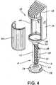
- Fig. 3is a fully exploded view of LED module assembly 8 and a base 26 with protuberance 24. Protuberance 24 is inserted into aperture 22 (shown in Figs. 1 and 2 ) to retain LED module assembly 8 within a housing 34 of luminaire 32 (shown in Figs. 4-6 ).
- Fig. 4is an exploded view of an exemplary embodiment of luminaire 32, which illustrates that LED module assembly 8 may be connected to base 26 by inserting protuberance 24 into aperture 22, as shown in Figs. 1 and 2 .
- LED module assembly 8may be inserted into housing 34 through opening 36.
- Base 26may be securely connected to housing 34 adjacent to opening 36.
- Some embodimentsutilize a housing cover 38 to cover aperture 40 in housing 34.
- External heat sink 42may be connected to the exterior surface of housing 34 at an end opposite opening 36.
- external heat sink 42may be connected to internal heat pipe 18 (shown in Figs. 1 and 2 ). This is done by placing an interior surface of housing 34 that is adjacent to external heat sink 42 in direct contact with heat pipe mating surface 20, which is connected to thermal assembly 19, thus reducing the number of thermal interfaces and improving heat transfer out of the luminaire enclosure.
- internal heat pipe 18is also connected to external heat sink 42 through connection of aperture 22 (shown in Figs. 1 and 2 ) to protuberance 24 on base 26 (shown in Figs. 3 and 4 ), which is connected to housing 34 and thus to external heat sink 42.
- thermal junction 44is created when heat pipe mating surface 20 contacts the interior surface of housing 34.
- the LED module assembly 8may be considered to be in an engaged position relative to housing 34.
- some mechanical forceis applied when the LED module assembly 8 is placed in an engaged position relative to housing 34.
- One embodimentmay include the use of a spring loaded member to achieve some mechanical force between heat pipe mating surface 20 and housing 34.
- heat pipe mating surface 20 and the interior surface of housing 34should have complementary mating surfaces that are generally flat and substantially smooth. In order to ensure easy servicing, appropriate guides should be implemented that orient and seat the heat pipe mating surface 20 relative to housing 34 without any effort required of the service personnel. The orientation feature also provides proper alignment of the LED 10 and the optical elements within the luminaire 32.
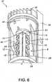
- Fig. 6is a perspective view of one embodiment of luminaire 32, showing LED module assembly 8 in a disengaged position relative to housing 34. In this position, heat pipe mating surface 20 is not in contact with housing 34. This position allows LED module assembly 8 to be serviced without the need for substantial adjustment by service personnel.
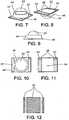
- Fig. 7is a perspective view of an exemplary embodiment of LED 10.
- LED reflector 46is attached to a surface of substrate 48.
- LED lens 50is attached to LED reflector 46 on a surface of LED reflector 46 that opposes the surface of LED reflector 46 that is attached to substrate 48.
- a plurality of electrical contact areas 52are located on the surface of substrate 48 adjacent to LED reflector 46.
- Fig. 8is a rotated perspective view of LED 10, which shows a plurality of electrical contact areas 52 located on the opposite surface of substrate 48 and substantially aligned with electrical contact areas 52 that are adjacent to LED reflector 46.
- the section of the surface of substrate 48 adjacent to electrical contact areas 52 and on the opposite side of substrate 48 from LED reflector 46is referred to as thermal contact area 54.
- Figs. 9-11show side, top, and bottom views, respectively, of LED 10.
- Fig. 12illustrates one embodiment of a solder pad 56 that is used to connect LED 10 to PCB 14.
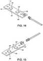
- FIG. 13-16Another embodiment of the present invention, as illustrated in Figs. 13-16 , further improves the conduction path by placing thermal contact area 54 in direct contact with contact pad 16. thus eliminating an additional source of thermal resistance.
- This embodimentutilizes the electrical contact areas 52 on the front side of LED 10 to connect to a PCB 14 (not shown), while providing an electrically neutral thermal transfer area 54 on the back side of LED 10 to mount directly to contact pad 16. Cree XL7090 LEDs, for example, provide such electrical contact areas 52 on the front side of LED 10.
- structure 12is first attached to PCBs 14 and LEDs 10, then coupled to thermal assembly 19 to achieve a direct interface from LED 10 to the heat transfer area.
- This embodimenthas a lower thermal resistance when compared to the same LED 10 mounted to a PCB 14 that is in turn mounted to the thermal assembly 19.
- an LED "die” or “chip,” along with an encapsulant,may be directly mounted to the contact pads 16 with appropriate electrical isolation between the die and chips.
- At least one groove 58is located on the surface of contact pads 16 substantially parallel and opposite at least one electrical contact area 52 on the bottom of LED 10. Grooves 58 are intended to prevent contact between electrical contact areas 52 and contact pad 16 so that LED 10 will not short out.
- Figs. 14 and 15illustrate use of a plurality of LED apertures 60 to allow LED lens 50 and LED reflector 46 to extend through PCB 14 when PCB 14 is connected to electrical contact areas 52 on the surface of substrate 48 adjacent to LED reflector 46.
- Fig. 16is a bottom view of this embodiment showing a plurality of electrical contact areas 52 and thermal contact areas 54 located on the surfaces of substrates 48 opposite the sides of substrates 48 connected to LED reflectors 46.
Landscapes
- Engineering & Computer Science (AREA)
- General Engineering & Computer Science (AREA)
- Physics & Mathematics (AREA)
- Geometry (AREA)
- Arrangement Of Elements, Cooling, Sealing, Or The Like Of Lighting Devices (AREA)
- Non-Portable Lighting Devices Or Systems Thereof (AREA)
Description
- This invention relates to thermal management for light emitting diode based lighting systems.
- The purpose of a lamp is to convert electrical energy to visible light. There are a variety of lamps used in the lighting industry. Some examples are high intensity discharge ("HID"), fluorescent, incandescent, and light emitting diode ("LED"). Each of these lamps emits and dissipates energy in the form of radiant energy and heat in various amounts. For example, a 400 watt metal halide lamp converts approximately 112 watts to visible energy, 20 watts to UV energy, 72 watts to IR energy, while the remaining 200 watts of energy is converted to heat and dissipated to the surrounding environment via conduction through the lamp base and convection off the glass envelope. An LED used for lighting or illumination converts electrical energy to light in a fundamentally different way than HID, fluorescent, and incandescent lamps, resulting in very little radiant energy outside the visible spectrum. The bulk of the energy lost in the conversion process is dissipated as thermal energy through the LED chip and the mechanical structure that surrounds it. The energy conversions (percent of electrical energy input) for the aforementioned light sources are shown in the Table 1.
- An example of an automotive lighting assembly cooling system is shown in
US 2004/0213016 . Such a lighting assembly includes a heat pipe with an evaporation area proximate to a heat generating component, such as an LED, and a condensing area located remote from the evaporation area. Evaporation of fluid within the heat pipe transfers heat away from the heat generating component. The efficiency of the cooling system in one embodiment shown inUS 2004/0213016 is increased by including fins associated with the condensing area and placing the fins in an area where air flow external to a moving vehicle assists in cooling the fins.Table 1: Energy conversion of various light sources (percent of electrical energy input) HID Fluorescent Incandescent LED Visible 28 23 5 12 UV 5 0 0 0 IR 18 36 90 0 Total Radiant 51 59 95 12 Conduction & Convection 49 41 5 88 - As shown by Table 1, a significant amount of energy is converted to heat by the lamp. In any luminaire design, the heat generated by the lamp may cause problems related to the basic function of the lamp and luminaire. Benefits associated with effective removal of thermal energy from within the luminaire include improved luminaire life, smaller (lower cost) package sizes, and improved lumen output in some lamp types, such as fluorescent and LED. An additional benefit of removing heat from the luminaire is that the luminaire may then be operated in a higher ambient temperature environment without compromising luminaire life or performance. In the case of an LED, better thermal management allows the LED to be driven at higher power levels while mitigating the negative effects on life and light output normally associated with higher power input levels.
- There are three mechanisms for dissipating thermal energy from an LED: conduction, convection, and radiation. Conduction occurs when LED chips, the mechanical structure of the LEDs, the LED mounting structure (such as printed circuit boards), and the luminaire housing are placed in physical contact with one another. Physical contact with the LEDs is generally optimized to provide electrical power and mechanical support Traditional means of providing electrical and mechanical contact between LEDs and the luminaire provide poor means of conduction between the LEDs and external luminaire surfaces (such as die cast housing). In addition, the location of LEDs is often determined by the desired optical performance of the luminaire. This often necessitates mounting LEDs a large distance from effective heat dissipating structures of the luminaire, which further impedes the conductive transfer of heat out of the luminaire envelope by creating a longer thermal path, introducing additional thermal interfaces, introducing materials with a lower thermal conductivity, or a combination thereof. A further disadvantage of using a thermally conductive structure within the luminaire envelope is that it allows dissipation of heat into the enclosure, which is generally sealed. This effectively raises the ambient temperature of the air surrounding the LEDs, thus compounding thermal related failures.
- Convection occurs at any surface exposed to air, but may be limited by the amount of air movement near the emitting surface, the surface area available for dissipation, and the difference between the temperature of the emitting surface and the surrounding air. In many cases, the luminaire is enclosed further restricting airflow around the LEDs. In such an enclosure, heat generated by the LEDs is transferred by convection to the air within the enclosure, but cannot escape the boundaries of the enclosure. Although the LED itself does not contribute significant amounts of heat due to its small size, the components that are used to mount the LEDs are often large, thus allowing greater dissipation to the air within the enclosure by convection. As a result, the air within the enclosure experiences a build up of heat, which elevates lamp and luminaire temperatures and may lead to heat related failures. For example, in luminaires with electronic ballasts and components, excessive heat can shorten the life of the electronic components, resulting in premature failure of the lighting system.
- Radiation is the movement of energy from one point to another via electromagnetic propagation. Much of the radiant energy escapes the luminaire through the clear optical elements (light emitting zones, lenses, etc) and reflectors, which are designed to redirect the radiant energy (visible light in particular) out of the luminaire according to the needs of the application. The radiant energy that does not escape through the lenses is absorbed by the various materials within the luminaire and converted into heat.
- Of these three modes of thermal transfer, providing an effective conduction path often allows the greatest amount of controlled heat removal from within a luminaire. This is especially pertinent for luminaires that are enclosed to meet the requirements of the application (weather-proofing, concealing electrical components, safety, etc). Of particular importance is the need to optimize the thermal path to allow a low thermal resistance from the LED heat source to the dissipating surface on the exterior of the luminaire, while minimizing the cross-sectional area of the thermal path along the interior of the luminaire enclosure. A heat pipe is one mechanism that has been used to remove heat under these conditions.
- A heat pipe is a tube, usually comprised of metal, that is evacuated and sealed with a small amount of fluid inside. Because the tube is sealed and evacuated, the working fluid changes from liquid to vapor at a relatively low temperature compared to the boiling point of that fluid at normal atmospheric pressure. The choice of fluid and internal pressure determine the temperature at which vaporization occurs. When a heat source is applied, the fluid will vaporize and uniformly fill the tube, resulting in a state of equilibrium where the fluid exists in both liquid and vapor form based on the amount of heat applied. If there is a location on the tube wall that is cooler than the area where the heat source is applied, the vapor will condense at that location. When fluid changes state from vapor to liquid, large amounts of energy are released.
- With the addition of a special structure inside the tube, called a capillary structure, the fluid in liquid form will readily return to the spot where the heat source is applied via capillary action. The addition of the capillary structure within the tube creates a double-phase change convective thermal transfer loop that achieves a high thermal transfer coefficient over relatively large distances and small cross-sectional areas compared to what can be achieved with other thermal transfer structures. A heat pipe thus allows a relatively small heat producing area to be coupled to a large heat-dissipating surface that is far away from the heat source using a relatively small cross-sectional area structure to couple to the heat source and transfer the heat to the larger dissipating region. Such an arrangement is advantageous when the heat source is located inside an enclosed cavity with limited surface area or complex geometry for coupling to and dissipating heat.
- In addition to the issue of thermal management, two compounding challenges have limited widespread adoption of LEDs for general illumination: concern over availability of LEDs as the technology changes and the prohibitive expense associated with LED replacement. The concern over LED availability is due to the fact that LEDs are very new to the market within the historical perspective of HID and fluorescent light source availability. Because LED technology is new and rapidly developing, the form factor of individual LEDs and the efficacy of LEDs change on a yearly basis. LEDs that were introduced as little as five years ago are no longer available today. LEDs that were introduced a year ago have efficacy improvement of 20 to 50%. This means that an owner, performing the simple act of purchasing replacement LEDs, will have to reconsider the impact on light levels, type of optics used, LED drivers, and thermal performance of the system. Essentially, the owner is required to perform an entire re-evaluation of the lighting installation, which is a considerable expense. Alternatively, an owner may obtain purchase agreements with LED manufacturers that ensure future availability of LEDs as originally specified. This approach, however, defeats the future energy savings potential of efficacy improvements in LED technology. These considerations are the root causes of significant concern on the part of facility owners and operators when considering LED based lighting systems. Therefore, it is desirable to have a solution that allows for forward compatibility of LED changes without impact to the form factor, thermal, or optical performance of the luminaire.
- As to the concern over the expense associated with LED replacement, it is generally accepted that properly designed LED light sources within luminaires will have a lifetime of 50,000 hours. This may seem like a long time to people unfamiliar with luminaire construction, or those accustomed to residential lighting systems. A lifetime of 50,000 hours, however, is not exceptional within the general lighting industry as HID and fluorescent light sources with typical lifetimes of 20,000 to 100,000 hours have been used for decades. Furthermore, while these light sources generally provide longer life, it is desirable that they are serviceable in the event of a failure because the installed lifetime of luminaires greatly exceed the lifetime of even a 100,000 hour light source, and thus the thermal path should be able to be engaged and disengaged in a highly repeatable method with minimal introduction of thermal resistances.
- Accordingly, there is a need for an LED based lighting system that includes an optimized conduction path and dissipation area to significantly reduce the amount of heat transferred from the LEDs to the interior of the enclosure, thereby allowing LED luminaires to operate in a higher ambient temperature environment without compromising luminaire life or performance. Additionally, there is a need for LED based lighting systems that allow for forward compatibility of LED changes without impact to the form factor, thermal, or optical performance of the luminaire. Finally, there is a need for LED based lighting systems that provide for LED replacement with minimal introduction of thermal resistances into the thermal path by ensuring that the thermal path engages and disengages in a highly repeatable manner.
- In an exemplary embodiment of the present invention, a lighting apparatus comprises an LED module assembly which in turn comprises a heat pipe with an exterior surface which is connected to at least one contact pad, where this combination forms a thermal assembly. The LED module assembly further comprises at least one light emitting diode coupled to the contact pad. The heat pipe comprises a first end and a second end, wherein the first end of the heat pipe is coupled to a heat pipe mating surface. The lighting apparatus is characterised in that it comprises a luminaire housing. An inner surface of the luminaire housing comprises a housing mating surface, and the heat pipe mating surface is configured to contact and releasably mate with the housing mating surface to define a thermal junction. The lighting apparatus is further characterised in that it comprises a luminaire base, wherein the luminaire base is coupled to the second end of the heat pipe and coupled to the luminaire housing wherein the first end and the second end of the heat pipe are enclosed by the coupled luminaire housing and the luminaire base.
- In some embodiments, an LED driver may be connected in close proximity to the thermal assembly and may be a PWM dimming driver.
- In certain embodiments, the light emitting diode comprises an individual LED, an LED chip, or an LED die mounted to a printed circuit board coupled to the contact pad. In other embodiments, the light emitting diode comprises a printed circuit board coupled to an individual LED, an LED chip, or an LED die mounted directly to the surface of the contact pad. In some embodiments where the light emitting diode is mounted directly to the contact pad, the surface of the contact pad has at least one groove substantially parallel and opposite at least one electrical contact area on the surface of the light emitting diode to prevent contact between the electrical contact area and the contact pad.
- In certain embodiments, the contact pad and the light emitting diode are dimensioned to have substantially similar surface areas. In other embodiments, the contact pad is dimensioned to accommodate a plurality of light emitting diodes.
- In certain embodiments, a thermal junction is located between the heat pipe mating surface and an interior surface of a luminaire housing adjacent to an external heat sink. Some embodiments include a member attached to the luminaire housing that adjusts the position of the LED module assembly with respect to the housing and configured to apply mechanical force to the thermal junction when the heat pipe surface contacts the interior surface of the housing. In other embodiments, the member may be a spring loaded latch engaging and disengaging the LED module assembly at the thermal junction. Other embodiments are described and apparent from the further description of the invention below.
Fig. 1 is a perspective view of an exemplary embodiment of an LED module assembly according to the present invention.Fig. 2 is a partially exploded view of the LED module assembly shown inFig. 1 .Fig. 3 is a fully exploded view of LED module assembly shown inFig. 1 .Fig. 4 is an exploded view illustrating how the LED module assembly shown inFig. 1 is connected to a luminaire housing.Fig. 5 is a partial perspective view of a fully assembled luminaire, with the LED module assembly shown inFig. 1 in an engaged position relative to a luminaire housing.Fig. 6 is a partial perspective view of a fully assembled luminaire, with the LED module assembly shown inFig. 1 in a disengaged position relative to a luminaire housing.Fig. 7 is a perspective view of an exemplary embodiment of an LED.Fig. 8 is a rotated perspective view of the LED shown inFig. 7 .Fig. 9 is a side view of the LED shown inFig. 7 .Fig..10 is a top view of the LED shown inFig. 7 .Fig 11 is a bottom view of the LED shown inFig. 7 .Fig. 12 is a top view of an exemplary embodiment of a solder pad. which is used to connect to the LED shown inFig. 7 .Fig. 13 is a side view illustrating how the LED shown inFig. 7 may be directly connected to a thermal assembly.Fig. 14 is a perspective view illustrating how the LED shown inFig. 7 may be connected to a printed circuit board ("PCB").Fig. 15 is a rotated view of the LED and PCB shown inFig. 14 .Fig. 16 is a rotated view showing the underside of the LED and PCB shown inFig. 14 .- An embodiment of the present invention proposes to reduce the thermal issues associated with lamp energy dissipation by implementing an optimized conduction path from the lamp to the exterior of the luminaire, away from thermally sensitive components, through the use of heat pipes integrated into an LED module assembly and luminaire. One advantage of using a heat pipe for thermal management is that it is a passive device, requiring no electrical energy or temperature sensing circuitry to operate. In such an embodiment, a significant reduction in thermal transfer to the interior of the enclosure may be implemented, while allowing maximum dissipation of energy from the LEDs.
- As illustrated in
Fig. 1 , anLED module assembly 8 according to one exemplary embodiment of the present invention includes a plurality ofLEDs 10 surrounded by astructure 12. EachLED 10 is mounted to a surface of a printed circuit board ("PCB") 14. The surfaces ofPCB 14 opposite the surfaces coupled toLEDs 10 are coupled to a plurality of thermal transfer interfaces ("contact pads") 16 that are in turn coupled tointernal heat pipe 18. The structure including the connection ofcontact pads 16 tointernal heat pipe 18 is referred to asthermal assembly 19. One end ofthermal assembly 19 is connected to a heatpipe mating surface 20. The opposing end ofthermal assembly 19 contains anaperture 22 designed to receiveprotuberance 24 located onbase 26, as shown inFig. 3 .LEDs 10,PCB 14, andstructure 12 are collectively referred to asLED mounting structure 28. - In these embodiments,
structure 12 substantially coversLEDs 10,PCBs 14, andthermal assembly 19 to ensure that the heat pipe is the main conduit for flow of thermal energy. In one embodiment,structure 12 is a material with a low thermal conductivity. In another embodiment,structure 12 is a thermally insulating material. - In certain embodiments,
contact pad 16 andLED 10 are dimensioned to have substantially similar surface areas. In other embodiments,contact pad 16 is dimensioned to accommodate a plurality ofLEDs 10, thus allowing greater flexibility inpositioning LEDs 10 as needed to meet optical performance requirements. - In certain embodiments of the present invention, LED replacement is incorporated into the present invention to allow for forward compatibility of the LED lamp and to allow replacement
LED module assemblies 8 to be manufactured in a manner that does not affect the optical or thermal performance of the original luminaire 32 (shown inFigs. 4-6 ) and itsLED module assembly 8 as the replacement unit will haveLEDs 10 in the same physical location relative to the optics, and also incorporate the same thermal mechanism (internal heat pipe 18). Withhigher efficacy LEDs 10 driven in a dimmed state in the same physical location, optical performance equivalent to theoriginal luminaire 32 andLED module assembly 8 is achieved. Fig. 2 is a rotated and partially exploded view ofLED module assembly 8 and includingLED driver 30 that is connected to acontact pad 16 adjacent to twoLED mounting structures 28. In one embodiment,LEDs 10 andLED driver 30 are serviceable as a singleLED module assembly 8. Anexemplary LED driver 30 has a lifetime of 50,000 hours, which is complementary to the lifetime ofLEDs 10, and thus replacement of a singleLED module assembly 8 containing bothLEDs 10 andLED driver 30 will minimize service costs. Moreover, anLED module assembly 8 containing bothLEDs 10 andLED driver 30 provides for forward compatibility of the LED lamp. By integratingLED driver 30 withLEDs 10 in a single replacementLED module assembly 8,LED driver 30 may be appropriately designed forfuture LEDs 10 with improved efficacy. Several approaches are available to enable this forward compatibility of driver and LEDs.- In one embodiment of the invention,
LED driver 30 may be designed as a PWM dimming driver, thus allowingLEDs 10 to be dimmed to factory specified levels that match the original LED/driver combination. One advantage of this approach is thatLED driver 30 does not change over time, rather only the "dim level" changes. In this embodiment, there is no consideration regarding form factor changes for the luminaire/LED lamp manufacturer. In another embodiment, anon-dimming LED driver 30 is redesigned periodically to accommodate efficacy improvements inLEDs 10. - In some embodiments,
LED driver 30 may be placed in close proximity tothermal assembly 19 becauseLEDs 10 and the thermal conduction path are isolated. In other embodiments, theLED driver 30 may be directly attached to thethermal assembly 19. Fig. 3 is a fully exploded view ofLED module assembly 8 and a base 26 withprotuberance 24.Protuberance 24 is inserted into aperture 22 (shown inFigs. 1 and2 ) to retainLED module assembly 8 within ahousing 34 of luminaire 32 (shown inFigs. 4-6 ).Fig. 4 is an exploded view of an exemplary embodiment ofluminaire 32, which illustrates thatLED module assembly 8 may be connected to base 26 by insertingprotuberance 24 intoaperture 22, as shown inFigs. 1 and2 . In this embodiment,LED module assembly 8 may be inserted intohousing 34 throughopening 36.Base 26 may be securely connected tohousing 34 adjacent toopening 36. Some embodiments utilize ahousing cover 38 to coveraperture 40 inhousing 34.External heat sink 42 may be connected to the exterior surface ofhousing 34 at an end opposite opening 36.- In another embodiment, as illustrated in
Fig. 5 , afterLED module assembly 8 is inserted throughopening 36,external heat sink 42 may be connected to internal heat pipe 18 (shown inFigs. 1 and2 ). This is done by placing an interior surface ofhousing 34 that is adjacent toexternal heat sink 42 in direct contact with heatpipe mating surface 20, which is connected tothermal assembly 19, thus reducing the number of thermal interfaces and improving heat transfer out of the luminaire enclosure. In these embodiments,internal heat pipe 18 is also connected toexternal heat sink 42 through connection of aperture 22 (shown inFigs. 1 and2 ) toprotuberance 24 on base 26 (shown inFigs. 3 and4 ), which is connected tohousing 34 and thus toexternal heat sink 42. - In these embodiments,
thermal junction 44 is created when heatpipe mating surface 20 contacts the interior surface ofhousing 34. When heatpipe mating surface 20contacts housing 34, theLED module assembly 8 may be considered to be in an engaged position relative tohousing 34. In some embodiments, to reduce thermal resistance ofthermal junction 44, some mechanical force is applied when theLED module assembly 8 is placed in an engaged position relative tohousing 34. One embodiment may include the use of a spring loaded member to achieve some mechanical force between heatpipe mating surface 20 andhousing 34. To further minimize thermal resistance ofthermal junction 44, heatpipe mating surface 20 and the interior surface ofhousing 34 should have complementary mating surfaces that are generally flat and substantially smooth. In order to ensure easy servicing, appropriate guides should be implemented that orient and seat the heatpipe mating surface 20 relative tohousing 34 without any effort required of the service personnel. The orientation feature also provides proper alignment of theLED 10 and the optical elements within theluminaire 32. Fig. 6 is a perspective view of one embodiment ofluminaire 32, showingLED module assembly 8 in a disengaged position relative tohousing 34. In this position, heatpipe mating surface 20 is not in contact withhousing 34. This position allowsLED module assembly 8 to be serviced without the need for substantial adjustment by service personnel.Fig. 7 is a perspective view of an exemplary embodiment ofLED 10.LED reflector 46 is attached to a surface ofsubstrate 48.LED lens 50 is attached toLED reflector 46 on a surface ofLED reflector 46 that opposes the surface ofLED reflector 46 that is attached tosubstrate 48. A plurality ofelectrical contact areas 52 are located on the surface ofsubstrate 48 adjacent toLED reflector 46.Fig. 8 is a rotated perspective view ofLED 10, which shows a plurality ofelectrical contact areas 52 located on the opposite surface ofsubstrate 48 and substantially aligned withelectrical contact areas 52 that are adjacent toLED reflector 46. The section of the surface ofsubstrate 48 adjacent toelectrical contact areas 52 and on the opposite side ofsubstrate 48 fromLED reflector 46 is referred to asthermal contact area 54.Figs. 9-11 show side, top, and bottom views, respectively, ofLED 10.Fig. 12 illustrates one embodiment of asolder pad 56 that is used to connectLED 10 toPCB 14.- Another embodiment of the present invention, as illustrated in
Figs. 13-16 , further improves the conduction path by placingthermal contact area 54 in direct contact withcontact pad 16. thus eliminating an additional source of thermal resistance. This embodiment utilizes theelectrical contact areas 52 on the front side ofLED 10 to connect to a PCB 14 (not shown), while providing an electrically neutralthermal transfer area 54 on the back side ofLED 10 to mount directly tocontact pad 16. Cree XL7090 LEDs, for example, provide suchelectrical contact areas 52 on the front side ofLED 10. In some embodiments,structure 12 is first attached toPCBs 14 andLEDs 10, then coupled tothermal assembly 19 to achieve a direct interface fromLED 10 to the heat transfer area. This embodiment has a lower thermal resistance when compared to thesame LED 10 mounted to aPCB 14 that is in turn mounted to thethermal assembly 19. In another specific embodiment, an LED "die" or "chip," along with an encapsulant, may be directly mounted to thecontact pads 16 with appropriate electrical isolation between the die and chips. - As shown in
Fig. 13 , at least onegroove 58 is located on the surface ofcontact pads 16 substantially parallel and opposite at least oneelectrical contact area 52 on the bottom ofLED 10.Grooves 58 are intended to prevent contact betweenelectrical contact areas 52 andcontact pad 16 so thatLED 10 will not short out. Figs. 14 and 15 illustrate use of a plurality ofLED apertures 60 to allowLED lens 50 andLED reflector 46 to extend throughPCB 14 whenPCB 14 is connected toelectrical contact areas 52 on the surface ofsubstrate 48 adjacent toLED reflector 46.Fig. 16 is a bottom view of this embodiment showing a plurality ofelectrical contact areas 52 andthermal contact areas 54 located on the surfaces ofsubstrates 48 opposite the sides ofsubstrates 48 connected toLED reflectors 46.- The foregoing description of the exemplary embodiments of the invention has been presented only for the purposes of illustration and description and is not intended to be exhaustive or to limit the invention to the precise forms described. Many modifications and variations are possible in light of the above teaching. The embodiments were chosen and described in order to explain the principles of the invention and their practical application so as to enable others skilled in the art to utilize the invention and various embodiments and with various modifications as are suited to the particular use contemplated. Alternative embodiments will become apparent to those skilled in the art to which the present invention pertains without departing from its scope.
Claims (12)
- A lighting apparatus comprising:an LED module assembly (8) comprising:a thermal assembly (19) comprising a heat pipe (18) and contact pad (16) coupled to an exterior surface of the heat pipe (18);at least one light emitting diode (10) coupled to the contact pad (16);the heat pipe (18) comprising a first end and a second end, wherein the first end of the heat pipe (18) is coupled to a heat pipe mating surface (20),the lighting apparatus beingcharacterised in that it comprises:wherein the first end and the second end of the heat pipe (18) are enclosed by the coupled luminaire housing (34) and the luminaire base (26).a luminaire housing (34), wherein an inner surface of the luminaire housing (34) comprises a housing mating surface, and wherein the heat pipe mating surface (20) is configured to contact and releasably mate with the housing mating surface to define a thermal junction (44); anda luminaire base (26), wherein the luminaire base (26) is coupled to the second end of the heat pipe (18) and coupled to the luminaire housing (34),
- The lighting apparatus of Claim 1, wherein the LED module assembly (8) further comprises an LED driver(30) connected in close proximity to the thermal assembly (19).
- The lighting apparatus of Claim 2, wherein the LED driver (30) is a PWM dimming driver.
- The lighting apparatus of Claim 1, wherein the at least one light emitting diode (10) comprises one of an individual LED, an LED chip, or an LED die.
- The lighting apparatus of Claim 1, wherein the at least one light emitting diode (10) Is coupled to the contact pad (16) by mounting the at least one light emitting diode (10) to a printed circuit board (14) that is attached to the contact pad (16).
- The lighting apparatus of Claim 1, wherein the at least one light emitting diode(10) is mounted directly to the surface of the contact pad (16).
- The lighting apparatus of Claim 6, wherein the contact pad (16) has at least one groove located on a surface of the contact pad (16) substantially parallel and opposite at least one electrical contact area on a surface of the at least one light emitting diode (10) to prevent contact between the electrical contact area and the contact pad (16).
- The lighting apparatus of Claim 1, wherein the contact pad (16) is dimensioned to have a substantially similar surface area as one of the at least one light emitting diode (10).
- The lighting apparatus of Claim 1, wherein the contact pad (16) is dimensioned to accommodate a plurality of light emitting diodes (10).
- A lighting apparatus according to any of Claims 1 to 5 further comprising
an external heat sink (42) adjacent an end of the luminaire housing (34); and
a member attached to the luminaire housing (34) that adjusts a position of the LED module assembly (8) with respect to the luminaire housing (34) and configured to apply mechanical force to the thermal junction (44) when the heat pipe mating surface (20) contacts the inner surface of the luminaire housing (34),
wherein the thermal junction (44) of the LED module assembly (8) is defined between the heat pipe mating surface and the inner surface of the luminaire housing (34) near the end of the luminaire housing (34). - The lighting apparatus of Claim 10, wherein the member is a spring loaded latch for engaging and disengaging the LED module assembly (8) at the thermal junction (44).
- The apparatus of Claim 10, wherein the LED module assembly (8) comprises a heat pipe (18) and contact pad (16) integrated as single structure.
Applications Claiming Priority (2)
| Application Number | Priority Date | Filing Date | Title |
|---|---|---|---|
| US87209106P | 2006-12-01 | 2006-12-01 | |
| PCT/US2007/085875WO2008070519A2 (en) | 2006-12-01 | 2007-11-29 | Systems and methods for thermal management of lamps and luminaires using led sources |
Publications (3)
| Publication Number | Publication Date |
|---|---|
| EP2103191A2 EP2103191A2 (en) | 2009-09-23 |
| EP2103191A4 EP2103191A4 (en) | 2013-04-10 |
| EP2103191B1true EP2103191B1 (en) | 2016-04-27 |
Family
ID=39492993
Family Applications (1)
| Application Number | Title | Priority Date | Filing Date |
|---|---|---|---|
| EP07864872.2ANot-in-forceEP2103191B1 (en) | 2006-12-01 | 2007-11-29 | Systems and methods for thermal management of lamps and luminaires using led sources |
Country Status (4)
| Country | Link |
|---|---|
| US (1) | US7784971B2 (en) |
| EP (1) | EP2103191B1 (en) |
| CA (1) | CA2612973C (en) |
| WO (1) | WO2008070519A2 (en) |
Families Citing this family (54)
| Publication number | Priority date | Publication date | Assignee | Title |
|---|---|---|---|---|
| EP2103191B1 (en) | 2006-12-01 | 2016-04-27 | ABL IP Holding LLC | Systems and methods for thermal management of lamps and luminaires using led sources |
| US7568817B2 (en)* | 2007-06-27 | 2009-08-04 | Fu Zhun Precision Industry (Shen Zhen) Co., Ltd. | LED lamp |
| US7503790B2 (en)* | 2007-07-03 | 2009-03-17 | Rockwell Automation Technologies, Inc. | Industrial automation input output module with elastomeric sealing |
| US7744250B2 (en)* | 2007-07-12 | 2010-06-29 | Fu Zhun Precision Industry (Shen Zhen) Co., Ltd. | LED lamp with a heat dissipation device |
| CN101349412A (en)* | 2007-07-18 | 2009-01-21 | 富准精密工业(深圳)有限公司 | LED lamp |
| WO2009065106A2 (en)* | 2007-11-15 | 2009-05-22 | Starkey Carl R | Light system and method to thermally manage an led lighting system |
| CN101435567B (en)* | 2007-11-16 | 2010-11-10 | 富准精密工业(深圳)有限公司 | LED light fitting |
| CN101435566A (en)* | 2007-11-16 | 2009-05-20 | 富准精密工业(深圳)有限公司 | LED light fitting |
| US8033685B2 (en)* | 2008-03-27 | 2011-10-11 | Mcgehee Michael Eugene | LED luminaire |
| US7744251B2 (en)* | 2008-04-10 | 2010-06-29 | Fu Zhun Precision Industry (Shen Zhen) Co., Ltd. | LED lamp having a sealed structure |
| US7637637B2 (en)* | 2008-04-16 | 2009-12-29 | Fu Zhun Precision Industry (Shen Zhen) Co., Ltd. | Outdoor LED lamp assembly |
| US8092032B2 (en)* | 2008-04-24 | 2012-01-10 | King Luminaire Co., Inc. | LED lighting array assembly |
| US20090268453A1 (en)* | 2008-04-24 | 2009-10-29 | King Luminarie Co., Inc. | LED baffle assembly |
| US8011809B2 (en)* | 2008-05-16 | 2011-09-06 | Yun Chang Liao | Light-emitting diode module with heat dissipating structure and lamp with light-emitting diode module |
| US7837358B2 (en)* | 2008-05-16 | 2010-11-23 | Liao yun-chang | Light-emitting diode module with heat dissipating structure |
| CN102047028A (en)* | 2008-05-29 | 2011-05-04 | 罗姆股份有限公司 | Led lamp |
| CN101769517A (en)* | 2008-12-27 | 2010-07-07 | 富准精密工业(深圳)有限公司 | Light-emitting module and light-emitting diode lamp applying same |
| US8576406B1 (en) | 2009-02-25 | 2013-11-05 | Physical Optics Corporation | Luminaire illumination system and method |
| US8419249B2 (en)* | 2009-04-15 | 2013-04-16 | Stanley Electric Co., Ltd. | Liquid-cooled LED lighting device |
| US7810968B1 (en)* | 2009-05-15 | 2010-10-12 | Koninklijke Philips Electronics N.V. | LED unit for installation in a post-top luminaire |
| DE102009058309A1 (en)* | 2009-07-09 | 2011-01-13 | Siteco Beleuchtungstechnik Gmbh | LED lights use |
| US8098433B2 (en)* | 2009-12-11 | 2012-01-17 | Solatube International, Inc. | Direct and indirect light diffusing devices and methods |
| US8568011B2 (en) | 2009-08-20 | 2013-10-29 | Solatube International, Inc. | Daylighting devices with auxiliary lighting system and light turning features |
| CN201487724U (en)* | 2009-09-03 | 2010-05-26 | 浙江纳桑电子科技有限公司 | High-power LED street lamp |
| USD617493S1 (en)* | 2009-10-06 | 2010-06-08 | Hubbell Incorporated | Flow-through LED carrier for luminaire |
| CN101761806B (en)* | 2009-12-11 | 2011-09-21 | 鸿富锦精密工业(深圳)有限公司 | LED light with replaceable lens |
| US20110149567A1 (en)* | 2009-12-18 | 2011-06-23 | Zhirong Lee | High Power LED Street Light Structure |
| JP5421799B2 (en)* | 2010-01-18 | 2014-02-19 | パナソニック株式会社 | LED unit |
| US8601757B2 (en) | 2010-05-27 | 2013-12-10 | Solatube International, Inc. | Thermally insulating fenestration devices and methods |
| AU2010202801A1 (en)* | 2010-07-05 | 2012-01-19 | Neobulb Technologies, Inc. | Light-emitting diode illumination platform |
| US8550650B1 (en) | 2010-08-10 | 2013-10-08 | Patrick McGinty | Lighted helmet with heat pipe assembly |
| US9249952B2 (en)* | 2010-11-05 | 2016-02-02 | Cree, Inc. | Multi-configurable, high luminous output light fixture systems, devices and methods |
| USD672906S1 (en)* | 2011-02-25 | 2012-12-18 | Lg Innotek Co., Ltd. | Head of street lamp |
| US20120313547A1 (en)* | 2011-06-10 | 2012-12-13 | Honeywell International Inc. | Aircraft led landing or taxi lights with thermal management |
| US20130044476A1 (en)* | 2011-08-17 | 2013-02-21 | Eric Bretschneider | Lighting unit with heat-dissipating circuit board |
| CN104081115B (en) | 2011-11-30 | 2016-11-09 | 索乐图国际公司 | Daylight collection system and method |
| US20130265780A1 (en)* | 2012-04-05 | 2013-10-10 | Black & Decker Inc. | Light module and light stand assembly |
| US8974077B2 (en) | 2012-07-30 | 2015-03-10 | Ultravision Technologies, Llc | Heat sink for LED light source |
| US9921397B2 (en) | 2012-12-11 | 2018-03-20 | Solatube International, Inc. | Daylight collectors with thermal control |
| US8982467B2 (en) | 2012-12-11 | 2015-03-17 | Solatube International, Inc. | High aspect ratio daylight collectors |
| US8919994B2 (en)* | 2012-12-12 | 2014-12-30 | Randal L. Wimberly | Illumination system and lamp utilizing directionalized LEDs |
| WO2015066069A1 (en) | 2013-10-28 | 2015-05-07 | Next Lighting Corp. | Linear lamp replacement |
| US9195281B2 (en) | 2013-12-31 | 2015-11-24 | Ultravision Technologies, Llc | System and method for a modular multi-panel display |
| US20150192261A1 (en)* | 2014-01-08 | 2015-07-09 | Richard L. May | Linear Lighting Apparatus |
| US9835301B2 (en)* | 2014-07-01 | 2017-12-05 | Abl Ip Holding Llc | Optical systems and methods for pole luminaires |
| US9765956B2 (en)* | 2014-08-04 | 2017-09-19 | Spring City Electrical Manufacturing Company | LED luminaire light fixture for a lamppost |
| CN105371214A (en)* | 2015-12-16 | 2016-03-02 | 广州共铸科技股份有限公司 | LED automobile head lamp |
| USD841849S1 (en) | 2016-10-31 | 2019-02-26 | Delta T, Llc | Handheld light assembly with battery pack |
| RU2707082C2 (en)* | 2017-08-08 | 2019-11-22 | Денис Геннадьевич Дроздов | Led lamp (embodiments) for lighting of agricultural crops |
| RU2699013C2 (en)* | 2017-10-27 | 2019-09-03 | Денис Геннадьевич Дроздов | Led lamp and method of lighting agricultural crops |
| US10344930B1 (en)* | 2018-04-30 | 2019-07-09 | Feit Electric Company, Inc. | Flame lamp |
| EP3875838B1 (en)* | 2020-03-06 | 2023-09-20 | Lumileds Holding B.V. | Lighting device with light guide |
| RU2745978C1 (en)* | 2020-03-15 | 2021-04-05 | Денис Геннадьевич Дроздов | Housing-radiator of the led lamp |
| US11448388B2 (en)* | 2020-05-01 | 2022-09-20 | Exposure Illumination Architects, Inc. | Vertical illumination device with lamp modules having nano-optical lenses structure with light source pre-configured to uniformly illuminate horizontal areas below |
Family Cites Families (22)
| Publication number | Priority date | Publication date | Assignee | Title |
|---|---|---|---|---|
| US4081023A (en)* | 1976-11-26 | 1978-03-28 | Grumman Aerospace Corporation | Heat pipes to use heat from light fixtures |
| US4411516A (en)* | 1981-04-24 | 1983-10-25 | Canon Kabushiki Kaisha | Original illumination apparatus |
| ATE47624T1 (en)* | 1984-11-15 | 1989-11-15 | Japan Traffic Manage Tech Ass | SIGNAL LIGHT UNIT WITH HEAT DISSIPATION. |
| US4733335A (en)* | 1984-12-28 | 1988-03-22 | Koito Manufacturing Co., Ltd. | Vehicular lamp |
| US6517221B1 (en)* | 1999-06-18 | 2003-02-11 | Ciena Corporation | Heat pipe heat sink for cooling a laser diode |
| US6917637B2 (en)* | 2001-10-12 | 2005-07-12 | Fuji Photo Film Co., Ltd. | Cooling device for laser diodes |
| US6586890B2 (en)* | 2001-12-05 | 2003-07-01 | Koninklijke Philips Electronics N.V. | LED driver circuit with PWM output |
| US7048412B2 (en)* | 2002-06-10 | 2006-05-23 | Lumileds Lighting U.S., Llc | Axial LED source |
| US6911915B2 (en)* | 2002-09-04 | 2005-06-28 | Leotek Electronics Corporation | Compact light emitting diode retrofit lamp and method for traffic signal lights |
| WO2004071143A1 (en)* | 2003-02-07 | 2004-08-19 | Matsushita Electric Industrial Co., Ltd. | Socket for led light source and lighting system using the socket |
| JP2004265986A (en)* | 2003-02-28 | 2004-09-24 | Citizen Electronics Co Ltd | High brightness light emitting element, light emitting device using the same, and method of manufacturing high brightness light emitting element |
| US6910794B2 (en)* | 2003-04-25 | 2005-06-28 | Guide Corporation | Automotive lighting assembly cooling system |
| US6976769B2 (en)* | 2003-06-11 | 2005-12-20 | Cool Options, Inc. | Light-emitting diode reflector assembly having a heat pipe |
| US7126290B2 (en)* | 2004-02-02 | 2006-10-24 | Radiant Power Corp. | Light dimmer for LED and incandescent lamps |
| US7246921B2 (en)* | 2004-02-03 | 2007-07-24 | Illumitech, Inc. | Back-reflecting LED light source |
| US7095110B2 (en)* | 2004-05-21 | 2006-08-22 | Gelcore, Llc | Light emitting diode apparatuses with heat pipes for thermal management |
| TWI263008B (en)* | 2004-06-30 | 2006-10-01 | Ind Tech Res Inst | LED lamp |
| DE102005063433B4 (en)* | 2004-10-29 | 2009-11-26 | Lg Display Co., Ltd. | Backlight unit and liquid crystal display device |
| KR100671545B1 (en)* | 2005-07-01 | 2007-01-19 | 삼성전자주식회사 | LED array module |
| US7431475B2 (en)* | 2005-07-22 | 2008-10-07 | Sony Corporation | Radiator for light emitting unit, and backlight device |
| US7560742B2 (en)* | 2005-11-28 | 2009-07-14 | Magna International Inc. | Semiconductor-based lighting systems and lighting system components for automotive use |
| EP2103191B1 (en) | 2006-12-01 | 2016-04-27 | ABL IP Holding LLC | Systems and methods for thermal management of lamps and luminaires using led sources |
- 2007
- 2007-11-29EPEP07864872.2Apatent/EP2103191B1/ennot_activeNot-in-force
- 2007-11-29WOPCT/US2007/085875patent/WO2008070519A2/enactiveApplication Filing
- 2007-11-29USUS11/947,463patent/US7784971B2/enactiveActive
- 2007-11-30CACA2612973Apatent/CA2612973C/ennot_activeExpired - Fee Related
Non-Patent Citations (1)
| Title |
|---|
| None* |
Also Published As
| Publication number | Publication date |
|---|---|
| CA2612973A1 (en) | 2008-06-01 |
| EP2103191A2 (en) | 2009-09-23 |
| CA2612973C (en) | 2013-05-14 |
| US7784971B2 (en) | 2010-08-31 |
| WO2008070519A2 (en) | 2008-06-12 |
| WO2008070519A3 (en) | 2008-08-28 |
| US20080130299A1 (en) | 2008-06-05 |
| EP2103191A4 (en) | 2013-04-10 |
Similar Documents
| Publication | Publication Date | Title |
|---|---|---|
| EP2103191B1 (en) | Systems and methods for thermal management of lamps and luminaires using led sources | |
| US7784969B2 (en) | LED based light engine | |
| US5785418A (en) | Thermally protected LED array | |
| US8167466B2 (en) | LED illumination device and lamp unit thereof | |
| US5782555A (en) | Heat dissipating L.E.D. traffic light | |
| US8733980B2 (en) | LED lighting modules and luminaires incorporating same | |
| US8858029B2 (en) | LED light bulbs | |
| CN102466161B (en) | Lamp unit and lighting fixture | |
| CN102829417B (en) | Vehicle Headlamps | |
| US20070279921A1 (en) | Lighting assembly having a heat dissipating housing | |
| US20080278954A1 (en) | Mounting Assembly for Optoelectronic Devices | |
| CN203036430U (en) | Illuminating apparatus | |
| US20130020941A1 (en) | Semiconductor Lamp | |
| JP2015122291A (en) | Lighting system | |
| JP2014112555A (en) | Lighting apparatus with heat dissipation system | |
| JP5448253B2 (en) | LED lamp | |
| WO1986002985A1 (en) | Signal light unit having heat dissipating function | |
| CN102159873A (en) | Light-emitting arrangement | |
| US20080295522A1 (en) | Thermo-energy-management of solid-state devices | |
| CN105042468B (en) | Headlight for automobile, cooling mechanism, light-emitting device and light source fixed component | |
| CN101769521A (en) | Heat dissipation device for light-emitting device and light-emitting device thereof | |
| TW201131105A (en) | LED illumination device and illuminating apparatus employing the same | |
| US9890940B2 (en) | LED board with peripheral thermal contact | |
| JP2009245643A (en) | Lighting system | |
| US20210041095A1 (en) | Led luminaire bracket with shielded integral mounted drivers |
Legal Events
| Date | Code | Title | Description |
|---|---|---|---|
| PUAI | Public reference made under article 153(3) epc to a published international application that has entered the european phase | Free format text:ORIGINAL CODE: 0009012 | |
| 17P | Request for examination filed | Effective date:20090630 | |
| AK | Designated contracting states | Kind code of ref document:A2 Designated state(s):AT BE BG CH CY CZ DE DK EE ES FI FR GB GR HU IE IS IT LI LT LU LV MC MT NL PL PT RO SE SI SK TR | |
| DAX | Request for extension of the european patent (deleted) | ||
| A4 | Supplementary search report drawn up and despatched | Effective date:20130312 | |
| RIC1 | Information provided on ipc code assigned before grant | Ipc:H05B 41/16 20060101AFI20130306BHEP | |
| 17Q | First examination report despatched | Effective date:20150116 | |
| GRAP | Despatch of communication of intention to grant a patent | Free format text:ORIGINAL CODE: EPIDOSNIGR1 | |
| INTG | Intention to grant announced | Effective date:20151005 | |
| GRAS | Grant fee paid | Free format text:ORIGINAL CODE: EPIDOSNIGR3 | |
| GRAR | Information related to intention to grant a patent recorded | Free format text:ORIGINAL CODE: EPIDOSNIGR71 | |
| GRAA | (expected) grant | Free format text:ORIGINAL CODE: 0009210 | |
| INTG | Intention to grant announced | Effective date:20160308 | |
| AK | Designated contracting states | Kind code of ref document:B1 Designated state(s):AT BE BG CH CY CZ DE DK EE ES FI FR GB GR HU IE IS IT LI LT LU LV MC MT NL PL PT RO SE SI SK TR | |
| REG | Reference to a national code | Ref country code:GB Ref legal event code:FG4D | |
| REG | Reference to a national code | Ref country code:CH Ref legal event code:EP | |
| REG | Reference to a national code | Ref country code:AT Ref legal event code:REF Ref document number:796012 Country of ref document:AT Kind code of ref document:T Effective date:20160515 | |
| REG | Reference to a national code | Ref country code:IE Ref legal event code:FG4D | |
| REG | Reference to a national code | Ref country code:DE Ref legal event code:R096 Ref document number:602007046060 Country of ref document:DE | |
| REG | Reference to a national code | Ref country code:LT Ref legal event code:MG4D | |
| REG | Reference to a national code | Ref country code:NL Ref legal event code:MP Effective date:20160427 | |
| REG | Reference to a national code | Ref country code:AT Ref legal event code:MK05 Ref document number:796012 Country of ref document:AT Kind code of ref document:T Effective date:20160427 | |
| PG25 | Lapsed in a contracting state [announced via postgrant information from national office to epo] | Ref country code:NL Free format text:LAPSE BECAUSE OF FAILURE TO SUBMIT A TRANSLATION OF THE DESCRIPTION OR TO PAY THE FEE WITHIN THE PRESCRIBED TIME-LIMIT Effective date:20160427 | |
| PG25 | Lapsed in a contracting state [announced via postgrant information from national office to epo] | Ref country code:FI Free format text:LAPSE BECAUSE OF FAILURE TO SUBMIT A TRANSLATION OF THE DESCRIPTION OR TO PAY THE FEE WITHIN THE PRESCRIBED TIME-LIMIT Effective date:20160427 Ref country code:LT Free format text:LAPSE BECAUSE OF FAILURE TO SUBMIT A TRANSLATION OF THE DESCRIPTION OR TO PAY THE FEE WITHIN THE PRESCRIBED TIME-LIMIT Effective date:20160427 Ref country code:PL Free format text:LAPSE BECAUSE OF FAILURE TO SUBMIT A TRANSLATION OF THE DESCRIPTION OR TO PAY THE FEE WITHIN THE PRESCRIBED TIME-LIMIT Effective date:20160427 | |
| PG25 | Lapsed in a contracting state [announced via postgrant information from national office to epo] | Ref country code:GR Free format text:LAPSE BECAUSE OF FAILURE TO SUBMIT A TRANSLATION OF THE DESCRIPTION OR TO PAY THE FEE WITHIN THE PRESCRIBED TIME-LIMIT Effective date:20160728 Ref country code:AT Free format text:LAPSE BECAUSE OF FAILURE TO SUBMIT A TRANSLATION OF THE DESCRIPTION OR TO PAY THE FEE WITHIN THE PRESCRIBED TIME-LIMIT Effective date:20160427 Ref country code:SE Free format text:LAPSE BECAUSE OF FAILURE TO SUBMIT A TRANSLATION OF THE DESCRIPTION OR TO PAY THE FEE WITHIN THE PRESCRIBED TIME-LIMIT Effective date:20160427 Ref country code:ES Free format text:LAPSE BECAUSE OF FAILURE TO SUBMIT A TRANSLATION OF THE DESCRIPTION OR TO PAY THE FEE WITHIN THE PRESCRIBED TIME-LIMIT Effective date:20160427 Ref country code:LV Free format text:LAPSE BECAUSE OF FAILURE TO SUBMIT A TRANSLATION OF THE DESCRIPTION OR TO PAY THE FEE WITHIN THE PRESCRIBED TIME-LIMIT Effective date:20160427 Ref country code:PT Free format text:LAPSE BECAUSE OF FAILURE TO SUBMIT A TRANSLATION OF THE DESCRIPTION OR TO PAY THE FEE WITHIN THE PRESCRIBED TIME-LIMIT Effective date:20160829 | |
| RAP2 | Party data changed (patent owner data changed or rights of a patent transferred) | Owner name:ABL IP HOLDING LLC | |
| PG25 | Lapsed in a contracting state [announced via postgrant information from national office to epo] | Ref country code:BE Free format text:LAPSE BECAUSE OF FAILURE TO SUBMIT A TRANSLATION OF THE DESCRIPTION OR TO PAY THE FEE WITHIN THE PRESCRIBED TIME-LIMIT Effective date:20160427 Ref country code:IT Free format text:LAPSE BECAUSE OF FAILURE TO SUBMIT A TRANSLATION OF THE DESCRIPTION OR TO PAY THE FEE WITHIN THE PRESCRIBED TIME-LIMIT Effective date:20160427 | |
| REG | Reference to a national code | Ref country code:DE Ref legal event code:R097 Ref document number:602007046060 Country of ref document:DE | |
| PG25 | Lapsed in a contracting state [announced via postgrant information from national office to epo] | Ref country code:DK Free format text:LAPSE BECAUSE OF FAILURE TO SUBMIT A TRANSLATION OF THE DESCRIPTION OR TO PAY THE FEE WITHIN THE PRESCRIBED TIME-LIMIT Effective date:20160427 Ref country code:EE Free format text:LAPSE BECAUSE OF FAILURE TO SUBMIT A TRANSLATION OF THE DESCRIPTION OR TO PAY THE FEE WITHIN THE PRESCRIBED TIME-LIMIT Effective date:20160427 Ref country code:CZ Free format text:LAPSE BECAUSE OF FAILURE TO SUBMIT A TRANSLATION OF THE DESCRIPTION OR TO PAY THE FEE WITHIN THE PRESCRIBED TIME-LIMIT Effective date:20160427 Ref country code:SK Free format text:LAPSE BECAUSE OF FAILURE TO SUBMIT A TRANSLATION OF THE DESCRIPTION OR TO PAY THE FEE WITHIN THE PRESCRIBED TIME-LIMIT Effective date:20160427 Ref country code:RO Free format text:LAPSE BECAUSE OF FAILURE TO SUBMIT A TRANSLATION OF THE DESCRIPTION OR TO PAY THE FEE WITHIN THE PRESCRIBED TIME-LIMIT Effective date:20160427 | |
| PLBE | No opposition filed within time limit | Free format text:ORIGINAL CODE: 0009261 | |
| STAA | Information on the status of an ep patent application or granted ep patent | Free format text:STATUS: NO OPPOSITION FILED WITHIN TIME LIMIT | |
| 26N | No opposition filed | Effective date:20170130 | |
| PG25 | Lapsed in a contracting state [announced via postgrant information from national office to epo] | Ref country code:SI Free format text:LAPSE BECAUSE OF FAILURE TO SUBMIT A TRANSLATION OF THE DESCRIPTION OR TO PAY THE FEE WITHIN THE PRESCRIBED TIME-LIMIT Effective date:20160427 | |
| REG | Reference to a national code | Ref country code:DE Ref legal event code:R119 Ref document number:602007046060 Country of ref document:DE | |
| REG | Reference to a national code | Ref country code:CH Ref legal event code:PL | |
| GBPC | Gb: european patent ceased through non-payment of renewal fee | Effective date:20161129 | |
| PG25 | Lapsed in a contracting state [announced via postgrant information from national office to epo] | Ref country code:LI Free format text:LAPSE BECAUSE OF NON-PAYMENT OF DUE FEES Effective date:20161130 Ref country code:CH Free format text:LAPSE BECAUSE OF NON-PAYMENT OF DUE FEES Effective date:20161130 | |
| REG | Reference to a national code | Ref country code:IE Ref legal event code:MM4A | |
| REG | Reference to a national code | Ref country code:FR Ref legal event code:ST Effective date:20170731 | |
| PG25 | Lapsed in a contracting state [announced via postgrant information from national office to epo] | Ref country code:LU Free format text:LAPSE BECAUSE OF NON-PAYMENT OF DUE FEES Effective date:20161130 | |
| PG25 | Lapsed in a contracting state [announced via postgrant information from national office to epo] | Ref country code:FR Free format text:LAPSE BECAUSE OF NON-PAYMENT OF DUE FEES Effective date:20161130 | |
| PG25 | Lapsed in a contracting state [announced via postgrant information from national office to epo] | Ref country code:IE Free format text:LAPSE BECAUSE OF NON-PAYMENT OF DUE FEES Effective date:20161129 Ref country code:DE Free format text:LAPSE BECAUSE OF NON-PAYMENT OF DUE FEES Effective date:20170601 Ref country code:GB Free format text:LAPSE BECAUSE OF NON-PAYMENT OF DUE FEES Effective date:20161129 | |
| PG25 | Lapsed in a contracting state [announced via postgrant information from national office to epo] | Ref country code:CY Free format text:LAPSE BECAUSE OF FAILURE TO SUBMIT A TRANSLATION OF THE DESCRIPTION OR TO PAY THE FEE WITHIN THE PRESCRIBED TIME-LIMIT Effective date:20160427 Ref country code:HU Free format text:LAPSE BECAUSE OF FAILURE TO SUBMIT A TRANSLATION OF THE DESCRIPTION OR TO PAY THE FEE WITHIN THE PRESCRIBED TIME-LIMIT; INVALID AB INITIO Effective date:20071129 | |
| PG25 | Lapsed in a contracting state [announced via postgrant information from national office to epo] | Ref country code:IS Free format text:LAPSE BECAUSE OF FAILURE TO SUBMIT A TRANSLATION OF THE DESCRIPTION OR TO PAY THE FEE WITHIN THE PRESCRIBED TIME-LIMIT Effective date:20160427 Ref country code:TR Free format text:LAPSE BECAUSE OF FAILURE TO SUBMIT A TRANSLATION OF THE DESCRIPTION OR TO PAY THE FEE WITHIN THE PRESCRIBED TIME-LIMIT Effective date:20160427 Ref country code:MC Free format text:LAPSE BECAUSE OF FAILURE TO SUBMIT A TRANSLATION OF THE DESCRIPTION OR TO PAY THE FEE WITHIN THE PRESCRIBED TIME-LIMIT Effective date:20160427 | |
| PG25 | Lapsed in a contracting state [announced via postgrant information from national office to epo] | Ref country code:BG Free format text:LAPSE BECAUSE OF FAILURE TO SUBMIT A TRANSLATION OF THE DESCRIPTION OR TO PAY THE FEE WITHIN THE PRESCRIBED TIME-LIMIT Effective date:20160427 | |
| PG25 | Lapsed in a contracting state [announced via postgrant information from national office to epo] | Ref country code:MT Free format text:LAPSE BECAUSE OF NON-PAYMENT OF DUE FEES Effective date:20161129 |