EP2101859B1 - Valve assembly - Google Patents
Valve assemblyDownload PDFInfo
- Publication number
- EP2101859B1 EP2101859B1EP07866097.4AEP07866097AEP2101859B1EP 2101859 B1EP2101859 B1EP 2101859B1EP 07866097 AEP07866097 AEP 07866097AEP 2101859 B1EP2101859 B1EP 2101859B1
- Authority
- EP
- European Patent Office
- Prior art keywords
- valve
- control member
- collar
- rotatable
- valve control
- Prior art date
- Legal status (The legal status is an assumption and is not a legal conclusion. Google has not performed a legal analysis and makes no representation as to the accuracy of the status listed.)
- Active
Links
- 230000007246mechanismEffects0.000claimsdescription13
- 239000012530fluidSubstances0.000claimsdescription11
- 230000035807sensationEffects0.000claimsdescription5
- 230000002439hemostatic effectEffects0.000description12
- 238000000034methodMethods0.000description9
- 238000007789sealingMethods0.000description6
- 239000003814drugSubstances0.000description3
- 230000000694effectsEffects0.000description3
- 238000003780insertionMethods0.000description3
- 230000037431insertionEffects0.000description3
- 239000000314lubricantSubstances0.000description3
- 239000000463materialSubstances0.000description3
- 239000000203mixtureSubstances0.000description3
- RRHGJUQNOFWUDK-UHFFFAOYSA-NIsopreneChemical compoundCC(=C)C=CRRHGJUQNOFWUDK-UHFFFAOYSA-N0.000description2
- 230000008901benefitEffects0.000description2
- 210000004204blood vesselAnatomy0.000description2
- 230000000295complement effectEffects0.000description2
- 229940079593drugDrugs0.000description2
- 238000002347injectionMethods0.000description2
- 239000007924injectionSubstances0.000description2
- -1polypropylenePolymers0.000description2
- 229920001296polysiloxanePolymers0.000description2
- 239000004677NylonSubstances0.000description1
- 239000004698PolyethyleneSubstances0.000description1
- 239000004743PolypropyleneSubstances0.000description1
- 206010040925Skin striaeDiseases0.000description1
- DHKHKXVYLBGOIT-UHFFFAOYSA-Nacetaldehyde Diethyl AcetalNatural productsCCOC(C)OCCDHKHKXVYLBGOIT-UHFFFAOYSA-N0.000description1
- 125000002777acetyl groupChemical class[H]C([H])([H])C(*)=O0.000description1
- 239000004676acrylonitrile butadiene styreneSubstances0.000description1
- 229920000122acrylonitrile butadiene styrenePolymers0.000description1
- 230000009471actionEffects0.000description1
- 230000004075alterationEffects0.000description1
- 230000015572biosynthetic processEffects0.000description1
- 239000008280bloodSubstances0.000description1
- 210000004369bloodAnatomy0.000description1
- 210000001124body fluidAnatomy0.000description1
- 239000011248coating agentSubstances0.000description1
- 238000000576coating methodMethods0.000description1
- 230000006835compressionEffects0.000description1
- 238000007906compressionMethods0.000description1
- 239000000470constituentSubstances0.000description1
- 229910003460diamondInorganic materials0.000description1
- 239000010432diamondSubstances0.000description1
- 229920001971elastomerPolymers0.000description1
- 239000011521glassSubstances0.000description1
- 239000004816latexSubstances0.000description1
- 229920000126latexPolymers0.000description1
- 230000013011matingEffects0.000description1
- 238000012986modificationMethods0.000description1
- 230000004048modificationEffects0.000description1
- 229920001778nylonPolymers0.000description1
- 229920000052poly(p-xylylene)Polymers0.000description1
- 239000004417polycarbonateSubstances0.000description1
- 229920000515polycarbonatePolymers0.000description1
- 229920000573polyethylenePolymers0.000description1
- 229920001155polypropylenePolymers0.000description1
- 239000004800polyvinyl chlorideSubstances0.000description1
- 229920000915polyvinyl chloridePolymers0.000description1
- 230000001737promoting effectEffects0.000description1
- 230000000284resting effectEffects0.000description1
- 229920002631room-temperature vulcanizate siliconePolymers0.000description1
- 239000000758substrateSubstances0.000description1
Images


Classifications
- A—HUMAN NECESSITIES
- A61—MEDICAL OR VETERINARY SCIENCE; HYGIENE
- A61M—DEVICES FOR INTRODUCING MEDIA INTO, OR ONTO, THE BODY; DEVICES FOR TRANSDUCING BODY MEDIA OR FOR TAKING MEDIA FROM THE BODY; DEVICES FOR PRODUCING OR ENDING SLEEP OR STUPOR
- A61M39/00—Tubes, tube connectors, tube couplings, valves, access sites or the like, specially adapted for medical use
- A61M39/02—Access sites
- A61M39/06—Haemostasis valves, i.e. gaskets sealing around a needle, catheter or the like, closing on removal thereof
- A61M39/0613—Haemostasis valves, i.e. gaskets sealing around a needle, catheter or the like, closing on removal thereof with means for adjusting the seal opening or pressure
- A—HUMAN NECESSITIES
- A61—MEDICAL OR VETERINARY SCIENCE; HYGIENE
- A61B—DIAGNOSIS; SURGERY; IDENTIFICATION
- A61B17/00—Surgical instruments, devices or methods
- A61B17/34—Trocars; Puncturing needles
- A61B17/3462—Trocars; Puncturing needles with means for changing the diameter or the orientation of the entrance port of the cannula, e.g. for use with different-sized instruments, reduction ports, adapter seals
- A—HUMAN NECESSITIES
- A61—MEDICAL OR VETERINARY SCIENCE; HYGIENE
- A61M—DEVICES FOR INTRODUCING MEDIA INTO, OR ONTO, THE BODY; DEVICES FOR TRANSDUCING BODY MEDIA OR FOR TAKING MEDIA FROM THE BODY; DEVICES FOR PRODUCING OR ENDING SLEEP OR STUPOR
- A61M39/00—Tubes, tube connectors, tube couplings, valves, access sites or the like, specially adapted for medical use
- A61M39/02—Access sites
- A61M39/06—Haemostasis valves, i.e. gaskets sealing around a needle, catheter or the like, closing on removal thereof
- A61M2039/0633—Haemostasis valves, i.e. gaskets sealing around a needle, catheter or the like, closing on removal thereof the seal being a passive seal made of a resilient material with or without an opening
- A—HUMAN NECESSITIES
- A61—MEDICAL OR VETERINARY SCIENCE; HYGIENE
- A61M—DEVICES FOR INTRODUCING MEDIA INTO, OR ONTO, THE BODY; DEVICES FOR TRANSDUCING BODY MEDIA OR FOR TAKING MEDIA FROM THE BODY; DEVICES FOR PRODUCING OR ENDING SLEEP OR STUPOR
- A61M39/00—Tubes, tube connectors, tube couplings, valves, access sites or the like, specially adapted for medical use
- A61M39/02—Access sites
- A61M39/06—Haemostasis valves, i.e. gaskets sealing around a needle, catheter or the like, closing on removal thereof
- A61M2039/0673—Haemostasis valves, i.e. gaskets sealing around a needle, catheter or the like, closing on removal thereof comprising means actively pressing on the device passing through the seal, e.g. inflatable seals, diaphragms, clamps
- A—HUMAN NECESSITIES
- A61—MEDICAL OR VETERINARY SCIENCE; HYGIENE
- A61M—DEVICES FOR INTRODUCING MEDIA INTO, OR ONTO, THE BODY; DEVICES FOR TRANSDUCING BODY MEDIA OR FOR TAKING MEDIA FROM THE BODY; DEVICES FOR PRODUCING OR ENDING SLEEP OR STUPOR
- A61M39/00—Tubes, tube connectors, tube couplings, valves, access sites or the like, specially adapted for medical use
- A61M39/02—Access sites
- A61M39/06—Haemostasis valves, i.e. gaskets sealing around a needle, catheter or the like, closing on removal thereof
- A61M2039/0686—Haemostasis valves, i.e. gaskets sealing around a needle, catheter or the like, closing on removal thereof comprising more than one seal
Definitions
- the present inventionrelates to a valve assembly for controlling the flow of fluids through a medical device, and more particularly, to a hemostatic valve assembly incorporating an iris valve for controlling fluid flow.
- a variety of well-known medical proceduresare initiated by introducing an interventional device such as a catheter, trocar, sheath, and the like into a vessel in a patient's body.
- Typical procedures for introducing an interventional device into a blood vesselinclude the well-known Seldinger technique.
- Seldinger techniquea needle is injected into a blood vessel, and a wire guide is inserted into the vessel through a bore of the needle. The needle is withdrawn, and a dilator is inserted over the wire guide.
- the dilatoris typically located inside an introducer sheath which is also inserted into the vessel.
- the introducer sheathtypically includes a hemostatic valve, through which the dilator passes. Following proper placement of the introducer sheath, the dilator is removed.
- the interventional devicemay then be inserted through the sheath and hemostatic valve into the vessel.
- One known way to minimize leakageis to provide one or more disk-like gaskets in an elongated passageway of a device through which fluids may be controllably passed into or out of the body.
- Such diskshave opposing surfaces and often include one or more slits that extend partially across each of the surfaces and inwardly toward the interior of the disk. A generally axial opening is provided between the slits to provide a sealable path for insertion of an interventional device through the disks. Examples of such disks are described, e.g., in U.S. Pat. Nos. 5,006,113 and 6,416,499 . These disks are generally effective for sealing large diameter devices, but may be less effective for sealing smaller diameter devices.
- FR-2,863,504discloses a valve assembly in which the valve has a passage allowing introduction of an object, such as a surgical guide, and partially closed by torsional deformation of a flexible portion of a wall of the passage.
- a torsional deformation unithas fixed and movable parts integrated to two ends of the flexible portion. Each of the parts has a surface provided with radial striae that cooperate so as to fix the movable part in angular position.
- An iris valveAnother type of valve that is presently used for sealing elongated passages in a medical device to prevent passage of fluids is commonly referred to as an iris valve.
- Iris valvesare described, e.g., in U.S. Pat. Nos. 5,158,553 and 7,172,580 .
- An iris valvemay comprise a valve hub that is joined to a catheter-type device, and a knob that is rotatably engaged with the hub.
- An elastomeric sleeve having an elongated passageway therethroughis positioned in an opening through the interior of the valve body. The opposing axial ends of the elastomeric sleeve are joined to the hub and the rotatable knob, respectively.
- the passageway of the elastomeric sleeveis fully opened.
- the elastomeric sleeveis twisted intermediate the two ends to effect closure of all or part of the elongated passageway.
- iris valvesare generally effective for sealing sheaths of certain sizes and compositions, such valves have certain shortcomings.
- the manner of engaging the ends of the valve of the '553 patent to the respective hub and knobis less than optimal. Such ends are capable of disengagement, which destroys the ability of the valve to form a seal.
- the outer housing of the valveis not easily grasped by the physician during use.
- valve of the '580 patenthas been found to be generally effective in many applications.
- This valvemay include longitudinal grooves and corresponding ridges that cooperate during rotation of the knob relative to the hub to provide feedback to the physician of the amount of closure of the valve.
- the particular design of the valveis believed to have sufficient flex in the respective valve parts to enable the knob to be easily rotated relative to the hub.
- the outer contour of this valveis generally cylindrical, and does not provide an ergonomic surface that provides for optimal manipulation by the physician.
- the present inventioncomprises a valve assembly for controlling a flow of fluid according to claim 1.
- the valve assemblyincludes a valve collar, a rotatable valve control member, and a flexible valve member having an opening therethrough.
- the rotatable valve control member and the valve collarare aligned to define an elongated passageway, and the flexible valve member is disposed along the passageway.
- the valve collarhas a proximal end and a distal end, and is structured such that at least a portion of the proximal end is capable of radial flexure.
- the rotatable valve control memberhas a proximal end and a distal end, and includes an ergonomic outer surface.
- the rotatable valve control member distal endis engaged with the valve collar proximal end in a manner such that the valve control member is at least partially rotatable relative to the valve collar.
- the rotatable valve control memberincludes a mechanism for engagement with the valve collar portion upon rotation of the rotatable valve control member.
- the flexible valve memberhaving a proximal end and a distal end The valve member distal end is secured to the valve collar, and the valve member proximal end is secured to the rotatable valve control member.
- the mechanism of the rotatable valve control memberengages the valve collar portion in a manner such that the valve collar portion flexes in a radial direction and a tactile sensation is produced thereby, and such that the flexible valve member longitudinal opening constricts from an open position to a position wherein the flexible valve member opening is at least partially closed.
- the valve collar portionis capable of flexure in a radially inward direction and the valve collar comprises at least one generally u-shaped cut-out.
- the valve collar portion capable of flexureis defined by said generally U-shaped cut-out.
- the valve assemblycomprises a valve chamber having a proximal end and a distal end, and a valve collar having a proximal end and a distal end.
- the valve collar distal endis engaged with the valve chamber proximal end.
- a proximal portion of the valve collarcomprises at least one generally U-shaped cut-out defining a radial ridge portion capable of radial flexure.
- a rotatable valve control member having a proximal end and a distal endincludes an ergonomically arranged outer surface.
- the outer surfacecomprises a gently curved outer contour from a smaller diameter proximal end to a larger diameter distal end, and further comprises one or more external members disposed along the contour for facilitating grasping and control of the rotatable valve control member.
- the rotatable valve control member distal endis engaged with said valve collar proximal end in a manner such that the valve control member is at least partially rotatable relative to the valve collar.
- the rotatable valve control memberincludes at least one inner member sized and shaped for engagement with the valve collar ridge in a manner such that the ridge flexes during rotation of the valve control member relative to the valve collar.
- the valve chamber, valve collar and rotatable valve control memberare aligned in the valve assembly to define an elongated passageway therethrough.
- a flexible valve memberhas a proximal end and a distal end, wherein the distal end is secured to the valve collar, and the proximal end is secured to the rotatable valve control member.
- the flexible valve memberis disposed along the passageway and has a longitudinal opening therethrough.
- the inner member of the rotatable valve control memberengages a respective valve collar ridge in a manner such that the valve collar portion flexes in a radial direction, and a tactile sensation is produced thereby, and such that the valve member longitudinal opening constricts from an open position to a position wherein the opening is at least partially closed.
- Fig. 1is a perspective view of a hemostatic valve assembly according to an embodiment of the present invention
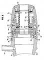
- Fig. 2is an exploded view of the hemostatic valve assembly of Fig. 1 ;
- Fig. 3is an enlarged longitudinal sectional view of a portion of the valve assembly of Fig. 1 ;
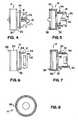
- Fig. 4is a side view of the valve collar
- Fig. 5is a sectional view of the collar of Fig. 4 ;
- Fig. 6is another side view of the collar of Fig. 4 taken from another rotational orientation
- Fig. 7is a sectional view of the collar of Fig. 6 ;
- Fig. 8is an end view of the distal end of collar 14;
- Fig. 9is a distal end view of the rotatable valve control member
- Fig. 10is a side view of the rotatable valve control member
- Fig. 11is a proximal end view of the rotatable valve control member
- Fig. 12is a sectional view of the rotatable valve control member as shown in Fig. 10 ;
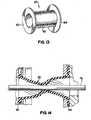
- Fig. 13is a perspective view of the iris valve sheath according to one embodiment of the invention.
- Fig. 14is a sectional view of the iris valve sheath of Fig. 13 , illustrating the valve sheath as it forms a seal around an interventional device.
- proximal and distalwill be used to describe the opposing axial ends of the valve assembly, as well as the axial ends of various components thereof.
- proximalis used in its conventional sense to refer to the end of the assembly (or component thereof) that is closest to the operator during use of the assembly.
- distalis used in its conventional sense to refer to the end of the assembly (or component thereof) that is initially inserted into the patient, or that is closest to the patient during use.
- Fig. 1illustrates a perspective view of a hemostatic valve assembly 10 according to an embodiment of the present invention.
- Fig. 2illustrates an exploded view of hemostatic valve assembly 10 of Fig. 1
- Fig. 3is an enlarged longitudinal sectional view of a portion of the hemostatic valve assembly of Fig. 1 .
- hemostatic valve assembly 10includes a valve chamber 12, a valve collar 14 and a rotatable valve control member 16.
- a check valvecomprising one or more valve disks is disposed longitudinally between valve chamber 12 and valve collar 14.
- the check valvecomprises three longitudinally-aligned valve disks 18 ( Fig. 2 ).
- a flexible valve sheath 20 of the "iris"-typeis disposed between valve collar 14 and rotatable valve control member 16. Iris valves are known in the art and are described, for example, in U.S. Patent Nos. 5,158,553 and 7,172,580 .
- a collar seal 21is provided to secure a flanged end of the iris valve to the valve collar 14.
- Collar seal 21has an aperture 59 therethrough to receive an end of the iris valve.
- An end cap 56is engaged, such as by a snap fit, to the proximal end of rotatable valve control member 16 to secure the other flanged end of the iris valve to rotatable valve control member 16.
- Valve chamber 12comprises an outer housing 29 having a side-arm spout 22 extending transversely therefrom. Spout 22 is sized and shaped for engagement with a tube or other device (not shown) for transmittal or drainage of a fluid or a drug in conventional fashion.
- proximal portion 27 of valve chamber 12is sized for engagement by conventional means with the distal end of valve collar 14.
- the distal end of valve chamber 12comprises a smaller diameter portion 24 for attaching valve assembly 10 to a device, such as introducer sheath 23 ( Fig. 1 ), in conventional fashion.
- Introducer sheath 23is provided for delivering a fluid medicament or a medical device to a target area in the body of the patient in well known fashion.
- a tapered outer member 26is provided to improve the ergonomics of the device, and to provide strain relief in well known fashion.
- Valve disks 18are preferably conventional disk-type valves. Such valve disks are commercially available, for example, from Cook Incorporated, of Bloomington, Indiana, under the trademark CHECK-FLO® valves. Valve disks 18 include one or more slits 19 sized for passage of an interventional device (not shown) therethrough. Preferably, valve disks 18 have a slit on each face thereof. The slits may extend either partially or fully through the disk. Valve disks of this type are well known in the art, and need not be further described herein. Preferably, three valve disks are stacked and arranged such that the slits are aligned as shown in Fig. 2 .
- a complementary-shaped ring member 28( Fig. 2 ) has a channeled or otherwise shaped surface 37 ( Fig. 3 ) for receiving at least the distal most one of disks 18.
- valve collar 14includes a larger diameter generally cylindrical portion 30, and a smaller diameter generally cylindrical portion 32 extending in the proximal direction from large diameter portion 30.
- an external snap ring 34projects radially outwardly from smaller diameter portion 32 for engagement with complementary structure of rotatable valve control member 16.
- an internal snap ring 38projects radially inwardly from large diameter portion 30 for engagement with valve chamber 12.
- a finger 36projects axially in the distal direction from valve collar 14 and is received in cooperating slot 13 in valve chamber 12 for locking valve chamber 12 and valve collar 14 together in a manner such that relative rotation between the valve chamber and the valve collar is precluded.
- valve collar smaller diameter 32includes one or more U-shaped cut-outs 33 along its surface.
- U-shaped cut-outs 33are sized and shaped to define a bridge 41.
- Bridge 41extends generally in the proximal direction from surface 15 of valve collar 14, and terminates in outer ridge 39.
- Outer ridge 39extends radially from bridge 41, and is capable of flexing inwardly into the bore of the collar, in a manner to be described.
- each bridge 41is only supported on one side, with the other three sides defined by the U-shaped cut-out 33.
- Rotatable valve control member 16includes a body 46 having a gentle curved configuration from a smaller diameter proximal end 47 to a larger diameter distal end 48. Providing a curved outer configuration to the rotatable valve control member yields a more ergonomic outer surface than found in prior art designs that may include a substantially cylindrical outer surface. As a result, the physician may more easily grasp and control the device.
- valve control member 16also includes a plurality of optional ribs 50 spaced on the outer surface of body 46 along the gentle curvature. Ribs 50 provide additional ergonomic benefits to facilitate grasping and control by the physician.
- the embodiment shown in the drawingsincludes six ribs equally spaced along the outer surface of body 46. Those skilled in the art will appreciate that the number and spacing of ribs 50 is exemplary only, and that any number and spacing of ribs may be substituted.
- ribs 50may have a multitude of possible cross-sectional shapes, and need not be positioned in generally linear fashion as shown. Rather, any configuration that provides an ergonomic benefit may be substituted.
- the outer body surfacemay be provided with one or more other known ergonomic surfaces, such as nubs, grooves, and the like. Those skilled in the art are readily capable of providing satisfactory alternative ergonomic mechanisms.
- Rotatable valve control member 16also preferably includes a plurality of members, such as ribs 51, disposed along an inner surface of the valve control member. Ribs 51 are configured to engage outer ridges 39 of collar 14 during use of the device, in a manner to be described. In the embodiments shown, eight ribs 51 are provided along the control member inner surface. Those skilled in the art will appreciate that this number is exemplary only, and that more, or fewer, ribs may be substituted. In addition, ribs 51 need not necessarily have the shape as illustrated herein, and other members that are engageable with outer ridges 39 may be substituted.
- each rib 51 of control member 16engage respective outer ridges 39 of collar 14, thereby flexing bridge 41 and outer ridge 39 inwardly into the interior space of the valve.
- the outer ridgeacts in a ratcheting manner, such that a tactile click-type sensation can be felt by the physician upon flexure of the outer ridge resulting from engagement with a respective rib 51.
- each rib 51will successively engage successive outer ridges 39, thereby providing the physician with successive tactile sensations that correspond to the amount of rotation, and closure, of the valve that has taken place.
- each one-eighth rotation of control member 16results in an engagement with an outer ridge 39, thereby producing the tactile click that can be felt by the physician.
- ratcheting mechanismsin valve devices
- such deviceshave typically required that the rotatable member, and/or the collar member, have only a minimal thickness, and a generally cylindrical outer body.
- the membersare capable of flexing relative to one another when the respective ratcheting mechanisms engage, thereby permitting the relative rotation to take place.
- Such surfacesare less ergonomic than desired, and do not provide for optimal manipulation by the physician.
- the ergonomicsare improved, and the physician can more easily grasp and control the valve device.
- Rotatable valve control member 16also includes an inwardly directed snap ring 52 at the distal end thereof. Snap ring 52 is sized and arranged to form a snap fit with external snap ring 34 of valve collar 14. This is best shown in Fig. 3 .
- Rotatable valve control member 16also includes a snap ring 54 at its proximal end. Snap ring 54 is sized and arranged to fixedly engage a complementary snap ring on end cap 56. Rotatable valve control member 16 and end cap 56 are engaged in a manner such that relative rotation between them is precluded.
- Fig. 13illustrates a preferred embodiment of a flexible valve sheath 20.
- Sheath 20comprises a generally cylindrical body 60 having annular flanges 62, 64 disposed at the respective distal and proximal ends of body 60.
- one of the flangesin this case proximal flange 64
- the other flangein this case distal flange 62
- valve sheath 20is illustrated in the figures as having a generally cylindrical main body 60, the main body can have other configurations, such as the accordion-like shape and the hour-glass shape illustrated in Figs. 16 and 17 of U.S. Patent No. 7,172,580 . Still other geometrical-shaped cross-sections may be utilized if desired. Non-limiting examples of such shapes include rectangular, triangular or diamond shapes.
- Valve chamber 12, valve collar 14, rotatable valve control member 16, collar seal 21, and end cap 56are preferably formed of a machined or injection molded relatively hard polymeric material, such as acetal, polypropylene, ABS, nylon, PVC, polyethylene or polycarbonate. Those skilled in the art will appreciate that other suitable compositions may be substituted for those identified herein. As illustrated, each of the aforementioned constituents includes a hollowed-out center portion, such that when the device is fully assembled, a passageway is defined to enable passage of an interventional device therethrough.
- Valve sheath 20is preferably elastomeric, and more preferably, is formed of injection molded silicone.
- a non-limiting list of other suitable materials for use in forming the valve memberincludes isoprene, latex and various rubber or polymeric compositions.
- the durometer of the valve sheathshould be considerably less than the durometer of the body, base and rotatable valve control members, resulting in a valve sheath that is softer and more flexible than the remaining structure.
- all of part of the valve sheathmay be coated with a lubricious coating, such as parylene or a silicone lubricant (e.g., Dow Coming 360 medical fluid), to improve the lubricity of the surface and facilitate the passage of the device therethrough.
- Hemostatic valve assembly 10may be assembled in the following manner. Initially, valve disks 18 are aligned as described above, and loaded into valve collar large diameter portion 30, or into the hood portion of ring member 28. Valve collar large diameter portion 30 is then engaged with valve chamber 12, e.g., via the snap fit previously described, in a manner such that valve disks 18 are compressed into the space between valve chamber 12 and valve collar 14, as shown in Fig. 3 .
- Ring member 28provides a fitted surface for receiving disks 18.
- a thin layer of a sealing lubricantsuch as RTV silicone, is placed between ring 28 and valve chamber 12 to provide a seal at their interface. In this case, the sealing lubricant acts in the nature of a gasket.
- valve collar 14 and valve chamber 12need not be attached by the method described, and other well-known methods of affixation of two parts may be substituted. However, best results are obtained when relative rotation between the two parts is prevented.
- the insertion and capture of valve disks between two substratesis well-known in the medical arts, and those skilled in the art will appreciate that other suitable ways of capturing these valve disks may be substituted for those described.
- Collar seal 21is fitted over the generally cylindrical body 60 of elastomeric valve sheath 20 by any convenient method, such as by temporarily compressing axial annular flange 64 and passing the temporarily compressed end through aperture 59 in the collar seal. ( Fig. 2 ).
- Distal flange 62 of valve sheath 20is axially aligned with valve-receiving surface 15 of valve collar 14.
- Collar seal 21is then urged in the distal direction against distal flange 62 toward valve-receiving surface 15.
- valve collar 14includes slots 25 sized and positioned to mate with corresponding ridges 31 on collar seal 21, to thereby effect a snap fit therebetween.
- collar seal 21compresses flange 62 against valve-receiving surface 15, thereby securing flange 62 in valve collar 14 in a manner that prevents flange 62 from rotating, disengaging or otherwise separating from valve collar 14 during conditions of normal use.
- Valve collar 14 and rotatable valve control member 16are engaged by loosely snapping together valve collar snap ring 34 and rotatable valve control member snap ring 52 to establish a loose snap fit therebetween.
- the engagement of valve collar 14 and rotatable valve control member 16must be loose enough to allow relative rotation therebetween, but secure enough to prevent disengagement during use. This engagement is best shown in Fig. 3 .
- Those skilled in the artwill recognize that other attachment mechanisms may be substituted for the mechanism described, as long as relative rotation is maintained between the valve collar and the rotatable valve control member, and the members are aligned such that they do not disengage during normal use of the device.
- Proximal flange 64 of the elastomeric valve memberis extracted through central aperture 17 ( Figs. 9, 11 ) of rotatable valve control member 16 in the proximal direction by any convenient means, such as by pulling flange 64 through the hole with a suitable tool, such as tweezers.
- a suitable toolsuch as tweezers.
- end cap 56is engaged with rotatable valve control member 16 by, e.g., a snap fit.
- the snap fits described hereinabovecan be accomplished in any convenient fashion, such as by use of a small hand press, or by simply snapping the end cap into place at the proximal end of rotatable valve control member 16.
- valve flange 64is compressed against valve-receiving surface 57 of rotatable valve control member 16, in a similar manner as the previously-described compression of elastomeric valve flange 62 against the valve-receiving surface 15 of valve collar 14.
- the devicecan be provided with a mechanism for limiting the amount of rotation of rotatable member 16 relative to collar 14.
- collar 14includes a tab 35 that is sized and positioned to engage a corresponding stop 55 of rotatable member 16 for limiting the rotation of rotatable member to an amount less than a full revolution of 360°.
- the same mechanism that creates the ratcheting effecthelps keep the valve from recoiling and maintain its current position.
- valve control member 16Operation of the iris valve portion of the hemostatic valve assembly 10 is commenced when the operator grasps rotatable valve control member 16, and rotates this member relative to valve collar 14. Since distal flange 62 and proximal flange 64 of valve sheath 20 are fixedly secured in the respective distal and proximal ends of the valve assembly as described, rotation of valve control member 16 causes an axially intermediate portion (existing between the fixed distal and proximal flanges 62, 64) of the soft polymeric material of the valve member 20 to twist on itself from the opened position shown in the figures to a closed or constricted position. When in this position, the center opening of the valve is twisted, and thereby constricts. Fig.
- valve 14illustrates constriction of the valve member around an interventional device, in this case a dilator 75.
- an interventional devicein this case a dilator 75.
- rotatable member 16may be rotated in a manner to cause the valve to fully close.
- Constriction of a center passageway of an iris valve in the manner describedis known in the art, and is further described and illustrated in the cited documents. Such constriction results in the formation of a seal between the valve and an interventional device inserted therethrough, or alternatively, in closure of the valve when no interventional device is present.
- the iris-type closure utilized in the inventive deviceprovides a particularly effective seal for an introducer sheath or like medical device when catheters or other introducer devices of varying diameters are introduced therein, and also when no catheter is introduced and the lumen of the introducer must be maintained in a closed, leakproof condition.
- the sealalso has a high resistance to tearing when penetrated by large diameter catheters, and is capable of tolerating repeated catheter insertions and withdrawals without any appreciable decrease in performance characteristics of the seal or valve.
- hemostatic valve assembly 10 of the present inventionpreferably includes one or more valve disks 18 in combination with valve sheath 20, the presence of a secondary valve source, such as the valve disks, is not necessarily required.
- the valve chamber 12may be omitted, and its features may be combined in a discrete valve collar 14.
- valve collar 14may be shaped or otherwise configured for attachment to an introducer sheath, and/or may include a side arm spout for transmittal or drainage of a fluid or a drug as described.
- a secondary valve source other than valve disksmay be provided. Such valves are well known, and those skilled in the art can readily select an alternative valve source to the valve disks illustrated and described herein.
Landscapes
- Health & Medical Sciences (AREA)
- Heart & Thoracic Surgery (AREA)
- Pulmonology (AREA)
- Engineering & Computer Science (AREA)
- Anesthesiology (AREA)
- Biomedical Technology (AREA)
- Hematology (AREA)
- Life Sciences & Earth Sciences (AREA)
- Animal Behavior & Ethology (AREA)
- General Health & Medical Sciences (AREA)
- Public Health (AREA)
- Veterinary Medicine (AREA)
- Infusion, Injection, And Reservoir Apparatuses (AREA)
Description
- 1. Technical Field. The present invention relates to a valve assembly for controlling the flow of fluids through a medical device, and more particularly, to a hemostatic valve assembly incorporating an iris valve for controlling fluid flow.
- 2. Background Information. A variety of well-known medical procedures are initiated by introducing an interventional device such as a catheter, trocar, sheath, and the like into a vessel in a patient's body. Typical procedures for introducing an interventional device into a blood vessel include the well-known Seldinger technique. In the Seldinger technique, a needle is injected into a blood vessel, and a wire guide is inserted into the vessel through a bore of the needle. The needle is withdrawn, and a dilator is inserted over the wire guide. The dilator is typically located inside an introducer sheath which is also inserted into the vessel. The introducer sheath typically includes a hemostatic valve, through which the dilator passes. Following proper placement of the introducer sheath, the dilator is removed. The interventional device may then be inserted through the sheath and hemostatic valve into the vessel.
- As the interventional device is introduced into the vessel, care must be taken to avoid the undesirable introduction or leakage of air into the vessel. Similarly, care must be taken to avoid the undesirable leakage of blood or other bodily fluids, or a cavity-pressurizing gas from the patient. As procedures for introducing catheters and other interventional devices have become more widely accepted, the procedures associated with their use have become more diverse, and the variety of sizes and types of such introducer devices has grown dramatically. As a result, the risk of inward or outward leakage of fluids has increased, along with the necessity to maintain vigilance to minimize the possibility of such leakage.
- One known way to minimize leakage is to provide one or more disk-like gaskets in an elongated passageway of a device through which fluids may be controllably passed into or out of the body. Such disks have opposing surfaces and often include one or more slits that extend partially across each of the surfaces and inwardly toward the interior of the disk. A generally axial opening is provided between the slits to provide a sealable path for insertion of an interventional device through the disks. Examples of such disks are described, e.g., in
U.S. Pat. Nos. 5,006,113 and6,416,499 . These disks are generally effective for sealing large diameter devices, but may be less effective for sealing smaller diameter devices. This may be especially true when a smaller diameter device is introduced through a disk following the earlier passage of a larger diameter device.FR-2,863,504 - Another type of valve that is presently used for sealing elongated passages in a medical device to prevent passage of fluids is commonly referred to as an iris valve. Iris valves are described, e.g., in
U.S. Pat. Nos. 5,158,553 and7,172,580 . An iris valve may comprise a valve hub that is joined to a catheter-type device, and a knob that is rotatably engaged with the hub. An elastomeric sleeve having an elongated passageway therethrough is positioned in an opening through the interior of the valve body. The opposing axial ends of the elastomeric sleeve are joined to the hub and the rotatable knob, respectively. When the rotatable knob is rotated in a first direction, the passageway of the elastomeric sleeve is fully opened. When the knob is rotated in a second direction opposite the first direction, the elastomeric sleeve is twisted intermediate the two ends to effect closure of all or part of the elongated passageway. - Although the prior art iris valves are generally effective for sealing sheaths of certain sizes and compositions, such valves have certain shortcomings. For example, the manner of engaging the ends of the valve of the '553 patent to the respective hub and knob is less than optimal. Such ends are capable of disengagement, which destroys the ability of the valve to form a seal. In addition, the outer housing of the valve is not easily grasped by the physician during use.
- The valve of the '580 patent has been found to be generally effective in many applications. This valve may include longitudinal grooves and corresponding ridges that cooperate during rotation of the knob relative to the hub to provide feedback to the physician of the amount of closure of the valve. The particular design of the valve is believed to have sufficient flex in the respective valve parts to enable the knob to be easily rotated relative to the hub. However, the outer contour of this valve is generally cylindrical, and does not provide an ergonomic surface that provides for optimal manipulation by the physician.
- It would be desirable to provide a valve assembly that overcomes the problems associated with prior art iris valves.
- The problems of the prior art are addressed by the features of the present invention. The present invention comprises a valve assembly for controlling a flow of fluid according to claim 1. The valve assembly includes a valve collar, a rotatable valve control member, and a flexible valve member having an opening therethrough. The rotatable valve control member and the valve collar are aligned to define an elongated passageway, and the flexible valve member is disposed along the passageway. The valve collar has a proximal end and a distal end, and is structured such that at least a portion of the proximal end is capable of radial flexure. The rotatable valve control member has a proximal end and a distal end, and includes an ergonomic outer surface. The rotatable valve control member distal end is engaged with the valve collar proximal end in a manner such that the valve control member is at least partially rotatable relative to the valve collar. The rotatable valve control member includes a mechanism for engagement with the valve collar portion upon rotation of the rotatable valve control member. The flexible valve member having a proximal end and a distal end The valve member distal end is secured to the valve collar, and the valve member proximal end is secured to the rotatable valve control member. Upon rotation of the rotatable valve control member in a first direction relative to the valve collar, the mechanism of the rotatable valve control member engages the valve collar portion in a manner such that the valve collar portion flexes in a radial direction and a tactile sensation is produced thereby, and such that the flexible valve member longitudinal opening constricts from an open position to a position wherein the flexible valve member opening is at least partially closed. The valve collar portion is capable of flexure in a radially inward direction and the valve collar comprises at least one generally u-shaped cut-out. The valve collar portion capable of flexure is defined by said generally U-shaped cut-out.
- The valve assembly comprises a valve chamber having a proximal end and a distal end, and a valve collar having a proximal end and a distal end. The valve collar distal end is engaged with the valve chamber proximal end. A proximal portion of the valve collar comprises at least one generally U-shaped cut-out defining a radial ridge portion capable of radial flexure. A rotatable valve control member having a proximal end and a distal end includes an ergonomically arranged outer surface. The outer surface comprises a gently curved outer contour from a smaller diameter proximal end to a larger diameter distal end, and further comprises one or more external members disposed along the contour for facilitating grasping and control of the rotatable valve control member. The rotatable valve control member distal end is engaged with said valve collar proximal end in a manner such that the valve control member is at least partially rotatable relative to the valve collar. The rotatable valve control member includes at least one inner member sized and shaped for engagement with the valve collar ridge in a manner such that the ridge flexes during rotation of the valve control member relative to the valve collar. The valve chamber, valve collar and rotatable valve control member are aligned in the valve assembly to define an elongated passageway therethrough. A flexible valve member has a proximal end and a distal end, wherein the distal end is secured to the valve collar, and the proximal end is secured to the rotatable valve control member. The flexible valve member is disposed along the passageway and has a longitudinal opening therethrough. Upon rotation of the rotatable valve control member in a first direction relative to the valve collar, the inner member of the rotatable valve control member engages a respective valve collar ridge in a manner such that the valve collar portion flexes in a radial direction, and a tactile sensation is produced thereby, and such that the valve member longitudinal opening constricts from an open position to a position wherein the opening is at least partially closed.
Fig. 1 is a perspective view of a hemostatic valve assembly according to an embodiment of the present invention;Fig. 2 is an exploded view of the hemostatic valve assembly ofFig. 1 ;Fig. 3 is an enlarged longitudinal sectional view of a portion of the valve assembly ofFig. 1 ;Fig. 4 is a side view of the valve collar;Fig. 5 is a sectional view of the collar ofFig. 4 ;Fig. 6 is another side view of the collar ofFig. 4 taken from another rotational orientation;Fig. 7 is a sectional view of the collar ofFig. 6 ;Fig. 8 is an end view of the distal end ofcollar 14;Fig. 9 is a distal end view of the rotatable valve control member;Fig. 10 is a side view of the rotatable valve control member;Fig. 11 is a proximal end view of the rotatable valve control member;Fig. 12 is a sectional view of the rotatable valve control member as shown inFig. 10 ;Fig. 13 is a perspective view of the iris valve sheath according to one embodiment of the invention; andFig. 14 is a sectional view of the iris valve sheath ofFig. 13 , illustrating the valve sheath as it forms a seal around an interventional device.- For the purposes of promoting an understanding of the principles of the invention, reference will now be made to the embodiments illustrated in the drawings, and specific language will be used to describe the same. It should nevertheless be understood that no limitation of the scope of the invention is thereby intended, such alterations and further modifications in the illustrated device, and such further applications of the principles of the invention as illustrated therein being contemplated as would normally occur to one skilled in the art to which the invention relates.
- In the following discussion, the terms "proximal" and "distal" will be used to describe the opposing axial ends of the valve assembly, as well as the axial ends of various components thereof. The term "proximal" is used in its conventional sense to refer to the end of the assembly (or component thereof) that is closest to the operator during use of the assembly. The term "distal" is used in its conventional sense to refer to the end of the assembly (or component thereof) that is initially inserted into the patient, or that is closest to the patient during use.
Fig. 1 illustrates a perspective view of ahemostatic valve assembly 10 according to an embodiment of the present invention.Fig. 2 illustrates an exploded view ofhemostatic valve assembly 10 ofFig. 1 , andFig. 3 is an enlarged longitudinal sectional view of a portion of the hemostatic valve assembly ofFig. 1 .- In the preferred embodiment shown,
hemostatic valve assembly 10 includes avalve chamber 12, avalve collar 14 and a rotatablevalve control member 16. A check valve comprising one or more valve disks is disposed longitudinally betweenvalve chamber 12 andvalve collar 14. In the embodiment shown, the check valve comprises three longitudinally-aligned valve disks 18 (Fig. 2 ). Aflexible valve sheath 20 of the "iris"-type is disposed betweenvalve collar 14 and rotatablevalve control member 16. Iris valves are known in the art and are described, for example, inU.S. Patent Nos. 5,158,553 and7,172,580 . Acollar seal 21 is provided to secure a flanged end of the iris valve to thevalve collar 14.Collar seal 21 has anaperture 59 therethrough to receive an end of the iris valve. Anend cap 56 is engaged, such as by a snap fit, to the proximal end of rotatablevalve control member 16 to secure the other flanged end of the iris valve to rotatablevalve control member 16. Valve chamber 12 comprises anouter housing 29 having a side-arm spout 22 extending transversely therefrom.Spout 22 is sized and shaped for engagement with a tube or other device (not shown) for transmittal or drainage of a fluid or a drug in conventional fashion. In the preferred embodiment shown,proximal portion 27 ofvalve chamber 12 is sized for engagement by conventional means with the distal end ofvalve collar 14. The distal end ofvalve chamber 12 comprises asmaller diameter portion 24 for attachingvalve assembly 10 to a device, such as introducer sheath 23 (Fig. 1 ), in conventional fashion. Introducer sheath 23 is provided for delivering a fluid medicament or a medical device to a target area in the body of the patient in well known fashion. Preferably a taperedouter member 26 is provided to improve the ergonomics of the device, and to provide strain relief in well known fashion.Valve disks 18 are preferably conventional disk-type valves. Such valve disks are commercially available, for example, from Cook Incorporated, of Bloomington, Indiana, under the trademark CHECK-FLO® valves.Valve disks 18 include one ormore slits 19 sized for passage of an interventional device (not shown) therethrough. Preferably,valve disks 18 have a slit on each face thereof. The slits may extend either partially or fully through the disk. Valve disks of this type are well known in the art, and need not be further described herein. Preferably, three valve disks are stacked and arranged such that the slits are aligned as shown inFig. 2 . However, those skilled in the art will appreciate that other numbers of disks may be utilized, and the alignment of the slits in the disks need not be as shown in the figures. Preferably, a complementary-shaped ring member 28 (Fig. 2 ) has a channeled or otherwise shaped surface 37 (Fig. 3 ) for receiving at least the distal most one ofdisks 18.- A preferred embodiment of
valve collar 14 is shown in greater detail inFigs. 4-8 .Valve collar 14 includes a larger diameter generallycylindrical portion 30, and a smaller diameter generallycylindrical portion 32 extending in the proximal direction fromlarge diameter portion 30. Preferably anexternal snap ring 34 projects radially outwardly fromsmaller diameter portion 32 for engagement with complementary structure of rotatablevalve control member 16. In the preferred embodiment shown, an internal snap ring 38 (Figs. 3 ,5 ) projects radially inwardly fromlarge diameter portion 30 for engagement withvalve chamber 12. Afinger 36 projects axially in the distal direction fromvalve collar 14 and is received in cooperatingslot 13 invalve chamber 12 for lockingvalve chamber 12 andvalve collar 14 together in a manner such that relative rotation between the valve chamber and the valve collar is precluded. - In the preferred embodiment shown, valve collar
smaller diameter 32 includes one or more U-shaped cut-outs 33 along its surface. U-shaped cut-outs 33 are sized and shaped to define abridge 41.Bridge 41 extends generally in the proximal direction fromsurface 15 ofvalve collar 14, and terminates inouter ridge 39.Outer ridge 39 extends radially frombridge 41, and is capable of flexing inwardly into the bore of the collar, in a manner to be described. In this embodiment, eachbridge 41 is only supported on one side, with the other three sides defined by the U-shaped cut-out 33. - A preferred embodiment of rotatable
valve control member 16 is illustrated in greater detail inFigs. 9-12 . Rotatablevalve control member 16 includes abody 46 having a gentle curved configuration from a smaller diameterproximal end 47 to a larger diameterdistal end 48. Providing a curved outer configuration to the rotatable valve control member yields a more ergonomic outer surface than found in prior art designs that may include a substantially cylindrical outer surface. As a result, the physician may more easily grasp and control the device. - In the preferred embodiment shown,
valve control member 16 also includes a plurality ofoptional ribs 50 spaced on the outer surface ofbody 46 along the gentle curvature.Ribs 50 provide additional ergonomic benefits to facilitate grasping and control by the physician. The embodiment shown in the drawings includes six ribs equally spaced along the outer surface ofbody 46. Those skilled in the art will appreciate that the number and spacing ofribs 50 is exemplary only, and that any number and spacing of ribs may be substituted. In addition,ribs 50 may have a multitude of possible cross-sectional shapes, and need not be positioned in generally linear fashion as shown. Rather, any configuration that provides an ergonomic benefit may be substituted. As an alternative to ribs, the outer body surface may be provided with one or more other known ergonomic surfaces, such as nubs, grooves, and the like. Those skilled in the art are readily capable of providing satisfactory alternative ergonomic mechanisms. - Rotatable
valve control member 16 also preferably includes a plurality of members, such asribs 51, disposed along an inner surface of the valve control member.Ribs 51 are configured to engageouter ridges 39 ofcollar 14 during use of the device, in a manner to be described. In the embodiments shown, eightribs 51 are provided along the control member inner surface. Those skilled in the art will appreciate that this number is exemplary only, and that more, or fewer, ribs may be substituted. In addition,ribs 51 need not necessarily have the shape as illustrated herein, and other members that are engageable withouter ridges 39 may be substituted. - For rotation of rotatable
valve control member 16 relative tocollar 14, the operator rotates and applies a torque to rotatablevalve control member 16. During rotation,inner ribs 51 ofcontrol member 16 engage respectiveouter ridges 39 ofcollar 14, thereby flexingbridge 41 andouter ridge 39 inwardly into the interior space of the valve. Upon such engagement and flexure, the outer ridge acts in a ratcheting manner, such that a tactile click-type sensation can be felt by the physician upon flexure of the outer ridge resulting from engagement with arespective rib 51. Ascontrol member 16 is further rotated, eachrib 51 will successively engage successiveouter ridges 39, thereby providing the physician with successive tactile sensations that correspond to the amount of rotation, and closure, of the valve that has taken place. In the preferred design having eightribs 51, each one-eighth rotation ofcontrol member 16 results in an engagement with anouter ridge 39, thereby producing the tactile click that can be felt by the physician. - Although some prior art devices have included ratcheting mechanisms in valve devices, such devices have typically required that the rotatable member, and/or the collar member, have only a minimal thickness, and a generally cylindrical outer body. As a result, the members are capable of flexing relative to one another when the respective ratcheting mechanisms engage, thereby permitting the relative rotation to take place. Such surfaces are less ergonomic than desired, and do not provide for optimal manipulation by the physician. By providing a thicker and more contoured rotatable valve control member as described, the ergonomics are improved, and the physician can more easily grasp and control the valve device. However, when a thicker valve control member is utilized, relative rotation between the members is inhibited, or prevented entirely, because the increased thickness hinders the ability of the rotatable member to flex. The arrangement described herein enables such relative rotation to occur as a result of the flexure of the outer ridge, and also allows ratcheting action that provides the tactile feedback to the physician.
- Rotatable
valve control member 16 also includes an inwardly directedsnap ring 52 at the distal end thereof.Snap ring 52 is sized and arranged to form a snap fit withexternal snap ring 34 ofvalve collar 14. This is best shown inFig. 3 . Rotatablevalve control member 16 also includes asnap ring 54 at its proximal end.Snap ring 54 is sized and arranged to fixedly engage a complementary snap ring onend cap 56. Rotatablevalve control member 16 andend cap 56 are engaged in a manner such that relative rotation between them is precluded. Fig. 13 illustrates a preferred embodiment of aflexible valve sheath 20.Sheath 20 comprises a generallycylindrical body 60 havingannular flanges body 60. In the preferred embodiment shown, one of the flanges (in this case proximal flange 64) has a larger diameter, and the other flange (in this case distal flange 62) has a smaller diameter.- Although
valve sheath 20 is illustrated in the figures as having a generally cylindricalmain body 60, the main body can have other configurations, such as the accordion-like shape and the hour-glass shape illustrated in Figs. 16 and 17 ofU.S. Patent No. 7,172,580 . Still other geometrical-shaped cross-sections may be utilized if desired. Non-limiting examples of such shapes include rectangular, triangular or diamond shapes. Valve chamber 12,valve collar 14, rotatablevalve control member 16,collar seal 21, andend cap 56 are preferably formed of a machined or injection molded relatively hard polymeric material, such as acetal, polypropylene, ABS, nylon, PVC, polyethylene or polycarbonate. Those skilled in the art will appreciate that other suitable compositions may be substituted for those identified herein. As illustrated, each of the aforementioned constituents includes a hollowed-out center portion, such that when the device is fully assembled, a passageway is defined to enable passage of an interventional device therethrough.Valve sheath 20 is preferably elastomeric, and more preferably, is formed of injection molded silicone. A non-limiting list of other suitable materials for use in forming the valve member includes isoprene, latex and various rubber or polymeric compositions. For the purposes of the present invention, the durometer of the valve sheath should be considerably less than the durometer of the body, base and rotatable valve control members, resulting in a valve sheath that is softer and more flexible than the remaining structure. If desired, all of part of the valve sheath may be coated with a lubricious coating, such as parylene or a silicone lubricant (e.g., Dow Coming 360 medical fluid), to improve the lubricity of the surface and facilitate the passage of the device therethrough.Hemostatic valve assembly 10 may be assembled in the following manner. Initially,valve disks 18 are aligned as described above, and loaded into valve collarlarge diameter portion 30, or into the hood portion ofring member 28. Valve collarlarge diameter portion 30 is then engaged withvalve chamber 12, e.g., via the snap fit previously described, in a manner such thatvalve disks 18 are compressed into the space betweenvalve chamber 12 andvalve collar 14, as shown inFig. 3 .Ring member 28 provides a fitted surface for receivingdisks 18. Preferably, a thin layer of a sealing lubricant, such as RTV silicone, is placed betweenring 28 andvalve chamber 12 to provide a seal at their interface. In this case, the sealing lubricant acts in the nature of a gasket.- Those skilled in the art will appreciate that
valve collar 14 andvalve chamber 12 need not be attached by the method described, and other well-known methods of affixation of two parts may be substituted. However, best results are obtained when relative rotation between the two parts is prevented. The insertion and capture of valve disks between two substrates is well-known in the medical arts, and those skilled in the art will appreciate that other suitable ways of capturing these valve disks may be substituted for those described. Collar seal 21 is fitted over the generallycylindrical body 60 ofelastomeric valve sheath 20 by any convenient method, such as by temporarily compressing axialannular flange 64 and passing the temporarily compressed end throughaperture 59 in the collar seal. (Fig. 2 ).Distal flange 62 ofvalve sheath 20 is axially aligned with valve-receivingsurface 15 ofvalve collar 14.Collar seal 21 is then urged in the distal direction againstdistal flange 62 toward valve-receivingsurface 15. Preferably,valve collar 14 includesslots 25 sized and positioned to mate with correspondingridges 31 oncollar seal 21, to thereby effect a snap fit therebetween. When snapped together,collar seal 21 compresses flange 62 against valve-receivingsurface 15, thereby securingflange 62 invalve collar 14 in a manner that preventsflange 62 from rotating, disengaging or otherwise separating fromvalve collar 14 during conditions of normal use.Valve collar 14 and rotatablevalve control member 16 are engaged by loosely snapping together valvecollar snap ring 34 and rotatable valve controlmember snap ring 52 to establish a loose snap fit therebetween. The engagement ofvalve collar 14 and rotatablevalve control member 16 must be loose enough to allow relative rotation therebetween, but secure enough to prevent disengagement during use. This engagement is best shown inFig. 3 . Those skilled in the art will recognize that other attachment mechanisms may be substituted for the mechanism described, as long as relative rotation is maintained between the valve collar and the rotatable valve control member, and the members are aligned such that they do not disengage during normal use of the device.Proximal flange 64 of the elastomeric valve member is extracted through central aperture 17 (Figs. 9, 11 ) of rotatablevalve control member 16 in the proximal direction by any convenient means, such as by pullingflange 64 through the hole with a suitable tool, such as tweezers. Withproximal flange 64 resting on rotatable valve control member valve-receivingsurface 57,end cap 56 is engaged with rotatablevalve control member 16 by, e.g., a snap fit. The snap fits described hereinabove can be accomplished in any convenient fashion, such as by use of a small hand press, or by simply snapping the end cap into place at the proximal end of rotatablevalve control member 16. Alternatively, instead of a snap fit, those skilled in the art will appreciate that other engagement means known in the art can be substituted, such as mating screw threads or a friction fit. When the device is assembled,elastomeric valve flange 64 is compressed against valve-receivingsurface 57 of rotatablevalve control member 16, in a similar manner as the previously-described compression ofelastomeric valve flange 62 against the valve-receivingsurface 15 ofvalve collar 14.- If desired, the device can be provided with a mechanism for limiting the amount of rotation of
rotatable member 16 relative tocollar 14. In the embodiment shown,collar 14 includes atab 35 that is sized and positioned to engage acorresponding stop 55 ofrotatable member 16 for limiting the rotation of rotatable member to an amount less than a full revolution of 360°. The same mechanism that creates the ratcheting effect helps keep the valve from recoiling and maintain its current position. - Operation of the iris valve portion of the
hemostatic valve assembly 10 is commenced when the operator grasps rotatablevalve control member 16, and rotates this member relative tovalve collar 14. Sincedistal flange 62 andproximal flange 64 ofvalve sheath 20 are fixedly secured in the respective distal and proximal ends of the valve assembly as described, rotation ofvalve control member 16 causes an axially intermediate portion (existing between the fixed distal andproximal flanges 62, 64) of the soft polymeric material of thevalve member 20 to twist on itself from the opened position shown in the figures to a closed or constricted position. When in this position, the center opening of the valve is twisted, and thereby constricts.Fig. 14 illustrates constriction of the valve member around an interventional device, in this case adilator 75. When an interventional device is not present,rotatable member 16 may be rotated in a manner to cause the valve to fully close. Constriction of a center passageway of an iris valve in the manner described is known in the art, and is further described and illustrated in the cited documents. Such constriction results in the formation of a seal between the valve and an interventional device inserted therethrough, or alternatively, in closure of the valve when no interventional device is present. - The iris-type closure utilized in the inventive device provides a particularly effective seal for an introducer sheath or like medical device when catheters or other introducer devices of varying diameters are introduced therein, and also when no catheter is introduced and the lumen of the introducer must be maintained in a closed, leakproof condition. The seal also has a high resistance to tearing when penetrated by large diameter catheters, and is capable of tolerating repeated catheter insertions and withdrawals without any appreciable decrease in performance characteristics of the seal or valve.
- Although the preferred embodiment of
hemostatic valve assembly 10 of the present invention preferably includes one ormore valve disks 18 in combination withvalve sheath 20, the presence of a secondary valve source, such as the valve disks, is not necessarily required. In this event, thevalve chamber 12 may be omitted, and its features may be combined in adiscrete valve collar 14. If desired,valve collar 14 may be shaped or otherwise configured for attachment to an introducer sheath, and/or may include a side arm spout for transmittal or drainage of a fluid or a drug as described. As a still further alternative, a secondary valve source other than valve disks may be provided. Such valves are well known, and those skilled in the art can readily select an alternative valve source to the valve disks illustrated and described herein. - While this invention has been particularly shown and described with reference to preferred embodiments thereof, it will be understood by those skilled in the art that various changes in form and details may be made. Those skilled in the art may recognize or be able to ascertain using no more than routine experimentation, many equivalents to the specific embodiments of the invention described specifically herein.
Claims (12)
- A valve assembly for controlling a flow of fluid, said valve assembly comprising:a valve collar (14) having a proximal end and a distal end, said valve collar structured such that at least a portion of said proximal end is capable of radial flexure;a rotatable valve control member (16) having a proximal end and a distal end, said rotatable valve control member (16) including an ergonomically arranged outer surface, said rotatable valve control member distal end being engaged with said valve collar proximal end in a manner such that said valve control member (16) is at least partially rotatable relative to said valve collar (14), said rotatable valve control member (16) including a mechanism for engagement with said valve collar portion upon rotation of said rotatable valve control member, said rotatable valve control member (16) and said valve collar (14) being aligned to define an elongated passageway; anda flexible valve member (20) having a proximal end and a distal end, said valve member distal end being secured to said valve collar (14), and said valve member proximal end being secured to said rotatable valve control member (16) ; said flexible valve member (20) being disposed along said passageway and having a longitudinal opening therethrough;wherein upon rotation of said rotatable valve control member (16) in a first direction relative to said valve collar (14), said mechanism of said rotatable valve control member engages said valve collar portion in a manner such that said valve collar portion flexes in a radial direction and a tactile sensation is produced thereby, and such that said flexible valve member longitudinal opening constricts from an open position to a position wherein said opening is at least partially closed;wherein said valve collar portion is capable of flexure in a radially inward direction; andcharacterized in that said valve collar comprises at least one generally U-shaped cut-out (33), and said valve collar portion capable of flexure is defined by said generally U-shaped cut-out (33).
- The valve assembly of claim 1, wherein said valve collar (14) comprises a plurality of generally U-shaped cut-outs (33), wherein a valve collar portion capable of flexure is defined by each of said generally U-shaped cut-outs.
- The valve assembly of claim 1, wherein said valve collar portion comprises at least one bridge (41) defined by said U-shaped cut-out, and an outer ridge (39) projecting in a radially outer direction from a terminal end of said bridge (41).
- The valve assembly of claim 1, wherein said ergonomically arranged outer surface of said rotatable valve control member (16) comprises a plurality of members projecting radially outwardly from said outer surface.
- The valve assembly of claim 1, wherein said rotatable valve control member (16) is provided with a gently curved outer contour from a smaller diameter proximal end to a larger diameter distal end.
- The valve control assembly of claim 7, wherein said rotatable valve control member (16) has a thickness such that flexure of said rotatable valve control member relative to said valve collar (14) during rotation is substantially inhibited.
- The valve assembly of claim 6, wherein said ergonomically arranged outer surface comprises a plurality of ribs (50) disposed along said outer surface.
- The valve assembly of claim 4, wherein said ergonomically arranged outer surface comprises a plurality of ribs (50) disposed along said outer surface.
- The valve assembly of claim 6, wherein said mechanism of said rotatable valve control member comprises at least one inner member sized and shaped for engagement with said valve collar portion in a manner such that said valve collar portion is capable of flexure during rotation of said valve control member (16) relative to said valve collar (14), thereby facilitating said rotation.
- The valve assembly of claim 3, wherein said mechanism of said rotatable valve control member (16) comprises at least one inner member sized and shaped for engagement with said outer ridge.
- The valve assembly of claim 1, comprising a valve chamber (12) having a proximal end and a distal end, said valve chamber (12) proximal end engaged with said valve collar distal end in a manner such that a passageway is disposed therebetween, said valve assembly further comprising a valve member (18) disposed in said passageway between said valve chamber and said valve collar.
- The valve assembly of claim 11, wherein said valve member comprises at least one valve disk (18).
Applications Claiming Priority (2)
| Application Number | Priority Date | Filing Date | Title |
|---|---|---|---|
| US87823207P | 2007-01-03 | 2007-01-03 | |
| PCT/US2007/089059WO2008085772A1 (en) | 2007-01-03 | 2007-12-28 | Valve assembly |
Publications (2)
| Publication Number | Publication Date |
|---|---|
| EP2101859A1 EP2101859A1 (en) | 2009-09-23 |
| EP2101859B1true EP2101859B1 (en) | 2013-11-06 |
Family
ID=39332160
Family Applications (1)
| Application Number | Title | Priority Date | Filing Date |
|---|---|---|---|
| EP07866097.4AActiveEP2101859B1 (en) | 2007-01-03 | 2007-12-28 | Valve assembly |
Country Status (6)
| Country | Link |
|---|---|
| US (1) | US8002749B2 (en) |
| EP (1) | EP2101859B1 (en) |
| JP (1) | JP5255571B2 (en) |
| AU (1) | AU2007342106B2 (en) |
| CA (1) | CA2673844C (en) |
| WO (1) | WO2008085772A1 (en) |
Families Citing this family (62)
| Publication number | Priority date | Publication date | Assignee | Title |
|---|---|---|---|---|
| US11259945B2 (en) | 2003-09-03 | 2022-03-01 | Bolton Medical, Inc. | Dual capture device for stent graft delivery system and method for capturing a stent graft |
| US8292943B2 (en) | 2003-09-03 | 2012-10-23 | Bolton Medical, Inc. | Stent graft with longitudinal support member |
| US7686825B2 (en) | 2004-03-25 | 2010-03-30 | Hauser David L | Vascular filter device |
| US20080171988A1 (en)* | 2007-01-17 | 2008-07-17 | Erblan Surgical, Inc. | Double-cone sphincter introducer assembly and integrated valve assembly |
| CN102076281B (en) | 2008-06-30 | 2014-11-05 | 波顿医疗公司 | Systems and methods for abdominal aortic aneurysm |
| US7963948B2 (en)* | 2009-02-06 | 2011-06-21 | Cook Medical Technologies Llc | Hemostasis valve system |
| WO2010104694A1 (en) | 2009-03-12 | 2010-09-16 | Cook Incorporated | Hemostasis valve assembly |
| EP3284447B1 (en) | 2009-03-13 | 2020-05-20 | Bolton Medical Inc. | System for deploying an endoluminal prosthesis at a surgical site |
| US20100249518A1 (en)* | 2009-03-24 | 2010-09-30 | Battles Christopher A | Three piece elastic disk |
| US9205244B2 (en) | 2009-06-29 | 2015-12-08 | Cook Medical Technologies Llc | Haemostatic valve device |
| US8267897B2 (en)* | 2010-01-06 | 2012-09-18 | W. L. Gore & Associates, Inc. | Center twist hemostatic valve |
| US8414486B2 (en) | 2010-03-25 | 2013-04-09 | Covidien Lp | Portal apparatus with a finger seal assembly |
| US8777893B2 (en)* | 2010-04-09 | 2014-07-15 | Medtronic, Inc. | Variable hemostasis valve and method of use |
| US8137321B2 (en)* | 2010-05-12 | 2012-03-20 | Medtronic Vascular, Inc. | Introducer sheath |
| US9440059B2 (en) | 2011-03-18 | 2016-09-13 | Cook Medical Technologies Llc | Adjustable diameter hemostatic valve |
| US10485524B2 (en) | 2011-10-25 | 2019-11-26 | Essential Medical, Inc. | Instrument and methods for surgically closing percutaneous punctures |
| US9737686B2 (en) | 2012-03-12 | 2017-08-22 | Becton, Dickinson And Company | Catheter adapter port valve |
| EP2846713A1 (en) | 2012-05-09 | 2015-03-18 | EON Surgical Ltd. | Laparoscopic port |
| US9757104B2 (en) | 2012-07-19 | 2017-09-12 | Essential Medical, Inc. | Multi-lumen tamper tube |
| US9913972B2 (en)* | 2012-09-07 | 2018-03-13 | Intuitive Surgical Operations, Inc. | Cannula seal |
| WO2014047650A1 (en) | 2012-09-24 | 2014-03-27 | Inceptus Medical LLC | Device and method for treating vascular occlusion |
| US8784434B2 (en) | 2012-11-20 | 2014-07-22 | Inceptus Medical, Inc. | Methods and apparatus for treating embolism |
| US9510818B2 (en)* | 2012-12-05 | 2016-12-06 | St. Jude Medical Luxembourg Holdings SMI S.A.R.L. (“SJM LUX SMI”) | Twist-grip anchors and methods of use |
| US9439751B2 (en) | 2013-03-15 | 2016-09-13 | Bolton Medical, Inc. | Hemostasis valve and delivery systems |
| EP3146993B1 (en)* | 2013-03-15 | 2018-06-06 | Bolton Medical, Inc. | Hemostasis valve and delivery systems |
| US10639019B2 (en) | 2013-03-15 | 2020-05-05 | Arrow International, Inc. | Vascular closure devices and methods of use |
| US9439796B2 (en) | 2013-03-15 | 2016-09-13 | Cook Medical Technologies Llc | Prosthesis delivery device |
| BR302013005133S1 (en)* | 2013-04-08 | 2015-01-20 | Cardio3 Biosciences Sa | SETTING APPLIED TO CATHETER HANDLE |
| USD776805S1 (en) | 2013-04-08 | 2017-01-17 | Celyad S.A. | Injection catheter handle |
| BR302013005132S1 (en) | 2013-04-08 | 2015-01-20 | Cardio3 Biosciences Sa | CONFIGURATION APPLIED TO CATHETER HANDLE ELEMENT |
| US10238406B2 (en) | 2013-10-21 | 2019-03-26 | Inari Medical, Inc. | Methods and apparatus for treating embolism |
| EP3858254B1 (en) | 2013-12-23 | 2024-04-24 | Teleflex Life Sciences LLC | Vascular closure device |
| CN106470728A (en) | 2014-06-09 | 2017-03-01 | 因赛普特斯医学有限责任公司 | Retraction and suction device and related systems and methods for treating embolism |
| US10555727B2 (en) | 2015-06-26 | 2020-02-11 | Essential Medical, Inc. | Vascular closure device with removable guide member |
| USD791978S1 (en)* | 2015-08-27 | 2017-07-11 | Vimecon Gmbh | Catheter handle |
| US10342571B2 (en) | 2015-10-23 | 2019-07-09 | Inari Medical, Inc. | Intravascular treatment of vascular occlusion and associated devices, systems, and methods |
| CN113796927B (en) | 2015-10-23 | 2025-03-04 | 伊纳里医疗公司 | Intravascular treatment of vascular occlusion and related devices, systems and methods |
| US9700332B2 (en) | 2015-10-23 | 2017-07-11 | Inari Medical, Inc. | Intravascular treatment of vascular occlusion and associated devices, systems, and methods |
| CN115300748A (en) | 2015-12-18 | 2022-11-08 | 伊纳里医疗有限公司 | Catheter shaft and related devices, systems and methods |
| FI3528717T3 (en) | 2016-10-24 | 2024-08-09 | Inari Medical Inc | Devices for treating vascular occlusion |
| WO2018169685A1 (en)* | 2017-03-13 | 2018-09-20 | Boston Scientific Scimed, Inc. | Hemostasis valves and methods for making and using hemostasis valves |
| CN110636879B (en) | 2017-03-13 | 2022-01-04 | 波士顿科学有限公司 | Hemostatic valve and methods for making and using a hemostatic valve |
| WO2018169683A1 (en)* | 2017-03-13 | 2018-09-20 | Boston Scientific Scimed, Inc. | Hemostasis valves and methods for making and using hemostasis valves |
| US11291821B2 (en) | 2017-03-13 | 2022-04-05 | Boston Scientific Limited | Hemostasis valves and methods for making and using hemostasis valves |
| WO2019050765A1 (en) | 2017-09-06 | 2019-03-14 | Inari Medical, Inc. | Hemostasis valves and methods of use |
| WO2019055411A1 (en) | 2017-09-12 | 2019-03-21 | Boston Scientific Limited | Hemostasis valves and methods for making and using hemostasis valves |
| JP6483784B2 (en)* | 2017-10-31 | 2019-03-13 | ボルトン メディカル インコーポレイテッド | Hemostatic valve and delivery system |
| US11154314B2 (en) | 2018-01-26 | 2021-10-26 | Inari Medical, Inc. | Single insertion delivery system for treating embolism and associated systems and methods |
| GB2574607B (en)* | 2018-06-11 | 2022-06-15 | Mprd Ltd | Testing instrument comprising a mouthpiece holder |
| CA3114285A1 (en) | 2018-08-13 | 2020-02-20 | Inari Medical, Inc. | System for treating embolism and associated devices and methods |
| JP6811792B2 (en)* | 2019-02-14 | 2021-01-13 | ボルトン メディカル インコーポレイテッド | Hemostasis valve and delivery system |
| JP7638273B2 (en) | 2019-10-16 | 2025-03-03 | イナリ メディカル, インコーポレイテッド | Systems, devices and methods for treating vascular obstructions |
| CN114787496B (en)* | 2019-12-03 | 2023-04-14 | 全耐塑料高级创新研究公司 | Vehicle mounted aqueous solution injection system with mechanical valve |
| US11752317B2 (en)* | 2020-02-04 | 2023-09-12 | Medtronic, Inc. | Hemostasis valve orientation relative to the fluid space in a introducer sheath |
| CN111568200B (en)* | 2020-06-03 | 2024-09-13 | 苏州咖博士咖啡系统科技有限公司 | Milk container of coffee machine |
| US12390249B2 (en)* | 2020-07-31 | 2025-08-19 | Teleflex Life Sciences Llc | Access sheath with valve assembly |
| US20220183664A1 (en)* | 2020-12-10 | 2022-06-16 | Olympus Medical Systems Corporation | Real-time sampling system |
| CN113577513A (en)* | 2021-08-10 | 2021-11-02 | 上海腾复医疗科技有限公司 | Conduit sealing device |
| EP4463083A1 (en) | 2022-01-11 | 2024-11-20 | Inari Medical, Inc. | Devices for removing clot material from intravascularly implanted devices, and associated systems and methods |
| CN115350394A (en)* | 2022-08-18 | 2022-11-18 | 复旦大学附属肿瘤医院 | Hemostatic valve for use with coaxial trocars and biopsy needles |
| CN116570830B (en)* | 2023-05-30 | 2024-03-22 | 北京管桥医疗科技有限公司 | Vascular sheath hemostasis valve and medical instrument |
| CN119668382B (en)* | 2025-02-24 | 2025-06-03 | 上海电子信息职业技术学院 | Adjustable computer heat dissipation device and heat dissipation method |
Family Cites Families (11)
| Publication number | Priority date | Publication date | Assignee | Title |
|---|---|---|---|---|
| US4292969A (en)* | 1979-12-19 | 1981-10-06 | Raible Donald A | Fluid regulating device with torsional control |
| US4540411A (en)* | 1983-11-28 | 1985-09-10 | Sherwood Medical Company | Catheter placement device |
| US5006113A (en) | 1990-02-08 | 1991-04-09 | Cook Incorporated | Hemostasis cannula |
| US5158553A (en) | 1990-12-26 | 1992-10-27 | Cardiopulmonics | Rotatably actuated constricting catheter valve |
| US5361283A (en)* | 1994-03-15 | 1994-11-01 | B&W Fuel Company | Guide tube retainer |
| AU745352B2 (en) | 1997-07-30 | 2002-03-21 | Cook Medical Technologies Llc | Medical fluid flow control valve |
| DE60211942T2 (en)* | 2001-12-04 | 2007-01-25 | Cook Inc., Bloomington | ACCESS VALVE |
| WO2004110548A1 (en)* | 2003-06-17 | 2004-12-23 | Cube Medical A/S | Closure with passage slit for a haemostatic valve assembly |
| FR2863504B1 (en) | 2003-12-10 | 2006-09-29 | Claude Mialhe | VALVE FOR SURGICAL OR MEDICAL INSTRUMENT |
| EP1691884B1 (en)* | 2003-12-11 | 2011-03-23 | Cook Incorporated | Hemostatic valve assembly |
| US20070204924A1 (en)* | 2004-10-28 | 2007-09-06 | Pall Corporation | Valve |
- 2007
- 2007-12-28USUS11/966,385patent/US8002749B2/enactiveActive
- 2007-12-28CACA2673844Apatent/CA2673844C/enactiveActive
- 2007-12-28JPJP2009544901Apatent/JP5255571B2/enactiveActive
- 2007-12-28EPEP07866097.4Apatent/EP2101859B1/enactiveActive
- 2007-12-28AUAU2007342106Apatent/AU2007342106B2/enactiveActive
- 2007-12-28WOPCT/US2007/089059patent/WO2008085772A1/enactiveApplication Filing
Also Published As
| Publication number | Publication date |
|---|---|
| WO2008085772A1 (en) | 2008-07-17 |
| US20080157017A1 (en) | 2008-07-03 |
| AU2007342106A1 (en) | 2008-07-17 |
| EP2101859A1 (en) | 2009-09-23 |
| US8002749B2 (en) | 2011-08-23 |
| CA2673844C (en) | 2012-06-05 |
| AU2007342106B2 (en) | 2013-01-24 |
| JP5255571B2 (en) | 2013-08-07 |
| CA2673844A1 (en) | 2008-07-17 |
| JP2010514535A (en) | 2010-05-06 |
Similar Documents
| Publication | Publication Date | Title |
|---|---|---|
| EP2101859B1 (en) | Valve assembly | |
| JP2010514535A5 (en) | ||
| EP1691884B1 (en) | Hemostatic valve assembly | |
| AU621359B2 (en) | Self-sealing guidewire and catheter introducer | |
| EP1359968B1 (en) | Hemostasis valve | |
| US5304156A (en) | Self-sealing guidewire and catheter introducer | |
| US6416499B2 (en) | Medical fluid flow control valve | |
| US5935112A (en) | Hemostasis valve with catheter/guidewire seals | |
| US20060217665A1 (en) | Surgical instrument seal assembly and triple lead thread | |
| US20060211992A1 (en) | Surgical instrument seal assembly and triple lead thread | |
| US9108032B2 (en) | Hemostasis valve assembly | |
| US12408945B2 (en) | Insertion devices | |
| US20120310178A1 (en) | Valve assembly | |
| WO2025205999A1 (en) | Medical device and deflection operation device for medical equipment |
Legal Events
| Date | Code | Title | Description |
|---|---|---|---|
| PUAI | Public reference made under article 153(3) epc to a published international application that has entered the european phase | Free format text:ORIGINAL CODE: 0009012 | |
| 17P | Request for examination filed | Effective date:20090622 | |
| AK | Designated contracting states | Kind code of ref document:A1 Designated state(s):AT BE BG CH CY CZ DE DK EE ES FI FR GB GR HU IE IS IT LI LT LU LV MC MT NL PL PT RO SE SI SK TR | |
| RIN1 | Information on inventor provided before grant (corrected) | Inventor name:MACATANGAY, EDWIN, E. Inventor name:HOWAT, WILLIAM, L. | |
| DAX | Request for extension of the european patent (deleted) | ||
| RAP1 | Party data changed (applicant data changed or rights of an application transferred) | Owner name:COOK MEDICAL TECHNOLOGIES LLC | |
| RAP1 | Party data changed (applicant data changed or rights of an application transferred) | Owner name:COOK MEDICAL TECHNOLOGIES LLC | |
| 17Q | First examination report despatched | Effective date:20130226 | |
| GRAP | Despatch of communication of intention to grant a patent | Free format text:ORIGINAL CODE: EPIDOSNIGR1 | |
| INTG | Intention to grant announced | Effective date:20130705 | |
| GRAS | Grant fee paid | Free format text:ORIGINAL CODE: EPIDOSNIGR3 | |
| GRAA | (expected) grant | Free format text:ORIGINAL CODE: 0009210 | |
| AK | Designated contracting states | Kind code of ref document:B1 Designated state(s):AT BE BG CH CY CZ DE DK EE ES FI FR GB GR HU IE IS IT LI LT LU LV MC MT NL PL PT RO SE SI SK TR | |
| REG | Reference to a national code | Ref country code:GB Ref legal event code:FG4D | |
| REG | Reference to a national code | Ref country code:CH Ref legal event code:EP | |
| REG | Reference to a national code | Ref country code:AT Ref legal event code:REF Ref document number:639009 Country of ref document:AT Kind code of ref document:T Effective date:20131215 | |
| REG | Reference to a national code | Ref country code:IE Ref legal event code:FG4D | |
| REG | Reference to a national code | Ref country code:DE Ref legal event code:R096 Ref document number:602007033744 Country of ref document:DE Effective date:20140102 | |
| REG | Reference to a national code | Ref country code:NL Ref legal event code:VDEP Effective date:20131106 | |
| REG | Reference to a national code | Ref country code:AT Ref legal event code:MK05 Ref document number:639009 Country of ref document:AT Kind code of ref document:T Effective date:20131106 | |
| REG | Reference to a national code | Ref country code:LT Ref legal event code:MG4D | |
| PG25 | Lapsed in a contracting state [announced via postgrant information from national office to epo] | Ref country code:SE Free format text:LAPSE BECAUSE OF FAILURE TO SUBMIT A TRANSLATION OF THE DESCRIPTION OR TO PAY THE FEE WITHIN THE PRESCRIBED TIME-LIMIT Effective date:20131106 Ref country code:LT Free format text:LAPSE BECAUSE OF FAILURE TO SUBMIT A TRANSLATION OF THE DESCRIPTION OR TO PAY THE FEE WITHIN THE PRESCRIBED TIME-LIMIT Effective date:20131106 Ref country code:FI Free format text:LAPSE BECAUSE OF FAILURE TO SUBMIT A TRANSLATION OF THE DESCRIPTION OR TO PAY THE FEE WITHIN THE PRESCRIBED TIME-LIMIT Effective date:20131106 Ref country code:NL Free format text:LAPSE BECAUSE OF FAILURE TO SUBMIT A TRANSLATION OF THE DESCRIPTION OR TO PAY THE FEE WITHIN THE PRESCRIBED TIME-LIMIT Effective date:20131106 Ref country code:IS Free format text:LAPSE BECAUSE OF FAILURE TO SUBMIT A TRANSLATION OF THE DESCRIPTION OR TO PAY THE FEE WITHIN THE PRESCRIBED TIME-LIMIT Effective date:20140306 | |
| PG25 | Lapsed in a contracting state [announced via postgrant information from national office to epo] | Ref country code:BE Free format text:LAPSE BECAUSE OF FAILURE TO SUBMIT A TRANSLATION OF THE DESCRIPTION OR TO PAY THE FEE WITHIN THE PRESCRIBED TIME-LIMIT Effective date:20131106 Ref country code:ES Free format text:LAPSE BECAUSE OF FAILURE TO SUBMIT A TRANSLATION OF THE DESCRIPTION OR TO PAY THE FEE WITHIN THE PRESCRIBED TIME-LIMIT Effective date:20131106 Ref country code:AT Free format text:LAPSE BECAUSE OF FAILURE TO SUBMIT A TRANSLATION OF THE DESCRIPTION OR TO PAY THE FEE WITHIN THE PRESCRIBED TIME-LIMIT Effective date:20131106 Ref country code:LV Free format text:LAPSE BECAUSE OF FAILURE TO SUBMIT A TRANSLATION OF THE DESCRIPTION OR TO PAY THE FEE WITHIN THE PRESCRIBED TIME-LIMIT Effective date:20131106 | |
| PG25 | Lapsed in a contracting state [announced via postgrant information from national office to epo] | Ref country code:PT Free format text:LAPSE BECAUSE OF FAILURE TO SUBMIT A TRANSLATION OF THE DESCRIPTION OR TO PAY THE FEE WITHIN THE PRESCRIBED TIME-LIMIT Effective date:20140306 | |
| PG25 | Lapsed in a contracting state [announced via postgrant information from national office to epo] | Ref country code:EE Free format text:LAPSE BECAUSE OF FAILURE TO SUBMIT A TRANSLATION OF THE DESCRIPTION OR TO PAY THE FEE WITHIN THE PRESCRIBED TIME-LIMIT Effective date:20131106 | |
| REG | Reference to a national code | Ref country code:CH Ref legal event code:PL | |
| REG | Reference to a national code | Ref country code:DE Ref legal event code:R097 Ref document number:602007033744 Country of ref document:DE | |
| PG25 | Lapsed in a contracting state [announced via postgrant information from national office to epo] | Ref country code:CZ Free format text:LAPSE BECAUSE OF FAILURE TO SUBMIT A TRANSLATION OF THE DESCRIPTION OR TO PAY THE FEE WITHIN THE PRESCRIBED TIME-LIMIT Effective date:20131106 Ref country code:RO Free format text:LAPSE BECAUSE OF FAILURE TO SUBMIT A TRANSLATION OF THE DESCRIPTION OR TO PAY THE FEE WITHIN THE PRESCRIBED TIME-LIMIT Effective date:20131106 Ref country code:MC Free format text:LAPSE BECAUSE OF FAILURE TO SUBMIT A TRANSLATION OF THE DESCRIPTION OR TO PAY THE FEE WITHIN THE PRESCRIBED TIME-LIMIT Effective date:20131106 Ref country code:IT Free format text:LAPSE BECAUSE OF FAILURE TO SUBMIT A TRANSLATION OF THE DESCRIPTION OR TO PAY THE FEE WITHIN THE PRESCRIBED TIME-LIMIT Effective date:20131106 Ref country code:PL Free format text:LAPSE BECAUSE OF FAILURE TO SUBMIT A TRANSLATION OF THE DESCRIPTION OR TO PAY THE FEE WITHIN THE PRESCRIBED TIME-LIMIT Effective date:20131106 Ref country code:SK Free format text:LAPSE BECAUSE OF FAILURE TO SUBMIT A TRANSLATION OF THE DESCRIPTION OR TO PAY THE FEE WITHIN THE PRESCRIBED TIME-LIMIT Effective date:20131106 | |
| PLBE | No opposition filed within time limit | Free format text:ORIGINAL CODE: 0009261 | |
| STAA | Information on the status of an ep patent application or granted ep patent | Free format text:STATUS: NO OPPOSITION FILED WITHIN TIME LIMIT | |
| REG | Reference to a national code | Ref country code:FR Ref legal event code:ST Effective date:20140829 | |
| PG25 | Lapsed in a contracting state [announced via postgrant information from national office to epo] | Ref country code:DK Free format text:LAPSE BECAUSE OF FAILURE TO SUBMIT A TRANSLATION OF THE DESCRIPTION OR TO PAY THE FEE WITHIN THE PRESCRIBED TIME-LIMIT Effective date:20131106 | |
| 26N | No opposition filed | Effective date:20140807 | |
| PG25 | Lapsed in a contracting state [announced via postgrant information from national office to epo] | Ref country code:CH Free format text:LAPSE BECAUSE OF NON-PAYMENT OF DUE FEES Effective date:20131231 Ref country code:LI Free format text:LAPSE BECAUSE OF NON-PAYMENT OF DUE FEES Effective date:20131231 | |
| REG | Reference to a national code | Ref country code:DE Ref legal event code:R097 Ref document number:602007033744 Country of ref document:DE Effective date:20140807 | |
| PG25 | Lapsed in a contracting state [announced via postgrant information from national office to epo] | Ref country code:FR Free format text:LAPSE BECAUSE OF NON-PAYMENT OF DUE FEES Effective date:20140106 | |
| PG25 | Lapsed in a contracting state [announced via postgrant information from national office to epo] | Ref country code:SI Free format text:LAPSE BECAUSE OF FAILURE TO SUBMIT A TRANSLATION OF THE DESCRIPTION OR TO PAY THE FEE WITHIN THE PRESCRIBED TIME-LIMIT Effective date:20131106 | |
| PG25 | Lapsed in a contracting state [announced via postgrant information from national office to epo] | Ref country code:TR Free format text:LAPSE BECAUSE OF FAILURE TO SUBMIT A TRANSLATION OF THE DESCRIPTION OR TO PAY THE FEE WITHIN THE PRESCRIBED TIME-LIMIT Effective date:20131106 Ref country code:CY Free format text:LAPSE BECAUSE OF FAILURE TO SUBMIT A TRANSLATION OF THE DESCRIPTION OR TO PAY THE FEE WITHIN THE PRESCRIBED TIME-LIMIT Effective date:20131106 | |
| PG25 | Lapsed in a contracting state [announced via postgrant information from national office to epo] | Ref country code:LU Free format text:LAPSE BECAUSE OF NON-PAYMENT OF DUE FEES Effective date:20131228 Ref country code:HU Free format text:LAPSE BECAUSE OF FAILURE TO SUBMIT A TRANSLATION OF THE DESCRIPTION OR TO PAY THE FEE WITHIN THE PRESCRIBED TIME-LIMIT; INVALID AB INITIO Effective date:20071228 Ref country code:BG Free format text:LAPSE BECAUSE OF FAILURE TO SUBMIT A TRANSLATION OF THE DESCRIPTION OR TO PAY THE FEE WITHIN THE PRESCRIBED TIME-LIMIT Effective date:20131106 | |
| PG25 | Lapsed in a contracting state [announced via postgrant information from national office to epo] | Ref country code:GR Free format text:LAPSE BECAUSE OF NON-PAYMENT OF DUE FEES Effective date:20131106 Ref country code:MT Free format text:LAPSE BECAUSE OF FAILURE TO SUBMIT A TRANSLATION OF THE DESCRIPTION OR TO PAY THE FEE WITHIN THE PRESCRIBED TIME-LIMIT Effective date:20131106 | |
| PG25 | Lapsed in a contracting state [announced via postgrant information from national office to epo] | Ref country code:GR Free format text:LAPSE BECAUSE OF FAILURE TO SUBMIT A TRANSLATION OF THE DESCRIPTION OR TO PAY THE FEE WITHIN THE PRESCRIBED TIME-LIMIT Effective date:20140207 | |
| P01 | Opt-out of the competence of the unified patent court (upc) registered | Effective date:20230602 | |
| PGFP | Annual fee paid to national office [announced via postgrant information from national office to epo] | Ref country code:IE Payment date:20231128 Year of fee payment:17 | |
| PGFP | Annual fee paid to national office [announced via postgrant information from national office to epo] | Ref country code:GB Payment date:20241217 Year of fee payment:18 | |
| PGFP | Annual fee paid to national office [announced via postgrant information from national office to epo] | Ref country code:DE Payment date:20241227 Year of fee payment:18 |