EP2101512B1 - In-ear earphone with multiple transducers - Google Patents
In-ear earphone with multiple transducersDownload PDFInfo
- Publication number
- EP2101512B1 EP2101512B1EP08450034AEP08450034AEP2101512B1EP 2101512 B1EP2101512 B1EP 2101512B1EP 08450034 AEP08450034 AEP 08450034AEP 08450034 AEP08450034 AEP 08450034AEP 2101512 B1EP2101512 B1EP 2101512B1
- Authority
- EP
- European Patent Office
- Prior art keywords
- transducer
- ear
- earphone
- sound
- sound channel
- Prior art date
- Legal status (The legal status is an assumption and is not a legal conclusion. Google has not performed a legal analysis and makes no representation as to the accuracy of the status listed.)
- Active
Links
Images


Classifications
- H—ELECTRICITY
- H04—ELECTRIC COMMUNICATION TECHNIQUE
- H04R—LOUDSPEAKERS, MICROPHONES, GRAMOPHONE PICK-UPS OR LIKE ACOUSTIC ELECTROMECHANICAL TRANSDUCERS; DEAF-AID SETS; PUBLIC ADDRESS SYSTEMS
- H04R1/00—Details of transducers, loudspeakers or microphones
- H04R1/10—Earpieces; Attachments therefor ; Earphones; Monophonic headphones
- H04R1/1058—Manufacture or assembly
- H04R1/1075—Mountings of transducers in earphones or headphones
- H—ELECTRICITY
- H04—ELECTRIC COMMUNICATION TECHNIQUE
- H04R—LOUDSPEAKERS, MICROPHONES, GRAMOPHONE PICK-UPS OR LIKE ACOUSTIC ELECTROMECHANICAL TRANSDUCERS; DEAF-AID SETS; PUBLIC ADDRESS SYSTEMS
- H04R25/00—Deaf-aid sets, i.e. electro-acoustic or electro-mechanical hearing aids; Electric tinnitus maskers providing an auditory perception
- H04R25/40—Arrangements for obtaining a desired directivity characteristic
- H04R25/407—Circuits for combining signals of a plurality of transducers
- H—ELECTRICITY
- H04—ELECTRIC COMMUNICATION TECHNIQUE
- H04R—LOUDSPEAKERS, MICROPHONES, GRAMOPHONE PICK-UPS OR LIKE ACOUSTIC ELECTROMECHANICAL TRANSDUCERS; DEAF-AID SETS; PUBLIC ADDRESS SYSTEMS
- H04R1/00—Details of transducers, loudspeakers or microphones
- H04R1/10—Earpieces; Attachments therefor ; Earphones; Monophonic headphones
- H04R1/1016—Earpieces of the intra-aural type
Definitions
- the inventionconcerns an in-ear earphone with a plug area, which sits in the auditory canal of the user during its intended wearing, and an outer area, which is the remaining part outside the auditory canal, with at least two transducers, whereby the first transducer, preferably a balanced armature (BA) transducer or a piezoelectric transducer, is provided in an ear cushion in the plug area a sound opening of the earphone and is situated in the sound channel of the second, preferably dynamic, transducer, which is situated in the outer area of the in-ear earphone, wherein the sound channel of the second transducer is sealed by a seal corresponding to US 5,737,436 A and the introductory part of Claim 1.
- the part of the in-ear earphone that sits in the auditory canal of the user during its intended wearingis understood to mean the plug area, and the part remaining outside the auditory canal as the outer area.
- US 5,737,436 Adiscloses an earphone with a plug part and an outer area which are interconnected by a tubular element.
- One of the transducersis located within the outer area, its sound channel is the tubular element; the other transducer is located around the tubular member near or in the plug part.
- the sound "mixing" of the two transducersis rather undefined, only in one pretty exotic embodiment, where the tubular element is used as a kind of acoustic peristaltic pump, the final characteristic is well defined, but in this embodiment, the quality of the transducer itself, using the tube as a membrane, is not good.
- one of the transducersis a balanced armature transducer (BA transducer) and the second transducer a dynamic transducer.
- BA transducerbalanced armature transducer
- dynamic transducera transducer that receives balanced armature signals from the transducers.
- the inventionalso includes the use of piezoelectric transducers and any combination of these types of transducers in an in-ear earphone.
- in-ear earphonesare used, on the one hand, as hearing aids, on the other hand for listening to music, telephone conversations, radio communications, radio programs and the like, especially when the environment is not to be exposed to sound or cannot be, or in the case of considerable surrounding noise.
- the average volume of an auditory canalis about 1250 mm 3 (corresponds to 1.250 cm 3 ) (see, for example: JASA article M.R. Stinson & B.W. Lawton, 1989, Fig. 12). If the device extends about 10 mm into the auditory canal, a remaining volume of about 690 mm 3 is left "in front" of it. In a 2-way system according to the prior art, one can reckon with 125 mm 3 internal front volume; naturally, these values must be viewed as averages and, in fact, differ from person to person, the corresponding detailed design of the considered device also involving deviations from these values. However, any reduction in front volume is positive, since resonance frequencies are increased on this account and hearing quality improved, and any enlargement of the introduction depth of an in-ear earphone into the auditory canal therefore entails an improvement.
- the objective of the inventionis to avoid the mentioned drawbacks and devise an in-ear earphone of the type just mentioned, whose volume and/or front volume are significantly reduced.
- the internal front volumeis reduced to about 40 mm 3 .
- the entire front volumeis then reduced from about 815 mm 3 to about 713 mm 3 , which represents a significant improvement relative to the prior art.
- the first transducerpreferably a BA transducer
- the second transduceri.e., its acoustic outlet is directed away from the end of the sound channel.
- the arrangement according to the inventionsurprisingly also means that the previous large problems of tight seating of the earphone in the auditory canal is significantly reduced, and that high quality is achieved even with untight seating, since the arrangement according to the invention is less sensitive to leakage than the known ones.
- Figs. 1 to 3show conventional in-ear earphones according to the prior art
- Fig. 4shows an in-ear earphone according to the invention purely schematically
- Fig. 5 to 7show variants according to the invention
- Fig. 8shows a top view of the transducer of Fig. 4
- Fig. 9shows a comparison of the characteristics of the earphone based on an equivalent circuit with variation of the front volume.
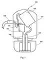
- Fig. 1shows an in-ear earphone 100 according to the prior art: it has a housing 101, an ear cushion 102, which is situated in the auditory canal when worn, and two BA transducers 103, 104.
- the two BA transducersare exposed to signals with the prescribed frequencies by means of a frequency divider network 107 and emit their acoustic waves via sound channels 105 (transducer 103) and 106 (transducer 104), which run essentially parallel to each other and in the direction of the auditory canal.
- Supply of the in-ear earphone 100occurs via a cable with a lead-through 108.
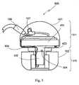
- Fig. 2shows an in-ear earphone 200 according to the prior art: it also has a housing 101, an ear cushion 102, but only one BA transducer 104 with the corresponding sound channel 203.
- the second transduceris a dynamic transducer 202 with corresponding sound channel 201.
- the transducerwas exposed to the signals with the prescribed frequencies by means of a frequency divider network 107.
- the sound channels 201, 203, as in Fig. 1run essentially parallel to each other and in the direction of the auditory canal. Supply of the in-ear earphone 200 with data and energy again occurs via a cable with a lead-through 108.
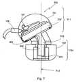
- Fig. 3shows a variant of the prior art according to Fig. 2 with sound channels 106, 201 that discharge, one in the other, which are guided as a common end channel 301 into the area of the ear cushion 102.
- the reference numbers and componentsare otherwise as in Fig. 2 and therefore require no further explanation.
- Fig. 4shows an in-ear earphone 400 according to the invention in a view similar to that of Fig. 1 to 3 , and the same reference numbers are again used for the same or similar components.
- the plug area 410which is situated in the auditory canal during wearing, and the outer area 411 of the earphone 400 are shown in Fig. 4 by parentheses, and it is apparent that they are separated from each other, but need not be, by an indentation.
- the prior artis referred to.
- the earphone 400has a BA transducer 402 and air cushion 102, therefore in the auditory canal, "behind” which a dynamic transducer 201 is provided in whose sound channel 403 the BA transducer 402 lies, whose sound channel is therefore also formed by sound channel 403.
- the geometric miniaturizationis directly apparent from comparison of the figures; as is the excellent coincidence of the two transducers, the actual sound outlet 405 of the BA transducer lying in the sound outlet 403 of the dynamic transducer, see also Fig. 8 .
- the entire cavity lying "in front" of the dynamic transducerwhich is sealed by a seal 404 (through which the control line from the frequency divider network is guided to the BA transducer), becomes the sound channel.
- the sound opening 412 of earphone 400is provided in the plug area, so that it faces the eardrum of the wearer during use of the earphone as intended.
- the BA transducer 402preferably lies next to this sound opening 412.
- Fig. 5shows a variant 500s, which essentially corresponds to the earphone 400 in Fig. 4 , but in which the BA transducer 502 is mounted "inverted", i.e., with the actual sound outlet 504 directed toward the dynamic transducer 202.
- the sound paths of the two transducers 202, 502are practically the same size, which further improves the coincidence and therefore the quality in many cases.
- Fig. 6shows a variant with two BA transducers.
- the sound outlet 504 of transducer 402can also be directed toward transducer 602 here, so that the two sound outlets 404, 604 lie next to each other.
- Fig. 7shows a particularly ergonomic form of the earphone 700, which offers the advantages according to the invention: the dynamic transducer 202 is arranged obliquely to axis 712 of the BA transducer 402, which is also the axis of the ear cushion 102, the common sound channel 703 is designed angled, and can also naturally be bent. In many cases, this increases the wearing comfort and does not reduce the playback quality by the arrangement of the transducers according to the invention. Naturally, the sound outlet 504 of transducer 402 can also be directed here toward transducers 202, so that the coincidence is improved.
- Fig. 8shows a top view in the direction of arrow VIII in Fig. 4 , in which the coincidence of the sound channels 403, 405 is apparent, the BA transducer 402 arranged in sound channel 403 and the ear cushion 102, over whose periphery the housing 401 extends, which is also visible in the area of the central recess of the air cushion.
- Fig. 9finally shows the emitted sound pressure in an artificial ear used for measurement.
- Four curves that correspond to front volumes of 0.1 cm 3 , 0.4 cm 3 , 0.7 cm 3 and 0,9 cm 3are plotted on a logarithmic scale against the frequency between 100 Hz and 20 kHz. It is readily apparent that the maxima of the curves that form at the resonance frequency are shifted to higher frequencies with smaller front volume.
- the inventionis not restricted to the depicted and described practical examples, but can be modified in different ways. Other combinations of individual components, especially other transducers than those stated, are possible, in particular, and the relative dimensions can be chosen differently than those shown, and an additional transducer can be provided, the shape of the sound channels, which were only shown purely schematically, in order to illustrate the arrangement of a transducer according to the invention in the sound channel of the other transducer, can be freely selected over broad limits and the like. If a third transducer is provided, its sound channel can be guided in extra fashion, if it is also preferred that at least the first transducer, and optionally also the second transducer, are arranged in this case, also in the sound channel of the third transducer.
- a frequency divider networkwas shown in each of the drawings, but this is not necessary and the transducers can also be connected simply in parallel with a series.
- the inventiondeals with these things in general, which are only marginally affected by it, and concentrates on the geometric arrangement of several transducers in an in-ear earphone.
- transducerscan be designed, so that they have special sound outlet openings, which, in the preferred embodiments of the invention, when these transducers are arranged as first transducer in the plug area of the in-ear earphone, face the corresponding second transducer, in order to further improve coincidence.
Landscapes
- Engineering & Computer Science (AREA)
- Physics & Mathematics (AREA)
- Acoustics & Sound (AREA)
- Signal Processing (AREA)
- Health & Medical Sciences (AREA)
- General Health & Medical Sciences (AREA)
- Neurosurgery (AREA)
- Otolaryngology (AREA)
- Manufacturing & Machinery (AREA)
- Headphones And Earphones (AREA)
Description
- The invention concerns an in-ear earphone with a plug area, which sits in the auditory canal of the user during its intended wearing, and an outer area, which is the remaining part outside the auditory canal, with at least two transducers, whereby the first transducer, preferably a balanced armature (BA) transducer or a piezoelectric transducer, is provided in an ear cushion in the plug area a sound opening of the earphone and is situated in the sound channel of the second, preferably dynamic, transducer, which is situated in the outer area of the in-ear earphone, wherein the sound channel of the second transducer is sealed by a seal corresponding to
US 5,737,436 A and the introductory part of Claim 1. The part of the in-ear earphone that sits in the auditory canal of the user during its intended wearing is understood to mean the plug area, and the part remaining outside the auditory canal as the outer area. US 5,737,436 A discloses an earphone with a plug part and an outer area which are interconnected by a tubular element. One of the transducers is located within the outer area, its sound channel is the tubular element; the other transducer is located around the tubular member near or in the plug part. The sound "mixing" of the two transducers is rather undefined, only in one pretty exotic embodiment, where the tubular element is used as a kind of acoustic peristaltic pump, the final characteristic is well defined, but in this embodiment, the quality of the transducer itself, using the tube as a membrane, is not good.- In
US 2006/0133631 A , one of the transducers is a balanced armature transducer (BA transducer) and the second transducer a dynamic transducer. Although generally BA transducers and dynamic transducers are discussed subsequently in the description, the invention also includes the use of piezoelectric transducers and any combination of these types of transducers in an in-ear earphone. - The
US 2006/0133631 A very clearly describes the reasons that led to providing in-ear earphones with at least two transducers, and also explains the considerations as to how the sound generated by the transducers is supposed to be guided to the openings in the earphone facing the eardrum. In-ear earphones that were already part of the prior art at the time are also described in this document. An arrangement is also described that has a sound mixing chamber in the area near the plug, therefore near the front most end of the earphone, presumably to achieve better coincidence than in separate sound channels. - The author of this publication sees his invention in the fact that the sound channels of the individual transducers are guided separately to the end of the earphone, mentioning only in passing that when three transducers are provided, two transmit in a common sound channel, which, however, also remain strictly separated from the others.
- It is apparent, both from the figures of this document, which describe the prior art there, and also from the figures that explain the invention there, that, because of the at least two transducers and the tube lines, through which the sound is guided, there is a space requirement, despite all miniaturization of the components, which results in the fact that such in-ear earphones still do not lie in the ear for a good part, but in front of it, which is undesired both for wearing comfort and for optical appearance.
- Generally in-ear earphones are used, on the one hand, as hearing aids, on the other hand for listening to music, telephone conversations, radio communications, radio programs and the like, especially when the environment is not to be exposed to sound or cannot be, or in the case of considerable surrounding noise.
- In principle, it can be assumed that the average volume of an auditory canal is about 1250 mm3 (corresponds to 1.250 cm3) (see, for example: JASA article M.R. Stinson & B.W. Lawton, 1989, Fig. 12). If the device extends about 10 mm into the auditory canal, a remaining volume of about 690 mm3 is left "in front" of it. In a 2-way system according to the prior art, one can reckon with 125 mm3 internal front volume; naturally, these values must be viewed as averages and, in fact, differ from person to person, the corresponding detailed design of the considered device also involving deviations from these values. However, any reduction in front volume is positive, since resonance frequencies are increased on this account and hearing quality improved, and any enlargement of the introduction depth of an in-ear earphone into the auditory canal therefore entails an improvement.
- The objective of the invention is to avoid the mentioned drawbacks and devise an in-ear earphone of the type just mentioned, whose volume and/or front volume are significantly reduced.
- These objectives are achieved according to the invention by the in-ear earphone of claim 1. In this way, not only is the front volume significantly reduced, but a thus far unattainable coincidence of the two transducers relative to the auditory canal is also achieved.
- Through the arrangement according to the invention with saving of sound channels and with positioning of a transducer in the sound channel of the other transducer, the internal front volume is reduced to about 40 mm3. The entire front volume is then reduced from about 815 mm3 to about 713 mm3, which represents a significant improvement relative to the prior art.
- In a further development of the invention, the first transducer, preferably a BA transducer, is incorporated in the earphone, so that its acoustic outlet is adjacent to the acoustic outlet of the second, preferably dynamic transducer, i.e., its acoustic outlet is directed away from the end of the sound channel. A further improvement in coincidence is achieved by this.
- The arrangement according to the invention surprisingly also means that the previous large problems of tight seating of the earphone in the auditory canal is significantly reduced, and that high quality is achieved even with untight seating, since the arrangement according to the invention is less sensitive to leakage than the known ones. The advantage that a pressure compensation opening can be easily provided without significant bass loss goes hand in hand with the use of the dynamic transducer.
- The invention is further explained below by means of the drawing. In the drawing
Figs. 1 to 3 show conventional in-ear earphones according to the prior art,Fig. 4 shows an in-ear earphone according to the invention purely schematically,Fig. 5 to 7 show variants according to the invention,Fig. 8 shows a top view of the transducer ofFig. 4 andFig. 9 shows a comparison of the characteristics of the earphone based on an equivalent circuit with variation of the front volume. Fig. 1 shows an in-ear earphone 100 according to the prior art: it has ahousing 101, anear cushion 102, which is situated in the auditory canal when worn, and twoBA transducers frequency divider network 107 and emit their acoustic waves via sound channels 105 (transducer 103) and 106 (transducer 104), which run essentially parallel to each other and in the direction of the auditory canal. Supply of the in-ear earphone 100 occurs via a cable with a lead-through 108.- Similar to
Fig. 1 ,Fig. 2 shows an in-ear earphone 200 according to the prior art: it also has ahousing 101, anear cushion 102, but only oneBA transducer 104 with thecorresponding sound channel 203. The second transducer is adynamic transducer 202 withcorresponding sound channel 201. In this example, as well, according to the prior art, the transducer was exposed to the signals with the prescribed frequencies by means of afrequency divider network 107. Thesound channels Fig. 1 , run essentially parallel to each other and in the direction of the auditory canal. Supply of the in-ear earphone 200 with data and energy again occurs via a cable with a lead-through 108. Fig. 3 shows a variant of the prior art according toFig. 2 withsound channels common end channel 301 into the area of theear cushion 102. The reference numbers and components are otherwise as inFig. 2 and therefore require no further explanation.Fig. 4 shows an in-ear earphone 400 according to the invention in a view similar to that ofFig. 1 to 3 , and the same reference numbers are again used for the same or similar components.- The
plug area 410, which is situated in the auditory canal during wearing, and theouter area 411 of theearphone 400 are shown inFig. 4 by parentheses, and it is apparent that they are separated from each other, but need not be, by an indentation. The size and form of the indentation or actually an intermediate part, if the variant according toFig. 7 is considered, is only dependent on the design of the earphone, and use of these designations merely serves for easier localization of the component within the earphone in the description and claims, just like the distinction ofplug area 410 andouter area 411, so that no additional reference to the wearer or his auditory canal is necessary. For further embodiments of these areas that are well known to one skilled in the art, the prior art is referred to. - The
earphone 400 has aBA transducer 402 andair cushion 102, therefore in the auditory canal, "behind" which adynamic transducer 201 is provided in whosesound channel 403 theBA transducer 402 lies, whose sound channel is therefore also formed bysound channel 403. The geometric miniaturization is directly apparent from comparison of the figures; as is the excellent coincidence of the two transducers, theactual sound outlet 405 of the BA transducer lying in thesound outlet 403 of the dynamic transducer, see alsoFig. 8 . The entire cavity lying "in front" of the dynamic transducer which is sealed by a seal 404 (through which the control line from the frequency divider network is guided to the BA transducer), becomes the sound channel. - The sound opening 412 of
earphone 400 is provided in the plug area, so that it faces the eardrum of the wearer during use of the earphone as intended. TheBA transducer 402 preferably lies next to this sound opening 412. Fig. 5 shows a variant 500s, which essentially corresponds to theearphone 400 inFig. 4 , but in which theBA transducer 502 is mounted "inverted", i.e., with theactual sound outlet 504 directed toward thedynamic transducer 202. In this way, the sound paths of the twotransducers Fig. 6 shows a variant with two BA transducers. Naturally, thesound outlet 504 oftransducer 402 can also be directed towardtransducer 602 here, so that the twosound outlets Fig. 7 shows a particularly ergonomic form of theearphone 700, which offers the advantages according to the invention: thedynamic transducer 202 is arranged obliquely toaxis 712 of theBA transducer 402, which is also the axis of theear cushion 102, thecommon sound channel 703 is designed angled, and can also naturally be bent. In many cases, this increases the wearing comfort and does not reduce the playback quality by the arrangement of the transducers according to the invention. Naturally, thesound outlet 504 oftransducer 402 can also be directed here towardtransducers 202, so that the coincidence is improved.Fig. 8 shows a top view in the direction of arrow VIII inFig. 4 , in which the coincidence of thesound channels BA transducer 402 arranged insound channel 403 and theear cushion 102, over whose periphery thehousing 401 extends, which is also visible in the area of the central recess of the air cushion.Fig. 9 finally shows the emitted sound pressure in an artificial ear used for measurement. Four curves that correspond to front volumes of 0.1 cm3, 0.4 cm3, 0.7 cm3 and 0,9 cm3 are plotted on a logarithmic scale against the frequency between 100 Hz and 20 kHz. It is readily apparent that the maxima of the curves that form at the resonance frequency are shifted to higher frequencies with smaller front volume.- The invention is not restricted to the depicted and described practical examples, but can be modified in different ways. Other combinations of individual components, especially other transducers than those stated, are possible, in particular, and the relative dimensions can be chosen differently than those shown, and an additional transducer can be provided, the shape of the sound channels, which were only shown purely schematically, in order to illustrate the arrangement of a transducer according to the invention in the sound channel of the other transducer, can be freely selected over broad limits and the like. If a third transducer is provided, its sound channel can be guided in extra fashion, if it is also preferred that at least the first transducer, and optionally also the second transducer, are arranged in this case, also in the sound channel of the third transducer.
- A frequency divider network was shown in each of the drawings, but this is not necessary and the transducers can also be connected simply in parallel with a series. The invention deals with these things in general, which are only marginally affected by it, and concentrates on the geometric arrangement of several transducers in an in-ear earphone.
- All three types of transducers can be designed, so that they have special sound outlet openings, which, in the preferred embodiments of the invention, when these transducers are arranged as first transducer in the plug area of the in-ear earphone, face the corresponding second transducer, in order to further improve coincidence.
- All materials used in the prior art for in-ear earphones can be used as materials for the in-ear earphone according to the invention, as can all manufacturing techniques that increase the application possibilities for the invention.
Claims (5)
- In-ear earphone with a plug area (410, 510, 610, 710), which is adapted to sit in an auditory canal of a user during its intended wearing, and an outer area (411, 511, 611, 711), which is a part of the in-ear earphone remaining outside the auditory canal during the intended wearing, with a frequency divider network and with at least a first and second transducer, whereby the first transducer (402, 502), preferably a balanced armature (BA) transducer or a piezoelectric transducer, is provided in an ear cushion (102) in the plug area (410, 510, 610, 710), the ear cushion having a sound opening (412) of the earphone (400, 500, 600, 700) and is situated in a sound channel (403, 703) of the second, preferably dynamic, transducer (202, 602), which is situated in the outer area (411, 511, 611, 711) of the in-ear earphone, wherein the sound channel (403, 703) of the second transducer (202, 602) is sealed by a seal (404), andcharacterized in that a control line from the frequency divider network (107) is guided through the seal (404) and within the sound channel (403, 703) to the first transducer (402, 502).
- In-ear earphone according to Claim 1,characterized in that the sound outlet (504) of the first transducer (502) faces the second transducer (202, 602).
- In-ear earphone according to one of the preceding claims,characterized in that the sound channel (703) is angled or bent.
- In-ear earphone according to one of the preceding claims,characterized in that the first transducer (402, 502) lies adjacent to the sound opening (412) of the earphone (400, 500, 600, 700).
- In-ear earphone according to one of the preceding claims,characterized in that at least the first transducer (402, 502) is arranged in the sound channel of an optionally provided third or additional transducer.
Priority Applications (4)
| Application Number | Priority Date | Filing Date | Title |
|---|---|---|---|
| EP08450034AEP2101512B1 (en) | 2008-03-12 | 2008-03-12 | In-ear earphone with multiple transducers |
| JP2009058704AJP5528715B2 (en) | 2008-03-12 | 2009-03-11 | In-ear earphone |
| CN200910127446XACN101534461B (en) | 2008-03-12 | 2009-03-11 | In-ear earphone with multiple transducers |
| US12/402,101US8311259B2 (en) | 2008-03-12 | 2009-03-11 | In-ear earphone |
Applications Claiming Priority (1)
| Application Number | Priority Date | Filing Date | Title |
|---|---|---|---|
| EP08450034AEP2101512B1 (en) | 2008-03-12 | 2008-03-12 | In-ear earphone with multiple transducers |
Publications (2)
| Publication Number | Publication Date |
|---|---|
| EP2101512A1 EP2101512A1 (en) | 2009-09-16 |
| EP2101512B1true EP2101512B1 (en) | 2012-07-18 |
Family
ID=39493549
Family Applications (1)
| Application Number | Title | Priority Date | Filing Date |
|---|---|---|---|
| EP08450034AActiveEP2101512B1 (en) | 2008-03-12 | 2008-03-12 | In-ear earphone with multiple transducers |
Country Status (4)
| Country | Link |
|---|---|
| US (1) | US8311259B2 (en) |
| EP (1) | EP2101512B1 (en) |
| JP (1) | JP5528715B2 (en) |
| CN (1) | CN101534461B (en) |
Cited By (1)
| Publication number | Priority date | Publication date | Assignee | Title |
|---|---|---|---|---|
| RU2680663C2 (en)* | 2017-08-08 | 2019-02-25 | Михаил Викторович Кучеренко | In-ear headphone |
Families Citing this family (25)
| Publication number | Priority date | Publication date | Assignee | Title |
|---|---|---|---|---|
| EP2306755B1 (en) | 2009-09-03 | 2015-06-03 | AKG Acoustics GmbH | In-ear earphone |
| US8549733B2 (en)* | 2010-07-09 | 2013-10-08 | Shure Acquisition Holdings, Inc. | Method of forming a transducer assembly |
| US8548186B2 (en)* | 2010-07-09 | 2013-10-01 | Shure Acquisition Holdings, Inc. | Earphone assembly |
| US8538061B2 (en) | 2010-07-09 | 2013-09-17 | Shure Acquisition Holdings, Inc. | Earphone driver and method of manufacture |
| US9042585B2 (en)* | 2010-12-01 | 2015-05-26 | Creative Technology Ltd | Method for optimizing performance of a multi-transducer earpiece and a multi-transducer earpiece |
| US8954177B2 (en)* | 2011-06-01 | 2015-02-10 | Apple Inc. | Controlling operation of a media device based upon whether a presentation device is currently being worn by a user |
| KR101236082B1 (en) | 2011-09-21 | 2013-02-21 | 부전전자 주식회사 | earphone |
| KR101920029B1 (en)* | 2012-08-03 | 2018-11-19 | 삼성전자주식회사 | Mobile apparatus and control method thereof |
| CN203378015U (en)* | 2012-12-13 | 2014-01-01 | 捷音特科技股份有限公司 | Double-frequency coaxial earphone |
| US9113254B2 (en) | 2013-08-05 | 2015-08-18 | Google Technology Holdings LLC | Earbud with pivoting acoustic duct |
| WO2015022817A1 (en)* | 2013-08-12 | 2015-02-19 | ソニー株式会社 | Headphone and acoustic characteristic adjustment method |
| EP3073758B1 (en)* | 2013-11-19 | 2021-05-19 | Sony Corporation | Headphone and acoustic characteristic adjustment method |
| TWM492586U (en)* | 2014-06-18 | 2014-12-21 | Jetvox Acoustic Corp | Piezoelectric speaker |
| US9961434B2 (en) | 2014-12-31 | 2018-05-01 | Skullcandy, Inc. | In-ear headphones having a flexible nozzle and related methods |
| US10582284B2 (en) | 2015-09-30 | 2020-03-03 | Apple Inc. | In-ear headphone |
| KR101713174B1 (en)* | 2015-11-11 | 2017-03-08 | 주식회사 알머스 | Earphone using dynamic speaker and piezoelectric speaker |
| CN106792304A (en)* | 2015-11-21 | 2017-05-31 | 王永明 | A kind of multi-driver in-ear earphone |
| TWI596952B (en)* | 2016-03-21 | 2017-08-21 | 固昌通訊股份有限公司 | In-ear earphone |
| CN105959851B (en)* | 2016-06-14 | 2019-04-19 | 常州市武进晶丰电子有限公司 | In-Ear high pitch compensates earphone |
| CN106060751B (en)* | 2016-07-18 | 2022-04-15 | 青岛歌尔声学科技有限公司 | Audio test tool for headset |
| JP6619706B2 (en)* | 2016-07-29 | 2019-12-11 | 株式会社オーディオテクニカ | earphone |
| EP3588980B1 (en) | 2018-06-25 | 2021-06-02 | Sonova AG | Ite hearing device |
| US10924838B1 (en)* | 2019-09-11 | 2021-02-16 | Bose Corporation | Audio device |
| US20250113134A1 (en) | 2023-09-29 | 2025-04-03 | Sound Devices Llc | Bidirectional multi-channel audio link for transducers |
| WO2025199742A1 (en)* | 2024-03-26 | 2025-10-02 | Harman International Industries , Incorporated | Earphone |
Family Cites Families (17)
| Publication number | Priority date | Publication date | Assignee | Title |
|---|---|---|---|---|
| US3983336A (en)* | 1974-10-15 | 1976-09-28 | Hooshang Malek | Directional self containing ear mounted hearing aid |
| JP2516904B2 (en)* | 1985-08-24 | 1996-07-24 | 松下電器産業株式会社 | Headphone |
| JPS6268400U (en)* | 1985-10-18 | 1987-04-28 | ||
| DE3736591C3 (en)* | 1987-04-13 | 1994-04-14 | Beltone Electronics Corp | Hearing aid with ear wax protection |
| JPH0244899A (en)* | 1988-08-04 | 1990-02-14 | Matsushita Electric Ind Co Ltd | Inner-ear type head phone |
| US5692059A (en)* | 1995-02-24 | 1997-11-25 | Kruger; Frederick M. | Two active element in-the-ear microphone system |
| AU7154196A (en) | 1995-09-19 | 1997-04-09 | Interval Research Corporation | Earphones with eyeglass attachments |
| JP4151157B2 (en)* | 1999-05-31 | 2008-09-17 | ソニー株式会社 | earphone |
| US7317806B2 (en)* | 2004-12-22 | 2008-01-08 | Ultimate Ears, Llc | Sound tube tuned multi-driver earpiece |
| US7263195B2 (en) | 2004-12-22 | 2007-08-28 | Ultimate Ears, Llc | In-ear monitor with shaped dual bore |
| US7194102B2 (en)* | 2004-12-22 | 2007-03-20 | Ultimate Ears, Llc | In-ear monitor with hybrid dual diaphragm and single armature design |
| US7634099B2 (en)* | 2005-07-22 | 2009-12-15 | Logitech International, S.A. | High-fidelity earpiece with adjustable frequency response |
| US8031900B2 (en)* | 2006-02-27 | 2011-10-04 | Logitech International, S.A. | Earphone ambient eartip |
| US7680292B2 (en)* | 2006-05-30 | 2010-03-16 | Knowles Electronics, Llc | Personal listening device |
| US8170249B2 (en)* | 2006-06-19 | 2012-05-01 | Sonion Nederland B.V. | Hearing aid having two receivers each amplifying a different frequency range |
| US8135163B2 (en)* | 2007-08-30 | 2012-03-13 | Klipsch Group, Inc. | Balanced armature with acoustic low pass filter |
| US8238596B2 (en)* | 2007-12-10 | 2012-08-07 | Klipsch Group, Inc. | In-ear headphones |
- 2008
- 2008-03-12EPEP08450034Apatent/EP2101512B1/enactiveActive
- 2009
- 2009-03-11CNCN200910127446XApatent/CN101534461B/enactiveActive
- 2009-03-11JPJP2009058704Apatent/JP5528715B2/ennot_activeExpired - Fee Related
- 2009-03-11USUS12/402,101patent/US8311259B2/enactiveActive
Cited By (1)
| Publication number | Priority date | Publication date | Assignee | Title |
|---|---|---|---|---|
| RU2680663C2 (en)* | 2017-08-08 | 2019-02-25 | Михаил Викторович Кучеренко | In-ear headphone |
Also Published As
| Publication number | Publication date |
|---|---|
| CN101534461B (en) | 2013-10-30 |
| JP5528715B2 (en) | 2014-06-25 |
| CN101534461A (en) | 2009-09-16 |
| JP2009219122A (en) | 2009-09-24 |
| EP2101512A1 (en) | 2009-09-16 |
| US20090232341A1 (en) | 2009-09-17 |
| US8311259B2 (en) | 2012-11-13 |
Similar Documents
| Publication | Publication Date | Title |
|---|---|---|
| EP2101512B1 (en) | In-ear earphone with multiple transducers | |
| JP5695703B2 (en) | Earphone with acoustic tuning mechanism | |
| CN104396276B (en) | Headphones with controlled sound leak ports | |
| CN107950034B (en) | Noise reduction for in-ear headphones | |
| US8139806B2 (en) | Earphone for placement in an ear | |
| JP2024501575A (en) | sound output device | |
| EP3637799B1 (en) | Hearing device comprising a housing with a venting passage | |
| US11792564B2 (en) | Hearing device comprising a vent and an acoustic valve | |
| CN107018458B (en) | Earphone set | |
| JP5849296B1 (en) | Sealed earphone with communication part | |
| JP5872722B1 (en) | Earphone with communication pipe | |
| KR100633050B1 (en) | earphone | |
| CN118104251B (en) | Open earphone | |
| KR102778130B1 (en) | An assembly comprising a sensor in a spout | |
| AU2019284040B2 (en) | An earphone having an acoustic tuning mechanism | |
| JP2016201786A (en) | Earphone with communicating tube | |
| HK40037850A (en) | An earphone having an acoustic tuning mechanism | |
| HK1208111B (en) | An earphone having a controlled acoustic leak port | |
| HK1193689B (en) | An earphone having an acoustic tuning mechanism |
Legal Events
| Date | Code | Title | Description |
|---|---|---|---|
| PUAI | Public reference made under article 153(3) epc to a published international application that has entered the european phase | Free format text:ORIGINAL CODE: 0009012 | |
| AK | Designated contracting states | Kind code of ref document:A1 Designated state(s):AT BE BG CH CY CZ DE DK EE ES FI FR GB GR HR HU IE IS IT LI LT LU LV MC MT NL NO PL PT RO SE SI SK TR | |
| AX | Request for extension of the european patent | Extension state:AL BA MK RS | |
| 17P | Request for examination filed | Effective date:20100316 | |
| 17Q | First examination report despatched | Effective date:20100413 | |
| AKX | Designation fees paid | Designated state(s):AT DE FR GB IE | |
| RIC1 | Information provided on ipc code assigned before grant | Ipc:H04R 1/10 20060101AFI20111028BHEP Ipc:H04R 25/00 20060101ALI20111028BHEP | |
| GRAP | Despatch of communication of intention to grant a patent | Free format text:ORIGINAL CODE: EPIDOSNIGR1 | |
| GRAS | Grant fee paid | Free format text:ORIGINAL CODE: EPIDOSNIGR3 | |
| GRAA | (expected) grant | Free format text:ORIGINAL CODE: 0009210 | |
| AK | Designated contracting states | Kind code of ref document:B1 Designated state(s):AT DE FR GB IE | |
| REG | Reference to a national code | Ref country code:GB Ref legal event code:FG4D | |
| REG | Reference to a national code | Ref country code:AT Ref legal event code:REF Ref document number:567291 Country of ref document:AT Kind code of ref document:T Effective date:20120815 Ref country code:IE Ref legal event code:FG4D | |
| REG | Reference to a national code | Ref country code:DE Ref legal event code:R096 Ref document number:602008017264 Country of ref document:DE Effective date:20120913 | |
| PLBE | No opposition filed within time limit | Free format text:ORIGINAL CODE: 0009261 | |
| STAA | Information on the status of an ep patent application or granted ep patent | Free format text:STATUS: NO OPPOSITION FILED WITHIN TIME LIMIT | |
| 26N | No opposition filed | Effective date:20130419 | |
| REG | Reference to a national code | Ref country code:DE Ref legal event code:R097 Ref document number:602008017264 Country of ref document:DE Effective date:20130419 | |
| REG | Reference to a national code | Ref country code:GB Ref legal event code:732E Free format text:REGISTERED BETWEEN 20140710 AND 20140716 | |
| REG | Reference to a national code | Ref country code:FR Ref legal event code:TP Owner name:HARMAN INTERNATIONAL INDUSTRIES, INCORPORATED, US Effective date:20140902 | |
| REG | Reference to a national code | Ref country code:FR Ref legal event code:PLFP Year of fee payment:9 | |
| REG | Reference to a national code | Ref country code:GB Ref legal event code:732E Free format text:REGISTERED BETWEEN 20160303 AND 20160309 | |
| REG | Reference to a national code | Ref country code:DE Ref legal event code:R081 Ref document number:602008017264 Country of ref document:DE Owner name:APPLE INC., CUPERTINO, US Free format text:FORMER OWNER: AKG ACOUSTICS GMBH, WIEN, AT | |
| REG | Reference to a national code | Ref country code:FR Ref legal event code:TP Owner name:APPLE INC., US Effective date:20160707 | |
| REG | Reference to a national code | Ref country code:FR Ref legal event code:PLFP Year of fee payment:10 | |
| REG | Reference to a national code | Ref country code:FR Ref legal event code:PLFP Year of fee payment:11 | |
| PGFP | Annual fee paid to national office [announced via postgrant information from national office to epo] | Ref country code:AT Payment date:20200225 Year of fee payment:13 | |
| REG | Reference to a national code | Ref country code:AT Ref legal event code:MM01 Ref document number:567291 Country of ref document:AT Kind code of ref document:T Effective date:20210312 | |
| PG25 | Lapsed in a contracting state [announced via postgrant information from national office to epo] | Ref country code:AT Free format text:LAPSE BECAUSE OF NON-PAYMENT OF DUE FEES Effective date:20210312 | |
| PGFP | Annual fee paid to national office [announced via postgrant information from national office to epo] | Ref country code:IE Payment date:20220110 Year of fee payment:15 | |
| PGFP | Annual fee paid to national office [announced via postgrant information from national office to epo] | Ref country code:FR Payment date:20220118 Year of fee payment:15 | |
| P01 | Opt-out of the competence of the unified patent court (upc) registered | Effective date:20230526 | |
| REG | Reference to a national code | Ref country code:IE Ref legal event code:MM4A | |
| PG25 | Lapsed in a contracting state [announced via postgrant information from national office to epo] | Ref country code:IE Free format text:LAPSE BECAUSE OF NON-PAYMENT OF DUE FEES Effective date:20230312 Ref country code:FR Free format text:LAPSE BECAUSE OF NON-PAYMENT OF DUE FEES Effective date:20230331 | |
| PGFP | Annual fee paid to national office [announced via postgrant information from national office to epo] | Ref country code:DE Payment date:20241231 Year of fee payment:18 | |
| PGFP | Annual fee paid to national office [announced via postgrant information from national office to epo] | Ref country code:GB Payment date:20250102 Year of fee payment:18 |