EP2099393B1 - Bifurcated stent with variable length branches - Google Patents
Bifurcated stent with variable length branchesDownload PDFInfo
- Publication number
- EP2099393B1 EP2099393B1EP07845096AEP07845096AEP2099393B1EP 2099393 B1EP2099393 B1EP 2099393B1EP 07845096 AEP07845096 AEP 07845096AEP 07845096 AEP07845096 AEP 07845096AEP 2099393 B1EP2099393 B1EP 2099393B1
- Authority
- EP
- European Patent Office
- Prior art keywords
- branch
- longitudinally extendable
- cylindrical rings
- extendable portion
- rings
- Prior art date
- Legal status (The legal status is an assumption and is not a legal conclusion. Google has not performed a legal analysis and makes no representation as to the accuracy of the status listed.)
- Ceased
Links
- 230000008878couplingEffects0.000claimsdescription7
- 238000010168coupling processMethods0.000claimsdescription7
- 238000005859coupling reactionMethods0.000claimsdescription7
- 238000009434installationMethods0.000claims4
- 238000000034methodMethods0.000abstractdescription15
- 238000004804windingMethods0.000abstractdescription2
- 208000031481Pathologic ConstrictionDiseases0.000description27
- 208000037804stenosisDiseases0.000description23
- 230000036262stenosisEffects0.000description23
- -1poly(hydroxybutyrate)Polymers0.000description12
- 210000004204blood vesselAnatomy0.000description11
- 239000000126substanceSubstances0.000description8
- PXHVJJICTQNCMI-UHFFFAOYSA-NNickelChemical compound[Ni]PXHVJJICTQNCMI-UHFFFAOYSA-N0.000description6
- 230000001225therapeutic effectEffects0.000description6
- 238000002399angioplastyMethods0.000description4
- 239000003795chemical substances by applicationSubstances0.000description4
- VYZAMTAEIAYCRO-UHFFFAOYSA-NChromiumChemical compound[Cr]VYZAMTAEIAYCRO-UHFFFAOYSA-N0.000description3
- ZOKXTWBITQBERF-UHFFFAOYSA-NMolybdenumChemical compound[Mo]ZOKXTWBITQBERF-UHFFFAOYSA-N0.000description3
- NWIBSHFKIJFRCO-WUDYKRTCSA-NMytomycinChemical compoundC1N2C(C(C(C)=C(N)C3=O)=O)=C3[C@@H](COC(N)=O)[C@@]2(OC)[C@@H]2[C@H]1N2NWIBSHFKIJFRCO-WUDYKRTCSA-N0.000description3
- KDLHZDBZIXYQEI-UHFFFAOYSA-NPalladiumChemical compound[Pd]KDLHZDBZIXYQEI-UHFFFAOYSA-N0.000description3
- 102000010780Platelet-Derived Growth FactorHuman genes0.000description3
- 108010038512Platelet-Derived Growth FactorProteins0.000description3
- 239000003146anticoagulant agentSubstances0.000description3
- 239000004019antithrombinSubstances0.000description3
- 239000011651chromiumSubstances0.000description3
- 239000000463materialSubstances0.000description3
- 239000011733molybdenumSubstances0.000description3
- 230000037361pathwayEffects0.000description3
- 229920000642polymerPolymers0.000description3
- IAKHMKGGTNLKSZ-INIZCTEOSA-N(S)-colchicineChemical compoundC1([C@@H](NC(C)=O)CC2)=CC(=O)C(OC)=CC=C1C1=C2C=C(OC)C(OC)=C1OCIAKHMKGGTNLKSZ-INIZCTEOSA-N0.000description2
- AOJJSUZBOXZQNB-TZSSRYMLSA-NDoxorubicinChemical compoundO([C@H]1C[C@@](O)(CC=2C(O)=C3C(=O)C=4C=CC=C(C=4C(=O)C3=C(O)C=21)OC)C(=O)CO)[C@H]1C[C@H](N)[C@H](O)[C@H](C)O1AOJJSUZBOXZQNB-TZSSRYMLSA-N0.000description2
- OHCQJHSOBUTRHG-KGGHGJDLSA-NFORSKOLINChemical compoundO=C([C@@]12O)C[C@](C)(C=C)O[C@]1(C)[C@@H](OC(=O)C)[C@@H](O)[C@@H]1[C@]2(C)[C@@H](O)CCC1(C)COHCQJHSOBUTRHG-KGGHGJDLSA-N0.000description2
- 102000009123FibrinHuman genes0.000description2
- 108010073385FibrinProteins0.000description2
- BWGVNKXGVNDBDI-UHFFFAOYSA-NFibrin monomerChemical compoundCNC(=O)CNC(=O)CNBWGVNKXGVNDBDI-UHFFFAOYSA-N0.000description2
- 102000018233Fibroblast Growth FactorHuman genes0.000description2
- 108050007372Fibroblast Growth FactorProteins0.000description2
- JVTAAEKCZFNVCJ-REOHCLBHSA-NL-lactic acidChemical compoundC[C@H](O)C(O)=OJVTAAEKCZFNVCJ-REOHCLBHSA-N0.000description2
- 108010007859LisinoprilProteins0.000description2
- PCZOHLXUXFIOCF-UHFFFAOYSA-NMonacolin XNatural productsC12C(OC(=O)C(C)CC)CC(C)C=C2C=CC(C)C1CCC1CC(O)CC(=O)O1PCZOHLXUXFIOCF-UHFFFAOYSA-N0.000description2
- ZDZOTLJHXYCWBA-VCVYQWHSSA-NN-debenzoyl-N-(tert-butoxycarbonyl)-10-deacetyltaxolChemical compoundO([C@H]1[C@H]2[C@@](C([C@H](O)C3=C(C)[C@@H](OC(=O)[C@H](O)[C@@H](NC(=O)OC(C)(C)C)C=4C=CC=CC=4)C[C@]1(O)C3(C)C)=O)(C)[C@@H](O)C[C@H]1OC[C@]12OC(=O)C)C(=O)C1=CC=CC=C1ZDZOTLJHXYCWBA-VCVYQWHSSA-N0.000description2
- MWUXSHHQAYIFBG-UHFFFAOYSA-NNitric oxideChemical compoundO=[N]MWUXSHHQAYIFBG-UHFFFAOYSA-N0.000description2
- 210000003484anatomyAnatomy0.000description2
- 239000005557antagonistSubstances0.000description2
- 230000002927anti-mitotic effectEffects0.000description2
- 230000000118anti-neoplastic effectEffects0.000description2
- 230000000702anti-platelet effectEffects0.000description2
- 230000001028anti-proliverative effectEffects0.000description2
- 229940127219anticoagulant drugDrugs0.000description2
- FAKRSMQSSFJEIM-RQJHMYQMSA-NcaptoprilChemical compoundSC[C@@H](C)C(=O)N1CCC[C@H]1C(O)=OFAKRSMQSSFJEIM-RQJHMYQMSA-N0.000description2
- 229910052804chromiumInorganic materials0.000description2
- 239000011248coating agentSubstances0.000description2
- 238000000576coating methodMethods0.000description2
- 229910017052cobaltInorganic materials0.000description2
- 239000010941cobaltSubstances0.000description2
- GUTLYIVDDKVIGB-UHFFFAOYSA-Ncobalt atomChemical compound[Co]GUTLYIVDDKVIGB-UHFFFAOYSA-N0.000description2
- 238000010276constructionMethods0.000description2
- 229950003499fibrinDrugs0.000description2
- 229940126864fibroblast growth factorDrugs0.000description2
- 229920000669heparinPolymers0.000description2
- WQPDUTSPKFMPDP-OUMQNGNKSA-NhirudinChemical compoundC([C@@H](C(=O)N[C@@H](CCC(O)=O)C(=O)N[C@@H](CCC(O)=O)C(=O)N[C@@H]([C@@H](C)CC)C(=O)N1[C@@H](CCC1)C(=O)N[C@@H](CCC(O)=O)C(=O)N[C@@H](CCC(O)=O)C(=O)N[C@@H](CC=1C=CC(OS(O)(=O)=O)=CC=1)C(=O)N[C@@H](CC(C)C)C(=O)N[C@@H](CCC(N)=O)C(O)=O)NC(=O)[C@H](CC(O)=O)NC(=O)CNC(=O)[C@H](CC(O)=O)NC(=O)[C@H](CC(N)=O)NC(=O)[C@H](CC=1NC=NC=1)NC(=O)[C@H](CO)NC(=O)[C@H](CCC(N)=O)NC(=O)[C@H]1N(CCC1)C(=O)[C@H](CCCCN)NC(=O)[C@H]1N(CCC1)C(=O)[C@@H](NC(=O)CNC(=O)[C@H](CCC(O)=O)NC(=O)CNC(=O)[C@@H](NC(=O)[C@@H](NC(=O)[C@H]1NC(=O)[C@H](CCC(N)=O)NC(=O)[C@H](CC(N)=O)NC(=O)[C@H](CCCCN)NC(=O)[C@H](CCC(O)=O)NC(=O)CNC(=O)[C@H](CC(O)=O)NC(=O)[C@H](CO)NC(=O)CNC(=O)[C@H](CC(C)C)NC(=O)[C@H]([C@@H](C)CC)NC(=O)[C@@H]2CSSC[C@@H](C(=O)N[C@@H](CCC(O)=O)C(=O)NCC(=O)N[C@@H](CO)C(=O)N[C@@H](CC(N)=O)C(=O)N[C@H](C(=O)N[C@H](C(NCC(=O)N[C@@H](CCC(N)=O)C(=O)NCC(=O)N[C@@H](CC(N)=O)C(=O)N[C@@H](CCCCN)C(=O)N2)=O)CSSC1)C(C)C)NC(=O)[C@H](CC(C)C)NC(=O)[C@H]1NC(=O)[C@H](CC(C)C)NC(=O)[C@H](CC(N)=O)NC(=O)[C@H](CCC(N)=O)NC(=O)CNC(=O)[C@H](CO)NC(=O)[C@H](CCC(O)=O)NC(=O)[C@H]([C@@H](C)O)NC(=O)[C@@H](NC(=O)[C@H](CC(O)=O)NC(=O)[C@@H](NC(=O)[C@H](CC=2C=CC(O)=CC=2)NC(=O)[C@@H](NC(=O)[C@@H](N)C(C)C)C(C)C)[C@@H](C)O)CSSC1)C(C)C)[C@@H](C)O)[C@@H](C)O)C1=CC=CC=C1WQPDUTSPKFMPDP-OUMQNGNKSA-N0.000description2
- 239000003112inhibitorSubstances0.000description2
- 238000003780insertionMethods0.000description2
- 230000037431insertionEffects0.000description2
- RLAWWYSOJDYHDC-BZSNNMDCSA-NlisinoprilChemical compoundC([C@H](N[C@@H](CCCCN)C(=O)N1[C@@H](CCC1)C(O)=O)C(O)=O)CC1=CC=CC=C1RLAWWYSOJDYHDC-BZSNNMDCSA-N0.000description2
- PCZOHLXUXFIOCF-BXMDZJJMSA-NlovastatinChemical compoundC([C@H]1[C@@H](C)C=CC2=C[C@H](C)C[C@@H]([C@H]12)OC(=O)[C@@H](C)CC)C[C@@H]1C[C@@H](O)CC(=O)O1PCZOHLXUXFIOCF-BXMDZJJMSA-N0.000description2
- 238000004519manufacturing processMethods0.000description2
- 229960004857mitomycinDrugs0.000description2
- 229910052750molybdenumInorganic materials0.000description2
- 229910052759nickelInorganic materials0.000description2
- 229910001000nickel titaniumInorganic materials0.000description2
- 230000001575pathological effectEffects0.000description2
- 229920001610polycaprolactonePolymers0.000description2
- 239000004632polycaprolactoneSubstances0.000description2
- 229920002635polyurethanePolymers0.000description2
- 239000004814polyurethaneSubstances0.000description2
- 230000002285radioactive effectEffects0.000description2
- QZAYGJVTTNCVMB-UHFFFAOYSA-NserotoninChemical compoundC1=C(O)C=C2C(CCN)=CNC2=C1QZAYGJVTTNCVMB-UHFFFAOYSA-N0.000description2
- KWPACVJPAFGBEQ-IKGGRYGDSA-N(2s)-1-[(2r)-2-amino-3-phenylpropanoyl]-n-[(3s)-1-chloro-6-(diaminomethylideneamino)-2-oxohexan-3-yl]pyrrolidine-2-carboxamideChemical compoundC([C@@H](N)C(=O)N1[C@@H](CCC1)C(=O)N[C@@H](CCCNC(N)=N)C(=O)CCl)C1=CC=CC=C1KWPACVJPAFGBEQ-IKGGRYGDSA-N0.000description1
- PUDHBTGHUJUUFI-SCTWWAJVSA-N(4r,7s,10s,13r,16s,19r)-10-(4-aminobutyl)-n-[(2s,3r)-1-amino-3-hydroxy-1-oxobutan-2-yl]-19-[[(2r)-2-amino-3-naphthalen-2-ylpropanoyl]amino]-16-[(4-hydroxyphenyl)methyl]-13-(1h-indol-3-ylmethyl)-6,9,12,15,18-pentaoxo-7-propan-2-yl-1,2-dithia-5,8,11,14,17-pChemical compoundC([C@H]1C(=O)N[C@H](CC=2C3=CC=CC=C3NC=2)C(=O)N[C@@H](CCCCN)C(=O)N[C@H](C(N[C@@H](CSSC[C@@H](C(=O)N1)NC(=O)[C@H](N)CC=1C=C2C=CC=CC2=CC=1)C(=O)N[C@@H]([C@@H](C)O)C(N)=O)=O)C(C)C)C1=CC=C(O)C=C1PUDHBTGHUJUUFI-SCTWWAJVSA-N0.000description1
- GQGRDYWMOPRROR-ZIFKCHSBSA-N(e)-7-[(1r,2r,3s,5s)-3-hydroxy-5-[(4-phenylphenyl)methoxy]-2-piperidin-1-ylcyclopentyl]hept-4-enoic acidChemical compoundO([C@H]1C[C@@H]([C@@H]([C@H]1CC\C=C\CCC(O)=O)N1CCCCC1)O)CC(C=C1)=CC=C1C1=CC=CC=C1GQGRDYWMOPRROR-ZIFKCHSBSA-N0.000description1
- SFIUYASDNWEYDB-HHQFNNIRSA-N6-chloro-1,1-dioxo-3,4-dihydro-2h-1$l^{6},2,4-benzothiadiazine-7-sulfonamide;(2s)-1-[(2s)-2-methyl-3-sulfanylpropanoyl]pyrrolidine-2-carboxylic acidChemical compoundSC[C@@H](C)C(=O)N1CCC[C@H]1C(O)=O.C1=C(Cl)C(S(=O)(=O)N)=CC2=C1NCNS2(=O)=OSFIUYASDNWEYDB-HHQFNNIRSA-N0.000description1
- ZCYVEMRRCGMTRW-UHFFFAOYSA-N7553-56-2Chemical compound[I]ZCYVEMRRCGMTRW-UHFFFAOYSA-N0.000description1
- 239000005541ACE inhibitorSubstances0.000description1
- 229940127291Calcium channel antagonistDrugs0.000description1
- BVKZGUZCCUSVTD-UHFFFAOYSA-LCarbonateChemical compound[O-]C([O-])=OBVKZGUZCCUSVTD-UHFFFAOYSA-L0.000description1
- JZUFKLXOESDKRF-UHFFFAOYSA-NChlorothiazideChemical compoundC1=C(Cl)C(S(=O)(=O)N)=CC2=C1NCNS2(=O)=OJZUFKLXOESDKRF-UHFFFAOYSA-N0.000description1
- 229910000531Co alloyInorganic materials0.000description1
- 102000008186CollagenHuman genes0.000description1
- 108010035532CollagenProteins0.000description1
- 229910000599Cr alloyInorganic materials0.000description1
- 229920001651CyanoacrylatePolymers0.000description1
- SUZLHDUTVMZSEV-UHFFFAOYSA-NDeoxycoleonolNatural productsC12C(=O)CC(C)(C=C)OC2(C)C(OC(=O)C)C(O)C2C1(C)C(O)CCC2(C)CSUZLHDUTVMZSEV-UHFFFAOYSA-N0.000description1
- 229920002307DextranPolymers0.000description1
- MWWSFMDVAYGXBV-RUELKSSGSA-NDoxorubicin hydrochlorideChemical compoundCl.O([C@H]1C[C@@](O)(CC=2C(O)=C3C(=O)C=4C=CC=C(C=4C(=O)C3=C(O)C=21)OC)C(=O)CO)[C@H]1C[C@H](N)[C@H](O)[C@H](C)O1MWWSFMDVAYGXBV-RUELKSSGSA-N0.000description1
- JOYRKODLDBILNP-UHFFFAOYSA-NEthyl urethaneChemical compoundCCOC(N)=OJOYRKODLDBILNP-UHFFFAOYSA-N0.000description1
- 108010049003FibrinogenProteins0.000description1
- 102000008946FibrinogenHuman genes0.000description1
- GHASVSINZRGABV-UHFFFAOYSA-NFluorouracilChemical compoundFC1=CNC(=O)NC1=OGHASVSINZRGABV-UHFFFAOYSA-N0.000description1
- 102000003886GlycoproteinsHuman genes0.000description1
- 108090000288GlycoproteinsProteins0.000description1
- HTTJABKRGRZYRN-UHFFFAOYSA-NHeparinChemical compoundOC1C(NC(=O)C)C(O)OC(COS(O)(=O)=O)C1OC1C(OS(O)(=O)=O)C(O)C(OC2C(C(OS(O)(=O)=O)C(OC3C(C(O)C(O)C(O3)C(O)=O)OS(O)(=O)=O)C(CO)O2)NS(O)(=O)=O)C(C(O)=O)O1HTTJABKRGRZYRN-UHFFFAOYSA-N0.000description1
- 229920001499HeparinoidPolymers0.000description1
- 102000007625HirudinsHuman genes0.000description1
- 108010007267HirudinsProteins0.000description1
- 102000004286Hydroxymethylglutaryl CoA ReductasesHuman genes0.000description1
- 108090000895Hydroxymethylglutaryl CoA ReductasesProteins0.000description1
- FBOZXECLQNJBKD-ZDUSSCGKSA-NL-methotrexateChemical compoundC=1N=C2N=C(N)N=C(N)C2=NC=1CN(C)C1=CC=C(C(=O)N[C@@H](CCC(O)=O)C(O)=O)C=C1FBOZXECLQNJBKD-ZDUSSCGKSA-N0.000description1
- 229910001226L605Inorganic materials0.000description1
- FYYHWMGAXLPEAU-UHFFFAOYSA-NMagnesiumChemical compound[Mg]FYYHWMGAXLPEAU-UHFFFAOYSA-N0.000description1
- 229930192392MitomycinNatural products0.000description1
- 229910001182Mo alloyInorganic materials0.000description1
- 229910000990Ni alloyInorganic materials0.000description1
- 229930012538PaclitaxelNatural products0.000description1
- OAICVXFJPJFONN-UHFFFAOYSA-NPhosphorusChemical compound[P]OAICVXFJPJFONN-UHFFFAOYSA-N0.000description1
- 229910000566Platinum-iridium alloyInorganic materials0.000description1
- 229920003171Poly (ethylene oxide)Polymers0.000description1
- 229920002732PolyanhydridePolymers0.000description1
- 239000004698PolyethyleneSubstances0.000description1
- 229920000954PolyglycolidePolymers0.000description1
- 229920000331PolyhydroxybutyratePolymers0.000description1
- 229920001710PolyorthoesterPolymers0.000description1
- 229920002472StarchPolymers0.000description1
- 229910000831SteelInorganic materials0.000description1
- 229940122388Thrombin inhibitorDrugs0.000description1
- JXLYSJRDGCGARV-WWYNWVTFSA-NVinblastineNatural productsO=C(O[C@H]1[C@](O)(C(=O)OC)[C@@H]2N(C)c3c(cc(c(OC)c3)[C@]3(C(=O)OC)c4[nH]c5c(c4CCN4C[C@](O)(CC)C[C@H](C3)C4)cccc5)[C@@]32[C@H]2[C@@]1(CC)C=CCN2CC3)CJXLYSJRDGCGARV-WWYNWVTFSA-N0.000description1
- HZEWFHLRYVTOIW-UHFFFAOYSA-N[Ti].[Ni]Chemical compound[Ti].[Ni]HZEWFHLRYVTOIW-UHFFFAOYSA-N0.000description1
- 229940009456adriamycinDrugs0.000description1
- 125000001931aliphatic groupChemical group0.000description1
- 229910045601alloyInorganic materials0.000description1
- 239000000956alloySubstances0.000description1
- 229940044094angiotensin-converting-enzyme inhibitorDrugs0.000description1
- 230000003266anti-allergic effectEffects0.000description1
- 230000003110anti-inflammatory effectEffects0.000description1
- 239000000043antiallergic agentSubstances0.000description1
- 239000003529anticholesteremic agentSubstances0.000description1
- 239000000739antihistaminic agentSubstances0.000description1
- 239000003080antimitotic agentSubstances0.000description1
- 229940034982antineoplastic agentDrugs0.000description1
- 239000002246antineoplastic agentSubstances0.000description1
- 239000003963antioxidant agentSubstances0.000description1
- 230000003078antioxidant effectEffects0.000description1
- KXNPVXPOPUZYGB-XYVMCAHJSA-NargatrobanChemical compoundOC(=O)[C@H]1C[C@H](C)CCN1C(=O)[C@H](CCCN=C(N)N)NS(=O)(=O)C1=CC=CC2=C1NC[C@H](C)C2KXNPVXPOPUZYGB-XYVMCAHJSA-N0.000description1
- 229960003856argatrobanDrugs0.000description1
- 210000001367arteryAnatomy0.000description1
- 230000000712assemblyEffects0.000description1
- 238000000429assemblyMethods0.000description1
- YEESUBCSWGVPCE-UHFFFAOYSA-Nazanylidyneoxidanium iron(2+) pentacyanideChemical compound[Fe++].[C-]#N.[C-]#N.[C-]#N.[C-]#N.[C-]#N.N#[O+]YEESUBCSWGVPCE-UHFFFAOYSA-N0.000description1
- LMEKQMALGUDUQG-UHFFFAOYSA-NazathioprineChemical compoundCN1C=NC([N+]([O-])=O)=C1SC1=NC=NC2=C1NC=N2LMEKQMALGUDUQG-UHFFFAOYSA-N0.000description1
- 229960002170azathioprineDrugs0.000description1
- 230000003115biocidal effectEffects0.000description1
- 230000017531blood circulationEffects0.000description1
- DQXBYHZEEUGOBF-UHFFFAOYSA-Nbut-3-enoic acid;etheneChemical compoundC=C.OC(=O)CC=CDQXBYHZEEUGOBF-UHFFFAOYSA-N0.000description1
- 229910052792caesiumInorganic materials0.000description1
- TVFDJXOCXUVLDH-UHFFFAOYSA-Ncaesium atomChemical compound[Cs]TVFDJXOCXUVLDH-UHFFFAOYSA-N0.000description1
- 239000000480calcium channel blockerSubstances0.000description1
- 229940097633capotenDrugs0.000description1
- 229960000830captoprilDrugs0.000description1
- 229940082638cardiac stimulant phosphodiesterase inhibitorsDrugs0.000description1
- 239000001913celluloseSubstances0.000description1
- 229920002678cellulosePolymers0.000description1
- 238000003486chemical etchingMethods0.000description1
- HHHKFGXWKKUNCY-FHWLQOOXSA-NcilazaprilChemical compoundC([C@@H](C(=O)OCC)N[C@@H]1C(N2[C@@H](CCCN2CCC1)C(O)=O)=O)CC1=CC=CC=C1HHHKFGXWKKUNCY-FHWLQOOXSA-N0.000description1
- 229960005025cilazaprilDrugs0.000description1
- 229960001338colchicineDrugs0.000description1
- OHCQJHSOBUTRHG-UHFFFAOYSA-NcolforsinNatural productsOC12C(=O)CC(C)(C=C)OC1(C)C(OC(=O)C)C(O)C1C2(C)C(O)CCC1(C)COHCQJHSOBUTRHG-UHFFFAOYSA-N0.000description1
- 229920001436collagenPolymers0.000description1
- 230000001010compromised effectEffects0.000description1
- 238000007887coronary angioplastyMethods0.000description1
- NLCKLZIHJQEMCU-UHFFFAOYSA-Ncyano prop-2-enoateChemical classC=CC(=O)OC#NNLCKLZIHJQEMCU-UHFFFAOYSA-N0.000description1
- 239000000824cytostatic agentSubstances0.000description1
- 230000001085cytostatic effectEffects0.000description1
- CYQFCXCEBYINGO-IAGOWNOFSA-Ndelta1-THCChemical compoundC1=C(C)CC[C@H]2C(C)(C)OC3=CC(CCCCC)=CC(O)=C3[C@@H]21CYQFCXCEBYINGO-IAGOWNOFSA-N0.000description1
- UREBDLICKHMUKA-CXSFZGCWSA-NdexamethasoneChemical compoundC1CC2=CC(=O)C=C[C@]2(C)[C@]2(F)[C@@H]1[C@@H]1C[C@@H](C)[C@@](C(=O)CO)(O)[C@@]1(C)C[C@@H]2OUREBDLICKHMUKA-CXSFZGCWSA-N0.000description1
- 229960003957dexamethasoneDrugs0.000description1
- 238000010586diagramMethods0.000description1
- 230000000916dilatatory effectEffects0.000description1
- 229960002768dipyridamoleDrugs0.000description1
- IZEKFCXSFNUWAM-UHFFFAOYSA-NdipyridamoleChemical compoundC=12N=C(N(CCO)CCO)N=C(N3CCCCC3)C2=NC(N(CCO)CCO)=NC=1N1CCCCC1IZEKFCXSFNUWAM-UHFFFAOYSA-N0.000description1
- 229960003668docetaxelDrugs0.000description1
- 229960002918doxorubicin hydrochlorideDrugs0.000description1
- 230000000694effectsEffects0.000description1
- 210000002919epithelial cellAnatomy0.000description1
- KAQKFAOMNZTLHT-VVUHWYTRSA-NepoprostenolChemical compoundO1C(=CCCCC(O)=O)C[C@@H]2[C@@H](/C=C/[C@@H](O)CCCCC)[C@H](O)C[C@@H]21KAQKFAOMNZTLHT-VVUHWYTRSA-N0.000description1
- 229960001123epoprostenolDrugs0.000description1
- 239000005038ethylene vinyl acetateSubstances0.000description1
- 229940012952fibrinogenDrugs0.000description1
- 235000021323fish oilNutrition0.000description1
- 229960002949fluorouracilDrugs0.000description1
- PCHJSUWPFVWCPO-UHFFFAOYSA-NgoldChemical compound[Au]PCHJSUWPFVWCPO-UHFFFAOYSA-N0.000description1
- 229910052737goldInorganic materials0.000description1
- 239000010931goldSubstances0.000description1
- 229960002897heparinDrugs0.000description1
- ZFGMDIBRIDKWMY-PASTXAENSA-NheparinChemical compoundCC(O)=N[C@@H]1[C@@H](O)[C@H](O)[C@@H](COS(O)(=O)=O)O[C@@H]1O[C@@H]1[C@@H](C(O)=O)O[C@@H](O[C@H]2[C@@H]([C@@H](OS(O)(=O)=O)[C@@H](O[C@@H]3[C@@H](OC(O)[C@H](OS(O)(=O)=O)[C@H]3O)C(O)=O)O[C@@H]2O)CS(O)(=O)=O)[C@H](O)[C@H]1OZFGMDIBRIDKWMY-PASTXAENSA-N0.000description1
- 239000002554heparinoidSubstances0.000description1
- 229940025770heparinoidsDrugs0.000description1
- 229940006607hirudinDrugs0.000description1
- 230000001771impaired effectEffects0.000description1
- 238000002513implantationMethods0.000description1
- 238000011065in-situ storageMethods0.000description1
- 239000011630iodineSubstances0.000description1
- 229910052740iodineInorganic materials0.000description1
- 229910052741iridiumInorganic materials0.000description1
- GKOZUEZYRPOHIO-UHFFFAOYSA-Niridium atomChemical compound[Ir]GKOZUEZYRPOHIO-UHFFFAOYSA-N0.000description1
- FZWBNHMXJMCXLU-BLAUPYHCSA-NisomaltotrioseChemical compoundO[C@@H]1[C@@H](O)[C@H](O)[C@@H](CO)O[C@@H]1OC[C@@H]1[C@@H](O)[C@H](O)[C@@H](O)[C@@H](OC[C@@H](O)[C@@H](O)[C@H](O)[C@@H](O)C=O)O1FZWBNHMXJMCXLU-BLAUPYHCSA-N0.000description1
- 229960002437lanreotideDrugs0.000description1
- 108010021336lanreotideProteins0.000description1
- 238000003698laser cuttingMethods0.000description1
- 229960002394lisinoprilDrugs0.000description1
- 229960004844lovastatinDrugs0.000description1
- QLJODMDSTUBWDW-UHFFFAOYSA-Nlovastatin hydroxy acidNatural productsC1=CC(C)C(CCC(O)CC(O)CC(O)=O)C2C(OC(=O)C(C)CC)CC(C)C=C21QLJODMDSTUBWDW-UHFFFAOYSA-N0.000description1
- 229940127215low-molecular weight heparinDrugs0.000description1
- 229910052749magnesiumInorganic materials0.000description1
- 239000011777magnesiumSubstances0.000description1
- 102000006240membrane receptorsHuman genes0.000description1
- 108020004084membrane receptorsProteins0.000description1
- 229960000485methotrexateDrugs0.000description1
- 229940099246mevacorDrugs0.000description1
- 239000000203mixtureSubstances0.000description1
- HLXZNVUGXRDIFK-UHFFFAOYSA-Nnickel titaniumChemical compound[Ti].[Ti].[Ti].[Ti].[Ti].[Ti].[Ti].[Ti].[Ti].[Ti].[Ti].[Ni].[Ni].[Ni].[Ni].[Ni].[Ni].[Ni].[Ni].[Ni].[Ni].[Ni].[Ni].[Ni].[Ni]HLXZNVUGXRDIFK-UHFFFAOYSA-N0.000description1
- 229960001597nifedipineDrugs0.000description1
- HYIMSNHJOBLJNT-UHFFFAOYSA-NnifedipineChemical compoundCOC(=O)C1=C(C)NC(C)=C(C(=O)OC)C1C1=CC=CC=C1[N+]([O-])=OHYIMSNHJOBLJNT-UHFFFAOYSA-N0.000description1
- 229960002460nitroprussideDrugs0.000description1
- 229940012843omega-3 fatty acidDrugs0.000description1
- 235000020660omega-3 fatty acidNutrition0.000description1
- 150000003891oxalate saltsChemical class0.000description1
- 229960001592paclitaxelDrugs0.000description1
- 229910052763palladiumInorganic materials0.000description1
- 239000002571phosphodiesterase inhibitorSubstances0.000description1
- 239000011574phosphorusSubstances0.000description1
- 229910052698phosphorusInorganic materials0.000description1
- HWLDNSXPUQTBOD-UHFFFAOYSA-Nplatinum-iridium alloyChemical class[Ir].[Pt]HWLDNSXPUQTBOD-UHFFFAOYSA-N0.000description1
- 229920001432poly(L-lactide)Polymers0.000description1
- 229920001308poly(aminoacid)Polymers0.000description1
- 229920001200poly(ethylene-vinyl acetate)Polymers0.000description1
- 239000005015poly(hydroxybutyrate)Substances0.000description1
- 229920001849poly(hydroxybutyrate-co-valerate)Polymers0.000description1
- 229920000747poly(lactic acid)Polymers0.000description1
- 229920001606poly(lactic acid-co-glycolic acid)Polymers0.000description1
- 239000002745poly(ortho ester)Substances0.000description1
- 229920002463poly(p-dioxanone) polymerPolymers0.000description1
- 229920000052poly(p-xylylene)Polymers0.000description1
- 229920002627poly(phosphazenes)Polymers0.000description1
- 229920001281polyalkylenePolymers0.000description1
- 229920000515polycarbonatePolymers0.000description1
- 239000004417polycarbonateSubstances0.000description1
- 239000000622polydioxanoneSubstances0.000description1
- 229920000573polyethylenePolymers0.000description1
- 229920001296polysiloxanePolymers0.000description1
- 229920000166polytrimethylene carbonatePolymers0.000description1
- NMMVKSMGBDRONO-UHFFFAOYSA-Npotassium;9-methyl-3-(1,2,4-triaza-3-azanidacyclopenta-1,4-dien-5-yl)pyrido[1,2-a]pyrimidin-4-oneChemical group[K+].CC1=CC=CN(C2=O)C1=NC=C2C1=NN=N[N-]1NMMVKSMGBDRONO-UHFFFAOYSA-N0.000description1
- 229940088953prinivilDrugs0.000description1
- 229940117265prinzideDrugs0.000description1
- 150000003815prostacyclinsChemical class0.000description1
- 239000002089prostaglandin antagonistSubstances0.000description1
- 230000003439radiotherapeutic effectEffects0.000description1
- 239000002464receptor antagonistSubstances0.000description1
- 229940044551receptor antagonistDrugs0.000description1
- 102000005962receptorsHuman genes0.000description1
- 108020003175receptorsProteins0.000description1
- 208000037803restenosisDiseases0.000description1
- 229940076279serotoninDrugs0.000description1
- 239000010935stainless steelSubstances0.000description1
- 229910001220stainless steelInorganic materials0.000description1
- 239000008107starchSubstances0.000description1
- 235000019698starchNutrition0.000description1
- 150000003431steroidsChemical class0.000description1
- 229960005314suraminDrugs0.000description1
- FIAFUQMPZJWCLV-UHFFFAOYSA-NsuraminChemical compoundOS(=O)(=O)C1=CC(S(O)(=O)=O)=C2C(NC(=O)C3=CC=C(C(=C3)NC(=O)C=3C=C(NC(=O)NC=4C=C(C=CC=4)C(=O)NC=4C(=CC=C(C=4)C(=O)NC=4C5=C(C=C(C=C5C(=CC=4)S(O)(=O)=O)S(O)(=O)=O)S(O)(=O)=O)C)C=CC=3)C)=CC=C(S(O)(=O)=O)C2=C1FIAFUQMPZJWCLV-UHFFFAOYSA-N0.000description1
- 229910052715tantalumInorganic materials0.000description1
- GUVRBAGPIYLISA-UHFFFAOYSA-Ntantalum atomChemical compound[Ta]GUVRBAGPIYLISA-UHFFFAOYSA-N0.000description1
- RCINICONZNJXQF-MZXODVADSA-NtaxolChemical compoundO([C@@H]1[C@@]2(C[C@@H](C(C)=C(C2(C)C)[C@H](C([C@]2(C)[C@@H](O)C[C@H]3OC[C@]3([C@H]21)OC(C)=O)=O)OC(=O)C)OC(=O)[C@H](O)[C@@H](NC(=O)C=1C=CC=CC=1)C=1C=CC=CC=1)O)C(=O)C1=CC=CC=C1RCINICONZNJXQF-MZXODVADSA-N0.000description1
- RCINICONZNJXQF-XAZOAEDWSA-Ntaxol®Chemical compoundO([C@@H]1[C@@]2(CC(C(C)=C(C2(C)C)[C@H](C([C@]2(C)[C@@H](O)C[C@H]3OC[C@]3(C21)OC(C)=O)=O)OC(=O)C)OC(=O)[C@H](O)[C@@H](NC(=O)C=1C=CC=CC=1)C=1C=CC=CC=1)O)C(=O)C1=CC=CC=C1RCINICONZNJXQF-XAZOAEDWSA-N0.000description1
- 229940063683taxotereDrugs0.000description1
- KKEYFWRCBNTPAC-UHFFFAOYSA-Lterephthalate(2-)Chemical compound[O-]C(=O)C1=CC=C(C([O-])=O)C=C1KKEYFWRCBNTPAC-UHFFFAOYSA-L0.000description1
- 239000003868thrombin inhibitorSubstances0.000description1
- 230000000472traumatic effectEffects0.000description1
- YWBFPKPWMSWWEA-UHFFFAOYSA-OtriazolopyrimidineChemical compoundBrC1=CC=CC(C=2N=C3N=CN[N+]3=C(NCC=3C=CN=CC=3)C=2)=C1YWBFPKPWMSWWEA-UHFFFAOYSA-O0.000description1
- 229950007952vapiprostDrugs0.000description1
- 230000002792vascularEffects0.000description1
- 229960003048vinblastineDrugs0.000description1
- JXLYSJRDGCGARV-XQKSVPLYSA-NvincaleukoblastineChemical compoundC([C@@H](C[C@]1(C(=O)OC)C=2C(=CC3=C([C@]45[C@H]([C@@]([C@H](OC(C)=O)[C@]6(CC)C=CCN([C@H]56)CC4)(O)C(=O)OC)N3C)C=2)OC)C[C@@](C2)(O)CC)N2CCC2=C1NC1=CC=CC=C21JXLYSJRDGCGARV-XQKSVPLYSA-N0.000description1
- 229960004528vincristineDrugs0.000description1
- OGWKCGZFUXNPDA-XQKSVPLYSA-NvincristineChemical compoundC([N@]1C[C@@H](C[C@]2(C(=O)OC)C=3C(=CC4=C([C@]56[C@H]([C@@]([C@H](OC(C)=O)[C@]7(CC)C=CCN([C@H]67)CC5)(O)C(=O)OC)N4C=O)C=3)OC)C[C@@](C1)(O)CC)CC1=C2NC2=CC=CC=C12OGWKCGZFUXNPDA-XQKSVPLYSA-N0.000description1
- OGWKCGZFUXNPDA-UHFFFAOYSA-NvincristineNatural productsC1C(CC)(O)CC(CC2(C(=O)OC)C=3C(=CC4=C(C56C(C(C(OC(C)=O)C7(CC)C=CCN(C67)CC5)(O)C(=O)OC)N4C=O)C=3)OC)CN1CCC1=C2NC2=CC=CC=C12OGWKCGZFUXNPDA-UHFFFAOYSA-N0.000description1
Images


Classifications
- A—HUMAN NECESSITIES
- A61—MEDICAL OR VETERINARY SCIENCE; HYGIENE
- A61F—FILTERS IMPLANTABLE INTO BLOOD VESSELS; PROSTHESES; DEVICES PROVIDING PATENCY TO, OR PREVENTING COLLAPSING OF, TUBULAR STRUCTURES OF THE BODY, e.g. STENTS; ORTHOPAEDIC, NURSING OR CONTRACEPTIVE DEVICES; FOMENTATION; TREATMENT OR PROTECTION OF EYES OR EARS; BANDAGES, DRESSINGS OR ABSORBENT PADS; FIRST-AID KITS
- A61F2/00—Filters implantable into blood vessels; Prostheses, i.e. artificial substitutes or replacements for parts of the body; Appliances for connecting them with the body; Devices providing patency to, or preventing collapsing of, tubular structures of the body, e.g. stents
- A61F2/82—Devices providing patency to, or preventing collapsing of, tubular structures of the body, e.g. stents
- A61F2/86—Stents in a form characterised by the wire-like elements; Stents in the form characterised by a net-like or mesh-like structure
- A61F2/90—Stents in a form characterised by the wire-like elements; Stents in the form characterised by a net-like or mesh-like structure characterised by a net-like or mesh-like structure
- A61F2/91—Stents in a form characterised by the wire-like elements; Stents in the form characterised by a net-like or mesh-like structure characterised by a net-like or mesh-like structure made from perforated sheets or tubes, e.g. perforated by laser cuts or etched holes
- A61F2/915—Stents in a form characterised by the wire-like elements; Stents in the form characterised by a net-like or mesh-like structure characterised by a net-like or mesh-like structure made from perforated sheets or tubes, e.g. perforated by laser cuts or etched holes with bands having a meander structure, adjacent bands being connected to each other
- A—HUMAN NECESSITIES
- A61—MEDICAL OR VETERINARY SCIENCE; HYGIENE
- A61F—FILTERS IMPLANTABLE INTO BLOOD VESSELS; PROSTHESES; DEVICES PROVIDING PATENCY TO, OR PREVENTING COLLAPSING OF, TUBULAR STRUCTURES OF THE BODY, e.g. STENTS; ORTHOPAEDIC, NURSING OR CONTRACEPTIVE DEVICES; FOMENTATION; TREATMENT OR PROTECTION OF EYES OR EARS; BANDAGES, DRESSINGS OR ABSORBENT PADS; FIRST-AID KITS
- A61F2/00—Filters implantable into blood vessels; Prostheses, i.e. artificial substitutes or replacements for parts of the body; Appliances for connecting them with the body; Devices providing patency to, or preventing collapsing of, tubular structures of the body, e.g. stents
- A61F2/82—Devices providing patency to, or preventing collapsing of, tubular structures of the body, e.g. stents
- A61F2/86—Stents in a form characterised by the wire-like elements; Stents in the form characterised by a net-like or mesh-like structure
- A61F2/88—Stents in a form characterised by the wire-like elements; Stents in the form characterised by a net-like or mesh-like structure the wire-like elements formed as helical or spiral coils
- A—HUMAN NECESSITIES
- A61—MEDICAL OR VETERINARY SCIENCE; HYGIENE
- A61F—FILTERS IMPLANTABLE INTO BLOOD VESSELS; PROSTHESES; DEVICES PROVIDING PATENCY TO, OR PREVENTING COLLAPSING OF, TUBULAR STRUCTURES OF THE BODY, e.g. STENTS; ORTHOPAEDIC, NURSING OR CONTRACEPTIVE DEVICES; FOMENTATION; TREATMENT OR PROTECTION OF EYES OR EARS; BANDAGES, DRESSINGS OR ABSORBENT PADS; FIRST-AID KITS
- A61F2/00—Filters implantable into blood vessels; Prostheses, i.e. artificial substitutes or replacements for parts of the body; Appliances for connecting them with the body; Devices providing patency to, or preventing collapsing of, tubular structures of the body, e.g. stents
- A61F2/82—Devices providing patency to, or preventing collapsing of, tubular structures of the body, e.g. stents
- A61F2/86—Stents in a form characterised by the wire-like elements; Stents in the form characterised by a net-like or mesh-like structure
- A61F2/90—Stents in a form characterised by the wire-like elements; Stents in the form characterised by a net-like or mesh-like structure characterised by a net-like or mesh-like structure
- A61F2/91—Stents in a form characterised by the wire-like elements; Stents in the form characterised by a net-like or mesh-like structure characterised by a net-like or mesh-like structure made from perforated sheets or tubes, e.g. perforated by laser cuts or etched holes
- A—HUMAN NECESSITIES
- A61—MEDICAL OR VETERINARY SCIENCE; HYGIENE
- A61F—FILTERS IMPLANTABLE INTO BLOOD VESSELS; PROSTHESES; DEVICES PROVIDING PATENCY TO, OR PREVENTING COLLAPSING OF, TUBULAR STRUCTURES OF THE BODY, e.g. STENTS; ORTHOPAEDIC, NURSING OR CONTRACEPTIVE DEVICES; FOMENTATION; TREATMENT OR PROTECTION OF EYES OR EARS; BANDAGES, DRESSINGS OR ABSORBENT PADS; FIRST-AID KITS
- A61F2/00—Filters implantable into blood vessels; Prostheses, i.e. artificial substitutes or replacements for parts of the body; Appliances for connecting them with the body; Devices providing patency to, or preventing collapsing of, tubular structures of the body, e.g. stents
- A61F2/02—Prostheses implantable into the body
- A61F2/04—Hollow or tubular parts of organs, e.g. bladders, tracheae, bronchi or bile ducts
- A61F2/06—Blood vessels
- A61F2002/065—Y-shaped blood vessels
- A—HUMAN NECESSITIES
- A61—MEDICAL OR VETERINARY SCIENCE; HYGIENE
- A61F—FILTERS IMPLANTABLE INTO BLOOD VESSELS; PROSTHESES; DEVICES PROVIDING PATENCY TO, OR PREVENTING COLLAPSING OF, TUBULAR STRUCTURES OF THE BODY, e.g. STENTS; ORTHOPAEDIC, NURSING OR CONTRACEPTIVE DEVICES; FOMENTATION; TREATMENT OR PROTECTION OF EYES OR EARS; BANDAGES, DRESSINGS OR ABSORBENT PADS; FIRST-AID KITS
- A61F2/00—Filters implantable into blood vessels; Prostheses, i.e. artificial substitutes or replacements for parts of the body; Appliances for connecting them with the body; Devices providing patency to, or preventing collapsing of, tubular structures of the body, e.g. stents
- A61F2/82—Devices providing patency to, or preventing collapsing of, tubular structures of the body, e.g. stents
- A61F2/86—Stents in a form characterised by the wire-like elements; Stents in the form characterised by a net-like or mesh-like structure
- A61F2/90—Stents in a form characterised by the wire-like elements; Stents in the form characterised by a net-like or mesh-like structure characterised by a net-like or mesh-like structure
- A61F2/91—Stents in a form characterised by the wire-like elements; Stents in the form characterised by a net-like or mesh-like structure characterised by a net-like or mesh-like structure made from perforated sheets or tubes, e.g. perforated by laser cuts or etched holes
- A61F2/915—Stents in a form characterised by the wire-like elements; Stents in the form characterised by a net-like or mesh-like structure characterised by a net-like or mesh-like structure made from perforated sheets or tubes, e.g. perforated by laser cuts or etched holes with bands having a meander structure, adjacent bands being connected to each other
- A61F2002/9155—Adjacent bands being connected to each other
- A61F2002/91558—Adjacent bands being connected to each other connected peak to peak
- A—HUMAN NECESSITIES
- A61—MEDICAL OR VETERINARY SCIENCE; HYGIENE
- A61F—FILTERS IMPLANTABLE INTO BLOOD VESSELS; PROSTHESES; DEVICES PROVIDING PATENCY TO, OR PREVENTING COLLAPSING OF, TUBULAR STRUCTURES OF THE BODY, e.g. STENTS; ORTHOPAEDIC, NURSING OR CONTRACEPTIVE DEVICES; FOMENTATION; TREATMENT OR PROTECTION OF EYES OR EARS; BANDAGES, DRESSINGS OR ABSORBENT PADS; FIRST-AID KITS
- A61F2/00—Filters implantable into blood vessels; Prostheses, i.e. artificial substitutes or replacements for parts of the body; Appliances for connecting them with the body; Devices providing patency to, or preventing collapsing of, tubular structures of the body, e.g. stents
- A61F2/82—Devices providing patency to, or preventing collapsing of, tubular structures of the body, e.g. stents
- A61F2/86—Stents in a form characterised by the wire-like elements; Stents in the form characterised by a net-like or mesh-like structure
- A61F2/90—Stents in a form characterised by the wire-like elements; Stents in the form characterised by a net-like or mesh-like structure characterised by a net-like or mesh-like structure
- A61F2/91—Stents in a form characterised by the wire-like elements; Stents in the form characterised by a net-like or mesh-like structure characterised by a net-like or mesh-like structure made from perforated sheets or tubes, e.g. perforated by laser cuts or etched holes
- A61F2/915—Stents in a form characterised by the wire-like elements; Stents in the form characterised by a net-like or mesh-like structure characterised by a net-like or mesh-like structure made from perforated sheets or tubes, e.g. perforated by laser cuts or etched holes with bands having a meander structure, adjacent bands being connected to each other
- A61F2002/9155—Adjacent bands being connected to each other
- A61F2002/91583—Adjacent bands being connected to each other by a bridge, whereby at least one of its ends is connected along the length of a strut between two consecutive apices within a band
- A—HUMAN NECESSITIES
- A61—MEDICAL OR VETERINARY SCIENCE; HYGIENE
- A61F—FILTERS IMPLANTABLE INTO BLOOD VESSELS; PROSTHESES; DEVICES PROVIDING PATENCY TO, OR PREVENTING COLLAPSING OF, TUBULAR STRUCTURES OF THE BODY, e.g. STENTS; ORTHOPAEDIC, NURSING OR CONTRACEPTIVE DEVICES; FOMENTATION; TREATMENT OR PROTECTION OF EYES OR EARS; BANDAGES, DRESSINGS OR ABSORBENT PADS; FIRST-AID KITS
- A61F2250/00—Special features of prostheses classified in groups A61F2/00 - A61F2/26 or A61F2/82 or A61F9/00 or A61F11/00 or subgroups thereof
- A61F2250/0004—Special features of prostheses classified in groups A61F2/00 - A61F2/26 or A61F2/82 or A61F9/00 or A61F11/00 or subgroups thereof adjustable
- A61F2250/0007—Special features of prostheses classified in groups A61F2/00 - A61F2/26 or A61F2/82 or A61F9/00 or A61F11/00 or subgroups thereof adjustable for adjusting length
- A—HUMAN NECESSITIES
- A61—MEDICAL OR VETERINARY SCIENCE; HYGIENE
- A61M—DEVICES FOR INTRODUCING MEDIA INTO, OR ONTO, THE BODY; DEVICES FOR TRANSDUCING BODY MEDIA OR FOR TAKING MEDIA FROM THE BODY; DEVICES FOR PRODUCING OR ENDING SLEEP OR STUPOR
- A61M25/00—Catheters; Hollow probes
- A61M25/10—Balloon catheters
- A61M2025/1043—Balloon catheters with special features or adapted for special applications
- A61M2025/1068—Balloon catheters with special features or adapted for special applications having means for varying the length or diameter of the deployed balloon, this variations could be caused by excess pressure
Definitions
- the present inventionrelates generally to bifurcated stents. More particularly, the present invention is directed to a bifurcated stent wherein the length of the branches of the stent can be adjusted prior to implantation.
- a stentthat can be implanted in a lumen, such as a blood vessel or other natural pathway of a patient's body.
- a stenttypically define a generally tubular configuration, and are expandable from a relatively small diameter (low profile) to an enlarged diameter.
- the stentWhile in its low profile configuration, the stent is advanced endoluminally, by a delivery device, through the body lumen to the site where the stent is to be placed.
- the stentthen can be expanded to a larger diameter in which it can firmly engage the inner wall of the body lumen.
- the delivery devicethen is removed, leaving the implanted stent in place. In that manner, the stent may serve to maintain open a blood vessel or other natural duct, the functioning of which had become impaired as a result of a pathological or traumatic occurrence.
- PTA and PTCAinvolve the insertion and manipulation of a dilating catheter through the patient's arteries to place the dilatation balloon of the catheter within an obstructed portion (stenosis) of a blood vessel.
- the balloonthen is expanded forcibly within the obstruction to dilate that portion of the blood vessel thereby to restore blood flow through the blood vessel.
- the dilated siteagain becomes obstructed.
- Stenosesoften may develop in the branching region of a patient's blood vessel. Treatment of a stenosis in the branched region may present numerous additional difficulties in the design of devices to dilate stenoses at the branched region. Techniques and devices have been developed to effect a dilatation at a branched region such as the "kissing balloon" technique described in U.S. Pat. No. 4,896,670 .
- a number of stentshave been proposed and developed in the art, including single stents that define a single luminal pathway as well as bifurcated stents that define a branched pathway and are intended to be placed in a branching region of a blood vessel.
- the development of bifurcated stents, as compared to single stentspresents numerous difficulties because of the branched arrangement and the difficulty in delivering and placing a bifurcated stent at the branched region of a blood vessel.
- U.S. Pat. No. 4,994,071discloses a design for a bifurcating stent intended to be inserted into a bifurcated blood vessel.
- the stentis constructed from two lengths of continuous wire, one of which is formed in a series of interconnected loops to define a common tubular branch and one of the bifurcated branches.
- the other length of wirealso is formed in a series of similarly interconnected loops to define the other branch of the bifurcation.
- the two assemblies of interconnected loopsare connected together to define a Y-shaped structure.
- the interconnection between the structure defining the bifurcated branchesis said to enable them to be bent to conform to the shape of the vessels into which the device is intended to be inserted.
- the loopsare formed so that they can be expanded from an initial diameter to facilitate insertion into the blood vessel to an expanded, deployed diameter.
- US 7112217teaches a bifurcated stent-graft system including a telescopic mechanism to permit in-situ length adjustment.
- the MacGregor and other bifurcated devicespresent a number of difficulties. Its continuous wire construction does not readily lend itself to precise matching to the vascular anatomy of pathological situation of the specific patient in whom the stent is to be placed. The construction is adapted, as a practical matter, only to be manufactured in standard configurations and lengths. When a standard length of stent does not ideally match the patient's anatomy, the physician would be forced to choose among the available standard lengths and configurations in an effort to make a selection that, at best, could be considered to be a compromise.
- a bifurcated stentincluding a trunk portion and first and second branches. At least one of the branches includes a longitudinally extendable portion such that the branch can be extended from a first length up to second length.
- the trunk portionincludes a plurality of cylindrical rings coupled to each other, and each of the first and second branches includes a plurality of cylindrical rings coupled to each other.
- the cylindrical rings of the longitudinally extendable portionare coupled to each other by a link with a curved portion. Upon pulling of the branch, the link with the curved portion straightens, thereby lengthening the branch.
- the trunk portionis formed from a continuous wire formed into a zig-zag pattern and spirally wound around a mandrel to form a cylindrical body.
- the first branchis also formed from a continuous wire formed into a zig-zag pattern and spirally wound around a mandrel to form a cylindrical body.
- the second branchis also formed from a continuous wire formed into a zig-zag pattern and spirally wound around a mandrel to form a cylindrical body.
- At least one of the first and second branchesincludes a longitudinally extendable portion.
- the longitudinally extendable portionis formed by winding the continuous wire of the branch at a first pitch whereas the remainder of the branch is wound at a second pitch greater than the first pitch.
- a method of treating a stenosis at a branched vessel of a patientincludes determining the location and the size of the stenosis.
- Stentsare normally provided already mounted on the delivery system.
- the delivery systemis a balloon catheter.
- a stent and delivery system combinationis selected. Based on the size of the stenosis, one or both of the branches may be longitudinally extended to fit the length of the stenosis in the particular branch of the vessel.
- the stent and delivery systemare inserted into the vessel and advanced to the site of the stenosis.
- the balloon(s) of the balloon catheteris inflated to expand at least a portion of the stent.
- the balloonmay not expand the entire stent. Therefore, the balloon is deflated, relocated to the unexpanded portion of the stent, and re-inflated to expand the unexpanded portion of the stent. The balloon(s) is then deflated and the delivery system is withdrawn from the vessel.
- the balloon(s) of the balloon catheteris also provided with a longitudinally extendable portion such that when the stent is lengthened, the balloon(s) is also lengthened. Such an embodiment eliminates the steps of deflating, relocating, and re-inflating the balloon(s).
- FIG. 1illustrates a plan view of a bifurcated stent which has been cut and laid open.
- FIG. 2illustrates a plan view of the stent of FIG. 1 with one of the branches extended.
- FIG. 3illustrates a plan view of another embodiment of a bifurcated stent which has been cut and laid open.
- FIG. 4illustrates a plan view of the stent of FIG. 3 with one of the branches extended.
- FIG. 5illustrates a plan view of a portion of a stent.
- FIG. 6illustrates a plane view of a portion of a stent.
- FIG. 7illustrates a perspective view of a stent of another embodiment of the present invention.
- FIG. 8illustrates a perspective view of the stent of FIG. 7 with one of the branches extended.
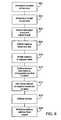
- FIG. 9is a diagram illustrating a method of making delivering an extendeble stent of the present invention to a treatment site.
- FIG. 10illustrates a cross-sectional view of a delivery system for an extendable stent of the present invention.
- FIG. 11illustrates a cross-sectional view of the delivery system of FIG. 10 with a stent superimposed on the delivery system.
- FIGS. 1 and 2illustrate a plan view of a bifurcated stent 100, which has been cut and laid open for illustrative purposes.
- stent 100In its unaltered state, stent 100 is generally hollow and cylindrical in shape, as known to those of ordinary skill in the art.
- Stent 100includes a trunk 102, a first branch 104, and a second branch 106.
- Stent 100is a bifurcated stent such that trunk 102 is designed to fit into a main vessel and first and second branches 104 and 106 are designed to fit into branch vessels extending from the main vessel, sometimes referred to as a main branch and a side branch.
- Trunk 102includes rings 112 a -112 d .
- Each of rings 112 a -112 dextends around the cylindrical body of stent 100 and includes an undulating series of peaks 122 and valleys 120 connected together by segments 118. Although four (4) rings 112 a -112 d are shown in FIGS. 1 and 2 , it would be understood one of ordinary skill in the art that any desirable amount of rings may be used, depending on the nature and location of the stenosis.
- first branch 102comprises rings 116 a- 116e and second branch 104 comprises rings 114 a -114 e , each including an undulating series of peaks 122 and valleys 120 connected together by segments 118.
- Rings 112 a -112 dare coupled together at weld points 124 connecting a peak of one ring to a valley of an adjacent ring.
- every other peak of one ringis connected to the corresponding valley of the adjacent ring.
- ring 112 ais coupled to ring 112 b at four (4) weld points 124.
- weld points 124are shown in FIGS. 1 and 2 to connect rings 112 a -112 d together, one of ordinary skill in the art would understand that other ways of coupling the rings may be used, for example, links may be used. Links may connect peak to valley, peak to peak, or may connect from a segment to an adjacent segment or to a peak or valley.
- FIGS. 1 and 2shows that the undulations of rings 112 a -112 d are "out of phase" by 180 degrees with adjacent rings, such that a peak of one ring matches up with a valley of an adjacent ring, the rings may be "in phase” such that peaks align with peaks and valleys align with valleys, or the rings may be out of phase by an amount less than 180 degrees.
- First branch 104 and second branch' 106are coupled to trunk 102 at weld points 126 and 128, respectively.
- other ways of connecting branches 104 and 106 to trunk 102may be used, such as links.
- one (1) weld pointis shown for each branch to trunk connection, it would be understood that more than one connection can be used.
- First branch 104includes a longitudinally extendable portion 108.
- longitudinally extendable portion 108includes rings 116 a , 116 b , and 116 c .
- Ring 116 ais coupled to ring 116 b and ring 116 b is coupled to ring 116 c by links 130.
- links 130include curved portions 132.
- second branch 106includes a longitudinally extendable portion 110.
- longitudinally extendable portion 110includes rings 114 a , 114 b , and 114 c .
- Ring 114 ais coupled to ring 114 b and ring 114 b is coupled to ring 114 c by links 130.
- extendable portions 108 and 110may include more or less rings, although at least two rings would generally be necessary to form an extendable portion.
- rings 116 c -116 e and rings 114 c -114 eare coupled to each other at weld points 124.
- stent 100can be used at branched vessels with stenoses of different lengths without having to use a different stent.
- a physiciancan view the stenosis and adjust the length of one or both branches 104, 106 by pulling on the branch.
- first branch 104has been pulled, thereby resulting in links 130 straightening and rings 116 a -116 c of longitudinally extendable portion 108 separating from each other.
- first branch 104has effectively become longer and covers a longer stenosis. Because rings 116 a -116 c have been separated, coverage of the stenosis in the areas between the rings is reduced.
- FIGS. 3 and 4illustrate a plan view of a bifurcated stent 200, which has been cut and laid open for illustrative purposes. Similar to stent 100 of FIGS. 1 and 2 , stent 200 includes a trunk 202, a first branch 204, and a second branch 206. Stent 200 is a bifurcated stent such that trunk 202 is designed to fit into a main vessel and first and second branches 204 and 206 are designed to fit into branch vessels extending from the main vessel, sometimes referred to as a main branch and a side branch.
- Trunk 202includes rings 212 a- 212 d .
- Each of rings 212 a -212 dextends around the cylindrical body of stent 200 and includes an undulating series of peaks 222 and valleys 220 connected together by segments 218.
- four (4) rings 212 a -212 dare shown in FIGS. 3 and 4 , it would be understood one of ordinary skill in the art that any desirable amount of rings may be used, depending on the nature and location of the stenosis.
- first branch 202comprises rings 216 a -216 g and second branch 204 comprises rings 214 a -214 g , each including an undulating series of peaks and valleys connected together by segments.
- Rings 212 a -212 dare coupled together at weld points 224 connecting a peak of one ring to a valley of an adjacent ring.
- every other peak of one ringis connected to the corresponding valley of the adjacent ring.
- ring 212 ais coupled to ring 212 b at four (4) weld points 224.
- weld points 224are shown in FIGS. 3 and 4 connecting rings 212 a -212 d together, one of ordinary skill in the art would understand that other ways of coupling the rings may be used, for example, links may be used. Links may connect peak to valley, peak to peak, or may connected from a segment to an adjacent segment or to a peak or valley.
- FIGS. 3 and 4shows that the undulations of rings 212 a -212 d are "out of phase" by 180 degrees with adjacent rings, such that a peak of one ring matches up a valley of an adjacent ring, the rings may be "in phase” such that peaks align with peaks and valleys align with valleys, or the rings may be out of phase by an amount less than 180 degrees.
- First branch 204 and second branch 206are coupled to trunk 202 by connecting links 226 and 228, respectively.
- links 226 and 228, respectivelymay be used, such as welds shown in FIGS 1 and 2 .
- FIGS 1 and 2may be used, while one (1) link is shown for each branch to trunk connection, it would be understood that more than one link can be used for each connection.
- First branch 204includes a longitudinally extendable portion 208.
- longitudinally extendable portion 108includes rings 216 a , 216 b , 216 c , and 216 d .
- Ring 216 ais coupled to ring 216 b
- ring 216 bis coupled to ring 216 c
- ring 216 cis coupled to ring 216 d by links 230.
- links 230include curved portions 232.
- second branch 206includes a longitudinally extendable portion 210.
- Longitudinally extendable portion 210includes rings 214 a , 214 b , 214 c , and 214 d .
- Ring 214 ais coupled to ring 214 b
- ring 214 bis coupled to ring 214 c
- ring 214 cis coupled to ring 214 d by links 230.
- Extendable portions 208 and 210are similar to extendable portions 108 and 110 of FIGS. 1 and 2 , except that rings 216 a -216 d and 214 a -214 d of extendable portions 208 and 210 are denser than the remaining rings 216 e -216 g and 214 e -214 g of first and second branches 204 and 206. In other words, as shown in FIGS.
- rings 216 a -216 d and 214 a -214 dinclude peaks 244, valleys 240, and segments 242 connecting the peaks 244 and valleys 240, similar to peaks 222, valleys 220, and segments 218. However, segments 242 are shorter longitudinally than segments 218. Further, the radius of the bends of peaks 244 and valleys 240 is smaller than the radius of the bends of peaks 222 and valleys 220. Accordingly, a quantity of rings 216 a -216 d and 214 a -214 d is shorter longitudinally than the same quantity of rings 216 e -216 g and 214 e -214 g .
- each ring 216 e -216 gincludes a total of nine (9) peaks and valleys, whereas each rig 216 a -216 d includes 16 peaks and valleys.
- extendable portions 208 and 210may include more or less rings, although at least two rings would generally be necessary to form an extendable portion.
- rings 216 e -216 g and rings 214 e -214 gare coupled to each other at weld points 224.
- stent 200 of the embodiment of FIGS. 3 and 4can be used at branched vessels with stenoses of different lengths without having to use a different stent.
- a physiciancan view the stenosis and adjust the length of one or both branches 204, 206 by pulling on the branch.
- first branch 204has been pulled, thereby resulting in links 230 straightening and rings 116 a- 116 d of longitudinally extendable portion 108 separating from each other.
- first branch 204has effectively become longer and covers a longer stenosis. Because rings 216 a -216 d are denser than rings 216 e -216 g coverage of the stenosis in the area of extendable portion 208 is not compromised despite rings 216a-216d being pulled away from each other.
- the ringsare welded to each other.
- a typical method of making a stenta thin-walled, small diameter metallic tube is cut to produce the desired stent pattern, using methods such as laser cutting or chemical etching. The cut stent may then be descaled, polished, cleaned and rinsed. The trunk and each branch of the stents described could be made using this method, and then coupled by a weld or link, as shown. Using, such a method, instead of a weld between rings, a link is normally cut out of the tube, as shown in FIG. 5 .
- FIG. 5a peak 322, valley 320, and segment 318 connecting the peak and valley of portions of adjacent rings 312 are shown.
- a link 324couples a peak 322 of one ring 312 to a valley 320 of an adjacent ring 312.
- FIG. 6shows a curved connecting link 330 used to connect a segment 318 of one ring to a segment 318 of an adjacent ring.
- Such a linkcan be used for longitudinally extendable portions 108, 110, 208, 210 described in FIGS. 1-4 or for connecting any other adjacent rings in stents 100, 200.
- FIGS. 7 and 8show an embodiment of a spirally wound wire bifurcated stent 400.
- Stent 400includes a trunk 402, a first branch 404, and a second branch 406.
- First branch 404is coupled to trunk 402 at weld 426 and second branch 406 is coupled to trunk 402 at weld 428.
- Trunk 402is formed by a wire 446 formed in a zig-zag shape and then wrapped around a mandrel, as described, for example, in U.S. Patent No. 5,133,732 to Wiktor .
- a free end 440 of wire 446may be wrapped around a portion of wire 446 so that free end 440 expands with the remainder of trunk 402.
- free end 440may be welded to wire 446, as would be understood by one of ordinary skill in the art.
- First and second branches 404 and 406are similarly formed by wires 448 and 450, respectively, formed in a zig-zag shaped and wrapped around a mandrel.
- Free ends 442 and 444 of wires 448 and 450are wrapped around a portion of wires 448 and 450, respectively.
- free ends 442 and 44may alternatively be welded.
- First branch 404 of stent 400includes a longitudinally extendable portion 408.
- Longitudinally extendable portion 408is formed by wrapping wire 448 around a mandrel at a tighter pitch than the remainder of first branch 404, as can be seen in FIG. 2 .
- second branch 406may include a longitudinally extendable portion 410 formed by wrapping wire 450 around a mandrel at a tighter pitch than the remainder of second branch 406.
- a physicianmay pull one of the branches to extend the length thereof. For example, as shown in FIG.
- first branch 404may be pulled such that extendable section 408 extends from the tighter pitch of FIG. 7 to the wider pitch of FIG. 8 , thereby extending the effective length of first branch 404.
- second branch 406may also be extended, or only second branch 406 may be extended and first branch 404 may remain at the length shown in FIG. 7 .
- the term "pitch” as used hereinis used as the term is used in relation to coil springs, that is, the distance from center to center of the wire in adjacent coils.
- a "tighter pitch”has a smaller distance from center to center of the wire in adjacent coils and a “wider pitch” has a larger distance from center to center of the wire in adjacent coils.
- the material for the stent of any of the above embodimentsmay be any material that is typically used for a stent, for example, stainless steel, "MP35N,” “MP20N,” nickel titanium alloys such as Nitinol, tantalum, platinum-iridium alloy, gold, magnesium, L605, or combinations thereof.
- MP35N and MP20Nare trade names for alloys of cobalt, nickel, chromium and molybdenum available from standard Press Steel Co., Jenkintown, Pa.
- “MP35N”consists of 35% cobalt, 35% nickel, 20% chromium, and 10% molybdenum.
- MP20Nconsists of 50% cobalt, 20% nickel, 20% chromium, and 10% molybdenum.
- the stents of the embodiments describedmay be coated, for example, with a polymer coating.
- bioabsorbable, biodegradable materialsinclude but are not limited to polycaprolactone (PCL), poly-D, L-lactic acid (DL-PLA), poly-L-lactic acid (L-PLA), poly(lactide-co-glycolide), poly(hydroxybutyrate), poly(hydroxybutyrate-co-valerate), polydioxanone, polyorthoester, polyanhydride, poly(glycolic acid), poly(glycolic acid-cotrimethylene carbonate), polyphosphoester, polyphosphoester urethane, poly (amino acids), cyanoacrylates, poly(trimethylene carbonate), poly(iminocarbonate), copoly(ether-esters), polyalkylene oxalates, polyphosphazenes, polyiminocarbonates, and aliphatic polycarbonates.
- Biomoleculessuch as heparin, fibrin, fibrinogen, cellulose, starch, and collagen are typically also suitable.
- biostable polymersinclude Parylene®, Parylast®, polyurethane (for example, segmented polyurethanes such as Biospan®), polyethylene, polyethlyene terephthalate, ethylene vinyl acetate, silicone and polyethylene oxide.
- the stents described abovemay include a therapeutic substance either directly applied to the stent, in reservoirs in the stent, or as part of a polymer coating, or other ways that would be recognized by one of ordinary skill in the art.
- Therapeutic substancescan include, but are not limited to, antineoplastic, antimitotic, antiinflammatory, antiplatelet, anticoagulant, anti fibrin, antithrombin, antiproliferative, antibiotic, antioxidant, and antiallergic substances as well as combinations thereof.
- antineoplastics and/or antimitoticsinclude paclitaxel (e.g., TAXOL® by Bristol-Myers Squibb Co., Stamford, Conn.), docetaxel (e.g., Taxotere® from Aventis S.
- methotrexatemethotrexate
- azathioprineazathioprine
- vincristinevinblastine
- fluorouracildoxorubicin hydrochloride
- doxorubicin hydrochloridee.g., Adriamycin® from Pharmacia & Upjohn, Peapack N.J.
- mitomycine.g., Mutamycin® from Bristol-Myers Squibb Co., Stamford, Conn.
- antiplateletsexamples include sodium heparin, low molecular weight heparins, heparinoids, hirudin, argatroban, forskolin, vapiprost, prostacyclin and prostacyclin analogues, dextran, D-phe-pro-arg-chloromethylketone (synthetic antithrombin), dipyridamole, glycoprotein IIb/IIIa platelet membrane receptor antagonist antibody, recombinant hirudin, and thrombin inhibitors such as AngiomaxTM (Biogen, Inc., Cambridge, Mass.).
- AngiomaxTMBiogen, Inc., Cambridge, Mass.
- cytostatic or antiproliferative agentsinclude angiopeptin, angiotensin converting enzyme inhibitors such as captopril (e.g., Capoten® and Capozide® from Bristol-Myers Squibb Co., Stamford, Conn.), cilazapril or lisinopril (e.g., Prinivil® and Prinzide® from Merck & Co., Inc., Whitehouse Station, N.J.), calcium channel blockers (such as nifedipine), colchicine, fibroblast growth factor (FGF) antagonists, fish oil (omega 3-fatty acid), histamine antagonists, lovastatin (an inhibitor of HMG-CoA reductase, a cholesterol lowering drug, brand name Mevacor® from Merck & Co., Inc., Whitehouse Station, N.J.), monoclonal antibodies (such as those specific for Platelet-Derived Growth Factor (PDGF) receptors), nitroprusside, phosphoric acid
- an antiallergic agentis permirolast potassium.
- Other therapeutic substances or agents that may be usedinclude alpha-interferon, genetically engineered epithelial cells, and dexamethasone.
- the therapeutic substanceis a radioactive isotope for implantable device usage in radiotherapeutic procedures.
- radioactive isotopesinclude, but are not limited to, phosphorus (P 32 ), palladium (Pd 103 ), cesium (Cs 131 ), Iridium (I 192 ) and iodine (I 125 ). While the preventative and treatment properties of the foregoing therapeutic substances or agents are well-known to those of ordinary skill in the art, the substances or agents are provided by way of example and are not meant to be limiting. Other therapeutic substances are equally applicable for use with the disclosed methods and compositions.
- the present inventionalso relates to a method of delivering a bifurcated stent to a stenosed region of a branched vessel.
- step 902 of the methodis a step of determining the location of the stenosis.
- Step 902is generally performed angiographically.
- Step 904includes assessing the length of the stenosis in the main vessel and the branch vessels, which is also generally done angiographically.
- step 906includes selecting a bifurcated stent according to the present invention and adjusting the length of one or both of the branches by pulling the stent proximally on the delivery catheter.
- Step 908includes delivering the stent and catheter to the site of the stenosis.
- Step 910includes inflating the balloon of the balloon catheter to expand the bifurcated stent. Because the stent was extended, the balloon does not expand the entire stent. Therefore, step 912 includes deflating the balloon and moving it to the unexpanded portion of the stent.
- Step 914includes re-inflating the balloon to expand the remainder of the stent.
- Step 916includes deflating the balloon and step 918 includes withdrawing the balloon catheter from the vessel.
- a delivery catheter 510in another embodiment for delivering a bifurcated stent 500 of the present invention, shown in FIGS. 10 and 11 , shown in FIGS. 10 and 11 , a delivery catheter 510 includes a balloon 512 mounted on a catheter 514.
- Catheter 514is a Y-shaped catheter for delivering a bifurcated stent. Accordingly, catheter 514 includes a trunk portion 516, a first branch 518, and a second branch 520.
- Catheter 514includes a proximal outer shaft 522, a first branch outer shaft 524, and a second branch outer shaft 526.
- Catheter 514further includes a first inner shaft 528 extending at least partially through proximal outer shaft 522 and through first branch outer shaft 524.
- Catheter 514also includes a second inner shaft 530 extending at least partially through proximal outer shaft 522 and through second branch outer shaft 526.
- catheter 514could also be a rapid exchange catheter, without departing from the scope of the present invention.
- a first balloon 536is mounted on first branch 518 and a second balloon 538 is mounted on second branch 520.
- a proximal neck 544 of first balloon 536is bonded to a distal portion of first branch outer shaft 524 and a distal neck 546 of first balloon 536 is bonded to a distal portion of first inner shaft 528.
- a proximal neck 548 of second balloon 536is bonded to a distal portion of second branch outer shaft 526 and a distal neck 550 of second balloon 538 is bonded to a distal portion of second inner shaft 530.
- First balloon 536includes a longitudinally extendable portion 540 and second balloon 538 includes a longitudinally extendable portion 542.
- first and second balloons 536 and 538permit first and second balloons 536 and 538 to extend longitudinally with the longitudinally extendable portions of the stents of the present invention, as described above.
- first and second balloons 536 and 538include bellows type folds to created longitudinally extendable portions 540 and 542, respectively.
- First inner shaft 528 and second inner shaft 530extend in conjunction with first and second balloons 536 and 538, respectively.
- FIG. 11shows an exemplary bifurcated stent 560 mounted on the delivery system 500 of the present invention.
- a trunk portion 562 of stent 560is mounted over first and second balloons 536 and 538.
- a first branch 564 of stent 560is mounted over only first balloon 536 and a second branch 566 of stent 560 is mounted on second balloon 538.
- Such an arrangementis similar to that described in U.S. Patent No. 6,129,738 to Lashinsky et al.
- the location and size of the stenosisare determined, for example, by angiograph.
- stent 560 mounted on delivery system 500With stent 560 mounted on delivery system 500, stent 560, first and/or second balloons 536 and 538, and first and/or second inner shafts 528 and 530 are extended an appropriate amount to cover the stenosis. Stent 560 is then delivered to the treatment site mounted on delivery system 500. When stent 560 has reached the delivery site, first and second balloons 536 and 538 are inflated to expand stent 560. After stent 560 is in place in its expanded state, first and second balloons 536 and 538 are deflated and delivery system 500 is removed from the vessel, leaving stent 560 in place.
Landscapes
- Health & Medical Sciences (AREA)
- Engineering & Computer Science (AREA)
- Biomedical Technology (AREA)
- Heart & Thoracic Surgery (AREA)
- Life Sciences & Earth Sciences (AREA)
- Cardiology (AREA)
- Oral & Maxillofacial Surgery (AREA)
- Transplantation (AREA)
- Veterinary Medicine (AREA)
- Vascular Medicine (AREA)
- Public Health (AREA)
- Animal Behavior & Ethology (AREA)
- General Health & Medical Sciences (AREA)
- Optics & Photonics (AREA)
- Physics & Mathematics (AREA)
- Media Introduction/Drainage Providing Device (AREA)
- Prostheses (AREA)
- Materials For Medical Uses (AREA)
Abstract
Description
- The present invention relates generally to bifurcated stents. More particularly, the present invention is directed to a bifurcated stent wherein the length of the branches of the stent can be adjusted prior to implantation.
- A number of medical procedures involve or can be supplemented with the placement of an endoluminal prosthesis, commonly referred to as a stent, that can be implanted in a lumen, such as a blood vessel or other natural pathway of a patient's body. Such stents typically define a generally tubular configuration, and are expandable from a relatively small diameter (low profile) to an enlarged diameter. While in its low profile configuration, the stent is advanced endoluminally, by a delivery device, through the body lumen to the site where the stent is to be placed. The stent then can be expanded to a larger diameter in which it can firmly engage the inner wall of the body lumen. The delivery device then is removed, leaving the implanted stent in place. In that manner, the stent may serve to maintain open a blood vessel or other natural duct, the functioning of which had become impaired as a result of a pathological or traumatic occurrence.
- Among the medical procedures in which stents have had increasing use is in connection with percutaneous transluminal angioplasty (PTA), and particularly percutaneous transluminal coronary angioplasty (PTCA). PTA and PTCA involve the insertion and manipulation of a dilating catheter through the patient's arteries to place the dilatation balloon of the catheter within an obstructed portion (stenosis) of a blood vessel. The balloon then is expanded forcibly within the obstruction to dilate that portion of the blood vessel thereby to restore blood flow through the blood vessel. Among the more significant complications that may result from such angioplasty is that in a significant number of cases, the dilated site again becomes obstructed. By placing a stent within the blood vessel at the treated site, the tendency for such restenosis may be reduced.
- Stenoses often may develop in the branching region of a patient's blood vessel. Treatment of a stenosis in the branched region may present numerous additional difficulties in the design of devices to dilate stenoses at the branched region. Techniques and devices have been developed to effect a dilatation at a branched region such as the "kissing balloon" technique described in
U.S. Pat. No. 4,896,670 . - A number of stents have been proposed and developed in the art, including single stents that define a single luminal pathway as well as bifurcated stents that define a branched pathway and are intended to be placed in a branching region of a blood vessel. The development of bifurcated stents, as compared to single stents presents numerous difficulties because of the branched arrangement and the difficulty in delivering and placing a bifurcated stent at the branched region of a blood vessel.
U.S. Pat. No. 4,994,071 (MacGregor ) discloses a design for a bifurcating stent intended to be inserted into a bifurcated blood vessel. The stent is constructed from two lengths of continuous wire, one of which is formed in a series of interconnected loops to define a common tubular branch and one of the bifurcated branches. The other length of wire also is formed in a series of similarly interconnected loops to define the other branch of the bifurcation. The two assemblies of interconnected loops are connected together to define a Y-shaped structure. The interconnection between the structure defining the bifurcated branches is said to enable them to be bent to conform to the shape of the vessels into which the device is intended to be inserted. The loops are formed so that they can be expanded from an initial diameter to facilitate insertion into the blood vessel to an expanded, deployed diameter.US 7112217 teaches a bifurcated stent-graft system including a telescopic mechanism to permit in-situ length adjustment.- The MacGregor and other bifurcated devices present a number of difficulties. Its continuous wire construction does not readily lend itself to precise matching to the vascular anatomy of pathological situation of the specific patient in whom the stent is to be placed. The construction is adapted, as a practical matter, only to be manufactured in standard configurations and lengths. When a standard length of stent does not ideally match the patient's anatomy, the physician would be forced to choose among the available standard lengths and configurations in an effort to make a selection that, at best, could be considered to be a compromise.
- A bifurcated stent is disclosed including a trunk portion and first and second branches. At least one of the branches includes a longitudinally extendable portion such that the branch can be extended from a first length up to second length. In one embodiment, the trunk portion includes a plurality of cylindrical rings coupled to each other, and each of the first and second branches includes a plurality of cylindrical rings coupled to each other. The cylindrical rings of the longitudinally extendable portion are coupled to each other by a link with a curved portion. Upon pulling of the branch, the link with the curved portion straightens, thereby lengthening the branch.
- In another embodiment, the trunk portion is formed from a continuous wire formed into a zig-zag pattern and spirally wound around a mandrel to form a cylindrical body. The first branch is also formed from a continuous wire formed into a zig-zag pattern and spirally wound around a mandrel to form a cylindrical body. The second branch is also formed from a continuous wire formed into a zig-zag pattern and spirally wound around a mandrel to form a cylindrical body. At least one of the first and second branches includes a longitudinally extendable portion. The longitudinally extendable portion is formed by winding the continuous wire of the branch at a first pitch whereas the remainder of the branch is wound at a second pitch greater than the first pitch. Thus, when the branch with the longitudinally extendable portion is pulled, the pitch of the longitudinally extendable portion increases, thereby lengthening the branch.
- A method of treating a stenosis at a branched vessel of a patient is also disclosed. The method includes determining the location and the size of the stenosis. Stents are normally provided already mounted on the delivery system. In an embodiment, the delivery system is a balloon catheter. After determining the size of the stenosis, a stent and delivery system combination is selected. Based on the size of the stenosis, one or both of the branches may be longitudinally extended to fit the length of the stenosis in the particular branch of the vessel. The stent and delivery system are inserted into the vessel and advanced to the site of the stenosis. The balloon(s) of the balloon catheter is inflated to expand at least a portion of the stent. However, because at least a portion of the stent was lengthened, the balloon may not expand the entire stent. Therefore, the balloon is deflated, relocated to the unexpanded portion of the stent, and re-inflated to expand the unexpanded portion of the stent. The balloon(s) is then deflated and the delivery system is withdrawn from the vessel. In an alternative embodiment, the balloon(s) of the balloon catheter is also provided with a longitudinally extendable portion such that when the stent is lengthened, the balloon(s) is also lengthened. Such an embodiment eliminates the steps of deflating, relocating, and re-inflating the balloon(s).
- The foregoing and other features and advantages of the invention will be apparent from the following description of the invention as illustrated in the accompanying drawings. The accompanying drawings, which are incorporated herein and form a part of the specification, further serve to explain the principles of the invention and to enable a person skilled in the pertinent art to make and use the invention. The drawings are not to scale.
FIG. 1 illustrates a plan view of a bifurcated stent which has been cut and laid open.FIG. 2 illustrates a plan view of the stent ofFIG. 1 with one of the branches extended.FIG. 3 illustrates a plan view of another embodiment of a bifurcated stent which has been cut and laid open.FIG. 4 illustrates a plan view of the stent ofFIG. 3 with one of the branches extended.FIG. 5 illustrates a plan view of a portion of a stent.FIG. 6 illustrates a plane view of a portion of a stent.FIG. 7 illustrates a perspective view of a stent of another embodiment of the present invention.FIG. 8 illustrates a perspective view of the stent ofFIG. 7 with one of the branches extended.FIG. 9 is a diagram illustrating a method of making delivering an extendeble stent of the present invention to a treatment site.FIG. 10 illustrates a cross-sectional view of a delivery system for an extendable stent of the present invention.FIG. 11 illustrates a cross-sectional view of the delivery system ofFIG. 10 with a stent superimposed on the delivery system.- Specific embodiments of the present invention are now described with reference to the figures, where like reference numbers indicate identical or functionally similar elements. While specific embodiments are discussed in detail, it should be understood that this is done for illustrative purposes only. A person skilled in the art will recognize that other embodiments can be used without departing from the scope of the invention.
FIGS. 1 and 2 illustrate a plan view of abifurcated stent 100, which has been cut and laid open for illustrative purposes. In its unaltered state,stent 100 is generally hollow and cylindrical in shape, as known to those of ordinary skill in the art.Stent 100 includes atrunk 102, afirst branch 104, and asecond branch 106.Stent 100 is a bifurcated stent such thattrunk 102 is designed to fit into a main vessel and first andsecond branches Trunk 102 includesrings 112a-112d. Each ofrings 112a-112d extends around the cylindrical body ofstent 100 and includes an undulating series ofpeaks 122 andvalleys 120 connected together bysegments 118. Although four (4) rings 112a-112d are shown inFIGS. 1 and 2 , it would be understood one of ordinary skill in the art that any desirable amount of rings may be used, depending on the nature and location of the stenosis. Similarly,first branch 102 comprisesrings 116a-116e andsecond branch 104 comprisesrings 114a-114e, each including an undulating series ofpeaks 122 andvalleys 120 connected together bysegments 118.Rings 112a-112d are coupled together at weld points 124 connecting a peak of one ring to a valley of an adjacent ring. In the embodiment shown inFIGS. 1 and 2 , every other peak of one ring is connected to the corresponding valley of the adjacent ring. For example,ring 112a is coupled toring 112b at four (4) weld points 124. While weld points 124 are shown inFIGS. 1 and 2 to connectrings 112a-112d together, one of ordinary skill in the art would understand that other ways of coupling the rings may be used, for example, links may be used. Links may connect peak to valley, peak to peak, or may connect from a segment to an adjacent segment or to a peak or valley. Similarly, while the embodiment ofFIGS. 1 and 2 shows that the undulations ofrings 112a-112d are "out of phase" by 180 degrees with adjacent rings, such that a peak of one ring matches up with a valley of an adjacent ring, the rings may be "in phase" such that peaks align with peaks and valleys align with valleys, or the rings may be out of phase by an amount less than 180 degrees.First branch 104 and second branch' 106 are coupled totrunk 102 at weld points 126 and 128, respectively. As would be understood by one of ordinary skill in the art, other ways of connectingbranches trunk 102 may be used, such as links. Further, while one (1) weld point is shown for each branch to trunk connection, it would be understood that more than one connection can be used.First branch 104 includes a longitudinallyextendable portion 108. In the embodiment ofFIGS. 1 and 2 , longitudinallyextendable portion 108 includesrings Ring 116a is coupled toring 116b andring 116b is coupled to ring 116c bylinks 130. In the embodiment shown inFIGS. 1 and 2 ,links 130 includecurved portions 132. Similarly,second branch 106 includes a longitudinallyextendable portion 110. In the embodiment ofFIGS. 1 and 2 , longitudinallyextendable portion 110 includesrings Ring 114a is coupled toring 114b andring 114b is coupled to ring 114c bylinks 130. As would be understood by one of ordinary skill in the art,extendable portions FIGS. 1 and 2 , rings 116c-116e and rings 114c-114e are coupled to each other at weld points 124.- In practice,
stent 100 can be used at branched vessels with stenoses of different lengths without having to use a different stent. A physician can view the stenosis and adjust the length of one or bothbranches FIG. 2 ,first branch 104 has been pulled, thereby resulting inlinks 130 straightening andrings 116a-116c of longitudinallyextendable portion 108 separating from each other. Thus,first branch 104 has effectively become longer and covers a longer stenosis. Becauserings 116a-116c have been separated, coverage of the stenosis in the areas between the rings is reduced. However, in the embodiment shown, only twolinks 130 have been provided betweenrings links 130 betweenrings more links 130 can be provided between the rings. - Another way to increase coverage in the longitudinally extendable portions of the branches of a bifurcated stent is shown in another embodiment of the present invention shown in
FIGS. 3 and 4. FIGS. 3 and 4 illustrate a plan view of abifurcated stent 200, which has been cut and laid open for illustrative purposes. Similar tostent 100 ofFIGS. 1 and 2 ,stent 200 includes atrunk 202, afirst branch 204, and asecond branch 206.Stent 200 is a bifurcated stent such thattrunk 202 is designed to fit into a main vessel and first andsecond branches Trunk 202 includesrings 212a-212d. Each ofrings 212a-212d extends around the cylindrical body ofstent 200 and includes an undulating series ofpeaks 222 andvalleys 220 connected together bysegments 218. Although four (4) rings 212a-212d are shown inFIGS. 3 and 4 , it would be understood one of ordinary skill in the art that any desirable amount of rings may be used, depending on the nature and location of the stenosis. Similarly,first branch 202 comprisesrings 216a-216g andsecond branch 204 comprisesrings 214a-214g, each including an undulating series of peaks and valleys connected together by segments. Rings 212a-212d are coupled together at weld points 224 connecting a peak of one ring to a valley of an adjacent ring. In the embodiment shown inFIGS. 3 and 4 , every other peak of one ring is connected to the corresponding valley of the adjacent ring. For example,ring 212a is coupled toring 212b at four (4) weld points 224. While weld points 224 are shown inFIGS. 3 and 4 connectingrings 212a-212d together, one of ordinary skill in the art would understand that other ways of coupling the rings may be used, for example, links may be used. Links may connect peak to valley, peak to peak, or may connected from a segment to an adjacent segment or to a peak or valley. Similarly, while the embodiment ofFIGS. 3 and 4 shows that the undulations ofrings 212a-212d are "out of phase" by 180 degrees with adjacent rings, such that a peak of one ring matches up a valley of an adjacent ring, the rings may be "in phase" such that peaks align with peaks and valleys align with valleys, or the rings may be out of phase by an amount less than 180 degrees.First branch 204 andsecond branch 206 are coupled totrunk 202 by connectinglinks branches trunk 202 may be used, such as welds shown inFIGS 1 and 2 . Further, while one (1) link is shown for each branch to trunk connection, it would be understood that more than one link can be used for each connection.First branch 204 includes a longitudinallyextendable portion 208. In the embodiment ofFIGS. 3 and 4 , longitudinallyextendable portion 108 includesrings Ring 216a is coupled toring 216b,ring 216b is coupled toring 216c, andring 216c is coupled to ring 216d bylinks 230. In the embodiment shown inFIGS. 3 and 4 links 230 includecurved portions 232. Similarly,second branch 206 includes a longitudinallyextendable portion 210. Longitudinallyextendable portion 210 includesrings Ring 214a is coupled toring 214b,ring 214b is coupled toring 214c, andring 214c is coupled to ring 214d bylinks 230.Extendable portions extendable portions FIGS. 1 and 2 , except that rings 216a-216d and 214a-214d ofextendable portions rings 216e-216g and 214e-214g of first andsecond branches FIGS. 3 and 4 rings 216a-216d and 214a-214d includepeaks 244,valleys 240, andsegments 242 connecting thepeaks 244 andvalleys 240, similar topeaks 222,valleys 220, andsegments 218. However,segments 242 are shorter longitudinally thansegments 218. Further, the radius of the bends ofpeaks 244 andvalleys 240 is smaller than the radius of the bends ofpeaks 222 andvalleys 220. Accordingly, a quantity ofrings 216a-216d and 214a-214d is shorter longitudinally than the same quantity ofrings 216e-216g and 214e-214g. Further,more peaks 244 andvalleys 240 are required to create a cylindrical body of the same diameter as a cylindrical body created bypeaks 222 andvalleys 220. For example, in the embodiment ofFIGS. 3 and 4 , eachring 216e-216g includes a total of nine (9) peaks and valleys, whereas eachrig 216a-216d includes 16 peaks and valleys. As would be understood by one of ordinary skill in the art,extendable portions FIGS. 3 and 4 , rings 216e-216g andrings 214e-214g are coupled to each other at weld points 224.- Similar to
FIGS. 1 and 2 ,stent 200 of the embodiment ofFIGS. 3 and 4 can be used at branched vessels with stenoses of different lengths without having to use a different stent. A physician can view the stenosis and adjust the length of one or bothbranches FIG. 4 ,first branch 204 has been pulled, thereby resulting inlinks 230 straightening andrings 116a-116d of longitudinallyextendable portion 108 separating from each other. Thus,first branch 204 has effectively become longer and covers a longer stenosis. Becauserings 216a-216d are denser thanrings 216e-216g coverage of the stenosis in the area ofextendable portion 208 is not compromised despiterings 216a-216d being pulled away from each other. - In the embodiments shown in
FIGS. 1-4 , the rings are welded to each other. However, one of ordinary skill would recognize that there are several ways to make the stents described inFIGS. 1-4 . For example, in a typical method of making a stent, a thin-walled, small diameter metallic tube is cut to produce the desired stent pattern, using methods such as laser cutting or chemical etching. The cut stent may then be descaled, polished, cleaned and rinsed. The trunk and each branch of the stents described could be made using this method, and then coupled by a weld or link, as shown. Using, such a method, instead of a weld between rings, a link is normally cut out of the tube, as shown inFIG. 5 . InFIG. 5 , apeak 322,valley 320, andsegment 318 connecting the peak and valley of portions ofadjacent rings 312 are shown. Alink 324 couples apeak 322 of onering 312 to avalley 320 of anadjacent ring 312.FIG. 6 shows a curved connectinglink 330 used to connect asegment 318 of one ring to asegment 318 of an adjacent ring. Such a link can be used for longitudinallyextendable portions FIGS. 1-4 or for connecting any other adjacent rings instents - Some examples of other methods of forming stents and structures for stents are shown in
U.S. Patent No. 4,733,665 to Palmaz ,U.S. Patent No. 4,800,882 to Gianturco ,U.S. Patent No. 4,886,062 to Wiktor ,U.S. Patent No. 5,133,732 to Wiktor ,U.S. Patent No. 5,292,331 to Boneau ,U.S. Patent No. 5,421,955 to Lau,U.S. Patent No. 5,935,162 to Dang ,U.S. Patent No. 6,090,127 to Globerman , andU.S. Patent No. 6,730,116 to Wolinsky et al. FIGS. 7 and 8 show an embodiment of a spirally wound wire bifurcatedstent 400.Stent 400 includes atrunk 402, afirst branch 404, and asecond branch 406.First branch 404 is coupled totrunk 402 atweld 426 andsecond branch 406 is coupled totrunk 402 atweld 428.Trunk 402 is formed by awire 446 formed in a zig-zag shape and then wrapped around a mandrel, as described, for example, inU.S. Patent No. 5,133,732 to Wiktor . Afree end 440 ofwire 446 may be wrapped around a portion ofwire 446 so thatfree end 440 expands with the remainder oftrunk 402. In the alternative,free end 440 may be welded towire 446, as would be understood by one of ordinary skill in the art. First andsecond branches wires wires wires free end 440, free ends 442 and 44 may alternatively be welded.First branch 404 ofstent 400 includes a longitudinallyextendable portion 408. Longitudinallyextendable portion 408 is formed by wrappingwire 448 around a mandrel at a tighter pitch than the remainder offirst branch 404, as can be seen inFIG. 2 . Similarly,second branch 406 may include a longitudinallyextendable portion 410 formed by wrappingwire 450 around a mandrel at a tighter pitch than the remainder ofsecond branch 406. In practice, if a portion of stenosis in a branch of a branched vessel is longer than the length of first orsecond branch FIG. 8 ,first branch 404 may be pulled such thatextendable section 408 extends from the tighter pitch ofFIG. 7 to the wider pitch ofFIG. 8 , thereby extending the effective length offirst branch 404. As would be understood by one of ordinary skill in the art,second branch 406 may also be extended, or onlysecond branch 406 may be extended andfirst branch 404 may remain at the length shown inFIG. 7 . The term "pitch" as used herein is used as the term is used in relation to coil springs, that is, the distance from center to center of the wire in adjacent coils. Thus, as used herein, a "tighter pitch" has a smaller distance from center to center of the wire in adjacent coils and a "wider pitch" has a larger distance from center to center of the wire in adjacent coils.- The material for the stent of any of the above embodiments may be any material that is typically used for a stent, for example, stainless steel, "MP35N," "MP20N," nickel titanium alloys such as Nitinol, tantalum, platinum-iridium alloy, gold, magnesium, L605, or combinations thereof. "MP35N" and "MP20N" are trade names for alloys of cobalt, nickel, chromium and molybdenum available from standard Press Steel Co., Jenkintown, Pa. "MP35N" consists of 35% cobalt, 35% nickel, 20% chromium, and 10% molybdenum. "MP20N" consists of 50% cobalt, 20% nickel, 20% chromium, and 10% molybdenum.
- The stents of the embodiments described may be coated, for example, with a polymer coating. Examples of bioabsorbable, biodegradable materials include but are not limited to polycaprolactone (PCL), poly-D, L-lactic acid (DL-PLA), poly-L-lactic acid (L-PLA), poly(lactide-co-glycolide), poly(hydroxybutyrate), poly(hydroxybutyrate-co-valerate), polydioxanone, polyorthoester, polyanhydride, poly(glycolic acid), poly(glycolic acid-cotrimethylene carbonate), polyphosphoester, polyphosphoester urethane, poly (amino acids), cyanoacrylates, poly(trimethylene carbonate), poly(iminocarbonate), copoly(ether-esters), polyalkylene oxalates, polyphosphazenes, polyiminocarbonates, and aliphatic polycarbonates. Biomolecules such as heparin, fibrin, fibrinogen, cellulose, starch, and collagen are typically also suitable. Examples of biostable polymers include Parylene®, Parylast®, polyurethane (for example, segmented polyurethanes such as Biospan®), polyethylene, polyethlyene terephthalate, ethylene vinyl acetate, silicone and polyethylene oxide.
- The stents described above may include a therapeutic substance either directly applied to the stent, in reservoirs in the stent, or as part of a polymer coating, or other ways that would be recognized by one of ordinary skill in the art. Therapeutic substances can include, but are not limited to, antineoplastic, antimitotic, antiinflammatory, antiplatelet, anticoagulant, anti fibrin, antithrombin, antiproliferative, antibiotic, antioxidant, and antiallergic substances as well as combinations thereof. Examples of such antineoplastics and/or antimitotics include paclitaxel (e.g., TAXOL® by Bristol-Myers Squibb Co., Stamford, Conn.), docetaxel (e.g., Taxotere® from Aventis S. A., Frankfurt, Germany), methotrexate, azathioprine, vincristine, vinblastine, fluorouracil, doxorubicin hydrochloride (e.g., Adriamycin® from Pharmacia & Upjohn, Peapack N.J.), and mitomycin (e.g., Mutamycin® from Bristol-Myers Squibb Co., Stamford, Conn.). Examples of such antiplatelets, anticoagulants, antifibrin, and antithrombins include sodium heparin, low molecular weight heparins, heparinoids, hirudin, argatroban, forskolin, vapiprost, prostacyclin and prostacyclin analogues, dextran, D-phe-pro-arg-chloromethylketone (synthetic antithrombin), dipyridamole, glycoprotein IIb/IIIa platelet membrane receptor antagonist antibody, recombinant hirudin, and thrombin inhibitors such as Angiomax™ (Biogen, Inc., Cambridge, Mass.). Examples of such cytostatic or antiproliferative agents include angiopeptin, angiotensin converting enzyme inhibitors such as captopril (e.g., Capoten® and Capozide® from Bristol-Myers Squibb Co., Stamford, Conn.), cilazapril or lisinopril (e.g., Prinivil® and Prinzide® from Merck & Co., Inc., Whitehouse Station, N.J.), calcium channel blockers (such as nifedipine), colchicine, fibroblast growth factor (FGF) antagonists, fish oil (omega 3-fatty acid), histamine antagonists, lovastatin (an inhibitor of HMG-CoA reductase, a cholesterol lowering drug, brand name Mevacor® from Merck & Co., Inc., Whitehouse Station, N.J.), monoclonal antibodies (such as those specific for Platelet-Derived Growth Factor (PDGF) receptors), nitroprusside, phosphodiesterase inhibitors, prostaglandin inhibitors, suramin, serotonin blockers, steroids, thioprotease inhibitors, triazolopyrimidine (a PDGF antagonist), and nitric oxide. An example of an antiallergic agent is permirolast potassium. Other therapeutic substances or agents that may be used include alpha-interferon, genetically engineered epithelial cells, and dexamethasone. In other examples, the therapeutic substance is a radioactive isotope for implantable device usage in radiotherapeutic procedures. Examples of radioactive isotopes include, but are not limited to, phosphorus (P32), palladium (Pd103), cesium (Cs131), Iridium (I192) and iodine (I125). While the preventative and treatment properties of the foregoing therapeutic substances or agents are well-known to those of ordinary skill in the art, the substances or agents are provided by way of example and are not meant to be limiting. Other therapeutic substances are equally applicable for use with the disclosed methods and compositions.
- The present invention also relates to a method of delivering a bifurcated stent to a stenosed region of a branched vessel. As shown in
FIG. 9 , step 902 of the method is a step of determining the location of the stenosis. Step 902 is generally performed angiographically. Step 904 includes assessing the length of the stenosis in the main vessel and the branch vessels, which is also generally done angiographically. Once the location and size of the stenosis has been determined,step 906 includes selecting a bifurcated stent according to the present invention and adjusting the length of one or both of the branches by pulling the stent proximally on the delivery catheter. Step 908 includes delivering the stent and catheter to the site of the stenosis. Step 910 includes inflating the balloon of the balloon catheter to expand the bifurcated stent. Because the stent was extended, the balloon does not expand the entire stent. Therefore,step 912 includes deflating the balloon and moving it to the unexpanded portion of the stent. Step 914 includes re-inflating the balloon to expand the remainder of the stent. Step 916 includes deflating the balloon and step 918 includes withdrawing the balloon catheter from the vessel. - In another embodiment for delivering a
bifurcated stent 500 of the present invention, shown inFIGS. 10 and 11 , a delivery catheter 510 includes a balloon 512 mounted on acatheter 514.Catheter 514 is a Y-shaped catheter for delivering a bifurcated stent. Accordingly,catheter 514 includes atrunk portion 516, afirst branch 518, and asecond branch 520.Catheter 514 includes a proximalouter shaft 522, a first branchouter shaft 524, and a second branchouter shaft 526.Catheter 514 further includes a firstinner shaft 528 extending at least partially through proximalouter shaft 522 and through first branchouter shaft 524.Catheter 514 also includes a secondinner shaft 530 extending at least partially through proximalouter shaft 522 and through second branchouter shaft 526. As would be understood by one of ordinary skill in that art,catheter 514 could also be a rapid exchange catheter, without departing from the scope of the present invention. - As shown in
FIGS. 10 and 11 , afirst balloon 536 is mounted onfirst branch 518 and asecond balloon 538 is mounted onsecond branch 520. In particular, aproximal neck 544 offirst balloon 536 is bonded to a distal portion of first branchouter shaft 524 and adistal neck 546 offirst balloon 536 is bonded to a distal portion of firstinner shaft 528. Similarly, aproximal neck 548 ofsecond balloon 536 is bonded to a distal portion of second branchouter shaft 526 and adistal neck 550 ofsecond balloon 538 is bonded to a distal portion of secondinner shaft 530.First balloon 536 includes a longitudinallyextendable portion 540 andsecond balloon 538 includes a longitudinallyextendable portion 542. Longitudinallyextendable portions second balloons FIGS. 10 and 11 , first andsecond balloons extendable portions inner shaft 528 and secondinner shaft 530 extend in conjunction with first andsecond balloons FIG. 11 shows an exemplarybifurcated stent 560 mounted on thedelivery system 500 of the present invention. As shown inFIG. 11 , atrunk portion 562 ofstent 560 is mounted over first andsecond balloons first branch 564 ofstent 560 is mounted over onlyfirst balloon 536 and asecond branch 566 ofstent 560 is mounted onsecond balloon 538. Such an arrangement is similar to that described inU.S. Patent No. 6,129,738 to Lashinsky et al. - In practice, the location and size of the stenosis are determined, for example, by angiograph. With
stent 560 mounted ondelivery system 500,stent 560, first and/orsecond balloons inner shafts Stent 560 is then delivered to the treatment site mounted ondelivery system 500. Whenstent 560 has reached the delivery site, first andsecond balloons stent 560. Afterstent 560 is in place in its expanded state, first andsecond balloons delivery system 500 is removed from the vessel, leavingstent 560 in place. - While various embodiments of the present invention have been described above, it should be understood that they have been presented by way of illustration and example only, and not limitation. It will be apparent to persons skilled in the relevant art that various changes in form and detail can be made therein without departing from the scope of the invention. Thus, the breadth and scope of the present invention should not be limited by any of the above-described exemplary embodiments, but should be defined only in accordance with the appended claims. It will also be understood that each feature of each embodiment discussed herein, and of each reference cited herein, can be used in combination with the features of any other embodiment.
Claims (15)
- A bifurcated stent comprising:a trunk portion (102) including a plurality of cylindrical rings (112a-112d) coupled to each other;a first branch (104) coupled to the trunk portion, wherein the first branch includes a plurality of cylindrical rings (116a-116e) coupled to each other; anda second branch (106) coupled to the trunk portion, wherein the second branch includes a plurality of cylindrical rings (114a-114e) coupled to each other;characterized in thatthe first branch includes a longitudinally extendable portion (108),wherein the longitudinally extendable portion is structured such that a user may increase a length of the first branch prior to installation in a patient.
- The bifurcated stent of claim 1, wherein the longitudinally extendable portion includes at least two cylindrical rings (11fia-116c) and at least one longitudinal link (130) coupling the at least two cylindrical rings together, wherein the at least one longitudinal link includes a curved portion (132) structured such that pulling the first branch causes the longitudinal link to straighten and a distance between the two cylindrical rings to increase, thereby increasing the length of the first branch.
- The bifurcated stent of claim 1, wherein each of the cylindrical rings of the trunk portion comprises a series of peaks (122) and valleys (120) coupled together by segments (118), wherein the cylindrical rings are coupled together at a weld point connecting a peak of one cylindrical ring to a valley of an adjacent cylindrical, or wherein each of the cylindrical rings of the trunk portion each comprises a series of peaks and valleys coupled together by substantially straight segments (118), further comprising a link between each of the cylindrical rings coupling adjacent cylindrical rings together.
- The bifurcated stent of claim 1, wherein the second branch includes a second longitudinally extendable portion, wherein the second longitudinally extendable portion is structured such that a user may increase a length of the second branch prior to installation in a patient.
- The bifurcated stent of claim 4, wherein the second longitudinally extendable portion includes at least two cylindrical rings and at least one longitudinal link coupling the at least two cylindrical rings together, wherein the at least one longitudinal link includes a curved portion structured such that pulling the second branch causes the longitudinal link to straighten and a distance between the two cylindrical rings to increase, thereby increasing the length of the second branch.
- The bifurcated stent of claim 1, wherein the plurality of cylindrical rings of the first branch includes a plurality of cylindrical rings associated with the longitudinally extendable portion and a plurality of cylindrical rings not associated with the longitudinally extendable portion,
wherein the plurality of cylindrical rings associated with the longitudinally extendable portion include a series of peaks and valley connected by segments and the plurality of cylindrical rings not associated with the longitudinally extendable portions include a series of peaks and valleys connected by segments, and
wherein the segments of the cylindrical rings of the longitudinally extendable portion are a first length and the segments of the cylindrical rings not associated with the longitudinally extendable portion are a second length, wherein the first length is smaller than the second length, or
wherein each of cylindrical rings of the longitudinally extendable portion include a first quantity of peaks and valleys and each of the cylindrical rings not associated with the longitudinally extendable portion include a second quantity of peaks and valleys, wherein the first quantity is greater than the second quantity. - The bifurcated stent of claim 6, wherein the peaks and valleys of the cylindrical rings of the longitudinally extendable portion have a first unexpanded radius of curvature and the peaks and valleys of the cylindrical rings not associated with the longitudinally extendable portion include a second unexpanded radius of curvature, wherein the first radius of curvature is smaller than the second radius of curvature.
- The bifurcated stent of claim 1, wherein first branch is coupled to the trunk portion at a weld point (124), or further comprising a link coupling the trunk portion to the first branch.
- A bifurcated stent comprising:a trunk portion (402), wherein the trunk portion includes a continuous wire (446) forming a cylindrical body, wherein the continuous wire is formed into a zig-zag pattern around a circumference of the cylindrical body;a first branch (404) coupled to the trunk portion, wherein the first branch includes a second continuous wire (448) forming a first branch cylindrical body, wherein the second continuous wire is formed into a zig-zag pattern around a circumference of the first branch cylindrical body; anda second branch (406) coupled to the trunk portion, the second branch includes a third continuous wire (450) forming a second branch cylindrical body, wherein the third continuous wire is formed into a zig-zag pattern around a circumference of the second branch cylindrical body;characterized in thatthe first branch includes a longitudinally extendable portion (408),wherein the longitudinally extendable portion is structured such that a user may increase a length of the first branch prior to installation in a patient.
- The bifurcated stent of claim 9, wherein the longitudinally extendable portion is formed from a first portion of the second continuous wire wound spirally at a first pitch, wherein a remainder of the first branch is formed from a second portion of the second continuous wire wound spirally at a second pitch, wherein the first pitch is smaller than the second pitch.
- The bifurcated stent of claim 10, wherein the longitudinally extendable portion is structured such that the user may pull the first branch to increase the first pitch, thereby lengthening the first branch.
- The bifurcated stent of claim 9, wherein the second branch includes a second longitudinally extendable portion, wherein the second longitudinally extendable portion is structured such that a user may increase a length of the second branch prior to installation in a patient.
- The bifurcated stent of claim 12, wherein the second longitudinally extendable portion is formed from a first portion of the third continuous wire wound spirally at a third pitch, wherein a remainder of the second branch is formed from a second portion of the third continuous wire wound spirally at a fourth pitch, wherein the third pitch is smaller than the fourth pitch.
- The bifurcated stent of claim 13, wherein the second longitudinally extendable portion is structured such that the user may pull the second branch to increase the third pitch, thereby lengthening the second branch.
- The bifurcated stent of claim 9, wherein first branch is coupled to the trunk portion at a weld point, or further comprising a link coupling the trunk portion to the first branch.
Applications Claiming Priority (2)
| Application Number | Priority Date | Filing Date | Title |
|---|---|---|---|
| US11/565,947US20080133000A1 (en) | 2006-12-01 | 2006-12-01 | Bifurcated Stent With Variable Length Branches |
| PCT/US2007/084842WO2008070423A1 (en) | 2006-12-01 | 2007-11-15 | Bifurcated stent with variable length branches |
Publications (2)
| Publication Number | Publication Date |
|---|---|
| EP2099393A1 EP2099393A1 (en) | 2009-09-16 |
| EP2099393B1true EP2099393B1 (en) | 2010-06-30 |
Family
ID=39167526
Family Applications (1)
| Application Number | Title | Priority Date | Filing Date |
|---|---|---|---|
| EP07845096ACeasedEP2099393B1 (en) | 2006-12-01 | 2007-11-15 | Bifurcated stent with variable length branches |
Country Status (6)
| Country | Link |
|---|---|
| US (2) | US20080133000A1 (en) |
| EP (1) | EP2099393B1 (en) |
| JP (1) | JP2010511434A (en) |
| AT (1) | ATE472305T1 (en) |
| DE (1) | DE602007007518D1 (en) |
| WO (1) | WO2008070423A1 (en) |
Families Citing this family (23)
| Publication number | Priority date | Publication date | Assignee | Title |
|---|---|---|---|---|
| US7147661B2 (en) | 2001-12-20 | 2006-12-12 | Boston Scientific Santa Rosa Corp. | Radially expandable stent |
| US10159557B2 (en) | 2007-10-04 | 2018-12-25 | Trivascular, Inc. | Modular vascular graft for low profile percutaneous delivery |
| WO2009105699A1 (en) | 2008-02-22 | 2009-08-27 | Endologix, Inc. | Design and method of placement of a graft or graft system |
| US20110054587A1 (en) | 2009-04-28 | 2011-03-03 | Endologix, Inc. | Apparatus and method of placement of a graft or graft system |
| US20120109279A1 (en) | 2010-11-02 | 2012-05-03 | Endologix, Inc. | Apparatus and method of placement of a graft or graft system |
| US8992595B2 (en)* | 2012-04-04 | 2015-03-31 | Trivascular, Inc. | Durable stent graft with tapered struts and stable delivery methods and devices |
| WO2014084382A1 (en) | 2012-11-30 | 2014-06-05 | 株式会社 東芝 | Medical-image processing device |
| JP6803340B2 (en) | 2015-05-27 | 2020-12-23 | トリバスキュラー・インコーポレイテッドTriVascular, INC. | Balloon support intraluminal prosthesis deployment |
| WO2017004265A1 (en) | 2015-06-30 | 2017-01-05 | Endologix, Inc. | Locking assembly for coupling guidewire to delivery system |
| KR102092235B1 (en)* | 2018-01-18 | 2020-03-23 | 광주과학기술원 | a branched stent |
| US11304794B2 (en) | 2018-06-19 | 2022-04-19 | Medtronic Vascular, Inc. | Modular stent device for multiple vessels and method |
| JPWO2020013209A1 (en)* | 2018-07-13 | 2021-07-15 | 隆夫 糸井 | Stent |
| EP3870105A4 (en)* | 2018-10-25 | 2022-08-03 | Endologix LLC | Bifurcated stent grafts, stents, and methods |
| US11116650B2 (en) | 2019-03-28 | 2021-09-14 | Medtronic Vascular, Inc. | Supra aortic access modular stent assembly and method |
| US11083605B2 (en) | 2019-03-28 | 2021-08-10 | Medtronic Vascular, Inc. | Femoral aortic access modular stent assembly and method |
| EP3876876B1 (en)* | 2019-04-11 | 2023-01-25 | Boston Scientific Scimed, Inc. | Delivery systems for devices with unsupported structure |
| US11096775B2 (en) | 2019-07-03 | 2021-08-24 | Medtronic Vascular, Inc. | Single multibranch stent device assembly and method |
| US11826226B2 (en) | 2019-07-31 | 2023-11-28 | Medtronic Vascular, Inc. | Modular multibranch stent assembly and method |
| US11191633B2 (en) | 2019-08-29 | 2021-12-07 | Medtronic Vascular, Inc. | Modular multibranch stent assembly and method |
| BR112023004887A2 (en) | 2020-09-16 | 2023-04-18 | Restore Endosystems Llc | DEVICES AND METHODS FOR TREATMENT OF BIFURCATED BLOOD VESSELS |
| WO2022124884A1 (en)* | 2020-12-08 | 2022-06-16 | Venous Stent B.V. | A stent for implant within a vessel |
| CN113069256B (en)* | 2021-03-26 | 2022-12-09 | 珠海通桥医疗科技有限公司 | Intracranial flexible closed loop stent |
| DE102023120362A1 (en) | 2023-08-01 | 2025-02-06 | Acandis Gmbh | Medical Implant and Set |
Family Cites Families (37)
| Publication number | Priority date | Publication date | Assignee | Title |
|---|---|---|---|---|
| US4531933A (en)* | 1982-12-07 | 1985-07-30 | C. R. Bard, Inc. | Helical ureteral stent |
| US4733665C2 (en)* | 1985-11-07 | 2002-01-29 | Expandable Grafts Partnership | Expandable intraluminal graft and method and apparatus for implanting an expandable intraluminal graft |
| US4800882A (en)* | 1987-03-13 | 1989-01-31 | Cook Incorporated | Endovascular stent and delivery system |
| US5133732A (en)* | 1987-10-19 | 1992-07-28 | Medtronic, Inc. | Intravascular stent |
| US4886062A (en)* | 1987-10-19 | 1989-12-12 | Medtronic, Inc. | Intravascular radially expandable stent and method of implant |
| US4896670A (en)* | 1988-04-19 | 1990-01-30 | C. R. Bard, Inc. | Kissing balloon catheter |
| US5019090A (en)* | 1988-09-01 | 1991-05-28 | Corvita Corporation | Radially expandable endoprosthesis and the like |
| US4994071A (en)* | 1989-05-22 | 1991-02-19 | Cordis Corporation | Bifurcating stent apparatus and method |
| US5292331A (en)* | 1989-08-24 | 1994-03-08 | Applied Vascular Engineering, Inc. | Endovascular support device |
| CA2079417C (en)* | 1991-10-28 | 2003-01-07 | Lilip Lau | Expandable stents and method of making same |
| US5342387A (en)* | 1992-06-18 | 1994-08-30 | American Biomed, Inc. | Artificial support for a blood vessel |
| US5549663A (en)* | 1994-03-09 | 1996-08-27 | Cordis Corporation | Endoprosthesis having graft member and exposed welded end junctions, method and procedure |
| US6033434A (en)* | 1995-06-08 | 2000-03-07 | Ave Galway Limited | Bifurcated endovascular stent and methods for forming and placing |
| US5824037A (en)* | 1995-10-03 | 1998-10-20 | Medtronic, Inc. | Modular intraluminal prostheses construction and methods |
| US5776161A (en)* | 1995-10-16 | 1998-07-07 | Instent, Inc. | Medical stents, apparatus and method for making same |
| US5591195A (en)* | 1995-10-30 | 1997-01-07 | Taheri; Syde | Apparatus and method for engrafting a blood vessel |
| CA2192520A1 (en)* | 1996-03-05 | 1997-09-05 | Ian M. Penn | Expandable stent and method for delivery of same |
| ATE193820T1 (en)* | 1996-03-13 | 2000-06-15 | Medtronic Inc | ENDOLUMINAL PROSTHESIS FOR MULTIPLE BRANCH BODY LUMEN SYSTEMS |
| US7220275B2 (en)* | 1996-11-04 | 2007-05-22 | Advanced Stent Technologies, Inc. | Stent with protruding branch portion for bifurcated vessels |
| US5855600A (en)* | 1997-08-01 | 1999-01-05 | Inflow Dynamics Inc. | Flexible implantable stent with composite design |
| US5935162A (en)* | 1998-03-16 | 1999-08-10 | Medtronic, Inc. | Wire-tubular hybrid stent |
| US6129756A (en)* | 1998-03-16 | 2000-10-10 | Teramed, Inc. | Biluminal endovascular graft system |
| WO2000033769A1 (en)* | 1998-12-11 | 2000-06-15 | Endologix, Inc. | Endoluminal vascular prosthesis |
| CA2360168C (en)* | 1999-02-01 | 2008-10-14 | Hideki Hyodoh | Woven bifurcated and trifurcated stents and methods for making the same |
| JP2002537065A (en)* | 1999-02-26 | 2002-11-05 | ヴァスキュラー・アーキテクツ・インコーポレイテッド | Catheter assembly with endoluminal prosthesis and method of placement thereof |
| US6730116B1 (en)* | 1999-04-16 | 2004-05-04 | Medtronic, Inc. | Medical device for intraluminal endovascular stenting |
| AUPQ464599A0 (en)* | 1999-12-15 | 2000-01-13 | Firefly Technologies Pty Ltd | The O-Z stent: improved intra-coronary stent for the treatment of multiple coronary stenoses of variable length |
| US6669722B2 (en)* | 2000-09-22 | 2003-12-30 | Cordis Corporation | Stent with optimal strength and radiopacity characteristics |
| US20040098091A1 (en)* | 2000-11-17 | 2004-05-20 | Raimund Erbel | Endovascular prosthesis |
| US6554855B1 (en)* | 2001-07-03 | 2003-04-29 | Scimed Life Systems, Inc. | Low profile, high stretch, low dilation knit prosthetic device |
| US7789903B2 (en)* | 2002-04-04 | 2010-09-07 | Boston Scientific Scimed, Inc. | Stent-graft with adjustable length |
| US8298280B2 (en)* | 2003-08-21 | 2012-10-30 | Boston Scientific Scimed, Inc. | Stent with protruding branch portion for bifurcated vessels |
| US7060090B2 (en)* | 2003-10-15 | 2006-06-13 | Medtronic Vascular, Inc. | Stent with increased longitudinal flexibility and scaffolding |
| US20050131515A1 (en)* | 2003-12-16 | 2005-06-16 | Cully Edward H. | Removable stent-graft |
| US20070088428A1 (en)* | 2005-09-15 | 2007-04-19 | Cappella, Inc. | Intraluminal device with asymmetric cap portion |
| US20080027533A1 (en)* | 2006-04-19 | 2008-01-31 | Abbott Laboratories | Dedicated bifurcation stent apparatus and method |
| FR2911063B1 (en)* | 2007-01-09 | 2009-03-20 | Stentys S A S Soc Par Actions | RUPTIBLE BRIDGE STRUCTURE FOR STENT, AND STENT INCLUDING SUCH BRIDGE STRUCTURES. |
- 2006
- 2006-12-01USUS11/565,947patent/US20080133000A1/ennot_activeAbandoned
- 2007
- 2007-11-15DEDE602007007518Tpatent/DE602007007518D1/enactiveActive
- 2007-11-15EPEP07845096Apatent/EP2099393B1/ennot_activeCeased
- 2007-11-15JPJP2009539411Apatent/JP2010511434A/enactivePending
- 2007-11-15ATAT07845096Tpatent/ATE472305T1/ennot_activeIP Right Cessation
- 2007-11-15WOPCT/US2007/084842patent/WO2008070423A1/enactiveApplication Filing
- 2011
- 2011-06-08USUS13/155,532patent/US20110238160A1/ennot_activeAbandoned
Also Published As
| Publication number | Publication date |
|---|---|
| EP2099393A1 (en) | 2009-09-16 |
| ATE472305T1 (en) | 2010-07-15 |
| DE602007007518D1 (en) | 2010-08-12 |
| US20080133000A1 (en) | 2008-06-05 |
| WO2008070423A1 (en) | 2008-06-12 |
| JP2010511434A (en) | 2010-04-15 |
| US20110238160A1 (en) | 2011-09-29 |
Similar Documents
| Publication | Publication Date | Title |
|---|---|---|
| EP2099393B1 (en) | Bifurcated stent with variable length branches | |
| US9375331B2 (en) | Flexible stent | |
| US6846323B2 (en) | Intravascular stent | |
| US6896697B1 (en) | Intravascular stent | |
| US7156869B1 (en) | Drug-eluting stent and delivery system with tapered stent in shoulder region | |
| US9603727B2 (en) | Intravascular stent | |
| CA2607819C (en) | Fiber mesh controlled expansion balloon catheter | |
| EP1155664B1 (en) | A helical stent having flat ends | |
| US7455687B2 (en) | Polymer link hybrid stent | |
| US20110144736A1 (en) | Flexible stent | |
| US20040093066A1 (en) | Balloon expandable stent | |
| WO2004019820A1 (en) | Stent with nested rings | |
| WO2003086237A1 (en) | Hybrid stent | |
| US20070055362A1 (en) | Overlapping stent | |
| US20230049555A1 (en) | Intravascular stent | |
| US9445885B2 (en) | Transition matching stent | |
| EP1472991B1 (en) | Bifurcated stent with concentric body portions |
Legal Events
| Date | Code | Title | Description |
|---|---|---|---|
| PUAI | Public reference made under article 153(3) epc to a published international application that has entered the european phase | Free format text:ORIGINAL CODE: 0009012 | |
| 17P | Request for examination filed | Effective date:20090625 | |
| AK | Designated contracting states | Kind code of ref document:A1 Designated state(s):AT BE BG CH CY CZ DE DK EE ES FI FR GB GR HU IE IS IT LI LT LU LV MC MT NL PL PT RO SE SI SK TR | |
| GRAP | Despatch of communication of intention to grant a patent | Free format text:ORIGINAL CODE: EPIDOSNIGR1 | |
| DAX | Request for extension of the european patent (deleted) | ||
| GRAS | Grant fee paid | Free format text:ORIGINAL CODE: EPIDOSNIGR3 | |
| GRAA | (expected) grant | Free format text:ORIGINAL CODE: 0009210 | |
| AK | Designated contracting states | Kind code of ref document:B1 Designated state(s):AT BE BG CH CY CZ DE DK EE ES FI FR GB GR HU IE IS IT LI LT LU LV MC MT NL PL PT RO SE SI SK TR | |
| REG | Reference to a national code | Ref country code:CH Ref legal event code:EP Ref country code:GB Ref legal event code:FG4D | |
| REG | Reference to a national code | Ref country code:IE Ref legal event code:FG4D | |
| REF | Corresponds to: | Ref document number:602007007518 Country of ref document:DE Date of ref document:20100812 Kind code of ref document:P | |
| REG | Reference to a national code | Ref country code:NL Ref legal event code:VDEP Effective date:20100630 | |
| PG25 | Lapsed in a contracting state [announced via postgrant information from national office to epo] | Ref country code:LT Free format text:LAPSE BECAUSE OF FAILURE TO SUBMIT A TRANSLATION OF THE DESCRIPTION OR TO PAY THE FEE WITHIN THE PRESCRIBED TIME-LIMIT Effective date:20100630 Ref country code:SE Free format text:LAPSE BECAUSE OF FAILURE TO SUBMIT A TRANSLATION OF THE DESCRIPTION OR TO PAY THE FEE WITHIN THE PRESCRIBED TIME-LIMIT Effective date:20100630 | |
| LTIE | Lt: invalidation of european patent or patent extension | Effective date:20100630 | |
| PG25 | Lapsed in a contracting state [announced via postgrant information from national office to epo] | Ref country code:SI Free format text:LAPSE BECAUSE OF FAILURE TO SUBMIT A TRANSLATION OF THE DESCRIPTION OR TO PAY THE FEE WITHIN THE PRESCRIBED TIME-LIMIT Effective date:20100630 Ref country code:LV Free format text:LAPSE BECAUSE OF FAILURE TO SUBMIT A TRANSLATION OF THE DESCRIPTION OR TO PAY THE FEE WITHIN THE PRESCRIBED TIME-LIMIT Effective date:20100630 Ref country code:FI Free format text:LAPSE BECAUSE OF FAILURE TO SUBMIT A TRANSLATION OF THE DESCRIPTION OR TO PAY THE FEE WITHIN THE PRESCRIBED TIME-LIMIT Effective date:20100630 Ref country code:AT Free format text:LAPSE BECAUSE OF FAILURE TO SUBMIT A TRANSLATION OF THE DESCRIPTION OR TO PAY THE FEE WITHIN THE PRESCRIBED TIME-LIMIT Effective date:20100630 | |
| PG25 | Lapsed in a contracting state [announced via postgrant information from national office to epo] | Ref country code:PL Free format text:LAPSE BECAUSE OF FAILURE TO SUBMIT A TRANSLATION OF THE DESCRIPTION OR TO PAY THE FEE WITHIN THE PRESCRIBED TIME-LIMIT Effective date:20100630 | |
| PG25 | Lapsed in a contracting state [announced via postgrant information from national office to epo] | Ref country code:NL Free format text:LAPSE BECAUSE OF FAILURE TO SUBMIT A TRANSLATION OF THE DESCRIPTION OR TO PAY THE FEE WITHIN THE PRESCRIBED TIME-LIMIT Effective date:20100630 Ref country code:EE Free format text:LAPSE BECAUSE OF FAILURE TO SUBMIT A TRANSLATION OF THE DESCRIPTION OR TO PAY THE FEE WITHIN THE PRESCRIBED TIME-LIMIT Effective date:20100630 | |
| PG25 | Lapsed in a contracting state [announced via postgrant information from national office to epo] | Ref country code:CY Free format text:LAPSE BECAUSE OF FAILURE TO SUBMIT A TRANSLATION OF THE DESCRIPTION OR TO PAY THE FEE WITHIN THE PRESCRIBED TIME-LIMIT Effective date:20100630 Ref country code:CZ Free format text:LAPSE BECAUSE OF FAILURE TO SUBMIT A TRANSLATION OF THE DESCRIPTION OR TO PAY THE FEE WITHIN THE PRESCRIBED TIME-LIMIT Effective date:20100630 Ref country code:IS Free format text:LAPSE BECAUSE OF FAILURE TO SUBMIT A TRANSLATION OF THE DESCRIPTION OR TO PAY THE FEE WITHIN THE PRESCRIBED TIME-LIMIT Effective date:20101030 Ref country code:PT Free format text:LAPSE BECAUSE OF FAILURE TO SUBMIT A TRANSLATION OF THE DESCRIPTION OR TO PAY THE FEE WITHIN THE PRESCRIBED TIME-LIMIT Effective date:20101102 Ref country code:RO Free format text:LAPSE BECAUSE OF FAILURE TO SUBMIT A TRANSLATION OF THE DESCRIPTION OR TO PAY THE FEE WITHIN THE PRESCRIBED TIME-LIMIT Effective date:20100630 Ref country code:SK Free format text:LAPSE BECAUSE OF FAILURE TO SUBMIT A TRANSLATION OF THE DESCRIPTION OR TO PAY THE FEE WITHIN THE PRESCRIBED TIME-LIMIT Effective date:20100630 Ref country code:BE Free format text:LAPSE BECAUSE OF FAILURE TO SUBMIT A TRANSLATION OF THE DESCRIPTION OR TO PAY THE FEE WITHIN THE PRESCRIBED TIME-LIMIT Effective date:20100630 | |
| PG25 | Lapsed in a contracting state [announced via postgrant information from national office to epo] | Ref country code:IT Free format text:LAPSE BECAUSE OF FAILURE TO SUBMIT A TRANSLATION OF THE DESCRIPTION OR TO PAY THE FEE WITHIN THE PRESCRIBED TIME-LIMIT Effective date:20100630 | |
| PG25 | Lapsed in a contracting state [announced via postgrant information from national office to epo] | Ref country code:DK Free format text:LAPSE BECAUSE OF FAILURE TO SUBMIT A TRANSLATION OF THE DESCRIPTION OR TO PAY THE FEE WITHIN THE PRESCRIBED TIME-LIMIT Effective date:20100630 | |
| PLBE | No opposition filed within time limit | Free format text:ORIGINAL CODE: 0009261 | |
| STAA | Information on the status of an ep patent application or granted ep patent | Free format text:STATUS: NO OPPOSITION FILED WITHIN TIME LIMIT | |
| PG25 | Lapsed in a contracting state [announced via postgrant information from national office to epo] | Ref country code:GR Free format text:LAPSE BECAUSE OF FAILURE TO SUBMIT A TRANSLATION OF THE DESCRIPTION OR TO PAY THE FEE WITHIN THE PRESCRIBED TIME-LIMIT Effective date:20101001 | |
| 26N | No opposition filed | Effective date:20110331 | |
| PG25 | Lapsed in a contracting state [announced via postgrant information from national office to epo] | Ref country code:MC Free format text:LAPSE BECAUSE OF NON-PAYMENT OF DUE FEES Effective date:20101130 Ref country code:ES Free format text:LAPSE BECAUSE OF FAILURE TO SUBMIT A TRANSLATION OF THE DESCRIPTION OR TO PAY THE FEE WITHIN THE PRESCRIBED TIME-LIMIT Effective date:20101011 | |
| REG | Reference to a national code | Ref country code:DE Ref legal event code:R097 Ref document number:602007007518 Country of ref document:DE Effective date:20110330 | |
| PG25 | Lapsed in a contracting state [announced via postgrant information from national office to epo] | Ref country code:IE Free format text:LAPSE BECAUSE OF NON-PAYMENT OF DUE FEES Effective date:20101115 | |
| PG25 | Lapsed in a contracting state [announced via postgrant information from national office to epo] | Ref country code:MT Free format text:LAPSE BECAUSE OF FAILURE TO SUBMIT A TRANSLATION OF THE DESCRIPTION OR TO PAY THE FEE WITHIN THE PRESCRIBED TIME-LIMIT Effective date:20100630 | |
| REG | Reference to a national code | Ref country code:CH Ref legal event code:PL | |
| GBPC | Gb: european patent ceased through non-payment of renewal fee | Effective date:20111115 | |
| PG25 | Lapsed in a contracting state [announced via postgrant information from national office to epo] | Ref country code:LI Free format text:LAPSE BECAUSE OF NON-PAYMENT OF DUE FEES Effective date:20111130 Ref country code:CH Free format text:LAPSE BECAUSE OF NON-PAYMENT OF DUE FEES Effective date:20111130 | |
| PG25 | Lapsed in a contracting state [announced via postgrant information from national office to epo] | Ref country code:LU Free format text:LAPSE BECAUSE OF NON-PAYMENT OF DUE FEES Effective date:20101115 Ref country code:HU Free format text:LAPSE BECAUSE OF FAILURE TO SUBMIT A TRANSLATION OF THE DESCRIPTION OR TO PAY THE FEE WITHIN THE PRESCRIBED TIME-LIMIT Effective date:20110101 Ref country code:BG Free format text:LAPSE BECAUSE OF FAILURE TO SUBMIT A TRANSLATION OF THE DESCRIPTION OR TO PAY THE FEE WITHIN THE PRESCRIBED TIME-LIMIT Effective date:20100630 | |
| PG25 | Lapsed in a contracting state [announced via postgrant information from national office to epo] | Ref country code:TR Free format text:LAPSE BECAUSE OF FAILURE TO SUBMIT A TRANSLATION OF THE DESCRIPTION OR TO PAY THE FEE WITHIN THE PRESCRIBED TIME-LIMIT Effective date:20100630 Ref country code:GB Free format text:LAPSE BECAUSE OF NON-PAYMENT OF DUE FEES Effective date:20111115 | |
| PG25 | Lapsed in a contracting state [announced via postgrant information from national office to epo] | Ref country code:BG Free format text:LAPSE BECAUSE OF FAILURE TO SUBMIT A TRANSLATION OF THE DESCRIPTION OR TO PAY THE FEE WITHIN THE PRESCRIBED TIME-LIMIT Effective date:20100930 | |
| REG | Reference to a national code | Ref country code:FR Ref legal event code:PLFP Year of fee payment:9 | |
| REG | Reference to a national code | Ref country code:FR Ref legal event code:PLFP Year of fee payment:10 | |
| REG | Reference to a national code | Ref country code:FR Ref legal event code:PLFP Year of fee payment:11 | |
| REG | Reference to a national code | Ref country code:FR Ref legal event code:PLFP Year of fee payment:12 | |
| PGFP | Annual fee paid to national office [announced via postgrant information from national office to epo] | Ref country code:DE Payment date:20201020 Year of fee payment:14 Ref country code:FR Payment date:20201021 Year of fee payment:14 | |
| REG | Reference to a national code | Ref country code:DE Ref legal event code:R119 Ref document number:602007007518 Country of ref document:DE | |
| PG25 | Lapsed in a contracting state [announced via postgrant information from national office to epo] | Ref country code:DE Free format text:LAPSE BECAUSE OF NON-PAYMENT OF DUE FEES Effective date:20220601 | |
| PG25 | Lapsed in a contracting state [announced via postgrant information from national office to epo] | Ref country code:FR Free format text:LAPSE BECAUSE OF NON-PAYMENT OF DUE FEES Effective date:20211130 |