EP2098447A1 - Ventilation system of a rotating electric machine - Google Patents
Ventilation system of a rotating electric machineDownload PDFInfo
- Publication number
- EP2098447A1 EP2098447A1EP09154352AEP09154352AEP2098447A1EP 2098447 A1EP2098447 A1EP 2098447A1EP 09154352 AEP09154352 AEP 09154352AEP 09154352 AEP09154352 AEP 09154352AEP 2098447 A1EP2098447 A1EP 2098447A1
- Authority
- EP
- European Patent Office
- Prior art keywords
- air
- rotor
- stator
- machine
- circulation
- Prior art date
- Legal status (The legal status is an assumption and is not a legal conclusion. Google has not performed a legal analysis and makes no representation as to the accuracy of the status listed.)
- Granted
Links
Images


Classifications
- B—PERFORMING OPERATIONS; TRANSPORTING
- B63—SHIPS OR OTHER WATERBORNE VESSELS; RELATED EQUIPMENT
- B63H—MARINE PROPULSION OR STEERING
- B63H5/00—Arrangements on vessels of propulsion elements directly acting on water
- B63H5/07—Arrangements on vessels of propulsion elements directly acting on water of propellers
- B63H5/125—Arrangements on vessels of propulsion elements directly acting on water of propellers movably mounted with respect to hull, e.g. adjustable in direction, e.g. podded azimuthing thrusters
- B—PERFORMING OPERATIONS; TRANSPORTING
- B63—SHIPS OR OTHER WATERBORNE VESSELS; RELATED EQUIPMENT
- B63H—MARINE PROPULSION OR STEERING
- B63H23/00—Transmitting power from propulsion power plant to propulsive elements
- B63H23/22—Transmitting power from propulsion power plant to propulsive elements with non-mechanical gearing
- B63H23/24—Transmitting power from propulsion power plant to propulsive elements with non-mechanical gearing electric
- H—ELECTRICITY
- H02—GENERATION; CONVERSION OR DISTRIBUTION OF ELECTRIC POWER
- H02K—DYNAMO-ELECTRIC MACHINES
- H02K1/00—Details of the magnetic circuit
- H02K1/06—Details of the magnetic circuit characterised by the shape, form or construction
- H02K1/12—Stationary parts of the magnetic circuit
- H02K1/20—Stationary parts of the magnetic circuit with channels or ducts for flow of cooling medium
- H—ELECTRICITY
- H02—GENERATION; CONVERSION OR DISTRIBUTION OF ELECTRIC POWER
- H02K—DYNAMO-ELECTRIC MACHINES
- H02K1/00—Details of the magnetic circuit
- H02K1/06—Details of the magnetic circuit characterised by the shape, form or construction
- H02K1/22—Rotating parts of the magnetic circuit
- H02K1/32—Rotating parts of the magnetic circuit with channels or ducts for flow of cooling medium
- H—ELECTRICITY
- H02—GENERATION; CONVERSION OR DISTRIBUTION OF ELECTRIC POWER
- H02K—DYNAMO-ELECTRIC MACHINES
- H02K9/00—Arrangements for cooling or ventilating
- H02K9/02—Arrangements for cooling or ventilating by ambient air flowing through the machine
- H02K9/04—Arrangements for cooling or ventilating by ambient air flowing through the machine having means for generating a flow of cooling medium
- H—ELECTRICITY
- H02—GENERATION; CONVERSION OR DISTRIBUTION OF ELECTRIC POWER
- H02K—DYNAMO-ELECTRIC MACHINES
- H02K9/00—Arrangements for cooling or ventilating
- H02K9/28—Cooling of commutators, slip-rings or brushes e.g. by ventilating
- B—PERFORMING OPERATIONS; TRANSPORTING
- B63—SHIPS OR OTHER WATERBORNE VESSELS; RELATED EQUIPMENT
- B63H—MARINE PROPULSION OR STEERING
- B63H5/00—Arrangements on vessels of propulsion elements directly acting on water
- B63H5/07—Arrangements on vessels of propulsion elements directly acting on water of propellers
- B63H5/125—Arrangements on vessels of propulsion elements directly acting on water of propellers movably mounted with respect to hull, e.g. adjustable in direction, e.g. podded azimuthing thrusters
- B63H2005/1254—Podded azimuthing thrusters, i.e. podded thruster units arranged inboard for rotation about vertical axis
- B63H2005/1258—Podded azimuthing thrusters, i.e. podded thruster units arranged inboard for rotation about vertical axis with electric power transmission to propellers, i.e. with integrated electric propeller motors
Definitions
- the present inventionrelates to a rotating electrical machine, and more particularly to such a machine comprising, arranged concentrically from the axis of the machine to the outside, a shaft, a rotor integral with the shaft and a stator, the rotor and the stator comprising bundles of magnetic sheets separated by spacing means.
- Such machinesare well known in the art, whether they are generators or motors, for example asynchronous motors.
- a first solutionhas been to create an axial cooling air flow from one axial end of the machine to the opposite end.
- the disadvantage of this arrangementlies in the axial temperature gradient, that being higher on the side of the air outlet than on the side of the inlet.
- the present inventionaims to overcome these disadvantages.
- the inventionaims to provide a rotating electrical machine ventilation system that limits the temperature gradients.
- the circulation of the cooling airthus occurs partly axially, along a path section in the vicinity of the axis and another section towards the outside of the machine, and partly radially. between the section in the vicinity of the axis and the outer section.
- the radial air flowis distributed among all the packets of plates, the whole of the machine is effectively cooled and a good homogeneity of temperature is obtained.
- said air supply meansare arranged to bring the ventilation air to the two axial ends of the machine and said air recovery means are arranged to also collect the ventilation air at the ends of the machine. two axial ends of the machine.
- said first air flow meanscomprise holes drilled axially in the laminations of the rotor.
- said first air flow meanscomprise spaces formed between the shaft and the rotor.
- said spaces formed between the shaft and the rotormay comprise grooves at the periphery of which the rotor plates are hooped.
- said second air flow meanscomprise holes drilled axially in the stator laminations.
- This embodimentis particularly suitable in the case where the stator of the machine is hooped in an outer casing, as is the case of a nacelle ship engine, whose stator is shrunk into the shell of the nacelle. There is indeed, in this case, no possibility of cooling air circulation outside the engine.
- said second air circulation meanscomprise spaces at the outer periphery of the stator laminations.
- said spacer meanscomprise radial spacers.
- said spacing meanscomprise axial rods.
- said air supply meanscomprise at least one annular distribution chamber formed at one end of the machine and said air recovery means comprise an annular collection chamber surrounding said distribution chamber .
- annular distribution chamber and a concentric annular collection chamberare provided at each radial end of the machine.
- the inventionalso relates to a vessel comprising a nacelle propellant equipped with a machine as described above.
- the nacelle 1 of the figure 1generally comprises an envelope 2 suspended under the hull of a ship by a leg 3 (not shown in FIG. figures 2 and 3 ).
- the leg 3is itself fixed to the hull of the ship by a bearing 4 allowing known manner its orientation about a substantially vertical axis.
- the nacelle 1coaxially receives an electric motor 5 whose stator 6 is shrunk in the casing 2.
- the shaft 7 of the engine 5is generally coaxial with the casing 2 of the nacelle and carries, at the rear of this last, a helix 8.
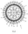
- the stator 6is formed of packets 9 ( figure 2 ) of magnetic sheets 10 having cut notches 11 in which are housed the conductive windings 12 of the stator.
- the packets 9 of sheetsare held apart by axial rods 13.
- the rotor 14 of the motor 5is mounted integral with the shaft 7 by means of rotor arms 15, forming between them grooves and on the ends of which the rotor is hooped.
- the rotor 14is formed of packets 16 ( figure 2 ) magnetic sheets 17 having cut notches 18 in which are housed the conductive windings 19 of the rotor.
- the packets 6 of sheetsare kept apart by spacers at I 20.
- Holes 21 formed axially in the packets 9 of laminations 10 of the statorform ventilation passages for cooling air.
- the spaces 22 between the rotor arms 15also form ventilation passages for cooling air.
- Plates 23 at the front of the leg 3, and 24 and 25 at the rear,define two cooling air supply ducts 26 and 27, respectively at the front and at the rear. the back of the leg 3, and a cooling air recovery duct 28 in the central part of the leg.
- a ferrule 30defines at each axial end of the engine 5 two concentric annular chambers 31 and 32, the chamber 32 surrounding the chamber 31.
- the inner ferrulehas a radius slightly greater than that of the motor shaft 7 and the outer ferrule 30 has a radius slightly less than the distance to the axis of the holes 21.
- the inner chamber 31 formed between the ferrule 30 and the shaft 7forms a distributor for the incoming cooling air.
- This chamberis connected upstream in the ventilation direction, to the cooling air supply duct 27, respectively 26, on the outside of the chamber relative to the axis of the engine, and downstream at the ends of the spaces 22. on the inside of the room.
- the outer chamber 32 formed between the ferrule 30 and the shell 2 of the nacelleforms a collector for the outgoing cooling air.
- This chamberis connected downstream in the ventilation direction, to the cooling air recovery duct 28, on the outside of the chamber with respect to the axis of the engine, and upstream at the ends of the passages formed by the holes 21. .
- a not shown ventilation unitis disposed in the hull of the vessel to ensure cooling of the ventilation air and forced circulation. This unit sends the cold air into the cooling air supply ducts 26 and 27, and recovers the hot air from the cooling air recovery duct 28.
- the cooling airenters the engine from the distribution chambers 31 and leaves it in the collection chambers 32. From the chambers 31, the air circulates axially in the spaces 22 towards the center of the engine (arrow F1 on the figure 2 ), while being distributed radially as and between the packets 16 of magnetic sheets 17 of the rotor and between the radial spacers 20 (arrow F2).
- the cooling airthen passes through the air gap 33 of the motor, between the rotor 14 and the stator 6, then flows between the packets 9 of the magnetic laminations 10 of the stator and between the axial rods 13 (arrow F3).
- the cooling airthen enters the holes 21 and again flows axially from one hole to another to the chambers 32 (arrow F4).
Landscapes
- Engineering & Computer Science (AREA)
- Power Engineering (AREA)
- Chemical & Material Sciences (AREA)
- Combustion & Propulsion (AREA)
- Mechanical Engineering (AREA)
- Ocean & Marine Engineering (AREA)
- Motor Or Generator Cooling System (AREA)
- Iron Core Of Rotating Electric Machines (AREA)
Abstract
Translated fromFrenchDescription
Translated fromFrenchLa présente invention concerne une machine électrique tournante, et plus particulièrement une telle machine comprenant, disposés concentriquement depuis l'axe de la machine vers l'extérieur, un arbre, un rotor solidaire de l'arbre et un stator, le rotor et le stator comportant des paquets de tôles magnétiques séparés par des moyens d'écartement.The present invention relates to a rotating electrical machine, and more particularly to such a machine comprising, arranged concentrically from the axis of the machine to the outside, a shaft, a rotor integral with the shaft and a stator, the rotor and the stator comprising bundles of magnetic sheets separated by spacing means.
De telles machines sont bien connues dans la technique, qu'il s'agisse de génératrices ou de moteurs, par exemple de moteurs asynchrones.Such machines are well known in the art, whether they are generators or motors, for example asynchronous motors.
Un des problèmes soulevés par l'utilisation de ces machines est celui de leur refroidissement. Elles dégagent en effet une quantité de chaleur relativement importante, essentiellement du fait des pertes par effet joule, chaleur qu'il y a lieu d'évacuer pour permettre à la machine de fonctionner à une température acceptable. Ce problème est particulièrement aigu lorsque ces machines doivent fonctionner dans un espace confiné, comme cela est notamment le cas des moteurs électriques de navire logés en nacelle.One of the problems raised by the use of these machines is that of their cooling. They give off a relatively large amount of heat, mainly due to Joule losses, heat that must be removed to allow the machine to operate at an acceptable temperature. This problem is particularly acute when these machines must operate in a confined space, as is the case in particular of the electric engines of ship housed in nacelle.
Une première solution a été de créer un flux d'air de refroidissement axial, depuis une extrémité axiale de la machine jusqu'à l'extrémité opposée. L'inconvénient de cet agencement réside dans le gradient axial de température, celle étant plus élevée du côté de la sortie d'air que du côté de l'entrée.A first solution has been to create an axial cooling air flow from one axial end of the machine to the opposite end. The disadvantage of this arrangement lies in the axial temperature gradient, that being higher on the side of the air outlet than on the side of the inlet.
On a également proposé de réaliser une entrée d'air de refroidissement à chaque extrémité axiale de la machine. Mais, à défaut de contrôler efficacement le trajet suivi par l'air, on obtient alors un gradient de température dans les directions radiale et circonférentielle.It has also been proposed to provide a cooling air inlet at each axial end of the machine. But, failing to effectively control the path followed by the air, we then obtain a temperature gradient in the radial and circumferential directions.
La présente invention vise à palier ces inconvénients.The present invention aims to overcome these disadvantages.
Plus particulièrement, l'invention a pour but de fournir un système de ventilation de machine électrique tournante qui limite les gradients de température.More particularly, the invention aims to provide a rotating electrical machine ventilation system that limits the temperature gradients.
A cet effet, l'invention a tout d'abord pour objet une machine électrique tournante comprenant, disposés concentriquement depuis l'axe de la machine vers l'extérieur, un arbre, un rotor solidaire de l'arbre et un stator, le rotor et le stator comportant des paquets de tôles magnétiques séparés par des moyens d'écartement, cette machine comprenant :
- des moyens d'amenée d'air pour amener de l'air de ventilation à pénétrer dans la machine axialement dans des premiers moyens de circulation d'air aptes à permettre une circulation axiale de l'air de ventilation au niveau du rotor ;
- des deuxièmes moyens de circulation d'air aptes à permettre une circulation axiale de l'air de ventilation au niveau du stator ;
- des moyens de récupération d'air pour collecter l'air de ventilation sortant des deuxièmes moyens de circulation d'air ;
- axialement dans lesdits premiers moyens de circulation d'air ;
- radialement entre lesdits paquets de tôles du rotor, puis du stator, et entre leurs moyens d'écartement respectifs ;
- axialement dans lesdits deuxièmes moyens de circulation d'air.
- air supply means for supplying ventilation air to enter the machine axially in first air circulation means able to allow axial circulation of the ventilation air at the rotor;
- second air circulation means adapted to allow axial circulation of the ventilation air at the stator;
- air recovery means for collecting the ventilation air leaving the second air circulation means;
- axially in said first air circulation means;
- radially between said laminations of the rotor, then the stator, and between their respective spacing means;
- axially in said second air circulation means.
Dans une machine selon l'invention, la circulation de l'air de refroidissement se fait donc pour partie axialement, selon un tronçon de trajet au voisinage de l'axe et un autre tronçon vers l'extérieur de la machine, et pour partie radialement entre le tronçon au voisinage de l'axe et le tronçon extérieur. La circulation d'air radiale se répartissant entre tous les paquets de tôles, l'ensemble de la machine est refroidi efficacement et une bonne homogénéité de température est obtenue.In a machine according to the invention, the circulation of the cooling air thus occurs partly axially, along a path section in the vicinity of the axis and another section towards the outside of the machine, and partly radially. between the section in the vicinity of the axis and the outer section. The radial air flow is distributed among all the packets of plates, the whole of the machine is effectively cooled and a good homogeneity of temperature is obtained.
Dans un mode de réalisation particulier, lesdits moyens d'amenée d'air sont agencés pour amener l'air de ventilation aux deux extrémités axiales de la machine et lesdits moyens de récupération d'air sont agencés pour collecter également l'air de ventilation aux deux extrémités axiales de la machine.In a particular embodiment, said air supply means are arranged to bring the ventilation air to the two axial ends of the machine and said air recovery means are arranged to also collect the ventilation air at the ends of the machine. two axial ends of the machine.
On adopte donc ici la double entrée d'air connue en elle-même dans l'art antérieur.Here we adopt the double air inlet known in itself in the prior art.
Egalement dans un mode de réalisation particulier, lesdits premiers moyens de circulation d'air comprennent des trous percés axialement dans les paquets de tôles du rotor.Also in a particular embodiment, said first air flow means comprise holes drilled axially in the laminations of the rotor.
En variante, ou en combinaison, lesdits premiers moyens de circulation d'air comprennent des espaces ménagés entre l'arbre et le rotor.Alternatively, or in combination, said first air flow means comprise spaces formed between the shaft and the rotor.
Plus particulièrement, lesdits espaces ménagés entre l'arbre et le rotor peuvent comprendre des cannelures à la périphérie desquelles les tôles de rotor sont frettées.More particularly, said spaces formed between the shaft and the rotor may comprise grooves at the periphery of which the rotor plates are hooped.
Egalement dans un mode de réalisation particulier, lesdits deuxièmes moyens de circulation d'air comprennent des trous percés axialement dans les paquets de tôles du stator.Also in a particular embodiment, said second air flow means comprise holes drilled axially in the stator laminations.
Ce mode de réalisation est particulièrement adapté au cas où le stator de la machine est fretté dans un carter extérieur, comme c'est le cas d'un moteur de navire en nacelle, dont le stator est fretté dans l'enveloppe de la nacelle. Il n'y a en effet, dans ce cas, pas de possibilité de circulation d'air de refroidissement à l'extérieur du moteur.This embodiment is particularly suitable in the case where the stator of the machine is hooped in an outer casing, as is the case of a nacelle ship engine, whose stator is shrunk into the shell of the nacelle. There is indeed, in this case, no possibility of cooling air circulation outside the engine.
Dans un autre mode de réalisation, lesdits deuxièmes moyens de circulation d'air comprennent des espaces ménagés à la périphérie extérieure des paquets de tôles du stator.In another embodiment, said second air circulation means comprise spaces at the outer periphery of the stator laminations.
Il peut s'agir d'un volume annulaire ménagé tout autour de la machine ou de découpes formées à la périphérie extérieure des paquets de tôles du stator.It may be an annular volume formed around the machine or blanks formed at the outer periphery of the stator laminations.
Egalement dans un mode de réalisation particulier, lesdits moyens d'écartement comprennent des entretoises radiales.Also in a particular embodiment, said spacer means comprise radial spacers.
Dans un autre mode de réalisation, lesdits moyens d'écartement comprennent des tiges axiales.In another embodiment, said spacing means comprise axial rods.
Ces deux derniers modes de réalisation peuvent d'ailleurs être combinés, les paquets de tôles du rotor, par exemple, étant séparés par des entretoises radiales, tandis que les paquets de tôles du stator sont séparés par des tiges axiales.These last two embodiments may also be combined, the rotor laminations, for example, being separated by radial spacers, while the stator laminations are separated by axial rods.
Egalement dans un mode de réalisation particulier, lesdits moyens d'amenée d'air comprennent au moins une chambre de distribution annulaire formée à une extrémité de la machine et lesdits moyens de récupération d'air comprennent une chambre de collecte annulaire entourant ladite chambre de distribution.Also in a particular embodiment, said air supply means comprise at least one annular distribution chamber formed at one end of the machine and said air recovery means comprise an annular collection chamber surrounding said distribution chamber .
Dans le cas d'une machine à double entrée d'air, une chambre de distribution annulaire et une chambre de collecte annulaire concentriques sont prévues à chaque extrémité radiale de la machine.In the case of a dual air inlet machine, an annular distribution chamber and a concentric annular collection chamber are provided at each radial end of the machine.
L'invention a également pour objet un navire comportant un propulseur en nacelle équipé d'une machine telle que décrite ci-dessus.The invention also relates to a vessel comprising a nacelle propellant equipped with a machine as described above.
On décrira maintenant, à titre d'exemple non limitatif, un mode de réalisation particulier de l'invention, en référence aux dessins schématiques annexés dans lesquels :
- la
figure 1 est une vue en perspective éclatée d'une nacelle de propulsion de navire comportant un moteur selon l'invention ; - la
figure 2 est une vue en perspective d'un secteur angulaire de cette nacelle ; et - la
figure 3 est une vue en coupe transversale, perpendiculaire à l'axe, de cette nacelle.
- the
figure 1 is an exploded perspective view of a ship propulsion nacelle comprising a motor according to the invention; - the
figure 2 is a perspective view of an angular sector of this nacelle; and - the
figure 3 is a cross-sectional view, perpendicular to the axis, of this nacelle.
La nacelle 1 de la
La nacelle 1 reçoit de façon coaxiale un moteur électrique 5 dont le stator 6 est fretté dans l'enveloppe 2. L'arbre 7 du moteur 5 est généralement coaxial à l'enveloppe 2 de la nacelle et porte, à l'arrière de cette dernière, une hélice 8.The
Le stator 6 est formé de paquets 9 (
Le rotor 14 du moteur 5 est monté solidaire de l'arbre 7 par l'intermédiaire de bras 15 de rotor, formant entre eux des cannelures et sur les extrémités desquels le rotor est fretté. Le rotor 14 est formé de paquets 16 (
Des trous 21 formés axialement dans les paquets 9 de tôles 10 du stator forment des passages de ventilation pour de l'air de refroidissement. De même, les espaces 22 ménagés entre les bras 15 de rotor forment également des passages de ventilation pour de l'air de refroidissement.
Des tôles 23 à l'avant de la jambe 3, et 24 et 25 à l'arrière, délimitent deux conduits d'amenée d'air de refroidissement 26 et 27, respectivement à l'avant et à l'arrière de la jambe 3, et un conduit de récupération d'air de refroidissement 28 dans la partie centrale de la jambe.
Une virole en tôle 30 délimite à chaque extrémité axiale du moteur 5 deux chambres annulaires concentriques 31 et 32, la chambre 32 entourant la chambre 31. La virole intérieure a un rayon légèrement supérieur à celui de l'arbre moteur 7 et la virole 30 extérieure a un rayon légèrement inférieur à la distance à l'axe des trous 21.A
La chambre intérieure 31 formée entre la virole 30 et l'arbre 7 forme un distributeur pour l'air de refroidissement entrant. Cette chambre est reliée en amont dans le sens de ventilation, au conduit d'amenée d'air de refroidissement 27, respectivement 26, du côté extérieur de la chambre par rapport à l'axe du moteur, et en aval aux extrémités des espaces 22 du côté intérieur de la chambre.The
La chambre extérieure 32 formée entre la virole 30 et l'enveloppe 2 de la nacelle forme un collecteur pour l'air de refroidissement sortant. Cette chambre est reliée en aval dans le sens de ventilation, au conduit de récupération d'air de refroidissement 28, du côté extérieur de la chambre par rapport à l'axe du moteur, et en amont aux extrémités des passages formés par les trous 21.The
Une centrale de ventilation non représentée est disposée dans la coque du navire pour assurer le refroidissement de l'air de ventilation et sa circulation forcée. Cette centrale envoie l'air froid dans les conduits d'amenée d'air de refroidissement 26 et 27, et récupère l'air chaud du conduit de récupération d'air de refroidissement 28.A not shown ventilation unit is disposed in the hull of the vessel to ensure cooling of the ventilation air and forced circulation. This unit sends the cold air into the cooling
L'air de refroidissement pénètre dans le moteur depuis les chambres de distribution 31 et en ressort dans les chambres de collecte 32. Depuis les chambres 31, l'air circule axialement dans les espaces 22 en direction du centre du moteur (flèche F1 sur la
L'air de refroidissement traverse ensuite l'entrefer 33 du moteur, entre le rotor 14 et le stator 6, puis circule entre les paquets 9 de tôles magnétiques 10 du stator et entre les tiges axiales 13 (flèche F3).The cooling air then passes through the
L'air de refroidissement pénètre ensuite dans les trous 21 et circule de nouveau axialement d'un trou à l'autre jusqu'aux chambres 32 (flèche F4).The cooling air then enters the
Claims (10)
Translated fromFrencheten ce que la machine électrique (5) comprend :
andin that the electric machine (5) comprises:
Applications Claiming Priority (1)
| Application Number | Priority Date | Filing Date | Title |
|---|---|---|---|
| FR0851469AFR2928499B1 (en) | 2008-03-06 | 2008-03-06 | ROTATING ELECTRIC MACHINE VENTILATION SYSTEM |
Publications (2)
| Publication Number | Publication Date |
|---|---|
| EP2098447A1true EP2098447A1 (en) | 2009-09-09 |
| EP2098447B1 EP2098447B1 (en) | 2016-06-01 |
Family
ID=39929875
Family Applications (1)
| Application Number | Title | Priority Date | Filing Date |
|---|---|---|---|
| EP09154352.0AActiveEP2098447B1 (en) | 2008-03-06 | 2009-03-04 | Ventilation system of a rotating electric machine |
Country Status (3)
| Country | Link |
|---|---|
| EP (1) | EP2098447B1 (en) |
| KR (1) | KR101628357B1 (en) |
| FR (1) | FR2928499B1 (en) |
Cited By (6)
| Publication number | Priority date | Publication date | Assignee | Title |
|---|---|---|---|---|
| CN102780318A (en)* | 2012-08-15 | 2012-11-14 | 中电电机股份有限公司 | Ventilation structure for motor air-water cooler |
| US9902478B2 (en) | 2014-06-03 | 2018-02-27 | Rolls-Royce Aktiebolag | Pod propulsion device and a method for cooling such |
| EP2949574B1 (en) | 2014-05-30 | 2018-07-11 | ABB Schweiz AG | Pod propulsion unit of a ship |
| WO2019020358A1 (en)* | 2017-07-24 | 2019-01-31 | Siemens Aktiengesellschaft | Electric motor and ship propulsion device |
| CN110297513A (en)* | 2019-07-04 | 2019-10-01 | 哈尔滨理工大学 | The cooling system and temperature control method that cooling branch inhibits motor temperature rise are adjusted based on operating condition adjustment procedure |
| CN110380559A (en)* | 2018-04-13 | 2019-10-25 | 元山科技工业股份有限公司 | Motor |
Families Citing this family (1)
| Publication number | Priority date | Publication date | Assignee | Title |
|---|---|---|---|---|
| KR20250022503A (en)* | 2023-08-08 | 2025-02-17 | 에이치디현대일렉트릭 주식회사 | Pod drive |
Citations (7)
| Publication number | Priority date | Publication date | Assignee | Title |
|---|---|---|---|---|
| DE720154C (en)* | 1936-03-01 | 1942-04-25 | Siemens Ag | Ventilation arrangement for electrical machines, especially turbo-generators |
| US2887593A (en)* | 1955-09-21 | 1959-05-19 | Bbc Brown Boveri & Cie | Turbo-generator with gas cooling in closed cycle |
| JP2000278914A (en)* | 1999-03-26 | 2000-10-06 | Mitsubishi Electric Corp | Rotating electric machine |
| US6312298B1 (en)* | 1997-07-21 | 2001-11-06 | Siemens Aktiengesellschaft | Electromotive drive system for a ship |
| WO2003047962A2 (en)* | 2001-11-29 | 2003-06-12 | Siemens Aktiengesellschaft | Ship propulsion system |
| DE10310307A1 (en)* | 2002-03-18 | 2003-10-02 | Alstom Switzerland Ltd | Electrical machine with integrated power electronic device |
| EP1408600A2 (en)* | 2002-10-11 | 2004-04-14 | Siemens Westinghouse Power Corporation | Dynamoelectric machine with arcuate heat exchanger and related methods |
Family Cites Families (2)
| Publication number | Priority date | Publication date | Assignee | Title |
|---|---|---|---|---|
| JP3259905B2 (en)* | 1998-03-26 | 2002-02-25 | 川崎重工業株式会社 | Pod propellers and ships equipped with these pod propellers |
| US6582257B1 (en)* | 2001-12-17 | 2003-06-24 | Alstom | Propulsion unit |
- 2008
- 2008-03-06FRFR0851469Apatent/FR2928499B1/enactiveActive
- 2009
- 2009-03-04EPEP09154352.0Apatent/EP2098447B1/enactiveActive
- 2009-03-06KRKR1020090019356Apatent/KR101628357B1/enactiveActive
Patent Citations (7)
| Publication number | Priority date | Publication date | Assignee | Title |
|---|---|---|---|---|
| DE720154C (en)* | 1936-03-01 | 1942-04-25 | Siemens Ag | Ventilation arrangement for electrical machines, especially turbo-generators |
| US2887593A (en)* | 1955-09-21 | 1959-05-19 | Bbc Brown Boveri & Cie | Turbo-generator with gas cooling in closed cycle |
| US6312298B1 (en)* | 1997-07-21 | 2001-11-06 | Siemens Aktiengesellschaft | Electromotive drive system for a ship |
| JP2000278914A (en)* | 1999-03-26 | 2000-10-06 | Mitsubishi Electric Corp | Rotating electric machine |
| WO2003047962A2 (en)* | 2001-11-29 | 2003-06-12 | Siemens Aktiengesellschaft | Ship propulsion system |
| DE10310307A1 (en)* | 2002-03-18 | 2003-10-02 | Alstom Switzerland Ltd | Electrical machine with integrated power electronic device |
| EP1408600A2 (en)* | 2002-10-11 | 2004-04-14 | Siemens Westinghouse Power Corporation | Dynamoelectric machine with arcuate heat exchanger and related methods |
Cited By (9)
| Publication number | Priority date | Publication date | Assignee | Title |
|---|---|---|---|---|
| CN102780318A (en)* | 2012-08-15 | 2012-11-14 | 中电电机股份有限公司 | Ventilation structure for motor air-water cooler |
| CN102780318B (en)* | 2012-08-15 | 2014-04-09 | 中电电机股份有限公司 | Ventilation structure for motor air-water cooler |
| EP2949574B1 (en) | 2014-05-30 | 2018-07-11 | ABB Schweiz AG | Pod propulsion unit of a ship |
| US9902478B2 (en) | 2014-06-03 | 2018-02-27 | Rolls-Royce Aktiebolag | Pod propulsion device and a method for cooling such |
| US11383808B2 (en) | 2014-06-03 | 2022-07-12 | Kongsberg Maritime Sweden Ab | Pod propulsion device and a method for cooling such |
| WO2019020358A1 (en)* | 2017-07-24 | 2019-01-31 | Siemens Aktiengesellschaft | Electric motor and ship propulsion device |
| CN110380559A (en)* | 2018-04-13 | 2019-10-25 | 元山科技工业股份有限公司 | Motor |
| CN110297513A (en)* | 2019-07-04 | 2019-10-01 | 哈尔滨理工大学 | The cooling system and temperature control method that cooling branch inhibits motor temperature rise are adjusted based on operating condition adjustment procedure |
| CN110297513B (en)* | 2019-07-04 | 2020-01-03 | 哈尔滨理工大学 | Cooling system for regulating cooling branch to inhibit motor temperature rise based on working condition adaptation method and temperature control method |
Also Published As
| Publication number | Publication date |
|---|---|
| EP2098447B1 (en) | 2016-06-01 |
| KR20090096366A (en) | 2009-09-10 |
| KR101628357B1 (en) | 2016-06-08 |
| FR2928499A1 (en) | 2009-09-11 |
| FR2928499B1 (en) | 2011-12-23 |
Similar Documents
| Publication | Publication Date | Title |
|---|---|---|
| EP2098447B1 (en) | Ventilation system of a rotating electric machine | |
| EP2311172B1 (en) | Rotating electrical machine | |
| EP3390831B1 (en) | Electrical centrifugal compressor for turbomachine or aircraft | |
| EP3353879B1 (en) | Electrical rotating machine comprising a rotor and a stator for the passage of a fluid | |
| WO2020174176A1 (en) | Rotary electric machine having a circuit for cooling the magnets via the shaft | |
| FR2474780A1 (en) | LIQUID COOLING CIRCUIT FOR INDUCTION MOTORS | |
| FR2499647A1 (en) | IMPROVEMENTS ON HERMETIC MAGNETIC COUPLINGS | |
| EP3516757A1 (en) | Electrical machine cooled by a dual-flow impeller | |
| FR3105631A1 (en) | Stator for electric motor | |
| EP2324560A2 (en) | Connector flange for an electric machine with stator windings | |
| FR2930381A1 (en) | ELECTRIC MACHINE WITH DOUBLE VENTILATION SEPARATE | |
| WO2021240101A1 (en) | Rotor for an electric motor provided with a cooling circuit | |
| WO2017121930A1 (en) | Rotary electric machine with improved cooling | |
| FR3056356B1 (en) | SLEEVE AND SHAFT OF ELECTRIC MACHINE | |
| EP4167440A1 (en) | Wound rotor for an electric motor provided with a cooling circuit | |
| FR3015144A1 (en) | METHOD FOR COOLING AN ELECTRIC GENERATOR AND DEVICE FOR CARRYING OUT SAID METHOD | |
| EP4040642B1 (en) | Closed engine cooled by fan, improved by making it symmetric | |
| EP4324076B1 (en) | Electric motor designed to allow a better removal of the heat generated when it is operating | |
| EP4115501A1 (en) | Electric motor provided with a cooling circuit | |
| FR2838252A1 (en) | ELECTRIC MACHINE, ESPECIALLY GENERATOR FOR WIND TURBINE, COMPRISING COOLING FINS EXTENDING SUBSTANTIALLY PERPENDICULAR TO THE ROTATION AXIS OF THE ROTOR | |
| FR3028689A3 (en) | ELECTRIC MOTOR COMPRISING A ROTOR COOLING CIRCUIT. | |
| FR3034583A1 (en) | COOLING DEVICE FOR ELECTRIC MACHINE. | |
| FR3155985A1 (en) | Axial flux electric motor including closed-circuit air cooling | |
| WO2020174183A1 (en) | Rotating electrical machine having a circuit for cooling magnets by the shaft | |
| FR2987518A1 (en) | CLOSED ELECTRIC MOTOR COMPRISING A THERMAL EXCHANGER. |
Legal Events
| Date | Code | Title | Description |
|---|---|---|---|
| PUAI | Public reference made under article 153(3) epc to a published international application that has entered the european phase | Free format text:ORIGINAL CODE: 0009012 | |
| AK | Designated contracting states | Kind code of ref document:A1 Designated state(s):AT BE BG CH CY CZ DE DK EE ES FI FR GB GR HR HU IE IS IT LI LT LU LV MC MK MT NL NO PL PT RO SE SI SK TR | |
| AX | Request for extension of the european patent | Extension state:AL BA RS | |
| 17P | Request for examination filed | Effective date:20100201 | |
| AKX | Designation fees paid | Designated state(s):DE FI FR SE | |
| 17Q | First examination report despatched | Effective date:20120329 | |
| RAP1 | Party data changed (applicant data changed or rights of an application transferred) | Owner name:GE ENERGY POWER CONVERSION FRANCE SAS | |
| REG | Reference to a national code | Ref country code:DE Ref legal event code:R079 Ref document number:602009038975 Country of ref document:DE Free format text:PREVIOUS MAIN CLASS: B63H0021170000 Ipc:B63H0005125000 | |
| GRAP | Despatch of communication of intention to grant a patent | Free format text:ORIGINAL CODE: EPIDOSNIGR1 | |
| RIC1 | Information provided on ipc code assigned before grant | Ipc:H02K 1/32 20060101ALI20151204BHEP Ipc:H02K 9/04 20060101ALI20151204BHEP Ipc:H02K 1/20 20060101ALI20151204BHEP Ipc:B63H 5/125 20060101AFI20151204BHEP | |
| INTG | Intention to grant announced | Effective date:20160111 | |
| GRAS | Grant fee paid | Free format text:ORIGINAL CODE: EPIDOSNIGR3 | |
| GRAA | (expected) grant | Free format text:ORIGINAL CODE: 0009210 | |
| AK | Designated contracting states | Kind code of ref document:B1 Designated state(s):DE FI FR SE | |
| REG | Reference to a national code | Ref country code:DE Ref legal event code:R096 Ref document number:602009038975 Country of ref document:DE | |
| PG25 | Lapsed in a contracting state [announced via postgrant information from national office to epo] | Ref country code:SE Free format text:LAPSE BECAUSE OF FAILURE TO SUBMIT A TRANSLATION OF THE DESCRIPTION OR TO PAY THE FEE WITHIN THE PRESCRIBED TIME-LIMIT Effective date:20160601 | |
| REG | Reference to a national code | Ref country code:DE Ref legal event code:R097 Ref document number:602009038975 Country of ref document:DE | |
| REG | Reference to a national code | Ref country code:FR Ref legal event code:PLFP Year of fee payment:9 | |
| PLBE | No opposition filed within time limit | Free format text:ORIGINAL CODE: 0009261 | |
| STAA | Information on the status of an ep patent application or granted ep patent | Free format text:STATUS: NO OPPOSITION FILED WITHIN TIME LIMIT | |
| 26N | No opposition filed | Effective date:20170302 | |
| REG | Reference to a national code | Ref country code:DE Ref legal event code:R119 Ref document number:602009038975 Country of ref document:DE | |
| PG25 | Lapsed in a contracting state [announced via postgrant information from national office to epo] | Ref country code:DE Free format text:LAPSE BECAUSE OF NON-PAYMENT OF DUE FEES Effective date:20171003 | |
| REG | Reference to a national code | Ref country code:FR Ref legal event code:PLFP Year of fee payment:10 | |
| PGFP | Annual fee paid to national office [announced via postgrant information from national office to epo] | Ref country code:FI Payment date:20250218 Year of fee payment:17 | |
| PGFP | Annual fee paid to national office [announced via postgrant information from national office to epo] | Ref country code:FR Payment date:20250218 Year of fee payment:17 |