EP2098368B1 - Method for individualising the sides of a printed product - Google Patents
Method for individualising the sides of a printed productDownload PDFInfo
- Publication number
- EP2098368B1 EP2098368B1EP20090152977EP09152977AEP2098368B1EP 2098368 B1EP2098368 B1EP 2098368B1EP 20090152977EP20090152977EP 20090152977EP 09152977 AEP09152977 AEP 09152977AEP 2098368 B1EP2098368 B1EP 2098368B1
- Authority
- EP
- European Patent Office
- Prior art keywords
- printing
- production
- printed
- printed product
- control unit
- Prior art date
- Legal status (The legal status is an assumption and is not a legal conclusion. Google has not performed a legal analysis and makes no representation as to the accuracy of the status listed.)
- Not-in-force
Links
- 238000000034methodMethods0.000titleclaimsdescription66
- 238000007639printingMethods0.000claimsdescription179
- 238000004519manufacturing processMethods0.000claimsdescription97
- 239000000463materialSubstances0.000claimsdescription60
- 239000000758substrateSubstances0.000claimsdescription18
- 238000007645offset printingMethods0.000claimsdescription8
- 238000007641inkjet printingMethods0.000claimsdescription5
- 238000007648laser printingMethods0.000claimsdescription2
- 230000008569processEffects0.000description19
- 238000002360preparation methodMethods0.000description9
- 238000003860storageMethods0.000description6
- 230000001276controlling effectEffects0.000description4
- 238000009420retrofittingMethods0.000description4
- 230000003068static effectEffects0.000description4
- 230000008859changeEffects0.000description3
- 238000002372labellingMethods0.000description3
- 238000012545processingMethods0.000description3
- 238000006243chemical reactionMethods0.000description2
- 238000010586diagramMethods0.000description2
- 238000005516engineering processMethods0.000description2
- 238000007646gravure printingMethods0.000description2
- 239000011159matrix materialSubstances0.000description2
- 230000006855networkingEffects0.000description2
- 230000001360synchronised effectEffects0.000description2
- 239000000853adhesiveSubstances0.000description1
- 230000001070adhesive effectEffects0.000description1
- 230000002457bidirectional effectEffects0.000description1
- 230000005540biological transmissionEffects0.000description1
- 230000015572biosynthetic processEffects0.000description1
- 230000001427coherent effectEffects0.000description1
- 238000004891communicationMethods0.000description1
- 150000001875compoundsChemical class0.000description1
- 238000010924continuous productionMethods0.000description1
- 238000012937correctionMethods0.000description1
- 230000001419dependent effectEffects0.000description1
- 230000003993interactionEffects0.000description1
- 238000012806monitoring deviceMethods0.000description1
- 239000002245particleSubstances0.000description1
- 230000001105regulatory effectEffects0.000description1
- 230000004044responseEffects0.000description1
- 230000000717retained effectEffects0.000description1
- 239000002904solventSubstances0.000description1
Images


Classifications
- B—PERFORMING OPERATIONS; TRANSPORTING
- B41—PRINTING; LINING MACHINES; TYPEWRITERS; STAMPS
- B41F—PRINTING MACHINES OR PRESSES
- B41F33/00—Indicating, counting, warning, control or safety devices
- B41F33/0009—Central control units
Definitions
- the inventionrelates to a method for individualizing pages of a printed product according to the preamble of claim 1.
- a method for controlling or regulating a process for the production of printed copiesis known, being printed for the production of printed copies of a substrate and then further processed, wherein the printing material for printing a static or unchanging printed image is moved by at least one printing unit of a printing press, the printing material is printed with dynamic or variable control data or control data, wherein the printing material for this purpose is moved by at least one, synchronized with the or each printing unit printing device, and wherein the control data or control data read from or on the substrate and the control or Control of the printing process and / or further processing process can be used.
- a method for printing printed matter customized with logistic printing elementswherein at least one printing image printed in a printing machine is customized by inserting at least one dynamic logistics print image element, whereby data of the or each particular static print image is combined with data of the or each dynamic logistic print image element that the or each print image and the or each logistics print pixel are printed inline, and that the data of the or each logistics print pixel is automatically updated via a data match between a database provided by a logistics provider prior to printing the individualized print products with the or each logistics print pixel become.
- a method for printing a printing substratewherein the printing material for printing a static or fixed print image is moved by at least one printing unit, wherein the printing material for individualizing the static printed image with at least one dynamic or variable printed image by at least one, to or each printing unit inline switched printing device is moved, wherein as printing devices for printing the dynamic or variable printed image z.
- inkjet or inkjet printing devicesare used.
- DE 10 2006 016 065 A1is an additional device for a working according to the offset printing principle printing machine, in particular web offset newspaper printing machine, known in the form of an inkjet printing system, wherein at least one inkjet printhead mounted on a crosshead transversely to the printing direction in a working position to a paper web within the printing press, in particular is arranged in or at least close to a printing unit in order to allow additional, also variable information as well as frequently changing information during a print run anywhere in the printed matter produced by the printing press can be added.
- a printing machinewith a working with material printing forms printing unit for printing during the printing period unchangeable first information field on a recording medium, with a controllable printing unit for printing a second information field with variable within the printing period information and with a controllable printing unit controlling unit, wherein the controllable printing unit is a dot matrix printing device, the dot matrix printing device preferably being an ink jet printing head.
- a method for converting a web-fed printing press from an ongoing production of a first printed product to a subsequent production of a second printed productthe first printed product being produced from a web of web fed currently the first web of material and the second printed product from a web press subsequently to be supplied second web, wherein these webs differ in their respective width and / or in the grade and / or grammage of their material from each other, wherein a time for producing a compound of the second material web with the first material web of at least the current production of the first
- This decisionis made in dependence on the production data relating to the second printed product, the production data being made available to the control unit. It is provided that characteristic data of the second material web is detected by reading out a barcode label attached to this material web with a barcode reader connected to the control unit by data technology and made available to this control unit.
- the EP 0 710 558 A1describes a web-fed rotary printing machine with an adjustable reel splicer for receiving printing material webs with different widths, with pressure cylinders adjusable in a printing unit to form pressure points and with an adjustable folder, wherein the width of the roll changer, the position of the printing cylinder and components of the folder for switching the production from a first printed product to a second printed product during the machine run are adjusted automatically and coordinated with each other, the components of a folder, in particular a jaw opening and an expansion of a collecting cylinder, depending on the changed page number of the printed product are adjustable.
- the conversion of productionis based on calculations and commands issued by the reel splitter.
- a jaw cylinder for a printing machinewherein an adjustment of a working distance of its jaws via a servomotor control in response to adjustable, the set working distance determining control variables, in particular the number of pages of the printed product and optionally the surface specific weight of the paper takes place.
- WO 2005/077797 A2discloses a method for storing unprepared and prepared material rolls of a web-processing machine in a warehouse, wherein a material flow system information for forecasting consumption data for an upcoming production period or forecast consumption data are fed and where in a sub-process based on the forecast consumption data and the current inventory a determination a stock strategy takes place.
- a printing companywhich has at least one printing press, z.
- Example, a web press, and a material supply systemshould have, the material supply system supplies the printing machine with a plurality of each formed as a substrate material webs, these webs are to be printed in the web press sequentially.
- the material supply systemsupplies the printing machine with a plurality of each formed as a substrate material webs, these webs are to be printed in the web press sequentially.
- the material webs to be printed in the printing pressare each preferably designed as a paper web.
- Each of the material webs assigned to a specific printed product to be produced or at least a part of themis preferably wound into a roll in each case.
- each rollforms a partial web of the material required for the execution of the respective print job.
- the individual partial websare the printing press z. B.
- the partial webs lined up for the same productionform a coherent material web with a length determined essentially as a function of the support of the printed product to be produced. Moreover, it can be provided that several belonging to the same material web sub-webs, z as different strands. B. fed from different reel changers of the printing press, are fed to the same folder simultaneously.
- the printing machineworks z.
- Examplein a gravure printing method or in a planographic printing method, in particular in an offset printing method, wherein the offset printing method may be a conventional, ie a dampening wet offset printing method or a dry offset printing method without fountain solution.
- the printed product to be produced with the printing pressis preferably produced in multicolor printing, in particular in four-color printing.
- a width of a material web to be printed in the printing presscan be up to 4,500 mm, in particular when the gravure printing method is used.
- the width of the material webis usually in the range between 1,000 mm and 2,400 mm, preferably between 1,200 mm and 2,400 mm.
- the partial webs required to execute a print jobcan each have a length in the range of several thousand meters.
- a new roll of newsprint paper in its condition delivered by the paper millmay have a partial web having a length in the range between 18,000 m and 25,000 m.
- several of these partial websare required to perform certain print jobs, as a print job z. B. in the production of a newspaper may well involve several tens of thousands of copies.
- a high-performance printing machine with cylinders z. B.double circumference, ie with cylinders with a circumference in the range between 900 mm to 1,400 mm, the circumference z. B.
- each section length z. Ba height of a newspaper page produced in a single hour, for example, about 90,000 Copies of the respective printed product in duplicate and approx. 45,000 copies in collective production.
- Such a printing pressprints a role of the aforementioned type z. B. within 20 minutes, so then ready for uninterrupted continuation of production another sub-web and the printing press must be supplied.
- the inventionis based on the object of providing a method for individualizing pages of a printed product, which simplifies a conversion of a production from a first printed product to a production of a second printed product.
- the achievable with the present inventionconsist in particular in that when changing a production from a first printed product to a production of a second printed product in the printing press not necessarily all printing forms must be replaced, just because an arrangement of the pages produced with these printing forms within the Printed product changes. Rather, at least some printing plates are also in the production of the second printed product without affecting this printed product reusable because their printed image remains unchanged, which saves costs.
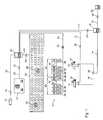
- Fig. 1shows simplified in a block diagram a printing company with at least one printing press 01 and an electronic control unit 02 of a material supply system.
- the printing machine 01is preferably designed as a web-fed printing machine 01 and consists z. B. from several, z. B. two independently producible sections 03; 04, each section 03; 04 preferably several, z. B. four printing towers 06 and at least one folding apparatus 07 has.
- Each printing tower 06is preferably associated with an automatic roll changer 08, wherein each roll changer 08 can simultaneously carry two rolls of a printing material to be supplied to the printing plate 06, namely a first roll which is already involved in a production currently being carried out with the printing press 01, and one another role, which is prepared to be involved in the production once the substrate has been consumed by the first roll.
- Each rollforms a partial web, wherein the roll changer 08 has a device for automatically connecting the partial web of the roll already involved in the current production with the partial web of the production continuing roll. This device interconnecting the partial webs of the roll changer 08 is formed in its preferred embodiment as an adhesive device.
- the roll changers 08each have a control unit, which is connected in each case for carrying out a data exchange via a control line 09 to the control unit 02 of the material supply system.
- each section 03; 04a preferably as a control station 11; 12 trained control unit 11; 12 assigned, wherein at each of these control stations 11; 12 the respective section 03; 04 or even the printing press 01 as a whole can be controlled.
- the control rooms 11; 12are preferably connected via a control line 13 to the control unit 02 of the material supply system.
- the control stations 11; 12each have z.
- an operating unit 31 with a display devicewherein on the control unit 31 data, in particular the respective print job production data, manually entered or z. B. can be selected from a selection list.
- the display device belonging to FIG. 12may also be designed as a so-called touchscreen, wherein a touchscreen is an input device known in computer technology as a touchscreen or touchscreen, so that a selection or input can be made directly at this display device, since functions of the control unit 31 are integrated in this display device.
- the production data, the control center 11, which controls at least the current production of the first printed product; 12are made available by a manual input to the to this control station 11; 12 associated control unit 31 during the current production of the first printed product can be supplemented and / or corrected, so that changes and / or corrections can be considered if necessary.
- the control stations 11; 12are preferably also interconnected with each other via a control line 14, wherein this control line 14 is preferably also connected to an electronic control unit 16 of a production planning system managing at least the production data.
- the control unit 16 of the production planning systemis connected via a control line 17 to the control unit 02 of the material supply system.
- the control unit 16 of the production planning systemcan be connected via a control line 18 to a control unit 19 of an operating data acquisition system.
- a manually guided main bearingis at the control unit 02 of the material supply system via a control line 22, at least one monitor 21 for role demand display and preferably z.
- Balso a control unit for an input and / or selection of data, in particular production data, connected to the control unit 02 of the material supply system.
- the control unit 02 of the material supply systemis connected via a control line 23 also with control and actuating devices of the printing machine 01 associated with daily storage 24 in connection, said control and actuating devices z.
- B.at least one in the Day storage 24 effective transport 26 drive and monitor this transport 26 in their movement.
- the effective in the day camp 24 transport device 26may, for. B. be designed as a driverless transport system (AGV).
- AGVdriverless transport system
- the day storage 24is also managed by the material supply system.
- a roller preparation station 27is provided for preparing the rollers, in which z. B. prepared from the main bearing rollers prepared for their use in a printing process and then stored in the day storage 24.
- the respectively required rollis automatically delivered to the roll preparation station 27 via the material supply system.
- the preparation of the rolls carried out in the roll preparation station 27also includes, in particular, preparing these rolls for a bonding process carried out later in the roll changer 08.
- Rolls processed in the roll preparation station 27are therefore also referred to as glue-prepared rolls.
- a tack-prepared roleis depending on the durability of Klebeborbungung z. B. within 24 or 72 hours to feed the printing process.
- a control unit arranged in the roller preparation station 27 for preparing the rollersis connected via a control line 28 to the control unit 02 of the material supply system.
- the control unit of the roll preparation station 27preferably has an operating unit and a display device (both not shown).
- All control lines 09; 13; 14; 17; 18; 22; 23; 28may also be designed as wireless transmission links and / or preferably the same, z. B. an Ethernet-based communication network belong.
- all control lines 09; 13; 14; 17; 18; 22; 23; 28may be arranged one or more traffic controlling and / or monitoring devices 29, these devices 29 each z. B. are designed as a bidirectional traffic gestattende interface 29. The networking of all previously based on the Fig.
- 1 described system componentsie in particular of the control units 02; 11; 12; 16; 19, by means of Control lines 09; 13; 14; 17; 18; 22; 23; 28 allows data to be exchanged between at least one of the control stations 11; 12 and the production planning system and / or the material supply system and / or can be transferred from the respective roll changer 08 directly to the material supply system.
- control unit 02 of the material supply systemcauses suitable rolls of the printing stock to be kept ready in the day storage 24 for execution of a specific print job and to be transported in time to the respective roll changer 08.
- the control unit 02 of the material supply systemcontrols the processes required to execute a specific print job such that the z. B. from the day storage 24 and / or main stock selected roles of the printing material are used targeted so used that the production to be performed is terminated with the last used to be used role at the end of the print run in a defined manner.
- the determination of the sequence of the rolls to be printed by the control unit 02 of the material supply systemtakes place, in particular, as a function of the minimum length of the partial web determined for the defined completion of production on the last roll to be used, wherein the determination of the minimum length preferably also the intended transport speed taken into account for the web to be printed in the printing press.
- the data networking of the control unit 11; 12 of the printing press 01 with the control unit 02 of the material supply system and / or the control unit 16 of the production planning systemmakes it possible, in particular, for a time for establishing the connection of the second material web with the first material web to be controlled by the control unit 11, which controls at least the current production of the first printed product; 12, dhid R.
- control unit 11; 12can be determined and fixed, wherein the determination takes place in dependence on production data, the control unit 11; 12 by a manual input to a to this control unit 11; 12 belonging control unit 31 or automatically provided by the control unit 16 of the production planning system.
- Fig. 2shows a program mask 42, the z. B. on the display device of one of the control stations 11; 12 is displayed.
- This program mask 42belongs to a program which controls the sequence of the process for retrofitting the web printing press from a current production of a first printed product to a subsequent production of a second printed product, wherein the webs z. B. differ in their respective width and / or in the variety and / or grammage of their material from each other, ie automatically performs a so-called circumference change.
- the program mask 42has z. B. a control panel 43, in which z. B.
- buttons 44 or 46can be determined by an operation of a corresponding button 44 or 46, whether the process of retrofitting the web printing machine from a current production of a first printed product to a subsequent production of a second printed product by an operator manually controlled or automatically run automatically programmatically.
- the button 46 assigned to the automatic sequence of this methodis shown activated.
- the automatic procedure of this procedurebecomes, as in the Fig. 2 exemplified, entered in an input field 47, a residual amount of copies of the first printed product, z. B. - as shown - of 5,000 copies.
- thispreferably flows in one of the control stations 11; 12 program implemented the process of this process for retrofitting the web printing press from a current production of a first printed product to a subsequent production of a second printed product.
- the program mask 42also has z. B. at least one display field 48, in which preferably at least one operating status of various at the end of this process for retrofitting the web press from a current production of a first printed product to a subsequent production of a second printed product participating units of the web press are displayed.
- the displayed operating statusesrelate to successive operating states of at least one reel splitter 08 involved in the method. B. be updated depending on the event.
- the web-fed printing pressis converted from a current production of a first printed product with a first page number to a subsequent production of a second printed article with a second page number, but at least one printing plate used to produce the first printed product is also used to produce the second printed product, then to change a page number of the side of the second printed product produced with the further used printing form with respect to the page number of the page produced with the same printing forme. Therefore, it is desirable to apply a marking, in particular a numbering of the pages of the printed product to be printed on the pages concerned regardless of the printing plates used for the production of the respective printed product, said marking of the relevant page or pages of the printed product to be produced their respective arrangement in this printed product displays.
- an additional device z. B.in the form of an imprint work for use, such an imprinting z. B. an ink printing method or a laser printing method applies.
- Such an imprinteris arranged in the transport direction of the printing material to be printed close to a departure from the respective printing tower 06.
- imprintcan also be a z. Example, be used by the control unit 16 of the production planning system controllable numbering, the numbering the labeling of the sides of the printed product to be produced z. B. imprinted in a high-pressure process on the substrate.
- the respective information content z. B.is provided by the control unit 16 of the production planning system.
- the control unit 16 of the production planning systemu. a. z. B. in the form of a z.
- a pre-press imposition schemewhich side of the printed product to be produced at which position in the printing press, d. H. with which printing forme on which forme cylinder in which printing tower 06 which section 03; 04 of this printing press is printed.
- z. B.double circumference, in which the circumference z. B.
- each section length of the length, in particular height or width of a page of the printed product, in particular a newspaper pagecorresponds to be provided at a certain position in the press information content within a particular production during a rotation of this plate cylinder cyclically recurring , if on the same form cylinder consecutive section lengths z.
- this labelis executed by a during the production of the printing machine in selbiger stationary arranged imprinting.
- the control unit 16 of the production planning systemprovides the respective information content of the marking to be carried out with the respective imprinting device, in particular depending on the imposition scheme determined for a particular production.
- the information content to be provided at a specific position, ie with regard to a specific printing form in the printing pressis preferably provided in a cyclically recurring manner within an ongoing, current production, eg. In the form of a repeating sequence of particular information in current production.
- the marking to be applied to the selected position in the printing pressis preferably a page number of the relevant page of the printed product.
- a plurality of printing platescan be arranged in the axial direction and / or in the circumferential direction of a forme cylinder involved in the production of the printed product, wherein a marking individualizing the relevant page is applied to at least one of the printed pages of the printed product.
- the cycle of the information content provided within a running production at a certain position in the printing pressis thus dependent on the type of printing of the relevant forme cylinder concerned. If the form cylinder in its circumferential direction z. B.
- a plurality of pressure forms arranged at different axial positions of the forme cylinderare each assigned an independently actuatable impression system by the control unit of the production planning system, the information content provided by the control unit of the production planning system at the respective imprinting unit being applied to the page of the printed product to be individualized Marking z. B. is taken from the imposition scheme defined in the prepress, the imposition includes information about the occupancy of the form cylinder involved in the production with printing plates.
- the imposition schemeis preferably stored in the control unit of the production planning system.
- the pre-pressincludes all processes before the actual, running in the printing press printing process such.
- this data contentmay relate to text and / or images to be printed, a layout creation, producing the imposition and the creation of at least one printing form, which mapped the data to be printed on a substrate becomes.
- Fig. 3shows by way of example a working in the ink printing process, for the labeling of pages of the currently produced print product usable imprinting unit 51, in which a printing ink 52, in particular an ink 52, by at least one nozzle 53, preferably by a plurality of nozzles 53 is placed on the substrate 54.
- a printing ink 52in particular an ink 52
- the ink droplets 52 ejected from a container 56, in particular ink containers 56return a path w as far as the printing substrate 54.
- the path w of the droplets 52 from the ink tank 56 to the substrate 54is z. B. in the range between 10 mm and 50 mm, preferably less than 30 mm.
- the individual droplets 52contain, besides color particles, also solvents.
- a sequence of droplets 52continuous jet those drops 52 are retained in the imprinter 51, which should not reach the substrate 54.
- unwanted droplets 52are electrically charged along their path w from the ink container 56 to the printing material 54 during flight through a charging electrode 58.
- the droplets 52which are to reach the printing material 54, remain uncharged.
- a deflection electrode 59directs the charged droplets 52 into a collecting channel 61, from where they are conveyed via a return line 62 and z. B. a filter 63 to the ink tank 56 are returned.
- the nozzle 53 ejecting the ink jet 52must be moved relative to the printing material 54.
- a plurality of such nozzles 53are arranged in a row, wherein each of these nozzles 53 has a nozzle opening for the exit of the droplets 52 has a diameter in the range of z. B. less than 50 microns, wherein the individual arranged in the same row nozzles 53 at a distance of z.
- the pressure generated by the pump 64is preferably variably adjustable.
- the electromechanical transducer 57 used for droplet formationoscillates at a preferably constant frequency preferably in the range of several kilohertz, z. B. in the range between 50 kHz and 80 kHz, in particular in the range between 60 kHz and 70 kHz.
- the printing material 54is arranged from the exit point of the ink jet 52 from the imprinter 51 in a preferably only slightly varying distance in the range between 3 mm and 15 mm, preferably between 6 mm and 10 mm, each with a fluctuation width of less than 2 mm.
- imprints 51may be arranged, namely z. B. in a printable side of the substrate 54 four printing units having printing tower 06 z. B. each an impression unit 51 in association with an axial, a printing plate bearing position of a forme cylinder of one, preferably in the transport direction of the printing material 54 in this printing tower 06 last of these printing units.
- the imprinter 51is preferably in the axial direction of a forme cylinder by a remote control z. B. positionable by driving an actuator, z. B.
Landscapes
- Inking, Control Or Cleaning Of Printing Machines (AREA)
Description
Translated fromGermanDie Erfindung betrifft ein Verfahren zur Individualisierung von Seiten eines Druckproduktes gemäß dem Oberbegriff des Anspruchs 1.The invention relates to a method for individualizing pages of a printed product according to the preamble of claim 1.
Durch die
Durch die
Durch die
Durch die
Durch die
Durch die
Durch die
Die
Durch die
Durch die
Durch die
Nachfolgend wird von einer Druckerei ausgegangen, die über mindestens eine Druckmaschine, z. B. eine Rollendruckmaschine, und ein Materialversorgungssystem verfügen soll, wobei das Materialversorgungssystem die Druckmaschine mit mehreren jeweils als ein Bedruckstoff ausgebildeten Materialbahnen versorgt, wobei diese Materialbahnen in der Rollendruckmaschine nacheinander zu bedrucken sind. Für eine wirtschaftliche Produktion ist es notwendig, in der Druckmaschine ablaufende Prozesse und das Materialversorgungssystem zu einem effektiven Zusammenspiel zu bringen.Below is assumed by a printing company, which has at least one printing press, z. Example, a web press, and a material supply system should have, the material supply system supplies the printing machine with a plurality of each formed as a substrate material webs, these webs are to be printed in the web press sequentially. For economical production, it is necessary to bring processes occurring in the printing press and the material supply system to an effective interplay.
Die in der Druckmaschine zu bedruckenden Materialbahnen sind jeweils vorzugsweise als eine Papierbahn ausgebildet. Jede der jeweils einem bestimmten zu produzierenden Druckprodukt zugeordneten Materialbahnen oder zumindest ein Teil von ihnen ist jeweils vorzugsweise zu einer Rolle gewickelt. Insbesondere wenn das jeweils aus der jeweiligen Materialbahn zu produzierende Druckprodukt eine höhere Auflage, d. h. eine größere Anzahl von Exemplaren aufweist, wie es z. B. bei einer Zeitung mit z. B. mehreren tausend Exemplaren je Ausgabe der Fall ist, sind an der Druckmaschine zur Ausführung eines solchen Druckauftrages sukzessive mehrere Rollen bereitzustellen und in den Druckprozess einzuführen, wobei jede Rolle eine Teilbahn von der zur Ausführung des jeweiligen Druckauftrages benötigten Materialbahn bildet. Die einzelnen Teilbahnen werden der Druckmaschine z. B. eine nach der anderen zur kontinuierlichen Erzeugung der Exemplare des dem Druckauftrag entsprechenden Druckproduktes zugeführt, wobei jeweils vorzugsweise ein Ende einer in der laufenden Produktion z. B. bereits nahezu vollständig bedruckten Teilbahn und ein Anfang einer nachfolgend zur Produktion zu bringenden Teilbahn zusammengefügt werden. In ihrer Summe bilden die für dieselbe Produktion aneinandergereihten Teilbahnen eine zusammenhängende Materialbahn mit einer im Wesentlichen in Abhängigkeit von der Auflage des zu erzeugenden Druckproduktes festgelegten Länge. Überdies kann vorgesehen sein, dass mehrere zu derselben Materialbahn gehörende Teilbahnen, die als unterschiedliche Stränge z. B. von verschiedenen Rollenwechslern der Druckmaschine zugeführt werden, gleichzeitig demselben Falzapparat zugeführt werden.The material webs to be printed in the printing press are each preferably designed as a paper web. Each of the material webs assigned to a specific printed product to be produced or at least a part of them is preferably wound into a roll in each case. In particular, when each of the respective material web to be produced printed product has a higher circulation, ie a larger number of copies, as z. B. in a newspaper with z. B. several thousand copies per issue is the case, are to be provided on the press for performing such a print job successively several roles and introduce into the printing process, each roll forms a partial web of the material required for the execution of the respective print job. The individual partial webs are the printing press z. B. one after the other for the continuous production of the copies of the print job corresponding print product supplied, in each case preferably one end of a current production z. B. already almost completely printed partial web and a beginning of a subsequent to production bringing together partial track. In their sum, the partial webs lined up for the same production form a coherent material web with a length determined essentially as a function of the support of the printed product to be produced. Moreover, it can be provided that several belonging to the same material web sub-webs, z as different strands. B. fed from different reel changers of the printing press, are fed to the same folder simultaneously.
Die Druckmaschine arbeitet z. B. in einem Tiefdruckverfahren oder in einem Flachdruckverfahren, insbesondere in einem Offsetdruckverfahren, wobei das Offsetdruckverfahren ein konventionelles, d. h. ein Feuchtmittel verwendendes Nassoffsetdruckverfahren oder ein Trockenoffsetdruckverfahren ohne Feuchtmittel sein kann. Das mit der Druckmaschine herzustellende Druckprodukt wird vorzugsweise im Mehrfarbendruck, insbesondere im Vierfarbendruck, produziert. Eine Breite einer in der Druckmaschine zu bedruckenden Materialbahn kann insbesondere bei Anwendung des Tiefdruckverfahrens bis zu 4.500 mm betragen. Bei Anwendung eines Offsetdruckverfahrens liegt die Breite der Materialbahn üblicherweise im Bereich zwischen 1.000 mm und 2.400 mm, vorzugsweise zwischen 1.200 mm und 2.400 mm. Die zur Ausführung eines Druckauftrages erforderlichen Teilbahnen können jeweils eine Länge im Bereich mehrerer tausend Meter aufweisen. Beispielsweise kann eine neue Rolle Zeitungspapier in ihrem von der Papierfabrik angelieferten Zustand je nach Grammatur und/oder Sorte des Papiers eine Teilbahn mit einer Länge im Bereich zwischen 18.000 m und 25.000 m aufweisen. Trotz dieser beachtlichen Länge von Teilbahnen werden zur Ausführung bestimmter Druckaufträge mehrere dieser Teilbahnen benötigt, da ein Druckauftrag z. B. bei der Produktion einer Zeitung durchaus auch mehrere zehntausend Exemplare betreffen kann. Eine Druckmaschine hoher Leistungsfähigkeit mit Zylindern z. B. doppelten Umfangs, d. h. mit Zylindern mit einem Umfang im Bereich zwischen 900 mm bis 1.400 mm, wobei der Umfang jeweils z. B. zwei Abschnittslängen aufweist, wobei jede Abschnittslänge z. B. einer Höhe einer Zeitungsseite entspricht, produziert in einer einzigen Stunde beispielsweise ca. 90.000 Exemplare des jeweiligen Druckproduktes bei Doppel- und ca. 45.000 Exemplare bei Sammelproduktion. Eine solche Druckmaschine verdruckt eine Rolle der vorgenannten Art z. B. binnen 20 Minuten, sodass dann zur ununterbrochenen Fortsetzung der Produktion eine weitere Teilbahn bereitstehen und der Druckmaschine zugeführt werden muss.The printing machine works z. Example, in a gravure printing method or in a planographic printing method, in particular in an offset printing method, wherein the offset printing method may be a conventional, ie a dampening wet offset printing method or a dry offset printing method without fountain solution. The printed product to be produced with the printing press is preferably produced in multicolor printing, in particular in four-color printing. A width of a material web to be printed in the printing press can be up to 4,500 mm, in particular when the gravure printing method is used. When using an offset printing method, the width of the material web is usually in the range between 1,000 mm and 2,400 mm, preferably between 1,200 mm and 2,400 mm. The partial webs required to execute a print job can each have a length in the range of several thousand meters. For example, depending on the grammage and / or type of paper, a new roll of newsprint paper in its condition delivered by the paper mill may have a partial web having a length in the range between 18,000 m and 25,000 m. Despite this considerable length of partial webs several of these partial webs are required to perform certain print jobs, as a print job z. B. in the production of a newspaper may well involve several tens of thousands of copies. A high-performance printing machine with cylinders z. B. double circumference, ie with cylinders with a circumference in the range between 900 mm to 1,400 mm, the circumference z. B. has two section lengths, each section length z. B. a height of a newspaper page produced in a single hour, for example, about 90,000 Copies of the respective printed product in duplicate and approx. 45,000 copies in collective production. Such a printing press prints a role of the aforementioned type z. B. within 20 minutes, so then ready for uninterrupted continuation of production another sub-web and the printing press must be supplied.
Der Erfindung liegt nun die Aufgabe zugrunde, ein Verfahren zur Individualisierung von Seiten eines Druckproduktes zu schaffen, welches eine Umstellung einer Produktion von einem ersten Druckprodukt auf eine Produktion eines zweiten Druckprodukts vereinfacht.The invention is based on the object of providing a method for individualizing pages of a printed product, which simplifies a conversion of a production from a first printed product to a production of a second printed product.
Die Aufgabe wird erfindungsgemäß durch die Merkmale des Anspruchs 1 gelöst.The object is achieved by the features of claim 1.
Die mit der Erfindung erzielbaren Vorteile bestehen insbesondere darin, dass bei einer Umstellung einer Produktion von einem ersten Druckprodukt auf eine Produktion eines zweiten Druckprodukts in der Druckmaschine nicht notwendigerweise alle Druckformen ausgetauscht werden müssen, nur weil sich eine Anordnung der mit diesen Druckformen hergestellten Seiten innerhalb des Druckprodukts ändert. Vielmehr sind zumindest einige Druckformen auch in der Produktion des zweiten Druckprodukts ohne Beeinträchtigung dieses Druckprodukts weiterverwendbar, weil ihr Druckbild unverändert bleibt, was Kosten einspart.The achievable with the present invention consist in particular in that when changing a production from a first printed product to a production of a second printed product in the printing press not necessarily all printing forms must be replaced, just because an arrangement of the pages produced with these printing forms within the Printed product changes. Rather, at least some printing plates are also in the production of the second printed product without affecting this printed product reusable because their printed image remains unchanged, which saves costs.
Ein Ausführungsbeispiel der Erfindung ist in den Zeichnungen dargestellt und wird im Folgenden näher beschrieben.An embodiment of the invention is illustrated in the drawings and will be described in more detail below.
- Fig. 1Fig. 1
- in einem Blockschaltbild eine Druckerei mit zumindest einer Druckmaschine und einem Materialversorgungssystem;a block diagram of a printing house with at least one printing press and a material supply system;
- Fig. 2Fig. 2
- eine Programmmaske zur Durchführung eines automatischen Umfangwechsels hinsichtlich des herzustellenden Druckproduktes;a program mask for performing an automatic circumference change with regard to the printed product to be produced;
- Fig. 3Fig. 3
- ein im Tintendruckverfahren arbeitendes Eindruckwerk.a printing unit working in the ink printing process.
Überdies ist eine Rollenvorbereitungsstation 27 zur Vorbereitung der Rollen vorgesehen, in welcher z. B. aus dem Hauptlager entnommene Rollen für ihre Verwendung in einem Druckprozess vorbereitet und dann in dem Tageslager 24 zwischengelagert werden. Bei einem automatisch geführten Hauptlager wird die jeweils benötigte Rolle über das Materialversorgungssystem automatisch an der Rollenvorbereitungsstation 27 angeliefert. Die in der Rollenvorbereitungsstation 27 durchgeführte Vorbereitung der Rollen schließt insbesondere auch ein, diese Rollen für einen später im Rollenwechsler 08 ausgeführten Klebevorgang vorzubereiten. In der Rollenvorbereitungsstation 27 bearbeitete Rollen werden daher auch als klebevorbereitete Rollen bezeichnet. Eine klebevorbereitete Rolle ist je nach Haltbarkeit der Klebevorbereitung z. B. binnen 24 oder 72 Stunden dem Druckprozess zuzuführen. Eine in der Rollenvorbereitungsstation 27 zur Vorbereitung der Rollen angeordnete Steuereinheit ist über eine Steuerleitung 28 mit der Steuereinheit 02 des Materialversorgungssystems verbunden. Die Steuereinheit der Rollenvorbereitungsstation 27 verfügt vorzugsweise über eine Bedieneinheit und eine Anzeigeeinrichtung (beides nicht dargestellt).Moreover, a
Alle Steuerleitungen 09; 13; 14; 17; 18; 22; 23; 28 können auch als drahtlose Übertragungsstrecken ausgebildet sein und/oder vorzugsweise demselben, z. B. einem Ethernet basierten Kommunikationsnetzwerk angehören. In allen Steuerleitungen 09; 13; 14; 17; 18; 22; 23; 28 können eine oder mehrere den Datenverkehr steuernde und/oder überwachende Einrichtungen 29 angeordnet sein, wobei diese Einrichtungen 29 jeweils z. B. als eine einen bidirektionalen Datenverkehr gestattende Schnittstelle 29 ausgebildet sind. Die Vernetzung aller zuvor anhand der
In Abhängigkeit von einer Vorgabe des Produktionsplanungssystems veranlasst die Steuereinheit 02 des Materialversorgungssystems, dass im Tageslager 24 zur Ausführung eines bestimmten Druckauftrages geeignete Rollen des Bedruckstoffes bereitgehalten und termingerecht zu dem jeweiligen Rollenwechsler 08 transportiert werden. Dabei steuert die Steuereinheit 02 des Materialversorgungssystems die zur Ausführung eines bestimmten Druckauftrages erforderlichen Abläufe derart, dass die z. B. aus dem Tageslager 24 und/oder Hauptlager ausgewählten Rollen des Bedruckstoffes derart zielgerichtet zum Einsatz gebracht werden, dass die auszuführende Produktion mit der letzten zum Einsatz zu bringenden Rolle am Ende der zu druckenden Auflage in einer definierten Weise beendet wird. Die von der Steuereinheit 02 des Materialversorgungssystems getroffene Festlegung der Reihenfolge der zu verdruckenden Rollen erfolgt insbesondere in Abhängigkeit von der für die definierte Beendigung der Produktion ermittelten Mindestlänge der Teilbahn auf der letzten zum Einsatz zu bringenden Rolle, wobei die Ermittlung der Mindestlänge vorzugsweise auch die beabsichtigte Transportgeschwindigkeit für die in der Druckmaschine zu bedruckende Materialbahn berücksichtigt. Die datentechnische Vernetzung der Steuereinheit 11; 12 der Druckmaschine 01 mit der Steuereinheit 02 des Materialversorgungssystems und/oder der Steuereinheit 16 des Produktionsplanungssystems ermöglicht es insbesondere, dass ein Zeitpunkt zur Herstellung der Verbindung der zweiten Materialbahn mit der ersten Materialbahn von der zumindest die laufende Produktion des ersten Druckproduktes steuernden Steuereinheit 11; 12, d. h. i. d. R. von einem der Leitstände 11; 12, festlegbar ist und festgelegt wird, wobei die Festlegung in Abhängigkeit von Produktionsdaten erfolgt, die dieser Steuereinheit 11; 12 durch eine manuelle Eingabe an einer zu dieser Steuereinheit 11; 12 gehörenden Bedieneinheit 31 oder automatisch von der Steuereinheit 16 des Produktionsplanungssystems zur Verfügung gestellt werden.Depending on a specification of the production planning system, the
Die Programmmaske 42 weist zudem z. B. mindestens ein Anzeigenfeld 48 auf, in welchem vorzugsweise zumindest ein Betriebsstatus diverser am Ablauf dieses Verfahrens zur Umrüstung der Rollendruckmaschine von einer laufenden Produktion eines ersten Druckproduktes auf eine nachfolgende Produktion eines zweiten Druckproduktes beteiligter Aggregate der Rollendruckmaschine angezeigt werden. In dem in der
Wenn die Rollendruckmaschine von einer laufenden Produktion eines ersten Druckproduktes mit einer ersten Seitenzahl auf eine nachfolgende Produktion eines zweiten Druckproduktes mit einer zweiten Seitenzahl umgestellt wird, wobei jedoch mindestens eine zur Herstellung des ersten Druckproduktes verwendete Druckform auch zur Herstellung des zweiten Druckproduktes verwendet wird, dann kann sich eine Seitenzahl der mit der weiter verwendeten Druckform hergestellten Seite des zweiten Druckproduktes gegenüber der Seitenzahl der mit derselben Druckform hergestellten Seite ändern. Von daher ist es wünschenswert, eine Kennzeichnung, insbesondere eine Nummerierung der Seiten des herzustellenden Druckproduktes auf den betreffenden Seiten unabhängig von den zur Herstellung des jeweiligen Druckproduktes verwendeten Druckformen aufzubringen, wobei diese Kennzeichnung der betreffenden Seite oder Seiten des herzustellenden Druckproduktes ihre jeweilige Anordnung in diesem Druckprodukt anzeigt. Zur Ausführung dieser einen variierbaren Informationsgehalt aufweisenden Kennzeichnung von Seiten des herzustellenden Druckproduktes kommt eine Zusatzeinrichtung z. B. in Form eines Eindruckwerkes zum Einsatz, wobei ein solches Eindruckwerk z. B. ein Tintendruckverfahren oder ein Laserdruckverfahren anwendet. Ein solches Eindruckwerk ist in Transportrichtung des zu bedruckenden Bedruckstoffes nahe an einem Abgang von dem jeweiligen Druckturm 06 angeordnet. Vorzugsweise ist in Zuordnung zu mehreren, insbesondere allen auf demselben Formzylinder axial nebeneinander angeordneten Druckformen jeweils ein unabhängig von anderen Eindruckwerken ansteuerbares Eindruckwerk vorgesehen. Als Eindruckwerk kann auch ein z. B. von der Steuereinheit 16 des Produktionsplanungssystems steuerbares Nummerierwerk verwendet werden, wobei das Nummerierwerk die Kennzeichnung der Seiten des herzustellenden Druckproduktes z. B. in einem Hochdruckverfahren auf den Bedruckstoff aufdruckt.If the web-fed printing press is converted from a current production of a first printed product with a first page number to a subsequent production of a second printed article with a second page number, but at least one printing plate used to produce the first printed product is also used to produce the second printed product, then to change a page number of the side of the second printed product produced with the further used printing form with respect to the page number of the page produced with the same printing forme. Therefore, it is desirable to apply a marking, in particular a numbering of the pages of the printed product to be printed on the pages concerned regardless of the printing plates used for the production of the respective printed product, said marking of the relevant page or pages of the printed product to be produced their respective arrangement in this printed product displays. To carry out this variable information containing having a label on the part of the printed product to be produced is an additional device z. B. in the form of an imprint work for use, such an imprinting z. B. an ink printing method or a laser printing method applies. Such an imprinter is arranged in the transport direction of the printing material to be printed close to a departure from the
Die mit dem jeweiligen Eindruckwerk durchgeführte Kennzeichnung von Seiten des herzustellenden Druckproduktes ist in ihrem jeweiligen Informationsgehalt variabel, wobei der jeweilige Informationsgehalt z. B. von der Steuereinheit 16 des Produktionsplanungssystems bereitgestellt wird. In der Steuereinheit 16 des Produktionsplanungssystems ist u. a. z. B. in Form eines z. B. in einer Druckvorstufe festgelegten Ausschießschemas gespeichert, welche Seite des herzustellenden Druckproduktes an welcher Position in der Druckmaschine, d. h. mit welcher Druckform auf welchem Formzylinder in welchem Druckturm 06 welcher Sektion 03; 04 dieser Druckmaschine gedruckt wird. Bei Formzylindern mehrfachen, z. B. doppelten Umfangs, bei denen der Umfang z. B. zwei oder mehr Abschnittslängen aufweist, wobei jede Abschnittslänge der Länge, insbesondere Höhe oder Breite einer Seite des Druckproduktes, insbesondere einer Zeitungsseite entspricht, ist der an einer bestimmten Position in der Druckmaschine bereitzustellende Informationsgehalt innerhalb einer bestimmten Produktion während einer Rotation dieses Formzylinders zyklisch wiederkehrend, wenn am selben Formzylinder aufeinander folgende Abschnittslängen z. B. durch Eindruck oder Aufdruck einer Seitenzahl individuell zu kennzeichnen sind, wobei diese Kennzeichnung durch ein während der Produktion der Druckmaschine in selbiger ortsfest angeordnetes Eindruckwerk ausgeführt wird. Die Steuereinheit 16 des Produktionsplanungssystems stellt den jeweiligen Informationsgehalt der mit dem jeweiligen Eindruckwerk durch zu führenden Kennzeichnung insbesondere in Abhängigkeit von dem für eine bestimmte Produktion festgelegten Ausschießschema bereit.The carried out with the respective imprinting labeling of pages of the printed product to be produced is variable in their respective information content, the respective information content z. B. is provided by the
Es wird daher insbesondere zur Verwendung in einer Offsetdruckmaschine, insbesondere in einer Zeitungsdruckmaschine ein Verfahren zur Individualisierung von Seiten eines Druckproduktes vorgeschlagen, wobei ein Druckbild dieser Seiten des Druckproduktes auf einem Bedruckstoff, insbesondere auf einer mit einer Transportgeschwindigkeit im Bereich von z. B. 10 m/s bis 15 m/s, vorzugsweise mit etwa 12 m/s, durch die Druckmaschine hindurchbewegten Materialbahn in der Druckmaschine jeweils mit einer an einem Formzylinder angeordneten Druckform hergestellt wird, wobei an einer auswählbaren Position in der Druckmaschine auf den das Druckbild der zu individualisierenden Seite des Druckproduktes aufweisenden Bedruckstoff bei dessen vorgenannter Transportgeschwindigkeit, d. h. in der aktuell laufenden Produktion durch das in der Druckmaschine angeordnete Eindruckwerk eine im Informationsgehalt einstellbare Kennzeichnung dieser Seite des Druckproduktes aufgebracht wird. Dabei wird der Informationsgehalt der an der ausgewählten Position in der Druckmaschine aufzubringenden Kennzeichnung z. B. von der Steuereinheit des die aktuelle Produktion dieser Druckmaschine steuernden Produktionsplanungssystems oder von einem zu der Druckmaschine gehörenden Leitstand 11; 12 bereitgestellt, wobei der Informationsgehalt dieser Kennzeichnung zumindest von der Steuereinheit des Produktionsplanungssystems und optional zusätzlich von dem betreffenden Leitstand 11; 12 der Druckmaschine aus variierbar ist, wobei der Informationsgehalt dieser Kennzeichnung jeweils insbesondere in Abhängigkeit von der jeweiligen, aktuell auszuführenden Produktion festgelegt wird. Der an einer bestimmten Position, d. h. hinsichtlich einer bestimmten Druckform in der Druckmaschine bereitzustellende Informationsgehalt wird innerhalb einer laufenden, aktuellen Produktion vorzugsweise zyklisch wiederkehrend bereitgestellt, z. B. in Form einer sich in der aktuellen Produktion wiederholenden Sequenz bestimmter Informationen. Die an der ausgewählten Position in der Druckmaschine aufzubringende Kennzeichnung ist vorzugsweise eine Seitenzahl der betreffenden Seite des Druckproduktes.It is therefore proposed in particular for use in an offset printing press, in particular in a newspaper printing press a method for individualizing pages of a printed product, wherein a printed image of these pages of the printed product on a substrate, in particular on a with a transport speed in the range of z. B. 10 m / s to 15 m / s, preferably at about 12 m / s, moving through the printing press material web in the printing press each with a At a selectable position in the printing press on the print image of the page to be personalized of the printed product having printing material at its aforementioned transport speed, ie in the current production by the arranged in the printing press imprinter adjustable in the information content Marking this side of the printed product is applied. In this case, the information content of the applied at the selected position in the printing machine marking z. B. from the control unit of the current production of this printing machine controlling production planning system or from a belonging to the printing
Auf einem an der Produktion des Druckproduktes beteiligten Formzylinder können in dessen Axialrichtung und/oder in dessen Umfangsrichtung jeweils mehrere Druckformen angeordnet sein, wobei auf mindestens einer der mit diesen Druckformen gedruckten Seiten des Druckproduktes eine die betreffende Seite individualisierende Kennzeichnung angebracht wird. Der Zyklus des innerhalb einer laufenden Produktion an einer bestimmten Position in der Druckmaschine bereitgestellten Informationsgehalts ist somit von der Art der Belegung des betreffenden Formzylinders mit Druckformen abhängig. Wenn der Formzylinder in seiner Umfangsrichtung z. B. mit zwei Druckformen belegt ist, werden die beiden in derselben Produktion mit diesen Druckformen gedruckten Seiten des Druckproduktes abwechselnd mit derselben Kennzeichnung, d. h. z. B. Seitenzahl versehen, weil innerhalb einer laufenden Produktion mit einer bestimmten, an einer in der Druckmaschine ausgewählten Position angeordneten Druckform stets die gleiche Seite des betreffenden Druckproduktes gedruckt wird, wobei diese Seite innerhalb des aktuell herzustellenden Druckproduktes stets an derselben Stelle angeordnet ist und damit in jedem Exemplar des aktuell herzustellenden Druckproduktes dieselbe Seitenzahl aufweisen muss. Wenn der der Druckmaschine zugeordnete Falzapparat 07 die Produktionsart "Sammelproduktion" ausführt, erfolgt eine alternierende Kennzeichnung von entlang des Umfangs desselben Formzylinders hintereinander gedruckten Seiten des Druckproduktes.In each case a plurality of printing plates can be arranged in the axial direction and / or in the circumferential direction of a forme cylinder involved in the production of the printed product, wherein a marking individualizing the relevant page is applied to at least one of the printed pages of the printed product. The cycle of the information content provided within a running production at a certain position in the printing press is thus dependent on the type of printing of the relevant forme cylinder concerned. If the form cylinder in its circumferential direction z. B. is occupied by two printing plates, the two sides printed in the same production with these printing forms of the printed product alternately with the same marking, ie provided eg page number, because within a current production with a certain, arranged at a position selected in the printing press printing the same page of the respective printed product is always printed, this page always within the currently produced printed product is arranged in the same place and thus must have the same page number in each copy of the currently produced print product. When the folding
Vorzugsweise wird mehreren an unterschiedlichen axialen Positionen des Formzylinders angeordneten Druckformen jeweils ein unabhängig von mindestens einem anderen Eindruckwerk von der Steuereinheit des Produktionsplanungssystems ansteuerbares Eindruckwerk zugeordnet, wobei der von der Steuereinheit des Produktionsplanungssystems an dem jeweiligen Eindruckwerk bereitgestellte Informationsgehalt der auf der zu individualisierenden Seite des Druckproduktes aufzubringenden Kennzeichnung z. B. dem in der Druckvorstufe festgelegten Ausschießschema entnommen wird, wobei das Ausschießschema eine Information über die Belegung des an der Produktion beteiligten Formzylinders mit Druckformen enthält. Das Ausschießschema ist als solches vorzugsweise in der Steuereinheit des Produktionsplanungssystems gespeichert. Die Druckvorstufe umfasst alle Prozesse vor dem eigentlichen, in der Druckmaschine ablaufenden Druckprozess, wie z. B. eine Aufbereitung und Bearbeitung von zu druckenden Dateninhalten, wobei sich diese Dateninhalte auf zu druckende Texte und/oder Bilder beziehen können, eine Layouterstellung, das Herstellen des Ausschießschemas und die Erstellung mindestens einer Druckform, mit welcher der zu druckende Dateninhalt auf einen Bedruckstoff abgebildet wird.Preferably, a plurality of pressure forms arranged at different axial positions of the forme cylinder are each assigned an independently actuatable impression system by the control unit of the production planning system, the information content provided by the control unit of the production planning system at the respective imprinting unit being applied to the page of the printed product to be individualized Marking z. B. is taken from the imposition scheme defined in the prepress, the imposition includes information about the occupancy of the form cylinder involved in the production with printing plates. As such, the imposition scheme is preferably stored in the control unit of the production planning system. The pre-press includes all processes before the actual, running in the printing press printing process such. As a preparation and processing of data to be printed, this data content may relate to text and / or images to be printed, a layout creation, producing the imposition and the creation of at least one printing form, which mapped the data to be printed on a substrate becomes.
Bei einem kontinuierlich einen Tintenstrahl erzeugenden Tintendruckverfahren (Continuous-Flow-Verfahren) wird ein z. B. von einer Pumpe 64, insbesondere Hochdruckpumpe 64, erzeugter Tintenstrahl 52 durch einen pulsierenden (in
In der Druckmaschine können mehrere derartige Eindruckwerke 51 angeordnet sein, und zwar z. B. in einem je bedruckbarer Seite des Bedruckstoffes 54 vier Druckwerke aufweisenden Druckturm 06 z. B. je ein Eindruckwerk 51 in Zuordnung zu einer axialen, eine Druckform tragenden Position eines Formzylinders von einem, vorzugsweise dem in Transportrichtung des Bedruckstoffes 54 in diesem Druckturm 06 letzten dieser Druckwerke. Das Eindruckwerk 51 ist in Axialrichtung eines Formzylinders vorzugsweise durch eine Fernbetätigung z. B. durch Ansteuerung eines Stellantriebes positionierbar, z. B. durch eine Betätigung von dem betreffenden Leitstand 11; 12 der Druckmaschine aus, wobei die vom betreffenden Stellantrieb einzustellende Position des Eindruckwerkes 51 in Zuordnung zu einer axialen, eine Druckform tragenden Position des betreffenden Formzylinders anhand eines von der Steuereinheit des Produktionsplanungssystems bereitgestellten Sollwertes für diese Position erfolgen kann.In the printing press several
- 0101
- Druckmaschinepress
- 0202
- Steuereinheitcontrol unit
- 0303
- Sektionsection
- 0404
- Sektionsection
- 0505
- --
- 0606
- Druckturmprinting tower
- 0707
- Falzapparatfolding
- 0808
- Rollenwechslerreelstands
- 0909
- Steuerleitungcontrol line
- 1010
- --
- 1111
- Steuereinheit, LeitstandControl unit, control room
- 1212
- Steuereinheit, LeitstandControl unit, control room
- 1313
- Steuerleitungcontrol line
- 1414
- Steuerleitungcontrol line
- 1515
- --
- 1616
- Steuereinheitcontrol unit
- 1717
- Steuerleitungcontrol line
- 1818
- Steuerleitungcontrol line
- 1919
- Steuereinheitcontrol unit
- 2020
- --
- 2121
- Monitormonitor
- 2222
- Steuerleitungcontrol line
- 2323
- Steuerleitungcontrol line
- 2424
- Tageslagerday camp
- 2525
- --
- 2626
- Transporteinrichtungtransport means
- 2727
- RollenvorbereitungsstationRoll preparation station
- 2828
- Steuerleitungcontrol line
- 2929
- Einrichtung, SchnittstelleDevice, interface
- 3030
- --
- 3131
- Bedieneinheitoperating unit
- 3232
- --
- 3333
- --
- 3434
- --
- 3535
- --
- 3636
- --
- 3737
- --
- 3838
- --
- 3939
- --
- 4040
- --
- 4141
- --
- 4242
- Programmmaskeprogram mask
- 4343
- BedienfeldControl panel
- 4444
- Schaltflächebutton
- 4545
- --
- 4646
- Schaltflächebutton
- 4747
- Eingabefeldinput box
- 4848
- Anzeigenfelddisplay
- 4949
- --
- 5050
- --
- 5151
- Eindruckwerkimprinter
- 5252
- Druckfarbe, Tinte, Tintenstrahl, Tropfen, TröpfchenInk, ink, inkjet, drops, droplets
- 5353
- Düsejet
- 5454
- Bedruckstoffsubstrate
- 5555
- --
- 5656
- Behälter, TintenbehälterContainer, ink container
- 5757
- Wandlerconverter
- 5858
- Ladeelektrodecharging electrode
- 5959
- Ablenkelektrodedeflecting
- 6060
- --
- 6161
- Auffangrinnecollecting channel
- 6262
- RückführleitungReturn line
- 6363
- Filterfilter
- 6464
- Pumpe, HochdruckpumpePump, high-pressure pump
- 6565
- --
- 6666
- Rasterbildraster image
- ww
- Wegpath
Claims (17)
- Method for individualising the pages of a printed product, the respective printed image of which is produced on a printing substrate (54) in a printing machine (01) in each case using a printing form, a marking of this page of the printed product being applied by means of an imprinting press (51) at a selectable position in the printing machine (01) on the printed substrate (54) containing the printed image of the page of the printed product to be individualised, an information content of the marking to be applied at the selected position in the printing machine (01) being produced by a control unit (16), the information content of this marking being variable at least by the control unit (16),characterised in that the information content variable by the control unit (16) of the marking to be applied at the selected position in the printing machine (01) is produced by a control unit (16) of a production planning system controlling production of this printing machine (01), the production planning system managing at least production data, in each case a number of printed forms being arranged on a plate cylinder involved in the production of the printed product in its axial direction and/or in its circumferential direction, a marking individualising the page concerned being applied to at least one of the pages of the printed product printed using these printing forms.
- Method according to Claim 1,characterised in that the information content to be produced in a specific position in the printing machine (01) is produced in a cyclically recurring manner within a running production.
- Method according to Claim 1,characterised in that the marking to be applied at the selected position in the printing machine (01) is a page number of the page of the printed product concerned.
- Method according to Claim 1,characterised in that the imprinting press (51) uses an inkjet printing method or a laser printing method.
- Method according to Claim 1,characterised in that a controllable numbering press is used as the imprinting press (51).
- Method according to Claim 5,characterised in that the numbering press prints the marking on the printing substrate (54) in a high-pressure method.
- Method according to Claim 1,characterised in that the printed image of the page of the printed product to be individualised in the printing machine (01) is printed onto a printing substrate (54) designed as a material web.
- Method according to Claim 1,characterised in that a plurality of printing forms arranged at different axial positions of the plate cylinder concerned in each case is assigned to an imprinting press (51) controllable independently of at least one other imprinting press (51) by the control unit (16) of the production planning system.
- Method according to Claim 1,characterised in that the control unit (16) of the production planning system prepares the respective information content of the marking to be carried out using the respective imprinting press (51) as a function of an imposition scheme defined for a specific production.
- Method according to Claim 1,characterised in that the information content of the marking to be applied to the page of the printed product to be individualised prepared by the control unit (16) of the production planning system on the respective imprinting press (51) is removed in an imposition scheme defined in a prepress stage.
- Method according to Claim 1,characterised in that an alternating marking of pages of the printed product printed one after the other along the circumference of the same printing cylinder takes place if a folder structure (07) assigned to the printing machine (01) carries out a collective production.
- Method according to Claim 1,characterised in that a position of the imprinting press (51) in correspondence to an axial position of the plate cylinder concerned carrying a printing plate is adjusted with the aid of a nominal value prepared by the control unit (16) of the production planning system.
- Method according to Claim 12,characterised in that the positioning of the imprinting press (51) takes place by means of a remote actuation in correspondence to a certain axial position of the plate cylinder concerned carrying a printing form.
- Method according to Claim 1,characterised in that the information content of the marking is additionally variable by a control centre (11; 12) being a part of the printing machine.
- Method according to Claim 1,characterised in that the information content of the marking is defined as a function of the production to be carried out.
- Method according to Claim 1,characterised in that it is used in an offset printing machine.
- Method according to Claim 1,characterised in that it is used in a newsprint machine.
Applications Claiming Priority (1)
| Application Number | Priority Date | Filing Date | Title |
|---|---|---|---|
| DE200810000563DE102008000563B4 (en) | 2008-03-07 | 2008-03-07 | Method of individualizing pages of a printed product |
Publications (3)
| Publication Number | Publication Date |
|---|---|
| EP2098368A2 EP2098368A2 (en) | 2009-09-09 |
| EP2098368A3 EP2098368A3 (en) | 2012-04-04 |
| EP2098368B1true EP2098368B1 (en) | 2012-11-14 |
Family
ID=40678054
Family Applications (1)
| Application Number | Title | Priority Date | Filing Date |
|---|---|---|---|
| EP20090152977Not-in-forceEP2098368B1 (en) | 2008-03-07 | 2009-02-17 | Method for individualising the sides of a printed product |
Country Status (2)
| Country | Link |
|---|---|
| EP (1) | EP2098368B1 (en) |
| DE (1) | DE102008000563B4 (en) |
Cited By (1)
| Publication number | Priority date | Publication date | Assignee | Title |
|---|---|---|---|---|
| US11890775B2 (en) | 2020-10-19 | 2024-02-06 | Tilia Labs Inc. | Automating the planning, estimating, and impositioning of printer orders via multi-step cutting |
Families Citing this family (10)
| Publication number | Priority date | Publication date | Assignee | Title |
|---|---|---|---|---|
| DE102012217364B4 (en)* | 2012-09-26 | 2015-09-17 | Koenig & Bauer Aktiengesellschaft | Method of handling printing substrate bundles in a printing material supply system of a printing press comprising a printing press |
| DE102013209772B4 (en) | 2013-05-27 | 2017-01-26 | Koenig & Bauer Ag | Method for reprinting at least one individualized printed copy |
| DE102013211255B4 (en) | 2013-06-17 | 2019-04-25 | Koenig & Bauer Ag | Printing machine with several printing units printed together on one substrate |
| DE102013211251B4 (en) | 2013-06-17 | 2017-02-16 | Koenig & Bauer Ag | Printing machine with several printing units printed together on one substrate |
| DE102013211250B4 (en) | 2013-06-17 | 2019-05-02 | Koenig & Bauer Ag | Printing machine with several printing units printed together on one substrate |
| DE102013211246A1 (en) | 2013-06-17 | 2014-12-18 | Koenig & Bauer Aktiengesellschaft | Printing machine with several printing units printed together on one substrate |
| DE102013211256B4 (en) | 2013-06-17 | 2019-04-25 | Koenig & Bauer Ag | Printing machine with several printing units printed together on one substrate |
| DE102013227140A1 (en)* | 2013-12-23 | 2015-06-25 | Bundesdruckerei Gmbh | Printing form apparatus and printing unit for the application of identification marks on a substrate and method for the positionally accurate printing of an identification mark on the substrate |
| DE102019207544A1 (en)* | 2019-05-23 | 2020-11-26 | Heidelberger Druckmaschinen Ag | Die-based layout |
| DE102023132769A1 (en) | 2023-11-24 | 2025-05-28 | Koenig & Bauer Ag | System for the production of printed products in an industrial production process |
Family Cites Families (11)
| Publication number | Priority date | Publication date | Assignee | Title |
|---|---|---|---|---|
| CA1027874A (en) | 1974-01-21 | 1978-03-14 | The Mead Corporation | Printing system |
| DE4215911C2 (en) | 1992-05-14 | 1996-01-04 | Wifag Maschf | Jaw cylinder |
| DE4328026A1 (en) | 1993-08-20 | 1995-03-09 | Roland Man Druckmasch | Communication method and system for computer-aided printing |
| DE4435429C2 (en) | 1994-10-04 | 2000-07-06 | Wifag Maschf | Web rotary printing machine |
| DE10143119B4 (en) | 2001-09-03 | 2006-08-10 | Man Roland Druckmaschinen Ag | Process for printing one-of-a-kind or individually compiled printed products on rotary printing presses |
| DE102004002132A1 (en) | 2004-01-15 | 2005-08-11 | Man Roland Druckmaschinen Ag | Device for producing a coating of printed products of a printing machine |
| DE102004007459B4 (en) | 2004-02-13 | 2009-02-12 | Koenig & Bauer Aktiengesellschaft | Method for storing material rolls |
| ATE518654T1 (en)* | 2004-04-30 | 2011-08-15 | Manroland Ag | METHOD FOR PRINTING PRINTED PRODUCTS INDIVIDUALIZED WITH LOGISTICS PRINT IMAGE ELEMENTS |
| DE102005009406A1 (en)* | 2005-03-02 | 2006-09-14 | Man Roland Druckmaschinen Ag | Method for controlling a process for producing printed copies |
| DE102005016468B4 (en) | 2005-04-11 | 2007-03-22 | Koenig & Bauer Ag | Method for the fully automatic conversion of a roll changer during production changeover on a rotary printing press |
| DE102006016065A1 (en) | 2006-04-04 | 2007-10-11 | Man Roland Druckmaschinen Ag | Additional device for an operating according to the offset printing principle printing machine |
- 2008
- 2008-03-07DEDE200810000563patent/DE102008000563B4/ennot_activeExpired - Fee Related
- 2009
- 2009-02-17EPEP20090152977patent/EP2098368B1/ennot_activeNot-in-force
Cited By (1)
| Publication number | Priority date | Publication date | Assignee | Title |
|---|---|---|---|---|
| US11890775B2 (en) | 2020-10-19 | 2024-02-06 | Tilia Labs Inc. | Automating the planning, estimating, and impositioning of printer orders via multi-step cutting |
Also Published As
| Publication number | Publication date |
|---|---|
| EP2098368A3 (en) | 2012-04-04 |
| DE102008000563B4 (en) | 2011-05-05 |
| DE102008000563A1 (en) | 2009-09-17 |
| EP2098368A2 (en) | 2009-09-09 |
Similar Documents
| Publication | Publication Date | Title |
|---|---|---|
| EP2098368B1 (en) | Method for individualising the sides of a printed product | |
| EP3022687B1 (en) | Method for printing a material to be printed | |
| DE69503370T2 (en) | PRINTING DEVICE WITH AT LEAST ONE MODULAR PRINTING UNIT | |
| DE4447859B4 (en) | Rotary press | |
| EP2147789B1 (en) | Method for operating a rotary printing press | |
| EP0906825A2 (en) | Method for operating a rotary press and device for carrying out the method | |
| DE102006043422A1 (en) | Material web preparation method, involves preparing material web, in which section slant is formed at sides directed in longitudinal direction, where reinforcing strip is placed in border area of section beveled parallel to edge of beveling | |
| DE10317187B4 (en) | Automatic transfer of data from prepress to press | |
| DE102013214016B4 (en) | Method for printing a substrate | |
| EP3010720B1 (en) | Printing press having an ink jet system for printing onto a target surface | |
| WO2010091947A1 (en) | Method for adjusting an area coverage and a corresponding method for execution in a printing press having a plurality of printing units | |
| WO2009130078A1 (en) | Newspaper printing press having an additional printing apparatus, and method for variable printing in newspaper production | |
| DE60225386T2 (en) | Apparatus and method for automatically changing plate cylinders in rotary printing machines | |
| EP1803565A1 (en) | Process of changing a printing group on a running rotary printing press | |
| WO2020160886A1 (en) | Method for setting a colour profile in a sheet-fed offset printing press using preprinted waste sheets | |
| EP2708360A1 (en) | Digitally printing device for dynamically printing a statically printed web and roller printing press | |
| DE102021126115A1 (en) | Printing machine with a twin printing unit and method for operating such a printing machine | |
| DE4429458A1 (en) | Variable-format type roll-fed printing machine | |
| DE102013214014A1 (en) | Method for printing at least one printing substrate | |
| DE102013211251B4 (en) | Printing machine with several printing units printed together on one substrate | |
| DE102007000928A1 (en) | Printing device for rotary printing press, has blanket cylinders with difference outer diameters such that device includes different cut-offs depending on color fed to pressure cylinder groups | |
| EP1834769A2 (en) | Sheet fed printing press | |
| DE102024102733A1 (en) | Method for operating a web-fed printing press | |
| EP3010718B1 (en) | Printing machine having a plurality of printing units, which jointly print on a printing material | |
| DE102024110567A1 (en) | Coating plate, processing machine with a coating unit and method for operating a processing machine with a coating unit |
Legal Events
| Date | Code | Title | Description |
|---|---|---|---|
| PUAI | Public reference made under article 153(3) epc to a published international application that has entered the european phase | Free format text:ORIGINAL CODE: 0009012 | |
| AK | Designated contracting states | Kind code of ref document:A2 Designated state(s):AT BE BG CH CY CZ DE DK EE ES FI FR GB GR HR HU IE IS IT LI LT LU LV MC MK MT NL NO PL PT RO SE SI SK TR | |
| AX | Request for extension of the european patent | Extension state:AL BA RS | |
| PUAL | Search report despatched | Free format text:ORIGINAL CODE: 0009013 | |
| AK | Designated contracting states | Kind code of ref document:A3 Designated state(s):AT BE BG CH CY CZ DE DK EE ES FI FR GB GR HR HU IE IS IT LI LT LU LV MC MK MT NL NO PL PT RO SE SI SK TR | |
| AX | Request for extension of the european patent | Extension state:AL BA RS | |
| RIC1 | Information provided on ipc code assigned before grant | Ipc:B41F 33/00 20060101AFI20120229BHEP | |
| 17P | Request for examination filed | Effective date:20120316 | |
| GRAP | Despatch of communication of intention to grant a patent | Free format text:ORIGINAL CODE: EPIDOSNIGR1 | |
| GRAS | Grant fee paid | Free format text:ORIGINAL CODE: EPIDOSNIGR3 | |
| GRAA | (expected) grant | Free format text:ORIGINAL CODE: 0009210 | |
| AK | Designated contracting states | Kind code of ref document:B1 Designated state(s):AT BE BG CH CY CZ DE DK EE ES FI FR GB GR HR HU IE IS IT LI LT LU LV MC MK MT NL NO PL PT RO SE SI SK TR | |
| REG | Reference to a national code | Ref country code:GB Ref legal event code:FG4D Free format text:NOT ENGLISH | |
| REG | Reference to a national code | Ref country code:CH Ref legal event code:EP Ref country code:AT Ref legal event code:REF Ref document number:583739 Country of ref document:AT Kind code of ref document:T Effective date:20121115 | |
| AKX | Designation fees paid | Designated state(s):AT BE BG CH CY CZ DE DK EE ES FI FR GB GR HR HU IE IS IT LI LT LU LV MC MK MT NL NO PL PT RO SE SI SK TR | |
| REG | Reference to a national code | Ref country code:IE Ref legal event code:FG4D Free format text:LANGUAGE OF EP DOCUMENT: GERMAN | |
| REG | Reference to a national code | Ref country code:DE Ref legal event code:R096 Ref document number:502009005358 Country of ref document:DE Effective date:20130110 | |
| REG | Reference to a national code | Ref country code:NL Ref legal event code:VDEP Effective date:20121114 | |
| REG | Reference to a national code | Ref country code:LT Ref legal event code:MG4D | |
| PG25 | Lapsed in a contracting state [announced via postgrant information from national office to epo] | Ref country code:LT Free format text:LAPSE BECAUSE OF FAILURE TO SUBMIT A TRANSLATION OF THE DESCRIPTION OR TO PAY THE FEE WITHIN THE PRESCRIBED TIME-LIMIT Effective date:20121114 Ref country code:SE Free format text:LAPSE BECAUSE OF FAILURE TO SUBMIT A TRANSLATION OF THE DESCRIPTION OR TO PAY THE FEE WITHIN THE PRESCRIBED TIME-LIMIT Effective date:20121114 Ref country code:NO Free format text:LAPSE BECAUSE OF FAILURE TO SUBMIT A TRANSLATION OF THE DESCRIPTION OR TO PAY THE FEE WITHIN THE PRESCRIBED TIME-LIMIT Effective date:20130214 Ref country code:ES Free format text:LAPSE BECAUSE OF FAILURE TO SUBMIT A TRANSLATION OF THE DESCRIPTION OR TO PAY THE FEE WITHIN THE PRESCRIBED TIME-LIMIT Effective date:20130225 Ref country code:HR Free format text:LAPSE BECAUSE OF FAILURE TO SUBMIT A TRANSLATION OF THE DESCRIPTION OR TO PAY THE FEE WITHIN THE PRESCRIBED TIME-LIMIT Effective date:20121114 Ref country code:FI Free format text:LAPSE BECAUSE OF FAILURE TO SUBMIT A TRANSLATION OF THE DESCRIPTION OR TO PAY THE FEE WITHIN THE PRESCRIBED TIME-LIMIT Effective date:20121114 | |
| PG25 | Lapsed in a contracting state [announced via postgrant information from national office to epo] | Ref country code:PL Free format text:LAPSE BECAUSE OF FAILURE TO SUBMIT A TRANSLATION OF THE DESCRIPTION OR TO PAY THE FEE WITHIN THE PRESCRIBED TIME-LIMIT Effective date:20121114 Ref country code:CY Free format text:LAPSE BECAUSE OF FAILURE TO SUBMIT A TRANSLATION OF THE DESCRIPTION OR TO PAY THE FEE WITHIN THE PRESCRIBED TIME-LIMIT Effective date:20121114 Ref country code:LV Free format text:LAPSE BECAUSE OF FAILURE TO SUBMIT A TRANSLATION OF THE DESCRIPTION OR TO PAY THE FEE WITHIN THE PRESCRIBED TIME-LIMIT Effective date:20121114 Ref country code:SI Free format text:LAPSE BECAUSE OF FAILURE TO SUBMIT A TRANSLATION OF THE DESCRIPTION OR TO PAY THE FEE WITHIN THE PRESCRIBED TIME-LIMIT Effective date:20121114 Ref country code:PT Free format text:LAPSE BECAUSE OF FAILURE TO SUBMIT A TRANSLATION OF THE DESCRIPTION OR TO PAY THE FEE WITHIN THE PRESCRIBED TIME-LIMIT Effective date:20130314 Ref country code:GR Free format text:LAPSE BECAUSE OF FAILURE TO SUBMIT A TRANSLATION OF THE DESCRIPTION OR TO PAY THE FEE WITHIN THE PRESCRIBED TIME-LIMIT Effective date:20130215 | |
| PG25 | Lapsed in a contracting state [announced via postgrant information from national office to epo] | Ref country code:SK Free format text:LAPSE BECAUSE OF FAILURE TO SUBMIT A TRANSLATION OF THE DESCRIPTION OR TO PAY THE FEE WITHIN THE PRESCRIBED TIME-LIMIT Effective date:20121114 Ref country code:CZ Free format text:LAPSE BECAUSE OF FAILURE TO SUBMIT A TRANSLATION OF THE DESCRIPTION OR TO PAY THE FEE WITHIN THE PRESCRIBED TIME-LIMIT Effective date:20121114 Ref country code:EE Free format text:LAPSE BECAUSE OF FAILURE TO SUBMIT A TRANSLATION OF THE DESCRIPTION OR TO PAY THE FEE WITHIN THE PRESCRIBED TIME-LIMIT Effective date:20121114 Ref country code:BG Free format text:LAPSE BECAUSE OF FAILURE TO SUBMIT A TRANSLATION OF THE DESCRIPTION OR TO PAY THE FEE WITHIN THE PRESCRIBED TIME-LIMIT Effective date:20130214 Ref country code:DK Free format text:LAPSE BECAUSE OF FAILURE TO SUBMIT A TRANSLATION OF THE DESCRIPTION OR TO PAY THE FEE WITHIN THE PRESCRIBED TIME-LIMIT Effective date:20121114 | |
| PG25 | Lapsed in a contracting state [announced via postgrant information from national office to epo] | Ref country code:IT Free format text:LAPSE BECAUSE OF FAILURE TO SUBMIT A TRANSLATION OF THE DESCRIPTION OR TO PAY THE FEE WITHIN THE PRESCRIBED TIME-LIMIT Effective date:20121114 Ref country code:NL Free format text:LAPSE BECAUSE OF FAILURE TO SUBMIT A TRANSLATION OF THE DESCRIPTION OR TO PAY THE FEE WITHIN THE PRESCRIBED TIME-LIMIT Effective date:20121114 Ref country code:RO Free format text:LAPSE BECAUSE OF FAILURE TO SUBMIT A TRANSLATION OF THE DESCRIPTION OR TO PAY THE FEE WITHIN THE PRESCRIBED TIME-LIMIT Effective date:20121114 | |
| BERE | Be: lapsed | Owner name:KOENIG & BAUER A.G. Effective date:20130228 | |
| PLBE | No opposition filed within time limit | Free format text:ORIGINAL CODE: 0009261 | |
| STAA | Information on the status of an ep patent application or granted ep patent | Free format text:STATUS: NO OPPOSITION FILED WITHIN TIME LIMIT | |
| PG25 | Lapsed in a contracting state [announced via postgrant information from national office to epo] | Ref country code:MC Free format text:LAPSE BECAUSE OF NON-PAYMENT OF DUE FEES Effective date:20130228 | |
| REG | Reference to a national code | Ref country code:CH Ref legal event code:PL | |
| 26N | No opposition filed | Effective date:20130815 | |
| PG25 | Lapsed in a contracting state [announced via postgrant information from national office to epo] | Ref country code:CH Free format text:LAPSE BECAUSE OF NON-PAYMENT OF DUE FEES Effective date:20130228 Ref country code:LI Free format text:LAPSE BECAUSE OF NON-PAYMENT OF DUE FEES Effective date:20130228 | |
| REG | Reference to a national code | Ref country code:IE Ref legal event code:MM4A | |
| REG | Reference to a national code | Ref country code:DE Ref legal event code:R097 Ref document number:502009005358 Country of ref document:DE Effective date:20130815 | |
| PG25 | Lapsed in a contracting state [announced via postgrant information from national office to epo] | Ref country code:BE Free format text:LAPSE BECAUSE OF NON-PAYMENT OF DUE FEES Effective date:20130228 Ref country code:IE Free format text:LAPSE BECAUSE OF NON-PAYMENT OF DUE FEES Effective date:20130217 | |
| PG25 | Lapsed in a contracting state [announced via postgrant information from national office to epo] | Ref country code:MT Free format text:LAPSE BECAUSE OF FAILURE TO SUBMIT A TRANSLATION OF THE DESCRIPTION OR TO PAY THE FEE WITHIN THE PRESCRIBED TIME-LIMIT Effective date:20121114 | |
| REG | Reference to a national code | Ref country code:FR Ref legal event code:PLFP Year of fee payment:7 | |
| REG | Reference to a national code | Ref country code:AT Ref legal event code:MM01 Ref document number:583739 Country of ref document:AT Kind code of ref document:T Effective date:20140217 | |
| PG25 | Lapsed in a contracting state [announced via postgrant information from national office to epo] | Ref country code:AT Free format text:LAPSE BECAUSE OF NON-PAYMENT OF DUE FEES Effective date:20140217 | |
| PGFP | Annual fee paid to national office [announced via postgrant information from national office to epo] | Ref country code:FR Payment date:20150223 Year of fee payment:7 Ref country code:GB Payment date:20150220 Year of fee payment:7 | |
| PG25 | Lapsed in a contracting state [announced via postgrant information from national office to epo] | Ref country code:TR Free format text:LAPSE BECAUSE OF FAILURE TO SUBMIT A TRANSLATION OF THE DESCRIPTION OR TO PAY THE FEE WITHIN THE PRESCRIBED TIME-LIMIT Effective date:20121114 | |
| PG25 | Lapsed in a contracting state [announced via postgrant information from national office to epo] | Ref country code:MK Free format text:LAPSE BECAUSE OF FAILURE TO SUBMIT A TRANSLATION OF THE DESCRIPTION OR TO PAY THE FEE WITHIN THE PRESCRIBED TIME-LIMIT Effective date:20121114 Ref country code:HU Free format text:LAPSE BECAUSE OF FAILURE TO SUBMIT A TRANSLATION OF THE DESCRIPTION OR TO PAY THE FEE WITHIN THE PRESCRIBED TIME-LIMIT; INVALID AB INITIO Effective date:20090217 Ref country code:LU Free format text:LAPSE BECAUSE OF NON-PAYMENT OF DUE FEES Effective date:20130217 | |
| PG25 | Lapsed in a contracting state [announced via postgrant information from national office to epo] | Ref country code:IS Free format text:LAPSE BECAUSE OF FAILURE TO SUBMIT A TRANSLATION OF THE DESCRIPTION OR TO PAY THE FEE WITHIN THE PRESCRIBED TIME-LIMIT Effective date:20121114 | |
| GBPC | Gb: european patent ceased through non-payment of renewal fee | Effective date:20160217 | |
| REG | Reference to a national code | Ref country code:FR Ref legal event code:ST Effective date:20161028 | |
| PG25 | Lapsed in a contracting state [announced via postgrant information from national office to epo] | Ref country code:FR Free format text:LAPSE BECAUSE OF NON-PAYMENT OF DUE FEES Effective date:20160229 Ref country code:GB Free format text:LAPSE BECAUSE OF NON-PAYMENT OF DUE FEES Effective date:20160217 | |
| PGFP | Annual fee paid to national office [announced via postgrant information from national office to epo] | Ref country code:DE Payment date:20180305 Year of fee payment:10 | |
| REG | Reference to a national code | Ref country code:DE Ref legal event code:R119 Ref document number:502009005358 Country of ref document:DE | |
| PG25 | Lapsed in a contracting state [announced via postgrant information from national office to epo] | Ref country code:DE Free format text:LAPSE BECAUSE OF NON-PAYMENT OF DUE FEES Effective date:20190903 |