EP2098172B1 - System for meniscal repair using suture implant cinch construct - Google Patents
System for meniscal repair using suture implant cinch constructDownload PDFInfo
- Publication number
- EP2098172B1 EP2098172B1EP09250604.7AEP09250604AEP2098172B1EP 2098172 B1EP2098172 B1EP 2098172B1EP 09250604 AEP09250604 AEP 09250604AEP 2098172 B1EP2098172 B1EP 2098172B1
- Authority
- EP
- European Patent Office
- Prior art keywords
- trocar
- suture
- anchoring
- anchoring member
- implant
- Prior art date
- Legal status (The legal status is an assumption and is not a legal conclusion. Google has not performed a legal analysis and makes no representation as to the accuracy of the status listed.)
- Active
Links
Images


Classifications
- A—HUMAN NECESSITIES
- A61—MEDICAL OR VETERINARY SCIENCE; HYGIENE
- A61B—DIAGNOSIS; SURGERY; IDENTIFICATION
- A61B17/00—Surgical instruments, devices or methods
- A61B17/04—Surgical instruments, devices or methods for suturing wounds; Holders or packages for needles or suture materials
- A61B17/0401—Suture anchors, buttons or pledgets, i.e. means for attaching sutures to bone, cartilage or soft tissue; Instruments for applying or removing suture anchors
- A—HUMAN NECESSITIES
- A61—MEDICAL OR VETERINARY SCIENCE; HYGIENE
- A61B—DIAGNOSIS; SURGERY; IDENTIFICATION
- A61B17/00—Surgical instruments, devices or methods
- A61B17/04—Surgical instruments, devices or methods for suturing wounds; Holders or packages for needles or suture materials
- A61B17/0467—Instruments for cutting sutures
- A—HUMAN NECESSITIES
- A61—MEDICAL OR VETERINARY SCIENCE; HYGIENE
- A61B—DIAGNOSIS; SURGERY; IDENTIFICATION
- A61B17/00—Surgical instruments, devices or methods
- A61B17/04—Surgical instruments, devices or methods for suturing wounds; Holders or packages for needles or suture materials
- A61B17/0469—Suturing instruments for use in minimally invasive surgery, e.g. endoscopic surgery
- A—HUMAN NECESSITIES
- A61—MEDICAL OR VETERINARY SCIENCE; HYGIENE
- A61B—DIAGNOSIS; SURGERY; IDENTIFICATION
- A61B17/00—Surgical instruments, devices or methods
- A61B17/04—Surgical instruments, devices or methods for suturing wounds; Holders or packages for needles or suture materials
- A61B17/0482—Needle or suture guides
- A—HUMAN NECESSITIES
- A61—MEDICAL OR VETERINARY SCIENCE; HYGIENE
- A61B—DIAGNOSIS; SURGERY; IDENTIFICATION
- A61B17/00—Surgical instruments, devices or methods
- A61B17/04—Surgical instruments, devices or methods for suturing wounds; Holders or packages for needles or suture materials
- A61B17/0401—Suture anchors, buttons or pledgets, i.e. means for attaching sutures to bone, cartilage or soft tissue; Instruments for applying or removing suture anchors
- A61B2017/0409—Instruments for applying suture anchors
- A—HUMAN NECESSITIES
- A61—MEDICAL OR VETERINARY SCIENCE; HYGIENE
- A61B—DIAGNOSIS; SURGERY; IDENTIFICATION
- A61B17/00—Surgical instruments, devices or methods
- A61B17/04—Surgical instruments, devices or methods for suturing wounds; Holders or packages for needles or suture materials
- A61B17/0401—Suture anchors, buttons or pledgets, i.e. means for attaching sutures to bone, cartilage or soft tissue; Instruments for applying or removing suture anchors
- A61B2017/0417—T-fasteners
- A—HUMAN NECESSITIES
- A61—MEDICAL OR VETERINARY SCIENCE; HYGIENE
- A61B—DIAGNOSIS; SURGERY; IDENTIFICATION
- A61B17/00—Surgical instruments, devices or methods
- A61B17/04—Surgical instruments, devices or methods for suturing wounds; Holders or packages for needles or suture materials
- A61B17/0469—Suturing instruments for use in minimally invasive surgery, e.g. endoscopic surgery
- A61B2017/0474—Knot pushers
- A—HUMAN NECESSITIES
- A61—MEDICAL OR VETERINARY SCIENCE; HYGIENE
- A61B—DIAGNOSIS; SURGERY; IDENTIFICATION
- A61B17/00—Surgical instruments, devices or methods
- A61B17/04—Surgical instruments, devices or methods for suturing wounds; Holders or packages for needles or suture materials
- A61B2017/0496—Surgical instruments, devices or methods for suturing wounds; Holders or packages for needles or suture materials for tensioning sutures
Definitions
- the present inventionrelates to a system for arthroscopic surgery and, more specifically, to a system for repairing tears in tissue, such as meniscal tissue.
- Tissue repairrequires the surgeon to pass suture material through selected tissue, form a plurality of surgical knots extracorporeally and then move the knots into position adjacent the desired tissue to be sutured. In such procedures, the surgeon must manually tie the knots on the suture strands after the suture is threaded through the selected tissues to be sutured. Knot tying during surgery, particularly arthroscopic surgery, is tedious and time-consuming. There is also a tendency for the knots to deform or collapse as the surgeon manually forces the knots down into the proper position.
- US patent application publication number US 2006/0030885discloses an apparatus and a method for heart valve repair.
- US patent application publication number US 2007/0027476discloses a system and a method for all-inside suture fixation for implant attachment and soft tissue repair.
- International patent publication WO 03/077772discloses a suture anchor and approximating device.
- US 2003/236535discloses an apparatus for ligating/suturing living tissues and a system for resecting/suturing living tissues.
- US2007/027476 A1discloses a system for repairing a meniscus including a suture that includes a first cannulated anchor, a second cannulated anchor, a flexible portion connecting the first anchor and the second anchor, and a self-locking slide knot.
- the present inventionis defined in accordance with appended claim 1.
- the inventionprovides a system for repairing tears in meniscal tissue, by employing cinch stitching. More specifically, the present invention provides an apparatus for meniscal repair using a suture implant construct.
- the suture implant constructcomprises a first and second implant which are connected to each other via a length of suture.
- the implantsare designed to be loaded on external surfaces of the first and second trocars.
- the present disclosureprovides a system for repairing tears in soft tissue (such as the meniscus) employing cinch stitching.
- the present inventionprovides a meniscal cinch assembly comprising first and second trocars, a depth stop adapted to securely engage one of the trocars, and a suture implant construct configured to be loaded onto external surfaces of the first and second trocars of the meniscal cinch assembly.
- the suture implant construct of the present inventioncomprises a first and second implant which are connected to each other via a length of suture.
- the implantsare designed to be loaded on external surfaces of the first and second trocars.
- Each implanthas a through-hole running in a direction parallel to the longitudinal axis of the implant and through which suture is inserted.
- the implantsare configured with opposing planar end faces that are perpendicular to the longitudinal axis of the implant.
- the present disclosurealso provides methods for soft tissue fixation (such as mensical repair, for example) by cinch stitching.
- the methodcomprises the steps of: (i) providing a meniscal cinch assembly comprising first and second trocars, a depth stop adapted to securely engage one of the trocars, and a suture implant construct having first and second implants loaded on the external surface of the first and second trocars; and (ii) passing at least one of the first and second implants through tissue to be repaired (for example, labral tissue of the glenoid or meniscal knee tissue).
- FIGS. 1-13illustrate a meniscal cinch assembly 100 of the present invention (comprising first and second trocars 10, 20; depth stop 30; and first and second implants 40, 50).
- FIGS. 14-17illustrate implant 40 used with the meniscal cinch assembly 100 of the present invention.
- FIGS. 18-23illustrate various steps in the formation of a knot assembly suture construct 60 (comprising first and second implants 40, 50 attached by a flexible strand 45) used with the meniscal cinch assembly 100 of the present invention.
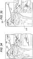
- FIG. 24illustrates the final knot assembly suture construct 60 of FIG. 23 .
- FIGS. 25-35illustrate various steps of a method of arthroscopic repair using the meniscal cinch assembly 100 of the present invention.
- meniscal cinch assembly 100comprises a push rod assembly 110 (a trocar assembly 110) ( FIGS. 1-4 ), a suture implant construct 60 ( FIG. 9 ) fully seated onto the trocar assembly 110, and a delivery system 120 ( FIG. 11 ) for releasing and advancing implants of the suture implant construct 60 onto the exterior surface of a meniscus.
- trocar assembly 110 of the meniscal cinch assembly 100comprises a first trocar 10 in communication with a second trocar 20, the first and second trocars being designed to carry onto their external surfaces a first implant 40 (on the first trocar 10) and a second implant 50 (on the second trocar 20).
- FIG. 2illustrates depth stop 30 of the meniscal cinch assembly 100 comprising an upper slot 31, a lower slot 33, and a depth slot 35.
- Depth stop 30is designed to ensure appropriate release of the first and second implants 40, 50 into the meniscal tissue to be repaired (i.e., it limits the protrusion distance of the implant loaded trocar beyond the tip of the meniscal cinch cannula 100). Uncontrolled advancement of the implants into the damaged meniscal tissue may have unwanted consequences and may require additional repair steps.
- the second trocar 20is slid into the bottom hole of the depth stop 30 to machined groove 37 ( FIGS. 1 and 3 ) and snapped upward into the upper slot 31 of depth stop 30 to secure (see detail A of FIG. 4 ).
- the first trocar 10is slid into the bottom hole of the depth stop 30 until the handle mates with depth stop 30, as shown in FIG. 3 .
- FIGS. 6-10illustrate the suture construct 60 with connected first and second implants 40, 50 mounted on the first and second trocars 10, 20.
- the suture constructis assembled to the first and second trocars 10, 20 by sliding the long lead first implant 40 onto the first trocar 10, oriented and fully seated as shown in FIG. 7 (detail B). Without twisting the suture leads, short lead second implant 50 is slid onto the second trocar 20, oriented and fully seated as shown in FIG. 8 (detail C). With implants 40, 50 fully seated, ensure that slight suture slack between implants is acceptable, and also that the suture is laying against the trocars 10, 20 and the free end is not twisted around the suture construct, trocars or depth stop. The sliding knot must not be tensioned tight and located beyond the second implant.
- the construct 60is loose and tangle free before insertion.
- the implants 40, 50may be formed of PEEK or similar material and flexible strand 45 may be a suture and/or may comprise a bioabsorbable material, such as PLLA or one of the other polylactides, for example, and/or may be formed of twisted fibers having strands of a contrasting color added to the braided threads, to make the suture more visible during surgical procedures.
- strand 45may contain strands of a high strength suture material, such as Arthrex FiberWire ® suture disclosed in U.S. Pat. No. 6,716,234 .
- FIGS. 11-13The subassembly 110 of FIG. 10 is slid into appropriate holes 122 and ratchet grooves 124 of delivery device 120 ( FIG. 11 ) to obtain the meniscal cinch assembly 100 shown in FIGS. 12 and 13 .
- the subassembly 110is slid in until reaching depth stop 30.
- the tabs 38 of depth stop 30are squeezed together to advance the subassembly 110 to first ratchet tooth 128 ( FIG. 12 ).
- the tabs 38 of the stop depth 20are then released to secure the subassembly in the docked position.
- the first implant 40makes contact with the mensical tissue and, as a result, is released from the exterior surface of the first trocar 10.
- the first implant 40flips about 90-degrees and becomes secured on the exterior surface of the meniscus.
- the first trocar 10is then fully removed from the cannula.
- the operationis repeated with the second trocar 20 loaded with the second implant 50. Once the second implant 50 is released, the implant flips about 90-degrees and becomes secured on the exterior surface of the meniscus adjacent to the first implant 40.
- the meniscal cinch assemblyis then removed from the knee.
- FIGS. 14-17illustrates various views of implant 40 used with the meniscal cinch assembly 100 of the present invention.
- the implanthas a cannulation 42 in a direction about parallel to the longitudinal axis 43 of the implant and through which suture is inserted.
- the implantalso has opposing end faces 46, 48 ( FIG. 14 ) that are about perpendicular to the longitudinal axis of the implant.
- FIGS. 18-24illustrate various steps in the formation of a knot assembly suture construct 60 (comprising first and second implants 40, 50 attached by a strand 45) used with the meniscal cinch assembly 100 of the present invention.
- FIG. 24illustrates the final knot assembly suture construct 60 of FIG. 23 .
- Knot assembly suture construct 60withstands about 45N tensile pull test.
- a single braided implant constructis threaded onto prebraided long suture 45 (for example, an 18 inch suture) oriented as shown in FIG. 18 .
- the right tail leadis wrapped under the post, as shown in FIG. 19 .
- the tail leadis wrapped over the post and passed through opening exiting out under the right lead, as shown in FIG. 20 .
- the tailis wrapped around the right lead and post, as shown in FIG. 21 .
- the tailis wrapped around the post back toward opening and over cross lead, as illustrated in FIG. 22 .
- the tailis tucked in the second opening, exiting out under the right lead ( FIG. 23 ).
- the sliding knotis tensioned down to the desired dimension ( FIG. 24 ) to obtain the final construct 60.
- FIGS. 25-35illustrate various steps of a method of arthroscopic repair using the meniscal cinch assembly 100 of the present invention.
- the methodsdistribute suture pressure to tissue, reduce tissue cut, and allow for accelerated tissue healing that is achieved with minimal knot tying.
- the inventionwill be described below with reference to an arthroscopic meniscal knee joint repair.
- the inventionis not limited to this exemplary embodiment and has applicability to any reattachment of tissue to tissue (for example, reattachment of labral tissue (cartilage) to the glenoid).
- the repair 200( FIG. 35 ) according to an exemplary cinch stitching technique includes the following steps:
- the meniscal cinch assembly 100 of the present inventionallows surgeons to repair meniscus tears with an all-inside arhtroscopic technique eliminating the need for accessory incisions required for traditional inside/out techniques that often result in additional morbidity. Based on the tear pattern and location, the meniscal cinch assembly 100 of the present invention gives surgeons the option of horizontal or vertical mattress repair with a flexible strand (such as a #2 FiberWire suture, for example). The present sliding knot and the FiberWire properties create a secure, low profile knot that can be countersunk into the meniscus. Depending on the exact location and pattern, posterior horn tears can be repaired through standard ipsilateral or contralateral arthroscopy portals. The meniscal cinch assembly 100 may be placed through the contralateral or accessory contralateral portal for tears involving the body of the meniscus.
Landscapes
- Health & Medical Sciences (AREA)
- Surgery (AREA)
- Life Sciences & Earth Sciences (AREA)
- Medical Informatics (AREA)
- Nuclear Medicine, Radiotherapy & Molecular Imaging (AREA)
- Engineering & Computer Science (AREA)
- Biomedical Technology (AREA)
- Heart & Thoracic Surgery (AREA)
- Rheumatology (AREA)
- Molecular Biology (AREA)
- Animal Behavior & Ethology (AREA)
- General Health & Medical Sciences (AREA)
- Public Health (AREA)
- Veterinary Medicine (AREA)
- Surgical Instruments (AREA)
- Prostheses (AREA)
Description
- The present invention relates to a system for arthroscopic surgery and, more specifically, to a system for repairing tears in tissue, such as meniscal tissue.
- Tissue repair requires the surgeon to pass suture material through selected tissue, form a plurality of surgical knots extracorporeally and then move the knots into position adjacent the desired tissue to be sutured. In such procedures, the surgeon must manually tie the knots on the suture strands after the suture is threaded through the selected tissues to be sutured. Knot tying during surgery, particularly arthroscopic surgery, is tedious and time-consuming. There is also a tendency for the knots to deform or collapse as the surgeon manually forces the knots down into the proper position. US patent application publication number
US 2006/0030885 discloses an apparatus and a method for heart valve repair. US patent application publication numberUS 2007/0027476 discloses a system and a method for all-inside suture fixation for implant attachment and soft tissue repair. International patent publicationWO 03/077772 US 2003/236535 discloses an apparatus for ligating/suturing living tissues and a system for resecting/suturing living tissues. US2007/027476 A1 discloses a system for repairing a meniscus including a suture that includes a first cannulated anchor, a second cannulated anchor, a flexible portion connecting the first anchor and the second anchor, and a self-locking slide knot.- Accordingly, a need exists for an improved system for repairing tears in soft tissue (such as the meniscus) which does not require multiple suture knots.
- The present invention is defined in accordance with appended
claim 1. The invention provides a system for repairing tears in meniscal tissue, by employing cinch stitching. More specifically, the present invention provides an apparatus for meniscal repair using a suture implant construct. The suture implant construct comprises a first and second implant which are connected to each other via a length of suture. The implants are designed to be loaded on external surfaces of the first and second trocars. - Other features and advantages of the present invention will become apparent from the following description of the invention, which refers to the accompanying drawings.
FIG. 1 illustrates a side view of a first and second trocars of a meniscal cinch assembly according to an embodiment of the present invention;FIG. 2 is a side view of the depth stop to be assembled to the first and second trocars ofFIG. 1 ;FIG. 3 illustrates a side view of first and second trocars ofFIG. 1 (with a depth stop attached);FIG. 4 illustrates an enlarged view of the detail A ofFIG. 3 ;FIG. 5 illustrates a perspective view of the meniscal cinch assembly of the present invention;FIG. 6 illustrates a top view of the meniscal cinch assembly of the present invention with a first and second implant seated;FIG. 7 illustrates a side view of the first implant of the meniscal cinch assembly ofFIG. 6 ;FIG. 8 illustrates a side view of the second implant of the meniscal cinch assembly ofFIG. 6 ;FIG. 9 illustrates a side view of the first and second implants of the meniscal cinch assembly ofFIG. 6 , connected by a flexible strand;FIG. 10 illustrates a side view of the meniscal cinch assembly of the present invention with a first and second implant seated;FIG. 11 illustrates a perspective view of the first and second trocars of the meniscal cinch assembly of the present invention, prior to sliding the trocar/suture assembly within the delivery hand piece;FIG. 12 illustrates another perspective view of the meniscal cinch assembly of the present invention;FIG. 13 illustrates another perspective view of the meniscal cinch assembly of the present invention;FIG. 14 illustrates a perspective view of an implant used with the meniscal cinch assembly of the present invention;FIG. 15 illustrates a side view of the implant ofFIG. 14 ;FIG. 16 illustrates a lateral view of the implant ofFIG. 14 ;FIG. 17 illustrates a bottom view of the implant ofFIG. 14 ;FIGS. 18-24 illustrates various steps in the formation of a knot assembly suture construct used with the meniscal cinch assembly of the present invention; andFIGS. 25-35 illustrate various steps of a method of arthroscopic repair using the meniscal cinch assembly of the present invention.- In the following detailed description, reference is made to various specific embodiments in which the invention may be practiced. These embodiments are described with sufficient detail to enable those skilled in the art to practice the invention, and it is to be understood that other embodiments may be employed, and that structural and logical changes may be made .
- The present disclosure provides a system for repairing tears in soft tissue (such as the meniscus) employing cinch stitching. In particular embodiments, the present invention provides a meniscal cinch assembly comprising first and second trocars, a depth stop adapted to securely engage one of the trocars, and a suture implant construct configured to be loaded onto external surfaces of the first and second trocars of the meniscal cinch assembly.
- The suture implant construct of the present invention comprises a first and second implant which are connected to each other via a length of suture. The implants are designed to be loaded on external surfaces of the first and second trocars. Each implant has a through-hole running in a direction parallel to the longitudinal axis of the implant and through which suture is inserted. As detailed below, the implants are configured with opposing planar end faces that are perpendicular to the longitudinal axis of the implant.
- The present disclosure also provides methods for soft tissue fixation (such as mensical repair, for example) by cinch stitching. According to an exemplary method, the method comprises the steps of: (i) providing a meniscal cinch assembly comprising first and second trocars, a depth stop adapted to securely engage one of the trocars, and a suture implant construct having first and second implants loaded on the external surface of the first and second trocars; and (ii) passing at least one of the first and second implants through tissue to be repaired (for example, labral tissue of the glenoid or meniscal knee tissue).
- Referring now to the drawings, where like elements are designated by like reference numerals,
FIGS. 1-13 illustrate ameniscal cinch assembly 100 of the present invention (comprising first andsecond trocars depth stop 30; and first andsecond implants 40, 50).FIGS. 14-17 illustrate implant 40 used with themeniscal cinch assembly 100 of the present invention.FIGS. 18-23 illustrate various steps in the formation of a knot assembly suture construct 60 (comprising first andsecond implants meniscal cinch assembly 100 of the present invention.FIG. 24 illustrates the final knotassembly suture construct 60 ofFIG. 23 .FIGS. 25-35 illustrate various steps of a method of arthroscopic repair using themeniscal cinch assembly 100 of the present invention. - Reference is now made to
FIGS. 1-13 which illustratemeniscal cinch assembly 100 of the present invention including an actuating mechanism configured to operate a suture implant construct. As shown in the drawings, meniscal cinch assembly 100 (FIGS. 5 ,12 and 13 ) comprises a push rod assembly 110 (a trocar assembly 110) (FIGS. 1-4 ), a suture implant construct 60 (FIG. 9 ) fully seated onto thetrocar assembly 110, and a delivery system 120 (FIG. 11 ) for releasing and advancing implants of the suture implant construct 60 onto the exterior surface of a meniscus. - As shown in
FIGS. 1-4 ,trocar assembly 110 of themeniscal cinch assembly 100 comprises afirst trocar 10 in communication with asecond trocar 20, the first and second trocars being designed to carry onto their external surfaces a first implant 40 (on the first trocar 10) and a second implant 50 (on the second trocar 20). FIG. 2 illustratesdepth stop 30 of themeniscal cinch assembly 100 comprising anupper slot 31, alower slot 33, and adepth slot 35.Depth stop 30 is designed to ensure appropriate release of the first andsecond implants - In use, the
second trocar 20 is slid into the bottom hole of the depth stop 30 to machined groove 37 (FIGS. 1 and 3 ) and snapped upward into theupper slot 31 ofdepth stop 30 to secure (see detail A ofFIG. 4 ). Thefirst trocar 10 is slid into the bottom hole of the depth stop 30 until the handle mates withdepth stop 30, as shown inFIG. 3 . FIGS. 6-10 illustrate thesuture construct 60 with connected first andsecond implants second trocars second trocars first implant 40 onto thefirst trocar 10, oriented and fully seated as shown inFIG. 7 (detail B). Without twisting the suture leads, short leadsecond implant 50 is slid onto thesecond trocar 20, oriented and fully seated as shown inFIG. 8 (detail C). Withimplants trocars construct 60 is loose and tangle free before insertion.- The
implants flexible strand 45 may be a suture and/or may comprise a bioabsorbable material, such as PLLA or one of the other polylactides, for example, and/or may be formed of twisted fibers having strands of a contrasting color added to the braided threads, to make the suture more visible during surgical procedures. In exemplary embodiments,strand 45 may contain strands of a high strength suture material, such as Arthrex FiberWire® suture disclosed inU.S. Pat. No. 6,716,234 . - Reference is made to
FIGS. 11-13 . Thesubassembly 110 ofFIG. 10 is slid intoappropriate holes 122 and ratchetgrooves 124 of delivery device 120 (FIG. 11 ) to obtain themeniscal cinch assembly 100 shown inFIGS. 12 and 13 . Thesubassembly 110 is slid in until reachingdepth stop 30. Thetabs 38 ofdepth stop 30 are squeezed together to advance thesubassembly 110 to first ratchet tooth 128 (FIG. 12 ). Thetabs 38 of thestop depth 20 are then released to secure the subassembly in the docked position. - As detailed below, when the first trocar is pulled from the meniscus, the
first implant 40 makes contact with the mensical tissue and, as a result, is released from the exterior surface of thefirst trocar 10. As thefirst implant 40 is released from the exterior surface of thefirst trocar 10, it flips about 90-degrees and becomes secured on the exterior surface of the meniscus. Thefirst trocar 10 is then fully removed from the cannula. The operation is repeated with thesecond trocar 20 loaded with thesecond implant 50. Once thesecond implant 50 is released, the implant flips about 90-degrees and becomes secured on the exterior surface of the meniscus adjacent to thefirst implant 40. The meniscal cinch assembly is then removed from the knee. FIGS. 14-17 illustrates various views ofimplant 40 used with themeniscal cinch assembly 100 of the present invention. As shown inFIG. 14 , for example, the implant has acannulation 42 in a direction about parallel to thelongitudinal axis 43 of the implant and through which suture is inserted. The implant also has opposing end faces 46, 48 (FIG. 14 ) that are about perpendicular to the longitudinal axis of the implant.FIGS. 18-24 illustrate various steps in the formation of a knot assembly suture construct 60 (comprising first andsecond implants meniscal cinch assembly 100 of the present invention.FIG. 24 illustrates the final knot assembly suture construct 60 ofFIG. 23 . Knot assembly suture construct 60 withstands about 45N tensile pull test.- In use, a single braided implant construct is threaded onto prebraided long suture 45 (for example, an 18 inch suture) oriented as shown in
FIG. 18 . The right tail lead is wrapped under the post, as shown inFIG. 19 . The tail lead is wrapped over the post and passed through opening exiting out under the right lead, as shown inFIG. 20 . The tail is wrapped around the right lead and post, as shown inFIG. 21 . The tail is wrapped around the post back toward opening and over cross lead, as illustrated inFIG. 22 . The tail is tucked in the second opening, exiting out under the right lead (FIG. 23 ). The sliding knot is tensioned down to the desired dimension (FIG. 24 ) to obtain thefinal construct 60. - Reference is now made to
FIGS. 25-35 which illustrate various steps of a method of arthroscopic repair using themeniscal cinch assembly 100 of the present invention. The methods distribute suture pressure to tissue, reduce tissue cut, and allow for accelerated tissue healing that is achieved with minimal knot tying. - For exemplary purposes only, the invention will be described below with reference to an arthroscopic meniscal knee joint repair. However, the invention is not limited to this exemplary embodiment and has applicability to any reattachment of tissue to tissue (for example, reattachment of labral tissue (cartilage) to the glenoid).
- The repair 200 (
FIG. 35 ) according to an exemplary cinch stitching technique includes the following steps: FIG. 25 : The meniscal cinch is designed to be used through a low arthroscopic portal, near the surface of thetibia 210. A measurement is taken to approximate the distance between the entry point of theimplant FIG. 26 : Thedepth stop 30 on the meniscal cinch handle is set to the distance measured above, by squeezing the tips together and sliding thedepth stop 30 forward. Thedepth stop 30 is set to a distance about equal to the measurement in the step ofFIG. 25 . Each line on the handle represents about 2mm.FIG. 27 : A cannula (for example, a shoehorn cannula) may be placed into the working portal before inserting themeniscal cinch device 100. Place the tip of the meniscal cinch cannula near the tear. The tip of the cannula may be used to reduce the tear prior to deployment of thefirst trocar 10. Alternatively, the tip of the first trocar may be advanced past the tip of the cannula to be used to reduce the tear. The trocar should not be pulled back into the cannula after it has been advanced as it could prematurely deploy the implant.FIG. 28 : The tip of the meniscal cinch cannula is placed in contact with, but does not pierce, the meniscus near the meniscal tear. Thefirst implant 40 is advanced through the meniscus by pushing thefirst trocar 10 forward until the trocar handle makes contact with thedepth stop 30 and the cannula rests on the surface of the meniscus. As thefirst trocar 10 is pulled from the meniscus, thefirst implant 40 makes contact with the meniscal tissue and as a result is released from the exterior surface of thefirst trocar 10. As thefirst implant 40 is released from the exterior surface of thefirst trocar 10, it flips about 90-degrees and becomes secured on the exterior surface of the meniscus.FIG. 29 : Thefirst trocar 10 is then removed from the cannula completely. A slight downward force on thefirst trocar 10 during removal ensures that it does not interfere with thesecond trocar 20.FIG. 30 : Push down on thesecond trocar 20, to release it from the holding position. Next, the tip of the cannula is moved to the second insertion point so that the tip of the cannula is in contact with, but does not pierce, the meniscus.FIGS. 31 and32 : Thesecond trocar 20 is advanced forward by pushing the trocar handle. Thesecond trocar 20 is advanced through the meniscus until the trocar handle makes contact with thedepth stop 30 and the cannula rests on the surface of the meniscus. Suture slack created by advancing thesecond trocar 20 may be reduced partially by gently tensioning external suture near the handle. Stop tensioning if resistance is felt.FIG. 33 : Thesecond trocar 20 is then fully removed from the cannula. While thesecond trocar 20 is being removed, thesecond implant 50 is released from the exterior surface of thesecond trocar 20. Thesecond implant 50 then flips 90-degrees and becomes secured on the exterior surface of the meniscus adjacent to thefirst implant 40. Themeniscal cinch assembly 100 is then removed from the joint. The external suture is tensioned to advance the knot to the meniscus.FIG. 34 : The external suture is threaded through the tip of asuture passing instrument 150 such as a knot pusher-suture cutter instrument 150. The knot is pushed while pulling tension on the free end of suture. The knot is advanced until it is countersunk into the meniscal tissue.FIG. 35 : The trigger on the handle of the knot pusher-suture cutter 150 is then advanced to cut the suture (the suture is pulled in line with thecutter 150 and rotation of handle is avoided while suture is cut). The cutter is removed to obtain the final construct 200 (with the implants in a horizontal orientation). Alternatively, the implants may be inserted in a vertical orientation (a vertical mattress stitch).- The
meniscal cinch assembly 100 of the present invention allows surgeons to repair meniscus tears with an all-inside arhtroscopic technique eliminating the need for accessory incisions required for traditional inside/out techniques that often result in additional morbidity. Based on the tear pattern and location, themeniscal cinch assembly 100 of the present invention gives surgeons the option of horizontal or vertical mattress repair with a flexible strand (such as a #2 FiberWire suture, for example). The present sliding knot and the FiberWire properties create a secure, low profile knot that can be countersunk into the meniscus. Depending on the exact location and pattern, posterior horn tears can be repaired through standard ipsilateral or contralateral arthroscopy portals. Themeniscal cinch assembly 100 may be placed through the contralateral or accessory contralateral portal for tears involving the body of the meniscus. - Although the present invention has been described in connection with preferred embodiments, many modifications and variations will become apparent to those skilled in the art. While preferred embodiments of the invention have been described and illustrated above, it should be understood that these are exemplary of the invention and are not to be considered as limiting. Accordingly, it is not intended that the present invention be limited to the illustrated embodiments, but only by the appended claims.
Claims (8)
- A surgical system (100) for repairing tears in soft tissue, comprising:an apparatus for meniscal repair comprising a trocar assembly (110) having a pair of substantially parallel first and second trocars (10, 20);a suture implant construct (60) fully seated onto the trocar assembly (110), the suture implant construct (60) comprising a first anchoring member (40) and a second anchoring member (50), the first anchoring member (40) being connected to the second anchoring member (50) by a single flexible strand (45); anda driver assembly (120) for advancing the first and second trocars (10, 20) through the soft tissue to be repaired;wherein:the first anchoring member (40) is mounted on an external surface of the first trocar (10) and the connection of the single flexible strand (45) to the first anchoring member (40) is configured such that when the first anchoring member (40) is released from the first trocar (10), the first anchoring member (40) flips about 90 degrees to become secured on an exterior surface of the soft tissue;the second anchoring member (50) is mounted on an external surface of the second trocar (20) and the connection of the single flexible strand (45) to the second anchoring member (50) is configured such that when the second anchoring member (50) is released from the second trocar (20), the second anchoring member flips about 90 degrees to become secured on the exterior surface of the soft tissue; andthe single flexible strand (45) connecting the first and second anchoring members (40, 50) includes a sliding knot (60) for tensioning and removing slack in the single flexible strand (45) after the first and second anchoring members (40, 50) are secured on the exterior surface of the tissue by tensioning the single flexible strand (45) to advance the knot in the soft tissue, and wherein each of the first and second anchoring members (40, 50) has a cannulation (42) in a direction about parallel to a longitudinal axis (43) of each of the first and second anchoring members (40, 50) and through which the single flexible strand (45) connecting the first and second anchoring members (40, 50) is inserted.
- The system of claim 1, wherein the driver assembly (120) comprises:an actuating mechanism comprising a body having a proximal end and a distal end, a handle attached to the proximal end, and an elongated shaft extending from the distal end of the body; andwherein the first trocar (10) and second trocar (20) are positioned within the longitudinal pathway of the body of the actuating mechanism.
- The system of claim 2, wherein the first anchoring device (40) is configured to be deployed into the soft tissue to be repaired in response to operation of the actuating mechanism.
- The system of claim 2, wherein the second anchoring device (50) is configured to be deployed into the soft tissue to be repaired in response to operation of the actuating mechanism.
- The system of claim 2, wherein the elongated shaft of the actuating mechanism is provided with a bent section at its most distal end.
- The system of claim 1, wherein each of the first and second anchoring members (40, 50) is an implant having an elongated cylindrical body with the cannulation (42) having a diameter about equal to the diameter of each of the first and second trocars (10, 20), to allow mounting of the cylindrical body on the first and second trocars (10, 20).
- The system of claim 1, wherein the single flexible strand (45) is a suture strand.
- The system of claim 1, wherein the single flexible strand (45) is an Arthrex FiberWire® suture.
Applications Claiming Priority (1)
| Application Number | Priority Date | Filing Date | Title |
|---|---|---|---|
| US3364408P | 2008-03-04 | 2008-03-04 |
Publications (2)
| Publication Number | Publication Date |
|---|---|
| EP2098172A1 EP2098172A1 (en) | 2009-09-09 |
| EP2098172B1true EP2098172B1 (en) | 2017-02-22 |
Family
ID=40671192
Family Applications (1)
| Application Number | Title | Priority Date | Filing Date |
|---|---|---|---|
| EP09250604.7AActiveEP2098172B1 (en) | 2008-03-04 | 2009-03-03 | System for meniscal repair using suture implant cinch construct |
Country Status (2)
| Country | Link |
|---|---|
| US (4) | US8961538B2 (en) |
| EP (1) | EP2098172B1 (en) |
Families Citing this family (111)
| Publication number | Priority date | Publication date | Assignee | Title |
|---|---|---|---|---|
| US7887551B2 (en) | 1999-12-02 | 2011-02-15 | Smith & Nephew, Inc. | Soft tissue attachment and repair |
| US6520964B2 (en) | 2000-05-01 | 2003-02-18 | Std Manufacturing, Inc. | System and method for joint resurface repair |
| US6610067B2 (en) | 2000-05-01 | 2003-08-26 | Arthrosurface, Incorporated | System and method for joint resurface repair |
| US8388624B2 (en) | 2003-02-24 | 2013-03-05 | Arthrosurface Incorporated | Trochlear resurfacing system and method |
| WO2006004885A2 (en) | 2004-06-28 | 2006-01-12 | Arthrosurface, Inc. | System for articular surface replacement |
| US7749250B2 (en) | 2006-02-03 | 2010-07-06 | Biomet Sports Medicine, Llc | Soft tissue repair assembly and associated method |
| US8137382B2 (en) | 2004-11-05 | 2012-03-20 | Biomet Sports Medicine, Llc | Method and apparatus for coupling anatomical features |
| US8361113B2 (en) | 2006-02-03 | 2013-01-29 | Biomet Sports Medicine, Llc | Method and apparatus for coupling soft tissue to a bone |
| US8840645B2 (en) | 2004-11-05 | 2014-09-23 | Biomet Sports Medicine, Llc | Method and apparatus for coupling soft tissue to a bone |
| US8128658B2 (en) | 2004-11-05 | 2012-03-06 | Biomet Sports Medicine, Llc | Method and apparatus for coupling soft tissue to bone |
| US8118836B2 (en) | 2004-11-05 | 2012-02-21 | Biomet Sports Medicine, Llc | Method and apparatus for coupling soft tissue to a bone |
| US7909851B2 (en) | 2006-02-03 | 2011-03-22 | Biomet Sports Medicine, Llc | Soft tissue repair device and associated methods |
| US9017381B2 (en) | 2007-04-10 | 2015-04-28 | Biomet Sports Medicine, Llc | Adjustable knotless loops |
| US8298262B2 (en) | 2006-02-03 | 2012-10-30 | Biomet Sports Medicine, Llc | Method for tissue fixation |
| US7857830B2 (en) | 2006-02-03 | 2010-12-28 | Biomet Sports Medicine, Llc | Soft tissue repair and conduit device |
| US7905904B2 (en) | 2006-02-03 | 2011-03-15 | Biomet Sports Medicine, Llc | Soft tissue repair device and associated methods |
| US8303604B2 (en) | 2004-11-05 | 2012-11-06 | Biomet Sports Medicine, Llc | Soft tissue repair device and method |
| US8088130B2 (en) | 2006-02-03 | 2012-01-03 | Biomet Sports Medicine, Llc | Method and apparatus for coupling soft tissue to a bone |
| US7658751B2 (en) | 2006-09-29 | 2010-02-09 | Biomet Sports Medicine, Llc | Method for implanting soft tissue |
| US9801708B2 (en) | 2004-11-05 | 2017-10-31 | Biomet Sports Medicine, Llc | Method and apparatus for coupling soft tissue to a bone |
| US8998949B2 (en) | 2004-11-09 | 2015-04-07 | Biomet Sports Medicine, Llc | Soft tissue conduit device |
| JP5030797B2 (en) | 2005-02-07 | 2012-09-19 | アイビー スポーツ メディシン、エルエルシー | System and method for fully internal suture fixation of implant placement and soft tissue repair |
| US8128640B2 (en) | 2005-02-07 | 2012-03-06 | Ivy Sports Medicine LLC | System and method for all-inside suture fixation for implant attachment and soft tissue repair |
| US11311287B2 (en) | 2006-02-03 | 2022-04-26 | Biomet Sports Medicine, Llc | Method for tissue fixation |
| US9149267B2 (en) | 2006-02-03 | 2015-10-06 | Biomet Sports Medicine, Llc | Method and apparatus for coupling soft tissue to a bone |
| US8968364B2 (en) | 2006-02-03 | 2015-03-03 | Biomet Sports Medicine, Llc | Method and apparatus for fixation of an ACL graft |
| US8652172B2 (en) | 2006-02-03 | 2014-02-18 | Biomet Sports Medicine, Llc | Flexible anchors for tissue fixation |
| US11259792B2 (en) | 2006-02-03 | 2022-03-01 | Biomet Sports Medicine, Llc | Method and apparatus for coupling anatomical features |
| US8562645B2 (en) | 2006-09-29 | 2013-10-22 | Biomet Sports Medicine, Llc | Method and apparatus for forming a self-locking adjustable loop |
| US8506597B2 (en) | 2011-10-25 | 2013-08-13 | Biomet Sports Medicine, Llc | Method and apparatus for interosseous membrane reconstruction |
| US9078644B2 (en) | 2006-09-29 | 2015-07-14 | Biomet Sports Medicine, Llc | Fracture fixation device |
| US8771352B2 (en) | 2011-05-17 | 2014-07-08 | Biomet Sports Medicine, Llc | Method and apparatus for tibial fixation of an ACL graft |
| US8652171B2 (en) | 2006-02-03 | 2014-02-18 | Biomet Sports Medicine, Llc | Method and apparatus for soft tissue fixation |
| US8251998B2 (en) | 2006-08-16 | 2012-08-28 | Biomet Sports Medicine, Llc | Chondral defect repair |
| US8574235B2 (en) | 2006-02-03 | 2013-11-05 | Biomet Sports Medicine, Llc | Method for trochanteric reattachment |
| US9468433B2 (en) | 2006-02-03 | 2016-10-18 | Biomet Sports Medicine, Llc | Method and apparatus for forming a self-locking adjustable loop |
| US8801783B2 (en) | 2006-09-29 | 2014-08-12 | Biomet Sports Medicine, Llc | Prosthetic ligament system for knee joint |
| US8562647B2 (en) | 2006-09-29 | 2013-10-22 | Biomet Sports Medicine, Llc | Method and apparatus for securing soft tissue to bone |
| US8597327B2 (en) | 2006-02-03 | 2013-12-03 | Biomet Manufacturing, Llc | Method and apparatus for sternal closure |
| US10517587B2 (en) | 2006-02-03 | 2019-12-31 | Biomet Sports Medicine, Llc | Method and apparatus for forming a self-locking adjustable loop |
| US9538998B2 (en) | 2006-02-03 | 2017-01-10 | Biomet Sports Medicine, Llc | Method and apparatus for fracture fixation |
| US9271713B2 (en) | 2006-02-03 | 2016-03-01 | Biomet Sports Medicine, Llc | Method and apparatus for tensioning a suture |
| US11259794B2 (en) | 2006-09-29 | 2022-03-01 | Biomet Sports Medicine, Llc | Method for implanting soft tissue |
| US8500818B2 (en) | 2006-09-29 | 2013-08-06 | Biomet Manufacturing, Llc | Knee prosthesis assembly with ligament link |
| US9918826B2 (en) | 2006-09-29 | 2018-03-20 | Biomet Sports Medicine, Llc | Scaffold for spring ligament repair |
| US8672969B2 (en) | 2006-09-29 | 2014-03-18 | Biomet Sports Medicine, Llc | Fracture fixation device |
| US9358029B2 (en) | 2006-12-11 | 2016-06-07 | Arthrosurface Incorporated | Retrograde resection apparatus and method |
| EP2262448A4 (en) | 2008-03-03 | 2014-03-26 | Arthrosurface Inc | Bone resurfacing system and method |
| US12245759B2 (en) | 2008-08-22 | 2025-03-11 | Biomet Sports Medicine, Llc | Method and apparatus for coupling soft tissue to bone |
| US12419632B2 (en) | 2008-08-22 | 2025-09-23 | Biomet Sports Medicine, Llc | Method and apparatus for coupling anatomical features |
| CN103705280B (en) | 2008-11-26 | 2017-11-14 | 史密夫和内修有限公司 | Tissue repair device |
| US10945743B2 (en) | 2009-04-17 | 2021-03-16 | Arthrosurface Incorporated | Glenoid repair system and methods of use thereof |
| WO2010121250A1 (en) | 2009-04-17 | 2010-10-21 | Arthrosurface Incorporated | Glenoid resurfacing system and method |
| AU2010236182A1 (en) | 2009-04-17 | 2011-11-24 | Arthrosurface Incorporated | Glenoid resurfacing system and method |
| US8343227B2 (en) | 2009-05-28 | 2013-01-01 | Biomet Manufacturing Corp. | Knee prosthesis assembly with ligament link |
| US12096928B2 (en) | 2009-05-29 | 2024-09-24 | Biomet Sports Medicine, Llc | Method and apparatus for coupling soft tissue to a bone |
| US8828053B2 (en)* | 2009-07-24 | 2014-09-09 | Depuy Mitek, Llc | Methods and devices for repairing and anchoring damaged tissue |
| US8790369B2 (en)* | 2009-07-24 | 2014-07-29 | Depuy Mitek, Llc | Apparatus and method for repairing tissue |
| US8814903B2 (en)* | 2009-07-24 | 2014-08-26 | Depuy Mitek, Llc | Methods and devices for repairing meniscal tissue |
| WO2011057394A1 (en) | 2009-11-12 | 2011-05-19 | Anchor Orthopedics Xt, Inc. | Devices and methods for treating tissue defects |
| EP2542165A4 (en) | 2010-03-05 | 2015-10-07 | Arthrosurface Inc | Tibial resurfacing system and method |
| US9597064B2 (en) | 2010-04-27 | 2017-03-21 | DePuy Synthes Products, Inc. | Methods for approximating a tissue defect using an anchor assembly |
| US9451938B2 (en) | 2010-04-27 | 2016-09-27 | DePuy Synthes Products, Inc. | Insertion instrument for anchor assembly |
| US9743919B2 (en) | 2010-04-27 | 2017-08-29 | DePuy Synthes Products, Inc. | Stitch lock for attaching two or more structures |
| CA2797607A1 (en) | 2010-04-27 | 2011-11-03 | Synthes Usa, Llc | Anchor assembly including expandable anchor |
| US9066716B2 (en) | 2011-03-30 | 2015-06-30 | Arthrosurface Incorporated | Suture coil and suture sheath for tissue repair |
| US12329373B2 (en) | 2011-05-02 | 2025-06-17 | Biomet Sports Medicine, Llc | Method and apparatus for soft tissue fixation |
| US9198648B2 (en)* | 2011-06-20 | 2015-12-01 | Ethicon, Inc. | Method and device for approximating tissue |
| US9357991B2 (en) | 2011-11-03 | 2016-06-07 | Biomet Sports Medicine, Llc | Method and apparatus for stitching tendons |
| US9370350B2 (en) | 2011-11-10 | 2016-06-21 | Biomet Sports Medicine, Llc | Apparatus for coupling soft tissue to a bone |
| US9314241B2 (en) | 2011-11-10 | 2016-04-19 | Biomet Sports Medicine, Llc | Apparatus for coupling soft tissue to a bone |
| US9381013B2 (en) | 2011-11-10 | 2016-07-05 | Biomet Sports Medicine, Llc | Method for coupling soft tissue to a bone |
| EP2804565B1 (en) | 2011-12-22 | 2018-03-07 | Arthrosurface Incorporated | System for bone fixation |
| WO2013096855A1 (en)* | 2011-12-23 | 2013-06-27 | Arthrex, Inc. | Drive system for tissue repair |
| WO2014008126A1 (en) | 2012-07-03 | 2014-01-09 | Arthrosurface Incorporated | System and method for joint resurfacing and repair |
| US9517060B2 (en) | 2012-09-27 | 2016-12-13 | Ethicon, Inc. | Method and device for approximating tissue |
| US9757119B2 (en) | 2013-03-08 | 2017-09-12 | Biomet Sports Medicine, Llc | Visual aid for identifying suture limbs arthroscopically |
| US9918827B2 (en) | 2013-03-14 | 2018-03-20 | Biomet Sports Medicine, Llc | Scaffold for spring ligament repair |
| US9492200B2 (en) | 2013-04-16 | 2016-11-15 | Arthrosurface Incorporated | Suture system and method |
| US10136886B2 (en) | 2013-12-20 | 2018-11-27 | Biomet Sports Medicine, Llc | Knotless soft tissue devices and techniques |
| US9993240B2 (en) | 2014-02-12 | 2018-06-12 | Roy H. Trawick | Meniscal repair device |
| US11607319B2 (en) | 2014-03-07 | 2023-03-21 | Arthrosurface Incorporated | System and method for repairing articular surfaces |
| US9931219B2 (en) | 2014-03-07 | 2018-04-03 | Arthrosurface Incorporated | Implant and anchor assembly |
| US10624748B2 (en) | 2014-03-07 | 2020-04-21 | Arthrosurface Incorporated | System and method for repairing articular surfaces |
| US9615822B2 (en) | 2014-05-30 | 2017-04-11 | Biomet Sports Medicine, Llc | Insertion tools and method for soft anchor |
| US9700291B2 (en) | 2014-06-03 | 2017-07-11 | Biomet Sports Medicine, Llc | Capsule retractor |
| US10039543B2 (en) | 2014-08-22 | 2018-08-07 | Biomet Sports Medicine, Llc | Non-sliding soft anchor |
| US10568616B2 (en) | 2014-12-17 | 2020-02-25 | Howmedica Osteonics Corp. | Instruments and methods of soft tissue fixation |
| US9955980B2 (en) | 2015-02-24 | 2018-05-01 | Biomet Sports Medicine, Llc | Anatomic soft tissue repair |
| US9974534B2 (en) | 2015-03-31 | 2018-05-22 | Biomet Sports Medicine, Llc | Suture anchor with soft anchor of electrospun fibers |
| US10463360B2 (en)* | 2015-07-17 | 2019-11-05 | Suturegard Medical, Inc. | Suture locks |
| EP3383281B1 (en) | 2015-12-04 | 2024-01-24 | Crossroads Extremity Systems, LLC | Devices for anchoring tissue |
| US10390814B2 (en) | 2016-04-20 | 2019-08-27 | Medos International Sarl | Meniscal repair devices, systems, and methods |
| US10932769B2 (en) | 2016-05-26 | 2021-03-02 | Ivy Sports Medicine, Llc | System and method for all-inside suture fixation for implant attachment and soft tissue repair |
| US10307154B2 (en) | 2016-09-27 | 2019-06-04 | Arthrex, Inc. | Circular suture constructs and methods for use |
| US10758224B2 (en) | 2017-03-27 | 2020-09-01 | Trimed, Incorporated | System and method controlling a relationship between first and second bodies on a person |
| US10799231B2 (en) | 2018-01-08 | 2020-10-13 | Arthrex, Inc. | Suture-implant construct and method of deploying the same |
| US11006944B2 (en) | 2017-07-07 | 2021-05-18 | Arthrex, Inc. | Surgical device and methods of delivering implants |
| US10675015B2 (en)* | 2017-07-12 | 2020-06-09 | Ethicon, Inc. | Systems, devices and methods for delivering transfascial suture implants for securing surgical mesh to tissue |
| US11160663B2 (en) | 2017-08-04 | 2021-11-02 | Arthrosurface Incorporated | Multicomponent articular surface implant |
| CA3086956A1 (en) | 2018-01-02 | 2019-07-11 | Cartiheal (2009) Ltd. | Implantation tool and protocol for optimized solid substrates promoting cell and tissue growth |
| USD902405S1 (en) | 2018-02-22 | 2020-11-17 | Stryker Corporation | Self-punching bone anchor inserter |
| WO2020186099A1 (en) | 2019-03-12 | 2020-09-17 | Arthrosurface Incorporated | Humeral and glenoid articular surface implant systems and methods |
| US11064995B2 (en) | 2019-05-02 | 2021-07-20 | Arthrex, Inc. | Surgical device with trigger operated needle |
| CN111388040B (en)* | 2020-03-25 | 2021-04-09 | 李晋 | Half-moon plate sewing crochet hook for orthopedic operation |
| EP4280973A4 (en)* | 2021-01-22 | 2025-02-12 | Paragon 28, Inc. | SOFT TISSUE IMPLANTS, INSTRUMENTATION AND METHODS |
| US12433581B2 (en) | 2021-08-23 | 2025-10-07 | Arthrex, Inc. | Tensionable interconnected anchors with double punch inserter |
| CN114668437B (en)* | 2022-05-31 | 2022-08-26 | 杭州锐健马斯汀医疗器材有限公司 | Suturing device |
| CN114699124B (en)* | 2022-06-07 | 2022-09-27 | 北京天星博迈迪医疗器械有限公司 | Rapid tissue suture implant and preparation method thereof |
| TWI852580B (en)* | 2023-05-24 | 2024-08-11 | 捷立康生物科技股份有限公司 | Surgical wires, their uses and methods of manufacture |
| CN116421241B (en)* | 2023-06-08 | 2023-08-22 | 北京万洁天元医疗器械股份有限公司 | Meniscus injury repair device |
Family Cites Families (36)
| Publication number | Priority date | Publication date | Assignee | Title |
|---|---|---|---|---|
| US3845772A (en) | 1973-09-17 | 1974-11-05 | D Smith | Retention suture device and method |
| US4235238A (en) | 1978-05-11 | 1980-11-25 | Olympus Optical Co., Ltd. | Apparatus for suturing coeliac tissues |
| US5417691A (en) | 1982-05-20 | 1995-05-23 | Hayhurst; John O. | Apparatus and method for manipulating and anchoring tissue |
| US6656182B1 (en) | 1982-05-20 | 2003-12-02 | John O. Hayhurst | Tissue manipulation |
| US5224946A (en)* | 1990-07-02 | 1993-07-06 | American Cyanamid Company | Bone anchor and method of anchoring a suture to a bone |
| US5258016A (en)* | 1990-07-13 | 1993-11-02 | American Cyanamid Company | Suture anchor and driver assembly |
| US5814073A (en)* | 1996-12-13 | 1998-09-29 | Bonutti; Peter M. | Method and apparatus for positioning a suture anchor |
| US5466243A (en)* | 1994-02-17 | 1995-11-14 | Arthrex, Inc. | Method and apparatus for installing a suture anchor through a hollow cannulated grasper |
| US5591207A (en)* | 1995-03-30 | 1997-01-07 | Linvatec Corporation | Driving system for inserting threaded suture anchors |
| US5697931A (en)* | 1995-06-14 | 1997-12-16 | Incont, Inc. | Apparatus and method for laparoscopic urethopexy |
| US5782862A (en)* | 1996-07-01 | 1998-07-21 | Bonutti; Peter M. | Suture anchor inserter assembly and method |
| US5948002A (en)* | 1996-11-15 | 1999-09-07 | Bonutti; Peter M. | Apparatus and method for use in positioning a suture anchor |
| US6554852B1 (en)* | 1999-08-25 | 2003-04-29 | Michael A. Oberlander | Multi-anchor suture |
| US6626930B1 (en)* | 1999-10-21 | 2003-09-30 | Edwards Lifesciences Corporation | Minimally invasive mitral valve repair method and apparatus |
| US7153312B1 (en)* | 1999-12-02 | 2006-12-26 | Smith & Nephew Inc. | Closure device and method for tissue repair |
| US7887551B2 (en)* | 1999-12-02 | 2011-02-15 | Smith & Nephew, Inc. | Soft tissue attachment and repair |
| US6635073B2 (en)* | 2000-05-03 | 2003-10-21 | Peter M. Bonutti | Method of securing body tissue |
| US6500184B1 (en)* | 2001-01-31 | 2002-12-31 | Yung C. Chan | Suturing apparatus and method of suturing |
| US6716234B2 (en) | 2001-09-13 | 2004-04-06 | Arthrex, Inc. | High strength suture material |
| CA2477220C (en) | 2002-03-14 | 2007-11-06 | Jeffrey E. Yeung | Suture anchor and approximating device |
| US8105342B2 (en) | 2002-05-08 | 2012-01-31 | Apollo Endosurgery, Inc. | Apparatus for ligating/suturing living tissues and system for resecting/suturing living tissues |
| US7087064B1 (en) | 2002-10-15 | 2006-08-08 | Advanced Cardiovascular Systems, Inc. | Apparatuses and methods for heart valve repair |
| US9314235B2 (en)* | 2003-02-05 | 2016-04-19 | Smith & Nephew, Inc. | Tissue anchor and insertion tool |
| JP4145200B2 (en) | 2003-06-06 | 2008-09-03 | オリンパス株式会社 | Suture device |
| US7909851B2 (en)* | 2006-02-03 | 2011-03-22 | Biomet Sports Medicine, Llc | Soft tissue repair device and associated methods |
| US7905904B2 (en)* | 2006-02-03 | 2011-03-15 | Biomet Sports Medicine, Llc | Soft tissue repair device and associated methods |
| US8128640B2 (en)* | 2005-02-07 | 2012-03-06 | Ivy Sports Medicine LLC | System and method for all-inside suture fixation for implant attachment and soft tissue repair |
| JP5030797B2 (en)* | 2005-02-07 | 2012-09-19 | アイビー スポーツ メディシン、エルエルシー | System and method for fully internal suture fixation of implant placement and soft tissue repair |
| US8702718B2 (en)* | 2005-04-29 | 2014-04-22 | Jmea Corporation | Implantation system for tissue repair |
| US7909836B2 (en)* | 2005-05-20 | 2011-03-22 | Neotract, Inc. | Multi-actuating trigger anchor delivery system |
| US7875041B2 (en)* | 2005-09-28 | 2011-01-25 | Olympus Medical Systems Corp. | Suturing method for penetrating hole |
| US8702753B2 (en)* | 2005-09-28 | 2014-04-22 | Olympus Medical Systems Corp. | Method for suturing perforation and suture instrument |
| US20080065120A1 (en)* | 2005-10-31 | 2008-03-13 | Zannis Anthony D | Surgical instrument, kit and method for creating mattress-type stitches |
| US20070100350A1 (en)* | 2005-10-31 | 2007-05-03 | Deffenbaugh Daren L | Suture anchor cartridge holder, suture anchor cartridge and associated method |
| US20070142838A1 (en)* | 2005-12-19 | 2007-06-21 | Christopher Jordan | Surgical suture staple and attachment device for securing a soft tissue to a bone |
| EP2194913A1 (en)* | 2007-09-21 | 2010-06-16 | AMS Research Corporation | Pelvic floor treatments and related tools and implants |
- 2009
- 2009-03-03EPEP09250604.7Apatent/EP2098172B1/enactiveActive
- 2009-03-03USUS12/397,272patent/US8961538B2/enactiveActive
- 2015
- 2015-01-29USUS14/608,623patent/US10363024B2/enactiveActive
- 2019
- 2019-07-26USUS16/523,382patent/US11666319B2/enactiveActive
- 2023
- 2023-04-26USUS18/139,598patent/US20230329695A1/enactivePending
Non-Patent Citations (1)
| Title |
|---|
| None* |
Also Published As
| Publication number | Publication date |
|---|---|
| US11666319B2 (en) | 2023-06-06 |
| US20150142052A1 (en) | 2015-05-21 |
| EP2098172A1 (en) | 2009-09-09 |
| US20090228042A1 (en) | 2009-09-10 |
| US10363024B2 (en) | 2019-07-30 |
| US8961538B2 (en) | 2015-02-24 |
| US20230329695A1 (en) | 2023-10-19 |
| US20190343509A1 (en) | 2019-11-14 |
Similar Documents
| Publication | Publication Date | Title |
|---|---|---|
| US20230329695A1 (en) | System for meniscal repair using suture implant cinch construct | |
| US20220167959A1 (en) | Systems, devices, and methods for securing tissue using snare assemblies and soft anchors | |
| US11612391B2 (en) | Soft tissue repair device and associated methods | |
| US11844508B2 (en) | Filamentary fixation device | |
| AU2018203869B2 (en) | Suture leader | |
| US7390332B2 (en) | Methods and devices for repairing tissue | |
| EP2774545B1 (en) | Knotless filamentary fixation devices | |
| EP2710966A1 (en) | Methods and devices for threading sutures | |
| JP2015510789A (en) | Suture-based knotless repair | |
| JP2002177285A (en) | Knotless suture fixing system without knot and using method | |
| JP2014524787A (en) | Suture penetrator and subcortical ligation |
Legal Events
| Date | Code | Title | Description |
|---|---|---|---|
| PUAI | Public reference made under article 153(3) epc to a published international application that has entered the european phase | Free format text:ORIGINAL CODE: 0009012 | |
| AK | Designated contracting states | Kind code of ref document:A1 Designated state(s):AT BE BG CH CY CZ DE DK EE ES FI FR GB GR HR HU IE IS IT LI LT LU LV MC MK MT NL NO PL PT RO SE SI SK TR | |
| AX | Request for extension of the european patent | Extension state:AL BA RS | |
| 17P | Request for examination filed | Effective date:20091204 | |
| 17Q | First examination report despatched | Effective date:20100118 | |
| AKX | Designation fees paid | Designated state(s):AT DE FR GB IT | |
| RBV | Designated contracting states (corrected) | Designated state(s):AT DE FR GB IT | |
| GRAP | Despatch of communication of intention to grant a patent | Free format text:ORIGINAL CODE: EPIDOSNIGR1 | |
| INTG | Intention to grant announced | Effective date:20160825 | |
| GRAS | Grant fee paid | Free format text:ORIGINAL CODE: EPIDOSNIGR3 | |
| GRAA | (expected) grant | Free format text:ORIGINAL CODE: 0009210 | |
| AK | Designated contracting states | Kind code of ref document:B1 Designated state(s):AT DE FR GB IT | |
| REG | Reference to a national code | Ref country code:GB Ref legal event code:FG4D | |
| REG | Reference to a national code | Ref country code:FR Ref legal event code:PLFP Year of fee payment:9 | |
| REG | Reference to a national code | Ref country code:AT Ref legal event code:REF Ref document number:868656 Country of ref document:AT Kind code of ref document:T Effective date:20170315 | |
| REG | Reference to a national code | Ref country code:DE Ref legal event code:R096 Ref document number:602009044305 Country of ref document:DE | |
| REG | Reference to a national code | Ref country code:DE Ref legal event code:R097 Ref document number:602009044305 Country of ref document:DE | |
| PLBE | No opposition filed within time limit | Free format text:ORIGINAL CODE: 0009261 | |
| STAA | Information on the status of an ep patent application or granted ep patent | Free format text:STATUS: NO OPPOSITION FILED WITHIN TIME LIMIT | |
| REG | Reference to a national code | Ref country code:FR Ref legal event code:PLFP Year of fee payment:10 | |
| 26N | No opposition filed | Effective date:20171123 | |
| REG | Reference to a national code | Ref country code:AT Ref legal event code:UEP Ref document number:868656 Country of ref document:AT Kind code of ref document:T Effective date:20170222 | |
| PGFP | Annual fee paid to national office [announced via postgrant information from national office to epo] | Ref country code:FR Payment date:20241231 Year of fee payment:17 | |
| PGFP | Annual fee paid to national office [announced via postgrant information from national office to epo] | Ref country code:DE Payment date:20241231 Year of fee payment:17 | |
| PGFP | Annual fee paid to national office [announced via postgrant information from national office to epo] | Ref country code:AT Payment date:20250225 Year of fee payment:17 | |
| PGFP | Annual fee paid to national office [announced via postgrant information from national office to epo] | Ref country code:GB Payment date:20250102 Year of fee payment:17 Ref country code:IT Payment date:20250211 Year of fee payment:17 |