EP2097609B1 - Coiled tubing tractor assembly - Google Patents
Coiled tubing tractor assemblyDownload PDFInfo
- Publication number
- EP2097609B1 EP2097609B1EP07859542AEP07859542AEP2097609B1EP 2097609 B1EP2097609 B1EP 2097609B1EP 07859542 AEP07859542 AEP 07859542AEP 07859542 AEP07859542 AEP 07859542AEP 2097609 B1EP2097609 B1EP 2097609B1
- Authority
- EP
- European Patent Office
- Prior art keywords
- coiled tubing
- tractor
- downhole
- fiber optic
- coupled
- Prior art date
- Legal status (The legal status is an assumption and is not a legal conclusion. Google has not performed a legal analysis and makes no representation as to the accuracy of the status listed.)
- Not-in-force
Links
Images


Classifications
- E—FIXED CONSTRUCTIONS
- E21—EARTH OR ROCK DRILLING; MINING
- E21B—EARTH OR ROCK DRILLING; OBTAINING OIL, GAS, WATER, SOLUBLE OR MELTABLE MATERIALS OR A SLURRY OF MINERALS FROM WELLS
- E21B23/00—Apparatus for displacing, setting, locking, releasing or removing tools, packers or the like in boreholes or wells
- E21B23/14—Apparatus for displacing, setting, locking, releasing or removing tools, packers or the like in boreholes or wells for displacing a cable or a cable-operated tool, e.g. for logging or perforating operations in deviated wells
- E—FIXED CONSTRUCTIONS
- E21—EARTH OR ROCK DRILLING; MINING
- E21B—EARTH OR ROCK DRILLING; OBTAINING OIL, GAS, WATER, SOLUBLE OR MELTABLE MATERIALS OR A SLURRY OF MINERALS FROM WELLS
- E21B23/00—Apparatus for displacing, setting, locking, releasing or removing tools, packers or the like in boreholes or wells
- E21B23/001—Self-propelling systems or apparatus, e.g. for moving tools within the horizontal portion of a borehole
- E—FIXED CONSTRUCTIONS
- E21—EARTH OR ROCK DRILLING; MINING
- E21B—EARTH OR ROCK DRILLING; OBTAINING OIL, GAS, WATER, SOLUBLE OR MELTABLE MATERIALS OR A SLURRY OF MINERALS FROM WELLS
- E21B47/00—Survey of boreholes or wells
- E21B47/12—Means for transmitting measuring-signals or control signals from the well to the surface, or from the surface to the well, e.g. for logging while drilling
- E21B47/13—Means for transmitting measuring-signals or control signals from the well to the surface, or from the surface to the well, e.g. for logging while drilling by electromagnetic energy, e.g. radio frequency
- E21B47/135—Means for transmitting measuring-signals or control signals from the well to the surface, or from the surface to the well, e.g. for logging while drilling by electromagnetic energy, e.g. radio frequency using light waves, e.g. infrared or ultraviolet waves
Definitions
- Embodiments describedrelate to tractors for advancing coiled tubing and other equipment through an underground well.
- embodiments of tractorsare described that are hydraulically powered and coupled to a fiber optic line through coiled tubing to provide communicative and/or controlling means thereto.
- Coiled tubing operationsmay be employed at an oilfield to deliver a downhole tool to an operation site for a variety of well intervention applications such as well stimulation, the creating of perforations, or the clean-out of debris from within the well.
- Coiled tubing operationsare particularly adept at providing access to highly deviated or tortuous wells where gravity alone fails to provide access to all regions of the wells.
- a spool of pipei.e., a coiled tubing
- a clean out toolmay be delivered to a clean out site within the well in this manner to clean out sand or other undesirable debris thereat.
- the coiled tubingis susceptible to helical buckling as it is pushed deeper and deeper into the well. That is, depending on the degree of tortuousness and the well depth traversed, the coiled tubing will eventually buckle against the well wall and begin to take on the character of a helical spring. In such circumstances, continued downhole pushing on the coiled tubing simply lodges it more firmly into the well wall ensuring its immobilization and potentially damaging the coiled tubing itself. This has become a more significant matter over the years as the number of tortuous or deviated extended reach wells have become more prevalent. Thus, in order to extend the reach of the coiled tubing, a tractor may be incorporated into a downhole portion thereof for pulling the coiled tubing deeper into the well.
- Tractoring and advancement of the coiled tubing through the wellis directed by an operator from the surface of the oilfield. Generally this takes place without information provided to the surface as to the status of the operation at the site of the tractor downhole. That is, the real-time acquisition and transfer of data between the area of the tractor and the surface is generally lacking due to challenges involved in acquiring and transferring the data.
- mud pulse telemetry or the use of wireline cables between a diagnostic tool at the tractor and the surfacemay be employed to provide well condition information to an operator.
- a temporary obstruction in the wellis required in order to transmit a fluid pulse uphole. Additionally, data collection may be limited and the system quite complex. Therefore, mud pulse telemetry is generally not employed.
- wireline cablesare difficult to run through the coiled tubing, take up considerable amount of space within the inner diameter of the coiled tubing, may significantly increase the total weight of the coiled tubing equipment, and present challenges related to tension and control compatibility between the separate wireline and coiled tubing lines themselves.
- EP 0 911 483is considered the closest prior art publication disclosing A2 a drilling system in which a composite load bearing umbilical including electrical and fibre optic conductors is pulled along a borehole by a tractor assembly, which also pushes a bottom hole assembly including a drill bit for drilling the borehole.
- fiber optic communicationmay be employed. That is, a fiber optic cable may be provided between the surface and a diagnostic tool positioned downhole in a well. In this manner, well information obtained by the diagnostic tool may be transmitted back uphole by fiber optics for analysis. Unlike the above noted wireline cable, a fiber optic cable may be significantly smaller, lighter and easier to insert through the coiled tubing. It may also be readily compatible with wireless transmission means at the surface, thus, making its merging with the coiled tubing at the surface even easier. Furthermore, the inner diameter of the coiled tubing is not significantly compromised by the presence of the small diameter fiber optic cable. Due to its comparatively small weight, the fiber optic cable also fails to present significant incompatibility in terms of differing tensions between itself and the coiled tubing.
- a coiled tubing tractor assemblyis provided with a tractor coupled to a coiled tubing having a fiber optic cable therethrough.
- the fiber optic cableterminates at the monitoring device.
- the fiber optic cablemay also be used to control movement of the coiled tubing tractor.
- a toolmay be coupled to the coiled tubing tractor wherein the coiled tubing tractor provides communicative means between the tool and the monitoring device.
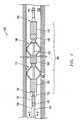
- Fig. 1is a side cross-sectional view of an embodiment of a coiled tubing tractor assembly with a tractor having diagnostic and downhole tools coupled thereto and disposed within a well.
- Fig. 2is a cross-sectional view of coiled tubing and a fiber optic cable of the assembly of Fig. 1 taken from section lines 2-2.
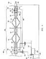
- Fig. 3is a schematic overview of the assembly of Figs. 1 and 2 revealing a communicative pathway from surface equipment through the fiber optic cable and to the diagnostic and downhole tools.
- Fig. 4is a side cross-sectional view of the assembly of Fig. 1 with a comparative depiction of powering hydraulics therebelow.
- Fig. 5is a side cross-sectional view of the tractor of Fig. 1 with a comparative depiction of anchoring hydraulics therebelow.
- Figs. 6A-6Care depictions of the assembly of Fig. 1 with fiber optically controlled hydraulically powered tractor movement from the position of Fig. 6A to the position of Fig. 6C .
- Fig. 7is a depiction of the assembly of Fig. 1 employed in an operation at an oilfield.
- Embodimentsare described with reference to certain downhole tractor assemblies for use in a well at an oilfield.
- dual anchor reciprocating tractor embodimentsare described.
- a variety of configurationsmay be employed.
- embodiments describedmay include a coiled tubing tractor with a diagnostic tool coupled thereto for fiber optic communication with surface equipment at the oilfield.
- the tractoritself may be responsive to fiber optic communications from surface equipment.
- such communicationsmay even be delivered to downhole tools downhole of the tractor and coupled thereto.
- FIG. 1an embodiment of a bottom hole assembly 100 is shown disposed within a downhole region 120 of a well 125.
- the bottom hole assembly 100may be directed to this location to aid in hydrocarbon recovery efforts from the downhole region 120, for example, as detailed with reference to Fig. 7 below.
- the bottom hole assembly 100includes a coiled tubing tractor 104 with adjacent anchors 170, 180. These anchors 170, 180 may be employed to achieve tractor advancement within the well 125 as detailed further below.
- An uphole end of the above noted tractor 104is ultimately coupled to coiled tubing 105 for a coiled tubing operation that may be directed by equipment above the well, for example, from an oilfield surface 700 (see Fig. 7 ).
- a coiled tubing operationthat may be directed by equipment above the well, for example, from an oilfield surface 700 (see Fig. 7 ).
- advancement of the coiled tubing tractor 104 in a downhole directionmay be employed to also pull the coiled tubing 105 in a downhole direction.
- Thismay be particularly advantageous in the case of a highly deviated or horizontal well wherein pushing the coiled tubing 105 alone, by surface equipment, into the well 125 may ultimately yield a fairly limited total attainable well depth.
- a fiber optic cable 101is revealed running through the coiled tubing 105 to provide two-way communication, for example, from the above noted surface equipment.
- the fiber optic cable 101is a line or tether which may weigh no more than about 0.013 kg/m (0.01 lbs./ft.) and include an outer diameter of about 3.81 mm (0.15) inches or less. This is in sharp contrast to a conventional electrically conductive cable which may weigh more than about 0.73 kg/m (0.25 lbs./ft) and have a profile of about 7.62 mm (0.3 inches) or more in outer diameter.
- employing the fiber optic cable 101 for communicationsadds comparatively negligible weight to the overall assembly 100.
- the coiled tubing 105may be much larger than the cable 101, for example having an inner diameter of between about 1 about 3 inches.
- the fiber optic cable 101also leaves the interior of the coiled tubing 105 substantially less affected, for example, in terms of volume availability for fluid flow as described further below.
- a diagnostic tool 137 and signal converter 135are disposed between the tractor 104 and the coiled tubing 105 such that the above noted fiber optic cable 101 actually terminates at the converter 135.
- the signal converter 135may be a conventional conversion device for translating fiber optic signals into electrical signals and vice versa. Thus, it may be employed to obtain and convert fiber optic communications from the cable 101 into electrical signals that may be understood by the diagnostic tool 137 or other electrically compatible downhole equipment. Similarly, data in the form of electrical signals that is routed to the converter 135 from the diagnostic tool 137 or other electrically compatible downhole equipment may be transported as fiber optic signal uphole along the fiber optic cable 101.
- the diagnostic tool 137may be employed to acquire downhole information for transmission back up the fiber optic cable 101 to surface equipment where it may be analyzed and employed in real time during an ongoing well application performed by the assembly 100. Such an application may be achieved with a downhole tool 190 such as for a clean out application wherein the downhole tool 190 includes a clean out nozzle 175 as detailed further below (see Fig. 7 ). Additionally, stimulation, fracturing, milling, fishing, perforating, logging, and other well applications may be performed with the depicted embodiment or alternate embodiments of the assembly 100. Data acquired by the diagnostic tool 137 for use in such applications may include pressure, temperature, pH, particle concentration, viscosity, compression, tension, density, photographic, and depth or location information, among other desired downhole data. Furthermore, aside from the diagnostic tool 137 depicted, alternate sensors located elsewhere throughout the assembly 100 may be employed to acquire such information for transmission to the converter 135 and ultimately up the fiber optic cable 101.
- the above described fiber optic cable 101may be used in place of an electrical cable for transmission of data, large power requirements of the assembly 100 may be met with hydraulic power as detailed further below.
- Smaller power requirements on the other handsuch as for electrically compatible components like the above noted diagnostic tool 137 or solenoids 401, 402, 403; 500, 510 (see Figs. 4 and 5 ).
- a mobile battery 130may be provided by a mobile battery 130.
- a microprocessor coupled to the battery 130may be employed to coordinate the solenoid activity. Sensor data and operator input may similarly be accounted for by the microprocessor.
- the mobile battery 130is positioned at the uphole end of the tractor 104 on an uphole housing 102 thereof.
- the mobile battery 130may be located in a variety of positions on the tractor 104, at a downhole tool 190, on the diagnostic tool 137, at the downhole portion of the coiled tubing 105, or at any other suitable downhole location of the assembly 100. Indeed, multiple mobile batteries may be located at downhole locations of the assembly 100, for separately supplying power to different electronically compatible downhole components of the assembly 100.
- the mobile battery 130may be a lithium based power source with a protective covering for the downhole environment. Such a battery 130 may be configured to supply up to about 100 watts of power or more and be more than capable of meeting the power needs of electrically compatible components such as the diagnostic tool 137.
- an electric wire 131is depicted coupling the mobile battery 130 to the diagnostic tool 137. However, additional electric wires may be provided linking the mobile battery 130 to other electrically compatible components of the assembly 100 (e.g. see wiring 501 of Fig. 5 ).
- each anchor 170, 180is coupled to a housing 102, 115 and an actuator 140, 145 therefor.
- a piston 110is provided that is ultimately coupled uphole to the coiled tubing 105, via the diagnostic tool 137 and converter 135 in the embodiment shown.
- the piston 110runs through the anchors 170, 180, the actuators 140, 145 and the housings 102, 115 as it is employed to hydraulically drive the tractor 104 and pull coiled tubing 105 through the well 125 as detailed further below.
- the bottom hole assembly 100may be particularly adept at traversing highly deviated extended reach wells by employment of the coiled tubing tractor 104.
- the tractor 104may be configured for continuous advancement of the piston 110 noted above in order to achieve continuous downhole movement of the entire assembly 100.
- This continuous downhole movementmay dramatically increase the attainable well depth of the assembly 100.
- conventional coiled tubing 105that is spooled at the well surface and coupled to the piston 110 of a tractor 104 capable of supplying five thousand pounds of force may be advanced in excess of five thousand feet further through a tortuous well 125 due to use of such a continuous movement tractor 104.
- Power requirements for achieving the above noted continuous movement of the tractor 104may be obtained through hydraulics drawn from available pumped fluid through the coiled tubing 105 during an operation. As indicated above, the presence of the fiber optic cable 101 during pumping of the fluid negligibly effects movement of the fluid through the assembly 100. Thus, the higher power requirements of the tractor 104, perhaps in the 4,000 to 6,000 watt range, may be readily met in this manner. With continued reference to Fig. 1 , certain features of such a hydraulically powered tractor 104 have been introduced here. However, the hydraulic powering details are further expounded upon in reference to Figs. 4, 5, and 6A-6B detailed below.
- the fiber optic cable 101may include a fiber optic core 200 encased in a protective jacket 250 to shield the core 200 from downhole conditions and help ensure adequate signal transmission capacity therethrough.
- the cable 101may have an outer diameter of less than about 0.15 inches whereas the inner diameter of the coiled tubing 105 may be between about 1 and about 3 inches.
- the interior of the coiled tubing 105remains substantially unaffected by the presence of the cable 101 as indicated above, for example, during pumping of a fluid through the coiled tubing 105.
- While the fiber optic cable 101provides communicative capacity from surface equipment down to the converter 135, communicative capacity may be extended further downhole beyond the interface of the fiber optic cable 101 and converter 135.
- a signal pathwayis depicted.
- the pathwaymay include an electric wire 131 to provide communicative capacity downhole beyond the converter 135 and diagnostic tool 137, for example to the downhole tool 190 shown.
- the same or similar electrical wiringmay lead from the converter 135, or other components wired thereto, in order to provide communicative capacity to other such components elsewhere throughout the assembly 100 of Fig. 1 .
- a microprocessormay be incorporated with the diagnostic tool for real-time data processing of the collected data.
- the converter 135is provided to extend downhole communicative capacity in light of the fact that many conventional downhole tools and components are at present electrically, as opposed to fiber optically, compatible in terms of data transmission.
- the fiber optic cable 101may actually extend to fiber optically compatible features.
- the downhole tool 190may be powered by hydraulics and perhaps an associated mobile battery 130 (see Fig. 1 ), in one embodiment, it may nevertheless be controlled by signals transmitted directly from the fiber optic cable 101 to the tool 190. This may occur by coupling of a branch of the cable 101 directly to the downhole tool 190 or alternatively by conventional wireless means similar to that noted below.
- the fiber optic cable 101is shown originating from optical surface equipment 300 including a conventional fiber optic light source 305 and a wireless transceiver 307.
- data transmissionmay take place wirelessly between other surface data processing equipment and a surface portion of the cable 101 (e.g. at the coiled tubing reel 703).
- Employing wireless communication in this way at the oilfield surfacemay reduce the physical complexity of maintaining threaded fiber optic cable 101 through coiled tubing 105 on a reel 703 during advancement into the well 125.
- the first anchor 170may act in concert with the adjacent uphole actuator 140 to contact a well wall to achieve immobilization.
- This immobilizationmay take place in a centralized manner.
- centralizationmay occur prior to the immobilization, with the anchor 170 in contact with the well wall but in a mobile state, thereby decreasing the amount of time required to achieve complete immobilization.
- the uphole housing 102may be coupled to the uphole actuator 140. Therefore, as depicted in Fig. 1 and detailed below, the uphole housing 102 may play an important role in the positioning of the uphole anchor 170 and the piston 110 relative to one another.
- the downhole anchor 180may similarly act in concert with an adjacent downhole actuator 145 to achieve immobilization with respect to the well wall, which may again include centralization.
- a downhole housing 115may also play an important role in the positioning of the downhole anchor 180 and the piston 110 relative to one another.
- the anchors 170, 180may be deployed for centralizing when not in a state of immobilization. With such constant deployment, the time between lateral mobility and full immobilization may be significantly reduced for a given anchor 170, 180 in response to pressurization conditions as detailed below. However, in embodiments where a more reduced profile is sought for an anchor 170, 180 in a mobile state, such constant deployment is not required.
- Fig. 4in particular reveals a series of hydraulics between the uphole housing 102 and the downhole housing 115. As detailed further here, these hydraulics are configured such that an influx of hydraulic pressure into one of the housings 102, 115 may lead to a repositioning of the opposite housing 102, 115. As a result, a reliable reciprocating movement of the tractor 104 is achieved without interruption in the forward movement of the piston 110 or any coiled tubing 105 or other equipment coupled thereto.
- a downhole pressurization line 495is coupled to the downhole housing 115.
- the downhole pressurization line 495is presented as a high pressure line for delivering an influx of high pressure to the downhole power chamber 415 from a high pressure line 405 through a series of solenoids 401, 402.
- this line 495may not actually provide pressurization at all times.
- the pressurization provided by the downhole pressurization line 495may arrive in the form of a pressurized hydraulic oil or coiled tubing fluid.
- the piston 110 of the tractor 104is ultimately coupled uphole to the coiled tubing 105 of Fig. 1 that maintains pressurized hydraulic fluid therein.
- a hydraulic supply line 400may be provided from which hydraulic fluid is diverted into the high pressure line 405 noted above.
- a conventional chokemay be positioned in the hydraulic supply line 400 such that a portion of the line at the opposite side of the choke may serve as a low pressure line 410 for purposes detailed below.
- an activation solenoid 401 coupled to the high pressure line 405may be directed to the depicted "on" position by communicative means such as the above detailed electric wire 131. In this manner movement of the tractor 104 as detailed below may begin. However, an operator or equipment at the surface of the operation may similarly direct the activation solenoid 401 to an "off" position closing off the high pressure line 405 connecting to the low pressure line 410 and halting movement of the tractor 104.
- the low pressure line 410may be of the annulus pressure.
- pressurization parametersmay be employed, for the examples described below, about 2,000 PSI pressure differential, relative to the well 125 of Fig. 1 , may be employed to achieve movement of the tractor 104 as detailed.
- hydraulic fluidmay be diverted from the hydraulic supply line 400 into the high pressure line 405 as noted above, and ultimately to the downhole pressurization line 495 (or alternatively to the uphole pressurization line 490 as also noted below).
- the piston 110 of the tractor 104runs entirely therethrough, including through the downhole housing 115 itself.
- a downhole head 419 of the piston 110is housed by the downhole housing 115 and serves to separate the downhole power chamber 415 from a downhole return chamber 416 of the housing 115.
- pressurized hydraulic fluidis delivered to the downhole power chamber 415 by the downhole pressurization line 495.
- the application of sufficient pressure to the downhole piston head 419may move the piston 110 in a downhole direction.
- the volume of the return chamber 416is reduced as the volume of the power chamber 415 grows.
- the piston 110moves in a downhole direction pulling, for example, the coiled tubing 105 of Fig. 1 right along with it.
- the arms of the downhole anchor 180may be initially immobilized with trapped hydraulic fluid of about 500 PSI, for example. However, the advancement of the piston 110, pulling up to several thousand feet of coiled tubing 105 or other equipment, may force up to 15,000 PSI or more on the immobilized arms of the anchor 180. Regardless, the arms of the anchor 180 may be of a self gripping configuration only further immobilizing the anchor 180 in place. These arms of the anchor 180 may include a self-gripping mechanism such as responsive cams relative to a well surface as detailed in U.S. Patent Number 6,629,568 .
- the volume of the downhole return chamber 416decreases.
- hydraulic fluid thereinis forced out of the downhole housing 115 and into a fluid transfer line 480.
- the fluid transfer line 480delivers hydraulic fluid to an uphole return chamber 413 of the uphole housing 102.
- the high pressure influx of hydraulic fluid from the downhole pressurization line 495 into the downhole power chamber 415ultimately results in an influx of hydraulic fluid into the uphole housing 102.
- the influx of hydraulic fluid into the uphole housing 102is achieved through the uphole return chamber 413.
- the hydraulic fluidwould act upon an uphole piston head 417 within the uphole housing 102 in order to drive it in an uphole direction.
- the uphole anchor 170may be centralized without being immobilized at this point in time.
- an increase in pressure within the uphole return chamber 413acts to move the entire uphole housing 102 and anchor 170 in a downhole direction.
- the housing 102 and anchor 170may require no more than between about 22.68 kg (50) and about 136.8 kg (300 pounds) of force for the indicated downhole moving, whereas moving of the uphole piston head 417 and all of the coiled tubing 105 of Fig. 1 or other equipment coupled thereto would likely require several thousand kg (pounds) of force. Therefore, the uphole anchor 170 and housing 102 are moved downhole until the downhole piston head 419 reaches the downhole end of the downhole housing 115 (see also Fig. 6B ).
- any equipmentsuch as the coiled tubing 105 of Fig. 1 that is coupled thereto may be continuously pulled in a downhole direction.
- the piston 110need not stop, wait for a housing (e.g. 102) to move and then proceed downhole.
- the movement of the piston 110is continuous allowing the entire tractor 104 to avoid static friction in the coiled tubing that would be present with each restart of the piston 110 in the downhole direction.
- the advantage of this continuing movementmay provide the tractor 104 with up to twice the total achievable downhole depth by taking advantage of the dynamic condition of the moving system.
- the transfer of hydraulic pressuretakes place from the downhole housing 112 to the uphole housing 115 through the fluid transfer line 480.
- pressure from the immobilized dowhole housing 115is transferred to the mobile uphole housing 102 and anchor 170 to achieve downhole movement thereof, along with the continued advancement of the piston 110.
- the transfer of pressure from the downhole housing 115 to the uphole housing 102will reverse. That is, the uphole housing 102 may be immobilized, the downhole housing 115 made mobile, and hydraulic fluid driven from the uphole housing 102 to the downhole housing 115 in order to achieve downhole movement of the downhole housing 115.
- this switchmay take place as the downhole piston head 419 reaches the end of its downhole advancement completing its effect on the shrinking downhole return chamber 416.
- a position sensor 475may be employed to detect the location of the downhole piston head 419 as it approaches the above noted position.
- the piston head 419may be magnetized and the sensor 475 mounted on the housing 115 and including the capacity to detect the magnetized piston head 419 and its location.
- the sensor 475may be wired to conventional processing means for signaling and directing a switch solenoid 402 to switch the pressure condition from the downhole pressurization line 495 (as shown in Fig. 4 ) to the uphole pressurization line 490 as described here.
- another switch solenoid 403may be directed to switch the low pressure from the uphole pressurization line 490 to the downhole pressurization line 495.
- the downhole anchor 180may be centralized but not immobilized (as is detailed further in the anchor progression description below). Similar to that described above, the advancing uphole piston head 417 forces hydraulic fluid from the return chamber 413 of the uphole housing 102 through the fluid transfer line 480 to the downhole housing 115. Given the non-immobilizing nature of the downhole anchor 180, the influx of pressure into the downhole return chamber 416 results in the moving of the entire downhole housing 115 and anchor 180 in a downhole direction (see Fig. 6C ). Thus, one by one, the anchors 170, 180 and housings 101, 115 continue to reciprocate their way downhole without requiring any interruption in the downhole advancement of the piston 110 or equipment pulled thereby.
- communicative capacity with surface equipmentmay be extended downhole beyond the tractor 104.
- hydraulic powermay be extended beyond the tractor 104 as well.
- a downhole tool 190 in the form of a clean out tool with a nozzle 175may be provided.
- the nozzle 175may be coupled to the supply line 400, for example to wash away debris 760 in the well 125 as depicted in Fig. 7 .
- the anchoring synchronization alluded to aboveis detailed. That is, as evidenced by the progression above, whenever an influx of high pressure is directed to the uphole side of a piston head 417, 419 (via 495 or 490), the associated anchor 170. 180 is immobilized. In other words, whenever the downhole pressurization line 495 pressurizes the downhole power chamber 415, the downhole anchor 180 is immobilized while the uphole anchor 170 remains laterally mobile (e.g. 'centralized' in the embodiments shown). Similarly, following the above noted pressurization switch, whenever the uphole pressurization line 490 pressurizes the uphole power chamber 411, the uphole anchor 170 is immobilized while the downhole anchor 180 becomes laterally mobile.
- the downhole anchor 180may be immobilized with arms in a locked open position as noted above.
- the downhole actuator piston 548 of the downhole actuator 145remains locked in place by the presence of the hydraulic fluid trapped within a closed off downhole actuator line 550. That is, with particular reference to Fig. 5 , the downhole actuator line 550 is closed off by an anchor solenoid 510 that is employed to ensure that one of the anchors 170, 180 is immobilized at any given time.
- Wiring 501may be provided to the anchor solenoid 510 from processing means associated with the position sensor 475 as well as the switch solenoids 402, 403 of Fig. 4 .
- such coordinationmay include a tuned synchronization that maintains downhole movement of the tractor 104 during its operation and avoids any spring-back of coiled tubing in an uphole direction.
- the downhole actuator 145is locked in place.
- the uphole actuator 140is mobile in character. That is, the uphole actuator piston 543 is mobily responsive to radial displacement of the arms of the uphole anchor 170. Therefore, it may be laterally forced downhole in a centralized manner as detailed above.
- the mobility of the uphole actuator piston 543is a result of its corresponding uphole actuator line 525 remaining open through the anchor solenoid 500. In this manner, the line may serve as an overflow or feed line wherein hydraulic fluid may be diverted to or from a pressure reservoir or other storage or release means below the solenoid 500.
- FIGs. 6A-6Cthe uninterrupted synchronization of anchoring and downhole reciprocating advancement of the tractor 104 is depicted.
- the tractor 104is shown with the uphole anchor 170 and housing 102 distanced from the downhole anchor 180 and housing 115 within a well 125.
- the downhole actuator 145is locked as described above such that the downhole anchor 180 is immobilized.
- pressure applied to the downhole power chamber 415 and on the downhole piston head 419advances the piston 110 downhole (see Fig. 6B ).
- the uphole anchor 170may be centralizing in nature, allowing for lateral mobility thereof along with the uphole housing 102 as also depicted below with reference to Fig. 6B .
- the noted lateral mobility of the uphole anchor 170 and housing 102may be effectuated by the influx of pressure into the uphole return chamber 413. That is, given the minimal amount of force required to move the assembly 100, perhaps no more than about 300 PSI of pressure, a downhole movement thereof may be seen with reference to arrow 650.
- arrow 650the fact that it is the downhole movement of the downhole piston head 419 that has lead to the influx of pressure into the chamber 413 thereby providing the downhole movement of the uphole anchor 170.
- the uphole piston head 417appears to move uphole, it is actually the uphole housing 102 thereabout that has moved downhole as indicated. Indeed, the entire piston 110 continues its downhole advancement without interruption as noted below with reference to Fig. 6C .
- the uphole piston head 417appears to resume downhole advancement relative to the uphole housing 102.
- the entire piston 110including the uphole piston head 417 actually maintains uninterrupted downhole advancement.
- the switch solenoids 402, 403change position from that shown in Fig. 4
- the above described switch in pressure conditionsoccurs that leads to an influx of pressure into the uphole power chamber 411.
- the uphole anchor 170is immobilized by the locking of the uphole actuator 140 as detailed above. Therefore, the uphole piston head 417 is driven to the position of Fig. 6C , continuing the downhole advancement of the entire piston 110.
- embodiments described hereinallow for continuous downhole advancement of the piston 110.
- the load pulled by the piston 110such as several thousand meters (feet) of coiled tubing or other equipment may be pulled while substantially avoiding resistance in the form of static friction.
- Downhole advancement of the loadis not interrupted by any need to reset or reposition tractor anchors 170, 180.
- the tractor 104may be able to pull a load of up to about twice the distance as compared to a tractor that must overcome repeated occurrences of static friction.
- a 2268 kg (5,000 lb) capacity tractor of interrupted downhole advancementmust pull about 2268 kg (5,000 lb) after each interruption in advancement.
- the tractor 104may be able to pull the load no further.
- the degree of pull requirementsoon diminishes (e.g.
- tractors 104described herein have up to about twice the downhole pull capacity of a comparable tractor of interrupted downhole advancement.
- coiled tubing 105 and other equipmentare delivered to a downhole region 120 of an oilfield 700 by a delivery truck 701.
- the truck 701accommodates a coiled tubing reel 703 and equipment for threading the coiled tubing 105 through a gooseneck 709 and injector head 707 for advancement of the coiled tubing 105 into the well 125.
- Other conventional equipmentsuch as a blow out preventor stack 711 and a master control valve 713 may be employed in directing the coiled tubing 105 into the well 125 with the assembly 100 coupled to the downhole end thereof.
- the assembly 100is pulled through the deviated well 125 by its tractor 104 which also pulls along the coiled tubing 105 and intervening tools such as the diagnostic tool 137.
- a downhole tool 190is also coupled to the assembly 100, for example, to clean out debris 760 at a downhole location 780 within the well 125.
- a fiber optic cable 101extends along with the coiled tubing 105 from the reel 703 at the surface of the oilfield 700.
- the fiber optic cable 101 disposed at the interior of the coiled tubing 105may be employed for real time two way communication between surface equipment at the oilfield 700 (such as a data acquisition system 733) and downhole tools such as the diagnostic tool 137, the downhole tool 190, or even an activation solenoid 401 of the tractor 104 (see Fig. 4 ). Nevertheless, the pumping of hydraulic fluid through the coiled tubing 105 during the operation is substantially unaffected by the presence of the fiber optic cable 101 due to its characteristics as detailed herein above.
- Embodiments of the coiled tubing tractor assembly detailed herein aboveemploy fiber optic communication through coiled tubing while also providing significant power downhole, for example, to a tractor that may be present at the downhole end of the coiled tubing. This is achieved in a manner that avoids use of large heavy conventional wiring running the length of the coiled tubing and potentially compromising the attainable depth or overall effectiveness of the coiled tubing operation.
Landscapes
- Engineering & Computer Science (AREA)
- Mining & Mineral Resources (AREA)
- Geology (AREA)
- Life Sciences & Earth Sciences (AREA)
- Physics & Mathematics (AREA)
- Remote Sensing (AREA)
- Environmental & Geological Engineering (AREA)
- Fluid Mechanics (AREA)
- General Life Sciences & Earth Sciences (AREA)
- Geochemistry & Mineralogy (AREA)
- Geophysics (AREA)
- Electromagnetism (AREA)
- Earth Drilling (AREA)
- Investigating Materials By The Use Of Optical Means Adapted For Particular Applications (AREA)
- Light Guides In General And Applications Therefor (AREA)
Abstract
Description
- Embodiments described relate to tractors for advancing coiled tubing and other equipment through an underground well. In particular, embodiments of tractors are described that are hydraulically powered and coupled to a fiber optic line through coiled tubing to provide communicative and/or controlling means thereto.
- Coiled tubing operations may be employed at an oilfield to deliver a downhole tool to an operation site for a variety of well intervention applications such as well stimulation, the creating of perforations, or the clean-out of debris from within the well. Coiled tubing operations are particularly adept at providing access to highly deviated or tortuous wells where gravity alone fails to provide access to all regions of the wells. During a coiled tubing operation, a spool of pipe (i.e., a coiled tubing) with a downhole tool at the end thereof is slowly straightened and forcibly pushed into the well. For example, a clean out tool may be delivered to a clean out site within the well in this manner to clean out sand or other undesirable debris thereat.
- Unfortunately, the coiled tubing is susceptible to helical buckling as it is pushed deeper and deeper into the well. That is, depending on the degree of tortuousness and the well depth traversed, the coiled tubing will eventually buckle against the well wall and begin to take on the character of a helical spring. In such circumstances, continued downhole pushing on the coiled tubing simply lodges it more firmly into the well wall ensuring its immobilization and potentially damaging the coiled tubing itself. This has become a more significant matter over the years as the number of tortuous or deviated extended reach wells have become more prevalent. Thus, in order to extend the reach of the coiled tubing, a tractor may be incorporated into a downhole portion thereof for pulling the coiled tubing deeper into the well.
- Tractoring and advancement of the coiled tubing through the well is directed by an operator from the surface of the oilfield. Generally this takes place without information provided to the surface as to the status of the operation at the site of the tractor downhole. That is, the real-time acquisition and transfer of data between the area of the tractor and the surface is generally lacking due to challenges involved in acquiring and transferring the data. For example, mud pulse telemetry or the use of wireline cables between a diagnostic tool at the tractor and the surface may be employed to provide well condition information to an operator. However, in the case of mud pulse telemetry, a temporary obstruction in the well is required in order to transmit a fluid pulse uphole. Additionally, data collection may be limited and the system quite complex. Therefore, mud pulse telemetry is generally not employed. On the other hand, the placement of wireline cables all the way through the coiled tubing and to a diagnostic tool at the tractor location presents several challenges as well. For example, wireline cables are difficult to run through the coiled tubing, take up considerable amount of space within the inner diameter of the coiled tubing, may significantly increase the total weight of the coiled tubing equipment, and present challenges related to tension and control compatibility between the separate wireline and coiled tubing lines themselves.
EP 0 911 483 is considered the closest prior art publication disclosing A2 a drilling system in which a composite load bearing umbilical including electrical and fibre optic conductors is pulled along a borehole by a tractor assembly, which also pushes a bottom hole assembly including a drill bit for drilling the borehole.- In order to address challenges with conventional data transmission between the downhole environment and an oilfield surface, fiber optic communication may be employed. That is, a fiber optic cable may be provided between the surface and a diagnostic tool positioned downhole in a well. In this manner, well information obtained by the diagnostic tool may be transmitted back uphole by fiber optics for analysis. Unlike the above noted wireline cable, a fiber optic cable may be significantly smaller, lighter and easier to insert through the coiled tubing. It may also be readily compatible with wireless transmission means at the surface, thus, making its merging with the coiled tubing at the surface even easier. Furthermore, the inner diameter of the coiled tubing is not significantly compromised by the presence of the small diameter fiber optic cable. Due to its comparatively small weight, the fiber optic cable also fails to present significant incompatibility in terms of differing tensions between itself and the coiled tubing.
- As such, in one embodiment a coiled tubing tractor assembly is provided with a tractor coupled to a coiled tubing having a fiber optic cable therethrough. In one embodiment the fiber optic cable terminates at the monitoring device. The fiber optic cable may also be used to control movement of the coiled tubing tractor. Additionally, a tool may be coupled to the coiled tubing tractor wherein the coiled tubing tractor provides communicative means between the tool and the monitoring device.
Fig. 1 is a side cross-sectional view of an embodiment of a coiled tubing tractor assembly with a tractor having diagnostic and downhole tools coupled thereto and disposed within a well.Fig. 2 is a cross-sectional view of coiled tubing and a fiber optic cable of the assembly ofFig. 1 taken from section lines 2-2.Fig. 3 is a schematic overview of the assembly ofFigs. 1 and2 revealing a communicative pathway from surface equipment through the fiber optic cable and to the diagnostic and downhole tools.Fig. 4 is a side cross-sectional view of the assembly ofFig. 1 with a comparative depiction of powering hydraulics therebelow.Fig. 5 is a side cross-sectional view of the tractor ofFig. 1 with a comparative depiction of anchoring hydraulics therebelow.Figs. 6A-6C are depictions of the assembly ofFig. 1 with fiber optically controlled hydraulically powered tractor movement from the position ofFig. 6A to the position ofFig. 6C .Fig. 7 is a depiction of the assembly ofFig. 1 employed in an operation at an oilfield.- Embodiments are described with reference to certain downhole tractor assemblies for use in a well at an oilfield. In particular, dual anchor reciprocating tractor embodiments are described. However, a variety of configurations may be employed. Regardless, embodiments described may include a coiled tubing tractor with a diagnostic tool coupled thereto for fiber optic communication with surface equipment at the oilfield. In fact, the tractor itself may be responsive to fiber optic communications from surface equipment. Furthermore, such communications may even be delivered to downhole tools downhole of the tractor and coupled thereto.
- Referring now to
Fig. 1 an embodiment of abottom hole assembly 100 is shown disposed within adownhole region 120 of awell 125. Thebottom hole assembly 100 may be directed to this location to aid in hydrocarbon recovery efforts from thedownhole region 120, for example, as detailed with reference toFig. 7 below. Thebottom hole assembly 100 includes a coiledtubing tractor 104 withadjacent anchors anchors well 125 as detailed further below. - An uphole end of the above noted
tractor 104 is ultimately coupled to coiledtubing 105 for a coiled tubing operation that may be directed by equipment above the well, for example, from an oilfield surface 700 (seeFig. 7 ). In this manner, advancement of the coiledtubing tractor 104 in a downhole direction may be employed to also pull the coiledtubing 105 in a downhole direction. This may be particularly advantageous in the case of a highly deviated or horizontal well wherein pushing the coiledtubing 105 alone, by surface equipment, into thewell 125 may ultimately yield a fairly limited total attainable well depth. - Continuing with reference to
Fig. 1 , a fiberoptic cable 101 is revealed running through the coiledtubing 105 to provide two-way communication, for example, from the above noted surface equipment. The fiberoptic cable 101 is a line or tether which may weigh no more than about 0.013 kg/m (0.01 lbs./ft.) and include an outer diameter of about 3.81 mm (0.15) inches or less. This is in sharp contrast to a conventional electrically conductive cable which may weigh more than about 0.73 kg/m (0.25 lbs./ft) and have a profile of about 7.62 mm (0.3 inches) or more in outer diameter. Thus, employing the fiberoptic cable 101 for communications adds comparatively negligible weight to theoverall assembly 100. Furthermore, thecoiled tubing 105 may be much larger than thecable 101, for example having an inner diameter of between about 1 about 3 inches. Thus, thefiber optic cable 101 also leaves the interior of the coiledtubing 105 substantially less affected, for example, in terms of volume availability for fluid flow as described further below. - As shown in
Fig. 1 , adiagnostic tool 137 andsignal converter 135 are disposed between thetractor 104 and thecoiled tubing 105 such that the above notedfiber optic cable 101 actually terminates at theconverter 135. Thesignal converter 135 may be a conventional conversion device for translating fiber optic signals into electrical signals and vice versa. Thus, it may be employed to obtain and convert fiber optic communications from thecable 101 into electrical signals that may be understood by thediagnostic tool 137 or other electrically compatible downhole equipment. Similarly, data in the form of electrical signals that is routed to theconverter 135 from thediagnostic tool 137 or other electrically compatible downhole equipment may be transported as fiber optic signal uphole along thefiber optic cable 101. - The
diagnostic tool 137 may be employed to acquire downhole information for transmission back up thefiber optic cable 101 to surface equipment where it may be analyzed and employed in real time during an ongoing well application performed by theassembly 100. Such an application may be achieved with adownhole tool 190 such as for a clean out application wherein thedownhole tool 190 includes a clean outnozzle 175 as detailed further below (seeFig. 7 ). Additionally, stimulation, fracturing, milling, fishing, perforating, logging, and other well applications may be performed with the depicted embodiment or alternate embodiments of theassembly 100. Data acquired by thediagnostic tool 137 for use in such applications may include pressure, temperature, pH, particle concentration, viscosity, compression, tension, density, photographic, and depth or location information, among other desired downhole data. Furthermore, aside from thediagnostic tool 137 depicted, alternate sensors located elsewhere throughout theassembly 100 may be employed to acquire such information for transmission to theconverter 135 and ultimately up thefiber optic cable 101. - Given that the above described fiber
optic cable 101 may be used in place of an electrical cable for transmission of data, large power requirements of theassembly 100 may be met with hydraulic power as detailed further below. Smaller power requirements on the other hand, such as for electrically compatible components like the above noteddiagnostic tool 137 orsolenoids Figs. 4 and5 ). may be provided by amobile battery 130. Additionally, a microprocessor coupled to thebattery 130 may be employed to coordinate the solenoid activity. Sensor data and operator input may similarly be accounted for by the microprocessor. In the embodiment shown, themobile battery 130 is positioned at the uphole end of thetractor 104 on anuphole housing 102 thereof. However, themobile battery 130 may be located in a variety of positions on thetractor 104, at adownhole tool 190, on thediagnostic tool 137, at the downhole portion of the coiledtubing 105, or at any other suitable downhole location of theassembly 100. Indeed, multiple mobile batteries may be located at downhole locations of theassembly 100, for separately supplying power to different electronically compatible downhole components of theassembly 100. - In one embodiment, the
mobile battery 130 may be a lithium based power source with a protective covering for the downhole environment. Such abattery 130 may be configured to supply up to about 100 watts of power or more and be more than capable of meeting the power needs of electrically compatible components such as thediagnostic tool 137. In the embodiment shown, anelectric wire 131 is depicted coupling themobile battery 130 to thediagnostic tool 137. However, additional electric wires may be provided linking themobile battery 130 to other electrically compatible components of the assembly 100 (e.g. seewiring 501 ofFig. 5 ). - Continuing again with reference to
Fig. 1 , eachanchor housing actuator piston 110 is provided that is ultimately coupled uphole to the coiledtubing 105, via thediagnostic tool 137 andconverter 135 in the embodiment shown. Thepiston 110 runs through theanchors actuators housings tractor 104 and pullcoiled tubing 105 through the well 125 as detailed further below. - As indicated, the
bottom hole assembly 100 may be particularly adept at traversing highly deviated extended reach wells by employment of the coiledtubing tractor 104. In fact, as detailed inFigs. 6A-6C , thetractor 104 may be configured for continuous advancement of thepiston 110 noted above in order to achieve continuous downhole movement of theentire assembly 100. This continuous downhole movement may dramatically increase the attainable well depth of theassembly 100. For example, conventional coiledtubing 105 that is spooled at the well surface and coupled to thepiston 110 of atractor 104 capable of supplying five thousand pounds of force may be advanced in excess of five thousand feet further through a tortuous well 125 due to use of such acontinuous movement tractor 104. - Power requirements for achieving the above noted continuous movement of the
tractor 104 may be obtained through hydraulics drawn from available pumped fluid through the coiledtubing 105 during an operation. As indicated above, the presence of thefiber optic cable 101 during pumping of the fluid negligibly effects movement of the fluid through theassembly 100. Thus, the higher power requirements of thetractor 104, perhaps in the 4,000 to 6,000 watt range, may be readily met in this manner. With continued reference toFig. 1 , certain features of such a hydraulically poweredtractor 104 have been introduced here. However, the hydraulic powering details are further expounded upon in reference toFigs. 4, 5, and 6A-6B detailed below. - Referring now to
Fig. 2 , a cross-sectional view of the coiledtubing 105 andfiber optic cable 101 is depicted, taken from section lines 2-2 ofFig. 1 . Thefiber optic cable 101 may include afiber optic core 200 encased in aprotective jacket 250 to shield the core 200 from downhole conditions and help ensure adequate signal transmission capacity therethrough. As indicated above, thecable 101 may have an outer diameter of less than about 0.15 inches whereas the inner diameter of the coiledtubing 105 may be between about 1 and about 3 inches. Thus, the interior of the coiledtubing 105 remains substantially unaffected by the presence of thecable 101 as indicated above, for example, during pumping of a fluid through the coiledtubing 105. - While the
fiber optic cable 101 provides communicative capacity from surface equipment down to theconverter 135, communicative capacity may be extended further downhole beyond the interface of thefiber optic cable 101 andconverter 135. For example, as noted above and depicted inFig. 3 , a signal pathway is depicted. The pathway may include anelectric wire 131 to provide communicative capacity downhole beyond theconverter 135 anddiagnostic tool 137, for example to thedownhole tool 190 shown. The same or similar electrical wiring may lead from theconverter 135, or other components wired thereto, in order to provide communicative capacity to other such components elsewhere throughout theassembly 100 ofFig. 1 . Additionally, a microprocessor may be incorporated with the diagnostic tool for real-time data processing of the collected data. - It is worth noting that the
converter 135 is provided to extend downhole communicative capacity in light of the fact that many conventional downhole tools and components are at present electrically, as opposed to fiber optically, compatible in terms of data transmission. However, this is not required and in alternate embodiments, thefiber optic cable 101 may actually extend to fiber optically compatible features. For example, while thedownhole tool 190 may be powered by hydraulics and perhaps an associated mobile battery 130 (seeFig. 1 ), in one embodiment, it may nevertheless be controlled by signals transmitted directly from thefiber optic cable 101 to thetool 190. This may occur by coupling of a branch of thecable 101 directly to thedownhole tool 190 or alternatively by conventional wireless means similar to that noted below. - Continuing with reference to
Fig. 3 , with added reference toFig. 7 , thefiber optic cable 101 is shown originating fromoptical surface equipment 300 including a conventional fiber opticlight source 305 and awireless transceiver 307. In this manner, data transmission may take place wirelessly between other surface data processing equipment and a surface portion of the cable 101 (e.g. at the coiled tubing reel 703). Employing wireless communication in this way at the oilfield surface may reduce the physical complexity of maintaining threadedfiber optic cable 101 through coiledtubing 105 on areel 703 during advancement into thewell 125. - Continuing now with reference to
Figs. 1 and 4 , thefirst anchor 170, referred to herein as theuphole anchor 170, may act in concert with the adjacentuphole actuator 140 to contact a well wall to achieve immobilization. This immobilization may take place in a centralized manner. Furthermore, centralization may occur prior to the immobilization, with theanchor 170 in contact with the well wall but in a mobile state, thereby decreasing the amount of time required to achieve complete immobilization. Regardless, theuphole housing 102 may be coupled to theuphole actuator 140. Therefore, as depicted inFig. 1 and detailed below, theuphole housing 102 may play an important role in the positioning of theuphole anchor 170 and thepiston 110 relative to one another. - The
downhole anchor 180 may similarly act in concert with an adjacentdownhole actuator 145 to achieve immobilization with respect to the well wall, which may again include centralization. Likewise, adownhole housing 115 may also play an important role in the positioning of thedownhole anchor 180 and thepiston 110 relative to one another. As alluded to above, for the embodiments described herein, theanchors anchor anchor - With particular reference to
Fig. 4 and added reference toFig. 1 , the manner in which thetractor 104 is advanced within the well 125 by the advancinganchors Fig. 4 , in particular reveals a series of hydraulics between theuphole housing 102 and thedownhole housing 115. As detailed further here, these hydraulics are configured such that an influx of hydraulic pressure into one of thehousings opposite housing tractor 104 is achieved without interruption in the forward movement of thepiston 110 or anycoiled tubing 105 or other equipment coupled thereto. - Continuing with reference to
Fig. 4 adownhole pressurization line 495 is coupled to thedownhole housing 115. For sake of description here, thedownhole pressurization line 495 is presented as a high pressure line for delivering an influx of high pressure to thedownhole power chamber 415 from ahigh pressure line 405 through a series ofsolenoids line 495 may not actually provide pressurization at all times. - The pressurization provided by the
downhole pressurization line 495 may arrive in the form of a pressurized hydraulic oil or coiled tubing fluid. For example, in one embodiment, thepiston 110 of thetractor 104 is ultimately coupled uphole to the coiledtubing 105 ofFig. 1 that maintains pressurized hydraulic fluid therein. Ahydraulic supply line 400 may be provided from which hydraulic fluid is diverted into thehigh pressure line 405 noted above. In fact, a conventional choke may be positioned in thehydraulic supply line 400 such that a portion of the line at the opposite side of the choke may serve as alow pressure line 410 for purposes detailed below. - As shown in
Fig. 4 , anactivation solenoid 401 coupled to thehigh pressure line 405 may be directed to the depicted "on" position by communicative means such as the above detailedelectric wire 131. In this manner movement of thetractor 104 as detailed below may begin. However, an operator or equipment at the surface of the operation may similarly direct theactivation solenoid 401 to an "off" position closing off thehigh pressure line 405 connecting to thelow pressure line 410 and halting movement of thetractor 104. Thelow pressure line 410 may be of the annulus pressure. - While a variety of pressurization parameters may be employed, for the examples described below, about 2,000 PSI pressure differential, relative to the well 125 of
Fig. 1 , may be employed to achieve movement of thetractor 104 as detailed. In order to achieve this pressurization, hydraulic fluid may be diverted from thehydraulic supply line 400 into thehigh pressure line 405 as noted above, and ultimately to the downhole pressurization line 495 (or alternatively to theuphole pressurization line 490 as also noted below). - The
piston 110 of thetractor 104 runs entirely therethrough, including through thedownhole housing 115 itself. Adownhole head 419 of thepiston 110 is housed by thedownhole housing 115 and serves to separate thedownhole power chamber 415 from adownhole return chamber 416 of thehousing 115. As indicated above, pressurized hydraulic fluid is delivered to thedownhole power chamber 415 by thedownhole pressurization line 495. Thus, when thedownhole anchor 180 is immobilized as detailed below, the application of sufficient pressure to thedownhole piston head 419 may move thepiston 110 in a downhole direction. Accordingly, the volume of thereturn chamber 416 is reduced as the volume of thepower chamber 415 grows. For this period, thepiston 110 moves in a downhole direction pulling, for example, thecoiled tubing 105 ofFig. 1 right along with it. - Of note is the fact that the arms of the
downhole anchor 180 may be initially immobilized with trapped hydraulic fluid of about 500 PSI, for example. However, the advancement of thepiston 110, pulling up to several thousand feet ofcoiled tubing 105 or other equipment, may force up to 15,000 PSI or more on the immobilized arms of theanchor 180. Regardless, the arms of theanchor 180 may be of a self gripping configuration only further immobilizing theanchor 180 in place. These arms of theanchor 180 may include a self-gripping mechanism such as responsive cams relative to a well surface as detailed inU.S. Patent Number 6,629,568 . - As the
downhole piston head 419 is forced in the downhole direction as noted above, the volume of thedownhole return chamber 416 decreases. Thus, hydraulic fluid therein is forced out of thedownhole housing 115 and into afluid transfer line 480. Thefluid transfer line 480 delivers hydraulic fluid to anuphole return chamber 413 of theuphole housing 102. Thus, the high pressure influx of hydraulic fluid from thedownhole pressurization line 495 into thedownhole power chamber 415 ultimately results in an influx of hydraulic fluid into theuphole housing 102. - The influx of hydraulic fluid into the
uphole housing 102 is achieved through theuphole return chamber 413. Thus, it appears as though the hydraulic fluid would act upon anuphole piston head 417 within theuphole housing 102 in order to drive it in an uphole direction. However, as described further below, theuphole anchor 170 may be centralized without being immobilized at this point in time. Thus, an increase in pressure within theuphole return chamber 413 acts to move the entireuphole housing 102 andanchor 170 in a downhole direction. For example, thehousing 102 andanchor 170 may require no more than between about 22.68 kg (50) and about 136.8 kg (300 pounds) of force for the indicated downhole moving, whereas moving of theuphole piston head 417 and all of the coiledtubing 105 ofFig. 1 or other equipment coupled thereto would likely require several thousand kg (pounds) of force. Therefore, theuphole anchor 170 andhousing 102 are moved downhole until thedownhole piston head 419 reaches the downhole end of the downhole housing 115 (see alsoFig. 6B ). - The anchoring and hydraulic synchronization described to this point allow for the continuous advancement of the
piston 110. Thus, any equipment, such as thecoiled tubing 105 ofFig. 1 that is coupled thereto may be continuously pulled in a downhole direction. This is a particular result of the series hydraulics employed. That is, hydraulic pressure is applied to one of thehousings 115 which thereby employs movement of thepiston 110 downhole as a corollary to the downhole advancement of theopposite housing 102. There is no measurable interruption in the advancement of thepiston 110. For example, thepiston 110 need not stop, wait for a housing (e.g. 102) to move and then proceed downhole. Rather, the movement of thepiston 110 is continuous allowing theentire tractor 104 to avoid static friction in the coiled tubing that would be present with each restart of thepiston 110 in the downhole direction. As detailed below, the advantage of this continuing movement may provide thetractor 104 with up to twice the total achievable downhole depth by taking advantage of the dynamic condition of the moving system. - As detailed above, the transfer of hydraulic pressure takes place from the downhole housing 112 to the
uphole housing 115 through thefluid transfer line 480. In particular, pressure from the immobilizeddowhole housing 115 is transferred to the mobileuphole housing 102 andanchor 170 to achieve downhole movement thereof, along with the continued advancement of thepiston 110. However, at some point, the transfer of pressure from thedownhole housing 115 to theuphole housing 102 will reverse. That is, theuphole housing 102 may be immobilized, thedownhole housing 115 made mobile, and hydraulic fluid driven from theuphole housing 102 to thedownhole housing 115 in order to achieve downhole movement of thedownhole housing 115. As detailed below, this switch may take place as thedownhole piston head 419 reaches the end of its downhole advancement completing its effect on the shrinkingdownhole return chamber 416. - A
position sensor 475 may be employed to detect the location of thedownhole piston head 419 as it approaches the above noted position. For example, in one embodiment, thepiston head 419 may be magnetized and thesensor 475 mounted on thehousing 115 and including the capacity to detect themagnetized piston head 419 and its location. Thesensor 475 may be wired to conventional processing means for signaling and directing aswitch solenoid 402 to switch the pressure condition from the downhole pressurization line 495 (as shown inFig. 4 ) to theuphole pressurization line 490 as described here. Additionally, anotherswitch solenoid 403 may be directed to switch the low pressure from theuphole pressurization line 490 to thedownhole pressurization line 495. Thus, with theuphole anchor 170 now immobilized at this point in time as detailed below, an influx of high pressure into thepower chamber 411 of theuphole housing 102 may now drive theuphole piston head 417 in a downhole direction. - As the
piston 110 is advanced downhole via pressure on thepiston head 417 as indicated above, thedownhole anchor 180 may be centralized but not immobilized (as is detailed further in the anchor progression description below). Similar to that described above, the advancinguphole piston head 417 forces hydraulic fluid from thereturn chamber 413 of theuphole housing 102 through thefluid transfer line 480 to thedownhole housing 115. Given the non-immobilizing nature of thedownhole anchor 180, the influx of pressure into thedownhole return chamber 416 results in the moving of the entiredownhole housing 115 andanchor 180 in a downhole direction (seeFig. 6C ). Thus, one by one, theanchors housings piston 110 or equipment pulled thereby. - As described above with reference to
Fig. 3 , communicative capacity with surface equipment may be extended downhole beyond thetractor 104. Additionally, as depicted inFig. 4 , hydraulic power may be extended beyond thetractor 104 as well. For example, adownhole tool 190 in the form of a clean out tool with anozzle 175 may be provided. Thenozzle 175 may be coupled to thesupply line 400, for example to wash awaydebris 760 in the well 125 as depicted inFig. 7 . - Continuing now with reference to
Figs. 4 and5 , the anchoring synchronization alluded to above is detailed. That is, as evidenced by the progression above, whenever an influx of high pressure is directed to the uphole side of apiston head 417, 419 (via 495 or 490), the associatedanchor 170. 180 is immobilized. In other words, whenever thedownhole pressurization line 495 pressurizes thedownhole power chamber 415, thedownhole anchor 180 is immobilized while theuphole anchor 170 remains laterally mobile (e.g. 'centralized' in the embodiments shown). Similarly, following the above noted pressurization switch, whenever theuphole pressurization line 490 pressurizes theuphole power chamber 411, theuphole anchor 170 is immobilized while thedownhole anchor 180 becomes laterally mobile. - With reference to the
downhole pressurization line 495 supplying high pressure to thedownhole housing 115, thedownhole anchor 180 may be immobilized with arms in a locked open position as noted above. Upon closer examination, thedownhole actuator piston 548 of thedownhole actuator 145 remains locked in place by the presence of the hydraulic fluid trapped within a closed offdownhole actuator line 550. That is, with particular reference toFig. 5 , thedownhole actuator line 550 is closed off by ananchor solenoid 510 that is employed to ensure that one of theanchors anchor solenoid 510 from processing means associated with theposition sensor 475 as well as theswitch solenoids Fig. 4 . In this manner coordination between the immobilization ofanchors Fig. 4 may be ensured. In particular, such coordination may include a tuned synchronization that maintains downhole movement of thetractor 104 during its operation and avoids any spring-back of coiled tubing in an uphole direction. - As shown in
Fig. 5 and described above, thedownhole actuator 145 is locked in place. However, at this same time theuphole actuator 140 is mobile in character. That is, theuphole actuator piston 543 is mobily responsive to radial displacement of the arms of theuphole anchor 170. Therefore, it may be laterally forced downhole in a centralized manner as detailed above. The mobility of theuphole actuator piston 543 is a result of its correspondinguphole actuator line 525 remaining open through theanchor solenoid 500. In this manner, the line may serve as an overflow or feed line wherein hydraulic fluid may be diverted to or from a pressure reservoir or other storage or release means below thesolenoid 500. - Referring now to
Figs. 6A-6C , the uninterrupted synchronization of anchoring and downhole reciprocating advancement of thetractor 104 is depicted. Starting withFig. 6A , thetractor 104 is shown with theuphole anchor 170 andhousing 102 distanced from thedownhole anchor 180 andhousing 115 within a well 125. Thedownhole actuator 145 is locked as described above such that thedownhole anchor 180 is immobilized. Thus, pressure applied to thedownhole power chamber 415 and on thedownhole piston head 419 advances thepiston 110 downhole (seeFig. 6B ). At this same time, theuphole anchor 170 may be centralizing in nature, allowing for lateral mobility thereof along with theuphole housing 102 as also depicted below with reference toFig. 6B . - Referring now to
Fig. 6B , the noted lateral mobility of theuphole anchor 170 andhousing 102 may be effectuated by the influx of pressure into theuphole return chamber 413. That is, given the minimal amount of force required to move theassembly 100, perhaps no more than about 300 PSI of pressure, a downhole movement thereof may be seen with reference toarrow 650. Of note is the fact that it is the downhole movement of thedownhole piston head 419 that has lead to the influx of pressure into thechamber 413 thereby providing the downhole movement of theuphole anchor 170. Furthermore, while theuphole piston head 417 appears to move uphole, it is actually theuphole housing 102 thereabout that has moved downhole as indicated. Indeed, theentire piston 110 continues its downhole advancement without interruption as noted below with reference toFig. 6C . - As shown in
Fig. 6C , theuphole piston head 417 appears to resume downhole advancement relative to theuphole housing 102. However, as indicated above, theentire piston 110, including theuphole piston head 417 actually maintains uninterrupted downhole advancement. For example, once theswitch solenoids Fig. 4 , the above described switch in pressure conditions occurs that leads to an influx of pressure into theuphole power chamber 411. At this same time, theuphole anchor 170 is immobilized by the locking of theuphole actuator 140 as detailed above. Therefore, theuphole piston head 417 is driven to the position ofFig. 6C , continuing the downhole advancement of theentire piston 110. Indeed, this downhole advancement of theuphole piston head 417 relative to theuphole housing 102 leads to an influx of pressure into thedownhole return chamber 416. Thus, with the move to a mobile state of centralization of thedownhole anchor 180 at this time, as detailed above, thedownhole anchor 180 advances further downhole (see arrow 675) to the position shown inFig. 6C . - As indicated, embodiments described herein allow for continuous downhole advancement of the
piston 110. Thus, the load pulled by thepiston 110, such as several thousand meters (feet) of coiled tubing or other equipment may be pulled while substantially avoiding resistance in the form of static friction. Downhole advancement of the load is not interrupted by any need to reset or reposition tractor anchors 170, 180. Thus, in the face of dynamic friction alone, thetractor 104 may be able to pull a load of up to about twice the distance as compared to a tractor that must overcome repeated occurrences of static friction. For example, where just under a 2268 kg (5,000 lb) pull is required to advance a load downhole, a 2268 kg (5,000 lb) capacity tractor of interrupted downhole advancement must pull about 2268 kg (5,000 lb) after each interruption in advancement. Thus, as soon as the pull requirement increases to beyond 2268 kg (5,000 lbs) based on depth achieved, thetractor 104 may be able to pull the load no further. However, for embodiments of thetractor 104 depicted herein, even those subjected to a 2268 kg (5,000 lb) pull requirement at the outset of downhole advancement, the degree of pull requirement soon diminishes (e.g. to as low as about 1134 kg (2,500 lbs.) Only once the depth of advancement increases the pull requirement by another (1134 kg (2,500 lbs) does the 2268 kg (5,000 lb.)capacity tractor 104 reach its downhole limit. For this reason, embodiments oftractors 104 described herein have up to about twice the downhole pull capacity of a comparable tractor of interrupted downhole advancement. - Referring now to
Fig. 7 , an embodiment of thebottom hole assembly 100 is depicted in the well 125 as described above. In the embodiment shown, coiledtubing 105 and other equipment are delivered to adownhole region 120 of anoilfield 700 by adelivery truck 701. Thetruck 701 accommodates acoiled tubing reel 703 and equipment for threading thecoiled tubing 105 through agooseneck 709 andinjector head 707 for advancement of the coiledtubing 105 into thewell 125. Other conventional equipment such as a blow outpreventor stack 711 and amaster control valve 713 may be employed in directing thecoiled tubing 105 into the well 125 with theassembly 100 coupled to the downhole end thereof. - The
assembly 100 is pulled through the deviated well 125 by itstractor 104 which also pulls along the coiledtubing 105 and intervening tools such as thediagnostic tool 137. Adownhole tool 190 is also coupled to theassembly 100, for example, to clean outdebris 760 at adownhole location 780 within thewell 125. With added reference toFig. 1 , afiber optic cable 101 extends along with thecoiled tubing 105 from thereel 703 at the surface of theoilfield 700. As detailed above, thefiber optic cable 101 disposed at the interior of the coiledtubing 105 may be employed for real time two way communication between surface equipment at the oilfield 700 (such as a data acquisition system 733) and downhole tools such as thediagnostic tool 137, thedownhole tool 190, or even anactivation solenoid 401 of the tractor 104 (seeFig. 4 ). Nevertheless, the pumping of hydraulic fluid through the coiledtubing 105 during the operation is substantially unaffected by the presence of thefiber optic cable 101 due to its characteristics as detailed herein above. - Embodiments of the coiled tubing tractor assembly detailed herein above employ fiber optic communication through coiled tubing while also providing significant power downhole, for example, to a tractor that may be present at the downhole end of the coiled tubing. This is achieved in a manner that avoids use of large heavy conventional wiring running the length of the coiled tubing and potentially compromising the attainable depth or overall effectiveness of the coiled tubing operation.
- The preceding description has been presented with reference to presently preferred embodiments. Persons skilled in the art and technology to which these embodiments pertain will appreciate that alterations and changes in the described structures and methods of operation may be practiced without meaningfully departing from the principle, and scope of these embodiments. For example, embodiments depicted herein reveal a two arm configuration for each anchor similar to that of
US App. Ser. No. 60/890,577 . However, other configurations with other numbers of arms for each anchor may be employed. Furthermore, the foregoing description should not be read as pertaining only to the precise structures described and shown in the accompanying drawings, but rather should be read as consistent with and as support for the following claims, which are to have their fullest and fairest scope.
Claims (16)
- A coiled tubing tractors assembly comprising: a hydraulically driven coiled tubing tractor (104) for substantially continuous advancement through a well, said tractor having a first housing (102) about a first head (417) of a piston (110), the first head being arranged to move in response to an influx of hydraulic pressure into the first housing, said tractor having a second housing (115) about a second head (419) of the piston to display moveable responsiveness to the moving of the first head relative to the first housing and coiled tubing (105) coupled to said coiled tubing tractor to be pulled along the well thereby; the assembly beingcharacterized by a fiber optic (101) disposed along with the coiled tubing and at the interior of the coiled tubing to provide a communicative pathway between surface equipment at the well and through said coiled tubing to said coiled tubing tractor (104) or to a diagnostic tool (137) coupled to the coiled tubing tractor.
- The coiled tubing tractor assembly of claim 1, wherein said fiber optic (101) is configured for controlling the advancement of the coiled tubing tractor (104).
- The coiled tubing tractor assembly of claim 1 or claim 2, wherein the diagnostic tool (137) is configured to acquire downhole measurements and is coupled to said fiber optic (101).
- The coiled tubing tractor assembly of claim 3, wherein the diagnostic tool (137) is configured to acquire downhole measurements chosen from the group consisting of pressure, temperature, pH, particle concentration, viscosity, density, compression, tension, depth, location, and photographic information.
- The coiled tubing tractor assembly of claim 3, further comprising a signal converter (135) coupled to said fiber optic (101) for conversion of a fiber optic signal therefrom to an electronic signal compatible with said diagnostic tool (137).
- The coiled tubing tractor assembly of claim 1, further comprising a downhole tool (190) coupled to said coiled tubing (105) and positioned downhole of said coiled tubing tractor (104) in the well, said downhole tool being communicatively coupled to said fiber optic through said coiled tubing tractor.
- The coiled tubing tractor assembly of claim 6, wherein said downhole tool (190) is configured for an application in the well which is one of a clean out application, 3 stimulation application, a fracturing application, a milling application, a fishing application, and a perforating application.
- The coiled tubing tractor assembly of claim I, further comprising a signal converter (135) adjacent said coiled tubing tractor (104) and coupled to said tiber optic (101) for conversion of a fiber optic signal therefrom to an electronic signal compatible with equipment in the well.
- The coiled tubing tractor assembly of claim 8, wherein the equipment is one of said coiled tubing tractor (104), a downhole tool (190) coupled to said coiled tubing (110), and a diagnostic tool (137) coupled to said fiber optic (101).
- The coiled tubing tractor assembly of claim 1, wherein said hydraulically powered tractor (104) further comprises: a first anchor (170) coupled to said first housing (102) for immobilization thereof during the moving of the first head; and a second anchor (180) coupled to said second housing (115) to allow lateral mobility thereof for the responsiveness to the moving of the first head.
- The coiled tubing tractor assembly of claim 1, further comprising a mobile battery (130) coupled to one of said coiled tubing tractor(104), a downhole tool (190) hydraulically coupled to said coiled tubing, a diagnostic tool (137) coupled to said fiber optic, and a signal converter (135) coupled to said fiber optic.
- The coiled tubing tractor assembly of claim 1, wherein said fiber optic (101) is less than about 0.01 pounds per foot (15gms/m), and less than about 0.15 inches (3.8 mm) in outer diameter, and wherein said coiled tubing is between about 1 and about 3 inches (2.54 to 7.62) in inner diameter.
- The coiled tubing tractor assembly of claim 1, further comprising a wireless transceiver (307) coupled to an uphole end of said fiber optic (101) for wireless exchange of the information with the surface equipment.
- A method of performing a coiled tubing operation in a well, the method comprising: providing a fiber optic (101) disposed along with a coiled tubing (105) and at the interior of the coiled tubing; coupling a hydraulically driven tractor (104) to the coiled tubing for advancing the coiled tubing in the well; establishing a communicative pathway from surface equipment at the well and through said fiber optic (101) in said coiled tubing (105); acquiring information relative to the well with a diagnostic tool (137) that is coupled to the fiber optic; and employing the information in real-time during the operation.
- The method of claim 14, wherein said advancing is controlled via the fiber optic (101).
- The method of claim 14, further comprising: activating a downhole tool (190) with the fiber optic (101), the downhole tool being coupled to the coiled tubing (105) and positioned downhole of the tractor, and employing the activated downhole tool for an application in the well.
Applications Claiming Priority (4)
| Application Number | Priority Date | Filing Date | Title |
|---|---|---|---|
| US88311507P | 2007-01-02 | 2007-01-02 | |
| US11/772,181US20080066963A1 (en) | 2006-09-15 | 2007-06-30 | Hydraulically driven tractor |
| US11/923,895US9500058B2 (en) | 2004-05-28 | 2007-10-25 | Coiled tubing tractor assembly |
| PCT/IB2007/055338WO2008081404A1 (en) | 2007-01-02 | 2007-12-28 | Coiled tubing tractor assembly |
Publications (2)
| Publication Number | Publication Date |
|---|---|
| EP2097609A1 EP2097609A1 (en) | 2009-09-09 |
| EP2097609B1true EP2097609B1 (en) | 2012-08-22 |
Family
ID=39363819
Family Applications (1)
| Application Number | Title | Priority Date | Filing Date |
|---|---|---|---|
| EP07859542ANot-in-forceEP2097609B1 (en) | 2007-01-02 | 2007-12-28 | Coiled tubing tractor assembly |
Country Status (4)
| Country | Link |
|---|---|
| US (1) | US9500058B2 (en) |
| EP (1) | EP2097609B1 (en) |
| NO (1) | NO20092402L (en) |
| WO (1) | WO2008081404A1 (en) |
Cited By (1)
| Publication number | Priority date | Publication date | Assignee | Title |
|---|---|---|---|---|
| GB2636344A (en)* | 2023-10-25 | 2025-06-18 | Ga Drilling As | Downhole apparatus for use with a continuous work string |
Families Citing this family (80)
| Publication number | Priority date | Publication date | Assignee | Title |
|---|---|---|---|---|
| US6464003B2 (en) | 2000-05-18 | 2002-10-15 | Western Well Tool, Inc. | Gripper assembly for downhole tractors |
| US8245796B2 (en)* | 2000-12-01 | 2012-08-21 | Wwt International, Inc. | Tractor with improved valve system |
| WO2005090739A1 (en)* | 2004-03-17 | 2005-09-29 | Western Well Tool, Inc. | Roller link toggle gripper for downhole tractor |
| US9500058B2 (en) | 2004-05-28 | 2016-11-22 | Schlumberger Technology Corporation | Coiled tubing tractor assembly |
| US7617873B2 (en) | 2004-05-28 | 2009-11-17 | Schlumberger Technology Corporation | System and methods using fiber optics in coiled tubing |
| US9540889B2 (en)* | 2004-05-28 | 2017-01-10 | Schlumberger Technology Corporation | Coiled tubing gamma ray detector |
| US7624808B2 (en)* | 2006-03-13 | 2009-12-01 | Western Well Tool, Inc. | Expandable ramp gripper |
| US7748476B2 (en) | 2006-11-14 | 2010-07-06 | Wwt International, Inc. | Variable linkage assisted gripper |
| US9133673B2 (en)* | 2007-01-02 | 2015-09-15 | Schlumberger Technology Corporation | Hydraulically driven tandem tractor assembly |
| CN102187046B (en) | 2008-08-20 | 2015-04-29 | 福罗能源股份有限公司 | Method, system and assembly for advancement of a borehole using a high power laser |
| US9242309B2 (en) | 2012-03-01 | 2016-01-26 | Foro Energy Inc. | Total internal reflection laser tools and methods |
| US9719302B2 (en) | 2008-08-20 | 2017-08-01 | Foro Energy, Inc. | High power laser perforating and laser fracturing tools and methods of use |
| US9089928B2 (en) | 2008-08-20 | 2015-07-28 | Foro Energy, Inc. | Laser systems and methods for the removal of structures |
| US9664012B2 (en) | 2008-08-20 | 2017-05-30 | Foro Energy, Inc. | High power laser decomissioning of multistring and damaged wells |
| US9074422B2 (en) | 2011-02-24 | 2015-07-07 | Foro Energy, Inc. | Electric motor for laser-mechanical drilling |
| US9244235B2 (en) | 2008-10-17 | 2016-01-26 | Foro Energy, Inc. | Systems and assemblies for transferring high power laser energy through a rotating junction |
| US9267330B2 (en) | 2008-08-20 | 2016-02-23 | Foro Energy, Inc. | Long distance high power optical laser fiber break detection and continuity monitoring systems and methods |
| US9347271B2 (en) | 2008-10-17 | 2016-05-24 | Foro Energy, Inc. | Optical fiber cable for transmission of high power laser energy over great distances |
| US9080425B2 (en) | 2008-10-17 | 2015-07-14 | Foro Energy, Inc. | High power laser photo-conversion assemblies, apparatuses and methods of use |
| US8571368B2 (en) | 2010-07-21 | 2013-10-29 | Foro Energy, Inc. | Optical fiber configurations for transmission of laser energy over great distances |
| US8662160B2 (en) | 2008-08-20 | 2014-03-04 | Foro Energy Inc. | Systems and conveyance structures for high power long distance laser transmission |
| US9669492B2 (en) | 2008-08-20 | 2017-06-06 | Foro Energy, Inc. | High power laser offshore decommissioning tool, system and methods of use |
| US10301912B2 (en)* | 2008-08-20 | 2019-05-28 | Foro Energy, Inc. | High power laser flow assurance systems, tools and methods |
| US9027668B2 (en) | 2008-08-20 | 2015-05-12 | Foro Energy, Inc. | Control system for high power laser drilling workover and completion unit |
| US9138786B2 (en) | 2008-10-17 | 2015-09-22 | Foro Energy, Inc. | High power laser pipeline tool and methods of use |
| US8627901B1 (en) | 2009-10-01 | 2014-01-14 | Foro Energy, Inc. | Laser bottom hole assembly |
| US9360631B2 (en) | 2008-08-20 | 2016-06-07 | Foro Energy, Inc. | Optics assembly for high power laser tools |
| US8485278B2 (en)* | 2009-09-29 | 2013-07-16 | Wwt International, Inc. | Methods and apparatuses for inhibiting rotational misalignment of assemblies in expandable well tools |
| DK177946B9 (en) | 2009-10-30 | 2015-04-20 | Maersk Oil Qatar As | well Interior |
| DK179473B1 (en) | 2009-10-30 | 2018-11-27 | Total E&P Danmark A/S | A device and a system and a method of moving in a tubular channel |
| US8602115B2 (en)* | 2009-12-01 | 2013-12-10 | Schlumberger Technology Corporation | Grip enhanced tractoring |
| DK178339B1 (en) | 2009-12-04 | 2015-12-21 | Maersk Oil Qatar As | An apparatus for sealing off a part of a wall in a section drilled into an earth formation, and a method for applying the apparatus |
| US8805614B2 (en)* | 2010-08-31 | 2014-08-12 | Schlumberger Technology Corporation | Downhole sample analysis method |
| BR112013021478A2 (en) | 2011-02-24 | 2016-10-11 | Foro Energy Inc | High power laser-mechanical drilling method |
| DK177547B1 (en) | 2011-03-04 | 2013-10-07 | Maersk Olie & Gas | Process and system for well and reservoir management in open-zone developments as well as process and system for production of crude oil |
| EP2715887A4 (en) | 2011-06-03 | 2016-11-23 | Foro Energy Inc | Rugged passively cooled high power laser fiber optic connectors and methods of use |
| US9399269B2 (en) | 2012-08-02 | 2016-07-26 | Foro Energy, Inc. | Systems, tools and methods for high power laser surface decommissioning and downhole welding |
| US9976351B2 (en)* | 2011-08-05 | 2018-05-22 | Coiled Tubing Specialties, Llc | Downhole hydraulic Jetting Assembly |
| US10087717B2 (en)* | 2011-10-17 | 2018-10-02 | Schlumberger Technology Corporation | Dual use cable with fiber optics for use in wellbore operations |
| US9447648B2 (en) | 2011-10-28 | 2016-09-20 | Wwt North America Holdings, Inc | High expansion or dual link gripper |
| RU2487238C1 (en)* | 2012-02-09 | 2013-07-10 | Открытое акционерное общество "Нефтяная компания "Роснефть" | Down-hole testing and measuring complex and method for its installation in horizontal well |
| US8931558B1 (en) | 2012-03-22 | 2015-01-13 | Full Flow Technologies, Llc | Flow line cleanout device |
| US10047592B2 (en) | 2012-05-18 | 2018-08-14 | Schlumberger Technology Corporation | System and method for performing a perforation operation |
| WO2014036430A2 (en) | 2012-09-01 | 2014-03-06 | Foro Energy, Inc. | Reduced mechanical energy well control systems and methods of use |
| CA2891500A1 (en) | 2012-11-15 | 2014-05-22 | Foro Energy, Inc. | High power laser hydraulic fructuring, stimulation, tools systems and methods |
| BR112015011460A2 (en) | 2012-11-20 | 2017-07-11 | Halliburton Energy Services Inc | apparatus, system, and processor-implemented method |
| EP2923039B1 (en) | 2012-11-20 | 2017-09-20 | Halliburton Energy Services, Inc. | Acoustic signal enhancement apparatus, systems, and methods |
| WO2014204535A1 (en) | 2013-03-15 | 2014-12-24 | Foro Energy, Inc. | High power laser fluid jets and beam paths using deuterium oxide |
| MX384463B (en)* | 2013-09-13 | 2025-03-14 | Schlumberger Technology Bv | Electrically conductive fiber optic steel line for flexible piping activities. |
| US9488020B2 (en) | 2014-01-27 | 2016-11-08 | Wwt North America Holdings, Inc. | Eccentric linkage gripper |
| WO2016028298A1 (en)* | 2014-08-21 | 2016-02-25 | Viking Fishing And Oil Tools, Llc | Downhole anchoring apparatus |
| CN104533327B (en)* | 2014-12-19 | 2017-05-10 | 中国石油大学(华东) | Walking type coiled tubing well drilling tractor |
| EP3250785B1 (en) | 2015-01-26 | 2022-09-21 | Services Pétroliers Schlumberger | Electrically conductive fiber optic slickline for coiled tubing operations |
| US20160215578A1 (en)* | 2015-01-27 | 2016-07-28 | Schlumberger Technology Corporation | Subsurface Deployment for Monitoring Along a Borehole |
| AU2016223214B2 (en) | 2015-02-24 | 2019-01-31 | Coiled Tubing Specialties, Llc | Steerable hydraulic jetting nozzle, and guidance system for downhole boring device |
| RU2603322C1 (en)* | 2015-09-10 | 2016-11-27 | Общество с ограниченной ответственностью Предприятие "ФХС-ПНГ" | Method of downhole tools delivery to bottoms of drilled wells with complex profile, carrying out geophysical survey and complex for its implementation |
| US10221687B2 (en) | 2015-11-26 | 2019-03-05 | Merger Mines Corporation | Method of mining using a laser |
| US10597945B2 (en) | 2016-02-12 | 2020-03-24 | Dover Chemical Corporation | Coiled-tubing fluid-lubricant composition and related methods |
| CN105909234A (en)* | 2016-05-18 | 2016-08-31 | 北京富地勘察测绘有限公司 | Automatic downhole centering detecting device |
| US10049789B2 (en) | 2016-06-09 | 2018-08-14 | Schlumberger Technology Corporation | Compression and stretch resistant components and cables for oilfield applications |
| CA3035347A1 (en) | 2016-10-10 | 2018-04-19 | Halliburton Energy Services, Inc. | Downhole fiber installation equipment and method |
| US10955264B2 (en) | 2018-01-24 | 2021-03-23 | Saudi Arabian Oil Company | Fiber optic line for monitoring of well operations |
| GB2584237B (en) | 2018-01-29 | 2022-04-06 | Kureha Corp | Degradable downhole plug |
| US10927625B2 (en) | 2018-05-10 | 2021-02-23 | Colorado School Of Mines | Downhole tractor for use in a wellbore |
| CN109098678B (en)* | 2018-10-19 | 2024-01-26 | 中石化江汉石油工程有限公司 | Throwaway nipple for transporting tractor perforating tools in horizontal wells |
| US11002093B2 (en) | 2019-02-04 | 2021-05-11 | Saudi Arabian Oil Company | Semi-autonomous downhole taxi with fiber optic communication |
| US10995574B2 (en) | 2019-04-24 | 2021-05-04 | Saudi Arabian Oil Company | Subterranean well thrust-propelled torpedo deployment system and method |
| US11365958B2 (en) | 2019-04-24 | 2022-06-21 | Saudi Arabian Oil Company | Subterranean well torpedo distributed acoustic sensing system and method |
| US10883810B2 (en) | 2019-04-24 | 2021-01-05 | Saudi Arabian Oil Company | Subterranean well torpedo system |
| CN112727442B (en)* | 2019-10-28 | 2024-02-06 | 中国石油化工股份有限公司 | Coiled tubing visual well repair operation tubular column and method |
| US11346177B2 (en) | 2019-12-04 | 2022-05-31 | Saudi Arabian Oil Company | Repairable seal assemblies for oil and gas applications |
| US11408229B1 (en) | 2020-03-27 | 2022-08-09 | Coiled Tubing Specialties, Llc | Extendible whipstock, and method for increasing the bend radius of a hydraulic jetting hose downhole |
| US11591871B1 (en) | 2020-08-28 | 2023-02-28 | Coiled Tubing Specialties, Llc | Electrically-actuated resettable downhole anchor and/or packer, and method of setting, releasing, and resetting |
| CN112065312B (en)* | 2020-09-30 | 2023-11-10 | 中国石油天然气集团有限公司 | Hydraulic telescopic coiled tubing tractor for dense gas operation and use method |
| CN113638707A (en)* | 2021-08-17 | 2021-11-12 | 中国石油化工股份有限公司 | Photoelectric well logging tractor |
| US11959666B2 (en) | 2021-08-26 | 2024-04-16 | Colorado School Of Mines | System and method for harvesting geothermal energy from a subterranean formation |
| US12031396B2 (en) | 2022-11-29 | 2024-07-09 | Saudi Arabian Oil Company | Method and apparatus of guided extend reach tractor |
| US12320214B2 (en)* | 2023-01-31 | 2025-06-03 | Schlumberger Technology Corporation | Anchor assemblies for use on a cable and processes for using same |
| US12252946B2 (en) | 2023-07-06 | 2025-03-18 | Halliburton Energy Services, Inc. | Wellbore tubular anchor sub and seal for modular completion interface |
| US12331603B1 (en) | 2024-07-17 | 2025-06-17 | Halliburton Energy Services, Inc. | Methods and apparatus to decouple downhole tool speed from conveyance tools |
Family Cites Families (59)
| Publication number | Priority date | Publication date | Assignee | Title |
|---|---|---|---|---|
| US2558427A (en) | 1946-05-08 | 1951-06-26 | Schlumberger Well Surv Corp | Casing collar locator |
| DE2818656A1 (en) | 1978-04-27 | 1979-10-31 | Siemens Ag | Wideband cable network communication system - consists of insulated light conductors twisted with another light conductor and with two insulated metal wires |
| DE8515470U1 (en) | 1985-05-25 | 1985-12-19 | Felten & Guilleaume Energietechnik Gmbh, 5000 Koeln | Power cables, especially for voltages from 6 to 60 kV, with inserted optical fibers |
| JPS622412A (en) | 1985-06-28 | 1987-01-08 | 株式会社フジクラ | Optical fiber composite overhead line |
| US4859054A (en) | 1987-07-10 | 1989-08-22 | The United States Of America As Represented By The United States Department Of Energy | Proximity fuze |
| FR2661762B1 (en) | 1990-05-03 | 1992-07-31 | Storck Jean | METHOD AND DEVICE FOR TRANSACTING BETWEEN A FIRST AND AT LEAST A SECOND DATA MEDIUM AND MEDIUM FOR THIS PURPOSE. |
| US5485745A (en)* | 1991-05-20 | 1996-01-23 | Halliburton Company | Modular downhole inspection system for coiled tubing |
| GB2275953B (en) | 1992-09-01 | 1996-04-17 | Halliburton Co | Downhole logging tool |
| US5332048A (en) | 1992-10-23 | 1994-07-26 | Halliburton Company | Method and apparatus for automatic closed loop drilling system |
| US5542471A (en) | 1993-11-16 | 1996-08-06 | Loral Vought System Corporation | Heat transfer element having the thermally conductive fibers |
| US5573225A (en) | 1994-05-06 | 1996-11-12 | Dowell, A Division Of Schlumberger Technology Corporation | Means for placing cable within coiled tubing |
| US6868906B1 (en) | 1994-10-14 | 2005-03-22 | Weatherford/Lamb, Inc. | Closed-loop conveyance systems for well servicing |
| US6157893A (en) | 1995-03-31 | 2000-12-05 | Baker Hughes Incorporated | Modified formation testing apparatus and method |
| US6581455B1 (en) | 1995-03-31 | 2003-06-24 | Baker Hughes Incorporated | Modified formation testing apparatus with borehole grippers and method of formation testing |
| US5495547A (en) | 1995-04-12 | 1996-02-27 | Western Atlas International, Inc. | Combination fiber-optic/electrical conductor well logging cable |
| GB2318601B (en) | 1995-08-22 | 2000-03-29 | Western Well Tool Inc | Puller-thruster downhole tool |
| GB9606673D0 (en) | 1996-03-29 | 1996-06-05 | Sensor Dynamics Ltd | Apparatus for the remote measurement of physical parameters |
| US5794703A (en) | 1996-07-03 | 1998-08-18 | Ctes, L.C. | Wellbore tractor and method of moving an item through a wellbore |
| US5913003A (en) | 1997-01-10 | 1999-06-15 | Lucent Technologies Inc. | Composite fiber optic distribution cable |
| US6281489B1 (en) | 1997-05-02 | 2001-08-28 | Baker Hughes Incorporated | Monitoring of downhole parameters and tools utilizing fiber optics |
| US6296066B1 (en) | 1997-10-27 | 2001-10-02 | Halliburton Energy Services, Inc. | Well system |
| US6923273B2 (en) | 1997-10-27 | 2005-08-02 | Halliburton Energy Services, Inc. | Well system |
| US6009216A (en) | 1997-11-05 | 1999-12-28 | Cidra Corporation | Coiled tubing sensor system for delivery of distributed multiplexed sensors |
| US6192983B1 (en) | 1998-04-21 | 2001-02-27 | Baker Hughes Incorporated | Coiled tubing strings and installation methods |
| US6247536B1 (en) | 1998-07-14 | 2001-06-19 | Camco International Inc. | Downhole multiplexer and related methods |
| DE29816469U1 (en) | 1998-09-14 | 1998-12-24 | Huang, Wen-Sheng, Tung Hsiao Chen, Miao Li | Steel rope structure with optical fibers |
| US6347674B1 (en) | 1998-12-18 | 2002-02-19 | Western Well Tool, Inc. | Electrically sequenced tractor |
| US6467557B1 (en) | 1998-12-18 | 2002-10-22 | Western Well Tool, Inc. | Long reach rotary drilling assembly |
| GB2378469B (en) | 1998-12-18 | 2003-04-02 | Western Well Tool Inc | Electrically sequenced tractor |
| BR9908000A (en) | 1998-12-18 | 2002-01-15 | Western Well Tool Inc | Electro-hydraulically controlled traction propeller |
| US6273189B1 (en) | 1999-02-05 | 2001-08-14 | Halliburton Energy Services, Inc. | Downhole tractor |
| US6519568B1 (en) | 1999-06-15 | 2003-02-11 | Schlumberger Technology Corporation | System and method for electronic data delivery |
| WO2001009478A1 (en) | 1999-07-30 | 2001-02-08 | Western Well Tool, Inc. | Long reach rotary drilling assembly |
| US6349768B1 (en) | 1999-09-30 | 2002-02-26 | Schlumberger Technology Corporation | Method and apparatus for all multilateral well entry |
| US6399546B1 (en) | 1999-10-15 | 2002-06-04 | Schlumberger Technology Corporation | Fluid system having controllable reversible viscosity |
| US6367366B1 (en) | 1999-12-02 | 2002-04-09 | Western Well Tool, Inc. | Sensor assembly |
| US6464003B2 (en) | 2000-05-18 | 2002-10-15 | Western Well Tool, Inc. | Gripper assembly for downhole tractors |
| US20020007945A1 (en) | 2000-04-06 | 2002-01-24 | David Neuroth | Composite coiled tubing with embedded fiber optic sensors |
| US6935423B2 (en) | 2000-05-02 | 2005-08-30 | Halliburton Energy Services, Inc. | Borehole retention device |
| US6419014B1 (en) | 2000-07-20 | 2002-07-16 | Schlumberger Technology Corporation | Apparatus and method for orienting a downhole tool |
| US6789621B2 (en) | 2000-08-03 | 2004-09-14 | Schlumberger Technology Corporation | Intelligent well system and method |
| US20040035199A1 (en) | 2000-11-01 | 2004-02-26 | Baker Hughes Incorporated | Hydraulic and mechanical noise isolation for improved formation testing |
| US6474152B1 (en) | 2000-11-02 | 2002-11-05 | Schlumberger Technology Corporation | Methods and apparatus for optically measuring fluid compressibility downhole |
| US7121364B2 (en) | 2003-02-10 | 2006-10-17 | Western Well Tool, Inc. | Tractor with improved valve system |
| US6679341B2 (en) | 2000-12-01 | 2004-01-20 | Western Well Tool, Inc. | Tractor with improved valve system |
| US6629568B2 (en) | 2001-08-03 | 2003-10-07 | Schlumberger Technology Corporation | Bi-directional grip mechanism for a wide range of bore sizes |
| US6715559B2 (en) | 2001-12-03 | 2004-04-06 | Western Well Tool, Inc. | Gripper assembly for downhole tractors |
| CA2495342C (en) | 2002-08-15 | 2008-08-26 | Schlumberger Canada Limited | Use of distributed temperature sensors during wellbore treatments |
| US6978832B2 (en) | 2002-09-09 | 2005-12-27 | Halliburton Energy Services, Inc. | Downhole sensing with fiber in the formation |
| US7090020B2 (en) | 2002-10-30 | 2006-08-15 | Schlumberger Technology Corp. | Multi-cycle dump valve |
| WO2004072433A2 (en) | 2003-02-10 | 2004-08-26 | Western Well Tool Inc. | Downhole tractor with improved valve system |
| WO2004114487A1 (en) | 2003-06-20 | 2004-12-29 | Schlumberger Canada Limited | Method and apparatus for deploying a line in coiled tubing |
| US7140437B2 (en) | 2003-07-21 | 2006-11-28 | Halliburton Energy Services, Inc. | Apparatus and method for monitoring a treatment process in a production interval |
| US7124819B2 (en)* | 2003-12-01 | 2006-10-24 | Schlumberger Technology Corporation | Downhole fluid pumping apparatus and method |
| WO2005090739A1 (en) | 2004-03-17 | 2005-09-29 | Western Well Tool, Inc. | Roller link toggle gripper for downhole tractor |
| US9500058B2 (en) | 2004-05-28 | 2016-11-22 | Schlumberger Technology Corporation | Coiled tubing tractor assembly |
| US7617873B2 (en) | 2004-05-28 | 2009-11-17 | Schlumberger Technology Corporation | System and methods using fiber optics in coiled tubing |
| US7448448B2 (en)* | 2005-12-15 | 2008-11-11 | Schlumberger Technology Corporation | System and method for treatment of a well |
| US20070215345A1 (en)* | 2006-03-14 | 2007-09-20 | Theodore Lafferty | Method And Apparatus For Hydraulic Fracturing And Monitoring |
- 2007
- 2007-10-25USUS11/923,895patent/US9500058B2/ennot_activeExpired - Fee Related
- 2007-12-28WOPCT/IB2007/055338patent/WO2008081404A1/enactiveApplication Filing
- 2007-12-28EPEP07859542Apatent/EP2097609B1/ennot_activeNot-in-force
- 2009
- 2009-06-24NONO20092402Apatent/NO20092402L/ennot_activeApplication Discontinuation
Cited By (1)
| Publication number | Priority date | Publication date | Assignee | Title |
|---|---|---|---|---|
| GB2636344A (en)* | 2023-10-25 | 2025-06-18 | Ga Drilling As | Downhole apparatus for use with a continuous work string |
Also Published As
| Publication number | Publication date |
|---|---|
| US9500058B2 (en) | 2016-11-22 |
| EP2097609A1 (en) | 2009-09-09 |
| WO2008081404A1 (en) | 2008-07-10 |
| US20080073077A1 (en) | 2008-03-27 |
| NO20092402L (en) | 2009-09-24 |
Similar Documents
| Publication | Publication Date | Title |
|---|---|---|
| EP2097609B1 (en) | Coiled tubing tractor assembly | |
| US8573313B2 (en) | Well servicing methods and systems | |
| EP1029147B1 (en) | Reciprocating running tool | |
| US6173787B1 (en) | Method and system intended for measurements in a horizontal pipe | |
| AU2003286632B2 (en) | Method and apparatus for installing control lines in a well | |
| US8522869B2 (en) | Optical coiled tubing log assembly | |
| CA2537502C (en) | Separable plug for use in a wellbore | |
| CA2584827C (en) | System and method for releasing and retrieving memory tool with wireline in well pipe | |
| US9175518B2 (en) | Anchoring systems for drilling tools | |
| US10392889B2 (en) | Downhole cable grab assembly and method of use | |
| US7743849B2 (en) | Dual tractor drilling system | |
| WO2016081155A1 (en) | Method for drilling extended reach lateral wellbores | |
| GB2330161A (en) | Flexible extension for borehole logging instruments | |
| US20160237812A1 (en) | Fiber Optic Slickline and Tractor System | |
| CA2861839A1 (en) | Method and apparatus of distributed systems for extending reach in oilfield applications | |
| US8307917B2 (en) | Downhole injector system for CT and wireline drilling | |
| US10822942B2 (en) | Telemetry system including a super conductor for a resource exploration and recovery system | |
| Cahyadi et al. | Application of E-Line-Based Electro-Mechanical Hydraulic Tool for Gas Lift Valve Change-Out in High Angle and High Casing Pressure Well |
Legal Events
| Date | Code | Title | Description |
|---|---|---|---|
| PUAI | Public reference made under article 153(3) epc to a published international application that has entered the european phase | Free format text:ORIGINAL CODE: 0009012 | |
| 17P | Request for examination filed | Effective date:20090622 | |
| AK | Designated contracting states | Kind code of ref document:A1 Designated state(s):AT BE BG CH CY CZ DE DK EE ES FI FR GB GR HU IE IS IT LI LT LU LV MC MT NL PL PT RO SE SI SK TR | |
| DAX | Request for extension of the european patent (deleted) | ||
| 17Q | First examination report despatched | Effective date:20100324 | |
| REG | Reference to a national code | Ref country code:DE Ref legal event code:R079 Ref document number:602007025018 Country of ref document:DE Free format text:PREVIOUS MAIN CLASS: E21B0004180000 Ipc:E21B0047120000 | |
| GRAP | Despatch of communication of intention to grant a patent | Free format text:ORIGINAL CODE: EPIDOSNIGR1 | |
| RIC1 | Information provided on ipc code assigned before grant | Ipc:E21B 47/12 20120101AFI20120117BHEP Ipc:E21B 23/14 20060101ALI20120117BHEP Ipc:E21B 4/18 20060101ALI20120117BHEP | |
| GRAS | Grant fee paid | Free format text:ORIGINAL CODE: EPIDOSNIGR3 | |
| GRAA | (expected) grant | Free format text:ORIGINAL CODE: 0009210 | |
| AK | Designated contracting states | Kind code of ref document:B1 Designated state(s):AT BE BG CH CY CZ DE DK EE ES FI FR GB GR HU IE IS IT LI LT LU LV MC MT NL PL PT RO SE SI SK TR | |
| REG | Reference to a national code | Ref country code:GB Ref legal event code:FG4D | |
| REG | Reference to a national code | Ref country code:CH Ref legal event code:EP | |
| REG | Reference to a national code | Ref country code:IE Ref legal event code:FG4D | |
| REG | Reference to a national code | Ref country code:AT Ref legal event code:REF Ref document number:572134 Country of ref document:AT Kind code of ref document:T Effective date:20120915 | |
| REG | Reference to a national code | Ref country code:DE Ref legal event code:R096 Ref document number:602007025018 Country of ref document:DE Effective date:20121018 | |
| REG | Reference to a national code | Ref country code:NL Ref legal event code:VDEP Effective date:20120822 | |
| REG | Reference to a national code | Ref country code:AT Ref legal event code:MK05 Ref document number:572134 Country of ref document:AT Kind code of ref document:T Effective date:20120822 | |
| REG | Reference to a national code | Ref country code:LT Ref legal event code:MG4D Effective date:20120822 | |
| PG25 | Lapsed in a contracting state [announced via postgrant information from national office to epo] | Ref country code:LT Free format text:LAPSE BECAUSE OF FAILURE TO SUBMIT A TRANSLATION OF THE DESCRIPTION OR TO PAY THE FEE WITHIN THE PRESCRIBED TIME-LIMIT Effective date:20120822 Ref country code:AT Free format text:LAPSE BECAUSE OF FAILURE TO SUBMIT A TRANSLATION OF THE DESCRIPTION OR TO PAY THE FEE WITHIN THE PRESCRIBED TIME-LIMIT Effective date:20120822 Ref country code:IS Free format text:LAPSE BECAUSE OF FAILURE TO SUBMIT A TRANSLATION OF THE DESCRIPTION OR TO PAY THE FEE WITHIN THE PRESCRIBED TIME-LIMIT Effective date:20121222 Ref country code:CY Free format text:LAPSE BECAUSE OF FAILURE TO SUBMIT A TRANSLATION OF THE DESCRIPTION OR TO PAY THE FEE WITHIN THE PRESCRIBED TIME-LIMIT Effective date:20120822 Ref country code:FI Free format text:LAPSE BECAUSE OF FAILURE TO SUBMIT A TRANSLATION OF THE DESCRIPTION OR TO PAY THE FEE WITHIN THE PRESCRIBED TIME-LIMIT Effective date:20120822 | |
| PG25 | Lapsed in a contracting state [announced via postgrant information from national office to epo] | Ref country code:SE Free format text:LAPSE BECAUSE OF FAILURE TO SUBMIT A TRANSLATION OF THE DESCRIPTION OR TO PAY THE FEE WITHIN THE PRESCRIBED TIME-LIMIT Effective date:20120822 Ref country code:SI Free format text:LAPSE BECAUSE OF FAILURE TO SUBMIT A TRANSLATION OF THE DESCRIPTION OR TO PAY THE FEE WITHIN THE PRESCRIBED TIME-LIMIT Effective date:20120822 Ref country code:PT Free format text:LAPSE BECAUSE OF FAILURE TO SUBMIT A TRANSLATION OF THE DESCRIPTION OR TO PAY THE FEE WITHIN THE PRESCRIBED TIME-LIMIT Effective date:20121224 Ref country code:GR Free format text:LAPSE BECAUSE OF FAILURE TO SUBMIT A TRANSLATION OF THE DESCRIPTION OR TO PAY THE FEE WITHIN THE PRESCRIBED TIME-LIMIT Effective date:20121123 Ref country code:BE Free format text:LAPSE BECAUSE OF FAILURE TO SUBMIT A TRANSLATION OF THE DESCRIPTION OR TO PAY THE FEE WITHIN THE PRESCRIBED TIME-LIMIT Effective date:20120822 Ref country code:LV Free format text:LAPSE BECAUSE OF FAILURE TO SUBMIT A TRANSLATION OF THE DESCRIPTION OR TO PAY THE FEE WITHIN THE PRESCRIBED TIME-LIMIT Effective date:20120822 | |
| PG25 | Lapsed in a contracting state [announced via postgrant information from national office to epo] | Ref country code:NL Free format text:LAPSE BECAUSE OF FAILURE TO SUBMIT A TRANSLATION OF THE DESCRIPTION OR TO PAY THE FEE WITHIN THE PRESCRIBED TIME-LIMIT Effective date:20120822 | |
| PG25 | Lapsed in a contracting state [announced via postgrant information from national office to epo] | Ref country code:DK Free format text:LAPSE BECAUSE OF FAILURE TO SUBMIT A TRANSLATION OF THE DESCRIPTION OR TO PAY THE FEE WITHIN THE PRESCRIBED TIME-LIMIT Effective date:20120822 Ref country code:CZ Free format text:LAPSE BECAUSE OF FAILURE TO SUBMIT A TRANSLATION OF THE DESCRIPTION OR TO PAY THE FEE WITHIN THE PRESCRIBED TIME-LIMIT Effective date:20120822 Ref country code:EE Free format text:LAPSE BECAUSE OF FAILURE TO SUBMIT A TRANSLATION OF THE DESCRIPTION OR TO PAY THE FEE WITHIN THE PRESCRIBED TIME-LIMIT Effective date:20120822 Ref country code:ES Free format text:LAPSE BECAUSE OF FAILURE TO SUBMIT A TRANSLATION OF THE DESCRIPTION OR TO PAY THE FEE WITHIN THE PRESCRIBED TIME-LIMIT Effective date:20121203 Ref country code:RO Free format text:LAPSE BECAUSE OF FAILURE TO SUBMIT A TRANSLATION OF THE DESCRIPTION OR TO PAY THE FEE WITHIN THE PRESCRIBED TIME-LIMIT Effective date:20120822 | |
| PG25 | Lapsed in a contracting state [announced via postgrant information from national office to epo] | Ref country code:IT Free format text:LAPSE BECAUSE OF FAILURE TO SUBMIT A TRANSLATION OF THE DESCRIPTION OR TO PAY THE FEE WITHIN THE PRESCRIBED TIME-LIMIT Effective date:20120822 Ref country code:PL Free format text:LAPSE BECAUSE OF FAILURE TO SUBMIT A TRANSLATION OF THE DESCRIPTION OR TO PAY THE FEE WITHIN THE PRESCRIBED TIME-LIMIT Effective date:20120822 Ref country code:SK Free format text:LAPSE BECAUSE OF FAILURE TO SUBMIT A TRANSLATION OF THE DESCRIPTION OR TO PAY THE FEE WITHIN THE PRESCRIBED TIME-LIMIT Effective date:20120822 | |
| PLBE | No opposition filed within time limit | Free format text:ORIGINAL CODE: 0009261 | |
| STAA | Information on the status of an ep patent application or granted ep patent | Free format text:STATUS: NO OPPOSITION FILED WITHIN TIME LIMIT | |
| 26N | No opposition filed | Effective date:20130523 | |
| PG25 | Lapsed in a contracting state [announced via postgrant information from national office to epo] | Ref country code:BG Free format text:LAPSE BECAUSE OF FAILURE TO SUBMIT A TRANSLATION OF THE DESCRIPTION OR TO PAY THE FEE WITHIN THE PRESCRIBED TIME-LIMIT Effective date:20121122 Ref country code:MC Free format text:LAPSE BECAUSE OF NON-PAYMENT OF DUE FEES Effective date:20121231 | |
| REG | Reference to a national code | Ref country code:CH Ref legal event code:PL | |
| REG | Reference to a national code | Ref country code:DE Ref legal event code:R097 Ref document number:602007025018 Country of ref document:DE Effective date:20130523 | |
| REG | Reference to a national code | Ref country code:IE Ref legal event code:MM4A | |
| REG | Reference to a national code | Ref country code:FR Ref legal event code:ST Effective date:20130830 | |
| REG | Reference to a national code | Ref country code:DE Ref legal event code:R119 Ref document number:602007025018 Country of ref document:DE Effective date:20130702 | |
| PG25 | Lapsed in a contracting state [announced via postgrant information from national office to epo] | Ref country code:CH Free format text:LAPSE BECAUSE OF NON-PAYMENT OF DUE FEES Effective date:20121231 Ref country code:IE Free format text:LAPSE BECAUSE OF NON-PAYMENT OF DUE FEES Effective date:20121228 Ref country code:DE Free format text:LAPSE BECAUSE OF NON-PAYMENT OF DUE FEES Effective date:20130702 Ref country code:LI Free format text:LAPSE BECAUSE OF NON-PAYMENT OF DUE FEES Effective date:20121231 | |
| PG25 | Lapsed in a contracting state [announced via postgrant information from national office to epo] | Ref country code:FR Free format text:LAPSE BECAUSE OF NON-PAYMENT OF DUE FEES Effective date:20130102 Ref country code:MT Free format text:LAPSE BECAUSE OF FAILURE TO SUBMIT A TRANSLATION OF THE DESCRIPTION OR TO PAY THE FEE WITHIN THE PRESCRIBED TIME-LIMIT Effective date:20120822 | |
| PG25 | Lapsed in a contracting state [announced via postgrant information from national office to epo] | Ref country code:TR Free format text:LAPSE BECAUSE OF FAILURE TO SUBMIT A TRANSLATION OF THE DESCRIPTION OR TO PAY THE FEE WITHIN THE PRESCRIBED TIME-LIMIT Effective date:20120822 | |
| PG25 | Lapsed in a contracting state [announced via postgrant information from national office to epo] | Ref country code:LU Free format text:LAPSE BECAUSE OF NON-PAYMENT OF DUE FEES Effective date:20121228 | |
| PG25 | Lapsed in a contracting state [announced via postgrant information from national office to epo] | Ref country code:HU Free format text:LAPSE BECAUSE OF FAILURE TO SUBMIT A TRANSLATION OF THE DESCRIPTION OR TO PAY THE FEE WITHIN THE PRESCRIBED TIME-LIMIT Effective date:20071228 | |
| PGFP | Annual fee paid to national office [announced via postgrant information from national office to epo] | Ref country code:GB Payment date:20141224 Year of fee payment:8 | |
| GBPC | Gb: european patent ceased through non-payment of renewal fee | Effective date:20151228 | |
| PG25 | Lapsed in a contracting state [announced via postgrant information from national office to epo] | Ref country code:GB Free format text:LAPSE BECAUSE OF NON-PAYMENT OF DUE FEES Effective date:20151228 |