EP2097145B1 - Three wheeled toy vehicle - Google Patents
Three wheeled toy vehicleDownload PDFInfo
- Publication number
- EP2097145B1 EP2097145B1EP07863655.2AEP07863655AEP2097145B1EP 2097145 B1EP2097145 B1EP 2097145B1EP 07863655 AEP07863655 AEP 07863655AEP 2097145 B1EP2097145 B1EP 2097145B1
- Authority
- EP
- European Patent Office
- Prior art keywords
- toy vehicle
- wheel
- chassis
- wheels
- pivot
- Prior art date
- Legal status (The legal status is an assumption and is not a legal conclusion. Google has not performed a legal analysis and makes no representation as to the accuracy of the status listed.)
- Not-in-force
Links
- 239000000725suspensionSubstances0.000claimsdescription76
- 230000008878couplingEffects0.000claimsdescription10
- 238000010168coupling processMethods0.000claimsdescription10
- 238000005859coupling reactionMethods0.000claimsdescription10
- 230000000712assemblyEffects0.000claimsdescription2
- 238000000429assemblyMethods0.000claimsdescription2
- XLYOFNOQVPJJNP-UHFFFAOYSA-NwaterSubstancesOXLYOFNOQVPJJNP-UHFFFAOYSA-N0.000description14
- 230000001681protective effectEffects0.000description7
- 230000035939shockEffects0.000description7
- 230000009467reductionEffects0.000description6
- 239000000463materialSubstances0.000description4
- 230000007246mechanismEffects0.000description4
- 230000007935neutral effectEffects0.000description4
- 239000011295pitchSubstances0.000description4
- 239000006260foamSubstances0.000description3
- 238000010276constructionMethods0.000description2
- 230000002787reinforcementEffects0.000description2
- 230000002441reversible effectEffects0.000description2
- 239000004743PolypropyleneSubstances0.000description1
- 238000007792additionMethods0.000description1
- 239000003570airSubstances0.000description1
- 238000004891communicationMethods0.000description1
- 239000002131composite materialSubstances0.000description1
- 238000010586diagramMethods0.000description1
- 230000000694effectsEffects0.000description1
- 239000013536elastomeric materialSubstances0.000description1
- 238000005188flotationMethods0.000description1
- 239000012530fluidSubstances0.000description1
- 239000006261foam materialSubstances0.000description1
- 230000006870functionEffects0.000description1
- 230000008676importEffects0.000description1
- 239000007769metal materialSubstances0.000description1
- 238000012986modificationMethods0.000description1
- 230000004048modificationEffects0.000description1
- 239000004033plasticSubstances0.000description1
- -1polypropylenePolymers0.000description1
- 229920001155polypropylenePolymers0.000description1
- 201000009482yawsDiseases0.000description1
Images


Classifications
- A—HUMAN NECESSITIES
- A63—SPORTS; GAMES; AMUSEMENTS
- A63H—TOYS, e.g. TOPS, DOLLS, HOOPS OR BUILDING BLOCKS
- A63H23/00—Toy boats; Floating toys; Other aquatic toy devices
- A63H23/10—Other water toys, floating toys, or like buoyant toys
- A63H23/14—Special drives
- A—HUMAN NECESSITIES
- A63—SPORTS; GAMES; AMUSEMENTS
- A63H—TOYS, e.g. TOPS, DOLLS, HOOPS OR BUILDING BLOCKS
- A63H17/00—Toy vehicles, e.g. with self-drive; ; Cranes, winches or the like; Accessories therefor
- A63H17/18—Tricycles, e.g. with moving figures
- A—HUMAN NECESSITIES
- A63—SPORTS; GAMES; AMUSEMENTS
- A63H—TOYS, e.g. TOPS, DOLLS, HOOPS OR BUILDING BLOCKS
- A63H17/00—Toy vehicles, e.g. with self-drive; ; Cranes, winches or the like; Accessories therefor
- A63H17/26—Details; Accessories
- A63H17/36—Steering-mechanisms for toy vehicles
Definitions
- Toy vehiclesare well known.
- a three wheel vehicle with two front wheels and one rear wheel that are connected to each other by way of a chassisis known from the US 3,746,1 18 A .
- the two front wheelsare connected to each other by way of an axis, the front wheels being connected to the axis by way of an Ackermann steering mechanism.
- the operating mode of this vehicleis as follows: upon turning the handle bar, the chassis, which also receives the rear wheel, is pivoted out of the vertical plane by the handle bar, which means that the chassis tilts around the longitudinal axis of the chassis.
- the chassiswhich also receives the rear wheel
- the chassisis pivoted out of the vertical plane by the handle bar, which means that the chassis tilts around the longitudinal axis of the chassis.
- the WO 2004/011324 A1 and the US 2002/014866 A1three wheel vehicles are known similar to the US 3,746,118 A previously mentioned.
- a four-wheel vehicleis known from the US 2003/0077979 A1 .
- corneringis caused by the rear wheels being drivable independently from each other with different speeds.
- US 3,048,447the construction of a wheel of a toy vehicle is described. It is believed that a new toy vehicle providing features and performance of heretofore unavailable motion would provide more engaging play activity than already known vehicles.
- the present inventionprovides a motorized toy vehicle according to claim 1.
- a presently preferred first embodiment of a three wheeled toy vehicle(or simply "toy vehicle") generally designated at 10.
- the toy vehicle 10is configured for use on land or in water.
- the toy vehicle 10includes a chassis 12 with opposing major (top and bottom) sides 13a; 13b and opposing longitudinal (front and rear) ends 13c, 13d. Coupled with the chassis 12 are a front suspension 14 and a rear suspension 16, and preferably three wheels.
- a central plane 12aextends longitudinally between the front and rear ends 13c, 13d and vertically through the top and bottom sides 13a, 13b, generally bisecting the ends 13c, 13d and the sides 13a, 13b.
- the wheelsinclude a pair of steerable front wheels 18 (first and second wheels individually denoted at 18a, 18b) coupled with the chassis 12 proximal the first (front) end 13c so as to pivot with respect to the chassis 12 and steer the toy vehicle 10.
- First and second wheels 18a, 18bare located on opposite sides of the central plane 12a.
- the vehicle 10includes a third wheel 20 coupled with the chassis 12 proximal the second (rear) end 13d so as to span the central plane 12a.
- the chassis 12 and front and rear suspensions 14, 16,support a decorative and protective body 22.
- the protective body 22may include any shape, size or configuration that allows the toy vehicle 10 to move as described below and is not limited to the embodiments shown in Figs. 1-2 and 10-11 .
- Shocks 24are shown as nonfunctional decorative additions to the protective body 22 but may be coupled to the front suspension 14 or a front bumper (not shown).
- propulsion of the toy vehicle 10is preferably provided through the third wheel 20 which is the only rear wheel.
- the rear third wheel 20is comprised of an inner core 26, left and right paddles 28a and 28b, and an elastomeric ring 30.
- the inner core 26is comprised of any material capable of absorbing impacts to the third wheel 20 as well as being buoyant in water.
- the inner core 26maybe expanded polypropylene, foam, or air.
- Left and right paddles 28a, 28bsurround the inner core 26.
- the paddles 28are comprised of a flexible elastomeric material.
- a plurality equally spaced vanes 32are be provided around both lateral sides of the left and right paddles 28a, 28b, extending outwardly from the paddles 28, to assist in propulsion of the toy vehicle 10 in the water.
- the vanes 32are preferably curved and tapered toward the center of-the third wheel 20 to provide a tubular shape to the third wheel 20.
- the vanes 32are shown as being straight in the radial direction but may also have a tangential curve to further assist in steering and propelling the toy vehicle 10.
- the ring 30is positioned circumferentially around the center of the third wheel 20 at the point where the left and right paddles 28a, 28b are joined.
- the ring 30extends radially farther than the paddles 28 from the center of the third wheel 20 such that the ring 30 contacts the land surface when on land and prevents the paddles 28 from touching the land surface.
- the vanes 32may touch the land surface when the third wheel 20 is pivoted (as will be described) and they function as tire treads.
- the third wheel 20is rotatably mounted to and driven through the rear suspension 16. The third wheel 20 may be driven similarly to the rear wheel in U.S. Patent 6,854,547 B2, issued February 15, 2005 .
- the rear suspension 16is preferably includes a U-shaped frame or similar structure, which is pivotably attached to the central chassis 12 to allow vertical movement of the rear suspension 16 with respect to the chassis 12 about a generally horizontal rear wheel pivot axis 70 generally extending perpendicularly to the central plane 12a.
- the rear suspension 16includes a hollow housing 34 that contains an internally mounted, preferably reversible electric motor 36.
- a gear train 38can be provided to gear down the output of the motor 36.
- the third wheel 20may also be driven by any suitable means such one or more flexible members with pulleys or sprockets or a combination thereof or even an external friction wheel or gear on/in the rear suspension 16 driven along the circumferential outer surface of the third wheel 20.
- the rear suspension 16preferably includes a suspension arm 40.
- the suspension arm 40pivotably supports and surrounds the hollow housing 34, motor 36, and a pivot axis 70 of the frame 17.
- the suspension arm 40maybe connected to frame 17 by a rear shock assembly 42.
- the suspension arm 40 and the rear shock assembly 42provide a rear damper and downward spring bias to the frame 17 with respect to the central chassis 12.
- the rear shock assembly 42may be as simple as a coil spring extending between a pin 40a on the extension arm 40 and a bore 16a in cross member 17c of frame 17.
- the rear shock assembly 42may also be concealed by extending the assembly 42 farther into the rear suspension 16.
- the shock 42could be replaced by a torsion spring in or on the hollow housing 34 or elsewhere between the frame 17 and the suspension arm 40.
- a rear pivot shaft 44preferably supports the suspension arm 40 with the rear wheel 20 and rear suspension 16 to pivot with respect to the chassis 12 along the pivot axis 44a.
- Axis 44ais normal to the axis 70 of the frame 17 and third wheel 20, and is coplanar with and lies in the central plane 12a, but is pitched away from the vertical direction of the plane 12a, preferably in a nearly horizontal or longitudinal direction of the plane 12a so as to effectively provide a roll axis for the rear suspension 16 and rear wheel 20.
- the suspension arm 40is nonrotatably attached to the rear pivot shaft 44.
- the shaft 44is broken away in Figs. 6 and 9 for clarity of other elements.
- the rear pivot shaft 44is rotatable with respect to the chassis 12 and is to be driven by a steering servo 54, preferably operably coupled with the steering servo 54 through pinion 72 and gear 74 fixed to shaft 44 and meshed with the pinion 72.
- a link 46is nonrotatably attached to the front end of the rear pivot shaft 44 most proximal the front suspension 14 and operably connects the rear pivot shaft 44 with the front suspension 14.
- the front suspension 14is connected to the central chassis 12 through a front pivot shaft 48 for rotation about pivot axis 48a central to shaft 48.
- a pin 50extends up from the front suspension 14 into the link 46.
- the link 46preferably includes two pin bars 52 generally parallel to the rear pivot shaft 44 and spaced apart from one another.
- the free end of the pin 50is inserted into the link 46 and between the pin bars 52.
- the pin 50 and link 46may also be replaced with another rotary coupling such as a crank (not shown) rather than the pin 50 and link 46 to provide for the same offset rotary motion as described below.
- a control circuit 100directs each of the motor 36 and the steering servo 54.
- the motor 36is activated.
- the steering servo 54is activated.
- the steering servo 54which is suggestedly is provided with a 2 to 1 gear reduction, rotates the rear pivot shaft 44 up to about 30 degrees in either direction from a central or neutral, straight ahead position of the three wheels 18, 20.
- the suspension arm 40 and yoke 17 of the rear suspension 16 and the third wheel 20are all rotated (i.e.
- the rear pivot shaft 44is positioned at an angle sufficiently canted such that the axis of rotation of third wheel 20 is also tilted at a non-zero angle with respect to the longitudinal, (i.e. horizontal) direction and thereby causes the toy vehicle 10 to turn when in motion.
- Axis 44ais tilted between the vertical and longitudinal directions so that when the front suspension pivots on axis 44a, the suspension 14 (and the front wheels 18) also effectively roll about an imaginary longitudinal axis so as to keep all three wheels 18, 20 level.
- Tilting of the third wheel 20also helps to favor submersion of either the left or right paddle 28a or 28b allowing the toy vehicle 10 to turn in water.
- the link 46also pivots the front suspension 14 and wheels 18 with respect to the chassis 12.
- one of the two link bars 52urges the pin 50 in the direction of the link 46 on rotating pivot shaft 44. Movement of the pin 50 causes the front suspension 14 to rotate about the front suspension shaft 48 causing the toy vehicle 10 to turn when in motion. This movement of the front suspension 14 pivots the pair of front wheels 18 with respect to the chassis 12 and steer the front end 12c.
- This couplingcauses the top of third wheel 20 to tilt to the side corresponding to the pivoted direction of the front wheels 18 allowing for improved turning capabilities in water and a smaller turning radius overall on land as well as water as the front wheels 18 also acts as steering fins or rudders on water.
- the front wheels 18are preferably hollow and sealed against fluid leakage to make the front end of vehicle 10 buoyant and amphibious.
- Flotationsuch as a buoyant material or air pockets may also be positioned on tabs 58 (See Figs. 3 and 7 ), in the frame 17 of rear suspension 16 and/or under the chassis 12.
- the toy vehicle 10is at least sufficiently buoyant so as to submerge less than half of the third wheel 20.
- Left and right pontoons 60a and 60bpreferably may be positioned over the front wheels 18a and 18b respectively to provide even more buoyancy and stability and even act as steering fins in the water. Moving the buoyant material out towards the front wheel 18 also allows the protective body 22 to be a sufficiently hollow to provide unrestricted rotation with the rear suspension 16.
- the steering servo 54 and the motor 36are conventionally powered by an on-board power source or supply 106 ( Fig. 13 ), such as a battery or battery pack. Furthermore, it is preferred that the toy vehicle 10 have conventional remote control elements, for example, mounted on a circuit board 101. Referring to Fig. 13 , a conventional radio receiver 102, microprocessor 102b can be combined in a central circuit a 102 and used to control central appropriate motor control subcircuits 104(a), 104(b) to be remotely controlled by a user using a generally conventional remote control device or transmitter 60 spaced from the toy vehicle device 10.
- the toy vehiclecan be factory preprogrammed to perform a predetermined movement or series of movements or can be configured to be selectively programmed by a user to create such predetermined movement(s).
- the toy vehicle 10can be equipped with sensors, e.g., switches, proximity detectors, etc., that will control the toy vehicle 10 to turn away from or reverse itself automatically from whatever direction it was moving if or when an obstacle is contacted or otherwise sensed.
- a preferred remote control or transmitter 60may be comprised of a three piece housing having a central hub 62 a left arm 64 and a right arm 66.
- the left and right arms 64, 66can be independently pivotably connected to either side of the central hub 62, or more preferably, central hub 62 and one arm (e.g. right arm 66) are fixedly connected together and the other arm (e.g. left arm 64) is rotatably attached to the pair 62/66.
- the central hub 62houses the electronics (not shown), which are themselves conventional, and relative motion of left arm 64 and right arm 66 from a neutral position, as seen in Figs. 1 and 12 , steers the toy vehicle 10.
- An antenna 67extends from the central hub 62 for emitting a radio frequency.
- Arm pads 64a, 66amay be positioned on the top side of the remote control 60 for forward and backward movement.
- Triggers(not shown in Figs.) may be positioned on the bottom side of the left arm 64 and the right arm 65 opposite pads 64a, 66a shown on the top side of the remote control 60 and may be compressed or released to control other features, if provided.
- a second preferred embodiment of the toy vehicle indicated generally at 10'is shown, including like reference numerals to indicate like elements and a prime symbol (') distinguishing the reference numerals of the second preferred embodiment from the first preferred embodiment where differences are noted or apparent.
- the second preferred embodiment toy vehicle 10'is substantially similar to the first preferred embodiment toy vehicle 10.
- the second preferred embodiment of the toy vehicle 10'is three wheeled and is configured for use on land or in water.
- the toy vehicle 10' ofalso includes a chassis 12' operably coupled with a front suspension 14' and a rear suspension 16', and three wheels 18a', 18b', 20' for steering and propulsion.
- a differently styled body 20'sits on chassis 12'.
- the rear wheel 20' and power train of the second toy vehicle 10'differ from functionally those of the toy vehicle 10 of the first preferred embodiment.
- a hinge 125supports the rear suspension 16' and the single rear wheel 20' from the chassis 12' and allows the rear suspension 16' and the single rear wheel 20' to pitch (i.e. move in a vertical direction about a transverse, horizontal axis) and roll (i.e. turn on an axis running substantially longitudinally through the vehicle 10') with respect to the chassis 12'.
- drive motor 36' and a train of reduction gears 38'form a drive train 139 which is supported in a drive train housing 138, which is itself pivotally supported from the hinge 125 to pitch up and down with respect to the hinge 125.
- a cover 138aencloses the drive train 139 within the drive train housing 138.
- a shock assembly 42'is operatively connected between the hinge 125 and a top portion of the drive train housing 138 or housing of rear suspension 16' to absorb excess or unwanted vertical motion of the rear suspension 16' and rear wheel 20'.
- Hinge 125further permits drive train 139, rear suspension 16' and the rear wheel 20' to drop with respect to chassis 12' as those components are rolled for steering in a manner which will now be described.
- Second toy vehicle 10'is again preferably steered through a servo 54'. More particularly, for example, a rear end of a rotation shaft 126 is fixedly engaged with a front portion of the hinge 125 to support and roll the hinge 125 with the drive train 139, housing 138, rear suspension 16' and wheel 20'with respect to the central chassis 12' about a central axis of shaft 126, which is preferably co-planar with a central longitudinal and vertical plane 12a' of the toy vehicle 10.
- the rotation shaft 126passes through a servo output mechanism indicated generally at 140, which is itself driven by a servo 54'.
- rotation shaft 126is supported for driven rotation in a housing 142 with cover 142a.
- Housing 142is fixedly mounted on top of the chassis 12' with servo 54' so as to be powered by the servo 54'.
- servo 54'powers output mechanism 140 though a screw 158 driven by a motor 154 located with a reduction gear train 156 in a housing 152 with cover 152a.
- screw 158drives a reduction "steering" gear 169 which, in turn, drives a sector or partial gear 171 fixed to the rotation shaft 126 in housing 142 to rotate the shaft 126.
- a manually operated, steering adjustment wheel 170is provided, connected and preferably clutched to gear 169 to manually center the front and rear wheels 18, 20 and front and rear suspensions 14, 16 in a neutral, straight ahead orientation.
- a front portion of the rotation shaft 126preferably is operatively connected to the front suspension 14' to steer the front wheels 18a' 18b' at the same time it rolls the rear suspension 16' and wheel 20' side to side.
- the rotation shaft 126thus is a steering coupling which operably couples and connects the front and rear suspension 14, 16 and wheels 18, 20.
- a shaft 48'is fixedly mounted to a front portion of the central chassis 12' by a bracket 127 to provide a pivot point at which the front suspension 14' may rotate with respect to the central chassis 12'.
- a crank 143is operably connected to the front end of rotation shaft 126 preferably through a clutch 145.
- pin 143a on the distal end of crank 143is operatively engaged with the steering retainer 114 which, is fixedly engaged to the front suspension 14'.
- pin 143ais located between two posts 114a, 114b that orthogonally extend from the top of steering retainer 114.
- the crank 143is caused to pivot or rotate as a result of rotation of the rotation shaft 126, the pin 143a presses against one of the posts 114a, 114b of the steering retainer 114 to cause the steering retainer 114, and thus the front suspension 14' with front wheels 18a', 18b' to pivot about an at least partially vertical axis such that the toy vehicle 10' may be steered through the front wheels 18a', 18b'.
- the front suspension 14'is rotated with the pair of front wheels 18a', 18b' on the shaft 48' on bracket 127 with respect to the central chassis 12'.
- shaft 48'is pitch forward so that the front suspension 14' tilts (rolls) as it pivots (yaws) on shaft 48'.
- the two front wheels 18a', 18b' of the toy vehicle 10'are mounted to the front suspension to remain coaxial and are turned (yawed) and pitched (rolled) by rotating and pitching the suspension 14', while the rear suspension 16' and wheel 20' are simultaneously rolled to one side by the servo 54', which is operable connected to each suspension 14', 16' and all of the wheels 18', 20' through the servo output mechanism 140 and rotation shaft 126, to steer the toy vehicle 10' at both ends of the toy vehicle 10' through the three wheels 18', 20'.
- the degree of rotation of the rotation shaft 126can be controlled in various ways.
- the front end of rotation ann 126is operably connected with an angular encoder 107 which may be of any suitable configuration to output one or more signals to on-board control circuitry 100.
- the rotation shaft 126can carry one or more cams (not depicted) for closing switches or one or more electrical contacts or "wipers" 108 through which current can be passed to a set of stationary contacts, for example, on a smaller board 109 in encoder 107.
- a pair of trim adjustment levers(one on the housing 140 and one on the shaft 126) can be provided to manually center the shaft 126 into a neutral (straight forward/backward) direction in addition to or in place of adjustment wheel 170.
- a drive motor 36' and reduction gear train 38'power the rear wheel 20'.
- the motor 36'is operatively connected to a front portion of a drive shaft 177 and rotates or drives the drive shaft 177 through reduction gear train 38'.
- the drive shaft 177is operatively positioned within the rear suspension 16' and preferably extends from the last gear in train 38' through the cover 138a from the gear train 38' into a rear suspension housing 116 and into the rear wheel 20'. Rotation of drive shaft 177 extending longitudinally through vehicle 10' is transferred to a power shaft 176 extending transversely though the rear wheel 20' and housing 116.
- Drive shaft 177is operably connected with power shaft 176 through a suitable coupling, for example a bevel gear 174 is located on a rear end of the drive shaft 177 meshing with a bevel gear 175 operatively connected to a power shaft 176 to transfer power or rotational motion from the motor 36' to the rear wheel 20'.
- a suitable couplingfor example a bevel gear 174 is located on a rear end of the drive shaft 177 meshing with a bevel gear 175 operatively connected to a power shaft 176 to transfer power or rotational motion from the motor 36' to the rear wheel 20'.
- Rear wheel 20'may be of any suitable construction but preferably, is rotatably mounted to a stationary cover ring or central hub 180, which is fixedly attached to the rear suspension housing 116.
- the power shaft 176extends axially through a central opening in the cover ring/central hub 180 to operatively connect with identical left and right rotation rings 122 of the rear wheel 20'.
- Each end of the power shaft 176is keyed into a central portion of each rotation ring 122 such that each rotation ring 122 rotates with rotation of the power shaft 176 to provide power to the rear wheel 20'.
- the toy vehicle 10' of the second preferred embodimentincludes a plurality of equally spaced vanes 32' on left and right paddles 28a', 28b' to assist in propulsion of the toy vehicle 10' in water or loose terrain.
- a second pair of left and right paddles 128a, 128b with vanes 134are provided outside left and right paddles 28', 28b'.
- elastomeric ring 30preferably has been replaced by a first identical pair of inner tires 130 and a second identical pair of outer tires 132, which are located on either axial side of each of the left and right paddles 28', 28b'.
- identical reinforcement hubs 136are provided to receive and support the left and right paddles 28', 28b' with outer tires 132 and to capture the inner tires 130 between themselves and the rotation rings 122.
- the resulting half wheel assemblies 120a, 120bare preferably secured together by being secured to the ends of power shaft 142 by suitable means such as depicted identical screw fasteners 135.
- reinforcement hubs 136are hollow and may be sealed or, more preferably, filled with a foam material to make the toy vehicle 10' more buoyant in water.
- Other sealed hollow chambers or foam filled spacescan be provided in vehicle 10' for further buoyancy.
- separate pontoons 60a, 60bare preferably provided within fenders 22a', 22b' and spaces within the pontoons and/or other spaces in the fenders can be filled with foam as can any space between the chassis 12' and the protective cover 22'.
- a rear fender 22c'is coupled via a bracket 22d' to the cover 22' and/or chassis 12' to cover the rear wheel 20' to prevent water from being thrown forward over the vehicle 10' during use.
- the toy vehicle 10' of the second preferred embodimentincludes a battery door 105 to enclose a power supply within the central chassis 12'.
- a battery pack 107 of other power supplyprovides power to the steering servo 54' and the motor 36'.
- the toy vehicle 10'have a conventional remote control electronics.
- the toy vehicle 10'is controlled via radio (or other wireless) signals from the remote control transmitter 60.
- controllersmay be used including other types of wireless controllers (e.g., infrared, ultrasonic and/or voice-activated controllers) and even wired controllers and the like, with vehicle 10' or 10.
- the toy vehicle 10'(and vehicle, 10) is provided with control circuitry 100 preferably mounted on a conventional circuit board 101 (in phantom).
- circuit board 101can be disposed within the central chassis 12' or any other suitable location within the toy vehicle 10'.
- the control circuitry 100preferably includes a controller 102 having a wireless signal receiver 102b and a microprocessor 102a plus any necessary related elements such as memory.
- the steering servo 54' and the propulsion drive motor 36'are each respectively controlled by the microprocessor 102a through motor control subcircuits 104a, 104b, which, under control of microprocessor 102a, selectively couples the motor 36' and servo 54' with an electric power supply 106 (e.g. one or more disposable or rechargeable batteries or battery pack) in an appropriate direction.
- an electric power supply 106e.g. one or more disposable or rechargeable batteries or battery pack
- the power supply 106can provide a current of at least 1.0 to 12 amps (and bursts of 15 amps) when is fully charged.
- the wireless remote control transmitter 60sends signals to the toy vehicle 10' that are received by the wireless signal receiver 102b via antenna 103.
- the wireless signal receiver 102bis in communication with and is operably connected with the servo 54' and the propulsion drive motor 36' through the microprocessor 102a and subcircuits 104a, 104b for controlling speed and maneuvering of the toy vehicle 10'.
- Operation of the servo 54'controls the roll of the rear wheel 20' and yaw of the front suspension 10'.
- Operation of the propulsion drive motor 36'serves to rotate the toy vehicle's 10 drive shaft 177, thus controlling its speed and, if applicable, its forward and rearward direction.
- exemplary drive motorscan include brushless electric motors, preferably providing a minimum of 1,360 revolutions per minute per volt.
- the present inventioncould also comprise a vehicle having an additional rear wheel or only one front wheel. While the front wheels 18a', 18b' are fixed to the front suspension 14' the wheels 18a', 18b' could be pivotally supported by king pins or the like (not depicted) in a conventional manner on the chassis 12' and rotated side to side by a steering link or bar (not depicted), that could be moved side to side by crank 143.
- the toy vehicle 10, 10'can be constructed of, for example, plastic or any other suitable material such as metal or composite materials. Also, the dimensions of the toy vehicle 10, 10' shown can be varied, for example making components of the toy vehicle smaller or larger relative to the other components. It should also be appreciated that some of the figures are more schematic than others.
Landscapes
- Toys (AREA)
Description
- Toy vehicles are well known. In this respect a three wheel vehicle with two front wheels and one rear wheel that are connected to each other by way of a chassis is known from the
US 3,746,1 18 A . The two front wheels are connected to each other by way of an axis, the front wheels being connected to the axis by way of an Ackermann steering mechanism. The operating mode of this vehicle is as follows: upon turning the handle bar, the chassis, which also receives the rear wheel, is pivoted out of the vertical plane by the handle bar, which means that the chassis tilts around the longitudinal axis of the chassis. Also from theWO 2004/011324 A1 and theUS 2002/014866 A1 three wheel vehicles are known similar to theUS 3,746,118 A previously mentioned. Afour-wheel vehicle is known from theUS 2003/0077979 A1 . In this vehicle, cornering is caused by the rear wheels being drivable independently from each other with different speeds. In theUS 3,048,447 the construction of a wheel of a toy vehicle is described. It is believed that a new toy vehicle providing features and performance of heretofore unavailable motion would provide more engaging play activity than already known vehicles. - The present invention provides a motorized toy vehicle according to
claim 1. - The foregoing summary, as well as the following detailed description of the invention, will be better understood when read in conjunction with the appended drawings. For the purpose of illustrating the invention, there are shown in the drawings embodiments which are presently preferred. It should be understood, however, that the invention is not limited to the precise arrangements and instrumentalities shown.
- In the drawings:
Fig. 1 is an upper front perspective view of the right side of a toy vehicle in accordance with a first preferred embodiment of the present invention;Fig. 2 is an rear perspective view of the right side of the toy vehicle ofFig. 1 ;Fig. 3 is a rear perspective view of the left side of the toy vehicle ofFig. 1 with the protective body removed;Fig. 4 is a partial top, rear, left-side cross sectional perspective view of the rear tire and rear suspension of the toy vehicle ofFig. 1 ;Fig. 5 is a rear perspective view of the left side of the toy vehicle ofFig. 1 sectioned generally along the central plane of the toy vehicle showing chassis with an alternate protective body and an exposed rear suspension;Fig. 6 is a front left cross sectional perspective view of the right side section of the chassis of the toy vehicle ofFig. 1 shown inFig. 3 ;Fig. 7 is an upper front perspective view of the front suspension of the toy vehicle ofFig. 1 ;Fig. 8 is a side perspective view of the suspension coupler of the toy vehicle ofFig. 1 ;Fig. 9 is a side section view of the chassis and front and rear suspension of the toy vehicle ofFig. 1 taken along the central longitudinal/vertical plane of the chassis, bisecting the chassis and rear wheel;Fig. 10 is an upper rear perspective view of the left side of the rear suspension support of the toy vehicle ofFig. 1 ;Fig. 11 a bottom front perspective of the right side of the toy vehicle ofFig. 1 as shown inFig. 5 ;Fig. 12 is front top perspective sketch of the right side of a controller shown inFig. 1 and used in accordance with the toy vehicle ofFig. 1 ;Fig. 13 is a block diagram of the circuitry of the toy vehicles;Fig. 14 is a perspective view of the top, front and left side of a toy vehicle in accordance with a second preferred embodiment of the present invention;Fig. 15 is a bottom perspective view of the toy vehicle ofFig. 14 ; andFig. 16 is an exploded upper front perspective view of the toy vehicle ofFig. 14 .- Certain terminology is used in the following description for convenience only and is not limiting. The words "right", "left", "front", "rear", "upper" and "lower" designate directions in the drawings to which reference is made. The terminology includes the words above specifically mentioned, derivatives thereof, and words of similar import.
- Referring to the photographs in detail, wherein like numerals indicate like elements throughout, there is shown in
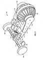
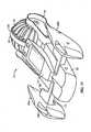
Figs. 1-11 a presently preferred first embodiment of a three wheeled toy vehicle (or simply "toy vehicle") generally designated at 10. Thetoy vehicle 10 is configured for use on land or in water. - With initial reference to
Figs. 1-3 , thetoy vehicle 10 includes achassis 12 with opposing major (top and bottom) sides 13a; 13b and opposing longitudinal (front and rear) ends 13c, 13d. Coupled with thechassis 12 are afront suspension 14 and arear suspension 16, and preferably three wheels. Acentral plane 12a extends longitudinally between the front and rear ends 13c, 13d and vertically through the top and bottom sides 13a, 13b, generally bisecting the ends 13c, 13d and the sides 13a, 13b. The wheels include a pair of steerable front wheels 18 (first and second wheels individually denoted at 18a, 18b) coupled with thechassis 12 proximal the first (front) end 13c so as to pivot with respect to thechassis 12 and steer thetoy vehicle 10. First andsecond wheels central plane 12a. Thevehicle 10 includes athird wheel 20 coupled with thechassis 12 proximal the second (rear) end 13d so as to span thecentral plane 12a. Thechassis 12 and front andrear suspensions protective body 22. Theprotective body 22 may include any shape, size or configuration that allows thetoy vehicle 10 to move as described below and is not limited to the embodiments shown inFigs. 1-2 and10-11 .Shocks 24 are shown as nonfunctional decorative additions to theprotective body 22 but may be coupled to thefront suspension 14 or a front bumper (not shown). - Referring to
Figs. 4 and5 , propulsion of thetoy vehicle 10 is preferably provided through thethird wheel 20 which is the only rear wheel. The rearthird wheel 20 is comprised of aninner core 26, left andright paddles elastomeric ring 30. Preferably, theinner core 26 is comprised of any material capable of absorbing impacts to thethird wheel 20 as well as being buoyant in water. Theinner core 26 maybe expanded polypropylene, foam, or air. Left andright paddles inner core 26. Preferably, thepaddles 28 are comprised of a flexible elastomeric material. A plurality equally spacedvanes 32 are be provided around both lateral sides of the left andright paddles paddles 28, to assist in propulsion of thetoy vehicle 10 in the water. Thevanes 32 are preferably curved and tapered toward the center of-thethird wheel 20 to provide a tubular shape to thethird wheel 20. Thevanes 32 are shown as being straight in the radial direction but may also have a tangential curve to further assist in steering and propelling thetoy vehicle 10. Thering 30 is positioned circumferentially around the center of thethird wheel 20 at the point where the left andright paddles ring 30 extends radially farther than thepaddles 28 from the center of thethird wheel 20 such that thering 30 contacts the land surface when on land and prevents thepaddles 28 from touching the land surface. However, thevanes 32 may touch the land surface when thethird wheel 20 is pivoted (as will be described) and they function as tire treads. Thethird wheel 20 is rotatably mounted to and driven through therear suspension 16. Thethird wheel 20 may be driven similarly to the rear wheel inU.S. Patent 6,854,547 B2, issued February 15, 2005 . - Referring to
Figs. 5 ,6 and10 , therear suspension 16 is preferably includes a U-shaped frame or similar structure, which is pivotably attached to thecentral chassis 12 to allow vertical movement of therear suspension 16 with respect to thechassis 12 about a generally horizontal rearwheel pivot axis 70 generally extending perpendicularly to thecentral plane 12a. Preferably, therear suspension 16 includes ahollow housing 34 that contains an internally mounted, preferably reversibleelectric motor 36. Agear train 38 can be provided to gear down the output of themotor 36. However, thethird wheel 20 may also be driven by any suitable means such one or more flexible members with pulleys or sprockets or a combination thereof or even an external friction wheel or gear on/in therear suspension 16 driven along the circumferential outer surface of thethird wheel 20. Therear suspension 16 preferably includes asuspension arm 40. Thesuspension arm 40 pivotably supports and surrounds thehollow housing 34,motor 36, and apivot axis 70 of theframe 17. Thesuspension arm 40 maybe connected to frame 17 by arear shock assembly 42. Thesuspension arm 40 and therear shock assembly 42 provide a rear damper and downward spring bias to theframe 17 with respect to thecentral chassis 12. Therear shock assembly 42 may be as simple as a coil spring extending between apin 40a on theextension arm 40 and abore 16a incross member 17c offrame 17. Therear shock assembly 42 may also be concealed by extending theassembly 42 farther into therear suspension 16. Also, theshock 42 could be replaced by a torsion spring in or on thehollow housing 34 or elsewhere between theframe 17 and thesuspension arm 40. - Referring to
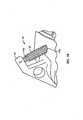
Figs. 6-9 , arear pivot shaft 44 preferably supports thesuspension arm 40 with therear wheel 20 andrear suspension 16 to pivot with respect to thechassis 12 along thepivot axis 44a.Axis 44a is normal to theaxis 70 of theframe 17 andthird wheel 20, and is coplanar with and lies in thecentral plane 12a, but is pitched away from the vertical direction of theplane 12a, preferably in a nearly horizontal or longitudinal direction of theplane 12a so as to effectively provide a roll axis for therear suspension 16 andrear wheel 20. Thesuspension arm 40 is nonrotatably attached to therear pivot shaft 44. Theshaft 44 is broken away inFigs. 6 and9 for clarity of other elements. Therear pivot shaft 44 is rotatable with respect to thechassis 12 and is to be driven by asteering servo 54, preferably operably coupled with thesteering servo 54 throughpinion 72 andgear 74 fixed toshaft 44 and meshed with thepinion 72. Alink 46 is nonrotatably attached to the front end of therear pivot shaft 44 most proximal thefront suspension 14 and operably connects therear pivot shaft 44 with thefront suspension 14. Thefront suspension 14 is connected to thecentral chassis 12 through afront pivot shaft 48 for rotation aboutpivot axis 48a central toshaft 48. Apin 50 extends up from thefront suspension 14 into thelink 46. Thelink 46 preferably includes twopin bars 52 generally parallel to therear pivot shaft 44 and spaced apart from one another. The free end of thepin 50 is inserted into thelink 46 and between the pin bars 52. Thepin 50 and link 46 may also be replaced with another rotary coupling such as a crank (not shown) rather than thepin 50 and link 46 to provide for the same offset rotary motion as described below. - A control circuit 100 (
Fig. 13 ) directs each of themotor 36 and thesteering servo 54. To propel thetoy vehicle 10, themotor 36 is activated. To steer thetoy vehicle 10, the steeringservo 54 is activated. The steeringservo 54, which is suggestedly is provided with a 2 to 1 gear reduction, rotates therear pivot shaft 44 up to about 30 degrees in either direction from a central or neutral, straight ahead position of the threewheels 18, 20. When therear pivot shaft 44 is pivoted, thesuspension arm 40 andyoke 17 of therear suspension 16 and thethird wheel 20 are all rotated (i.e. rolled) about the axis ofrotation 44a of therear pivot shaft 44 thereby pivoting such that the top and bottom ofthird wheel 20 tilt in the opposite direction towards either the left or right side of thetoy vehicle 10. Therear pivot shaft 44 is positioned at an angle sufficiently canted such that the axis of rotation ofthird wheel 20 is also tilted at a non-zero angle with respect to the longitudinal, (i.e. horizontal) direction and thereby causes thetoy vehicle 10 to turn when in motion.Axis 44a is tilted between the vertical and longitudinal directions so that when the front suspension pivots onaxis 44a, the suspension 14 (and the front wheels 18) also effectively roll about an imaginary longitudinal axis so as to keep all threewheels 18, 20 level. Tilting of thethird wheel 20 also helps to favor submersion of either the left orright paddle toy vehicle 10 to turn in water. As therear pivot shaft 44 moves, thelink 46 also pivots thefront suspension 14 and wheels 18 with respect to thechassis 12. As thelink 46 pivots, one of the twolink bars 52 urges thepin 50 in the direction of thelink 46 on rotatingpivot shaft 44. Movement of thepin 50 causes thefront suspension 14 to rotate about thefront suspension shaft 48 causing thetoy vehicle 10 to turn when in motion. This movement of thefront suspension 14 pivots the pair of front wheels 18 with respect to thechassis 12 and steer the front end 12c. This coupling causes the top ofthird wheel 20 to tilt to the side corresponding to the pivoted direction of the front wheels 18 allowing for improved turning capabilities in water and a smaller turning radius overall on land as well as water as the front wheels 18 also acts as steering fins or rudders on water. - Referring to
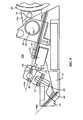
Figs. 7 and11 , the front wheels 18 are preferably hollow and sealed against fluid leakage to make the front end ofvehicle 10 buoyant and amphibious. Flotation, such as a buoyant material or air pockets may also be positioned on tabs 58 (SeeFigs. 3 and7 ), in theframe 17 ofrear suspension 16 and/or under thechassis 12. Preferably thetoy vehicle 10 is at least sufficiently buoyant so as to submerge less than half of thethird wheel 20. Left andright pontoons front wheels protective body 22 to be a sufficiently hollow to provide unrestricted rotation with therear suspension 16. - The steering
servo 54 and themotor 36 are conventionally powered by an on-board power source or supply 106 (Fig. 13 ), such as a battery or battery pack. Furthermore, it is preferred that thetoy vehicle 10 have conventional remote control elements, for example, mounted on acircuit board 101. Referring toFig. 13 , aconventional radio receiver 102,microprocessor 102b can be combined in a central circuit a 102 and used to control central appropriate motor control subcircuits 104(a), 104(b) to be remotely controlled by a user using a generally conventional remote control device ortransmitter 60 spaced from thetoy vehicle device 10. While remote control of thetoy vehicle 10 is preferred, it will be appreciated that the toy vehicle can be factory preprogrammed to perform a predetermined movement or series of movements or can be configured to be selectively programmed by a user to create such predetermined movement(s). Alternatively or in addition, thetoy vehicle 10 can be equipped with sensors, e.g., switches, proximity detectors, etc., that will control thetoy vehicle 10 to turn away from or reverse itself automatically from whatever direction it was moving if or when an obstacle is contacted or otherwise sensed. - Referring to
Figs. 1 ,12 and13 , a preferred remote control ortransmitter 60 may be comprised of a three piece housing having a central hub 62 aleft arm 64 and aright arm 66. The left andright arms central hub 62, or more preferably,central hub 62 and one arm (e.g. right arm 66) are fixedly connected together and the other arm (e.g. left arm 64) is rotatably attached to thepair 62/66. Thecentral hub 62 houses the electronics (not shown), which are themselves conventional, and relative motion ofleft arm 64 andright arm 66 from a neutral position, as seen inFigs. 1 and12 , steers thetoy vehicle 10. Anantenna 67, as shown inFigs. 1 and12 , extends from thecentral hub 62 for emitting a radio frequency.Arm pads Fig. 1 , may be positioned on the top side of theremote control 60 for forward and backward movement. Triggers (not shown in Figs.) may be positioned on the bottom side of theleft arm 64 and the right arm 65opposite pads remote control 60 and may be compressed or released to control other features, if provided. - Referring to
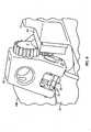
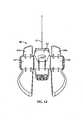
Figs. 14-16 , a second preferred embodiment of the toy vehicle indicated generally at 10' is shown, including like reference numerals to indicate like elements and a prime symbol (') distinguishing the reference numerals of the second preferred embodiment from the first preferred embodiment where differences are noted or apparent. The second preferred embodiment toy vehicle 10' is substantially similar to the first preferredembodiment toy vehicle 10. The second preferred embodiment of the toy vehicle 10' is three wheeled and is configured for use on land or in water. The toy vehicle 10' of also includes achassis 12' operably coupled with afront suspension 14' and a rear suspension 16', and threewheels 18a', 18b', 20' for steering and propulsion. A differently styled body 20' sits onchassis 12'. However, as seen inFig. 16 , the rear wheel 20' and power train of the second toy vehicle 10' differ from functionally those of thetoy vehicle 10 of the first preferred embodiment. - Referring to
Fig. 16 , preferably ahinge 125 supports the rear suspension 16' and the single rear wheel 20' from thechassis 12' and allows the rear suspension 16' and the single rear wheel 20' to pitch (i.e. move in a vertical direction about a transverse, horizontal axis) and roll (i.e. turn on an axis running substantially longitudinally through the vehicle 10') with respect to thechassis 12'. Preferably, drive motor 36' and a train of reduction gears 38' form adrive train 139 which is supported in adrive train housing 138, which is itself pivotally supported from thehinge 125 to pitch up and down with respect to thehinge 125. Acover 138a encloses thedrive train 139 within thedrive train housing 138. Preferably a shock assembly 42' is operatively connected between thehinge 125 and a top portion of thedrive train housing 138 or housing of rear suspension 16' to absorb excess or unwanted vertical motion of the rear suspension 16' and rear wheel 20'. Hinge 125 further permits drivetrain 139, rear suspension 16' and the rear wheel 20' to drop with respect tochassis 12' as those components are rolled for steering in a manner which will now be described. - Second toy vehicle 10' is again preferably steered through a servo 54'. More particularly, for example, a rear end of a
rotation shaft 126 is fixedly engaged with a front portion of thehinge 125 to support and roll thehinge 125 with thedrive train 139,housing 138, rear suspension 16' and wheel 20'with respect to thecentral chassis 12' about a central axis ofshaft 126, which is preferably co-planar with a central longitudinal andvertical plane 12a' of thetoy vehicle 10. Preferably, therotation shaft 126 passes through a servo output mechanism indicated generally at 140, which is itself driven by a servo 54'. Preferably,rotation shaft 126 is supported for driven rotation in ahousing 142 withcover 142a.Housing 142 is fixedly mounted on top of thechassis 12' with servo 54' so as to be powered by the servo 54'. Preferably, servo 54'powers output mechanism 140 though ascrew 158 driven by amotor 154 located with areduction gear train 156 in ahousing 152 withcover 152a. Preferably, screw 158 drives a reduction "steering"gear 169 which, in turn, drives a sector orpartial gear 171 fixed to therotation shaft 126 inhousing 142 to rotate theshaft 126. Preferably a manually operated,steering adjustment wheel 170 is provided, connected and preferably clutched to gear 169 to manually center the front andrear wheels 18, 20 and front andrear suspensions - In addition or in the alternative, a front portion of the
rotation shaft 126 preferably is operatively connected to thefront suspension 14' to steer thefront wheels 18a' 18b' at the same time it rolls the rear suspension 16' and wheel 20' side to side. Therotation shaft 126 thus is a steering coupling which operably couples and connects the front andrear suspension wheels 18, 20. Preferably a shaft 48' is fixedly mounted to a front portion of thecentral chassis 12' by abracket 127 to provide a pivot point at which thefront suspension 14' may rotate with respect to thecentral chassis 12'. Acrank 143 is operably connected to the front end ofrotation shaft 126 preferably through a clutch 145. Preferably,pin 143a on the distal end ofcrank 143 is operatively engaged with thesteering retainer 114 which, is fixedly engaged to thefront suspension 14'. Specifically,pin 143a is located between twoposts retainer 114. When thecrank 143 is caused to pivot or rotate as a result of rotation of therotation shaft 126, thepin 143a presses against one of theposts steering retainer 114 to cause thesteering retainer 114, and thus thefront suspension 14' withfront wheels 18a', 18b' to pivot about an at least partially vertical axis such that the toy vehicle 10' may be steered through thefront wheels 18a', 18b'. Thus, thefront suspension 14' is rotated with the pair offront wheels 18a', 18b' on the shaft 48' onbracket 127 with respect to thecentral chassis 12'. Likeshaft 48, shaft 48' is pitch forward so that thefront suspension 14' tilts (rolls) as it pivots (yaws) on shaft 48'. In the preferred steering configuration disclosed in vehicle 10', the twofront wheels 18a', 18b' of the toy vehicle 10' are mounted to the front suspension to remain coaxial and are turned (yawed) and pitched (rolled) by rotating and pitching thesuspension 14', while the rear suspension 16' and wheel 20' are simultaneously rolled to one side by the servo 54', which is operable connected to eachsuspension 14', 16' and all of the wheels 18', 20' through theservo output mechanism 140 androtation shaft 126, to steer the toy vehicle 10' at both ends of the toy vehicle 10' through the three wheels 18', 20'. - The degree of rotation of the
rotation shaft 126 can be controlled in various ways. Referring also toFig. 13 and16 , preferably, the front end ofrotation ann 126 is operably connected with anangular encoder 107 which may be of any suitable configuration to output one or more signals to on-board control circuitry 100. For example, therotation shaft 126 can carry one or more cams (not depicted) for closing switches or one or more electrical contacts or "wipers" 108 through which current can be passed to a set of stationary contacts, for example, on asmaller board 109 inencoder 107. In addition, if desired, a pair of trim adjustment levers (one on thehousing 140 and one on the shaft 126) can be provided to manually center theshaft 126 into a neutral (straight forward/backward) direction in addition to or in place ofadjustment wheel 170. - A drive motor 36' and reduction gear train 38' power the rear wheel 20'. Preferably, the motor 36' is operatively connected to a front portion of a drive shaft 177 and rotates or drives the drive shaft 177 through reduction gear train 38'. The drive shaft 177 is operatively positioned within the rear suspension 16' and preferably extends from the last gear in train 38' through the
cover 138a from the gear train 38' into arear suspension housing 116 and into the rear wheel 20'. Rotation of drive shaft 177 extending longitudinally through vehicle 10' is transferred to apower shaft 176 extending transversely though the rear wheel 20' andhousing 116. Drive shaft 177 is operably connected withpower shaft 176 through a suitable coupling, for example abevel gear 174 is located on a rear end of the drive shaft 177 meshing with abevel gear 175 operatively connected to apower shaft 176 to transfer power or rotational motion from the motor 36' to the rear wheel 20'. - Rear wheel 20' may be of any suitable construction but preferably, is rotatably mounted to a stationary cover ring or central hub 180, which is fixedly attached to the
rear suspension housing 116. Thepower shaft 176 extends axially through a central opening in the cover ring/central hub 180 to operatively connect with identical left and right rotation rings 122 of the rear wheel 20'. Each end of thepower shaft 176 is keyed into a central portion of eachrotation ring 122 such that eachrotation ring 122 rotates with rotation of thepower shaft 176 to provide power to the rear wheel 20'. Similar to thetoy vehicle 10 of the first preferred embodiment, the toy vehicle 10' of the second preferred embodiment includes a plurality of equally spaced vanes 32' on left andright paddles 28a', 28b' to assist in propulsion of the toy vehicle 10' in water or loose terrain. To further assist in traction, a second pair of left andright paddles right paddles 28', 28b'. For additional traction, particularly on pavement,elastomeric ring 30 preferably has been replaced by a first identical pair ofinner tires 130 and a second identical pair ofouter tires 132, which are located on either axial side of each of the left andright paddles 28', 28b'. Preferably too,identical reinforcement hubs 136 are provided to receive and support the left andright paddles 28', 28b' withouter tires 132 and to capture theinner tires 130 between themselves and the rotation rings 122. The resultinghalf wheel assemblies power shaft 142 by suitable means such as depictedidentical screw fasteners 135. - Further,
reinforcement hubs 136 are hollow and may be sealed or, more preferably, filled with a foam material to make the toy vehicle 10' more buoyant in water. Other sealed hollow chambers or foam filled spaces can be provided in vehicle 10' for further buoyancy. For example,separate pontoons fenders 22a', 22b' and spaces within the pontoons and/or other spaces in the fenders can be filled with foam as can any space between thechassis 12' and theprotective cover 22'. Additionally, arear fender 22c' is coupled via a bracket 22d' to thecover 22' and/orchassis 12' to cover the rear wheel 20' to prevent water from being thrown forward over the vehicle 10' during use. - The toy vehicle 10' of the second preferred embodiment includes a
battery door 105 to enclose a power supply within thecentral chassis 12'. Preferably, abattery pack 107 of other power supply provides power to the steering servo 54' and the motor 36'. Furthermore, it is preferred that the toy vehicle 10' have a conventional remote control electronics. For example, referring toFig. 13 , the toy vehicle 10' is controlled via radio (or other wireless) signals from theremote control transmitter 60. However, other types of controllers may be used including other types of wireless controllers (e.g., infrared, ultrasonic and/or voice-activated controllers) and even wired controllers and the like, withvehicle 10' or 10. - The toy vehicle 10' (and vehicle, 10) is provided with
control circuitry 100 preferably mounted on a conventional circuit board 101 (in phantom). For example,circuit board 101 can be disposed within thecentral chassis 12' or any other suitable location within the toy vehicle 10'. Referring toFig. 13 , thecontrol circuitry 100 preferably includes acontroller 102 having awireless signal receiver 102b and amicroprocessor 102a plus any necessary related elements such as memory. The steering servo 54' and the propulsion drive motor 36', are each respectively controlled by themicroprocessor 102a throughmotor control subcircuits microprocessor 102a, selectively couples the motor 36' and servo 54' with an electric power supply 106 (e.g. one or more disposable or rechargeable batteries or battery pack) in an appropriate direction. Preferably thepower supply 106 can provide a current of at least 1.0 to 12 amps (and bursts of 15 amps) when is fully charged. - In operation, the wireless
remote control transmitter 60 sends signals to the toy vehicle 10' that are received by thewireless signal receiver 102b viaantenna 103. Thewireless signal receiver 102b is in communication with and is operably connected with the servo 54' and the propulsion drive motor 36' through themicroprocessor 102a andsubcircuits - It will be appreciated by those skilled in the art that changes could be made to the embodiment described above without departing from the broad inventive concept thereof. For example, although the invention is described herein in terms of the preferred, three wheeled embodiment, the present invention could also comprise a vehicle having an additional rear wheel or only one front wheel. While the
front wheels 18a', 18b' are fixed to thefront suspension 14' thewheels 18a', 18b' could be pivotally supported by king pins or the like (not depicted) in a conventional manner on thechassis 12' and rotated side to side by a steering link or bar (not depicted), that could be moved side to side bycrank 143. However, it should be appreciated that pivoting the front wheels 18' with thefront fenders 22a', 22b' and pontoons 160 presents a greater area to the water than just the front wheels 18' to better steer the toy vehicle 10' in water. Furthermore, since the front suspension and wheels are pitched together while pivoting, both the front wheels remain level with one another as the rear wheel pitches. Thetoy vehicle 10, 10' can be constructed of, for example, plastic or any other suitable material such as metal or composite materials. Also, the dimensions of thetoy vehicle 10, 10' shown can be varied, for example making components of the toy vehicle smaller or larger relative to the other components. It should also be appreciated that some of the figures are more schematic than others. It is understood, therefore, that changes could be made to eitherembodiment 10, 10' of the toy vehicle described above without departing from the broad inventive concept thereof. It is understood, therefore, that this invention is not limited to the particular embodiment disclosed, but is intended to cover modifications within the scope of the present claims.
Claims (9)
- A motorized toy vehicle (10;10') comprising:a chassis (12; 12') with opposing, top and bottom sides (13a, 13b) and opposing, first and second longitudinal ends (13c, 13d) and a central plane (12a; 12a') extending in a vertical direction and a longitudinal direction through the chassis (12; 12') and at least generally bisecting the sides (13a, 13b) and ends (13c, 13d);first and second wheels (18a, 18b; 18a', 18b') coupled with the chassis (12; 12') proximal the first end (13c) so as to pivot with respect to the chassis (12; 12') and steer the first end, the first and second wheels (18a, 18b; 18a', 18b') being located on opposite sides of the central plane (12a; 12a');a third wheel (20; 20') coupled with the chassis (12; 12') proximal the second end (13d) so as to span the central plane (12a; 12a') and pivot with respect to the chassis (12; 12') at least along an axis (44a) located in the central plane (12a; 12a'), the axis being pitched away from the vertical direction and toward the longitudinal direction in the central plane (12a; 12a'); anda steering coupling operably connecting the first and second wheels (18a, 18b; 18a', 18b') with the third wheel (20, 20') to simultaneously pivot the first, second and third wheels (18a, 18b, 20; 18a', 18b', 20') with respect to the chassis (12, 12') in a selected direction, wherein a front suspension (14; 14') with the first and second wheels (18a, 18b; 18a', 18b') is connected to the chassis (12; 12') through a front pivot shaft (48, 48') for rotation about the front pivot shaft(48, 48');characterized in that the front suspension (14; 14') being coupled to the steering coupling and the first and second wheels (18a, 18b; 18a', 18b') of the front suspension (14; 14') remaining coaxial on the front suspension (14; 14') when the front suspension (14; 14') is pivoted about the front pivot shaft (48, 48').
- The toy vehicle of claim 1 further comprising a steering servo (54; 54') operably connected with the steering coupling to drive the steering coupling and pivot the first, second and third wheels (18a, 18b, 20; 18a', 18b', 20') and further comprising a power source (106) and control circuitry (102a) within the toy vehicle, the control circuitry including a controller with a wireless signal receiver (102) and a subcircuit (104a, 104b) operably controlled by the controller so as to selectively couple the steering servo (54; 54') with the power supply and thereby controllably selectively pivot the first, second and third wheels (18a, 18b, 20; 18a', 18b', 20') to controllably and selectively steer the toy vehicle (10; 10') by wireless signal.
- The toy vehicle of claim 1 wherein the third wheel (20; 20') is further coupled with the chassis (12; 12') so as to pivot with respect to the chassis (12; 12') about an axis at least generally perpendicular to the central plane (12a, 12a').
- The toy vehicle of claim 1 further comprising a drive motor (36; 36') operatively coupled with the third wheel (20; 20') to drive the third wheel (20; 20') to rotate about a central axis of the third wheel (20; 20') and propel the toy vehicle (10, 10').
- The toy vehicle of claim 4 wherein the third wheel (20; 20') and the drive motor (36, 36') are further coupled with the chassis (12; 12') so as to pivot with respect to the chassis (12; 12') about an axis at least generally perpendicular to the central plane and displaced in the central plane (12a; 12a') from the central axis of the third wheel assembly.
- The toy vehicle of claim 4 wherein the third wheel is an assembly and the toy vehicle (10; 10') further comprises a rear suspension (16; 16') including a stationary hub axially centered in the central plane (12a; 12a') and further comprising a drive coupling extending from the drive motor (36; 36') radially into the stationary hub (62).
- The toy vehicle of claim 6 wherein the third wheel (20) comprises a pair of half wheel assemblies located on opposite sides of the stationary hub and fixedly coupled together so as to be supported for rotation together on the stationary hub.
- The toy vehicle of claim 1 further comprising a motor (36; 36') operably coupled with the third wheel (20; 20') to propel the toy vehicle (10; 10') with the third wheel (20; 20'); and a rear suspension (16; 16') supporting the rear wheel (20; 20') for rotation about a central wheel axis and supporting the rear wheel (20; 20') and the motor to pivot along the axis located in the central plane (12a; 12a').
- The toy vehicle of claim 1 wherein the front suspension is mounted to pivot on an axis (44) pitched between longitudinal and vertical directions such that the front suspension (14; 14') and front wheels (18a, 18b; 18a', 18b') roll as well as yaw on the chassis (12; 12').
Applications Claiming Priority (3)
| Application Number | Priority Date | Filing Date | Title |
|---|---|---|---|
| US87074806P | 2006-12-19 | 2006-12-19 | |
| US95363607P | 2007-08-02 | 2007-08-02 | |
| PCT/US2007/083000WO2008079517A1 (en) | 2006-12-19 | 2007-10-30 | Three wheeled toy vehicle |
Publications (3)
| Publication Number | Publication Date |
|---|---|
| EP2097145A1 EP2097145A1 (en) | 2009-09-09 |
| EP2097145A4 EP2097145A4 (en) | 2012-01-25 |
| EP2097145B1true EP2097145B1 (en) | 2014-02-26 |
Family
ID=39562877
Family Applications (1)
| Application Number | Title | Priority Date | Filing Date |
|---|---|---|---|
| EP07863655.2ANot-in-forceEP2097145B1 (en) | 2006-12-19 | 2007-10-30 | Three wheeled toy vehicle |
Country Status (6)
| Country | Link |
|---|---|
| US (1) | US8430713B2 (en) |
| EP (1) | EP2097145B1 (en) |
| CN (1) | CN101557864B (en) |
| CA (1) | CA2669934A1 (en) |
| MX (1) | MX2009006715A (en) |
| WO (1) | WO2008079517A1 (en) |
Families Citing this family (9)
| Publication number | Priority date | Publication date | Assignee | Title |
|---|---|---|---|---|
| US9049293B2 (en)* | 2008-05-06 | 2015-06-02 | International Business Machines Corporation | Performing proximity based routing of a phone call |
| US8280415B2 (en) | 2008-05-06 | 2012-10-02 | International Business Machines Corporation | Performing caller based routing of a phone call |
| DE102012201132A1 (en)* | 2012-01-26 | 2013-08-01 | Bruder Spielwaren Gmbh + Co. Kg | clutch |
| CN105561597A (en)* | 2016-01-17 | 2016-05-11 | 马洪斌 | Recreation chariot operated in totally-closed cabin |
| US10946922B2 (en)* | 2017-02-16 | 2021-03-16 | Mattel, Inc. | Ride-on toy vehicle configured to tilt and drift |
| US10898845B2 (en)* | 2017-07-31 | 2021-01-26 | Fanca Technologies Pty Ltd. | Mobile dust extraction device |
| EP3909657B1 (en)* | 2020-05-14 | 2022-06-29 | Hua Xue | Model vehicle for land and water operation |
| WO2022132829A1 (en)* | 2020-12-14 | 2022-06-23 | Jakks Pacific, Inc. | Rc vehicle with convertible wheel having expandable and retractable blades |
| CN113559527A (en)* | 2021-07-23 | 2021-10-29 | 东莞龙昌数码科技有限公司 | Claw-wheel toy car |
Family Cites Families (35)
| Publication number | Priority date | Publication date | Assignee | Title |
|---|---|---|---|---|
| US3048447A (en)* | 1960-08-05 | 1962-08-07 | Ny Lint Tool & Mfg Co | Toy white side wall tire |
| US3746118A (en)* | 1971-07-15 | 1973-07-17 | E Altorfer | Three-wheeled vehicle with passenger banking |
| US3733739A (en)* | 1971-12-30 | 1973-05-22 | Marvin Glass & Associates | Motor operated toy vehicle |
| CA981717A (en)* | 1974-09-13 | 1976-01-13 | David W. Smith | Three wheeled vehicle |
| US4132435A (en)* | 1977-06-30 | 1979-01-02 | Ken Wilson Departures, Inc. | Steerable wheeled vehicle |
| FR2420469A1 (en)* | 1978-03-23 | 1979-10-19 | Janin Pierre | SELF-PROPELLED VEHICLE WITH RANDOM TRAIL |
| JPS5918083A (en)* | 1982-07-20 | 1984-01-30 | ヤマハ発動機株式会社 | Small-sized snowmobile |
| US4526392A (en)* | 1982-11-15 | 1985-07-02 | Berkstresser David E | Recumbent velocipede |
| US4703824A (en)* | 1983-05-20 | 1987-11-03 | Honda Giken Kogyo Kabushiki Kaisha | Three-wheeled vehicle |
| EP0247093A4 (en) | 1985-11-15 | 1988-04-06 | Philip Ronald James | Self stabilizing cambering vehicle. |
| US4693696A (en)* | 1986-01-27 | 1987-09-15 | Buck Gordon H | Inflated balloon tire for toy vehicles |
| US4832651A (en)* | 1987-03-06 | 1989-05-23 | Buck Gordon H | Inflated balloon tire for toy vehicles |
| US4903857A (en)* | 1988-10-18 | 1990-02-27 | Klopfenstein King L | Leaning vehicle with centrifugal force compensation |
| JPH0649346Y2 (en)* | 1989-02-01 | 1994-12-14 | 株式会社グリーン | Radio-controlled motorcycle toys |
| US4993733A (en)* | 1989-02-21 | 1991-02-19 | Keith Eilers | Three wheeled recumbent cycle |
| DE4135585A1 (en) | 1991-10-29 | 1993-05-06 | Richard 6800 Mannheim De Jelke | Motor vehicle with three or more wheels - has entry door and ability to lean over when negotiating curves like two-wheeled vehicle |
| DE19513649A1 (en) | 1995-04-11 | 1996-10-17 | Kurt Dr Med Hoppe | Three-wheeled vehicle for use like bicycle or motorcycle |
| GB2328621A (en) | 1997-08-18 | 1999-03-03 | Mattel Inc | Toy vehicle |
| US6551169B2 (en)* | 1999-08-06 | 2003-04-22 | Mattel, Inc. | Toy vehicle with rotating front end |
| US6464030B1 (en)* | 2001-04-17 | 2002-10-15 | Corbin Pacific, Inc. | Three wheel steering assembly |
| US6540583B1 (en)* | 2001-10-19 | 2003-04-01 | Michael G. Hoeting | Toy vehicle |
| US6648722B2 (en)* | 2001-10-26 | 2003-11-18 | The Obb, Llc | Three wheeled wireless controlled toy stunt vehicle |
| GB2382334B (en) | 2001-11-24 | 2004-05-05 | Rodney John Davey | Tiltable vehicle |
| AU2003206529A1 (en)* | 2002-02-22 | 2003-09-09 | Bombardier Recreational Products Inc. | Components for a three-wheeled vehicle to permit leaning of the driver |
| US6692333B2 (en)* | 2002-05-31 | 2004-02-17 | The Obb, Llc | Toy vehicle |
| NL1021195C2 (en)* | 2002-07-31 | 2004-02-03 | Brinks Westmaas Bv | Tilt vehicle. |
| FR2846623A1 (en) | 2002-10-30 | 2004-05-07 | Michel Jacques Arias | Three of four wheeled motor vehicle enabling user to sit in a formula 1 racing type cockpit while being able to lean into a bend like a motorcycle, includes two relatively inclinable chassis parts |
| WO2004040996A2 (en)* | 2002-10-31 | 2004-05-21 | Mattel, Inc. | Toy vehicle |
| DE20320343U1 (en)* | 2002-11-01 | 2004-04-22 | The Obb, Llc | Toy vehicle with movable body components |
| JP4015534B2 (en) | 2002-11-15 | 2007-11-28 | 京商株式会社 | Radio-controlled motorcycle toy |
| WO2005030559A1 (en)* | 2003-05-02 | 2005-04-07 | James Christopher Dower | A three wheeled vehicle with tilting mechanism |
| DE602004020786D1 (en)* | 2003-11-12 | 2009-06-04 | Mattel Inc | SPINDLE DRIVEN VEHICLE |
| US20060009119A1 (en)* | 2004-07-09 | 2006-01-12 | Bang Zoom Design Ltd. | Toy vehicle with stabilized front wheel |
| US8025551B2 (en)* | 2006-09-20 | 2011-09-27 | Mattel, Inc. | Multi-mode three wheeled toy vehicle |
| US20090098799A1 (en)* | 2007-10-10 | 2009-04-16 | Vladmir Leonov | Articulated, angle-steering, and tilting three-wheeled toy vehicle |
- 2007
- 2007-10-30EPEP07863655.2Apatent/EP2097145B1/ennot_activeNot-in-force
- 2007-10-30WOPCT/US2007/083000patent/WO2008079517A1/enactiveApplication Filing
- 2007-10-30MXMX2009006715Apatent/MX2009006715A/enactiveIP Right Grant
- 2007-10-30CNCN2007800464856Apatent/CN101557864B/ennot_activeExpired - Fee Related
- 2007-10-30CACA002669934Apatent/CA2669934A1/ennot_activeAbandoned
- 2009
- 2009-06-19USUS12/487,779patent/US8430713B2/ennot_activeExpired - Fee Related
Also Published As
| Publication number | Publication date |
|---|---|
| US8430713B2 (en) | 2013-04-30 |
| CN101557864A (en) | 2009-10-14 |
| US20090280718A1 (en) | 2009-11-12 |
| HK1133847A1 (en) | 2010-04-09 |
| EP2097145A4 (en) | 2012-01-25 |
| MX2009006715A (en) | 2009-06-30 |
| WO2008079517A1 (en) | 2008-07-03 |
| CN101557864B (en) | 2011-05-18 |
| CA2669934A1 (en) | 2008-07-03 |
| EP2097145A1 (en) | 2009-09-09 |
Similar Documents
| Publication | Publication Date | Title |
|---|---|---|
| EP2097145B1 (en) | Three wheeled toy vehicle | |
| EP1670680B1 (en) | Screw drive vehicle | |
| EP1954365B1 (en) | Toy vehicle | |
| US6939197B1 (en) | Toy vehicle with enhanced jumping capability | |
| US6551169B2 (en) | Toy vehicle with rotating front end | |
| US5882241A (en) | Toy vehicle with movable front end | |
| US6475059B2 (en) | Single driving wheel remote control toy vehicle | |
| WO2007130617A2 (en) | Transformable toy vehicle | |
| CN1476341A (en) | Three-wheeled wireless controlld toy stunt vehicle | |
| JPS62157872A (en) | Slender car | |
| US20090098799A1 (en) | Articulated, angle-steering, and tilting three-wheeled toy vehicle | |
| JP2000325671A (en) | Remote control car | |
| HK1133847B (en) | Three wheeled toy vehicle | |
| US20230118786A1 (en) | Toy vehicle suspension and wheels | |
| US20060211332A1 (en) | Toy vehicle with big wheel | |
| WO2000007682A1 (en) | Toy vehicle with rotating front end | |
| AU7279198A (en) | Remotely controlled toy vehicle with common castor front steering | |
| EP1827639A2 (en) | Toy vehicle with big wheel | |
| MXPA99008206A (en) | Remotely controlled toy vehicle with common castor front steering | |
| HK1096890B (en) | Toy vehicle |
Legal Events
| Date | Code | Title | Description |
|---|---|---|---|
| PUAI | Public reference made under article 153(3) epc to a published international application that has entered the european phase | Free format text:ORIGINAL CODE: 0009012 | |
| 17P | Request for examination filed | Effective date:20090615 | |
| AK | Designated contracting states | Kind code of ref document:A1 Designated state(s):AT BE BG CH CY CZ DE DK EE ES FI FR GB GR HU IE IS IT LI LT LU LV MC MT NL PL PT RO SE SI SK TR | |
| DAX | Request for extension of the european patent (deleted) | ||
| A4 | Supplementary search report drawn up and despatched | Effective date:20111223 | |
| RIC1 | Information provided on ipc code assigned before grant | Ipc:A63H 17/00 20060101AFI20111219BHEP | |
| GRAP | Despatch of communication of intention to grant a patent | Free format text:ORIGINAL CODE: EPIDOSNIGR1 | |
| INTG | Intention to grant announced | Effective date:20130919 | |
| GRAS | Grant fee paid | Free format text:ORIGINAL CODE: EPIDOSNIGR3 | |
| GRAA | (expected) grant | Free format text:ORIGINAL CODE: 0009210 | |
| AK | Designated contracting states | Kind code of ref document:B1 Designated state(s):AT BE BG CH CY CZ DE DK EE ES FI FR GB GR HU IE IS IT LI LT LU LV MC MT NL PL PT RO SE SI SK TR | |
| REG | Reference to a national code | Ref country code:GB Ref legal event code:FG4D | |
| REG | Reference to a national code | Ref country code:CH Ref legal event code:EP | |
| REG | Reference to a national code | Ref country code:AT Ref legal event code:REF Ref document number:653209 Country of ref document:AT Kind code of ref document:T Effective date:20140315 | |
| REG | Reference to a national code | Ref country code:DE Ref legal event code:R082 Ref document number:602007035288 Country of ref document:DE Representative=s name:WEICKMANN & WEICKMANN PATENTANWAELTE - RECHTSA, DE Ref country code:DE Ref legal event code:R082 Ref document number:602007035288 Country of ref document:DE Representative=s name:WEICKMANN & WEICKMANN, DE Ref country code:DE Ref legal event code:R082 Ref document number:602007035288 Country of ref document:DE Representative=s name:HANSMANN & VOGESER, DE Ref country code:DE Ref legal event code:R082 Ref document number:602007035288 Country of ref document:DE Representative=s name:PATENTANWAELTE WEICKMANN & WEICKMANN, DE Ref country code:DE Ref legal event code:R082 Ref document number:602007035288 Country of ref document:DE Representative=s name:WEICKMANN & WEICKMANN PATENT- UND RECHTSANWAEL, DE | |
| REG | Reference to a national code | Ref country code:IE Ref legal event code:FG4D | |
| REG | Reference to a national code | Ref country code:DE Ref legal event code:R096 Ref document number:602007035288 Country of ref document:DE Effective date:20140410 | |
| REG | Reference to a national code | Ref country code:NL Ref legal event code:VDEP Effective date:20140226 | |
| REG | Reference to a national code | Ref country code:AT Ref legal event code:MK05 Ref document number:653209 Country of ref document:AT Kind code of ref document:T Effective date:20140226 | |
| REG | Reference to a national code | Ref country code:LT Ref legal event code:MG4D | |
| PG25 | Lapsed in a contracting state [announced via postgrant information from national office to epo] | Ref country code:LT Free format text:LAPSE BECAUSE OF FAILURE TO SUBMIT A TRANSLATION OF THE DESCRIPTION OR TO PAY THE FEE WITHIN THE PRESCRIBED TIME-LIMIT Effective date:20140226 Ref country code:IS Free format text:LAPSE BECAUSE OF FAILURE TO SUBMIT A TRANSLATION OF THE DESCRIPTION OR TO PAY THE FEE WITHIN THE PRESCRIBED TIME-LIMIT Effective date:20140626 | |
| PG25 | Lapsed in a contracting state [announced via postgrant information from national office to epo] | Ref country code:CY Free format text:LAPSE BECAUSE OF FAILURE TO SUBMIT A TRANSLATION OF THE DESCRIPTION OR TO PAY THE FEE WITHIN THE PRESCRIBED TIME-LIMIT Effective date:20140226 Ref country code:SE Free format text:LAPSE BECAUSE OF FAILURE TO SUBMIT A TRANSLATION OF THE DESCRIPTION OR TO PAY THE FEE WITHIN THE PRESCRIBED TIME-LIMIT Effective date:20140226 Ref country code:FI Free format text:LAPSE BECAUSE OF FAILURE TO SUBMIT A TRANSLATION OF THE DESCRIPTION OR TO PAY THE FEE WITHIN THE PRESCRIBED TIME-LIMIT Effective date:20140226 Ref country code:AT Free format text:LAPSE BECAUSE OF FAILURE TO SUBMIT A TRANSLATION OF THE DESCRIPTION OR TO PAY THE FEE WITHIN THE PRESCRIBED TIME-LIMIT Effective date:20140226 Ref country code:NL Free format text:LAPSE BECAUSE OF FAILURE TO SUBMIT A TRANSLATION OF THE DESCRIPTION OR TO PAY THE FEE WITHIN THE PRESCRIBED TIME-LIMIT Effective date:20140226 Ref country code:PT Free format text:LAPSE BECAUSE OF FAILURE TO SUBMIT A TRANSLATION OF THE DESCRIPTION OR TO PAY THE FEE WITHIN THE PRESCRIBED TIME-LIMIT Effective date:20140626 | |
| PG25 | Lapsed in a contracting state [announced via postgrant information from national office to epo] | Ref country code:BE Free format text:LAPSE BECAUSE OF FAILURE TO SUBMIT A TRANSLATION OF THE DESCRIPTION OR TO PAY THE FEE WITHIN THE PRESCRIBED TIME-LIMIT Effective date:20140226 Ref country code:LV Free format text:LAPSE BECAUSE OF FAILURE TO SUBMIT A TRANSLATION OF THE DESCRIPTION OR TO PAY THE FEE WITHIN THE PRESCRIBED TIME-LIMIT Effective date:20140226 | |
| PG25 | Lapsed in a contracting state [announced via postgrant information from national office to epo] | Ref country code:CZ Free format text:LAPSE BECAUSE OF FAILURE TO SUBMIT A TRANSLATION OF THE DESCRIPTION OR TO PAY THE FEE WITHIN THE PRESCRIBED TIME-LIMIT Effective date:20140226 Ref country code:EE Free format text:LAPSE BECAUSE OF FAILURE TO SUBMIT A TRANSLATION OF THE DESCRIPTION OR TO PAY THE FEE WITHIN THE PRESCRIBED TIME-LIMIT Effective date:20140226 Ref country code:DK Free format text:LAPSE BECAUSE OF FAILURE TO SUBMIT A TRANSLATION OF THE DESCRIPTION OR TO PAY THE FEE WITHIN THE PRESCRIBED TIME-LIMIT Effective date:20140226 Ref country code:RO Free format text:LAPSE BECAUSE OF FAILURE TO SUBMIT A TRANSLATION OF THE DESCRIPTION OR TO PAY THE FEE WITHIN THE PRESCRIBED TIME-LIMIT Effective date:20140226 | |
| REG | Reference to a national code | Ref country code:DE Ref legal event code:R097 Ref document number:602007035288 Country of ref document:DE | |
| PG25 | Lapsed in a contracting state [announced via postgrant information from national office to epo] | Ref country code:SK Free format text:LAPSE BECAUSE OF FAILURE TO SUBMIT A TRANSLATION OF THE DESCRIPTION OR TO PAY THE FEE WITHIN THE PRESCRIBED TIME-LIMIT Effective date:20140226 Ref country code:ES Free format text:LAPSE BECAUSE OF FAILURE TO SUBMIT A TRANSLATION OF THE DESCRIPTION OR TO PAY THE FEE WITHIN THE PRESCRIBED TIME-LIMIT Effective date:20140226 Ref country code:PL Free format text:LAPSE BECAUSE OF FAILURE TO SUBMIT A TRANSLATION OF THE DESCRIPTION OR TO PAY THE FEE WITHIN THE PRESCRIBED TIME-LIMIT Effective date:20140226 | |
| PLBE | No opposition filed within time limit | Free format text:ORIGINAL CODE: 0009261 | |
| STAA | Information on the status of an ep patent application or granted ep patent | Free format text:STATUS: NO OPPOSITION FILED WITHIN TIME LIMIT | |
| PGFP | Annual fee paid to national office [announced via postgrant information from national office to epo] | Ref country code:GB Payment date:20141027 Year of fee payment:8 Ref country code:FR Payment date:20141017 Year of fee payment:8 Ref country code:DE Payment date:20141029 Year of fee payment:8 | |
| 26N | No opposition filed | Effective date:20141127 | |
| REG | Reference to a national code | Ref country code:DE Ref legal event code:R097 Ref document number:602007035288 Country of ref document:DE Effective date:20141127 | |
| PG25 | Lapsed in a contracting state [announced via postgrant information from national office to epo] | Ref country code:IT Free format text:LAPSE BECAUSE OF FAILURE TO SUBMIT A TRANSLATION OF THE DESCRIPTION OR TO PAY THE FEE WITHIN THE PRESCRIBED TIME-LIMIT Effective date:20140226 | |
| REG | Reference to a national code | Ref country code:DE Ref legal event code:R082 Ref document number:602007035288 Country of ref document:DE Representative=s name:PATENTANWAELTE WEICKMANN & WEICKMANN, DE Ref country code:DE Ref legal event code:R082 Ref document number:602007035288 Country of ref document:DE Representative=s name:WEICKMANN & WEICKMANN PATENTANWAELTE - RECHTSA, DE Ref country code:DE Ref legal event code:R082 Ref document number:602007035288 Country of ref document:DE Representative=s name:WEICKMANN & WEICKMANN PATENT- UND RECHTSANWAEL, DE | |
| PG25 | Lapsed in a contracting state [announced via postgrant information from national office to epo] | Ref country code:SI Free format text:LAPSE BECAUSE OF FAILURE TO SUBMIT A TRANSLATION OF THE DESCRIPTION OR TO PAY THE FEE WITHIN THE PRESCRIBED TIME-LIMIT Effective date:20140226 Ref country code:MC Free format text:LAPSE BECAUSE OF FAILURE TO SUBMIT A TRANSLATION OF THE DESCRIPTION OR TO PAY THE FEE WITHIN THE PRESCRIBED TIME-LIMIT Effective date:20140226 Ref country code:LU Free format text:LAPSE BECAUSE OF FAILURE TO SUBMIT A TRANSLATION OF THE DESCRIPTION OR TO PAY THE FEE WITHIN THE PRESCRIBED TIME-LIMIT Effective date:20141030 | |
| REG | Reference to a national code | Ref country code:CH Ref legal event code:PL | |
| REG | Reference to a national code | Ref country code:IE Ref legal event code:MM4A | |
| PG25 | Lapsed in a contracting state [announced via postgrant information from national office to epo] | Ref country code:LI Free format text:LAPSE BECAUSE OF NON-PAYMENT OF DUE FEES Effective date:20141031 Ref country code:CH Free format text:LAPSE BECAUSE OF NON-PAYMENT OF DUE FEES Effective date:20141031 | |
| PG25 | Lapsed in a contracting state [announced via postgrant information from national office to epo] | Ref country code:IE Free format text:LAPSE BECAUSE OF NON-PAYMENT OF DUE FEES Effective date:20141030 | |
| REG | Reference to a national code | Ref country code:DE Ref legal event code:R119 Ref document number:602007035288 Country of ref document:DE | |
| PG25 | Lapsed in a contracting state [announced via postgrant information from national office to epo] | Ref country code:BG Free format text:LAPSE BECAUSE OF FAILURE TO SUBMIT A TRANSLATION OF THE DESCRIPTION OR TO PAY THE FEE WITHIN THE PRESCRIBED TIME-LIMIT Effective date:20140226 | |
| GBPC | Gb: european patent ceased through non-payment of renewal fee | Effective date:20151030 | |
| PG25 | Lapsed in a contracting state [announced via postgrant information from national office to epo] | Ref country code:GR Free format text:LAPSE BECAUSE OF FAILURE TO SUBMIT A TRANSLATION OF THE DESCRIPTION OR TO PAY THE FEE WITHIN THE PRESCRIBED TIME-LIMIT Effective date:20140527 | |
| PG25 | Lapsed in a contracting state [announced via postgrant information from national office to epo] | Ref country code:GB Free format text:LAPSE BECAUSE OF NON-PAYMENT OF DUE FEES Effective date:20151030 Ref country code:TR Free format text:LAPSE BECAUSE OF FAILURE TO SUBMIT A TRANSLATION OF THE DESCRIPTION OR TO PAY THE FEE WITHIN THE PRESCRIBED TIME-LIMIT Effective date:20140226 Ref country code:HU Free format text:LAPSE BECAUSE OF FAILURE TO SUBMIT A TRANSLATION OF THE DESCRIPTION OR TO PAY THE FEE WITHIN THE PRESCRIBED TIME-LIMIT; INVALID AB INITIO Effective date:20071030 Ref country code:DE Free format text:LAPSE BECAUSE OF NON-PAYMENT OF DUE FEES Effective date:20160503 Ref country code:MT Free format text:LAPSE BECAUSE OF FAILURE TO SUBMIT A TRANSLATION OF THE DESCRIPTION OR TO PAY THE FEE WITHIN THE PRESCRIBED TIME-LIMIT Effective date:20140226 | |
| REG | Reference to a national code | Ref country code:FR Ref legal event code:ST Effective date:20160630 | |
| PG25 | Lapsed in a contracting state [announced via postgrant information from national office to epo] | Ref country code:FR Free format text:LAPSE BECAUSE OF NON-PAYMENT OF DUE FEES Effective date:20151102 |