EP2096191B1 - Ethylene-tetrafluoroethylene copolymer molded product and method for producing the same - Google Patents
Ethylene-tetrafluoroethylene copolymer molded product and method for producing the sameDownload PDFInfo
- Publication number
- EP2096191B1 EP2096191B1EP07806286.6AEP07806286AEP2096191B1EP 2096191 B1EP2096191 B1EP 2096191B1EP 07806286 AEP07806286 AEP 07806286AEP 2096191 B1EP2096191 B1EP 2096191B1
- Authority
- EP
- European Patent Office
- Prior art keywords
- silicon oxide
- oxide film
- film
- ethylene
- substrate
- Prior art date
- Legal status (The legal status is an assumption and is not a legal conclusion. Google has not performed a legal analysis and makes no representation as to the accuracy of the status listed.)
- Not-in-force
Links
Images
Classifications
- C—CHEMISTRY; METALLURGY
- C23—COATING METALLIC MATERIAL; COATING MATERIAL WITH METALLIC MATERIAL; CHEMICAL SURFACE TREATMENT; DIFFUSION TREATMENT OF METALLIC MATERIAL; COATING BY VACUUM EVAPORATION, BY SPUTTERING, BY ION IMPLANTATION OR BY CHEMICAL VAPOUR DEPOSITION, IN GENERAL; INHIBITING CORROSION OF METALLIC MATERIAL OR INCRUSTATION IN GENERAL
- C23C—COATING METALLIC MATERIAL; COATING MATERIAL WITH METALLIC MATERIAL; SURFACE TREATMENT OF METALLIC MATERIAL BY DIFFUSION INTO THE SURFACE, BY CHEMICAL CONVERSION OR SUBSTITUTION; COATING BY VACUUM EVAPORATION, BY SPUTTERING, BY ION IMPLANTATION OR BY CHEMICAL VAPOUR DEPOSITION, IN GENERAL
- C23C16/00—Chemical coating by decomposition of gaseous compounds, without leaving reaction products of surface material in the coating, i.e. chemical vapour deposition [CVD] processes
- C23C16/22—Chemical coating by decomposition of gaseous compounds, without leaving reaction products of surface material in the coating, i.e. chemical vapour deposition [CVD] processes characterised by the deposition of inorganic material, other than metallic material
- C23C16/30—Deposition of compounds, mixtures or solid solutions, e.g. borides, carbides, nitrides
- C23C16/40—Oxides
- C23C16/401—Oxides containing silicon
- C—CHEMISTRY; METALLURGY
- C08—ORGANIC MACROMOLECULAR COMPOUNDS; THEIR PREPARATION OR CHEMICAL WORKING-UP; COMPOSITIONS BASED THEREON
- C08J—WORKING-UP; GENERAL PROCESSES OF COMPOUNDING; AFTER-TREATMENT NOT COVERED BY SUBCLASSES C08B, C08C, C08F, C08G or C08H
- C08J7/00—Chemical treatment or coating of shaped articles made of macromolecular substances
- C08J7/04—Coating
- C08J7/043—Improving the adhesiveness of the coatings per se, e.g. forming primers
- C—CHEMISTRY; METALLURGY
- C08—ORGANIC MACROMOLECULAR COMPOUNDS; THEIR PREPARATION OR CHEMICAL WORKING-UP; COMPOSITIONS BASED THEREON
- C08J—WORKING-UP; GENERAL PROCESSES OF COMPOUNDING; AFTER-TREATMENT NOT COVERED BY SUBCLASSES C08B, C08C, C08F, C08G or C08H
- C08J7/00—Chemical treatment or coating of shaped articles made of macromolecular substances
- C08J7/04—Coating
- C08J7/046—Forming abrasion-resistant coatings; Forming surface-hardening coatings
- C—CHEMISTRY; METALLURGY
- C08—ORGANIC MACROMOLECULAR COMPOUNDS; THEIR PREPARATION OR CHEMICAL WORKING-UP; COMPOSITIONS BASED THEREON
- C08J—WORKING-UP; GENERAL PROCESSES OF COMPOUNDING; AFTER-TREATMENT NOT COVERED BY SUBCLASSES C08B, C08C, C08F, C08G or C08H
- C08J7/00—Chemical treatment or coating of shaped articles made of macromolecular substances
- C08J7/04—Coating
- C08J7/056—Forming hydrophilic coatings
- C—CHEMISTRY; METALLURGY
- C08—ORGANIC MACROMOLECULAR COMPOUNDS; THEIR PREPARATION OR CHEMICAL WORKING-UP; COMPOSITIONS BASED THEREON
- C08J—WORKING-UP; GENERAL PROCESSES OF COMPOUNDING; AFTER-TREATMENT NOT COVERED BY SUBCLASSES C08B, C08C, C08F, C08G or C08H
- C08J7/00—Chemical treatment or coating of shaped articles made of macromolecular substances
- C08J7/04—Coating
- C08J7/06—Coating with compositions not containing macromolecular substances
- C—CHEMISTRY; METALLURGY
- C23—COATING METALLIC MATERIAL; COATING MATERIAL WITH METALLIC MATERIAL; CHEMICAL SURFACE TREATMENT; DIFFUSION TREATMENT OF METALLIC MATERIAL; COATING BY VACUUM EVAPORATION, BY SPUTTERING, BY ION IMPLANTATION OR BY CHEMICAL VAPOUR DEPOSITION, IN GENERAL; INHIBITING CORROSION OF METALLIC MATERIAL OR INCRUSTATION IN GENERAL
- C23C—COATING METALLIC MATERIAL; COATING MATERIAL WITH METALLIC MATERIAL; SURFACE TREATMENT OF METALLIC MATERIAL BY DIFFUSION INTO THE SURFACE, BY CHEMICAL CONVERSION OR SUBSTITUTION; COATING BY VACUUM EVAPORATION, BY SPUTTERING, BY ION IMPLANTATION OR BY CHEMICAL VAPOUR DEPOSITION, IN GENERAL
- C23C16/00—Chemical coating by decomposition of gaseous compounds, without leaving reaction products of surface material in the coating, i.e. chemical vapour deposition [CVD] processes
- C23C16/44—Chemical coating by decomposition of gaseous compounds, without leaving reaction products of surface material in the coating, i.e. chemical vapour deposition [CVD] processes characterised by the method of coating
- C23C16/50—Chemical coating by decomposition of gaseous compounds, without leaving reaction products of surface material in the coating, i.e. chemical vapour deposition [CVD] processes characterised by the method of coating using electric discharges
- C23C16/505—Chemical coating by decomposition of gaseous compounds, without leaving reaction products of surface material in the coating, i.e. chemical vapour deposition [CVD] processes characterised by the method of coating using electric discharges using radio frequency discharges
- C23C16/509—Chemical coating by decomposition of gaseous compounds, without leaving reaction products of surface material in the coating, i.e. chemical vapour deposition [CVD] processes characterised by the method of coating using electric discharges using radio frequency discharges using internal electrodes
- C—CHEMISTRY; METALLURGY
- C08—ORGANIC MACROMOLECULAR COMPOUNDS; THEIR PREPARATION OR CHEMICAL WORKING-UP; COMPOSITIONS BASED THEREON
- C08J—WORKING-UP; GENERAL PROCESSES OF COMPOUNDING; AFTER-TREATMENT NOT COVERED BY SUBCLASSES C08B, C08C, C08F, C08G or C08H
- C08J2327/00—Characterised by the use of homopolymers or copolymers of compounds having one or more unsaturated aliphatic radicals, each having only one carbon-to-carbon double bond, and at least one being terminated by a halogen; Derivatives of such polymers
- C08J2327/02—Characterised by the use of homopolymers or copolymers of compounds having one or more unsaturated aliphatic radicals, each having only one carbon-to-carbon double bond, and at least one being terminated by a halogen; Derivatives of such polymers not modified by chemical after-treatment
- C08J2327/12—Characterised by the use of homopolymers or copolymers of compounds having one or more unsaturated aliphatic radicals, each having only one carbon-to-carbon double bond, and at least one being terminated by a halogen; Derivatives of such polymers not modified by chemical after-treatment containing fluorine atoms
- C08J2327/18—Homopolymers or copolymers of tetrafluoroethylene
Definitions
- the present inventionrelates to an ethylene/tetrafluoroethylene copolymer molded product and a method for its production
- ETFE copolymerAn ethylene/tetrafluoroethylene copolymer (hereinafter referred to as ETFE copolymer) is a polymer having weather resistance and chemical resistance inherent to a fluoropolymer and flexibility inherent to a hydrocarbon polymer. Further, the ETFE copolymer is a material having a low refractive index, whereby reflection of light is little, and light transmittance is high.
- the ETFE copolymer molded productis widely used as a material for e.g. an exterior film for system kitchens, a surface film of a white board for marker pens, a mold release film, an outdoor film, a member for displays or a protective film for solar batteries.
- the ETFE copolymeris a fluoropolymer
- the surface energyis low. Therefore, the contact angle to water (hereinafter referred to as water contact angle) is at least 100°. Accordingly, water droplets tend to be formed on the surface.
- the filmis likely to be fogged with water droplets condensed on the surface of the ETFE copolymer film, or water droplets may drop.
- the ETFE copolymer filmis used for a member for displays or a protective film for solar batteries, and the film surface is fogged with water droplets, visibility becomes poor, or electric power generation efficiency becomes low.
- Patent Document 1An agricultural film having a layer comprising a photocatalyst such as titanium oxide and silicon oxide, formed on the surface of a film made of a fluoropolymer.
- Patent Document 1JP-A-11-058629
- the present inventionhas the following constructions.
- the ETFE copolymer molded product of the present inventionhas a highly hydrophilic surface and is excellent in the light transmission property.
- Fig. 1is a cross-sectional view showing one example of the ETFE copolymer molded product (hereinafter referred to as molded product) of the present invention.
- Molded product 10comprises a substrate 12 and a silicon oxide film 14 formed on the substrate 12.
- the substrate 12is a molded product made of a material containing at least 50 mass% of an ETFE copolymer (hereinafter referred to as ETFE material).
- ETFE materialan ETFE copolymer
- the shape of the substrate 12may be a film form, sheet form, tube form, pipe form or fiber form, and the film form or the sheet form is preferred.
- the thickness of the film or sheetis preferably from 10 to 500 ⁇ m.
- the ETFE copolymermay be a copolymer of tetrafluoroethylene and ethylene (hereinafter referred to as ETFE), a terpolymer of tetrafluoroethylene, ethylene and another monomer, or a multipolymer of tetrafluoroethylene, ethylene and at least two other monomers.
- ETFEtetrafluoroethylene and ethylene
- the molar ratio of polymerized units based on tetrafluoroethylene (hereinafter referred to as TFE)/polymerized units based on ethylene (hereinafter referred to as E) in the ETFE copolymer (TFE/E)is preferably from 30/70 to 70/30, more preferably from 45/55 to 65/35, particularly preferably from 50/50 to 65/35.
- TFE/Eis within the above range, the solvent resistance, the mold release properties, the heat resistance, the mechanical strength and the molten moldability, etc. improve.
- the ETFE copolymermay contain polymerized units based on other monomers.
- the content of polymerized units based on other monomersis preferably from 0.01 to 10 mol%, more preferably from 0.1 to 7 mol%, particularly preferably from 0.5 to 5 mol%, based on the total polymerized units in the ETFE copolymer (100 mol%).
- the ETFE materialcontains at least 50 mass% of the ETFE copolymer, preferably contains at least 70 mass% of the ETFE copolymer, particularly preferably a material wherein all components other than additives are the ETFE copolymer.
- the ETFE materialmay contain other polymers.
- Such other polymersmay, for example, be other fluoropolymers or non-fluoropolymers.
- Such other fluoropolymersmay, for example, be a hexafluoropropylene-tetrafluoroethylene copolymer, a perfluoro(alkyl vinyl ether)-tetrafluoroethylene copolymer, a tetrafluoroethylene-hexafluoropropylene-vinylidene fluoride copolymer and a chlorotrifluoroethylene-ethylene copolymer.
- Such other polymersmay be used alone or in combination as a mixture of two or more of them.
- the ETFE materialmay contain a known additive such as a pigment, an ultraviolet absorber, carbon black, carbon fiber, silicon carbide, glass fiber, mica or a crosslinking agent.
- a silicon oxide film 14is a fluorine-doped silicon film.
- Silicon, oxygen and fluorine in the silicon oxide film 14preferably satisfy the following atomic ratio.
- the atomic ratio of oxygen atoms to silicon atomsis from 1.6 to 2.5, and the atomic ratio of fluorine atoms to silicon atoms (F/Si) is from 0.05 to 0.50.
- the silicon oxide film 14preferably contains carbon atoms.
- the atomic ratio of oxygen to silicon (O/Si) in the silicon oxide film 14is from 1.6 to 2.5, particularly preferably from 1.9 to 2.1. Usually, in a case where a silicon oxide film is formed, O/Si becomes 2.0. When O/Si is at least 1.6, formation of dangling-bond of silicon oxide can be prevented, and deterioration of the light transmission property due to the dangling-bond can be prevented. When O/Si is at most 2.5, formation of Si-OH bond can be prevented, and deterioration of the light transmission property due to the Si-OH bond can be prevented.
- the atomic ratio of fluorine atoms to silicon atoms (F/Si) in the silicon oxide film 14is from 0.05 to 0.50, particularly preferably from 0.06 to 0.1.
- F/Siis at least 0.05, transmittance of ultraviolet ray can be suppressed to be low, and it is possible to form a silicon oxide film suitable for a cover glass for solar batteries using ultraviolet ray, an agricultural film etc.
- F/Siis at most 0.50, water absorption can be suppressed, and as a result, reaction of the silicon oxide film 14 with water can be suppressed, and durability of the silicon oxide film 14 can be improved.
- the composition of the silicon oxide film 14is a composition of a silicon oxide film surface (namely inside of the silicon oxide film 14) after removing a surface layer of the silicon oxide film 14 by etching.
- the composition of the silicon oxide film 14is obtained by measuring the wide spectrum of the surface of an etched silicon oxide film by using an electron spectroscopy for chemical analysis (ESCA), observing the peak intensities of C1s, O1s, F1s and Si2p orbits and calculating the atomic ratios of oxygen, fluorine and silicon.
- ESAelectron spectroscopy for chemical analysis
- the surface layer of the silicon oxide film 14is etched for from 3 to 5 nm as calculated as silica glass by the sputtering with argon, and the composition of the surface (inside of the silicon oxide film 14) of the silicon oxide film after etching is measured by using the electron spectroscopy for chemical analysis.
- the water contact angle of the silicon oxide film 14is preferably at most 20°, more preferably at most 15°, particularly preferably at most 10° (ultrahydrophilic).
- the water contact angleis measured in accordance wit JIS R3257 by using a commercially available contact angle tester.
- the refractive index of the silicon oxide film 14 at a wavelength of 550 nmis preferably at most 1.42 which is a refractive index of ETFE, particularly preferably from 1.30 to 1.40.
- the refractive indexis at most 1.42, the effect to prevent reflection at the film surface can be obtained, and the light transmission property can be improved.
- the refractive indexis at least 1.30, it is possible to suppress deterioration of mechanical durability caused by the density of the silicon oxide film 14 becoming too low.
- the refractive indexcan be calculated by a method of measuring the transmittance and reflectivity of the silicon oxide film 14 by using a commercially available spectrophotometer and obtaining an average refractive index by an optical simulation.
- the film thickness of the silicon oxide film 14is preferably from 40 to 120 nm, particularly preferably from 60 to 100 nm. When the film thickness is at least 40 nm, a sufficient low reflection effect can be obtained. When the film thickness is at most 120 nm, light absorption of the silicon oxide film 14 can be suppressed, and deterioration of the light transmission property can be suppressed. Further, when the film thickness is at most 120 nm, deterioration of mechanical durability of the silicon oxide film 14 can be suppressed.
- the silicon oxide film 14may be formed on one side of the substrate 12, or may be formed on both sides of the substrate 12.
- Molded product 10may contain another layer.
- Such another layermay, for example, be another substrate formed on the side of substrate 12, on which the silicon oxide film 14 is not formed, an adhesive layer for bonding substrates each other, a coating film which is formed by liquid phase coating by a sol-gel method or the like, or a thin film formed by a sputtering method, a vapor deposition method or the like.
- the material of such another substratemay, for example, be a fluoropolymer, a non-fluoropolymer or glass.
- the A light source visible transmittance of the ETFE copolymer molded productis preferably from 93 to 100%, more preferably from 94 to 100%.
- the A light source visible transmittance of the ETFE copolymer molded productis at least 94%, the light transmission properties required for an agricultural film, various display members (liquid crystal display, plasma display, CRT etc.), a protective film for solar batteries, etc. can be satisfied.
- the A light source luminous transmittanceis a luminous efficiency which is defined in JIS Z8113 and which is measured by using standard light source A defined in JIS Z8720 and calculated from a measured value in a case where a substrate is put on an optical path, where a value measured without putting a substrate is set to be 100.
- the A light source luminous transmittanceis an index which shows brightness in a case where human see an object through a substrate.
- a molded product 10is produced by a method of supplying electric power between electrodes to cause discharge and thus plasmatize a specific mixed gas, whereby a fluorine-doped silicon oxide film 14 is formed on the substrate 12.
- the mixed gascontains silicon tetrafluoride, oxygen and a hydrocarbon.
- the atomic ratio of oxygen atoms to carbon atoms (O/C) in the mixed gasis from 1 to 10, preferably from 2.5 to 5.0.
- O/Coxygen atoms to carbon atoms
- the amount of oxygenis large, and carbon is not likely to remain on a silicon oxide film, whereby it is possible to suppress increase of a refractive index and deterioration of the light transmission property caused by carbon.
- O/Cis at most 10, a formed silicon oxide film becomes porous, and as a result a silicon oxide film 14 having a sufficient low refractive index can be formed.
- the atomic ratio of oxygen atoms to silicon atoms (O/Si) in the mixed gasis from 1.7 to 25, preferably from 3 to 10. If O/Si is less than 1.7, its value is much lower than the theoretical ratio of 2.0 at which a SiO 2 bond can be formed, a sufficient amount of SiO 2 cannot be formed, and there is a problem that the utilization efficiency of materials deteriorates, and the cost for forming a film increases. Further, if O/Si exceeds 25, the reaction to form SiO 2 occurs in a gas phase space, fine powders are formed, and continuous operation time of the apparatus tends to be short, such being undesirable.
- the mixed gascontains a hydrocarbon, it is possible to obtain effects that (i) a formation rate of a film is improved, (ii) the silicon oxide film 14 can be formed at a low temperature, (iii) the silicon oxide film 14 having a sufficiently low refractive index can be formed, and (iv) the mechanical durability and the chemical durability of the silicon oxide film 14 can be improved.
- ⁇ G in the reaction (1)is a positive value
- ⁇ G in the reactions (2) to (5)is a negative value. Therefore, in a case where a hydrocarbon is contained, the decomposition reaction of silicon tetrafluoride tends to proceed, and as a result the speed to form a film is improved, and the silicon oxide film 14 can be formed at a low temperature.
- a stable gassuch as carbon dioxide or carbon tetrafluoride is formed as shown in the reactions (2) to (5). While forming a film, the gas taken into the silicon oxide film 14 leaks from the silicon oxide film 14, whereby many voids are formed in the silicon oxide film 14, and as a result, a refractive index of the silicon oxide film 14 becomes sufficiently low, reflection can be suppressed, and the light transmission property is improved.
- the hydrocarbonmay be a saturated hydrocarbon or an unsaturated hydrocarbon.
- the hydrocarbonis preferably a C 1-4 hydrocarbon, more preferably a C 1-3 hydrocarbon, further preferably a C 1-2 hydrocarbon such as methane, ethane or ethylene, and from the viewpoint of satisfying both the light transmission property and the mechanical durability, ethylene is particularly preferred.
- the mixed gasmay contain a gas having an effect to stabilize electric discharge such as nitrogen or argon.
- a gas having an effect to stabilize electric dischargesuch as nitrogen or argon.
- Such gasis preferably nitrogen, from the viewpoint of satisfying both the light transmission property and the mechanical durability.
- the mixed gaspreferably contains only silicon tetrafluoride as a gas containing silicon.
- Silicon tetrafluoridehas characteristics: (I) since it is gas at room temperature, handling is simple, (II) since it is a relatively stable compound in plasma, fine powder is seldom formed in a chamber, and it is possible to form a film only on a substrate surface, whereby the chamber is not likely to be stained, as compared to a gas containing another silicon such as silane or alkoxysilane, and (III) since fine powder is not formed in the chamber, formation of a weak bond in the silicon oxide film 14 due to deposition of the fine powder can be prevented, whereby the silicon oxide film 14 having a sufficient mechanical durability can be formed.
- the mixed gasis plasmatized by using a conventional plasma CVD apparatus.
- the mixed gasis plasmatized by introducing the mixed gas in a chamber of the plasma CVD apparatus and supplying electric power from a high frequency electric source between two electrodes provided in the chamber to cause electric discharge between the two electrodes.
- the type of dischargemay, for example, be glow discharge, corona discharge, arc discharge or non-audible discharge, and the glow electric discharge is preferred, since uniform plasma having a large area can be easily formed.
- the electric dischargemay be continuous electric discharge which can be carried out continuously or pulse electric discharge which is carried out intermittently.
- the pressure in the chamberis preferably a pressure at which glow electric discharge is generated, and it is particularly preferably from 1 to 200 Pa, since the glow electric discharge is stable.
- the electric power densityis from 0.5 to 1.1 W/cm 3 , preferably from 0.8 to 1.0 W/cm 3 .
- the electric power densityis within the above range, it is possible to form a silicon oxide film 14 having a water contact angle of at most 20°. Further, when the electric power density is sufficiently high, silicon tetrafluoride is sufficiently decomposed, and a silicon oxide film 14 having a sufficient film thickness can be formed. Further, in such a case, it is possible to prevent carbon from remaining in the silicon oxide film 14, and deterioration of the light transmission property of the silicon oxide film 14 can be suppressed.
- the electric power densityis a value obtained by dividing the electric power by a volume between the electrodes.
- the temperature of the substrate 12is preferably at most 150°C.
- deterioration of the mechanical durabilitycan be suppressed. Further, deterioration of the light transmission property due to the deterioration of the substrate 12 can be suppressed.
- the lower limit of the temperature of the substrate 12is not particularly restricted, so long as the flexibility of the substrate 12 is not impaired, and it is preferably at least -20°C.
- the temperature of the substrate 12is at least -20°C, a sufficient formation rate of the film can be secured. Further, the production cost can be reduced.
- the temperature of the substrate 12can be cooled by circulating air, and it is particularly preferably from 30 to 80°C, from the viewpoint of reducing the production cost.
- a mixed gaswhich contains silicon tetrafluoride, oxygen and a hydrocarbon, wherein the atomic ratio of oxygen atoms to carbon atoms (O/C) is from 1 to 10, and the atomic ratio of oxygen atoms to silicon atoms (O/Si) is from 1.7 to 25, and under the condition of the electric power density of from 0.5 to 1.1 W/cm 3 , the mixed gas is plasmatized to form a silicon oxide film 14 on a substrate 12, whereby it is possible to produce a molded product 10, of which the surface has high hydrophilicity and which is excellent in the light transmission property.
- the reason why the hydrophilicity of the silicon oxide film 14 becomes highis considered to be as follows.
- fluorine radicalsare formed from the ETFE copolymer contained in the substrate 12 and contacted with plasma, and the fluorine radicals attach on a surface of the silicon oxide film 14. Since the fluorine radicals are relatively stable, they can be present on the substrate surface after the plasma treatment, and a large amount of hydroxyl groups is formed on the surface of the silicon oxide film 14 by the reaction of oxygen and moisture in air. Having the hydroxyl groups, the surface of the silicon oxide film 14 shows a hydrophilicity with a water contact angle of at most 20°.
- the substrateis a non-fluoropolymer such as a polyethylene terephthalate (hereinafter referred to as PET)
- fluorine radicalsare not formed from the substrate, the number of fluorine radicals which attach on the surface of the silicon oxide film 14 is small, and a hydrophilic surface cannot be formed.
- the reason why the molded product 10 is excellent in the light transmission propertyis as follows.
- the fluorine-doped silicon oxide film 14has a low refractive index. Further, many voids are formed in the silicon oxide film 14 formed by the method of the present invention, whereby an apparent refractive index of the silicon oxide film 14 is further lowered. When the apparent refractive index of the silicon oxide film 14 is lower than that of the substrate 12 (in the case of ETFE, 1.42), light reflection can be suppressed. Further, in such a case, the silicon oxide film 14 little absorbs light in the visible light region, whereby the reduction of the transmittance due to light absorption is also little.
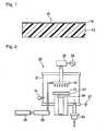
- Fig. 2is schematic structural view of a plasma CVD apparatus used in Examples.
- the plasma CVD apparatus 20is composed of a vacuum chamber 21, an upper shower head electrode 22 and a lower electrode 23 which are provided so as to face each other, a temperature control apparatus 24 which is provided below the lower electrode 23, a high-frequency power source 26 with 13.56 MHz which is connected to the upper shower head electrode 22 via a matching box 25, an earth 27 which contacts to the lower electrode 23, and a gas tank 29 which supplies gas to the upper shower head electrode 22 through a mass flow controller 28, in the vacuum chamber 21; a vacuum pump 30 which is provided at the bottom portion of the vacuum chamber 21 for evacuation; and a pressure gauge 31 which is provided at a side part of the vacuum chamber 21.
- the upper shower head electrode 22 and the lower electrode 23are disk-shape parallel flat plate electrodes each having a diameter of 100 mm, while in Examples 3 and 4 and Comparative Example 4, they are rectangular parallel flat plate electrodes of 100 mm x 170 mm, and plasma is generated by glow electric discharge between the upper shower head electrode 22 and the lower electrode 23.
- the upper shower head electrode 22serves also as a means to supply gas.
- the substrate 12On the surface of the lower electrode 23, facing the upper shower head electrode 22, the substrate 12 can be detachably fixed.
- Fig. 2Only one line of the mass flow controller 28 and the gas tank 29 is shown on Fig. 2 . However, in a case where three types of gas are used, one line of the gas flow controller 28 and the gas tank 29 may be provided for each gas, namely the total of three lines may be provided. The gases from respective lines are mixed at the inlet of the vacuum chamber, and then the mixed gas is supplied to the upper shower head electrode 22.
- the vacuum pump 30is provided for evacuation.
- the A light source visible transmittance of the substrate after film formationwas measured by means of a transmittance measuring apparatus M304 (manufactured by Asahi Spectra Co., Ltd.). Specifically by using a standard light source A defined in JIS Z8720, a visible sensitive efficiency defined in JIS Z8113 was measured. A value measured without putting the substrate was set to be 100, and a measured value in a case where the substrate was put on the optical path was calculated.
- the A light source visible transmittanceis an index which shows brightness when human see an object through the substrate.
- the water contact angle of a silicon oxide filmwas measured by a contact-angle measuring apparatus (model CA-X150, manufactured by Kyowa Interface Science Co., Ltd.) in accordance with JIS R3257.
- a silicon oxide filmwas formed in the same manner as in Example 1 except that the condition for forming a film was changed as shown in Table 1, and respective measurements were carried out. Tables 1 to 3 show results. Further, unit (ccm) of each gas component in the Tables is a converted value of (cc)/min at 25°C at 1 atm.
- a silicon oxide filmwas formed in the same manner as in Example 1, except that as a substrate 12, a PET film (50 mm ⁇ 50 mm ⁇ thickness 50 ⁇ m, water contact angle: 75.6°, the A light source visible transmittance: 85.3%) was used, and the condition for forming a film was changed as shown in Table 2, and respective measurements were carried out. Table 2 shows results. TABLE 1 Ex. 1 Ex. 2 Ex. 3 Ex.
- the transmittance of the ETFE film after film formationwas higher than that of the ETFE film before film formation. Further, the water contact angle of the surface of the silicon oxide film was at most 20°, and the silicon oxide film thereby had hydrophilicity.
- Comparative Example 8the atomic ratio of oxygen atoms to silicon atoms (O/Si) was the out of the range of 1.7 to 25, transmittance of the ETFE film after the film formation was low, and the water contact angle of the surface of the silicon oxide film could not be sufficiently low.
- the ETFE copolymer molded product produced by the production method of the present inventionhas a high hydrophilicity and is excellent light transmission properties, whereby it is useful as an agricultural film, various display members (liquid crystal display, plasma display, CRT, etc.), a protective film for solar batteries, etc.
Landscapes
- Chemical & Material Sciences (AREA)
- Chemical Kinetics & Catalysis (AREA)
- Organic Chemistry (AREA)
- Health & Medical Sciences (AREA)
- Medicinal Chemistry (AREA)
- Polymers & Plastics (AREA)
- Engineering & Computer Science (AREA)
- General Chemical & Material Sciences (AREA)
- Materials Engineering (AREA)
- Mechanical Engineering (AREA)
- Metallurgy (AREA)
- Inorganic Chemistry (AREA)
- Physics & Mathematics (AREA)
- Plasma & Fusion (AREA)
- Laminated Bodies (AREA)
- Chemical Vapour Deposition (AREA)
- Coating Of Shaped Articles Made Of Macromolecular Substances (AREA)
Description
- The present invention relates to an ethylene/tetrafluoroethylene copolymer molded product and a method for its production
- An ethylene/tetrafluoroethylene copolymer (hereinafter referred to as ETFE copolymer) is a polymer having weather resistance and chemical resistance inherent to a fluoropolymer and flexibility inherent to a hydrocarbon polymer. Further, the ETFE copolymer is a material having a low refractive index, whereby reflection of light is little, and light transmittance is high.
- Accordingly, the ETFE copolymer molded product is widely used as a material for e.g. an exterior film for system kitchens, a surface film of a white board for marker pens, a mold release film, an outdoor film, a member for displays or a protective film for solar batteries.
- Since the ETFE copolymer is a fluoropolymer, the surface energy is low. Therefore, the contact angle to water (hereinafter referred to as water contact angle) is at least 100°. Accordingly, water droplets tend to be formed on the surface.
- Therefore, in a case where an ETFE copolymer film is used as an agricultural film for e.g. a greenhouse, the film is likely to be fogged with water droplets condensed on the surface of the ETFE copolymer film, or water droplets may drop.
- Further, in a case where the ETFE copolymer film is used for a member for displays or a protective film for solar batteries, and the film surface is fogged with water droplets, visibility becomes poor, or electric power generation efficiency becomes low.
- As an agricultural film, which is made of a fluoropolymer having a low water contact angle and a high hydrophilic property (high antifogging property) surface, the following film has been proposed.
- An agricultural film having a layer comprising a photocatalyst such as titanium oxide and silicon oxide, formed on the surface of a film made of a fluoropolymer (Patent Document 1).
- However, light transmittance of such a film is low for the following reasons.
- (i) The photocatalyst absorbs light.
- (ii) The layer comprising titanium oxide and silicon oxide has a high refractive index, whereby the light reflection is large.
- It is an object of the present invention to provide an ETFE copolymer molded product of which the surface has a high hydrophilic property and which is excellent in the light transmission property, and a method for producing the molded product.
- The present invention has the following constructions.
- (1) A method for producing an ethylene/tetrafluoroethylene copolymer molded product comprising a substrate made of a material containing at least 50 mass% of an ethylene/tetrafluoroethylene copolymer, and a fluorine-doped silicon oxide film formed on the surface of the substrate, characterized by supplying electric power between electrodes so that the electrical power density between the electrodes becomes from 0.5 to 1.1 W/cm3 to cause discharge and thus to plasmatize the following mixed gas so as to form the silicon oxide film on the substrate.
Mixed gas: comprising silicon tetrafluoride, oxygen and a hydrocarbon, wherein the atomic ratio of oxygen atoms to carbon atoms (O/C) is from 1 to 10, and the atomic ratio of oxygen atoms to silicon atoms (O/Si) is from 1.7 to 25. - (2) The method for producing an ethylene/tetrafluoroethylene copolymer molded product according to the above (1), wherein the temperature of substrate at the time of forming the silicon oxide film is at most 150°C. In the silicon oxide film of the ethylene/tetrafluoroethylene copolymer molded product obtainable according to the method above (1) or (2), the atomic ratio of oxygen atoms to silicon atoms (O/Si) is from 1.6 to 2.5, and the atomic ratio of fluorine atoms to silicon atoms (F/Si) is from 0.05 to 0.50. The water contact angle of the silicon oxide film of the ethylene/tetrafluoroethylene copolymer molded product obtainable according to any one of the method above (1) to (2) is at most 20°.
- (3) An ethylene/tetrafluoroethylene copolymer molded product comprising a substrate made of a material containing at least 50 mass% of an ethylene/tetrafluoroethylene copolymer, and a fluorine-doped silicon oxide film formed on the surface of the substrate,characterized in that in the silicon oxide film, the atomic ratio of oxygen atoms to silicon atoms (O/Si) is from 1.6 to 2.5, and the atomic ratio of fluorine atoms to silicon atoms (F/Si) is from 0.05 to 0.50, the water contact angle of the silicon oxide film is at most 20°, and an A light source luminous transmittance of the ethylene/tetrafluoroethylene copolymer molded product is from 93 to 100%.
- (4) The ethylene/tetrafluoroethylene copolymer molded product according to the above (3), wherein the molar ratio of polymerized units based on tetrafluoroethylene/polymerized units based on ethylene is from 30/70 to 70/30.
- The ETFE copolymer molded product of the present invention has a highly hydrophilic surface and is excellent in the light transmission property.
- According to the method of the present invention for producing an ETFE copolymer molded product, it is possible to produce an ETFE copolymer molded product which has a highly hydrophilic surface and is excellent in the light transmission property.
Fig. 1 is a cross-sectional view showing one example of the ETFE copolymer molded product of the present invention.Fig. 2 is a schematic structural view showing a plasma CVD.apparatus used in Examples.- 10: Molded product (ETFE copolymer molded product)
- 12: Substrate
- 14: Silicon oxide film
Fig. 1 is a cross-sectional view showing one example of the ETFE copolymer molded product (hereinafter referred to as molded product) of the present invention.Molded product 10 comprises asubstrate 12 and asilicon oxide film 14 formed on thesubstrate 12.- The
substrate 12 is a molded product made of a material containing at least 50 mass% of an ETFE copolymer (hereinafter referred to as ETFE material). The shape of thesubstrate 12 may be a film form, sheet form, tube form, pipe form or fiber form, and the film form or the sheet form is preferred. The thickness of the film or sheet is preferably from 10 to 500 µm. - The ETFE copolymer may be a copolymer of tetrafluoroethylene and ethylene (hereinafter referred to as ETFE), a terpolymer of tetrafluoroethylene, ethylene and another monomer, or a multipolymer of tetrafluoroethylene, ethylene and at least two other monomers.
- The molar ratio of polymerized units based on tetrafluoroethylene (hereinafter referred to as TFE)/polymerized units based on ethylene (hereinafter referred to as E) in the ETFE copolymer (TFE/E) is preferably from 30/70 to 70/30, more preferably from 45/55 to 65/35, particularly preferably from 50/50 to 65/35. When TFE/E is within the above range, the solvent resistance, the mold release properties, the heat resistance, the mechanical strength and the molten moldability, etc. improve.
- The ETFE copolymer may contain polymerized units based on other monomers.
- Such other monomers may, for example, be a fluoroolefin such as vinylidene fluoride, hexafluoropropylene, CH2=CH(CF2)4F or CH2=CF(CF2)5F; a perfluoro(alkyl vinyl ether) such as CF2=CFO(CF2)3F; an olefin such as propylene or butene; a vinyl ester such as vinyl acetate or vinyl pivalate; an acrylate such as (polyfluoroalkyl)acrylate; and a methacrylate such as (polyfluoroalkyl)methacrylate. Such other monomers may be used alone or in combination as mixture of two or more of them.
- Such other monomers are more preferably hexafluoropropylene, CH2=CH(CF2)4F and CF2=CFO(CF2)3F, particularly preferably CH2=CH(CF2)4F.
- The content of polymerized units based on other monomers is preferably from 0.01 to 10 mol%, more preferably from 0.1 to 7 mol%, particularly preferably from 0.5 to 5 mol%, based on the total polymerized units in the ETFE copolymer (100 mol%).
- The ETFE material contains at least 50 mass% of the ETFE copolymer, preferably contains at least 70 mass% of the ETFE copolymer, particularly preferably a material wherein all components other than additives are the ETFE copolymer.
- The ETFE material may contain other polymers. Such other polymers may, for example, be other fluoropolymers or non-fluoropolymers.
- Such other fluoropolymers may, for example, be a hexafluoropropylene-tetrafluoroethylene copolymer, a perfluoro(alkyl vinyl ether)-tetrafluoroethylene copolymer, a tetrafluoroethylene-hexafluoropropylene-vinylidene fluoride copolymer and a chlorotrifluoroethylene-ethylene copolymer.
- Such other polymers may be used alone or in combination as a mixture of two or more of them.
- As a case requires, the ETFE material may contain a known additive such as a pigment, an ultraviolet absorber, carbon black, carbon fiber, silicon carbide, glass fiber, mica or a crosslinking agent.
- A
silicon oxide film 14 is a fluorine-doped silicon film. - Silicon, oxygen and fluorine in the
silicon oxide film 14 preferably satisfy the following atomic ratio. - The atomic ratio of oxygen atoms to silicon atoms (O/Si) is from 1.6 to 2.5, and the atomic ratio of fluorine atoms to silicon atoms (F/Si) is from 0.05 to 0.50.
- The
silicon oxide film 14 preferably contains carbon atoms. - The atomic ratio of oxygen to silicon (O/Si) in the
silicon oxide film 14 is from 1.6 to 2.5, particularly preferably from 1.9 to 2.1. Usually, in a case where a silicon oxide film is formed, O/Si becomes 2.0. When O/Si is at least 1.6, formation of dangling-bond of silicon oxide can be prevented, and deterioration of the light transmission property due to the dangling-bond can be prevented. When O/Si is at most 2.5, formation of Si-OH bond can be prevented, and deterioration of the light transmission property due to the Si-OH bond can be prevented. - The atomic ratio of fluorine atoms to silicon atoms (F/Si) in the
silicon oxide film 14 is from 0.05 to 0.50, particularly preferably from 0.06 to 0.1. When F/Si is at least 0.05, transmittance of ultraviolet ray can be suppressed to be low, and it is possible to form a silicon oxide film suitable for a cover glass for solar batteries using ultraviolet ray, an agricultural film etc. When F/Si is at most 0.50, water absorption can be suppressed, and as a result, reaction of thesilicon oxide film 14 with water can be suppressed, and durability of thesilicon oxide film 14 can be improved. - The composition of the
silicon oxide film 14 is a composition of a silicon oxide film surface (namely inside of the silicon oxide film 14) after removing a surface layer of thesilicon oxide film 14 by etching. - The composition of the
silicon oxide film 14 is obtained by measuring the wide spectrum of the surface of an etched silicon oxide film by using an electron spectroscopy for chemical analysis (ESCA), observing the peak intensities of C1s, O1s, F1s and Si2p orbits and calculating the atomic ratios of oxygen, fluorine and silicon. Specifically, by using a sputtering apparatus provided in the inside of an electron spectroscopy for chemical analysis (model 5500, manufactured by ULVAC-PHI, Incorporated), the surface layer of thesilicon oxide film 14 is etched for from 3 to 5 nm as calculated as silica glass by the sputtering with argon, and the composition of the surface (inside of the silicon oxide film 14) of the silicon oxide film after etching is measured by using the electron spectroscopy for chemical analysis. - The water contact angle of the
silicon oxide film 14 is preferably at most 20°, more preferably at most 15°, particularly preferably at most 10° (ultrahydrophilic). - The water contact angle is measured in accordance wit JIS R3257 by using a commercially available contact angle tester.
- The refractive index of the
silicon oxide film 14 at a wavelength of 550 nm is preferably at most 1.42 which is a refractive index of ETFE, particularly preferably from 1.30 to 1.40. When the refractive index is at most 1.42, the effect to prevent reflection at the film surface can be obtained, and the light transmission property can be improved. When the refractive index is at least 1.30, it is possible to suppress deterioration of mechanical durability caused by the density of thesilicon oxide film 14 becoming too low. - The refractive index can be calculated by a method of measuring the transmittance and reflectivity of the
silicon oxide film 14 by using a commercially available spectrophotometer and obtaining an average refractive index by an optical simulation. - The film thickness of the
silicon oxide film 14 is preferably from 40 to 120 nm, particularly preferably from 60 to 100 nm. When the film thickness is at least 40 nm, a sufficient low reflection effect can be obtained. When the film thickness is at most 120 nm, light absorption of thesilicon oxide film 14 can be suppressed, and deterioration of the light transmission property can be suppressed. Further, when the film thickness is at most 120 nm, deterioration of mechanical durability of thesilicon oxide film 14 can be suppressed. - In a case where a
substrate 12 is a film or a sheet, thesilicon oxide film 14 may be formed on one side of thesubstrate 12, or may be formed on both sides of thesubstrate 12. - Molded
product 10 may contain another layer. Such another layer may, for example, be another substrate formed on the side ofsubstrate 12, on which thesilicon oxide film 14 is not formed, an adhesive layer for bonding substrates each other, a coating film which is formed by liquid phase coating by a sol-gel method or the like, or a thin film formed by a sputtering method, a vapor deposition method or the like. - The material of such another substrate may, for example, be a fluoropolymer, a non-fluoropolymer or glass.
- The A light source visible transmittance of the ETFE copolymer molded product is preferably from 93 to 100%, more preferably from 94 to 100%. When the A light source visible transmittance of the ETFE copolymer molded product is at least 94%, the light transmission properties required for an agricultural film, various display members (liquid crystal display, plasma display, CRT etc.), a protective film for solar batteries, etc. can be satisfied. The A light source luminous transmittance is a luminous efficiency which is defined in JIS Z8113 and which is measured by using standard light source A defined in JIS Z8720 and calculated from a measured value in a case where a substrate is put on an optical path, where a value measured without putting a substrate is set to be 100. The A light source luminous transmittance is an index which shows brightness in a case where human see an object through a substrate.
- A molded
product 10 is produced by a method of supplying electric power between electrodes to cause discharge and thus plasmatize a specific mixed gas, whereby a fluorine-dopedsilicon oxide film 14 is formed on thesubstrate 12. - The mixed gas contains silicon tetrafluoride, oxygen and a hydrocarbon.
- The atomic ratio of oxygen atoms to carbon atoms (O/C) in the mixed gas is from 1 to 10, preferably from 2.5 to 5.0. When O/C is at least 1, the amount of oxygen is large, and carbon is not likely to remain on a silicon oxide film, whereby it is possible to suppress increase of a refractive index and deterioration of the light transmission property caused by carbon. When O/C is at most 10, a formed silicon oxide film becomes porous, and as a result a
silicon oxide film 14 having a sufficient low refractive index can be formed. - The atomic ratio of oxygen atoms to silicon atoms (O/Si) in the mixed gas is from 1.7 to 25, preferably from 3 to 10. If O/Si is less than 1.7, its value is much lower than the theoretical ratio of 2.0 at which a SiO2 bond can be formed, a sufficient amount of SiO2 cannot be formed, and there is a problem that the utilization efficiency of materials deteriorates, and the cost for forming a film increases. Further, if O/Si exceeds 25, the reaction to form SiO2 occurs in a gas phase space, fine powders are formed, and continuous operation time of the apparatus tends to be short, such being undesirable.
- If the mixed gas contains a hydrocarbon, it is possible to obtain effects that (i) a formation rate of a film is improved, (ii) the
silicon oxide film 14 can be formed at a low temperature, (iii) thesilicon oxide film 14 having a sufficiently low refractive index can be formed, and (iv) the mechanical durability and the chemical durability of thesilicon oxide film 14 can be improved. - The mechanisms of (i) and (ii) are considered to be as follows.
- In a case where the mixed gas contains no hydrocarbon, the reaction of silicon tetrafluoride and oxygen can be represented by the following formula (1):
SiF4+5O2=SiO2+4O2F (1) - In a case where the mixed gas contains a hydrocarbon (such as methane or ethane), the reaction of silicon tetrafluoride, oxygen and the hydrocarbon are represented by the following formulae (2) to (5):
SiF4+2O2+CH4=SiO2+CO2+4HF (2)
SiF4+2O2+CH4=SiO2+CF4+2H2O (3)
SiF4+3O2+C2H4=SiO2+2CO2+4HF (4)
iF4+1.5O2+C2H4=SiO2+CF4+H2O (5) - Standard free energy changes ΔG in the reactions (1) to (5) are shown below:
- (1): +823 kJ/mol
- (2): -726 kJ/mol
- (3): -596 kJ/mol
- (4): -1239 kJ/mol
- (5): -443 kJ/mol
- The larger ΔG is, the less the reaction proceeds, and when ΔG is a positive value, the reaction is not likely to particularly proceed. ΔG in the reaction (1) is a positive value, and ΔG in the reactions (2) to (5) is a negative value. Therefore, in a case where a hydrocarbon is contained, the decomposition reaction of silicon tetrafluoride tends to proceed, and as a result the speed to form a film is improved, and the
silicon oxide film 14 can be formed at a low temperature. - The reason for (iii) is considered to be as follows.
- In a case where a hydrocarbon is contained in the mixed gas, a stable gas such as carbon dioxide or carbon tetrafluoride is formed as shown in the reactions (2) to (5). While forming a film, the gas taken into the
silicon oxide film 14 leaks from thesilicon oxide film 14, whereby many voids are formed in thesilicon oxide film 14, and as a result, a refractive index of thesilicon oxide film 14 becomes sufficiently low, reflection can be suppressed, and the light transmission property is improved. - The reason for (iv) is considered to be as follows.
- In a case where a hydrocarbon is contained in the mixed gas, a trace amount of crosslinked carbon remains in the
silicon oxide film 14, whereby the mechanical durability is improved. Further, a layer containing a large amount of carbon is formed at an extremely thin region of the surface layer of thesilicon oxide film 14, whereby lubricity of the surface of thesilicon oxide film 14 is improved, and as a result, friction resistance and scratch resistance are improved, while the chemical durability against water is improved. - The hydrocarbon may be a saturated hydrocarbon or an unsaturated hydrocarbon. From the viewpoint of the easiness of decomposition in plasma, the hydrocarbon is preferably a C1-4 hydrocarbon, more preferably a C1-3 hydrocarbon, further preferably a C1-2 hydrocarbon such as methane, ethane or ethylene, and from the viewpoint of satisfying both the light transmission property and the mechanical durability, ethylene is particularly preferred.
- The mixed gas may contain a gas having an effect to stabilize electric discharge such as nitrogen or argon. Such gas is preferably nitrogen, from the viewpoint of satisfying both the light transmission property and the mechanical durability.
- The mixed gas preferably contains only silicon tetrafluoride as a gas containing silicon. Silicon tetrafluoride has characteristics: (I) since it is gas at room temperature, handling is simple, (II) since it is a relatively stable compound in plasma, fine powder is seldom formed in a chamber, and it is possible to form a film only on a substrate surface, whereby the chamber is not likely to be stained, as compared to a gas containing another silicon such as silane or alkoxysilane, and (III) since fine powder is not formed in the chamber, formation of a weak bond in the
silicon oxide film 14 due to deposition of the fine powder can be prevented, whereby thesilicon oxide film 14 having a sufficient mechanical durability can be formed. - The mixed gas is plasmatized by using a conventional plasma CVD apparatus.
- For example, the mixed gas is plasmatized by introducing the mixed gas in a chamber of the plasma CVD apparatus and supplying electric power from a high frequency electric source between two electrodes provided in the chamber to cause electric discharge between the two electrodes.
- The type of discharge may, for example, be glow discharge, corona discharge, arc discharge or non-audible discharge, and the glow electric discharge is preferred, since uniform plasma having a large area can be easily formed. The electric discharge may be continuous electric discharge which can be carried out continuously or pulse electric discharge which is carried out intermittently.
- The pressure in the chamber is preferably a pressure at which glow electric discharge is generated, and it is particularly preferably from 1 to 200 Pa, since the glow electric discharge is stable.
- The electric power density is from 0.5 to 1.1 W/cm3, preferably from 0.8 to 1.0 W/cm3. When the electric power density is within the above range, it is possible to form a
silicon oxide film 14 having a water contact angle of at most 20°. Further, when the electric power density is sufficiently high, silicon tetrafluoride is sufficiently decomposed, and asilicon oxide film 14 having a sufficient film thickness can be formed. Further, in such a case, it is possible to prevent carbon from remaining in thesilicon oxide film 14, and deterioration of the light transmission property of thesilicon oxide film 14 can be suppressed. The electric power density is a value obtained by dividing the electric power by a volume between the electrodes. - The temperature of the
substrate 12 is preferably at most 150°C. When the temperature of thesubstrate 12 is at most 150°C, deterioration of the mechanical durability can be suppressed. Further, deterioration of the light transmission property due to the deterioration of thesubstrate 12 can be suppressed. - The lower limit of the temperature of the
substrate 12 is not particularly restricted, so long as the flexibility of thesubstrate 12 is not impaired, and it is preferably at least -20°C. When the temperature of thesubstrate 12 is at least -20°C, a sufficient formation rate of the film can be secured. Further, the production cost can be reduced. - The temperature of the
substrate 12 can be cooled by circulating air, and it is particularly preferably from 30 to 80°C, from the viewpoint of reducing the production cost. - In the above-described method for producing the molded
product 10, a mixed gas is used which contains silicon tetrafluoride, oxygen and a hydrocarbon, wherein the atomic ratio of oxygen atoms to carbon atoms (O/C) is from 1 to 10, and the atomic ratio of oxygen atoms to silicon atoms (O/Si) is from 1.7 to 25, and under the condition of the electric power density of from 0.5 to 1.1 W/cm3, the mixed gas is plasmatized to form asilicon oxide film 14 on asubstrate 12, whereby it is possible to produce a moldedproduct 10, of which the surface has high hydrophilicity and which is excellent in the light transmission property. - The reason why the hydrophilicity of the
silicon oxide film 14 becomes high is considered to be as follows. - When the mixed gas is plasmatized under the condition of the electric power density of from 0.5 to 1.1 W/cm3, fluorine radicals are formed from the ETFE copolymer contained in the
substrate 12 and contacted with plasma, and the fluorine radicals attach on a surface of thesilicon oxide film 14. Since the fluorine radicals are relatively stable, they can be present on the substrate surface after the plasma treatment, and a large amount of hydroxyl groups is formed on the surface of thesilicon oxide film 14 by the reaction of oxygen and moisture in air. Having the hydroxyl groups, the surface of thesilicon oxide film 14 shows a hydrophilicity with a water contact angle of at most 20°. - On the other hand, in a case where the substrate is a non-fluoropolymer such as a polyethylene terephthalate (hereinafter referred to as PET), fluorine radicals are not formed from the substrate, the number of fluorine radicals which attach on the surface of the
silicon oxide film 14 is small, and a hydrophilic surface cannot be formed. - The reason why the molded
product 10 is excellent in the light transmission property is as follows. - As compared to a normal silicon oxide film, the fluorine-doped
silicon oxide film 14 has a low refractive index. Further, many voids are formed in thesilicon oxide film 14 formed by the method of the present invention, whereby an apparent refractive index of thesilicon oxide film 14 is further lowered. When the apparent refractive index of thesilicon oxide film 14 is lower than that of the substrate 12 (in the case of ETFE, 1.42), light reflection can be suppressed. Further, in such a case, thesilicon oxide film 14 little absorbs light in the visible light region, whereby the reduction of the transmittance due to light absorption is also little. - Now, the present invention will be described in detail with reference to Examples, but it should be understood that the present invention is not limited thereto.
Fig. 2 is schematic structural view of a plasma CVD apparatus used in Examples. Theplasma CVD apparatus 20 is composed of avacuum chamber 21, an uppershower head electrode 22 and a lower electrode 23 which are provided so as to face each other, atemperature control apparatus 24 which is provided below the lower electrode 23, a high-frequency power source 26 with 13.56 MHz which is connected to the uppershower head electrode 22 via amatching box 25, anearth 27 which contacts to the lower electrode 23, and agas tank 29 which supplies gas to the uppershower head electrode 22 through amass flow controller 28, in thevacuum chamber 21; avacuum pump 30 which is provided at the bottom portion of thevacuum chamber 21 for evacuation; and apressure gauge 31 which is provided at a side part of thevacuum chamber 21.- In Examples 1, 2, 5 and 6 and Comparative Examples 1 to 3, 5 and 6 to 8, the upper
shower head electrode 22 and the lower electrode 23 are disk-shape parallel flat plate electrodes each having a diameter of 100 mm, while in Examples 3 and 4 and Comparative Example 4, they are rectangular parallel flat plate electrodes of 100 mm x 170 mm, and plasma is generated by glow electric discharge between the uppershower head electrode 22 and the lower electrode 23. - The upper
shower head electrode 22 serves also as a means to supply gas. - On the surface of the lower electrode 23, facing the upper
shower head electrode 22, thesubstrate 12 can be detachably fixed. - Only one line of the
mass flow controller 28 and thegas tank 29 is shown onFig. 2 . However, in a case where three types of gas are used, one line of thegas flow controller 28 and thegas tank 29 may be provided for each gas, namely the total of three lines may be provided. The gases from respective lines are mixed at the inlet of the vacuum chamber, and then the mixed gas is supplied to the uppershower head electrode 22. - The
vacuum pump 30 is provided for evacuation. - The A light source visible transmittance of the substrate after film formation was measured by means of a transmittance measuring apparatus M304 (manufactured by Asahi Spectra Co., Ltd.). Specifically by using a standard light source A defined in JIS Z8720, a visible sensitive efficiency defined in JIS Z8113 was measured. A value measured without putting the substrate was set to be 100, and a measured value in a case where the substrate was put on the optical path was calculated. The A light source visible transmittance is an index which shows brightness when human see an object through the substrate.
- The water contact angle of a silicon oxide film was measured by a contact-angle measuring apparatus (model CA-X150, manufactured by Kyowa Interface Science Co., Ltd.) in accordance with JIS R3257.
- By using a sputtering apparatus provided in a photoelectron spectrometry (model 5500, manufactured by ULVAC PHI,), from 3 to 5 nm as calculated as silica glass of the top layer of a silicon oxide film was etched by sputtering with argon, the wide spectrum of the surface of the silicon oxide film (inside of the silicon oxide film) after etching was measured by using the photoelectron spectrometry, and the molar ratios of oxygen atoms, fluorine atoms and silicon atoms were calculated by measuring the peak intensities of C1s, O1s, F1s and Si2p orbits.
- An ETFE film (product name AFLEX, manufactured by Asahi Glass Company, Limited, TFE/E=50/50, length 50 mm × width 50 mm × thickness 50 µm, water contact angle: 108°, the A light source visible transmittance: 92%) was put on the lower electrode 23, and the distance between the upper
shower head electrode 22 and the lower electrode 23 was fixed to be 3 cm. Then, thevacuum chamber 21 was sealed, by using thevacuum pump 30 for evacuation, evacuation was carried out until the pressure in thevacuum chamber 21 became at most 0.1 Pa, and gas in thevacuum chamber 21 was evacuated. Then, while operating the vacuum pump, ethylene, oxygen and silicon tetrafluoride were introduced in thevacuum chamber 21 fromrespective gas tanks 29 throughmass flow controller 28 at a flow rate shown in Table 1. The pressure in thevacuum chamber 21 was 42 Pa. Table 1 shows O/C and O/Si in the mixed gas in thevacuum chamber 21. - Then, from the high
frequency power source 25, electric power of 240 W was supplied between the uppershower head electrode 22 and the lower electrode 23 to generate glow electric discharge (continuous electric discharge), the glow electric discharge was maintained for 2 minutes to form a silicon oxide film on one surface of the ETFE film. During the glow electric discharge, the temperature of the ETFE film was 51°C. The electric power supply from the highfrequency power source 26 was stopped, air was introduced in thevacuum chamber 21 so as to be atmospheric pressure, and the ETFE film (ETFE copolymer molded product) was removed. - Some measurements were carried out on the ETFE film after the film formation. Table 1 shows results. EXAMPLES 2 to 6, COMPARATIVE EXAMPLES 1 to 4 and 6 to 8
- A silicon oxide film was formed in the same manner as in Example 1 except that the condition for forming a film was changed as shown in Table 1, and respective measurements were carried out. Tables 1 to 3 show results. Further, unit (ccm) of each gas component in the Tables is a converted value of (cc)/min at 25°C at 1 atm.
- A silicon oxide film was formed in the same manner as in Example 1, except that as a
substrate 12, a PET film (50 mm × 50 mm × thickness 50 µm, water contact angle: 75.6°, the A light source visible transmittance: 85.3%) was used, and the condition for forming a film was changed as shown in Table 2, and respective measurements were carried out. Table 2 shows results.TABLE 1 Ex. 1 Ex. 2 Ex. 3 Ex. 4 Substrate ETFE ETFE ETFE ETFE Condition for forming a film Hydrocarbon (ccm) C2H4 19 C2H4 6 C2H4 9 C2H4 9 O2 (ccm) 50 50 30 30 SiF4 (ccm) 11 5 11 11 N2 (ccm) 6 6 0 0 Mixed gas (atomic ratio) O/C 2.6 7.8 3.3 3.3 O/Si 9.5 19.0 5.7 5.7 Pressure (Pa) 42 40 48 48 Substrate temperature (°C) 51 45 29 26 Distance between electrodes (cm) 3 3 3 5 Electric power (W) 240 200 400 450 Electric density (W/cm3) 1.0 0.8 0.8 0.5 Treatment time (min) 2 2 3 3 Film formation result A light source visible transmittance (%) 94 93.1 94 93.9 Water contact angle (°) 5 15 5.6 16.2 Inside film (atomic ratio) F/Si 0.14 0.22 0.10 0.09 O/Si 2.10 1.9 1.97 2.05 TABLE 2 Comp Ex. 1 Comp. Ex. 2 Comp. Ex. 3 Comp. Ex. 4 Comp. Ex. 5 Substrate ETFE ETFE ETFE ETFE PET Condition for forming a film Hydrocarbon (ccm) CH4 15 C2H4 13 C2H4 6 C2H4 9 C2H4 12 O2 (ccm) 8 16 26 30 50 SiF4 (ccm) 0 0 9 11 21 N2 (ccm) 0 0 3 0 0 Mixed gas (atomic ratio) O/C 1.1 1.3 4.1 3.3 2.6 O/Si - - 5.7 5.7 9.5 Pressure (Pa) 30 22 47 48 41 Substrate temperature (°C) 50 42 46 18 48 Distance between electrodes (cm) 2 3 1 4 3 Electric power (W) 125 175 200 300 230 Electric density (W/cm3) 0.8 0.7 1.2 0.4 0.8 Treatment time (min) 2 2 3 3 4 Film formation result A light source visible transmittance (%) 90.9 87.9 93 92.6 89.7 Water contact angle (°) 5.3 3.9 33.5 62.7 60.8 Inside film (atomic ratio) F/Si - - 0.03 1.1 0.102 O/Si - - 1.98 3.1 2.01 TABLE 3 Ex. 5 Ex. 6 Comp. Ex. 6 Comp. Ex. 7 Comp. Ex. 8 Substrate Condition for forming a film ETFE ETFE ETFE ETFE ETFE Hydrocarbon (ccm) C2H4 C2H4 C2H4 C2H4 C2H4 19 19 7 9 8 O2 (ccm) 50 50 6 150 70 SiF4 (ccm) 11 11 5 18 14 N2 (ccm) 0 6 0 0 0 Mixed gas (atomic ratio) O/C 2.6 2.6 0.9 16.7 8.3 O/Si 9.5 9.5 2.4 17.1 28.6 Pressure (Pa) 42 42 20 70 48 Substrate temperature (°C) 150 48 40 50.9 37.5 Distance between electrodes (cm) 3 3 3 3 3 Electric power (W) 240 200 200 240 240 Electric density (W/cm3) 1 0.8 0.83 1 1 Treatment time (min) 2 2 1 1 2 Film formation result A light source visible transmittance (%) 93 93.7 89 92.2 91.8 Water contact angle (°) 11.9 6 49.5 35.9 28.4 Inside film (atomic. ratio) F/si 0.11 0.31 - - - O/Si 2 1.81 - - - - In Examples 1 to 6, the transmittance of the ETFE film after film formation was higher than that of the ETFE film before film formation. Further, the water contact angle of the surface of the silicon oxide film was at most 20°, and the silicon oxide film thereby had hydrophilicity.
- In Comparative Examples 1 and 2, since the mixed gas containing no silicon tetrafluoride was used, the transmittance of the ETFE film after the film formation was lower than that of the ETFE film before the film formation.
- In Comparative Examples 3 and 4, the electric density was out of the range of from 0.5 to 1.1 W/cm3, the water contact angle of the surface of the silicon oxide film on the ETFE film after the film formation could not become sufficiently low.
- In Comparative Example 5, since a substrate of a PET film after the film formation was a PET film, the water contact angle of the surface of the silicon oxide film could not become sufficiently low.
- In Comparative Example 6, since the atomic ratio of oxygen atoms to carbon atoms (O/C) was out of the range of from 1 to 10, the transmittance of the ETFE film after the film formation was low, and the water contact angle of the surface of the silicon oxide film could not be sufficiently low.
- In Comparative Example 7, since the atomic ratio of oxygen atoms to carbon atoms (O/C) was out of the range of 1 to 10, the water contact angle of the silicon oxide film on the ETFE film after the film formation could not be sufficiently low.
- In Comparative Example 8, the atomic ratio of oxygen atoms to silicon atoms (O/Si) was the out of the range of 1.7 to 25, transmittance of the ETFE film after the film formation was low, and the water contact angle of the surface of the silicon oxide film could not be sufficiently low.
- The ETFE copolymer molded product produced by the production method of the present invention has a high hydrophilicity and is excellent light transmission properties, whereby it is useful as an agricultural film, various display members (liquid crystal display, plasma display, CRT, etc.), a protective film for solar batteries, etc.
Claims (4)
- A method for producing an ethylene/tetrafluoroethylene copolymer molded product comprising a substrate made of a material containing at least 50 mass% of an ethylene/tetrafluoroethylene copolymer, and a fluorine-doped silicon oxide film formed on the surface of the substrate,characterized by supplying electric power between electrodes so that the electrical power density between the electrodes becomes from 0.5 to 1.1 W/cm3 to cause discharge and thus to plasmatize the following mixed gas so as to form the silicon oxide film on the substrate:Mixed gas comprising silicon tetrafluoride, oxygen and a hydrocarbon, wherein the atomic ratio of oxygen atoms to carbon atoms (O/C) is from 1 to 10, and the atomic ratio of oxygen atoms to silicon atoms (O/Si) is from 1.7 to 25.
- The method for producing an ethylene/tetrafluoroethylene copolymer molded product according to Claim 1, wherein the temperature of substrate at the time of forming the silicon oxide film is at most 150°C.
- An ethylene/tetrafluoroethylene copolymer molded product comprising a substrate made of a material containing at least 50 mass% of an ethylene/tetrafluoroethylene copolymer, and a fluorine-doped silicon oxide film formed on the surface of the substrate,characterized in that in the silicon oxide film, the atomic ratio of oxygen atoms to silicon atoms (O/Si) is from 1.6 to 2.5, and the atomic ratio of fluorine atoms to silicon atoms (F/Si) is from 0.05 to 0.50, the contact angle of the silicon oxide film to water is at most 20°, and an A light source visible transmittance of the ethylene/tetrafluoroethylene copolymer molded product is from 93 to 100%.
- The ethylene/tetrafluoroethylene copolymer molded product according to Claim 3, wherein the molar ratio of polymerized units based on tetrafluoroethylene/polymerized units based on ethylene is from 30/70 to 70/30.
Applications Claiming Priority (2)
| Application Number | Priority Date | Filing Date | Title |
|---|---|---|---|
| JP2006298824 | 2006-11-02 | ||
| PCT/JP2007/066809WO2008053632A1 (en) | 2006-11-02 | 2007-08-29 | Ethylene-tetrafluoroethylene copolymer molded product and method for producing the same |
Publications (3)
| Publication Number | Publication Date |
|---|---|
| EP2096191A1 EP2096191A1 (en) | 2009-09-02 |
| EP2096191A4 EP2096191A4 (en) | 2011-08-17 |
| EP2096191B1true EP2096191B1 (en) | 2015-04-01 |
Family
ID=39343983
Family Applications (1)
| Application Number | Title | Priority Date | Filing Date |
|---|---|---|---|
| EP07806286.6ANot-in-forceEP2096191B1 (en) | 2006-11-02 | 2007-08-29 | Ethylene-tetrafluoroethylene copolymer molded product and method for producing the same |
Country Status (6)
| Country | Link |
|---|---|
| US (1) | US8043668B2 (en) |
| EP (1) | EP2096191B1 (en) |
| JP (1) | JP5093113B2 (en) |
| CN (1) | CN101528976B (en) |
| CA (1) | CA2668153A1 (en) |
| WO (1) | WO2008053632A1 (en) |
Families Citing this family (25)
| Publication number | Priority date | Publication date | Assignee | Title |
|---|---|---|---|---|
| CN102177204B (en)* | 2008-10-09 | 2013-09-18 | 旭硝子株式会社 | Dark-colored fluororesin films and backsheets for solar cell modules |
| EP2251454B1 (en) | 2009-05-13 | 2014-07-23 | SiO2 Medical Products, Inc. | Vessel coating and inspection |
| WO2011004682A1 (en)* | 2009-07-09 | 2011-01-13 | コニカミノルタホールディングス株式会社 | Barrier film, organic photoelectric conversion element, and method for manufacturing barrier film |
| US11624115B2 (en) | 2010-05-12 | 2023-04-11 | Sio2 Medical Products, Inc. | Syringe with PECVD lubrication |
| US9878101B2 (en) | 2010-11-12 | 2018-01-30 | Sio2 Medical Products, Inc. | Cyclic olefin polymer vessels and vessel coating methods |
| CA2855353C (en) | 2011-11-11 | 2021-01-19 | Sio2 Medical Products, Inc. | Passivation, ph protective or lubricity coating for pharmaceutical package, coating process and apparatus |
| US11116695B2 (en) | 2011-11-11 | 2021-09-14 | Sio2 Medical Products, Inc. | Blood sample collection tube |
| WO2013152031A1 (en)* | 2012-04-04 | 2013-10-10 | Kla-Tencor Corporation | Protective fluorine-doped silicon oxide film for optical components |
| JP6171275B2 (en)* | 2012-07-02 | 2017-08-02 | 大日本印刷株式会社 | Transparent film and method for producing the same |
| US20150297800A1 (en) | 2012-07-03 | 2015-10-22 | Sio2 Medical Products, Inc. | SiOx BARRIER FOR PHARMACEUTICAL PACKAGE AND COATING PROCESS |
| US9664626B2 (en) | 2012-11-01 | 2017-05-30 | Sio2 Medical Products, Inc. | Coating inspection method |
| US9903782B2 (en) | 2012-11-16 | 2018-02-27 | Sio2 Medical Products, Inc. | Method and apparatus for detecting rapid barrier coating integrity characteristics |
| US9764093B2 (en) | 2012-11-30 | 2017-09-19 | Sio2 Medical Products, Inc. | Controlling the uniformity of PECVD deposition |
| AU2013352436B2 (en) | 2012-11-30 | 2018-10-25 | Sio2 Medical Products, Inc. | Controlling the uniformity of PECVD deposition on medical syringes, cartridges, and the like |
| US20160015898A1 (en) | 2013-03-01 | 2016-01-21 | Sio2 Medical Products, Inc. | Plasma or cvd pre-treatment for lubricated pharmaceutical package, coating process and apparatus |
| US9937099B2 (en) | 2013-03-11 | 2018-04-10 | Sio2 Medical Products, Inc. | Trilayer coated pharmaceutical packaging with low oxygen transmission rate |
| JP6453841B2 (en) | 2013-03-11 | 2019-01-16 | エスアイオーツー・メディカル・プロダクツ・インコーポレイテッド | Coated packaging |
| US20160017490A1 (en) | 2013-03-15 | 2016-01-21 | Sio2 Medical Products, Inc. | Coating method |
| CN104138764B (en)* | 2013-05-10 | 2016-09-28 | 辽宁石油化工大学 | A kind of efficient visible light excites carbon and the preparation method of fluorin-doped titanium dioxide optical catalyst |
| EP3122917B1 (en) | 2014-03-28 | 2020-05-06 | SiO2 Medical Products, Inc. | Antistatic coatings for plastic vessels |
| KR102786617B1 (en) | 2015-08-18 | 2025-03-26 | 에스아이오2 메디컬 프로덕츠, 엘엘씨 | Packaging containers for pharmaceuticals and other products with low oxygen permeability |
| JP6428864B2 (en)* | 2017-07-03 | 2018-11-28 | 大日本印刷株式会社 | Transparent film and method for producing the same |
| WO2020104699A1 (en)* | 2018-11-23 | 2020-05-28 | Fraunhofer-Gesellschaft zur Förderung der angewandten Forschung eingetragener Verein | Coated etfe film, method for producing same, and use of same |
| US11050012B2 (en) | 2019-04-01 | 2021-06-29 | Taiwan Semiconductor Manufacturing Co., Ltd. | Method to protect electrodes from oxidation in a MEMS device |
| EP4091437A1 (en) | 2021-05-20 | 2022-11-23 | Hueck Folien Gesellschaft m.b.H. | Method for producing a hydrophilic coating on a fluoropolymer material |
Family Cites Families (20)
| Publication number | Priority date | Publication date | Assignee | Title |
|---|---|---|---|---|
| JPS5137187B2 (en)* | 1972-12-25 | 1976-10-14 | ||
| US4123602A (en)* | 1976-05-24 | 1978-10-31 | Asahi Glass Company, Ltd. | Terpolymers of tetrafluoroethylene, ethylene and perfluoroalkyl vinyl monomer and process for producing the same |
| JPS59197411A (en)* | 1983-04-25 | 1984-11-09 | Daikin Ind Ltd | Ethylene-tetrafluoroethylene or chlorotrifluoroethylene copolymer |
| US5224441A (en)* | 1991-09-27 | 1993-07-06 | The Boc Group, Inc. | Apparatus for rapid plasma treatments and method |
| JP2939422B2 (en)* | 1994-07-19 | 1999-08-25 | 三井・デュポンフロロケミカル株式会社 | Fluorine-containing resin hydrophilic structure and method for producing the same |
| JP2917897B2 (en)* | 1996-03-29 | 1999-07-12 | 日本電気株式会社 | Method for manufacturing semiconductor device |
| US5661093A (en)* | 1996-09-12 | 1997-08-26 | Applied Materials, Inc. | Method for the stabilization of halogen-doped films through the use of multiple sealing layers |
| JP3829885B2 (en)* | 1997-06-18 | 2006-10-04 | 旭硝子株式会社 | Organic onium compound-containing resin composition |
| JPH1158629A (en) | 1997-08-08 | 1999-03-02 | Daikin Ind Ltd | Agricultural anti-fog film |
| JP4512883B2 (en)* | 1998-12-11 | 2010-07-28 | 株式会社潤工社 | Photocatalyst carrier |
| US6821571B2 (en)* | 1999-06-18 | 2004-11-23 | Applied Materials Inc. | Plasma treatment to enhance adhesion and to minimize oxidation of carbon-containing layers |
| JP4117993B2 (en)* | 2000-01-28 | 2008-07-16 | 旭硝子株式会社 | Laminated body and manufacturing method thereof |
| JP4108999B2 (en)* | 2002-03-26 | 2008-06-25 | 大日本印刷株式会社 | Laminated film |
| KR100470973B1 (en)* | 2003-02-26 | 2005-03-10 | 삼성전자주식회사 | High density plasma chemical vapor deposition process |
| JP2005256061A (en)* | 2004-03-10 | 2005-09-22 | Dainippon Printing Co Ltd | Laminated body |
| US7037855B2 (en)* | 2004-08-31 | 2006-05-02 | Asm Japan K.K. | Method of forming fluorine-doped low-dielectric-constant insulating film |
| JP4581650B2 (en)* | 2004-11-26 | 2010-11-17 | 旭硝子株式会社 | Method for producing synthetic resin molding |
| KR20070091132A (en)* | 2004-12-03 | 2007-09-07 | 아사히 가라스 가부시키가이샤 | Ethylene-Tetrafluoroethylene Copolymer Molded Product and Manufacturing Method Thereof |
| JP2006298824A (en) | 2005-04-21 | 2006-11-02 | Kao Corp | Inhibitor for skatole production in oral cavity |
| US7390757B2 (en)* | 2005-11-15 | 2008-06-24 | Applied Materials, Inc. | Methods for improving low k FSG film gap-fill characteristics |
- 2007
- 2007-08-29CACA002668153Apatent/CA2668153A1/ennot_activeAbandoned
- 2007-08-29WOPCT/JP2007/066809patent/WO2008053632A1/enactiveApplication Filing
- 2007-08-29CNCN2007800402332Apatent/CN101528976B/ennot_activeExpired - Fee Related
- 2007-08-29JPJP2008542010Apatent/JP5093113B2/enactiveActive
- 2007-08-29EPEP07806286.6Apatent/EP2096191B1/ennot_activeNot-in-force
- 2009
- 2009-04-29USUS12/431,906patent/US8043668B2/ennot_activeExpired - Fee Related
Also Published As
| Publication number | Publication date |
|---|---|
| US20090214801A1 (en) | 2009-08-27 |
| CA2668153A1 (en) | 2008-05-08 |
| CN101528976B (en) | 2011-04-20 |
| WO2008053632A1 (en) | 2008-05-08 |
| EP2096191A1 (en) | 2009-09-02 |
| CN101528976A (en) | 2009-09-09 |
| EP2096191A4 (en) | 2011-08-17 |
| JPWO2008053632A1 (en) | 2010-02-25 |
| JP5093113B2 (en) | 2012-12-05 |
| US8043668B2 (en) | 2011-10-25 |
Similar Documents
| Publication | Publication Date | Title |
|---|---|---|
| EP2096191B1 (en) | Ethylene-tetrafluoroethylene copolymer molded product and method for producing the same | |
| JP5880442B2 (en) | GAS BARRIER FILM, METHOD FOR PRODUCING GAS BARRIER FILM, AND ELECTRONIC DEVICE | |
| JP5803937B2 (en) | GAS BARRIER FILM, METHOD FOR PRODUCING GAS BARRIER FILM, AND ELECTRONIC DEVICE | |
| JP6505693B2 (en) | Method of making nanostructures and nanostructured articles | |
| KR101430892B1 (en) | Gas-barrier film and electronic device | |
| JP6329482B2 (en) | Method for depositing a layer on a glass substrate by low pressure PECVD | |
| EP2604427A1 (en) | Laminate, and laminate production method | |
| JP5861644B2 (en) | Method for producing gas barrier film and gas barrier film | |
| US20070228617A1 (en) | Ethylene/tetrafluoroethylene copolymer molding and method for its production | |
| CN111116962B (en) | A kind of preparation method of anti-atomic oxygen film for space polymer material | |
| JP2005256061A (en) | Laminated body | |
| CA2586258A1 (en) | Fluorocarbon film and process for its production | |
| CN102791476A (en) | Laminate and process for production thereof | |
| US20140050864A1 (en) | Method for producing laminate | |
| JP4807195B2 (en) | Method for forming low refractive index film and article having low refractive index film | |
| JP4581650B2 (en) | Method for producing synthetic resin molding | |
| Schmittgens et al. | Large area deposition of functional plasma polymers on polymer substrates | |
| JP2011044453A (en) | Back sheet for solar cell, and solar cell module | |
| US20160083545A1 (en) | Resin product and method of producing the same |
Legal Events
| Date | Code | Title | Description |
|---|---|---|---|
| PUAI | Public reference made under article 153(3) epc to a published international application that has entered the european phase | Free format text:ORIGINAL CODE: 0009012 | |
| 17P | Request for examination filed | Effective date:20090507 | |
| AK | Designated contracting states | Kind code of ref document:A1 Designated state(s):AT BE BG CH CY CZ DE DK EE ES FI FR GB GR HU IE IS IT LI LT LU LV MC MT NL PL PT RO SE SI SK TR | |
| DAX | Request for extension of the european patent (deleted) | ||
| A4 | Supplementary search report drawn up and despatched | Effective date:20110718 | |
| RIC1 | Information provided on ipc code assigned before grant | Ipc:B32B 9/00 20060101ALI20110712BHEP Ipc:C23C 16/509 20060101ALI20110712BHEP Ipc:C23C 16/42 20060101AFI20110712BHEP | |
| RAP1 | Party data changed (applicant data changed or rights of an application transferred) | Owner name:ASAHI GLASS COMPANY, LIMITED | |
| REG | Reference to a national code | Ref country code:DE Ref legal event code:R079 Ref document number:602007040891 Country of ref document:DE Free format text:PREVIOUS MAIN CLASS: C23C0016420000 Ipc:C08J0007060000 | |
| GRAP | Despatch of communication of intention to grant a patent | Free format text:ORIGINAL CODE: EPIDOSNIGR1 | |
| RIC1 | Information provided on ipc code assigned before grant | Ipc:C23C 16/509 20060101ALI20140912BHEP Ipc:C08J 7/06 20060101AFI20140912BHEP Ipc:C23C 16/40 20060101ALI20140912BHEP | |
| INTG | Intention to grant announced | Effective date:20141013 | |
| GRAS | Grant fee paid | Free format text:ORIGINAL CODE: EPIDOSNIGR3 | |
| GRAA | (expected) grant | Free format text:ORIGINAL CODE: 0009210 | |
| AK | Designated contracting states | Kind code of ref document:B1 Designated state(s):AT BE BG CH CY CZ DE DK EE ES FI FR GB GR HU IE IS IT LI LT LU LV MC MT NL PL PT RO SE SI SK TR | |
| REG | Reference to a national code | Ref country code:GB Ref legal event code:FG4D | |
| REG | Reference to a national code | Ref country code:CH Ref legal event code:EP | |
| REG | Reference to a national code | Ref country code:IE Ref legal event code:FG4D | |
| REG | Reference to a national code | Ref country code:DE Ref legal event code:R096 Ref document number:602007040891 Country of ref document:DE Effective date:20150513 | |
| REG | Reference to a national code | Ref country code:AT Ref legal event code:REF Ref document number:719064 Country of ref document:AT Kind code of ref document:T Effective date:20150515 | |
| REG | Reference to a national code | Ref country code:NL Ref legal event code:VDEP Effective date:20150401 | |
| REG | Reference to a national code | Ref country code:AT Ref legal event code:MK05 Ref document number:719064 Country of ref document:AT Kind code of ref document:T Effective date:20150401 | |
| REG | Reference to a national code | Ref country code:LT Ref legal event code:MG4D | |
| PG25 | Lapsed in a contracting state [announced via postgrant information from national office to epo] | Ref country code:NL Free format text:LAPSE BECAUSE OF FAILURE TO SUBMIT A TRANSLATION OF THE DESCRIPTION OR TO PAY THE FEE WITHIN THE PRESCRIBED TIME-LIMIT Effective date:20150401 | |
| PG25 | Lapsed in a contracting state [announced via postgrant information from national office to epo] | Ref country code:LT Free format text:LAPSE BECAUSE OF FAILURE TO SUBMIT A TRANSLATION OF THE DESCRIPTION OR TO PAY THE FEE WITHIN THE PRESCRIBED TIME-LIMIT Effective date:20150401 Ref country code:CZ Free format text:LAPSE BECAUSE OF FAILURE TO SUBMIT A TRANSLATION OF THE DESCRIPTION OR TO PAY THE FEE WITHIN THE PRESCRIBED TIME-LIMIT Effective date:20150401 Ref country code:PT Free format text:LAPSE BECAUSE OF FAILURE TO SUBMIT A TRANSLATION OF THE DESCRIPTION OR TO PAY THE FEE WITHIN THE PRESCRIBED TIME-LIMIT Effective date:20150803 Ref country code:ES Free format text:LAPSE BECAUSE OF FAILURE TO SUBMIT A TRANSLATION OF THE DESCRIPTION OR TO PAY THE FEE WITHIN THE PRESCRIBED TIME-LIMIT Effective date:20150401 Ref country code:FI Free format text:LAPSE BECAUSE OF FAILURE TO SUBMIT A TRANSLATION OF THE DESCRIPTION OR TO PAY THE FEE WITHIN THE PRESCRIBED TIME-LIMIT Effective date:20150401 | |
| PG25 | Lapsed in a contracting state [announced via postgrant information from national office to epo] | Ref country code:GR Free format text:LAPSE BECAUSE OF FAILURE TO SUBMIT A TRANSLATION OF THE DESCRIPTION OR TO PAY THE FEE WITHIN THE PRESCRIBED TIME-LIMIT Effective date:20150702 Ref country code:AT Free format text:LAPSE BECAUSE OF FAILURE TO SUBMIT A TRANSLATION OF THE DESCRIPTION OR TO PAY THE FEE WITHIN THE PRESCRIBED TIME-LIMIT Effective date:20150401 Ref country code:IS Free format text:LAPSE BECAUSE OF FAILURE TO SUBMIT A TRANSLATION OF THE DESCRIPTION OR TO PAY THE FEE WITHIN THE PRESCRIBED TIME-LIMIT Effective date:20150801 Ref country code:LV Free format text:LAPSE BECAUSE OF FAILURE TO SUBMIT A TRANSLATION OF THE DESCRIPTION OR TO PAY THE FEE WITHIN THE PRESCRIBED TIME-LIMIT Effective date:20150401 | |
| REG | Reference to a national code | Ref country code:DE Ref legal event code:R097 Ref document number:602007040891 Country of ref document:DE | |
| PG25 | Lapsed in a contracting state [announced via postgrant information from national office to epo] | Ref country code:EE Free format text:LAPSE BECAUSE OF FAILURE TO SUBMIT A TRANSLATION OF THE DESCRIPTION OR TO PAY THE FEE WITHIN THE PRESCRIBED TIME-LIMIT Effective date:20150401 Ref country code:DK Free format text:LAPSE BECAUSE OF FAILURE TO SUBMIT A TRANSLATION OF THE DESCRIPTION OR TO PAY THE FEE WITHIN THE PRESCRIBED TIME-LIMIT Effective date:20150401 | |
| PLBE | No opposition filed within time limit | Free format text:ORIGINAL CODE: 0009261 | |
| STAA | Information on the status of an ep patent application or granted ep patent | Free format text:STATUS: NO OPPOSITION FILED WITHIN TIME LIMIT | |
| PG25 | Lapsed in a contracting state [announced via postgrant information from national office to epo] | Ref country code:SK Free format text:LAPSE BECAUSE OF FAILURE TO SUBMIT A TRANSLATION OF THE DESCRIPTION OR TO PAY THE FEE WITHIN THE PRESCRIBED TIME-LIMIT Effective date:20150401 Ref country code:PL Free format text:LAPSE BECAUSE OF FAILURE TO SUBMIT A TRANSLATION OF THE DESCRIPTION OR TO PAY THE FEE WITHIN THE PRESCRIBED TIME-LIMIT Effective date:20150401 Ref country code:RO Free format text:LAPSE BECAUSE OF NON-PAYMENT OF DUE FEES Effective date:20150401 | |
| 26N | No opposition filed | Effective date:20160105 | |
| PG25 | Lapsed in a contracting state [announced via postgrant information from national office to epo] | Ref country code:MC Free format text:LAPSE BECAUSE OF FAILURE TO SUBMIT A TRANSLATION OF THE DESCRIPTION OR TO PAY THE FEE WITHIN THE PRESCRIBED TIME-LIMIT Effective date:20150401 Ref country code:LU Free format text:LAPSE BECAUSE OF FAILURE TO SUBMIT A TRANSLATION OF THE DESCRIPTION OR TO PAY THE FEE WITHIN THE PRESCRIBED TIME-LIMIT Effective date:20150829 | |
| REG | Reference to a national code | Ref country code:CH Ref legal event code:PL | |
| GBPC | Gb: european patent ceased through non-payment of renewal fee | Effective date:20150829 | |
| PG25 | Lapsed in a contracting state [announced via postgrant information from national office to epo] | Ref country code:CH Free format text:LAPSE BECAUSE OF NON-PAYMENT OF DUE FEES Effective date:20150831 Ref country code:IT Free format text:LAPSE BECAUSE OF FAILURE TO SUBMIT A TRANSLATION OF THE DESCRIPTION OR TO PAY THE FEE WITHIN THE PRESCRIBED TIME-LIMIT Effective date:20150401 Ref country code:LI Free format text:LAPSE BECAUSE OF NON-PAYMENT OF DUE FEES Effective date:20150831 | |
| PG25 | Lapsed in a contracting state [announced via postgrant information from national office to epo] | Ref country code:SI Free format text:LAPSE BECAUSE OF FAILURE TO SUBMIT A TRANSLATION OF THE DESCRIPTION OR TO PAY THE FEE WITHIN THE PRESCRIBED TIME-LIMIT Effective date:20150401 | |
| REG | Reference to a national code | Ref country code:IE Ref legal event code:MM4A | |
| REG | Reference to a national code | Ref country code:FR Ref legal event code:ST Effective date:20160429 | |
| PG25 | Lapsed in a contracting state [announced via postgrant information from national office to epo] | Ref country code:IE Free format text:LAPSE BECAUSE OF NON-PAYMENT OF DUE FEES Effective date:20150829 Ref country code:GB Free format text:LAPSE BECAUSE OF NON-PAYMENT OF DUE FEES Effective date:20150829 | |
| PG25 | Lapsed in a contracting state [announced via postgrant information from national office to epo] | Ref country code:BE Free format text:LAPSE BECAUSE OF FAILURE TO SUBMIT A TRANSLATION OF THE DESCRIPTION OR TO PAY THE FEE WITHIN THE PRESCRIBED TIME-LIMIT Effective date:20150401 Ref country code:FR Free format text:LAPSE BECAUSE OF NON-PAYMENT OF DUE FEES Effective date:20150831 | |
| PG25 | Lapsed in a contracting state [announced via postgrant information from national office to epo] | Ref country code:MT Free format text:LAPSE BECAUSE OF FAILURE TO SUBMIT A TRANSLATION OF THE DESCRIPTION OR TO PAY THE FEE WITHIN THE PRESCRIBED TIME-LIMIT Effective date:20150401 | |
| PG25 | Lapsed in a contracting state [announced via postgrant information from national office to epo] | Ref country code:BG Free format text:LAPSE BECAUSE OF FAILURE TO SUBMIT A TRANSLATION OF THE DESCRIPTION OR TO PAY THE FEE WITHIN THE PRESCRIBED TIME-LIMIT Effective date:20150401 Ref country code:HU Free format text:LAPSE BECAUSE OF FAILURE TO SUBMIT A TRANSLATION OF THE DESCRIPTION OR TO PAY THE FEE WITHIN THE PRESCRIBED TIME-LIMIT; INVALID AB INITIO Effective date:20070829 | |
| PG25 | Lapsed in a contracting state [announced via postgrant information from national office to epo] | Ref country code:CY Free format text:LAPSE BECAUSE OF FAILURE TO SUBMIT A TRANSLATION OF THE DESCRIPTION OR TO PAY THE FEE WITHIN THE PRESCRIBED TIME-LIMIT Effective date:20150401 Ref country code:SE Free format text:LAPSE BECAUSE OF FAILURE TO SUBMIT A TRANSLATION OF THE DESCRIPTION OR TO PAY THE FEE WITHIN THE PRESCRIBED TIME-LIMIT Effective date:20150401 | |
| PG25 | Lapsed in a contracting state [announced via postgrant information from national office to epo] | Ref country code:TR Free format text:LAPSE BECAUSE OF FAILURE TO SUBMIT A TRANSLATION OF THE DESCRIPTION OR TO PAY THE FEE WITHIN THE PRESCRIBED TIME-LIMIT Effective date:20150401 | |
| REG | Reference to a national code | Ref country code:DE Ref legal event code:R082 Ref document number:602007040891 Country of ref document:DE Representative=s name:MUELLER-BORE & PARTNER PATENTANWAELTE PARTG MB, DE Ref country code:DE Ref legal event code:R081 Ref document number:602007040891 Country of ref document:DE Owner name:AGC INC., JP Free format text:FORMER OWNER: ASAHI GLASS CO., LTD., TOKIO/TOKYO, JP | |
| PGFP | Annual fee paid to national office [announced via postgrant information from national office to epo] | Ref country code:DE Payment date:20180823 Year of fee payment:12 | |
| REG | Reference to a national code | Ref country code:DE Ref legal event code:R119 Ref document number:602007040891 Country of ref document:DE | |
| PG25 | Lapsed in a contracting state [announced via postgrant information from national office to epo] | Ref country code:DE Free format text:LAPSE BECAUSE OF NON-PAYMENT OF DUE FEES Effective date:20200303 |