EP2095784A1 - Apparatus and methods for mapping and ablation in electrophysiology procedures - Google Patents
Apparatus and methods for mapping and ablation in electrophysiology proceduresDownload PDFInfo
- Publication number
- EP2095784A1 EP2095784A1EP20090160176EP09160176AEP2095784A1EP 2095784 A1EP2095784 A1EP 2095784A1EP 20090160176EP20090160176EP 20090160176EP 09160176 AEP09160176 AEP 09160176AEP 2095784 A1EP2095784 A1EP 2095784A1
- Authority
- EP
- European Patent Office
- Prior art keywords
- conductive member
- braided conductive
- filaments
- catheter
- medical device
- Prior art date
- Legal status (The legal status is an assumption and is not a legal conclusion. Google has not performed a legal analysis and makes no representation as to the accuracy of the status listed.)
- Granted
Links
Images


Classifications
- A—HUMAN NECESSITIES
- A61—MEDICAL OR VETERINARY SCIENCE; HYGIENE
- A61B—DIAGNOSIS; SURGERY; IDENTIFICATION
- A61B18/00—Surgical instruments, devices or methods for transferring non-mechanical forms of energy to or from the body
- A61B18/04—Surgical instruments, devices or methods for transferring non-mechanical forms of energy to or from the body by heating
- A61B18/12—Surgical instruments, devices or methods for transferring non-mechanical forms of energy to or from the body by heating by passing a current through the tissue to be heated, e.g. high-frequency current
- A61B18/14—Probes or electrodes therefor
- A61B18/1492—Probes or electrodes therefor having a flexible, catheter-like structure, e.g. for heart ablation
- A—HUMAN NECESSITIES
- A61—MEDICAL OR VETERINARY SCIENCE; HYGIENE
- A61B—DIAGNOSIS; SURGERY; IDENTIFICATION
- A61B17/00—Surgical instruments, devices or methods
- A61B17/00234—Surgical instruments, devices or methods for minimally invasive surgery
- A61B2017/00292—Surgical instruments, devices or methods for minimally invasive surgery mounted on or guided by flexible, e.g. catheter-like, means
- A61B2017/003—Steerable
- A—HUMAN NECESSITIES
- A61—MEDICAL OR VETERINARY SCIENCE; HYGIENE
- A61B—DIAGNOSIS; SURGERY; IDENTIFICATION
- A61B18/00—Surgical instruments, devices or methods for transferring non-mechanical forms of energy to or from the body
- A61B2018/00005—Cooling or heating of the probe or tissue immediately surrounding the probe
- A61B2018/00011—Cooling or heating of the probe or tissue immediately surrounding the probe with fluids
- A61B2018/00029—Cooling or heating of the probe or tissue immediately surrounding the probe with fluids open
- A—HUMAN NECESSITIES
- A61—MEDICAL OR VETERINARY SCIENCE; HYGIENE
- A61B—DIAGNOSIS; SURGERY; IDENTIFICATION
- A61B18/00—Surgical instruments, devices or methods for transferring non-mechanical forms of energy to or from the body
- A61B2018/00053—Mechanical features of the instrument of device
- A61B2018/00059—Material properties
- A61B2018/00071—Electrical conductivity
- A61B2018/00083—Electrical conductivity low, i.e. electrically insulating
- A—HUMAN NECESSITIES
- A61—MEDICAL OR VETERINARY SCIENCE; HYGIENE
- A61B—DIAGNOSIS; SURGERY; IDENTIFICATION
- A61B18/00—Surgical instruments, devices or methods for transferring non-mechanical forms of energy to or from the body
- A61B2018/00053—Mechanical features of the instrument of device
- A61B2018/0016—Energy applicators arranged in a two- or three dimensional array
- A—HUMAN NECESSITIES
- A61—MEDICAL OR VETERINARY SCIENCE; HYGIENE
- A61B—DIAGNOSIS; SURGERY; IDENTIFICATION
- A61B18/00—Surgical instruments, devices or methods for transferring non-mechanical forms of energy to or from the body
- A61B2018/00053—Mechanical features of the instrument of device
- A61B2018/00184—Moving parts
- A61B2018/00196—Moving parts reciprocating lengthwise
- A—HUMAN NECESSITIES
- A61—MEDICAL OR VETERINARY SCIENCE; HYGIENE
- A61B—DIAGNOSIS; SURGERY; IDENTIFICATION
- A61B18/00—Surgical instruments, devices or methods for transferring non-mechanical forms of energy to or from the body
- A61B2018/00053—Mechanical features of the instrument of device
- A61B2018/00214—Expandable means emitting energy, e.g. by elements carried thereon
- A61B2018/00267—Expandable means emitting energy, e.g. by elements carried thereon having a basket shaped structure
- A—HUMAN NECESSITIES
- A61—MEDICAL OR VETERINARY SCIENCE; HYGIENE
- A61B—DIAGNOSIS; SURGERY; IDENTIFICATION
- A61B18/00—Surgical instruments, devices or methods for transferring non-mechanical forms of energy to or from the body
- A61B2018/00571—Surgical instruments, devices or methods for transferring non-mechanical forms of energy to or from the body for achieving a particular surgical effect
- A61B2018/00577—Ablation
- A—HUMAN NECESSITIES
- A61—MEDICAL OR VETERINARY SCIENCE; HYGIENE
- A61B—DIAGNOSIS; SURGERY; IDENTIFICATION
- A61B18/00—Surgical instruments, devices or methods for transferring non-mechanical forms of energy to or from the body
- A61B2018/00636—Sensing and controlling the application of energy
- A61B2018/00773—Sensed parameters
- A61B2018/00791—Temperature
- A61B2018/00797—Temperature measured by multiple temperature sensors
- A—HUMAN NECESSITIES
- A61—MEDICAL OR VETERINARY SCIENCE; HYGIENE
- A61B—DIAGNOSIS; SURGERY; IDENTIFICATION
- A61B18/00—Surgical instruments, devices or methods for transferring non-mechanical forms of energy to or from the body
- A61B2018/00636—Sensing and controlling the application of energy
- A61B2018/00773—Sensed parameters
- A61B2018/00791—Temperature
- A61B2018/00821—Temperature measured by a thermocouple
- A—HUMAN NECESSITIES
- A61—MEDICAL OR VETERINARY SCIENCE; HYGIENE
- A61B—DIAGNOSIS; SURGERY; IDENTIFICATION
- A61B18/00—Surgical instruments, devices or methods for transferring non-mechanical forms of energy to or from the body
- A61B2018/0091—Handpieces of the surgical instrument or device
- A61B2018/00916—Handpieces of the surgical instrument or device with means for switching or controlling the main function of the instrument or device
- A61B2018/0094—Types of switches or controllers
- A61B2018/00946—Types of switches or controllers slidable
- A—HUMAN NECESSITIES
- A61—MEDICAL OR VETERINARY SCIENCE; HYGIENE
- A61B—DIAGNOSIS; SURGERY; IDENTIFICATION
- A61B18/00—Surgical instruments, devices or methods for transferring non-mechanical forms of energy to or from the body
- A61B18/04—Surgical instruments, devices or methods for transferring non-mechanical forms of energy to or from the body by heating
- A61B18/12—Surgical instruments, devices or methods for transferring non-mechanical forms of energy to or from the body by heating by passing a current through the tissue to be heated, e.g. high-frequency current
- A61B18/14—Probes or electrodes therefor
- A61B2018/1497—Electrodes covering only part of the probe circumference
Definitions
- the inventionrelates to medical devices for performing mapping and ablation procedures. More particularly, the invention relates to methods and apparatus for mapping and ablating at or near the ostia of the pulmonary veins or coronary sinus.
- the human heartis a very complex organ, which relies on both muscle contraction and electrical impulses to function properly.
- the electrical impulsestravel through the heart walls, first through the atria and then the ventricles, causing the corresponding muscle tissue in the atria and ventricles to contract.
- the atriacontract first, followed by the ventricles. This order is essential for proper functioning of the heart.
- the electrical impulses traveling through the heartcan begin to travel in improper directions, thereby causing the heart chambers to contract at improper times.
- a conditionis generally termed a cardiac arrhythmia, and can take many different forms.
- the chambers contract at improper timesthe amount of blood pumped by the heart decreases, which can result in premature death of the person.
- Mappingtypically involves percutaneously introducing a catheter having one or more electrodes into the patient, passing the catheter through a blood vessel (e.g.
- an arrythormogenic focus or inappropriate circuitis located, as indicated in the electrocardiogram recording, it is marked by various imaging or localization means so that cardiac arrhythmias emanating from that region can be blocked by ablating tissue.
- An ablation catheter with one or more electrodescan then transmit electrical energy to the tissue adjacent the electrode to create a lesion in the tissue.
- One or more suitably positioned lesionswill typically create a region of necrotic tissue which serves to disable the propagation of the errant impulse caused by the arrythromogenic focus.
- Ablationis carried out by applying energy to the catheter electrodes.
- the ablation energycan be, for example, RF, DC, ultrasound, microwave, or laser radiation.
- Atrial fibrillation together with atrial flutterare the most common sustained arrhythmias found in clinical practice.
- Another method to treat focal arrhythmiasis to create a continuous, annular lesion around the ostia (i.e., the openings) of either the veins or the arteries leading to or from the atria thus "corralling" the signals emanating from any points distal to the annular lesion.
- Conventional techniquesinclude applying multiple point sources around the ostia in an effort to create such a continuous lesion. Such a technique is relatively involved, and requires significant skill and attention from the clinician performing the procedures.
- Another source of arrhythmiasmay be from reentrant circuits in the myocardium itself. Such circuits may not necessarily be associated with vessel ostia, but may be interrupted by means of ablating tissue either within the circuit or circumscribing the region of the circuit. It should be noted that a complete 'fence' around a circuit or tissue region is not always required in order to block the propagation of the arrhythmia; in many cases simply increasing the propagation path length for a signal may be sufficient. Conventional means for establishing such lesion 'fences' include a multiplicity of point-by-point lesions, dragging a single electrode across tissue while delivering energy, or creating an enormous lesion intended to inactivate a substantive volume of myocardial tissue.
- the present inventionencompasses apparatus and methods for mapping electrical activity within the heart.
- the present inventionalso encompasses methods and apparatus for creating lesions in the heart tissue (ablating) to create a region of necrotic tissue which serves to disable the propagation of errant electrical impulses caused by an arrhythmia.
- the present inventionincludes a medical device including a catheter having a braided conductive member at a distal end thereof, a mechanism for expanding the braided conductive member from an undeployed to a deployed position, and a mechanism for applying energy via the braided conductive member to blood vessel.
- the medical devicefurther includes a mechanism for irrigating the braided conductive member.
- the medical devicefurther includes at least one reference electrode disposed on a shaft of the catheter.
- the medical deviceincludes a mechanism for controlling the energy supplied to the braided conductive member.
- the medical devicefurther includes a mechanism for covering at least a portion of the braided conductive member when the braided conductive member is in the deployed position.
- At least a portion of the braided conductive memberhas a coating applied thereto.
- the medical deviceincludes a mechanism for measuring temperature.
- the medical deviceincludes a mechanism for steering the catheter.
- the inventionalso includes a method for treating cardiac arrhythmia, including the steps of introducing a catheter having a braided conductive member at a distal end thereof into a blood vessel, expanding the braided conductive member at a selected location in the blood vessel so that the braided conductive member contacts a wall of the blood vessel, and applying energy to the wall of the blood vessel via the braided conductive member to create a lesion in the blood vessel.
- the inventionincludes a method for treating cardiac arrhythmia, including the steps of introducing a catheter into a thoracic cavity of a patient, the catheter having a braided conductive member at a distal end thereof, contacting an exterior wall of a blood vessel in a vicinity of an ostium with the braided conductive member, and applying energy to the blood vessel via the braided conductive member to create a lesion on the exterior wall of the blood vessel.
- the braided conductive membermay be a wire mesh.
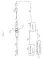
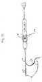
- Fig. 1figure illustrates an overview of a mapping and ablation catheter system in accordance with the present invention.
- the systemincludes a catheter 10 having a shaft portion 12, a control handle 14, and a connector portion 16.
- a controller 8is connected to connector portion 16 via cable 6.
- Ablation energy generator 4may be connected to controller 8 via cable 3.
- a recording device 2may be connected to controller 8 via cable 1.
- controller 8is used to control ablation energy provided by ablation energy generator 4 to catheter 10.
- controller 8is used to process signals coming from catheter 10 and to provide these signals to recording device 2.
- recording device 2, ablation energy generator 4, and controller 8could be incorporated into a single device.
- controller 8may be a QUADRAPULSE RF CONTROLLERTM device available from CR Bard, Inc., Murray Hill, New Jersey.
- the present inventiongenerally includes a catheter and method of its use for mapping and ablation in electrophysiology procedures.
- Catheter 10includes a shaft portion 12, a control handle 14, and a connector portion 16.
- connector portion 16is used to allow signal wires running from the electrodes at the distal portion of the catheter to be connected to a device for processing the electrical signals, such as a recording device.
- Catheter 10may be a steerable device.
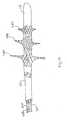
- Fig. 2illustrates the distal tip portion 18 being deflected by the mechanism contained within control handle 14.
- Control handle 14may include a rotatable thumb wheel which can be used by a user to deflect the distal end of the catheter.
- the thumb wheel(or any other suitable actuating device) is connected to one or more pull wires which extend through shaft portion 12 and are connected to the distal end 18 of the catheter at an off-axis location, whereby tension applied to one or more of the pull wires causes the distal portion of the catheter to curve in a predetermined direction or directions.
- U.S. Patent Numbers 5,383,852 , 5,462,527 , and 5,611,777which are hereby incorporated by reference, illustrate various embodiments of control handle 14 that may be used for steering catheter 10.
- Shaft portion 12includes a distal tip portion 18, a first stop 20 and an inner member 22 connected to the first stop portion 20.
- Inner member 22may be a tubular member.
- Concentrically disposed about inner member 22is a first sheath 24 and a second sheath 26.
- Also concentrically disposed about inner member 22is a braided conductive member 28 anchored at respective ends 30 and 32 to the first sheath 24 and the second sheath 26, respectively.
- advancing the second sheath 26 distally over inner member 22causes the first sheath 24 to contact stop 20. Further distal advancement of the second sheath 26 over inner member 22 causes the braided conductive member 28 to expand radially to assume various diameters and/or a conical shape.
- Fig. 3illustrates braided conductive member 28 in an unexpanded (collapsed or "undeployed") configuration.
- Figs. 2 and 4illustrate braided conductive member 28 in a partially expanded condition.
- Fig. 1illustrates braided conductive member 28 radially expanded (“deployed") to form a disk.
- braided conductive member 28can be radially expanded by moving inner member 22 proximally with respect to the second sheath 26.
- inner member 22 and distal tip portion 18may be the same shaft and stop 20 may be removed.
- sheath 24moves over the shaft in response to, for example, a mandrel inside shaft 22 and attached to sheath 24 in the manner described, for example, in U.S. Patent No. 6,178,354 , which is incorporated herein by reference.
- a third sheath 32may be provided.
- the third sheathserves to protect shaft portion 12 and in particular braided conductive member 28 during manipulation through the patient's vasculature.
- the third sheath 32shields braided conductive member 28 from the patient's tissue in the event ablation energy is prematurely delivered to the braided conductive member 28.
- control handle 14may be used.
- U.S. Patent Numbers 5,383,852 , 5,462,527 , and 5,611,777illustrate examples of control handles that can control sheaths 24, 26, and 32.
- control handle 14may include a slide actuator which is axially displaceable relative to the handle. The slide actuator may be connected to one of the sheaths, for example, the second sheath 26 to control the movement of the sheath 26 relative to inner member 22, to drive braided conductive member 28 between respective collapsed and deployed positions, as previously described.
- Control handle 14may also include a second slide actuator or other mechanism coupled to the retractable outer sheath 32 to selectively retract the sheath in a proximal direction with respect to the inner member 22.
- Braided conductive member 28is, in one embodiment of the invention, a plurality of interlaced, electrically conductive filaments 34.
- Braided conductive member 28may be a wire mesh.
- the filamentsare flexible and capable of being expanded radially outwardly from inner member 22.
- the filaments 34are preferably formed of metallic elements having relatively small cross sectional diameters, such that the filaments can be expanded radially outwardly.
- the filamentsmay be round, having a dimension on the order of about 0.001-0.030 inches in diameter.
- the filamentsmay be flat, having a thickness on the order of about 0.001-0.030 inches, and a width on the order of about 0.001-0.030 inches.
- the filamentsmay be formed of Nitinol type wire.
- the filamentsmay include non metallic elements woven with metallic elements, with the non metallic elements providing support to or separation of the metallic elements.
- a multiplicity of individual filaments 34may be provided in braided conductive member 28, for example up to 300
- Each of the filaments 34can be electrically isolated from each other by an insulation coating.
- This insulation coatingmay be, for example, a polyamide type material. A portion of the insulation on the outer circumferential surface 60 of braided conductive member 28 is removed. This allows each of the filaments 34 to form an isolated electrode, not an electrical contact with any other filament, that may be used for mapping and ablation. Alternatively, specific filaments may be permitted to contact each other to form a preselected grouping.
- each of the filaments 34is helically wound under compression about inner member 22.
- the portions of filaments 34 that have had the insulation stripped awaydo not contact adjacent filaments and thus, each filament 34 remains electrically isolated from every other filament.
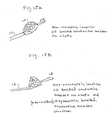
- Fig. 6illustrates how the insulation may be removed from individual filaments 34 while still providing isolation between and among the filaments.
- regions 50illustrate regions, on the outer circumferential surface 60 of braided conductive member 28, where the insulation has been removed from individual filaments 34.
- the insulationmay be removed from up to one half of the outer facing circumference of each of the individual filaments 34 while still retaining electrical isolation between each of the filaments 34.
- each of the filaments 34 that comprise braided conductive member 28may be removed about the outer circumferential surface 60 of braided conductive member 28 in various ways. For example, one or more circumferential bands may be created along the length of braided conductive member 28. Alternatively, individual sectors or quadrants only may have their insulation removed about the circumference of braided conductive member 28. Alternatively, only selected filaments 34 within braided conductive member 28 may have their circumferentially facing insulation removed. Thus, an almost limitless number of configurations of insulation removal about the outer circumferential surface 60 of braided conductive member 28 can be provided depending upon the mapping and ablation characteristics and techniques that a clinician desires.
- the insulation on each of the filaments 34may be removed at the outer circumferential surface 60 of braided conductive member 28 in a variety of ways as long as the insulation is maintained between filaments 34 so that filaments 34 remain electrically isolated from each other.
- the insulationcan be removed from the filaments 34 in a variety of ways to create the stripped portions 50 on braided conductive member 28.
- mechanical meanssuch as abration or scraping may be used.
- a water jet, chemical means, or thermal radiation meansmay be used to remove the insulation.
- braided conductive member 28may be rotated about inner member 22, and a thermal radiation source such as a laser may be used to direct radiation at a particular point along the length of braided conductive member 28. As the braided conductive member 28 is rotated and the thermal radiation source generates heat, the insulation is burned off the particular region.
- a thermal radiation sourcesuch as a laser
- Insulation removalmay also be accomplished by masking selected portions of braided conductive member 28.
- a masksuch as a metal tube may be placed over braided conducive member 28.
- braided conductive member 28may be wrapped in foil or covered with some type of photoresist. The mask is then removed in the areas in which insulation removal is desired by, for example, cutting away the mask, slicing the foil, or removing the photoresist.
- a maskcan be provided that has a predetermined insulation removal pattern. For example, a metal tube having cutouts that, when the metal tube is placed over braided conductive member 28, exposes areas where insulation is to be removed.
- Fig. 6illustrates how thermal radiation 52 may be applied to the outer circumferential surface 56 of a respective filament 34 that defines the outer circumferential surface 60 of braided conductive member 28.
- the insulation 54is burned off or removed from the outer circumference 56 of wire 34 to create a region 58 about the circumference 56 of filament 34 that has no insulation.
- the insulation 54can also be removed in a preferential manner so that a particular portion of the circumferential surface 56 of a filament 34 is exposed.
- the stripped portions of filamentsmay preferentially face the intended direction of mapping or ablation.
- a plurality of individual mapping and ablation channelscan be created.
- a wireruns from each of the filaments 34 within catheter shaft 12 and control handle 14 to connector portion 16.
- a multiplexer or switch boxmay be connected to the conductors so that each filament 34 may be controlled individually. This function may be incorporated into controller 8.
- a number of filaments 34may be grouped together for mapping and ablation. Alternatively, each individual filament 34 can be used as a separate mapping channel for mapping individual electrical activity within a blood vessel at a single point. Using a switch box or multiplexer to configure the signals being received by filaments 34 or ablation energy sent to filaments 34 results in an infinite number of possible combinations of filaments for detecting electrical activity during mapping procedures and for applying energy during an ablation procedure.
- the surface area of the braid that is in contact with a blood vessel wallcan also be controlled. This in turn will allow control of the impedance presented to an ablation energy generator, for example, generator 4.
- selectively removing the insulationcan provide a predetermined or controllable profile of the ablation energy delivered to the tissue.
- filaments 34may be bare wire and insulation can be added to them.
- catheter 10Individual control of the electrical signals received from filaments 34 allows catheter 10 to be used for bipolar (differential or between filament) type mapping as well as unipolar (one filament with respect to a reference) type mapping.
- Catheter 10may also have, as illustrated in Figs. 2 and 3 , a reference electrode 13 mounted on shaft 12 so that reference electrode 13 is located outside the heart during unipolar mapping operations.
- Radiopaque markerscan also be provided for use in electrode orientation and identification.
- inner tubular member 22is a catheter shaft, guide wire, or a hollow tubular structure for introduction of saline, contrast media, heparin or other medicines, or introduction of guidewires, or the like.
- a temperature sensor or sensorssuch as, but not limited to, one or more thermocouples may be attached to braided conductive member 28 for temperature sensing during ablation procedures.
- a plurality of thermocouplesmay also be woven into the braided conductive member 28.
- An individual temperature sensorcould be provided for each of the filaments 34 that comprise braided conductive member 28.
- braided conductive member 28can be constructed of one or more temperature sensors themselves.
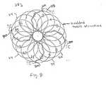
- Fig. 8illustrates braided conductive member 28 in its fully expanded or deployed configuration. Braided conductive member 28 forms a disk when fully expanded. In the embodiment illustrated in Fig. 8 , there are sixteen filaments 34 that make up braided conductive member 28.
- Temperature monitoring or controlcan be incorporated into braided conductive member 28, for example, by placing temperature sensors (such as thermocouples, thermistors, etc.) on the expanded braided conductive member 28 such that they are located on the distally facing ablative ring formed when braided conductive member 28 is in its fully expanded configuration.
- Temperature monitoringrefers to temperature reporting and display for physician interaction.
- Tempoture controlrefers to the capability of adding an algorithm in a feedback loop to titrate power based on temperature readings from the temperature sensors disposed on braided conductive member 28.
- Temperature sensorscan provide a means of temperature control provided the segment of the ablative ring associated with each sensor is independently controllable (e.g., electrically isolated from other regions of the mesh).
- controlcan be achieved by dividing the ablative structure into electrically independent sectors, each with a temperature sensor, or alternatively, each with a mechanism to measure impedance in order to facilitate power titration.
- the ablative structuremay be divided into electrically independent sectors so as to provide zone control. The provision of such sectors can be used to provide power control to various sections of braided conductive member 28.
- FIG. 8four temperature sensors 70 are provided on braided conductive member 28.
- a sectormay include one or more filaments 34.
- energycan be applied to one or more of the filaments 34 in any combination desired depending upon the goals of the ablation procedure.
- a temperature sensorcould be provided on each filament 34 of braided conductive member 28 or shared among one or more filaments. In mapping applications, one or more of the filaments 34 can be grouped together for purposes of measuring electrical activity.
- Fig. 10illustrates a side view of braided conductive member 28 including temperature sensors 70.
- temperature sensors 70emerge from four holes 72. Each hole 72 is disposed in one quadrant of anchor 74.
- the temperature sensors 70are bonded to the outside edge 76 of braided conductive member 28.
- Temperature sensors 70may be isolated by a small piece of polyimide tubing 73 around them and then bonded in place to the filaments.
- the temperature sensors 7may be woven and twisted into braided conductive member 28 or they can be bonded on a side-by-side or parallel manner with the filaments 34.
- the wiresare preferably stripped of their insulative coating in the region forming the ablative ring (when expanded). However, sufficient insulation may be left on the wires in order to prevent interconnection when in the expanded state.
- adjacent mesh wirescan be permitted to touch in their stripped region, but can be separated into groups by fully insulated (unstripped) wires imposed, for example, every 3 or 5 wires apart (the number of wires does not limit this invention), thus forming sectors of independently controllable zones. Each zone can have its own temperature sensor.
- the wirescan be "bundled" (or independently attached) to independent outputs of an ablation energy generator.
- RF energycan then be titrated in its application to each zone by switching power on and off (and applying power to other zones during the 'off period') or by modulating voltage or current to the zone (in the case of independent controllers).
- the temperature inputs from the temperature sensorscan be used in a standard feedback algorithm to control the power delivery.
- braided conductive member 28may be used to support a ribbon-like structure which is separated into discrete sectors.
- the ribbon-like structure 81may be, for example, a pleated copper flat wire that, as braided conductive member 28 expands, unfolds into an annular ring.
- Each of the wires 83a-83dlie in the same plane.
- structure 81may include any number of wires depending upon the application and desired performance.
- Each of wires 83a-83dis insulated. Insulation may then be removed from each wire to create different sectors 85a-85d.
- each of wires 83a-83dmay be uninsulated and insulation may be added to create different sectors.
- the different sectorsprovide an ablative zone comprised of independently controllable wires 83a-83d.
- Temperature sensors 70may be mounted on the individual wires, and filaments 34 may be connected to respective wires 83a-83d to provide independent control of energy to each individual sector.
- each of wires 83a-83dcan have multiple sectors formed by removing insulation in various locations and that numerous combinations of sectors 85a-85d and wires 83a-83d forming ribbon-like structure 81 can be obtained.
- Figs. 11-13illustrate aspects of the steering capabilities of the present invention.
- catheter 10is capable of being steered using control handle 14.
- Fig. 1illustrates steering where the steering pivot or knuckle is disposed on catheter shaft 12 in a region that is distal to the braided conductive member 28.
- Fig. 11illustrates catheter 10 wherein the pivot point or steering knuckle is disposed proximal to braided conductive member 28.
- Fig. 12illustrates catheter 10 having the capability of providing steering knucldes both proximal and distal to braided conductive member 28.
- Figs. 1-2 , and 11-12illustrate two dimensional or single plane type steering.
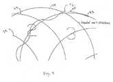
- the catheter of the present inventioncan also be used in connection with a three dimensional steering mechanism.
- the cathetercan be manipulated into a three-dimensional "lasso-like" shape, particularly at the distal end of the catheter.
- the cathetercan have a primary curve 80 in one plane and then a second curve 82 in another plane at an angle to the first plane.
- the cathetercan provide increased access to difficult to reach anatomical structures.
- a target site for a mapping or ablation operationmay be internal to a blood vessel.
- the increased steering capabilitycan allow easier access into the target blood vessel.
- the additional dimension of steeringcan allow for better placement of braided conductive member 28 during an ablation or mapping procedure.
- Catheter 10can be inserted into a site using the steering capabilities provided by primary curve 80. Thereafter, using the secondary curve 82, braided conductive member 28 can be tilted into another plane for better orientation or contact with the target site.
- braided conductive member 28can include from one to 300 or more filaments.
- the filamentsmay vary from very fine wires having small diameters or cross-sectional areas to large wires having relatively large diameters or cross-sectional areas.
- Fig. 14illustrates the use of more than one braided conductive member 28 as the distal end of catheter 10.
- three braided conductive members 28A, 28B, and 28Care provided at the distal end of catheter 10.
- Braided conductive members 28A, 28B, and 29Cmay be, in their expanded conditions, the same size or different sizes.
- Each of the braided conductive members 28A, 28B, and 28Ccan be expanded or contracted independently in the manner illustrated in Figs. 1-4 via independent control shafts 26A, 26B, and 26C.
- the use of multiple braided conductive membersprovides several advantages.
- braided conductive members 28A, 28B, and 28Care of different expanded diameters, than sizing can be done in vivo during a procedure.
- one of the braided conductive memberscan be used for ablation and another of the braided conductive members can be used for mapping. This allows for quickly checking the effectiveness of an ablation procedure.
- braided conductive member 28is generally symmetrical and coaxial with respect to catheter shaft 12.
- certain anatomical structuresmay have complex three-dimensional shapes that are not easily approximated by a geometrically symmetrical mapping or ablation structure.
- This type of structureoccurs at the CS ostium.
- braided conductive member 28can be "preformed" to a close approximation of that anatomy, and yet still be flexible enough to adapt to variations found in specific patients.
- braided conductive member 28can be "preformed” to a close approximation of that anatomy, and be of sufficient strength (as by choice of materials, configuration, etc.) to force the tissue to conform to variations found in specific patients.
- Fig. 15Aillustrates braided conductive member 28 disposed about shaft 12 in an off-center or non concentric manner.
- braided conductive member 28may also be constructed so that the parameter of the braided conductive member in its expanded configuration has a non-circular edge so as to improve tissue contact around the parameter of the braided conductive member.
- 15Billustrates an example of this type of configuration where the braided conductive member 28 is both off center or non concentric with respect to catheter shaft 12 and also, in its deployed or expanded configuration, has an asymmetric shape.
- the eccentricity of braided conductive member 28 with respect to the shaft and the asymmetric deployed configurationscan be produced by providing additional structural supports in braided conductive member 28, for example, such as by adding nitinol, ribbon wire, and so on.
- varying the winding pitch or individual filament size or placement or deforming selective filaments in braided conductive member 28 or any other means known to those skilled in the artmay be used.
- Figs. 16A-16Cillustrate another configuration of braided conductive member 28 and catheter 10. As illustrated in Figs. 16A-16C , the distal tip section of catheter 10 has been removed and braided conductive member 28 is disposed at the distal end of catheter 10. One end of braided conductive member 28 is anchored to catheter shaft 12 using an anchor band 90 that clamps the end 32 of braided conductive member 28 to catheter shaft 12. The other end of braided conductive member 28 is clamped to an activating shaft such as shaft 26 using another anchor band 92.
- Fig. 16Aillustrates braided conductive member 28 in its undeployed configuration. As shaft 26 is moved distally, braided conductive member 28 emerges or everts from shaft 12. As shown in Fig.
- braided conductive member 28has reached its fully deployed diameter and an annular tissue contact zone 29 can be placed against an ostium or other anatomical structure.
- further distal movement of shaft 26can be used to create a concentric locating region 94 that can help to provide for concentric placement within an ostium of a pulmonary vein, for example.
- Concentric locating region 94may be formed by selective variations in the winding density of filaments 34 in braided conductive member 28, preferential predeformation of the filaments, additional eversion of braided conductive member 28 from shaft 12, or by other means known to those skilled in the art.
- braided conductive member 28is composed of one or several large wires 96 rather than a multiplicity of smaller diameter wires.
- the wire or wirescan be moved between the expanded and unexpanded positions in the same manner as illustrated in Fig. 1 .
- a region 98may be provided in which the insulation has been removed for mapping or ablation procedures.
- the single wire or "corkscrew" configurationprovides several advantages. First, the wire or wires do not cross each other and therefore there is only a single winding direction required for manufacture. In addition, the risk of thrombogenicity may be reduced because there is a smaller area of the blood vessel being blocked. In addition the connections between the ends of the large wire and the control shafts may be simplified.
- the catheter 10 of the present inventioncan be coated with a number of coatings that can enhance the operating properties of braided conductive member 28.
- the coatingscan be applied by any of a number of techniques and the coatings may include a wide range of polymers and other materials.
- Braided conductive member 28can be coated to reduce its coefficient of friction, thus reducing the possibility of thrombi adhesion to the braided conductive member as well as the possibility of vascular or atrial damage. These coatings can be combined with the insulation on the filaments that make up braided conductive member 28, these coatings can be included in the insulation itself, or the coatings can be applied on top of the insulation. Examples of coating materials that can be used to improve the lubricity of the catheter include PD slick available from Phelps Dodge Corporation, Ag, Tin, BN. These materials can be applied by an ion beam assisted deposition ("IBAD”) technique developed by, for example. Amp Corporation.
- IBADion beam assisted deposition
- Braided conductive member 28can also be coated to increase or decrease its thermal conduction which can improve the safety or efficacy of the braided conductive member 28. This may be achieved by incorporating thermally conductive elements into the electrical insulation of the filaments that make up braided conductive member 28 or as an added coating to the assembly. Alternatively, thermally insulating elements may be incorporated into the electrical insulation of the filaments that make up braided conductive member 28 or added as a coating to the assembly. Polymer mixing, IBAD, or similar technology could be used to add Ag, Pt, Pd, Au, Ir, Cobalt, and others into the insulation or to coat braided conductive member 28.
- Radioopaque coatings or markerscan also be used to provide a reference point for orientation of braided conductive member 28 when viewed during fluoroscopic imaging.
- the materials that provide radiopacityincluding, for example, Au, Pt, Ir, and other known to those skilled in the art. These materials may be incorporated and used as coatings as described above.
- Antithrombogenic coatingssuch as heparin and BH, can also be applied to braided conductive member 28 to reduce thrombogenicity to prevent blood aggregation on braided conductive member 28. These coatings can be applied by dipping or spraying, for example.
- the filament 34 of braided conductive member 28may be constructed of metal wire materials. These materials may be, for example, MP35N, nitinol, or stainless steel. Filaments 34 may also be composites of these materials in combination with a core of another material such as silver or platinum.
- the combination of a highly conductive electrical core material with another material forming the shell of the wireallows the mechanical properties of the shell material to be combined with the electrical conductivity of the core material to achieve better and/or selectable performance.
- the choice and percentage of core material used in combination with the choice and percentage of shell material usedcan be selected based on the desired performance characteristics and mechanical/electrical properties desired for a particular application.
- the size of a lesion created by radiofrequency (RF) energyis a function of the RF power level and the exposure time.
- the exposure timecan be limited by an increase in impedance that occurs when the temperature at the electrode-tissue interface approaches a 100°C.
- One way of maintaining the temperature less than or equal to this limitis to irrigate the ablation electrode with saline to provide convective cooling so as to control the electrode-tissue interface temperature and thereby prevent an increase in impedance. Accordingly, irrigation of braided conductive member 28 and the tissue site at which a lesion is to be created can be provided in the present invention.
- Irrigation manifold 100is disposed along shaft 22 inside braided conductive member 28.
- Irrigation manifold 100may be one or more polyimid tubes.
- the irrigation manifoldsplits into a number of smaller tubes 102 that are woven into braided conductive member 28 along a respective filament 34.
- a series of holes 104may be provided in each of the tubes 102. These holes can be oriented in any number of ways to target a specific site or portion of braided conductive member 28 for irrigation.
- Irrigation manifold 100runs through catheter shaft 12 and may be connected to an irrigation delivery device outside the patient used to inject an irrigation fluid, such as saline, for example, such as during an ablation procedure.
- the irrigation systemcan also be used to deliver a contrast fluid for verifying location or changes in vessel diameter.
- a contrast mediummay be perfused prior to ablation and then after an ablation procedure to verify that there have been no changes in the blood vessel diameter.
- the contrast mediumcan also be used during mapping procedures to verify placement of braided conductive member 28.
- antithrombogenic fluidssuch as heparin can also be perfused to reduce thrombogenicity.
- Fig. 19illustrates another way of providing perfusion/irrigation in catheter 10.
- the filaments 34 that comprise braided conductive member 28are composed of a composite wire 110.
- the composite wire 110includes an electrically conductive wire 112 that is used for delivering ablation energy in an ablation procedure or for detecting electrical activity during a mapping procedure. Electrical wire 112 is contained within a lumen 114 that also contains a perfusion lumen 116, Perfusion lumen 116 is used to deliver irrigation fluid or a contrast fluid as described in connection with Fig. 18 .
- the insulation 118 surrounding wire filament 112can be stripped away to form an electrode surface.
- perfusion lumen 116Holes can then be provided into perfusion lumen 116 to then allow perfusion at targeted sites along the electrode surface.
- the perfusion lumenscan be connected together to form a manifold which manifold can then be connected to, for example, perfusion tube 120 and connected to a fluid delivery device.
- shroudcan add protection to braided conductive member 28 during insertion and removal of catheter 10.
- a shroudcan also be used to form or shape braided conductive member 28 when in its deployed state.
- Shroudsmay also reduce the risk of thrombi formation on braided conductive member 28 by reducing the area of filament and the number of filament crossings exposed to blood contact. This can be particularly beneficial at the ends 30 and 32 of braided conductive member 28. The density of filaments at ends 30 and 32 is greatest and the ends can therefore be prone to blood aggregation.
- the shroudscan be composed of latex balloon material or any material that would be resistant to thrombi formation durable enough to survive insertion through an introducer system, and would not reduce the mobility of braided conductive member 28.
- the shroudscan also be composed of an RF transparent material that would allow RF energy to pass through the shroud. If an RF transparent material is used, complete encapsulation of braided conductive member 28 is possible.
- a shroud or shroudsmay also be useful when irrigation or perfusion is used, since the shrouds can act to direct irrigation or contrast fluid to a target region.
- Figs. 20A-20Eillustrate various examples of shrouds that may be used in the present invention.
- Fig. 20Aillustrates shrouds 130 and 132 disposed over end regions 31 and 33, respectively, of braided conductive member 28. This configuration can be useful in preventing coagulation of blood at the ends of braided conductive member 28.
- Fig. 20Billustrates shrouds 130 and 132 used in conjunction with an internal shroud 134 contained inside braided conductive member 28. In addition to preventing blood coagulation in regions 31 and 32, the embodiment illustrated in Fig. 20B also prevents blood from entering braided conductive member 28.
- Fig. 20Cillustrates shrouds 130 and 132 being used to direct and irrigation fluid or contrast medium along the circumferential edge of braided conductive member 28.
- perfusioncan be provided as illustrated in Figs. 18 and 19 .
- Fig. 20Dillustrates the use of an external shroud that covers braided conductive member 28.
- Shroud 136completely encases braided conductive member 28 and thereby eliminates blood contact with braided conductive member 28.
- Shroud 136may be constructed of a flexible yet ablation-energy transparent material so that, when used in an ablation procedure, braided conductive member 28 can still deliver energy to a targeted ablation site.
- Fig. 20Ealso illustrates an external shroud 137 encasing braided conductive member 28.
- Shroud 137may also be constructed of a flexible yet ablation-energy transparent material.
- Openings 139may be provided in shroud 137 to allow the portions of braided conductive member 28 that are exposed by the opening to come into contact with tissue. Openings 139 may be elliptical, circular, circumferential, etc.
- catheter 10There may be times during ablation or mapping procedures when catheter 10 is passing through difficult or tortuous vasculature. During these times, it may be helpful to have a guiding sheath through which to pass catheter 10 so as to allow easier passage through the patient's vasculature.
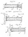
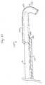
- Fig. 21illustrates one example of a guiding sheath that may be used in connection with catheter 10.
- the guiding sheath 140includes a longitudinal member 142.
- Longitudinal member 142may be constructed of a material rigid enough to be pushed next to catheter shaft 12 as the catheter is threaded through the vasiculature.
- longitudinal member 142may be stainless steel.
- Longitudinal member 142is attached to a sheath 144 disposed at the distal end 146 of longitudinal member 142.
- the split sheath 144may have one or more predetermined curves 148 that are compatible with the shapes of particular blood vessels (arteries or veins) that catheter 10 needs to pass through.
- Split sheath 144may extend proximally along longitudinal member 142.
- sheath 144 and longitudinal member 142may be bonded together for a length of up to 20 or 30 centimeters to allow easier passage through the patient's blood vessels.
- Sheath 144includes a predetermined region 150 that extends longitudinally along sheath 144. Region 150 may be, for example, a seam, that allows sheath 144 to be split open so that the guiding sheath 140 can be pulled back and peeled off catheter shaft 12 in order to remove the sheath.
- longitudinal member 142may be a hypotube or the like having an opening 152 at distal end 146 that communicates with the interior of sheath 144.
- longitudinal member 142can be used to inject irrigation fluid such as saline or a contrast medium for purposes of cooling, flushing, or visualization.
- Figs. 22 , 23 , and 24which figures illustrate how the catheter of the present invention may be used in endocardial and epicardial applications.
- FIG. 22this figure illustrates an endocardial ablation procedure.
- catheter shaft 12is introduced into a patient's heart 150.
- Appropriate imaging guidancedirect visual assessment, camera port, fluoroscopy, echocardiographic, magnetic resonance, etc.
- Fig. 22in particular illustrates catheter shaft 12 being placed in the left atrium of the patient's heart. Once catheter shaft 12 reaches the patient's left atrium, it may then be introduced through an ostium 152 of a pulmonary vein 154.
- braided conductive member 28is then expanded to its deployed position, where, in the illustrated embodiment, braided conductive member 28 forms a disk.
- Catheter shaft 12then advanced further into pulmonary vein 154 until the distal side 156 of braided conductive member 28 makes contact with the ostium of pulmonary vein 154. External pressure may be applied along catheter shaft 12 to achieve the desired level of contact of braided conductive member 28 with the ostium tissue. Energy is then applied to the ostium tissue 152 in contact with braided conductive member 28 to create an annular lesion at or near the ostium.
- the energy usedmay be RF (radiofrequency), DC, microwave, ultrasonic, cryothermal, optical, etc.
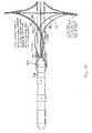
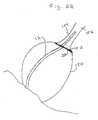
- Fig. 23figure illustrates an epicardial ablation procedure.
- catheter shaft 12is introduced into a patient's thoracic cavity and directed to pulmonary vein 154.
- Catheter 10may be introduced through a trocar port or intraoperatively during open chest surgery Using a steering mechanism, preformed shape, or other means by which to make contact between braided conductive member 128 and the outer surface 158 of pulmonary vein 154, braided conductive member 28 is brought into contact with the outer surface 158 of pulmonary vein 154.
- Appropriate imaging guidancedirect visual assessment, camera port, fluoroscopy, echocardiographic, magnetic resonance, etc.
- imaging guidancedirect visual assessment, camera port, fluoroscopy, echocardiographic, magnetic resonance, etc.
- braided conductive member 28remains in its undeployed or unexpanded condition. External pressure maybe applied to achieve contact between braided conductive member 28 with pulmonary vein 154. Once the desired contact with the outer surface 158 of pulmonary vein 154 is attained, ablation energy is applied to surface 158 via braided conductive member 28 using, for example, RF, DC, ultrasound, microwave, cryothermal, or optical energy. Thereafter, braided conductive member 28 may be moved around the circumference of pulmonary vein 154, and the ablation procedure repeated. This procedure may be used to create, for example, an annular lesion at or near the ostium.
- Fig. 24figure illustrates an endocardial mapping procedure.
- catheter shaft 12is introduced into pulmonary vein 154 in the manner described in connection with Fig. 22 .
- braided conductive 28is expanded as described in connection with, for example, Figs. 2-5 until filaments 34 contact the inner wall 160 of pulmonary vein 154.
- electrical activity within pulmonary vein 154may be detected, measured, and recorded by an external device connected to the filaments 34 of braided conductive member 28.
- Access to the patient's heartcan be accomplished via percutaneous, vascular, surgical (e.g. open-chest surgery), or transthoracic approaches for either endocardial or epicardial mapping and/or mapping and ablation procedures.
- percutaneous, vascular, surgicale.g. open-chest surgery
- transthoracic approachesfor either endocardial or epicardial mapping and/or mapping and ablation procedures.
- the present inventionis thus able to provide an electrophysiology catheter capable of mapping and/or mapping and ablation operations.
- the catheter of the inventionmay be used to provide high density maps of a tissue region because electrocardiograms may be obtained from individual filaments 34 in braided conductive member 28 in either a bipolar or unipolar mode.
- the shape of the electrode regioncan be adjusted by controlling the radial expansion of braided conductive member 28 so as to improve conformity with the patient's tissue or to provide a desired mapping or ablation profile.
- braided conductive member 28may be fabricated of a material of sufficient flexural strength so that the tissue is preferentially conformed to match the expanded or partially expanded shape of the braided conductive member 28.
- the catheter of the present inventionmay be used for mapping procedures, ablation procedures, and temperature measurement and control on the distal and/or proximal facing sides of braided conductive member 28 in its fully expanded positions as illustrated in, for example, Fig. 1 .
- the catheter of the present inventioncan be used to perform "radial" mapping procedures, ablation procedures, and temperature measurement and control. That is, the outer circumferential edge 76, illustrated, for example, in Fig. 8 , can be applied against an inner circumferential surface of a blood vessel.
- mapping and ablation procedureshas the potential to reduce procedure time and reduce X-ray exposure.
- the ability to expand braided conductive member 28 in an artery or vein against a tissue structure such as a freewall or ostiumcan provide good contact pressure for multiple electrodes and can provide an anatomical anchor for stability. Temperature sensors can be positioned definitively against the endocardium to provide good thermal conduction to the tissue. Lesions can be selectively produced at various sections around the circumference of braided conductive member 28 without having to reposition catheter 10. This can provide more accurate lesion placement within the artery or vein.
- Braided conductive member 28 in its radially expanded position as illustrated in particular in Figs. 1 and 8is advantageous because, in these embodiments, it does not block the blood vessel during a mapping or ablation procedure, but allows blood flow through the braided conductive member thus allowing for longer mapping and/or ablation times, which can potentially improve accuracy of mapping and efficacy of lesion creation.
Landscapes
- Health & Medical Sciences (AREA)
- Surgery (AREA)
- Life Sciences & Earth Sciences (AREA)
- Engineering & Computer Science (AREA)
- Molecular Biology (AREA)
- Animal Behavior & Ethology (AREA)
- Otolaryngology (AREA)
- Plasma & Fusion (AREA)
- Physics & Mathematics (AREA)
- Biomedical Technology (AREA)
- Heart & Thoracic Surgery (AREA)
- Medical Informatics (AREA)
- Cardiology (AREA)
- Nuclear Medicine, Radiotherapy & Molecular Imaging (AREA)
- General Health & Medical Sciences (AREA)
- Public Health (AREA)
- Veterinary Medicine (AREA)
- Surgical Instruments (AREA)
- Measuring And Recording Apparatus For Diagnosis (AREA)
- Measurement And Recording Of Electrical Phenomena And Electrical Characteristics Of The Living Body (AREA)
- Media Introduction/Drainage Providing Device (AREA)
- Investigating Or Analyzing Materials By The Use Of Electric Means (AREA)
- Ultra Sonic Daignosis Equipment (AREA)
- Electrotherapy Devices (AREA)
Abstract
Description
- The invention relates to medical devices for performing mapping and ablation procedures. More particularly, the invention relates to methods and apparatus for mapping and ablating at or near the ostia of the pulmonary veins or coronary sinus.
- The human heart is a very complex organ, which relies on both muscle contraction and electrical impulses to function properly. The electrical impulses travel through the heart walls, first through the atria and then the ventricles, causing the corresponding muscle tissue in the atria and ventricles to contract. Thus, the atria contract first, followed by the ventricles. This order is essential for proper functioning of the heart.
- Over time, the electrical impulses traveling through the heart can begin to travel in improper directions, thereby causing the heart chambers to contract at improper times. Such a condition is generally termed a cardiac arrhythmia, and can take many different forms. When the chambers contract at improper times, the amount of blood pumped by the heart decreases, which can result in premature death of the person.
- Techniques have been developed which are used to locate cardiac regions responsible for the cardiac arrhythmia, and also to disable the short-circuit function of these areas. According to these techniques, electrical energy is applied to a portion of the heart tissue to ablate that tissue and produce scars which interrupt the reentrant conduction pathways or terminate the focal initiation. The regions to be ablated are usually first determined by endocardial mapping techniques. Mapping typically involves percutaneously introducing a catheter having one or more electrodes into the patient, passing the catheter through a blood vessel (e.g. the femoral vein or artery) and into an endocardial site (e.g., the atrium or ventricle of the heart), and deliberately inducing an arrhythmia so that a continuous, simultaneous recording can be made with a multichannel recorder at each of several different endocardial positions. When an arrythormogenic focus or inappropriate circuit is located, as indicated in the electrocardiogram recording, it is marked by various imaging or localization means so that cardiac arrhythmias emanating from that region can be blocked by ablating tissue. An ablation catheter with one or more electrodes can then transmit electrical energy to the tissue adjacent the electrode to create a lesion in the tissue. One or more suitably positioned lesions will typically create a region of necrotic tissue which serves to disable the propagation of the errant impulse caused by the arrythromogenic focus. Ablation is carried out by applying energy to the catheter electrodes. The ablation energy can be, for example, RF, DC, ultrasound, microwave, or laser radiation.
- Atrial fibrillation together with atrial flutter are the most common sustained arrhythmias found in clinical practice.
- Current understanding is that atrial fibrillation is frequently initiated by a focal trigger from the orifice of or within one of the pulmonary veins. Though mapping and ablation of these triggers appears to be curative in patients with paroxysmal atrial fibrillation, there are a number of limitations to ablating focal triggers via mapping and ablating the earliest site of activation with a "point" radiofrequency lesion. One way to circumvent these limitations is to determine precisely the point of earliest activation. Once the point of earliest activation is identified, a lesion can be generated to electrically , isolate the trigger with a lesion; firing from within those veins would then be eliminated or unable to reach the body of the atrium, and thus could not trigger atrial fibrillation.
- Another method to treat focal arrhythmias is to create a continuous, annular lesion around the ostia (i.e., the openings) of either the veins or the arteries leading to or from the atria thus "corralling" the signals emanating from any points distal to the annular lesion. Conventional techniques include applying multiple point sources around the ostia in an effort to create such a continuous lesion. Such a technique is relatively involved, and requires significant skill and attention from the clinician performing the procedures.
- Another source of arrhythmias may be from reentrant circuits in the myocardium itself. Such circuits may not necessarily be associated with vessel ostia, but may be interrupted by means of ablating tissue either within the circuit or circumscribing the region of the circuit. It should be noted that a complete 'fence' around a circuit or tissue region is not always required in order to block the propagation of the arrhythmia; in many cases simply increasing the propagation path length for a signal may be sufficient. Conventional means for establishing such lesion 'fences' include a multiplicity of point-by-point lesions, dragging a single electrode across tissue while delivering energy, or creating an enormous lesion intended to inactivate a substantive volume of myocardial tissue.
- Commonly-owned
U.S. Patent Application No. 09/396,502 , entitled Apparatus For Creating A Continuous Annular Lesion, which is hereby incorporated by reference, discloses a medical device which is capable of ablating a continuous ring of tissue around the ostia of either veins or arteries leading to or from the atria. - The present invention encompasses apparatus and methods for mapping electrical activity within the heart. The present invention also encompasses methods and apparatus for creating lesions in the heart tissue (ablating) to create a region of necrotic tissue which serves to disable the propagation of errant electrical impulses caused by an arrhythmia.
- In one embodiment, the present invention includes a medical device including a catheter having a braided conductive member at a distal end thereof, a mechanism for expanding the braided conductive member from an undeployed to a deployed position, and a mechanism for applying energy via the braided conductive member to blood vessel.
- In one embodiment, the medical device further includes a mechanism for irrigating the braided conductive member.
- In another embodiment, the medical device further includes at least one reference electrode disposed on a shaft of the catheter.
- In another embodiment, the medical device includes a mechanism for controlling the energy supplied to the braided conductive member.
- In another embodiment, the medical device further includes a mechanism for covering at least a portion of the braided conductive member when the braided conductive member is in the deployed position.
- In another embodiment, at least a portion of the braided conductive member has a coating applied thereto.
- In another embodiment, the medical device includes a mechanism for measuring temperature.
- In another embodiment, the medical device includes a mechanism for steering the catheter.
- The invention also includes a method for treating cardiac arrhythmia, including the steps of introducing a catheter having a braided conductive member at a distal end thereof into a blood vessel, expanding the braided conductive member at a selected location in the blood vessel so that the braided conductive member contacts a wall of the blood vessel, and applying energy to the wall of the blood vessel via the braided conductive member to create a lesion in the blood vessel.
- In another embodiment, the invention includes a method for treating cardiac arrhythmia, including the steps of introducing a catheter into a thoracic cavity of a patient, the catheter having a braided conductive member at a distal end thereof, contacting an exterior wall of a blood vessel in a vicinity of an ostium with the braided conductive member, and applying energy to the blood vessel via the braided conductive member to create a lesion on the exterior wall of the blood vessel.
- The braided conductive member may be a wire mesh.
- The features and advantages of the present invention will be more readily understood and apparent from the following detailed description of the invention, which should be read in conjunction with the accompanying drawings, and from the claims which are appended at the end of the Detailed Description.
- In the drawings, which are incorporated herein by reference and in which like elements have been given like references characters,
Figure 1 illustrates an overview of a mapping and ablation catheter system in accordance with the present invention;Figures 2 and 3 illustrate further details of the catheter illustrated inFigure 1 ;Figures 4-7 illustrate further details of the braided conductive member illustrated inFigures 2 and 3 ;Figures 8-10A illustrate, among other things, temperature sensing in the present invention;Figures 11-13 illustrate further details of the steering capabilities of the present invention;Figures 14-17 illustrate further embodiments of the braided conductive member;Figures 18-19 illustrate the use of irrigation in connection with the present invention;Figures 20A-20E illustrate the use of shrouds in the present invention;Figure 21 illustrates a guiding sheath that may be used in connection with the present invention; andFigures 22-24 illustrate methods of using the present invention.- Reference is now made to
Fig. 1 , which figure illustrates an overview of a mapping and ablation catheter system in accordance with the present invention. The system includes acatheter 10 having ashaft portion 12, acontrol handle 14, and aconnector portion 16. Acontroller 8 is connected toconnector portion 16 via cable 6.Ablation energy generator 4 may be connected tocontroller 8 via cable 3. Arecording device 2 may be connected tocontroller 8 viacable 1. When used in an ablation application,controller 8 is used to control ablation energy provided byablation energy generator 4 tocatheter 10. When used in a mapping application,controller 8 is used to process signals coming fromcatheter 10 and to provide these signals torecording device 2. Although illustrated as separate devices,recording device 2,ablation energy generator 4, andcontroller 8 could be incorporated into a single device. In one embodiment,controller 8 may be a QUADRAPULSE RF CONTROLLER™ device available from CR Bard, Inc., Murray Hill, New Jersey. - In this description, various aspects and features of the present invention will be described. The various features of the invention are discussed separately for clarity. One skilled in the art will appreciate that the features may be selectively combined in a device depending upon the particular application. Furthermore, any of the various features may be incorporated in a catheter and associated method of use for either mapping or ablation procedures.
- Reference is now made to
Figs 2-7 , which figures illustrate one embodiment of the present invention. The present invention generally includes a catheter and method of its use for mapping and ablation in electrophysiology procedures.Catheter 10 includes ashaft portion 12, acontrol handle 14, and aconnector portion 16. When used in mapping applications,connector portion 16 is used to allow signal wires running from the electrodes at the distal portion of the catheter to be connected to a device for processing the electrical signals, such as a recording device. Catheter 10 may be a steerable device.Fig. 2 illustrates thedistal tip portion 18 being deflected by the mechanism contained within control handle 14. Control handle 14 may include a rotatable thumb wheel which can be used by a user to deflect the distal end of the catheter. The thumb wheel (or any other suitable actuating device) is connected to one or more pull wires which extend throughshaft portion 12 and are connected to thedistal end 18 of the catheter at an off-axis location, whereby tension applied to one or more of the pull wires causes the distal portion of the catheter to curve in a predetermined direction or directions.U.S. Patent Numbers 5,383,852 ,5,462,527 , and5,611,777 , which are hereby incorporated by reference, illustrate various embodiments of control handle 14 that may be used for steeringcatheter 10.Shaft portion 12 includes adistal tip portion 18, afirst stop 20 and aninner member 22 connected to thefirst stop portion 20.Inner member 22 may be a tubular member. Concentrically disposed aboutinner member 22 is afirst sheath 24 and asecond sheath 26. Also concentrically disposed aboutinner member 22 is a braidedconductive member 28 anchored at respective ends 30 and 32 to thefirst sheath 24 and thesecond sheath 26, respectively.- In operation, advancing the
second sheath 26 distally overinner member 22 causes thefirst sheath 24 to contactstop 20. Further distal advancement of thesecond sheath 26 overinner member 22 causes the braidedconductive member 28 to expand radially to assume various diameters and/or a conical shape.Fig. 3 illustrates braidedconductive member 28 in an unexpanded (collapsed or "undeployed") configuration.Figs. 2 and4 illustrate braidedconductive member 28 in a partially expanded condition.Fig. 1 illustrates braidedconductive member 28 radially expanded ("deployed") to form a disk. - Alternatively, braided
conductive member 28 can be radially expanded by movinginner member 22 proximally with respect to thesecond sheath 26. - As another alternative,
inner member 22 anddistal tip portion 18 may be the same shaft and stop 20 may be removed. In this configuration,sheath 24 moves over the shaft in response to, for example, a mandrel insideshaft 22 and attached tosheath 24 in the manner described, for example, inU.S. Patent No. 6,178,354 , which is incorporated herein by reference. - As illustrated particularly in
Figs 4 and 5 athird sheath 32 may be provided. The third sheath serves to protectshaft portion 12 and in particular braidedconductive member 28 during manipulation through the patient's vasculature. In addition, thethird sheath 32 shields braidedconductive member 28 from the patient's tissue in the event ablation energy is prematurely delivered to the braidedconductive member 28. - The
respective sheaths inner member 22, which may be a tubular member, in many different manners. Control handle 14 may be used.U.S. Patent Numbers 5,383,852 ,5,462,527 , and5,611,777 illustrate examples of control handles that can controlsheaths second sheath 26 to control the movement of thesheath 26 relative toinner member 22, to drive braidedconductive member 28 between respective collapsed and deployed positions, as previously described. Control handle 14 may also include a second slide actuator or other mechanism coupled to the retractableouter sheath 32 to selectively retract the sheath in a proximal direction with respect to theinner member 22. - Braided
conductive member 28 is, in one embodiment of the invention, a plurality of interlaced, electricallyconductive filaments 34. Braidedconductive member 28 may be a wire mesh. The filaments are flexible and capable of being expanded radially outwardly frominner member 22. Thefilaments 34 are preferably formed of metallic elements having relatively small cross sectional diameters, such that the filaments can be expanded radially outwardly. The filaments may be round, having a dimension on the order of about 0.001-0.030 inches in diameter. Alternatively, the filaments may be flat, having a thickness on the order of about 0.001-0.030 inches, and a width on the order of about 0.001-0.030 inches. The filaments may be formed of Nitinol type wire. Alternatively, the filaments may include non metallic elements woven with metallic elements, with the non metallic elements providing support to or separation of the metallic elements. A multiplicity ofindividual filaments 34 may be provided in braidedconductive member 28, for example up to 300 or more filaments. - Each of the
filaments 34 can be electrically isolated from each other by an insulation coating. This insulation coating may be, for example, a polyamide type material. A portion of the insulation on the outer circumferential surface 60 of braidedconductive member 28 is removed. This allows each of thefilaments 34 to form an isolated electrode, not an electrical contact with any other filament, that may be used for mapping and ablation. Alternatively, specific filaments may be permitted to contact each other to form a preselected grouping. - Each of the
filaments 34 is helically wound under compression aboutinner member 22. As a result of this helical construction, upon radial expansion of braidedconductive member 28, the portions offilaments 34 that have had the insulation stripped away do not contact adjacent filaments and thus, eachfilament 34 remains electrically isolated from every other filament.Fig. 6 , in particular, illustrates how the insulation may be removed fromindividual filaments 34 while still providing isolation between and among the filaments. As illustrated inFig. 6 ,regions 50 illustrate regions, on the outer circumferential surface 60 of braidedconductive member 28, where the insulation has been removed fromindividual filaments 34. In one embodiment of the invention, the insulation may be removed from up to one half of the outer facing circumference of each of theindividual filaments 34 while still retaining electrical isolation between each of thefilaments 34. - The insulation on each of the
filaments 34 that comprise braidedconductive member 28 may be removed about the outer circumferential surface 60 of braidedconductive member 28 in various ways. For example, one or more circumferential bands may be created along the length of braidedconductive member 28. Alternatively, individual sectors or quadrants only may have their insulation removed about the circumference of braidedconductive member 28. Alternatively, only selectedfilaments 34 within braidedconductive member 28 may have their circumferentially facing insulation removed. Thus, an almost limitless number of configurations of insulation removal about the outer circumferential surface 60 of braidedconductive member 28 can be provided depending upon the mapping and ablation characteristics and techniques that a clinician desires. - The insulation on each of the
filaments 34 may be removed at the outer circumferential surface 60 of braidedconductive member 28 in a variety of ways as long as the insulation is maintained betweenfilaments 34 so thatfilaments 34 remain electrically isolated from each other. - The insulation can be removed from the
filaments 34 in a variety of ways to create the strippedportions 50 on braidedconductive member 28. For example, mechanical means such as abration or scraping may be used. In addition, a water jet, chemical means, or thermal radiation means may be used to remove the insulation. - In one example of insulation removal, braided
conductive member 28 may be rotated aboutinner member 22, and a thermal radiation source such as a laser may be used to direct radiation at a particular point along the length of braidedconductive member 28. As the braidedconductive member 28 is rotated and the thermal radiation source generates heat, the insulation is burned off the particular region. - Insulation removal may also be accomplished by masking selected portions of braided
conductive member 28. A mask, such as a metal tube may be placed over braidedconducive member 28. Alternatively, braidedconductive member 28 may be wrapped in foil or covered with some type of photoresist. The mask is then removed in the areas in which insulation removal is desired by, for example, cutting away the mask, slicing the foil, or removing the photoresist. Alternatively, a mask can be provided that has a predetermined insulation removal pattern. For example, a metal tube having cutouts that, when the metal tube is placed over braidedconductive member 28, exposes areas where insulation is to be removed. Fig. 6 illustrates howthermal radiation 52 may be applied to the outercircumferential surface 56 of arespective filament 34 that defines the outer circumferential surface 60 of braidedconductive member 28. Asthermal radiation 52 is applied, theinsulation 54 is burned off or removed from theouter circumference 56 ofwire 34 to create aregion 58 about thecircumference 56 offilament 34 that has no insulation.- The
insulation 54 can also be removed in a preferential manner so that a particular portion of thecircumferential surface 56 of afilament 34 is exposed. Thus, when braidedconductive member 28 is radially expanded, the stripped portions of filaments may preferentially face the intended direction of mapping or ablation. - With the insulation removed from the portions of
filaments 34 on the outer circumferential surface 60 of braidedconductive member 28, a plurality of individual mapping and ablation channels can be created. A wire runs from each of thefilaments 34 withincatheter shaft 12 and control handle 14 toconnector portion 16. A multiplexer or switch box may be connected to the conductors so that eachfilament 34 may be controlled individually. This function may be incorporated intocontroller 8. A number offilaments 34 may be grouped together for mapping and ablation. Alternatively, eachindividual filament 34 can be used as a separate mapping channel for mapping individual electrical activity within a blood vessel at a single point. Using a switch box or multiplexer to configure the signals being received byfilaments 34 or ablation energy sent tofilaments 34 results in an infinite number of possible combinations of filaments for detecting electrical activity during mapping procedures and for applying energy during an ablation procedure. - By controlling the amount of insulation that is removed from the
filaments 34 that comprise braidedconductive member 28, the surface area of the braid that is in contact with a blood vessel wall can also be controlled. This in turn will allow control of the impedance presented to an ablation energy generator, for example,generator 4. In addition, selectively removing the insulation can provide a predetermined or controllable profile of the ablation energy delivered to the tissue. - The above description illustrates how insulation may be removed from a
filaments 34. Alternatively, the same features and advantages can be achieved by adding insulation tofilaments 34. For example,filaments 34 may be bare wire and insulation can be added to them. - Individual control of the electrical signals received from
filaments 34 allowscatheter 10 to be used for bipolar (differential or between filament) type mapping as well as unipolar (one filament with respect to a reference) type mapping. Catheter 10 may also have, as illustrated inFigs. 2 and 3 , areference electrode 13 mounted onshaft 12 so thatreference electrode 13 is located outside the heart during unipolar mapping operations.- Radiopaque markers can also be provided for use in electrode orientation and identification.
- One skilled in the art will appreciate all of the insulation can be removed from
filaments 34 to create a large ablation electrode. - Although a complete catheter steerable structure has been illustrated, the invention can also be adapted so that inner
tubular member 22 is a catheter shaft, guide wire, or a hollow tubular structure for introduction of saline, contrast media, heparin or other medicines, or introduction of guidewires, or the like. - A temperature sensor or sensors, such as, but not limited to, one or more thermocouples may be attached to braided
conductive member 28 for temperature sensing during ablation procedures. A plurality of thermocouples may also be woven into the braidedconductive member 28. An individual temperature sensor could be provided for each of thefilaments 34 that comprise braidedconductive member 28. Alternatively, braidedconductive member 28 can be constructed of one or more temperature sensors themselves. Fig. 8 illustrates braidedconductive member 28 in its fully expanded or deployed configuration. Braidedconductive member 28 forms a disk when fully expanded. In the embodiment illustrated inFig. 8 , there are sixteenfilaments 34 that make up braidedconductive member 28.- Temperature monitoring or control can be incorporated into braided
conductive member 28, for example, by placing temperature sensors (such as thermocouples, thermistors, etc.) on the expanded braidedconductive member 28 such that they are located on the distally facing ablative ring formed when braidedconductive member 28 is in its fully expanded configuration. "Temperature monitoring" refers to temperature reporting and display for physician interaction. "Temperature control" refers to the capability of adding an algorithm in a feedback loop to titrate power based on temperature readings from the temperature sensors disposed on braidedconductive member 28. Temperature sensors can provide a means of temperature control provided the segment of the ablative ring associated with each sensor is independently controllable (e.g., electrically isolated from other regions of the mesh). For example, control can be achieved by dividing the ablative structure into electrically independent sectors, each with a temperature sensor, or alternatively, each with a mechanism to measure impedance in order to facilitate power titration. The ablative structure may be divided into electrically independent sectors so as to provide zone control. The provision of such sectors can be used to provide power control to various sections of braidedconductive member 28. - As illustrated in
Fig. 8 , fourtemperature sensors 70 are provided on braidedconductive member 28. As noted previously, since theindividual filaments 34 in braidedconductive member 28 are insulated from each other, a number of independent sectors may be provided. A sector may include one ormore filaments 34. During ablation procedures, energy can be applied to one or more of thefilaments 34 in any combination desired depending upon the goals of the ablation procedure. A temperature sensor could be provided on eachfilament 34 of braidedconductive member 28 or shared among one or more filaments. In mapping applications, one or more of thefilaments 34 can be grouped together for purposes of measuring electrical activity. These sectoring functions can be provided incontroller 8. Fig. 10 illustrates a side view of braidedconductive member 28 includingtemperature sensors 70. As shown inFig. 10 ,temperature sensors 70 emerge from fourholes 72. Eachhole 72 is disposed in one quadrant ofanchor 74. Thetemperature sensors 70 are bonded to theoutside edge 76 of braidedconductive member 28.Temperature sensors 70 may be isolated by a small piece ofpolyimide tubing 73 around them and then bonded in place to the filaments. The temperature sensors 7 may be woven and twisted into braidedconductive member 28 or they can be bonded on a side-by-side or parallel manner with thefilaments 34.- There are several methods of implementing electrically independent sectors. In one embodiment, the wires are preferably stripped of their insulative coating in the region forming the ablative ring (when expanded). However, sufficient insulation may be left on the wires in order to prevent interconnection when in the expanded state. Alternatively, adjacent mesh wires can be permitted to touch in their stripped region, but can be separated into groups by fully insulated (unstripped) wires imposed, for example, every 3 or 5 wires apart (the number of wires does not limit this invention), thus forming sectors of independently controllable zones. Each zone can have its own temperature sensor. The wires can be "bundled" (or independently attached) to independent outputs of an ablation energy generator. RF energy can then be titrated in its application to each zone by switching power on and off (and applying power to other zones during the 'off period') or by modulating voltage or current to the zone (in the case of independent controllers). In either case, the temperature inputs from the temperature sensors can be used in a standard feedback algorithm to control the power delivery.
- Alternatively, as illustrated in
Figure 10A , braidedconductive member 28 may be used to support a ribbon-like structure which is separated into discrete sectors. As shown inFigure 10A , the ribbon-like structure 81 may be, for example, a pleated copper flat wire that, as braidedconductive member 28 expands, unfolds into an annular ring. Each of the wires 83a-83d lie in the same plane. Although four wires are illustrated inFigure 10A ,structure 81 may include any number of wires depending upon the application and desired performance. Each of wires 83a-83d is insulated. Insulation may then be removed from each wire to create different sectors 85a-85d. Alternatively, each of wires 83a-83d may be uninsulated and insulation may be added to create different sectors. The different sectors provide an ablative zone comprised of independently controllable wires 83a-83d.Temperature sensors 70 may be mounted on the individual wires, andfilaments 34 may be connected to respective wires 83a-83d to provide independent control of energy to each individual sector. One skilled in the art will appreciate that each of wires 83a-83d can have multiple sectors formed by removing insulation in various locations and that numerous combinations of sectors 85a-85d and wires 83a-83d forming ribbon-like structure 81 can be obtained. - Reference is now made to
Figs. 11-13 which illustrate aspects of the steering capabilities of the present invention. As illustrated inFigs. 1-2 ,catheter 10 is capable of being steered usingcontrol handle 14. In particular,Fig. 1 illustrates steering where the steering pivot or knuckle is disposed oncatheter shaft 12 in a region that is distal to the braidedconductive member 28. Fig. 11 illustratescatheter 10 wherein the pivot point or steering knuckle is disposed proximal to braidedconductive member 28.Fig. 12 illustratescatheter 10 having the capability of providing steering knucldes both proximal and distal to braidedconductive member 28.Figs. 1-2 , and11-12 illustrate two dimensional or single plane type steering. The catheter of the present invention can also be used in connection with a three dimensional steering mechanism. For example, using the control handle in the incorporated by reference '852 patent, the catheter can be manipulated into a three-dimensional "lasso-like" shape, particularly at the distal end of the catheter. As shown inFig. 13 , the catheter can have a primary curve 80 in one plane and then asecond curve 82 in another plane at an angle to the first plane. With this configuration, the catheter can provide increased access to difficult to reach anatomical structures. For example, a target site for a mapping or ablation operation may be internal to a blood vessel. Thus, the increased steering capability can allow easier access into the target blood vessel. In addition, the additional dimension of steering can allow for better placement of braidedconductive member 28 during an ablation or mapping procedure.Catheter 10 can be inserted into a site using the steering capabilities provided by primary curve 80. Thereafter, using thesecondary curve 82, braidedconductive member 28 can be tilted into another plane for better orientation or contact with the target site.- Reference is now made to
Figs. 14-17 which figures illustrate other configurations of braidedconductive member 28. As has been described above and will be described in more detail, braidedconductive member 28 can include from one to 300 or more filaments. The filaments may vary from very fine wires having small diameters or cross-sectional areas to large wires having relatively large diameters or cross-sectional areas. Fig. 14 illustrates the use of more than one braidedconductive member 28 as the distal end ofcatheter 10. As shown inFig. 14 , three braidedconductive members catheter 10. Braidedconductive members conductive members Figs. 1-4 viaindependent control shafts 26A, 26B, and 26C. The use of multiple braided conductive members provides several advantages. Rather than having to estimate or guess as to the size of the blood vessel prior to starting a mapping or ablation procedure, if braidedconductive members - Reference is now made to
Fig. 15A and 15B , which figures illustrate other shapes of braidedconductive member 28. As described up to this point, braidedconductive member 28 is generally symmetrical and coaxial with respect tocatheter shaft 12. However, certain anatomical structures may have complex three-dimensional shapes that are not easily approximated by a geometrically symmetrical mapping or ablation structure. One example of this type of structure occurs at the CS ostium. To successfully contact these types of anatomical structures, braidedconductive member 28 can be "preformed" to a close approximation of that anatomy, and yet still be flexible enough to adapt to variations found in specific patients. Alternatively, braidedconductive member 28 can be "preformed" to a close approximation of that anatomy, and be of sufficient strength (as by choice of materials, configuration, etc.) to force the tissue to conform to variations found in specific patients. For exampleFig. 15A illustrates braidedconductive member 28 disposed aboutshaft 12 in an off-center or non concentric manner. In addition, braidedconductive member 28 may also be constructed so that the parameter of the braided conductive member in its expanded configuration has a non-circular edge so as to improve tissue contact around the parameter of the braided conductive member.Fig. 15B illustrates an example of this type of configuration where the braidedconductive member 28 is both off center or non concentric with respect tocatheter shaft 12 and also, in its deployed or expanded configuration, has an asymmetric shape. The eccentricity of braidedconductive member 28 with respect to the shaft and the asymmetric deployed configurations can be produced by providing additional structural supports in braidedconductive member 28, for example, such as by adding nitinol, ribbon wire, and so on. In addition, varying the winding pitch or individual filament size or placement or deforming selective filaments in braidedconductive member 28 or any other means known to those skilled in the art may be used. Figs. 16A-16C illustrate another configuration of braidedconductive member 28 andcatheter 10. As illustrated inFigs. 16A-16C , the distal tip section ofcatheter 10 has been removed and braidedconductive member 28 is disposed at the distal end ofcatheter 10. One end of braidedconductive member 28 is anchored tocatheter shaft 12 using ananchor band 90 that clamps theend 32 of braidedconductive member 28 tocatheter shaft 12. The other end of braidedconductive member 28 is clamped to an activating shaft such asshaft 26 using anotheranchor band 92.Fig. 16A illustrates braidedconductive member 28 in its undeployed configuration. Asshaft 26 is moved distally, braidedconductive member 28 emerges or everts fromshaft 12. As shown inFig. 16B , braidedconductive member 28 has reached its fully deployed diameter and an annulartissue contact zone 29 can be placed against an ostium or other anatomical structure. As illustrated inFig. 16C , further distal movement ofshaft 26 can be used to create a concentric locating region 94 that can help to provide for concentric placement within an ostium of a pulmonary vein, for example. Concentric locating region 94 may be formed by selective variations in the winding density offilaments 34 in braidedconductive member 28, preferential predeformation of the filaments, additional eversion of braidedconductive member 28 fromshaft 12, or by other means known to those skilled in the art.- Reference is now made to
Fig. 17 , which figure illustrates a further embodiment of braidedconductive member 28. As illustrated inFig. 17 , braidedconductive member 28 is composed of one or several large wires 96 rather than a multiplicity of smaller diameter wires. The wire or wires can be moved between the expanded and unexpanded positions in the same manner as illustrated inFig. 1 . In addition, aregion 98 may be provided in which the insulation has been removed for mapping or ablation procedures. The single wire or "corkscrew" configuration provides several advantages. First, the wire or wires do not cross each other and therefore there is only a single winding direction required for manufacture. In addition, the risk of thrombogenicity may be reduced because there is a smaller area of the blood vessel being blocked. In addition the connections between the ends of the large wire and the control shafts may be simplified. - The
catheter 10 of the present invention can be coated with a number of coatings that can enhance the operating properties of braidedconductive member 28. The coatings can be applied by any of a number of techniques and the coatings may include a wide range of polymers and other materials. - Braided
conductive member 28 can be coated to reduce its coefficient of friction, thus reducing the possibility of thrombi adhesion to the braided conductive member as well as the possibility of vascular or atrial damage. These coatings can be combined with the insulation on the filaments that make up braidedconductive member 28, these coatings can be included in the insulation itself, or the coatings can be applied on top of the insulation. Examples of coating materials that can be used to improve the lubricity of the catheter include PD slick available from Phelps Dodge Corporation, Ag, Tin, BN. These materials can be applied by an ion beam assisted deposition ("IBAD") technique developed by, for example. Amp Corporation. - Braided
conductive member 28 can also be coated to increase or decrease its thermal conduction which can improve the safety or efficacy of the braidedconductive member 28. This may be achieved by incorporating thermally conductive elements into the electrical insulation of the filaments that make up braidedconductive member 28 or as an added coating to the assembly. Alternatively, thermally insulating elements may be incorporated into the electrical insulation of the filaments that make up braidedconductive member 28 or added as a coating to the assembly. Polymer mixing, IBAD, or similar technology could be used to add Ag, Pt, Pd, Au, Ir, Cobalt, and others into the insulation or to coat braidedconductive member 28. - Radioopaque coatings or markers can also be used to provide a reference point for orientation of braided
conductive member 28 when viewed during fluoroscopic imaging. The materials that provide radiopacity including, for example, Au, Pt, Ir, and other known to those skilled in the art. These materials may be incorporated and used as coatings as described above. - Antithrombogenic coatings, such as heparin and BH, can also be applied to braided
conductive member 28 to reduce thrombogenicity to prevent blood aggregation on braidedconductive member 28. These coatings can be applied by dipping or spraying, for example. - As noted above, the
filament 34 of braidedconductive member 28 may be constructed of metal wire materials. These materials may be, for example, MP35N, nitinol, or stainless steel.Filaments 34 may also be composites of these materials in combination with a core of another material such as silver or platinum. The combination of a highly conductive electrical core material with another material forming the shell of the wire allows the mechanical properties of the shell material to be combined with the electrical conductivity of the core material to achieve better and/or selectable performance. The choice and percentage of core material used in combination with the choice and percentage of shell material used can be selected based on the desired performance characteristics and mechanical/electrical properties desired for a particular application. - It is known that for a given electrode side and tissue contact area, the size of a lesion created by radiofrequency (RF) energy is a function of the RF power level and the exposure time. At higher powers, however, the exposure time can be limited by an increase in impedance that occurs when the temperature at the electrode-tissue interface approaches a 100°C. One way of maintaining the temperature less than or equal to this limit is to irrigate the ablation electrode with saline to provide convective cooling so as to control the electrode-tissue interface temperature and thereby prevent an increase in impedance. Accordingly, irrigation of braided
conductive member 28 and the tissue site at which a lesion is to be created can be provided in the present invention.Fig. 18 illustrates the use of an irrigation manifold within braidedconductive member 28. An irrigation manifold 100 is disposed alongshaft 22 inside braidedconductive member 28. Irrigation manifold 100 may be one or more polyimid tubes. Within braidedconductive member 28, the irrigation manifold splits into a number ofsmaller tubes 102 that are woven into braidedconductive member 28 along arespective filament 34. A series ofholes 104 may be provided in each of thetubes 102. These holes can be oriented in any number of ways to target a specific site or portion of braidedconductive member 28 for irrigation. Irrigation manifold 100 runs throughcatheter shaft 12 and may be connected to an irrigation delivery device outside the patient used to inject an irrigation fluid, such as saline, for example, such as during an ablation procedure. - The irrigation system can also be used to deliver a contrast fluid for verifying location or changes in vessel diameter. For example, a contrast medium may be perfused prior to ablation and then after an ablation procedure to verify that there have been no changes in the blood vessel diameter. The contrast medium can also be used during mapping procedures to verify placement of braided
conductive member 28. In either ablation or mapping procedures, antithrombogenic fluids, such as heparin can also be perfused to reduce thrombogenicity. Fig. 19 illustrates another way of providing perfusion/irrigation incatheter 10. As illustrated inFig. 19 , thefilaments 34 that comprise braidedconductive member 28 are composed of acomposite wire 110. Thecomposite wire 110 includes an electricallyconductive wire 112 that is used for delivering ablation energy in an ablation procedure or for detecting electrical activity during a mapping procedure.Electrical wire 112 is contained within alumen 114 that also contains a perfusion lumen 116, Perfusion lumen 116 is used to deliver irrigation fluid or a contrast fluid as described in connection withFig. 18 . Once braidedconductive member 28 has been constructed withcomposite wire 110, the insulation 118 surroundingwire filament 112 can be stripped away to form an electrode surface. Holes can then be provided into perfusion lumen 116 to then allow perfusion at targeted sites along the electrode surface. As with the embodiment illustrated inFig. 18 , the perfusion lumens can be connected together to form a manifold which manifold can then be connected to, for example,perfusion tube 120 and connected to a fluid delivery device.- The use of a shroud or shrouds to cover at least a portion of braided
conductive member 28 can be beneficial in several ways. The shroud can add protection to braidedconductive member 28 during insertion and removal ofcatheter 10. A shroud can also be used to form or shape braidedconductive member 28 when in its deployed state. Shrouds may also reduce the risk of thrombi formation on braidedconductive member 28 by reducing the area of filament and the number of filament crossings exposed to blood contact. This can be particularly beneficial at theends conductive member 28. The density of filaments at ends 30 and 32 is greatest and the ends can therefore be prone to blood aggregation. The shrouds can be composed of latex balloon material or any material that would be resistant to thrombi formation durable enough to survive insertion through an introducer system, and would not reduce the mobility of braidedconductive member 28. The shrouds can also be composed of an RF transparent material that would allow RF energy to pass through the shroud. If an RF transparent material is used, complete encapsulation of braidedconductive member 28 is possible. - A shroud or shrouds may also be useful when irrigation or perfusion is used, since the shrouds can act to direct irrigation or contrast fluid to a target region.
Figs. 20A-20E illustrate various examples of shrouds that may be used in the present invention.Fig. 20A illustratesshrouds end regions 31 and 33, respectively, of braidedconductive member 28. This configuration can be useful in preventing coagulation of blood at the ends of braidedconductive member 28.Fig. 20B illustratesshrouds internal shroud 134 contained inside braidedconductive member 28. In addition to preventing blood coagulation inregions 31 and 32, the embodiment illustrated inFig. 20B also prevents blood from entering braidedconductive member 28.Fig. 20C illustratesshrouds conductive member 28. In the embodiment illustrated inFig. 20C , perfusion can be provided as illustrated inFigs. 18 and19 .Fig. 20D illustrates the use of an external shroud that covers braidedconductive member 28. Shroud 136 completely encases braidedconductive member 28 and thereby eliminates blood contact with braidedconductive member 28. Shroud 136 may be constructed of a flexible yet ablation-energy transparent material so that, when used in an ablation procedure, braidedconductive member 28 can still deliver energy to a targeted ablation site.Fig. 20E also illustrates anexternal shroud 137 encasing braidedconductive member 28.Shroud 137 may also be constructed of a flexible yet ablation-energy transparent material.Openings 139 may be provided inshroud 137 to allow the portions of braidedconductive member 28 that are exposed by the opening to come into contact with tissue.Openings 139 may be elliptical, circular, circumferential, etc.- There may be times during ablation or mapping procedures when
catheter 10 is passing through difficult or tortuous vasculature. During these times, it may be helpful to have a guiding sheath through which to passcatheter 10 so as to allow easier passage through the patient's vasculature. Fig. 21 illustrates one example of a guiding sheath that may be used in connection withcatheter 10. As illustrated inFig. 21 , the guiding sheath 140 includes alongitudinal member 142.Longitudinal member 142 may be constructed of a material rigid enough to be pushed next tocatheter shaft 12 as the catheter is threaded through the vasiculature. In one example,longitudinal member 142 may be stainless steel.Longitudinal member 142 is attached to asheath 144 disposed at thedistal end 146 oflongitudinal member 142. Thesplit sheath 144 may have one or more predetermined curves 148 that are compatible with the shapes of particular blood vessels (arteries or veins) thatcatheter 10 needs to pass through.Split sheath 144 may extend proximally alonglongitudinal member 142. For example,sheath 144 andlongitudinal member 142 may be bonded together for a length of up to 20 or 30 centimeters to allow easier passage through the patient's blood vessels.Sheath 144 includes apredetermined region 150 that extends longitudinally alongsheath 144.Region 150 may be, for example, a seam, that allowssheath 144 to be split open so that the guiding sheath 140 can be pulled back and peeled offcatheter shaft 12 in order to remove the sheath.- In another embodiment,
longitudinal member 142 may be a hypotube or the like having anopening 152 atdistal end 146 that communicates with the interior ofsheath 144. In this embodiment,longitudinal member 142 can be used to inject irrigation fluid such as saline or a contrast medium for purposes of cooling, flushing, or visualization. - Reference is now made to
Figs. 22 ,23 , and24 , which figures illustrate how the catheter of the present invention may be used in endocardial and epicardial applications. - Referring to
Fig. 22 , this figure illustrates an endocardial ablation procedure. In this procedure,catheter shaft 12 is introduced into a patient'sheart 150. Appropriate imaging guidance (direct visual assessment, camera port, fluoroscopy, echocardiographic, magnetic resonance, etc.) can be used.Fig. 22 in particular illustratescatheter shaft 12 being placed in the left atrium of the patient's heart. Oncecatheter shaft 12 reaches the patient's left atrium, it may then be introduced through anostium 152 of apulmonary vein 154. As illustrated, braidedconductive member 28 is then expanded to its deployed position, where, in the illustrated embodiment, braidedconductive member 28 forms a disk.Catheter shaft 12 then advanced further intopulmonary vein 154 until thedistal side 156 of braidedconductive member 28 makes contact with the ostium ofpulmonary vein 154. External pressure may be applied alongcatheter shaft 12 to achieve the desired level of contact of braidedconductive member 28 with the ostium tissue. Energy is then applied to theostium tissue 152 in contact with braidedconductive member 28 to create an annular lesion at or near the ostium. The energy used may be RF (radiofrequency), DC, microwave, ultrasonic, cryothermal, optical, etc. - Reference is now made to
Fig. 23 , which figure illustrates an epicardial ablation procedure. As illustrated inFig. 23 ,catheter shaft 12 is introduced into a patient's thoracic cavity and directed topulmonary vein 154.Catheter 10 may be introduced through a trocar port or intraoperatively during open chest surgery Using a steering mechanism, preformed shape, or other means by which to make contact between braided conductive member 128 and theouter surface 158 ofpulmonary vein 154, braidedconductive member 28 is brought into contact with theouter surface 158 ofpulmonary vein 154. Appropriate imaging guidance (direct visual assessment, camera port, fluoroscopy, echocardiographic, magnetic resonance, etc.) can be used. As illustrated inFig. 23 , in this procedure, braidedconductive member 28 remains in its undeployed or unexpanded condition. External pressure maybe applied to achieve contact between braidedconductive member 28 withpulmonary vein 154. Once the desired contact with theouter surface 158 ofpulmonary vein 154 is attained, ablation energy is applied to surface 158 via braidedconductive member 28 using, for example, RF, DC, ultrasound, microwave, cryothermal, or optical energy. Thereafter, braidedconductive member 28 may be moved around the circumference ofpulmonary vein 154, and the ablation procedure repeated. This procedure may be used to create, for example, an annular lesion at or near the ostium. - Use of the illustrated endocardial or epicardial procedures may be easier and faster than using a single "point" electrode since a complete annular lesion may be created in one application of RF energy.
- Reference is now made to
Fig. 24 which figure illustrates an endocardial mapping procedure. In the procedure illustrated inFig. 24 ,catheter shaft 12 is introduced intopulmonary vein 154 in the manner described in connection withFig. 22 . Once braided conductive 28 has reached a desired location withinpulmonary vein 154, braidedconductive member 28 is expanded as described in connection with, for example,Figs. 2-5 untilfilaments 34 contact theinner wall 160 ofpulmonary vein 154. Thereafter, electrical activity withinpulmonary vein 154 may be detected, measured, and recorded by an external device connected to thefilaments 34 of braidedconductive member 28. - Access to the patient's heart can be accomplished via percutaneous, vascular, surgical (e.g. open-chest surgery), or transthoracic approaches for either endocardial or epicardial mapping and/or mapping and ablation procedures.
- The present invention is thus able to provide an electrophysiology catheter capable of mapping and/or mapping and ablation operations. In addition, the catheter of the invention may be used to provide high density maps of a tissue region because electrocardiograms may be obtained from
individual filaments 34 in braidedconductive member 28 in either a bipolar or unipolar mode. - Furthermore, the shape of the electrode region can be adjusted by controlling the radial expansion of braided
conductive member 28 so as to improve conformity with the patient's tissue or to provide a desired mapping or ablation profile. Alternatively, braidedconductive member 28 may be fabricated of a material of sufficient flexural strength so that the tissue is preferentially conformed to match the expanded or partially expanded shape of the braidedconductive member 28. - The catheter of the present invention may be used for mapping procedures, ablation procedures, and temperature measurement and control on the distal and/or proximal facing sides of braided
conductive member 28 in its fully expanded positions as illustrated in, for example,Fig. 1 . In addition, the catheter of the present invention can be used to perform "radial" mapping procedures, ablation procedures, and temperature measurement and control. That is, the outercircumferential edge 76, illustrated, for example, inFig. 8 , can be applied against an inner circumferential surface of a blood vessel. - Furthermore, being able to use the same catheter for both mapping and ablation procedures has the potential to reduce procedure time and reduce X-ray exposure.
- The ability to expand braided
conductive member 28 in an artery or vein against a tissue structure such as a freewall or ostium can provide good contact pressure for multiple electrodes and can provide an anatomical anchor for stability. Temperature sensors can be positioned definitively against the endocardium to provide good thermal conduction to the tissue. Lesions can be selectively produced at various sections around the circumference of braidedconductive member 28 without having to repositioncatheter 10. This can provide more accurate lesion placement within the artery or vein. - Braided
conductive member 28, in its radially expanded position as illustrated in particular inFigs. 1 and8 is advantageous because, in these embodiments, it does not block the blood vessel during a mapping or ablation procedure, but allows blood flow through the braided conductive member thus allowing for longer mapping and/or ablation times, which can potentially improve accuracy of mapping and efficacy of lesion creation. - Having thus described at least one illustrative embodiment of the invention, various alterations, modifications, and improvements will readily occur to those skilled in the art. Such alterations, modifications, and improvements are intended to be within the spirit and scope of the invention. Accordingly, the foregoing description is by way of example only and is not intended as limiting. The invention is limited only as defined in the following claims and the equivalents thereto.
Claims (12)
wherein:
Applications Claiming Priority (5)
| Application Number | Priority Date | Filing Date | Title |
|---|---|---|---|
| US20144500P | 2000-05-03 | 2000-05-03 | |
| US20448200P | 2000-05-16 | 2000-05-16 | |
| US20445700P | 2000-05-16 | 2000-05-16 | |
| US26101501P | 2001-01-11 | 2001-01-11 | |
| EP01934942AEP1284670B1 (en) | 2000-05-03 | 2001-04-27 | Apparatus for mapping and ablation in electrophysiology procedures |
Related Parent Applications (1)
| Application Number | Title | Priority Date | Filing Date |
|---|---|---|---|
| EP01934942ADivisionEP1284670B1 (en) | 2000-05-03 | 2001-04-27 | Apparatus for mapping and ablation in electrophysiology procedures |
Publications (2)
| Publication Number | Publication Date |
|---|---|
| EP2095784A1true EP2095784A1 (en) | 2009-09-02 |
| EP2095784B1 EP2095784B1 (en) | 2016-01-06 |
Family
ID=27498427
Family Applications (3)
| Application Number | Title | Priority Date | Filing Date |
|---|---|---|---|
| EP09160176.5AExpired - LifetimeEP2095784B1 (en) | 2000-05-03 | 2001-04-27 | Apparatus for mapping and ablation in electrophysiology procedures |
| EP05077684AExpired - LifetimeEP1642544B1 (en) | 2000-05-03 | 2001-04-27 | Apparatus for mapping and ablation in electrophysiology procedures |
| EP01934942AExpired - LifetimeEP1284670B1 (en) | 2000-05-03 | 2001-04-27 | Apparatus for mapping and ablation in electrophysiology procedures |
Family Applications After (2)
| Application Number | Title | Priority Date | Filing Date |
|---|---|---|---|
| EP05077684AExpired - LifetimeEP1642544B1 (en) | 2000-05-03 | 2001-04-27 | Apparatus for mapping and ablation in electrophysiology procedures |
| EP01934942AExpired - LifetimeEP1284670B1 (en) | 2000-05-03 | 2001-04-27 | Apparatus for mapping and ablation in electrophysiology procedures |
Country Status (6)
| Country | Link |
|---|---|
| US (4) | US6837886B2 (en) |
| EP (3) | EP2095784B1 (en) |
| JP (1) | JP4926359B2 (en) |
| AT (2) | ATE432664T1 (en) |
| DE (2) | DE60138319D1 (en) |
| WO (1) | WO2001082814A2 (en) |
Families Citing this family (417)
| Publication number | Priority date | Publication date | Assignee | Title |
|---|---|---|---|---|
| US8728065B2 (en) | 2009-07-02 | 2014-05-20 | St. Jude Medical, Atrial Fibrillation Division, Inc. | Apparatus and methods for contactless electrophysiology studies |
| US8025661B2 (en) | 1994-09-09 | 2011-09-27 | Cardiofocus, Inc. | Coaxial catheter instruments for ablation with radiant energy |
| US6464697B1 (en) | 1998-02-19 | 2002-10-15 | Curon Medical, Inc. | Stomach and adjoining tissue regions in the esophagus |
| US7052493B2 (en)* | 1996-10-22 | 2006-05-30 | Epicor Medical, Inc. | Methods and devices for ablation |
| US9498604B2 (en) | 1997-11-12 | 2016-11-22 | Genesis Technologies Llc | Medical device and method |
| US6277113B1 (en) | 1999-05-28 | 2001-08-21 | Afx, Inc. | Monopole tip for ablation catheter and methods for using same |
| US7426409B2 (en)* | 1999-06-25 | 2008-09-16 | Board Of Regents, The University Of Texas System | Method and apparatus for detecting vulnerable atherosclerotic plaque |
| US20050234437A1 (en)* | 1999-07-14 | 2005-10-20 | Cardiofocus, Inc. | Deflectable sheath catheters with out-of-plane bent tip |
| US8540704B2 (en) | 1999-07-14 | 2013-09-24 | Cardiofocus, Inc. | Guided cardiac ablation catheters |
| US20050222558A1 (en)* | 1999-07-14 | 2005-10-06 | Cardiofocus, Inc. | Methods of cardiac ablation employing a deflectable sheath catheter |
| US20050234436A1 (en)* | 1999-07-14 | 2005-10-20 | Cardiofocus, Inc. | Methods of cardiac ablation in the vicinity of the right inferior pulmonary vein |
| US8900219B2 (en) | 1999-07-14 | 2014-12-02 | Cardiofocus, Inc. | System and method for visualizing tissue during ablation procedures |
| US7935108B2 (en) | 1999-07-14 | 2011-05-03 | Cardiofocus, Inc. | Deflectable sheath catheters |
| US9033961B2 (en) | 1999-07-14 | 2015-05-19 | Cardiofocus, Inc. | Cardiac ablation catheters for forming overlapping lesions |
| WO2001035846A1 (en)* | 1999-11-16 | 2001-05-25 | Ganz Robert A | System and method of treating abnormal tissue in the human esophagus |
| US20040215296A1 (en)* | 1999-11-16 | 2004-10-28 | Barrx, Inc. | System and method for treating abnormal epithelium in an esophagus |
| US20060095032A1 (en)* | 1999-11-16 | 2006-05-04 | Jerome Jackson | Methods and systems for determining physiologic characteristics for treatment of the esophagus |
| US20040215235A1 (en)* | 1999-11-16 | 2004-10-28 | Barrx, Inc. | Methods and systems for determining physiologic characteristics for treatment of the esophagus |
| US7033352B1 (en) | 2000-01-18 | 2006-04-25 | Afx, Inc. | Flexible ablation instrument |
| US6673068B1 (en) | 2000-04-12 | 2004-01-06 | Afx, Inc. | Electrode arrangement for use in a medical instrument |
| WO2001082814A2 (en) | 2000-05-03 | 2001-11-08 | C.R. Bard, Inc. | Apparatus and methods for mapping and ablation in electrophysiology procedures |
| US7534242B2 (en)* | 2003-02-25 | 2009-05-19 | Artemis Medical, Inc. | Tissue separating catheter assembly and method |
| DE10191982T1 (en)* | 2000-06-23 | 2003-11-06 | Salviac Ltd | Filter element for embolic protection device |
| US20040087936A1 (en)* | 2000-11-16 | 2004-05-06 | Barrx, Inc. | System and method for treating abnormal tissue in an organ having a layered tissue structure |
| US20020087151A1 (en) | 2000-12-29 | 2002-07-04 | Afx, Inc. | Tissue ablation apparatus with a sliding ablation instrument and method |
| US7255695B2 (en) | 2001-04-27 | 2007-08-14 | C.R. Bard, Inc. | Systems and methods for three-dimensional mapping of electrical activity |
| US7727229B2 (en) | 2001-05-01 | 2010-06-01 | C.R. Bard, Inc. | Method and apparatus for altering conduction properties in the heart and in adjacent vessels |
| EP1418972A1 (en)* | 2001-05-01 | 2004-05-19 | C.R. Bard, Inc. | Method and apparatus for altering conduction properties along pathways in the heart and in vessels in conductive communication with the heart |
| US6585718B2 (en)* | 2001-05-02 | 2003-07-01 | Cardiac Pacemakers, Inc. | Steerable catheter with shaft support system for resisting axial compressive loads |
| US7099717B2 (en) | 2002-01-03 | 2006-08-29 | Afx Inc. | Catheter having improved steering |
| US7192427B2 (en) | 2002-02-19 | 2007-03-20 | Afx, Inc. | Apparatus and method for assessing transmurality of a tissue ablation |
| US20030176810A1 (en)* | 2002-03-15 | 2003-09-18 | Maahs Tracy D. | Thermography catheter |
| US7846157B2 (en) | 2002-03-15 | 2010-12-07 | C.R. Bard, Inc. | Method and apparatus for control of ablation energy and electrogram acquisition through multiple common electrodes in an electrophysiology catheter |
| US8150519B2 (en) | 2002-04-08 | 2012-04-03 | Ardian, Inc. | Methods and apparatus for bilateral renal neuromodulation |
| US20040073132A1 (en)* | 2002-05-07 | 2004-04-15 | Tracy Maahs | Systems and methods for detecting vulnerable plaque |
| US20040082859A1 (en) | 2002-07-01 | 2004-04-29 | Alan Schaer | Method and apparatus employing ultrasound energy to treat body sphincters |
| US7335218B2 (en) | 2002-08-28 | 2008-02-26 | Heart Leaflet Technologies, Inc. | Delivery device for leaflet valve |
| US7819866B2 (en)* | 2003-01-21 | 2010-10-26 | St. Jude Medical, Atrial Fibrillation Division, Inc. | Ablation catheter and electrode |
| US8021359B2 (en)* | 2003-02-13 | 2011-09-20 | Coaptus Medical Corporation | Transseptal closure of a patent foramen ovale and other cardiac defects |
| US7837676B2 (en) | 2003-02-20 | 2010-11-23 | Recor Medical, Inc. | Cardiac ablation devices |
| WO2004078065A2 (en)* | 2003-03-03 | 2004-09-16 | Sinus Rhythm Technologies, Inc. | Electrical conduction block implant device |
| EP1605875A3 (en)* | 2003-03-03 | 2005-12-28 | Sinus Rhythm Technologies, Inc. | Electrical block positioning devices and methods of use therefor |
| DE602004011608T2 (en)* | 2003-03-28 | 2009-01-29 | C.R. Bard, Inc. | Catheter with braided mesh |
| WO2004110258A2 (en)* | 2003-06-10 | 2004-12-23 | Cardiofocus, Inc. | Guided cardiac ablation catheters |
| US9861346B2 (en) | 2003-07-14 | 2018-01-09 | W. L. Gore & Associates, Inc. | Patent foramen ovale (PFO) closure device with linearly elongating petals |
| DE202004021953U1 (en)* | 2003-09-12 | 2013-06-19 | Vessix Vascular, Inc. | Selectable eccentric remodeling and / or ablation of atherosclerotic material |
| SE526861C2 (en)* | 2003-11-17 | 2005-11-15 | Syntach Ag | Tissue lesion creation device and a set of devices for the treatment of cardiac arrhythmia disorders |
| US7150745B2 (en) | 2004-01-09 | 2006-12-19 | Barrx Medical, Inc. | Devices and methods for treatment of luminal tissue |
| US7819870B2 (en)* | 2005-10-13 | 2010-10-26 | St. Jude Medical, Atrial Fibrillation Division, Inc. | Tissue contact and thermal assessment for brush electrodes |
| US9398967B2 (en)* | 2004-03-02 | 2016-07-26 | Syntach Ag | Electrical conduction block implant device |
| US7590454B2 (en) | 2004-03-12 | 2009-09-15 | Boston Scientific Neuromodulation Corporation | Modular stimulation lead network |
| US20050203600A1 (en)* | 2004-03-12 | 2005-09-15 | Scimed Life Systems, Inc. | Collapsible/expandable tubular electrode leads |
| US8007495B2 (en) | 2004-03-31 | 2011-08-30 | Biosense Webster, Inc. | Catheter for circumferential ablation at or near a pulmonary vein |
| US20050251116A1 (en)* | 2004-05-05 | 2005-11-10 | Minnow Medical, Llc | Imaging and eccentric atherosclerotic material laser remodeling and/or ablation catheter |
| US8412348B2 (en)* | 2004-05-06 | 2013-04-02 | Boston Scientific Neuromodulation Corporation | Intravascular self-anchoring integrated tubular electrode body |
| US8945116B2 (en)* | 2004-05-17 | 2015-02-03 | Boston Scientific Scimed, Inc. | Mapping and ablation method for the treatment of ventricular tachycardia |
| US8249685B2 (en)* | 2004-05-17 | 2012-08-21 | C.R. Bard, Inc. | Method and apparatus for mapping and/or ablation of cardiac tissue |
| US7481808B2 (en)* | 2004-06-30 | 2009-01-27 | Ethicon, Inc. | Flexible electrode device and surgical apparatus equipped with same |
| US9713730B2 (en) | 2004-09-10 | 2017-07-25 | Boston Scientific Scimed, Inc. | Apparatus and method for treatment of in-stent restenosis |
| US8396548B2 (en) | 2008-11-14 | 2013-03-12 | Vessix Vascular, Inc. | Selective drug delivery in a lumen |
| JP5219518B2 (en) | 2004-12-09 | 2013-06-26 | ザ ファウンドリー, エルエルシー | Aortic valve repair |
| US7937160B2 (en)* | 2004-12-10 | 2011-05-03 | Boston Scientific Neuromodulation Corporation | Methods for delivering cortical electrode leads into patient's head |
| EP1853188B1 (en)* | 2005-01-18 | 2020-03-11 | S.D.M.H. Pty. Ltd. | Device for thermal ablation of biological tissue using spherical ablation patterns |
| US20100312129A1 (en) | 2005-01-26 | 2010-12-09 | Schecter Stuart O | Cardiovascular haptic handle system |
| US7618362B2 (en)* | 2005-03-28 | 2009-11-17 | Boston Scientific Scimed, Inc. | Spacer apparatus for radiation and ablation therapy |
| EP2438877B1 (en) | 2005-03-28 | 2016-02-17 | Vessix Vascular, Inc. | Intraluminal electrical tissue characterization and tuned RF energy for selective treatment of atheroma and other target tissues |
| CN101991478B (en) | 2005-05-27 | 2013-04-24 | 心叶科技公司 | Stentless support structure |
| WO2006135690A1 (en)* | 2005-06-10 | 2006-12-21 | Wilson-Cook Medical Inc. | Cautery catheter |
| US7819868B2 (en)* | 2005-06-21 | 2010-10-26 | St. Jude Medical, Atrial Fibrilation Division, Inc. | Ablation catheter with fluid distribution structures |
| US8968379B2 (en)* | 2005-09-02 | 2015-03-03 | Medtronic Vascular, Inc. | Stent delivery system with multiple evenly spaced pullwires |
| US8639311B2 (en) | 2005-09-08 | 2014-01-28 | Philadelphia Health & Education Corporation | Sensing probe comprising multiple, spatially separate, sensing sites |
| US8229545B2 (en) | 2005-09-15 | 2012-07-24 | St. Jude Medical, Atrial Fibrillation Division, Inc. | System and method for mapping complex fractionated electrogram information |
| US8038625B2 (en)* | 2005-09-15 | 2011-10-18 | St. Jude Medical, Atrial Fibrillation Division, Inc. | System and method for three-dimensional mapping of electrophysiology information |
| US20070083192A1 (en)* | 2005-10-07 | 2007-04-12 | Eric Welch | Apparatus and method for ablation of targeted tissue |
| US8679109B2 (en)* | 2005-10-13 | 2014-03-25 | St. Jude Medical, Atrial Fibrillation Division, Inc. | Dynamic contact assessment for electrode catheters |
| US8672936B2 (en) | 2005-10-13 | 2014-03-18 | St. Jude Medical, Atrial Fibrillation Division, Inc. | Systems and methods for assessing tissue contact |
| BRPI0618421A2 (en)* | 2005-10-27 | 2011-08-30 | St Jude Medical Atrial Fibrill | systems and methods for electrode contact evaluation |
| US7997278B2 (en) | 2005-11-23 | 2011-08-16 | Barrx Medical, Inc. | Precision ablating method |
| US7959627B2 (en) | 2005-11-23 | 2011-06-14 | Barrx Medical, Inc. | Precision ablating device |
| US8702694B2 (en) | 2005-11-23 | 2014-04-22 | Covidien Lp | Auto-aligning ablating device and method of use |
| JP4855482B2 (en)* | 2005-12-30 | 2012-01-18 | シー・アール・バード・インコーポレーテッド | Method and apparatus for exfoliating heart tissue |
| DE102006001849A1 (en)* | 2006-01-13 | 2007-07-19 | Siemens Ag | Mapping catheter for determining image data from the heart comprises a thermal sensor for determining temperature data on the tip of the catheter in the distal region of the catheter |
| US7749249B2 (en) | 2006-02-21 | 2010-07-06 | Kardium Inc. | Method and device for closing holes in tissue |
| US9138250B2 (en) | 2006-04-24 | 2015-09-22 | Ethicon Endo-Surgery, Inc. | Medical instrument handle and medical instrument having a handle |
| US9480552B2 (en) | 2006-04-26 | 2016-11-01 | The Cleveland Clinic Foundation | Apparatus and method for treating cardiovascular diseases |
| US8019435B2 (en) | 2006-05-02 | 2011-09-13 | Boston Scientific Scimed, Inc. | Control of arterial smooth muscle tone |
| US7597661B2 (en)* | 2006-05-11 | 2009-10-06 | Ethicon Endo-Surgery, Inc. | Medical instrument having a catheter and method for using a catheter |
| US7774051B2 (en)* | 2006-05-17 | 2010-08-10 | St. Jude Medical, Atrial Fibrillation Division, Inc. | System and method for mapping electrophysiology information onto complex geometry |
| US7988639B2 (en)* | 2006-05-17 | 2011-08-02 | St. Jude Medical, Atrial Fibrillation Division, Inc. | System and method for complex geometry modeling of anatomy using multiple surface models |
| US20070270688A1 (en) | 2006-05-19 | 2007-11-22 | Daniel Gelbart | Automatic atherectomy system |
| US10499937B2 (en)* | 2006-05-19 | 2019-12-10 | Recor Medical, Inc. | Ablation device with optimized input power profile and method of using the same |
| US7515954B2 (en) | 2006-06-13 | 2009-04-07 | Rhythmia Medical, Inc. | Non-contact cardiac mapping, including moving catheter and multi-beat integration |
| US7729752B2 (en) | 2006-06-13 | 2010-06-01 | Rhythmia Medical, Inc. | Non-contact cardiac mapping, including resolution map |
| US10028783B2 (en) | 2006-06-28 | 2018-07-24 | Kardium Inc. | Apparatus and method for intra-cardiac mapping and ablation |
| US8920411B2 (en) | 2006-06-28 | 2014-12-30 | Kardium Inc. | Apparatus and method for intra-cardiac mapping and ablation |
| US11389232B2 (en) | 2006-06-28 | 2022-07-19 | Kardium Inc. | Apparatus and method for intra-cardiac mapping and ablation |
| EP2038002A4 (en)* | 2006-06-28 | 2010-12-29 | Bard Inc C R | METHODS AND APPARATUS FOR ASSESSING AND ENHANCING ELECTRODE CONTACT WITH CARDIAC TISSUE |
| US9119633B2 (en) | 2006-06-28 | 2015-09-01 | Kardium Inc. | Apparatus and method for intra-cardiac mapping and ablation |
| US8449605B2 (en) | 2006-06-28 | 2013-05-28 | Kardium Inc. | Method for anchoring a mitral valve |
| US7837610B2 (en) | 2006-08-02 | 2010-11-23 | Kardium Inc. | System for improving diastolic dysfunction |
| FR2905591B1 (en)* | 2006-09-11 | 2009-04-17 | Raouf Ayman Abdul | PROBE FOR ELECTROCOAGULATION OCCLUSION OF BLOOD VESSEL AND OCCLUSION DEVICE INCORPORATING SUCH PROBE |
| US10022181B2 (en)* | 2006-09-27 | 2018-07-17 | Medtronic Cryocath Lp | Thermocouple mesh system for a medical device |
| CN101662999B (en)* | 2006-09-28 | 2016-01-20 | 心叶科技公司 | Delivery tools for percutaneous delivery of prostheses |
| EP2076198A4 (en) | 2006-10-18 | 2009-12-09 | Minnow Medical Inc | Inducing desirable temperature effects on body tissue |
| JP5559539B2 (en) | 2006-10-18 | 2014-07-23 | べシックス・バスキュラー・インコーポレイテッド | System that induces desirable temperature effects on body tissue |
| EP2455036B1 (en) | 2006-10-18 | 2015-07-15 | Vessix Vascular, Inc. | Tuned RF energy and electrical tissue characterization for selective treatment of target tissues |
| US8226648B2 (en) | 2007-12-31 | 2012-07-24 | St. Jude Medical, Atrial Fibrillation Division, Inc. | Pressure-sensitive flexible polymer bipolar electrode |
| US10085798B2 (en) | 2006-12-29 | 2018-10-02 | St. Jude Medical, Atrial Fibrillation Division, Inc. | Ablation electrode with tactile sensor |
| WO2008118737A1 (en) | 2007-03-22 | 2008-10-02 | University Of Virginia Patent Foundation | Electrode catheter for ablation purposes and related method thereof |
| US10166066B2 (en) | 2007-03-13 | 2019-01-01 | University Of Virginia Patent Foundation | Epicardial ablation catheter and method of use |
| BRPI0809127B8 (en) | 2007-03-19 | 2021-06-22 | Univ Virginia Patent Foundation | devices and methods for accessing one or more locations and detecting pressure at one or more locations |
| US9468396B2 (en) | 2007-03-19 | 2016-10-18 | University Of Virginia Patent Foundation | Systems and methods for determining location of an access needle in a subject |
| US11058354B2 (en) | 2007-03-19 | 2021-07-13 | University Of Virginia Patent Foundation | Access needle with direct visualization and related methods |
| WO2011103456A2 (en) | 2010-02-18 | 2011-08-25 | University Of Virginia Patent Foundation | System, method, and computer program product for simulating epicardial electrophysiology procedures |
| US20080234673A1 (en)* | 2007-03-20 | 2008-09-25 | Arthrocare Corporation | Multi-electrode instruments |
| US9005242B2 (en) | 2007-04-05 | 2015-04-14 | W.L. Gore & Associates, Inc. | Septal closure device with centering mechanism |
| EP2460476B1 (en)* | 2007-04-16 | 2020-11-25 | Occlutech Holding AG | Occluder for closing a cardiac auricle and manufacturing method therefor |
| US8496653B2 (en) | 2007-04-23 | 2013-07-30 | Boston Scientific Scimed, Inc. | Thrombus removal |
| US8641711B2 (en) | 2007-05-04 | 2014-02-04 | Covidien Lp | Method and apparatus for gastrointestinal tract ablation for treatment of obesity |
| US8784338B2 (en) | 2007-06-22 | 2014-07-22 | Covidien Lp | Electrical means to normalize ablational energy transmission to a luminal tissue surface of varying size |
| US20090012518A1 (en)* | 2007-07-06 | 2009-01-08 | Utley David S | Method and Apparatus for Ablation of Benign, Pre-Cancerous and Early Cancerous Lesions That Originate Within the Epithelium and are Limited to the Mucosal Layer of the Gastrointestinal Tract |
| WO2009009443A1 (en) | 2007-07-06 | 2009-01-15 | Barrx Medical, Inc. | Method and apparatus for gastrointestinal tract ablation to achieve loss of persistent and/or recurrent excess body weight following a weight-loss operation |
| CN102688092B (en)* | 2007-07-06 | 2015-04-22 | 柯惠有限合伙公司 | Ablation in the gastrointestinal tract to achieve hemostasis and eradicate lesions with a propensity for bleeding |
| US20100049189A1 (en)* | 2007-07-22 | 2010-02-25 | Duane Dickens | Device and method for treating annular organ structure |
| US8646460B2 (en) | 2007-07-30 | 2014-02-11 | Covidien Lp | Cleaning device and methods |
| US8273012B2 (en) | 2007-07-30 | 2012-09-25 | Tyco Healthcare Group, Lp | Cleaning device and methods |
| ATE552792T1 (en) | 2007-08-10 | 2012-04-15 | Beijing Amsino Medical Co Ltd | ELECTROPHYSIOLOGICAL ABLATION DEVICE |
| US20090118726A1 (en)* | 2007-10-05 | 2009-05-07 | Coaptus Medical Corporation | Systems and Methods for Transeptal Cardiac Procedures, Including Tissue Sealing Members Associated Methods |
| US20100241185A1 (en) | 2007-11-09 | 2010-09-23 | University Of Virginia Patent Foundation | Steerable epicardial pacing catheter system placed via the subxiphoid process |
| US8906011B2 (en) | 2007-11-16 | 2014-12-09 | Kardium Inc. | Medical device for use in bodily lumens, for example an atrium |
| WO2009072039A2 (en)* | 2007-12-06 | 2009-06-11 | Koninklijke Philips Electronics N.V. | Apparatus, method and computer program for applying energy to an object |
| US8545490B2 (en) | 2007-12-06 | 2013-10-01 | Koninklijke Philips N.V. | Apparatus, a method and a computer program for applying energy to an object |
| US20090171339A1 (en)* | 2007-12-28 | 2009-07-02 | Boston Scientific Scimed, Inc. | Electrosurgical probe having current enhancing protrusions |
| US8103327B2 (en) | 2007-12-28 | 2012-01-24 | Rhythmia Medical, Inc. | Cardiac mapping catheter |
| US8585696B2 (en)* | 2007-12-28 | 2013-11-19 | Boston Scientific Scimed, Inc. | Electrosurgical probe having conductive outer surface to initiate ablation between electrode |
| US8235988B2 (en)* | 2008-01-24 | 2012-08-07 | Coherex Medical, Inc. | Systems and methods for reduction of atrial fibrillation |
| US8489172B2 (en) | 2008-01-25 | 2013-07-16 | Kardium Inc. | Liposuction system |
| US8353902B2 (en) | 2008-01-31 | 2013-01-15 | Vivant Medical, Inc. | Articulating ablation device and method |
| US20130165967A1 (en) | 2008-03-07 | 2013-06-27 | W.L. Gore & Associates, Inc. | Heart occlusion devices |
| EP2252226B1 (en)* | 2008-03-12 | 2017-11-15 | AFreeze GmbH | Ablation system |
| US10238447B2 (en) | 2008-04-29 | 2019-03-26 | Virginia Tech Intellectual Properties, Inc. | System and method for ablating a tissue site by electroporation with real-time monitoring of treatment progress |
| US11272979B2 (en) | 2008-04-29 | 2022-03-15 | Virginia Tech Intellectual Properties, Inc. | System and method for estimating tissue heating of a target ablation zone for electrical-energy based therapies |
| US9198733B2 (en) | 2008-04-29 | 2015-12-01 | Virginia Tech Intellectual Properties, Inc. | Treatment planning for electroporation-based therapies |
| US10245098B2 (en) | 2008-04-29 | 2019-04-02 | Virginia Tech Intellectual Properties, Inc. | Acute blood-brain barrier disruption using electrical energy based therapy |
| US10117707B2 (en) | 2008-04-29 | 2018-11-06 | Virginia Tech Intellectual Properties, Inc. | System and method for estimating tissue heating of a target ablation zone for electrical-energy based therapies |
| US10702326B2 (en) | 2011-07-15 | 2020-07-07 | Virginia Tech Intellectual Properties, Inc. | Device and method for electroporation based treatment of stenosis of a tubular body part |
| US9283051B2 (en) | 2008-04-29 | 2016-03-15 | Virginia Tech Intellectual Properties, Inc. | System and method for estimating a treatment volume for administering electrical-energy based therapies |
| US11254926B2 (en) | 2008-04-29 | 2022-02-22 | Virginia Tech Intellectual Properties, Inc. | Devices and methods for high frequency electroporation |
| US8992517B2 (en) | 2008-04-29 | 2015-03-31 | Virginia Tech Intellectual Properties Inc. | Irreversible electroporation to treat aberrant cell masses |
| US9867652B2 (en) | 2008-04-29 | 2018-01-16 | Virginia Tech Intellectual Properties, Inc. | Irreversible electroporation using tissue vasculature to treat aberrant cell masses or create tissue scaffolds |
| US10272178B2 (en) | 2008-04-29 | 2019-04-30 | Virginia Tech Intellectual Properties Inc. | Methods for blood-brain barrier disruption using electrical energy |
| US9598691B2 (en) | 2008-04-29 | 2017-03-21 | Virginia Tech Intellectual Properties, Inc. | Irreversible electroporation to create tissue scaffolds |
| US20090287304A1 (en) | 2008-05-13 | 2009-11-19 | Kardium Inc. | Medical Device for Constricting Tissue or a Bodily Orifice, for example a mitral valve |
| US9050069B2 (en)* | 2008-05-16 | 2015-06-09 | Medtronic Cryocath Lp | Thermocouple-controlled catheter cooling system |
| US20090318914A1 (en)* | 2008-06-18 | 2009-12-24 | Utley David S | System and method for ablational treatment of uterine cervical neoplasia |
| US8888792B2 (en) | 2008-07-14 | 2014-11-18 | Ethicon Endo-Surgery, Inc. | Tissue apposition clip application devices and methods |
| US20110306904A1 (en)* | 2008-08-26 | 2011-12-15 | Northwestern University | Ablation devices and related methods thereof |
| EP2341839B1 (en)* | 2008-09-22 | 2015-10-21 | Vessix Vascular, Inc. | System for vascular ultrasound treatments |
| US10064697B2 (en) | 2008-10-06 | 2018-09-04 | Santa Anna Tech Llc | Vapor based ablation system for treating various indications |
| US9561068B2 (en) | 2008-10-06 | 2017-02-07 | Virender K. Sharma | Method and apparatus for tissue ablation |
| US9561066B2 (en) | 2008-10-06 | 2017-02-07 | Virender K. Sharma | Method and apparatus for tissue ablation |
| US9700365B2 (en)* | 2008-10-06 | 2017-07-11 | Santa Anna Tech Llc | Method and apparatus for the ablation of gastrointestinal tissue |
| US10695126B2 (en) | 2008-10-06 | 2020-06-30 | Santa Anna Tech Llc | Catheter with a double balloon structure to generate and apply a heated ablative zone to tissue |
| US10603489B2 (en) | 2008-10-09 | 2020-03-31 | Virender K. Sharma | Methods and apparatuses for stimulating blood vessels in order to control, treat, and/or prevent a hemorrhage |
| US9079028B2 (en) | 2008-10-09 | 2015-07-14 | Virender K. Sharma | Method and apparatus for stimulating the vascular system |
| US8137343B2 (en) | 2008-10-27 | 2012-03-20 | Rhythmia Medical, Inc. | Tracking system using field mapping |
| EP2355737B1 (en) | 2008-11-17 | 2021-08-11 | Boston Scientific Scimed, Inc. | Selective accumulation of energy without knowledge of tissue topography |
| US9352174B2 (en)* | 2008-12-30 | 2016-05-31 | St. Jude Medical, Atrial Fibrillation Division, Inc. | Ablation system with blood leakage minimization and tissue protective capabilities |
| US8712550B2 (en) | 2008-12-30 | 2014-04-29 | Biosense Webster, Inc. | Catheter with multiple electrode assemblies for use at or near tubular regions of the heart |
| US9629678B2 (en)* | 2008-12-30 | 2017-04-25 | St. Jude Medical, Atrial Fibrillation Division, Inc. | Controlled irrigated catheter ablation systems and methods thereof |
| US8372033B2 (en) | 2008-12-31 | 2013-02-12 | St. Jude Medical, Atrial Fibrillation Division, Inc. | Catheter having proximal heat sensitive deflection mechanism and related methods of use and manufacturing |
| WO2010080886A1 (en) | 2009-01-09 | 2010-07-15 | Recor Medical, Inc. | Methods and apparatus for treatment of mitral valve in insufficiency |
| JP2010162300A (en)* | 2009-01-14 | 2010-07-29 | Vivant Medical Inc | Articulating ablation device and method |
| US8632534B2 (en) | 2009-04-03 | 2014-01-21 | Angiodynamics, Inc. | Irreversible electroporation (IRE) for congestive obstructive pulmonary disease (COPD) |
| US11638603B2 (en) | 2009-04-09 | 2023-05-02 | Virginia Tech Intellectual Properties, Inc. | Selective modulation of intracellular effects of cells using pulsed electric fields |
| US11382681B2 (en) | 2009-04-09 | 2022-07-12 | Virginia Tech Intellectual Properties, Inc. | Device and methods for delivery of high frequency electrical pulses for non-thermal ablation |
| US8551096B2 (en) | 2009-05-13 | 2013-10-08 | Boston Scientific Scimed, Inc. | Directional delivery of energy and bioactives |
| WO2010138919A2 (en) | 2009-05-28 | 2010-12-02 | Angiodynamics, Inc. | System and method for synchronizing energy delivery to the cardiac rhythm |
| US9277961B2 (en) | 2009-06-12 | 2016-03-08 | Advanced Cardiac Therapeutics, Inc. | Systems and methods of radiometrically determining a hot-spot temperature of tissue being treated |
| US9226791B2 (en) | 2012-03-12 | 2016-01-05 | Advanced Cardiac Therapeutics, Inc. | Systems for temperature-controlled ablation using radiometric feedback |
| US8954161B2 (en) | 2012-06-01 | 2015-02-10 | Advanced Cardiac Therapeutics, Inc. | Systems and methods for radiometrically measuring temperature and detecting tissue contact prior to and during tissue ablation |
| US8926605B2 (en) | 2012-02-07 | 2015-01-06 | Advanced Cardiac Therapeutics, Inc. | Systems and methods for radiometrically measuring temperature during tissue ablation |
| US9895189B2 (en) | 2009-06-19 | 2018-02-20 | Angiodynamics, Inc. | Methods of sterilization and treating infection using irreversible electroporation |
| US20120029556A1 (en) | 2009-06-22 | 2012-02-02 | Masters Steven J | Sealing device and delivery system |
| US9636094B2 (en) | 2009-06-22 | 2017-05-02 | W. L. Gore & Associates, Inc. | Sealing device and delivery system |
| EP3106116B1 (en)* | 2009-06-30 | 2018-08-01 | Boston Scientific Scimed, Inc. | Map and ablate open irrigated hybrid catheter |
| EP2453821A1 (en)* | 2009-07-13 | 2012-05-23 | Boston Scientific Scimed, Inc. | Open-irrigated ablation catheter with turbulent flow |
| US20110022041A1 (en)* | 2009-07-24 | 2011-01-27 | Frank Ingle | Systems and methods for titrating rf ablation |
| US8442613B2 (en) | 2009-07-29 | 2013-05-14 | Boston Scientific Scimed, Inc | Mapping probe assembly with skived tube body frame |
| US9642534B2 (en) | 2009-09-11 | 2017-05-09 | University Of Virginia Patent Foundation | Systems and methods for determining location of an access needle in a subject |
| WO2011041571A2 (en) | 2009-10-01 | 2011-04-07 | Kardium Inc. | Medical device, kit and method for constricting tissue or a bodily orifice, for example, a mitral valve |
| US8696653B2 (en) | 2009-10-02 | 2014-04-15 | Cardiofocus, Inc. | Cardiac ablation system with pulsed aiming light |
| US8702688B2 (en) | 2009-10-06 | 2014-04-22 | Cardiofocus, Inc. | Cardiac ablation image analysis system and process |
| US11998266B2 (en) | 2009-10-12 | 2024-06-04 | Otsuka Medical Devices Co., Ltd | Intravascular energy delivery |
| KR101673574B1 (en) | 2009-10-30 | 2016-11-07 | 레코 메디컬, 인코포레이티드 | Method and apparatus for treatment of hypertension through percutaneous ultrasound renal denervation |
| US9028483B2 (en)* | 2009-12-18 | 2015-05-12 | Ethicon Endo-Surgery, Inc. | Surgical instrument comprising an electrode |
| US8425455B2 (en) | 2010-03-30 | 2013-04-23 | Angiodynamics, Inc. | Bronchial catheter and method of use |
| WO2011126580A2 (en) | 2010-04-09 | 2011-10-13 | Minnow Medical, Inc. | Power generating and control apparatus for the treatment of tissue |
| US9192790B2 (en) | 2010-04-14 | 2015-11-24 | Boston Scientific Scimed, Inc. | Focused ultrasonic renal denervation |
| EP2558016A2 (en)* | 2010-04-14 | 2013-02-20 | Boston Scientific Scimed, Inc. | Renal artery denervation apparatus employing helical shaping arrangement |
| AU2011250971B2 (en) | 2010-05-10 | 2015-05-07 | Hlt, Inc. | Stentless support structure |
| US8694074B2 (en) | 2010-05-11 | 2014-04-08 | Rhythmia Medical, Inc. | Electrode displacement determination |
| US10335577B2 (en)* | 2010-05-19 | 2019-07-02 | Nfinium Vascular Technologies, Llc | Augmented delivery catheter and method |
| US8473067B2 (en) | 2010-06-11 | 2013-06-25 | Boston Scientific Scimed, Inc. | Renal denervation and stimulation employing wireless vascular energy transfer arrangement |
| US9561094B2 (en)* | 2010-07-23 | 2017-02-07 | Nfinium Vascular Technologies, Llc | Devices and methods for treating venous diseases |
| US9408661B2 (en)* | 2010-07-30 | 2016-08-09 | Patrick A. Haverkost | RF electrodes on multiple flexible wires for renal nerve ablation |
| US9463062B2 (en) | 2010-07-30 | 2016-10-11 | Boston Scientific Scimed, Inc. | Cooled conductive balloon RF catheter for renal nerve ablation |
| US9358365B2 (en) | 2010-07-30 | 2016-06-07 | Boston Scientific Scimed, Inc. | Precision electrode movement control for renal nerve ablation |
| US9155589B2 (en) | 2010-07-30 | 2015-10-13 | Boston Scientific Scimed, Inc. | Sequential activation RF electrode set for renal nerve ablation |
| US9084609B2 (en) | 2010-07-30 | 2015-07-21 | Boston Scientific Scime, Inc. | Spiral balloon catheter for renal nerve ablation |
| US8934956B2 (en)* | 2010-08-31 | 2015-01-13 | Interventional Autonomics Corporation | Intravascular electrodes and anchoring devices for transvascular stimulation |
| WO2012037341A1 (en) | 2010-09-15 | 2012-03-22 | The United States Of America, As Represented By The Secretary, National Institutes Of Health | Devices for transcatheter cerclage annuloplasty |
| US20120078078A1 (en) | 2010-09-24 | 2012-03-29 | C.R. Bard | Means for securing a catheter into a vessel |
| US8940002B2 (en) | 2010-09-30 | 2015-01-27 | Kardium Inc. | Tissue anchor system |
| EP2627274B1 (en) | 2010-10-13 | 2022-12-14 | AngioDynamics, Inc. | System for electrically ablating tissue of a patient |
| CN202478392U (en)* | 2010-10-20 | 2012-10-10 | 美敦力阿迪安卢森堡有限责任公司 | Associated system of catheter device |
| US9084610B2 (en) | 2010-10-21 | 2015-07-21 | Medtronic Ardian Luxembourg S.A.R.L. | Catheter apparatuses, systems, and methods for renal neuromodulation |
| US8974451B2 (en) | 2010-10-25 | 2015-03-10 | Boston Scientific Scimed, Inc. | Renal nerve ablation using conductive fluid jet and RF energy |
| US9220558B2 (en) | 2010-10-27 | 2015-12-29 | Boston Scientific Scimed, Inc. | RF renal denervation catheter with multiple independent electrodes |
| US9028485B2 (en) | 2010-11-15 | 2015-05-12 | Boston Scientific Scimed, Inc. | Self-expanding cooling electrode for renal nerve ablation |
| US9089350B2 (en) | 2010-11-16 | 2015-07-28 | Boston Scientific Scimed, Inc. | Renal denervation catheter with RF electrode and integral contrast dye injection arrangement |
| US9668811B2 (en) | 2010-11-16 | 2017-06-06 | Boston Scientific Scimed, Inc. | Minimally invasive access for renal nerve ablation |
| US9326751B2 (en) | 2010-11-17 | 2016-05-03 | Boston Scientific Scimed, Inc. | Catheter guidance of external energy for renal denervation |
| US9060761B2 (en) | 2010-11-18 | 2015-06-23 | Boston Scientific Scime, Inc. | Catheter-focused magnetic field induced renal nerve ablation |
| US9023034B2 (en) | 2010-11-22 | 2015-05-05 | Boston Scientific Scimed, Inc. | Renal ablation electrode with force-activatable conduction apparatus |
| US9192435B2 (en) | 2010-11-22 | 2015-11-24 | Boston Scientific Scimed, Inc. | Renal denervation catheter with cooled RF electrode |
| US20120157993A1 (en) | 2010-12-15 | 2012-06-21 | Jenson Mark L | Bipolar Off-Wall Electrode Device for Renal Nerve Ablation |
| US10517667B2 (en) | 2014-05-16 | 2019-12-31 | Biosense Webster (Israel) Ltd. | Catheter tip with microelectrodes |
| WO2012088149A2 (en) | 2010-12-20 | 2012-06-28 | Virginia Tech Intellectual Properties, Inc. | High-frequency electroporation for cancer therapy |
| US9220561B2 (en) | 2011-01-19 | 2015-12-29 | Boston Scientific Scimed, Inc. | Guide-compatible large-electrode catheter for renal nerve ablation with reduced arterial injury |
| US9452016B2 (en) | 2011-01-21 | 2016-09-27 | Kardium Inc. | Catheter system |
| CA2764494A1 (en) | 2011-01-21 | 2012-07-21 | Kardium Inc. | Enhanced medical device for use in bodily cavities, for example an atrium |
| US11259867B2 (en) | 2011-01-21 | 2022-03-01 | Kardium Inc. | High-density electrode-based medical device system |
| US9480525B2 (en) | 2011-01-21 | 2016-11-01 | Kardium, Inc. | High-density electrode-based medical device system |
| US10278774B2 (en) | 2011-03-18 | 2019-05-07 | Covidien Lp | Selectively expandable operative element support structure and methods of use |
| US9072511B2 (en) | 2011-03-25 | 2015-07-07 | Kardium Inc. | Medical kit for constricting tissue or a bodily orifice, for example, a mitral valve |
| JP5763263B2 (en)* | 2011-04-08 | 2015-08-12 | コビディエン エルピー | Flexible microwave catheter for natural or artificial lumens |
| US8942828B1 (en)* | 2011-04-13 | 2015-01-27 | Stuart Schecter, LLC | Minimally invasive cardiovascular support system with true haptic coupling |
| EP2699153B1 (en) | 2011-04-22 | 2015-12-16 | Topera, Inc. | Flexible electrode assembly for insertion into body lumen or organ |
| CN103813745B (en) | 2011-07-20 | 2016-06-29 | 波士顿科学西美德公司 | In order to visualize, be directed at and to melt transcutaneous device and the method for nerve |
| EP2734264B1 (en) | 2011-07-22 | 2018-11-21 | Boston Scientific Scimed, Inc. | Nerve modulation system with a nerve modulation element positionable in a helical guide |
| US9387031B2 (en) | 2011-07-29 | 2016-07-12 | Medtronic Ablation Frontiers Llc | Mesh-overlayed ablation and mapping device |
| US9770232B2 (en)* | 2011-08-12 | 2017-09-26 | W. L. Gore & Associates, Inc. | Heart occlusion devices |
| EP2792322B1 (en) | 2011-08-25 | 2017-10-04 | Covidien LP | Systems and devices for treatment of luminal tissue |
| US9078665B2 (en) | 2011-09-28 | 2015-07-14 | Angiodynamics, Inc. | Multiple treatment zone ablation probe |
| WO2013055826A1 (en) | 2011-10-10 | 2013-04-18 | Boston Scientific Scimed, Inc. | Medical devices including ablation electrodes |
| EP2765940B1 (en) | 2011-10-11 | 2015-08-26 | Boston Scientific Scimed, Inc. | Off-wall electrode device for nerve modulation |
| US9420955B2 (en) | 2011-10-11 | 2016-08-23 | Boston Scientific Scimed, Inc. | Intravascular temperature monitoring system and method |
| US9364284B2 (en) | 2011-10-12 | 2016-06-14 | Boston Scientific Scimed, Inc. | Method of making an off-wall spacer cage |
| EP2768568B1 (en) | 2011-10-18 | 2020-05-06 | Boston Scientific Scimed, Inc. | Integrated crossing balloon catheter |
| US9162046B2 (en) | 2011-10-18 | 2015-10-20 | Boston Scientific Scimed, Inc. | Deflectable medical devices |
| US8951251B2 (en) | 2011-11-08 | 2015-02-10 | Boston Scientific Scimed, Inc. | Ostial renal nerve ablation |
| WO2013074813A1 (en) | 2011-11-15 | 2013-05-23 | Boston Scientific Scimed, Inc. | Device and methods for renal nerve modulation monitoring |
| US9119632B2 (en) | 2011-11-21 | 2015-09-01 | Boston Scientific Scimed, Inc. | Deflectable renal nerve ablation catheter |
| CA2859199C (en) | 2011-12-15 | 2022-08-30 | The Board Of Trustees Of The Leland Stanford Junior University | Systems for treating pulmonary hypertension |
| US9265969B2 (en) | 2011-12-21 | 2016-02-23 | Cardiac Pacemakers, Inc. | Methods for modulating cell function |
| US9028472B2 (en) | 2011-12-23 | 2015-05-12 | Vessix Vascular, Inc. | Methods and apparatuses for remodeling tissue of or adjacent to a body passage |
| EP2797534A1 (en) | 2011-12-28 | 2014-11-05 | Boston Scientific Scimed, Inc. | Device and methods for nerve modulation using a novel ablation catheter with polymeric ablative elements |
| US9050106B2 (en) | 2011-12-29 | 2015-06-09 | Boston Scientific Scimed, Inc. | Off-wall electrode device and methods for nerve modulation |
| USD777926S1 (en) | 2012-01-20 | 2017-01-31 | Kardium Inc. | Intra-cardiac procedure device |
| USD777925S1 (en) | 2012-01-20 | 2017-01-31 | Kardium Inc. | Intra-cardiac procedure device |
| US9414881B2 (en) | 2012-02-08 | 2016-08-16 | Angiodynamics, Inc. | System and method for increasing a target zone for electrical ablation |
| US9782583B2 (en) | 2012-02-21 | 2017-10-10 | Virender K. Sharma | System and method for electrical stimulation of anorectal structures to treat urinary dysfunction |
| US8706234B2 (en) | 2012-02-21 | 2014-04-22 | Virender K. Sharma | System and method for electrical stimulation of anorectal structures to treat anal dysfunction |
| US10576278B2 (en) | 2012-02-21 | 2020-03-03 | Virender K. Sharma | System and method for electrical stimulation of anorectal structures to treat urinary dysfunction |
| US10660703B2 (en) | 2012-05-08 | 2020-05-26 | Boston Scientific Scimed, Inc. | Renal nerve modulation devices |
| US9427255B2 (en) | 2012-05-14 | 2016-08-30 | Ethicon Endo-Surgery, Inc. | Apparatus for introducing a steerable camera assembly into a patient |
| US9198592B2 (en) | 2012-05-21 | 2015-12-01 | Kardium Inc. | Systems and methods for activating transducers |
| US9017321B2 (en) | 2012-05-21 | 2015-04-28 | Kardium, Inc. | Systems and methods for activating transducers |
| US10827977B2 (en) | 2012-05-21 | 2020-11-10 | Kardium Inc. | Systems and methods for activating transducers |
| US10013082B2 (en) | 2012-06-05 | 2018-07-03 | Stuart Schecter, LLC | Operating system with haptic interface for minimally invasive, hand-held surgical instrument |
| CN103584914B (en)* | 2012-08-17 | 2015-11-25 | 王涛 | Reticular radiofrequency ablation electrode |
| US10321946B2 (en) | 2012-08-24 | 2019-06-18 | Boston Scientific Scimed, Inc. | Renal nerve modulation devices with weeping RF ablation balloons |
| US9113911B2 (en) | 2012-09-06 | 2015-08-25 | Medtronic Ablation Frontiers Llc | Ablation device and method for electroporating tissue cells |
| US8612022B1 (en) | 2012-09-13 | 2013-12-17 | Invatec S.P.A. | Neuromodulation catheters and associated systems and methods |
| CN104780859B (en) | 2012-09-17 | 2017-07-25 | 波士顿科学西美德公司 | Self-positioning electrode systems and methods for renal neuromodulation |
| US10398464B2 (en) | 2012-09-21 | 2019-09-03 | Boston Scientific Scimed, Inc. | System for nerve modulation and innocuous thermal gradient nerve block |
| US10549127B2 (en) | 2012-09-21 | 2020-02-04 | Boston Scientific Scimed, Inc. | Self-cooling ultrasound ablation catheter |
| US9504476B2 (en)* | 2012-10-01 | 2016-11-29 | Microvention, Inc. | Catheter markers |
| CN104869930B (en) | 2012-10-10 | 2020-12-25 | 波士顿科学国际有限公司 | Renal neuromodulation apparatus and methods |
| CN102908191A (en) | 2012-11-13 | 2013-02-06 | 陈绍良 | Multipolar synchronous pulmonary artery radiofrequency ablation catheter |
| US11241267B2 (en) | 2012-11-13 | 2022-02-08 | Pulnovo Medical (Wuxi) Co., Ltd | Multi-pole synchronous pulmonary artery radiofrequency ablation catheter |
| US12082868B2 (en) | 2012-11-13 | 2024-09-10 | Pulnovo Medical (Wuxi) Co., Ltd. | Multi-pole synchronous pulmonary artery radiofrequency ablation catheter |
| US9827036B2 (en) | 2012-11-13 | 2017-11-28 | Pulnovo Medical (Wuxi) Co., Ltd. | Multi-pole synchronous pulmonary artery radiofrequency ablation catheter |
| US10260181B2 (en) | 2013-01-14 | 2019-04-16 | Lake Region Medical, Inc. | Directional mesh and associated systems |
| EP3964151A3 (en) | 2013-01-17 | 2022-03-30 | Virender K. Sharma | Apparatus for tissue ablation |
| US10828019B2 (en) | 2013-01-18 | 2020-11-10 | W.L. Gore & Associates, Inc. | Sealing device and delivery system |
| US9888956B2 (en) | 2013-01-22 | 2018-02-13 | Angiodynamics, Inc. | Integrated pump and generator device and method of use |
| US9993291B2 (en)* | 2013-02-07 | 2018-06-12 | Shanghai Golden Leaf Med Tec Co., Ltd | Radio frequency ablation method, system and radio frequency ablation device thereof |
| EP2769695A1 (en) | 2013-02-20 | 2014-08-27 | Cook Medical Technologies LLC | Expandable mesh platform for large area ablation |
| US10195467B2 (en) | 2013-02-21 | 2019-02-05 | Boston Scientific Scimed, Inc. | Ablation catheter system with wireless radio frequency temperature sensor |
| US10028764B2 (en) | 2013-02-21 | 2018-07-24 | Boston Scientific Scimed, Inc. | Ablation catheter with wireless temperature sensor |
| CN103169537B (en)* | 2013-02-26 | 2015-09-09 | 上海安通医疗科技有限公司 | The netted radio frequency ablation catheter of a kind of multipole |
| US10098527B2 (en) | 2013-02-27 | 2018-10-16 | Ethidcon Endo-Surgery, Inc. | System for performing a minimally invasive surgical procedure |
| US9474486B2 (en) | 2013-03-08 | 2016-10-25 | St. Jude Medical, Atrial Fibrillation Division, Inc. | Basket for a multi-electrode array catheter |
| WO2014163987A1 (en) | 2013-03-11 | 2014-10-09 | Boston Scientific Scimed, Inc. | Medical devices for modulating nerves |
| WO2014143571A1 (en) | 2013-03-11 | 2014-09-18 | Boston Scientific Scimed, Inc. | Medical devices for modulating nerves |
| US9808311B2 (en) | 2013-03-13 | 2017-11-07 | Boston Scientific Scimed, Inc. | Deflectable medical devices |
| WO2014159276A1 (en) | 2013-03-14 | 2014-10-02 | Recor Medical, Inc. | Ultrasound-based neuromodulation system |
| EP2967734B1 (en) | 2013-03-15 | 2019-05-15 | Boston Scientific Scimed, Inc. | Methods and apparatuses for remodeling tissue of or adjacent to a body passage |
| US10265122B2 (en) | 2013-03-15 | 2019-04-23 | Boston Scientific Scimed, Inc. | Nerve ablation devices and related methods of use |
| US9486314B2 (en) | 2013-03-15 | 2016-11-08 | Hlt, Inc. | Low-profile prosthetic valve structure |
| CN105228546B (en) | 2013-03-15 | 2017-11-14 | 波士顿科学国际有限公司 | Medical devices and methods for treating hypertension utilizing impedance compensation |
| US20150066010A1 (en)* | 2013-05-24 | 2015-03-05 | Cook Medical Technologies Llc | Expandable mesh platform for cardiac ablation |
| CN105473092B (en) | 2013-06-21 | 2019-05-17 | 波士顿科学国际有限公司 | The medical instrument for renal nerve ablation with rotatable shaft |
| CN105473091B (en) | 2013-06-21 | 2020-01-21 | 波士顿科学国际有限公司 | Renal denervation balloon catheter with co-movable electrode supports |
| US9707036B2 (en) | 2013-06-25 | 2017-07-18 | Boston Scientific Scimed, Inc. | Devices and methods for nerve modulation using localized indifferent electrodes |
| CN105358084B (en) | 2013-07-01 | 2018-11-09 | 波士顿科学国际有限公司 | Medical instrument for renal nerve ablation |
| US10413357B2 (en) | 2013-07-11 | 2019-09-17 | Boston Scientific Scimed, Inc. | Medical device with stretchable electrode assemblies |
| CN105377169B (en) | 2013-07-11 | 2019-04-19 | 波士顿科学国际有限公司 | Devices and methods for neuromodulation |
| US9925001B2 (en) | 2013-07-19 | 2018-03-27 | Boston Scientific Scimed, Inc. | Spiral bipolar electrode renal denervation balloon |
| US10342609B2 (en) | 2013-07-22 | 2019-07-09 | Boston Scientific Scimed, Inc. | Medical devices for renal nerve ablation |
| US10695124B2 (en) | 2013-07-22 | 2020-06-30 | Boston Scientific Scimed, Inc. | Renal nerve ablation catheter having twist balloon |
| US20150032103A1 (en)* | 2013-07-29 | 2015-01-29 | Cook Medical Technologies Llc | Bipolar Ablation Device |
| CN105473093B (en) | 2013-08-22 | 2019-02-05 | 波士顿科学国际有限公司 | Flexible circuit with improved adhesion to renal neuromodulation balloon |
| US9895194B2 (en) | 2013-09-04 | 2018-02-20 | Boston Scientific Scimed, Inc. | Radio frequency (RF) balloon catheter having flushing and cooling capability |
| US20150073515A1 (en) | 2013-09-09 | 2015-03-12 | Medtronic Ardian Luxembourg S.a.r.I. | Neuromodulation Catheter Devices and Systems Having Energy Delivering Thermocouple Assemblies and Associated Methods |
| EP3043733A1 (en) | 2013-09-13 | 2016-07-20 | Boston Scientific Scimed, Inc. | Ablation balloon with vapor deposited cover layer |
| US11246654B2 (en) | 2013-10-14 | 2022-02-15 | Boston Scientific Scimed, Inc. | Flexible renal nerve ablation devices and related methods of use and manufacture |
| EP3057488B1 (en) | 2013-10-14 | 2018-05-16 | Boston Scientific Scimed, Inc. | High resolution cardiac mapping electrode array catheter |
| US9770606B2 (en) | 2013-10-15 | 2017-09-26 | Boston Scientific Scimed, Inc. | Ultrasound ablation catheter with cooling infusion and centering basket |
| US9962223B2 (en) | 2013-10-15 | 2018-05-08 | Boston Scientific Scimed, Inc. | Medical device balloon |
| EP3057521B1 (en) | 2013-10-18 | 2020-03-25 | Boston Scientific Scimed, Inc. | Balloon catheters with flexible conducting wires |
| CN105658163B (en) | 2013-10-25 | 2020-08-18 | 波士顿科学国际有限公司 | Embedded thermocouple in denervation flexible circuit |
| EP3091922B1 (en) | 2014-01-06 | 2018-10-17 | Boston Scientific Scimed, Inc. | Tear resistant flex circuit assembly |
| CN106572881B (en) | 2014-02-04 | 2019-07-26 | 波士顿科学国际有限公司 | Alternative placement of thermal sensors on bipolar electrodes |
| US11000679B2 (en) | 2014-02-04 | 2021-05-11 | Boston Scientific Scimed, Inc. | Balloon protection and rewrapping devices and related methods of use |
| WO2015120325A1 (en)* | 2014-02-06 | 2015-08-13 | Acublate, Inc. | Apparatus and method for self-guided ablation |
| US9579149B2 (en) | 2014-03-13 | 2017-02-28 | Medtronic Ardian Luxembourg S.A.R.L. | Low profile catheter assemblies and associated systems and methods |
| US12350050B2 (en) | 2014-04-14 | 2025-07-08 | Recor Medical, Inc. | Intraluminal microneurography probes and related systems and methods |
| US20170027460A1 (en)* | 2015-07-29 | 2017-02-02 | NeuroMedic, Inc. | Intraluminal microneurography probe |
| US9999463B2 (en) | 2014-04-14 | 2018-06-19 | NeuroMedic, Inc. | Monitoring nerve activity |
| EP3137007A4 (en) | 2014-04-28 | 2017-09-27 | Cardiofocus, Inc. | System and method for visualizing tissue with an icg dye composition during ablation procedures |
| WO2015175570A1 (en) | 2014-05-12 | 2015-11-19 | Virginia Tech Intellectual Properties, Inc. | Selective modulation of intracellular effects of cells using pulsed electric fields |
| EP3151904A4 (en) | 2014-06-04 | 2018-02-14 | Nfinium Vascular Technologies, LLC | Low radial force vascular device and method of occlusion |
| US9808230B2 (en) | 2014-06-06 | 2017-11-07 | W. L. Gore & Associates, Inc. | Sealing device and delivery system |
| US12114911B2 (en) | 2014-08-28 | 2024-10-15 | Angiodynamics, Inc. | System and method for ablating a tissue site by electroporation with real-time pulse monitoring |
| US10925579B2 (en) | 2014-11-05 | 2021-02-23 | Otsuka Medical Devices Co., Ltd. | Systems and methods for real-time tracking of a target tissue using imaging before and during therapy delivery |
| US10368936B2 (en) | 2014-11-17 | 2019-08-06 | Kardium Inc. | Systems and methods for selecting, activating, or selecting and activating transducers |
| US10722184B2 (en) | 2014-11-17 | 2020-07-28 | Kardium Inc. | Systems and methods for selecting, activating, or selecting and activating transducers |
| JP6825789B2 (en) | 2014-11-19 | 2021-02-03 | エピックス セラピューティクス,インコーポレイテッド | Systems and methods for high resolution mapping of tissues |
| JP6725178B2 (en) | 2014-11-19 | 2020-07-15 | エピックス セラピューティクス,インコーポレイテッド | Ablation apparatus, systems and methods using high resolution electrode assemblies |
| WO2016081611A1 (en) | 2014-11-19 | 2016-05-26 | Advanced Cardiac Therapeutics, Inc. | High-resolution mapping of tissue with pacing |
| US10154888B2 (en) | 2014-12-03 | 2018-12-18 | Cardiofocus, Inc. | System and method for visual confirmation of pulmonary vein isolation during abalation procedures |
| US10694972B2 (en) | 2014-12-15 | 2020-06-30 | Virginia Tech Intellectual Properties, Inc. | Devices, systems, and methods for real-time monitoring of electrophysical effects during tissue treatment |
| JP6499887B2 (en)* | 2015-03-13 | 2019-04-10 | テルモ株式会社 | Medical device |
| US9636164B2 (en) | 2015-03-25 | 2017-05-02 | Advanced Cardiac Therapeutics, Inc. | Contact sensing systems and methods |
| US20170071543A1 (en)* | 2015-09-14 | 2017-03-16 | Biosense Webster (Israel) Ltd. | Convertible basket catheter |
| EP3397149A4 (en)* | 2015-12-30 | 2019-08-14 | Schuler Scientific Solutions, LLC | CARTOGRAPHY AND TREATMENT OF TISSUE |
| US11344365B2 (en) | 2016-01-05 | 2022-05-31 | Cardiofocus, Inc. | Ablation system with automated sweeping ablation energy element |
| CN109069840B (en) | 2016-02-04 | 2022-03-15 | 心脏起搏器股份公司 | Delivery system with force sensor for leadless cardiac devices |
| WO2017160808A1 (en) | 2016-03-15 | 2017-09-21 | Advanced Cardiac Therapeutics, Inc. | Improved devices, systems and methods for irrigated ablation |
| US12364537B2 (en) | 2016-05-02 | 2025-07-22 | Santa Anna Tech Llc | Catheter with a double balloon structure to generate and apply a heated ablative zone to tissue |
| WO2017192510A2 (en) | 2016-05-02 | 2017-11-09 | Affera, Inc. | Pulsed radiofrequency ablation |
| US11980545B2 (en) | 2016-05-06 | 2024-05-14 | Transmural Systems Llc | Annuloplasty procedures, related devices and methods |
| US11007059B2 (en) | 2016-05-06 | 2021-05-18 | Transmural Systems Llc | Annuloplasty procedures, related devices and methods |
| WO2019046205A1 (en) | 2017-08-26 | 2019-03-07 | Macdonald, Stuart | Cardiac annuloplasty and pacing procedures, related devices and methods |
| US11039923B2 (en) | 2016-05-06 | 2021-06-22 | Transmural Systems Llc | Annuloplasty procedures, related devices and methods |
| US11331140B2 (en) | 2016-05-19 | 2022-05-17 | Aqua Heart, Inc. | Heated vapor ablation systems and methods for treating cardiac conditions |
| US10905329B2 (en) | 2016-06-09 | 2021-02-02 | Biosense Webster (Israel) Ltd. | Multi-function conducting elements for a catheter |
| US10905492B2 (en) | 2016-11-17 | 2021-02-02 | Angiodynamics, Inc. | Techniques for irreversible electroporation using a single-pole tine-style internal device communicating with an external surface electrode |
| USD851245S1 (en) | 2017-04-14 | 2019-06-11 | Cardiofocus, Inc. | Compliant balloon |
| CN110809448B (en) | 2017-04-27 | 2022-11-25 | Epix疗法公司 | Determining properties of contact between catheter tip and tissue |
| US12029545B2 (en) | 2017-05-30 | 2024-07-09 | Biosense Webster (Israel) Ltd. | Catheter splines as location sensors |
| US11647935B2 (en) | 2017-07-24 | 2023-05-16 | St. Jude Medical, Cardiology Division, Inc. | Masked ring electrodes |
| US11648047B2 (en) | 2017-10-06 | 2023-05-16 | Vive Scientific, Llc | System and method to treat obstructive sleep apnea |
| WO2019104355A1 (en)* | 2017-11-27 | 2019-05-31 | Rafic Saleh | Endoscopic snare |
| US11607537B2 (en) | 2017-12-05 | 2023-03-21 | Virginia Tech Intellectual Properties, Inc. | Method for treating neurological disorders, including tumors, with electroporation |
| US12318126B2 (en) | 2021-06-25 | 2025-06-03 | Covidien Lp | Current generator for a medical treatment system |
| US11974752B2 (en) | 2019-12-12 | 2024-05-07 | Covidien Lp | Electrically enhanced retrieval of material from vessel lumens |
| DE102017130526A1 (en)* | 2017-12-19 | 2019-06-19 | Medizinische Hochschule Hannover | Needle-shaped applicator |
| EP3740147B1 (en) | 2018-01-15 | 2024-03-27 | Cardiofocus, Inc. | Ablation system with automated ablation energy element |
| US11478298B2 (en) | 2018-01-24 | 2022-10-25 | Medtronic Ardian Luxembourg S.A.R.L. | Controlled irrigation for neuromodulation systems and associated methods |
| US11925405B2 (en) | 2018-03-13 | 2024-03-12 | Virginia Tech Intellectual Properties, Inc. | Treatment planning system for immunotherapy enhancement via non-thermal ablation |
| US11311329B2 (en) | 2018-03-13 | 2022-04-26 | Virginia Tech Intellectual Properties, Inc. | Treatment planning for immunotherapy based treatments using non-thermal ablation techniques |
| US12390262B2 (en) | 2018-03-13 | 2025-08-19 | Virginia Tech Intellectual Properties, Inc. | Treatment planning system for immunotherapy enhancement via non-thermal ablation |
| US11246644B2 (en) | 2018-04-05 | 2022-02-15 | Covidien Lp | Surface ablation using bipolar RF electrode |
| US20190314083A1 (en) | 2018-04-11 | 2019-10-17 | Biosense Webster (Israel) Ltd. | Flexible Multi-Arm Catheter with Diametrically Opposed Sensing Electrodes |
| EP3801324B1 (en) | 2018-06-01 | 2025-05-28 | Aqua Medical, Inc. | Vapor generation and delivery systems |
| US11045628B2 (en) | 2018-12-11 | 2021-06-29 | Biosense Webster (Israel) Ltd. | Balloon catheter with high articulation |
| US11207016B2 (en) | 2018-12-28 | 2021-12-28 | Biosense Webster (Israel) Ltd. | Mapping ECG signals using a multipole electrode assembly |
| US11850051B2 (en) | 2019-04-30 | 2023-12-26 | Biosense Webster (Israel) Ltd. | Mapping grid with high density electrode array |
| US11172984B2 (en) | 2019-05-03 | 2021-11-16 | Biosense Webster (Israel) Ltd. | Device, system and method to ablate cardiac tissue |
| US11523838B2 (en) | 2019-06-12 | 2022-12-13 | Covidien Lp | Retrieval of material from corporeal lumens |
| US11950835B2 (en) | 2019-06-28 | 2024-04-09 | Virginia Tech Intellectual Properties, Inc. | Cycled pulsing to mitigate thermal damage for multi-electrode irreversible electroporation therapy |
| US11712172B2 (en) | 2019-07-18 | 2023-08-01 | Biosense Webster (Israel) Ltd. | Visual guidance for positioning a distal end of a medical probe |
| US12214189B2 (en) | 2019-07-24 | 2025-02-04 | Virginia Tech Intellectual Properties, Inc. | Fourier analysis spectroscopy for monitoring tissue impedance changes and treatment outcome during electroporation-based-therapies |
| US11950930B2 (en) | 2019-12-12 | 2024-04-09 | Biosense Webster (Israel) Ltd. | Multi-dimensional acquisition of bipolar signals from a catheter |
| US11517218B2 (en) | 2019-12-20 | 2022-12-06 | Biosense Webster (Israel) Ltd. | Selective graphical presentation of electrophysiological parameters |
| US12097339B2 (en)* | 2019-12-31 | 2024-09-24 | Biosense Webster (Israel) Ltd. | System and methods of using a catheter with an anchoring mechanism |
| IL295739A (en) | 2020-02-20 | 2022-10-01 | Univ Leland Stanford Junior | A system and method for targeting and treating abnormal biological rhythms |
| US12232874B2 (en) | 2020-05-29 | 2025-02-25 | Biosense Webster (Israel) Ltd. | Electrode apparatus for diagnosis of arrhythmias |
| US11987017B2 (en) | 2020-06-08 | 2024-05-21 | Biosense Webster (Israel) Ltd. | Features to assist in assembly and testing of devices |
| US12048479B2 (en) | 2020-09-10 | 2024-07-30 | Biosense Webster (Israel) Ltd. | Surface mounted electrode catheter |
| US20220087739A1 (en)* | 2020-09-18 | 2022-03-24 | Acclarent, Inc. | Ent instrument with expandable ablation feature |
| US11950840B2 (en) | 2020-09-22 | 2024-04-09 | Biosense Webster (Israel) Ltd. | Basket catheter having insulated ablation electrodes |
| US11950841B2 (en) | 2020-09-22 | 2024-04-09 | Biosense Webster (Israel) Ltd. | Basket catheter having insulated ablation electrodes and diagnostic electrodes |
| US12082875B2 (en) | 2020-09-24 | 2024-09-10 | Biosense Webster (Israel) Ltd | Balloon catheter having a coil for sensing tissue temperature and position of the balloon |
| US11974803B2 (en) | 2020-10-12 | 2024-05-07 | Biosense Webster (Israel) Ltd. | Basket catheter with balloon |
| AU2021383848B2 (en)* | 2020-11-23 | 2024-11-07 | Pulse Biosciences, Inc. | Braided or woven electrodes |
| US12201786B2 (en) | 2020-12-17 | 2025-01-21 | Biosense Webster (Israel) Ltd. | Measurement of distal end dimension of catheters using magnetic fields |
| US11918383B2 (en) | 2020-12-21 | 2024-03-05 | Biosense Webster (Israel) Ltd. | Visualizing performance of catheter electrodes |
| US12419662B2 (en) | 2021-02-19 | 2025-09-23 | Otsuka Medical Devices Co., Ltd. | Selectively insulated ultrasound transducers |
| CR20230475A (en) | 2021-04-07 | 2024-01-19 | Btl Medical Dev A S | Pulsed field ablation device and method |
| US12064170B2 (en) | 2021-05-13 | 2024-08-20 | Biosense Webster (Israel) Ltd. | Distal assembly for catheter with lumens running along spines |
| EP4108197A1 (en) | 2021-06-24 | 2022-12-28 | Gradient Denervation Technologies | Systems for treating tissue |
| EP4366637B1 (en) | 2021-07-06 | 2025-06-25 | BTL Medical Development A.S. | Pulsed field ablation device |
| CN117835929A (en)* | 2021-08-10 | 2024-04-05 | 菲斯卡德公司 | Treatment system with sensing and ablation catheter for treatment of heart rhythm disorders |
| US12364426B2 (en) | 2021-08-12 | 2025-07-22 | Biosense Webster (Israel) Ltd. | Electro-anatomical mapping and annotation presented in electrophysiological procedures |
| US12004804B2 (en) | 2021-09-09 | 2024-06-11 | Biosense Webster (Israel) Ltd. | Basket catheter with mushroom shape distal tip |
| US12011280B2 (en) | 2021-10-04 | 2024-06-18 | Biosense Webster (Israel) Ltd. | Electrophysiological mapping in the presence of injury current |
| US12076020B2 (en)* | 2021-11-18 | 2024-09-03 | Covidien Lp | Retrieval of material from corporeal lumens |
| US11564591B1 (en) | 2021-11-29 | 2023-01-31 | Physcade, Inc. | System and method for diagnosing and treating biological rhythm disorders |
| US12419683B2 (en) | 2021-12-22 | 2025-09-23 | Biosense Webster (Israel) Ltd. | Irreversible electroporation with shorted electrodes |
| IL319700A (en) | 2022-10-05 | 2025-05-01 | Btl Medical Dev A S | Pulsed field ablation device and method |
| CN117257438B (en)* | 2023-11-21 | 2024-02-06 | 梅奥心磁(杭州)医疗科技有限公司 | Dual-energy mapping ablation catheter |
| US12290370B1 (en) | 2024-01-19 | 2025-05-06 | Physcade, Inc. | System and method for mapping activation waves to guide treatment of biological rhythm disorders |
Citations (8)
| Publication number | Priority date | Publication date | Assignee | Title |
|---|---|---|---|---|
| US4998539A (en)* | 1987-12-18 | 1991-03-12 | Delsanti Gerard L | Method of using removable endo-arterial devices to repair detachments in the arterial walls |
| US5311866A (en)* | 1992-09-23 | 1994-05-17 | Endocardial Therapeutics, Inc. | Heart mapping catheter |
| US5383852A (en) | 1992-12-04 | 1995-01-24 | C. R. Bard, Inc. | Catheter with independent proximal and distal control |
| US5462527A (en) | 1993-06-29 | 1995-10-31 | C.R. Bard, Inc. | Actuator for use with steerable catheter |
| US5611777A (en) | 1993-05-14 | 1997-03-18 | C.R. Bard, Inc. | Steerable electrode catheter |
| US5653684A (en)* | 1992-06-26 | 1997-08-05 | Schneider (Usa), Inc. | Catheter with expandable wire mesh tip |
| US6023638A (en)* | 1995-07-28 | 2000-02-08 | Scimed Life Systems, Inc. | System and method for conducting electrophysiological testing using high-voltage energy pulses to stun tissue |
| US6178354B1 (en) | 1998-12-02 | 2001-01-23 | C. R. Bard, Inc. | Internal mechanism for displacing a slidable electrode |
Family Cites Families (118)
| Publication number | Priority date | Publication date | Assignee | Title |
|---|---|---|---|---|
| US554108A (en)* | 1896-02-04 | cahill | ||
| US6014590A (en)* | 1974-03-04 | 2000-01-11 | Ep Technologies, Inc. | Systems and methods employing structures having asymmetric mechanical properties to support diagnostic or therapeutic elements in contact with tissue in interior body regions |
| US3996938A (en) | 1975-07-10 | 1976-12-14 | Clark Iii William T | Expanding mesh catheter |
| DE2821048C2 (en)* | 1978-05-13 | 1980-07-17 | Willy Ruesch Gmbh & Co Kg, 7053 Kernen | Medical instrument |
| US4921404A (en) | 1984-10-12 | 1990-05-01 | Holmberg Arnold C V | Propellors for watercraft |
| US4660571A (en) | 1985-07-18 | 1987-04-28 | Cordis Corporation | Percutaneous lead having radially adjustable electrode |
| US4699147A (en) | 1985-09-25 | 1987-10-13 | Cordis Corporation | Intraventricular multielectrode cardial mapping probe and method for using same |
| US4664120A (en) | 1986-01-22 | 1987-05-12 | Cordis Corporation | Adjustable isodiametric atrial-ventricular pervenous lead |
| US4709698A (en)* | 1986-05-14 | 1987-12-01 | Thomas J. Fogarty | Heatable dilation catheter |
| US5215103A (en) | 1986-11-14 | 1993-06-01 | Desai Jawahar M | Catheter for mapping and ablation and method therefor |
| US5231995A (en) | 1986-11-14 | 1993-08-03 | Desai Jawahar M | Method for catheter mapping and ablation |
| US5365926A (en) | 1986-11-14 | 1994-11-22 | Desai Jawahar M | Catheter for mapping and ablation and method therefor |
| US4940064A (en) | 1986-11-14 | 1990-07-10 | Desai Jawahar M | Catheter for mapping and ablation and method therefor |
| SE8800019D0 (en) | 1988-01-07 | 1988-01-07 | Knut Olof Edhag | FOR CARDIALLY DEFIBLATION USED INTRAVASCULES ELECTRO CABLE |
| US4921484A (en) | 1988-07-25 | 1990-05-01 | Cordis Corporation | Mesh balloon catheter device |
| US5005587A (en) | 1989-11-13 | 1991-04-09 | Pacing Systems, Inc. | Braid Electrode leads and catheters and methods for using the same |
| US5041093A (en)* | 1990-01-31 | 1991-08-20 | Boston Scientific Corp. | Catheter with foraminous anchor |
| US5100423A (en)* | 1990-08-21 | 1992-03-31 | Medical Engineering & Development Institute, Inc. | Ablation catheter |
| US5415166A (en) | 1991-02-15 | 1995-05-16 | Cardiac Pathways Corporation | Endocardial mapping apparatus and cylindrical semiconductor device mounting structure for use therewith and method |
| AU660444B2 (en) | 1991-02-15 | 1995-06-29 | Ingemar H. Lundquist | Torquable catheter and method |
| US5156151A (en)* | 1991-02-15 | 1992-10-20 | Cardiac Pathways Corporation | Endocardial mapping and ablation system and catheter probe |
| US5465717A (en) | 1991-02-15 | 1995-11-14 | Cardiac Pathways Corporation | Apparatus and Method for ventricular mapping and ablation |
| US6029671A (en) | 1991-07-16 | 2000-02-29 | Heartport, Inc. | System and methods for performing endovascular procedures |
| US5190542A (en)* | 1991-11-05 | 1993-03-02 | Nakao Naomi L | Surgical retrieval assembly and related method |
| US5263493A (en) | 1992-02-24 | 1993-11-23 | Boaz Avitall | Deflectable loop electrode array mapping and ablation catheter for cardiac chambers |
| SE9200803D0 (en)* | 1992-03-16 | 1992-03-16 | Siemens Elema Ab | defibrillation |
| US5255679A (en) | 1992-06-02 | 1993-10-26 | Cardiac Pathways Corporation | Endocardial catheter for mapping and/or ablation with an expandable basket structure having means for providing selective reinforcement and pressure sensing mechanism for use therewith, and method |
| US5324284A (en) | 1992-06-05 | 1994-06-28 | Cardiac Pathways, Inc. | Endocardial mapping and ablation system utilizing a separately controlled ablation catheter and method |
| US6647617B1 (en)* | 1992-09-23 | 2003-11-18 | Graydon Ernest Beatty | Method of construction an endocardial mapping catheter |
| USRE41334E1 (en) | 1992-09-23 | 2010-05-11 | St. Jude Medical, Atrial Fibrillation Division, Inc. | Endocardial mapping system |
| CA2678625A1 (en) | 1992-09-23 | 1994-03-31 | St. Jude Medical, Atrial Fibrillation Division, Inc. | Endocardial mapping system |
| US5549108A (en) | 1992-09-25 | 1996-08-27 | Ep Technologies, Inc. | Cardiac mapping and ablation systems |
| US5309910A (en)* | 1992-09-25 | 1994-05-10 | Ep Technologies, Inc. | Cardiac mapping and ablation systems |
| US5313943A (en) | 1992-09-25 | 1994-05-24 | Ep Technologies, Inc. | Catheters and methods for performing cardiac diagnosis and treatment |
| GB2271932B (en) | 1992-11-03 | 1996-05-08 | George Thomas Watts | Surgical instrument for tissue coagulation |
| US5706809A (en) | 1993-01-29 | 1998-01-13 | Cardima, Inc. | Method and system for using multiple intravascular sensing devices to detect electrical activity |
| US5433198A (en) | 1993-03-11 | 1995-07-18 | Desai; Jawahar M. | Apparatus and method for cardiac ablation |
| EP0673225A4 (en) | 1993-03-16 | 1996-01-24 | Ep Technologies | Cardiac mapping and ablation systems. |
| US5476495A (en) | 1993-03-16 | 1995-12-19 | Ep Technologies, Inc. | Cardiac mapping and ablation systems |
| US5636634A (en) | 1993-03-16 | 1997-06-10 | Ep Technologies, Inc. | Systems using guide sheaths for introducing, deploying, and stabilizing cardiac mapping and ablation probes |
| US5403311A (en) | 1993-03-29 | 1995-04-04 | Boston Scientific Corporation | Electro-coagulation and ablation and other electrotherapeutic treatments of body tissue |
| US5860974A (en) | 1993-07-01 | 1999-01-19 | Boston Scientific Corporation | Heart ablation catheter with expandable electrode and method of coupling energy to an electrode on a catheter shaft |
| EP0706345B1 (en) | 1993-07-01 | 2003-02-19 | Boston Scientific Limited | Imaging, electrical potential sensing, and ablation catheters |
| US5921982A (en)* | 1993-07-30 | 1999-07-13 | Lesh; Michael D. | Systems and methods for ablating body tissue |
| US5409000A (en)* | 1993-09-14 | 1995-04-25 | Cardiac Pathways Corporation | Endocardial mapping and ablation system utilizing separately controlled steerable ablation catheter with ultrasonic imaging capabilities and method |
| US5400783A (en) | 1993-10-12 | 1995-03-28 | Cardiac Pathways Corporation | Endocardial mapping apparatus with rotatable arm and method |
| US6146379A (en) | 1993-10-15 | 2000-11-14 | Ep Technologies, Inc. | Systems and methods for creating curvilinear lesions in body tissue |
| US6001093A (en) | 1993-10-15 | 1999-12-14 | Ep Technologies, Inc. | Systems and methods for creating long, thin lesions in body tissue |
| US5575810A (en) | 1993-10-15 | 1996-11-19 | Ep Technologies, Inc. | Composite structures and methods for ablating tissue to form complex lesion patterns in the treatment of cardiac conditions and the like |
| WO1995010319A1 (en) | 1993-10-15 | 1995-04-20 | Ep Technologies, Inc. | Electrodes for creating lesions in body tissue |
| US5487385A (en)* | 1993-12-03 | 1996-01-30 | Avitall; Boaz | Atrial mapping and ablation catheter system |
| US5454370A (en)* | 1993-12-03 | 1995-10-03 | Avitall; Boaz | Mapping and ablation electrode configuration |
| US5462521A (en)* | 1993-12-21 | 1995-10-31 | Angeion Corporation | Fluid cooled and perfused tip for a catheter |
| US5968040A (en) | 1994-03-04 | 1999-10-19 | Ep Technologies, Inc. | Systems and methods using asymmetric multiple electrode arrays |
| US5680860A (en) | 1994-07-07 | 1997-10-28 | Cardiac Pathways Corporation | Mapping and/or ablation catheter with coilable distal extremity and method for using same |
| US5725552A (en)* | 1994-07-08 | 1998-03-10 | Aga Medical Corporation | Percutaneous catheter directed intravascular occlusion devices |
| DE4425195C1 (en)* | 1994-07-16 | 1995-11-16 | Osypka Peter | Heart catheter with multiple electrode device |
| US6572609B1 (en)* | 1999-07-14 | 2003-06-03 | Cardiofocus, Inc. | Phototherapeutic waveguide apparatus |
| US6142994A (en)* | 1994-10-07 | 2000-11-07 | Ep Technologies, Inc. | Surgical method and apparatus for positioning a diagnostic a therapeutic element within the body |
| US5836947A (en) | 1994-10-07 | 1998-11-17 | Ep Technologies, Inc. | Flexible structures having movable splines for supporting electrode elements |
| US5885278A (en) | 1994-10-07 | 1999-03-23 | E.P. Technologies, Inc. | Structures for deploying movable electrode elements |
| US5722401A (en) | 1994-10-19 | 1998-03-03 | Cardiac Pathways Corporation | Endocardial mapping and/or ablation catheter probe |
| US5542434A (en) | 1994-10-28 | 1996-08-06 | Intelliwire Inc. | Guide wire with deflectable tip and method |
| EP0850084B1 (en) | 1994-12-27 | 2005-03-09 | Advanced Cardiovascular Systems, Inc. | Catheter with reinforced oblong transverse cross section |
| US5595183A (en) | 1995-02-17 | 1997-01-21 | Ep Technologies, Inc. | Systems and methods for examining heart tissue employing multiple electrode structures and roving electrodes |
| US5681280A (en) | 1995-05-02 | 1997-10-28 | Heart Rhythm Technologies, Inc. | Catheter control system |
| US5702438A (en) | 1995-06-08 | 1997-12-30 | Avitall; Boaz | Expandable recording and ablation catheter system |
| US5879348A (en)* | 1996-04-12 | 1999-03-09 | Ep Technologies, Inc. | Electrode structures formed from flexible, porous, or woven materials |
| US5925038A (en)* | 1996-01-19 | 1999-07-20 | Ep Technologies, Inc. | Expandable-collapsible electrode structures for capacitive coupling to tissue |
| US5891136A (en)* | 1996-01-19 | 1999-04-06 | Ep Technologies, Inc. | Expandable-collapsible mesh electrode structures |
| US5800482A (en) | 1996-03-06 | 1998-09-01 | Cardiac Pathways Corporation | Apparatus and method for linear lesion ablation |
| US5769880A (en)* | 1996-04-12 | 1998-06-23 | Novacept | Moisture transport system for contact electrocoagulation |
| US6237605B1 (en)* | 1996-10-22 | 2001-05-29 | Epicor, Inc. | Methods of epicardial ablation |
| US5752518A (en)* | 1996-10-28 | 1998-05-19 | Ep Technologies, Inc. | Systems and methods for visualizing interior regions of the body |
| US5722403A (en) | 1996-10-28 | 1998-03-03 | Ep Technologies, Inc. | Systems and methods using a porous electrode for ablating and visualizing interior tissue regions |
| US5893885A (en) | 1996-11-01 | 1999-04-13 | Cordis Webster, Inc. | Multi-electrode ablation catheter |
| US6480746B1 (en)* | 1997-08-13 | 2002-11-12 | Surx, Inc. | Noninvasive devices, methods, and systems for shrinking of tissues |
| EP0842640A1 (en)* | 1996-11-13 | 1998-05-20 | Sulzer Osypka GmbH | Heart catheter with electrode positioned on a distensible element |
| US5916213A (en) | 1997-02-04 | 1999-06-29 | Medtronic, Inc. | Systems and methods for tissue mapping and ablation |
| US6012457A (en)* | 1997-07-08 | 2000-01-11 | The Regents Of The University Of California | Device and method for forming a circumferential conduction block in a pulmonary vein |
| US5904698A (en) | 1997-06-10 | 1999-05-18 | Applied Medical Resources Corporation | Surgical shaving device for use within body conduits |
| US6500174B1 (en)* | 1997-07-08 | 2002-12-31 | Atrionix, Inc. | Circumferential ablation device assembly and methods of use and manufacture providing an ablative circumferential band along an expandable member |
| ATE433306T1 (en)* | 1997-07-08 | 2009-06-15 | Univ California | DEVICE FOR CIRCUMFERENTIAL ABLATION |
| US6652515B1 (en) | 1997-07-08 | 2003-11-25 | Atrionix, Inc. | Tissue ablation device assembly and method for electrically isolating a pulmonary vein ostium from an atrial wall |
| US5928260A (en) | 1997-07-10 | 1999-07-27 | Scimed Life Systems, Inc. | Removable occlusion system for aneurysm neck |
| ATE286760T1 (en) | 1997-09-23 | 2005-01-15 | United States Surgical Corp | CATHETER WITH SAFETY DISTANCE STRUCTURE |
| US6468272B1 (en)* | 1997-10-10 | 2002-10-22 | Scimed Life Systems, Inc. | Surgical probe for supporting diagnostic and therapeutic elements in contact with tissue in or around body orifices |
| US6183463B1 (en)* | 1997-12-01 | 2001-02-06 | Cordis Webster, Inc. | Bidirectional steerable cathether with bidirectional control handle |
| US6917834B2 (en) | 1997-12-03 | 2005-07-12 | Boston Scientific Scimed, Inc. | Devices and methods for creating lesions in endocardial and surrounding tissue to isolate focal arrhythmia substrates |
| US5931863A (en) | 1997-12-22 | 1999-08-03 | Procath Corporation | Electrophysiology catheter |
| WO1999035986A1 (en)* | 1998-01-14 | 1999-07-22 | Conway-Stuart Medical, Inc. | Electrosurgical apparatus for treating gastroesophageal reflux disease (gerd) and method |
| US5944738A (en)* | 1998-02-06 | 1999-08-31 | Aga Medical Corporation | Percutaneous catheter directed constricting occlusion device |
| US6142993A (en)* | 1998-02-27 | 2000-11-07 | Ep Technologies, Inc. | Collapsible spline structure using a balloon as an expanding actuator |
| US5951471A (en) | 1998-03-09 | 1999-09-14 | Irvine Biomedical, Inc. | Catheter-based coronary sinus mapping and ablation |
| US6522930B1 (en) | 1998-05-06 | 2003-02-18 | Atrionix, Inc. | Irrigated ablation device assembly |
| US6231572B1 (en) | 1998-05-29 | 2001-05-15 | Applied Medical Resources Corporation | Electrosurgical catheter apparatus and method |
| SE9802104D0 (en)* | 1998-06-12 | 1998-06-12 | Pacesetter Ab | Medical electrode device |
| US6119030A (en)* | 1998-06-22 | 2000-09-12 | Ep Technologies, Inc. | Silicone tip for multiple electrode basket assemblies |
| US6673290B1 (en)* | 1998-11-12 | 2004-01-06 | Scimed Life Systems, Inc. | Electrode structure for heating and ablating tissue and method for making and assembling the same |
| US6702811B2 (en)* | 1999-04-05 | 2004-03-09 | Medtronic, Inc. | Ablation catheter assembly with radially decreasing helix and method of use |
| US20010007070A1 (en) | 1999-04-05 | 2001-07-05 | Medtronic, Inc. | Ablation catheter assembly and method for isolating a pulmonary vein |
| US6375668B1 (en) | 1999-06-02 | 2002-04-23 | Hanson S. Gifford | Devices and methods for treating vascular malformations |
| US20020169473A1 (en)* | 1999-06-02 | 2002-11-14 | Concentric Medical, Inc. | Devices and methods for treating vascular malformations |
| US6616655B1 (en)* | 1999-06-03 | 2003-09-09 | C. R. Bard, Inc. | Method and apparatus for performing cardiac ablations |
| US6315778B1 (en) | 1999-09-10 | 2001-11-13 | C. R. Bard, Inc. | Apparatus for creating a continuous annular lesion |
| JP4216501B2 (en)* | 1999-11-10 | 2009-01-28 | サイティック・サージカル・プロダクツ | Device for detecting perforations in body cavities |
| US6529756B1 (en)* | 1999-11-22 | 2003-03-04 | Scimed Life Systems, Inc. | Apparatus for mapping and coagulating soft tissue in or around body orifices |
| US6613046B1 (en)* | 1999-11-22 | 2003-09-02 | Scimed Life Systems, Inc. | Loop structures for supporting diagnostic and therapeutic elements in contact with body tissue |
| US6652517B1 (en)* | 2000-04-25 | 2003-11-25 | Uab Research Foundation | Ablation catheter, system, and method of use thereof |
| WO2001082814A2 (en) | 2000-05-03 | 2001-11-08 | C.R. Bard, Inc. | Apparatus and methods for mapping and ablation in electrophysiology procedures |
| US7255695B2 (en) | 2001-04-27 | 2007-08-14 | C.R. Bard, Inc. | Systems and methods for three-dimensional mapping of electrical activity |
| US7727229B2 (en) | 2001-05-01 | 2010-06-01 | C.R. Bard, Inc. | Method and apparatus for altering conduction properties in the heart and in adjacent vessels |
| EP1418972A1 (en) | 2001-05-01 | 2004-05-19 | C.R. Bard, Inc. | Method and apparatus for altering conduction properties along pathways in the heart and in vessels in conductive communication with the heart |
| US6620159B2 (en)* | 2001-06-06 | 2003-09-16 | Scimed Life Systems, Inc. | Conductive expandable electrode body and method of manufacturing the same |
| US6741878B2 (en)* | 2001-12-14 | 2004-05-25 | Biosense Webster, Inc. | Basket catheter with improved expansion mechanism |
| US7089045B2 (en)* | 2002-08-30 | 2006-08-08 | Biosense Webster, Inc. | Catheter and method for mapping Purkinje fibers |
| DE602004011608T2 (en) | 2003-03-28 | 2009-01-29 | C.R. Bard, Inc. | Catheter with braided mesh |
| US8249685B2 (en)* | 2004-05-17 | 2012-08-21 | C.R. Bard, Inc. | Method and apparatus for mapping and/or ablation of cardiac tissue |
- 2001
- 2001-04-27WOPCT/US2001/013840patent/WO2001082814A2/enactiveApplication Filing
- 2001-04-27ATAT01934942Tpatent/ATE432664T1/ennot_activeIP Right Cessation
- 2001-04-27EPEP09160176.5Apatent/EP2095784B1/ennot_activeExpired - Lifetime
- 2001-04-27USUS09/845,022patent/US6837886B2/ennot_activeExpired - Lifetime
- 2001-04-27EPEP05077684Apatent/EP1642544B1/ennot_activeExpired - Lifetime
- 2001-04-27EPEP01934942Apatent/EP1284670B1/ennot_activeExpired - Lifetime
- 2001-04-27JPJP2001579692Apatent/JP4926359B2/ennot_activeExpired - Fee Related
- 2001-04-27DEDE60138319Tpatent/DE60138319D1/ennot_activeExpired - Lifetime
- 2001-04-27ATAT05077684Tpatent/ATE427711T1/ennot_activeIP Right Cessation
- 2001-04-27DEDE60138880Tpatent/DE60138880D1/ennot_activeExpired - Lifetime
- 2004
- 2004-09-13USUS10/939,630patent/US7306594B2/ennot_activeExpired - Fee Related
- 2007
- 2007-10-26USUS11/978,066patent/US8157796B2/ennot_activeExpired - Fee Related
- 2012
- 2012-03-07USUS13/414,018patent/US9028486B2/ennot_activeExpired - Fee Related
Patent Citations (8)
| Publication number | Priority date | Publication date | Assignee | Title |
|---|---|---|---|---|
| US4998539A (en)* | 1987-12-18 | 1991-03-12 | Delsanti Gerard L | Method of using removable endo-arterial devices to repair detachments in the arterial walls |
| US5653684A (en)* | 1992-06-26 | 1997-08-05 | Schneider (Usa), Inc. | Catheter with expandable wire mesh tip |
| US5311866A (en)* | 1992-09-23 | 1994-05-17 | Endocardial Therapeutics, Inc. | Heart mapping catheter |
| US5383852A (en) | 1992-12-04 | 1995-01-24 | C. R. Bard, Inc. | Catheter with independent proximal and distal control |
| US5611777A (en) | 1993-05-14 | 1997-03-18 | C.R. Bard, Inc. | Steerable electrode catheter |
| US5462527A (en) | 1993-06-29 | 1995-10-31 | C.R. Bard, Inc. | Actuator for use with steerable catheter |
| US6023638A (en)* | 1995-07-28 | 2000-02-08 | Scimed Life Systems, Inc. | System and method for conducting electrophysiological testing using high-voltage energy pulses to stun tissue |
| US6178354B1 (en) | 1998-12-02 | 2001-01-23 | C. R. Bard, Inc. | Internal mechanism for displacing a slidable electrode |
Also Published As
| Publication number | Publication date |
|---|---|
| US20020107511A1 (en) | 2002-08-08 |
| WO2001082814A2 (en) | 2001-11-08 |
| US8157796B2 (en) | 2012-04-17 |
| EP2095784B1 (en) | 2016-01-06 |
| US6837886B2 (en) | 2005-01-04 |
| US7306594B2 (en) | 2007-12-11 |
| EP1284670A2 (en) | 2003-02-26 |
| ATE427711T1 (en) | 2009-04-15 |
| US9028486B2 (en) | 2015-05-12 |
| EP1642544A1 (en) | 2006-04-05 |
| JP2003531667A (en) | 2003-10-28 |
| JP4926359B2 (en) | 2012-05-09 |
| ATE432664T1 (en) | 2009-06-15 |
| EP1642544B1 (en) | 2009-04-08 |
| US20120165815A1 (en) | 2012-06-28 |
| US20050065420A1 (en) | 2005-03-24 |
| WO2001082814B1 (en) | 2002-05-02 |
| WO2001082814A3 (en) | 2002-04-04 |
| EP1284670B1 (en) | 2009-06-03 |
| DE60138880D1 (en) | 2009-07-16 |
| US20080058800A1 (en) | 2008-03-06 |
| DE60138319D1 (en) | 2009-05-20 |
Similar Documents
| Publication | Publication Date | Title |
|---|---|---|
| EP1642544B1 (en) | Apparatus for mapping and ablation in electrophysiology procedures | |
| US7255695B2 (en) | Systems and methods for three-dimensional mapping of electrical activity | |
| US7846157B2 (en) | Method and apparatus for control of ablation energy and electrogram acquisition through multiple common electrodes in an electrophysiology catheter | |
| US8951247B2 (en) | Methods and apparatus for forming cardiac lesions and assessing lesion quality | |
| EP1613387B1 (en) | Braided mesh catheter | |
| EP1761186B1 (en) | Apparatus for mapping and/or ablation of cardiac tissue | |
| US20040187875A1 (en) | Method and apparatus for altering conduction properties along pathways in the heart and in vessels in conductive communication with the heart. | |
| US8945116B2 (en) | Mapping and ablation method for the treatment of ventricular tachycardia | |
| US20090240248A1 (en) | Methods and Apparatus for Ablation of Cardiac Tissue | |
| EP1905376B1 (en) | Braided mesh catheter |
Legal Events
| Date | Code | Title | Description |
|---|---|---|---|
| PUAI | Public reference made under article 153(3) epc to a published international application that has entered the european phase | Free format text:ORIGINAL CODE: 0009012 | |
| AC | Divisional application: reference to earlier application | Ref document number:1284670 Country of ref document:EP Kind code of ref document:P | |
| AK | Designated contracting states | Kind code of ref document:A1 Designated state(s):AT BE CH CY DE DK ES FI FR GB GR IE IT LI LU MC NL PT SE TR | |
| 17P | Request for examination filed | Effective date:20100223 | |
| 17Q | First examination report despatched | Effective date:20100316 | |
| APBK | Appeal reference recorded | Free format text:ORIGINAL CODE: EPIDOSNREFNE | |
| APBN | Date of receipt of notice of appeal recorded | Free format text:ORIGINAL CODE: EPIDOSNNOA2E | |
| APBR | Date of receipt of statement of grounds of appeal recorded | Free format text:ORIGINAL CODE: EPIDOSNNOA3E | |
| APAV | Appeal reference deleted | Free format text:ORIGINAL CODE: EPIDOSDREFNE | |
| RAP1 | Party data changed (applicant data changed or rights of an application transferred) | Owner name:BOSTON SCIENTIFIC SCIMED, INC. | |
| APBT | Appeal procedure closed | Free format text:ORIGINAL CODE: EPIDOSNNOA9E | |
| REG | Reference to a national code | Ref country code:DE Ref legal event code:R079 Ref document number:60149734 Country of ref document:DE Free format text:PREVIOUS MAIN CLASS: A61B0018140000 Ipc:A61B0017000000 | |
| RIC1 | Information provided on ipc code assigned before grant | Ipc:A61B 18/00 20060101ALI20150505BHEP Ipc:A61B 17/00 20060101AFI20150505BHEP Ipc:A61B 18/14 20060101ALI20150505BHEP | |
| GRAP | Despatch of communication of intention to grant a patent | Free format text:ORIGINAL CODE: EPIDOSNIGR1 | |
| INTG | Intention to grant announced | Effective date:20150625 | |
| GRAS | Grant fee paid | Free format text:ORIGINAL CODE: EPIDOSNIGR3 | |
| GRAA | (expected) grant | Free format text:ORIGINAL CODE: 0009210 | |
| AC | Divisional application: reference to earlier application | Ref document number:1284670 Country of ref document:EP Kind code of ref document:P | |
| AK | Designated contracting states | Kind code of ref document:B1 Designated state(s):AT BE CH CY DE DK ES FI FR GB GR IE IT LI LU MC NL PT SE TR | |
| REG | Reference to a national code | Ref country code:GB Ref legal event code:FG4D | |
| REG | Reference to a national code | Ref country code:CH Ref legal event code:EP | |
| REG | Reference to a national code | Ref country code:IE Ref legal event code:FG4D | |
| REG | Reference to a national code | Ref country code:AT Ref legal event code:REF Ref document number:768137 Country of ref document:AT Kind code of ref document:T Effective date:20160215 | |
| REG | Reference to a national code | Ref country code:DE Ref legal event code:R096 Ref document number:60149734 Country of ref document:DE | |
| REG | Reference to a national code | Ref country code:FR Ref legal event code:PLFP Year of fee payment:16 | |
| REG | Reference to a national code | Ref country code:NL Ref legal event code:MP Effective date:20160106 | |
| REG | Reference to a national code | Ref country code:AT Ref legal event code:MK05 Ref document number:768137 Country of ref document:AT Kind code of ref document:T Effective date:20160106 | |
| PGFP | Annual fee paid to national office [announced via postgrant information from national office to epo] | Ref country code:FR Payment date:20160309 Year of fee payment:16 | |
| PG25 | Lapsed in a contracting state [announced via postgrant information from national office to epo] | Ref country code:NL Free format text:LAPSE BECAUSE OF FAILURE TO SUBMIT A TRANSLATION OF THE DESCRIPTION OR TO PAY THE FEE WITHIN THE PRESCRIBED TIME-LIMIT Effective date:20160106 | |
| PG25 | Lapsed in a contracting state [announced via postgrant information from national office to epo] | Ref country code:ES Free format text:LAPSE BECAUSE OF FAILURE TO SUBMIT A TRANSLATION OF THE DESCRIPTION OR TO PAY THE FEE WITHIN THE PRESCRIBED TIME-LIMIT Effective date:20160106 Ref country code:FI Free format text:LAPSE BECAUSE OF FAILURE TO SUBMIT A TRANSLATION OF THE DESCRIPTION OR TO PAY THE FEE WITHIN THE PRESCRIBED TIME-LIMIT Effective date:20160106 Ref country code:IT Free format text:LAPSE BECAUSE OF FAILURE TO SUBMIT A TRANSLATION OF THE DESCRIPTION OR TO PAY THE FEE WITHIN THE PRESCRIBED TIME-LIMIT Effective date:20160106 Ref country code:GR Free format text:LAPSE BECAUSE OF FAILURE TO SUBMIT A TRANSLATION OF THE DESCRIPTION OR TO PAY THE FEE WITHIN THE PRESCRIBED TIME-LIMIT Effective date:20160407 | |
| PGFP | Annual fee paid to national office [announced via postgrant information from national office to epo] | Ref country code:GB Payment date:20160427 Year of fee payment:16 Ref country code:DE Payment date:20160419 Year of fee payment:16 | |
| PG25 | Lapsed in a contracting state [announced via postgrant information from national office to epo] | Ref country code:AT Free format text:LAPSE BECAUSE OF FAILURE TO SUBMIT A TRANSLATION OF THE DESCRIPTION OR TO PAY THE FEE WITHIN THE PRESCRIBED TIME-LIMIT Effective date:20160106 Ref country code:SE Free format text:LAPSE BECAUSE OF FAILURE TO SUBMIT A TRANSLATION OF THE DESCRIPTION OR TO PAY THE FEE WITHIN THE PRESCRIBED TIME-LIMIT Effective date:20160106 Ref country code:PT Free format text:LAPSE BECAUSE OF FAILURE TO SUBMIT A TRANSLATION OF THE DESCRIPTION OR TO PAY THE FEE WITHIN THE PRESCRIBED TIME-LIMIT Effective date:20160506 Ref country code:BE Free format text:LAPSE BECAUSE OF NON-PAYMENT OF DUE FEES Effective date:20160430 | |
| REG | Reference to a national code | Ref country code:DE Ref legal event code:R097 Ref document number:60149734 Country of ref document:DE | |
| PG25 | Lapsed in a contracting state [announced via postgrant information from national office to epo] | Ref country code:DK Free format text:LAPSE BECAUSE OF FAILURE TO SUBMIT A TRANSLATION OF THE DESCRIPTION OR TO PAY THE FEE WITHIN THE PRESCRIBED TIME-LIMIT Effective date:20160106 | |
| PLBE | No opposition filed within time limit | Free format text:ORIGINAL CODE: 0009261 | |
| STAA | Information on the status of an ep patent application or granted ep patent | Free format text:STATUS: NO OPPOSITION FILED WITHIN TIME LIMIT | |
| REG | Reference to a national code | Ref country code:CH Ref legal event code:PL | |
| 26N | No opposition filed | Effective date:20161007 | |
| PG25 | Lapsed in a contracting state [announced via postgrant information from national office to epo] | Ref country code:BE Free format text:LAPSE BECAUSE OF FAILURE TO SUBMIT A TRANSLATION OF THE DESCRIPTION OR TO PAY THE FEE WITHIN THE PRESCRIBED TIME-LIMIT Effective date:20160106 Ref country code:LU Free format text:LAPSE BECAUSE OF FAILURE TO SUBMIT A TRANSLATION OF THE DESCRIPTION OR TO PAY THE FEE WITHIN THE PRESCRIBED TIME-LIMIT Effective date:20160427 | |
| REG | Reference to a national code | Ref country code:IE Ref legal event code:MM4A | |
| PG25 | Lapsed in a contracting state [announced via postgrant information from national office to epo] | Ref country code:LI Free format text:LAPSE BECAUSE OF NON-PAYMENT OF DUE FEES Effective date:20160430 Ref country code:CH Free format text:LAPSE BECAUSE OF NON-PAYMENT OF DUE FEES Effective date:20160430 | |
| PG25 | Lapsed in a contracting state [announced via postgrant information from national office to epo] | Ref country code:IE Free format text:LAPSE BECAUSE OF NON-PAYMENT OF DUE FEES Effective date:20160427 | |
| REG | Reference to a national code | Ref country code:DE Ref legal event code:R119 Ref document number:60149734 Country of ref document:DE | |
| GBPC | Gb: european patent ceased through non-payment of renewal fee | Effective date:20170427 | |
| REG | Reference to a national code | Ref country code:FR Ref legal event code:ST Effective date:20171229 | |
| PG25 | Lapsed in a contracting state [announced via postgrant information from national office to epo] | Ref country code:DE Free format text:LAPSE BECAUSE OF NON-PAYMENT OF DUE FEES Effective date:20171103 Ref country code:FR Free format text:LAPSE BECAUSE OF NON-PAYMENT OF DUE FEES Effective date:20170502 | |
| PG25 | Lapsed in a contracting state [announced via postgrant information from national office to epo] | Ref country code:GB Free format text:LAPSE BECAUSE OF NON-PAYMENT OF DUE FEES Effective date:20170427 | |
| PG25 | Lapsed in a contracting state [announced via postgrant information from national office to epo] | Ref country code:CY Free format text:LAPSE BECAUSE OF FAILURE TO SUBMIT A TRANSLATION OF THE DESCRIPTION OR TO PAY THE FEE WITHIN THE PRESCRIBED TIME-LIMIT Effective date:20160106 | |
| PG25 | Lapsed in a contracting state [announced via postgrant information from national office to epo] | Ref country code:TR Free format text:LAPSE BECAUSE OF FAILURE TO SUBMIT A TRANSLATION OF THE DESCRIPTION OR TO PAY THE FEE WITHIN THE PRESCRIBED TIME-LIMIT Effective date:20160106 Ref country code:MC Free format text:LAPSE BECAUSE OF FAILURE TO SUBMIT A TRANSLATION OF THE DESCRIPTION OR TO PAY THE FEE WITHIN THE PRESCRIBED TIME-LIMIT Effective date:20160106 |