EP2095776B1 - Devices for attaching connective tissues to bone using a knotless suture anchoring device - Google Patents
Devices for attaching connective tissues to bone using a knotless suture anchoring deviceDownload PDFInfo
- Publication number
- EP2095776B1 EP2095776B1EP09162639.0AEP09162639AEP2095776B1EP 2095776 B1EP2095776 B1EP 2095776B1EP 09162639 AEP09162639 AEP 09162639AEP 2095776 B1EP2095776 B1EP 2095776B1
- Authority
- EP
- European Patent Office
- Prior art keywords
- suture
- toggle
- anchor
- bone
- anchoring structure
- Prior art date
- Legal status (The legal status is an assumption and is not a legal conclusion. Google has not performed a legal analysis and makes no representation as to the accuracy of the status listed.)
- Expired - Lifetime
Links
- 210000000988bone and boneAnatomy0.000titleclaimsabstractdescription186
- 210000002808connective tissueAnatomy0.000titleclaimsabstractdescription9
- 238000004873anchoringMethods0.000titleclaimsdescription68
- 239000003356suture materialSubstances0.000claimsabstractdescription16
- 239000000463materialSubstances0.000claimsdescription7
- 230000001154acute effectEffects0.000claimsdescription4
- 229910052751metalInorganic materials0.000claimsdescription2
- 239000002184metalSubstances0.000claimsdescription2
- 210000004872soft tissueAnatomy0.000abstractdescription59
- 238000000034methodMethods0.000abstractdescription48
- 230000001054cortical effectEffects0.000abstractdescription29
- 238000013459approachMethods0.000abstractdescription28
- 210000000513rotator cuffAnatomy0.000description34
- 210000002435tendonAnatomy0.000description27
- 210000004095humeral headAnatomy0.000description24
- 230000008439repair processEffects0.000description22
- 238000013461designMethods0.000description10
- 238000003780insertionMethods0.000description9
- 230000037431insertionEffects0.000description9
- 230000006870functionEffects0.000description8
- 230000036961partial effectEffects0.000description7
- 210000000852deltoid muscleAnatomy0.000description5
- 239000011324beadSubstances0.000description4
- 238000006073displacement reactionMethods0.000description4
- 238000001356surgical procedureMethods0.000description4
- 208000024288Rotator Cuff injuryDiseases0.000description3
- 125000004122cyclic groupChemical group0.000description3
- 230000006378damageEffects0.000description3
- 210000002758humerusAnatomy0.000description3
- 208000014674injuryDiseases0.000description3
- 230000008569processEffects0.000description3
- 238000011084recoveryMethods0.000description3
- 210000001519tissueAnatomy0.000description3
- 208000027418Wounds and injuryDiseases0.000description2
- 210000002659acromionAnatomy0.000description2
- 230000008901benefitEffects0.000description2
- 239000002775capsuleSubstances0.000description2
- 238000006243chemical reactionMethods0.000description2
- 230000001010compromised effectEffects0.000description2
- 238000002788crimpingMethods0.000description2
- 239000012530fluidSubstances0.000description2
- 230000035876healingEffects0.000description2
- 238000004519manufacturing processMethods0.000description2
- 230000000399orthopedic effectEffects0.000description2
- 229920000728polyesterPolymers0.000description2
- 230000002829reductive effectEffects0.000description2
- 239000007787solidSubstances0.000description2
- 229910001220stainless steelInorganic materials0.000description2
- 239000010935stainless steelSubstances0.000description2
- 241001279686Allium molySpecies0.000description1
- 241001631457CannulaSpecies0.000description1
- 206010039227Rotator cuff syndromeDiseases0.000description1
- 206010041899Stab woundDiseases0.000description1
- 208000021945Tendon injuryDiseases0.000description1
- RTAQQCXQSZGOHL-UHFFFAOYSA-NTitaniumChemical compound[Ti]RTAQQCXQSZGOHL-UHFFFAOYSA-N0.000description1
- 238000005299abrasionMethods0.000description1
- 230000009471actionEffects0.000description1
- 230000004323axial lengthEffects0.000description1
- 238000005452bendingMethods0.000description1
- 239000000560biocompatible materialSubstances0.000description1
- 230000006835compressionEffects0.000description1
- 238000007906compressionMethods0.000description1
- 238000007796conventional methodMethods0.000description1
- 230000008878couplingEffects0.000description1
- 238000010168coupling processMethods0.000description1
- 238000005859coupling reactionMethods0.000description1
- 230000006837decompressionEffects0.000description1
- 230000003247decreasing effectEffects0.000description1
- 238000005553drillingMethods0.000description1
- 230000002500effect on skinEffects0.000description1
- 230000000694effectsEffects0.000description1
- 230000003100immobilizing effectEffects0.000description1
- 238000009434installationMethods0.000description1
- 230000003902lesionEffects0.000description1
- 210000003041ligamentAnatomy0.000description1
- 230000000670limiting effectEffects0.000description1
- 238000003754machiningMethods0.000description1
- 230000013011matingEffects0.000description1
- 238000000691measurement methodMethods0.000description1
- 238000002324minimally invasive surgeryMethods0.000description1
- 238000012986modificationMethods0.000description1
- 230000004048modificationEffects0.000description1
- 238000002355open surgical procedureMethods0.000description1
- 229920003023plasticPolymers0.000description1
- 239000004033plasticSubstances0.000description1
- 230000002980postoperative effectEffects0.000description1
- 238000004080punchingMethods0.000description1
- 230000009467reductionEffects0.000description1
- 230000000979retarding effectEffects0.000description1
- 238000000926separation methodMethods0.000description1
- 210000000323shoulder jointAnatomy0.000description1
- 238000006467substitution reactionMethods0.000description1
- 238000002560therapeutic procedureMethods0.000description1
- 239000010936titaniumSubstances0.000description1
- 229910052719titaniumInorganic materials0.000description1
- 230000008733traumaEffects0.000description1
- 230000002792vascularEffects0.000description1
- 238000012800visualizationMethods0.000description1
- 238000007794visualization techniqueMethods0.000description1
- 238000003466weldingMethods0.000description1
Images


Classifications
- A—HUMAN NECESSITIES
- A61—MEDICAL OR VETERINARY SCIENCE; HYGIENE
- A61B—DIAGNOSIS; SURGERY; IDENTIFICATION
- A61B17/00—Surgical instruments, devices or methods
- A61B17/04—Surgical instruments, devices or methods for suturing wounds; Holders or packages for needles or suture materials
- A61B17/0401—Suture anchors, buttons or pledgets, i.e. means for attaching sutures to bone, cartilage or soft tissue; Instruments for applying or removing suture anchors
- A61B2017/0409—Instruments for applying suture anchors
- A—HUMAN NECESSITIES
- A61—MEDICAL OR VETERINARY SCIENCE; HYGIENE
- A61B—DIAGNOSIS; SURGERY; IDENTIFICATION
- A61B17/00—Surgical instruments, devices or methods
- A61B17/04—Surgical instruments, devices or methods for suturing wounds; Holders or packages for needles or suture materials
- A61B17/0401—Suture anchors, buttons or pledgets, i.e. means for attaching sutures to bone, cartilage or soft tissue; Instruments for applying or removing suture anchors
- A61B2017/0414—Suture anchors, buttons or pledgets, i.e. means for attaching sutures to bone, cartilage or soft tissue; Instruments for applying or removing suture anchors having a suture-receiving opening, e.g. lateral opening
- A—HUMAN NECESSITIES
- A61—MEDICAL OR VETERINARY SCIENCE; HYGIENE
- A61B—DIAGNOSIS; SURGERY; IDENTIFICATION
- A61B17/00—Surgical instruments, devices or methods
- A61B17/04—Surgical instruments, devices or methods for suturing wounds; Holders or packages for needles or suture materials
- A61B17/0401—Suture anchors, buttons or pledgets, i.e. means for attaching sutures to bone, cartilage or soft tissue; Instruments for applying or removing suture anchors
- A61B2017/0417—T-fasteners
- A—HUMAN NECESSITIES
- A61—MEDICAL OR VETERINARY SCIENCE; HYGIENE
- A61B—DIAGNOSIS; SURGERY; IDENTIFICATION
- A61B17/00—Surgical instruments, devices or methods
- A61B17/04—Surgical instruments, devices or methods for suturing wounds; Holders or packages for needles or suture materials
- A61B17/0401—Suture anchors, buttons or pledgets, i.e. means for attaching sutures to bone, cartilage or soft tissue; Instruments for applying or removing suture anchors
- A61B2017/0446—Means for attaching and blocking the suture in the suture anchor
- A61B2017/0448—Additional elements on or within the anchor
- A61B2017/045—Additional elements on or within the anchor snug fit within the anchor
- A—HUMAN NECESSITIES
- A61—MEDICAL OR VETERINARY SCIENCE; HYGIENE
- A61B—DIAGNOSIS; SURGERY; IDENTIFICATION
- A61B17/00—Surgical instruments, devices or methods
- A61B17/04—Surgical instruments, devices or methods for suturing wounds; Holders or packages for needles or suture materials
- A61B17/0401—Suture anchors, buttons or pledgets, i.e. means for attaching sutures to bone, cartilage or soft tissue; Instruments for applying or removing suture anchors
- A61B2017/0446—Means for attaching and blocking the suture in the suture anchor
- A61B2017/0458—Longitudinal through hole, e.g. suture blocked by a distal suture knot
- A—HUMAN NECESSITIES
- A61—MEDICAL OR VETERINARY SCIENCE; HYGIENE
- A61F—FILTERS IMPLANTABLE INTO BLOOD VESSELS; PROSTHESES; DEVICES PROVIDING PATENCY TO, OR PREVENTING COLLAPSING OF, TUBULAR STRUCTURES OF THE BODY, e.g. STENTS; ORTHOPAEDIC, NURSING OR CONTRACEPTIVE DEVICES; FOMENTATION; TREATMENT OR PROTECTION OF EYES OR EARS; BANDAGES, DRESSINGS OR ABSORBENT PADS; FIRST-AID KITS
- A61F2/00—Filters implantable into blood vessels; Prostheses, i.e. artificial substitutes or replacements for parts of the body; Appliances for connecting them with the body; Devices providing patency to, or preventing collapsing of, tubular structures of the body, e.g. stents
- A61F2/02—Prostheses implantable into the body
- A61F2/08—Muscles; Tendons; Ligaments
- A61F2/0811—Fixation devices for tendons or ligaments
- A61F2002/0876—Position of anchor in respect to the bone
- A61F2002/0882—Anchor in or on top of a bone tunnel, i.e. a hole running through the entire bone
- A—HUMAN NECESSITIES
- A61—MEDICAL OR VETERINARY SCIENCE; HYGIENE
- A61F—FILTERS IMPLANTABLE INTO BLOOD VESSELS; PROSTHESES; DEVICES PROVIDING PATENCY TO, OR PREVENTING COLLAPSING OF, TUBULAR STRUCTURES OF THE BODY, e.g. STENTS; ORTHOPAEDIC, NURSING OR CONTRACEPTIVE DEVICES; FOMENTATION; TREATMENT OR PROTECTION OF EYES OR EARS; BANDAGES, DRESSINGS OR ABSORBENT PADS; FIRST-AID KITS
- A61F2/00—Filters implantable into blood vessels; Prostheses, i.e. artificial substitutes or replacements for parts of the body; Appliances for connecting them with the body; Devices providing patency to, or preventing collapsing of, tubular structures of the body, e.g. stents
- A61F2/02—Prostheses implantable into the body
- A61F2/08—Muscles; Tendons; Ligaments
- A61F2/0811—Fixation devices for tendons or ligaments
- A61F2002/0876—Position of anchor in respect to the bone
- A61F2002/0888—Anchor in or on a blind hole or on the bone surface without formation of a tunnel
Definitions
- This inventionrelates generally to apparatus for attaching soft tissue to bone, and more particularly to anchors and methods for securing connective tissue, such as ligaments or tendons, to bone.
- the inventionhas particular application to arthroscopic surgical techniques for reattaching the rotator cuff to the humeral head, in order to repair the rotator cuff.
- tear or detachmentIt is an increasingly common problem for tendons and other soft, connective tissues to tear or to detach from associated bone.
- One such type of tear or detachmentis a "rotator cuff' tear, wherein the supraspinatus tendon separates from the humerus, causing pain and loss of ability to elevate and externally rotate the arm. Complete separation can occur if the shoulder is subjected to gross trauma, but typically, the tear begins as a small lesion, especially in older patients.
- the humeral headis abraded or notched at the proposed soft tissue to bone reattachment point, as healing is enhanced on a raw bone surface.
- a series of small diameter holesreferred to as “transosseous tunnels” are “punched” through the bone laterally from the abraded or notched surface to a point on the outside surface of the greater tuberosity, commonly a distance of 2 to 3 cm.
- the cuffis sutured and secured to the bone by pulling the suture ends through the transosseous tunnels and tying them together using the bone between two successive tunnels as a bridge, after which the deltoid muscle must be surgically reattached to the acromion. Because of this maneuver, the deltoid requires postoperative protection, thus retarding rehabilitation and possibly resulting in residual weakness. Complete rehabilitation takes approximately 9 to 12 months.
- the mini-open techniquewhich represents the current growing trend and the majority of all surgical repair procedures, differs from the classic approach by gaining access through a smaller incision and splitting rather than detaching the deltoid. Additionally, this procedure is typically performed in conjunction with arthroscopic acromial decompression.
- the deltoidis split, it is retracted to expose the rotator cuff tear. As before, the cuff is debrided, the humeral head is abraded, and the so-called "transosseous tunnels", are "punched" through the bone or suture anchors are inserted. Following the suturing of the rotator cuff to the humeral head, the split deltoid is surgically repaired.
- Intracorporeal suturingis clumsy and time consuming, and only the simplest stitch patterns can be utilized.
- Extracorporeal knot tyingis somewhat less difficult, but the tightness of the knots is difficult to judge, and the tension cannot later be adjusted.
- the knots that secure the soft tissues to the anchorby necessity leave the knot bundle on top of the soft tissues. In the case of rotator cuff repair, this means that the knot bundle is left in the shoulder capsule where it can be felt by the patient postoperatively when the patient exercises the shoulder joint.
- knots tied arthroscopicallyare difficult to achieve, impossible to adjust, and are located in less than optimal areas of the shoulder. Suture tension is also impossible to measure and adjust once the knot has been fixed. Consequently, because of the technical difficulty of the procedure, presently less than 1% of all rotator cuff procedures is of the arthroscopic type, and is considered investigational in nature.
- Suture eyelets in bone anchors available todaywhich like the eye of a needle are threaded with the thread or suture, are small in radius, and can cause the suture to fail at the eyelet when the anchor is placed under high tensile loads.
- Another approachis to utilize the difference in density in the cortical bone (the tough, dense outer layer of bone) and the cancellous bone (the less dense, airy and somewhat vascular interior of the bone).
- the cortical bonepresents a kind of hard shell over the less dense cancellous bone.
- the aspect ratio of the anchoris such that it typically has a longer axis and a shorter axis and usually is pre-threaded with a suture.
- the holeis drilled such that the shorter axis of the anchor will fit through the diameter of the hole, with the longer axis of the anchor being parallel to the axis of the drilled hole.
- the anchoris rotated 90 B so that the long axis is aligned perpendicularly to the axis of the hole.
- the sutureis pulled, and the anchor is seated up against the inside surface of the cortical layer of bone. Due to the mismatch in the dimensions of the long axis of the anchor and the hole diameter, the anchor cannot be retracted proximally from the hole, thus providing resistance to pull-out.
- any of the anchor points for sutures mentioned aboverequire that a length of suture be passed through an eyelet fashioned in the anchor and then looped through the soft tissues and tied down to complete the securement.
- Much skillis required, however, to both place the sutures in the soft tissues, and to tie knots while working through a trocar under endoscopic visualization.
- U.S. Patent No. 5,324,308 to Piercethere is disclosed a suture anchor that incorporates a proximal and distal wedge component having inclined mating faces.
- the distal wedge componenthas two suture thread holes at its base through which a length of suture may be threaded.
- the assemblymay be placed in a drilled hole in the bone, and when tension is placed on the suture, the distal wedge block is caused to ride up against the proximal wedge block, expanding the projected area within the drilled hole, and locking the anchor into the bone.
- This approachis a useful method for creating an anchor point for the suture, but does not in any way address the problem of tying knots in the suture to fix the soft tissue to the bone.
- U.S. Patent No. 5,383,905 to Golds et alThe patent describes a device for securing a suture loop about bodily tissue that includes a bead member having a longitudinal bore and an anchor member adapted to be slidably inserted within the bore of the bead member.
- the anchor memberincludes at least two axial compressible sections which define a passageway to receive two end portions of a suture loop. The axial sections collapse radially inwardly upon insertion of the anchor member within the bore of the bead member to securely wedge the suture end portions received within the passageway.
- the Golds et al. patent approachutilizes a wedge-shaped member to lock the sutures in place, the suture legs are passing through the bore of the bead only one time, in a proximal to distal direction, and are locked by the collapsing of the wedge, which creates an interference on the longitudinal bore of the anchor member. Also, no provision is made in this design for attachment of sutures to bone. The design is primarily suited for locking a suture loop, such as is used for ligation or approximation of soft tissues.
- a toggle wedgeis comprised of a two piece structure comprising a top portion characterized by the presence of a barbed tip and a bottom portion.
- the suturing materialextends through apertures in each of the two toggle portions, and is maintained in position by means of a knot disposed in the suture at a lower edge of the bottom toggle portion.
- the two toggle portionsare rotated relative to one another, as shown for example in Fig. 33.
- the disclosurestates that the device could be used to anchor suture in bone, as well as soft tissue, if two embodiments are utilized in tandem.
- the systemis disadvantageous in that it is complex, difficult to manipulate, and still requires the tying of a knot in the suture.
- U. S. Patent No. 5,584,835 to GreenfieldAnother approach that includes bone attachment is described in U. S. Patent No. 5,584,835 to Greenfield .
- a two part device for attaching soft tissue to boneis shown.
- a bone anchor portionis screwed into a hole in the bone, and is disposed to accept a plug that has been adapted to receive sutures.
- the suture plugis configured so that when it is forced into its receptacle in the bone anchor portion, sutures that have been passed through an eyelet in the plug are trapped by friction between the wall of the anchor portion and the body of the plug portion.
- FIG. 23 of that patentincludes a bone anchor that has a threaded body with an inner cavity.
- the cavityis open to one end of the threaded body, and joins two lumens that run out to the other end of the threaded body.
- a gearjournaled on an axle.
- a length of sutureis threaded through one lumen, around the gear, and out through the other lumen.
- a ballis disposed within the cavity to ride against a tapered race and ostensibly lock the suture in place.
- U.S. Patent No. 5,782,863 to Bartlettdiscloses a suture anchor including bone attachment, which simply comprises a conical suture anchor having an anchor bore through which a length of suture is threaded.
- the anchoris inserted into a bore within a portion of bone using an insertion tool having a shape memory insertion end.
- the shape memory insertion end of the insertion toolwill begin resuming its natural straight orientation, thus rotating the anchor back into its original orientation.
- the corners of the conical bodythus protrude into the soft cancellous bone, and the anchor body is prevented from exiting proximally from the bone bore through the hard cortical bone.
- the insertion toolis then removed.
- the Bartlett patent approachwhile innovative, is disadvantageous to the extent that it involves the use of a unique and complex insertion tool, and can be difficult to deploy. It also does not permit suturing of the soft tissue prior to anchoring the suture to bone, and thus does not permit tensioning of the suture to approximate the soft tissue to bone, as desired, at the conclusion of the suturing procedure. Additionally, in preferred embodiments, the suture is knotted to the anchor, a known disadvantage.
- a wedge shaped suture anchor systemfor anchoring a length of suture within a bore in a bone portion, which comprises an anchor body having an offset suture opening for receiving the length of suture therethrough, and for creating an imbalance in the rotation of the device as it is inserted.
- a shaft portionis utilized to insert the wedge-shaped anchor body into the bone bore. Once the anchor body is in cancellous bone, below the cortical bone layer, the shaft is pulled proximally to cause the anchor body to rotate, thereby engaging the corners of the anchor body with the cancellous bone. The shaft then becomes separated from the anchor body, leaving the anchor body in place within the bone.
- the Pedlick et al. approachis conventional, in that the suture is attached to desired soft tissue after it is anchored within the bone. Consequently, there is no opportunity to tension the suture, as desired, to optimally approximate the soft tissue to the bone upon completion of the surgical procedure. Additionally, the approach is complex and limited in flexibility, since the suture is directly engaged with the bone anchoring body. There is also the possibility that the bone anchoring body will not sufficiently rotate to firmly become engaged with the cancellous bone before the insertion tool breaks away from the anchor body, in which case it will be impossible to properly anchor the suture.
- U.S. Patent No. 6,056,773 to Bonuttidiscloses a suture anchoring system which is somewhat similar to that disclosed by Pedlick et al.
- a cylindrical suture anchor bodyis provided which is insertable into a bone bore, using a pusher member which pushes distally on the anchor body from a proximal direction.
- the suture extending through the lumen of the anchor bodyapplies a proximal tensile force on the anchor body, to cause the anchor body to rotate relative to the pusher member, thereby anchoring the anchor body in cancellous bone.
- this systemhas similar disadvantages to those of the Pedlick et al. system, and requires the suture to be directly engaged with the bone anchoring body.
- Wo-A99/53844shows a suture anchor with expanding means for fixation to bone.
- knotless suture anchor apparatusas set out in claim 1.
- the present inventionsolves the problems outlined above by providing innovative bone anchor and connective techniques which permit a suture attachment which lies entirely beneath the cortical bone surface, and which further permit the attachment of suture to the bone anchor without the necessity for tying knots, which is particularly arduous and technically demanding in the case of arthroscopic procedures.
- the toggle memberIn operation, when it is desired to deploy the bone anchor, the toggle member is movable, in a pivoting or rotational fashion, between an undeployed position wherein the toggle member has a smaller profile in a direction transverse to the longitudinal axis, which is no wider than the transverse dimension or width of the body member and the hole into which the bone anchor device is disposed, and a deployed position wherein the toggle member has a larger profile in the direction transverse to the axis, which is substantially larger than the width of the hole, so that the outer edges of the toggle member become embedded in the cancellous bone which lies beneath the cortical bone surface, and so that there is no reasonable way, short of widening the hole through the cortical bone, of withdrawing the anchor proximally out of the hole.
- the connecting portionWhen the toggle member is deployed, the connecting portion may deform such that the axial space is reduced in length.
- the connecting portionpreferably comprises a one or more struts having proximal ends j joined to the toggle member and distal ends joined to the body member.
- the body member, struts, and toggle memberwhich is preferably annular and elliptical in configuration, may all be fabricated from a single piece, such as a hypotube.
- the inventive toggle memberis disposed at an acute angle relative to the axis in the undeployed position, and is disposed in a substantially transverse orientation relative to the axis in the deployed position.
- the inventorshave discovered that, due to potential cyclic loading effects during usage of the affected body part after completion of the medical procedure, it is advantageous to form at least the connecting portion, and preferably the toggle member as well of a biocompatible relatively ductile material.
- the materialcomprises an annealed metal, such as stainless steel.
- a mandrelproximally of the toggle member, and a casing extending through the toggle member.
- the mandreltogether with the body, is useful in actuating the toggle member from its undeployed position to its deployed position.
- a bone anchor devicefor attaching soft tissue to bone, which device has a longitudinal axis and comprises a toggle member being rotatable from an undeployed position wherein the toggle member has a smaller profile in a direction transverse to the axis and a deployed position wherein the toggle member has a larger profile in the direction transverse to the axis.
- the toggle memberhas no structure for attaching suture material thereto, since the suture material is to be attached to a body member disposed distally of the toggle member.
- an apparatus for attaching connective tissue to bonewhich apparatus has a longitudinal axis and comprises an annular toggle member and a body member disposed distally of the toggle member, such that there is an axial space between the toggle member and the body member.
- the toggle memberis movable between an undeployed position wherein the toggle member has a smaller profile in a direction transverse to the axis and a deployed position wherein the toggle member has a larger profile in the direction transverse to the axis.
- an apparatus for attaching connective tissue to bonewhich apparatus has a longitudinal axis and comprises a toggle member and a body member disposed distally of the toggle member, such that there is an axial space between the toggle member and the body member.
- the toggle memberis movable between an undeployed position wherein the toggle member has a smaller profile in a direction transverse to the axis and a deployed position wherein the toggle member has a larger profile in the direction transverse to the axis.
- a connecting portionis disposed in the axial space and joins the toggle member to the body member.
- an apparatus for attaching connective tissue to bonewhich comprises an anchor body having a longitudinal axis and having an anchoring structure for fixing the anchor body within a body cavity.
- the anchor bodyhas a proximal end, a distal end, and a lumen opening at the proximal end, and further includes a suture return member disposed therein such that a length of suture may be introduced into the lumen from the proximal end, looped around the suture return member, and passed out of the lumen through the proximal end.
- a suture locking plugis movable within the lumen from a first position to a second position, and a bone anchoring member is attached to the anchor body, preferably at the proximal end thereof, and is movable between an undeployed position and a deployed position.
- the suture return membercomprises a shaft or pin which may be either fixed or rotatable.
- the bone anchoring memberpreferably comprises a toggle member, which, in the undeployed position has a smaller profile in a direction transverse to the longitudinal axis and in the deployed position has a larger profile in the direction transverse to the axis.
- the toggle memberis preferably disposed proximally of the anchor body such that there is an axial space between the toggle member and the anchor body.
- a connecting portionis disposed in the axial space and joins the toggle member to the anchor body.
- the connecting portionpreferably comprises a pair of struts having proximal ends joined to the toggle member and distal ends joined to the anchor body.
- a methodis described herein of using suture to secure soft tissue, preferably a tendon, with respect to a body cavity, preferably disposed in a portion of bone.
- the methodcomprises the steps of passing a length of suture material through soft tissue so that a loop of suture material is disposed in the soft tissue, resulting in two free ends, and providing an anchor body having an open proximal end and a lumen.
- a suture return memberis disposed in the anchor body. Additional steps include passing the two free ends of the length of suture into the lumen of the anchor body through the open proximal end, and looping them about the suture return member such that the two free ends of the suture extend proximally from the lumen through the open proximal end.
- the anchor bodyis fixed with respect to the body cavity, and the loop of suture material is tensioned by pulling on one or both of the two free ends of the length of suture, to approximate the soft tissue with respect to the body cavity as desired.
- a further stepis to fasten the two free ends of the length of suture with respect to the anchor body without knots.
- the step of fixing the anchor body with respect to the body cavitycomprises forming the body cavity, passing the anchor body into the body cavity, and radially expanding anchoring structure, preferably a deployable toggle member, on the anchor body.
- the anchoring structureis provided on a proximal end of the anchor body so as to engage the cortical layer of the bone and to prevent proximal removal of the anchor body from the body cavity.
- a methodis described herein of securing soft tissue to bone, comprising disposing an anchor body having a longitudinal axis and having a length of suture secured therein within a bore disposed in a portion of bone, and deploying a toggle member attached to a proximal end of the anchor body from an undeployed position wherein the toggle member has a smaller profile in a direction transverse to the axis to a deployed position wherein the toggle member has a larger profile transverse to the axis.
- the toggle memberfixes the anchor body axially relative to the portion of bone.
- a connecting portionjoins the toggle member to the anchor body, and is disposed in an axial space between the toggle member and the anchor body.
- the aforementioned deploying stepincludes deforming the connecting portion as the toggle member is moved from the undeployed position to the deployed position.
- the anchor bodyhas proximal and distal ends, and a lumen opening at the proximal end.
- a suture return member fixed with respect to the anchor bodyis provided such that a length of suture may be introduced into the lumen from the proximal end, looped around the suture return member, and passed out of lumen through the proximal end.
- the suture locking plugis movable within the lumen from a first position to a second position.
- the suture locking plug and lumencooperate such that the suture locking plug does not interfere with axial movement of the length of suture in the first position and interferes with axial movement of the length of suture in the second position, preferably by compressing the length of suture against the anchor body.
- the anchor bodyis generally tubular and the lumen opens at the distal end as well as at the proximal end.
- the distal end of the anchor bodymay be discontinuous at one side thereof wherein a slot extends in a proximal direction from the discontinuity to a slot end.
- the suture locking plugincludes a proximal section that fits within the lumen and a distal stop extending radially outward into the slot that interferes with the anchor body at the end of the slot and limits proximal movement of the plug with respect thereto.
- An actuation rodmay be removably attached to the proximal end of the suture locking plug and project out of the proximal end of the anchor body so as to be usable to displace the locking plug within the lumen.
- the actuation rodincludes a point of tensile weakness permitting the rod to be detached from the locking plug.
- the suture return membermay be formed in a sidewall of lumen.
- the suture return memberis desirably disposed at a distal end of the tubular body.
- the lumenopens at the distal end of the tubular body and a pulley comprises a rod at the open distal end transverse to the lumen axis.
- the rodmay rotate with respect to the anchor body, or may be fixed.
- the pulleymay comprise a bridge formed between two spaced apertures at the distal end of the tubular body.
- the anchor bodyhas proximal and distal ends and a lumen open at the proximal end.
- a suture return member fixed with expect to the anchor bodypermits a length of suture to be introduced into the lumen from the proximal end, looped around the suture return member, and passed out of lumen through the proximal end.
- the suture locking plugis movable within the lumen from a first position which does not interfere with axial movement of the length of suture to a second position that compresses the length of suture against the anchor body and interferes with axial movement of the length of suture.
- the anchor bodyhas proximal and distal ends, and a lumen opening at both the proximal and distal ends, the lumen having a diameter that permits a length of suture to be passed therethrough.
- a suture locking plugcomprises a shaft axially displaceable within the lumen from a first position which does not interfere with axial movement of the length of suture to a second position that interferes with axial movement of the length of suture.
- a stopis provided that positively interferes with proximal movement of the suture locking plug with respect to the anchor body.
- a methodis described herein of securing soft tissue with respect to a body cavity without knots.
- the methodincludes passing a length of suture through soft tissue so that a loop of suture material is embedded in the soft tissue resulting in two free ends.
- An anchor body having an open proximal end and a lumenis provided, wherein a suture return member is fixed with respect to the anchor body.
- the two free ends of length of sutureare passed into lumen of the anchor body through the open proximal end and looped around the suture return member.
- the two free endsare extended out of lumen through the open proximal end.
- the anchor bodyis fixed with respect to a body cavity, and the loop of suture material is tightened by pulling one or both of the two free ends of the length of suture.
- the two free ends of the length of sutureare fastened with respect to the anchor body without knots.
- the soft tissuemay be a tendon and the body cavity may be formed in bone.
- the tendonis the rotator cuff tendon
- the boneis the humerus.
- the step of fixing the anchor body with respect to the body cavitymay include forming a body cavity, passing the anchor body therein, and radially extending anchoring structure on the anchor body.
- the anchoring structureis provided on a proximal end of the anchor body and interferes with the cortical layer of the bone to prevent proximal removal of the anchor body from the cavity.
- the methodmay include providing a suture locking plug movable within the lumen from a first position which does not interfere with axial movement of the two free ends of the length of suture to a second position that compresses the two free ends of the length of suture against the lumen and interferes with axial movement thereof.
- the proximal actuation rod that extends out of the lumen from the proximal end of the anchor bodymay be coupled to the suture locking plug, wherein the method includes displacing the actuation rod in the proximal direction with respect to the anchor body, and desirably severing the actuation rod from the suture locking plug after the step of fastening.
- a bone anchor 10constructed, in its undeployed state.
- the bone anchor 10is preferably comprised of a tubular or cylindrical body 12, which may, for example, be a hypotube, in which a series of diagonal cuts have been made at its proximal end 13 to create an annular generally elliptical angled toggle ring member 14.
- the cutsmay be made by using wire Electro-Discharge Machining (EDM) techniques, though many other suitable known methods and materials for fabricating a generally tubular body and associated proximal toggle ring member may be utilized as well.
- EDMElectro-Discharge Machining
- This toggle ring member 14is generally oriented diagonally relative to a longitudinal axis 15 of the tubular anchor body 12.
- the toggle ring member 14thus formed remains connected to the main portion of the tubular body 12 by two thin struts 16 which are situated such that they are substantially orthogonal to the orientation of the toggle ring member 14, and disposed at an acute angle ⁇ relative to the longitudinal axis 15 ( Fig. 2a ).
- the anchor 10be fabricated of biocompatible materials such as 300-series stainless steel (Type 304 or Type 316, for example) or titanium, although suitable bioresorbable plastics may potentially be used as well.
- biocompatible materialssuch as 300-series stainless steel (Type 304 or Type 316, for example) or titanium, although suitable bioresorbable plastics may potentially be used as well.
- Figs. 2a and 2bare cross-sectional views of the bone anchor 10 in its undeployed and deployed states, respectively.
- Fig. 2aillustrates more clearly how the struts 16 connect the tubular body 12 to the toggle ring member 14.
- Fig. 2bwhich illustrates the bone anchor in its deployed state, the struts 16 are designed so that they will readily bend or deform to an orientation which is substantially orthogonal (transverse) to the axis 15 when a force 17 is applied distally to the toggle ring member 14 and/or a force 18 is applied proximally to the tubular body 12.
- the toggle ring memberAs the thin struts 16 bend responsive to the forces applied to the tubular body 12 and/or the toggle ring member 14, the toggle ring member is compressed against the tubular anchor body 12 until it is in a fully deployed transverse position relative to the anchor body 12 and the struts 16 are disposed in a relatively flat transverse orientation between the anchor body 12 and the deployed toggle ring member 14.
- the transverse orientation of the toggle ring member 14 relative to the anchor body 12allows the toggle ring member 14 to present an effective anchoring profile to the cortical bone surface when the bone anchor apparatus 10 is deployed, as shall be more fully illustrated in the subsequent figures. Referring now to Fig.
- a hollow casing 19has been inserted into the bone anchor 10, and attached to the anchor body 12 utilizing methods well known in the art, such as crimping, welding or the like, in order to secure the bone anchor 10 to the casing 19.
- a substantially flat tongue 20(see also Fig. 5 ) formed at the distal end of the casing 19, has been inserted into a slot 22 in the outer sidewall of the anchor body 12, and then welded at weldment 23 ( Fig. 5 ) onto the outside surface of the anchor body 12.
- the casing 19is attached to the bone anchor 10 to provide a means for inserting the bone anchor apparatus into the surgical area arthroscopically.
- the casing 19is preferably of a hollow tubular shape at its proximal end 24 and preferably has a half-cylindrical shape at its distal end 26.
- This half cylindrical shapeallows a length of suture 28 which has been threaded or stitched through desired soft tissue, such as a tendon, to be passed through the casing 19 and into the tubular body 12 through its open proximal end 13.
- the length of the suture 28then preferably extends distally though the axial length of a lumen 29 of the body 12 and then around a suture return pin or pulley 30 at a distal end 31 of the body 12.
- the pin 30may be fixedly secured within the body 12, or may alternatively be journaled to permit rotation.
- a further alternative approachis to secure the pin to the body 12 so that it may move axially.
- the suturereturns through the lumen 29 in a proximal direction, exiting the body 12 from its proximal end 13 and then traversing the interior lumen of the hollow casing 19, exiting the hollow casing 19 from its proximal end 32 such that the free ends 33 of the suture 28 may be handled by the medical practitioner performing the subject procedure.
- a hollow mandrel 34is placed over the proximal end of the casing 19, in coaxial fashion, such that it may be moved in a distal direction until it comes into contact with the toggle ring member 14 connected to the proximal end of the body 12, thereby deploying such toggle ring member 14 as shall be shown in the following figures.
- any other suitable means for securing suture to bone anchors known in the artmay be utilized in combination with the inventive bone anchor 10.
- the suture 28may merely be knotted to a provided eyelet on the body 12, or through a suture receiving aperture or apertures on the anchor 10.
- Another alternativecould be to wrap the suture about a portion of the anchor 10 to secure it thereto.
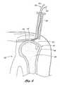
- FIG. 4there is shown a cross-sectional view of a human shoulder 38 on the left side of the body as seen from the front of the body and which illustrates a rotator cuff tendon 40 which is disposed across a humeral head 42.
- This illustrationis intended only to provide a simple structural overview of the physiological elements involved in a typical situation involving the repair of a patient's rotator cuff, where it is to be desired that the rotator cuff tendon 40 be reattached to a humeral head 42.
- the anchoris applicable to many other types of orthopedic repairs which involve the attachment of soft tissue to adjacent bone structure.
- the rotator cuff tendon 40is not attached to the humeral head 42 at the interface 44 between the two, as is typically the case when a patient's rotator cuff has become damaged due to injury or overuse, and requires repair.
- the humeral head 42is comprised of an outer surface of cortical bone 46 and inner cancellous bone 48.
- a trocar 50has been inserted into the shoulder 38 in proximity to the area where the rotator cuff tendon 40 is to be reattached to the humeral head 42, to allow for arthroscopic access, and a hole 52 has been made, preferably by drilling or punching, in the desired location through the cortical bone 46 and into the cancellous bone 48.
- a suture 28,is stitched in a suitable manner to the rotator cuff tendon 40 which is to be secured to the humeral head 42.
- the stitching processmay be accomplished by any known means, and any known suture stitch may be employed, the objective being to ensure a secure stitch so that the suture is not inadvertently separated from the tendon after completion of the repair procedure, necessitating re-entry to the surgical site.
- the sutureis attached to the soft tissue using a "mattress stitch", which is well known in the art as being a particularly secure stitch which is unlikely to fail postoperatively.
- a suturing instrumentis inserted into the trocar to perform the aforementioned suturing step.
- a preferred suturing approachis taught in co-pending application Serial No. 09/668,055 , entitled Linear Suturing Apparatus And Methods, filed on September 21, 2000.
- inventive devicesmay also be utilized in an open surgical procedure, if desired, wherein the sutures are manually placed. Once the suturing process is completed, the free ends 33 of the suture 28 are removed proximally through the trocar from the patient's body, together with the suturing instrument.
- the free ends 33 of the suture 28, while still outside of the patient's body,are then passed distally through the toggle ring member 14 and the casing 19, into the body 12, around the suture return pin 30, and then proximally out of the body 12 and casing 19 where the free ends 33 may be manipulated by the surgeon.
- the anchor apparatus 10is still in its undeployed state.
- the mandrel 34has been inserted over the casing 19 such that it is disposed adjacent to the proximal end of the toggle ring member 14 prior to deployment.
- Fig. 6illustrates how the bone anchor is deployed after it has been inserted into the hole 52 in the humeral head 42.
- the entire apparatusis inserted into the hole 52 a sufficient distance so that the toggle ring member 14 is disposed just distally of the juncture between the cortical bone 46 and the cancellous bone 48, just within the cancellous bone 48.
- the bone anchor 10may be deployed within the cancellous bone 48 to lock the anchor 10 into position, thereby securely attaching the suture 28 to the humeral head 42.
- the casing 19is withdrawn proximally.
- this withdrawal force applied to the casing 19will also cause the body 12 to move in a proximal direction until it engages the distal side of the toggle ring member 14.
- the mandrel 34is maintained in a stationary position, so that the continued proximal movement of the body 12 against the toggle ring member 14 results in the application of sufficient force on the struts 16 to cause them to deform, thereby decreasing the axial spacing between the toggle ring member 14 and the proximal end of the body 12 to a relatively small distance.
- this force applied against the toggle ring member 14 and struts 16also cause the toggle ring member 14 to move in a pivoting fashion from an undeployed orientation, wherein the ring member 14 is disposed at an acute angle ⁇ relative to the longitudinal axis 15 ( Fig. 2a ) to present a smaller profile in a direction transverse to the axis 15, to a deployed orientation, wherein the ring member 14 is disposed substantially transversely to the axis 15 ( Fig. 2b ) in order to present a larger profile in a direction transverse to the axis 15.
- the mandrel 34it is preferable to maintain the mandrel 34 in a stationary position, while moving the body 12 proximally to apply deployment force against the toggle ring member 14.
- the reason for thisis that by holding the mandrel 34 steady, the practitioner can accurately control the depth at which the anchor 10 is deployed, so that the toggle ring member is deployed just distally of the distal surface of the cortical bone 46. If, instead, the mandrel were moved distally to apply force against the toggle ring member 14, ascertainment of the depth of the deployed toggle ring member would be more difficult.
- the mandrel 34may be moved distally against the toggle ring member 14 while the casing 19 is maintained in a stationary position, thereby pushing the toggle ring member 14 distally until the resultant forces on the struts 16 cause them to deform. Still another alternative is to move the mandrel 34 distally, while at the same time moving the body 12 proximally, to apply both a proximally directed and a distally directed force against the toggle ring member 14 and associated struts 16.
- FIG. 6the manner in which the casing 19 and mandrel 34 are removed from the procedural site after deployment of the bone anchor 10 is illustrated.
- the toggle ring member 14is firmly positioned in the cancellous bone 48 just below the cortical bone surface 46
- the casing 19is withdrawn in a proximal direction.
- the tongue 20which is inserted through the slot 22 in the distal end 26 of the casing 19 is designed to break upon the application of a withdrawal force of a predetermined strength on the casing 19, which force is considerably less than the force necessary to pull the deployed bone anchor 10 out of the hole 52.
- the bone anchor 10remains firmly in place while the casing 19 and the mandrel 34 are removed through the trocar and out of the body.
- Fig. 7provides an overall view of the shoulder area and the bone anchor apparatus after the bone anchor 10 has been deployed into the hole 52 in the humeral head 42 and as the casing 19 and mandrel 34 are being removed through the trocar 50.
- the free ends 33 of the suture 28still extend through the trocar 50 and out of the body. The surgeon may then cinch and knot the free ends of the suture 28 to secure the suture 28 to the bone anchor 10, and to snug the tendon 40 to the humeral head 42, as desired, or may employ a separate suture-securing device.
- FIG. 8illustrates an alternative embodiment of the present invention.
- a bone anchor 110is shown which is similar to the bone anchor described in connection with the above illustrations. It comprises a tubular or cylindrical body 112 and a toggle ring member 114.
- the only significant difference in this alternative embodimentis the absence of the thin struts 16 shown in the prior figures.
- the toggle ring member 114is hinged directly to the anchor body 112. It is deployed in the same manner using a casing and a mandrel as described above, but in this embodiment the toggle ring member 114 simply bends at the hinge point 116 to move from its undeployed position (illustrated in Fig. 8 ) in relation to the anchor body 110 to its deployed position (not shown, but similar to the deployed position of the first embodiment illustrated in Fig. 2b ).
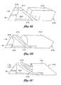
- Fig. 9ashows an embodiment consisting of a substantially rectangular anchor 210 having a solid anchor body 212 and a solid rectangular member 214 attached by means of a hinge 216 for deployment into the bone structure below the cortical surface.
- the rectangular member 214is deployed by means of a mandrel 218 which pushes a first end of the rectangular member 214 distally at the same time that a rod 220 attached to the opposing end of the rectangular member 214 pulls that end proximally, thereby deploying the member 214 to an orientation having a greater transverse profile, as in the prior embodiments.
- the rod 220is designed such that it will break away from the rectangular member 214 when a proximal force is exerted on it after deployment of the rectangular member 214 so that the rod 220 and the mandrel may be removed.
- Fig. 9bThe alternative embodiment shown in Fig. 9b is deployed in exactly the same manner as the embodiment shown in Fig. 9a .
- the only difference between the two embodimentsis the configuration of the anchor 310, which has a tubular body 312 and a tubular toggle ring deployment member 314.
- Fig. 9cshows yet another alternative embodiment of a bone anchor 410 with a hollow tubular body 412, and a hollow toggle ring deployment member 414 similar to the embodiment described above, supra, but which is deployed by means of a mandrel 418 and rod 420 as with the alternative embodiments described in connection with Figs. 9a and 9b .
- FIGs. 10A through 20Bare illustrated a preferred embodiment which includes a presently preferred suture anchoring approach.
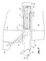
- FIGs. 10A-10B and 11A-11Dare cross-sectional views through the left shoulder of a human as viewed from the front and illustrate the use of an exemplary suture anchor system 520 for repairing a rotator cuff tendon injury.
- the rotator cuff tendon 522is shown in its natural positioned overlying the bulbous humeral head 524 of the humerus bone 526. In rotator cuff injuries, the tendon 522 partially or completely separates from its attachment point to the humeral head 524, which point of attachment is typically located along an angled shelf, the greater tuberosity 528.
- the surgeonthreads one or more sutures through the rotator cuff tendon 522 and anchors them to the greater tuberosity 528.
- the suture anchor system 520 of the present inventionfacilitates this latter step of anchoring the sutures to the greater tuberosity 528.
- a generally tubular trocar 530provides a conduit through the soft tissue of the shoulder for the suture anchor system 520 of the present invention.
- the surgeonmakes an incision or stab wound through the outer dermal layers of sufficient size to permit passage of the trocar 530 through skin and the deltoid muscle into proximity with the humeral head 524.
- Various trocars and techniques for creating the approach passagewayare known and may be utilized with the present invention.
- more than one incision and conduitmay be necessary to perform the several suturing and anchoring steps.
- the surgeonAfter establishing one or more direct conduits to the humeral head 524, the surgeon passes a length of suture through the soft tissue of the rotator cuff tendon 522 so that a loop 532 of suture material is embedded therein, as seen in Fig. 10B .
- the two free ends 534a, 534b of the length of sutureare withdrawn from the patient and coupled to the suture anchor system 520. The specifics of this coupling and subsequent manipulation of the two free ends of the suture will be described more fully below.
- the two free ends 534a, 534bpass into a lumen at the distal end of the suture anchor system 520 and extend through the lumen in a proximal direction to a proximal end of the system to enable fixation or pulling of the suture ends.
- the two free ends 534a, 534bare shown projecting from a proximal end of the system.
- the system 520further includes a plurality of concentrically disposed cannulas or tubes as shown that perform the knotless suture anchoring operation. The interrelationship and functioning of these tubes will also be more fully explained below.
- the exemplary system 520 as illustratedis particularly suitable for anchoring a suture to a body cavity, specifically the humeral head 524 as shown.
- a conventional techniqueis to first form a blind hole or cavity 540 through the cortical layer 542 and into the soft cancellous matter 544, as seen in Figs. 10A-10B and 11A-11D . The surgeon then positions a suture anchor 546 within the cavity 540 and deploys it such that it cannot be removed from the cavity.
- the suture anchor 546performs two functions: anchoring itself within the body cavity and anchoring the sutures therein.
- the former functionis accomplished using an expandable anchoring structure 548 located on the proximal end of the suture anchor 546.
- the anchoring structure 548is preferably the toggle ring 14 illustrated in Figs. 1-7 , and functions like a toggle bolt used in ceiling fixtures, specifically expanding to a larger dimension in the cavity 540 beyond the hard cortical bone 542. In this manner, the suture anchor 546 is prevented from being removed from the cavity 540 once the anchoring structure 548 is deployed.
- the present inventionillustrates a particular anchoring structure 548, which is similar to the afore-described toggle ring 14, it should be noted that any similar expedient will work.
- a different toggle-like anchoring structuremay be used such as shown in co-pending application Serial Number 09/616,802, filed July 14,2000 , Alternatively, an anchoring structure that expands into contact with the cancellous matter 544 may be used.
- the second function of the suture anchor 546is the anchoring or fixation of the suture with respect to the suture anchor itself, without the use of knots.
- the particular manner of anchoring the suture with respect to the suture anchor 546permits easy adjustment of the length of suture between the suture anchor and the loop 532 formed in the soft tissue. This adjustment allows the surgeon to establish the proper tension in the length of suture for effective repair of the soft tissue; reattachment of the rotator cuff tendon 522 in the illustrated embodiment.
- Fig. 11Dshows the fully deployed suture anchor 546 after the free ends 534a, 534b have been placed in tension and locked within the suture anchor.
- the remaining steps in the procedureinvolve withdrawing the concentric tubes from the surgical site and severing the free ends 534a, 534b close to the suture anchor 546.
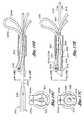
- Figs. 12A-12Care different partial longitudinal sectional views taken through the exemplary suture anchor system 520 of the present invention.
- the suture anchor 546is seen in cross-section disposed in a close-fitting relationship within a delivery tube 550.
- the delivery tube 550may be arranged to slide within a larger tube 552, sometimes known as an introducer tube, that includes a valve (not shown) on a proximal end to prevent fluid leakage therefrom.
- a fluid leakage valvemay be provided on the proximal end of the trocar 530 seen in Figs. 10A-10B .
- the suture anchor 546is defined by a generally tubular anchor body 554 and an inner deployment tube 556 fits closely within a proximal end and is fastened therein.
- the exemplary suture anchor 546is shown and described in greater detail below with respect to Figs. 13A-14 .
- the deployment tube 556can also be seen on the right side in Fig. 12A projecting from the series of concentric tubes, with the free ends 534a, 534b of the length of suture projecting therefrom.
- a die tube 558 sized intermediate the delivery tube 550 and the deployment tube 556is arranged for longitudinal displacement over the deployment tube 556.
- suture anchor 546is undeployed within the delivery tube 550 and the die tube 558 is positioned just proximal to the expandable anchoring structure 548.
- a further component of the suture anchor system 520is a suture locking plug 562 having an actuation rod 564 removably attached to a proximal end thereof and extending proximally within the deployment tube 556.
- Figs. 12A-12Call show the suture loop 532 extending transversely from within the concentric tubes of the suture anchor system 520.
- the delivery tube 550is provided with an axial slot 565
- the deployment tube 556is provided with an axial slot 566
- the die tube 558has an axial slot 567.
- the free ends 534a, 534b of the length of suturepass through these aligned axial slots 565, 566, 567 to the interior of the deployment tube 556 that opens into the lumen 568 of the tubular body 554.
- the aligned axial slots 565, 566, 567permit passage of the free ends 534a, 534b into the system 520 from a location midway along the concentric tubes, as indicated in Figs. 10A-11D .
- the various described components of the suture anchor system 520are relatively axially movable to deploy the suture anchor 546.
- Various meansare known to relatively displace concentric tubes a predetermined distance and/or with a predetermined displacement force.
- the concentric tubesmay extend out of the trocar 530 to an actuation device in the form of concentric syringe bodies/finger tabs.
- the concentric tubesmay be attached to relatively movable parts in a gun-type handle, and actuated by triggers or other such levers. It is to be understood therefore that the present invention is not limited by the particular actuation device on its proximal end, and no further description in this regard will be provided.
- FIGs. 13A-15illustrate one embodiment of a suture anchor 546 isolated from the remainder of the system and having the aforementioned tubular anchor body 554 and deployable anchoring structure 548.
- the anchor body 554defines a lumen 568 therewithin.
- Figs. 13A and 13Balso illustrate the suture locking plug 562 and attached actuation rod 564.
- the anchor body 554has the anchoring structure 548 on its proximal end and a suture pulley or suture return member 570 disposed in proximity to its distal end.
- the aforementioned suture loop 532is schematically illustrated out of the soft tissue for clarity, and it should be understood that this suture loop 532 is embedded in the soft tissue in actual use of the system.
- the free ends 534a, 534b of the length of suturepass through an angled toggle ring 572 of the anchoring structure 548 and into an open proximal end 574 of the lumen 568 formed within the tubular anchor body 554.
- the angled toggle ring 572attaches to the proximal end 574 via a pair of plastically deformable struts 576.
- Both the toggle ring 572 and struts 576are initially formed as a projection of the tubular anchor body 554. After continuing in the distal direction through the lumen of the anchor body 554, the free ends 534a, 534b wrap around the suture return member 570 and traverse the lumen in the proximal direction to emerge from the angled toggle ring 572 as shown.
- the actuation rod 564extends into an open distal mouth 576 of the anchor body 554 and through the lumen 568 and angled toggle ring 572.
- the actuation rod 564 and four strands of the length of suturethus share the space within the lumen 568. Because of the relatively smaller size of the actuation rod 564 with respect to the lumen 568, the length of suture may slide axially within the lumen without interference. It can therefore be seen that because the suture loop 532 is embedded in soft tissue, pulling on the free ends 534, 534b of the length of suture places the suture loop in tension.
- the deployment tube 556can be seen attached within the lumen 568 of the anchor body 554 using a tab 580.
- a tab 580bent inwardly from the anchor body 554 and welded or otherwise secured to the deployment tube 556 is a suitable expedient.
- the tab 580is desirably provided at only one location around the circumferential junction between the deployment tube 556 and lumen 568 to facilitate severing of this connection, although more than one attachment may be provided.
- the tab 580thus secures the deployment tube 556 within the anchor body 554 of the suture anchor 546, while both the die tube 558 and actuation rod 564 can freely slide with respect to the anchor body 554.
- the surgeonadvances the deployment tube 556 having the suture anchor 546 attached thereto into the cavity.
- the suture locking plug 562 and die tube 558advance along with the deployment tube 556, and the resulting configuration is seen in Fig. 10B .
- the surgeoninsures that the suture anchor 546, and in particular the anchoring structure 548, has been inserted past the hard outer layer of cortical bone 542.
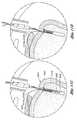
- the anchoring structureis then expanded as seen in Fig. 11A .
- the die tube 558contacts the angled toggle ring 572 and forces it into an orientation that is generally perpendicular with respect to the axis of the suture anchor 546.
- the die tube 558is desirably held stationary while the deployment tube 556 having the suture anchor 546 attached thereto is pulled in a proximal direction.
- the relative movement of these tubescan be accomplished using a handle or other device exterior to the patient's body. Pulling on the deployment tube 556 forces one side of the angled toggle ring 572 against the generally circular distal mouth of the deployment tube 556 which deforms the struts 576 as the toggle ring 572 moves into a perpendicular orientation.
- the deployment tube 556After the anchoring structure 548 is deployed, further pulling on the deployment tube 556 detaches it from the suture anchor 546. Specifically, the aforementioned welded tab 580 severs at a predetermined pulling force. The die tube 558 remains in place in its fixed position, and provides a reaction force against the suture anchor 546. The deployment tube 556 is then pulled free and retracted out of the way, as indicated in Fig. 11B . At this stage, the suture anchor 546 is secured with respect to the body cavity, but the length of suture passing therethrough remains free to be axially displaced.
- the suture loop 532is seen projecting upward from the system, but it again should be noted that this loop is embedded in soft tissue in use of the system.
- the two free ends 534a, 534bextend through an axial slot 590 in the delivery tube 550, and through an axial slot 590 in the deployment tube 556 into lumen 568 of the suture can 546. As best seen in Fig. 12C , the free ends pass through the lumen 568 and around the aforementioned suture return member 570.
- the free endsthen travel in a proximal direction through the lumen 568 and through the lumen of the deployment tube 556 to emerge from proximal end of the system. Because the suture loop 532 is embedded in soft tissue, pulling on both of the free ends 534a, 534b, or pulling on one end while holding one fixed, will create tension in the length of suture.
- the suture return member 570provides relatively little resistance to sliding of the length of suture therearound, and thus this tensioning can be accomplished relatively easily.
- the suture return member 570comprises a pin oriented transversely to the axis of the suture anchor 546 and located along a sidewall thereof. As seen best in Fig. 13A , the pin may span an axial slot 600 in a sidewall of the anchor body 554 so that the free ends 534a, 534b of length of suture can pass out through the slot and around the pin. Alternatively, two axially spaced holes with chamfered or rounded edges may be formed in the sidewall of the anchor body 554 through which the free ends 534a, 534b can be threaded and fixed. Of course, numerous structures are contemplated that provide the function of the illustrated pin-type suture return member 570.
- the suture return member 570can be arranged to swivel or otherwise move to facilitate sliding motion of the free ends 534a, 534b therearound.
- the pin-type suture return member 570can be formed separately from the anchor body 554 and inserted within a pair of facing holes in the edges of the slot 600. In this manner, the pin-type suture return member 570 rotates within the holes, thus reducing friction between the free ends 534a, 534b and the suture return member.
- the step of tensioning the length of sutureis seen in Fig. 11C , wherein the suture locking plug 562 remains in its initial position spaced from the anchor body 554. Adjustment of the length of the suture between the suture anchor 546 and the loop 532 is very important to ensure proper fixation of the rotator cuff tendon 522 with respect to the humeral head 524. If the suture is pulled too tightly, the rotator cuff tendon 522 may be unduly stressed, and the loop 532 may even pulled free from the tendon. On the other hand, if the suture is too loose, the goal of reattaching the tendon 522 in its proper location will be compromised.
- the sutureis anchored with suspect to the anchor body 554. This is done by displacing the suture locking plug 562 in a proximal direction so that it is forced into the lumen 568.
- the plug 562includes a generally cylindrical shaft 602 with a bullet-shaped proximal nose 604 to help prevent its catching on a distal mouth 605 of the anchor body 54. Proximal displacement of the actuation rod 564 from outside the body causes proximal movement of the attached plug 562.
- Figs. 16A-17Cshow the anchor body 554 without the aforementioned anchoring structure 548, for clarity. These views illustrate the movement of the suture locking plug 562 into the lumen 566, and consequent locking of the length of suture therein.
- the diameter of the cylindrical shaft 602 of the plug 562is sized to be slightly smaller than the inner diameter of the lumen 568. As seen in Figs. 17B and 17C , the diameter of the cylindrical shaft 602 is such that it compresses the four strands of the length of suture against the lumen 568.
- the locking plug 562is dimensioned to compress or "crush" the length of suture in the lumen 568 and interfere with its axial movement therethrough.
- the amount of compressionmay be measured by the amount of pull force on the suture necessary to move it once the plug is in position. Desirably, the pull force is in a range that would exceed the USP (United States Pharmacopeia) Standard knot pull strength (USP 24) of the suture used. In the specific case of #2 braided polyester suture, this knot pull strength is approximately 3.5 Kgf. In practice, however, the knot pull strength of commercially available #2 braided polyester sutures approaches 14 Kgf.
- Proximal displacement of the locking plug 562 within the anchor body 554is desirably limited by a positive stop.
- a stop flange 610projects outwardly from the cylindrical shaft 602 at its distal end.
- the stop flange 610slides within an axial slot 612 at the distal end of the anchor body 554 that terminates at a slot end 614.
- proximal movement of the locking plug 562is ultimately restricted by contact between the stop flange 610 and the slot end 614.
- other configurations that provide a positive stop to proximal movement of the locking plug 562are contemplated.
- a stop surfacemay project inwardly from the lumen 568 to interfere with movement of the plug 562.
- One advantage provided by the present inventionis the ability to tighten a suture loop embedded within soft tissue to a predetermined tension, and then locked to the suture within a suture anchor without even slightly altering that tension.
- the locking plug 562is shown partly inserted within the tubular body 554 during the step of being pulled proximal by the actuation rod 564 as indicated by the movement arrows 616.
- the free ends 534a, 534b of the length of sutureextend around the suture return member 570, having previously been tensioned to a predetermined amount.
- Proximal movement of the locking plug 562acts on all four strands of the length of suture within the lumen of the tubular body 554, and thus imparts equal frictional forces to all of the strands tending to urge them in a proximal direction. Because the four strands loop around the suture return member 570, with two coming and two going, these frictional forces cancel out such that the free ends 534a, 534b do not migrate within the tubular body 554. Because the suture return member 570 and tubular body 554 remain fixed with respect to the suture loop 532 (which is embedded within the soft tissue), the predetermined tension within the loop remains constant during the suture locking step.
- deformation of the angled toggle ring 572forces it into an oval shape at the proximal end 574 of the anchor body 554.
- This oval shapemay have a minor dimension that is smaller than the diameter of the cylindrical shaft 602, or more typically the struts 576 may be bent into the path of the shaft 602, thus presenting an interference and a positive stop to the shaft movement.
- the actuation rod 564may be bent back upon the exterior surface of the locking plug 562 to form the stop surface.
- the actuation rod 564may be detached therefrom.
- the actuation rod 564extends within a through bore in the cylindrical shaft 602 and includes a frangible point 620 in that bore.
- the segment of the actuation rod distal to this frangible point 620is secured within the bore in a conventional manner, such as with crimping indicated at 622 in Fig. 16A .
- the die tube 558may be used as a reaction force against the anchor body 554 while the actuation rod 564 is pulled in the proximal direction, causing the frangible point 620 to fracture.
- the final configurationis seen in Fig. 11D .
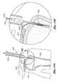
- Fig. 19shows an alternative surgical technique for using a combined suture anchor 546' and anchoring structure 548' to repair a rotator cuff tendon 522.
- the surgeonrather than forming a blind cavity within the humeral head 524, the surgeon forms a cavity 630 that transects the greater tuberosity 528 and opens through the cortical layer 542 at both ends. After embedding the loop 532 of suture material within the rotator cuff tendon 522, the free ends 534a, 534b are inserted into and threaded through the cavity 630.
- the ends 534a, 534bare then passed through the lumen formed within the combined suture anchor 546' and anchoring structure 548', which combination is then inserted as shown into the cavity 630.
- the free ends 534a, 534b of sutureare then tightened to the prescribed level and secured within the suture anchor 546'.
- the combined suture anchor 546' and anchoring structure 548'may be configured somewhat differently to permit the aforementioned tightening step, though the suture locking steps are preferably accomplished in the same manner as described above; namely, with a suture locking plug compressing the length of suture within the suture anchor 546'.
- the anchoring structure 548'contacts the exterior of the cortical bone rather than the interior as described above.
- FIGs. 20A and 20Billustrate an alternative suture anchor 640 of the present invention having a body cavity anchoring structure 642 on a proximal end.
- a length of sutureis shown having a loop 644 and a pair of free ends 646a, 646b passing through the anchoring structure 642 and through a lumen 648 of a generally tubular body 650 of the suture anchor 640.
- the free ends 646a, 646bpass out of the lumen 648 through a first aperture 652a and re-enter the lumen through a second aperture 652b located distally from the first aperture.
- the lumen 648 in the region of the apertures 652a, 652bis only partly defined by a semi-cylindrical extension of the tubular body 650, but other arrangements having a more complete lumen at this location are within the scope of the present invention.
Landscapes
- Health & Medical Sciences (AREA)
- Surgery (AREA)
- Life Sciences & Earth Sciences (AREA)
- Medical Informatics (AREA)
- Animal Behavior & Ethology (AREA)
- Engineering & Computer Science (AREA)
- Biomedical Technology (AREA)
- Heart & Thoracic Surgery (AREA)
- Rheumatology (AREA)
- Molecular Biology (AREA)
- Nuclear Medicine, Radiotherapy & Molecular Imaging (AREA)
- General Health & Medical Sciences (AREA)
- Public Health (AREA)
- Veterinary Medicine (AREA)
- Surgical Instruments (AREA)
- Braiding, Manufacturing Of Bobbin-Net Or Lace, And Manufacturing Of Nets By Knotting (AREA)
- Ropes Or Cables (AREA)
- Prostheses (AREA)
Abstract
Description
- This invention relates generally to apparatus for attaching soft tissue to bone, and more particularly to anchors and methods for securing connective tissue, such as ligaments or tendons, to bone. The invention has particular application to arthroscopic surgical techniques for reattaching the rotator cuff to the humeral head, in order to repair the rotator cuff.
- It is an increasingly common problem for tendons and other soft, connective tissues to tear or to detach from associated bone. One such type of tear or detachment is a "rotator cuff' tear, wherein the supraspinatus tendon separates from the humerus, causing pain and loss of ability to elevate and externally rotate the arm. Complete separation can occur if the shoulder is subjected to gross trauma, but typically, the tear begins as a small lesion, especially in older patients.
- To repair a torn rotator cuff, the typical course today is to do so surgically, through a large incision. This approach is presently taken in almost 99% of rotator cuff repair cases. There are two types of open surgical approaches for repair of the rotator cuff, one known as the "classic open" and the other as the "mini-open". The classic open approach requires a large incision and complete detachment of the deltoid muscle from the acromion to facilitate exposure. The cuff is debrided to ensure suture attachment to viable tissue and to create a reasonable edge approximation. In addition, the humeral head is abraded or notched at the proposed soft tissue to bone reattachment point, as healing is enhanced on a raw bone surface. A series of small diameter holes, referred to as "transosseous tunnels", are "punched" through the bone laterally from the abraded or notched surface to a point on the outside surface of the greater tuberosity, commonly a distance of 2 to 3 cm. Finally, the cuff is sutured and secured to the bone by pulling the suture ends through the transosseous tunnels and tying them together using the bone between two successive tunnels as a bridge, after which the deltoid muscle must be surgically reattached to the acromion. Because of this maneuver, the deltoid requires postoperative protection, thus retarding rehabilitation and possibly resulting in residual weakness. Complete rehabilitation takes approximately 9 to 12 months.
- The mini-open technique, which represents the current growing trend and the majority of all surgical repair procedures, differs from the classic approach by gaining access through a smaller incision and splitting rather than detaching the deltoid. Additionally, this procedure is typically performed in conjunction with arthroscopic acromial decompression. Once the deltoid is split, it is retracted to expose the rotator cuff tear. As before, the cuff is debrided, the humeral head is abraded, and the so-called "transosseous tunnels", are "punched" through the bone or suture anchors are inserted. Following the suturing of the rotator cuff to the humeral head, the split deltoid is surgically repaired.
- Although the above described surgical techniques are the current standard of care for rotator cuff repair, they are associated with a great deal of patient discomfort and a lengthy recovery time, ranging from at least four months to one year or more. It is the above described manipulation of the deltoid muscle together with the large skin incision that causes the majority of patient discomfort and an increased recovery time.
- Less invasive arthroscopic techniques are beginning to be developed in an effort to address the shortcomings of open surgical repair. Working through small trocar portals that minimize disruption of the deltoid muscle, a few surgeons have been able to reattach the rotator cuff using various bone anchor and suture configurations. The rotator cuff is sutured intracorporeally and an anchor is driven into bone at a location appropriate for repair. Rather than thread the suture through transosseous tunnels which are difficult or impossible to create arthroscopically using current techniques, the repair is completed by tying the cuff down against bone using the anchor and suture. Early results of less invasive techniques are encouraging, with a substantial reduction in both patient recovery time and discomfort.
- Unfortunately, the skill level required to facilitate an entirely arthroscopic repair of the rotator cuff is inordinately high. Intracorporeal suturing is clumsy and time consuming, and only the simplest stitch patterns can be utilized. Extracorporeal knot tying is somewhat less difficult, but the tightness of the knots is difficult to judge, and the tension cannot later be adjusted. Also, because of the use of bone anchors to provide a suture fixation point in the bone, the knots that secure the soft tissues to the anchor by necessity leave the knot bundle on top of the soft tissues. In the case of rotator cuff repair, this means that the knot bundle is left in the shoulder capsule where it can be felt by the patient postoperatively when the patient exercises the shoulder joint. So, knots tied arthroscopically are difficult to achieve, impossible to adjust, and are located in less than optimal areas of the shoulder. Suture tension is also impossible to measure and adjust once the knot has been fixed. Consequently, because of the technical difficulty of the procedure, presently less than 1% of all rotator cuff procedures is of the arthroscopic type, and is considered investigational in nature.
- Another significant difficulty with current arthroscopic rotator cuff repair techniques is shortcomings related to currently available suture anchors. Suture eyelets in bone anchors available today, which like the eye of a needle are threaded with the thread or suture, are small in radius, and can cause the suture to fail at the eyelet when the anchor is placed under high tensile loads.
- There are various bone anchor designs available for use by an orthopedic surgeon for attachment of soft tissues to bone. The basic commonality between the designs is that they create an attachment point in the bone for a suture that may then be passed through the soft tissues and tied, thereby immobilizing the soft tissue. This attachment point may be accomplished by different means. Screws are known for creating such attachments, but existing designs suffer from a number of disadvantages, including their tendency to loosen over time, requiring a second procedure to later remove them, and their requirement for a relatively flat attachment geometry.
- Another approach is to utilize the difference in density in the cortical bone (the tough, dense outer layer of bone) and the cancellous bone (the less dense, airy and somewhat vascular interior of the bone). There is a clear demarcation between the cortical bone and cancellous bone, where the cortical bone presents a kind of hard shell over the less dense cancellous bone. The aspect ratio of the anchor is such that it typically has a longer axis and a shorter axis and usually is pre-threaded with a suture. These designs use a hole in the cortical bone through which an anchor is inserted. The hole is drilled such that the shorter axis of the anchor will fit through the diameter of the hole, with the longer axis of the anchor being parallel to the axis of the drilled hole. After deployment in to the cancellous bone, the anchor is rotated 90B so that the long axis is aligned perpendicularly to the axis of the hole. The suture is pulled, and the anchor is seated up against the inside surface of the cortical layer of bone. Due to the mismatch in the dimensions of the long axis of the anchor and the hole diameter, the anchor cannot be retracted proximally from the hole, thus providing resistance to pull-out. These anchors still suffer from the aforementioned problem of eyelet design that stresses the sutures.
- Still other prior art approaches have attempted to use a "pop rivet" approach. This type of design requires a hole in the cortical bone into which a split shaft is inserted. The split shaft is hollow, and has a tapered plug leading into its inner lumen. The tapered plug is extended out through the top of the shaft, and when the plug is retracted into the inner lumen, the tapered portion causes the split shaft to be flared outwardly, ostensibly locking the device into the bone.
- Other methods of securing soft tissue to bone are known in the prior art, but are not presently considered to be feasible for shoulder repair procedures, because of physicians' reluctance to leave anything but a suture in the capsule area of the shoulder. The reason for this is that staples, tacks, and the like could possibly fall out and cause injury during movement. As a result of this constraint, the attachment point often must be located at a less than ideal position. Also, the tacks or staples require a substantial hole in the soft tissue, and make it difficult for the surgeon to precisely locate the soft tissue relative to the bone.
- As previously discussed, any of the anchor points for sutures mentioned above require that a length of suture be passed through an eyelet fashioned in the anchor and then looped through the soft tissues and tied down to complete the securement. Much skill is required, however, to both place the sutures in the soft tissues, and to tie knots while working through a trocar under endoscopic visualization.
- There have been attempts to solve some of the problems that exist in current anchor designs. One such approach is disclosed in
U.S. Patent No. 5,324,308 to Pierce . In this patent, there is disclosed a suture anchor that incorporates a proximal and distal wedge component having inclined mating faces. The distal wedge component has two suture thread holes at its base through which a length of suture may be threaded. The assembly may be placed in a drilled hole in the bone, and when tension is placed on the suture, the distal wedge block is caused to ride up against the proximal wedge block, expanding the projected area within the drilled hole, and locking the anchor into the bone. This approach is a useful method for creating an anchor point for the suture, but does not in any way address the problem of tying knots in the suture to fix the soft tissue to the bone. - The problem of placing sutures in soft tissues and tying knots in an endoscopic environment is well known, and there have been attempts to address the problem and to simplify the process of suture fixation. One such approach is disclosed in
U.S. Patent No. 5,383,905 to Golds et al . The patent describes a device for securing a suture loop about bodily tissue that includes a bead member having a longitudinal bore and an anchor member adapted to be slidably inserted within the bore of the bead member. The anchor member includes at least two axial compressible sections which define a passageway to receive two end portions of a suture loop. The axial sections collapse radially inwardly upon insertion of the anchor member within the bore of the bead member to securely wedge the suture end portions received within the passageway. - Although the Golds et al. patent approach utilizes a wedge-shaped member to lock the sutures in place, the suture legs are passing through the bore of the bead only one time, in a proximal to distal direction, and are locked by the collapsing of the wedge, which creates an interference on the longitudinal bore of the anchor member. Also, no provision is made in this design for attachment of sutures to bone. The design is primarily suited for locking a suture loop, such as is used for ligation or approximation of soft tissues.
- A prior art approach that includes tissue attachment is described in
U.S. Patent No. 5,405,359 to Pierce . In this system, a toggle wedge is comprised of a two piece structure comprising a top portion characterized by the presence of a barbed tip and a bottom portion. The suturing material extends through apertures in each of the two toggle portions, and is maintained in position by means of a knot disposed in the suture at a lower edge of the bottom toggle portion. To anchor the suture into adjacent soft tissue, the two toggle portions are rotated relative to one another, as shown for example in Fig. 33. The disclosure states that the device could be used to anchor suture in bone, as well as soft tissue, if two embodiments are utilized in tandem. However, the system is disadvantageous in that it is complex, difficult to manipulate, and still requires the tying of a knot in the suture. - Another approach that includes bone attachment is described in
U. S. Patent No. 5,584,835 to Greenfield . In this patent, a two part device for attaching soft tissue to bone is shown. A bone anchor portion is screwed into a hole in the bone, and is disposed to accept a plug that has been adapted to receive sutures. In one embodiment, the suture plug is configured so that when it is forced into its receptacle in the bone anchor portion, sutures that have been passed through an eyelet in the plug are trapped by friction between the wall of the anchor portion and the body of the plug portion. - Although there is some merit to this approach for eliminating the need for knots in the attachment of sutures to bone, a problem with being able to properly set the tension in the sutures exists. The user is required to pull on the sutures until appropriate tension is achieved, and then to set the plug portion into the bone anchor portion. This action increases the tension in the sutures, and may garrot the soft tissues or increase the tension in the sutures beyond the tensile strength of the material, breaking the sutures. In addition, the minimal surface area provided by this anchor design for pinching or locking the sutures in place will abrade or damage the suture such that the suture's ability to resist load will be greatly compromised.
- A disclosure that incorporates bone attachment and eliminates knot tying is set forth in
U.S. Patent No. 5,702,397 to Goble et al. One embodiment, in particular, is shown in Fig. 23 of that patent and includes a bone anchor that has a threaded body with an inner cavity. The cavity is open to one end of the threaded body, and joins two lumens that run out to the other end of the threaded body. Within the cavity is disposed a gear, journaled on an axle. A length of suture is threaded through one lumen, around the gear, and out through the other lumen. A ball is disposed within the cavity to ride against a tapered race and ostensibly lock the suture in place. What is not clear from the patent disclosure is how the force D shown as the tension in the suture would lock the ball into the race. Although this embodiment purports to be a self-locking anchor adapted for use in blind holes for fixing sutures into bone, the construct shown is complicated, and does not appear to be adequate to reliably fixate the suture. U.S. Patent No. 5,782,863 to Bartlett discloses a suture anchor including bone attachment, which simply comprises a conical suture anchor having an anchor bore through which a length of suture is threaded. The anchor is inserted into a bore within a portion of bone using an insertion tool having a shape memory insertion end. As the anchor is inserted, because of its conical shape, it will re-orient itself by rotating in order to fit into the bore, bending the end of the insertion tool. However, once the proximal edge of the bone anchor enters cancellous bone, the shape memory insertion end of the insertion tool will begin resuming its natural straight orientation, thus rotating the anchor back into its original orientation. The corners of the conical body thus protrude into the soft cancellous bone, and the anchor body is prevented from exiting proximally from the bone bore through the hard cortical bone. The insertion tool is then removed.- The Bartlett patent approach, while innovative, is disadvantageous to the extent that it involves the use of a unique and complex insertion tool, and can be difficult to deploy. It also does not permit suturing of the soft tissue prior to anchoring the suture to bone, and thus does not permit tensioning of the suture to approximate the soft tissue to bone, as desired, at the conclusion of the suturing procedure. Additionally, in preferred embodiments, the suture is knotted to the anchor, a known disadvantage.
- Yet another prior art approach is disclosed in
U.S. Patent No. 5,961,538 to Pedlick et al . In this patent, a wedge shaped suture anchor system is described for anchoring a length of suture within a bore in a bone portion, which comprises an anchor body having an offset suture opening for receiving the length of suture therethrough, and for creating an imbalance in the rotation of the device as it is inserted. A shaft portion is utilized to insert the wedge-shaped anchor body into the bone bore. Once the anchor body is in cancellous bone, below the cortical bone layer, the shaft is pulled proximally to cause the anchor body to rotate, thereby engaging the corners of the anchor body with the cancellous bone. The shaft then becomes separated from the anchor body, leaving the anchor body in place within the bone. - The Pedlick et al. approach is conventional, in that the suture is attached to desired soft tissue after it is anchored within the bone. Consequently, there is no opportunity to tension the suture, as desired, to optimally approximate the soft tissue to the bone upon completion of the surgical procedure. Additionally, the approach is complex and limited in flexibility, since the suture is directly engaged with the bone anchoring body. There is also the possibility that the bone anchoring body will not sufficiently rotate to firmly become engaged with the cancellous bone before the insertion tool breaks away from the anchor body, in which case it will be impossible to properly anchor the suture.
U.S. Patent No. 6,056,773 to Bonutti discloses a suture anchoring system which is somewhat similar to that disclosed by Pedlick et al. A cylindrical suture anchor body is provided which is insertable into a bone bore, using a pusher member which pushes distally on the anchor body from a proximal direction. As the anchor body proceeds into the bone bore, below the cortical bone surface, the suture extending through the lumen of the anchor body applies a proximal tensile force on the anchor body, to cause the anchor body to rotate relative to the pusher member, thereby anchoring the anchor body in cancellous bone. Of course, this system has similar disadvantages to those of the Pedlick et al. system, and requires the suture to be directly engaged with the bone anchoring body.Wo-A99/53844 - What is needed, therefore, is a new approach for repairing the rotator cuff or fixing other soft tissues to bone, wherein both the bone and suture anchors reside completely below the cortical bone surface, there is no requirement for the surgeon to tie a knot to attach the suture to the bone anchor, and wherein suture tension can be adjusted and possibly measured. The procedure associated with the new approach should better for the patient than existing procedures, should save time, be uncomplicated to use, and be easily taught to practitioners having skill in the art.
- According to the present invention, there is provided knotless suture anchor apparatus as set out in
claim 1. The present invention solves the problems outlined above by providing innovative bone anchor and connective techniques which permit a suture attachment which lies entirely beneath the cortical bone surface, and which further permit the attachment of suture to the bone anchor without the necessity for tying knots, which is particularly arduous and technically demanding in the case of arthroscopic procedures. - In operation, when it is desired to deploy the bone anchor, the toggle member is movable, in a pivoting or rotational fashion, between an undeployed position wherein the toggle member has a smaller profile in a direction transverse to the longitudinal axis, which is no wider than the transverse dimension or width of the body member and the hole into which the bone anchor device is disposed, and a deployed position wherein the toggle member has a larger profile in the direction transverse to the axis, which is substantially larger than the width of the hole, so that the outer edges of the toggle member become embedded in the cancellous bone which lies beneath the cortical bone surface, and so that there is no reasonable way, short of widening the hole through the cortical bone, of withdrawing the anchor proximally out of the hole.
- When the toggle member is deployed, the connecting portion may deform such that the axial space is reduced in length. , The connecting portion preferably comprises a one or more struts having proximal ends j joined to the toggle member and distal ends joined to the body member. In manufacture, the body member, struts, and toggle member, which is preferably annular and elliptical in configuration, may all be fabricated from a single piece, such as a hypotube.
- Preferably, the inventive toggle member is disposed at an acute angle relative to the axis in the undeployed position, and is disposed in a substantially transverse orientation relative to the axis in the deployed position.
- The inventors have discovered that, due to potential cyclic loading effects during usage of the affected body part after completion of the medical procedure, it is advantageous to form at least the connecting portion, and preferably the toggle member as well of a biocompatible relatively ductile material. In a presently preferred embodiment, the material comprises an annealed metal, such as stainless steel.
- In a preferred embodiment, there is disposed a mandrel proximally of the toggle member, and a casing extending through the toggle member. The mandrel, together with the body, is useful in actuating the toggle member from its undeployed position to its deployed position.
- In another aspect of the invention, there is provided a bone anchor device for attaching soft tissue to bone, which device has a longitudinal axis and comprises a toggle member being rotatable from an undeployed position wherein the toggle member has a smaller profile in a direction transverse to the axis and a deployed position wherein the toggle member has a larger profile in the direction transverse to the axis. The toggle member has no structure for attaching suture material thereto, since the suture material is to be attached to a body member disposed distally of the toggle member.
- In yet another aspect of the invention, there is provided an apparatus for attaching connective tissue to bone, which apparatus has a longitudinal axis and comprises an annular toggle member and a body member disposed distally of the toggle member, such that there is an axial space between the toggle member and the body member. Advantageously, the toggle member is movable between an undeployed position wherein the toggle member has a smaller profile in a direction transverse to the axis and a deployed position wherein the toggle member has a larger profile in the direction transverse to the axis. When installed in a desired procedural site, in suitable bone, suturing material extends axially through a center aperture in the annular toggle member, without being secured to or contacting the toggle member.
- In still another aspect of the invention, there is provided an apparatus for attaching connective tissue to bone, which apparatus has a longitudinal axis and comprises a toggle member and a body member disposed distally of the toggle member, such that there is an axial space between the toggle member and the body member. The toggle member is movable between an undeployed position wherein the toggle member has a smaller profile in a direction transverse to the axis and a deployed position wherein the toggle member has a larger profile in the direction transverse to the axis. A connecting portion is disposed in the axial space and joins the toggle member to the body member.
- In another aspect of the invention, there is provided an apparatus for attaching connective tissue to bone, which comprises an anchor body having a longitudinal axis and having an anchoring structure for fixing the anchor body within a body cavity. The anchor body has a proximal end, a distal end, and a lumen opening at the proximal end, and further includes a suture return member disposed therein such that a length of suture may be introduced into the lumen from the proximal end, looped around the suture return member, and passed out of the lumen through the proximal end. A suture locking plug is movable within the lumen from a first position to a second position, and a bone anchoring member is attached to the anchor body, preferably at the proximal end thereof, and is movable between an undeployed position and a deployed position. In preferred embodiments of the invention, the suture return member comprises a shaft or pin which may be either fixed or rotatable. The bone anchoring member preferably comprises a toggle member, which, in the undeployed position has a smaller profile in a direction transverse to the longitudinal axis and in the deployed position has a larger profile in the direction transverse to the axis.
- As noted supra, the toggle member is preferably disposed proximally of the anchor body such that there is an axial space between the toggle member and the anchor body. When the toggle member is moved from the aforementioned undeployed position to the aforementioned deployed position, the axial space is reduced in length. A connecting portion is disposed in the axial space and joins the toggle member to the anchor body. The connecting portion preferably comprises a pair of struts having proximal ends joined to the toggle member and distal ends joined to the anchor body.
- A method is described herein of using suture to secure soft tissue, preferably a tendon, with respect to a body cavity, preferably disposed in a portion of bone. The method comprises the steps of passing a length of suture material through soft tissue so that a loop of suture material is disposed in the soft tissue, resulting in two free ends, and providing an anchor body having an open proximal end and a lumen. A suture return member is disposed in the anchor body. Additional steps include passing the two free ends of the length of suture into the lumen of the anchor body through the open proximal end, and looping them about the suture return member such that the two free ends of the suture extend proximally from the lumen through the open proximal end. The anchor body is fixed with respect to the body cavity, and the loop of suture material is tensioned by pulling on one or both of the two free ends of the length of suture, to approximate the soft tissue with respect to the body cavity as desired. A further step is to fasten the two free ends of the length of suture with respect to the anchor body without knots.
- In preferred approaches, the step of fixing the anchor body with respect to the body cavity comprises forming the body cavity, passing the anchor body into the body cavity, and radially expanding anchoring structure, preferably a deployable toggle member, on the anchor body. The anchoring structure is provided on a proximal end of the anchor body so as to engage the cortical layer of the bone and to prevent proximal removal of the anchor body from the body cavity.
- A method is described herein of securing soft tissue to bone, comprising disposing an anchor body having a longitudinal axis and having a length of suture secured therein within a bore disposed in a portion of bone, and deploying a toggle member attached to a proximal end of the anchor body from an undeployed position wherein the toggle member has a smaller profile in a direction transverse to the axis to a deployed position wherein the toggle member has a larger profile transverse to the axis. The toggle member fixes the anchor body axially relative to the portion of bone. A connecting portion joins the toggle member to the anchor body, and is disposed in an axial space between the toggle member and the anchor body. The aforementioned deploying step includes deforming the connecting portion as the toggle member is moved from the undeployed position to the deployed position.
- In accordance with one aspect of the present invention, a knotless suture anchor apparatus for anchoring a length of suture with respect to a body cavity comprises an anchor body having an anchoring structure for fixing the anchor body within a body cavity, and a suture locking plug. The anchor body has proximal and distal ends, and a lumen opening at the proximal end. A suture return member fixed with respect to the anchor body is provided such that a length of suture may be introduced into the lumen from the proximal end, looped around the suture return member, and passed out of lumen through the proximal end. The suture locking plug is movable within the lumen from a first position to a second position. Desirably, the suture locking plug and lumen cooperate such that the suture locking plug does not interfere with axial movement of the length of suture in the first position and interferes with axial movement of the length of suture in the second position, preferably by compressing the length of suture against the anchor body.
- In a preferred embodiment, the anchor body is generally tubular and the lumen opens at the distal end as well as at the proximal end. The distal end of the anchor body may be discontinuous at one side thereof wherein a slot extends in a proximal direction from the discontinuity to a slot end. The suture locking plug includes a proximal section that fits within the lumen and a distal stop extending radially outward into the slot that interferes with the anchor body at the end of the slot and limits proximal movement of the plug with respect thereto. An actuation rod may be removably attached to the proximal end of the suture locking plug and project out of the proximal end of the anchor body so as to be usable to displace the locking plug within the lumen. Desirably, the actuation rod includes a point of tensile weakness permitting the rod to be detached from the locking plug.
- The suture return member may be formed in a sidewall of lumen. For example, where the anchor body is tubular, the suture return member is desirably disposed at a distal end of the tubular body. In a preferred embodiment, the lumen opens at the distal end of the tubular body and a pulley comprises a rod at the open distal end transverse to the lumen axis. The rod may rotate with respect to the anchor body, or may be fixed. Instead of a rod, the pulley may comprise a bridge formed between two spaced apertures at the distal end of the tubular body.
- In another aspect of the present invention, a knotless suture anchor apparatus for anchoring a length of suture with respect thereto includes an anchor body and a suture locking plug. The anchor body has proximal and distal ends and a lumen open at the proximal end. A suture return member fixed with expect to the anchor body permits a length of suture to be introduced into the lumen from the proximal end, looped around the suture return member, and passed out of lumen through the proximal end. The suture locking plug is movable within the lumen from a first position which does not interfere with axial movement of the length of suture to a second position that compresses the length of suture against the anchor body and interferes with axial movement of the length of suture.
- In accordance with a further aspect of the present invention, a knotless suture anchor apparatus for anchoring a length of suture with respect to a body cavity comprises an anchor body having an anchoring structure for fixing the anchor body within a body cavity. The anchor body has proximal and distal ends, and a lumen opening at both the proximal and distal ends, the lumen having a diameter that permits a length of suture to be passed therethrough. A suture locking plug comprises a shaft axially displaceable within the lumen from a first position which does not interfere with axial movement of the length of suture to a second position that interferes with axial movement of the length of suture. A stop is provided that positively interferes with proximal movement of the suture locking plug with respect to the anchor body.
- A method is described herein of securing soft tissue with respect to a body cavity without knots. The method includes passing a length of suture through soft tissue so that a loop of suture material is embedded in the soft tissue resulting in two free ends. An anchor body having an open proximal end and a lumen is provided, wherein a suture return member is fixed with respect to the anchor body. The two free ends of length of suture are passed into lumen of the anchor body through the open proximal end and looped around the suture return member. The two free ends are extended out of lumen through the open proximal end. The anchor body is fixed with respect to a body cavity, and the loop of suture material is tightened by pulling one or both of the two free ends of the length of suture. Finally, the two free ends of the length of suture are fastened with respect to the anchor body without knots.
- In the described method, the soft tissue may be a tendon and the body cavity may be formed in bone. In a particular preferred operation, the tendon is the rotator cuff tendon, and the bone is the humerus. The step of fixing the anchor body with respect to the body cavity may include forming a body cavity, passing the anchor body therein, and radially extending anchoring structure on the anchor body. In a preferred embodiment, the anchoring structure is provided on a proximal end of the anchor body and interferes with the cortical layer of the bone to prevent proximal removal of the anchor body from the cavity. The method may include providing a suture locking plug movable within the lumen from a first position which does not interfere with axial movement of the two free ends of the length of suture to a second position that compresses the two free ends of the length of suture against the lumen and interferes with axial movement thereof. The proximal actuation rod that extends out of the lumen from the proximal end of the anchor body may be coupled to the suture locking plug, wherein the method includes displacing the actuation rod in the proximal direction with respect to the anchor body, and desirably severing the actuation rod from the suture locking plug after the step of fastening.
- Now, it is to be understood that certain aspects of the above described invention are particularly suited to locking sutures that have been passed through soft tissues and are to be anchored to bone. The creation of an anchor point within the bone is outside the scope of this invention, although many alternative methods of anchoring suture to bone are contemplated. Other prior art anchors, such as screws, moly bolts, and pop rivets may be adapted for use with the present invention as well.
- The invention, together with additional features and advantages thereof, may best be understood by reference to the following description taken in conjunction with the accompanying illustrative drawing.
Fig. 1 is a perspective view of a first preferred embodiment of a bone anchor device constructed in accordance with the principles of the present invention;Fig. 2a is a schematic plan view of the embodiment ofFig. 1 , in its undeployed configuration;Fig. 2b is a schematic plan view similar toFig. 2a , showing the embodiment ofFig. 1 in its deployed configuration;Fig. 3 is a perspective view of the bone anchor ofFig. 1 , together with additional structure which is employed during installation of the bone anchor in a desired bone site;Fig. 4 is schematic cross-sectional view of a typical procedural site, in a human shoulder, for which the present invention may be employed;Fig. 5 is a plan view, partially in cross-section, of the embodiment illustrated inFig. 3 , wherein the anchor is in its undeployed configuration;Fig. 6 is a plan view similar toFig. 5 , showing the anchor after it has been deployed;Fig. 7 is a cross-sectional view of a typical procedural site, illustrating a preferred method for closing the repair procedure after the anchor has been deployed in a suitable bone site;Fig. 8 is a schematic plan view of an alternative embodiment of the inventive bone anchor;Fig. 9a is a perspective view of another alternative embodiment of the bone anchor;Fig. 9b is a perspective view, similar toFig. 9a , of yet another alternative embodiment of the bone anchor;Fig. 9c is a perspective view, similar to those ofFigs. 9a and 9b , of still another alternative embodiment of the bone anchor;Fig. 1 OA is a partial sectional view through the left shoulder of a human as seen from the front showing the use of a minimally invasive soft tissue to bone attachment system according to the present invention;Fig. 1 OB is an enlarged sectional view taken within the circle denoted 1 OB inFig. 10A ;Figs. 11A-11D are enlarged sectional views of the use of the soft tissue to bone attachment system ofFig. 10A to reattach a rotator cuff tendon;Figs. 12A-12C are partial longitudinal sectional views through a distal end of an exemplary soft tissue to bone attachment system of the present invention;Fig. 13A is a perspective view of a combined suture locking portion and bone anchor structure of the soft tissue to bone attachment system of the present invention, showing a locking plug disengaged from an anchor body;Fig. 13B is a partial longitudinal sectional view of the combined suture locking portion and bone anchor structure taken alongline 13B-13B ofFig. 13A ;Fig. 13C is an end elevational view of the combined suture locking portion and bone anchor structure taken alongline 13C-13C ofFig. 13B ;Fig. 14 is a perspective view of an anchor body of the combined suture locking portion and bone anchor structure ofFig. 13A ;Fig. 15 is a top plan view of the combined suture locking portion and bone anchor structure without the locking plug and an attached actuation rod;Fig. 16A is a perspective view of an exemplary suture locking portion of the soft tissue to bone attachment system of the present invention showing a locking plug disengaged from an anchor body;Fig. 16B is a partial longitudinal sectional view of the suture locking portion taken alongline 16B-16B ofFig. 16A ;Fig. 16C is an end elevational view of the suture locking portion taken alongline 16C-16C ofFig. 16A ;Fig. 17A is a perspective view of the exemplary suture locking portion of the soft tissue to bone attachment system of the present invention showing the locking plug engaged with the anchor body;Fig. 17B is a partial longitudinal sectional view taken along line 17B-17B ofFig. 17A ;Fig. 17C is an end elevational view taken along line 17C-17C ofFig. 17A illustrating the locking plug clamping a length of suture against an inner lumen of the anchor body;Fig. 18A is a side elevational view of the deployed anchor structure relative to the anchor body and locking plug therein;Fig. 18B is an end elevational view ofFig. 18A ;Fig. 19 is a partial sectional view through the left humeral head of a human as seen from the front showing the use of an alternative minimally invasive soft tissue to bone attachment system;Fig. 20A is a perspective view of a combined suture locking portion and bone anchor structure of the present invention, showing an alternative suture return member structure; andFig. 20B is a cross-sectional view taken alonglines 20B-20B ofFig. 20A .- Referring now more particularly to the drawings, there is shown in
Fig. 1 abone anchor 10, constructed, in its undeployed state. Thebone anchor 10 is preferably comprised of a tubular orcylindrical body 12, which may, for example, be a hypotube, in which a series of diagonal cuts have been made at itsproximal end 13 to create an annular generally elliptical angledtoggle ring member 14. - The cuts may be made by using wire Electro-Discharge Machining (EDM) techniques, though many other suitable known methods and materials for fabricating a generally tubular body and associated proximal toggle ring member may be utilized as well. This
toggle ring member 14 is generally oriented diagonally relative to alongitudinal axis 15 of thetubular anchor body 12. Thetoggle ring member 14 thus formed remains connected to the main portion of thetubular body 12 by twothin struts 16 which are situated such that they are substantially orthogonal to the orientation of thetoggle ring member 14, and disposed at an acute angle θ relative to the longitudinal axis 15 (Fig. 2a ). - It is preferred that the
anchor 10 be fabricated of biocompatible materials such as 300-series stainless steel (Type 304 or Type 316, for example) or titanium, although suitable bioresorbable plastics may potentially be used as well. Figs. 2a and 2b are cross-sectional views of thebone anchor 10 in its undeployed and deployed states, respectively.Fig. 2a illustrates more clearly how thestruts 16 connect thetubular body 12 to thetoggle ring member 14. As can be seen inFig. 2b , which illustrates the bone anchor in its deployed state, thestruts 16 are designed so that they will readily bend or deform to an orientation which is substantially orthogonal (transverse) to theaxis 15 when aforce 17 is applied distally to thetoggle ring member 14 and/or a force 18 is applied proximally to thetubular body 12. As thethin struts 16 bend responsive to the forces applied to thetubular body 12 and/or thetoggle ring member 14, the toggle ring member is compressed against thetubular anchor body 12 until it is in a fully deployed transverse position relative to theanchor body 12 and thestruts 16 are disposed in a relatively flat transverse orientation between theanchor body 12 and the deployedtoggle ring member 14. The transverse orientation of thetoggle ring member 14 relative to theanchor body 12 allows thetoggle ring member 14 to present an effective anchoring profile to the cortical bone surface when thebone anchor apparatus 10 is deployed, as shall be more fully illustrated in the subsequent figures. Referring now toFig. 3 , ahollow casing 19 has been inserted into thebone anchor 10, and attached to theanchor body 12 utilizing methods well known in the art, such as crimping, welding or the like, in order to secure thebone anchor 10 to thecasing 19. In the embodiment shown herein a substantially flat tongue 20 (see alsoFig. 5 ) formed at the distal end of thecasing 19, has been inserted into aslot 22 in the outer sidewall of theanchor body 12, and then welded at weldment 23 (Fig. 5 ) onto the outside surface of theanchor body 12. Thecasing 19 is attached to thebone anchor 10 to provide a means for inserting the bone anchor apparatus into the surgical area arthroscopically. Thecasing 19 is preferably of a hollow tubular shape at itsproximal end 24 and preferably has a half-cylindrical shape at itsdistal end 26. This half cylindrical shape allows a length ofsuture 28 which has been threaded or stitched through desired soft tissue, such as a tendon, to be passed through thecasing 19 and into thetubular body 12 through its openproximal end 13. The length of thesuture 28 then preferably extends distally though the axial length of alumen 29 of thebody 12 and then around a suture return pin orpulley 30 at adistal end 31 of thebody 12. Thepin 30 may be fixedly secured within thebody 12, or may alternatively be journaled to permit rotation. A further alternative approach is to secure the pin to thebody 12 so that it may move axially. The suture returns through thelumen 29 in a proximal direction, exiting thebody 12 from itsproximal end 13 and then traversing the interior lumen of thehollow casing 19, exiting thehollow casing 19 from itsproximal end 32 such that the free ends 33 of thesuture 28 may be handled by the medical practitioner performing the subject procedure. Referring still toFig. 3 , in the illustrated embodiment, ahollow mandrel 34 is placed over the proximal end of thecasing 19, in coaxial fashion, such that it may be moved in a distal direction until it comes into contact with thetoggle ring member 14 connected to the proximal end of thebody 12, thereby deploying suchtoggle ring member 14 as shall be shown in the following figures.- It should be noted, at this juncture, that, while a presently preferred means for securing the
suture 28 to thebone anchor 10 has been illustrated, any other suitable means for securing suture to bone anchors known in the art may be utilized in combination with theinventive bone anchor 10. For example, thesuture 28 may merely be knotted to a provided eyelet on thebody 12, or through a suture receiving aperture or apertures on theanchor 10. Another alternative could be to wrap the suture about a portion of theanchor 10 to secure it thereto. - Referring now in particular to
Figs. 4 - 6 , the manner in which thebone anchor 10 is deployed into desired bone structure to secure soft tissue to bone will be described. InFig. 4 , there is shown a cross-sectional view of ahuman shoulder 38 on the left side of the body as seen from the front of the body and which illustrates arotator cuff tendon 40 which is disposed across ahumeral head 42. This illustration is intended only to provide a simple structural overview of the physiological elements involved in a typical situation involving the repair of a patient's rotator cuff, where it is to be desired that therotator cuff tendon 40 be reattached to ahumeral head 42. It should be noted, of course, that the anchor is applicable to many other types of orthopedic repairs which involve the attachment of soft tissue to adjacent bone structure. It is to be understood that, in this illustration, therotator cuff tendon 40 is not attached to thehumeral head 42 at theinterface 44 between the two, as is typically the case when a patient's rotator cuff has become damaged due to injury or overuse, and requires repair. Thehumeral head 42 is comprised of an outer surface ofcortical bone 46 and innercancellous bone 48. Atrocar 50 has been inserted into theshoulder 38 in proximity to the area where therotator cuff tendon 40 is to be reattached to thehumeral head 42, to allow for arthroscopic access, and ahole 52 has been made, preferably by drilling or punching, in the desired location through thecortical bone 46 and into thecancellous bone 48. Asuture 28, is stitched in a suitable manner to therotator cuff tendon 40 which is to be secured to thehumeral head 42. The stitching process may be accomplished by any known means, and any known suture stitch may be employed, the objective being to ensure a secure stitch so that the suture is not inadvertently separated from the tendon after completion of the repair procedure, necessitating re-entry to the surgical site. In preferred approaches, the suture is attached to the soft tissue using a "mattress stitch", which is well known in the art as being a particularly secure stitch which is unlikely to fail postoperatively. Preferably, a suturing instrument is inserted into the trocar to perform the aforementioned suturing step. A preferred suturing approach is taught in co-pending application Serial No.09/668,055 - Of course, the inventive devices may also be utilized in an open surgical procedure, if desired, wherein the sutures are manually placed. Once the suturing process is completed, the free ends 33 of the
suture 28 are removed proximally through the trocar from the patient's body, together with the suturing instrument. - As shown particularly in
Fig. 5 , the free ends 33 of thesuture 28, while still outside of the patient's body, are then passed distally through thetoggle ring member 14 and thecasing 19, into thebody 12, around thesuture return pin 30, and then proximally out of thebody 12 andcasing 19 where the free ends 33 may be manipulated by the surgeon. InFig. 5 , theanchor apparatus 10 is still in its undeployed state. Themandrel 34 has been inserted over thecasing 19 such that it is disposed adjacent to the proximal end of thetoggle ring member 14 prior to deployment. In the presently preferred method, theentire apparatus 10, including thebody 12, thecasing 19, and themandrel 34, once loaded with thesuture 28, is then inserted through thetrocar 50 and into thehole 52 in thehumeral head 42 illustrated inFig. 4 . Fig. 6 illustrates how the bone anchor is deployed after it has been inserted into thehole 52 in thehumeral head 42. The entire apparatus is inserted into the hole 52 a sufficient distance so that thetoggle ring member 14 is disposed just distally of the juncture between thecortical bone 46 and thecancellous bone 48, just within thecancellous bone 48. Once so positioned, thebone anchor 10 may be deployed within thecancellous bone 48 to lock theanchor 10 into position, thereby securely attaching thesuture 28 to thehumeral head 42. To deploy theanchor 10, in a preferred method, thecasing 19 is withdrawn proximally. Because of its connection through j oint formed between thetongue 20 andslot 22, this withdrawal force applied to thecasing 19 will also cause thebody 12 to move in a proximal direction until it engages the distal side of thetoggle ring member 14. Preferably, themandrel 34 is maintained in a stationary position, so that the continued proximal movement of thebody 12 against thetoggle ring member 14 results in the application of sufficient force on thestruts 16 to cause them to deform, thereby decreasing the axial spacing between thetoggle ring member 14 and the proximal end of thebody 12 to a relatively small distance. Referring again toFigs. 2a and 2b , this force applied against thetoggle ring member 14 and struts 16 also cause thetoggle ring member 14 to move in a pivoting fashion from an undeployed orientation, wherein thering member 14 is disposed at an acute angle θ relative to the longitudinal axis 15 (Fig. 2a ) to present a smaller profile in a direction transverse to theaxis 15, to a deployed orientation, wherein thering member 14 is disposed substantially transversely to the axis 15 (Fig. 2b ) in order to present a larger profile in a direction transverse to theaxis 15. This deployment of the toggle ring member and consequent increase in the transverse profile of thetoggle ring member 14, causes the ends of thetoggle ring member 14 to push or dig into the soft cancellous bone just beneath the surface of thecortical bone layer 46. Because the profile of thetoggle ring member 14 in its deployed state is larger than the diameter of thehole 52, the apparatus is prevented from being pulled proximally out of thehole 52 after it has been deployed. The surface area of thetoggle ring member 14 which is in contact with thecancellous bone 48 also prevents the apparatus from being moved either distally or laterally after deployment.- As noted supra, it is preferable to maintain the
mandrel 34 in a stationary position, while moving thebody 12 proximally to apply deployment force against thetoggle ring member 14. The reason for this is that by holding themandrel 34 steady, the practitioner can accurately control the depth at which theanchor 10 is deployed, so that the toggle ring member is deployed just distally of the distal surface of thecortical bone 46. If, instead, the mandrel were moved distally to apply force against thetoggle ring member 14, ascertainment of the depth of the deployed toggle ring member would be more difficult. However, if desired, themandrel 34 may be moved distally against thetoggle ring member 14 while thecasing 19 is maintained in a stationary position, thereby pushing thetoggle ring member 14 distally until the resultant forces on thestruts 16 cause them to deform. Still another alternative is to move themandrel 34 distally, while at the same time moving thebody 12 proximally, to apply both a proximally directed and a distally directed force against thetoggle ring member 14 and associated struts 16. - Ideally, as noted supra, once the toggle ring member or
arm 14 has been fully deployed, it will have rotated to an orientation fully transverse (90 degrees displaced from) theaxis 15. In such an orientation, the future loads on thearm 14, caused by axial forces applied to theanchor 10 during usage of the shoulder (i.e. during rehabilitation therapy), will be columnar, and will thus not pose a substantial risk of cyclic loading on the arm, with its attendant risk of eventual failure. However, in actual cases, it is unlikely that thearm 14 will always be oriented at precisely a 90 degree angle to theaxis 15, and it is therefore undoubtedly the case that thestruts 16 will see some degree of cyclic rotational loading during the healing process. Thus, Applicants have determined thatarm 14 and struts 16 should preferably be annealed during the manufacturing process, to soften the material from which they are formed, thereby making the struts more ductile, so that they can tolerate such loading without failing. - Referring still to
Fig. 6 , the manner in which thecasing 19 andmandrel 34 are removed from the procedural site after deployment of thebone anchor 10 is illustrated. Once thetoggle ring member 14 is firmly positioned in thecancellous bone 48 just below thecortical bone surface 46, thecasing 19 is withdrawn in a proximal direction. Thetongue 20 which is inserted through theslot 22 in thedistal end 26 of thecasing 19 is designed to break upon the application of a withdrawal force of a predetermined strength on thecasing 19, which force is considerably less than the force necessary to pull the deployedbone anchor 10 out of thehole 52. As a result, thebone anchor 10 remains firmly in place while thecasing 19 and themandrel 34 are removed through the trocar and out of the body.Fig. 7 provides an overall view of the shoulder area and the bone anchor apparatus after thebone anchor 10 has been deployed into thehole 52 in thehumeral head 42 and as thecasing 19 andmandrel 34 are being removed through thetrocar 50. After thecasing 19 andmandrel 34 are removed from the procedural site, the free ends 33 of thesuture 28 still extend through thetrocar 50 and out of the body. The surgeon may then cinch and knot the free ends of thesuture 28 to secure thesuture 28 to thebone anchor 10, and to snug thetendon 40 to thehumeral head 42, as desired, or may employ a separate suture-securing device. Many different methods or devices may be employed to attach thesuture 28 to thebone anchor device 10 or to a separate suture securing device and these means will be well known to those of ordinary skill in the art. The precise means of securing thesuture 28 is beyond the scope of this description. Fig. 8 illustrates an alternative embodiment of the present invention. Abone anchor 110 is shown which is similar to the bone anchor described in connection with the above illustrations. It comprises a tubular orcylindrical body 112 and atoggle ring member 114. The only significant difference in this alternative embodiment is the absence of thethin struts 16 shown in the prior figures. In this alternative embodiment thetoggle ring member 114 is hinged directly to theanchor body 112. It is deployed in the same manner using a casing and a mandrel as described above, but in this embodiment thetoggle ring member 114 simply bends at thehinge point 116 to move from its undeployed position (illustrated inFig. 8 ) in relation to theanchor body 110 to its deployed position (not shown, but similar to the deployed position of the first embodiment illustrated inFig. 2b ).- Additional alternative embodiments of the present invention may be seen by referring to
Figs. 9a-c. Fig. 9a shows an embodiment consisting of a substantiallyrectangular anchor 210 having asolid anchor body 212 and a solidrectangular member 214 attached by means of ahinge 216 for deployment into the bone structure below the cortical surface. Rather than using a casing that is inserted into the anchor body as in the embodiments described above, therectangular member 214 is deployed by means of amandrel 218 which pushes a first end of therectangular member 214 distally at the same time that arod 220 attached to the opposing end of therectangular member 214 pulls that end proximally, thereby deploying themember 214 to an orientation having a greater transverse profile, as in the prior embodiments. Therod 220 is designed such that it will break away from therectangular member 214 when a proximal force is exerted on it after deployment of therectangular member 214 so that therod 220 and the mandrel may be removed. - The alternative embodiment shown in
Fig. 9b is deployed in exactly the same manner as the embodiment shown inFig. 9a . The only difference between the two embodiments is the configuration of theanchor 310, which has atubular body 312 and a tubular togglering deployment member 314. Fig. 9c shows yet another alternative embodiment of abone anchor 410 with a hollowtubular body 412, and a hollow togglering deployment member 414 similar to the embodiment described above, supra, but which is deployed by means of amandrel 418 androd 420 as with the alternative embodiments described in connection withFigs. 9a and 9b .- In
Figs. 10A through 20B are illustrated a preferred embodiment which includes a presently preferred suture anchoring approach.Figs. 10A-10B and11A-11D are cross-sectional views through the left shoulder of a human as viewed from the front and illustrate the use of an exemplarysuture anchor system 520 for repairing a rotator cuff tendon injury. Therotator cuff tendon 522 is shown in its natural positioned overlying the bulboushumeral head 524 of thehumerus bone 526. In rotator cuff injuries, thetendon 522 partially or completely separates from its attachment point to thehumeral head 524, which point of attachment is typically located along an angled shelf, thegreater tuberosity 528. In minimally invasive surgeries to repair the rotator cuff injury, the surgeon threads one or more sutures through therotator cuff tendon 522 and anchors them to thegreater tuberosity 528. Thesuture anchor system 520 of the present invention facilitates this latter step of anchoring the sutures to thegreater tuberosity 528. - With reference first to
Fig. 10A , a generallytubular trocar 530 provides a conduit through the soft tissue of the shoulder for thesuture anchor system 520 of the present invention. Typically, the surgeon makes an incision or stab wound through the outer dermal layers of sufficient size to permit passage of thetrocar 530 through skin and the deltoid muscle into proximity with thehumeral head 524. Various trocars and techniques for creating the approach passageway are known and may be utilized with the present invention. In addition, more than one incision and conduit may be necessary to perform the several suturing and anchoring steps. - After establishing one or more direct conduits to the
humeral head 524, the surgeon passes a length of suture through the soft tissue of therotator cuff tendon 522 so that aloop 532 of suture material is embedded therein, as seen inFig. 10B . The twofree ends suture anchor system 520. The specifics of this coupling and subsequent manipulation of the two free ends of the suture will be described more fully below. For the purpose of explaining the exemplary method of use, it is sufficient to understand that the twofree ends suture anchor system 520 and extend through the lumen in a proximal direction to a proximal end of the system to enable fixation or pulling of the suture ends. As seen inFig. 10B , the twofree ends system 520 further includes a plurality of concentrically disposed cannulas or tubes as shown that perform the knotless suture anchoring operation. The interrelationship and functioning of these tubes will also be more fully explained below. - The
exemplary system 520 as illustrated is particularly suitable for anchoring a suture to a body cavity, specifically thehumeral head 524 as shown. When anchoring sutures to such a bone structure, a conventional technique is to first form a blind hole orcavity 540 through thecortical layer 542 and into the softcancellous matter 544, as seen inFigs. 10A-10B and11A-11D . The surgeon then positions asuture anchor 546 within thecavity 540 and deploys it such that it cannot be removed from the cavity. - The
suture anchor 546 performs two functions: anchoring itself within the body cavity and anchoring the sutures therein. In the illustrated embodiment, the former function is accomplished using anexpandable anchoring structure 548 located on the proximal end of thesuture anchor 546. The anchoringstructure 548 is preferably thetoggle ring 14 illustrated inFigs. 1-7 , and functions like a toggle bolt used in ceiling fixtures, specifically expanding to a larger dimension in thecavity 540 beyond the hardcortical bone 542. In this manner, thesuture anchor 546 is prevented from being removed from thecavity 540 once the anchoringstructure 548 is deployed. Although the present invention illustrates aparticular anchoring structure 548, which is similar to the afore-describedtoggle ring 14, it should be noted that any similar expedient will work. For example, a different toggle-like anchoring structure may be used such as shown in co-pending application Serial Number09/616,802, filed July 14,2000 cancellous matter 544 may be used. - The second function of the
suture anchor 546 is the anchoring or fixation of the suture with respect to the suture anchor itself, without the use of knots. Desirably, the particular manner of anchoring the suture with respect to thesuture anchor 546 permits easy adjustment of the length of suture between the suture anchor and theloop 532 formed in the soft tissue. This adjustment allows the surgeon to establish the proper tension in the length of suture for effective repair of the soft tissue; reattachment of therotator cuff tendon 522 in the illustrated embodiment. In this regard,Fig. 11D shows the fully deployedsuture anchor 546 after the free ends 534a, 534b have been placed in tension and locked within the suture anchor. Although not shown, the remaining steps in the procedure involve withdrawing the concentric tubes from the surgical site and severing the free ends 534a, 534b close to thesuture anchor 546. Figs. 12A-12C are different partial longitudinal sectional views taken through the exemplarysuture anchor system 520 of the present invention. Thesuture anchor 546 is seen in cross-section disposed in a close-fitting relationship within adelivery tube 550. Thedelivery tube 550, in turn, may be arranged to slide within alarger tube 552, sometimes known as an introducer tube, that includes a valve (not shown) on a proximal end to prevent fluid leakage therefrom. Alternatively, such a fluid leakage valve may be provided on the proximal end of thetrocar 530 seen inFigs. 10A-10B .- The
suture anchor 546 is defined by a generallytubular anchor body 554 and aninner deployment tube 556 fits closely within a proximal end and is fastened therein. Theexemplary suture anchor 546 is shown and described in greater detail below with respect toFigs. 13A-14 . Thedeployment tube 556 can also be seen on the right side inFig. 12A projecting from the series of concentric tubes, with the free ends 534a, 534b of the length of suture projecting therefrom. Adie tube 558 sized intermediate thedelivery tube 550 and thedeployment tube 556 is arranged for longitudinal displacement over thedeployment tube 556. In the illustrated state of thesystem 520, thesuture anchor 546 is undeployed within thedelivery tube 550 and thedie tube 558 is positioned just proximal to theexpandable anchoring structure 548. A further component of thesuture anchor system 520 is asuture locking plug 562 having anactuation rod 564 removably attached to a proximal end thereof and extending proximally within thedeployment tube 556. Figs. 12A-12C all show thesuture loop 532 extending transversely from within the concentric tubes of thesuture anchor system 520. In this regard, thedelivery tube 550 is provided with anaxial slot 565, thedeployment tube 556 is provided with anaxial slot 566, and thedie tube 558 has an axial slot 567. The free ends 534a, 534b of the length of suture pass through these alignedaxial slots deployment tube 556 that opens into thelumen 568 of thetubular body 554. The alignedaxial slots system 520 from a location midway along the concentric tubes, as indicated inFigs. 10A-11D .- The various described components of the
suture anchor system 520 are relatively axially movable to deploy thesuture anchor 546. Various means are known to relatively displace concentric tubes a predetermined distance and/or with a predetermined displacement force. For example, the concentric tubes may extend out of thetrocar 530 to an actuation device in the form of concentric syringe bodies/finger tabs. Alternatively, the concentric tubes may be attached to relatively movable parts in a gun-type handle, and actuated by triggers or other such levers. It is to be understood therefore that the present invention is not limited by the particular actuation device on its proximal end, and no further description in this regard will be provided. - A more complete understanding of the
exemplary suture anchor 546 will be helpful prior to a detailed description of the structure and function of the concentric tubes to deploy the system. In this regard,Figs. 13A-15 illustrate one embodiment of asuture anchor 546 isolated from the remainder of the system and having the aforementionedtubular anchor body 554 anddeployable anchoring structure 548. Theanchor body 554 defines alumen 568 therewithin.Figs. 13A and13B also illustrate thesuture locking plug 562 and attachedactuation rod 564. - The
anchor body 554 has the anchoringstructure 548 on its proximal end and a suture pulley orsuture return member 570 disposed in proximity to its distal end. Theaforementioned suture loop 532 is schematically illustrated out of the soft tissue for clarity, and it should be understood that thissuture loop 532 is embedded in the soft tissue in actual use of the system. The free ends 534a, 534b of the length of suture pass through anangled toggle ring 572 of the anchoringstructure 548 and into an openproximal end 574 of thelumen 568 formed within thetubular anchor body 554. Theangled toggle ring 572 attaches to theproximal end 574 via a pair of plastically deformable struts 576. Both thetoggle ring 572 and struts 576 are initially formed as a projection of thetubular anchor body 554. After continuing in the distal direction through the lumen of theanchor body 554, the free ends 534a, 534b wrap around thesuture return member 570 and traverse the lumen in the proximal direction to emerge from theangled toggle ring 572 as shown. - As best seen in
Fig. 13B , theactuation rod 564 extends into an opendistal mouth 576 of theanchor body 554 and through thelumen 568 andangled toggle ring 572. Theactuation rod 564 and four strands of the length of suture thus share the space within thelumen 568. Because of the relatively smaller size of theactuation rod 564 with respect to thelumen 568, the length of suture may slide axially within the lumen without interference. It can therefore be seen that because thesuture loop 532 is embedded in soft tissue, pulling on the free ends 534, 534b of the length of suture places the suture loop in tension. - Prior to a more exhaustive description of the function of the locking
plug 562 to perform the second function of the suture anchor 546 (i.e., anchoring the length of suture with respect to the suture body 554), use of the concentric tubes to deploy the anchoringstructure 548 will be explained. With reference again toFigs. 12A-12C , thedeployment tube 556 can be seen attached within thelumen 568 of theanchor body 554 using atab 580. Of course, other means for attaching thedeployment tube 556 within the lumen of abody 554 may be provided, but asmall tab 580 bent inwardly from theanchor body 554 and welded or otherwise secured to thedeployment tube 556 is a suitable expedient. Thetab 580 is desirably provided at only one location around the circumferential junction between thedeployment tube 556 andlumen 568 to facilitate severing of this connection, although more than one attachment may be provided. Thetab 580 thus secures thedeployment tube 556 within theanchor body 554 of thesuture anchor 546, while both thedie tube 558 andactuation rod 564 can freely slide with respect to theanchor body 554. - After positioning the
delivery tube 550 in proximity with the preformedbody cavity 540 as seen inFigs. 10A and 10B , the surgeon advances thedeployment tube 556 having thesuture anchor 546 attached thereto into the cavity. Thesuture locking plug 562 and dietube 558 advance along with thedeployment tube 556, and the resulting configuration is seen inFig. 10B . - Using a depth measurement, or visualization technique, the surgeon insures that the
suture anchor 546, and in particular the anchoringstructure 548, has been inserted past the hard outer layer ofcortical bone 542. The anchoring structure is then expanded as seen inFig. 11A . To accomplish this, thedie tube 558 contacts theangled toggle ring 572 and forces it into an orientation that is generally perpendicular with respect to the axis of thesuture anchor 546. With reference toFigs. 12A-12C , thedie tube 558 is desirably held stationary while thedeployment tube 556 having thesuture anchor 546 attached thereto is pulled in a proximal direction. Again, the relative movement of these tubes can be accomplished using a handle or other device exterior to the patient's body. Pulling on thedeployment tube 556 forces one side of theangled toggle ring 572 against the generally circular distal mouth of thedeployment tube 556 which deforms thestruts 576 as thetoggle ring 572 moves into a perpendicular orientation. - After the
anchoring structure 548 is deployed, further pulling on thedeployment tube 556 detaches it from thesuture anchor 546. Specifically, the aforementioned weldedtab 580 severs at a predetermined pulling force. Thedie tube 558 remains in place in its fixed position, and provides a reaction force against thesuture anchor 546. Thedeployment tube 556 is then pulled free and retracted out of the way, as indicated inFig. 11B . At this stage, thesuture anchor 546 is secured with respect to the body cavity, but the length of suture passing therethrough remains free to be axially displaced. - Now with specific reference to
Figs. 12A-12C , the path of the length of suture through thesuture anchor system 520 will be described. Thesuture loop 532 is seen projecting upward from the system, but it again should be noted that this loop is embedded in soft tissue in use of the system. The twofree ends delivery tube 550, and through an axial slot 590 in thedeployment tube 556 intolumen 568 of the suture can 546. As best seen inFig. 12C , the free ends pass through thelumen 568 and around the aforementionedsuture return member 570. The free ends then travel in a proximal direction through thelumen 568 and through the lumen of thedeployment tube 556 to emerge from proximal end of the system. Because thesuture loop 532 is embedded in soft tissue, pulling on both of the free ends 534a, 534b, or pulling on one end while holding one fixed, will create tension in the length of suture. Thesuture return member 570 provides relatively little resistance to sliding of the length of suture therearound, and thus this tensioning can be accomplished relatively easily. - In one embodiment, the
suture return member 570 comprises a pin oriented transversely to the axis of thesuture anchor 546 and located along a sidewall thereof. As seen best inFig. 13A , the pin may span anaxial slot 600 in a sidewall of theanchor body 554 so that the free ends 534a, 534b of length of suture can pass out through the slot and around the pin. Alternatively, two axially spaced holes with chamfered or rounded edges may be formed in the sidewall of theanchor body 554 through which the free ends 534a, 534b can be threaded and fixed. Of course, numerous structures are contemplated that provide the function of the illustrated pin-typesuture return member 570. Moreover, instead of being a fixed structure, thesuture return member 570 can be arranged to swivel or otherwise move to facilitate sliding motion of the free ends 534a, 534b therearound. In a specific example, the pin-typesuture return member 570 can be formed separately from theanchor body 554 and inserted within a pair of facing holes in the edges of theslot 600. In this manner, the pin-typesuture return member 570 rotates within the holes, thus reducing friction between the free ends 534a, 534b and the suture return member. - The step of tensioning the length of suture is seen in
Fig. 11C , wherein thesuture locking plug 562 remains in its initial position spaced from theanchor body 554. Adjustment of the length of the suture between thesuture anchor 546 and theloop 532 is very important to ensure proper fixation of therotator cuff tendon 522 with respect to thehumeral head 524. If the suture is pulled too tightly, therotator cuff tendon 522 may be unduly stressed, and theloop 532 may even pulled free from the tendon. On the other hand, if the suture is too loose, the goal of reattaching thetendon 522 in its proper location will be compromised. - Once the surgeon has established proper tension on the suture, the suture is anchored with suspect to the
anchor body 554. This is done by displacing thesuture locking plug 562 in a proximal direction so that it is forced into thelumen 568. Theplug 562 includes a generallycylindrical shaft 602 with a bullet-shapedproximal nose 604 to help prevent its catching on adistal mouth 605 of the anchor body 54. Proximal displacement of theactuation rod 564 from outside the body causes proximal movement of the attachedplug 562. Figs. 16A-17C show theanchor body 554 without theaforementioned anchoring structure 548, for clarity. These views illustrate the movement of thesuture locking plug 562 into thelumen 566, and consequent locking of the length of suture therein. The diameter of thecylindrical shaft 602 of theplug 562 is sized to be slightly smaller than the inner diameter of thelumen 568. As seen inFigs. 17B and 17C , the diameter of thecylindrical shaft 602 is such that it compresses the four strands of the length of suture against thelumen 568. The lockingplug 562 is dimensioned to compress or "crush" the length of suture in thelumen 568 and interfere with its axial movement therethrough. The amount of compression may be measured by the amount of pull force on the suture necessary to move it once the plug is in position. Desirably, the pull force is in a range that would exceed the USP (United States Pharmacopeia) Standard knot pull strength (USP 24) of the suture used. In the specific case of #2 braided polyester suture, this knot pull strength is approximately 3.5 Kgf. In practice, however, the knot pull strength of commercially available #2 braided polyester sutures approaches 14 Kgf.- Proximal displacement of the locking
plug 562 within theanchor body 554 is desirably limited by a positive stop. In the illustrated embodiment, astop flange 610 projects outwardly from thecylindrical shaft 602 at its distal end. Thestop flange 610 slides within anaxial slot 612 at the distal end of theanchor body 554 that terminates at aslot end 614. Although not shown in the figures, proximal movement of the lockingplug 562 is ultimately restricted by contact between thestop flange 610 and theslot end 614. Of course, other configurations that provide a positive stop to proximal movement of the lockingplug 562 are contemplated. For example, rather than dimensioning the lockingplug 562 to be larger than thelumen 568 of the anchor body 554 (as exhibited by the stop flange 610), a stop surface may project inwardly from thelumen 568 to interfere with movement of theplug 562. - One advantage provided by the present invention is the ability to tighten a suture loop embedded within soft tissue to a predetermined tension, and then locked to the suture within a suture anchor without even slightly altering that tension. As best seen in
Fig. 17B , the lockingplug 562 is shown partly inserted within thetubular body 554 during the step of being pulled proximal by theactuation rod 564 as indicated by themovement arrows 616. The free ends 534a, 534b of the length of suture extend around thesuture return member 570, having previously been tensioned to a predetermined amount. Proximal movement of the lockingplug 562 acts on all four strands of the length of suture within the lumen of thetubular body 554, and thus imparts equal frictional forces to all of the strands tending to urge them in a proximal direction. Because the four strands loop around thesuture return member 570, with two coming and two going, these frictional forces cancel out such that the free ends 534a, 534b do not migrate within thetubular body 554. Because thesuture return member 570 andtubular body 554 remain fixed with respect to the suture loop 532 (which is embedded within the soft tissue), the predetermined tension within the loop remains constant during the suture locking step. - In a further example, as seen in
Figs. 18A and 18B , deformation of theangled toggle ring 572 forces it into an oval shape at theproximal end 574 of theanchor body 554. This oval shape may have a minor dimension that is smaller than the diameter of thecylindrical shaft 602, or more typically thestruts 576 may be bent into the path of theshaft 602, thus presenting an interference and a positive stop to the shaft movement. Alternatively, theactuation rod 564 may be bent back upon the exterior surface of the lockingplug 562 to form the stop surface. - Once the
suture locking plug 562 has been positively stopped, theactuation rod 564 may be detached therefrom. As seen in the figures, theactuation rod 564 extends within a through bore in thecylindrical shaft 602 and includes afrangible point 620 in that bore. The segment of the actuation rod distal to thisfrangible point 620 is secured within the bore in a conventional manner, such as with crimping indicated at 622 inFig. 16A . Thedie tube 558 may be used as a reaction force against theanchor body 554 while theactuation rod 564 is pulled in the proximal direction, causing thefrangible point 620 to fracture. The final configuration is seen inFig. 11D . - As mentioned above, the exemplary structure for locking sutures relative to a body cavity may be utilized in a variety of anatomical environments. For instance,
Fig. 19 shows an alternative surgical technique for using a combined suture anchor 546' and anchoring structure 548' to repair arotator cuff tendon 522. In this embodiment, rather than forming a blind cavity within thehumeral head 524, the surgeon forms acavity 630 that transects thegreater tuberosity 528 and opens through thecortical layer 542 at both ends. After embedding theloop 532 of suture material within therotator cuff tendon 522, the free ends 534a, 534b are inserted into and threaded through thecavity 630. Theends cavity 630. The free ends 534a, 534b of suture are then tightened to the prescribed level and secured within the suture anchor 546'. It should be noted that the combined suture anchor 546' and anchoring structure 548' may be configured somewhat differently to permit the aforementioned tightening step, though the suture locking steps are preferably accomplished in the same manner as described above; namely, with a suture locking plug compressing the length of suture within the suture anchor 546'. Furthermore, the anchoring structure 548' contacts the exterior of the cortical bone rather than the interior as described above. Figs. 20A and 20B illustrate analternative suture anchor 640 of the present invention having a bodycavity anchoring structure 642 on a proximal end. A length of suture is shown having a loop 644 and a pair offree ends structure 642 and through alumen 648 of a generallytubular body 650 of thesuture anchor 640. In a distal portion of thetubular body 650, the free ends 646a, 646b pass out of thelumen 648 through afirst aperture 652a and re-enter the lumen through asecond aperture 652b located distally from the first aperture. As illustrated, thelumen 648 in the region of theapertures tubular body 650, but other arrangements having a more complete lumen at this location are within the scope of the present invention.- With reference to
Fig. 20B , theapertures free ends bridge portion 654 of thetubular body 650 that separates theapertures Fig. 17B ) described above in the earlier embodiment. That is, the suturefree ends bridge portion 654, especially because of the rounded corners, to permit tightening of the suture loop 644 prior to locking the length of suture within thetubular body 650. The length of suture may be locked within thetubular body 650 using a locking plug as described above, or with another similar expedient. - It is to be understood that the figures of the bone and anchors seen above are purely illustrative in nature, and are not intended to perfectly reproduce the physiologic and anatomic nature of the humeral head as expected to be seen in the human species, nor to limit the application of the inventive embodiments to repair of the rotator cuff. The invention is applicable to many different types of procedures involving, in particular, the attachment of connective or soft tissue to bone. All of the terms used herein are descriptive rather than limiting, and many changes, modifications, and substitutions may be made by one having ordinary skill in the art without departing from the scope of the invention, which is to be limited only in accordance with the following claims.
Claims (15)
- Apparatus for attaching connective tissue to bone, said apparatus having a proximal end, and a distal end, and a longitudinal axis extending from said proximal end to said distal end, and comprising:a toggle-like anchoring structure (14;572);a body member (12;554) disposed distally of the toggle-like anchoring structure (14;572), such that there is an axial space extending along said longitudinal axis between said toggle-like anchoring structure (14;572) and said body member (12;554);said toggle-like anchoring structure (14;572) being configurable between an undeployed position wherein said toggle-like anchoring structure (14;572) has a smaller profile in a direction transverse to said axis and a deployed position wherein said toggle-like anchoring structure (14;572) has a larger profile in said direction transverse to said axis; andda connecting portion (16;576) disposed in said axial space and joining said toggle-like anchoring structure (14;572) to said body member (12,554);characterized in that, the toggle like anchoring structure (14;572) has a center aperture and the apparatus further comprisesa suturing material secured to said body member (12,554), wherein the suturing material passes through the aperture of the toggle-like anchoring structure (14;572).
- The apparatus of claim 1, wherein the toggle-like anchoring structure comprises a toggle member.
- The apparatus of claim 2, wherein the toggle member is annular.
- The apparatus of claim 2, wherein the toggle member comprises a ring
- The apparatus of claim 4 wherein the ring is elliptical.
- The apparatus of any preceding claim, wherein the connecting portion comprises a strut having a proximal end joined to the toggle-like anchoring structure and a distal end joined to the body member.
- The apparatus of any preceding claim, wherein the toggle-like anchoring structure is disposed at an acute angle relative to the longitudinal axis in the undeployed position, and is disposed in a substantially transverse orientation relative to the longitudinal axis in the deployed position.
- The apparatus of any preceding claim, wherein the connecting portion is formed of a biocompatible relatively ductile material for example wherein the biocompatible relatively ductile material comprises annealed metal.
- The apparatus of any preceding claim, wherein a transverse dimension of the toggle-like anchoring structure in the undeployed position is substantially the same or less than a transverse dimension of the body member
- The apparatus of claim 9 wherein the transverse dimension of the toggle-like anchoring structure in the deployed position is substantially greater than the transverse dimension of the body member.
- The apparatus of any preceding claim, the body member having a lumen extending along the longitudinal axis and a lumen opening at the proximal end.
- The apparatus of claim 11, comprising at least one of: a suture locking plug movable within the lumen from a first position to a second position; and an elongate actuation rod disposed proximally of the suture locking plug.
- The apparatus of claim 11 or 12, further comprising a suture return member disposed in the lumen, wherein the suture return member is disposed distally of the connecting portion preferably wherein the suture return member is operable to engage a length of the suturing material, the length of suturing material looped around the suture return member and passed out of the lumen opening and the through the aperture.
- The apparatus of claim 13, wherein the suture return member comprises a fixed shaft.
- The apparatus of claim 13, wherein the suture return member comprises a rotatable shaft.
Applications Claiming Priority (3)
| Application Number | Priority Date | Filing Date | Title |
|---|---|---|---|
| US09/781,793US7083638B2 (en) | 2001-02-12 | 2001-02-12 | Method and apparatus for attaching connective tissues to bone using a knotless suture anchoring device |
| US09/876,488US6770076B2 (en) | 2001-02-12 | 2001-06-07 | Method and apparatus for attaching connective tissues to bone using a knotless suture anchoring device |
| EP02742470AEP1383435B1 (en) | 2001-02-12 | 2002-02-12 | Methods and devices for attaching connective tissues to bone using a knotless suture anchoring device |
Related Parent Applications (1)
| Application Number | Title | Priority Date | Filing Date |
|---|---|---|---|
| EP02742470ADivisionEP1383435B1 (en) | 2001-02-12 | 2002-02-12 | Methods and devices for attaching connective tissues to bone using a knotless suture anchoring device |
Publications (3)
| Publication Number | Publication Date |
|---|---|
| EP2095776A2 EP2095776A2 (en) | 2009-09-02 |
| EP2095776A3 EP2095776A3 (en) | 2009-11-25 |
| EP2095776B1true EP2095776B1 (en) | 2015-07-15 |
Family
ID=25123956
Family Applications (1)
| Application Number | Title | Priority Date | Filing Date |
|---|---|---|---|
| EP09162639.0AExpired - LifetimeEP2095776B1 (en) | 2001-02-12 | 2002-02-12 | Devices for attaching connective tissues to bone using a knotless suture anchoring device |
Country Status (5)
| Country | Link |
|---|---|
| US (2) | US7083638B2 (en) |
| EP (1) | EP2095776B1 (en) |
| AT (1) | ATE440544T1 (en) |
| DE (1) | DE60233479D1 (en) |
| ZA (1) | ZA200305997B (en) |
Families Citing this family (308)
| Publication number | Priority date | Publication date | Assignee | Title |
|---|---|---|---|---|
| DE69931018T2 (en) | 1998-12-30 | 2006-11-23 | Ethicon, Inc. | Thread belay device |
| US8343186B2 (en) | 2004-04-06 | 2013-01-01 | Arthrex, Inc. | Fully threaded suture anchor with transverse anchor pin |
| US9521999B2 (en) | 2005-09-13 | 2016-12-20 | Arthrex, Inc. | Fully-threaded bioabsorbable suture anchor |
| ATE329531T1 (en) | 1999-07-02 | 2006-07-15 | Quickpass Inc | SURGICAL SEWING DEVICE |
| US7887551B2 (en) | 1999-12-02 | 2011-02-15 | Smith & Nephew, Inc. | Soft tissue attachment and repair |
| US7153312B1 (en) | 1999-12-02 | 2006-12-26 | Smith & Nephew Inc. | Closure device and method for tissue repair |
| US6524317B1 (en) | 1999-12-30 | 2003-02-25 | Opus Medical, Inc. | Method and apparatus for attaching connective tissues to bone using a knotless suture anchoring device |
| US7993369B2 (en) | 2000-06-22 | 2011-08-09 | Arthrex, Inc. | Graft fixation using a plug against suture |
| US6582453B1 (en)* | 2000-07-14 | 2003-06-24 | Opus Medical, Inc. | Method and apparatus for attaching connective tissues to bone using a suture anchoring device |
| US6660008B1 (en)* | 2001-06-07 | 2003-12-09 | Opus Medical, Inc. | Method and apparatus for attaching connective tissues to bone using a suture anchoring device |
| US6770076B2 (en)* | 2001-02-12 | 2004-08-03 | Opus Medical, Inc. | Method and apparatus for attaching connective tissues to bone using a knotless suture anchoring device |
| WO2006130693A2 (en) | 2005-06-01 | 2006-12-07 | Arthrocare Corporation | Knotless suture anchoring device having deforming section to accommodate sutures of various diameters |
| US7195642B2 (en)* | 2001-03-13 | 2007-03-27 | Mckernan Daniel J | Method and apparatus for fixing a graft in a bone tunnel |
| US6547800B2 (en) | 2001-06-06 | 2003-04-15 | Opus Medical, Inc. | Method and apparatus for attaching connective tissues to bone using a cortical bone anchoring device |
| US6780198B1 (en) | 2001-12-06 | 2004-08-24 | Opus Medical, Inc. | Bone anchor insertion device |
| US7280865B2 (en)* | 2001-12-20 | 2007-10-09 | Accuray Incorporated | Anchored fiducial apparatus and method |
| US6855157B2 (en) | 2002-02-04 | 2005-02-15 | Arthrocare Corporation | Method and apparatus for attaching connective tissues to bone using a knotless suture anchoring device |
| CA2477220C (en) | 2002-03-14 | 2007-11-06 | Jeffrey E. Yeung | Suture anchor and approximating device |
| US7090690B2 (en)* | 2002-11-19 | 2006-08-15 | Arthrocare Corporation | Devices and methods for repairing soft tissue |
| US9314235B2 (en) | 2003-02-05 | 2016-04-19 | Smith & Nephew, Inc. | Tissue anchor and insertion tool |
| US7682374B2 (en) | 2003-10-21 | 2010-03-23 | Arthrocare Corporation | Knotless suture lock and bone anchor implant method |
| US7608092B1 (en) | 2004-02-20 | 2009-10-27 | Biomet Sports Medicince, LLC | Method and apparatus for performing meniscus repair |
| US7938847B2 (en)* | 2006-01-04 | 2011-05-10 | Tornier, Inc. | Ring cinch assembly to attach bone to tissue |
| US20050245932A1 (en)* | 2004-04-16 | 2005-11-03 | Fanton Gary S | Apparatus and methods for securing tissue to bone |
| AU2005310320B2 (en) | 2004-06-02 | 2012-02-09 | Kfx Medical Corporation | System and method for attaching soft tissue to bone |
| US8062334B2 (en) | 2004-06-02 | 2011-11-22 | Kfx Medical Corporation | Suture anchor |
| US7500983B1 (en) | 2004-06-09 | 2009-03-10 | Biomet Sports Medicine, Llc | Apparatus for soft tissue attachment |
| US8109965B2 (en) | 2004-06-09 | 2012-02-07 | Biomet Sports Medicine, LLP | Method and apparatus for soft tissue fixation |
| US7695503B1 (en) | 2004-06-09 | 2010-04-13 | Biomet Sports Medicine, Llc | Method and apparatus for soft tissue attachment |
| US7819898B2 (en) | 2004-06-09 | 2010-10-26 | Biomet Sports Medicine, Llc | Method and apparatus for soft tissue fixation |
| JP5393980B2 (en)* | 2004-09-28 | 2014-01-22 | サージカル ソリューションズ リミテッド ライアビリティ カンパニー | Suture anchor |
| US8118836B2 (en) | 2004-11-05 | 2012-02-21 | Biomet Sports Medicine, Llc | Method and apparatus for coupling soft tissue to a bone |
| US7909851B2 (en) | 2006-02-03 | 2011-03-22 | Biomet Sports Medicine, Llc | Soft tissue repair device and associated methods |
| US7905904B2 (en) | 2006-02-03 | 2011-03-15 | Biomet Sports Medicine, Llc | Soft tissue repair device and associated methods |
| US8361113B2 (en) | 2006-02-03 | 2013-01-29 | Biomet Sports Medicine, Llc | Method and apparatus for coupling soft tissue to a bone |
| US8137382B2 (en) | 2004-11-05 | 2012-03-20 | Biomet Sports Medicine, Llc | Method and apparatus for coupling anatomical features |
| US7749250B2 (en) | 2006-02-03 | 2010-07-06 | Biomet Sports Medicine, Llc | Soft tissue repair assembly and associated method |
| US7905903B2 (en) | 2006-02-03 | 2011-03-15 | Biomet Sports Medicine, Llc | Method for tissue fixation |
| US7857830B2 (en) | 2006-02-03 | 2010-12-28 | Biomet Sports Medicine, Llc | Soft tissue repair and conduit device |
| US8298262B2 (en) | 2006-02-03 | 2012-10-30 | Biomet Sports Medicine, Llc | Method for tissue fixation |
| US8088130B2 (en) | 2006-02-03 | 2012-01-03 | Biomet Sports Medicine, Llc | Method and apparatus for coupling soft tissue to a bone |
| US8303604B2 (en) | 2004-11-05 | 2012-11-06 | Biomet Sports Medicine, Llc | Soft tissue repair device and method |
| US9017381B2 (en) | 2007-04-10 | 2015-04-28 | Biomet Sports Medicine, Llc | Adjustable knotless loops |
| US8128658B2 (en) | 2004-11-05 | 2012-03-06 | Biomet Sports Medicine, Llc | Method and apparatus for coupling soft tissue to bone |
| US9801708B2 (en) | 2004-11-05 | 2017-10-31 | Biomet Sports Medicine, Llc | Method and apparatus for coupling soft tissue to a bone |
| US20060189993A1 (en) | 2004-11-09 | 2006-08-24 | Arthrotek, Inc. | Soft tissue conduit device |
| US8840645B2 (en) | 2004-11-05 | 2014-09-23 | Biomet Sports Medicine, Llc | Method and apparatus for coupling soft tissue to a bone |
| US7658751B2 (en) | 2006-09-29 | 2010-02-09 | Biomet Sports Medicine, Llc | Method for implanting soft tissue |
| US8998949B2 (en) | 2004-11-09 | 2015-04-07 | Biomet Sports Medicine, Llc | Soft tissue conduit device |
| JP4603047B2 (en)* | 2004-11-18 | 2010-12-22 | カイエン メディカル インコーポレイテッド | Material fixing device |
| US8986345B2 (en)* | 2004-12-07 | 2015-03-24 | Biomet Sports Medicine, Llc | Expanding suture anchor having an actuator pin |
| US7976565B1 (en)* | 2004-12-07 | 2011-07-12 | Biomet Sports Medicine, Llc | Expanding suture anchor having an actuator pin |
| US7572283B1 (en)* | 2004-12-07 | 2009-08-11 | Biomet Sports Medicine, Llc | Soft tissue rivet and method of use |
| US7572275B2 (en)* | 2004-12-08 | 2009-08-11 | Stryker Endoscopy | System and method for anchoring suture to bone |
| EP1845861B1 (en) | 2005-01-21 | 2011-06-22 | Mayo Foundation for Medical Education and Research | Thorascopic heart valve repair apparatus |
| US20060184201A1 (en)* | 2005-02-17 | 2006-08-17 | James Jervis E | Suture retainer with suture guide and method of using a suture retainer with a suture guide |
| US9364212B2 (en) | 2005-05-20 | 2016-06-14 | Neotract, Inc. | Suture anchoring devices and methods for use |
| US8834492B2 (en) | 2005-05-20 | 2014-09-16 | Neotract, Inc. | Continuous indentation lateral lobe apparatus and method |
| US8394113B2 (en) | 2005-05-20 | 2013-03-12 | Neotract, Inc. | Coiled anchor device |
| US8945152B2 (en) | 2005-05-20 | 2015-02-03 | Neotract, Inc. | Multi-actuating trigger anchor delivery system |
| US8603106B2 (en) | 2005-05-20 | 2013-12-10 | Neotract, Inc. | Integrated handle assembly for anchor delivery system |
| US7645286B2 (en) | 2005-05-20 | 2010-01-12 | Neotract, Inc. | Devices, systems and methods for retracting, lifting, compressing, supporting or repositioning tissues or anatomical structures |
| US9504461B2 (en) | 2005-05-20 | 2016-11-29 | Neotract, Inc. | Anchor delivery system |
| US8628542B2 (en) | 2005-05-20 | 2014-01-14 | Neotract, Inc. | Median lobe destruction apparatus and method |
| US9549739B2 (en) | 2005-05-20 | 2017-01-24 | Neotract, Inc. | Devices, systems and methods for treating benign prostatic hyperplasia and other conditions |
| US10195014B2 (en) | 2005-05-20 | 2019-02-05 | Neotract, Inc. | Devices, systems and methods for treating benign prostatic hyperplasia and other conditions |
| US9149266B2 (en) | 2005-05-20 | 2015-10-06 | Neotract, Inc. | Deforming anchor device |
| US8425535B2 (en) | 2005-05-20 | 2013-04-23 | Neotract, Inc. | Multi-actuating trigger anchor delivery system |
| US10925587B2 (en) | 2005-05-20 | 2021-02-23 | Neotract, Inc. | Anchor delivery system |
| US7909836B2 (en) | 2005-05-20 | 2011-03-22 | Neotract, Inc. | Multi-actuating trigger anchor delivery system |
| US7896891B2 (en) | 2005-05-20 | 2011-03-01 | Neotract, Inc. | Apparatus and method for manipulating or retracting tissue and anatomical structure |
| US8216254B2 (en) | 2005-05-20 | 2012-07-10 | Neotract, Inc. | Anchor delivery system with replaceable cartridge |
| US8668705B2 (en) | 2005-05-20 | 2014-03-11 | Neotract, Inc. | Latching anchor device |
| US8157815B2 (en) | 2005-05-20 | 2012-04-17 | Neotract, Inc. | Integrated handle assembly for anchor delivery system |
| US7758594B2 (en) | 2005-05-20 | 2010-07-20 | Neotract, Inc. | Devices, systems and methods for treating benign prostatic hyperplasia and other conditions |
| US8529584B2 (en) | 2005-05-20 | 2013-09-10 | Neotract, Inc. | Median lobe band implant apparatus and method |
| US8333776B2 (en) | 2005-05-20 | 2012-12-18 | Neotract, Inc. | Anchor delivery system |
| US8491606B2 (en) | 2005-05-20 | 2013-07-23 | Neotract, Inc. | Median lobe retraction apparatus and method |
| US20060271060A1 (en)* | 2005-05-26 | 2006-11-30 | Arthrocare Corporation | Threaded knotless suture anchoring device and method |
| EP1909655A2 (en) | 2005-06-20 | 2008-04-16 | Sutura, Inc. | Method and apparatus for applying a knot to a suture |
| US20060293709A1 (en) | 2005-06-24 | 2006-12-28 | Bojarski Raymond A | Tissue repair device |
| US7875056B2 (en)* | 2005-07-22 | 2011-01-25 | Anpa Medical, Inc. | Wedge operated retainer device and methods |
| EP1762186B1 (en) | 2005-09-12 | 2011-02-16 | Arthrex, Inc. | Suture anchor with eyelet |
| US7815659B2 (en) | 2005-11-15 | 2010-10-19 | Ethicon Endo-Surgery, Inc. | Suture anchor applicator |
| WO2007076018A2 (en)* | 2005-12-22 | 2007-07-05 | Kfx Medical Corporation | System and method for attaching soft tissue to bone |
| US11311287B2 (en) | 2006-02-03 | 2022-04-26 | Biomet Sports Medicine, Llc | Method for tissue fixation |
| US10517587B2 (en) | 2006-02-03 | 2019-12-31 | Biomet Sports Medicine, Llc | Method and apparatus for forming a self-locking adjustable loop |
| US8801783B2 (en) | 2006-09-29 | 2014-08-12 | Biomet Sports Medicine, Llc | Prosthetic ligament system for knee joint |
| US9271713B2 (en) | 2006-02-03 | 2016-03-01 | Biomet Sports Medicine, Llc | Method and apparatus for tensioning a suture |
| US9468433B2 (en) | 2006-02-03 | 2016-10-18 | Biomet Sports Medicine, Llc | Method and apparatus for forming a self-locking adjustable loop |
| US7959650B2 (en) | 2006-09-29 | 2011-06-14 | Biomet Sports Medicine, Llc | Adjustable knotless loops |
| US8251998B2 (en) | 2006-08-16 | 2012-08-28 | Biomet Sports Medicine, Llc | Chondral defect repair |
| US8562645B2 (en) | 2006-09-29 | 2013-10-22 | Biomet Sports Medicine, Llc | Method and apparatus for forming a self-locking adjustable loop |
| US11259792B2 (en) | 2006-02-03 | 2022-03-01 | Biomet Sports Medicine, Llc | Method and apparatus for coupling anatomical features |
| US8771352B2 (en) | 2011-05-17 | 2014-07-08 | Biomet Sports Medicine, Llc | Method and apparatus for tibial fixation of an ACL graft |
| US8597327B2 (en) | 2006-02-03 | 2013-12-03 | Biomet Manufacturing, Llc | Method and apparatus for sternal closure |
| US9078644B2 (en) | 2006-09-29 | 2015-07-14 | Biomet Sports Medicine, Llc | Fracture fixation device |
| US9408599B2 (en) | 2006-02-03 | 2016-08-09 | Biomet Sports Medicine, Llc | Method and apparatus for coupling soft tissue to a bone |
| US8652171B2 (en) | 2006-02-03 | 2014-02-18 | Biomet Sports Medicine, Llc | Method and apparatus for soft tissue fixation |
| US9538998B2 (en) | 2006-02-03 | 2017-01-10 | Biomet Sports Medicine, Llc | Method and apparatus for fracture fixation |
| US9149267B2 (en) | 2006-02-03 | 2015-10-06 | Biomet Sports Medicine, Llc | Method and apparatus for coupling soft tissue to a bone |
| US8652172B2 (en) | 2006-02-03 | 2014-02-18 | Biomet Sports Medicine, Llc | Flexible anchors for tissue fixation |
| US8506597B2 (en) | 2011-10-25 | 2013-08-13 | Biomet Sports Medicine, Llc | Method and apparatus for interosseous membrane reconstruction |
| US8574235B2 (en) | 2006-02-03 | 2013-11-05 | Biomet Sports Medicine, Llc | Method for trochanteric reattachment |
| US8968364B2 (en) | 2006-02-03 | 2015-03-03 | Biomet Sports Medicine, Llc | Method and apparatus for fixation of an ACL graft |
| US8562647B2 (en) | 2006-09-29 | 2013-10-22 | Biomet Sports Medicine, Llc | Method and apparatus for securing soft tissue to bone |
| US7615061B2 (en) | 2006-02-28 | 2009-11-10 | Arthrocare Corporation | Bone anchor suture-loading system, method and apparatus |
| US20070219557A1 (en)* | 2006-03-17 | 2007-09-20 | Bourque Bernard J | Soft tissue fixation |
| JP5204755B2 (en) | 2006-03-20 | 2013-06-05 | カイエン メディカル インコーポレイテッド | Apparatus, system, and method for material fixation |
| US7828820B2 (en) | 2006-03-21 | 2010-11-09 | Biomet Sports Medicine, Llc | Method and apparatuses for securing suture |
| US20070255317A1 (en)* | 2006-03-22 | 2007-11-01 | Fanton Gary S | Suture passer devices and uses thereof |
| US8105355B2 (en) | 2006-05-18 | 2012-01-31 | C.R. Bard, Inc. | Suture lock fastening device |
| EP2032044A2 (en)* | 2006-05-25 | 2009-03-11 | Mitralign, Inc. | Lockers for surgical tensioning members and methods of using the same to secure surgical tensioning members |
| US20080009900A1 (en)* | 2006-06-12 | 2008-01-10 | Kfx Medical Corporation | Surgical grasping device |
| US8202295B2 (en) | 2006-07-20 | 2012-06-19 | Kaplan Lee D | Surgical instruments |
| CA2657619A1 (en)* | 2006-07-20 | 2008-01-24 | Lee D. Kaplan | Surgical instruments |
| US8133258B2 (en) | 2006-08-03 | 2012-03-13 | Arthrocare Corporation | Method and apparatus for attaching connective tissues to bone using a knotless suture anchoring device |
| US9788825B2 (en)* | 2006-08-04 | 2017-10-17 | Depuy Mitek, Llc | Suture anchor with relief mechanism |
| US8894661B2 (en) | 2007-08-16 | 2014-11-25 | Smith & Nephew, Inc. | Helicoil interference fixation system for attaching a graft ligament to a bone |
| US8672969B2 (en) | 2006-09-29 | 2014-03-18 | Biomet Sports Medicine, Llc | Fracture fixation device |
| US11259794B2 (en) | 2006-09-29 | 2022-03-01 | Biomet Sports Medicine, Llc | Method for implanting soft tissue |
| US8500818B2 (en) | 2006-09-29 | 2013-08-06 | Biomet Manufacturing, Llc | Knee prosthesis assembly with ligament link |
| US9918826B2 (en) | 2006-09-29 | 2018-03-20 | Biomet Sports Medicine, Llc | Scaffold for spring ligament repair |
| WO2008073588A2 (en) | 2006-10-24 | 2008-06-19 | Cayenne Medical, Inc. | Methods and systems for material fixation |
| US8758406B2 (en)* | 2007-03-05 | 2014-06-24 | Tomier, Inc. | Tack anchor systems, bone anchor systems, and methods of use |
| US11660190B2 (en) | 2007-03-13 | 2023-05-30 | Edwards Lifesciences Corporation | Tissue anchors, systems and methods, and devices |
| US8246636B2 (en) | 2007-03-29 | 2012-08-21 | Nobles Medical Technologies, Inc. | Suturing devices and methods for closing a patent foramen ovale |
| US8137381B2 (en) | 2007-04-25 | 2012-03-20 | Arthrocare Corporation | Knotless suture anchor having discrete polymer components and related methods |
| US7794484B2 (en)* | 2007-05-07 | 2010-09-14 | Biomet Sports Medicine, Llc | Fixation device for delivery of biological material between soft tissue and bone |
| US20080306510A1 (en)* | 2007-06-05 | 2008-12-11 | Stchur Robert P | Fixation suture device and method |
| US8758366B2 (en)* | 2007-07-09 | 2014-06-24 | Neotract, Inc. | Multi-actuating trigger anchor delivery system |
| US7963972B2 (en) | 2007-09-12 | 2011-06-21 | Arthrocare Corporation | Implant and delivery system for soft tissue repair |
| US8771314B2 (en)* | 2007-09-28 | 2014-07-08 | Ethicon, Inc. | Surgical anchor device |
| CA2703129C (en) | 2007-10-18 | 2016-02-16 | Neochord Inc. | Minimially invasive repair of a valve leaflet in a beating heart |
| AU2008316604B2 (en) | 2007-10-25 | 2014-11-06 | Smith & Nephew, Inc. | Anchor assembly |
| US8597336B2 (en)* | 2007-12-28 | 2013-12-03 | Howmedica Osteonics Corp. | Apparatus for discrete tissue anchoring for soft tissue repair and method of use |
| US9131939B1 (en)* | 2008-02-27 | 2015-09-15 | Mitralign, Inc. | Device for percutaneously delivering a cardiac implant through the application of direct actuation forces external to the body |
| US8858565B1 (en) | 2008-05-08 | 2014-10-14 | Cayenne Medical, Inc. | Inserter for soft tissue or bone-to-bone fixation device and methods |
| US8123806B1 (en) | 2008-05-09 | 2012-02-28 | Cayenne Medical, Inc | Method of tensioning a tissue graft having suture bundles using a cleated bar |
| US8771296B2 (en) | 2008-05-09 | 2014-07-08 | Nobles Medical Technologies Inc. | Suturing devices and methods for suturing an anatomic valve |
| AU2009246785B2 (en) | 2008-05-14 | 2015-05-28 | Smith & Nephew, Inc. | Arthroscopic biceps tenodesis repair |
| WO2009155287A1 (en) | 2008-06-17 | 2009-12-23 | Apollo Endosurgery, Inc. | Endoscopic suturing system |
| US9486126B2 (en) | 2008-06-17 | 2016-11-08 | Apollo Endosurgery, Inc. | Endoscopic helix tissue grasping device |
| US9867610B2 (en) | 2008-06-17 | 2018-01-16 | Apollo Endosurgery Us, Inc. | Endoscopic suturing system with retained end cap |
| US12108939B2 (en) | 2008-06-17 | 2024-10-08 | Boston Scientific Scimed, Inc. | Endoscopic tissue grasping systems and methods |
| US11812951B2 (en) | 2008-06-17 | 2023-11-14 | Apollo Endosurgery Us, Inc. | Endoscopic needle assembly |
| US8105343B2 (en) | 2008-06-30 | 2012-01-31 | Arthrocare Corporation | Independent suture tensioning and snaring apparatus |
| US8414584B2 (en) | 2008-07-09 | 2013-04-09 | Icon Orthopaedic Concepts, Llc | Ankle arthrodesis nail and outrigger assembly |
| EP2339976B1 (en) | 2008-07-09 | 2016-03-16 | Icon Orthopaedic Concepts, LLC | Ankle arthrodesis nail and outrigger assembly |
| US8974494B2 (en)* | 2008-07-17 | 2015-03-10 | Smith & Nephew, Inc. | Surgical devices |
| WO2010014825A1 (en) | 2008-07-30 | 2010-02-04 | Neotract, Inc. | Slotted anchor device |
| US12419632B2 (en) | 2008-08-22 | 2025-09-23 | Biomet Sports Medicine, Llc | Method and apparatus for coupling anatomical features |
| US12245759B2 (en) | 2008-08-22 | 2025-03-11 | Biomet Sports Medicine, Llc | Method and apparatus for coupling soft tissue to bone |
| WO2010028324A2 (en)* | 2008-09-08 | 2010-03-11 | Revolutionary Surgical Device, Llc | Knotless suture anchors |
| US8777990B2 (en) | 2008-09-08 | 2014-07-15 | Howmedica Osteonics Corp. | Knotless suture anchor for soft tissue repair and method of use |
| US7997629B2 (en)* | 2008-09-12 | 2011-08-16 | Dr. Slick Company | Knot tying apparatus |
| US20100121355A1 (en) | 2008-10-24 | 2010-05-13 | The Foundry, Llc | Methods and devices for suture anchor delivery |
| US9451942B2 (en)* | 2008-11-12 | 2016-09-27 | Howmedica Osteonics Corp. | Insertion tool for knotless suture anchor for soft tissue repair and method of use |
| US8858606B2 (en)* | 2008-12-09 | 2014-10-14 | Smith & Nephew, Inc. | Tissue repair assembly |
| AU2009333625B2 (en) | 2008-12-09 | 2015-09-03 | Smith & Nephew, Inc. | Tissue repair assembly |
| WO2010081029A1 (en) | 2009-01-08 | 2010-07-15 | Rotation Medical, Inc. | Implantable tendon protection systems and related kits and methods |
| US8206446B1 (en) | 2009-03-10 | 2012-06-26 | Cayenne Medical, Inc. | Method for surgically repairing a damaged ligament |
| US9179910B2 (en) | 2009-03-20 | 2015-11-10 | Rotation Medical, Inc. | Medical device delivery system and method |
| WO2010121234A1 (en)* | 2009-04-17 | 2010-10-21 | Hodge W Andrew | Internal joint bracing system and suture anchoring assembly therefore |
| US8961576B2 (en) | 2010-04-18 | 2015-02-24 | Advanced Bone Anchor, Llc | Internal joint bracing system and suture anchoring assembly therefore |
| WO2010123835A1 (en)* | 2009-04-19 | 2010-10-28 | Slobodan Tepic | Suture attachment method and apparatus |
| DE202009005815U1 (en) | 2009-04-20 | 2009-08-27 | ArthroCare Corporation, Austin | Knot-free suture anchor with discrete polymer components |
| WO2010132310A1 (en) | 2009-05-12 | 2010-11-18 | Foundry Newco Xi, Inc. | Methods and devices to treat diseased or injured musculoskeletal tissue |
| US20100292733A1 (en) | 2009-05-12 | 2010-11-18 | Foundry Newco Xi, Inc. | Knotless suture anchor and methods of use |
| US8343227B2 (en) | 2009-05-28 | 2013-01-01 | Biomet Manufacturing Corp. | Knee prosthesis assembly with ligament link |
| US12096928B2 (en) | 2009-05-29 | 2024-09-24 | Biomet Sports Medicine, Llc | Method and apparatus for coupling soft tissue to a bone |
| US20100305576A1 (en)* | 2009-05-29 | 2010-12-02 | Wright Medical Technology, Inc. | Suture anchoring instrument |
| CA2763937C (en) | 2009-06-04 | 2017-05-23 | Rotation Medical, Inc. | Methods and apparatus for deploying sheet-like materials |
| AU2010256472B2 (en) | 2009-06-04 | 2015-07-09 | Rotation Medical, Inc. | Apparatus for fixing sheet-like materials to a target tissue |
| US20110004242A1 (en)* | 2009-07-01 | 2011-01-06 | Stchur Robert P | Knotless suture fixation device and method |
| US12232718B2 (en) | 2009-07-17 | 2025-02-25 | Stryker Puerto Rico Limited | Method and apparatus for attaching tissue to bone, including the provision and use of a novel knotless suture anchor system |
| US10238379B2 (en) | 2009-07-17 | 2019-03-26 | Pivot Medical, Inc. | Method and apparatus for attaching tissue to bone, including the provision and use of a novel knotless suture anchor system |
| US11197663B2 (en) | 2009-07-17 | 2021-12-14 | Stryker Puerto Rico Limited | Method and apparatus for attaching tissue to bone, including the provision and use of a novel knotless suture anchor system |
| US10058319B2 (en) | 2009-07-17 | 2018-08-28 | Pivot Medical, Inc. | Method and apparatus for attaching tissue to bone, including the provision and use of a novel knotless suture anchor system, including a novel locking element |
| US10426456B2 (en) | 2009-07-17 | 2019-10-01 | Pivot Medical, Inc. | Method and apparatus for re-attaching the labrum to the acetabulum, including the provision and use of a novel suture anchor system |
| US10136884B2 (en) | 2009-07-17 | 2018-11-27 | Pivot Medical, Inc. | Method and apparatus for attaching tissue to bone, including the provision and use of a novel knotless suture anchor system, including a retractable sheath |
| US11246585B2 (en) | 2009-07-17 | 2022-02-15 | Stryker Puerto Rico Limited | Method and apparatus for attaching tissue to bone, including the provision and use of a novel knotless suture anchor system |
| US9149268B2 (en) | 2009-07-17 | 2015-10-06 | Pivot Medical, Inc. | Method and apparatus for attaching tissue to bone, including the provision and use of a novel knotless suture anchor system |
| US9179905B2 (en) | 2009-07-17 | 2015-11-10 | Pivot Medical, Inc. | Method and apparatus for re-attaching the labrum to the acetabulum, including the provision and use of a novel suture anchor system |
| WO2011056701A1 (en) | 2009-10-28 | 2011-05-12 | Smith & Nephew, Inc. | Threaded suture anchor |
| US8613756B2 (en) | 2009-10-30 | 2013-12-24 | Depuy Mitek, Llc | Knotless suture anchor |
| JP2013510659A (en) | 2009-11-10 | 2013-03-28 | スミス アンド ネフュー インコーポレーテッド | Tissue repair device |
| EP2501299B1 (en) | 2009-11-16 | 2016-03-23 | Tornier, Inc. | Bone implant with convertible suture attachment |
| US8652153B2 (en) | 2010-01-11 | 2014-02-18 | Anulex Technologies, Inc. | Intervertebral disc annulus repair system and bone anchor delivery tool |
| US9579188B2 (en) | 2010-03-10 | 2017-02-28 | Smith & Nephew, Inc. | Anchor having a controlled driver orientation |
| US9308080B2 (en) | 2010-03-10 | 2016-04-12 | Smith & Nephew Inc. | Composite interference screws and drivers |
| US9775702B2 (en) | 2010-03-10 | 2017-10-03 | Smith & Nephew, Inc. | Composite interference screws and drivers |
| US9198750B2 (en) | 2010-03-11 | 2015-12-01 | Rotation Medical, Inc. | Tendon repair implant and method of arthroscopic implantation |
| US8540735B2 (en) | 2010-12-16 | 2013-09-24 | Apollo Endosurgery, Inc. | Endoscopic suture cinch system |
| EP2658480B1 (en) | 2010-12-29 | 2017-11-01 | Neochord Inc. | Exchangeable system for minimally invasive beating heart repair of heart valve leaflets |
| WO2012145059A1 (en) | 2011-02-15 | 2012-10-26 | Rotation Medical, Inc. | Methods and apparatus for fixing sheet-like materials to a target tissue |
| WO2012112565A2 (en) | 2011-02-15 | 2012-08-23 | Rotation Medical, Inc. | Methods and apparatus for delivering and positioning sheet-like materials |
| US10952783B2 (en) | 2011-12-29 | 2021-03-23 | Rotation Medical, Inc. | Guidewire having a distal fixation member for delivering and positioning sheet-like materials in surgery |
| MX344606B (en) | 2011-03-11 | 2016-12-20 | Smith & Nephew Inc | Trephine. |
| US9161749B2 (en) | 2011-04-14 | 2015-10-20 | Neotract, Inc. | Method and apparatus for treating sexual dysfunction |
| EP3644194B1 (en) | 2011-04-15 | 2022-12-07 | Heartstitch, Inc. | Suturing devices for suturing an anatomic valve |
| EP2699179B1 (en) | 2011-04-16 | 2023-06-07 | Kyon AG | Prosthetic system for orthopedic repair |
| US12329373B2 (en) | 2011-05-02 | 2025-06-17 | Biomet Sports Medicine, Llc | Method and apparatus for soft tissue fixation |
| CN103813757A (en) | 2011-06-01 | 2014-05-21 | 尼奥绰德有限公司 | Minimally Invasive Repair of heart valve leaflets |
| AU2012267924B2 (en) | 2011-06-07 | 2016-08-11 | Smith & Nephew, Inc. | Surgical anchor delivery system |
| CA2840186A1 (en) | 2011-06-23 | 2012-12-27 | DePuy Synthes Products, LLC | Suture anchor system and method |
| CN103917183A (en) | 2011-06-29 | 2014-07-09 | 皮沃特医疗公司 | Method and apparatus for re-attaching the labrum to the acetabulum, including the provision and use of a novel suture anchor system |
| US8882834B2 (en) | 2011-07-08 | 2014-11-11 | Smith & Nephew, Inc. | Soft tissue repair |
| US8951263B2 (en) | 2011-07-08 | 2015-02-10 | Smith & Nephew, Inc. | Orthopedic suture passer and method |
| US8801727B2 (en) | 2011-07-08 | 2014-08-12 | Smith & Nephew, Inc. | Orthopedic suture passer and method |
| US9662105B2 (en) | 2011-07-08 | 2017-05-30 | Smith & Nephew, Inc. | Suture passer and method |
| US8888849B2 (en) | 2011-07-08 | 2014-11-18 | Smith & Nephew, Inc. | Soft tissue repair |
| US9357997B2 (en) | 2011-07-08 | 2016-06-07 | Smith & Nephew, Inc. | Suture passer and method |
| US9636101B2 (en) | 2011-09-01 | 2017-05-02 | Arthrocare Corporation | Bone anchor having an integrated stress isolator |
| US9357991B2 (en) | 2011-11-03 | 2016-06-07 | Biomet Sports Medicine, Llc | Method and apparatus for stitching tendons |
| US9370350B2 (en) | 2011-11-10 | 2016-06-21 | Biomet Sports Medicine, Llc | Apparatus for coupling soft tissue to a bone |
| US9314241B2 (en) | 2011-11-10 | 2016-04-19 | Biomet Sports Medicine, Llc | Apparatus for coupling soft tissue to a bone |
| US9381013B2 (en) | 2011-11-10 | 2016-07-05 | Biomet Sports Medicine, Llc | Method for coupling soft tissue to a bone |
| US20130123809A1 (en) | 2011-11-11 | 2013-05-16 | VentureMD Innovations, LLC | Transosseous attachment instruments |
| US10136883B2 (en) | 2011-11-16 | 2018-11-27 | VentureMD Innovations, LLC | Method of anchoring a suture |
| US10548585B2 (en) | 2011-11-16 | 2020-02-04 | VentureMD Innovations, LLC | Soft tissue attachment |
| US10470756B2 (en) | 2011-11-16 | 2019-11-12 | VentureMD Innovations, LLC | Suture anchor and method |
| US10675014B2 (en) | 2011-11-16 | 2020-06-09 | Crossroads Extremity Systems, Llc | Knotless soft tissue attachment |
| US9113868B2 (en) | 2011-12-15 | 2015-08-25 | Ethicon Endo-Surgery, Inc. | Devices and methods for endoluminal plication |
| US9173657B2 (en) | 2011-12-15 | 2015-11-03 | Ethicon Endo-Surgery, Inc. | Devices and methods for endoluminal plication |
| EP2793712B1 (en) | 2011-12-19 | 2018-03-28 | Rotation Medical, Inc. | Fasteners for affixing sheet -like materials to bone or tissue |
| US9271726B2 (en) | 2011-12-19 | 2016-03-01 | Rotation Medical, Inc. | Fasteners and fastener delivery devices for affixing sheet-like materials to bone or tissue |
| AU2012355433B2 (en) | 2011-12-19 | 2016-10-20 | Rotation Medical, Inc. | Apparatus and method for forming pilot holes in bone and delivering fasteners therein for retaining an implant |
| US9107661B2 (en) | 2011-12-19 | 2015-08-18 | Rotation Medical, Inc. | Fasteners and fastener delivery devices for affixing sheet-like materials to bone or tissue |
| EP2797532B1 (en) | 2011-12-29 | 2016-04-06 | Rotation Medical, Inc. | Apparatus for delivering and positioning sheet-like materials in surgery |
| WO2013101641A2 (en)* | 2011-12-29 | 2013-07-04 | Rotation Medical, Inc. | Anatomical location markers and methods of use in positioning sheet-like materials during surgery |
| US9259217B2 (en) | 2012-01-03 | 2016-02-16 | Biomet Manufacturing, Llc | Suture Button |
| US9198649B2 (en) | 2012-01-27 | 2015-12-01 | Arthrocare Corporation | Rotating locking member suture anchor and method for soft tissue repair |
| US9364210B2 (en) | 2012-01-27 | 2016-06-14 | Arthrocare Corporation | Biased wedge suture anchor and method for soft tissue repair |
| US9226742B2 (en) | 2012-01-27 | 2016-01-05 | Arthrocare Corporation | Restricted wedge suture anchor and method for soft tissue repair |
| US9023083B2 (en) | 2012-01-27 | 2015-05-05 | Arthrocare Corporation | Method for soft tissue repair with free floating suture locking member |
| US9034014B2 (en) | 2012-01-27 | 2015-05-19 | Arthrocare Corporation | Free floating wedge suture anchor for soft tissue repair |
| US8992547B2 (en) | 2012-03-21 | 2015-03-31 | Ethicon Endo-Surgery, Inc. | Methods and devices for creating tissue plications |
| US10292801B2 (en) | 2012-03-29 | 2019-05-21 | Neotract, Inc. | System for delivering anchors for treating incontinence |
| US9855028B2 (en) | 2012-04-06 | 2018-01-02 | Arthrocare Corporation | Multi-suture knotless anchor for attaching tissue to bone and related method |
| US9706988B2 (en) | 2012-05-11 | 2017-07-18 | Heartstitch, Inc. | Suturing devices and methods for suturing an anatomic structure |
| US10130353B2 (en) | 2012-06-29 | 2018-11-20 | Neotract, Inc. | Flexible system for delivering an anchor |
| US9737294B2 (en) | 2013-01-28 | 2017-08-22 | Cartiva, Inc. | Method and system for orthopedic repair |
| US10179012B2 (en) | 2013-01-28 | 2019-01-15 | Cartiva, Inc. | Systems and methods for orthopedic repair |
| US9687221B2 (en) | 2013-02-13 | 2017-06-27 | Venture MD Innovations, LLC | Method of anchoring a suture |
| CN105188562B (en) | 2013-03-06 | 2019-02-26 | 史密夫和内修有限公司 | Micro Anchor |
| US9757119B2 (en) | 2013-03-08 | 2017-09-12 | Biomet Sports Medicine, Llc | Visual aid for identifying suture limbs arthroscopically |
| US10448946B2 (en) | 2013-03-12 | 2019-10-22 | Apollo Endosurgery Us, Inc. | Endoscopic suture cinch |
| WO2014164955A2 (en) | 2013-03-12 | 2014-10-09 | Apollo Endosurgery, Inc. | Endoscopic suture cinch system with replaceable cinch |
| US9918827B2 (en) | 2013-03-14 | 2018-03-20 | Biomet Sports Medicine, Llc | Scaffold for spring ligament repair |
| US9155531B2 (en) | 2013-03-15 | 2015-10-13 | Smith & Nephew, Inc. | Miniaturized dual drive open architecture suture anchor |
| WO2014169058A1 (en) | 2013-04-09 | 2014-10-16 | Smith & Nephew, Inc | Open-architecture interference screw |
| US10292694B2 (en) | 2013-04-22 | 2019-05-21 | Pivot Medical, Inc. | Method and apparatus for attaching tissue to bone |
| US9936940B2 (en) | 2013-06-07 | 2018-04-10 | Biomet Sports Medicine, Llc | Method and apparatus for coupling soft tissue to bone |
| US10016192B2 (en) | 2013-06-14 | 2018-07-10 | Tornier, Inc. | Suture for connecting a human or animal tissue, soft anchor and method for attaching a tissue to a bone |
| WO2015002815A1 (en) | 2013-07-02 | 2015-01-08 | Med-Venture Investments, Llc | Suturing devices and methods for suturing an anatomic structure |
| US10070857B2 (en) | 2013-08-31 | 2018-09-11 | Mitralign, Inc. | Devices and methods for locating and implanting tissue anchors at mitral valve commissure |
| EP3060167B1 (en) | 2013-10-25 | 2022-05-04 | Kyon AG | Holding and adjustment mechanism for surgical tether |
| US9486202B2 (en) | 2013-11-15 | 2016-11-08 | Riverpoint Medical, Llc | Suture and soft anchor assembly and method of making the same |
| JP6469109B2 (en) | 2013-12-06 | 2019-02-13 | メッド − ベンチャー インベストメンツ、エルエルシー | Suture method and apparatus |
| AU2014362199B2 (en) | 2013-12-12 | 2019-07-11 | Stryker Puerto Rico Limited | Method and apparatus for attaching tissue to bone, including the provision and use of a novel knotless suture anchor system |
| US10136886B2 (en) | 2013-12-20 | 2018-11-27 | Biomet Sports Medicine, Llc | Knotless soft tissue devices and techniques |
| CA2945821C (en) | 2014-05-09 | 2018-09-04 | Rotation Medical, Inc. | Medical implant delivery system for sheet-like implant |
| US9615822B2 (en) | 2014-05-30 | 2017-04-11 | Biomet Sports Medicine, Llc | Insertion tools and method for soft anchor |
| US9700291B2 (en) | 2014-06-03 | 2017-07-11 | Biomet Sports Medicine, Llc | Capsule retractor |
| US10178993B2 (en) | 2014-07-11 | 2019-01-15 | Cardio Medical Solutions, Inc. | Device and method for assisting end-to-side anastomosis |
| US10039543B2 (en) | 2014-08-22 | 2018-08-07 | Biomet Sports Medicine, Llc | Non-sliding soft anchor |
| EP3215025B1 (en) | 2014-11-04 | 2020-12-23 | Rotation Medical, Inc. | Medical implant delivery system |
| US10123796B2 (en) | 2014-11-04 | 2018-11-13 | Rotation Medical, Inc. | Medical implant delivery system and related methods |
| AU2015343273B2 (en) | 2014-11-04 | 2017-12-14 | Rotation Medical, Inc. | Medical implant delivery system and related methods |
| US9955980B2 (en) | 2015-02-24 | 2018-05-01 | Biomet Sports Medicine, Llc | Anatomic soft tissue repair |
| US9974534B2 (en) | 2015-03-31 | 2018-05-22 | Biomet Sports Medicine, Llc | Suture anchor with soft anchor of electrospun fibers |
| CA2983341A1 (en) | 2015-05-06 | 2016-11-10 | Rotation Medical, Inc. | Medical implant delivery system and related methods |
| US10265156B2 (en) | 2015-06-15 | 2019-04-23 | Rotation Medical, Inc | Tendon repair implant and method of implantation |
| US10820918B2 (en) | 2015-07-17 | 2020-11-03 | Crossroads Extremity Systems, Llc | Transosseous guide and method |
| US10258401B2 (en) | 2015-07-17 | 2019-04-16 | Kator, Llc | Transosseous guide |
| US9962174B2 (en) | 2015-07-17 | 2018-05-08 | Kator, Llc | Transosseous method |
| US10226243B2 (en) | 2015-08-04 | 2019-03-12 | Kator, Llc | Transosseous suture anchor |
| US12383253B2 (en) | 2015-08-04 | 2025-08-12 | Crossroads Extremity Systems, Llc | Suture anchor |
| WO2017059406A1 (en) | 2015-10-01 | 2017-04-06 | Neochord, Inc. | Ringless web for repair of heart valves |
| US9924935B2 (en) | 2015-10-23 | 2018-03-27 | Smith & Nephew, Inc. | Suture anchor assembly with slip fit tip |
| EP3383281B1 (en) | 2015-12-04 | 2024-01-24 | Crossroads Extremity Systems, LLC | Devices for anchoring tissue |
| AU2016381936B2 (en) | 2015-12-31 | 2019-02-28 | Rotation Medical, Inc. | Medical implant delivery system and related methods |
| EP3397175B1 (en) | 2015-12-31 | 2021-11-24 | Rotation Medical, Inc. | Fastener delivery system |
| US10722228B2 (en) | 2016-02-12 | 2020-07-28 | Medos International Sarl | Suture anchors having location placement identification features |
| WO2017180092A1 (en) | 2016-04-11 | 2017-10-19 | Nobles Medical Technologies Ii, Inc. | Suture spools for tissue suturing device |
| US20180008286A1 (en) | 2016-07-05 | 2018-01-11 | Mortise Medical, LLC | Noncircular broach and methods of use |
| US11051800B2 (en) | 2016-08-10 | 2021-07-06 | Apollo Endosurgery Us, Inc. | Endoscopic suturing system having external instrument channel |
| US11141147B2 (en) | 2016-08-10 | 2021-10-12 | Apollo Endosurgery Us, Inc. | Endoscopic suturing system having external instrument channel |
| CN109906055B (en) | 2016-10-27 | 2022-05-10 | 史密夫和内修有限公司 | Tissue repair device |
| US10245020B2 (en)* | 2017-03-13 | 2019-04-02 | Medos International Sarl | Methods and systems for knotless suture anchoring |
| US10213306B2 (en) | 2017-03-31 | 2019-02-26 | Neochord, Inc. | Minimally invasive heart valve repair in a beating heart |
| US11395647B2 (en)* | 2017-06-05 | 2022-07-26 | Conmed Corporation | Suture anchor construct and deployment device |
| EP4115818A3 (en) | 2017-06-19 | 2023-04-05 | Heartstitch, Inc. | Suturing systems and methods for suturing body tissue |
| EP3641660B1 (en) | 2017-06-19 | 2024-11-20 | Heartstitch, Inc. | Suturing devices for suturing an opening in the apex of the heart |
| EP3668415B1 (en) | 2017-08-18 | 2023-10-25 | Nobles Medical Technologies II, Inc. | Apparatus for applying a knot to a suture |
| WO2019113292A1 (en) | 2017-12-07 | 2019-06-13 | Rotation Medical, Inc. | Medical implant delivery system and related methods |
| ES2953556T3 (en) | 2017-12-23 | 2023-11-14 | Teleflex Life Sciences Ltd | Expandable Tissue Docking Apparatus |
| CA3094990C (en) | 2018-03-23 | 2023-01-03 | Neochord, Inc. | Device for suture attachment for minimally invasive heart valve repair |
| US11173030B2 (en) | 2018-05-09 | 2021-11-16 | Neochord, Inc. | Suture length adjustment for minimally invasive heart valve repair |
| US11253360B2 (en) | 2018-05-09 | 2022-02-22 | Neochord, Inc. | Low profile tissue anchor for minimally invasive heart valve repair |
| AU2019336254B2 (en) | 2018-09-07 | 2021-12-09 | Neochord, Inc. | Device for suture attachment for minimally invasive heart valve repair |
| WO2020167456A1 (en)* | 2019-02-13 | 2020-08-20 | Edwards Lifesciences Corporation | Tissue anchor for treatment of heart failure |
| EP3934546B1 (en) | 2019-03-06 | 2025-08-27 | Speed Clip Solutions, LLC | Suture tensioning and securement device and system |
| WO2020214818A1 (en) | 2019-04-16 | 2020-10-22 | Neochord, Inc. | Transverse helical cardiac anchor for minimally invasive heart valve repair |
| WO2021146757A2 (en) | 2020-01-16 | 2021-07-22 | Neochord, Inc. | Helical cardiac anchors for minimally invasive heart valve repair |
| CN114286646B (en) | 2020-08-03 | 2024-03-08 | 泰利福生命科学有限公司 | Handle and cassette system for medical intervention |
| US12433738B2 (en) | 2021-03-22 | 2025-10-07 | Drew Miller | Tendon surgery nail knot systems and methods |
Family Cites Families (134)
| Publication number | Priority date | Publication date | Assignee | Title |
|---|---|---|---|---|
| US666023A (en)* | 1900-05-09 | 1901-01-15 | Homer Perry | Centrifugal pump. |
| US918570A (en)* | 1908-05-11 | 1909-04-20 | Lewis Vurnam Mather | Seal. |
| US1175801A (en)* | 1914-05-02 | 1916-03-14 | Frederick W Goedeke | Self-centering slide for extension-tables. |
| US2269963A (en)* | 1940-06-01 | 1942-01-13 | Wappler Frederick Charles | Implanting device |
| DK125488B (en)* | 1969-05-30 | 1973-02-26 | L Mortensen | Tubular expansion dowel body or similar fastener and method of making the same. |
| US3946740A (en)* | 1974-10-15 | 1976-03-30 | Bassett John W | Suturing device |
| US4186921A (en)* | 1978-04-18 | 1980-02-05 | Fox Daniel W | Method of making a tethered ball apparatus |
| US4319428A (en)* | 1979-12-28 | 1982-03-16 | Fox Daniel W | Adjustable tree tie down |
| US4373530A (en)* | 1980-04-04 | 1983-02-15 | Lisa Ann Kilejian | Surgical stitching instrument |
| US4493323A (en)* | 1982-12-13 | 1985-01-15 | University Of Iowa Research Foundation | Suturing device and method for using same |
| GB2136075B (en)* | 1983-03-07 | 1986-11-05 | Avdel Ltd | Rivet |
| SE442083B (en)* | 1984-03-14 | 1985-12-02 | Magnus Odensten | DEVICE FOR ALIGNMENT AND CONTROL OF A FRONT AND RELEASABLE DRILLING ROD FOR DRILLING A CIRCULAR HALL IN ATMINSTONE ONE OF TWO KNEELED MAKING RAILS AND LARBES |
| US4635637A (en)* | 1984-03-29 | 1987-01-13 | Schreiber Saul N | Surgical suture |
| US4657461A (en) | 1984-10-26 | 1987-04-14 | Smith Gareth J | Anchoring bolt |
| US4721103A (en)* | 1985-01-31 | 1988-01-26 | Yosef Freedland | Orthopedic device |
| US4987665A (en)* | 1986-03-03 | 1991-01-29 | American Cyanamid Company | Prosthetic tubular article |
| US4731084A (en)* | 1986-03-14 | 1988-03-15 | Richards Medical Company | Prosthetic ligament |
| US4738255A (en)* | 1986-04-07 | 1988-04-19 | Biotron Labs, Inc. | Suture anchor system |
| US4809408A (en)* | 1987-09-21 | 1989-03-07 | Abrahamson Thomas C | Shielded wedge-type cable clamp |
| US4917700A (en)* | 1988-08-01 | 1990-04-17 | Zimmer, Inc. | Prosthetic ligament |
| FR2646343B1 (en)* | 1989-04-27 | 1991-12-20 | Gazielly Dominique | DEVICE FOR REINFORCING AND SUPPORTING THE HAIR OF THE ROTATORS OF AN INDIVIDUAL SHOULDER JOINT |
| US4981149A (en)* | 1989-05-16 | 1991-01-01 | Inbae Yoon | Method for suturing with a bioabsorbable needle |
| US5002550A (en)* | 1989-06-06 | 1991-03-26 | Mitek Surgical Products, Inc. | Suture anchor installation tool |
| US5037422A (en) | 1990-07-02 | 1991-08-06 | Acufex Microsurgical, Inc. | Bone anchor and method of anchoring a suture to a bone |
| US5224946A (en) | 1990-07-02 | 1993-07-06 | American Cyanamid Company | Bone anchor and method of anchoring a suture to a bone |
| US5725529A (en) | 1990-09-25 | 1998-03-10 | Innovasive Devices, Inc. | Bone fastener |
| US5860978A (en)* | 1990-09-25 | 1999-01-19 | Innovasive Devices, Inc. | Methods and apparatus for preventing migration of sutures through transosseous tunnels |
| US5147166A (en) | 1990-10-22 | 1992-09-15 | Jtb, Inc. | Wall anchor |
| US5085661A (en)* | 1990-10-29 | 1992-02-04 | Gerald Moss | Surgical fastener implantation device |
| US5203787A (en)* | 1990-11-19 | 1993-04-20 | Biomet, Inc. | Suture retaining arrangement |
| US5354298A (en) | 1991-03-22 | 1994-10-11 | United States Surgical Corporation | Suture anchor installation system |
| US5480403A (en) | 1991-03-22 | 1996-01-02 | United States Surgical Corporation | Suture anchoring device and method |
| US5405352A (en)* | 1991-04-09 | 1995-04-11 | Weston; Peter V. | Suture knot, method for its formation and use, and knot forming apparatus |
| US5275176A (en)* | 1991-12-30 | 1994-01-04 | Chandler Eugene J | Stabilization device and method for shoulder arthroscopy |
| US5707362A (en)* | 1992-04-15 | 1998-01-13 | Yoon; Inbae | Penetrating instrument having an expandable anchoring portion for triggering protrusion of a safety member and/or retraction of a penetrating member |
| US5326205A (en)* | 1992-05-27 | 1994-07-05 | Anspach Jr William E | Expandable rivet assembly |
| US5501695A (en)* | 1992-05-27 | 1996-03-26 | The Anspach Effort, Inc. | Fastener for attaching objects to bones |
| US6048351A (en)* | 1992-09-04 | 2000-04-11 | Scimed Life Systems, Inc. | Transvaginal suturing system |
| US5383905A (en) | 1992-10-09 | 1995-01-24 | United States Surgical Corporation | Suture loop locking device |
| US5304184A (en)* | 1992-10-19 | 1994-04-19 | Indiana University Foundation | Apparatus and method for positive closure of an internal tissue membrane opening |
| DE69315808T2 (en)* | 1992-11-17 | 1998-04-09 | Smith & Nephew Inc | Device for fastening sutures |
| US6036699A (en)* | 1992-12-10 | 2000-03-14 | Perclose, Inc. | Device and method for suturing tissue |
| US5417699A (en)* | 1992-12-10 | 1995-05-23 | Perclose Incorporated | Device and method for the percutaneous suturing of a vascular puncture site |
| US5868789A (en)* | 1997-02-03 | 1999-02-09 | Huebner; Randall J. | Removable suture anchor apparatus |
| US5380334A (en) | 1993-02-17 | 1995-01-10 | Smith & Nephew Dyonics, Inc. | Soft tissue anchors and systems for implantation |
| US5549630A (en) | 1993-05-14 | 1996-08-27 | Bonutti; Peter M. | Method and apparatus for anchoring a suture |
| US5505735A (en)* | 1993-06-10 | 1996-04-09 | Mitek Surgical Products, Inc. | Surgical anchor and method for using the same |
| US5372604A (en) | 1993-06-18 | 1994-12-13 | Linvatec Corporation | Suture anchor for soft tissue fixation |
| CA2124651C (en)* | 1993-08-20 | 2004-09-28 | David T. Green | Apparatus and method for applying and adjusting an anchoring device |
| TW335351B (en)* | 1993-08-31 | 1998-07-01 | Depuy Inc | Orthopaedic appliance, absorbable orthopaedic appliance, and method for forming an orthopaedic appliance |
| US5540718A (en)* | 1993-09-20 | 1996-07-30 | Bartlett; Edwin C. | Apparatus and method for anchoring sutures |
| US5584835A (en) | 1993-10-18 | 1996-12-17 | Greenfield; Jon B. | Soft tissue to bone fixation device and method |
| US5618290A (en)* | 1993-10-19 | 1997-04-08 | W.L. Gore & Associates, Inc. | Endoscopic suture passer and method |
| US5324308A (en) | 1993-10-28 | 1994-06-28 | Javin Pierce | Suture anchor |
| US5405359A (en) | 1994-04-29 | 1995-04-11 | Pierce; Javi | Toggle wedge |
| US5609597A (en)* | 1993-12-09 | 1997-03-11 | Lehrer; Theodor | Apparatus and method of extracorporeally applying and locking laparoscopic suture and loop ligatures |
| US5618314A (en)* | 1993-12-13 | 1997-04-08 | Harwin; Steven F. | Suture anchor device |
| US5545180A (en) | 1993-12-13 | 1996-08-13 | Ethicon, Inc. | Umbrella-shaped suture anchor device with actuating ring member |
| US5486197A (en) | 1994-03-24 | 1996-01-23 | Ethicon, Inc. | Two-piece suture anchor with barbs |
| US5472452A (en)* | 1994-08-30 | 1995-12-05 | Linvatec Corporation | Rectilinear anchor for soft tissue fixation |
| US5464427A (en) | 1994-10-04 | 1995-11-07 | Synthes (U.S.A.) | Expanding suture anchor |
| US5681351A (en) | 1994-10-21 | 1997-10-28 | Ethicon, Inc. | Suture clip suitable for use on monofilament sutures |
| US5611801A (en)* | 1994-11-29 | 1997-03-18 | Pioneer Laboratories, Inc. | Method and apparatus for bone fracture fixation |
| US5499991A (en)* | 1994-12-19 | 1996-03-19 | Linvatec Corporation | Endoscopic needle with suture retriever |
| US5591207A (en)* | 1995-03-30 | 1997-01-07 | Linvatec Corporation | Driving system for inserting threaded suture anchors |
| US5569306A (en) | 1995-06-06 | 1996-10-29 | Thal; Raymond | Knotless suture anchor assembly |
| US6086608A (en) | 1996-02-22 | 2000-07-11 | Smith & Nephew, Inc. | Suture collet |
| GB9524861D0 (en)* | 1995-12-05 | 1996-02-07 | United Surgical Services Ltd | Surgical anchorage |
| US5725541A (en)* | 1996-01-22 | 1998-03-10 | The Anspach Effort, Inc. | Soft tissue fastener device |
| US5741282A (en)* | 1996-01-22 | 1998-04-21 | The Anspach Effort, Inc. | Soft tissue fastener device |
| US5860992A (en)* | 1996-01-31 | 1999-01-19 | Heartport, Inc. | Endoscopic suturing devices and methods |
| US5707394A (en)* | 1996-02-07 | 1998-01-13 | Bristol-Myers Squibb Company | Pre-loaded suture anchor with rigid extension |
| US5593189A (en)* | 1996-02-12 | 1997-01-14 | Little; Joe | Knot-tying device |
| US5702397A (en) | 1996-02-20 | 1997-12-30 | Medicinelodge, Inc. | Ligament bone anchor and method for its use |
| US5961538A (en) | 1996-04-10 | 1999-10-05 | Mitek Surgical Products, Inc. | Wedge shaped suture anchor and method of implantation |
| US6013083A (en)* | 1997-05-02 | 2000-01-11 | Bennett; William F. | Arthroscopic rotator cuff repair apparatus and method |
| US5741300A (en)* | 1996-09-10 | 1998-04-21 | Li Medical Technologies, Inc. | Surgical anchor and package and cartridge for surgical anchor |
| US5733307A (en)* | 1996-09-17 | 1998-03-31 | Amei Technologies, Inc. | Bone anchor having a suture trough |
| US5948001A (en) | 1996-10-03 | 1999-09-07 | United States Surgical Corporation | System for suture anchor placement |
| US5948000A (en) | 1996-10-03 | 1999-09-07 | United States Surgical Corporation | System for suture anchor placement |
| CA2217406C (en) | 1996-10-04 | 2006-05-30 | United States Surgical Corporation | Suture anchor installation system with disposable loading unit |
| US5766250A (en) | 1996-10-28 | 1998-06-16 | Medicinelodge, Inc. | Ligament fixator for a ligament anchor system |
| US5893850A (en)* | 1996-11-12 | 1999-04-13 | Cachia; Victor V. | Bone fixation device |
| US5948002A (en)* | 1996-11-15 | 1999-09-07 | Bonutti; Peter M. | Apparatus and method for use in positioning a suture anchor |
| US5709708A (en)* | 1997-01-31 | 1998-01-20 | Thal; Raymond | Captured-loop knotless suture anchor assembly |
| AU6171798A (en) | 1997-02-13 | 1998-09-08 | Boston Scientific Ireland Limited, Barbados Head Office | Method and apparatus for minimally invasive pelvic surgery |
| US5702398A (en) | 1997-02-21 | 1997-12-30 | Tarabishy; Sam | Tension screw |
| US5935129A (en) | 1997-03-07 | 1999-08-10 | Innovasive Devices, Inc. | Methods and apparatus for anchoring objects to bone |
| US5782866A (en) | 1997-03-25 | 1998-07-21 | Ethicon, Inc. | System for anchoring tissue to bone |
| US5782864A (en) | 1997-04-03 | 1998-07-21 | Mitek Surgical Products, Inc. | Knotless suture system and method |
| US6017346A (en)* | 1997-07-18 | 2000-01-25 | Ultraortho, Inc. | Wedge for fastening tissue to bone |
| US6010525A (en)* | 1997-08-01 | 2000-01-04 | Peter M. Bonutti | Method and apparatus for securing a suture |
| US5910148A (en)* | 1997-08-06 | 1999-06-08 | Mitek Surgical Products, Inc. | Suture retrograder |
| US5885294A (en)* | 1997-09-22 | 1999-03-23 | Ethicon, Inc. | Apparatus and method for anchoring a cord-like element to a workpiece |
| DE19748455C1 (en) | 1997-11-03 | 1999-07-29 | Vascomed Kathetertech | Device for pulling an object having an elongated inner lumen out of its anchoring in a body |
| US6146406A (en)* | 1998-02-12 | 2000-11-14 | Smith & Nephew, Inc. | Bone anchor |
| US6024758A (en) | 1998-02-23 | 2000-02-15 | Thal; Raymond | Two-part captured-loop knotless suture anchor assembly |
| US5941901A (en)* | 1998-04-16 | 1999-08-24 | Axya Medical, Inc. | Bondable expansion plug for soft tissue fixation |
| FR2777442B1 (en)* | 1998-04-21 | 2000-07-28 | Tornier Sa | REVERSIBLE EXPANSION SUTURE ANCHOR |
| US6102934A (en)* | 1998-06-02 | 2000-08-15 | Li; Lehmann K. | Anchor tool and method and apparatus for emplacing anchor in a borehole |
| US6200329B1 (en)* | 1998-08-31 | 2001-03-13 | Smith & Nephew, Inc. | Suture collet |
| US6045572A (en)* | 1998-10-16 | 2000-04-04 | Cardiac Assist Technologies, Inc. | System, method and apparatus for sternal closure |
| US20010004704A1 (en)* | 1998-11-02 | 2001-06-21 | Barry N. Gellman | Transvaginal suture spacer devices and methods of use |
| DE69931018T2 (en) | 1998-12-30 | 2006-11-23 | Ethicon, Inc. | Thread belay device |
| US6045573A (en)* | 1999-01-21 | 2000-04-04 | Ethicon, Inc. | Suture anchor having multiple sutures |
| US6306158B1 (en)* | 1999-03-02 | 2001-10-23 | Edwin C. Bartlett | Suture anchor and associated method of implantation |
| US6200893B1 (en)* | 1999-03-11 | 2001-03-13 | Genus, Inc | Radical-assisted sequential CVD |
| US6045574A (en) | 1999-04-01 | 2000-04-04 | Thal; Raymond | Sleeve and loop knotless suture anchor assembly |
| US6051006A (en)* | 1999-04-12 | 2000-04-18 | Smith & Nephew, Inc. | Suture-passing forceps |
| US6045571A (en)* | 1999-04-14 | 2000-04-04 | Ethicon, Inc. | Multifilament surgical cord |
| US6206895B1 (en) | 1999-07-13 | 2001-03-27 | Scion Cardio-Vascular, Inc. | Suture with toggle and delivery system |
| US6319252B1 (en) | 1999-07-23 | 2001-11-20 | Mcdevitt Dennis | System and method for attaching soft tissue to bone |
| IT1310423B1 (en)* | 1999-07-29 | 2002-02-13 | Giovanni Zaccherotti | MEANS OF FEMORAL FIXATION OF SEMITENDINOUS AND DELGRAGILE TENDONS FOR RECONSTRUCTION OF THE ANTERIOR CROSS LIGAMENT. |
| US6517542B1 (en)* | 1999-08-04 | 2003-02-11 | The Cleveland Clinic Foundation | Bone anchoring system |
| US6527794B1 (en) | 1999-08-10 | 2003-03-04 | Ethicon, Inc. | Self-locking suture anchor |
| US6171317B1 (en)* | 1999-09-14 | 2001-01-09 | Perclose, Inc. | Knot tying device and method |
| US6159235A (en) | 1999-12-21 | 2000-12-12 | Kim; Andrew C. | Selflock anchor screw |
| US6524317B1 (en)* | 1999-12-30 | 2003-02-25 | Opus Medical, Inc. | Method and apparatus for attaching connective tissues to bone using a knotless suture anchoring device |
| US7993368B2 (en) | 2003-03-13 | 2011-08-09 | C.R. Bard, Inc. | Suture clips, delivery devices and methods |
| US7329272B2 (en)* | 2000-06-22 | 2008-02-12 | Arthrex, Inc. | Graft fixation using a plug against suture |
| US6585730B1 (en)* | 2000-08-30 | 2003-07-01 | Opus Medical, Inc. | Method and apparatus for attaching connective tissues to bone using a knotless suture anchoring device |
| AU2001292668A1 (en) | 2000-09-12 | 2002-03-26 | Axya Medical, Inc. | Apparatus and method for securing suture to bone |
| US6520980B1 (en)* | 2000-11-02 | 2003-02-18 | Opus Medical, Inc. | Method and apparatus for attaching connective tissues to bone using a self-locking knotless suture anchoring device |
| US6692516B2 (en)* | 2000-11-28 | 2004-02-17 | Linvatec Corporation | Knotless suture anchor and method for knotlessly securing tissue |
| US6770076B2 (en)* | 2001-02-12 | 2004-08-03 | Opus Medical, Inc. | Method and apparatus for attaching connective tissues to bone using a knotless suture anchoring device |
| US6547800B2 (en)* | 2001-06-06 | 2003-04-15 | Opus Medical, Inc. | Method and apparatus for attaching connective tissues to bone using a cortical bone anchoring device |
| US6860887B1 (en)* | 2001-11-05 | 2005-03-01 | Mark A. Frankle | Suture management method and system |
| US6986781B2 (en)* | 2001-11-08 | 2006-01-17 | Smith & Nephew, Inc. | Tissue repair system |
| US6780198B1 (en)* | 2001-12-06 | 2004-08-24 | Opus Medical, Inc. | Bone anchor insertion device |
| US6855157B2 (en)* | 2002-02-04 | 2005-02-15 | Arthrocare Corporation | Method and apparatus for attaching connective tissues to bone using a knotless suture anchoring device |
| US7682374B2 (en)* | 2003-10-21 | 2010-03-23 | Arthrocare Corporation | Knotless suture lock and bone anchor implant method |
| AU2005310320B2 (en)* | 2004-06-02 | 2012-02-09 | Kfx Medical Corporation | System and method for attaching soft tissue to bone |
| US8133258B2 (en)* | 2006-08-03 | 2012-03-13 | Arthrocare Corporation | Method and apparatus for attaching connective tissues to bone using a knotless suture anchoring device |
| US7963972B2 (en)* | 2007-09-12 | 2011-06-21 | Arthrocare Corporation | Implant and delivery system for soft tissue repair |
- 2001
- 2001-02-12USUS09/781,793patent/US7083638B2/ennot_activeExpired - Lifetime
- 2002
- 2002-02-12DEDE60233479Tpatent/DE60233479D1/ennot_activeExpired - Lifetime
- 2002-02-12ATAT02742470Tpatent/ATE440544T1/ennot_activeIP Right Cessation
- 2002-02-12EPEP09162639.0Apatent/EP2095776B1/ennot_activeExpired - Lifetime
- 2003
- 2003-08-04ZAZA200305997Apatent/ZA200305997B/enunknown
- 2005
- 2005-06-01USUS11/143,132patent/US20050277986A1/ennot_activeAbandoned
Also Published As
| Publication number | Publication date |
|---|---|
| EP2095776A3 (en) | 2009-11-25 |
| US20020111653A1 (en) | 2002-08-15 |
| DE60233479D1 (en) | 2009-10-08 |
| ATE440544T1 (en) | 2009-09-15 |
| EP2095776A2 (en) | 2009-09-02 |
| US7083638B2 (en) | 2006-08-01 |
| ZA200305997B (en) | 2004-08-04 |
| US20050277986A1 (en) | 2005-12-15 |
Similar Documents
| Publication | Publication Date | Title |
|---|---|---|
| EP2095776B1 (en) | Devices for attaching connective tissues to bone using a knotless suture anchoring device | |
| EP1383435B1 (en) | Methods and devices for attaching connective tissues to bone using a knotless suture anchoring device | |
| US9357993B2 (en) | Knotless suture anchoring device having deforming section to accommodate sutures of various diameters | |
| AU2002306478A1 (en) | Methods and devices for attaching connective tissues to bone using a knotless suture anchoring device | |
| EP1315456B1 (en) | Apparatus for attaching connective tissues to bone using a knotless suture anchoring device | |
| US6520980B1 (en) | Method and apparatus for attaching connective tissues to bone using a self-locking knotless suture anchoring device | |
| US9186133B2 (en) | Bone anchor insertion device | |
| AU2002358268B2 (en) | Method and apparatus for attaching connective tissues to bone using a knotless suture anchoring device |
Legal Events
| Date | Code | Title | Description |
|---|---|---|---|
| PUAI | Public reference made under article 153(3) epc to a published international application that has entered the european phase | Free format text:ORIGINAL CODE: 0009012 | |
| AC | Divisional application: reference to earlier application | Ref document number:1383435 Country of ref document:EP Kind code of ref document:P | |
| AK | Designated contracting states | Kind code of ref document:A2 Designated state(s):AT BE CH CY DE DK ES FI FR GB GR IE IT LI LU MC NL PT SE TR | |
| PUAL | Search report despatched | Free format text:ORIGINAL CODE: 0009013 | |
| AK | Designated contracting states | Kind code of ref document:A3 Designated state(s):AT BE CH CY DE DK ES FI FR GB GR IE IT LI LU MC NL PT SE TR | |
| 17P | Request for examination filed | Effective date:20100423 | |
| 17Q | First examination report despatched | Effective date:20100602 | |
| RAP1 | Party data changed (applicant data changed or rights of an application transferred) | Owner name:ARTHROCARE CORPORATION | |
| GRAP | Despatch of communication of intention to grant a patent | Free format text:ORIGINAL CODE: EPIDOSNIGR1 | |
| INTG | Intention to grant announced | Effective date:20150212 | |
| GRAS | Grant fee paid | Free format text:ORIGINAL CODE: EPIDOSNIGR3 | |
| GRAA | (expected) grant | Free format text:ORIGINAL CODE: 0009210 | |
| AC | Divisional application: reference to earlier application | Ref document number:1383435 Country of ref document:EP Kind code of ref document:P | |
| AK | Designated contracting states | Kind code of ref document:B1 Designated state(s):AT BE CH CY DE DK ES FI FR GB GR IE IT LI LU MC NL PT SE TR | |
| REG | Reference to a national code | Ref country code:CH Ref legal event code:EP Ref country code:GB Ref legal event code:FG4D | |
| REG | Reference to a national code | Ref country code:IE Ref legal event code:FG4D | |
| REG | Reference to a national code | Ref country code:AT Ref legal event code:REF Ref document number:736346 Country of ref document:AT Kind code of ref document:T Effective date:20150815 | |
| REG | Reference to a national code | Ref country code:DE Ref legal event code:R096 Ref document number:60247321 Country of ref document:DE | |
| REG | Reference to a national code | Ref country code:NL Ref legal event code:T3 | |
| REG | Reference to a national code | Ref country code:AT Ref legal event code:MK05 Ref document number:736346 Country of ref document:AT Kind code of ref document:T Effective date:20150715 | |
| PG25 | Lapsed in a contracting state [announced via postgrant information from national office to epo] | Ref country code:FI Free format text:LAPSE BECAUSE OF FAILURE TO SUBMIT A TRANSLATION OF THE DESCRIPTION OR TO PAY THE FEE WITHIN THE PRESCRIBED TIME-LIMIT Effective date:20150715 Ref country code:GR Free format text:LAPSE BECAUSE OF FAILURE TO SUBMIT A TRANSLATION OF THE DESCRIPTION OR TO PAY THE FEE WITHIN THE PRESCRIBED TIME-LIMIT Effective date:20151016 | |
| PG25 | Lapsed in a contracting state [announced via postgrant information from national office to epo] | Ref country code:PT Free format text:LAPSE BECAUSE OF FAILURE TO SUBMIT A TRANSLATION OF THE DESCRIPTION OR TO PAY THE FEE WITHIN THE PRESCRIBED TIME-LIMIT Effective date:20151116 Ref country code:ES Free format text:LAPSE BECAUSE OF FAILURE TO SUBMIT A TRANSLATION OF THE DESCRIPTION OR TO PAY THE FEE WITHIN THE PRESCRIBED TIME-LIMIT Effective date:20150715 Ref country code:AT Free format text:LAPSE BECAUSE OF FAILURE TO SUBMIT A TRANSLATION OF THE DESCRIPTION OR TO PAY THE FEE WITHIN THE PRESCRIBED TIME-LIMIT Effective date:20150715 Ref country code:SE Free format text:LAPSE BECAUSE OF FAILURE TO SUBMIT A TRANSLATION OF THE DESCRIPTION OR TO PAY THE FEE WITHIN THE PRESCRIBED TIME-LIMIT Effective date:20150715 | |
| REG | Reference to a national code | Ref country code:DE Ref legal event code:R097 Ref document number:60247321 Country of ref document:DE | |
| PG25 | Lapsed in a contracting state [announced via postgrant information from national office to epo] | Ref country code:DK Free format text:LAPSE BECAUSE OF FAILURE TO SUBMIT A TRANSLATION OF THE DESCRIPTION OR TO PAY THE FEE WITHIN THE PRESCRIBED TIME-LIMIT Effective date:20150715 | |
| PLBE | No opposition filed within time limit | Free format text:ORIGINAL CODE: 0009261 | |
| STAA | Information on the status of an ep patent application or granted ep patent | Free format text:STATUS: NO OPPOSITION FILED WITHIN TIME LIMIT | |
| PG25 | Lapsed in a contracting state [announced via postgrant information from national office to epo] | Ref country code:BE Free format text:LAPSE BECAUSE OF NON-PAYMENT OF DUE FEES Effective date:20160229 | |
| 26N | No opposition filed | Effective date:20160418 | |
| REG | Reference to a national code | Ref country code:DE Ref legal event code:R119 Ref document number:60247321 Country of ref document:DE | |
| PG25 | Lapsed in a contracting state [announced via postgrant information from national office to epo] | Ref country code:LU Free format text:LAPSE BECAUSE OF FAILURE TO SUBMIT A TRANSLATION OF THE DESCRIPTION OR TO PAY THE FEE WITHIN THE PRESCRIBED TIME-LIMIT Effective date:20160212 Ref country code:MC Free format text:LAPSE BECAUSE OF FAILURE TO SUBMIT A TRANSLATION OF THE DESCRIPTION OR TO PAY THE FEE WITHIN THE PRESCRIBED TIME-LIMIT Effective date:20150715 | |
| REG | Reference to a national code | Ref country code:CH Ref legal event code:PL | |
| GBPC | Gb: european patent ceased through non-payment of renewal fee | Effective date:20160212 | |
| PG25 | Lapsed in a contracting state [announced via postgrant information from national office to epo] | Ref country code:LI Free format text:LAPSE BECAUSE OF NON-PAYMENT OF DUE FEES Effective date:20160229 Ref country code:CH Free format text:LAPSE BECAUSE OF NON-PAYMENT OF DUE FEES Effective date:20160229 | |
| REG | Reference to a national code | Ref country code:NL Ref legal event code:MM Effective date:20160301 | |
| REG | Reference to a national code | Ref country code:FR Ref legal event code:ST Effective date:20161028 | |
| REG | Reference to a national code | Ref country code:IE Ref legal event code:MM4A | |
| PG25 | Lapsed in a contracting state [announced via postgrant information from national office to epo] | Ref country code:NL Free format text:LAPSE BECAUSE OF NON-PAYMENT OF DUE FEES Effective date:20160301 Ref country code:GB Free format text:LAPSE BECAUSE OF NON-PAYMENT OF DUE FEES Effective date:20160212 Ref country code:DE Free format text:LAPSE BECAUSE OF NON-PAYMENT OF DUE FEES Effective date:20160901 Ref country code:IE Free format text:LAPSE BECAUSE OF NON-PAYMENT OF DUE FEES Effective date:20160212 Ref country code:FR Free format text:LAPSE BECAUSE OF NON-PAYMENT OF DUE FEES Effective date:20160229 | |
| PG25 | Lapsed in a contracting state [announced via postgrant information from national office to epo] | Ref country code:IT Free format text:LAPSE BECAUSE OF NON-PAYMENT OF DUE FEES Effective date:20160212 | |
| PG25 | Lapsed in a contracting state [announced via postgrant information from national office to epo] | Ref country code:CY Free format text:LAPSE BECAUSE OF FAILURE TO SUBMIT A TRANSLATION OF THE DESCRIPTION OR TO PAY THE FEE WITHIN THE PRESCRIBED TIME-LIMIT Effective date:20150715 | |
| PG25 | Lapsed in a contracting state [announced via postgrant information from national office to epo] | Ref country code:TR Free format text:LAPSE BECAUSE OF FAILURE TO SUBMIT A TRANSLATION OF THE DESCRIPTION OR TO PAY THE FEE WITHIN THE PRESCRIBED TIME-LIMIT Effective date:20150715 |