EP2094338B1 - Syringe plunger and syringe incorporating the plunger. - Google Patents
Syringe plunger and syringe incorporating the plunger.Download PDFInfo
- Publication number
- EP2094338B1 EP2094338B1EP07849126AEP07849126AEP2094338B1EP 2094338 B1EP2094338 B1EP 2094338B1EP 07849126 AEP07849126 AEP 07849126AEP 07849126 AEP07849126 AEP 07849126AEP 2094338 B1EP2094338 B1EP 2094338B1
- Authority
- EP
- European Patent Office
- Prior art keywords
- plunger
- combination
- rod
- syringe
- pusher
- Prior art date
- Legal status (The legal status is an assumption and is not a legal conclusion. Google has not performed a legal analysis and makes no representation as to the accuracy of the status listed.)
- Active
Links
- 230000008878couplingEffects0.000claimsabstractdescription12
- 238000010168coupling processMethods0.000claimsabstractdescription12
- 238000005859coupling reactionMethods0.000claimsabstractdescription12
- 238000001802infusionMethods0.000claimsdescription20
- 239000007788liquidSubstances0.000claimsdescription13
- 239000012815thermoplastic materialSubstances0.000claimsdescription3
- 238000007789sealingMethods0.000claimsdescription2
- 239000003814drugSubstances0.000description26
- 229940079593drugDrugs0.000description26
- 239000004033plasticSubstances0.000description7
- 229920003023plasticPolymers0.000description7
- 239000013536elastomeric materialSubstances0.000description5
- 229920001971elastomerPolymers0.000description3
- 238000002347injectionMethods0.000description3
- 239000007924injectionSubstances0.000description3
- 210000000416exudates and transudateAnatomy0.000description2
- 238000000926separation methodMethods0.000description2
- 239000000243solutionSubstances0.000description2
- 244000043261Hevea brasiliensisSpecies0.000description1
- 239000008280bloodSubstances0.000description1
- 210000004369bloodAnatomy0.000description1
- 229920005549butyl rubberPolymers0.000description1
- 238000010276constructionMethods0.000description1
- 238000012377drug deliveryMethods0.000description1
- 230000002349favourable effectEffects0.000description1
- 238000003780insertionMethods0.000description1
- 230000037431insertionEffects0.000description1
- 230000007774longtermEffects0.000description1
- 239000000463materialSubstances0.000description1
- 238000000034methodMethods0.000description1
- 229920003052natural elastomerPolymers0.000description1
- 229920001194natural rubberPolymers0.000description1
- 230000037081physical activityEffects0.000description1
- 230000005195poor healthEffects0.000description1
- 230000000717retained effectEffects0.000description1
- 239000000126substanceSubstances0.000description1
Images


Classifications
- A—HUMAN NECESSITIES
- A61—MEDICAL OR VETERINARY SCIENCE; HYGIENE
- A61M—DEVICES FOR INTRODUCING MEDIA INTO, OR ONTO, THE BODY; DEVICES FOR TRANSDUCING BODY MEDIA OR FOR TAKING MEDIA FROM THE BODY; DEVICES FOR PRODUCING OR ENDING SLEEP OR STUPOR
- A61M5/00—Devices for bringing media into the body in a subcutaneous, intra-vascular or intramuscular way; Accessories therefor, e.g. filling or cleaning devices, arm-rests
- A61M5/178—Syringes
- A61M5/31—Details
- A61M5/315—Pistons; Piston-rods; Guiding, blocking or restricting the movement of the rod or piston; Appliances on the rod for facilitating dosing ; Dosing mechanisms
- A61M5/31511—Piston or piston-rod constructions, e.g. connection of piston with piston-rod
- A61M5/31515—Connection of piston with piston rod
- A—HUMAN NECESSITIES
- A61—MEDICAL OR VETERINARY SCIENCE; HYGIENE
- A61M—DEVICES FOR INTRODUCING MEDIA INTO, OR ONTO, THE BODY; DEVICES FOR TRANSDUCING BODY MEDIA OR FOR TAKING MEDIA FROM THE BODY; DEVICES FOR PRODUCING OR ENDING SLEEP OR STUPOR
- A61M5/00—Devices for bringing media into the body in a subcutaneous, intra-vascular or intramuscular way; Accessories therefor, e.g. filling or cleaning devices, arm-rests
- A61M5/178—Syringes
- A61M5/31—Details
- A61M5/315—Pistons; Piston-rods; Guiding, blocking or restricting the movement of the rod or piston; Appliances on the rod for facilitating dosing ; Dosing mechanisms
- A61M5/31501—Means for blocking or restricting the movement of the rod or piston
- A61M5/31505—Integral with the syringe barrel, i.e. connected to the barrel so as to make up a single complete piece or unit
- A61M2005/31506—Integral with the syringe barrel, i.e. connected to the barrel so as to make up a single complete piece or unit formed as a single piece, e.g. moulded
- A—HUMAN NECESSITIES
- A61—MEDICAL OR VETERINARY SCIENCE; HYGIENE
- A61M—DEVICES FOR INTRODUCING MEDIA INTO, OR ONTO, THE BODY; DEVICES FOR TRANSDUCING BODY MEDIA OR FOR TAKING MEDIA FROM THE BODY; DEVICES FOR PRODUCING OR ENDING SLEEP OR STUPOR
- A61M5/00—Devices for bringing media into the body in a subcutaneous, intra-vascular or intramuscular way; Accessories therefor, e.g. filling or cleaning devices, arm-rests
- A61M5/14—Infusion devices, e.g. infusing by gravity; Blood infusion; Accessories therefor
- A61M5/142—Pressure infusion, e.g. using pumps
- A61M5/145—Pressure infusion, e.g. using pumps using pressurised reservoirs, e.g. pressurised by means of pistons
- A61M5/1452—Pressure infusion, e.g. using pumps using pressurised reservoirs, e.g. pressurised by means of pistons pressurised by means of pistons
- A61M5/14546—Front-loading type injectors
- A—HUMAN NECESSITIES
- A61—MEDICAL OR VETERINARY SCIENCE; HYGIENE
- A61M—DEVICES FOR INTRODUCING MEDIA INTO, OR ONTO, THE BODY; DEVICES FOR TRANSDUCING BODY MEDIA OR FOR TAKING MEDIA FROM THE BODY; DEVICES FOR PRODUCING OR ENDING SLEEP OR STUPOR
- A61M5/00—Devices for bringing media into the body in a subcutaneous, intra-vascular or intramuscular way; Accessories therefor, e.g. filling or cleaning devices, arm-rests
- A61M5/14—Infusion devices, e.g. infusing by gravity; Blood infusion; Accessories therefor
- A61M5/142—Pressure infusion, e.g. using pumps
- A61M5/145—Pressure infusion, e.g. using pumps using pressurised reservoirs, e.g. pressurised by means of pistons
- A61M5/1452—Pressure infusion, e.g. using pumps using pressurised reservoirs, e.g. pressurised by means of pistons pressurised by means of pistons
- A61M5/1456—Pressure infusion, e.g. using pumps using pressurised reservoirs, e.g. pressurised by means of pistons pressurised by means of pistons with a replaceable reservoir comprising a piston rod to be moved into the reservoir, e.g. the piston rod is part of the removable reservoir
Definitions
- the present inventionrelates to a syringe plunger and to a syringe incorporating such plunger.
- the inventionrelates to a plunger for a syringe or a small bottle (phial), e.g. a syringe for drug injection, and more particularly for a syringe actuated by an infusion pump, e. g. a drug infusion pump.
- a plunger for a syringe or a small bottlee.g. a syringe for drug injection
- an infusion pumpe. g. a drug infusion pump.
- syringes in general, and in particular syringes for drug infusionwhich generally are of disposable type, comprise a hollow cylindrical body (barrel) within which a plunger slides, which can be made of elastomeric material or of plastics and is equipped with a corresponding gasket of elastomeric material.
- the plungeris axially slidable within the syringe barrel in a first direction in order to draw liquid through a first opening provided at one end of the syringe barrel, and in a second direction to inject, through the same opening, the liquid previously drawn.
- sliding of the plunger within the syringe barrelis manually obtained by acting on a rod connected with the plunger and projecting from the syringe barrel through a second opening, provided at the opposite end of the syringe barrel with respect to the first opening.
- sliding of the plungeris obtained by means of an electro-mechanical device that, in case of drug infusion, is called "infusion pump".
- a drug infusion pumpis an electro-mechanical device comprising an electric motor and corresponding mechanical members organised so as to cause axial extension of a pusher, which pushes the syringe plunger and causes the drug contained in the syringe to be gradually delivered therefrom.
- the state of the art in the field of drug infusion pumpsprovides a wide range of devices, for application both to patients confined to bed and to patients who can freely walk and perform a substantially normal physical activity.
- the rod making the plunger slidemust be separable from the plunger. Indeed, once the syringe has been filled with the drug by acting on the rod and the plunger associated therewith, the rod must be removed in order to enable coupling the syringe with the pump and to cause the pump pusher, when extending during pump operation, to make the syringe plunger slide, thereby causing drug delivery.
- the syringe plungerIn order to avoid dangerous risks of free drug flow, i.e. a flow that is determined by the pressure fall between the level at which the pump is located and the patient instead of being determined by the slow and regular push by the pump pusher, the syringe plunger must be coupled with the pusher head in sufficiently stable manner.
- EP 1078643 in the name of the Applicantdiscloses a solution to the above problem, according to which the head of the pump pusher has a knurled outer surface improving the engagement with the elastomeric material of the plunger.
- plasticshas several advantages in pharmaceutical field, since plastics is more inert to drugs and biological liquids and reduces the problems resulting from rubber deformation.
- Natural rubber or butyl rubberactually has some drawbacks, since it contains chemical components, introduced during working and during curing process, which tend to exude to the surface of the plunger during the contact with the liquid contained in the syringe.
- exudates present at the surface of the plungerare harmful and particularly undesirable when the syringe is used for drug injection or when a biological liquid, such as blood, is withdrawn from a patient.
- the problemis further aggravated in cases of phials prefilled with drug and undergoing a long-term storage before use, since the amount of exudates will be unavoidably greater.
- Syringes having a plunger made of plastics and equipped with an elastomeric sealare at present in use especially, but not only, in medical field: indeed, plastics alone would not be able to ensure, in some applications, a sufficient seal against the syringe barrel.
- the syringe plungercan be coupled with its rod through a rotary movement, thanks to a threaded joint.
- the threaded couplinghowever is not suitable for an easy association of the syringe plunger to the pusher of a drug infusion pump, since the operation, which generally is carried out by the patient, who often is aged and/or in poor health conditions, should take place when the syringe is full of drug and would entail rotation of the syringe or the pump.
- the present inventionaims at solving the problems of making the coupling between a syringe rod and the plunger of a syringe easy and stable.
- the pusher of a drug infusion pumpcan be coupled with the plunger through a simple axial translational movement bringing the two parts closer together.
- a syringe rodcan be coupled with the plunger by combining a simple axial translational movement bringing the two parts closer together with a subsequent rotary movement by few degrees, typically less than 90°.
- the plunger and the pusher or the plunger and the rodcan be easily disconnected by performing the above operations in the reverse direction.
- a further advantage of the inventionresults from the simple construction of the engagement means provided inside the seat in the plunger, since the same means enable retaining both the pusher of an infusion pump and the syringe rod.
- FIG. 1there is shown a sectional view of a syringe 1, of the kind used for instance for drug infusion, comprising a plunger 13 associated with a rod 15 that can be used to make plunger 13 slide by manually acting on rod end 17.
- Plunger 13is preferably of the kind made of thermoplastic material, equipped with a ring-shaped sealing gasket 19, for instance made of elastomeric material, arranged between the body of plunger 13 and the inner wall of the cylindrical barrel of syringe 11.
- Plunger 13is slidable within the barrel of syringe 11 in a first direction in order to draw liquid through a first opening 21 provided at one end of the barrel of syringe 11, and in a second direction, opposite to the first one, to inject, through the same opening 21, the liquid previously drawn.
- a generic portable pump 31 for drug infusionequipped with a nut 33 for receiving rear wings 23 of a syringe 11 and consequently enabling the syringe to be associated with the pump, and with a pusher 35 having a head 37 shaped so as to be able to engage the plunger of a syringe associated with the pump.
- plunger 13comprises a corresponding hollow cylindrical body in which a dome 132 closing one the cylinder bases and an opening 133 formed in the opposite base are defined.
- a circumferential groove 139is provided around the cylindrical body of plunger 13 to accommodate ring-shaped gasket 19.
- a seat 134is provided inside plunger 13 and has defined therein the joint for the head of rod 15 and/or, as it will disclosed later on, for the head of the pusher of an infusion pump.
- the joint defined inside seat 134 of plunger 13is formed by four longitudinal extensions 135, arranged along a circumference and mutually spaced apart by 90°.
- said jointcould be formed externally of the body of plunger 13, in which case extensions 135 will be located externally of the body of plunger 13, which preferably will be closed at both ends.
- each extension 135has a stem 136 secured to dome 132 internally of seat 134 and ending in a tooth 137 radially directed towards the centre of seat 134, and a longitudinal groove 138 formed on the face of stem 136 opposite to tooth 137.
- FIGs. 4a to 4dthere is shown the situation of use of plunger 13 coupled with head 37 of pusher 35 of a drug infusion pump, such as pump 31 shown in Fig. 2 .
- plunger 13can accommodate head 37 of the pusher of a drug infusion pump between longitudinal extensions 135.
- head 37 of pusher 35 of a drug infusion pumpgenerally comprises a cylindrical body 371, having an axial bore 372 enabling fastening head 37 to the rod (not shown) of the pusher of the pump, by means of a screw or other fastening means.
- the outer end of the cylindrical body of head 37further has a widened edge 373 that, in case of plungers made of rubber, enables retaining the plunger against the pusher head thanks to the deformation of the material, in order to hinder phenomena of free flow.
- the widened edge of head 37is retained inside seat 134 of plunger 13 thanks to teeth 137 provided at the base of longitudinal extensions 135 that, in order to enable insertion of head 37, will preferably be resiliently flexible in radial direction towards the outside of seat 134.
- teeth 137prevent plunger 13 from being disconnected from head 37 of the pusher in axial direction, thereby avoiding the danger of free flow of the drug while the pump is being used in its normal operating conditions.
- a first variant embodiment of the plungerhere generally denoted 413.
- plunger 413has a pair of circumferential grooves 439 for receiving respective O-rings 419.
- plunger 413can advantageously be made of thermoplastic material with gaskets 419 made of elastomeric material in order to ensure the necessary seal.
- rod 15 of the syringe according to the inventionis shown in greater detail.
- the rodcomprises, at its forward end intended to engage plunger 13, a disc-shaped base 151 from which a central cylindrical projection 152 and a pair of diametrically opposite arc-shaped projections 153, located externally of projection 152, extend axially upwards.
- first pair of radial stops 154radially extending from the forward base of cylindrical projection 152, and a second pair of axial stops 155 extending from the side wall of projection 152, said axial stops being joined to the disc-shaped base.
- said axial stopscan be joined only either to base 151 or to cylindrical projection 152.
- arc-shaped projections 153include a central longitudinal projection 156, radial stops 154 are arranged along a diameter passing through the central axis of cylindrical projection 152 and axial stops 155 are mutually offset, that is they are arranged along the direction of two respective chords of cylindrical projection 152.
- Coupling of rod 15 with plunger 13takes place through a first translational movement bringing the two parts closer together in axial direction, during which movement cylindrical projection 152, arc-shaped projections 153, radial stops 154 and axial stops 155 penetrate into seat 134, and through a second rotary movement, at the end of which radial stops 154 are located in correspondence of two respective longitudinal extensions 135 of plunger 13, axial stops 155 abut against the other two extensions and arc-shaped projections 153 are located in correspondence of the two first-mentioned longitudinal extensions 135, with their respective longitudinal extensions engaged within the corresponding grooves 138.
- teeth 137 of extensions 135 located in correspondence of radial stops 154prevent the rod from disconnecting from the plunger while the drug is being drawn into the syringe. Rotation of the rod relative to the plunger at the end of the drawing of the drug and the subsequent separation are on the contrary simple operations that can be easily carried out even by aged patients.
- Figs. 4f and 4gshow a second variant embodiment of the plunger, here generally denoted 513.
- Plunger 513includes a seat 534 having a joint for head 37 of the pusher of a pump and a thread 540 for threaded head 552 of rod 515 of a syringe.
- the joint defined inside seat 534 in plunger 513is formed by four longitudinal extensions 535, substantially identical to the extensions described in connection with the first embodiment of the invention.
- longitudinal extensions 535preferably extend over only part of the length of seat 34, so as to leave an initial free portion for screwing rod 515.
- Said rod 515can comprise an axially bored threaded head 552, where said extensions 535 are received when rod 515 is wholly screwed into seat 534.
- the coupling of the rod with the plungermay take place in conventional way, i.e. by screwing, while maintaining the coupling of the plunger onto the pusher through an axial translational movement.
- the plunger according to the inventioncan be advantageously be used not only for a syringe where the liquid is to be previously drawn before the injection, but also for a phial already pre-filled with a liquid to be injected.
Landscapes
- Health & Medical Sciences (AREA)
- Vascular Medicine (AREA)
- Engineering & Computer Science (AREA)
- Anesthesiology (AREA)
- Biomedical Technology (AREA)
- Heart & Thoracic Surgery (AREA)
- Hematology (AREA)
- Life Sciences & Earth Sciences (AREA)
- Animal Behavior & Ethology (AREA)
- General Health & Medical Sciences (AREA)
- Public Health (AREA)
- Veterinary Medicine (AREA)
- Infusion, Injection, And Reservoir Apparatuses (AREA)
Abstract
Description
- The present invention relates to a syringe plunger and to a syringe incorporating such plunger.
- More precisely, the invention relates to a plunger for a syringe or a small bottle (phial), e.g. a syringe for drug injection, and more particularly for a syringe actuated by an infusion pump, e. g. a drug infusion pump.
- It is known that syringes in general, and in particular syringes for drug infusion, which generally are of disposable type, comprise a hollow cylindrical body (barrel) within which a plunger slides, which can be made of elastomeric material or of plastics and is equipped with a corresponding gasket of elastomeric material.
- It is also known that the plunger is axially slidable within the syringe barrel in a first direction in order to draw liquid through a first opening provided at one end of the syringe barrel, and in a second direction to inject, through the same opening, the liquid previously drawn.
- Generally, sliding of the plunger within the syringe barrel is manually obtained by acting on a rod connected with the plunger and projecting from the syringe barrel through a second opening, provided at the opposite end of the syringe barrel with respect to the first opening.
- In other cases, sliding of the plunger is obtained by means of an electro-mechanical device that, in case of drug infusion, is called "infusion pump".
- A drug infusion pump is an electro-mechanical device comprising an electric motor and corresponding mechanical members organised so as to cause axial extension of a pusher, which pushes the syringe plunger and causes the drug contained in the syringe to be gradually delivered therefrom.
- The state of the art in the field of drug infusion pumps provides a wide range of devices, for application both to patients confined to bed and to patients who can freely walk and perform a substantially normal physical activity.
- An example of portable pump is disclosed in
EP 1078643 in the name of the Applicant. - In syringes intended for use with certain kinds of drug infusion pumps, the rod making the plunger slide must be separable from the plunger. Indeed, once the syringe has been filled with the drug by acting on the rod and the plunger associated therewith, the rod must be removed in order to enable coupling the syringe with the pump and to cause the pump pusher, when extending during pump operation, to make the syringe plunger slide, thereby causing drug delivery.
- In order to avoid dangerous risks of free drug flow, i.e. a flow that is determined by the pressure fall between the level at which the pump is located and the patient instead of being determined by the slow and regular push by the pump pusher, the syringe plunger must be coupled with the pusher head in sufficiently stable manner.
- One of the problems encountered when using syringes in drug infusion pumps is thus making the coupling between the pusher head and the syringe plunger sufficiently stable and safe
EP 1078643 in the name of the Applicant discloses a solution to the above problem, according to which the head of the pump pusher has a knurled outer surface improving the engagement with the elastomeric material of the plunger.- Such a solution is satisfactory for plungers made of rubber, but it could not be employed with favourable results in syringes equipped with plungers made of plastics.
- Use of plastics has several advantages in pharmaceutical field, since plastics is more inert to drugs and biological liquids and reduces the problems resulting from rubber deformation.
- Natural rubber or butyl rubber actually has some drawbacks, since it contains chemical components, introduced during working and during curing process, which tend to exude to the surface of the plunger during the contact with the liquid contained in the syringe.
- Such exudates present at the surface of the plunger are harmful and particularly undesirable when the syringe is used for drug injection or when a biological liquid, such as blood, is withdrawn from a patient. The problem is further aggravated in cases of phials prefilled with drug and undergoing a long-term storage before use, since the amount of exudates will be unavoidably greater.
- Syringes having a plunger made of plastics and equipped with an elastomeric seal are at present in use especially, but not only, in medical field: indeed, plastics alone would not be able to ensure, in some applications, a sufficient seal against the syringe barrel.
- An example of syringe having a plunger made of plastics is disclosed in document
EP 0925798 . - According to the teaching of that document, the syringe plunger can be coupled with its rod through a rotary movement, thanks to a threaded joint.
- The threaded coupling however is not suitable for an easy association of the syringe plunger to the pusher of a drug infusion pump, since the operation, which generally is carried out by the patient, who often is aged and/or in poor health conditions, should take place when the syringe is full of drug and would entail rotation of the syringe or the pump.
- An attempt to solve the above drawbacks has been made according to
US 2005/113754 A1 which discloses a plunger for a syringe comprising engagement means for retaining the head of a rod or a pusher at the end of an axial translation coupling movement or an axial translational and rotary coupling movement of said plunger and said rod or pusher relative to each other. Plungers for a syringe equipped with engagement means for retaining the head of a rod of a syringe are also disclosed inUS-A-5 352 200 andWO 2006/087762 . - The present invention aims at solving the problems of making the coupling between a syringe rod and the plunger of a syringe easy and stable.
- This object of the invention is achieved by means of the combination of a syringe rod (15) arranged to cooperate with a plunger and a syringe plunger as claimed in the appended claims.
- Advantageously, according to the invention the pusher of a drug infusion pump can be coupled with the plunger through a simple axial translational movement bringing the two parts closer together.
- Similarly, according to the invention, a syringe rod can be coupled with the plunger by combining a simple axial translational movement bringing the two parts closer together with a subsequent rotary movement by few degrees, typically less than 90°.
- Advantageously moreover, according to the invention, the plunger and the pusher or the plunger and the rod can be easily disconnected by performing the above operations in the reverse direction.
- A further advantage of the invention results from the simple construction of the engagement means provided inside the seat in the plunger, since the same means enable retaining both the pusher of an infusion pump and the syringe rod.
- The above objects will become more apparent from the description of a preferred embodiment of the invention, given by way of non limiting example with reference to the accompanying drawings, in which:
Fig. 1 is a longitudinal sectional view of the syringe according to the invention;Fig. 2 is a perspective view of an infusion pump;Fig. 3a is a side view of the plunger of the syringe shown inFig. 1 , without the gasket;Fig. 3b is a sectional view of the plunger shown inFig. 3a , taken alongline 3b - 3b;Fig. 4a is a side view of the plunger of the syringe shown inFig. 1 , associated with the pusher;Fig. 4b is a sectional view of the plunger and the pusher shown inFig. 4a , taken alongline 4b - 4b;Fig, 4c is an exploded view of the plunger of the syringe shown inFig. 1 and of the pusher;Fig. 4d is a sectional exploded view of the plunger and the pusher shown inFig. 4c , taken alongline 4d - 4d;Fig. 4e is an exploded view similar toFig. 4d and showing a first variant embodiment of the plunger;Fig. 4f is an exploded view similar toFig. 4d and showing a second variant embodiment of the plunger;Fig. 4g is an exploded view of the plunger shown inFig. 4f and of a syringe rod;Fig. 5 is a longitudinal sectional view of the plunger and the rod of the syringe shown inFig. 1 ;Fig. 6 is a longitudinal sectional viewof the rod of the syringe shown inFig. 1 ;Fig. 7 is a top view of the rod shown inFig. 6 ;Fig. 8 is a perspective view of the rod shown inFig. 6 .- Referring to
Fig. 1 , there is shown a sectional view of a syringe 1, of the kind used for instance for drug infusion, comprising aplunger 13 associated with a rod 15 that can be used to makeplunger 13 slide by manually acting onrod end 17. - Plunger 13 is preferably of the kind made of thermoplastic material, equipped with a ring-
shaped sealing gasket 19, for instance made of elastomeric material, arranged between the body ofplunger 13 and the inner wall of the cylindrical barrel ofsyringe 11. Plunger 13 is slidable within the barrel ofsyringe 11 in a first direction in order to draw liquid through a first opening 21 provided at one end of the barrel ofsyringe 11, and in a second direction, opposite to the first one, to inject, through the same opening 21, the liquid previously drawn.- Referring to
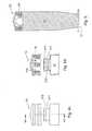
Fig. 2 , there is shown a genericportable pump 31 for drug infusion, equipped with anut 33 for receivingrear wings 23 of asyringe 11 and consequently enabling the syringe to be associated with the pump, and with apusher 35 having ahead 37 shaped so as to be able to engage the plunger of a syringe associated with the pump. - Turning now to
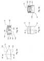
Figs. 3a and 3b ,plunger 13 comprises a corresponding hollow cylindrical body in which adome 132 closing one the cylinder bases and anopening 133 formed in the opposite base are defined. Acircumferential groove 139 is provided around the cylindrical body ofplunger 13 to accommodate ring-shapedgasket 19. - A
seat 134 is provided insideplunger 13 and has defined therein the joint for the head of rod 15 and/or, as it will disclosed later on, for the head of the pusher of an infusion pump. - In the example illustrated, the joint defined inside
seat 134 ofplunger 13 is formed by fourlongitudinal extensions 135, arranged along a circumference and mutually spaced apart by 90°. - In the alternative, said joint could be formed externally of the body of
plunger 13, in whichcase extensions 135 will be located externally of the body ofplunger 13, which preferably will be closed at both ends. - For reasons that will be better understood later on, each
extension 135 has astem 136 secured todome 132 internally ofseat 134 and ending in atooth 137 radially directed towards the centre ofseat 134, and alongitudinal groove 138 formed on the face ofstem 136 opposite totooth 137. - Referring to
Figs. 4a to 4d , there is shown the situation of use ofplunger 13 coupled withhead 37 ofpusher 35 of a drug infusion pump, such aspump 31 shown inFig. 2 . - Advantageously, thanks to the joint defined inside
seat 134,plunger 13 can accommodatehead 37 of the pusher of a drug infusion pump betweenlongitudinal extensions 135. - Still referring to
Figs. 4a to 4d ,head 37 ofpusher 35 of a drug infusion pump generally comprises acylindrical body 371, having anaxial bore 372 enablingfastening head 37 to the rod (not shown) of the pusher of the pump, by means of a screw or other fastening means. The outer end of the cylindrical body ofhead 37 further has a widenededge 373 that, in case of plungers made of rubber, enables retaining the plunger against the pusher head thanks to the deformation of the material, in order to hinder phenomena of free flow. - Advantageously, according to the invention, the widened edge of
head 37 is retained insideseat 134 ofplunger 13 thanks toteeth 137 provided at the base oflongitudinal extensions 135 that, in order to enable insertion ofhead 37, will preferably be resiliently flexible in radial direction towards the outside ofseat 134. - Advantageously,
teeth 137 preventplunger 13 from being disconnected fromhead 37 of the pusher in axial direction, thereby avoiding the danger of free flow of the drug while the pump is being used in its normal operating conditions. - Application in axial direction of a force higher than the force that could determine free flow phenomena allows instead an easy separation of the plunger from the pump at the end of the delivery of the drug.
- Turning to
Fig. 4e , there is shown a first variant embodiment of the plunger, here generally denoted 413. - According to that variant embodiment,
plunger 413 has a pair ofcircumferential grooves 439 for receiving respective O-rings 419. - Also in that embodiment,
plunger 413 can advantageously be made of thermoplastic material withgaskets 419 made of elastomeric material in order to ensure the necessary seal. - Turning now to
Figs. 5 to 8 , rod 15 of the syringe according to the invention is shown in greater detail. The rod comprises, at its forward end intended to engageplunger 13, a disc-shapedbase 151 from which a centralcylindrical projection 152 and a pair of diametrically opposite arc-shapedprojections 153, located externally ofprojection 152, extend axially upwards. - There is provided a first pair of radial stops 154, radially extending from the forward base of
cylindrical projection 152, and a second pair ofaxial stops 155 extending from the side wall ofprojection 152, said axial stops being joined to the disc-shaped base. In the alternative, said axial stops can be joined only either to base 151 or tocylindrical projection 152. - For reasons that will be explained later on, arc-shaped
projections 153 include a centrallongitudinal projection 156, radial stops 154 are arranged along a diameter passing through the central axis ofcylindrical projection 152 andaxial stops 155 are mutually offset, that is they are arranged along the direction of two respective chords ofcylindrical projection 152. - Coupling of rod 15 with
plunger 13 takes place through a first translational movement bringing the two parts closer together in axial direction, during which movementcylindrical projection 152, arc-shapedprojections 153, radial stops 154 andaxial stops 155 penetrate intoseat 134, and through a second rotary movement, at the end of which radial stops 154 are located in correspondence of two respectivelongitudinal extensions 135 ofplunger 13,axial stops 155 abut against the other two extensions and arc-shapedprojections 153 are located in correspondence of the two first-mentionedlongitudinal extensions 135, with their respective longitudinal extensions engaged within the correspondinggrooves 138. - In such a configuration,
teeth 137 ofextensions 135 located in correspondence of radial stops 154 prevent the rod from disconnecting from the plunger while the drug is being drawn into the syringe. Rotation of the rod relative to the plunger at the end of the drawing of the drug and the subsequent separation are on the contrary simple operations that can be easily carried out even by aged patients. Figs. 4f and4g show a second variant embodiment of the plunger, here generally denoted 513.Plunger 513 includes aseat 534 having a joint forhead 37 of the pusher of a pump and athread 540 for threadedhead 552 ofrod 515 of a syringe.- The joint defined inside
seat 534 inplunger 513 is formed by fourlongitudinal extensions 535, substantially identical to the extensions described in connection with the first embodiment of the invention. - In this second variant embodiment,
longitudinal extensions 535 preferably extend over only part of the length of seat 34, so as to leave an initial free portion for screwingrod 515. - Said
rod 515 can comprise an axially bored threadedhead 552, where saidextensions 535 are received whenrod 515 is wholly screwed intoseat 534. - Thanks to this second variant embodiment of the invention, the coupling of the rod with the plunger may take place in conventional way, i.e. by screwing, while maintaining the coupling of the plunger onto the pusher through an axial translational movement.
- The plunger according to the invention can be advantageously be used not only for a syringe where the liquid is to be previously drawn before the injection, but also for a phial already pre-filled with a liquid to be injected.
Claims (15)
- A combination of a syringe rod (15) arranged to cooperate with a plunger and a syringe plunger, said plunger comprising engagement means (137) for retaining the head of the rod (15) or a pusher (35) of an infusion pump at the end of an axial translational coupling movement or an axial translational and rotary coupling movement of said plunger and said rod or pusher relative to each other, said rod comprising at a forward end intended to engage the plunger (13) a base (151) from which a central cylindrical projection (152) extends axially upwards and a first pair of radial stops (154), radially extending from said cylindrical projection (152),characterized in that said rod further comprises at said forward end:- a pair of arc-shaped projections (153), diametrically opposed and arranged externally of said central cylindrical projection (152), extending axially upwards from said base (151); and- a second pair of axial stops (155).
- A combination as claimed in claim 1, wherein said base (151) is disc shaped.
- A combination as claimed in claim 1, wherein said axial stops (155) are joined to said base and/or to said cylindrical projection.
- A combination as claimed in claim 1, wherein said arc-shaped projections (153) include a central longitudinal projection (156).
- A combination as claimed in claim 1, wherein said radial stops (154) are arranged along a diameter passing through the central axis of the cylindrical projection (152).
- A combination as claimed in claim 1, wherein said axial stops (155) are mutually offset, i.e. they are arranged along two respective chords of the cylindrical projection (152).
- A combination as claimed in any of the preceding claims, wherein said plunger comprises a substantially cylindrical hollow body having a closed base and an opening located in correspondence of the opposite base, and wherein a seat (134) is provided which is accessible through said opening in order to receive the head of a rod or a pusher (15; 35), said engagement means (137) being housed inside said seat (134).
- A combination as claimed in claim 7, wherein said engagement means (137) comprise at least one pair of extensions (135), each having a stem (136) axially extending within said seat (134) and ending in a tooth (137) radially extending towards the centre of said seat (134).
- A combination as claimed in claim 8, wherein four extensions are provided, which are mutually spaced apart by 90° along a circumference.
- A combination as claimed in claim 9, wherein said extensions have a longitudinal groove (138) formed on the face of the stem (136) opposite to the tooth (137).
- A combination as claimed in claim 7, wherein a dome (132) extends from said hollow cylindrical body and closes one of the cylinder bases.
- A combination as claimed in any preceding claim, wherein said plunger (13) is equipped with a ring-shaped sealing gasket (19).
- A combination as claimed in any claims from 7 to 11, wherein said body of the plunger is made of thermoplastic material.
- A syringe comprising a cylindrical hollow barrel and a combination of a rod (15) and a plunger (13) slidable within the syringe barrel in a first direction in order to draw liquid through a first opening (21) provided at one end of the syringe barrel, and in a second direction in order to inject through the same opening (21) the liquid previously drawn,characterised in that said combination of rod (15) and plunger (13) is a combination as claimed in any of claims 1 to 13.
- A phial pre-filled with a liquid, comprising a cylindrical hollow body and a combination of a rod (15) and a plunger (13) which is slidable within the phial body in order to inject the liquid through an opening (21) provided at one end of the phial body,characterised in that said combination of a rod (15) and a plunger (13) is a combination as claimed in any of claims 1 to 13.
Applications Claiming Priority (2)
| Application Number | Priority Date | Filing Date | Title |
|---|---|---|---|
| IT000816AITTO20060816A1 (en) | 2006-11-16 | 2006-11-16 | STRIPE FOR SYRINGE AND SYRINGE THAT ENCOURAGES THE STOVE |
| PCT/IB2007/054627WO2008059448A2 (en) | 2006-11-16 | 2007-11-14 | Syringe plunger and syringe incorporating the plunger. |
Publications (2)
| Publication Number | Publication Date |
|---|---|
| EP2094338A2 EP2094338A2 (en) | 2009-09-02 |
| EP2094338B1true EP2094338B1 (en) | 2011-06-15 |
Family
ID=39325635
Family Applications (1)
| Application Number | Title | Priority Date | Filing Date |
|---|---|---|---|
| EP07849126AActiveEP2094338B1 (en) | 2006-11-16 | 2007-11-14 | Syringe plunger and syringe incorporating the plunger. |
Country Status (5)
| Country | Link |
|---|---|
| US (1) | US8172814B2 (en) |
| EP (1) | EP2094338B1 (en) |
| AT (1) | ATE512684T1 (en) |
| IT (1) | ITTO20060816A1 (en) |
| WO (1) | WO2008059448A2 (en) |
Families Citing this family (37)
| Publication number | Priority date | Publication date | Assignee | Title |
|---|---|---|---|---|
| AUPQ867900A0 (en) | 2000-07-10 | 2000-08-03 | Medrad, Inc. | Medical injector system |
| US7666169B2 (en) | 2003-11-25 | 2010-02-23 | Medrad, Inc. | Syringe and syringe plungers for use with medical injectors |
| USD1031029S1 (en) | 2003-11-25 | 2024-06-11 | Bayer Healthcare Llc | Syringe plunger |
| US8926569B2 (en) | 2006-03-15 | 2015-01-06 | Bayer Medical Care Inc. | Plunger covers and plungers for use in syringes and methods of fabricating plunger covers and plungers for use in syringes |
| USD659234S1 (en)* | 2006-08-11 | 2012-05-08 | Cane S.R.L. | Drug infusion device with a protective cap |
| USD847985S1 (en) | 2007-03-14 | 2019-05-07 | Bayer Healthcare Llc | Syringe plunger cover |
| USD942005S1 (en) | 2007-03-14 | 2022-01-25 | Bayer Healthcare Llc | Orange syringe plunger cover |
| US8167846B2 (en)* | 2009-07-08 | 2012-05-01 | Medtronic Minimed, Inc. | Reservoir filling systems and methods |
| US8932256B2 (en) | 2009-09-02 | 2015-01-13 | Medtronic Minimed, Inc. | Insertion device systems and methods |
| US11497850B2 (en) | 2009-12-30 | 2022-11-15 | Medtronic Minimed, Inc. | Connection and alignment detection systems and methods |
| KR200451044Y1 (en) | 2010-06-29 | 2010-11-19 | 김기원 | Reusable disposable syringe with anti-rotation structure of plunger |
| US9174003B2 (en) | 2012-09-28 | 2015-11-03 | Bayer Medical Care Inc. | Quick release plunger |
| AU2015231396B2 (en) | 2014-03-19 | 2018-12-06 | Bayer Healthcare Llc | System for syringe engagement to an injector |
| JP2015226578A (en)* | 2014-05-30 | 2015-12-17 | 株式会社 ユニフローズ | Syringe |
| GB2529621B (en)* | 2014-08-21 | 2016-12-07 | Owen Mumford Ltd | Safety syringe |
| US10035526B2 (en)* | 2014-12-03 | 2018-07-31 | New York Air Brake, LLC | Brake piston assembly |
| BR112017011058A2 (en)* | 2014-12-03 | 2018-01-02 | New York Air Brake Llc | enhanced brake piston assembly |
| US10842930B2 (en) | 2015-08-04 | 2020-11-24 | Cane' S.P.A. | Device for infusing a fluid substance to the body of a living being |
| WO2017047295A1 (en)* | 2015-09-17 | 2017-03-23 | テルモ株式会社 | Syringe plunger and pre-filled syringe using same |
| US9480797B1 (en) | 2015-10-28 | 2016-11-01 | Bayer Healthcare Llc | System and method for syringe plunger engagement with an injector |
| US11325235B2 (en) | 2016-06-28 | 2022-05-10 | Black & Decker, Inc. | Push-on support member for fastening tools |
| US11267114B2 (en) | 2016-06-29 | 2022-03-08 | Black & Decker, Inc. | Single-motion magazine retention for fastening tools |
| US11279013B2 (en) | 2016-06-30 | 2022-03-22 | Black & Decker, Inc. | Driver rebound plate for a fastening tool |
| US10987790B2 (en) | 2016-06-30 | 2021-04-27 | Black & Decker Inc. | Cordless concrete nailer with improved power take-off mechanism |
| US11400572B2 (en) | 2016-06-30 | 2022-08-02 | Black & Decker, Inc. | Dry-fire bypass for a fastening tool |
| WO2018043356A1 (en)* | 2016-09-05 | 2018-03-08 | 内外化成株式会社 | Syringe plunger, method of manufacturing same, and medical syringe |
| US11684711B2 (en) | 2016-12-13 | 2023-06-27 | Cane' S.P.A. | Housing for a cartridge for distribution and administration of drugs by means of portable infusion pumps |
| HUE063479T2 (en) | 2017-01-06 | 2024-01-28 | Bayer Healthcare Llc | Syringe plunger with dynamic seal |
| US10926385B2 (en) | 2017-02-24 | 2021-02-23 | Black & Decker, Inc. | Contact trip having magnetic filter |
| HUE061426T2 (en) | 2018-02-27 | 2023-06-28 | Bayer Healthcare Llc | Syringe piston switch mechanism |
| IT201800006427A1 (en) | 2018-06-18 | 2019-12-18 | Compact, quick-charge safety pump for drug administration | |
| EP3593838A1 (en)* | 2018-07-13 | 2020-01-15 | Zyno Medical, Llc | High precision syringe with removable pump unit |
| US11679205B2 (en)* | 2018-07-13 | 2023-06-20 | Zyno Medical Llc | High precision syringe with removable pump unit |
| US12246161B2 (en) | 2018-12-31 | 2025-03-11 | Cane' S.P.A. | Shell for a portable electromechanical apparatus for drug infusion |
| BR112022023788A2 (en) | 2020-06-18 | 2022-12-27 | Bayer Healthcare Llc | SYSTEM AND METHOD OF COUPLING A SYRINGE PLUNGER WITH AN INJECTOR |
| US20240325630A1 (en)* | 2020-08-25 | 2024-10-03 | Eoflow Co., Ltd. | Apparatus for infusing medical liquid |
| US12042624B2 (en) | 2021-08-12 | 2024-07-23 | Cane' S.P.A. | Manually operated mechanical pump for drug infusion |
Family Cites Families (32)
| Publication number | Priority date | Publication date | Assignee | Title |
|---|---|---|---|---|
| ATE51525T1 (en)* | 1984-06-06 | 1990-04-15 | Medrad Inc | ANGIOGRAPHY INJECTOR AND ANGIOGRAPHY SYRINGE USABLE WITH THEM. |
| US4973308A (en)* | 1987-05-22 | 1990-11-27 | Ramon M. Rovira | Injection syringe with mechanism preventing reuse |
| US5085639A (en)* | 1988-03-01 | 1992-02-04 | Ryan Medical, Inc. | Safety winged needle medical devices |
| FR2628635B1 (en)* | 1988-03-21 | 1992-10-23 | Microtechnic Sa | SINGLE USE SYRINGE |
| US4931043A (en)* | 1988-08-08 | 1990-06-05 | Sterling Drug Inc. | Ratchet connector for hypodermic syringe pistons |
| US4911695A (en)* | 1989-04-03 | 1990-03-27 | Coeur Laboratories, Inc. | Plunger for power-driven angiographic syringe, and syringe and power injector system utilizing same |
| US5094148A (en)* | 1989-05-08 | 1992-03-10 | Habley Medical Technology Corporation | Piston stem insert for a carpule based piston |
| US5084017A (en)* | 1989-10-10 | 1992-01-28 | John Maffetone | Self disabling, single use, hypodermic syringe |
| AU661310B2 (en)* | 1991-04-22 | 1995-07-20 | Nils Goran Helldin | A syringe, including a rod and a piston |
| US5352200A (en)* | 1991-12-05 | 1994-10-04 | Roy Hammett | Non-reusable syringe with needle guard |
| US5181912A (en)* | 1991-12-05 | 1993-01-26 | Roy Hammett | Non-reusable syringe |
| SE9202052L (en)* | 1992-07-02 | 1994-01-03 | Goeran Helldin | A rod and piston unit useful in a disposable syringe and a way of mounting a syringe while utilizing such a unit |
| SE469742B (en)* | 1992-08-25 | 1993-09-06 | Nils Goeran Helldin | SYRINGE |
| US5413563A (en)* | 1994-05-06 | 1995-05-09 | Sterling Winthrop Inc. | Pre-filled syringe having a plunger, plunger insert and plunger rod |
| US5688252A (en)* | 1994-09-30 | 1997-11-18 | Takeda Chemical Industries, Ltd. | Syringe |
| US6120479A (en)* | 1996-01-26 | 2000-09-19 | Campbell; Douglas C. V. | Auto-destruct disposable syringe |
| US5947935A (en)* | 1996-11-12 | 1999-09-07 | Medrad, Inc. | Syringes, syringe plungers and injector systems |
| US5873861A (en)* | 1996-11-12 | 1999-02-23 | Medrad, Inc. | Plunger systems |
| US6764466B1 (en)* | 1997-07-18 | 2004-07-20 | Liebel Flarsheim Company | Adapter and syringe for front-loading medical fluid injector |
| US5947929A (en)* | 1997-08-22 | 1999-09-07 | Coeur Laboratories, Inc. | Front-load angiographic injector system, angiographic syringe and plunger for angiographic syringe |
| EP0925798B1 (en)* | 1997-12-24 | 2003-05-14 | Bracco International B.V. | Easy-slip plunger/plunger rod assembly for a syringe or a cartridge |
| US7798993B2 (en)* | 1998-07-29 | 2010-09-21 | Becton, Dickinson And Company | Single use syringe |
| IT1307266B1 (en) | 1999-08-13 | 2001-10-30 | Cane Srl | APPARATUS FOR INFUSION OF DRUGS. |
| US6676642B2 (en)* | 2000-07-10 | 2004-01-13 | Fishman Corporation | Barrel stabilizer for syringe piston |
| BR8101570U (en)* | 2001-07-25 | 2003-06-10 | Roberto Yassuo Ito | Disposable syringe with stem rupture |
| US7033338B2 (en)* | 2002-02-28 | 2006-04-25 | Smiths Medical Md, Inc. | Cartridge and rod for axially loading medication pump |
| US6773416B1 (en)* | 2003-02-25 | 2004-08-10 | Fu-Yu Hsu | Safety hypodermic syringe |
| US7179243B2 (en)* | 2003-05-09 | 2007-02-20 | Cho Ying Chen | Syringe with a snapping device for backward pulling the needle into the syringe after syringing |
| DE10330094B4 (en)* | 2003-07-03 | 2008-04-17 | Disetronic Licensing Ag | Device for administering a liquid product |
| US7666169B2 (en) | 2003-11-25 | 2010-02-23 | Medrad, Inc. | Syringe and syringe plungers for use with medical injectors |
| WO2006087762A1 (en)* | 2005-02-15 | 2006-08-24 | Kabushiki Kaisha Top | Syringe |
| US8038656B2 (en)* | 2006-09-29 | 2011-10-18 | Tyco Healthcare Group Lp | Detachable plunger rod syringe |
- 2006
- 2006-11-16ITIT000816Apatent/ITTO20060816A1/enunknown
- 2007
- 2007-11-14USUS12/514,543patent/US8172814B2/enactiveActive
- 2007-11-14WOPCT/IB2007/054627patent/WO2008059448A2/enactiveApplication Filing
- 2007-11-14EPEP07849126Apatent/EP2094338B1/enactiveActive
- 2007-11-14ATAT07849126Tpatent/ATE512684T1/ennot_activeIP Right Cessation
Also Published As
| Publication number | Publication date |
|---|---|
| WO2008059448A3 (en) | 2008-08-21 |
| WO2008059448A2 (en) | 2008-05-22 |
| US8172814B2 (en) | 2012-05-08 |
| US20100057014A1 (en) | 2010-03-04 |
| ATE512684T1 (en) | 2011-07-15 |
| ITTO20060816A1 (en) | 2008-05-17 |
| EP2094338A2 (en) | 2009-09-02 |
Similar Documents
| Publication | Publication Date | Title |
|---|---|---|
| EP2094338B1 (en) | Syringe plunger and syringe incorporating the plunger. | |
| US8551045B2 (en) | Fluid infusion system, a method of assembling such system and drug reservoir for use in the system | |
| EP2774637B1 (en) | Cartridge interface assembly | |
| CA2207991C (en) | Filling device for a needleless injector cartridge | |
| CN101426546B (en) | A fluid infusion system, a method of assembling such system and drug reservoir for use in the system | |
| CN101511410B (en) | Medical delivery systems suitable for axial locking and rotational release | |
| JP6321635B2 (en) | Medical infusion device | |
| US20010051793A1 (en) | Filling device for a needleless injector cartridge | |
| JP2001145697A (en) | Syringe which can be filled in advance, and plunger and injector to be used with it | |
| CN213852500U (en) | prefillable container | |
| US9802002B2 (en) | Training cartridge for a drug delivery device | |
| JP2019509131A (en) | Injector with reduced release force | |
| JP6963544B2 (en) | Administration unit with low radial sealing during storage | |
| US9833568B2 (en) | Compression element driven fluid delivery apparatus | |
| US11925793B2 (en) | Apparatus for injecting a fluid, comprising a needle assembly and a needle retention device for retaining a needle of the needle assembly when attached to the apparatus, and needle retention device | |
| US20240131261A1 (en) | Low Dead Volume Adaptor for a Syringe |
Legal Events
| Date | Code | Title | Description |
|---|---|---|---|
| PUAI | Public reference made under article 153(3) epc to a published international application that has entered the european phase | Free format text:ORIGINAL CODE: 0009012 | |
| 17P | Request for examination filed | Effective date:20090616 | |
| AK | Designated contracting states | Kind code of ref document:A2 Designated state(s):AT BE BG CH CY CZ DE DK EE ES FI FR GB GR HU IE IS IT LI LT LU LV MC MT NL PL PT RO SE SI SK TR | |
| DAX | Request for extension of the european patent (deleted) | ||
| 17Q | First examination report despatched | Effective date:20100222 | |
| GRAP | Despatch of communication of intention to grant a patent | Free format text:ORIGINAL CODE: EPIDOSNIGR1 | |
| GRAS | Grant fee paid | Free format text:ORIGINAL CODE: EPIDOSNIGR3 | |
| GRAA | (expected) grant | Free format text:ORIGINAL CODE: 0009210 | |
| AK | Designated contracting states | Kind code of ref document:B1 Designated state(s):AT BE BG CH CY CZ DE DK EE ES FI FR GB GR HU IE IS IT LI LT LU LV MC MT NL PL PT RO SE SI SK TR | |
| REG | Reference to a national code | Ref country code:CH Ref legal event code:EP Ref country code:GB Ref legal event code:FG4D | |
| REG | Reference to a national code | Ref country code:IE Ref legal event code:FG4D | |
| REG | Reference to a national code | Ref country code:DE Ref legal event code:R096 Ref document number:602007015286 Country of ref document:DE Effective date:20110804 | |
| REG | Reference to a national code | Ref country code:NL Ref legal event code:VDEP Effective date:20110615 | |
| PG25 | Lapsed in a contracting state [announced via postgrant information from national office to epo] | Ref country code:SE Free format text:LAPSE BECAUSE OF FAILURE TO SUBMIT A TRANSLATION OF THE DESCRIPTION OR TO PAY THE FEE WITHIN THE PRESCRIBED TIME-LIMIT Effective date:20110615 Ref country code:LT Free format text:LAPSE BECAUSE OF FAILURE TO SUBMIT A TRANSLATION OF THE DESCRIPTION OR TO PAY THE FEE WITHIN THE PRESCRIBED TIME-LIMIT Effective date:20110615 | |
| PG25 | Lapsed in a contracting state [announced via postgrant information from national office to epo] | Ref country code:CY Free format text:LAPSE BECAUSE OF FAILURE TO SUBMIT A TRANSLATION OF THE DESCRIPTION OR TO PAY THE FEE WITHIN THE PRESCRIBED TIME-LIMIT Effective date:20110615 Ref country code:AT Free format text:LAPSE BECAUSE OF FAILURE TO SUBMIT A TRANSLATION OF THE DESCRIPTION OR TO PAY THE FEE WITHIN THE PRESCRIBED TIME-LIMIT Effective date:20110615 Ref country code:SI Free format text:LAPSE BECAUSE OF FAILURE TO SUBMIT A TRANSLATION OF THE DESCRIPTION OR TO PAY THE FEE WITHIN THE PRESCRIBED TIME-LIMIT Effective date:20110615 Ref country code:LV Free format text:LAPSE BECAUSE OF FAILURE TO SUBMIT A TRANSLATION OF THE DESCRIPTION OR TO PAY THE FEE WITHIN THE PRESCRIBED TIME-LIMIT Effective date:20110615 Ref country code:FI Free format text:LAPSE BECAUSE OF FAILURE TO SUBMIT A TRANSLATION OF THE DESCRIPTION OR TO PAY THE FEE WITHIN THE PRESCRIBED TIME-LIMIT Effective date:20110615 Ref country code:GR Free format text:LAPSE BECAUSE OF FAILURE TO SUBMIT A TRANSLATION OF THE DESCRIPTION OR TO PAY THE FEE WITHIN THE PRESCRIBED TIME-LIMIT Effective date:20110916 | |
| PG25 | Lapsed in a contracting state [announced via postgrant information from national office to epo] | Ref country code:NL Free format text:LAPSE BECAUSE OF FAILURE TO SUBMIT A TRANSLATION OF THE DESCRIPTION OR TO PAY THE FEE WITHIN THE PRESCRIBED TIME-LIMIT Effective date:20110615 Ref country code:BE Free format text:LAPSE BECAUSE OF FAILURE TO SUBMIT A TRANSLATION OF THE DESCRIPTION OR TO PAY THE FEE WITHIN THE PRESCRIBED TIME-LIMIT Effective date:20110615 | |
| PG25 | Lapsed in a contracting state [announced via postgrant information from national office to epo] | Ref country code:IS Free format text:LAPSE BECAUSE OF FAILURE TO SUBMIT A TRANSLATION OF THE DESCRIPTION OR TO PAY THE FEE WITHIN THE PRESCRIBED TIME-LIMIT Effective date:20111015 Ref country code:CZ Free format text:LAPSE BECAUSE OF FAILURE TO SUBMIT A TRANSLATION OF THE DESCRIPTION OR TO PAY THE FEE WITHIN THE PRESCRIBED TIME-LIMIT Effective date:20110615 Ref country code:EE Free format text:LAPSE BECAUSE OF FAILURE TO SUBMIT A TRANSLATION OF THE DESCRIPTION OR TO PAY THE FEE WITHIN THE PRESCRIBED TIME-LIMIT Effective date:20110615 Ref country code:PT Free format text:LAPSE BECAUSE OF FAILURE TO SUBMIT A TRANSLATION OF THE DESCRIPTION OR TO PAY THE FEE WITHIN THE PRESCRIBED TIME-LIMIT Effective date:20111017 | |
| PG25 | Lapsed in a contracting state [announced via postgrant information from national office to epo] | Ref country code:SK Free format text:LAPSE BECAUSE OF FAILURE TO SUBMIT A TRANSLATION OF THE DESCRIPTION OR TO PAY THE FEE WITHIN THE PRESCRIBED TIME-LIMIT Effective date:20110615 Ref country code:PL Free format text:LAPSE BECAUSE OF FAILURE TO SUBMIT A TRANSLATION OF THE DESCRIPTION OR TO PAY THE FEE WITHIN THE PRESCRIBED TIME-LIMIT Effective date:20110615 Ref country code:RO Free format text:LAPSE BECAUSE OF FAILURE TO SUBMIT A TRANSLATION OF THE DESCRIPTION OR TO PAY THE FEE WITHIN THE PRESCRIBED TIME-LIMIT Effective date:20110615 | |
| PLBE | No opposition filed within time limit | Free format text:ORIGINAL CODE: 0009261 | |
| STAA | Information on the status of an ep patent application or granted ep patent | Free format text:STATUS: NO OPPOSITION FILED WITHIN TIME LIMIT | |
| 26N | No opposition filed | Effective date:20120316 | |
| PG25 | Lapsed in a contracting state [announced via postgrant information from national office to epo] | Ref country code:MC Free format text:LAPSE BECAUSE OF NON-PAYMENT OF DUE FEES Effective date:20111130 Ref country code:DK Free format text:LAPSE BECAUSE OF FAILURE TO SUBMIT A TRANSLATION OF THE DESCRIPTION OR TO PAY THE FEE WITHIN THE PRESCRIBED TIME-LIMIT Effective date:20110615 | |
| REG | Reference to a national code | Ref country code:CH Ref legal event code:PL | |
| REG | Reference to a national code | Ref country code:DE Ref legal event code:R097 Ref document number:602007015286 Country of ref document:DE Effective date:20120316 | |
| PG25 | Lapsed in a contracting state [announced via postgrant information from national office to epo] | Ref country code:LI Free format text:LAPSE BECAUSE OF NON-PAYMENT OF DUE FEES Effective date:20111130 Ref country code:CH Free format text:LAPSE BECAUSE OF NON-PAYMENT OF DUE FEES Effective date:20111130 | |
| REG | Reference to a national code | Ref country code:IE Ref legal event code:MM4A | |
| PG25 | Lapsed in a contracting state [announced via postgrant information from national office to epo] | Ref country code:IE Free format text:LAPSE BECAUSE OF NON-PAYMENT OF DUE FEES Effective date:20111114 | |
| PG25 | Lapsed in a contracting state [announced via postgrant information from national office to epo] | Ref country code:MT Free format text:LAPSE BECAUSE OF FAILURE TO SUBMIT A TRANSLATION OF THE DESCRIPTION OR TO PAY THE FEE WITHIN THE PRESCRIBED TIME-LIMIT Effective date:20110615 | |
| PG25 | Lapsed in a contracting state [announced via postgrant information from national office to epo] | Ref country code:ES Free format text:LAPSE BECAUSE OF FAILURE TO SUBMIT A TRANSLATION OF THE DESCRIPTION OR TO PAY THE FEE WITHIN THE PRESCRIBED TIME-LIMIT Effective date:20110926 | |
| PG25 | Lapsed in a contracting state [announced via postgrant information from national office to epo] | Ref country code:LU Free format text:LAPSE BECAUSE OF NON-PAYMENT OF DUE FEES Effective date:20111114 | |
| PG25 | Lapsed in a contracting state [announced via postgrant information from national office to epo] | Ref country code:BG Free format text:LAPSE BECAUSE OF FAILURE TO SUBMIT A TRANSLATION OF THE DESCRIPTION OR TO PAY THE FEE WITHIN THE PRESCRIBED TIME-LIMIT Effective date:20110915 | |
| PG25 | Lapsed in a contracting state [announced via postgrant information from national office to epo] | Ref country code:TR Free format text:LAPSE BECAUSE OF FAILURE TO SUBMIT A TRANSLATION OF THE DESCRIPTION OR TO PAY THE FEE WITHIN THE PRESCRIBED TIME-LIMIT Effective date:20110615 | |
| PG25 | Lapsed in a contracting state [announced via postgrant information from national office to epo] | Ref country code:HU Free format text:LAPSE BECAUSE OF FAILURE TO SUBMIT A TRANSLATION OF THE DESCRIPTION OR TO PAY THE FEE WITHIN THE PRESCRIBED TIME-LIMIT Effective date:20110615 | |
| REG | Reference to a national code | Ref country code:DE Ref legal event code:R082 Ref document number:602007015286 Country of ref document:DE Representative=s name:PATENTANWAELTE JABBUSCH SIEKMANN & WASILJEFF, DE | |
| REG | Reference to a national code | Ref country code:GB Ref legal event code:S117 Free format text:REQUEST FILED; REQUEST FOR CORRECTION UNDER SECTION 117 FILED ON 23 JANUARY 2015. | |
| REG | Reference to a national code | Ref country code:FR Ref legal event code:CA Effective date:20150204 Ref country code:FR Ref legal event code:CD Owner name:CANE' S.P.A., IT Effective date:20150204 | |
| REG | Reference to a national code | Ref country code:GB Ref legal event code:S117 Free format text:CORRECTIONS ALLOWED; REQUEST FOR CORRECTION UNDER SECTION 117 FILED ON 23 JANUARY 2015, ALLOWED ON 16 FEBRUARY 2015. | |
| REG | Reference to a national code | Ref country code:DE Ref legal event code:R082 Ref document number:602007015286 Country of ref document:DE Representative=s name:PATENTANWAELTE JABBUSCH SIEKMANN & WASILJEFF, DE Effective date:20150130 Ref country code:DE Ref legal event code:R081 Ref document number:602007015286 Country of ref document:DE Owner name:CANE' S.P.A., RIVOLI, IT Free format text:FORMER OWNER: CANE' S.P.A. - SOCIO UNICO, 10098 RIVOLI, IT Effective date:20150130 | |
| REG | Reference to a national code | Ref country code:FR Ref legal event code:PLFP Year of fee payment:9 | |
| REG | Reference to a national code | Ref country code:FR Ref legal event code:PLFP Year of fee payment:10 | |
| REG | Reference to a national code | Ref country code:FR Ref legal event code:PLFP Year of fee payment:11 | |
| PGFP | Annual fee paid to national office [announced via postgrant information from national office to epo] | Ref country code:DE Payment date:20241030 Year of fee payment:18 | |
| PGFP | Annual fee paid to national office [announced via postgrant information from national office to epo] | Ref country code:GB Payment date:20241129 Year of fee payment:18 | |
| PGFP | Annual fee paid to national office [announced via postgrant information from national office to epo] | Ref country code:FR Payment date:20241127 Year of fee payment:18 | |
| PGFP | Annual fee paid to national office [announced via postgrant information from national office to epo] | Ref country code:IT Payment date:20241120 Year of fee payment:18 |