EP2093408A1 - Tank pressurised by heated gases - Google Patents
Tank pressurised by heated gasesDownload PDFInfo
- Publication number
- EP2093408A1 EP2093408A1EP09152768AEP09152768AEP2093408A1EP 2093408 A1EP2093408 A1EP 2093408A1EP 09152768 AEP09152768 AEP 09152768AEP 09152768 AEP09152768 AEP 09152768AEP 2093408 A1EP2093408 A1EP 2093408A1
- Authority
- EP
- European Patent Office
- Prior art keywords
- piston
- liquid
- chamber
- tank
- wall
- Prior art date
- Legal status (The legal status is an assumption and is not a legal conclusion. Google has not performed a legal analysis and makes no representation as to the accuracy of the status listed.)
- Granted
Links
- 239000007789gasSubstances0.000titledescription17
- 239000007788liquidSubstances0.000claimsabstractdescription31
- 239000012528membraneSubstances0.000claimsabstractdescription24
- 239000000843powderSubstances0.000claimsabstractdescription8
- 238000007599dischargingMethods0.000claims1
- 239000003380propellantSubstances0.000abstractdescription4
- 229920001971elastomerPolymers0.000abstractdescription3
- 238000007789sealingMethods0.000abstractdescription2
- 239000000806elastomerSubstances0.000abstract1
- 230000004888barrier functionEffects0.000description3
- 230000000694effectsEffects0.000description3
- 239000002184metalSubstances0.000description3
- 238000006073displacement reactionMethods0.000description2
- 230000000295complement effectEffects0.000description1
- 238000001816coolingMethods0.000description1
- 230000003247decreasing effectEffects0.000description1
- 230000001627detrimental effectEffects0.000description1
- 239000013536elastomeric materialSubstances0.000description1
- 238000010438heat treatmentMethods0.000description1
- 239000003999initiatorSubstances0.000description1
- 230000014759maintenance of locationEffects0.000description1
- 238000005457optimizationMethods0.000description1
- 229920000642polymerPolymers0.000description1
Images


Classifications
- F—MECHANICAL ENGINEERING; LIGHTING; HEATING; WEAPONS; BLASTING
- F02—COMBUSTION ENGINES; HOT-GAS OR COMBUSTION-PRODUCT ENGINE PLANTS
- F02K—JET-PROPULSION PLANTS
- F02K9/00—Rocket-engine plants, i.e. plants carrying both fuel and oxidant therefor; Control thereof
- F02K9/42—Rocket-engine plants, i.e. plants carrying both fuel and oxidant therefor; Control thereof using liquid or gaseous propellants
- F02K9/60—Constructional parts; Details not otherwise provided for
- F02K9/605—Reservoirs
- F—MECHANICAL ENGINEERING; LIGHTING; HEATING; WEAPONS; BLASTING
- F02—COMBUSTION ENGINES; HOT-GAS OR COMBUSTION-PRODUCT ENGINE PLANTS
- F02K—JET-PROPULSION PLANTS
- F02K9/00—Rocket-engine plants, i.e. plants carrying both fuel and oxidant therefor; Control thereof
- F02K9/42—Rocket-engine plants, i.e. plants carrying both fuel and oxidant therefor; Control thereof using liquid or gaseous propellants
- F02K9/44—Feeding propellants
- F02K9/50—Feeding propellants using pressurised fluid to pressurise the propellants
- F—MECHANICAL ENGINEERING; LIGHTING; HEATING; WEAPONS; BLASTING
- F05—INDEXING SCHEMES RELATING TO ENGINES OR PUMPS IN VARIOUS SUBCLASSES OF CLASSES F01-F04
- F05D—INDEXING SCHEME FOR ASPECTS RELATING TO NON-POSITIVE-DISPLACEMENT MACHINES OR ENGINES, GAS-TURBINES OR JET-PROPULSION PLANTS
- F05D2300/00—Materials; Properties thereof
- F05D2300/40—Organic materials
- F05D2300/43—Synthetic polymers, e.g. plastics; Rubber
- F05D2300/431—Rubber
- F—MECHANICAL ENGINEERING; LIGHTING; HEATING; WEAPONS; BLASTING
- F05—INDEXING SCHEMES RELATING TO ENGINES OR PUMPS IN VARIOUS SUBCLASSES OF CLASSES F01-F04
- F05D—INDEXING SCHEME FOR ASPECTS RELATING TO NON-POSITIVE-DISPLACEMENT MACHINES OR ENGINES, GAS-TURBINES OR JET-PROPULSION PLANTS
- F05D2300/00—Materials; Properties thereof
- F05D2300/50—Intrinsic material properties or characteristics
- F05D2300/501—Elasticity
Definitions
- the inventionrelates to a piston reservoir pressurized by hot gases.
- This reservoircomprises a piston adapted to move under the effect of the thrust of a gas, to reduce the volume of a chamber comprising a liquid, resulting in the expulsion of the liquid from this chamber through an opening at the bottom of this tank.
- the chamber comprising the propelling liquidis delimited by a telescopic metal bladder initially folded accordion on itself and unfolds gradually under the thrust of the gas.
- This mechanismhas several disadvantages.
- the telescopic arrangement of the bladderis complex to implement and only applies to conical tanks.
- the bladderwhen it unfolds, the bladder can not stick closer to the inner walls of the tank, so that a significant amount of liquid can be expelled from the tank.
- this system with metal bladdercan not be used in a pressurized hot gas tank, the metal bladder not playing any role of thermal barrier. This has two consequences: on the one hand, the wall of the tank heats up and, on the other hand, the gas cools down, its pressure drops. In a two-phase propulsion mechanism, it is then necessary to repressurise the gas between the two phases.
- the membraneis made of deformable elastomeric material.
- the elastomeric membranemay in particular be based on a polymer, for example rubber.
- the elastomeric membranehas a thickness of the order of 2 or 3 millimeters. It can thus be used in an application in which the liquid is at ambient temperature and the propulsion gas at a temperature of around 1000 ° C.
- the thickness of the membranemay vary in particular depending on the size of the tank 10, the desired pressure level, the duration of the mission and the temperature level.
- the tankis used in a two-phase propulsion mechanism, it is not necessary to repressurise the gas between these phases, because of this thermal barrier.
- the inventioncan be applied to a tank of cylindrical shape.
- the pistonmoves along an axis forming the discharge duct of said liquid.
- the liquidenters the conduit through an opening near the end of the conduit at the bottom of the chamber.
- the discharge of liquidcan be done either in the direction of movement of the piston, or in the opposite direction, or in both directions, the latter variant for feeding two propulsion systems arranged on both sides. other of the tank.
- the exhaust ducthas at least one open end for the discharge of the liquid, the chamber end end being open to allow the discharge of the liquid in the direction of movement of the piston, the other end being open for evacuation in the opposite direction.
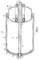
- the figure 1represents a reservoir 10 according to the invention in a first embodiment.
- This reservoir 10is delimited by a wall 12 of generally cylindrical shape.
- Itcomprises a piston 20 adapted to move along an axis 25, this piston thus delimiting, with the wall 12, a chamber 15 of variable volume filled with liquid propellant L at room temperature, of the order of 20 ° C.
- variable volume chamberis leaned against a gas generator 60.
- the reservoir 10comprises a deformable elastomeric membrane 30 pressed against one face of the piston 20 external to the chamber 15.
- This elastomeric membrane 30also seals between the piston 20 and the wall 12.
- the membrane 30is held in the bottom of the tank 10, by annular fixing means 40 which hold the membrane against the wall 12.
- the seal between the axis 25 and the piston 20is achieved by means of a ring seal referenced 54.
- the membrane 30is held by pinching against the outer face of the piston 20 by a washer 56 threaded onto a hub 55 of the piston 20 and held tight by a nut 57.
- the gas generator 60has a cylindrical recess 58 complementary to the hub 55 so that the piston 20 can be pressed against this generator when the reservoir 10 is filled.
- the washer 56is grooved to improve the radial retention of the membrane 30.
- the gas generator 60comprises one or more blocks of powder 50, each block of powder 50 being provided with an initiator 51 able to ignite it.
- this ignitiongenerates a powder gas at a very high temperature, of the order of 1000 ° C., ejected by nozzles 52 in the direction of the membrane 30 and the piston 20.
- the reservoirallows two successive propulsion phases.
- the figure 1represents the state of the tank before the first propulsion phase. In this state, the volume of the chamber 15 is maximum.
- the piston 20is in the retracted position and the deformable membrane 30 matches the shape of the powder compartment 50.
- the figure 2represents the reservoir 10 after the first propulsion phase.
- the volume of the liquid-containing chamber 15has decreased, substantially by one-third in the example described herein, with the piston 20 and the elastomeric membrane 30 moving under the effect of the hot pressurized gas G.
- a part of the liquid L in the chamber 15is entered through an opening 27 of the axis 25 of the piston and is evacuated towards the rear on the figure 2 by a conduit 28 arranged inside this axis.
- the duct 28has a single open end 29, on the opposite side to the opening 27.
- the elastomeric membrane 30provides thermal protection of the walls 12, so that the wall 12 does not heat up.
- the powder gas Gremains hot and therefore under pressure.
- the liquidremains well confined during this first propulsion phase, any displacement of this liquid being, in known manner, detrimental during this phase of ballistics.
- the figure 3represents the reservoir 10 after the second propulsion phase.
- the figure 4represents a reservoir 100 according to the invention in a second embodiment.
- This reservoir 100is almost identical to the reservoir 10 described with reference to Figures 1 to 3 .
- the discharge of the liquidis in the direction of movement of the piston 20.
- the exhaust duct 28has a single open end 29, formed on the side of the opening 27 provided for the entry of the liquid.
- the exhaust duct 28is plugged just behind this opening 27. It comes down to a cavity.
- the tank 100has at its bottom an opening 110 opposite the open end 27 of the duct 28.
- the ring seal 54closes the inlet 27 of the duct 28 when the piston 10 is at the end of the stroke.
- the figure 5represents a reservoir 200 according to the invention in a third embodiment.
- This reservoir 100is almost identical to the tanks 10 and 100 described with reference to Figures 1 to 4 .
Landscapes
- Engineering & Computer Science (AREA)
- Chemical & Material Sciences (AREA)
- Combustion & Propulsion (AREA)
- Mechanical Engineering (AREA)
- General Engineering & Computer Science (AREA)
- Supply Devices, Intensifiers, Converters, And Telemotors (AREA)
Abstract
Description
Translated fromFrenchL'invention concerne un réservoir à piston pressurisé par des gaz chauds.The invention relates to a piston reservoir pressurized by hot gases.
Elle s'applique de façon privilégiée mais non limitative dans le contexte de la pressurisation d'un réservoir d'ergol liquide tel qu'utilisé par exemple dans les missiles tactiques ou stratégiques.It applies in a preferred but non-limiting manner in the context of the pressurization of a liquid propellant tank as used for example in tactical or strategic missiles.
Le document
La chambre comportant le liquide de propulsion est délimitée par une vessie métallique télescopique initialement repliée en accordéon sur elle-même et qui se déplie progressivement sous la poussée du gaz.The chamber comprising the propelling liquid is delimited by a telescopic metal bladder initially folded accordion on itself and unfolds gradually under the thrust of the gas.
Ce mécanisme présente plusieurs inconvénients.This mechanism has several disadvantages.
Tout d'abord, l'agencement télescopique de la vessie est complexe à mettre en oeuvre et ne s'applique qu'aux réservoirs de forme conique.First, the telescopic arrangement of the bladder is complex to implement and only applies to conical tanks.
Par ailleurs, lorsqu'elle se déplie, la vessie ne peut coller au plus près des parois internes du réservoir, si bien qu'une quantité non négligeable de liquide ne peut être expulsée de ce réservoir.Moreover, when it unfolds, the bladder can not stick closer to the inner walls of the tank, so that a significant amount of liquid can be expelled from the tank.
Surtout, ce système à vessie métallique ne peut être utilisé dans un réservoir pressurisé à gaz chauds, la vessie métallique ne jouant aucunement le rôle de barrière thermique. Ceci a deux conséquences : d'une part, la paroi du réservoir s'échauffe et, d'autre part, le gaz se refroidit, sa pression chute. Dans un mécanisme de propulsion à deux phases, il est alors nécessaire de repressuriser le gaz entre les deux phases.Above all, this system with metal bladder can not be used in a pressurized hot gas tank, the metal bladder not playing any role of thermal barrier. This has two consequences: on the one hand, the wall of the tank heats up and, on the other hand, the gas cools down, its pressure drops. In a two-phase propulsion mechanism, it is then necessary to repressurise the gas between the two phases.
La présente invention a pour but principal de pallier aux inconvénients précités en proposant un réservoir comportant :
- une chambre de volume variable, comportant un liquide et délimitée par une paroi ;
- un piston apte à se déplacer dans le réservoir, sous la poussée d'un gaz de poudre à une température largement supérieure à celle du liquide pour diminuer le volume de ladite chambre ; et
- une membrane élastomère déformable plaquée contre une face du piston externe à la chambre, cette membrane étant apte à protéger thermiquement la paroi et à assurer l'étanchéité entre le piston et la paroi.
- a variable volume chamber, comprising a liquid and delimited by a wall;
- a piston adapted to move in the reservoir, under the pressure of a powder gas at a temperature much greater than that of the liquid to reduce the volume of said chamber; and
- a deformable elastomeric membrane pressed against a face of the piston external to the chamber, this membrane being able to thermally protect the wall and to seal between the piston and the wall.
Conformément à l'invention, la membrane est en matière élastomère déformable.According to the invention, the membrane is made of deformable elastomeric material.
La membrane élastomère peut notamment être à base de polymère, par exemple de caoutchouc.The elastomeric membrane may in particular be based on a polymer, for example rubber.
La membrane élastomère remplit trois fonctions simultanément :
- fonction d'étanchéité entre le piston et la paroi;
- barrière thermique visant à empêcher sinon à diminuer fortement l'échauffement de la paroi et le refroidissement du gaz; et
- optimisation du volume de liquide éjecté.
- sealing function between the piston and the wall;
- thermal barrier to prevent or greatly reduce the heating of the wall and the cooling of the gas; and
- optimization of the ejected liquid volume.
Dans un mode particulier de réalisation de l'invention, la membrane élastomère a une épaisseur de l'ordre de 2 ou 3 millimètres. Elle peut ainsi être utilisée dans une application dans laquelle le liquide est à la température ambiante et le gaz propulsion à une température avoisinant 1000°C.In a particular embodiment of the invention, the elastomeric membrane has a thickness of the order of 2 or 3 millimeters. It can thus be used in an application in which the liquid is at ambient temperature and the propulsion gas at a temperature of around 1000 ° C.
Bien entendu, l'épaisseur de la membrane peut varier notamment en fonction de la dimension du réservoir 10, du niveau de pression recherché, de la durée de la mission et du niveau de température.Of course, the thickness of the membrane may vary in particular depending on the size of the
Si le réservoir est utilisé dans un mécanisme de propulsion à deux phases, il n'est pas nécessaire de repressuriser le gaz entre ces phases, du fait de cette barrière thermique.If the tank is used in a two-phase propulsion mechanism, it is not necessary to repressurise the gas between these phases, because of this thermal barrier.
De façon avantageuse, l'invention peut s'appliquer à un réservoir de forme cylindrique.Advantageously, the invention can be applied to a tank of cylindrical shape.
Dans un mode particulier de réalisation de l'invention, le piston se déplace le long d'un axe formant conduit d'évacuation dudit liquide. Le liquide pénètre dans le conduit par une ouverture pratiquée à proximité de l'extrémité du conduit se trouvant au fond de la chambre.In a particular embodiment of the invention, the piston moves along an axis forming the discharge duct of said liquid. The liquid enters the conduit through an opening near the end of the conduit at the bottom of the chamber.
Conformément à l'invention, l'évacuation de liquide peut se faire soit dans le sens de déplacement du piston, soit dans le sens opposé, soit dans les deux sens, cette dernière variante permettant d'alimenter deux systèmes propulsifs disposés de part et d'autre du réservoir.According to the invention, the discharge of liquid can be done either in the direction of movement of the piston, or in the opposite direction, or in both directions, the latter variant for feeding two propulsion systems arranged on both sides. other of the tank.
En conséquence, le conduit d'évacuation comporte au moins une extrémité ouverte pour l'évacuation du liquide, l'extrémité côté fond de chambre étant ouverte pour permettre l'évacuation du liquide dans le sens de déplacement du piston, l'autre extrémité étant ouverte pour une évacuation dans le sens opposé.Accordingly, the exhaust duct has at least one open end for the discharge of the liquid, the chamber end end being open to allow the discharge of the liquid in the direction of movement of the piston, the other end being open for evacuation in the opposite direction.
Lorsque l'évacuation se fait dans le sens de déplacement du piston, une ouverture est pratiquée dans le fond du réservoir pour permettre l'éjection du liquide.When the evacuation is in the direction of displacement of the piston, an opening is made in the bottom of the tank to allow the ejection of the liquid.
D'autres caractéristiques et avantages de la présente invention ressortiront de la description faite ci-dessous, en référence aux dessins annexés qui en illustrent un exemple de réalisation dépourvu de tout caractère limitatif. Sur les figures :
- les
figures 1 à 3 représentent, dans trois états différents, un réservoir selon l'invention dans un premier mode de réalisation ; et - les
figures 4 et5 représentent des réservoirs selon l'invention dans un deuxième et un troisième modes de réalisation.
- the
Figures 1 to 3 represent, in three different states, a reservoir according to the invention in a first embodiment; and - the
figures 4 and5 represent tanks according to the invention in a second and a third embodiment.
La
Ce réservoir 10 est délimité par une paroi 12 de forme générale cylindrique.This
Il comporte un piston 20 apte à se déplacer le long d'un axe 25, ce piston délimitant ainsi, avec la paroi 12, une chambre 15 de volume variable remplie d'ergol liquide L à température ambiante, soit de l'ordre de 20°C.It comprises a
Dans le mode de réalisation décrit ici, la chambre de volume variable est adossée à un générateur de gaz 60.In the embodiment described here, the variable volume chamber is leaned against a
Conformément à l'invention, le réservoir 10 comporte une membrane élastomère déformable 30 plaquée contre une face du piston 20 externe à la chambre 15.According to the invention, the
Cette membrane élastomère 30 assure également l'étanchéité entre le piston 20 et la paroi 12.This
Dans le mode de réalisation décrit ici, la membrane 30 est maintenue dans le fond du réservoir 10, par des moyens de fixation annulaires 40 qui maintiennent la membrane contre la paroi 12.In the embodiment described here, the
L'étanchéité entre l'axe 25 et le piston 20 est réalisée au moyen d'un joint en anneau référencé 54.The seal between the
Dans le mode de réalisation décrit ici, la membrane 30 est maintenue par pincement contre la face externe du piston 20 par une rondelle 56 enfilée sur un moyeu 55 du piston 20 et maintenue serrée par un écrou 57.In the embodiment described here, the
Dans ce mode de réalisation, le générateur de gaz 60 comporte un évidement cylindrique 58 complémentaire du moyeu 55 de sorte que le piston 20 peut être plaqué contre ce générateur lorsque le réservoir 10 est rempli.In this embodiment, the
Dans le mode de réalisation décrit ici, la rondelle 56 est rainurée pour un améliorer le maintien radial de la membrane 30.In the embodiment described here, the
Dans le mode de réalisation décrit ici, le générateur de gaz 60 comporte un ou plusieurs blocs de poudre 50, chaque bloc de poudre 50 étant doté d'un initiateur 51 apte à l'allumer.In the embodiment described here, the
De façon connue, cet allumage génère un gaz de poudre à très haute température, de l'ordre de 1000°C, éjecté par des buses 52 en direction de la membrane 30 et du piston 20.In a known manner, this ignition generates a powder gas at a very high temperature, of the order of 1000 ° C., ejected by
Dans l'exemple décrit ici, le réservoir permet deux phases de propulsion successives.In the example described here, the reservoir allows two successive propulsion phases.
La
En conséquence, le piston 20 est en position reculée et la membrane déformable 30 épouse la forme du compartiment à poudre 50.As a result, the
La
Dans cet état, le volume de la chambre 15 contenant le liquide a diminué, sensiblement d'un tiers dans l'exemple décrit ici, le piston 20 et la membrane élastomère 30 s'étant déplacés sous l'effet du gaz pressurisé chaud G. Sous l'effet de la poussée du piston 20, une partie du liquide L se trouvant dans la chambre 15 est entrée par une ouverture 27 de l'axe 25 du piston et est évacuée, vers l'arrière sur la
La membrane élastomère 30 assure la protection thermique des parois 12, si bien que la paroi 12 ne se réchauffe pas.The
De façon très avantageuse, le gaz de poudre G reste chaud et donc sous pression.Very advantageously, the powder gas G remains hot and therefore under pressure.
De façon avantageuse, le liquide reste bien confiné pendant cette première phase de propulsion, tout déplacement de ce liquide étant, de façon connue, préjudiciable pendant cette phase de balistique.Advantageously, the liquid remains well confined during this first propulsion phase, any displacement of this liquid being, in known manner, detrimental during this phase of ballistics.
La
Dans cet état, le piston 20 vient buter contre l'extrémité du réservoir 10. Du fait que la membrane élastomère 30 colle sensiblement au fond du réservoir 10, l'espace 26 "perdu", c'est-à-dire contenant encore du liquide L après la deuxième phase de propulsion, est excessivement réduit.In this state, the
La
Ce réservoir 100 est quasiment identique au réservoir 10 décrit en référence aux
Mais dans ce mode de réalisation, l'évacuation du liquide se fait dans le sens de déplacement du piston 20.But in this embodiment, the discharge of the liquid is in the direction of movement of the
En conséquence, le conduit d'évacuation 28 comporte une seule extrémité ouverte 29, pratiquée du côté de l'ouverture 27 prévue pour l'entrée du liquide.Accordingly, the
Préférentiellement, le conduit d'évacuation 28 est bouché juste derrière cette ouverture 27. Il se résume à une cavité.Preferably, the
Par ailleurs, le réservoir 100 présente en son fond une ouverture 110 en vis-à-vis de l'extrémité ouverte 27 du conduit 28.Furthermore, the
Dans le mode de réalisation décrit ici, le joint en anneau 54 obture l'entrée 27 du conduit 28 lorsque le piston 10 est en fin de course.In the embodiment described here, the
La
Ce réservoir 100 est quasiment identique aux réservoirs 10 et 100 décrits en référence aux
Mais dans ce mode de réalisation, l'évacuation du liquide se fait dans les deux sens, les deux extrémités 29 du conduit d'évacuation 28 étant ouvertes.But in this embodiment, the discharge of the liquid is in both directions, the two ends 29 of the
Claims (3)
Translated fromFrenchun piston (20) apte à se déplacer dans ledit réservoir (10, 100), sous la poussée d'un gaz de poudre (G) à une température largement supérieure à celle dudit liquide (L) pour diminuer le volume de ladite chambre (15) ;
ledit réservoir (10, 100) étantcaractérisé en ce qu'il comporte une membrane élastomère déformable (30) plaquée contre une face dudit piston (20) externe à ladite chambre (15), ladite membrane (30) étant apte à protéger thermiquement ladite paroi (12) et à assurer l'étanchéité entre ledit piston (20) et ladite paroi (12).
a piston (20) adapted to move in said reservoir (10, 100), under the pressure of a powder gas (G) at a temperature much greater than that of said liquid (L) to reduce the volume of said chamber ( 15);
said tank (10, 100) beingcharacterized in that it comprises a deformable elastomeric membrane (30) pressed against a face of said piston (20) external to said chamber (15), said membrane (30) being able to thermally protect said wall (12) and to seal between said piston (20) and said wall (12).
Applications Claiming Priority (1)
| Application Number | Priority Date | Filing Date | Title |
|---|---|---|---|
| FR0851038AFR2927668B1 (en) | 2008-02-19 | 2008-02-19 | PISTON TANK PRESSURIZED BY HOT GASES. |
Publications (2)
| Publication Number | Publication Date |
|---|---|
| EP2093408A1true EP2093408A1 (en) | 2009-08-26 |
| EP2093408B1 EP2093408B1 (en) | 2018-12-19 |
Family
ID=39829022
Family Applications (1)
| Application Number | Title | Priority Date | Filing Date |
|---|---|---|---|
| EP09152768.9ACeasedEP2093408B1 (en) | 2008-02-19 | 2009-02-13 | Tank |
Country Status (4)
| Country | Link |
|---|---|
| US (1) | US8499983B2 (en) |
| EP (1) | EP2093408B1 (en) |
| CA (1) | CA2654628A1 (en) |
| FR (1) | FR2927668B1 (en) |
Families Citing this family (16)
| Publication number | Priority date | Publication date | Assignee | Title |
|---|---|---|---|---|
| US7905868B2 (en) | 2006-08-23 | 2011-03-15 | Medtronic Minimed, Inc. | Infusion medium delivery device and method with drive device for driving plunger in reservoir |
| US7963954B2 (en) | 2007-04-30 | 2011-06-21 | Medtronic Minimed, Inc. | Automated filling systems and methods |
| US8613725B2 (en)* | 2007-04-30 | 2013-12-24 | Medtronic Minimed, Inc. | Reservoir systems and methods |
| US8434528B2 (en)* | 2007-04-30 | 2013-05-07 | Medtronic Minimed, Inc. | Systems and methods for reservoir filling |
| US8597243B2 (en)* | 2007-04-30 | 2013-12-03 | Medtronic Minimed, Inc. | Systems and methods allowing for reservoir air bubble management |
| JP5102350B2 (en)* | 2007-04-30 | 2012-12-19 | メドトロニック ミニメド インコーポレイテッド | Reservoir filling / bubble management / infusion medium delivery system and method using the system |
| US8079126B2 (en)* | 2008-01-25 | 2011-12-20 | Pratt & Whitney Rocketdyne, Inc. | Friction stir welded bladder fuel tank |
| WO2014051694A2 (en)* | 2012-09-28 | 2014-04-03 | Bp Corporation North America, Inc. | Subsea well containment systems and methods |
| US9353618B2 (en) | 2012-10-31 | 2016-05-31 | Baker Hughes Incorporated | Apparatus and methods for cooling downhole devices |
| KR101616384B1 (en)* | 2014-06-25 | 2016-04-28 | 삼성중공업 주식회사 | Chain Locker Apparatus for Offshore Structure |
| GB2528122A (en)* | 2014-07-11 | 2016-01-13 | Airbus Operations Ltd | Device for mixing and dispensing a sealant or other material |
| US10479532B2 (en)* | 2015-05-07 | 2019-11-19 | Keystone Engineering Company | Stress relieved welds in positive expulsion fuel tanks with rolling metal diaphragms |
| FR3050765B1 (en)* | 2016-04-28 | 2018-04-27 | Safran Helicopter Engines | AUXILIARY SYSTEM FOR DRIVING A TREE OF A PROPELLING SYSTEM OF A HELICOPTER |
| WO2020018565A1 (en) | 2018-07-16 | 2020-01-23 | Moog Inc. | Three-dimensional monolithic diaphragm tank |
| CN113250859A (en)* | 2021-05-27 | 2021-08-13 | 西安航天动力研究所 | Combined piston type liquid propellant storage tank |
| US11707762B2 (en) | 2021-12-21 | 2023-07-25 | Alfons Haar, Inc. | Rotary dispensing tank |
Citations (15)
| Publication number | Priority date | Publication date | Assignee | Title |
|---|---|---|---|---|
| US2970452A (en)* | 1959-04-01 | 1961-02-07 | Union Carbide Corp | Method and apparatus for supplying liquefied gas |
| DE1104267B (en)* | 1959-06-06 | 1961-04-06 | Hans Georg Mebus Dipl Ing | Device for the transportation of liquid fuels in rocket propulsion plants with compressed gas, regardless of location |
| US3494513A (en) | 1966-08-11 | 1970-02-10 | Bell Aerospace Corp | Positive expulsion tank |
| US3592360A (en)* | 1967-06-28 | 1971-07-13 | Arde Inc | Cylindrical fluid storage and expulsion tank |
| DE2136188A1 (en)* | 1971-07-20 | 1973-02-01 | Messerschmitt Boelkow Blohm | COMPRESSED GAS DRAINABLE CONTAINER, IN PARTICULAR FOR LIQUID ROCKET FUEL |
| US3847308A (en)* | 1966-10-10 | 1974-11-12 | Thiokol Chemical Corp | Rolling diaphragm with lateral support |
| US3847309A (en)* | 1966-10-10 | 1974-11-12 | Thiokol Chemical Corp | Rolling diaphragm construction |
| US3847310A (en)* | 1966-12-16 | 1974-11-12 | Thiokol Chemical Corp | Rolling diaphragm for expelling liquid from tapered tanks |
| US3847307A (en)* | 1966-10-10 | 1974-11-12 | Thiokol Chemical Corp | Positive expulsion device for fluids |
| US3895746A (en)* | 1966-08-11 | 1975-07-22 | Textron Inc | Positive expulsion tank |
| US3940032A (en)* | 1966-12-16 | 1976-02-24 | Thiokol Corporation | Rolling diaphragms for expelling liquids |
| US3940031A (en)* | 1966-12-16 | 1976-02-24 | Thiokol Corporation | Reverse acting rolling diaphragm for expelling liquids |
| US3944117A (en)* | 1969-03-26 | 1976-03-16 | The United States Of America As Represented By The Secretary Of The Navy | Rollonet assembly |
| US4538749A (en)* | 1981-07-13 | 1985-09-03 | Rockwell International Corporation | Non-circular rolling diaphragm liquid expulsion apparatus |
| US5407092A (en)* | 1993-09-08 | 1995-04-18 | Trw Inc. | Profiled thickness bonded rolling diaphragm tank |
Family Cites Families (2)
| Publication number | Priority date | Publication date | Assignee | Title |
|---|---|---|---|---|
| US3156100A (en)* | 1961-05-19 | 1964-11-10 | Union Carbide Corp | Apparatus for supplying liquefied gas |
| US5167631A (en)* | 1991-09-17 | 1992-12-01 | Imed Corporation | Portable infusion device |
- 2008
- 2008-02-19FRFR0851038Apatent/FR2927668B1/ennot_activeExpired - Fee Related
- 2009
- 2009-02-13EPEP09152768.9Apatent/EP2093408B1/ennot_activeCeased
- 2009-02-18USUS12/388,220patent/US8499983B2/ennot_activeExpired - Fee Related
- 2009-02-18CACA002654628Apatent/CA2654628A1/ennot_activeAbandoned
Patent Citations (15)
| Publication number | Priority date | Publication date | Assignee | Title |
|---|---|---|---|---|
| US2970452A (en)* | 1959-04-01 | 1961-02-07 | Union Carbide Corp | Method and apparatus for supplying liquefied gas |
| DE1104267B (en)* | 1959-06-06 | 1961-04-06 | Hans Georg Mebus Dipl Ing | Device for the transportation of liquid fuels in rocket propulsion plants with compressed gas, regardless of location |
| US3494513A (en) | 1966-08-11 | 1970-02-10 | Bell Aerospace Corp | Positive expulsion tank |
| US3895746A (en)* | 1966-08-11 | 1975-07-22 | Textron Inc | Positive expulsion tank |
| US3847309A (en)* | 1966-10-10 | 1974-11-12 | Thiokol Chemical Corp | Rolling diaphragm construction |
| US3847308A (en)* | 1966-10-10 | 1974-11-12 | Thiokol Chemical Corp | Rolling diaphragm with lateral support |
| US3847307A (en)* | 1966-10-10 | 1974-11-12 | Thiokol Chemical Corp | Positive expulsion device for fluids |
| US3847310A (en)* | 1966-12-16 | 1974-11-12 | Thiokol Chemical Corp | Rolling diaphragm for expelling liquid from tapered tanks |
| US3940032A (en)* | 1966-12-16 | 1976-02-24 | Thiokol Corporation | Rolling diaphragms for expelling liquids |
| US3940031A (en)* | 1966-12-16 | 1976-02-24 | Thiokol Corporation | Reverse acting rolling diaphragm for expelling liquids |
| US3592360A (en)* | 1967-06-28 | 1971-07-13 | Arde Inc | Cylindrical fluid storage and expulsion tank |
| US3944117A (en)* | 1969-03-26 | 1976-03-16 | The United States Of America As Represented By The Secretary Of The Navy | Rollonet assembly |
| DE2136188A1 (en)* | 1971-07-20 | 1973-02-01 | Messerschmitt Boelkow Blohm | COMPRESSED GAS DRAINABLE CONTAINER, IN PARTICULAR FOR LIQUID ROCKET FUEL |
| US4538749A (en)* | 1981-07-13 | 1985-09-03 | Rockwell International Corporation | Non-circular rolling diaphragm liquid expulsion apparatus |
| US5407092A (en)* | 1993-09-08 | 1995-04-18 | Trw Inc. | Profiled thickness bonded rolling diaphragm tank |
Also Published As
| Publication number | Publication date |
|---|---|
| CA2654628A1 (en) | 2009-08-19 |
| FR2927668A1 (en) | 2009-08-21 |
| US8499983B2 (en) | 2013-08-06 |
| US20090206111A1 (en) | 2009-08-20 |
| EP2093408B1 (en) | 2018-12-19 |
| FR2927668B1 (en) | 2017-10-06 |
Similar Documents
| Publication | Publication Date | Title |
|---|---|---|
| EP2093408B1 (en) | Tank | |
| EP2683449B1 (en) | Device for extinguishing a fire | |
| EP0660066B1 (en) | Dispersable countermass for recoilless weapons | |
| CA2661695A1 (en) | Liquid propulsion device incorporating a pyrotechnic gas generator in the structure thereof | |
| EP1496268B1 (en) | Pyrotechnical actuator with variable thrust | |
| EP3234332B1 (en) | Device for modulating a gas ejection section | |
| CA2912652C (en) | Pyrotechnic gas generator for actuating a jack | |
| FR2922006A1 (en) | GAS GENERATOR HAVING DIFFUSION CHAMBER PROVIDED WITH INTERNAL CONDUIT | |
| EP3313536B1 (en) | Fire extinguisher | |
| FR2569234A1 (en) | Multiple chamber rocket engine | |
| EP1637511B1 (en) | Pyrotechnical actuator with a charge comprising an oxidizer and a dissociated reducing agent | |
| EP0211703B1 (en) | Plug for a solid propellant with two combustion chambers | |
| FR2901523A1 (en) | Pyrotechnic gas generator for motor vehicle, has pipe completely isolating tranquillization chamber from combustion chamber and transfer chamber in end position, and opens passage for gas in another end position | |
| EP2964947B1 (en) | Device for modulating a gas ejection section | |
| FR2936715A1 (en) | Fluid ejecting device e.g. hydraulic oil extinguisher, for aircraft, has pressurization chamber provided with sock sealingly separating interior of pressurization chamber from side walls of tank | |
| EP3325795B1 (en) | Device for modifying gas ejection section | |
| EP4389236B1 (en) | Curved fire extinguisher for an engine | |
| EP1802871B1 (en) | Pyrotechnic actuator with controllable force and optimised geometry | |
| FR2927417A1 (en) | OBUS OF DISPERSION OF PROJECTILES | |
| FR2724979A1 (en) | Exhaust nozzle firing guide for sea-launched missile | |
| EP0661513A1 (en) | Projectile propulsion assembly | |
| WO2024047320A1 (en) | Self-eating hybrid rocket engine | |
| FR3038891A1 (en) | DEVICE FOR DISTRIBUTING A MATERIAL | |
| FR2897114A1 (en) | Internal ignition device for internal burning propellant grain, has temporary walls sealed by covers that are ejectable under effect of combustion product gas upstream walls, after ignition of secondary igniter |
Legal Events
| Date | Code | Title | Description |
|---|---|---|---|
| PUAI | Public reference made under article 153(3) epc to a published international application that has entered the european phase | Free format text:ORIGINAL CODE: 0009012 | |
| 17P | Request for examination filed | Effective date:20090213 | |
| AK | Designated contracting states | Kind code of ref document:A1 Designated state(s):AT BE BG CH CY CZ DE DK EE ES FI FR GB GR HR HU IE IS IT LI LT LU LV MC MK MT NL NO PL PT RO SE SI SK TR | |
| AX | Request for extension of the european patent | Extension state:AL BA RS | |
| 17Q | First examination report despatched | Effective date:20091117 | |
| AKX | Designation fees paid | Designated state(s):DE ES FR GB IT SE | |
| GRAP | Despatch of communication of intention to grant a patent | Free format text:ORIGINAL CODE: EPIDOSNIGR1 | |
| INTG | Intention to grant announced | Effective date:20180508 | |
| GRAJ | Information related to disapproval of communication of intention to grant by the applicant or resumption of examination proceedings by the epo deleted | Free format text:ORIGINAL CODE: EPIDOSDIGR1 | |
| RAP1 | Party data changed (applicant data changed or rights of an application transferred) | Owner name:SAFRAN AIRCRAFT ENGINES | |
| GRAP | Despatch of communication of intention to grant a patent | Free format text:ORIGINAL CODE: EPIDOSNIGR1 | |
| INTC | Intention to grant announced (deleted) | ||
| RAP1 | Party data changed (applicant data changed or rights of an application transferred) | Owner name:ARIANEGROUP SAS | |
| INTG | Intention to grant announced | Effective date:20180725 | |
| GRAS | Grant fee paid | Free format text:ORIGINAL CODE: EPIDOSNIGR3 | |
| GRAA | (expected) grant | Free format text:ORIGINAL CODE: 0009210 | |
| AK | Designated contracting states | Kind code of ref document:B1 Designated state(s):DE ES FR GB IT SE | |
| REG | Reference to a national code | Ref country code:GB Ref legal event code:FG4D Free format text:NOT ENGLISH | |
| REG | Reference to a national code | Ref country code:DE Ref legal event code:R096 Ref document number:602009056240 Country of ref document:DE | |
| PGFP | Annual fee paid to national office [announced via postgrant information from national office to epo] | Ref country code:DE Payment date:20190312 Year of fee payment:11 Ref country code:GB Payment date:20190320 Year of fee payment:11 | |
| PG25 | Lapsed in a contracting state [announced via postgrant information from national office to epo] | Ref country code:SE Free format text:LAPSE BECAUSE OF FAILURE TO SUBMIT A TRANSLATION OF THE DESCRIPTION OR TO PAY THE FEE WITHIN THE PRESCRIBED TIME-LIMIT Effective date:20181219 | |
| PGFP | Annual fee paid to national office [announced via postgrant information from national office to epo] | Ref country code:FR Payment date:20190221 Year of fee payment:11 | |
| PG25 | Lapsed in a contracting state [announced via postgrant information from national office to epo] | Ref country code:IT Free format text:LAPSE BECAUSE OF FAILURE TO SUBMIT A TRANSLATION OF THE DESCRIPTION OR TO PAY THE FEE WITHIN THE PRESCRIBED TIME-LIMIT Effective date:20181219 Ref country code:ES Free format text:LAPSE BECAUSE OF FAILURE TO SUBMIT A TRANSLATION OF THE DESCRIPTION OR TO PAY THE FEE WITHIN THE PRESCRIBED TIME-LIMIT Effective date:20181219 | |
| REG | Reference to a national code | Ref country code:DE Ref legal event code:R097 Ref document number:602009056240 Country of ref document:DE | |
| PLBE | No opposition filed within time limit | Free format text:ORIGINAL CODE: 0009261 | |
| STAA | Information on the status of an ep patent application or granted ep patent | Free format text:STATUS: NO OPPOSITION FILED WITHIN TIME LIMIT | |
| 26N | No opposition filed | Effective date:20190920 | |
| REG | Reference to a national code | Ref country code:DE Ref legal event code:R119 Ref document number:602009056240 Country of ref document:DE | |
| GBPC | Gb: european patent ceased through non-payment of renewal fee | Effective date:20200213 | |
| PG25 | Lapsed in a contracting state [announced via postgrant information from national office to epo] | Ref country code:DE Free format text:LAPSE BECAUSE OF NON-PAYMENT OF DUE FEES Effective date:20200901 Ref country code:FR Free format text:LAPSE BECAUSE OF NON-PAYMENT OF DUE FEES Effective date:20200229 Ref country code:GB Free format text:LAPSE BECAUSE OF NON-PAYMENT OF DUE FEES Effective date:20200213 |