EP2092898A2 - Surgical stapling apparatus with reprocessible handle assembly - Google Patents
Surgical stapling apparatus with reprocessible handle assemblyDownload PDFInfo
- Publication number
- EP2092898A2 EP2092898A2EP09250399AEP09250399AEP2092898A2EP 2092898 A2EP2092898 A2EP 2092898A2EP 09250399 AEP09250399 AEP 09250399AEP 09250399 AEP09250399 AEP 09250399AEP 2092898 A2EP2092898 A2EP 2092898A2
- Authority
- EP
- European Patent Office
- Prior art keywords
- assembly
- articulation
- handle
- firing
- control rod
- Prior art date
- Legal status (The legal status is an assumption and is not a legal conclusion. Google has not performed a legal analysis and makes no representation as to the accuracy of the status listed.)
- Granted
Links
Images


Classifications
- A—HUMAN NECESSITIES
- A61—MEDICAL OR VETERINARY SCIENCE; HYGIENE
- A61B—DIAGNOSIS; SURGERY; IDENTIFICATION
- A61B17/00—Surgical instruments, devices or methods
- A61B17/068—Surgical staplers, e.g. containing multiple staples or clamps
- A61B17/072—Surgical staplers, e.g. containing multiple staples or clamps for applying a row of staples in a single action, e.g. the staples being applied simultaneously
- A61B17/07207—Surgical staplers, e.g. containing multiple staples or clamps for applying a row of staples in a single action, e.g. the staples being applied simultaneously the staples being applied sequentially
- A—HUMAN NECESSITIES
- A61—MEDICAL OR VETERINARY SCIENCE; HYGIENE
- A61B—DIAGNOSIS; SURGERY; IDENTIFICATION
- A61B17/00—Surgical instruments, devices or methods
- A61B2017/0046—Surgical instruments, devices or methods with a releasable handle; with handle and operating part separable
- A61B2017/00473—Distal part, e.g. tip or head
- A—HUMAN NECESSITIES
- A61—MEDICAL OR VETERINARY SCIENCE; HYGIENE
- A61B—DIAGNOSIS; SURGERY; IDENTIFICATION
- A61B17/00—Surgical instruments, devices or methods
- A61B17/28—Surgical forceps
- A61B17/29—Forceps for use in minimally invasive surgery
- A61B2017/2901—Details of shaft
- A—HUMAN NECESSITIES
- A61—MEDICAL OR VETERINARY SCIENCE; HYGIENE
- A61B—DIAGNOSIS; SURGERY; IDENTIFICATION
- A61B17/00—Surgical instruments, devices or methods
- A61B17/28—Surgical forceps
- A61B17/29—Forceps for use in minimally invasive surgery
- A61B2017/2901—Details of shaft
- A61B2017/2905—Details of shaft flexible
- A—HUMAN NECESSITIES
- A61—MEDICAL OR VETERINARY SCIENCE; HYGIENE
- A61B—DIAGNOSIS; SURGERY; IDENTIFICATION
- A61B17/00—Surgical instruments, devices or methods
- A61B17/28—Surgical forceps
- A61B17/29—Forceps for use in minimally invasive surgery
- A61B2017/2901—Details of shaft
- A61B2017/2906—Multiple forceps
- A—HUMAN NECESSITIES
- A61—MEDICAL OR VETERINARY SCIENCE; HYGIENE
- A61B—DIAGNOSIS; SURGERY; IDENTIFICATION
- A61B17/00—Surgical instruments, devices or methods
- A61B17/28—Surgical forceps
- A61B17/29—Forceps for use in minimally invasive surgery
- A61B17/2909—Handles
- A61B2017/291—Handles the position of the handle being adjustable with respect to the shaft
- A—HUMAN NECESSITIES
- A61—MEDICAL OR VETERINARY SCIENCE; HYGIENE
- A61B—DIAGNOSIS; SURGERY; IDENTIFICATION
- A61B17/00—Surgical instruments, devices or methods
- A61B17/28—Surgical forceps
- A61B17/29—Forceps for use in minimally invasive surgery
- A61B17/2909—Handles
- A61B2017/2912—Handles transmission of forces to actuating rod or piston
- A61B2017/2923—Toothed members, e.g. rack and pinion
- A—HUMAN NECESSITIES
- A61—MEDICAL OR VETERINARY SCIENCE; HYGIENE
- A61B—DIAGNOSIS; SURGERY; IDENTIFICATION
- A61B17/00—Surgical instruments, devices or methods
- A61B17/28—Surgical forceps
- A61B17/29—Forceps for use in minimally invasive surgery
- A61B17/2909—Handles
- A61B2017/2925—Pistol grips
- A—HUMAN NECESSITIES
- A61—MEDICAL OR VETERINARY SCIENCE; HYGIENE
- A61B—DIAGNOSIS; SURGERY; IDENTIFICATION
- A61B17/00—Surgical instruments, devices or methods
- A61B17/28—Surgical forceps
- A61B17/29—Forceps for use in minimally invasive surgery
- A61B2017/2926—Details of heads or jaws
- A61B2017/2927—Details of heads or jaws the angular position of the head being adjustable with respect to the shaft
- A—HUMAN NECESSITIES
- A61—MEDICAL OR VETERINARY SCIENCE; HYGIENE
- A61B—DIAGNOSIS; SURGERY; IDENTIFICATION
- A61B90/00—Instruments, implements or accessories specially adapted for surgery or diagnosis and not covered by any of the groups A61B1/00 - A61B50/00, e.g. for luxation treatment or for protecting wound edges
- A61B90/08—Accessories or related features not otherwise provided for
- A61B2090/0813—Accessories designed for easy sterilising, i.e. re-usable
- A—HUMAN NECESSITIES
- A61—MEDICAL OR VETERINARY SCIENCE; HYGIENE
- A61B—DIAGNOSIS; SURGERY; IDENTIFICATION
- A61B90/00—Instruments, implements or accessories specially adapted for surgery or diagnosis and not covered by any of the groups A61B1/00 - A61B50/00, e.g. for luxation treatment or for protecting wound edges
- A61B90/70—Cleaning devices specially adapted for surgical instruments
Definitions
- the present inventionrelates in general to endoscopic surgical instruments including, but not limited to, surgical stapler instruments that have disposable loading units that are capable of applying lines of staples to tissue while cutting the tissue between those staple lines and, more particularly, to improvements relating to such instruments.
- Endoscopic surgical instrumentsare often preferred over traditional open surgical devices since a smaller incision tends to reduce the post-operative recovery time and complications. Consequently, significant development has gone into a range of endoscopic surgical instruments that are suitable for precise placement of a distal end effector at a desired surgical site through a cannula of a trocar. These distal end effectors engage the tissue in a number of ways to achieve a diagnostic or therapeutic effect (e.g., endocutter, grasper, cutter, staplers, clip applier, access device, drug/gene therapy delivery device, and energy device using ultrasound, RF, laser, etc.).
- a diagnostic or therapeutic effecte.g., endocutter, grasper, cutter, staplers, clip applier, access device, drug/gene therapy delivery device, and energy device using ultrasound, RF, laser, etc.
- Known surgical staplersinclude an end effector that simultaneously makes a longitudinal incision in tissue and applies lines of staples on opposing sides of the incision.
- the end effectorincludes a pair of cooperating jaw members that, if the instrument is intended for endoscopic or laparoscopic applications, are capable of passing through a cannula passageway.
- One of the jaw membersreceives a staple cartridge having at least two laterally spaced rows of staples.
- the other jaw memberdefines an anvil having staple-forming pockets aligned with the rows of staples in the cartridge.
- the instrumentcommonly includes a plurality of reciprocating wedges which, when driven distally, pass through openings in the staple cartridge and engage drivers supporting the staples to effect the firing of the staples toward the anvil.
- one type of surgical stapleremploys a staple cartridge.
- the staple cartridgetypically supports a plurality of staples oriented on both sides of a longitudinally extending slot in the cartridge body that is adapted to receive a cutting member that is driven longitudinally therethrough. As the cutting member is driven through the cartridge slot, the staples are driven upward into the anvil portion of the instrument.
- the cutting membermay be supported on a driven member that comprises a portion of the instrument apart from the cartridge. Examples of those types of devices are described in U.S. Pat. No. 6,905,057 to Jeffrey S. Swayze and Frederick E.
- DLUdisposable loading units
- Such devicesthat are designed to accommodate DLU's purport to offer the advantage of a "fresh" knife blade for each firing of the instrument.
- An example of such surgical stapling instrument and DLU arrangementis disclosed in U.S. Patent No, 5,865,361 to Milliman et al. , the disclosure of which is herein incorporated by reference in its entirety.
- Such disposable loading unitsare sterilized and packaged in sterile packaging materials prior to use.
- the surgical stapling instrumentis also sterilized prior to use. After the disposable loading unit is used, it is discarded. While the prior surgical stapling instruments could also conceivably be re-sterilized for additional uses, those prior instruments such as those described in the aforementioned U.S. Patent No. 5,865,361 and other known instruments adapted for use with disposable loading units are not well-suited for easy disassembly to facilitate sterilization of their various internal components. Consequently, such units are often disposed of after a single use.
- a reusable surgical stapling apparatusmay include a first handle segment and a second handle segment that is detachably coupled to the first handle segment to form a handle housing.
- a firing assemblymay be removably supported in the handle housing as a lift out removable unit.
- the firing assemblymay comprise a movable handle and an actuation shaft that is mounted for longitudinal movement in response to manipulation of the movable handle.
- the surgical stapling apparatusmay further include a control rod assembly that has a proximal end that is configured to removably interface with the firing assembly.
- the control rod assemblymay protrude outward from the handle housing and may have a distal end that is configured to be operably attached to a disposable loading unit.
- a reusable surgical stapling apparatusmay include a first handle segment and a second handle segment that is detachably coupled to the first handle segment by at least one quick disconnect fastener to form a handle housing.
- the apparatusmay further include a firing assembly that is sized to be removably supported within the handle housing and removed therefrom as a unit.
- the firing assemblymay comprise an internal frame assembly that has a movable handle operably coupled thereto.
- An actuation shaftmay be mounted for longitudinal movement within the internal frame assembly.
- the actuation shaftmay be longitudinally movable in a distal direction in response to manipulation of the movable handle and may also be movable in a proximal direction in response to a retraction motion applied thereto.
- the apparatusmay further include a retraction mechanism that is coupled to the actuation shaft for selectively applying the retraction motion to the actuation shaft.
- Various embodimentalso include a control rod assembly that has a proximal end that is configured to removably interface with the firing assembly.
- the control rod assemblymay protrude outward from the handle housing and may have a distal end that is configured to be operably attached to a disposable loading unit.
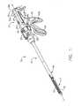
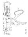
- FIG. 1is a perspective view of a reusable surgical stapling apparatus of various embodiments of the present invention with an articulatable disposable loading unit coupled thereto.
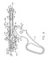
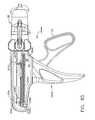
- FIG. 2is a perspective view of a reusable surgical stapling apparatus of various embodiments of the present invention with a non-articulatable disposable loading unit coupled thereto.
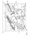
- FIG. 3is a partial exploded perspective view of a quick disconnect fastener embodiment of the present invention.
- FIG. 4is an exploded assembly view of a reusable surgical stapling apparatus of various embodiments of the present invention.
- FIG. 5is another exploded assembly view of the reusable surgical stapling apparatus of FIG. 4 .
- FIG. 6is an exploded assembly view of a portion of a handle assembly of the reusable surgical stapling apparatus embodiment of FIGS. 4 and 5 .
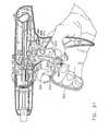
- FIG. 7is a partial right side perspective view of a firing assembly embodiment of the present invention.
- FIG. 8is a partial left side perspective view of the firing assembly embodiment of FIG. 7 .
- FIG. 9is a left side view of the firing assembly embodiment of FIGS. 7 and 8 .
- FIG. 10is an exploded assembly view of a control rod assembly embodiment of various embodiments of the present invention.
- FIG. 11is an exploded assembly view of a rotation knob assembly and articulation mechanism embodiment of the present invention.
- FIG. 12is a perspective view of a contaminated reusable surgical stapling apparatus of FIGS. 1 and 2 with the disposable loading unit detached therefrom.
- FIG. 13is a perspective view of the contaminated reusable surgical stapling apparatus of FIG. 12 with the control rod extended out of the distal end of the elongated body.
- FIG. 14is a diagrammatic representation of a collection of actions of a cleaning method embodiment of the present invention.
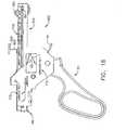
- FIG. 15is a perspective view depicting the submersion of the extended control rod into a cleaning solution.
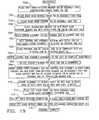
- FIG. 16is another diagrammatic representation of a collection of other actions of a cleaning method embodiment of the present invention.
- FIG. 17is a perspective view depicting the submersion of various components of an embodiment of the present invention in a cleaning solution.
- FIG. 18is a side view of a firing assembly embodiment of various embodiments of the present invention.
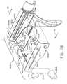
- FIG. 19is a diagrammatic representation of a collection of actions of a reassembly method embodiment of the present invention.
- FIG. 20is an exploded view depicting use of an assembly tray of an embodiment of the present invention.
- FIG. 21is a perspective view of another surgical stapling apparatus of an embodiment of the present invention attached to a non-articulatable disposable loading unit.
- FIG. 22is an exploded assembly view of a handle assembly of the surgical stapling apparatus depicted in FIG. 21 .
- FIG. 23is an exploded assembly view of another disposable loading unit sensing mechanism embodiment of various embodiments of the present invention.
- FIG. 24is an exploded assembly view of another rotation knob assembly and articulation mechanism embodiment of the present invention.
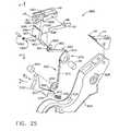
- FIG. 25is an exploded assembly view of a firing release trigger assembly of an embodiment of the present invention.
- FIG. 26is a partial assembly view of the firing release trigger assembly depicted in FIG. 25 .
- FIG. 27is an assembly view of a handle assembly embodiment of the present invention.
- FIG. 28is another assembly view of a handle assembly embodiment of the present invention with the movable handle thereof pulled against the stationary handle portion to close the anvil on the disposable loading unit.
- FIG. 29is another assembly view of a handle assembly embodiment of the present invention with the movable handle returned to a starting position after the anvil has been closed.
- FIG. 30is another assembly view of a handle assembly embodiment of the present invention prior to activating the firing release trigger.
- FIG. 31is another assembly view of a handle assembly embodiment of the present invention with the firing release trigger activated.
- FIG. 32is another assembly view of a handle assembly embodiment of the present invention with the firing release trigger activated and the movable handle starting to be actuated.
- FIG. 33another assembly view of a handle assembly embodiment of the present invention with the firing release trigger activated with the movable handle thereof pulled against the stationary handle portion.
- FIG. 34is a partial assembly view of another firing release trigger embodiment of the present invention.
- FIG. 35is a perspective view of another surgical stapling apparatus embodiment of the present invention.
- FIG. 36is a partial exploded assembly view of a portion of the handle assembly and rotatable shroud of the surgical stapling apparatus of FIG. 35 .
- FIG. 37is a perspective view of a portion of the surgical stapling apparatus embodiment of FIGS. 35 and 36 with a portion of the handle housing removed to show the various components therein in the rotation mode.
- FIG. 38is a side view of the portion of the surgical stapling apparatus embodiment depicted in FIG. 36 with the selector switch thereof in a distal unlocked position.
- FIG. 39is an enlarged view of the bolt disengaged from the rotation lock ring when the apparatus is in the rotation mode.
- FIG. 40is a cross-sectional view of the surgical stapling apparatus taken along line 40-40 in FIG. 38 .
- FIG. 41is a partial top view of the surgical stapling apparatus of FIGS. 35-40 with the grip portion shown in cross-section.
- FIG. 42is a perspective view of a portion of the surgical stapling apparatus embodiment of FIGS. 35-41 with a portion of the handle housing removed to show the various components therein in the articulation mode.
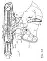
- FIG. 43is a side view of the portion of the surgical stapling apparatus embodiment depicted in FIG. 36 with the selector switch thereof in a proximal locked position.
- FIG. 44is an enlarged view of the bolt engaging the rotation lock ring to lock the apparatus in the articulation mode.
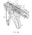
- FIG. 45is a partial cross-sectional view of the surgical stapling apparatus of FIG. 43 taken along line 45-45 in FIG. 43 .
- FIG. 46is a partial cross-sectional view of a handle assembly of a surgical stapling apparatus of the present invention employing an alternate translation member.
- FIG. 47is a perspective view of another surgical stapling apparatus embodiment of the present invention.
- FIG. 48is an enlarged perspective view of the handle assembly portion of the surgical stapling instrument of FIG. 47 with a portion of the handle housing removed for clarity.
- FIG. 49is partial side view of the handle assembly depicted in FIG. 49 with a portion of the handle housing removed for clarity.
- FIG. 50is a partial top view of the handle assembly depicted in FIG. 49 with some components shown in cross-section and with the articulation system thereof in a locked position.
- FIG. 51is a partial top view of the handle assembly depicted in FIGS. 49 and 50 with some components shown in cross-section and with the articulation system thereof in an unlocked position.
- FIG. 52is a perspective view of another surgical stapling apparatus embodiment of the present invention.
- FIG. 53is a perspective assembly view of the handle assembly portion of the surgical stapling apparatus of FIG. 52 with a portion of the handle housing removed and the sensor cylinder omitted for clarity.
- FIG. 54is a left-side perspective assembly view of a portion of the handle assembly of the surgical stapling apparatus of FIGS. 52 and 53 with the housing removed for clarity.
- FIG. 55is a right-side perspective assembly view of a portion of the handle assembly of the surgical stapling apparatus of FIGS. 52-54 with the housing removed for clarity.
- FIG. 56is a side view of a portion of the articulation system, gear and articulation selector switch embodiments with the articulation switch in a neutral position.
- FIG. 57is another side view of the articulation system, gear and articulation selector switch embodiments with the articulation switch in the left articulation position.
- FIG. 58is another side view of the articulation system and gear and articulation selector switch embodiments with the articulation switch in the right articulation position.
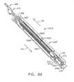
- FIG. 59is a bottom view of the gear selector switch, drive gear assembly, articulation transfer gear train and actuation bar of an embodiment of the present invention with the selector gear selector switch in the articulation position.
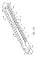
- FIG. 60is a bottom view of the gear selector switch, drive gear assembly, articulation transfer gear train and actuation bar of an embodiment of the present invention with the selector gear selector switch in the firing position.
- FIG. 61is an enlarged view of the gear selector switch embodiment in the articulation position.
- FIG. 62is a cross-sectional view of the gear selector switch embodiment in the firing position.
- FIG. 63is an end view of a various components of the surgical stapling apparatus in an articulation mode.
- FIG. 64is another end view of the components depicted in FIG. 63 in a firing mode.
- FIG. 65is a partial cross-sectional perspective view of an alternative articulation mechanism embodiment of the present invention.
- FIG. 66is a partial top cross-sectional view of the articulation mechanism of FIG. 65 .
- FIG. 67illustrates a position of the cam disc and articulation pin of the articulation mechanism embodiment of FIGS. 65 and 66 in a left articulated position.
- FIG. 68illustrates a position of the cam disc and articulation pin of the articulation mechanism embodiment of FIGS. 65 and 66 in a straight (non-articulated) position.
- FIG. 69illustrates a position of the cam disc and articulation pin of the articulation mechanism embodiment of FIGS. 65 and 66 in a right articulated position.
- FIG. 70is a cross-sectional plan view of a portion of another articulation mechanism embodiment of the present invention.
- FIG. 71is a partial cross-sectional view of a portion of the articulation mechanism embodiment of FIG. 70 .
- FIG. 72is a side view of another articulation mechanism embodiment of the present invention with some of the components thereof shown in cross-section.
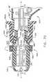
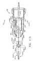
- FIG. 73is a cross-sectional view of the articulation mechanism embodiment of FIG. 72 taken along line 73-73 in FIG. 72 .
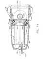
- FIG. 74is a side view of another articulation mechanism embodiment of the present invention with some of the components thereof shown in cross-section.
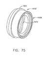
- FIG. 75is a perspective view of an outer articulation ring embodiment of the articulation mechanism of FIG. 74 .
- FIG. 76is a left side perspective view of another surgical stapling apparatus embodiment of the present invention.
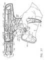
- FIG. 77is a right side perspective view of the surgical stapling apparatus embodiment depicted in FIG. 76 .
- FIG. 78is an exploded assembly view of the right housing segment of the handle assembly with the removable cover detached from the housing segment.
- FIG. 79is another view of the right housing segment of the handle assembly with the removable cover detached from the housing segment.
- FIG. 80is a right side view of the handle assembly of the surgical stapling apparatus depicted in FIGS. 76-78 .
- FIG. 81is a cross-sectional view of the housing assembly taken along line 81-81 in FIG. 80 .
- FIG. 82is a cross-sectional view of the housing assembly taken along line 82-82 in FIG. 80 .
- FIG. 83is a cross-sectional view of a portion of the housing assembly and cocking knob taken along line 83-83 in FIG. 80 .
- FIG. 84is a right side view of the handle assembly of the surgical stapling apparatus depicted in FIGS. 76-83 with the removable cover removed to show the retract knob and the cocking knob in the "pre-fired" position.
- FIG. 85is another right side view of the handle assembly of FIG. 84 with the cocking knob in a cocked position.
- FIG. 86is another right side view of the handle assembly of FIGS. 84 and 85 showing the position of the retract knob and the cocking knob prior to reaching the fully fired position.
- FIG. 87is a partial cross-sectional view of the handle assembly and cocking knob with the cocking knob biased in a clockwise direction to release the lock member.
- FIG. 88is another partial cross-sectional view of the handle assembly, cocking knob and retract knob wherein the retract knob has released the lock member to permit the actuation shaft to be automatically retracted.
- FIG. 89is a partial perspective view of a portion of a disposable loading unit of various embodiments of the present invention.
- FIG. 90is a perspective view of a pawl embodiment of various embodiments of the present invention.
- FIG. 91is a perspective view of another pawl embodiment of various embodiments of the present invention.
- FIG. 92is a bottom perspective view of an actuation shaft embodiment of various embodiments of the present invention.
- FIG. 93is a bottom perspective view of another actuation shaft embodiment of various embodiments of the present invention.
- FIG. 93Ais a side view of a portion of a firing system embodiment of the present invention used in connection with a surgical stapling instrument of the type disclosed in U.S. Patent Application Serial No. 11/821,277 with the tooth in driving engagement with the firing member.
- FIG. 93Bis another side view of the firing system embodiment of FIG. 93A with the tooth in the disengaged position.
- FIG. 94is a perspective view of a surgical stapling apparatus and a disposable loading unit embodiment of the present invention.
- FIG. 95is a perspective view of the disposable loading unit embodiment depicted in FIG. 94 .
- FIG. 96is an exploded assembly view of the disposable loading unit embodiment of FIG. 95 .
- FIG. 97is a perspective view of the disposable loading unit of FIGS. 95 and 96 being articulated with a pair of surgical graspers.
- FIG. 98is a perspective view of another disposable loading unit embodiment of the present invention.
- FIG. 99is an exploded assembly view of the disposable loading unit embodiment of FIG. 98 .
- FIG. 100is a perspective view of the disposable loading unit of FIGS. 98 and 99 being articulated with a pair of surgical graspers.
- FIG. 101is a perspective view of the disposable loading unit of FIGS. 98-100 illustrating passive articulation travel and active articulation travel thereof.
- FIG. 102is a perspective view of another disposable loading unit embodiment of the present invention.
- FIG. 103is an exploded assembly view of the disposable loading unit embodiment of FIG. 102 .
- FIG. 104is an exploded assembly view of another disposable loading unit sensing mechanism and control rod assembly embodiment of various embodiments of the present invention.
- FIG. 105is a perspective view of another disposable loading unit embodiment of the present invention illustrating passive articulation travel and active articulation travel thereof.
- FIG. 106is an exploded assembly view of the disposable loading unit of FIG. 105 .
- FIG. 107is a proximal end view of the disposable loading unit of FIGS. 105 and 106 taken in the direction represented by arrows 107-107 in FIG. 105 .
- FIG. 108is a perspective view of another surgical stapling apparatus embodiment of the present invention.
- FIG. 109is an exploded assembly view of an articulation system embodiment of the present invention employed in the surgical stapling apparatus of FIG. 108 .
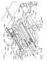
- FIG 110is an exploded assembly view of portions of the intermediate articulation joint of the articulation system of FIG. 109 .
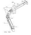
- FIG. 111is a perspective of the surgical stapling apparatus of FIG. 108 employed in an open surgical application.
- FIG. 112is a perspective view of another surgical stapling apparatus embodiment of the present invention employed in connection with a conventional trocar to perform an endoscopic surgical procedure.
- FIG. 113is a perspective view of another articulation system embodiment of the present invention.
- FIG. 114is a partial exploded assembly view of the articulation system of FIG. 113 .
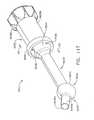
- FIG. 115is a side assembly view of the articulation system of FIGS. 113 and 114 .
- FIG. 116is a perspective view of another articulation system embodiment of the present invention.
- FIG. 117is a perspective view of another articulation system embodiment of the present invention.
- FIG. 118is an exploded assembly view of the articulation system of FIG. 117 .
- FIG. 119is a side assembly view of a portion of the articulation system of FIGS. 117 and 118 with some components thereof shown in cross-section for clarity.
- FIG. 120is a partial perspective assembly view of various articulation bar and pin embodiments of the present invention.
- FIG. 121is a cross-sectional view of the articulation bar and pin embodiments depicted in FIG. 120 .
- FIG. 122is a perspective view of another surgical stapling apparatus embodiment of the present invention employed in connection with a conventional trocar to perform an endoscopic surgical procedure.
- FIG. 123is an exploded partial assembly view of an articulation system embodiment of the surgical stapling apparatus of FIG. 122 .
- FIG. 1depicts a reusable surgical instrument, which in the illustrative versions is more particularly a surgical stapling apparatus 10, capable of practicing the unique benefits of various embodiments of the present invention.
- the surgical stapling apparatus 10may include a handle assembly 12 and an elongated body 14.
- FIG. 1illustrates surgical stapling apparatus 10 with an articulatable disposable loading unit 16 coupled thereto.
- FIG. 2illustrates surgical stapling apparatus 10 with a non-articulating disposable loading unit 16' coupled thereto.
- the disposable loading units 16, 16'may include a tool assembly 17 that includes a cartridge assembly 18 that houses a plurality of surgical staples therein.
- the tool assembly 17may further include a staple-forming anvil 20.
- Such disposable loading units 16, 16'may perform surgical procedures such as cutting tissue and applying staples on each side of the cut.
- Various embodiments of the present inventionmay be used in connection with the disposable loading units disclosed in U.S. Patent No. 5,865,361 to Milliman et al. , the disclosure of which is herein incorporated by reference.
- proximal and distalare used herein with reference to a clinician gripping the handle assembly of an instrument.
- the tool assembly 17is distal with respect to the more proximal handle assembly 12.
- spatial termssuch as “vertical”, “horizontal”, “up”, “down”, “right”, and “left” are used herein with respect to the drawings.
- surgical instrumentsare used in many orientations and positions, and these terms are not intended to be limiting and absolute.
- prior surgical stapling apparatusessuch as those disclosed in U.S. Patent No. 5,865,361 are ill-suited for reprocessing (i.e., re-sterilization) to enable the instruments to be reused because they are not easily disassembled.
- the surgical stapling apparatus 10 depicted in FIGS. 1-20is adapted to be conveniently reprocessed and can be used in connection with articulatable disposable loading units 16 ( FIG. 1 ) and non-articulating disposable loading units 16' ( FIG. 2 ) as will be discussed in further detail below.
- the various embodiments of the surgical stapling apparatus 10may employ a handle assembly 12 that is constructed to facilitate cleaning and sterilization of the various components housed therein.
- handle assembly 12may include a stationary handle portion 22, a movable handle 24, and a barrel portion 26.
- a rotatable knob 28may be mounted on the forward end of barrel portion 26 to facilitate rotation of elongated body 14 with respect to handle assembly 12 about longitudinal axis "L-L" of the stapling apparatus 10.
- some handle assembly embodimentsmay also include an articulation lever 30 that is mounted on the forward end of barrel portion 26 adjacent rotatable knob 28.
- Other embodimentsmay be designed to be used in connection with non-articulatable disposable loading units and thus the handle assembly 12 may not include such articulation components.
- Handle assembly 12may further include handle housing 36, which may be formed from a first housing segment 36a and a second housing segment 36b, which, when coupled together, form handle housing 36.
- handle housing 36may be formed from a first housing segment 36a and a second housing segment 36b, which, when coupled together, form handle housing 36.
- the housing segments 36a, 36bmay be coupled together with, at east one and, preferably three quick release fasteners 400.
- a quick release fastener 400may comprise a bayonet-type fastener that includes a screw head portion 402 that has a barrel or body portion 404 protruding therefrom that is sized to be received in a hole 412 in a corresponding stand off member 410 formed in the housing segment 36a.
- a rod or cross member 406is mounted in the body portion 404 to form a substantially T-shaped connector portion 408 sized to be received in slot segments 414 on each side of the hole 412.
- the slot segments 414are configured such that when the T-shaped connector portion 408 is inserted into the hole 412 and slot segments 414 and turned as illustrated by the arrow "T" in FIG.
- the rod 406releasably retains the connector portion 408 in position.
- the body portion 404 of the quick release fastener 400may extend through a corresponding hole in the housing segment 36b and then have the rod or cross member 406 attached thereto such that the quick release fastener 400 is non-removably coupled to the second housing segment 36b so that when the housing segment 36b is detached from the first housing segment 36a, the quick release fasteners 400 do not become lost and remain with the second housing segment 36b for cleaning/sterilization purposes.
- a movable handle 24may be pivotably coupled to a firing assembly 500 that may be removed from the handle housing 36 for cleaning/sterilization purposes.
- the firing assembly 500may comprise an internal frame assembly 510 that operably supports the movable handle 24.
- the movable handle 24may be pivotally attached to the internal frame assembly 510 by pivot pin 38.
- a biasing member 40which may comprise a torsion spring, biases movable handle 24 away from stationary handle portion 22. See FIGS. 6-8 .
- An actuation shaft 46may be supported within the internal frame assembly 510 and may include a toothed rack 48.
- a driving pawl 42 having a rack engagement tooth 43 thereonis pivotably mounted to one end of movable handle 24 about a pivot pin 44. See FIG. 8 .
- a biasing member 50which may comprise a torsion spring, is positioned to urge driving pawl 42 towards toothed rack 48 of actuation shaft 46. See FIG. 7 .
- Movable handle 24is pivotable to move rack engagement tooth 43 of driving pawl 42 into contact with toothed rack 48 of actuation shaft 46 to advance the actuation shaft 46 linearly in the distal direction "DD".
- the distal end of actuation shaft 46may have a cavity 47 formed therein to receive the proximal end 49 of a control rod 52 ( FIG. 4 ) such that linear advancement of actuation shaft 46 causes corresponding linear advancement of control rod 52.
- the internal frame assembly 510may further include a locking pawl 54 that has a locking protrusion 55 thereon and is pivotably coupled to the frame assembly 510 about pivot pin 57 and is biased into a cavity 512 in the actuation shaft 46 by a biasing member 56, which may comprise a torsion spring.
- Locking protrusion 55 of locking pawl 54is movable into engagement with the cavity 512 to retain actuation shaft 46 in a longitudinally fixed position when no disposable loading unit has been coupled to the elongated body 14 as will be discussed in further detail below.
- the internal frame assembly 510may also operably house a retraction mechanism 58 that may comprise a right hand retractor knob 32a and a left hand retractor knob 32b that are connected to the proximal end of actuation shaft 46 by a coupling rod 60. See FIG. 6 .
- Coupling rod 60may include right and left engagement portions 62a and 62b for receiving retractor knobs 32a and 32b, respectively and a central portion 62C which is dimensioned and configured to translate within a pair of longitudinal slots 514 in the internal frame assembly 510 and slots 34a formed in actuation shaft 46 adjacent the proximal end thereof.
- the retractor knobs 32a, 32bmay each have a cavity therein to enable them to be pressed onto the corresponding engagement portions 62a, 62b, respectively.
- the coupling rod 60may be configured so that when the retractor knobs 32a, 32b are removed therefrom for disassembly purposes, the coupling rod 60 remains mounted in position with the internal frame assembly 510. See FIGS. 7 , 8 and 17 . As shown in FIG.
- the central portion 62Cmay be provided with a notch 63 that is adapted to be retainingly engaged by a retaining tab (not shown) formed on a proximal end of a retainer 520 that is slidably received in a cavity 522 in the actuation shaft 46.
- a retract spring 524is attached between a cross post 526 in the actuation shaft 46 and the retainer 520 to pull the retainer 520 distally such that the retaining tab formed on the proximal end thereof retainingly engages the notch 63 in the coupling rod 60.
- a release plate 64may be operatively associated with actuation shaft 46 and is mounted for movement with respect thereto in response to manipulation of retractor knobs 32a, 32b.
- a pair of spaced apart pins 66may extend outwardly from a lateral face of actuation shaft 46 to engage a pair of corresponding angled cam slots 68 formed in release plate 64.
- pins 66can release the release plate 64 downwardly with respect to actuation shaft 46 and with respect to toothed rack 48 such that the bottom portion of release plate 64 extends below toothed rack 48 to disengage rack engagement tooth 43 of driving pawl 42 from toothed rack 48.
- a transverse slot 70is formed at the proximal end of release plate 64 to accommodate the central portion 62c of coupling rod 60, and elongated slots 34 ( FIG. 1 ) are defined in the barrel section 26 of handle assembly 12 to accommodate the longitudinal translation of coupling rod 60 as retraction knobs 32a, 32b are pulled in the proximal direction “PD” to retract actuation shaft 46 and thus retract control rod 52 in the proximal direction "PD".
- the internal frame assembly 510may also operably support a firing lockout assembly 80 which may include a plunger 82 and a pivotable locking member 83. See FIGS. 7 and 8 .
- Plunger 82is biased to a central position by biasing springs 84 and includes annular tapered camming surfaces 85.
- Each end of plunger 82extends through handle housing 36 adjacent an upper end of stationary handle portion 22.
- Pivotable locking member 83may be pivotably attached at its distal end about pivot pin 86 and may include a locking gate 88 and proximal extension 90 having a slot 89 formed therein. See FIGS. 7 and 8 .
- Pivotable locking member 83may be biased by a spring 93 ( FIG.
- Annular tapered camming surface 85 on plunger 82is positioned to extend into tapered slot 89 in proximal extension 90. Lateral movement of plunger 82 in either direction against the bias of either spring 84 moves tapered camming surface 85 into engagement with the sidewalls of the tapered slot 89 in the proximal extension 90 to pivot pivotable locking member 83 about pivot pin 86 to move locking gate 88 out of the locking detent 53 to permit advancement of actuation shaft 46.
- a sensor link 182may also be operably supported by the internal frame assembly 510.
- the sensor link 182may be slidably attached to the internal frame assembly 510 by a pin or screw 530 that extends through a slot 532 in the sensor link 182 such that the sensor link 182 may slide longitudinally relative to the internal frame assembly 510.
- a distal end of a spring 531may be attached to the screw 530 and the proximal end of the spring 531 may be hooked over a hook 533 on the sensor link 182. See FIG. 6 .
- Spring 531serves to bias the sensor link 182 in the distal direction "DD".
- the sensor link 182may further include a proximal locking arm 535 that has an inwardly protruding proximal end 537 configured to interact with the locking pawl 54.
- the sensor link 182is biased distally by spring 531.
- the proximal end 537 of the proximal locking arm 535disengages the locking pawl 54 to retain the locking pawl 54 in the locked position wherein the locking protrusion 55 is received in cavity 512 to retain actuation shaft 46 in a longitudinally fixed position.
- the stapling apparatus 10cannot normally be fired.
- the sensor link 182may further have a downwardly extending distal tab 534 formed thereon for contact with a flange 179 formed on a sensor cylinder 178. See FIGS. 4 and 5 . As will be discussed in further detail below, a sensor tube 176 is oriented to interface with the sensor cylinder 178. See FIG. 10 . Sensor link 182 may further have a spring arm 536 with a downwardly extending end 538 which engages a camming surface 83a on pivotable locking member 83. See FIG. 7 .
- a disposable loading unit 16, 16'When a disposable loading unit 16, 16' is coupled to the distal end of elongated body 14, the disposable loading unit 16, 16' engages the distal end of the sensor tube 176 to drive sensor tube 176 proximally, and thereby drive sensor cylinder 178 and sensor link 182 proximally. Movement of sensor link 182 proximally causes end 538 of spring arm 536 to move proximally of camming surface 83a to allow locking member 83 to pivot under the bias of a spring 92 from a position permitting firing of stapling apparatus 10 (i.e., permit the actuation of actuation shaft 46) to a blocking position, wherein the locking gate 88 is received in the locking detent 53 in actuation shaft 46 and prevent firing of stapling apparatus 10.
- Sensor link 182prevents firing when a disposable loading unit 16 is absent.
- Locking member 83prevents firing when closing and opening the anvil assembly 20.
- the proximal end 537 of the proximal locking arm 535serves to pivot the locking pawl 54 such that the locking protrusion 55 moves out of cavity 512 to permit actuation shaft 46 to be actuated. See FIG. 8 .
- the handle housing 36may include an annular channel 117 configured to receive an annular rib 118 formed on the proximal end of rotation knob 28, which is preferably formed from molded half-sections 28a and 28b that may be interconnected by screws 29. Annular channel 117 and rib 118 permit relative rotation between rotation knob 28 and handle housing 36.
- elongated body 14may include an outer casing 124 that is sized to support a sensor tube 176 (shown in FIG. 10 ) and articulation link 123.
- Such assembly of components 123, 124, 176, and 52is, at times referred to herein as a "control rod assembly 125", and may include other components journaled on the control rod 52.
- the proximal end of casing 124includes diametrically opposed openings 128, which are dimensioned to receive radial projections 132 formed on the distal end of rotation knob 28. See FIGS. 4 and 5 .
- Projections 132 and openings 128fixedly secure rotation knob 28 and elongated body 14 in relation to each other, both longitudinally and rotatably. Rotation of rotation knob 28 with respect to handle assembly 12 thus results in corresponding rotation of elongated body 14 about longitudinal axis L-L with respect to handle assembly 12. It will also be appreciated that because the disposable loading unit 16, 16' is coupled to the distal end of the elongated body 14, rotation of the elongated body 14 also results in the rotation of the disposable loading unit 16, 16'.
- an articulation mechanism 120may be supported on rotatable knob 28 and include an articulation lever 30 and a cam member 136. See FIG. 11 .
- Articulation lever 30may be pivotably mounted about pivot pin 140 which may be threadedly attached to rotation knob 28.
- a shifting pin 142may be received in a socket 131 in the bottom of articulation lever 30 and extend downwardly therefrom for engagement with cam member 136.
- Cam member 136may include a housing 144 that has an elongated slot 146 extending through one side thereof.
- a pair of camming plates 136a, 136bmay be coupled to housing 144 by a pair of rivets 145 or other suitable fasteners to form a camming plate assembly 137.
- the camming plate assembly 137may be integrally formed with the housing 144.
- the camming plates 136a and 136bmay have a stepped camming surface 148a, 148b, respectively that form a stepped camming surface 148.
- Each step of camming surface 148corresponds to a particular degree of articulation of stapling apparatus 10.
- Elongated slot 146is configured to receive shifting pin 142 protruding from articulation lever 30.
- Camming plate assembly 137is attached to housing 144 in such a manner so as to form a distal stepped portion 150 and a proximal stepped portion 152.
- Proximal stepped portion 152includes a recess 154.
- the articulation mechanism 120may further include a translation member 138 that has an upstanding arm portion 540 that has a notch 542 therein that is sized to receive a tab 544 formed on the sensor cylinder 178.
- the distal end of translation member 138may include an arm 546 which includes an opening 548 configured to receive a finger 164 extending from the proximal end of articulation link 123. See FIGS. 4 and 10 .
- a pin 166that may be constructed from a non-abrasive material, e.g., Teflon®, is secured to translation member 138 and dimensioned to be received within stepped camming surface 148.
- cam member 136In an assembled condition, distal and proximal stepped portions 150 and 152 of cam member 136 are positioned beneath flanges 170 and 172 formed on rotation knob 28 to restrict cam member 136 to transverse movement with respect to the longitudinal axis "L-L" of stapling apparatus 10.
- cam member 136When articulation lever 30 is pivoted about pivot pin 140, cam member 136 is moved transversely on rotation knob 28 to move stepped camming surface 148 transversely relative to pin 166, forcing pin 166 to move proximally or distally along stepped camming surface 148. Since pin 166 is fixedly attached to translation member 138, translation member 138 is moved proximally or distally to effect corresponding proximal or distal movement of the articulation link 123.
- the sensor cylinder 178may have a nub portion 544 configured to be received within recess 154 in the camming plate assembly 137.
- an articulating disposable loading unit 16When an articulating disposable loading unit 16 is operably coupled to the distal end of elongated body 14 of stapling apparatus 10, the nub 544 moves proximally of recess 154 in cam member 136. With nub 544 positioned proximally of recess 154, cam member 136 is free to move transversely to effect articulation of stapling apparatus 10. As explained in U.S. Patent No. 5,865,361 , a non-articulating disposable loading unit 16' does not have an extended insertion tip.
- this embodimentmay also include a firing lockout override assembly 600 that has an override button 601 that has an override wire 602 attached thereto.
- the override wire 602may be slidably supported within wire form retention tabs 606 formed on the top surface 604 of the internal frame assembly 510.
- a distal end 610 of the override wire 602is mounted in a hole 539 in the distal end of the sensor link 182.
- the override wire 602pulls the sensor link 182 proximally which biases the locking pawl 54 out of locking engagement with the actuation shaft 46 and also causes end 538 of spring arm 536 to move proximally of camming surface 83a to allow locking member 83 to pivot under the bias of spring 92 from a position permitting firing of stapling apparatus 10 (i.e., permit the actuation of actuation shaft 46) to a blocking position, wherein the locking gate 88 is received in the locking detent 53 in actuation shaft 46 and prevents firing of stapling apparatus 10 unless the plunger 82 is depressed.
- a disposable loading unit 16, 16'is first secured to the distal end of elongated body 14.
- the stapling apparatus 10can be used with articulatable disposable loading units 16 and non-articulatable disposable loading units 16' that each have, for example, linear rows of staples between about 30 mm and about 60 mm.
- a method of coupling a disposable loading unit 16, 16' to elongated body 14is disclosed in U.S. Patent No. 5,865,361 .
- the sensor tube 176effects proximal movement of sensor cylinder 178 and sensor link 182 in the proximal "PD" direction to pivot locking member 83 counter-clockwise, from a non-blocking position to a position wherein gate 88 blocks movement of actuation shaft 46.
- tool assembly 17can be positioned about a target tissue.
- movable handle 24is pivoted toward the stationary handle portion 22 against the bias of torsion spring 40 to move driving pawl 42 into engagement with a shoulder 322 on actuation shaft 46.
- Engagement between shoulder 322 and driving pawl 42advances actuation shaft 46 distally and thus advances control rod 52 distally.
- Control rod 52is connected at its distal end to the axial drive assembly in the disposable loading unit 16, 16', including the drive beam therein, such that distal movement of control rod 52 effects distal movement of the drive beam in the distal direction to thereby cause the staple forming anvil 20 to pivot closed in the manner described in U.S. Patent No. 5,865,361 .
- one complete stroke of movable handle 24may advance actuation shaft 46 approximately 15 mm which may be sufficient to clamp tissue during the first stroke but not to fire staples.
- the actuation shaft 46is maintained in its longitudinal position after the movable handle 24 is released by the locking gate 88 which is biased into the detent 53 in the bottom of the actuation shaft 46.
- drive pawl 42moves over rack 48 as torsion spring 40 returns handle 24 to a position spaced from stationary handle 22. In this position, driving pawl 42 is urged into engagement with toothed rack 48 to further retain actuation shaft 46 in its longitudinal fixed position.
- the stapling apparatus 10may be capable of receiving disposable loading units 16, 16' having linear rows of staples of between about 30 mm and about 60 mm.
- the stapling apparatus 10may be configured such that each stroke of the movable handle 24 advances actuation shaft 46 15 mm. Because one stroke is required to clamp tissue, the movable handle 24 must be actuated (n+1) strokes to fire staples, where n is the length of the linear rows of staples in the disposable loading unit attached to the stapling apparatus 10 divided by 15 mm.
- firing lockout assembly 80Before the staples may be fired, firing lockout assembly 80 must be actuated to move locking gate 88 from its blocking position to a non-blocking position. This may be accomplished by activating plunger 82 to cause camming surface 85 to engage the sidewalls of slot 89 of locking member 83 and thereby pivot locking member 83 in the counterclockwise direction in FIG. 9 . Thereafter, movable handle 24 may be actuated an appropriate number of strokes to advance actuation shaft 46, and thus control rod 52 and drive beam in the distal direction "DD" to fire the disposable loading unit 16, 16' in a known manner.
- retraction knobs 32a, 32bmay be pulled proximally causing pins 66 to move release plate 64 in the direction indicated by arrow "J" in FIG. 7 over teeth 49 to disengage drive pawl 42 from engagement with teeth 49 of the toothed rack 48.
- the disposable loading units 16, 16'are sterilized and packaged in sterile packaging materials prior to use.
- the stapling apparatus 10is also sterilized prior to use. After the disposable loading unit 16, 16' is used, it is discarded. While the stapling apparatus 10 could also conceivably be re-sterilized for additional uses, those prior instruments such as those described in the aforementioned U.S. Patent No. 5,865,361 and other known instruments adapted for use with disposable loading units are not well-suited for easy disassembly to facilitate sterilization of their various internal components. Consequently, such units are often disposed of after a single use. As will be further explained below, the stapling apparatus 10 is constructed to facilitate easy disassembly to permit the stapling apparatus 10 to be reprocessed (i.e., re-sterilized).
- FIG. 12depicts the stapling apparatus 10 after it has been used and the disposable loading unit (not shown) has been decoupled therefrom (action 700 in FIG. 14 ).
- the stippling 620, 622represents exemplary areas of contamination on the elongated body 14 and the handle assembly 12, respectively.
- the usermoves the firing override button 601 proximally and holds the override button 601 in that proximal position (action 702).
- Such actionmoves the sensor link 182 proximally in the above-described manner and permits the user to actuate the actuation shaft 46.
- the useralso moves the plunger 82 to enable the movable handle 24 to be cycled to actuate the actuation shaft 46.
- the usermay then repeatedly cycle the movable handle 24 (represented by arrow "R" in FIG. 13 ) to extend the control rod 52 such that the contaminated portion 624 of the control rod 52 extends out of the casing 124 (action 704). See FIG. 13 .
- the usermay then insert the exposed contaminated portion 624 of the control rod 52 and the distal end of the casing 124 into an appropriate cleaning or sterilization medium 630 such as, for example, Ethylene Oxide, Peroxide, etc. (action 706). See FIG. 15 .
- the handle assembly 12may be easily disassembled (action 708).
- the usermay separate the rotation knob segments 28a and 28b by removing the screws or fasteners 29 (action 710).
- the rotation knob segments 28a and 28b, as well as the translation member 138,are removed and laid aside (action 712).
- the right and left retract knobs 32a, 32bare then pulled off of the coupling rod 60 (action 714).
- the three quick release fasteners 400may then be removed from the left hand housing portion 36b - unless the fasteners 400 are loosely coupled thereto (action 716).
- the handle housing segment 36bmay then be laid aside (action 718).
- the usermay then lift the firing assembly 500 from the housing segment 36a and place it on a flat surface (action 720).
- the usermay then grasp the distal end of the control rod 52 and rotate it vertically (represented by arrow "V" in FIG. 5 - action 722).
- the control rod 52may then be pulled from the cavity 47 in the actuation shaft 46 as shown in FIG. 4 (action 724).
- the usermay then detach the sensor cylinder 178 from the proximal end of the sensor tube 176 (action 726).
- the stapling apparatus 10may be separated into the parts shown in FIG. 4 .
- the usermay then select a desired cleaning/sterilization cycle (action 730). See FIG. 16 .
- FIG. 17only illustrates some of the handle assembly components being submerged in the cleaning medium 630. It will be appreciated that it is intended that all of the handle assembly components be submerged either simultaneously (if the container is large enough) or one at a time or in small groups until all of the components have been cleaned (action 732). It will be appreciated, however, those components that have been worn or damaged may be replaced with new sterilized components to complete the assembly.
- the reservoir 632 containing the cleaning medium 630may be agitated or the cleaning medium may be stirred or otherwise agitated using conventional methods to drive the cleaning medium 630 through the openings 511 in the internal frame assembly 510 into contact with all of the components retained therein (action 734). After the components have all been exposed to the cleaning medium 630 for a desired amount of time, the components may be removed from the cleaning medium 630 and then air dried or dried utilizing other conventional methods (action 736).
- the usermay also choose to irradiate the components (actions 740, 742) or the user may elect not to irradiate the components (action 744) at which point the user then may lubricate certain components (action 746) as will be discussed in further detail below. If the user elects to irradiate the disassembled components either after wet cleaning the components or in lieu of wet cleaning, the user may lay all of the component parts on an appropriate tray or other object (not shown). Radiation may then be applied to the components using convention irradiation techniques. For example, electron beam radiation may be employed. Other forms of vapor sterilization mediums, such as for example, Ethylene Oxide vapor mediums, Peroxide vapor mediums may also be employed.
- lubrication instructions 770may be embossed or otherwise provided on the internal frame assembly 510.
- a sterile lubrication mediumsuch as, for example, Sodium Sterate may be applied to the various components as shown in FIG. 18 .
- a sterile assembly member or tray 790that has a series of complementary cavities 792, 794 therein may be employed. See FIG. 20 .
- One method of reassemblyincludes the action 750 which comprises placing the rotation knob segment 28a in the complementary shaped cavity 792 in the assembly tray 790.
- the retract knob 32amay be placed in the complementary cavity 794 (action 752).
- the first housing segment 36amay be placed in the complementary cavity 796 (action 754).
- the translation member 138may be placed into the right hand rotation member 28a with the pin 166 attached thereto inserted into the stepped cam slot 148 in the cam member 136 that is mounted under the flanges 170, 172 in the right hand rotation knob segment 28a (action 756).
- the sensor cylinder 178may be placed onto the proximal end of the control rod 52 (action 758).
- the control rod assembly 125is oriented vertically with the distal end up.
- the sensor cylinder 178is retained on the control rod 52 (action 760).
- the proximal end of the control rod 52is inserted into the cavity 47 in the actuation shaft 46 (action 762).
- the control rod assembly 125is then rotated downward to the left to complete the attachment to the actuation shaft 46 (action 764).
- the sensor cylinder 178is rotated until tab 544 is downward (action 766).
- the joined firing assembly 500 and control rod assembly 125is inserted into the first handle housing segment 36a and the right hand rotation knob segment 28a in the corresponding cavities 798, 792, 796 in the assembly tray 790.
- the lockout tab 544 on the sensor cylinder 178is inserted into the notch 542 in the translation member 138 (action 768).
- the coupling rod 60may be aligned for insertion into a hole (not shown) in the right hand retract knob 32a (action 770).
- the second handle housing segment 36bis then placed over the assembly and aligned to enable the quick release fasteners 400 to couple the handle housing segments 36a, 36b together (action 772).
- the rotation knob segment 28bmay be oriented to mate with the rotation knob segment 28a and coupled thereto with screws 29 (action 774).
- the left hand retract knob 32bmay then be pressed onto the retraction shaft 60 to complete the assembly (action 776).
- 21-33illustrate a stapling apparatus 810 that is substantially similar to the stapling apparatus 10 described above or maybe substantially similar to the stapling apparatus described in U.S. Patent No. 5,865,361 or other prior surgical instruments that employ the plunger-type lockout assembly, except that stapling apparatus 810 employs a firing lockout system 880 that is much easier to use and does not require both hands to fire the instrument.
- handle assembly 12includes a handle housing 36, which is preferably formed from molded handle housing segments 36a and 36b, which collectively form stationary handle member 22 and barrel portion 26 of handle assembly 12.
- a movable handle 824may be pivotably supported between handle housing segments 36a and 36b about pivot pin 38. See FIG. 22 .
- a biasing member 40that may comprise a torsion spring, biases movable handle 824 away from stationary handle 22.
- An actuation shaft 46may be supported within barrel portion 26 of handle housing 36 and includes a rack 48 of teeth 49.
- a driving pawl 42that has a rack engagement tooth 43 thereon may be pivotably mounted to one end of movable handle 824 about a pivot pin 44.
- a biasing member 50which may comprise a torsion spring, may be employed to urge driving pawl 42 towards rack 48 on actuation shaft 46.
- movable handle 824As movable handle 824 is actuated (e.g., pivoted), it moves driving pawl 42 such that rack engagement tooth 43 drivingly engages toothed rack 48 of actuation shaft 46 to advance the actuation shaft 46 linearly in the distal direction "DD".
- the forward end of actuation shaft 46has a cavity 47 formed therein to receive the proximal end 53 of a control rod 52 ( FIG. 23 ) such that linear advancement of actuation shaft 46 causes corresponding linear advancement of control rod 52.
- the stapling apparatus 810may further have a locking pawl 54 that has a rack locking member 55 that may be pivotably mounted within the handle housing 36 about pivot pin 57 and is biased towards toothed rack 48 by biasing member 56, which is also preferably a torsion spring.
- Rack locking protrusion 55 of locking pawl 54is oriented for movement into a cavity 512 in actuation shaft 46, such that when rack locking protrusion 55 is in the cavity 512, actuation shaft 46 is retained in a longitudinally fixed position when no disposable loading unit has been coupled to the stapling apparatus 810.
- a retraction mechanism 58may comprise a right retractor knob 32a and a left retractor knob32b that are connected to the proximal end of actuation shaft 46 by a coupling rod 60. See FIG. 22 .
- Coupling rod 60may include right and left engagement portions 62a and 62b for receiving retractor knobs 32a, 32b and a central portion 62c which is dimensioned and configured to translate within a pair of longitudinal slots 34a respectively formed in actuation shaft 46 adjacent the proximal end thereof.
- a release plate 64may be operatively associated with actuation shaft 46 and is mounted for movement with respect thereto in response to manipulation of retractor knobs 32a, 32b.
- a pair of spaced apart pins 66may extend outwardly from a lateral face of actuation shaft 46 to engage a pair of corresponding angled cam slots 68 formed in release plate 64.
- pins 66can release plate 64 downwardly with respect to actuation shaft 46 and with respect to toothed rack 48 such that the bottom portion of release plate 64 extends below toothed rack 48 to disengage engagement tooth 43 of driving pawl 42 from toothed rack 48.
- a slot 70may be formed at the proximal end of release plate 64 to accommodate the central portion 62c of coupling rod 60, and elongated slots 34 are provided in the barrel section 26 of handle assembly 12 to accommodate the longitudinal translation of coupling rod 60 as retraction knobs 32a, 32b are pulled in the proximal direction "PD" to retract actuation shaft 46 and thus retract control rod 52 rearwardly.
- the stapling apparatus 810may further include a sensor link 882 that may be slidably attached to the handle housing segment 36a by a pin or screw 530 that extends through a slot 532 in the sensor link 882 such that the sensor link 882 may slide longitudinally relative to the handle housing 36.
- a distal end of a spring 531may be attached to the screw 530 and the proximal end of the spring 531 may be hooked over a hook 533 on the sensor link 882. See FIG. 22 .
- Spring 531serves to bias the sensor link 882 in the distal direction "DD".
- the sensor link 882further includes a proximal locking arm 535 that has an inwardly protruding proximal end 537 configured to interact with the locking pawl 54.
- the sensor link 882is biased distally by spring 531.
- the proximal end 537 of the proximal locking arm 535disengages the locking pawl 54 to retain the locking pawl 54 in the locked position wherein the locking protrusion 55 is received in cavity 512 to retain actuation shaft 46 in a longitudinally fixed position.
- a disposable loading unit sensing mechanismmay extend within stapling apparatus 810 from elongated body 14 into handle assembly 12.
- the sensing mechanismmay include a sensor tube 176 which is slidably supported within the outer casing 124.
- the distal end of sensor tube 176is positioned towards the distal end of elongated body 14 and the proximal end of sensor tube 176 is secured within the distal end of a sensor cylinder 178' via a pair of nubs 180'.
- the distal end of a sensor link 882is oriented in abutting relationship with the flanged proximal end 190' of sensor cylinder 178'.
- the sensor link 882may further have a downwardly extending distal tab 534 formed thereon for contact with a flange 179 formed on a sensor cylinder 178'. See FIGS. 22 and 23 .
- a sensor tube 176is oriented to interface with the sensor cylinder 178'. See FIG. 23 .
- the stapling apparatus 810may also employ an articulation mechanism 120 of the type and construction described in detail above, with the following noted differences.
- an articulation mechanism 120may be supported on rotatable knob 28 and include an articulation lever 30, a cam member 136 and a translation member 138'.
- translation member 138'may include a plurality of ridges 156 which are configured to be slidably received within grooves (not shown) formed along the inner walls of rotation knob 28. Engagement between ridges 156 and those grooves prevent relative rotation of rotation knob 28 and translation member 138' while permitting relative linear movement.
- the distal end of translation member 138'may include an arm 160 which includes an opening 162 configured to receive a finger 164 extending from the proximal end of articulation link 123. See FIG. 23 .
- proximal and distal stepped portions 150 and 152 of cam member 136are positioned beneath flanges 170 and 172 formed on rotation knob 28 to restrict cam member 136 to transverse movement with respect to the longitudinal axis "L-L" of stapling apparatus 810.
- cam member 136is moved transversely on rotation knob 28 to move stepped camming surface 148 (refer to FIG. 11 ) transversely relative to pin 166, forcing pin 166 to move proximally or distally along stepped cam slot 148. Since pin 166 is fixedly attached to translation member 138', translation member 138' is moved proximally or distally to effect corresponding proximal or distal movement of first actuation link 123. See FIGS. 23 and 24 .
- cam member 136may include a recess 154.
- a locking ring 184 having a nub portion 186 configured to be received within recess 154is positioned about sensor cylinder 178' between a control tab portion 188' and a proximal flange portion 190'. See FIG. 23 .
- insertion tipcauses control tab portion 188' to move proximally into engagement with locking ring 184 to urge locking ring 184 and nub portion 186 proximally of recess 154 in cam member 136.
- nub portion 186positioned proximally of recess 154, cam member 136 is free to move transversely to effect articulation of stapling apparatus 810.
- Other non-articulating disposable loading unitsmay not have an extended insertion tip.
- the distal end of elongated body 14may include a control rod locking mechanism 900 which may be activated during coupling of a disposable loading unit 16, 16' with the distal end of elongated body 14.
- Control rod locking mechanism 900may include a blocking plate 902 which is biased distally by a spring 904 and includes a proximal finger 906 having angled cam surface 908.
- a firing shaft lock 910that has a lock tab 912 protruding therefrom may be employed. The lock tab 912 may be configured to selectively engage a notch 914 in the control rod 52.
- the firing shaft lock 910may be provided with a biasing member in the form of a leaf spring (not shown) or the like and have a lock pin 916 extending therethrough.
- the leaf springserves to bias the firing shaft lock 910 outwardly when the proximal end of the blocking plate 902 is forward in a distal position.
- Blocking plate 902may be movable from a distal position spaced from lock tab 912 to a proximal position located behind lock tab 912. In the proximal position, the blocking plate 902 causes the lock tab 912 to extend through a slot 918 in the sensor tube 176 into engagement with notch 914 in the control rod 52.
- cam surface 908 of blocking plate 902is engaged by a nub on the disposable loading unit 16, 16' as the disposable loading unit 16, 16' is rotated into engagement with elongated body 14 to urge plate 902 to the proximal position.
- Locking tab 912which is positioned within notch 914, is retained therein by blocking plate 902 while the nub engages cam surface 908 to prevent longitudinal movement of control rod 52 during assembly.
- the nub on the proximal end of the disposable loading unit 16, 16'passes off cam surface 908 allowing spring 904 to return blocking plate 902 to its distal position to permit subsequent longitudinal movement of control rod 52. It is noted that when the disposable loading unit nub passes off cam surface 908, an audible clicking sound may be produced indicating that the disposable loading unit 16, 16' is properly fastened to the elongated body 14.
- the stapling apparatus 810may employ an improved firing lockout assembly 880.
- the movable handle 824may be provided with a cavity 930 sized to receive a proximal portion of a firing release trigger 932.
- the firing release trigger 932may have a nub 934 formed thereon and a release spring 936 may extend between the bottom of the cavity 930 and the nub 934 to apply a biasing force to the firing release trigger 932 in the "A" direction.
- a release spring 936may extend between the bottom of the cavity 930 and the nub 934 to apply a biasing force to the firing release trigger 932 in the "A" direction.
- the firing release trigger 932may have a proximal tail portion 940 that is sized to slidably extend into a slot 825 formed in the movable handle 824 as the firing release trigger is depressed in the "B" direction.
- the improved firing lock out assembly 880may further include a gear linkage assembly 950.
- the gear linkage assembly 950may include a first gear 952 that is rotatably received on a first gear pin 954 that is attached to the movable handle 824.
- First gear 952may have a first gear segment 956 that is arranged for meshing engagement with a release trigger gear rack 960 formed on the tail portion 940 of the firing release trigger 932.
- First gear 952may be linked to a release pawl 970 by a first connector link 972 that is pivotally pinned or otherwise attached to the first gear 952 and the release pawl 970.
- first connector link 972may be pivotally pinned or otherwise attached to the first gear 952 and the release pawl 970.
- the release pawl 970may be pivotally supported on pin 38.
- release pawl 970may have an engagement portion 974 that is configured to engage a release pin 980 that is attached to a second connector link 982 and is constrained to ride in an arcuate slot 826 formed in the movable handle 824.
- the second connector link 982may also be pivotally pinned or attached to a gate gear 990 that is rotatably journaled on a gear pin 992 that is supported by handle housing segments 36a, 36b.
- Gate gear 990has a segment of gear teeth 994 thereon oriented for meshing engagement with a gate rack 998 formed on a locking gate 996.
- the locking gate 996may have a slot 997 therein that is adapted to receive a portion 1002 of a gate spring 1000 that is supported on a gate pin 1004 that extends between the handle housing segments 36a, 36b. Gate spring 1000 serves to bias the locking gate 996 in the "C" direction. See FIG. 26 .
- FIG. 27illustrates the stapling apparatus 810 prior to clamping tissue in the disposable loading unit (not shown).
- the engagement portion 974 of the release pawl 970is not in contact with the release pin 980 at this stage of operation.
- the upper end of the locking gate 996is at the distal end of the actuation shaft 46.
- FIG. 28illustrates a first actuation of movable handle 824 to cause the staple forming anvil of the disposable loading unit to close in the manner described above.
- the clinicianhas not yet depressed the firing release trigger 932 and has conveniently placed his or her index finger behind the actuation portion 933 of the firing release trigger 932.
- the actuation shaft 46is driven in the distal direction "DD" by the driving pawl 42 in the manner described above.
- the actuation shaft 46has moved to a position wherein the end of the locking gate 996 has entered into the locking detent 53 in the actuation shaft 46 and corresponding locking detent 53' in the release plate 64. As more easily seen in FIG.
- the upper end of the locking gate 996has a chamfered or tapered portion 999 formed thereon that meets with the vertical extending proximal side 1005 of the locking gate 996.
- the locking detent 53 in the actuation shaft 46has angled surfaces 1006, 1007 and also a vertical ledge portion 1008.
- the angled surfaces 1006, 1007, as well as the chamfered surface 999 on the locking gate 996enable the actuation shaft 46 to move longitudinally past the locking gate 996 without the locking gate 996 having to be completely biased out of contact with the actuation shaft 46.
- the slot 826 in the movable handle 824permitted the movable handle to be pulled toward the stationary handle portion 22 without causing the pin 980 to move the second connection link 982 which in turn would actuate the locking gate 996.
- the spring 1000has biased the locking gate 996 into the blocking position wherein the locking gate 996 is received in locking detents 53, 53' and the proximal surface 998 thereof is in confronting relationship with the vertical ledge 1008 in the actuation shaft 46.
- the retractor knobs 32a, 32bcould be pulled proximally to cause the staple forming anvil to unclamp the tissue in the event that the clinician wishes to re-manipulate the tool 17 or, the clinician may wish to commence the firing cycle by placing his or her index finger on the actuation portion 933 of the firing release trigger 932 as illustrated in FIG. 30 .
- the clinicianhas depressed the firing release trigger 932.
- Such actioncauses the release trigger gear rack 960 in the release trigger tail portion 940 to mesh with the first gear segment 956 on the first gear 952 to cause the first gear 952 to rotate in the counterclockwise direction "CCW".
- the first gear 952rotates in the counterclockwise direction, it pushes the first connector link 972 in the "E” direction, causes the release pawl 970 to rotate in the clockwise "C” direction.
- the engagement surface 974contacts release pin 980 and draws the second connection link 982 in the "F' direction.
- FIG. 32illustrates the position of the locking gate 996 relative to the actuation shaft 46 as the actuation shaft 46 begins to move in the distal direction "DD" by actuating the movable handle 824.
- the upper chamfered portion 999 of the locking gate 996is now in contact with the vertical edge 1005 in the actuation shaft 46 and permits the actuation shaft 46 to move distally.
- FIG. 33illustrates the completion of a first firing stroke of the movable handle 824.
- the upper end of the locking gate 996rides on the bottom of the actuation shaft 46 and the plate 64 as the actuation shaft 46is advanced in the distal direction "DD".
- Link 982, proximal endhas moved to the proximal end of slot 826 during that stroke.
- FIG. 34illustrates an alternative stapling apparatus embodiment 810' that employs an alternative firing lockout assembly 880' that may be substantially the same as the firing lockout assembly 880 described above, except for the differences noted below.
- the firing lock out assembly 880'employs a flexible bar 1020 that is constrained to move in a serpentine passage 828 formed in the movable handle 824'.
- the flexible bar 1020replaces the first gear 952, the first connector link 972, and the release pawl 970.
- One end of the flexible bar 1020is coupled to the firing release trigger 932 and the other end of the flexible bar 1020 is constrained to contact the release pin 980 which is also constrained to move in the slot 828.
- the flexible bar 1020pushes the release pin 980 which causes the second connector link 982 to move in the "F” direction.
- the gate gear 990moves in the counter clockwise direction “CC” and drives the locking gate 996 in the "D” direction.
- the release spring 936drives the firing release trigger 932 in the "A” direction pulling the flexible bar 1020 away from the release pin 980, thereby permitting the release pin 980 to move unconstrained in the slot 828.
- the gate spring 1000is permitted to bias the locking gate 996 in the "C" direction.
- FIGS. 35-46depict a surgical stapling apparatus 1210 that addresses at least some of the aforementioned problems associated with prior surgical stapling apparatuses that are designed to accommodate articulatable disposable loading units. More particularly and with reference to FIG. 35 , the surgical stapling apparatus 1210 may be substantially similar in construction as the various instruments described above, except for the selectively lockable rotation system 1220 and the articulation system 1320 ( FIG. 36 ) as will be described in detail below. Those components that are the same as the components employed in the above-mentioned embodiments will be labeled with the same element numbers and those of ordinary skill in the art can refer to the disclosure set forth hereinabove that explains their construction and operation.
- the surgical stapling apparatus 1210may include a handle assembly 12 that has an elongated body 14 that is operably coupled thereto and which protrudes distally therefrom.
- a distal end of the elongated body 14may be coupled to an articulatable disposable loading unit 16.
- the disposable loading unit 16may include a tool assembly 17 that is selectively articulatable about an articulation axis "A1-"A1" by articulation motions transferred thereto by the elongated body 14 as is known. See FIG. 35 .
- the proximal end of the elongated body 14may be coupled to a rotatable shroud 1260 that is coupled to handle housing 36'. As can be seen in FIGS.
- handle housing 36'may include an annular channel 117 configured to receive an annular rib 1262 formed on the proximal end of rotatable shroud 1260, which is preferably formed from molded shroud segments 1260a and 1260b. Annular channel 117 and rib 1262 permit relative rotation between shroud 1260 and handle housing 36'. Rotation of rotatable shroud 1260 causes the elongated body 14 and the disposable loading unit attached thereto to rotate about the longitudinal axis "L-L" defined by the elongated body 14.
- surgical stapling apparatus 1210may include a selectively lockable rotation system 1220 for selectively locking the rotatable shroud 1260 to prevent rotation thereof (as well as rotation of elongated body 14 and disposable loading unit 16) relative to the handle assembly 12 about the longitudinal axis "L-L".
- the lockable rotation system1220may include a cylindrical distal cover 1222 formed or otherwise provided on the distal end of the handle housing 36'.
- FIG. 36illustrates housing segment 36a' of handle housing 36' that has one cover segment 1222a formed thereon.
- the housing segment 36b' of handle housing 36'has a mating cover segment 1222b formed thereon that cooperates with cover segment 1222a to form distal cover 1222. See FIG. 40 .
- the lockable rotation system 1220may further include a brake system 1229.
- cover segment 1222amay have an internal spline section 1224a and cover segment 1222b may have an internal spline 1224b.
- Internal spline sections 1224a, 1224bcooperate to form an internal spline 1224 which is configured to support a brake tube 1230 of the brake system 1229.
- the brake tube 1230has an external spline 1232 formed thereon that is sized to be received in internal spline 1224 in the distal cover 1222 such that the brake tube 1230 can move axially relative to the distal cover 1222, but is constrained to rotate therewith.
- the brake system 1229may further include a brake band 1240 that interacts with a brake arm pin 1250 that is operably supported in a rotatable shroud 1260.
- the operation of the brake arm pin 1250 and brake band 1240will be discussed in further detail below.
- the brake tube 1230may be moved axially relative to the cylindrical distal cover 1222 by a switch bar 1270 that is operably connected to a selector switch assembly 1290.
- the switch bar 1270has a proximal end 1272 and a distal end 1276.
- the proximal end 1272may have a hole 1274 for receipt of a shaft portion 1294 of a selector switch 1292.
- the shaft portion 1294extends through the hole 1274 in the switch bar 1270 and is pinned thereto by a cross pin 1296.
- the selector switch 1292may have a fastener pin 1298 that pivotally couples the shaft portion 1294 to the housing 36'.
- a detent spring 1300may be employed to lock the selector switch 1292 in position.
- the detent spring 1300may have a bulbous portion 1302 that is adapted to be engaged by the cross pin 1296 as the selector switch 1292 is pivoted distally and proximally about a axis "SA-SA" defined by fastener pin 1298. See FIG. 36 .
- SA-SAaxis "SA-SA" defined by fastener pin 1298.
- the distal end 1276 of the switch bar 1270may have a connector pin 1278 protruding therefrom that is adapted to couple the switch bar 1270 to the brake tube 1230. See FIG. 38 .
- linear movement of the switch bar in the proximal direction "PD" and distal direction “DD”causes the brake tube 1230 to also move in those directions within the cylindrical distal cover portion 1222.
- the distal end 1276 of the switch bar 1270may further have a bolt 1280 formed thereon or attached thereto.
- the bolt 1280is adapted to selectively meshingly engage a rotation lock ring 1264 that comprises a series of teeth 1266 formed on or otherwise provided on the annular rib 1262.
- a rotation lock ring 1264that comprises a series of teeth 1266 formed on or otherwise provided on the annular rib 1262.
- the annular channel 117 in the cylindrical distal cover 1222is formed by a inwardly extending flange 1226 that has a groove 1228 therethrough to receive the distal end 1276 of the switch bar 1270 therethrough.
- the bolt 1280can be brought into meshing engagement with the teeth 1266 of the rotation lock ring 1264 of the shroud 1260 and thereby prevent the shroud 1260 from rotating with respect to the cover 1222 and shroud 36. See FIG. 44 .
- the surgical stapling apparatus 1210may further include a unique and novel articulation system 1320 which, as will be described below, interfaces with the components forming the elongated body 14 to selectively apply articulation motions thereto for transfer to the disposable loading unit 16.
- the articulation system 1320may include a translation member 138'.
- the translation member 138'may include a plurality of ridges 156 which are configured to be slidably received within grooves 1261 formed along the inner walls of the shroud 1260. Engagement between ridges 156 and those grooves 1261 ( FIGS. 36 and 37 ) prevents relative rotation of the translation member 138' and the shroud 1260 while permitting relative linear movement between those components.
- the distal end of translation member 138'may include an arm 160 which includes an opening 162 configured to receive a finger 164 extending from the proximal end of articulation link 123. See FIG. 37 .
- the translation member 138'has an articulation pin 166 protruding therefrom that extends through an articulation slot 1265 in the articulation shroud 1260.
- the articulation pin 166is received in a hole 1324 ( FIG. 36 ) formed in a linear articulation and rotation grip 1320 that is received on the shroud 1260.
- the articulation systemmay further include a linear articulation and rotation grip 1322 that may be fabricated from two grip segments 1322a, 1322b that are coupled together about the shroud 1260.
- the hole 1324may be provided in the grip segment 1322a as shown in FIG. 36 .
- the brake system 1229may be configured to prevent actuation of the articulation system 1320.
- the band brake 1240may be configured to be received within spaced shoulder flanges 1267 formed on the exterior of shroud 1260 to form a brake band groove 1269.
- the brake band 1240does not form a complete ring; the ends 1242 of the band brake 1240 are in spaced confronting relationship relative to each other to define a cam-receiving opening 1244 therebetween.
- the brake band 1240is installed within the brake band groove 1269 such that the cam opening 1242 is oriented to receive a brake cam 1330 therein.
- a brake arm shift pin 1332Attached to the brake cam 1330 is a brake arm shift pin 1332 that extends through a brake cam hole 1334 in the shroud 1260.
- the brake arm shift pin 1332is configured to be received within a shifting groove 1234 formed in the distal end of the brake tube 1230.
- the linear articulation and rotation grip 1322which comprises a portion of the articulation system 1320 has an undercut area 1326 therein to enable the grip 1320 to move axially relative to the shroud 1260.
- the grip segment 1322amay be provided with a series of detents 1328 that is adapted to engage an indicator pin 1263 ( FIG.
- the indicator pin 1263makes an audible click or sound as it engages the detents 1328.
- Five detents 1328are illustrated in that Figure; other numbers of detents 1328 may be used.
- FIGS. 37-39illustrate the stapling apparatus 1210 in the "rotation" mode wherein the outer casing 124 may be selectively rotated about longitudinal axis "L-L".
- the selector switch 1292is pivoted to the distal position wherein the switch bar 1270 is pulled in the proximal direction "PD".
- the rotation bolt 1280is disengaged from the rotation lock ring 1264 ( FIG. 39 ) thereby permitting the shroud 1260 to rotate about longitudinal axis "L-L”.
- the proximal end of casing 124includes diametrically opposed openings 128, which are dimensioned to receive radial projections 132 formed inside the distal end of shroud 1260. See FIGS. 36 and 38 .
- Projections 132 and openings 128fixedly secure shroud 1260 and elongated body 14 in relation to each other, both longitudinally and rotatably. Rotation of shroud 1260 with respect to handle assembly 12 thus results in corresponding rotation of elongated body 14 about longitudinal axis L-L with respect to handle assembly 12.
- the switch bar 1270is coupled to the brake tube 1230 by connector pin 1278, as the switch bar 1270 is moved in the proximal direction "PD", the brake tube 1230 also moves in the proximal direction within the cylindrical distal cover 1222.
- the shift pin 1332 of the brake cam 1330is received in a shifting groove 1234 in the brake tube 1230.
- the shift pin 1332that is a distal feature of a radius arm that in turn is rigidly affixed to the pin 1250 rotates brake cam 1330 such that it forces the ends 1242 of the brake band 1240 radially outwardly to thereby lock the linear articulation and rotation grip 1322 to the shroud 1260.
- the brake band 1240prevents the grip 1322 from moving axially on the shroud 1260; however, rotation of the grip 1322 causes the shroud 1260 to rotate about axis "L-L".
- the selector switch 1292is pivoted to the distal direction, the elongated body 14 and disposable loading unit attached thereto may be rotated about the longitudinal axis "L-L" by rotating the grip 1320.
- the selector switch 1292When the clinician desires to articulate the disposable loading unit, the selector switch 1292 is pivoted in the proximal direction "PD" illustrated in FIGS. 42 , 43 and 46 . As can be seen FIGS. 42 , 43 and 46 , when the selector switch 1292 is pivoted to the proximal direction, the switch bar 1270 is axially advanced in the distal direction "D-D” bringing the rotation bolt 1280 into locking engagement with the rotation lock ring 1264. When the locking bolt 1280 is engaged with the rotation locking ring 1264, the shroud 1260 (and the elongated body 14 and casing 124) are unable to rotate relative to the handle assembly 12 about the longitudinal axis "L-L".
- an articulation pin 166extends from translation member 138' through a slot 1265 in the shroud segment 1260a and is received in a hole 1324 in the grip segment 1322a. See FIGS. 36 and 37 .
- the translation member 138' as well as the articulation link 123 which is attached thereto by an arm 160also moves.
- the clinicianmoves the rotation grip 1322 axially in the proximal direction "PD” and distal direction “DD”
- the translation member 138' as well as the articulation link 123also moves in those directions to effectuate articulation of the articulatable disposable loading unit.
- the indicator pin 1263makes an audible click or sound as it engages the detents 1328 to provide the clinician with an audible indication of the progress of the articulation motion.
- FIG. 46depicts use of translation member 138 that has an upstanding arm portion 540 and an arm 546 which includes an opening 548 configured to receive a finger (not shown) extending from the proximal end of articulation link 123 (not shown). See FIGS. 4 and 11 .
- Pin 166is secured to translation member 138 and dimensioned to extend through the slot 1265 in the shroud and into the hole 1324 in the shroud 1322.
- This embodimentotherwise works the same as the embodiments depicted in FIGS. 37 and 38 .
- Those of ordinary skill in the artwill recognize that the aforementioned embodiment represents a vast improvement over prior instruments adapted for use with disposable loading units such as those disclosed in U.S. Patent No. 5,865,361 .
- the clinicianmay rotate the disposable loading unit to the desired position and then lock the shroud 1260 to prevent further rotation of the shroud 1260.
- the clinicianmay then articulate the disposable loading unit while the shroud 1260 remains locked in position.
- the rotation knobwas free to rotate while the clinician was trying to articulate the disposable loading unit.
- the clinicianhad to manipulate the articulation lever while being careful not to impart a rotation motion to the rotation knob.
- FIGS. 47-51illustrate another surgical stapling apparatus 1410 of the present invention constructed for use with a disposable loading unit (not shown) that permits a clinician to articulate and fire the disposable loading unit with one hand. More particularly and with reference to FIG. 47 , the surgical instrument 1410 is substantially similar in construction as the various instruments described above, except for the articulation system 1420 as will be described in detail below. Those components that are the same as the components employed in the above-mentioned embodiments will be labeled with the same numbers and those of ordinary skill in the art can refer to the disclosure set forth hereinabove that explains their construction and operation.
- the surgical stapling apparatus 1410may include a handle assembly 12 that has an elongated body 14 that is operably coupled to the handle assembly 12 and protrudes distally therefrom.
- a distal end of the elongated body 14may be coupled to an articulatable disposable loading unit 16.
- the disposable loading unitmay include a tool assembly 17 that is selectively articulatable about an articulation axis "AA-"AA" by articulation motions transferred thereto by the elongated body 14 as is known.
- the handle assembly 12may comprise a handle housing 36 and have a movable handle 24 operably coupled thereto that is movable through actuation strokes relative to the handle housing 36.
- actuation of the movable handle 24may cause longitudinal actuation motions to be applied to an actuation shaft 46 which is operably coupled to a control rod 52 which comprises a portion of the elongated body 14.
- actuation shaft 46which is operably coupled to a control rod 52 which comprises a portion of the elongated body 14.
- the articulation system 1420may include an articulation trigger 1422 that may be shaped and oriented relative to the stationary portion 22 of the handle housing 36 and the movable handle 24 to enable the clinician to actuate it with his or her index finger of the hand that is grasping the handle assembly 12 and which actuates the movable handle 24.
- the trigger 1422may have a drive bar portion 1424 attached thereto that has a vertical portion 1426 that is pivotally pinned to the handle housing 36 by a pivot pin 1428 such that the articulation trigger 1422 may be selectively pivoted in the "G" and "H” directions about pivot pin 1428. See FIG. 49 .
- the drive bar portion 1424may further have a drive portion 1430 that has a slot 1432 therein adapted to receive a drive pin 1434 attached to an articulation bar 1440.
- the articulation bar 1440may be provided with a pair of elongated slots 1442, 1444 that are adapted to receive portions of screws 1450, 1452, respectively. Screws 1450, 1452 extend through the elongated slots 1442, 1444, respectively and are attached to the handle housing segment 36a such that the articulation bar 1440 is constrained to move longitudinally within handle housing 36 in the proximal direction "PD" and the distal direction "DD".
- the distal end of the articulation bar 1440may have an articulation pin 1446 that is adapted to extend into an annular groove 139" provided in the proximal end of the translation member 138" which may be otherwise identical in construction and operation with respect to translation member 138' described in detail above. That is, the translation member 138" may have a plurality of ridges 156 which are configured to be slidably received within grooves formed along the inner walls of the rotatable knob 28". Engagement between ridges 156 and those grooves prevent relative rotation of the translation member 138" and the rotatable knob 28" while permitting relative linear movement between those components.
- the distal end of translation member 138"may include an arm 160 which includes an opening 162 configured to receive a finger 164 extending from the proximal end of articulation link 123. See FIGS. 48 and 49 .
- the drive portion 1430pulls the articulation bar 1440 in the proximal direction "PD” which also pulls the translation member 138" and the articulation link 123 attached thereto in the proximal direction "PD” which may thereby cause the disposable loading unit coupled thereto to articulate in the right hand direction in the manner described above and hereinbelow.
- the drive portion 1430pushes the articulation bar 1440 in the distal direction “DD” which also pushes the translation member 138" and the articulation link 123 attached thereto in the distal direction "DD” which may thereby cause the disposable loading unit coupled thereto to articulate in the left hand direction.
- this embodimentmay include a sensor cylinder 178' that interfaces with a sensor tube 176 and a sensor link 182 as was described above to detect whether a disposable reload unit has been coupled to the control rod 52 and prevent actuation of the articulation mechanism 1420 when no disposable reload unit has been attached.
- the flange 190' of the sensor tube 178'is configured to interact with a "no reload" lockout ramp 1448 formed on the articulation bar 1440. See FIGS. 50 and 51 .
- the sensor tube 178'is biased into the position illustrated in FIG. 50 .
- the no reload lockout ramp 1448 on the articulation bar 1440is engaged with the flange 190' on the sensor tub 178' such that the articulation bar 1440 is biased laterally outward in the "I" direction.
- an inwardly extending locking detent 37is formed on the handle housing segment 36a and is adapted to be received in a locking notch 1445 in the articulation bar 1440 when the flange 190' engages the no reload lockout ramp 1448 to bias the articulation bar 1440 in the "I" direction.
- the detent 37is received in the locking notch 1445, the articulation bar 1440 cannot be actuated.
- the articulation trigger 1422cannot be actuated.
- the sensor cylinder 178'is biased in the proximal direction "PD" which causes the flange 190' to disengage the non reload lockout ramp 1448 as shown in FIG. 51 and thereby permit the articulation bar 1440 to move.
- the articulation trigger 1422may be actuated when a disposable loading unit has been coupled to the stapling apparatus 1410.
- FIGS. 52-64disclose another surgical stapling apparatus 1510 of the present invention constructed for use with an articulatable disposable loading unit (not shown) that permits a clinician to articulate and fire the disposable loading unit by manipulating the movable handle 24".
- the surgical stapling apparatus 1510may include a handle assembly 12 that has an elongated body 14 that is operable coupled to the handle assembly 12 and protrudes distally therefrom. A distal end of the elongated body 14 may be coupled to an articulatable disposable loading unit 16.
- the disposable loading unitmay include a tool assembly 17 that is selectively articulatable about an articulation axis "A1-A1" by articulation motions transferred thereto by the elongated body 14 as is known.
- the surgical stapling apparatus 1510may employ a unique and novel selector arrangement 1512 that interfaces with the movable handle 24", the actuation shaft 46 and an articulation system 1520.
- selector arrangement 1512When the selector arrangement 1512 is in a "firing" orientation, manipulation of the movable handle member 24" through actuation strokes imparts a firing motion to the actuation shaft 46 and when the selector arrangement 1512 is in an "articulation" orientation, manipulation of the movable handle 24" through the actuation strokes actuates the articulation system 1520.
- Those components that are the same as the components employed in the above-mentioned embodimentswill be labeled with the same numbers and those of ordinary skill in the art can refer to the disclosure set forth hereinabove that explains their construction and operation.
- the selector arrangement 1512may include an articulation selector switch 1522 that is located outside of the handle housing 36 to provide access thereto.
- the articulation selector switch 1522may be coupled to an articulation selector switch shaft 1524 that extends through the handle housing segment 36b and is attached to a rocker mount 1530 which comprises a portion of the articulation system 1520.
- a second articulation selector switch shaft 1526protrudes outward from the other side of the rocker mount 1530 to extend through the handle housing segment 36a for attachment to a selector switch 1522a such that the rocker mount 1530 is pivotable about rocker axis "RA" defined by the shafts 1524, 1526. See FIG. 60 .
- the articulation system 1520further includes a first articulation gear 1540 and a second articulation gear 1550 that are each freely rotatable within the rocker mount 1530.
- the first and second articulation gears 1540 and 1550are oriented for selective engagement with an articulation bar extension 1441' that comprises a portion of articulation bar 1440', which is otherwise similar to articulation bar 1440 described above.
- the articulation bar extension 1441'has a series of holes 1443' therein adapted to be engaged by the first and second articulation gears 1540, 1550, depending upon the orientation of the rocker mount 1530.
- the selector arrangement 1512may further include a unique and novel gear selector switch assembly 1560 for interfacing between a firing gear 1610 and an articulation transfer gear train 1600 that comprises a portion of the articulation system.
- the articulation transfer gear train 1600may comprise a first transfer gear 1602 that is mounted to a first transfer gear shaft 1604 that is rotatably supported in sockets (not shown) in the handle housing segments 36a, 36b and a second transfer gear 1606 that is mounted on a second transfer gear shaft 1608 that is rotatably supported in sockets (not shown) in the handle housing segments 36a, 36b.
- the gear selector switch assembly 1560may include a function selector switch 1562 that has a pair of pins 1563 protruding therefrom that extend through corresponding arcuate slots 1564 in the handle housing segment 36b and are attached to a drive disc 1566. See FIGS. 61 and 62 .
- the drive disc 1566may have a series of teeth-receiving cavities 1568 therein that are adapted to selectively mesh with corresponding disc teeth 1571 in a shift disc 1570.
- the shift disc 1570may be non-rotatably affixed to a stationary shaft 1574. As can be seen in FIGS.
- an end 1575 of the stationary shaft 1574may be received in a cavity 1577 and pinned thereto by a lock pin 1578.
- the end 1575may be molded into the handle housing segment 36a such that stationary shaft 1574 is not rotatable relative thereto.
- the shift disc 1570may be non-rotatably pinned to stationary shaft 1574 by a shift pin 1580 that extends through a transverse slot 1576 in the stationary shaft 1574 to enable the shift disc 1570 to move axially (and non-rotatably) on the stationary shaft 1574.
- the gear selector switch assembly 1560may further include a drive gear assembly 1590 that comprises a drive gear portion 1592 and an articulation drive gear portion 1594.
- the drive gear assembly 1590is configured to move axially on the stationary shaft 1574 and is biased in the "J" direction by a spring 1596 that is journaled on the stationary shaft 1574.
- the clinicianactuates one of the articulation selector switches 1522a, 1522b.
- the clinicianpivots the articulation selector switches 1522a, 1522b downward (arrow “"L” in FIG. 52 ).
- the rocker mount 1530is pivoted in the counterclockwise direction "CCW" in FIG. 58 to bring the second articulation gear 1550 into meshing engagement with the holes 1443' in the articulation bar extension 1441'.
- the gear selector switch assembly 1560is permitted to remain in the unactuated position illustrated in FIGS. 59 and 63 .
- the drive gear assembly 1590is positioned such that a handle gear 1620 attached to or otherwise molded to the movable handle 24 is in meshing engagement with the drive gear portion 1592 of the drive gear assembly 1590.
- the articulation drive gear portion 1594 of the drive gear assembly 1590is in meshing engagement with the first transfer gear 1602.
- the firing gear 1610which is rotatably supported on a firing gear shaft 1612, is not engaged with the drive gear assembly 1590.
- actuation of the movable handle 24will not affect the firing gear 1610.
- the clinicianmay articulate the disposable loading unit attached to the stapling apparatus 1510 by actuating (ratcheting or pivoting) the movable handle 24.
- the handle gear 1620rotates in the counterclockwise direction "CCW” which, in turn, causes the drive gear 1592 to rotate in the clockwise direction "CW” which, in turn, causes the first transfer gear 1602 to rotate in the counterclockwise direction “CCW” which, in turn, causes the second transfer gear 1606 to rotate in the clockwise direction "CW” which, in turn, causes the first articulation gear 1540 to rotate in the counterclockwise direction "CCW” which, in turn, causes the second articulation gear 1550 to rotate in the clockwise direction "CW” which, in turn, drives the articulation bar extension 1441' in the proximal direction "PD".
- the articulation rack 1530is pivoted in the clockwise direction “CW” about the rack axis "RA” to thereby bring the first articulation gear 1540 into meshing engagement with the articulation bar extension 1441'. Because the first articulation gear 1540 is rotating in the clockwise direction "CW”, the first articulation gear 1540 drives the articulation bar extension 1441' in the distal direction "DD" as the movable handle is actuated.
- the articulation bar 1440'drives the translation member 138" and the articulation link 123 attached thereto in the distal direction "DD" which may thereby cause the disposable loading unit coupled thereto to articulate in the left hand direction.
- the articulation bar 1440'may employ the locking arrangement described above with respect to articulation bar 1440 for preventing movement of articulation bar 1440' when no disposable loading unit has been coupled to the stapling apparatus 1510.
- the articulation motionsare generated by actuating the movable handle 24.
- the firing assembly 1601may also include a pawl slide 1640 that is movably supported in a right hand rack guide 1630a formed in the right hand housing segment 36a and a left hand rack guide 1630b formed in the left hand housing segment 36b as shown in FIG. 54 (the housing segments 36a, 36b have been omitted for clarity in FIG. 54 ).
- the pawl slide 1640may generally have the shape of a capital "I" with a distal cross bar portion 1642 , central bar portion 1644 and a proximal cross bar portion 1646.
- the cross bar portions 1642, 1646serve to slidingly support the pawl slide 1640 in the rack guides 1630a, 1630b such that the pawl slide 1640 is able to axially move in the proximal direction "PD" and the distal direction "DD".
- a drive rack 1650may be formed on the bottom of, or otherwise attached to, the bottom of the central bar portion 1644 of the pawl slide 1640.
- the firing rack 1650is oriented in meshing engagement with the firing gear 1610 as will be discussed in further detail below.
- Also attached to the central bar portion 1644is a pawl 42 that has a rack engagement portion 43 for driving engagement of the rack 48 on the actuation shaft 46. As shown in FIGS.
- the pawl 42in various embodiments may be stamped out of metal and formed in a substantially U-shape such that the pawl 42 may be pivotally pinned to the central bar portion 1644 by a pivot pin 44'.
- a pawl spring 50'may be supported in a hole 1645 in the central bar portion 1644 to bias the pawl 42 into meshing engagement with the rack 48 on the actuation shaft 46. See FIG. 64 .
- the clinicianturns the gear selector switch assembly 1560 to the position depicted in FIG. 64 , such that the drive gear assembly 1590 is biased in the "K" direction such that the handle gear 1620 remains in meshing engagement with the drive gear 1592 and the articulation gear 1594 of the drive gear assembly 1590 does not mesh with the first articulation transfer gear 1602.
- the drive gear 1592is in meshing engagement with the firing gear 1610 which, as described above, is in meshing engagement with the firing rack 1650. Because the articulation drive gear 1594 does not mesh with the first articulation transfer gear 1602, actuation of the movable handle 24" will not result in the generation of any articulation motions.
- the clinicianmay fire the actuation shaft 46 which, in turn, transfers firing motions to the control rod 52 coupled to the actuation shaft 46 which, in turn, transfers firing motions to the disposable loading unit coupled thereto in the manner described in U.S. Patent No. 5,865,361 .
- the actuation shaft 46 of this unique and novel embodimentis fired (or moved in the distal direction "DD") by actuating (ratcheting or pivoting) the movable handle 24.
- the handle gear 1620rotates in the counterclockwise direction "CCW” which, in turn, causes the drive gear 1592 to rotate in the clockwise direction “CW” which, in turn, causes the firing gear 1610 to rotate in the counterclockwise direction “CCW” and drive the firing rack 1650 and pawl 42 attached thereto in the distal direction “DD".
- the rack engagement portion 43 of the pawl 42is in engagement with the teeth 49 of the rack 48 on the actuation shaft 46 and thereby drives the actuation shaft 46 in the distal direction "DD".
- This embodimentotherwise operates as described above. In particular, the clinician continues to ratchet the movable handle 24" until the firing sequence has been completed.
- the clinicianreleases the movable handle 24" and the movable handle 24" is pivoted to the starting position by the spring 40 (described above) and then the movable handle 24" can be pivoted again for another stroke to advance the pawl 42 and the actuation shaft 46.
- the rack engagement tooth 43 of the pawl 42slides over the teeth 49 on the actuation shaft rack 48 as the pawl moves in the proximal direction "PD” and then reengages the teeth 49 when the movable handle 12 is pivoted to drive the actuation shaft in the distal direction "DD".
- the stapling apparatus 1510is equipped with a movable handle 12 that can be used to fire the instrument as well as to articulate the disposable loading unit attached thereto. It will be further appreciated that such embodiments are able to generate higher articulation forces than another prior devices such as those disclosed in U.S. Patent No. 5,865,361 .
- FIGS. 65-69illustrate an alternative articulation mechanism 1720 for axially advancing the translation member 138 to ultimately result in the longitudinal actuation of an articulation link (not shown in FIG. 65 ).
- the articulation mechanism 1720may be used in connection with a rotation knob 28' which may be substantially identical to rotation knob 28 described above, except that rotation knob 28' is configured to support a articulation knob 1730 as shown.
- the articulation knob 1730may include a thumb tab 1732 that is attached to a pivot shaft 1734 that extends through a hole 1736 in the rotation knob segment 28a'.
- the pivot shaft 1734may have a squared portion 1735 that is adapted to be non-rotatably received in a corresponding square hole 1752 in a cam disc 1750.
- the translation member 138may have an upstanding arm portion 540 that has a notch 542 therein that is sized to receive a tab (not shown) formed on the sensor cylinder (not shown) as was described above.
- the distal end of translation member 138may include an arm 546 which includes an opening 548 configured to receive a finger 164 (not shown in FIGS. 65 and 66 ) extending from the proximal end of articulation link 123 (not shown in FIGS. 65 and 66 ) as was described above. See FIGS. 4 and 11 .
- a pin 166that may be constructed from a non-abrasive material, e.g., Teflon® or metal that has been coated with Teflon®, is secured to translation member 138 and dimensioned to be received within an arcuate-shaped cam slot 1754.
- a non-abrasive materiale.g., Teflon® or metal that has been coated with Teflon®
- the pin 166is driven longitudinally either in the proximal direction "PD" or the distal direction "DD", depending upon the direction in which the actuation knob 1730 is rotated.
- the longitudinal displacement of the pin 166is illustrated in the series of FIGS. 67-69 .
- FIG. 67illustrates the position of the cam disc 1750 and pin 166 when the disposable loading unit has been articulated to the left.
- FIG. 67illustrates the position of the cam disc 1750 and pin 166 when the disposable loading unit has been articulated to the left.
- FIG. 68illustrates the position of the cam disc 17650 and articulation pin 166 when the disposable loading unit has not been articulated (e.g., is axially aligned with the elongated body) and FIG. 69 illustrates the position of the cam disc 1750 and articulation pin 166 when the disposable loading unit has been articulated to the right.
- the arcuate cam slot 1754may be shaped such that the ramp angle thereof relative to pin 166 throughout the entire actuation sequence is relatively low (under 15 degrees) which may result in an effective articulation lock.
- FIGS. 70 and 71illustrate another unique and novel articulation mechanism 1820 and unique and novel lockable rotation system 1850 that may be used in connection with a stapling apparatus 1810 that may employ a disposable loading unit.
- the articulation mechanism 1820is constructed to axially advance the translation member 138 to ultimately result in the longitudinal actuation of an articulation link 123 (not shown in FIGS. 70 and 71 ) that is coupled to the translation member 138.
- the articulation mechanism 1820may be used in connection with a handle housing 36" that is formed from handle segments (handle segment 36a" is shown in FIGS.
- the articulation mechanism 1820is mounted to a rotatable shroud 1830 that has a flanged proximal end 1832 that is adapted to be received in an annular groove 1834 formed in the handle housing 36" such that the rotatable shroud 1830 may be selectively rotated about axis "L-L” relative to handle housing 36" as will be discussed in further detail below.
- the elongated member 14 and casing 124 described above in connection with other embodimentsmay be attached to the rotatable shroud 1830 by radial projections 132 formed on the distal end of rotatable shroud 1830. See FIG. 70 .
- Projections 132 and openings 128 in casing 124fixedly secure rotatable shroud 1830 and elongated body 14 in relation to each other, both longitudinally and rotatably. Rotation of rotatable shroud 1830 with respect to handle housing 36" thus results in corresponding rotation of elongated body 14 with respect to handle housing 36".
- the articulation mechanism 1820may comprise an articulation ring 1822 that is threadedly attached to a series a of threads 1836 provided on the rotatable shroud 1830.
- the translation member 138may have an upstanding arm portion 540 that has a notch 542 therein that is sized to receive a tab (not shown) formed on the sensor cylinder (not shown) as was described above.
- the distal end of translation member 138may include an arm 546 which includes an opening 548 configured to receive a finger 164 (not shown in FIGS. 70 and 71 ) extending from the proximal end of articulation link 123 (not shown in FIGS. 70 and 71 ) as was described above.
- a pin 166that may be constructed from a non-abrasive material, e.g., Teflon® or metal that has been coated with Teflon®, is secured to translation member 138 and dimensioned to be received within an annular slot 1825 formed in the articulation ring 1822.
- Teflon®a non-abrasive material
- the pin 166also drives the translation member 138 (and the articulation link 123) in the proximal direction "PD” to cause the disposable loading unit to articulate in the right hand direction.
- the pin 166also drives the translation member 138 (and the articulation link 123) in the distal direction "DD" to cause the disposable loading unit to articulate in the left hand direction.
- FIGS. 70 and 71also has a unique and novel lockable rotation system 1850 which may include a lockable knob 1852 that consists of two knob segments 1852a that are coupled together by screws, glue, snap features, posts, etc. over the distal end of the handle housing 36" such that the lockable knob 1852 is rotatably and axially supported on the distal end of the handle assembly 36".
- the distal end of the handle housing 36"has a first lock flange 1860 with a first set of radial gear teeth 1862 formed thereon.
- the lockable knob 1852may also have an inwardly extending second lock flange 1854 that has a second set of radial gear teeth 1856 formed thereon.
- the second set of radial gear teeth 1856are located in confronting relationship with the first set of radial gear teeth 1862 on the first lock flange 1860 such that the second radial gear teeth 1856 may selectively mesh with the first radial gear teeth 1862.
- a lock spring 1870may be used to bias the lock knob 1852 in the distal direction "DD" to bring the second set of radial gear teeth 1856 into meshing engagement with the first set of radial gear teeth 1862.
- DDdistal direction
- the proximal end 1831 of the rotatable shroud 1830has a rotation spline 1837 formed thereon configured to mesh with an inwardly extending toothed flange 1858 formed on the distal end of the lockable knob 1852.
- the rotation spline 1837 and toothed flange 1858serve to rotatably affix the lockable knob 1852 to the rotatable shroud 1830 while enabling the lockable knob 1852 to move axially relative to the rotatable shroud 1830.
- the clinicianbiases the lockable knob 1852 in the proximal direction "PD" to disengage the second set of radial gear teeth 1856 from the first set of radial gear teeth 1862 which thereby permits the lockable knob 1852 to rotate about longitudinal axis "L-L" relative to handle housing 36".
- the rotatable shroud 1830also rotates with the lockable knob 1852 by virtue of the engagement between the toothed flange 1858 and the rotation spline 1837.
- the clinicianmay rotate the disposable loading unit about the longitudinal axis "L-L" relative to the handle assembly 12" to a desired orientation and then lock it in that position. Thereafter, the clinician may then articulate the disposable loading unit to the left side or right side of the longitudinal axis.
- the threaded engagement between the articulation ring and the rotatable knobserves to lock the disposable loading unit in the desired articulated position.
- the rotation knobmay move as the clinician actuates the articulation lever making it difficult to accurately position the disposable loading unit.
- FIGS. 72 and 73illustrate another unique and novel articulation mechanism 1920 mounted within a rotatable knob 28" of the type of construction and operation described hereinabove.
- the articulation mechanism 1920may comprise an outer articulation ring 1922 that has a thrust flange 1924 formed thereon configured to be received in an annular groove 1930 formed in the rotatable knob 28" for rotatably supporting the outer articulation ring 1922 in the rotatable knob 28"such that the outer articulation ring 1922 is free to rotate relative to the rotatable knob 28", but it cannot move axially relative thereto.
- the proximal end 1923 of the outer articulation ring 1922may have radial gear teeth 1926 formed thereon for meshing engagement with a spur gear 1940 that is attached to an articulation knob 1942.
- the articulation knob 1942has a shaft 1944 attached thereto that is rotatably received in a through hole 1943 in the rotatable knob 28" and is non-rotatably attached to the spur gear 1940 such that rotation of the articulation knob 1942 causes the spur gear 1940 to rotate.
- the outer articulation ring 1922is also rotated about the longitudinal axis "L-L".
- outer articulation ring 1922may be selectively rotated in the clockwise “CCW” or counterclockwise “CCW” directions about the longitudinal axis L-L, depending upon the direction of rotation of the articulation knob 1942.
- the outer articulation ring 1922has an internal thread 1928 formed therein for threaded engagement with an inner articulation ring 1950.
- the translation membercomprises a metal link 1960 that is attached or pinned to the inner articulation ring 1950 by a pin 1952 or other fastener arrangements.
- the metal link 1960is constrained to only move axially in the proximal direction "PD" and “distal direction "DD" because it is received within an axial groove 1962 formed in the rotatable knob 28".
- the distal end of the metal link 1960includes an opening 1964 configured to receive a finger 164 extending from the proximal end of articulation link 123.
- the threaded engagement between the inner articulation ring 1950 and the outer articulation ring 1922will serve to retain the articulation link (and, ultimately the disposable loading unit) in the desired articulated position until the articulation knob is again rotated. It will be further appreciated that the desired knob rotation can be set by the gear ratio and thread pitch.
- FIGS. 74 and 75depict an another alternative articulation mechanism 1920' that employs an inner articulation ring 1922' that is identical to articulation ring 1922 described above, except that articulation ring 1922' has a cam slot 1970 therein instead of the inner threads 1928.
- the metal link 1960has an articulation pin 1966 attached thereto that rides in the cam slot 1970 in the inner articulation ring 1922'.
- the surgical stapling apparatus 2010may be substantially similar in construction as the various instruments described above, except for the unique and novel retraction system 2020 as will be described in detail below.
- Those components that are the same as the components employed in the above-mentioned embodimentswill be labeled with the same element numbers and those of ordinary skill in the art can refer to the disclosure set forth hereinabove that explains their construction and operation.
- the surgical stapling apparatus 2010may include a handle assembly 2012 that has an elongated body 14 that is operably coupled to the handle assembly 2012 and protrudes distally therefrom.
- a distal end of the elongated body 14may be coupled to an articulatable disposable loading unit 16 (or a non-articulatable disposable loading unit).
- the disposable loading unit 16may include a tool assembly 17 that is selectively articulatable about an articulation axis "A1-"A1" by articulation motions transferred thereto by the elongated body 14 as is known. See FIG. 76 .
- the proximal end of the elongated body 14is coupled to a rotatable knob 28 that is coupled to handle housing 2036.
- the handle housing 2036may be formed from a right housing segment 2036a and a left housing segment 2036b that are attached together.
- the right hand housing segment 2036amay have a removable cover 2040 that is coupled to the right housing segment 2036a by snaps, screws, pin inserts or a releasable detent post inserted into a boss.
- this embodimentalso employs a release plate 64 ( FIG. 81 ) of the type and construction described above which has a coupling rod 60 attached thereto.
- the coupling rod 60extends through an elongated retract slot 34b in the left housing segment 2036b ( FIG. 76 ) as well as through an elongated retract slot 34a in the removable cover 2040 ( FIG. 77 ) to have retractor knobs 32a, 32b attached thereto as was described above.
- the right housing segment 2036afurther has a retract slot 34a' formed therein that corresponds with the retract slot 34a in the removable cover 2040 when the removable cover 2040 is attached thereto by snap features, adhesive, screws, etc.
- the right housing segment 2036amay have a pair of spaced elongated guide ribs 2050 formed therein that serve to define an elongated retract passage 2052 therebetween.
- a retract slide member 2060may be received on the coupling rod 60 and be constrained to axially move in the distal direction "DD" and proximal direction "PD" within the elongated retract passage 2052.
- the retraction system 2020may further include a cable slide 2070 that is also constrained to move longitudinally within the retract passage 2052 as can be seen in FIGS. 79 and 84-86 .
- the proximal end 2072 of the cable slide 2070may have a notch 2074 therein to enable a proximal end 2082 of a retract cable 2080 to be pinned or otherwise attached thereto.
- a distal end 2084 of the retract cable 2080may be attached to a proximal end 2092 of a retraction spring 2090.
- the distal end 2094 of the retraction spring 2090may be attached to a retraction spring post 2096 formed on the right housing segment 2036a. See FIGS. 78 and 83-85 .
- the retraction cable 2080may be journaled on a retract pulley 2100 that is rotatably supported on a pulley post 2102 formed on the right housing segment 2036a.
- the retraction system 2020may be configured to enable the control rod 52 to be automatically retracted at the end of the firing sequence or, if desired, manually retracted.
- a cocking lug 2110may have a hollow cavity 2111 therein and be attached to the cable slide 2070 by a clevis-like lug mount 2112 and pin 2114 that is received within the hollow cavity 2111.
- the cocking lug 2110may further have an inner end portion 2116 that is arranged to be adjacent to the removable cover 2040 and also have a relieved area or notch 2118 formed therein.
- a lug spring 2120configured as shown in FIGS.
- the retraction system 2020may further include a retraction lock assembly 2130.
- the retraction lock assembly 2130may include a lock member 2132 that is pivotally pinned to the removable cover 2040 by a lock pin 2134.
- a lock spring 2140configured as shown in FIGS. 82 and 83 , may be journaled on the lock pin 2134 and attached to the cover 2040 by a screw 2142 or other suitable fastener such that the lock spring 2140 is biased in the counterclockwise "CCW" direction in FIG. 83 .
- the lock member 2132is configured to protrude through a window 2044 in the cover 2040 and has a notched proximal end 2136 adapted to engage a notch 2046 in the cover 2040. See FIG. 83 .
- the lock member 2132may have a distal end 2138 that is adapted to retainingly engage a notch 2076 in the proximal end 2072 of the cable slide 2070.
- FIG. 84illustrates the surgical stapling apparatus 2010 in an initial "pre-fired” position wherein the retract knob 32a and the cocking knob 2110 ( FIG.80 ) are in the "pre-fired” position located at the proximal end of the handle housing 2036.
- the clinicianmay push the cocking lug 2110 in the distal direction "DD" to the cocked position shown in FIG.85 .
- the retraction spring 2090is stretched and serves to store retraction energy therein.
- the clinicianmay press the firing button 82 (as was discussed above) and then commence the firing sequence by ratcheting the movable handle 24.
- the retract knobs 32a, 32bmove distally with the actuation shaft 46 until they reach the position shown in FIG. 86 which is prior to the end of the firing stroke (i.e., the control rod 52 has been advanced as far as it can go in the distal direction to cause the disposable reload unit to be completed fired).
- the cliniciansimply biases the cocking lug 2110 in the clockwise "CW” direction shown in FIG. 87 which causes the cocking lug 2110 to bias the lock member 2132 in the clockwise direction "CW” to thereby cause the distal end 2138 to move out of the locking notch 2076 in the cable slide 2070 to thereby permit the cable slide 2070 to move in the proximal direction "PD" under the force of the retraction spring 2090 and thereby force the retract slide 2060 in the proximal direction "PD". Because the retract bar 60 extend through the retract slide 2060 and is attached to the retraction plate 64, the retract bar 60 causes the retract plate 64 to retract the actuation shaft 46 (and the control rod 52) by virtue of its attachment to the actuation shaft 46.
- the clinicianmay keep ratcheting the movable handle 24 until the firing sequence is completed.
- the retract slide 2060biases the lock member 2132 to the position shown in FIG. 88 such that the distal end 2138 is moved out of retaining engagement with the notch 2076 in the cable slide 2070 which permits the cable slide 2070 to move to the proximal most retracted position under the force of the retraction spring 2090.
- the retract knob 32areaches the fully fired position, it causes the retract system 2020 to automatically retract the actuation shaft 46 and control rod 52.
- FIG. 89illustrates an alternative disposable loading unit 2216 that has an elongated housing portion 250' that may include an upper housing half (not shown) and a lower housing half 252'.
- the distal end of the housing 250'is attached to a tool assembly 17 ( FIG. 76 ) and removably attachable to the elongated body 14.
- Housing halvesdefine a channel 253' for slidably receiving axial drive assembly 212 therein.
- the drive assembly 212includes an elongated drive beam 266 including a distal working head 268 and a proximal engagement section 270.
- Drive beam 266may be constructed from a single sheet of material or, preferably, from multiple stacked sheets.
- Engagement section 270may include a pair of engagement fingers 270a and 270b which may be dimensioned and configured to mountingly engage a pair of corresponding retention slots 272a formed in drive member 272.
- Drive member 272may include a proximal porthole 274 configured to receive the distal end of control rod 52 when the proximal end of disposable loading unit 2216 is engaged with elongated body 14 of surgical stapling apparatus 10.
- at least one, and preferably a pair of, energy storing members 2220are also supported in the housing 250' as shown. Energy storing members 2220 may comprise compression springs 2222.
- control rod 52is axially advanced in the distal direction "DD"
- the drive member 272 and drive beam 266are driven in that direction compressing the springs 2222 (i.e., storing retraction energy therein).
- the compressed springs 2222will release the stored retraction energy and serve to assist in the retraction processes by releasing their stored energy to bias the drive beam 266 and drive member 272 in the proximal direction "PD".
- Prior instrumentssuch as those disclosed in U.S. Patent No. 5,865,361 suffer from the inability to be fired in thicker tissues (e.g., tissues with thicknesses greater than 3.5mm) due to the increased loads applied to the firing system.
- Such increased loadscan, for example, increase the likelihood that the firing system will fail when the knife is still in the anvil and may therefore require that the end effector be cut off of the tissue.
- Such failure modecan have serious patient injury consequences.
- actuation transfer mechanisms or assembliesthat are constructed to act as a fail safe "fuse” or device that would prevent advancement of the actuation shaft 46 (e.g., prevent transfer of actuation motions to the disposable loading unit) when the firing load resulting from thick tissue exceeds a predetermined magnitude.
- FIG. 90illustrates one actuation transfer assembly 100 that includes a driving pawl 42' that has a pawl body portion 102 that has rack engagement member or tooth 43 that is attached to or formed on the pawl body portion 102 at an attachment area generally designated as 104.
- an undercut or weakened area 45is formed along at least a portion of the attachment area 104.
- the characteristics of the undercut or weakened area 45may be sized such that the tooth 43 will shear off of the driving pawl 42' or otherwise assume a non-driving position when the firing load attains a predetermined maximum value to thereby prevent advancement of the actuation shaft 46 - even though the manually actuatable handle member 24 continues to be actuated.
- the predetermined maximum valuemay be selected so that the tooth 43 shears off or otherwise assumes a non-driving position before any other components would fail or otherwise become inoperable due to the resistance experienced by the drive beam due to jamming or other restriction.
- FIG. 91Another pawl arrangement is depicted in FIG. 91 .
- the pawl 42"has a pawl body 106 a width "W” and the engagement tooth 43 has a width "W'" that is less than "W", such that the engagement tooth 43 will shear or otherwise fail when the firing load exceeds a predetermined magnitude to prevent the actuation shaft 46 from being further advanced - even though the manually actuatable handle member 24 continues to be actuated.
- the pawls 42', 42"may be fabricated (molded, machined, etc.) from a single material.
- the engagement tooth 43may be formed separately from the pawl body 106 and may be attached thereto by a shear pin (not shown) or other means such as adhesive to support the engagement tooth 43 in a position for driving engagement with the actuation shaft 46 under normal loads, yet shear off to permit the tooth 43 to pivot to a non-engaged position when the firing load exceeds a predetermined magnitude.
- FIG. 92illustrates another actuation transfer assembly 100' that includes an actuation shaft 46' that is designed to fail when the firing load exceeds a predetermined magnitude.
- an undercut area 108is provided between adjacent teeth 49 and is sized to form a shear area length "SL" that will facilitate in the shearing of the tooth 49 or otherwise permit the tooth 49 to drivingly disengage from the tooth 43 or permit the tooth 43 on the pawl 42 to slip over the tooth 49 on the rack 48' when the firing load attains or exceeds the predetermined magnitude described above.
- the actuation bar 46"has a width "WB” and each tooth 49 has a width "WT” that may he less than the width "WB".
- the width "WT”may be sized to enable the teeth 49 to shear off of the actuation shaft 46" or otherwise fail or drivingly disengage from the tooth 43 on the pawl 42 when the firing load attains or exceeds a predetermined magnitude as was discussed above.
- the transfer assemblymay be sized to buckle or flex under appropriate load so as to disengage the teeth from the pawl at a predetermined load.
- the teeth on the pawl and the rackin various embodiments may be designed at a very wide range of minimum failure loads depending upon the degree of safety desired. Such minimum failure loads may be attained by altering the geometry, design and/or materials from which the teeth, adhesive, shear pins, etc. are made.
- actuation transfer assembly arrangements of the present inventionrepresent vast improvements over prior surgical instruments that are adapted to actuate disposable reload units.
- actuation transfer assemblies of the present inventionwill prevent the clinician from advancing the cutting and stapling components in the reload unit when the reload unit has encountered firing forces that might lead to the jamming and/or failure of the cutting and stapling components to advance completely through the tissue clamped in the unit.
- the clinicianmight be unaware that the thickness of the tissue clamped in the unit was too great to complete the procedure and unwittingly continue to advance the cutting and stapling components in the unit by actuating the handle until the handle assembly exploded or otherwise failed destroying the ability to retract the knife. If the components become jammed, the clinician may be unable to retract the components and therefor have to cut the unit from the tissue.
- FIGS. 93A and 93Billustrate the use of a two part pawl arrangement 2000 that can be effectively employed with the surgical instruments disclosed in U.S. Patent Application Serial No. 11/821,277, to Chad P. Boudreaux and Jeffrey S. Swayze, filed June 22, 2007 , entitled Surgical Stapling Instruments, the disclosure of which is herein incorporated by reference in its entirety.
- the two part pawl assembly 2000may comprise a pawl body 2010 that may be configured and otherwise operated as described in the aforementioned patent application except that, in this embodiment, the tooth portion 2020 is pivotally or otherwise movably coupled to the pawl body 2010.
- the tooth portion 2020may be normally supported in a driving orientation ( FIG. 93A ) by a shear pin 2030 or other suitable arrangement such as adhesive, etc. that is selected to shear or otherwise fail when the firing member 2040 thereof encounters a predetermined amount of firing load or resistance during firing.
- FIG. 93Aillustrates the tooth 2020 in driving engagement with the firing member 2040.
- 93Billustrates the position after the firing member 2040 has encountered a resistance that exceeds the predetermined firing load which thereby caused the shear pin 2030 to shear off permitting the tooth 2020 to pivot to a non-engaged position.
- the firing member 2040cannot be advanced distally even though the firing trigger continues to be actuated.
- FIGS. 94-97illustrate a unique and novel articulatable disposable reload unit 3016 that may be employed with the surgical stapling apparatus 10 or any of the other various surgical stapling apparatuses described herein above.
- the disposable loading unit 3016may include a tool assembly 17 that has an anvil assembly 20 and cartridge assembly 18.
- Anvil assembly 20may include anvil portion 204 that may have a plurality of staple deforming concavities (not shown) formed in the undersurface thereof.
- a cover plate 208may be secured to a top surface of anvil portion 204 to define a cavity therebetween. The cavity may be dimensioned to receive a distal end of an axial drive assembly 212.
- a longitudinal slot 214extends through anvil portion 204 to facilitate passage of retention flange 284 of axial drive assembly 212 into the anvil cavity.
- a camming surface 209 formed on anvil portion 204may be positioned to engage axial drive assembly 212 to facilitate clamping of tissue between the anvil assembly 20 and the cartridge 18.
- a pair of pivot members 211 formed on anvil portion 204may be positioned within slots 213 formed in carrier 216 to guide the anvil portion 204 between the open and clamped positions.
- cartridge assembly 18may include a carrier 216 which defines an elongated support channel 218. See FIG. 96 .
- Elongated support channel 218may be dimensioned and configured to receive a staple cartridge 220.
- Corresponding tabs 222 and slots 224 formed along staple cartridge 220 and elongated support channel 218may function to retain staple cartridge 220 within support channel 218.
- a pair of support struts 223may be formed on staple cartridge 220 such that they are positioned to rest on side walls of carrier 216 to further stabilize staple cartridge 220 within support channel 218.
- Staple cartridge 220may include retention slots 225 for receiving a plurality of fasteners and pushers as is known.
- a plurality of spaced apart longitudinal slots 230extend through staple cartridge 220 to accommodate upstanding cam wedges 232 of an actuation sled 234.
- a central longitudinal slot 282extends along the length of staple cartridge 220 to facilitate passage of a knife blade 280.
- actuation sled 234translates through longitudinal slots 230 of staple cartridge 220 to advance cam wedges 232 into sequential contact with pushers operably supported in the slots 225, to cause pushers (not shown) to translate vertically within slots 225 and urge the fasteners associated with the pushers (not shown) from slots 225 into the staple deforming cavities of the anvil assembly 20.
- a mounting assembly 202may comprise upper and lower mounting portions 236 and 238.
- the upper mounting portion 236may be provided with a pair of trunnions 237 that are adapted to be pivotally received within holes 219 in the side walls of the carrier 216.
- a pair of antibuckling springs 241may be supported in corresponding cavities formed in the mounting assembly 202 to provide support to the laminated knife assembly within the mounting assembly 202.
- a proximal portion of mounting assembly 202may be non-rotatably mounted in a distal body adapter 243 as shown in FIG. 96 .
- Housing portion 200 of disposable loading unit 3016may include an upper housing half 250 and a lower housing half 252.
- the proximal end of housing half 250may include engagement nubs 254 for releasably engaging elongated body 14 ( FIG. 94 ) and an insertion tip 193.
- Nubs 254form a bayonet type coupling with the distal end of body 14 as described in U.S. Patent No. 5,865,361 .
- axial drive assembly 212may include an elongated drive beam 266 including a distal working head 268 and a proximal engagement section 270.
- Drive beam 266may be constructed from a single sheet of material or, preferably, from multiple stacked sheets.
- Engagement section 270may include a pair of engagement fingers 270a and 270b which may be dimensioned and configured to mountingly engage a pair of corresponding retention slots 272a formed in drive member 272.
- Drive member 272may include a proximal porthole (not shown) configured to receive the distal end 276 of control rod 52 (described above) when the proximal end of disposable loading unit 3016 is engaged with elongated body 14 of surgical stapling apparatus 10.
- the distal end of drive beam 266may be defined by a vertical support strut 278 which supports a knife blade 280, and an abutment surface 283 which engages the central portion of actuation sled 234 during a stapling procedure.
- Surface 285 at the base of surface 283may be configured to receive a support member 287 slidably positioned along the bottom of the carrier 216.
- Knife blade 280may be positioned to translate slightly behind actuation sled 234 through a central longitudinal slot 282 in staple cartridge 220 to form an incision between rows of stapled body tissue.
- a blade stabilizing member 290may be mounted within the housing 200.
- a retention flange 284may project distally from vertical strut 278 and may support a pair of cylindrical cam rollers 286 at its distal end.
- Cam rollers 286may comprise pressed in or welded in pins and be dimensioned and configured to engage camming surface 209 on anvil body 204 to clamp anvil portion 204 against body tissue.
- a pair of springs 207may be provided between the proximal end of the anvil portion 204 and the upper mounting portion 236 to bias the anvil assembly 20 to a normally open position.
- the reload unit 3016 depicted in FIGS. 94-97employs a "passive" articulation arrangement.
- the reload unit 3016includes a flexible articulation member 300 that is coupled to a housing assembly 200 by, for example, a proximal body collar 301.
- the flexible articulation member 300has a body portion 301 that may be fabricated from polyethylene, poly propylene or other suitable materials, for example, and include a plurality of kerfs 302 separated by ribs 304.
- the kerfs 302 and ribs 304may be equally spaced along the flexible articulation member 300 thereby promoting a continuous bend radius when the flexible articulation member is articulated.
- a flexible articulation member 300 having multiple bend radiimay be achieved by providing unequal spacing between the kerfs 302 and the ribs 304. For example, such arrangement may be achieved by spacing the ribs 304 more closely at one end and farther apart at the other end. As will be appreciated by those of ordinary skill in the art, increasing the spacing of the kerfs 302 and/or the ribs 304 reduces the bend radius of the section having increased spacing, more closely approximating a pivot point bend connection. Conversely spacing the kerfs 3402 and/or ribs 304 more closely results in a more gradual bend, having a larger bend radius.
- the flexible articulation member 300may be fabricated from a combination of materials, the exterior of which may be slotted stainless steel, which will function in a similar manner to the above-mentioned plastics and polymeric materials.
- the kerfs 302comprise annular grooves that extend at least partially around the perimeter of the flexible articulation member 300.
- the kerfs 302preferably, however, comprise semi-annular grooves which are separated by a central longitudinal spine 306 passing down the longitudinal axis L-L of the flexible articulation member 300 such that a first plurality of ribs are formed on one lateral side of the spine 306 and a second plurality of ribs are formed on another lateral side of the spine 306.
- This spine 306assists in providing stiffening to the flexible articulation member 300 and accommodates a slot 310 therethrough for receiving the surgical tools, such as the drive assembly 212.
- the longitudinal spine 306may run the entire longitudinal length of the flexible articulation member 300.
- the flexible articulation member 300may also include a pair of side slots 314 passing through each rib 304 on each lateral side for receiving a corresponding articulation plate 320. See FIG. 96 .
- Such articulation plates 320may be fabricated from a material that is relatively inelastic. That is, the plates 320 may be fabricated from a material that retains its position after bending. Articulation plates 320 may be fabricated from materials such as, for example, lead, copper, stainless steel, titanium, etc.
- the disposable loading unit 3016is sized for insertion, in a non-articulated state as depicted in FIGS. 94 and 95 , through a trocar cannula passageway to a surgical site in a patient (not shown) for performing a surgical procedure.
- the disposable loading unit 3016may be sized to be inserted through a gastroscope or colonoscope.
- the cliniciancan move the tool assembly 17 to a desired articulated orientation by "passively” bringing the tool assembly 17 into contact with the organ or other portion of the body or another medical instrument 330 (e.g., graspers - FIG.97 ) to apply an external force to the tool assembly 17 to cause it to articulate within a plane relative to the housing portion 200 of the disposable loading unit 3016.
- the articulation plates 320serve to retain the tool assembly 17 in that configuration.
- the tool assembly 17can be articulated through an angle "PA" as illustrated in FIG. 97 .
- FIGS. 98-101illustrate another reload unit 3016' embodiment of the present invention.
- Reload unit 3016'is substantially identical to reload unit 16, except that reload unit 3016' is constructed to be passively articulated as well as actively articulated.
- the reload unit 3016'includes a first articulation joint 340 that is formed from a mounting assembly 202' that includes a distal portion 206 and a proximal portion 226 that is pivotally coupled thereto.
- the distal portion 206includes an upper mounting portion 208 and a lower mounting portion 210.
- a pivot pin 244may be formed on each of the mounting portions 206', 208' to define a pivot axis "A1" which may be substantially perpendicular to the longitudinal axis "L'L' of the disposable reload unit 3016'.
- the proximal portion 226 of the mounting assembly 202'may comprise an upper mounting portion 236' and a lower mounting portion 238'.
- the distal portion 206 of the mounting member 202' and the proximal portion 226 of the mounting member 202'may be pivotally coupled together by a pair of coupling members 246.
- Coupling members 246each have a hole 247 therethrough for receiving a corresponding pin 244 therethrough.
- each coupling member 246is configured to be interlockingly received in a corresponding groove 251 formed in the upper mounting portion 236' and lower mounting portion 238'.
- the proximal portion 226 of mounting assembly 202'may be non-rotatably mounted in a dismal body adapter 243 as shown in FIG. 99 .
- Housing portion 200 of disposable loading unit 3016'may include an upper housing half 250 and a lower housing half 252.
- the proximal end of housing half 250may include engagement nubs 254 for releasably engaging elongated body 14 (not shown in FIG. 99 ) and an insertion tip 193.
- Nubs 254form a bayonet type coupling with the distal end of body 14 which will be discussed in further detail below.
- Housing halves 250 and 252define a channel 253 for slidably receiving axial drive assembly 212 therein.
- a pair of springs 207may be provided between the proximal end of the anvil portion 204 and the upper mounting portion to bias the anvil assembly 20 to a normally open position.
- This embodimentmay also employ a flexible articulation member 300' that may be substantially similar to the flexible articulation member 300 described above, except for the differences noted below.
- the distal end of the flexible articulation member 300'may be non-rotatably affixed to the distal body adapter 243 and the proximal end of the flexible articulation member 300' may be non-rotatably affixed to the proximal body collar 301 that is attached to the housing portion 200.
- an articulation link 256'may be employed to also enable the user to actively articulate the tool assembly 17.
- Articulation link 256'may have an elongated flexible wire portion 450 that terminates in a distal hook portion 452.
- the wire portion 450may be received in a lumen 420 in the flexible articulation member 300'.
- the hooked end 452may be pinned between distal portion 206 and lower mounting portion 210 by a pin affixed therebetween. See FIG. 99 .
- the flexible wire portion 450may be attached to a rod portion 451 that has a tab or other hook portion 258' that is configured for hooking engagement with a distal hook 165 formed on the distal end of the first articulation link 123 in a known manner as described in U.S. Patent No. 5,865,361 . See FIG. 10 .
- Such reload unit 3016' arrangementmay be passively articulated using flexible articulation member 300' about angle "PA” in the manner described above through a range of travel "PA” or, if desired, the clinician may actively articulate the tool assembly 17 thereof about the first articulation axis "A1-A1” through a range of travel "AA” by activating the articulation lever 30 in the manner described in U.S. Patent No. 5,865,361 . See FIG. 101 .
- FIGS. 102-104illustrate another reload unit 3016" embodiment of the present invention.
- Reload unit 3016"may be substantially identical to reload unit 3016', except that reload unit 3016" is constructed with two active articulation links 256R, 256L that enables the articulation link 300 to be actively pulled on one side while being actively pushed on the opposite side.
- articulation links 256R and 256Lmay have a distal plate portion 430 that is sized to extend through a corresponding side slot 314 in the articulation member 300.
- a thrust attachment feature 432may be formed on the distal end of each distal plate portion 430 to retain the distal plate portion 430 within its respective side slot 314.
- the thrust featuremay be molded into the articulation member 300 or other attachment arrangements may be used.
- Articulation link 256R, 256Lmay further have an elongated extension portion 334R, 334L that terminates in a hook portion 336R, 336L, respectively.
- the articulation links 256R, 256Lmay be fabricated from metal or a series of laminated or stacked plates.
- control rod assembly 125'that may be substantially similar to control rod assembly 125 described above, except that control rod assembly 125' includes a right articulation link 123R and a left articulation link 123L.
- the right articulation link 123Rmay have a distal hook 165R formed thereon for detachable engagement with the hook portion 336R of the articulation link 256R in the disposable loading unit 3016". See FIG. 103 .
- the left articulation link 123Lmay have a distal hook portion 165L formed thereon for detachable engagement with the hook portion 336L of the articulation link 256L in the disposable loading unit 3016".
- the right articulation link 123Rmay further have a finger 164R protruding from its proximal end
- the left articulation link 123Lmay have a finger 164L protruding from its proximal end.
- the fingers 164R, 164Lmay be employed to movably couple the fingers 164R, 164L to the arm 160 attached to the translation member 138' such that as the translation member 138' is axially advanced in the distal "DD" direction as described in detail above, the right articulation links 123R and 256R are advanced in the distal direction "DD” and the left articulation links 123L and 256L are pulled in the proximal direction "PD" to thereby cause the tool assembly 17 to pivot about the first articulation axis "A1-A1" to the right of the longitudinal axis L-L as illustrated in FIG. 101 or visa-versa.
- FIGS. 105-107illustrate another reload unit 3016"' embodiment of the present invention.
- Reload unit 3016"'is essentially a combination of reload units 3016 and 3016' in that reload unit 3016"'employs the articulation link 256' and the articulation links 256R and 256L that enables the articulation link 300' to be passively articulated through a range of travel "PA” and actively articulated through an additional range of travel "AA”.
- FIGS. 108-111illustrate another surgical stapling apparatus 4010 of the present invention that is constructed for use with a disposable loading unit.
- FIG. 108depicts a disposable loading unit 16 that has a first articulation joint 340 of the type and construction described above that enables the tool assembly 17 to pivot about a first pivot axis A1-A1 relative to the disposable loading unit housing 200 that is attached to the surgical stapling apparatus 4010.
- the surgical stapling apparatus 4010may have aspects and components that are substantially similar to the aspects and components of the various stapling apparatus embodiments described above, except for the unique and novel articulation system 4012, various configurations of which, will be described in detail below.
- the articulation system 4012may include an intermediate articulation joint 4020 that is situated in the elongated body assembly 4014 between the disposable loading unit 16 and the handle assembly 12 such that the disposable loading unit 16 may be selectively pivoted relative to the handle assembly 12 about a second articulation axis A2-A2.
- the second articulation axis A2-A2is substantially transverse to the longitudinal axis L-L and the first articulation axis A1-A1.
- the elongated body assembly 4014may comprise a distal body segment 4030 and a proximal body segment 4040 that are coupled together at the intermediate articulation joint 4020.
- the articulation system 4012may further include a translation member 138 that has an upstanding arm portion 540 that has a notch 542 therein that is sized to receive a tab 544 formed on the sensor cylinder 178.
- the distal end of translation member 138may include an arm 546 which includes an opening 548 configured to receive a finger 164 extending from the proximal end of articulation link 4050.
- a pin 166that may be constructed from a non-abrasive material, e.g., Teflon® or metal coated with Teflon®, is secured to translation member 138 and dimensioned to be received within stepped camming surface 148 (shown in FIG. 11 ). The operation of those components was described above.
- a non-abrasive materiale.g., Teflon® or metal coated with Teflon®
- FIG. 110illustrates an intermediate articulation joint embodiment 4020 of the present invention.
- the distal body segment 4030is hollow and has a proximal end 4031 that has two proximally protruding lugs 4032 formed thereon. Each lug 4032 may have a pin 4034 protruding therefrom and at least one locking rib 4036 formed thereon.
- the proximal body segment 4040is hollow and, as can be seen in FIG. 109 , has a proximal end 4041 that has openings 128 for receiving a corresponding radial projection 132 (shown in FIG. 10 ) formed on the rotatable knob 28 as was described above. As can be seen in FIG.
- the distal end 4042 of the proximal body segment 4040may have a pair of distally protruding lugs 4044 that each have a pin receiving hole 4046 therethrough for receiving a corresponding pin 4034 on the distal body segment 4030 to enable the distal body segment 4030 to pivot relative to the proximal body segment 4040.
- Each lug 4044may have a series of radial grooves 4048 formed thereon to mesh in confronting engagement with the corresponding locking ribs 4036 on the lugs 4032.
- the pins 4034 and holes 4046serve to define the second articulation axis A2-A2 and are loosely fitted to enable the distal body segment 4030 to he pivoted to a desired position relative to the proximal body segment 4040 by applying a force to the distal body segment 4030 while keeping the proximal body segment 4040 stationary or visa-versa.
- the interaction between the locking ribs 4036 and the grooves 4048serve to retain the distal body segment 4030 in the desired position relative to the proximal body segment 4040 after the articulation force has been discontinued.
- the locking ribs 4036may be formed on the distally protruding lugs 4044 and the radial grooves 4048 may be formed on the proximally protruding lugs 4032.
- at least one locking rib 4036may be formed on one lug 4032 and radial grooves 4048 may be provided on the lug 4044 attached thereto and at least one locking rib 4036 may be provided on the other lug 4044 and the grooves 4048 provided on the lug 4032 attached to that lug 4044.
- the articulation system 4012may further comprise an articulation link 4050 that includes a proximal portion 4052 that has a finger 164 protruding therefrom that is configured to be received in the opening 548 in the arm 546 of the translation member 138. See FIG. 109 .
- the articulation link 4050may further have a distal portion 4054 that is pivotally pinned to the proximal portion 4052 such that the distal portion 4054 can pivot relative to the proximal portion 4052 about an articulation axis A2'-A2'.
- the distal end of the distal portion 4054has a distal hook 165 formed thereon for detachable engagement with the hook portion of the articulation link in the disposable loading unit 16 in a known manner.
- this embodimentmay employ a hollow sensor tube 4060 that has a distal portion 4062 that is pivotally coupled to a proximal portion 4064 for pivotal travel relative thereto about an articulation axis A2"-A2".
- the distal portion 4062 and the proximal portion 4064 of the sensor tube 4060may be loosely coupled together to enable the sensor tube 4060 to accommodate some axial misalignment of components.
- the sensor tube portions 4062 and 4064may be coupled to permit a ⁇ 0.125" axial movement of those components relative to each other.
- the sensor tube 4060may operate in the same way as was described above with respect to sensor tube 123 and may have a control rod locking mechanism (not shown) of the type described above attached thereto.
- the articulation system 4012may include a control rod assembly 4070 that is similar in operation to control rod 52 above, except for the articulation segment 4074 that interconnects a distal portion 4072 and a proximal portion 4076.
- the articulation segment 4074may comprise a series of laminated metal strips that will enable the control rod assembly 4070 to bend as the elongated body assembly 4014 is articulated about the intermediate articulation joint 4042, yet be sufficiently stiff to axially transmit the firing forces from the handle assembly 12 to the disposable loading unit 16.
- Other flexible joint arrangementscould also be employed.
- an O-ring 4080may be provided between the proximal portion 4076 of the control rod assembly 4070 and the sensor tube 4060 to provide additional support to the control rod assembly 4070 therein.
- the articulation link 4050 and the sensor tube 4060are supported within the elongated body assembly 4014 such that the axes A2"-A2" and A2'-A2' substantially coincide with the second articulation axis A2-A2.
- the control rod assembly 4070is supported within the elongated body assembly 4014 such that the articulation segment 4074 spans the intermediate articulation joint 4020.
- FIG. 111depicts use of the surgical stapling apparatus 4010 in an "open" surgery setting wherein the disposable loading unit 16 and elongated body assembly 4014 are inserted into the patient through an open incision in the tissue "T".
- the tool assembly 17may be selectively articulated about the first articulation axis A1-A1 by manipulating the articulation lever 30 as was described above.
- the disposable loading unit 16may also be pivoted about the second articulation axis A2-A2 relative to the proximal body segment 4040 of the elongated body assembly 4014 and handle assembly 12 by "passively” bringing the tool assembly 17 into contact with the organ or other portion of the body or by grasping the disposable reload unit 16 with another surgical instruments such as, for example, graspers (not shown) to apply an external force to the tool assembly 17 to cause it to articulate about the second articulation axis A2-A2.
- graspersnot shown
- the intermediate articulation joint 4020may be provided adjacent the rotation knob 28 such that the articulation joint 4020 can remain external to the trocar 4000 to enable the handle assembly 12 to be pivoted about the second articulation axis A2-A2, relative to the portion of the surgical stapling apparatus 4010 protruding into the patient through the trocar 4000.
- FIGS. 113-115illustrate an articulation system 5012 that may be employed with various surgical stapling apparatuses of the present invention.
- the articulation system 5012may include an intermediate articulation joint 5020 in the elongated body assembly 5014 that facilitates pivotal travel of the disposable reload unit 16 relative to the handle assembly 12 about a second articulation axis A2-A2 that is substantially transverse to the longitudinal axis L-L and the first articulation axis A1-A1.
- the elongated body assembly 5014may comprise a distal body segment 5030 and a proximal body segment 5040 that are coupled together at the intermediate articulation joint 5020.
- the articulation system 5012may further include a translation member 138 that has an upstanding arm portion 540 that has a notch 542 therein that is sized to receive a tab 544 formed on the sensor cylinder 178.
- the distal end of translation member 138may include an arm 546 which includes an opening 548 configured to receive a finger 164 extending from the proximal end of articulation link 4050.
- a pin 166that may be constructed from a non-abrasive material, e.g., Teflon® or metal coated with Teflon® is secured to translation member 138 and dimensioned to be received within stepped camming surface 148 (shown in FIG. 11 ). The operation of these components was described above.
- the distal body segment 5030is hollow and has a proximal end 5031 that has two proximally protruding lugs 5032. Each lug 5032 has a pin 5034 protruding therefrom.
- the proximal body segment 5040is hollow and has an opening 128 for receiving a corresponding radial projection 132 formed on the rotatable knob 28 as was described above. See FIGS. 114 and 115 .
- the distal end 5042 of the proximal body segment 5040may have a pair of distally protruding lugs 5044 that each have a pin receiving hole (not shown) therethrough for receiving a corresponding pin 5034 on the distal body segment 5030, to enable the distal body segment 5030 to pivot relative to the proximal body segment 5040.
- the intermediate articulation joint 5020may be formed with the radial grooves 4048 and locking ribs 4036 as was described above.
- the intermediate articulation joint 5020in other embodiments may be made without such radial grooves and locking ribs.
- the articulation system 5012 illustrated in FIGS. 113-115is an "active" articulation system and may include an articulation bar 5050 that has a distal end 5052 that is pinned or otherwise attached to the distal body segment 5030 by a pin 5054. As shown in FIG. 114 , the articulation bar 5050 may ride in an elongated bar slot 5043 provided in the proximal body segment 5040 of the elongated body assembly 5014. To provide additional support to the articulation bar 5050, a shroud 5080 may be placed over the proximal body segment 5040. See FIGS. 113 and 115 .
- the articulation bar 5050may have a proximal end 5056 that is integrally formed with or otherwise non-movably attached to a stabilizing collar 5060.
- the stabilizing collar 5060may be sized to fit about the proximal body segment 5040 and have a base portion 5062 attached thereto that is attached to or formed with a button post 5064 that terminates in an articulation button 5066.
- the base portion 5062may be formed with two upwardly extending lock detents 5068 that are adapted to retainingly engage locking racks 5072 formed on two locking plates 5070 that are non-movably supported in the rotation knob 28.
- two locking plates 5070may be employed - one on each side of the button post 5064.
- the articulation system 5020may be effectively employed with surgical stapling apparatuses that are adapted to receive articulatable and non-articulatable disposable reload units.
- the articulation system 5012 depicted in FIGS. 113-115is well adapted for use in open surgical applications.
- the articulation system 5012' depicted in FIG. 116may be better suited for endoscopic applications.
- the articulation joint 5020is closer to the rotation knob 28 such that when in use, the articulation joint 5020 is external to the trocar through which the distal body segment 5030 of the elongated body assembly 5014 extends.
- FIGS. 117-121illustrate a unique and novel "active" articulation system 6012 that may be used in connection with various surgical stapling apparatuses adapted for use with disposable loading units.
- Those components of the articulation system 6012that are the same as the components employed in the above-mentioned embodiments will be labeled with the same element numbers and those of ordinary skill in the art can refer to the disclosure set forth hereinabove that explains their construction and operation.
- the articulation system 6012includes a rotation knob assembly 6028 that, except for the differences noted below, is similar to rotation knob 28 described above. As can be seen in FIG.
- the rotation knob 6028has an articulation shroud extension 6030 that has a distal articulation ball 6032 formed thereon.
- the rotation knob assembly 6028may be formed from two segments 6028a and 6028b that are molded from plastic or other suitable material and which may be interconnected by, for example, snap features, screws, adhesive, etc. See FIG. 117 .
- Rotatably received on the distal articulation ball 6032is a distal body segment 6040 whose proximal end 6042 forms an articulation socket 6044 that may be formed from cover segments 6040a and 6040b that may be interconnected by snap features, adhesive, etc. As illustrated in FIG.
- the articulation system 6012may also include a translation member of the type and construction described above which is configured to receive a finger 164 extending from the proximal end of articulation link 4050'.
- Articulation link 4050'is similar to articulation link 4050 described above except that the articulation link 4050' has a flexible connector portion (coil spring, etc.) 6025 formed therein.
- the articulation system 6012may further comprise a hollow sensor tube 6060 that has a distal portion end 6062 that is coupled to a proximal portion 6064 by a flexible connector (coil spring, etc.) 6066.
- the sensor tube 6060may operate in the same way as was described above with respect to sensor tube 123 and may have a control rod locking mechanism (not shown) of the type described above attached thereto.
- the articulation system 6012may include a control rod assembly 6070 that is similar in operation to control rod 52 above, except for the flexible connector segment 6074 that interconnects a distal portion 6072 and a proximal portion 6076.
- the flexible connector segment 6074may comprise a coil spring, etc. that will enable the control rod assembly 6070 to bend during articulation, yet be sufficiently stiff to axially transmit the firing forces from the handle assembly 12 to the disposable loading unit 16.
- the control rod assembly 6070extends through the sensor tube 6060 and the proximal end portion 6076 is supported therein by an O-ring 6068.
- a proximal firing rod tube 6080may be employed. See FIGS. 118 and 119 .
- the articulation system 6012further comprises a articulation handle 6090 that is movably supported on the distal end 6034 of the shroud extension 6030.
- the articulation handle 6090may be formed from two arcuate segments 6090a and 6090b that are coupled together, by, for example, screws 6091 or other suitable fastener arrangements.
- the articulation handle 6090is coupled to two diametrically opposed horizontal articulation bands 6100 and two diametrically opposed vertical articulation bands 6110. See FIG. 118 .
- each horizontal articulation band 6100may be pivotally coupled to a horizontal articulation pin 6104.
- the proximal end 6112 of each vertical articulation band 6110may be pivotally coupled to a vertical articulation pin 6114.
- FIGS. 120 and 121illustrate one form of attaching the proximal end 6102 of a horizontal articulation band 6100 to a horizontal articulation pin 6104 as well as of attaching the proximal end 6112 of a vertical articulation band 6110 to a vertical articulation pin 6114.
- a ball connector 6120may be coupled to the distal ends 6102, 6112 and be rotatably received in a corresponding socket 6108, 6118 in the horizontal and vertical articulation pins 6104, 6114, respectively.
- the horizontal articulation pins 6104may extend through diametrically opposed horizontal slots 6036 ( FIG. 118 ) in the proximal end portion 6034 of the shroud extension 6030 to be received in holes 6092 in the articulation handle 6090.
- the vertical articulation pins 6114extend through vertical slots 6038 formed in the proximal end portion 6034 of the shroud extension 6030 to be received in holes 6094 in the articulation ring 6090.
- the horizontal articulation bands 6100 and the vertical articulation bands 6110may comprise metal bands that will bend or flex about their weak axis (i.e., the axis that extends transversely to their length), but will not bend or flex in their strong axis (i.e., their elongated axis extending along their length).
- the horizontal articulation bands 6100may be movably supported in elongated horizontal slots 6033 formed in the elongated shroud 6030.
- each horizontal articulation band 6100may have a distal articulation pin 6109 protruding therefrom that extends through a corresponding horizontal slot 6037 in the ball portion 6032 of the elongated shroud 6030 to be coupled to the distal body segment 6040.
- the distal articulation pin 6109extends through a hole in the corresponding distal end 6106 of the horizontal articulation band 6100 to enable the distal end 6106 thereof to rotate there around.
- each vertical articulation band 6110may have a distal articulation pin 6119 protruding therefrom that extends through a corresponding vertical slot 6039 in the ball portion 6032 of the elongated shroud 6030 to be coupled to the distal body segment 6040. See FIG. 119 .
- the distal articulation pins 6119may extend through a hole in the distal end 6116 of a corresponding vertical articulation band 6110 to enable the distal end 6116 to rotate therearound.
- the distal body segment 6040may be configured for operable attachment to an articulatable disposable loading unit or a non-articulatable disposable loading unit in the manner described above or in the manner that is known in the art.
- the cliniciancan selectively articulate the distal body segment 6040 and the disposable loading unit attached thereto by selectively pivoting the articulation handle 6090 on the proximal end 6034 of the shroud extension 6030.
- FIG. 119illustrates the articulation handle 6090 pivoted to a position wherein the distal body segment 6040 is pivoted in the vertical direction "VD".
- the clinicianTo pivot the distal body segment 6040 in a horizontal direction (the direction perpendicular to the direction VD depicted in FIG. 119 ), the clinician first brings the articulation handle back to a vertical neutral position (wherein the distal body segment 6040 is coaxial with the shroud extension 6030 and then the clinician pivots the articulation handle such that one side portion of the handle 6090 moves in the distal direction, while the other side moves in the proximal direction (represented by arrows "DD" and "PD” in FIG. 117 ).
- Such active articulationcomprises substantially bi-planar articulation.
- the distal body segment 6040 and the disposable loading unit coupled theretocan only be selectively articulated through a vertically extending plane or through a horizontally extending plane that is substantially orthogonal to the vertically extending plane.
- the distal body segment 6040 and the disposable loading unitcannot be articulated in the vertical and horizontal directions at the same time.
- the rotation knob 6028by virtue of its rotatable attachment to the handle assembly facilitates selective rotation of the distal body segment 6040 and the disposable loading unit coupled thereto about the longitudinal axis L-L.
- FIGS. 122 and 123illustrate another surgical stapling apparatus embodiment 7010 of the present invention that employs a passive articulation system 7012.
- the passive articulation system 7012may comprise a rotation knob 7028 that is somewhat similar to rotation knob 28 described above, except for the differences discussed below.
- Those components of the surgical stapling apparatus 7010that are the same as the components employed in the above-mentioned embodiments will be labeled with the same element numbers and those of ordinary skill in the art can refer to the disclosure set forth hereinabove that explains their construction and operation. As can be seen in FIG.
- the rotation knob 7028has an articulation socket 7030 formed therein that is sized to rotatably receive a ball 7016 formed on an elongated body assembly 7014.
- the socket 7030may be formed in a casing segment that is non-rotatably supported within the rotatable knob 7028.
- the distal end 7015 of the elongated body assembly 7014is configured for operable attachment to an articulatable or non-articulatable disposable loading unit in a known manner. As can also be seen in FIG.
- the articulation system 7012may further include a translation member 138 that has an upstanding arm portion 540 that has a notch 542 therein that is sized to receive a tab (not shown) formed on the sensor cylinder (not shown) in the manner described above.
- the distal end of translation member 138may include an arm 546 which includes an opening 548 configured to receive a finger 164 extending from the proximal end 7052 of articulation link 7050.
- the distal end 7054 of the articulation link 7050has a distal hook 165 formed thereon which can hookingly engage an articulation tab or hook formed on an articulation link supported in the disposable reload unit.
- a pin 166that may be constructed from a non-abrasive material, e.g., Teflon® or metal coated with Teflon®, is secured to translation member 138 and dimensioned to be received within stepped camming surface 148 (shown in FIG. 11 ).
- a flexible member 7055 in the form of a coil spring or the likemay be provided in the articulation link 7050 adjacent the proximal end 7052 thereof.
- the passive articulation system 7012may further comprise a hollow sensor tube 7060 that has a distal portion end 7062 that is coupled to a proximal portion 7064 by a flexible connector (coil spring, etc.) 7066.
- the sensor tube 7060may operate in the same way as was described above with respect to sensor tube 123 and may have a control rod locking mechanism (not shown) of the type described above attached thereto.
- the articulation system 7012may include a control rod assembly 7070 that is similar in operation to control rod 52 above, except for the flexible connector segment 7074 that interconnects a distal portion 7072 and a proximal portion 7076.
- the flexible connector segment 7074may comprise a coil spring, etc.
- the firing rod assembly 7070extends through the sensor tube 7060 and the distal portion 7072 is supported therein by an O-ring 7068.
- the flex connector portion 7055 of articulation link 7050, flexible connector portion 7066 of the sensor tube 7060 and the flexible connector segment 7074 of the control rod assembly 7070are at least partially supported within the articulation ball 7016 and socket 7030.
- FIG. 122illustrates use of the surgical stapling apparatus 7010 of the present invention with a conventional trocar 4000.
- a disposable loading unit 16is coupled to the elongated body assembly 7014.
- an articulatable disposable loading unit 16is illustrated, the person of ordinary skill in the art will understand that the apparatus 7012 may be effectively employed with non-articulating disposable loading units.
- the cliniciancan insert the disposable loading unit 16 through the trocar into the patient. If an articulatable disposable loading unit 16 is employed, the clinician must orient the disposable loading unit in a non-articulated state to insert it through the trocar.
- the clinicianmay articulate the handle simply by pivoting the handle assembly 12 about the ball and socket articulation joint 7020.
- the ball portion 7016may be sized relative to the socket 7030 such that a sufficient amount of friction is established between the components at rest to retain them in position, yet not be so great as to prevent manipulation of those components relative to each other.
- detentsmay be provided in the ball and socket joint components to retain the joint in various positions.
- the clinicianmay also manipulate the handle assembly 12 relative to the elongated body assembly 7014 prior to clamping onto the target tissue by grasping the proximal end of the elongated body assembly protruding from the trocar 4000 and then manipulating the handle assembly 12 relative thereto.
- the devices disclosed hereincan be designed to be disposed of after a single use, or they can be designed to be used multiple times. In either case, however, the device may be reconditioned for reuse after at least one use. Reconditioning may include any combination of the steps of disassembly of the device, followed by cleaning or replacement of particular pieces, and subsequent reassembly. In particular, the device may be disassembled, and any number of particular pieces or parts of the device can be selectively replaced or removed in any combination. Upon cleaning and/or replacement of particular parts, the device may be reassembled for subsequent use either at a reconditioning facility, or by a surgical team immediately prior to a surgical procedure.
- reconditioning of a devicemay utilize a variety of different techniques for disassembly, cleaning/replacement, and reassembly. Use of such techniques, and the resulting reconditioned device, are all within the scope of the present application.
- the invention described hereinwill be processed before surgery.
- a new or used instrumentis obtained and, if necessary, cleaned.
- the instrumentcan then be sterilized.
- the instrumentis placed in a closed and sealed container, such as a plastic or TYVEK® bag.
- the container and instrumentare then placed in a field of radiation that can penetrate the container, such as gamma radiation, x-rays, or higher energy electrons.
- the radiationkills bacteria on the instrument and in the container.
- the sterilized instrumentcan then be stored in the sterile container.
- the sealed containerkeeps the instrument sterile until it is opened in the medical facility.
Landscapes
- Health & Medical Sciences (AREA)
- Life Sciences & Earth Sciences (AREA)
- Surgery (AREA)
- Heart & Thoracic Surgery (AREA)
- Engineering & Computer Science (AREA)
- Biomedical Technology (AREA)
- Nuclear Medicine, Radiotherapy & Molecular Imaging (AREA)
- Medical Informatics (AREA)
- Molecular Biology (AREA)
- Animal Behavior & Ethology (AREA)
- General Health & Medical Sciences (AREA)
- Public Health (AREA)
- Veterinary Medicine (AREA)
- Surgical Instruments (AREA)
Abstract
Description
- Kevin R. Doll, a U.S. citizen residing at 6110 Glen View, Mason, Ohio 45040;
- Bret W. Smith, a U.S. citizen residing at 4736 Eastport Drive, Kings Mills, Ohio 45034;
- William D. Kelly, a U.S. citizen residing at 4886 Elizabeth Court, Mason, Ohio 45040;
- Ronald J. Kolata, a U.S. citizen residing at 608 Northbrook Drive, Raleigh, North Carolina 27609;
- Joshua R. Uth, a U.S. citizen residing at 7752 Hunters Trail, Mason, Ohio 45040;
- Charles J. Scheib, a U.S. citizen, residing at 11329 Donwiddle Drive, Loveland, Ohio 45140; and
- Frederick E. Shelton, IV, a U.S. citizen residing at 245 East Main Street, Hillsboro, Ohio 45133.
- The present invention relates in general to endoscopic surgical instruments including, but not limited to, surgical stapler instruments that have disposable loading units that are capable of applying lines of staples to tissue while cutting the tissue between those staple lines and, more particularly, to improvements relating to such instruments.
- The following U.S. Patent applications which are herein incorporated by reference are commonly owned by the Assignee of the present application:
- (1) U.S. Patent Application entitled Surgical Stapling Apparatus With Load-Sensitive Firing Mechanism to Geoffrey C. Hueil et al., Docket No. END6215USNP/070332;
- (2) U.S. Patent Application entitled Surgical Stapling Apparatus With Interlockable Firing System to Steven G. Hall et al., Docket No. END6217USNP/070334;
- (3) U.S. Patent Application entitled Articulatable Loading Units For Surgical Stapling and Cutting Instruments to Jerome R. Morgan et al., Docket No. END 6218USNP/070335;
- (4) U.S. Patent Application entitled Surgical Stapling Apparatus With Articulatable Components to Kevin R. Doll et al., Docket No. END6224USNP/070341;
- (5) U.S. Patent Application entitled Surgical Stapling Apparatus With Control Features Operable With One Hand to Steven G. Hall et al., Docket No. END6226USNP/070343;
- (6) U.S. Patent Application entitled Surgical Stapling Apparatus With Retractable Firing Systems to Geoffrey C. Hueil et al., Docket No. END6227USNP/070344.
- Endoscopic surgical instruments are often preferred over traditional open surgical devices since a smaller incision tends to reduce the post-operative recovery time and complications. Consequently, significant development has gone into a range of endoscopic surgical instruments that are suitable for precise placement of a distal end effector at a desired surgical site through a cannula of a trocar. These distal end effectors engage the tissue in a number of ways to achieve a diagnostic or therapeutic effect (e.g., endocutter, grasper, cutter, staplers, clip applier, access device, drug/gene therapy delivery device, and energy device using ultrasound, RF, laser, etc.).
- Known surgical staplers include an end effector that simultaneously makes a longitudinal incision in tissue and applies lines of staples on opposing sides of the incision. The end effector includes a pair of cooperating jaw members that, if the instrument is intended for endoscopic or laparoscopic applications, are capable of passing through a cannula passageway. One of the jaw members receives a staple cartridge having at least two laterally spaced rows of staples. The other jaw member defines an anvil having staple-forming pockets aligned with the rows of staples in the cartridge. The instrument commonly includes a plurality of reciprocating wedges which, when driven distally, pass through openings in the staple cartridge and engage drivers supporting the staples to effect the firing of the staples toward the anvil.
- Different types of surgical staplers suitable for endoscopic applications are known. For example, one type of surgical stapler employs a staple cartridge. The staple cartridge typically supports a plurality of staples oriented on both sides of a longitudinally extending slot in the cartridge body that is adapted to receive a cutting member that is driven longitudinally therethrough. As the cutting member is driven through the cartridge slot, the staples are driven upward into the anvil portion of the instrument. The cutting member may be supported on a driven member that comprises a portion of the instrument apart from the cartridge. Examples of those types of devices are described in
U.S. Pat. No. 6,905,057 to Jeffrey S. Swayze and Frederick E. Shelton, IV , entitled Surgical Stapling Instrument Incorporating a Firing Mechanism Having a Linked Rack Transmission andU.S. Patent No. 7,083,075 to Jeffery S. Swayze, Frederick E. Shelton, IV, Kevin Ross Doll, and Douglas B. Hoffman entitled Multi-Stroke Mechanism With Automatic End of Stroke Retractions, the disclosures of which are herein incorporated by reference in their entireties. - Other types of surgical stapling instruments are configured to operate with disposable loading units (DLU's) that are constructed to support a cartridge and knife assembly therein. Such devices that are designed to accommodate DLU's purport to offer the advantage of a "fresh" knife blade for each firing of the instrument. An example of such surgical stapling instrument and DLU arrangement is disclosed in
U.S. Patent No, 5,865,361 to Milliman et al. , the disclosure of which is herein incorporated by reference in its entirety. - Such disposable loading units are sterilized and packaged in sterile packaging materials prior to use. Likewise, the surgical stapling instrument is also sterilized prior to use. After the disposable loading unit is used, it is discarded. While the prior surgical stapling instruments could also conceivably be re-sterilized for additional uses, those prior instruments such as those described in the aforementioned
U.S. Patent No. 5,865,361 and other known instruments adapted for use with disposable loading units are not well-suited for easy disassembly to facilitate sterilization of their various internal components. Consequently, such units are often disposed of after a single use. - Thus, there is a need for a surgical stapling apparatus that is adapted for use with disposable loading units and which can be readily disassembled and re-sterilized.
- In one aspect of the invention, there is provided a reusable surgical stapling apparatus that may include a first handle segment and a second handle segment that is detachably coupled to the first handle segment to form a handle housing. A firing assembly may be removably supported in the handle housing as a lift out removable unit. In various embodiments, the firing assembly may comprise a movable handle and an actuation shaft that is mounted for longitudinal movement in response to manipulation of the movable handle. The surgical stapling apparatus may further include a control rod assembly that has a proximal end that is configured to removably interface with the firing assembly. The control rod assembly may protrude outward from the handle housing and may have a distal end that is configured to be operably attached to a disposable loading unit.
- In another general aspect of various embodiments of the present invention there is provided a reusable surgical stapling apparatus that may include a first handle segment and a second handle segment that is detachably coupled to the first handle segment by at least one quick disconnect fastener to form a handle housing. The apparatus may further include a firing assembly that is sized to be removably supported within the handle housing and removed therefrom as a unit. In various embodiments, the firing assembly may comprise an internal frame assembly that has a movable handle operably coupled thereto. An actuation shaft may be mounted for longitudinal movement within the internal frame assembly. The actuation shaft may be longitudinally movable in a distal direction in response to manipulation of the movable handle and may also be movable in a proximal direction in response to a retraction motion applied thereto. The apparatus may further include a retraction mechanism that is coupled to the actuation shaft for selectively applying the retraction motion to the actuation shaft. Various embodiment also include a control rod assembly that has a proximal end that is configured to removably interface with the firing assembly. The control rod assembly may protrude outward from the handle housing and may have a distal end that is configured to be operably attached to a disposable loading unit.
- The following is a non-exhaustive list of embodiments of the invention that are or may be claimed.
- 1. A reusable surgical stapling apparatus, comprising:
- a first handle segment;
- a second handle segment detachably coupled to said first handle segment to form a handle housing;
- a firing assembly removably supported in said handle housing as a lift out removable unit and comprising a movable handle and an actuation shaft mounted for longitudinal movement in response to manipulation of said movable handle; and
- a control rod assembly having a proximal end removably interfacing with said firing assembly, said control rod assembly protruding outward from said handle housing and having a distal end configured to be operably attached to a disposable loading unit.
- 2. The reusable surgical stapling apparatus of embodiment 1 wherein said firing assembly comprises a lift out internal frame assembly movably supporting said actuation shaft therein and having said movable handle movably coupled thereto.
- 3. The reusable surgical stapling apparatus of embodiment 1 wherein said firing assembly operably supports a sensor link therein configured to interact with said control rod assembly such that when a disposable loading unit is not operably coupled to the distal end of the control rod assembly, said sensor link prevents the linear movement of said actuation shaft.
- 4. The reusable surgical stapling apparatus of embodiment 3 wherein said firing assembly further comprises a firing lockout override assembly operably interfacing with said sensor link to selectively manipulate said sensor link to permit said actuation shaft to be moved by manipulating said movable handle when a disposable loading unit is not operably coupled to said distal end of said control rod assembly.
- 5. The reusable surgical stapling apparatus of
clam 2 further comprising a retraction mechanism interfacing with said actuation shaft to enable said actuation shaft to be selectively moved to a retracted position within said internal frame assembly. - 6. The reusable surgical stapling apparatus of embodiment 5 wherein said retraction mechanism comprises a connection rod that remains coupled to said actuation shaft when said firing assembly is lifted out of said handle housing.
- 7. The reusable surgical stapling apparatus of
embodiment 2 wherein said lift out internal frame assembly has at least one opening therein to permit a cleaning medium to enter therein. - 8. The reusable surgical stapling apparatus of
embodiment 2 wherein said lift out internal frame assembly has lubrication instructions thereon. - 9. The reusable surgical stapling apparatus of embodiment 1 wherein said second handle housing segment is detachably coupled to said first handle housing segment by at least one bayonet fastener.
- 10. A method for processing an instrument for surgery, the method comprising: obtaining the surgical stapling apparatus of embodiment 1; removing the control rod assembly and the firing assembly from the handle housing; sterilizing the control rod assembly, first and second handle segments, and the firing assembly; and reinstalling the control rod assembly and the firing assembly in the handle housing.
- 11. The method of
embodiment 10 wherein said sterilizing comprises applying a cleaning medium to the control rod assembly, the first and second housing segments and the firing assembly. - 12. The method of embodiment 11 further comprising:
- drying the cleaning medium on the control rod assembly, the first and second housing segments and the firing assembly; and
- applying a lubricant to the firing assembly prior to said reinstalling.
- 13. The method of
embodiment 10 wherein said sterilizing comprises applying radiation to the control rod assembly, the first and second housing segments and the firing assembly. - 14. The method of
embodiment 10 wherein said sterilizing comprises applying at least one sterilization medium to components of said surgical stapling apparatus, the sterilization medium selected from the group of sterilization mediums consisting of: Ethylene Oxide liquid, Ethylene Oxide vapor, Peroxide liquid, and Peroxide vapor. - 15. The method of
embodiment 10 wherein said reinstalling comprises:- placing the first housing segment into a complementary-shaped cavity in an assembly member;
- placing the firing system into the first housing segment;
- coupling the control rod assembly to the firing assembly; and
- coupling the second housing segment to the first housing segment.
- 16. A method for processing an instrument for surgery, the method comprising:
- obtaining the surgical stapling apparatus of embodiment 1;
- removing the control rod assembly and the firing assembly from the handle housing;
- repairing or replacing a portion of the surgical stapling apparatus;
- sterilizing the control rod, first and second handle segments and firing assembly; and
- reinstalling the control rod assembly and the firing assembly in the handle housing.
- 17. A method for processing an instrument for surgery, the method comprising: obtaining the surgical stapling apparatus of embodiment 4; operating the firing lockout override assembly to cause the sensor link to move to an unlocked position; manipulating the movable handle to cause the actuation shaft to drive a control rod in the control rod assembly distally such that a distal end of the control rod protrudes out of an outer casing portion of the control rod assembly; and applying a cleaning medium to at least the portion of the control rod protruding from the outer casing portion.
- 18. The method of
embodiment 17 further comprising:- removing the control rod assembly and the firing assembly from the handle housing;
- sterilizing the control rod assembly, first and second handle segments, and the firing assembly; and
- reinstalling the control rod assembly and the firing assembly in the handle housing.
- 19. A reusable surgical stapling apparatus, comprising:
- a first handle segment;
- a second handle segment detachably coupled to said first handle segment by at least one quick disconnect fastener to form a handle housing;
- a firing assembly sized to be removably supported within said handle housing and removed therefrom as a unit, said firing assembly comprising:
- an internal frame assembly;
- a movable handle operably coupled to said internal frame assembly;
- an actuation shaft mounted for longitudinal movement within said internal frame assembly, said actuation shaft longitudinally movable in a distal direction in response to manipulation of said movable handle and a proximal direction in response to a retraction motion applied thereto;
- a retraction mechanism coupled to said actuation shaft for selectively applying said retraction motion to said actuation shaft; and
- a control rod assembly having a proximal end removably interfacing with said firing assembly, said control rod assembly protruding outward from said handle housing and having a distal end configured to be operably attached to a disposable loading unit.
- 20. The reusable surgical stapling apparatus of embodiment 19 wherein said retraction mechanism comprises a connection rod that remains coupled to said actuation shaft when said firing assembly is lifted out of said handle housing.
- 21. The reusable surgical stapling apparatus of embodiment 19 wherein said internal frame assembly has at least one opening therein to permit a cleaning fluid to enter therein.
- 22. A reusable surgical stapling apparatus, comprising:
- a first handle segment;
- a second handle segment;
- means for detachably coupling said second housing segment to said first segment to form a handle housing;
- a firing assembly sized to be removably supported within said handle housing and removed therefrom as a unit, said firing assembly comprising:
- an internal frame assembly;
- a movable handle operably coupled to said internal frame assembly;
- an actuation shaft mounted for longitudinal movement within said internal frame assembly, said actuation shaft longitudinally movable in a distal direction in response to manipulation of said movable handle and a proximal direction in response to a retraction motion applied thereto;
- means for selectively applying said retraction motion to said actuation shaft; and
- a control rod assembly having a proximal end removably interfacing with said firing assembly, said control rod assembly protruding outward from said handle housing and having a distal end configured to be operably attached to a disposable loading unit.
- The accompanying drawings, which are incorporated in and constitute a part of this specification, illustrate embodiments of the invention, and, together with the general description of various embodiments of the invention given above, and the detailed description of the embodiments given below, serve to explain various principles of the present invention.
FIG. 1 is a perspective view of a reusable surgical stapling apparatus of various embodiments of the present invention with an articulatable disposable loading unit coupled thereto.FIG. 2 is a perspective view of a reusable surgical stapling apparatus of various embodiments of the present invention with a non-articulatable disposable loading unit coupled thereto.FIG. 3 is a partial exploded perspective view of a quick disconnect fastener embodiment of the present invention.FIG. 4 is an exploded assembly view of a reusable surgical stapling apparatus of various embodiments of the present invention.FIG. 5 is another exploded assembly view of the reusable surgical stapling apparatus ofFIG. 4 .FIG. 6 is an exploded assembly view of a portion of a handle assembly of the reusable surgical stapling apparatus embodiment ofFIGS. 4 and5 .FIG. 7 is a partial right side perspective view of a firing assembly embodiment of the present invention.FIG. 8 is a partial left side perspective view of the firing assembly embodiment ofFIG. 7 .FIG. 9 is a left side view of the firing assembly embodiment ofFIGS. 7 and8 .FIG. 10 is an exploded assembly view of a control rod assembly embodiment of various embodiments of the present invention.FIG. 11 is an exploded assembly view of a rotation knob assembly and articulation mechanism embodiment of the present invention.FIG. 12 is a perspective view of a contaminated reusable surgical stapling apparatus ofFIGS. 1 and2 with the disposable loading unit detached therefrom.FIG. 13 is a perspective view of the contaminated reusable surgical stapling apparatus ofFIG. 12 with the control rod extended out of the distal end of the elongated body.FIG. 14 is a diagrammatic representation of a collection of actions of a cleaning method embodiment of the present invention.FIG. 15 is a perspective view depicting the submersion of the extended control rod into a cleaning solution.FIG. 16 is another diagrammatic representation of a collection of other actions of a cleaning method embodiment of the present invention.FIG. 17 is a perspective view depicting the submersion of various components of an embodiment of the present invention in a cleaning solution.FIG. 18 is a side view of a firing assembly embodiment of various embodiments of the present invention.FIG. 19 is a diagrammatic representation of a collection of actions of a reassembly method embodiment of the present invention.FIG. 20 is an exploded view depicting use of an assembly tray of an embodiment of the present invention.FIG. 21 is a perspective view of another surgical stapling apparatus of an embodiment of the present invention attached to a non-articulatable disposable loading unit.FIG. 22 is an exploded assembly view of a handle assembly of the surgical stapling apparatus depicted inFIG. 21 .FIG. 23 is an exploded assembly view of another disposable loading unit sensing mechanism embodiment of various embodiments of the present invention.FIG. 24 is an exploded assembly view of another rotation knob assembly and articulation mechanism embodiment of the present invention.FIG. 25 is an exploded assembly view of a firing release trigger assembly of an embodiment of the present invention.FIG. 26 is a partial assembly view of the firing release trigger assembly depicted inFIG. 25 .FIG. 27 is an assembly view of a handle assembly embodiment of the present invention.FIG. 28 is another assembly view of a handle assembly embodiment of the present invention with the movable handle thereof pulled against the stationary handle portion to close the anvil on the disposable loading unit.FIG. 29 is another assembly view of a handle assembly embodiment of the present invention with the movable handle returned to a starting position after the anvil has been closed.FIG. 30 is another assembly view of a handle assembly embodiment of the present invention prior to activating the firing release trigger.FIG. 31 is another assembly view of a handle assembly embodiment of the present invention with the firing release trigger activated.FIG. 32 is another assembly view of a handle assembly embodiment of the present invention with the firing release trigger activated and the movable handle starting to be actuated.FIG. 33 another assembly view of a handle assembly embodiment of the present invention with the firing release trigger activated with the movable handle thereof pulled against the stationary handle portion.FIG. 34 is a partial assembly view of another firing release trigger embodiment of the present invention.FIG. 35 is a perspective view of another surgical stapling apparatus embodiment of the present invention.FIG. 36 is a partial exploded assembly view of a portion of the handle assembly and rotatable shroud of the surgical stapling apparatus ofFIG. 35 .FIG. 37 is a perspective view of a portion of the surgical stapling apparatus embodiment ofFIGS. 35 and36 with a portion of the handle housing removed to show the various components therein in the rotation mode.FIG. 38 is a side view of the portion of the surgical stapling apparatus embodiment depicted inFIG. 36 with the selector switch thereof in a distal unlocked position.FIG. 39 is an enlarged view of the bolt disengaged from the rotation lock ring when the apparatus is in the rotation mode.FIG. 40 is a cross-sectional view of the surgical stapling apparatus taken along line 40-40 inFIG. 38 .FIG. 41 is a partial top view of the surgical stapling apparatus ofFIGS. 35-40 with the grip portion shown in cross-section.FIG. 42 is a perspective view of a portion of the surgical stapling apparatus embodiment ofFIGS. 35-41 with a portion of the handle housing removed to show the various components therein in the articulation mode.FIG. 43 is a side view of the portion of the surgical stapling apparatus embodiment depicted inFIG. 36 with the selector switch thereof in a proximal locked position.FIG. 44 is an enlarged view of the bolt engaging the rotation lock ring to lock the apparatus in the articulation mode.FIG. 45 is a partial cross-sectional view of the surgical stapling apparatus ofFIG. 43 taken along line 45-45 inFIG. 43 .FIG. 46 is a partial cross-sectional view of a handle assembly of a surgical stapling apparatus of the present invention employing an alternate translation member.FIG. 47 is a perspective view of another surgical stapling apparatus embodiment of the present invention.FIG. 48 is an enlarged perspective view of the handle assembly portion of the surgical stapling instrument ofFIG. 47 with a portion of the handle housing removed for clarity.FIG. 49 is partial side view of the handle assembly depicted inFIG. 49 with a portion of the handle housing removed for clarity.FIG. 50 is a partial top view of the handle assembly depicted inFIG. 49 with some components shown in cross-section and with the articulation system thereof in a locked position.FIG. 51 is a partial top view of the handle assembly depicted inFIGS. 49 and50 with some components shown in cross-section and with the articulation system thereof in an unlocked position.FIG. 52 is a perspective view of another surgical stapling apparatus embodiment of the present invention.FIG. 53 is a perspective assembly view of the handle assembly portion of the surgical stapling apparatus ofFIG. 52 with a portion of the handle housing removed and the sensor cylinder omitted for clarity.FIG. 54 is a left-side perspective assembly view of a portion of the handle assembly of the surgical stapling apparatus ofFIGS. 52 and53 with the housing removed for clarity.FIG. 55 is a right-side perspective assembly view of a portion of the handle assembly of the surgical stapling apparatus ofFIGS. 52-54 with the housing removed for clarity.FIG. 56 is a side view of a portion of the articulation system, gear and articulation selector switch embodiments with the articulation switch in a neutral position.FIG. 57 is another side view of the articulation system, gear and articulation selector switch embodiments with the articulation switch in the left articulation position.FIG. 58 is another side view of the articulation system and gear and articulation selector switch embodiments with the articulation switch in the right articulation position.FIG. 59 is a bottom view of the gear selector switch, drive gear assembly, articulation transfer gear train and actuation bar of an embodiment of the present invention with the selector gear selector switch in the articulation position.FIG. 60 is a bottom view of the gear selector switch, drive gear assembly, articulation transfer gear train and actuation bar of an embodiment of the present invention with the selector gear selector switch in the firing position.FIG. 61 is an enlarged view of the gear selector switch embodiment in the articulation position.FIG. 62 is a cross-sectional view of the gear selector switch embodiment in the firing position.FIG. 63 is an end view of a various components of the surgical stapling apparatus in an articulation mode.FIG. 64 is another end view of the components depicted inFIG. 63 in a firing mode.FIG. 65 is a partial cross-sectional perspective view of an alternative articulation mechanism embodiment of the present invention.FIG. 66 is a partial top cross-sectional view of the articulation mechanism ofFIG. 65 .FIG. 67 illustrates a position of the cam disc and articulation pin of the articulation mechanism embodiment ofFIGS. 65 and66 in a left articulated position.FIG. 68 illustrates a position of the cam disc and articulation pin of the articulation mechanism embodiment ofFIGS. 65 and66 in a straight (non-articulated) position.FIG. 69 illustrates a position of the cam disc and articulation pin of the articulation mechanism embodiment ofFIGS. 65 and66 in a right articulated position.FIG. 70 is a cross-sectional plan view of a portion of another articulation mechanism embodiment of the present invention.FIG. 71 is a partial cross-sectional view of a portion of the articulation mechanism embodiment ofFIG. 70 .FIG. 72 is a side view of another articulation mechanism embodiment of the present invention with some of the components thereof shown in cross-section.FIG. 73 is a cross-sectional view of the articulation mechanism embodiment ofFIG. 72 taken along line 73-73 inFIG. 72 .FIG. 74 is a side view of another articulation mechanism embodiment of the present invention with some of the components thereof shown in cross-section.FIG. 75 is a perspective view of an outer articulation ring embodiment of the articulation mechanism ofFIG. 74 .FIG. 76 is a left side perspective view of another surgical stapling apparatus embodiment of the present invention.FIG. 77 is a right side perspective view of the surgical stapling apparatus embodiment depicted inFIG. 76 .FIG. 78 is an exploded assembly view of the right housing segment of the handle assembly with the removable cover detached from the housing segment.FIG. 79 is another view of the right housing segment of the handle assembly with the removable cover detached from the housing segment.FIG. 80 is a right side view of the handle assembly of the surgical stapling apparatus depicted inFIGS. 76-78 .FIG. 81 is a cross-sectional view of the housing assembly taken along line 81-81 inFIG. 80 .FIG. 82 is a cross-sectional view of the housing assembly taken along line 82-82 inFIG. 80 .FIG. 83 is a cross-sectional view of a portion of the housing assembly and cocking knob taken along line 83-83 inFIG. 80 .FIG. 84 is a right side view of the handle assembly of the surgical stapling apparatus depicted inFIGS. 76-83 with the removable cover removed to show the retract knob and the cocking knob in the "pre-fired" position.FIG. 85 is another right side view of the handle assembly ofFIG. 84 with the cocking knob in a cocked position.FIG. 86 is another right side view of the handle assembly ofFIGS. 84 and85 showing the position of the retract knob and the cocking knob prior to reaching the fully fired position.FIG. 87 is a partial cross-sectional view of the handle assembly and cocking knob with the cocking knob biased in a clockwise direction to release the lock member.FIG. 88 is another partial cross-sectional view of the handle assembly, cocking knob and retract knob wherein the retract knob has released the lock member to permit the actuation shaft to be automatically retracted.FIG. 89 is a partial perspective view of a portion of a disposable loading unit of various embodiments of the present invention.FIG. 90 is a perspective view of a pawl embodiment of various embodiments of the present invention.FIG. 91 is a perspective view of another pawl embodiment of various embodiments of the present invention.FIG. 92 is a bottom perspective view of an actuation shaft embodiment of various embodiments of the present invention.FIG. 93 is a bottom perspective view of another actuation shaft embodiment of various embodiments of the present invention.FIG. 93A is a side view of a portion of a firing system embodiment of the present invention used in connection with a surgical stapling instrument of the type disclosed inU.S. Patent Application Serial No. 11/821,277 with the tooth in driving engagement with the firing member.FIG. 93B is another side view of the firing system embodiment ofFIG. 93A with the tooth in the disengaged position.FIG. 94 is a perspective view of a surgical stapling apparatus and a disposable loading unit embodiment of the present invention.FIG. 95 is a perspective view of the disposable loading unit embodiment depicted inFIG. 94 .FIG. 96 is an exploded assembly view of the disposable loading unit embodiment ofFIG. 95 .FIG. 97 is a perspective view of the disposable loading unit ofFIGS. 95 and96 being articulated with a pair of surgical graspers.FIG. 98 is a perspective view of another disposable loading unit embodiment of the present invention.FIG. 99 is an exploded assembly view of the disposable loading unit embodiment ofFIG. 98 .FIG. 100 is a perspective view of the disposable loading unit ofFIGS. 98 and99 being articulated with a pair of surgical graspers.FIG. 101 is a perspective view of the disposable loading unit ofFIGS. 98-100 illustrating passive articulation travel and active articulation travel thereof.FIG. 102 is a perspective view of another disposable loading unit embodiment of the present invention.FIG. 103 is an exploded assembly view of the disposable loading unit embodiment ofFIG. 102 .FIG. 104 is an exploded assembly view of another disposable loading unit sensing mechanism and control rod assembly embodiment of various embodiments of the present invention.FIG. 105 is a perspective view of another disposable loading unit embodiment of the present invention illustrating passive articulation travel and active articulation travel thereof.FIG. 106 is an exploded assembly view of the disposable loading unit ofFIG. 105 .FIG. 107 is a proximal end view of the disposable loading unit ofFIGS. 105 and106 taken in the direction represented by arrows 107-107 inFIG. 105 .FIG. 108 is a perspective view of another surgical stapling apparatus embodiment of the present invention.FIG. 109 is an exploded assembly view of an articulation system embodiment of the present invention employed in the surgical stapling apparatus ofFIG. 108 .FIG 110 is an exploded assembly view of portions of the intermediate articulation joint of the articulation system ofFIG. 109 .FIG. 111 is a perspective of the surgical stapling apparatus ofFIG. 108 employed in an open surgical application.FIG. 112 is a perspective view of another surgical stapling apparatus embodiment of the present invention employed in connection with a conventional trocar to perform an endoscopic surgical procedure.FIG. 113 is a perspective view of another articulation system embodiment of the present invention.FIG. 114 is a partial exploded assembly view of the articulation system ofFIG. 113 .FIG. 115 is a side assembly view of the articulation system ofFIGS. 113 and114 .FIG. 116 is a perspective view of another articulation system embodiment of the present invention.FIG. 117 is a perspective view of another articulation system embodiment of the present invention.FIG. 118 is an exploded assembly view of the articulation system ofFIG. 117 .FIG. 119 is a side assembly view of a portion of the articulation system ofFIGS. 117 and118 with some components thereof shown in cross-section for clarity.FIG. 120 is a partial perspective assembly view of various articulation bar and pin embodiments of the present invention.FIG. 121 is a cross-sectional view of the articulation bar and pin embodiments depicted inFIG. 120 .FIG. 122 is a perspective view of another surgical stapling apparatus embodiment of the present invention employed in connection with a conventional trocar to perform an endoscopic surgical procedure.FIG. 123 is an exploded partial assembly view of an articulation system embodiment of the surgical stapling apparatus ofFIG. 122 .- Turning to the Drawings, wherein like numerals denote like components throughout the several views,
FIG. 1 depicts a reusable surgical instrument, which in the illustrative versions is more particularly asurgical stapling apparatus 10, capable of practicing the unique benefits of various embodiments of the present invention. Thesurgical stapling apparatus 10 may include ahandle assembly 12 and anelongated body 14.FIG. 1 illustratessurgical stapling apparatus 10 with an articulatabledisposable loading unit 16 coupled thereto.FIG. 2 illustratessurgical stapling apparatus 10 with a non-articulating disposable loading unit 16' coupled thereto. Thedisposable loading units 16, 16' may include atool assembly 17 that includes acartridge assembly 18 that houses a plurality of surgical staples therein. Thetool assembly 17 may further include a staple-forminganvil 20. Suchdisposable loading units 16, 16' may perform surgical procedures such as cutting tissue and applying staples on each side of the cut. Various embodiments of the present invention may be used in connection with the disposable loading units disclosed inU.S. Patent No. 5,865,361 to Milliman et al. , the disclosure of which is herein incorporated by reference. - It will be appreciated that the terms "proximal" and "distal" are used herein with reference to a clinician gripping the handle assembly of an instrument. Thus, the
tool assembly 17 is distal with respect to the moreproximal handle assembly 12. It will be further appreciated that, for convenience and clarity, spatial terms such as "vertical", "horizontal", "up", "down", "right", and "left" are used herein with respect to the drawings. However, surgical instruments are used in many orientations and positions, and these terms are not intended to be limiting and absolute. - As was discussed above, prior surgical stapling apparatuses such as those disclosed in
U.S. Patent No. 5,865,361 are ill-suited for reprocessing (i.e., re-sterilization) to enable the instruments to be reused because they are not easily disassembled. Thesurgical stapling apparatus 10 depicted inFIGS. 1-20 is adapted to be conveniently reprocessed and can be used in connection with articulatable disposable loading units 16 (FIG. 1 ) and non-articulating disposable loading units 16' (FIG. 2 ) as will be discussed in further detail below. The various embodiments of thesurgical stapling apparatus 10 may employ ahandle assembly 12 that is constructed to facilitate cleaning and sterilization of the various components housed therein. For example, handleassembly 12 may include astationary handle portion 22, amovable handle 24, and abarrel portion 26. Arotatable knob 28 may be mounted on the forward end ofbarrel portion 26 to facilitate rotation ofelongated body 14 with respect to handleassembly 12 about longitudinal axis "L-L" of thestapling apparatus 10. As will be discussed in further detail below, some handle assembly embodiments may also include anarticulation lever 30 that is mounted on the forward end ofbarrel portion 26 adjacentrotatable knob 28. Other embodiments may be designed to be used in connection with non-articulatable disposable loading units and thus thehandle assembly 12 may not include such articulation components. Handleassembly 12 may further includehandle housing 36, which may be formed from afirst housing segment 36a and asecond housing segment 36b, which, when coupled together, form handlehousing 36. To facilitate easy disassembly ofhandle assembly 12, thehousing segments quick release fasteners 400. - As shown in
FIG. 3 , aquick release fastener 400 may comprise a bayonet-type fastener that includes ascrew head portion 402 that has a barrel orbody portion 404 protruding therefrom that is sized to be received in ahole 412 in a corresponding stand offmember 410 formed in thehousing segment 36a. A rod orcross member 406 is mounted in thebody portion 404 to form a substantially T-shapedconnector portion 408 sized to be received inslot segments 414 on each side of thehole 412. Theslot segments 414 are configured such that when the T-shapedconnector portion 408 is inserted into thehole 412 andslot segments 414 and turned as illustrated by the arrow "T" inFIG. 3 , therod 406 releasably retains theconnector portion 408 in position. In various embodiments, thebody portion 404 of thequick release fastener 400 may extend through a corresponding hole in thehousing segment 36b and then have the rod orcross member 406 attached thereto such that thequick release fastener 400 is non-removably coupled to thesecond housing segment 36b so that when thehousing segment 36b is detached from thefirst housing segment 36a, thequick release fasteners 400 do not become lost and remain with thesecond housing segment 36b for cleaning/sterilization purposes. - Referring to
FIGS. 4-8 , amovable handle 24 may be pivotably coupled to afiring assembly 500 that may be removed from thehandle housing 36 for cleaning/sterilization purposes. In various embodiments, the firingassembly 500 may comprise aninternal frame assembly 510 that operably supports themovable handle 24. As can be seen in those Figures, themovable handle 24 may be pivotally attached to theinternal frame assembly 510 bypivot pin 38. A biasingmember 40, which may comprise a torsion spring, biasesmovable handle 24 away fromstationary handle portion 22. SeeFIGS. 6-8 . Anactuation shaft 46 may be supported within theinternal frame assembly 510 and may include atoothed rack 48. A drivingpawl 42 having arack engagement tooth 43 thereon is pivotably mounted to one end ofmovable handle 24 about apivot pin 44. SeeFIG. 8 . A biasingmember 50, which may comprise a torsion spring, is positioned to urge drivingpawl 42 towardstoothed rack 48 ofactuation shaft 46. SeeFIG. 7 .Movable handle 24 is pivotable to moverack engagement tooth 43 of drivingpawl 42 into contact withtoothed rack 48 ofactuation shaft 46 to advance theactuation shaft 46 linearly in the distal direction "DD". The distal end ofactuation shaft 46 may have acavity 47 formed therein to receive theproximal end 49 of a control rod 52 (FIG. 4 ) such that linear advancement ofactuation shaft 46 causes corresponding linear advancement ofcontrol rod 52. - The
internal frame assembly 510 may further include a lockingpawl 54 that has a lockingprotrusion 55 thereon and is pivotably coupled to theframe assembly 510 aboutpivot pin 57 and is biased into acavity 512 in theactuation shaft 46 by a biasingmember 56, which may comprise a torsion spring. Lockingprotrusion 55 of lockingpawl 54 is movable into engagement with thecavity 512 to retainactuation shaft 46 in a longitudinally fixed position when no disposable loading unit has been coupled to theelongated body 14 as will be discussed in further detail below. - The
internal frame assembly 510 may also operably house aretraction mechanism 58 that may comprise a righthand retractor knob 32a and a lefthand retractor knob 32b that are connected to the proximal end ofactuation shaft 46 by acoupling rod 60. SeeFIG. 6 . Couplingrod 60 may include right and leftengagement portions retractor knobs longitudinal slots 514 in theinternal frame assembly 510 andslots 34a formed inactuation shaft 46 adjacent the proximal end thereof. The retractor knobs 32a, 32b, may each have a cavity therein to enable them to be pressed onto thecorresponding engagement portions coupling rod 60 may be configured so that when theretractor knobs coupling rod 60 remains mounted in position with theinternal frame assembly 510. SeeFIGS. 7 ,8 and17 . As shown inFIG. 6 , the central portion 62C may be provided with anotch 63 that is adapted to be retainingly engaged by a retaining tab (not shown) formed on a proximal end of aretainer 520 that is slidably received in acavity 522 in theactuation shaft 46. A retractspring 524 is attached between a cross post 526 in theactuation shaft 46 and theretainer 520 to pull theretainer 520 distally such that the retaining tab formed on the proximal end thereof retainingly engages thenotch 63 in thecoupling rod 60. Those of ordinary skill in the art will understand that when theretractor knobs coupling rod 60, thecoupling rod 60 remains coupled to theinternal frame assembly 510 by the tab on theretainer 520. - A
release plate 64 may be operatively associated withactuation shaft 46 and is mounted for movement with respect thereto in response to manipulation ofretractor knobs actuation shaft 46 to engage a pair of correspondingangled cam slots 68 formed inrelease plate 64. Upon movement ofretractor knobs release plate 64 downwardly with respect toactuation shaft 46 and with respect totoothed rack 48 such that the bottom portion ofrelease plate 64 extends belowtoothed rack 48 to disengagerack engagement tooth 43 of drivingpawl 42 fromtoothed rack 48. Atransverse slot 70 is formed at the proximal end ofrelease plate 64 to accommodate thecentral portion 62c ofcoupling rod 60, and elongated slots 34 (FIG. 1 ) are defined in thebarrel section 26 ofhandle assembly 12 to accommodate the longitudinal translation ofcoupling rod 60 asretraction knobs actuation shaft 46 and thus retractcontrol rod 52 in the proximal direction "PD". - In various embodiments, the
internal frame assembly 510 may also operably support afiring lockout assembly 80 which may include aplunger 82 and apivotable locking member 83. SeeFIGS. 7 and8 .Plunger 82 is biased to a central position by biasingsprings 84 and includes annular tapered camming surfaces 85. Each end ofplunger 82 extends throughhandle housing 36 adjacent an upper end ofstationary handle portion 22.Pivotable locking member 83 may be pivotably attached at its distal end aboutpivot pin 86 and may include a lockinggate 88 andproximal extension 90 having aslot 89 formed therein. SeeFIGS. 7 and8 .Pivotable locking member 83 may be biased by a spring 93 (FIG. 9 ) to cause the lockinggate 88 attached thereto to enter into alocking detent 53 in the bottom of theactuation shaft 46 to prevent advancement ofactuation shaft 46 and subsequent firing of staplingapparatus 10. Annular taperedcamming surface 85 onplunger 82 is positioned to extend into taperedslot 89 inproximal extension 90. Lateral movement ofplunger 82 in either direction against the bias of eitherspring 84 moves taperedcamming surface 85 into engagement with the sidewalls of the taperedslot 89 in theproximal extension 90 to pivotpivotable locking member 83 aboutpivot pin 86 to move lockinggate 88 out of thelocking detent 53 to permit advancement ofactuation shaft 46. - As can be further seen in
FIGS. 6-9 , asensor link 182 may also be operably supported by theinternal frame assembly 510. As can be seen in those Figures, thesensor link 182 may be slidably attached to theinternal frame assembly 510 by a pin or screw 530 that extends through aslot 532 in thesensor link 182 such that thesensor link 182 may slide longitudinally relative to theinternal frame assembly 510. A distal end of aspring 531 may be attached to thescrew 530 and the proximal end of thespring 531 may be hooked over ahook 533 on thesensor link 182. SeeFIG. 6 .Spring 531 serves to bias thesensor link 182 in the distal direction "DD". Thesensor link 182 may further include aproximal locking arm 535 that has an inwardly protrudingproximal end 537 configured to interact with the lockingpawl 54. In particular, when nodisposable loading unit 16, 16' is attached to thestapling apparatus 10, thesensor link 182 is biased distally byspring 531. When in that "unloaded" position, theproximal end 537 of theproximal locking arm 535 disengages the lockingpawl 54 to retain the lockingpawl 54 in the locked position wherein the lockingprotrusion 55 is received incavity 512 to retainactuation shaft 46 in a longitudinally fixed position. Thus, when nodisposable loading unit 16, 16' is coupled to thesurgical stapling apparatus 10, the staplingapparatus 10 cannot normally be fired. - The
sensor link 182 may further have a downwardly extendingdistal tab 534 formed thereon for contact with aflange 179 formed on asensor cylinder 178. SeeFIGS. 4 and5 . As will be discussed in further detail below, asensor tube 176 is oriented to interface with thesensor cylinder 178. SeeFIG. 10 .Sensor link 182 may further have aspring arm 536 with a downwardly extendingend 538 which engages acamming surface 83a onpivotable locking member 83. SeeFIG. 7 . When adisposable loading unit 16, 16' is coupled to the distal end ofelongated body 14, thedisposable loading unit 16, 16' engages the distal end of thesensor tube 176 to drivesensor tube 176 proximally, and thereby drivesensor cylinder 178 andsensor link 182 proximally. Movement ofsensor link 182 proximally causes end 538 ofspring arm 536 to move proximally ofcamming surface 83a to allow lockingmember 83 to pivot under the bias of a spring 92 from a position permitting firing of stapling apparatus 10 (i.e., permit the actuation of actuation shaft 46) to a blocking position, wherein the lockinggate 88 is received in thelocking detent 53 inactuation shaft 46 and prevent firing of staplingapparatus 10.Sensor link 182 prevents firing when adisposable loading unit 16 is absent. Lockingmember 83 prevents firing when closing and opening theanvil assembly 20. Also, as thesensor link 182 is moved proximally, theproximal end 537 of theproximal locking arm 535 serves to pivot the lockingpawl 54 such that the lockingprotrusion 55 moves out ofcavity 512 to permitactuation shaft 46 to be actuated. SeeFIG. 8 . - As shown in
FIG. 4 , thehandle housing 36 may include anannular channel 117 configured to receive anannular rib 118 formed on the proximal end ofrotation knob 28, which is preferably formed from molded half-sections Annular channel 117 andrib 118 permit relative rotation betweenrotation knob 28 and handlehousing 36. As illustrated inFIG. 4 ,elongated body 14 may include anouter casing 124 that is sized to support a sensor tube 176 (shown inFIG. 10 ) andarticulation link 123. Such assembly ofcomponents control rod assembly 125", and may include other components journaled on thecontrol rod 52. The proximal end ofcasing 124 includes diametricallyopposed openings 128, which are dimensioned to receiveradial projections 132 formed on the distal end ofrotation knob 28. SeeFIGS. 4 and5 .Projections 132 andopenings 128 fixedlysecure rotation knob 28 andelongated body 14 in relation to each other, both longitudinally and rotatably. Rotation ofrotation knob 28 with respect to handleassembly 12 thus results in corresponding rotation ofelongated body 14 about longitudinal axis L-L with respect to handleassembly 12. It will also be appreciated that because thedisposable loading unit 16, 16' is coupled to the distal end of theelongated body 14, rotation of theelongated body 14 also results in the rotation of thedisposable loading unit 16, 16'. - In various embodiments, an
articulation mechanism 120 may be supported onrotatable knob 28 and include anarticulation lever 30 and acam member 136. SeeFIG. 11 .Articulation lever 30 may be pivotably mounted aboutpivot pin 140 which may be threadedly attached torotation knob 28. A shiftingpin 142 may be received in asocket 131 in the bottom ofarticulation lever 30 and extend downwardly therefrom for engagement withcam member 136.Cam member 136 may include ahousing 144 that has an elongatedslot 146 extending through one side thereof. A pair ofcamming plates 136a, 136b may be coupled tohousing 144 by a pair ofrivets 145 or other suitable fasteners to form acamming plate assembly 137. In other embodiments, thecamming plate assembly 137 may be integrally formed with thehousing 144. Thecamming plates 136a and 136b may have a steppedcamming surface camming surface 148. Each step ofcamming surface 148 corresponds to a particular degree of articulation of staplingapparatus 10.Elongated slot 146 is configured to receive shiftingpin 142 protruding fromarticulation lever 30.Camming plate assembly 137 is attached tohousing 144 in such a manner so as to form a distal steppedportion 150 and a proximal steppedportion 152. Proximal steppedportion 152 includes arecess 154. - As can be seen in
FIG. 4 , thearticulation mechanism 120 may further include atranslation member 138 that has anupstanding arm portion 540 that has anotch 542 therein that is sized to receive atab 544 formed on thesensor cylinder 178. The distal end oftranslation member 138 may include anarm 546 which includes anopening 548 configured to receive afinger 164 extending from the proximal end ofarticulation link 123. SeeFIGS. 4 and10 . Apin 166 that may be constructed from a non-abrasive material, e.g., Teflon®, is secured totranslation member 138 and dimensioned to be received within steppedcamming surface 148. In an assembled condition, distal and proximal steppedportions cam member 136 are positioned beneathflanges rotation knob 28 to restrictcam member 136 to transverse movement with respect to the longitudinal axis "L-L" of staplingapparatus 10. Whenarticulation lever 30 is pivoted aboutpivot pin 140,cam member 136 is moved transversely onrotation knob 28 to move steppedcamming surface 148 transversely relative to pin 166, forcingpin 166 to move proximally or distally along steppedcamming surface 148. Sincepin 166 is fixedly attached totranslation member 138,translation member 138 is moved proximally or distally to effect corresponding proximal or distal movement of thearticulation link 123. - The
sensor cylinder 178 may have anub portion 544 configured to be received withinrecess 154 in thecamming plate assembly 137. When an articulatingdisposable loading unit 16 is operably coupled to the distal end ofelongated body 14 of staplingapparatus 10, thenub 544 moves proximally ofrecess 154 incam member 136. Withnub 544 positioned proximally ofrecess 154,cam member 136 is free to move transversely to effect articulation of staplingapparatus 10. As explained inU.S. Patent No. 5,865,361 , a non-articulating disposable loading unit 16' does not have an extended insertion tip. As such, when a non-articulating disposable loading unit 16' is inserted inelongated body 14,sensor cylinder 178 is not moved proximally a sufficient distance to move nub 544 fromrecess 154. Thus,cam member 136 is prevented from moving transversely by nub 544 which is positioned inrecess 154 andarticulation lever 30 is locked in its central position. - As can be seen in
FIGS. 4-9 , this embodiment may also include a firinglockout override assembly 600 that has anoverride button 601 that has anoverride wire 602 attached thereto. Theoverride wire 602 may be slidably supported within wireform retention tabs 606 formed on thetop surface 604 of theinternal frame assembly 510. Adistal end 610 of theoverride wire 602 is mounted in ahole 539 in the distal end of thesensor link 182. When theoverride button 601 is moved in the proximal direction "PD", theoverride wire 602 pulls thesensor link 182 proximally which biases the lockingpawl 54 out of locking engagement with theactuation shaft 46 and also causesend 538 ofspring arm 536 to move proximally ofcamming surface 83a to allow lockingmember 83 to pivot under the bias of spring 92 from a position permitting firing of stapling apparatus 10 (i.e., permit the actuation of actuation shaft 46) to a blocking position, wherein the lockinggate 88 is received in thelocking detent 53 inactuation shaft 46 and prevents firing of staplingapparatus 10 unless theplunger 82 is depressed. - Referring to
FIGS. 1 ,2 ,9 and10 , to use staplingapparatus 10, adisposable loading unit 16, 16' is first secured to the distal end ofelongated body 14. The staplingapparatus 10 can be used with articulatabledisposable loading units 16 and non-articulatable disposable loading units 16' that each have, for example, linear rows of staples between about 30 mm and about 60 mm. A method of coupling adisposable loading unit 16, 16' toelongated body 14 is disclosed inU.S. Patent No. 5,865,361 . When the insertion tip of thedisposable loading unit 16, 16' engages the distal end ofsensor tube 176, the disposable loading unit sensing mechanism is actuated. As the insertion tip engages and movessensor tube 176 proximally, thesensor tube 176 effects proximal movement ofsensor cylinder 178 andsensor link 182 in the proximal "PD" direction to pivot lockingmember 83 counter-clockwise, from a non-blocking position to a position whereingate 88 blocks movement ofactuation shaft 46. - When a
disposable loading unit 16, 16' is coupled to staplingapparatus 10,tool assembly 17 can be positioned about a target tissue. To clamp the target tissue between thestaple forming anvil 20 andcartridge assembly 18,movable handle 24 is pivoted toward thestationary handle portion 22 against the bias oftorsion spring 40 to move drivingpawl 42 into engagement with ashoulder 322 onactuation shaft 46. Engagement betweenshoulder 322 and drivingpawl 42advances actuation shaft 46 distally and thus advancescontrol rod 52 distally.Control rod 52 is connected at its distal end to the axial drive assembly in thedisposable loading unit 16, 16', including the drive beam therein, such that distal movement ofcontrol rod 52 effects distal movement of the drive beam in the distal direction to thereby cause thestaple forming anvil 20 to pivot closed in the manner described inU.S. Patent No. 5,865,361 . In various embodiments, one complete stroke ofmovable handle 24 may advanceactuation shaft 46 approximately 15 mm which may be sufficient to clamp tissue during the first stroke but not to fire staples. Theactuation shaft 46 is maintained in its longitudinal position after themovable handle 24 is released by the lockinggate 88 which is biased into thedetent 53 in the bottom of theactuation shaft 46. Upon release ofmovable handle 24,drive pawl 42 moves overrack 48 astorsion spring 40 returns handle 24 to a position spaced fromstationary handle 22. In this position, drivingpawl 42 is urged into engagement withtoothed rack 48 to further retainactuation shaft 46 in its longitudinal fixed position. - To "fire" the staples supported within the cartridge assembly 18 (i.e., drive the staples into the staple forming anvil 20),
movable handle 24 is actuated again. In various embodiments, the staplingapparatus 10 may be capable of receivingdisposable loading units 16, 16' having linear rows of staples of between about 30 mm and about 60 mm. In such arrangements, the staplingapparatus 10 may be configured such that each stroke of themovable handle 24advances actuation shaft 46 15 mm. Because one stroke is required to clamp tissue, themovable handle 24 must be actuated (n+1) strokes to fire staples, where n is the length of the linear rows of staples in the disposable loading unit attached to thestapling apparatus 10 divided by 15 mm. - Before the staples may be fired, firing
lockout assembly 80 must be actuated to move lockinggate 88 from its blocking position to a non-blocking position. This may be accomplished by activatingplunger 82 to causecamming surface 85 to engage the sidewalls ofslot 89 of lockingmember 83 and thereby pivot lockingmember 83 in the counterclockwise direction inFIG. 9 . Thereafter,movable handle 24 may be actuated an appropriate number of strokes to advanceactuation shaft 46, and thuscontrol rod 52 and drive beam in the distal direction "DD" to fire thedisposable loading unit 16, 16' in a known manner. To retractactuation shaft 46 and thuscontrol rod 52 and the drive member of thedisposable loading unit 16, 16' after firing staples,retraction knobs pins 66 to moverelease plate 64 in the direction indicated by arrow "J" inFIG. 7 overteeth 49 to disengagedrive pawl 42 from engagement withteeth 49 of thetoothed rack 48. - Those of ordinary skill in the art will understand that the
disposable loading units 16, 16' are sterilized and packaged in sterile packaging materials prior to use. Likewise, the staplingapparatus 10 is also sterilized prior to use. After thedisposable loading unit 16, 16' is used, it is discarded. While the staplingapparatus 10 could also conceivably be re-sterilized for additional uses, those prior instruments such as those described in the aforementionedU.S. Patent No. 5,865,361 and other known instruments adapted for use with disposable loading units are not well-suited for easy disassembly to facilitate sterilization of their various internal components. Consequently, such units are often disposed of after a single use. As will be further explained below, the staplingapparatus 10 is constructed to facilitate easy disassembly to permit thestapling apparatus 10 to be reprocessed (i.e., re-sterilized). FIG. 12 depicts thestapling apparatus 10 after it has been used and the disposable loading unit (not shown) has been decoupled therefrom (action 700 inFIG. 14 ). Thestippling elongated body 14 and thehandle assembly 12, respectively. To begin the reprocessing of thestapling apparatus 10, the user moves thefiring override button 601 proximally and holds theoverride button 601 in that proximal position (action 702). Such action moves thesensor link 182 proximally in the above-described manner and permits the user to actuate theactuation shaft 46. The user also moves theplunger 82 to enable themovable handle 24 to be cycled to actuate theactuation shaft 46. The user may then repeatedly cycle the movable handle 24 (represented by arrow "R" inFIG. 13 ) to extend thecontrol rod 52 such that the contaminatedportion 624 of thecontrol rod 52 extends out of the casing 124 (action 704). SeeFIG. 13 . The user may then insert the exposed contaminatedportion 624 of thecontrol rod 52 and the distal end of thecasing 124 into an appropriate cleaning orsterilization medium 630 such as, for example, Ethylene Oxide, Peroxide, etc. (action 706). SeeFIG. 15 .- To sterilize the
handle assembly 12, thehandle assembly 12 may be easily disassembled (action 708). Referring again toFIG. 5 , the user may separate therotation knob segments rotation knob segments translation member 138, are removed and laid aside (action 712). The right and left retractknobs quick release fasteners 400 may then be removed from the lefthand housing portion 36b - unless thefasteners 400 are loosely coupled thereto (action 716). Thehandle housing segment 36b may then be laid aside (action 718). The user may then lift the firingassembly 500 from thehousing segment 36a and place it on a flat surface (action 720). The user may then grasp the distal end of thecontrol rod 52 and rotate it vertically (represented by arrow "V" inFIG. 5 - action 722). Thecontrol rod 52 may then be pulled from thecavity 47 in theactuation shaft 46 as shown inFIG. 4 (action 724). The user may then detach thesensor cylinder 178 from the proximal end of the sensor tube 176 (action 726). Thus, the staplingapparatus 10 may be separated into the parts shown inFIG. 4 . The user may then select a desired cleaning/sterilization cycle (action 730). SeeFIG. 16 . In particular, the user may choose between a "wet" cleaning cycle wherein the components are submerged in an appropriate cleaning solution 630 (FIG. 17 ) or a "dry" cleaning cycle wherein radiation is employed or a combination of both cycles may be employed. Those of ordinary skill in the art will recognize thatFIG. 17 only illustrates some of the handle assembly components being submerged in the cleaningmedium 630. It will be appreciated that it is intended that all of the handle assembly components be submerged either simultaneously (if the container is large enough) or one at a time or in small groups until all of the components have been cleaned (action 732). It will be appreciated, however, those components that have been worn or damaged may be replaced with new sterilized components to complete the assembly. Thereservoir 632 containing the cleaningmedium 630 may be agitated or the cleaning medium may be stirred or otherwise agitated using conventional methods to drive the cleaning medium 630 through theopenings 511 in theinternal frame assembly 510 into contact with all of the components retained therein (action 734). After the components have all been exposed to the cleaningmedium 630 for a desired amount of time, the components may be removed from the cleaningmedium 630 and then air dried or dried utilizing other conventional methods (action 736). - After the components have been cleaned by the cleaning medium (actions 732-736), the user may also choose to irradiate the components (
actions 740, 742) or the user may elect not to irradiate the components (action 744) at which point the user then may lubricate certain components (action 746) as will be discussed in further detail below. If the user elects to irradiate the disassembled components either after wet cleaning the components or in lieu of wet cleaning, the user may lay all of the component parts on an appropriate tray or other object (not shown). Radiation may then be applied to the components using convention irradiation techniques. For example, electron beam radiation may be employed. Other forms of vapor sterilization mediums, such as for example, Ethylene Oxide vapor mediums, Peroxide vapor mediums may also be employed. - After the components have been sterilized, certain components may be lubricated (action 746). As can be seen in
FIG. 18 , in various components,lubrication instructions 770 may be embossed or otherwise provided on theinternal frame assembly 510. A sterile lubrication medium such as, for example, Sodium Sterate may be applied to the various components as shown inFIG. 18 . - The components may then be reassembled as outlined in
FIG. 19 . To assist with the assembly of the components, a sterile assembly member ortray 790 that has a series ofcomplementary cavities FIG. 20 . One method of reassembly includes theaction 750 which comprises placing therotation knob segment 28a in the complementary shapedcavity 792 in theassembly tray 790. The retractknob 32a may be placed in the complementary cavity 794 (action 752). Thefirst housing segment 36a may be placed in the complementary cavity 796 (action 754). Thetranslation member 138 may be placed into the righthand rotation member 28a with thepin 166 attached thereto inserted into the steppedcam slot 148 in thecam member 136 that is mounted under theflanges rotation knob segment 28a (action 756). Thesensor cylinder 178 may be placed onto the proximal end of the control rod 52 (action 758). Thecontrol rod assembly 125 is oriented vertically with the distal end up. Thesensor cylinder 178 is retained on the control rod 52 (action 760). The proximal end of thecontrol rod 52 is inserted into thecavity 47 in the actuation shaft 46 (action 762). Thecontrol rod assembly 125 is then rotated downward to the left to complete the attachment to the actuation shaft 46 (action 764). Thesensor cylinder 178 is rotated untiltab 544 is downward (action 766). The joinedfiring assembly 500 andcontrol rod assembly 125 is inserted into the firsthandle housing segment 36a and the right handrotation knob segment 28a in the correspondingcavities assembly tray 790. Thelockout tab 544 on thesensor cylinder 178 is inserted into thenotch 542 in the translation member 138 (action 768). Thecoupling rod 60 may be aligned for insertion into a hole (not shown) in the right hand retractknob 32a (action 770). The secondhandle housing segment 36b is then placed over the assembly and aligned to enable thequick release fasteners 400 to couple thehandle housing segments rotation knob segment 28b may be oriented to mate with therotation knob segment 28a and coupled thereto with screws 29 (action 774).
The left hand retractknob 32b may then be pressed onto theretraction shaft 60 to complete the assembly (action 776). - The
firing lockout assembly 80 described above, as well as the firing lockout assembly disclosed in the aforementionedU.S. Patent No. 5,865,361 , can be difficult to use because the clinician must depress theplunger 82 to enableactuation shaft 46 to be actuated by cycling themovable handle 24. Such arrangement generally requires the clinician to use both hands (one to hold onto the handle assembly and actuate the movable handle and the other hand to depress the plunger 82). It would be more desirable to have a surgical stapling apparatus that has a more ergonomically efficient firing lockout trigger arrangement that does not require the clinician to use both hands to fire the instrument.FIGS. 21-33 illustrate astapling apparatus 810 that is substantially similar to thestapling apparatus 10 described above or maybe substantially similar to the stapling apparatus described inU.S. Patent No. 5,865,361 or other prior surgical instruments that employ the plunger-type lockout assembly, except thatstapling apparatus 810 employs afiring lockout system 880 that is much easier to use and does not require both hands to fire the instrument. - Referring to
FIGS. 21 and22 , handleassembly 12 includes ahandle housing 36, which is preferably formed from moldedhandle housing segments stationary handle member 22 andbarrel portion 26 ofhandle assembly 12. Amovable handle 824 may be pivotably supported betweenhandle housing segments pivot pin 38. SeeFIG. 22 . A biasingmember 40, that may comprise a torsion spring, biasesmovable handle 824 away fromstationary handle 22. Anactuation shaft 46 may be supported withinbarrel portion 26 ofhandle housing 36 and includes arack 48 ofteeth 49. A drivingpawl 42 that has arack engagement tooth 43 thereon may be pivotably mounted to one end ofmovable handle 824 about apivot pin 44. A biasingmember 50, which may comprise a torsion spring, may be employed to urge drivingpawl 42 towardsrack 48 onactuation shaft 46. Asmovable handle 824 is actuated (e.g., pivoted), it moves drivingpawl 42 such thatrack engagement tooth 43 drivingly engagestoothed rack 48 ofactuation shaft 46 to advance theactuation shaft 46 linearly in the distal direction "DD". The forward end ofactuation shaft 46 has acavity 47 formed therein to receive theproximal end 53 of a control rod 52 (FIG. 23 ) such that linear advancement ofactuation shaft 46 causes corresponding linear advancement ofcontrol rod 52. - The
stapling apparatus 810 may further have a lockingpawl 54 that has arack locking member 55 that may be pivotably mounted within thehandle housing 36 aboutpivot pin 57 and is biased towardstoothed rack 48 by biasingmember 56, which is also preferably a torsion spring. Rack lockingprotrusion 55 of lockingpawl 54 is oriented for movement into acavity 512 inactuation shaft 46, such that whenrack locking protrusion 55 is in thecavity 512,actuation shaft 46 is retained in a longitudinally fixed position when no disposable loading unit has been coupled to thestapling apparatus 810. - Various embodiments may also include a
retraction mechanism 58 that may comprise aright retractor knob 32a and a left retractor knob32b that are connected to the proximal end ofactuation shaft 46 by acoupling rod 60. SeeFIG. 22 . Couplingrod 60 may include right and leftengagement portions retractor knobs central portion 62c which is dimensioned and configured to translate within a pair oflongitudinal slots 34a respectively formed inactuation shaft 46 adjacent the proximal end thereof. Arelease plate 64 may be operatively associated withactuation shaft 46 and is mounted for movement with respect thereto in response to manipulation ofretractor knobs actuation shaft 46 to engage a pair of correspondingangled cam slots 68 formed inrelease plate 64. Upon movement ofretractor knobs plate 64 downwardly with respect toactuation shaft 46 and with respect totoothed rack 48 such that the bottom portion ofrelease plate 64 extends belowtoothed rack 48 to disengageengagement tooth 43 of drivingpawl 42 fromtoothed rack 48. Aslot 70 may be formed at the proximal end ofrelease plate 64 to accommodate thecentral portion 62c ofcoupling rod 60, andelongated slots 34 are provided in thebarrel section 26 ofhandle assembly 12 to accommodate the longitudinal translation ofcoupling rod 60 asretraction knobs actuation shaft 46 and thus retractcontrol rod 52 rearwardly. - The
stapling apparatus 810 may further include asensor link 882 that may be slidably attached to thehandle housing segment 36a by a pin or screw 530 that extends through aslot 532 in thesensor link 882 such that thesensor link 882 may slide longitudinally relative to thehandle housing 36. A distal end of aspring 531 may be attached to thescrew 530 and the proximal end of thespring 531 may be hooked over ahook 533 on thesensor link 882. SeeFIG. 22 .Spring 531 serves to bias thesensor link 882 in the distal direction "DD". Thesensor link 882 further includes aproximal locking arm 535 that has an inwardly protrudingproximal end 537 configured to interact with the lockingpawl 54. In particular, when nodisposable loading unit 16, 16' is attached to theinstrument 810, thesensor link 882 is biased distally byspring 531. When in that "unloaded" position, theproximal end 537 of theproximal locking arm 535 disengages the lockingpawl 54 to retain the lockingpawl 54 in the locked position wherein the lockingprotrusion 55 is received incavity 512 to retainactuation shaft 46 in a longitudinally fixed position. Thus, when no disposable reloadunit 16, 16' is coupled to theinstrument 810, theinstrument 810 cannot be fired. - Referring to
FIG. 23 , a disposable loading unit sensing mechanism may extend withinstapling apparatus 810 fromelongated body 14 intohandle assembly 12. The sensing mechanism may include asensor tube 176 which is slidably supported within theouter casing 124. The distal end ofsensor tube 176 is positioned towards the distal end ofelongated body 14 and the proximal end ofsensor tube 176 is secured within the distal end of a sensor cylinder 178' via a pair of nubs 180'. The distal end of asensor link 882 is oriented in abutting relationship with the flanged proximal end 190' of sensor cylinder 178'. - The
sensor link 882 may further have a downwardly extendingdistal tab 534 formed thereon for contact with aflange 179 formed on a sensor cylinder 178'. SeeFIGS. 22 and23 . As will be discussed in further detail below, asensor tube 176 is oriented to interface with the sensor cylinder 178'. SeeFIG. 23 . When adisposable loading unit 16, 16' is coupled to the distal end ofelongated body 14, thedisposable loading unit 16, 16' engages the distal end of thesensor tube 176 to drivesensor tube 176 proximally, and thereby drive sensor cylinder 178' andsensor link 882 proximally. As thesensor link 882 is moved proximally, theproximal end 537 of theproximal locking arm 535 to pivot the lockingpawl 54 such that the lockingprotrusion 55 moves out ofcavity 512 to permitactuation shaft 46 to be actuated. - The
stapling apparatus 810 may also employ anarticulation mechanism 120 of the type and construction described in detail above, with the following noted differences. In various embodiments, anarticulation mechanism 120 may be supported onrotatable knob 28 and include anarticulation lever 30, acam member 136 and a translation member 138'. In various embodiments, translation member 138' may include a plurality ofridges 156 which are configured to be slidably received within grooves (not shown) formed along the inner walls ofrotation knob 28. Engagement betweenridges 156 and those grooves prevent relative rotation ofrotation knob 28 and translation member 138' while permitting relative linear movement. The distal end of translation member 138' may include anarm 160 which includes anopening 162 configured to receive afinger 164 extending from the proximal end ofarticulation link 123. SeeFIG. 23 . - In an assembled condition, proximal and distal stepped
portions cam member 136 are positioned beneathflanges rotation knob 28 to restrictcam member 136 to transverse movement with respect to the longitudinal axis "L-L" ofstapling apparatus 810. Whenarticulation lever 30 is pivoted aboutpivot pin 140,cam member 136 is moved transversely onrotation knob 28 to move stepped camming surface 148 (refer toFIG. 11 ) transversely relative to pin 166, forcingpin 166 to move proximally or distally along steppedcam slot 148. Sincepin 166 is fixedly attached to translation member 138', translation member 138' is moved proximally or distally to effect corresponding proximal or distal movement offirst actuation link 123. SeeFIGS. 23 and24 . - Referring again to
FIG. 24 ,cam member 136 may include arecess 154. A lockingring 184 having anub portion 186 configured to be received withinrecess 154 is positioned about sensor cylinder 178' between a control tab portion 188' and a proximal flange portion 190'. SeeFIG. 23 . A spring 192' positioned between flange portion 190' and lockingring 184urges locking ring 184 distally about sensor cylinder 178'. When an articulatingdisposable loading unit 16 having an extended tip portion is inserted into the distal end ofelongated body 14 ofstapling apparatus 810, insertion tip causes control tab portion 188' to move proximally into engagement with lockingring 184 to urge lockingring 184 andnub portion 186 proximally ofrecess 154 incam member 136. Withnub portion 186 positioned proximally ofrecess 154,cam member 136 is free to move transversely to effect articulation ofstapling apparatus 810. Other non-articulating disposable loading units may not have an extended insertion tip. As such, when a non-articulatingdisposable loading unit 16 is coupled toelongated body 14, sensor cylinder 178' is not retracted proximally a sufficient distance to movenub portion 186 fromrecess 154. Thus,cam member 136 is prevented from moving transversely bynub portion 186 of lockingring 184 which is positioned inrecess 154 andarticulation lever 30 is locked in its central position. - Referring to
FIG. 23 , the distal end ofelongated body 14 may include a controlrod locking mechanism 900 which may be activated during coupling of adisposable loading unit 16, 16' with the distal end ofelongated body 14. Controlrod locking mechanism 900 may include a blockingplate 902 which is biased distally by aspring 904 and includes aproximal finger 906 having angledcam surface 908. In various embodiments, a firingshaft lock 910 that has alock tab 912 protruding therefrom may be employed. Thelock tab 912 may be configured to selectively engage anotch 914 in thecontrol rod 52. The firingshaft lock 910 may be provided with a biasing member in the form of a leaf spring (not shown) or the like and have alock pin 916 extending therethrough. The leaf spring serves to bias the firingshaft lock 910 outwardly when the proximal end of the blockingplate 902 is forward in a distal position. Blockingplate 902 may be movable from a distal position spaced fromlock tab 912 to a proximal position located behindlock tab 912. In the proximal position, the blockingplate 902 causes thelock tab 912 to extend through aslot 918 in thesensor tube 176 into engagement withnotch 914 in thecontrol rod 52. - During insertion of a
disposable loading unit 16, 16' into the distal end ofelongated body 14, as will be described in further detail below,cam surface 908 of blockingplate 902 is engaged by a nub on thedisposable loading unit 16, 16' as thedisposable loading unit 16, 16' is rotated into engagement withelongated body 14 to urgeplate 902 to the proximal position. Lockingtab 912, which is positioned withinnotch 914, is retained therein by blockingplate 902 while the nub engagescam surface 908 to prevent longitudinal movement ofcontrol rod 52 during assembly. When thedisposable loading unit 16, 16' is properly positioned with respect to theelongated body 14, the nub on the proximal end of thedisposable loading unit 16, 16' passes offcam surface 908 allowingspring 904 to return blockingplate 902 to its distal position to permit subsequent longitudinal movement ofcontrol rod 52. It is noted that when the disposable loading unit nub passes offcam surface 908, an audible clicking sound may be produced indicating that thedisposable loading unit 16, 16' is properly fastened to theelongated body 14. - Referring now to
FIGS. 22 ,25 and26 , thestapling apparatus 810 may employ an improvedfiring lockout assembly 880. In this embodiment, themovable handle 824 may be provided with acavity 930 sized to receive a proximal portion of a firingrelease trigger 932. As can be seen in those Figures, the firingrelease trigger 932 may have anub 934 formed thereon and arelease spring 936 may extend between the bottom of thecavity 930 and thenub 934 to apply a biasing force to the firingrelease trigger 932 in the "A" direction. As can be most particularly seen inFIG. 26 , the firingrelease trigger 932 may have aproximal tail portion 940 that is sized to slidably extend into aslot 825 formed in themovable handle 824 as the firing release trigger is depressed in the "B" direction. The improved firing lock outassembly 880 may further include agear linkage assembly 950. In various embodiments, thegear linkage assembly 950 may include afirst gear 952 that is rotatably received on afirst gear pin 954 that is attached to themovable handle 824.First gear 952 may have afirst gear segment 956 that is arranged for meshing engagement with a releasetrigger gear rack 960 formed on thetail portion 940 of the firingrelease trigger 932.First gear 952 may be linked to arelease pawl 970 by afirst connector link 972 that is pivotally pinned or otherwise attached to thefirst gear 952 and therelease pawl 970. As can be seen inFIGS. 22 and25 , therelease pawl 970 may be pivotally supported onpin 38. - In various embodiments,
release pawl 970 may have anengagement portion 974 that is configured to engage arelease pin 980 that is attached to asecond connector link 982 and is constrained to ride in anarcuate slot 826 formed in themovable handle 824. As the present Detailed Description proceeds, it will become apparent that theslot 826 prevents actuation of themovable handle 824 from moving thesecond connector link 982. Thesecond connector link 982 may also be pivotally pinned or attached to agate gear 990 that is rotatably journaled on agear pin 992 that is supported byhandle housing segments Gate gear 990 has a segment ofgear teeth 994 thereon oriented for meshing engagement with agate rack 998 formed on alocking gate 996. The lockinggate 996 may have aslot 997 therein that is adapted to receive aportion 1002 of agate spring 1000 that is supported on agate pin 1004 that extends between thehandle housing segments Gate spring 1000 serves to bias the lockinggate 996 in the "C" direction. SeeFIG. 26 . - Operation of the
firing lockout assembly 880 will now be described with reference toFIGS. 27-30 .FIG. 27 illustrates thestapling apparatus 810 prior to clamping tissue in the disposable loading unit (not shown). As can be seen in that Figure, theengagement portion 974 of therelease pawl 970 is not in contact with therelease pin 980 at this stage of operation. As can also be seen, the upper end of the lockinggate 996 is at the distal end of theactuation shaft 46.FIG. 28 illustrates a first actuation ofmovable handle 824 to cause the staple forming anvil of the disposable loading unit to close in the manner described above. The clinician has not yet depressed the firingrelease trigger 932 and has conveniently placed his or her index finger behind theactuation portion 933 of the firingrelease trigger 932. By actuating themovable handle 824, theactuation shaft 46 is driven in the distal direction "DD" by the drivingpawl 42 in the manner described above. As can be seen inFIG. 28 , theactuation shaft 46 has moved to a position wherein the end of the lockinggate 996 has entered into thelocking detent 53 in theactuation shaft 46 and corresponding locking detent 53' in therelease plate 64. As more easily seen inFIG. 25 , the upper end of the lockinggate 996 has a chamfered ortapered portion 999 formed thereon that meets with the vertical extendingproximal side 1005 of the lockinggate 996. As can also be seen inFIG. 25 , thelocking detent 53 in theactuation shaft 46 has angledsurfaces vertical ledge portion 1008. When the upper end of the lockinggate 996 is completely biased into thelocking detent 53 by thegate spring 1000, theproximal side 1005 of the lockinggate 996 is in confronting relationship with thevertical ledge 1008 in theactuation shaft 46 to thereby prevent movement of theactuation shaft 46. However, when the lockinggate 996 is pulled in the direction "D", theangled surfaces chamfered surface 999 on the lockinggate 996, enable theactuation shaft 46 to move longitudinally past the lockinggate 996 without the lockinggate 996 having to be completely biased out of contact with theactuation shaft 46. - Returning to
FIG. 28 , when in that position, theslot 826 in themovable handle 824 permitted the movable handle to be pulled toward thestationary handle portion 22 without causing thepin 980 to move thesecond connection link 982 which in turn would actuate the lockinggate 996. As can be seen inFIG. 28 , thespring 1000 has biased the lockinggate 996 into the blocking position wherein the lockinggate 996 is received in lockingdetents 53, 53' and theproximal surface 998 thereof is in confronting relationship with thevertical ledge 1008 in theactuation shaft 46. After themovable handle 824 has been pulled to the first position shown inFIG. 28 to close the staple forming anvil, the clinician then permits themovable handle 824 to move to the position illustrated inFIG. 29 under the biasing force of thehandle closure spring 40. At this stage, theretractor knobs tool 17 or, the clinician may wish to commence the firing cycle by placing his or her index finger on theactuation portion 933 of the firingrelease trigger 932 as illustrated inFIG. 30 . - In
FIG. 31 , the clinician has depressed the firingrelease trigger 932. Such action causes the releasetrigger gear rack 960 in the releasetrigger tail portion 940 to mesh with thefirst gear segment 956 on thefirst gear 952 to cause thefirst gear 952 to rotate in the counterclockwise direction "CCW". As thefirst gear 952 rotates in the counterclockwise direction, it pushes thefirst connector link 972 in the "E" direction, causes therelease pawl 970 to rotate in the clockwise "C" direction. As therelease pawl 970 rotates in the "C" direction, theengagement surface 974contacts release pin 980 and draws thesecond connection link 982 in the "F' direction. As thesecond connector link 982 moves in the "F" direction, it causes thegate gear 990 to rotate in the counterclockwise direction "CCW". Thegear teeth 994 on thegate gear 990 mesh with thegate rack 998 and drive the lockinggate 996 in the "D" direction out of blocking engagement with the lockingdetents 53, 53'. FIG. 32 illustrates the position of the lockinggate 996 relative to theactuation shaft 46 as theactuation shaft 46 begins to move in the distal direction "DD" by actuating themovable handle 824. As can be seen in that Figure, the upper chamferedportion 999 of the lockinggate 996 is now in contact with thevertical edge 1005 in theactuation shaft 46 and permits theactuation shaft 46 to move distally.FIG. 33 illustrates the completion of a first firing stroke of themovable handle 824. As can be seen in that Figure, the upper end of the lockinggate 996 rides on the bottom of theactuation shaft 46 and theplate 64 as the actuation shaft 46is advanced in the distal direction "DD".Link 982, proximal end has moved to the proximal end ofslot 826 during that stroke.FIG. 34 illustrates an alternative stapling apparatus embodiment 810' that employs an alternative firing lockout assembly 880' that may be substantially the same as thefiring lockout assembly 880 described above, except for the differences noted below. In particular, the firing lock out assembly 880' employs aflexible bar 1020 that is constrained to move in aserpentine passage 828 formed in the movable handle 824'. Theflexible bar 1020 replaces thefirst gear 952, thefirst connector link 972, and therelease pawl 970. One end of theflexible bar 1020 is coupled to the firingrelease trigger 932 and the other end of theflexible bar 1020 is constrained to contact therelease pin 980 which is also constrained to move in theslot 828. Thus, as the firingrelease trigger 932 is depressed, theflexible bar 1020 pushes therelease pin 980 which causes thesecond connector link 982 to move in the "F" direction. As thesecond connector link 982 moves in the "F" direction, thegate gear 990 moves in the counter clockwise direction "CC" and drives the lockinggate 996 in the "D" direction. When the clinician releases the firingrelease trigger 932, therelease spring 936 drives the firingrelease trigger 932 in the "A" direction pulling theflexible bar 1020 away from therelease pin 980, thereby permitting therelease pin 980 to move unconstrained in theslot 828. As therelease pin 980 is unconstrained, thegate spring 1000 is permitted to bias the lockinggate 996 in the "C" direction. As the lockinggate 996 is biased in the "C" direction, thegate gear 990 is driven unconstrained in a clockwise "C" direction. Those of ordinary skill in the art will appreciate that thefiring lockout arrangements 880, 880' described above enable the clinician to operate the instruments with one hand. This represents a vast improvement over those firing lockout systems disclosed inU.S. Patent No. 5,865,361 and other prior stapling apparatuses configured for use with disposable loading units.FIGS. 35-46 depict asurgical stapling apparatus 1210 that addresses at least some of the aforementioned problems associated with prior surgical stapling apparatuses that are designed to accommodate articulatable disposable loading units. More particularly and with reference toFIG. 35 , thesurgical stapling apparatus 1210 may be substantially similar in construction as the various instruments described above, except for the selectivelylockable rotation system 1220 and the articulation system 1320 (FIG. 36 ) as will be described in detail below. Those components that are the same as the components employed in the above-mentioned embodiments will be labeled with the same element numbers and those of ordinary skill in the art can refer to the disclosure set forth hereinabove that explains their construction and operation.- In one embodiment, the
surgical stapling apparatus 1210 may include ahandle assembly 12 that has an elongatedbody 14 that is operably coupled thereto and which protrudes distally therefrom. A distal end of theelongated body 14 may be coupled to an articulatabledisposable loading unit 16. Thedisposable loading unit 16 may include atool assembly 17 that is selectively articulatable about an articulation axis "A1-"A1" by articulation motions transferred thereto by theelongated body 14 as is known. SeeFIG. 35 . In various embodiments of the present invention, the proximal end of theelongated body 14 may be coupled to arotatable shroud 1260 that is coupled to handle housing 36'. As can be seen inFIGS. 36 ,44 and45 , handle housing 36' may include anannular channel 117 configured to receive anannular rib 1262 formed on the proximal end ofrotatable shroud 1260, which is preferably formed from moldedshroud segments Annular channel 117 andrib 1262 permit relative rotation betweenshroud 1260 and handle housing 36'. Rotation ofrotatable shroud 1260 causes theelongated body 14 and the disposable loading unit attached thereto to rotate about the longitudinal axis "L-L" defined by theelongated body 14. Various embodiments ofsurgical stapling apparatus 1210 may include a selectivelylockable rotation system 1220 for selectively locking therotatable shroud 1260 to prevent rotation thereof (as well as rotation ofelongated body 14 and disposable loading unit 16) relative to thehandle assembly 12 about the longitudinal axis "L-L". - In various embodiments, the lockable rotation system1220 may include a cylindrical
distal cover 1222 formed or otherwise provided on the distal end of the handle housing 36'.FIG. 36 illustrateshousing segment 36a' of handle housing 36' that has onecover segment 1222a formed thereon. Those of ordinary skill in the art will understand that thehousing segment 36b' of handle housing 36' has amating cover segment 1222b formed thereon that cooperates withcover segment 1222a to formdistal cover 1222. SeeFIG. 40 . - The
lockable rotation system 1220 may further include abrake system 1229. In particular,cover segment 1222a may have aninternal spline section 1224a andcover segment 1222b may have an internal spline 1224b.Internal spline sections 1224a, 1224b cooperate to form aninternal spline 1224 which is configured to support abrake tube 1230 of thebrake system 1229. In various embodiments, thebrake tube 1230 has anexternal spline 1232 formed thereon that is sized to be received ininternal spline 1224 in thedistal cover 1222 such that thebrake tube 1230 can move axially relative to thedistal cover 1222, but is constrained to rotate therewith. Thebrake system 1229 may further include abrake band 1240 that interacts with abrake arm pin 1250 that is operably supported in arotatable shroud 1260. The operation of thebrake arm pin 1250 andbrake band 1240 will be discussed in further detail below. - The
brake tube 1230 may be moved axially relative to the cylindricaldistal cover 1222 by aswitch bar 1270 that is operably connected to aselector switch assembly 1290. As can be seen inFIG. 36 , theswitch bar 1270 has aproximal end 1272 and adistal end 1276. Theproximal end 1272 may have ahole 1274 for receipt of ashaft portion 1294 of aselector switch 1292. Theshaft portion 1294 extends through thehole 1274 in theswitch bar 1270 and is pinned thereto by across pin 1296. In addition, theselector switch 1292 may have afastener pin 1298 that pivotally couples theshaft portion 1294 to the housing 36'. Adetent spring 1300 may be employed to lock theselector switch 1292 in position. Thedetent spring 1300 may have abulbous portion 1302 that is adapted to be engaged by thecross pin 1296 as theselector switch 1292 is pivoted distally and proximally about a axis "SA-SA" defined byfastener pin 1298. SeeFIG. 36 . Thus, as theselector switch 1292 is pivoted to the proximal position (FIGS. 42 ,43 and46 ) and as theselector switch 1292 is pivoted to the distal position (FIGS. 37 ,38 ,41 and45 ) thebulbous portion 1302 ofspring 1300 retains theselector switch 1292 and theswitch bar 1270 in position. - Referring again to
FIG. 36 , thedistal end 1276 of theswitch bar 1270 may have aconnector pin 1278 protruding therefrom that is adapted to couple theswitch bar 1270 to thebrake tube 1230. SeeFIG. 38 . Thus, linear movement of the switch bar in the proximal direction "PD" and distal direction "DD" causes thebrake tube 1230 to also move in those directions within the cylindricaldistal cover portion 1222. As can also be seen inFIGS. 36-39 and41-46 , thedistal end 1276 of theswitch bar 1270 may further have abolt 1280 formed thereon or attached thereto. Thebolt 1280 is adapted to selectively meshingly engage arotation lock ring 1264 that comprises a series ofteeth 1266 formed on or otherwise provided on theannular rib 1262. As can be seen inFIG. 36 , theannular channel 117 in the cylindricaldistal cover 1222 is formed by a inwardly extendingflange 1226 that has agroove 1228 therethrough to receive thedistal end 1276 of theswitch bar 1270 therethrough. Thus, as will be discussed in further detail below, when theswitch bar 1270 is moved in the distal direction "DD", thebolt 1280 can be brought into meshing engagement with theteeth 1266 of therotation lock ring 1264 of theshroud 1260 and thereby prevent theshroud 1260 from rotating with respect to thecover 1222 andshroud 36. SeeFIG. 44 . - Various embodiments of the
surgical stapling apparatus 1210 may further include a unique andnovel articulation system 1320 which, as will be described below, interfaces with the components forming theelongated body 14 to selectively apply articulation motions thereto for transfer to thedisposable loading unit 16. Thearticulation system 1320 may include a translation member 138'. For example, the translation member 138' may include a plurality ofridges 156 which are configured to be slidably received withingrooves 1261 formed along the inner walls of theshroud 1260. Engagement betweenridges 156 and those grooves 1261 (FIGS. 36 and37 ) prevents relative rotation of the translation member 138' and theshroud 1260 while permitting relative linear movement between those components. The distal end of translation member 138' may include anarm 160 which includes anopening 162 configured to receive afinger 164 extending from the proximal end ofarticulation link 123. SeeFIG. 37 . Also in this embodiment, the translation member 138' has anarticulation pin 166 protruding therefrom that extends through anarticulation slot 1265 in thearticulation shroud 1260. Thearticulation pin 166 is received in a hole 1324 (FIG. 36 ) formed in a linear articulation androtation grip 1320 that is received on theshroud 1260. The articulation system may further include a linear articulation androtation grip 1322 that may be fabricated from twogrip segments shroud 1260. Thehole 1324 may be provided in thegrip segment 1322a as shown inFIG. 36 . Thus, when the clinician moves thegrip 1322 axially in the proximal direction "PD" and distal direction "DD", the translation member 138', as well as thearticulation link 123, moves in those directions to effectuate articulation of the articulatable disposable loading unit. - Also in this embodiment, the
brake system 1229 may be configured to prevent actuation of thearticulation system 1320. For example, referring again toFIG. 36 , theband brake 1240 may be configured to be received within spacedshoulder flanges 1267 formed on the exterior ofshroud 1260 to form abrake band groove 1269. As can be seen inFIG. 36 , thebrake band 1240 does not form a complete ring; theends 1242 of theband brake 1240 are in spaced confronting relationship relative to each other to define a cam-receivingopening 1244 therebetween. Thebrake band 1240 is installed within thebrake band groove 1269 such that thecam opening 1242 is oriented to receive abrake cam 1330 therein. Attached to thebrake cam 1330 is a brakearm shift pin 1332 that extends through a brake cam hole 1334 in theshroud 1260. As can be seen inFIG. 37 the brakearm shift pin 1332 is configured to be received within a shiftinggroove 1234 formed in the distal end of thebrake tube 1230. The linear articulation androtation grip 1322 which comprises a portion of thearticulation system 1320 has an undercutarea 1326 therein to enable thegrip 1320 to move axially relative to theshroud 1260. In various embodiments, thegrip segment 1322a may be provided with a series ofdetents 1328 that is adapted to engage an indicator pin 1263 (FIG. 41 ) protruding from theshroud 1260 such that as thegrip 1320 is axially moved on theshroud 1260, theindicator pin 1263 makes an audible click or sound as it engages thedetents 1328. Fivedetents 1328 are illustrated in that Figure; other numbers ofdetents 1328 may be used. - The operation of the
surgical stapling apparatus 1210 will now be described with reference toFIGS. 37-39 ,41 , and42-44 .FIGS. 37-39 illustrate thestapling apparatus 1210 in the "rotation" mode wherein theouter casing 124 may be selectively rotated about longitudinal axis "L-L". As can be seen inFIGS. 37 and38 , theselector switch 1292 is pivoted to the distal position wherein theswitch bar 1270 is pulled in the proximal direction "PD". When theswitch bar 1270 is pulled in the proximal direction, therotation bolt 1280 is disengaged from the rotation lock ring 1264 (FIG. 39 ) thereby permitting theshroud 1260 to rotate about longitudinal axis "L-L". As discussed above, the proximal end ofcasing 124 includes diametricallyopposed openings 128, which are dimensioned to receiveradial projections 132 formed inside the distal end ofshroud 1260. SeeFIGS. 36 and38 .Projections 132 andopenings 128 fixedlysecure shroud 1260 andelongated body 14 in relation to each other, both longitudinally and rotatably. Rotation ofshroud 1260 with respect to handleassembly 12 thus results in corresponding rotation ofelongated body 14 about longitudinal axis L-L with respect to handleassembly 12. Also, because theswitch bar 1270 is coupled to thebrake tube 1230 byconnector pin 1278, as theswitch bar 1270 is moved in the proximal direction "PD", thebrake tube 1230 also moves in the proximal direction within the cylindricaldistal cover 1222. As explained above, theshift pin 1332 of thebrake cam 1330 is received in a shiftinggroove 1234 in thebrake tube 1230. When thebrake tube 1230 is moved proximally, theshift pin 1332 that is a distal feature of a radius arm that in turn is rigidly affixed to thepin 1250 rotatesbrake cam 1330 such that it forces theends 1242 of thebrake band 1240 radially outwardly to thereby lock the linear articulation androtation grip 1322 to theshroud 1260. Thebrake band 1240 prevents thegrip 1322 from moving axially on theshroud 1260; however, rotation of thegrip 1322 causes theshroud 1260 to rotate about axis "L-L". Thus, when theselector switch 1292 is pivoted to the distal direction, theelongated body 14 and disposable loading unit attached thereto may be rotated about the longitudinal axis "L-L" by rotating thegrip 1320. - When the clinician desires to articulate the disposable loading unit, the
selector switch 1292 is pivoted in the proximal direction "PD" illustrated inFIGS. 42 ,43 and46 . As can be seenFIGS. 42 ,43 and46 , when theselector switch 1292 is pivoted to the proximal direction, theswitch bar 1270 is axially advanced in the distal direction "D-D" bringing therotation bolt 1280 into locking engagement with therotation lock ring 1264. When thelocking bolt 1280 is engaged with therotation locking ring 1264, the shroud 1260 (and theelongated body 14 and casing 124) are unable to rotate relative to thehandle assembly 12 about the longitudinal axis "L-L". When theswitch bar 1270 is moved in the distal direction, thebrake tube 1230 is also moved in the distal direction "D-D" because theswitch bar 1270 is attached thereto. As thebrake tube 1230 moves proximally, theshift pin 1332 is caused to rotate and rotatesbrake cam 1330 such that it permits theends 1242 of thebrake band 1240 to move inwardly toward each other to thereby permit thegrip 1320 to be moved relative to theshroud 1260. SeeFIG. 46 . In various embodiments, anarticulation pin 166 extends from translation member 138' through aslot 1265 in theshroud segment 1260a and is received in ahole 1324 in thegrip segment 1322a. SeeFIGS. 36 and37 . Thus, when the clinician moves therotation grip 1322 axially in the proximal direction "PD" and distal direction "DD", the translation member 138' as well as thearticulation link 123 which is attached thereto by anarm 160 also moves. Thus, when the clinician moves therotation grip 1322 axially in the proximal direction "PD" and distal direction "DD", the translation member 138' as well as thearticulation link 123 also moves in those directions to effectuate articulation of the articulatable disposable loading unit. In addition, as thegrip 1322 is axially moved on theshroud 1260, theindicator pin 1263 makes an audible click or sound as it engages thedetents 1328 to provide the clinician with an audible indication of the progress of the articulation motion. FIG. 46 depicts use oftranslation member 138 that has anupstanding arm portion 540 and anarm 546 which includes anopening 548 configured to receive a finger (not shown) extending from the proximal end of articulation link 123 (not shown). SeeFIGS. 4 and11 .Pin 166 is secured totranslation member 138 and dimensioned to extend through theslot 1265 in the shroud and into thehole 1324 in theshroud 1322. This embodiment otherwise works the same as the embodiments depicted inFIGS. 37 and38 . Those of ordinary skill in the art will recognize that the aforementioned embodiment represents a vast improvement over prior instruments adapted for use with disposable loading units such as those disclosed inU.S. Patent No. 5,865,361 . In particular, in the embodiments described above, the clinician may rotate the disposable loading unit to the desired position and then lock theshroud 1260 to prevent further rotation of theshroud 1260. The clinician may then articulate the disposable loading unit while theshroud 1260 remains locked in position. In prior units, the rotation knob was free to rotate while the clinician was trying to articulate the disposable loading unit. Thus, to prevent the disposable loading unit from rotating, the clinician had to manipulate the articulation lever while being careful not to impart a rotation motion to the rotation knob. The above-described embodiments solve that problem.FIGS. 47-51 illustrate anothersurgical stapling apparatus 1410 of the present invention constructed for use with a disposable loading unit (not shown) that permits a clinician to articulate and fire the disposable loading unit with one hand. More particularly and with reference toFIG. 47 , thesurgical instrument 1410 is substantially similar in construction as the various instruments described above, except for thearticulation system 1420 as will be described in detail below. Those components that are the same as the components employed in the above-mentioned embodiments will be labeled with the same numbers and those of ordinary skill in the art can refer to the disclosure set forth hereinabove that explains their construction and operation.- In one embodiment, the
surgical stapling apparatus 1410 may include ahandle assembly 12 that has an elongatedbody 14 that is operably coupled to thehandle assembly 12 and protrudes distally therefrom. A distal end of theelongated body 14 may be coupled to an articulatabledisposable loading unit 16. The disposable loading unit may include atool assembly 17 that is selectively articulatable about an articulation axis "AA-"AA" by articulation motions transferred thereto by theelongated body 14 as is known. - The
handle assembly 12 may comprise ahandle housing 36 and have amovable handle 24 operably coupled thereto that is movable through actuation strokes relative to thehandle housing 36. As in the above-described embodiments, actuation of themovable handle 24 may cause longitudinal actuation motions to be applied to anactuation shaft 46 which is operably coupled to acontrol rod 52 which comprises a portion of theelongated body 14. As can be seen inFIGS. 48-51 , thearticulation system 1420 may include anarticulation trigger 1422 that may be shaped and oriented relative to thestationary portion 22 of thehandle housing 36 and themovable handle 24 to enable the clinician to actuate it with his or her index finger of the hand that is grasping thehandle assembly 12 and which actuates themovable handle 24. Thetrigger 1422 may have adrive bar portion 1424 attached thereto that has avertical portion 1426 that is pivotally pinned to thehandle housing 36 by apivot pin 1428 such that thearticulation trigger 1422 may be selectively pivoted in the "G" and "H" directions aboutpivot pin 1428. SeeFIG. 49 . Thedrive bar portion 1424 may further have adrive portion 1430 that has aslot 1432 therein adapted to receive adrive pin 1434 attached to anarticulation bar 1440. As can be seen inFIG. 49 , thearticulation bar 1440 may be provided with a pair ofelongated slots screws Screws elongated slots handle housing segment 36a such that thearticulation bar 1440 is constrained to move longitudinally withinhandle housing 36 in the proximal direction "PD" and the distal direction "DD". The distal end of thearticulation bar 1440 may have anarticulation pin 1446 that is adapted to extend into anannular groove 139" provided in the proximal end of thetranslation member 138" which may be otherwise identical in construction and operation with respect to translation member 138' described in detail above. That is, thetranslation member 138" may have a plurality ofridges 156 which are configured to be slidably received within grooves formed along the inner walls of therotatable knob 28". Engagement betweenridges 156 and those grooves prevent relative rotation of thetranslation member 138" and therotatable knob 28" while permitting relative linear movement between those components. The distal end oftranslation member 138" may include anarm 160 which includes anopening 162 configured to receive afinger 164 extending from the proximal end ofarticulation link 123. SeeFIGS. 48 and49 . Thus, when the clinician actuates thearticulation trigger 1422 in the "G" direction, thedrive portion 1430 pulls thearticulation bar 1440 in the proximal direction "PD" which also pulls thetranslation member 138" and thearticulation link 123 attached thereto in the proximal direction "PD" which may thereby cause the disposable loading unit coupled thereto to articulate in the right hand direction in the manner described above and hereinbelow. When the clinician pulls thearticulation trigger 1422 in the "H" direction, thedrive portion 1430 pushes thearticulation bar 1440 in the distal direction "DD" which also pushes thetranslation member 138" and thearticulation link 123 attached thereto in the distal direction "DD" which may thereby cause the disposable loading unit coupled thereto to articulate in the left hand direction. - As indicated above, this embodiment may include a sensor cylinder 178' that interfaces with a
sensor tube 176 and asensor link 182 as was described above to detect whether a disposable reload unit has been coupled to thecontrol rod 52 and prevent actuation of thearticulation mechanism 1420 when no disposable reload unit has been attached. In this embodiment, however, the flange 190' of the sensor tube 178'is configured to interact with a "no reload"lockout ramp 1448 formed on thearticulation bar 1440. SeeFIGS. 50 and 51 . When no disposable loading unit has been coupled to theelongated member 14 andcontrol rod 52, the sensor tube 178' is biased into the position illustrated inFIG. 50 . As can be seen in that Figure, the no reloadlockout ramp 1448 on thearticulation bar 1440 is engaged with the flange 190' on the sensor tub 178' such that thearticulation bar 1440 is biased laterally outward in the "I" direction. As can also be seen in that Figure, an inwardly extendinglocking detent 37 is formed on thehandle housing segment 36a and is adapted to be received in alocking notch 1445 in thearticulation bar 1440 when the flange 190' engages the no reloadlockout ramp 1448 to bias thearticulation bar 1440 in the "I" direction. When thedetent 37 is received in thelocking notch 1445, thearticulation bar 1440 cannot be actuated. Thus, when no disposable loading unit is coupled to theinstrument 1410, thearticulation trigger 1422 cannot be actuated. When a disposable loading unit is coupled to theelongated member 14 andcontrol rod 52 andsensor bar 176, the sensor cylinder 178' is biased in the proximal direction "PD" which causes the flange 190' to disengage the non reloadlockout ramp 1448 as shown inFIG. 51 and thereby permit thearticulation bar 1440 to move. Thus, thearticulation trigger 1422 may be actuated when a disposable loading unit has been coupled to thestapling apparatus 1410. - Those of ordinary skill in the art will appreciate that the
articulation mechanism 1420 described above enable the clinician to operate the instrument with one hand. This represents a vast improvement over those articulation mechanisms disclosed inU.S. Patent No. 5,865,361 and other prior stapling apparatuses configured for use with disposable loading units. FIGS. 52-64 disclose anothersurgical stapling apparatus 1510 of the present invention constructed for use with an articulatable disposable loading unit (not shown) that permits a clinician to articulate and fire the disposable loading unit by manipulating themovable handle 24". In one embodiment, thesurgical stapling apparatus 1510 may include ahandle assembly 12 that has an elongatedbody 14 that is operable coupled to thehandle assembly 12 and protrudes distally therefrom. A distal end of theelongated body 14 may be coupled to an articulatabledisposable loading unit 16. The disposable loading unit may include atool assembly 17 that is selectively articulatable about an articulation axis "A1-A1" by articulation motions transferred thereto by theelongated body 14 as is known. As will be discussed in detail below, thesurgical stapling apparatus 1510 may employ a unique andnovel selector arrangement 1512 that interfaces with themovable handle 24", theactuation shaft 46 and anarticulation system 1520. When theselector arrangement 1512 is in a "firing" orientation, manipulation of themovable handle member 24" through actuation strokes imparts a firing motion to theactuation shaft 46 and when theselector arrangement 1512 is in an "articulation" orientation, manipulation of themovable handle 24" through the actuation strokes actuates thearticulation system 1520. Those components that are the same as the components employed in the above-mentioned embodiments will be labeled with the same numbers and those of ordinary skill in the art can refer to the disclosure set forth hereinabove that explains their construction and operation.- As can be seen in
FIGS. 52 and53 , theselector arrangement 1512 may include anarticulation selector switch 1522 that is located outside of thehandle housing 36 to provide access thereto. Thearticulation selector switch 1522 may be coupled to an articulationselector switch shaft 1524 that extends through thehandle housing segment 36b and is attached to arocker mount 1530 which comprises a portion of thearticulation system 1520. A second articulationselector switch shaft 1526 protrudes outward from the other side of therocker mount 1530 to extend through thehandle housing segment 36a for attachment to aselector switch 1522a such that therocker mount 1530 is pivotable about rocker axis "RA" defined by theshafts FIG. 60 . As can be seen inFIGS. 56-58 , thearticulation system 1520 further includes afirst articulation gear 1540 and asecond articulation gear 1550 that are each freely rotatable within therocker mount 1530. The first and second articulation gears 1540 and 1550 are oriented for selective engagement with an articulation bar extension 1441' that comprises a portion of articulation bar 1440', which is otherwise similar toarticulation bar 1440 described above. As can be seen inFIG. 55 , the articulation bar extension 1441' has a series of holes 1443' therein adapted to be engaged by the first and second articulation gears 1540, 1550, depending upon the orientation of therocker mount 1530. - The
selector arrangement 1512 may further include a unique and novel gearselector switch assembly 1560 for interfacing between afiring gear 1610 and an articulationtransfer gear train 1600 that comprises a portion of the articulation system.
In various embodiments, the articulationtransfer gear train 1600 may comprise afirst transfer gear 1602 that is mounted to a firsttransfer gear shaft 1604 that is rotatably supported in sockets (not shown) in thehandle housing segments second transfer gear 1606 that is mounted on a secondtransfer gear shaft 1608 that is rotatably supported in sockets (not shown) in thehandle housing segments selector switch assembly 1560 may include afunction selector switch 1562 that has a pair ofpins 1563 protruding therefrom that extend through correspondingarcuate slots 1564 in thehandle housing segment 36b and are attached to adrive disc 1566. SeeFIGS. 61 and 62 . As can be seen in those Figures, thedrive disc 1566 may have a series of teeth-receivingcavities 1568 therein that are adapted to selectively mesh withcorresponding disc teeth 1571 in ashift disc 1570. Theshift disc 1570 may be non-rotatably affixed to astationary shaft 1574. As can be seen inFIGS. 61 and 62 , anend 1575 of thestationary shaft 1574 may be received in acavity 1577 and pinned thereto by alock pin 1578. In various embodiments for example, theend 1575 may be molded into thehandle housing segment 36a such thatstationary shaft 1574 is not rotatable relative thereto. As can also be seen inFIG. 62 , theshift disc 1570 may be non-rotatably pinned tostationary shaft 1574 by ashift pin 1580 that extends through atransverse slot 1576 in thestationary shaft 1574 to enable theshift disc 1570 to move axially (and non-rotatably) on thestationary shaft 1574. - As can also be seen in
FIGS. 61 and 62 , the gearselector switch assembly 1560 may further include adrive gear assembly 1590 that comprises adrive gear portion 1592 and an articulationdrive gear portion 1594. Thedrive gear assembly 1590 is configured to move axially on thestationary shaft 1574 and is biased in the "J" direction by aspring 1596 that is journaled on thestationary shaft 1574. - The operation of the
articulation system 1520 will now be described with reference toFIGS. 57 and58 . To commence the articulation process, the clinician actuates one of thearticulation selector switches articulation selector switches FIG. 52 ). By pivoting the selector switches 1522 downward, therocker mount 1530 is pivoted in the counterclockwise direction "CCW" inFIG. 58 to bring thesecond articulation gear 1550 into meshing engagement with the holes 1443' in the articulation bar extension 1441'. In the articulation mode, the gearselector switch assembly 1560 is permitted to remain in the unactuated position illustrated inFIGS. 59 and63 . When in that position, thedrive gear assembly 1590 is positioned such that ahandle gear 1620 attached to or otherwise molded to themovable handle 24 is in meshing engagement with thedrive gear portion 1592 of thedrive gear assembly 1590. In addition, the articulationdrive gear portion 1594 of thedrive gear assembly 1590 is in meshing engagement with thefirst transfer gear 1602. As can be seen inFIG. 59 , when thedrive gear assembly 1590 is positioned in that manner, thefiring gear 1610, which is rotatably supported on afiring gear shaft 1612, is not engaged with thedrive gear assembly 1590. Thus, actuation of themovable handle 24 will not affect thefiring gear 1610. - When the
selector switches stapling apparatus 1510 by actuating (ratcheting or pivoting) themovable handle 24. As themovable handle 24 is actuated, thehandle gear 1620 rotates in the counterclockwise direction "CCW" which, in turn, causes thedrive gear 1592 to rotate in the clockwise direction "CW" which, in turn, causes thefirst transfer gear 1602 to rotate in the counterclockwise direction "CCW" which, in turn, causes thesecond transfer gear 1606 to rotate in the clockwise direction "CW" which, in turn, causes thefirst articulation gear 1540 to rotate in the counterclockwise direction "CCW" which, in turn, causes thesecond articulation gear 1550 to rotate in the clockwise direction "CW" which, in turn, drives the articulation bar extension 1441' in the proximal direction "PD". SeeFIG. 58 . As the articulation bar extension 1441' is driven in the proximal direction "PD", the articulation bar 1440' drives thetranslation member 138" and thearticulation link 123 attached thereto is drawn in the proximal direction "PD" which may thereby cause the disposable loading unit coupled thereto to articulate in the right hand direction in the manner described above and hereinbelow. To articulate the disposable loading unit to the left, the clinician pivots thearticulation selector switches FIG. 52 ). When theselector switches articulation rack 1530 is pivoted in the clockwise direction "CW" about the rack axis "RA" to thereby bring thefirst articulation gear 1540 into meshing engagement with the articulation bar extension 1441'. Because thefirst articulation gear 1540 is rotating in the clockwise direction "CW", thefirst articulation gear 1540 drives the articulation bar extension 1441' in the distal direction "DD" as the movable handle is actuated. As the articulation bar extension 1441' is driven in the distal direction "DD", the articulation bar 1440' drives thetranslation member 138" and thearticulation link 123 attached thereto in the distal direction "DD" which may thereby cause the disposable loading unit coupled thereto to articulate in the left hand direction. Also in this embodiment, the articulation bar 1440' may employ the locking arrangement described above with respect toarticulation bar 1440 for preventing movement of articulation bar 1440' when no disposable loading unit has been coupled to thestapling apparatus 1510. Thus, in this embodiment, the articulation motions are generated by actuating themovable handle 24. - This embodiment may also employ a unique and novel firing system generally designated as 1601, of which
firing gear 1610 is a part. More particularly and with reference toFIGS. 55-60 , thefiring assembly 1601 may also include apawl slide 1640 that is movably supported in a righthand rack guide 1630a formed in the righthand housing segment 36a and a lefthand rack guide 1630b formed in the lefthand housing segment 36b as shown inFIG. 54 (thehousing segments FIG. 54 ). In various embodiments, thepawl slide 1640 may generally have the shape of a capital "I" with a distalcross bar portion 1642 ,central bar portion 1644 and a proximalcross bar portion 1646. Thecross bar portions pawl slide 1640 in the rack guides 1630a, 1630b such that thepawl slide 1640 is able to axially move in the proximal direction "PD" and the distal direction "DD".
Also in this embodiment, adrive rack 1650 may be formed on the bottom of, or otherwise attached to, the bottom of thecentral bar portion 1644 of thepawl slide 1640. Thefiring rack 1650 is oriented in meshing engagement with thefiring gear 1610 as will be discussed in further detail below. Also attached to thecentral bar portion 1644 is apawl 42 that has arack engagement portion 43 for driving engagement of therack 48 on theactuation shaft 46. As shown inFIGS. 55 and64 , thepawl 42 in various embodiments may be stamped out of metal and formed in a substantially U-shape such that thepawl 42 may be pivotally pinned to thecentral bar portion 1644 by a pivot pin 44'. A pawl spring 50' may be supported in ahole 1645 in thecentral bar portion 1644 to bias thepawl 42 into meshing engagement with therack 48 on theactuation shaft 46. SeeFIG. 64 . - The operation of the
firing system 1601 will now be described with reference toFIGS. 60 and64 . To commence the firing process, the clinician turns the gearselector switch assembly 1560 to the position depicted inFIG. 64 , such that thedrive gear assembly 1590 is biased in the "K" direction such that thehandle gear 1620 remains in meshing engagement with thedrive gear 1592 and thearticulation gear 1594 of thedrive gear assembly 1590 does not mesh with the firstarticulation transfer gear 1602. In addition, thedrive gear 1592 is in meshing engagement with thefiring gear 1610 which, as described above, is in meshing engagement with thefiring rack 1650. Because thearticulation drive gear 1594 does not mesh with the firstarticulation transfer gear 1602, actuation of themovable handle 24" will not result in the generation of any articulation motions. - When
selector switch 1562 is positioned in the manner described immediately above, the clinician may fire theactuation shaft 46 which, in turn, transfers firing motions to thecontrol rod 52 coupled to theactuation shaft 46 which, in turn, transfers firing motions to the disposable loading unit coupled thereto in the manner described inU.S. Patent No. 5,865,361 . As illustrated inFIG. 56 , theactuation shaft 46 of this unique and novel embodiment is fired (or moved in the distal direction "DD") by actuating (ratcheting or pivoting) themovable handle 24. As themovable handle 24" is actuated, thehandle gear 1620 rotates in the counterclockwise direction "CCW" which, in turn, causes thedrive gear 1592 to rotate in the clockwise direction "CW" which, in turn, causes thefiring gear 1610 to rotate in the counterclockwise direction "CCW" and drive thefiring rack 1650 andpawl 42 attached thereto in the distal direction "DD". Therack engagement portion 43 of thepawl 42 is in engagement with theteeth 49 of therack 48 on theactuation shaft 46 and thereby drives theactuation shaft 46 in the distal direction "DD". This embodiment otherwise operates as described above. In particular, the clinician continues to ratchet themovable handle 24" until the firing sequence has been completed. When themovable handle 24" is pivoted to a position adjacent thestationary handle portion 22, the clinician releases themovable handle 24" and themovable handle 24" is pivoted to the starting position by the spring 40 (described above) and then themovable handle 24" can be pivoted again for another stroke to advance thepawl 42 and theactuation shaft 46. When themovable handle 24" is released, therack engagement tooth 43 of thepawl 42 slides over theteeth 49 on theactuation shaft rack 48 as the pawl moves in the proximal direction "PD" and then reengages theteeth 49 when themovable handle 12 is pivoted to drive the actuation shaft in the distal direction "DD". - Those of ordinary skill in the art will understand that the
stapling apparatus 1510 is equipped with amovable handle 12 that can be used to fire the instrument as well as to articulate the disposable loading unit attached thereto. It will be further appreciated that such embodiments are able to generate higher articulation forces than another prior devices such as those disclosed inU.S. Patent No. 5,865,361 . FIGS. 65-69 illustrate analternative articulation mechanism 1720 for axially advancing thetranslation member 138 to ultimately result in the longitudinal actuation of an articulation link (not shown inFIG. 65 ). As can be seen inFIGS. 65 and66 , thearticulation mechanism 1720 may be used in connection with a rotation knob 28' which may be substantially identical torotation knob 28 described above, except that rotation knob 28' is configured to support aarticulation knob 1730 as shown. As can be seen inFIG. 66 , thearticulation knob 1730 may include athumb tab 1732 that is attached to apivot shaft 1734 that extends through ahole 1736 in therotation knob segment 28a'. Thepivot shaft 1734 may have a squaredportion 1735 that is adapted to be non-rotatably received in a correspondingsquare hole 1752 in acam disc 1750. Thetranslation member 138 may have anupstanding arm portion 540 that has anotch 542 therein that is sized to receive a tab (not shown) formed on the sensor cylinder (not shown) as was described above. The distal end oftranslation member 138 may include anarm 546 which includes anopening 548 configured to receive a finger 164 (not shown inFIGS. 65 and66 ) extending from the proximal end of articulation link 123 (not shown inFIGS. 65 and66 ) as was described above. SeeFIGS. 4 and11 . Apin 166 that may be constructed from a non-abrasive material, e.g., Teflon® or metal that has been coated with Teflon®, is secured totranslation member 138 and dimensioned to be received within an arcuate-shapedcam slot 1754. Thus, as theactuation knob 1730 is rotated, thepin 166 is driven longitudinally either in the proximal direction "PD" or the distal direction "DD", depending upon the direction in which theactuation knob 1730 is rotated. The longitudinal displacement of thepin 166 is illustrated in the series ofFIGS. 67-69 . For example,FIG. 67 illustrates the position of thecam disc 1750 and pin 166 when the disposable loading unit has been articulated to the left.FIG. 68 illustrates the position of the cam disc 17650 andarticulation pin 166 when the disposable loading unit has not been articulated (e.g., is axially aligned with the elongated body) andFIG. 69 illustrates the position of thecam disc 1750 andarticulation pin 166 when the disposable loading unit has been articulated to the right. In some embodiments, thearcuate cam slot 1754 may be shaped such that the ramp angle thereof relative to pin 166 throughout the entire actuation sequence is relatively low (under 15 degrees) which may result in an effective articulation lock.FIGS. 70 and71 illustrate another unique andnovel articulation mechanism 1820 and unique and novellockable rotation system 1850 that may be used in connection with astapling apparatus 1810 that may employ a disposable loading unit. Thearticulation mechanism 1820 is constructed to axially advance thetranslation member 138 to ultimately result in the longitudinal actuation of an articulation link 123 (not shown inFIGS. 70 and71 ) that is coupled to thetranslation member 138. As can be seen inFIGS. 70 and71 , thearticulation mechanism 1820 may be used in connection with ahandle housing 36" that is formed from handle segments (handlesegment 36a" is shown inFIGS. 70 and71 with it being understood that another handle segment shaped to mate withhandle segment 36a" is employed to formhandle housing 36"). In various embodiments, thearticulation mechanism 1820 is mounted to arotatable shroud 1830 that has a flangedproximal end 1832 that is adapted to be received in anannular groove 1834 formed in thehandle housing 36" such that therotatable shroud 1830 may be selectively rotated about axis "L-L" relative to handlehousing 36" as will be discussed in further detail below. Although not shown inFIGS. 70 and71 , theelongated member 14 andcasing 124 described above in connection with other embodiments may be attached to therotatable shroud 1830 byradial projections 132 formed on the distal end ofrotatable shroud 1830. SeeFIG. 70 .Projections 132 andopenings 128 incasing 124 fixedly securerotatable shroud 1830 andelongated body 14 in relation to each other, both longitudinally and rotatably. Rotation ofrotatable shroud 1830 with respect to handlehousing 36" thus results in corresponding rotation ofelongated body 14 with respect to handlehousing 36".- As can be seen in
FIGS. 70 and71 , thearticulation mechanism 1820 may comprise anarticulation ring 1822 that is threadedly attached to a series a ofthreads 1836 provided on therotatable shroud 1830. Thetranslation member 138 may have anupstanding arm portion 540 that has anotch 542 therein that is sized to receive a tab (not shown) formed on the sensor cylinder (not shown) as was described above. The distal end oftranslation member 138 may include anarm 546 which includes anopening 548 configured to receive a finger 164 (not shown inFIGS. 70 and71 ) extending from the proximal end of articulation link 123 (not shown inFIGS. 70 and71 ) as was described above. SeeFIGS. 4 and11 . Apin 166 that may be constructed from a non-abrasive material, e.g., Teflon® or metal that has been coated with Teflon®, is secured totranslation member 138 and dimensioned to be received within anannular slot 1825 formed in thearticulation ring 1822. Thus, as thearticulation ring 1822 is threadedly advanced on therotatable shroud 1830 in the proximal direction "PD", thepin 166 also drives the translation member 138 (and the articulation link 123) in the proximal direction "PD" to cause the disposable loading unit to articulate in the right hand direction. Likewise, as thearticulation ring 1822 is threadedly advanced on therotatable shroud 1830 in the distal direction "DD", thepin 166 also drives the translation member 138 (and the articulation link 123) in the distal direction "DD" to cause the disposable loading unit to articulate in the left hand direction. - The embodiment depicted in
FIGS. 70 and71 also has a unique and novellockable rotation system 1850 which may include alockable knob 1852 that consists of twoknob segments 1852a that are coupled together by screws, glue, snap features, posts, etc. over the distal end of thehandle housing 36" such that thelockable knob 1852 is rotatably and axially supported on the distal end of thehandle assembly 36". As can also be seen inFIGS. 70 and71 , the distal end of thehandle housing 36" has afirst lock flange 1860 with a first set ofradial gear teeth 1862 formed thereon. Thelockable knob 1852 may also have an inwardly extendingsecond lock flange 1854 that has a second set ofradial gear teeth 1856 formed thereon. The second set ofradial gear teeth 1856 are located in confronting relationship with the first set ofradial gear teeth 1862 on thefirst lock flange 1860 such that the secondradial gear teeth 1856 may selectively mesh with the firstradial gear teeth 1862. Alock spring 1870 may be used to bias thelock knob 1852 in the distal direction "DD" to bring the second set ofradial gear teeth 1856 into meshing engagement with the first set ofradial gear teeth 1862. As can also be seen inFIGS. 70 and71 , theproximal end 1831 of therotatable shroud 1830 has arotation spline 1837 formed thereon configured to mesh with an inwardly extendingtoothed flange 1858 formed on the distal end of thelockable knob 1852. Those of ordinary skill in the art will understand that therotation spline 1837 andtoothed flange 1858 serve to rotatably affix thelockable knob 1852 to therotatable shroud 1830 while enabling thelockable knob 1852 to move axially relative to therotatable shroud 1830. Thus, to rotate the rotatable shroud 1830 (and theelongate body 14 and disposable loading unit affixed thereto), the clinician biases thelockable knob 1852 in the proximal direction "PD" to disengage the second set ofradial gear teeth 1856 from the first set ofradial gear teeth 1862 which thereby permits thelockable knob 1852 to rotate about longitudinal axis "L-L" relative to handlehousing 36". As thelockable knob 1852 is rotated, therotatable shroud 1830 also rotates with thelockable knob 1852 by virtue of the engagement between thetoothed flange 1858 and therotation spline 1837. After the clinician has rotated therotatable shroud 1830 to the desired position, he or she then releases thelockable knob 1852. When thelockable knob 1852 is released, thespring 1870 biases the second set ofradial gear teeth 1856 into meshing engagement with the first set ofradial gear teeth 1862 to retain therotatable shroud 1830 in that position. Thus, such unique and novel arrangements solve the problems associated with rotatable knobs and articulation mechanisms employed in prior surgical instruments that are used in connection with disposable loading units. In particular, after the disposable loading unit and elongated body has been inserted into the patient, the clinician may rotate the disposable loading unit about the longitudinal axis "L-L" relative to thehandle assembly 12" to a desired orientation and then lock it in that position. Thereafter, the clinician may then articulate the disposable loading unit to the left side or right side of the longitudinal axis. In the embodiments described immediately above, the threaded engagement between the articulation ring and the rotatable knob serves to lock the disposable loading unit in the desired articulated position. As in indicated above, in prior surgical instruments that employ a rotatable knob that has an articulation knob affixed thereto, the rotation knob may move as the clinician actuates the articulation lever making it difficult to accurately position the disposable loading unit. FIGS. 72 and73 illustrate another unique andnovel articulation mechanism 1920 mounted within arotatable knob 28" of the type of construction and operation described hereinabove. In this embodiment, thearticulation mechanism 1920 may comprise anouter articulation ring 1922 that has athrust flange 1924 formed thereon configured to be received in anannular groove 1930 formed in therotatable knob 28" for rotatably supporting theouter articulation ring 1922 in therotatable knob 28"such that theouter articulation ring 1922 is free to rotate relative to therotatable knob 28", but it cannot move axially relative thereto. In various embodiments, theproximal end 1923 of theouter articulation ring 1922 may haveradial gear teeth 1926 formed thereon for meshing engagement with aspur gear 1940 that is attached to anarticulation knob 1942. As can be seen inFIG. 73 , thearticulation knob 1942 has ashaft 1944 attached thereto that is rotatably received in a throughhole 1943 in therotatable knob 28" and is non-rotatably attached to thespur gear 1940 such that rotation of thearticulation knob 1942 causes thespur gear 1940 to rotate. As thespur gear 1940 is rotated, theouter articulation ring 1922 is also rotated about the longitudinal axis "L-L". Those of ordinary skill in the art will understand that theouter articulation ring 1922 may be selectively rotated in the clockwise "CCW" or counterclockwise "CCW" directions about the longitudinal axis L-L, depending upon the direction of rotation of thearticulation knob 1942.- As can also be seen in
FIG. 72 , theouter articulation ring 1922 has aninternal thread 1928 formed therein for threaded engagement with aninner articulation ring 1950. In this embodiment, the translation member comprises ametal link 1960 that is attached or pinned to theinner articulation ring 1950 by apin 1952 or other fastener arrangements. Themetal link 1960 is constrained to only move axially in the proximal direction "PD" and "distal direction "DD" because it is received within anaxial groove 1962 formed in therotatable knob 28". The distal end of themetal link 1960 includes anopening 1964 configured to receive afinger 164 extending from the proximal end ofarticulation link 123. Thus, rotation ofarticulation knob 1942 will result in the axial movement of thearticulation link 123 in the proximal direction "PD" or distal direction "DD" depending upon the direction of rotation of thearticulation knob 1942. When thearticulation link 123 is advanced in the distal direction "DD", it will result in the disposable loading unit being articulated to left and when the articulation link is pulled in the proximal direction "PD", it will result in the disposable loading unit being articulated to the right as was discussed above. Those of ordinary skill in the art will appreciate that the threaded engagement between theinner articulation ring 1950 and theouter articulation ring 1922 will serve to retain the articulation link (and, ultimately the disposable loading unit) in the desired articulated position until the articulation knob is again rotated. It will be further appreciated that the desired knob rotation can be set by the gear ratio and thread pitch. FIGS. 74 and75 depict an another alternative articulation mechanism 1920' that employs an inner articulation ring 1922' that is identical toarticulation ring 1922 described above, except that articulation ring 1922' has acam slot 1970 therein instead of theinner threads 1928. As can be seen inFIGS. 74 and75 , themetal link 1960 has anarticulation pin 1966 attached thereto that rides in thecam slot 1970 in the inner articulation ring 1922'. Thus, as the inner articulation ring 1922' is rotated by means of thearticulation knob 1942 as was described above, thecam slot 1970 andarticulation pin 1966 received therein drives themetal link 1960 in the proximal direction "PD" and the distal direction "DD" which results in the axial movement of thearticulation link 123 in those directions as was described above.- When using prior surgical stapling devices that are adapted for use with disposable loading units, often times the control rod gets inadvertently advanced out of the end of the casing of the elongated body prior to attachment of the disposable reload unit. When that happens, and the disposable reload unit is attached to the apparatus, the reload unit cannot be fired. Instead, the clinician must first retract the control rod before attaching the reload unit. This occurrence can engender confusion and results in unnecessary downtime during the operation. In addition, during the firing sequence, the firing bar may become jammed requiring the clinician to retract the firing bar which can be difficult at times depending upon the nature of the jam. The embodiment of the
surgical stapling apparatus 2010 of the present invention addresses such problems. - More particularly and with reference to
FIG. 76 , thesurgical stapling apparatus 2010 may be substantially similar in construction as the various instruments described above, except for the unique andnovel retraction system 2020 as will be described in detail below. Those components that are the same as the components employed in the above-mentioned embodiments will be labeled with the same element numbers and those of ordinary skill in the art can refer to the disclosure set forth hereinabove that explains their construction and operation. - In one embodiment, the
surgical stapling apparatus 2010 may include ahandle assembly 2012 that has an elongatedbody 14 that is operably coupled to thehandle assembly 2012 and protrudes distally therefrom. A distal end of theelongated body 14 may be coupled to an articulatable disposable loading unit 16 (or a non-articulatable disposable loading unit). Thedisposable loading unit 16 may include atool assembly 17 that is selectively articulatable about an articulation axis "A1-"A1" by articulation motions transferred thereto by theelongated body 14 as is known. SeeFIG. 76 . In various embodiments, the proximal end of theelongated body 14 is coupled to arotatable knob 28 that is coupled to handlehousing 2036. As can be seen inFIGS. 76 and77 , thehandle housing 2036 may be formed from aright housing segment 2036a and aleft housing segment 2036b that are attached together. - As shown in
FIGS. 76-78 , the righthand housing segment 2036a may have aremovable cover 2040 that is coupled to theright housing segment 2036a by snaps, screws, pin inserts or a releasable detent post inserted into a boss. As will be discussed in further detail below, this embodiment also employs a release plate 64 (FIG. 81 ) of the type and construction described above which has acoupling rod 60 attached thereto. Thecoupling rod 60 extends through an elongated retractslot 34b in theleft housing segment 2036b (FIG. 76 ) as well as through an elongated retractslot 34a in the removable cover 2040 (FIG. 77 ) to haveretractor knobs right housing segment 2036a further has a retractslot 34a' formed therein that corresponds with the retractslot 34a in theremovable cover 2040 when theremovable cover 2040 is attached thereto by snap features, adhesive, screws, etc. In this embodiment, theright housing segment 2036a may have a pair of spacedelongated guide ribs 2050 formed therein that serve to define an elongated retractpassage 2052 therebetween. Also in various embodiments, a retractslide member 2060 may be received on thecoupling rod 60 and be constrained to axially move in the distal direction "DD" and proximal direction "PD" within the elongated retractpassage 2052. Theretraction system 2020 may further include acable slide 2070 that is also constrained to move longitudinally within the retractpassage 2052 as can be seen inFIGS. 79 and84-86 . Theproximal end 2072 of thecable slide 2070 may have anotch 2074 therein to enable aproximal end 2082 of a retractcable 2080 to be pinned or otherwise attached thereto. Adistal end 2084 of the retractcable 2080 may be attached to aproximal end 2092 of aretraction spring 2090. Thedistal end 2094 of theretraction spring 2090 may be attached to aretraction spring post 2096 formed on theright housing segment 2036a. SeeFIGS. 78 and83-85 . Theretraction cable 2080 may be journaled on a retractpulley 2100 that is rotatably supported on apulley post 2102 formed on theright housing segment 2036a. - In various embodiments, the
retraction system 2020 may be configured to enable thecontrol rod 52 to be automatically retracted at the end of the firing sequence or, if desired, manually retracted. For example, as can be seen inFIG. 83 , a cockinglug 2110 may have ahollow cavity 2111 therein and be attached to thecable slide 2070 by a clevis-like lug mount 2112 andpin 2114 that is received within thehollow cavity 2111. As can be seen inFIG. 83 , the cockinglug 2110 may further have aninner end portion 2116 that is arranged to be adjacent to theremovable cover 2040 and also have a relieved area or notch 2118 formed therein. Alug spring 2120 configured as shown inFIGS. 78 and83 , may be journaled on thepin 2114 to bias the cockinglug 2110 about thepin 2114 in the counterclockwise "CCW" direction as shown inFIG. 83 . Theretraction system 2020 may further include aretraction lock assembly 2130. - The
retraction lock assembly 2130 may include alock member 2132 that is pivotally pinned to theremovable cover 2040 by alock pin 2134. Alock spring 2140 configured as shown inFIGS. 82 and83 , may be journaled on thelock pin 2134 and attached to thecover 2040 by ascrew 2142 or other suitable fastener such that thelock spring 2140 is biased in the counterclockwise "CCW" direction inFIG. 83 . As can further be seen inFIG. 83 , thelock member 2132 is configured to protrude through awindow 2044 in thecover 2040 and has a notched proximal end 2136 adapted to engage anotch 2046 in thecover 2040. SeeFIG. 83 . Thelock member 2132 may have adistal end 2138 that is adapted to retainingly engage anotch 2076 in theproximal end 2072 of thecable slide 2070. - Operation of the
surgical stapling apparatus 2010 will now be described with reference toFIGS. 84-88 .FIG. 84 illustrates thesurgical stapling apparatus 2010 in an initial "pre-fired" position wherein the retractknob 32a and the cocking knob 2110 (FIG.80 ) are in the "pre-fired" position located at the proximal end of thehandle housing 2036. Prior to commencing the firing sequence, the clinician may push thecocking lug 2110 in the distal direction "DD" to the cocked position shown inFIG.85 . As can be seen in that Figure, when the cockinglug 2110 is in the cocked position, theretraction spring 2090 is stretched and serves to store retraction energy therein. After thecocking lug 2110 has been moved to the cocked position, the clinician may press the firing button 82 (as was discussed above) and then commence the firing sequence by ratcheting themovable handle 24. As the clinician advances theactuation shaft 46 in the distal direction "DD" by ratcheting themovable handle 24, the retractknobs actuation shaft 46 until they reach the position shown inFIG. 86 which is prior to the end of the firing stroke (i.e., thecontrol rod 52 has been advanced as far as it can go in the distal direction to cause the disposable reload unit to be completed fired). If the clinician wishes to manually retract thecontrol rod 52 prior to reaching the final firing stroke (at any time during the firing sequence), the clinician simply biases the cockinglug 2110 in the clockwise "CW" direction shown inFIG. 87 which causes the cockinglug 2110 to bias thelock member 2132 in the clockwise direction "CW" to thereby cause thedistal end 2138 to move out of thelocking notch 2076 in thecable slide 2070 to thereby permit thecable slide 2070 to move in the proximal direction "PD" under the force of theretraction spring 2090 and thereby force the retractslide 2060 in the proximal direction "PD". Because the retractbar 60 extend through the retractslide 2060 and is attached to theretraction plate 64, the retractbar 60 causes the retractplate 64 to retract the actuation shaft 46 (and the control rod 52) by virtue of its attachment to theactuation shaft 46. - If the clinician does not wish to manually actuate the
retraction system 2020, the clinician may keep ratcheting themovable handle 24 until the firing sequence is completed. When theactuation shaft 46 has been distally advanced to its distal most position at the completion of the firing sequence, (FIG. 88 ) the retractslide 2060 biases thelock member 2132 to the position shown inFIG. 88 such that thedistal end 2138 is moved out of retaining engagement with thenotch 2076 in thecable slide 2070 which permits thecable slide 2070 to move to the proximal most retracted position under the force of theretraction spring 2090. Thus, when the retractknob 32a reaches the fully fired position, it causes the retractsystem 2020 to automatically retract theactuation shaft 46 andcontrol rod 52. - Those of ordinary skill in the art will readily appreciate that these embodiments serve to avoid the problem of the
control rod 52 not being fully retracted to a position wherein another disposable reload unit may be attached to the stapling apparatus. In addition, the retraction spring serves to assist the clinician in retracting the control rod, should it be necessary to do so during the firing sequence. FIG. 89 illustrates an alternativedisposable loading unit 2216 that has an elongated housing portion 250' that may include an upper housing half (not shown) and a lower housing half 252'. The distal end of the housing 250' is attached to a tool assembly 17 (FIG. 76 ) and removably attachable to theelongated body 14. Housing halves define a channel 253' for slidably receivingaxial drive assembly 212 therein. As will be discussed further below, thedrive assembly 212 includes anelongated drive beam 266 including adistal working head 268 and aproximal engagement section 270.Drive beam 266 may be constructed from a single sheet of material or, preferably, from multiple stacked sheets.Engagement section 270 may include a pair ofengagement fingers corresponding retention slots 272a formed indrive member 272.Drive member 272 may include aproximal porthole 274 configured to receive the distal end ofcontrol rod 52 when the proximal end ofdisposable loading unit 2216 is engaged withelongated body 14 ofsurgical stapling apparatus 10. In this embodiment, at least one, and preferably a pair of,energy storing members 2220 are also supported in the housing 250' as shown.Energy storing members 2220 may comprise compression springs 2222. Ascontrol rod 52 is axially advanced in the distal direction "DD", thedrive member 272 and drivebeam 266 are driven in that direction compressing the springs 2222 (i.e., storing retraction energy therein). After the firing sequence has been completed or, if during the firing sequence it becomes necessary to retract thedrive beam 266, thecompressed springs 2222 will release the stored retraction energy and serve to assist in the retraction processes by releasing their stored energy to bias thedrive beam 266 and drivemember 272 in the proximal direction "PD".- Prior instruments, such as those disclosed in
U.S. Patent No. 5,865,361 suffer from the inability to be fired in thicker tissues (e.g., tissues with thicknesses greater than 3.5mm) due to the increased loads applied to the firing system. Such increased loads can, for example, increase the likelihood that the firing system will fail when the knife is still in the anvil and may therefore require that the end effector be cut off of the tissue. Such failure mode can have serious patient injury consequences. Various embodiments of the present invention are directed to improved actuation transfer mechanisms or assemblies that are constructed to act as a fail safe "fuse" or device that would prevent advancement of the actuation shaft 46 (e.g., prevent transfer of actuation motions to the disposable loading unit) when the firing load resulting from thick tissue exceeds a predetermined magnitude. FIG. 90 illustrates oneactuation transfer assembly 100 that includes a driving pawl 42' that has apawl body portion 102 that has rack engagement member ortooth 43 that is attached to or formed on thepawl body portion 102 at an attachment area generally designated as 104. In the embodiment depicted inFIG. 90 , an undercut or weakenedarea 45 is formed along at least a portion of theattachment area 104. The characteristics of the undercut or weakenedarea 45 may be sized such that thetooth 43 will shear off of the driving pawl 42' or otherwise assume a non-driving position when the firing load attains a predetermined maximum value to thereby prevent advancement of the actuation shaft 46 - even though the manuallyactuatable handle member 24 continues to be actuated. In various embodiments, the predetermined maximum value may be selected so that thetooth 43 shears off or otherwise assumes a non-driving position before any other components would fail or otherwise become inoperable due to the resistance experienced by the drive beam due to jamming or other restriction.- Another pawl arrangement is depicted in
FIG. 91 . As can be seen in that Figure, thepawl 42" has a pawl body 106 a width "W" and theengagement tooth 43 has a width "W'" that is less than "W", such that theengagement tooth 43 will shear or otherwise fail when the firing load exceeds a predetermined magnitude to prevent theactuation shaft 46 from being further advanced - even though the manuallyactuatable handle member 24 continues to be actuated. In various embodiments, thepawls 42', 42" may be fabricated (molded, machined, etc.) from a single material. In other embodiments, theengagement tooth 43 may be formed separately from thepawl body 106 and may be attached thereto by a shear pin (not shown) or other means such as adhesive to support theengagement tooth 43 in a position for driving engagement with theactuation shaft 46 under normal loads, yet shear off to permit thetooth 43 to pivot to a non-engaged position when the firing load exceeds a predetermined magnitude. FIG. 92 illustrates another actuation transfer assembly 100' that includes an actuation shaft 46' that is designed to fail when the firing load exceeds a predetermined magnitude. In this embodiment, an undercutarea 108 is provided betweenadjacent teeth 49 and is sized to form a shear area length "SL" that will facilitate in the shearing of thetooth 49 or otherwise permit thetooth 49 to drivingly disengage from thetooth 43 or permit thetooth 43 on thepawl 42 to slip over thetooth 49 on the rack 48' when the firing load attains or exceeds the predetermined magnitude described above. In an alternative embodiment illustrated inFIG. 93 , theactuation bar 46" has a width "WB" and eachtooth 49 has a width "WT" that may he less than the width "WB". The width "WT" may be sized to enable theteeth 49 to shear off of theactuation shaft 46" or otherwise fail or drivingly disengage from thetooth 43 on thepawl 42 when the firing load attains or exceeds a predetermined magnitude as was discussed above. Further, the transfer assembly may be sized to buckle or flex under appropriate load so as to disengage the teeth from the pawl at a predetermined load. The teeth on the pawl and the rack in various embodiments may be designed at a very wide range of minimum failure loads depending upon the degree of safety desired. Such minimum failure loads may be attained by altering the geometry, design and/or materials from which the teeth, adhesive, shear pins, etc. are made.- Those of ordinary skill in the art will appreciate that the foregoing described actuation transfer assembly arrangements of the present invention represent vast improvements over prior surgical instruments that are adapted to actuate disposable reload units. In particular, such actuation transfer assemblies of the present invention will prevent the clinician from advancing the cutting and stapling components in the reload unit when the reload unit has encountered firing forces that might lead to the jamming and/or failure of the cutting and stapling components to advance completely through the tissue clamped in the unit. In prior units, the clinician might be unaware that the thickness of the tissue clamped in the unit was too great to complete the procedure and unwittingly continue to advance the cutting and stapling components in the unit by actuating the handle until the handle assembly exploded or otherwise failed destroying the ability to retract the knife. If the components become jammed, the clinician may be unable to retract the components and therefor have to cut the unit from the tissue. The various arrangements of the present invention described above, address such problems.
- These unique and novel features may also be effectively employed with other surgical cutting and stapling apparatuses that use a driving pawl arrangement. For example,
FIGS. 93A and 93B illustrate the use of a twopart pawl arrangement 2000 that can be effectively employed with the surgical instruments disclosed inU.S. Patent Application Serial No. 11/821,277, to Chad P. Boudreaux and Jeffrey S. Swayze, filed June 22, 2007 part pawl assembly 2000 may comprise apawl body 2010 that may be configured and otherwise operated as described in the aforementioned patent application except that, in this embodiment, thetooth portion 2020 is pivotally or otherwise movably coupled to thepawl body 2010.
Thetooth portion 2020 may be normally supported in a driving orientation (FIG. 93A ) by ashear pin 2030 or other suitable arrangement such as adhesive, etc. that is selected to shear or otherwise fail when the firingmember 2040 thereof encounters a predetermined amount of firing load or resistance during firing.FIG. 93A illustrates thetooth 2020 in driving engagement with the firingmember 2040.FIG. 93B illustrates the position after thefiring member 2040 has encountered a resistance that exceeds the predetermined firing load which thereby caused theshear pin 2030 to shear off permitting thetooth 2020 to pivot to a non-engaged position. Thus, when in the non-engaged position, the firingmember 2040 cannot be advanced distally even though the firing trigger continues to be actuated. FIGS. 94-97 illustrate a unique and novel articulatable disposable reloadunit 3016 that may be employed with thesurgical stapling apparatus 10 or any of the other various surgical stapling apparatuses described herein above. Referring toFIG. 96 , thedisposable loading unit 3016 may include atool assembly 17 that has ananvil assembly 20 andcartridge assembly 18.Anvil assembly 20 may includeanvil portion 204 that may have a plurality of staple deforming concavities (not shown) formed in the undersurface thereof. Acover plate 208 may be secured to a top surface ofanvil portion 204 to define a cavity therebetween. The cavity may be dimensioned to receive a distal end of anaxial drive assembly 212. Alongitudinal slot 214 extends throughanvil portion 204 to facilitate passage ofretention flange 284 ofaxial drive assembly 212 into the anvil cavity. A camming surface 209 formed onanvil portion 204 may be positioned to engageaxial drive assembly 212 to facilitate clamping of tissue between theanvil assembly 20 and thecartridge 18. A pair ofpivot members 211 formed onanvil portion 204 may be positioned withinslots 213 formed incarrier 216 to guide theanvil portion 204 between the open and clamped positions.- In various embodiments,
cartridge assembly 18 may include acarrier 216 which defines anelongated support channel 218. SeeFIG. 96 .Elongated support channel 218 may be dimensioned and configured to receive astaple cartridge 220. Correspondingtabs 222 andslots 224 formed alongstaple cartridge 220 andelongated support channel 218 may function to retainstaple cartridge 220 withinsupport channel 218. A pair of support struts 223 may be formed onstaple cartridge 220 such that they are positioned to rest on side walls ofcarrier 216 to further stabilizestaple cartridge 220 withinsupport channel 218. Staple cartridge 220 may includeretention slots 225 for receiving a plurality of fasteners and pushers as is known. A plurality of spaced apartlongitudinal slots 230 extend throughstaple cartridge 220 to accommodateupstanding cam wedges 232 of anactuation sled 234. A centrallongitudinal slot 282 extends along the length ofstaple cartridge 220 to facilitate passage of aknife blade 280. During operation ofsurgical stapler 10,actuation sled 234 translates throughlongitudinal slots 230 ofstaple cartridge 220 to advancecam wedges 232 into sequential contact with pushers operably supported in theslots 225, to cause pushers (not shown) to translate vertically withinslots 225 and urge the fasteners associated with the pushers (not shown) fromslots 225 into the staple deforming cavities of theanvil assembly 20.- Various embodiments may include a mounting
assembly 202 that may comprise upper and lower mountingportions portion 236 may be provided with a pair oftrunnions 237 that are adapted to be pivotally received withinholes 219 in the side walls of thecarrier 216. A pair of antibuckling springs 241 may be supported in corresponding cavities formed in the mountingassembly 202 to provide support to the laminated knife assembly within the mountingassembly 202. A proximal portion of mountingassembly 202 may be non-rotatably mounted in adistal body adapter 243 as shown inFIG. 96 . Housing portion 200 ofdisposable loading unit 3016 may include anupper housing half 250 and alower housing half 252. The proximal end ofhousing half 250 may includeengagement nubs 254 for releasably engaging elongated body 14 (FIG. 94 ) and aninsertion tip 193.Nubs 254 form a bayonet type coupling with the distal end ofbody 14 as described inU.S. Patent No. 5,865,361 .- As can also be seen in
FIG. 96 ,axial drive assembly 212 may include anelongated drive beam 266 including adistal working head 268 and aproximal engagement section 270.Drive beam 266 may be constructed from a single sheet of material or, preferably, from multiple stacked sheets.Engagement section 270 may include a pair ofengagement fingers corresponding retention slots 272a formed indrive member 272.Drive member 272 may include a proximal porthole (not shown) configured to receive thedistal end 276 of control rod 52 (described above) when the proximal end ofdisposable loading unit 3016 is engaged withelongated body 14 ofsurgical stapling apparatus 10. - The distal end of
drive beam 266 may be defined by avertical support strut 278 which supports aknife blade 280, and anabutment surface 283 which engages the central portion ofactuation sled 234 during a stapling procedure.Surface 285 at the base ofsurface 283 may be configured to receive asupport member 287 slidably positioned along the bottom of thecarrier 216.Knife blade 280 may be positioned to translate slightly behindactuation sled 234 through a centrallongitudinal slot 282 instaple cartridge 220 to form an incision between rows of stapled body tissue. To provide support to thedrive beam 266 within thehousing 200 as thedrive beam 266 is advanced axially, ablade stabilizing member 290 may be mounted within thehousing 200. - A
retention flange 284 may project distally fromvertical strut 278 and may support a pair ofcylindrical cam rollers 286 at its distal end.Cam rollers 286 may comprise pressed in or welded in pins and be dimensioned and configured to engage camming surface 209 onanvil body 204 to clampanvil portion 204 against body tissue. A pair ofsprings 207 may be provided between the proximal end of theanvil portion 204 and the upper mountingportion 236 to bias theanvil assembly 20 to a normally open position. - The reload
unit 3016 depicted inFIGS. 94-97 employs a "passive" articulation arrangement. As can be seen in those FIGS., the reloadunit 3016 includes aflexible articulation member 300 that is coupled to ahousing assembly 200 by, for example, aproximal body collar 301. Theflexible articulation member 300 has abody portion 301 that may be fabricated from polyethylene, poly propylene or other suitable materials, for example, and include a plurality ofkerfs 302 separated byribs 304. In various embodiments, thekerfs 302 andribs 304 may be equally spaced along theflexible articulation member 300 thereby promoting a continuous bend radius when the flexible articulation member is articulated. Aflexible articulation member 300 having multiple bend radii may be achieved by providing unequal spacing between thekerfs 302 and theribs 304. For example, such arrangement may be achieved by spacing theribs 304 more closely at one end and farther apart at the other end. As will be appreciated by those of ordinary skill in the art, increasing the spacing of thekerfs 302 and/or theribs 304 reduces the bend radius of the section having increased spacing, more closely approximating a pivot point bend connection. Conversely spacing the kerfs 3402 and/orribs 304 more closely results in a more gradual bend, having a larger bend radius. Alternatively, theflexible articulation member 300 may be fabricated from a combination of materials, the exterior of which may be slotted stainless steel, which will function in a similar manner to the above-mentioned plastics and polymeric materials. - In the embodiment illustrated in
FIGS. 94-97 , thekerfs 302 comprise annular grooves that extend at least partially around the perimeter of theflexible articulation member 300. Thekerfs 302 preferably, however, comprise semi-annular grooves which are separated by a centrallongitudinal spine 306 passing down the longitudinal axis L-L of theflexible articulation member 300 such that a first plurality of ribs are formed on one lateral side of thespine 306 and a second plurality of ribs are formed on another lateral side of thespine 306. Thisspine 306 assists in providing stiffening to theflexible articulation member 300 and accommodates aslot 310 therethrough for receiving the surgical tools, such as thedrive assembly 212. Thelongitudinal spine 306 may run the entire longitudinal length of theflexible articulation member 300. Theflexible articulation member 300 may also include a pair ofside slots 314 passing through eachrib 304 on each lateral side for receiving acorresponding articulation plate 320. SeeFIG. 96 .Such articulation plates 320 may be fabricated from a material that is relatively inelastic. That is, theplates 320 may be fabricated from a material that retains its position after bending.Articulation plates 320 may be fabricated from materials such as, for example, lead, copper, stainless steel, titanium, etc. - The
disposable loading unit 3016 is sized for insertion, in a non-articulated state as depicted inFIGS. 94 and95 , through a trocar cannula passageway to a surgical site in a patient (not shown) for performing a surgical procedure. For example, thedisposable loading unit 3016 may be sized to be inserted through a gastroscope or colonoscope. After thetool assembly 17 portion of thedisposable loading unit 3016 has been inserted through the trocar cannula passageway, the clinician can move thetool assembly 17 to a desired articulated orientation by "passively" bringing thetool assembly 17 into contact with the organ or other portion of the body or another medical instrument 330 (e.g., graspers -FIG.97 ) to apply an external force to thetool assembly 17 to cause it to articulate within a plane relative to thehousing portion 200 of thedisposable loading unit 3016. The person of ordinary skill in the art will appreciate once thetool assembly 17 is articulated to the desired position, thearticulation plates 320 serve to retain thetool assembly 17 in that configuration. Thetool assembly 17 can be articulated through an angle "PA" as illustrated inFIG. 97 . FIGS. 98-101 illustrate another reload unit 3016' embodiment of the present invention. Reload unit 3016' is substantially identical to reloadunit 16, except that reload unit 3016' is constructed to be passively articulated as well as actively articulated. As can be seen inFIGS.98 and99 , the reload unit 3016' includes a first articulation joint 340 that is formed from a mounting assembly 202' that includes adistal portion 206 and aproximal portion 226 that is pivotally coupled thereto. In various embodiments, thedistal portion 206 includes an upper mountingportion 208 and alower mounting portion 210. Apivot pin 244 may be formed on each of the mounting portions 206', 208' to define a pivot axis "A1" which may be substantially perpendicular to the longitudinal axis "L'L' of the disposable reload unit 3016'. Theproximal portion 226 of the mounting assembly 202' may comprise an upper mounting portion 236' and a lower mounting portion 238'. Thedistal portion 206 of the mounting member 202' and theproximal portion 226 of the mounting member 202' may be pivotally coupled together by a pair ofcoupling members 246. Couplingmembers 246 each have ahole 247 therethrough for receiving acorresponding pin 244 therethrough. Theproximal end 248 of eachcoupling member 246 is configured to be interlockingly received in acorresponding groove 251 formed in the upper mounting portion 236' and lower mounting portion 238'. Theproximal portion 226 of mounting assembly 202' may be non-rotatably mounted in adismal body adapter 243 as shown inFIG. 99 .Housing portion 200 of disposable loading unit 3016' may include anupper housing half 250 and alower housing half 252. The proximal end ofhousing half 250 may includeengagement nubs 254 for releasably engaging elongated body 14 (not shown inFIG. 99 ) and aninsertion tip 193.Nubs 254 form a bayonet type coupling with the distal end ofbody 14 which will be discussed in further detail below. Housing halves 250 and 252 define achannel 253 for slidably receivingaxial drive assembly 212 therein. A pair ofsprings 207 may be provided between the proximal end of theanvil portion 204 and the upper mounting portion to bias theanvil assembly 20 to a normally open position.- This embodiment may also employ a flexible articulation member 300' that may be substantially similar to the
flexible articulation member 300 described above, except for the differences noted below. The distal end of the flexible articulation member 300' may be non-rotatably affixed to thedistal body adapter 243 and the proximal end of the flexible articulation member 300' may be non-rotatably affixed to theproximal body collar 301 that is attached to thehousing portion 200. In this embodiment, an articulation link 256' may be employed to also enable the user to actively articulate thetool assembly 17. Articulation link 256' may have an elongatedflexible wire portion 450 that terminates in adistal hook portion 452. Thewire portion 450 may be received in alumen 420 in the flexible articulation member 300'. Thehooked end 452 may be pinned betweendistal portion 206 and lower mountingportion 210 by a pin affixed therebetween. SeeFIG. 99 . Theflexible wire portion 450 may be attached to arod portion 451 that has a tab orother hook portion 258' that is configured for hooking engagement with adistal hook 165 formed on the distal end of thefirst articulation link 123 in a known manner as described inU.S. Patent No. 5,865,361 . SeeFIG. 10 . Such reload unit 3016' arrangement may be passively articulated using flexible articulation member 300' about angle "PA" in the manner described above through a range of travel "PA" or, if desired, the clinician may actively articulate thetool assembly 17 thereof about the first articulation axis "A1-A1" through a range of travel "AA" by activating thearticulation lever 30 in the manner described inU.S. Patent No. 5,865,361 . SeeFIG. 101 . FIGS. 102-104 illustrate another reloadunit 3016" embodiment of the present invention. Reloadunit 3016" may be substantially identical to reload unit 3016', except that reloadunit 3016" is constructed with two active articulation links 256R, 256L that enables thearticulation link 300 to be actively pulled on one side while being actively pushed on the opposite side. As can be seen inFIG. 103 articulation links distal plate portion 430 that is sized to extend through acorresponding side slot 314 in thearticulation member 300. Athrust attachment feature 432 may be formed on the distal end of eachdistal plate portion 430 to retain thedistal plate portion 430 within itsrespective side slot 314. In alternative embodiments, the thrust feature may be molded into thearticulation member 300 or other attachment arrangements may be used.Articulation link elongated extension portion hook portion - Referring to
FIG. 104 , there is shown a control rod assembly 125' that may be substantially similar tocontrol rod assembly 125 described above, except that control rod assembly 125' includes aright articulation link 123R and aleft articulation link 123L. Theright articulation link 123R may have adistal hook 165R formed thereon for detachable engagement with thehook portion 336R of thearticulation link 256R in thedisposable loading unit 3016". SeeFIG. 103 . Likewise, theleft articulation link 123L may have adistal hook portion 165L formed thereon for detachable engagement with thehook portion 336L of thearticulation link 256L in thedisposable loading unit 3016".
Theright articulation link 123R may further have afinger 164R protruding from its proximal end, and theleft articulation link 123L may have afinger 164L protruding from its proximal end. Although not specifically illustrated inFIG. 103 , a linkage bar, gear train, etc. may be employed to movably couple thefingers arm 160 attached to the translation member 138' such that as the translation member 138' is axially advanced in the distal "DD" direction as described in detail above, the right articulation links 123R and 256R are advanced in the distal direction "DD" and the left articulation links 123L and 256L are pulled in the proximal direction "PD" to thereby cause thetool assembly 17 to pivot about the first articulation axis "A1-A1" to the right of the longitudinal axis L-L as illustrated inFIG. 101 or visa-versa. Likewise, in various embodiments, when the translation member 138' is advanced in the proximal direction "PD", the right articulation links 123R and 256R are pulled in the proximal direction "PD" and the left articulation links 123L and 256L are advanced in the distal direction "DD" to thereby cause thetool assembly 17 to pivot to the left of the longitudinal axis L-L or visa-versa. Those of ordinary skill in the art will understand that such "pushing" and "pulling" action results in less stresses being applied to a single articulation link than those prior articulation arrangements that only employ a single articulation link. The flexible articulation member 300' may require more force to bend or flex as opposed to the pivot pin arrangement like in 206. FIGS. 105-107 illustrate another reloadunit 3016"' embodiment of the present invention. Reloadunit 3016"' is essentially a combination of reloadunits 3016 and 3016' in that reloadunit 3016"'employs the articulation link 256' and the articulation links 256R and 256L that enables the articulation link 300' to be passively articulated through a range of travel "PA" and actively articulated through an additional range of travel "AA".FIGS. 108-111 illustrate anothersurgical stapling apparatus 4010 of the present invention that is constructed for use with a disposable loading unit.FIG. 108 depicts adisposable loading unit 16 that has afirst articulation joint 340 of the type and construction described above that enables thetool assembly 17 to pivot about a first pivot axis A1-A1 relative to the disposableloading unit housing 200 that is attached to thesurgical stapling apparatus 4010. Thesurgical stapling apparatus 4010 may have aspects and components that are substantially similar to the aspects and components of the various stapling apparatus embodiments described above, except for the unique andnovel articulation system 4012, various configurations of which, will be described in detail below. Those components that are the same as the components employed in the above-mentioned surgical stapling apparatus embodiments will be labeled with the same element numbers and those of ordinary skill in the art can refer to the disclosure set forth hereinabove that explains their construction and operation. As can be seen inFIG. 108 , thearticulation system 4012 may include an intermediate articulation joint 4020 that is situated in theelongated body assembly 4014 between thedisposable loading unit 16 and thehandle assembly 12 such that thedisposable loading unit 16 may be selectively pivoted relative to thehandle assembly 12 about a second articulation axis A2-A2. As illustrated inFIG. 108 , the second articulation axis A2-A2 is substantially transverse to the longitudinal axis L-L and the first articulation axis A1-A1.- As can be seen in
FIGS. 108 and109 , theelongated body assembly 4014 may comprise adistal body segment 4030 and aproximal body segment 4040 that are coupled together at the intermediate articulation joint 4020. Thearticulation system 4012 may further include atranslation member 138 that has anupstanding arm portion 540 that has anotch 542 therein that is sized to receive atab 544 formed on thesensor cylinder 178. The distal end oftranslation member 138 may include anarm 546 which includes anopening 548 configured to receive afinger 164 extending from the proximal end ofarticulation link 4050. Apin 166 that may be constructed from a non-abrasive material, e.g., Teflon® or metal coated with Teflon®, is secured totranslation member 138 and dimensioned to be received within stepped camming surface 148 (shown inFIG. 11 ). The operation of those components was described above. FIG. 110 illustrates an intermediate articulationjoint embodiment 4020 of the present invention. As can be seen in that Figure, thedistal body segment 4030 is hollow and has aproximal end 4031 that has two proximally protrudinglugs 4032 formed thereon. Eachlug 4032 may have apin 4034 protruding therefrom and at least onelocking rib 4036 formed thereon. Theproximal body segment 4040 is hollow and, as can be seen inFIG. 109 , has aproximal end 4041 that hasopenings 128 for receiving a corresponding radial projection 132 (shown inFIG. 10 ) formed on therotatable knob 28 as was described above. As can be seen inFIG. 110 , thedistal end 4042 of theproximal body segment 4040, may have a pair of distally protrudinglugs 4044 that each have apin receiving hole 4046 therethrough for receiving acorresponding pin 4034 on thedistal body segment 4030 to enable thedistal body segment 4030 to pivot relative to theproximal body segment 4040. Eachlug 4044 may have a series ofradial grooves 4048 formed thereon to mesh in confronting engagement with thecorresponding locking ribs 4036 on thelugs 4032. Thus, when assembled together, thepins 4034 andholes 4046 serve to define the second articulation axis A2-A2 and are loosely fitted to enable thedistal body segment 4030 to he pivoted to a desired position relative to theproximal body segment 4040 by applying a force to thedistal body segment 4030 while keeping theproximal body segment 4040 stationary or visa-versa. The interaction between the lockingribs 4036 and thegrooves 4048 serve to retain thedistal body segment 4030 in the desired position relative to theproximal body segment 4040 after the articulation force has been discontinued. In alternative embodiments, the lockingribs 4036 may be formed on thedistally protruding lugs 4044 and theradial grooves 4048 may be formed on the proximally protruding lugs 4032. In still other embodiments, at least onelocking rib 4036 may be formed on onelug 4032 andradial grooves 4048 may be provided on thelug 4044 attached thereto and at least onelocking rib 4036 may be provided on theother lug 4044 and thegrooves 4048 provided on thelug 4032 attached to thatlug 4044. When coupled together by the intermediate articulation joint 4020, thedistal body segment 4030 and theproximal body segment 4040 of theelongated body assembly 4014 define the longitudinal axis L-L.- As indicated above, the
articulation system 4012 may further comprise anarticulation link 4050 that includes aproximal portion 4052 that has afinger 164 protruding therefrom that is configured to be received in theopening 548 in thearm 546 of thetranslation member 138. SeeFIG. 109 . Thearticulation link 4050 may further have adistal portion 4054 that is pivotally pinned to theproximal portion 4052 such that thedistal portion 4054 can pivot relative to theproximal portion 4052 about an articulation axis A2'-A2'. The distal end of thedistal portion 4054 has adistal hook 165 formed thereon for detachable engagement with the hook portion of the articulation link in thedisposable loading unit 16 in a known manner. As can also be seen inFIG. 109 , this embodiment may employ ahollow sensor tube 4060 that has adistal portion 4062 that is pivotally coupled to aproximal portion 4064 for pivotal travel relative thereto about an articulation axis A2"-A2". Thedistal portion 4062 and theproximal portion 4064 of thesensor tube 4060 may be loosely coupled together to enable thesensor tube 4060 to accommodate some axial misalignment of components. For example, in various embodiments, thesensor tube portions sensor tube 4060 may operate in the same way as was described above with respect tosensor tube 123 and may have a control rod locking mechanism (not shown) of the type described above attached thereto. - As can also be seen in
FIG. 109 , thearticulation system 4012 may include acontrol rod assembly 4070 that is similar in operation to controlrod 52 above, except for thearticulation segment 4074 that interconnects adistal portion 4072 and aproximal portion 4076. Thearticulation segment 4074 may comprise a series of laminated metal strips that will enable thecontrol rod assembly 4070 to bend as theelongated body assembly 4014 is articulated about the intermediate articulation joint 4042, yet be sufficiently stiff to axially transmit the firing forces from thehandle assembly 12 to thedisposable loading unit 16. Other flexible joint arrangements could also be employed. In addition, an O-ring 4080 may be provided between theproximal portion 4076 of thecontrol rod assembly 4070 and thesensor tube 4060 to provide additional support to thecontrol rod assembly 4070 therein. When assembled together, those of ordinary skill in the art will appreciate that thearticulation link 4050 and thesensor tube 4060 are supported within theelongated body assembly 4014 such that the axes A2"-A2" and A2'-A2' substantially coincide with the second articulation axis A2-A2. Likewise, thecontrol rod assembly 4070 is supported within theelongated body assembly 4014 such that thearticulation segment 4074 spans the intermediate articulation joint 4020. FIG. 111 depicts use of thesurgical stapling apparatus 4010 in an "open" surgery setting wherein thedisposable loading unit 16 andelongated body assembly 4014 are inserted into the patient through an open incision in the tissue "T". As can be understood from reference to that Figure, thetool assembly 17 may be selectively articulated about the first articulation axis A1-A1 by manipulating thearticulation lever 30 as was described above. Thedisposable loading unit 16 may also be pivoted about the second articulation axis A2-A2 relative to theproximal body segment 4040 of theelongated body assembly 4014 and handleassembly 12 by "passively" bringing thetool assembly 17 into contact with the organ or other portion of the body or by grasping the disposable reloadunit 16 with another surgical instruments such as, for example, graspers (not shown) to apply an external force to thetool assembly 17 to cause it to articulate about the second articulation axis A2-A2. The person of ordinary skill in the art will appreciate that once thetool assembly 17 is articulated to the desired position about the second articulation axis A2-A2, it is retained in that position by virtue of the engagement between the lockingribs 4036 andradial grooves 4048 as described above. To enable thestapling apparatus 4010 to be used endoscopically through aconventional trocar 4000 as shown inFIG. 112 , the intermediate articulation joint 4020 may be provided adjacent therotation knob 28 such that the articulation joint 4020 can remain external to thetrocar 4000 to enable thehandle assembly 12 to be pivoted about the second articulation axis A2-A2, relative to the portion of thesurgical stapling apparatus 4010 protruding into the patient through thetrocar 4000.FIGS. 113-115 illustrate anarticulation system 5012 that may be employed with various surgical stapling apparatuses of the present invention. Those components that are the same as the components employed in the above-mentioned embodiments will be labeled with the same element numbers and those of ordinary skill in the art can refer to the disclosure set forth hereinabove that explains their construction and operation. Thearticulation system 5012 may include an intermediate articulation joint 5020 in theelongated body assembly 5014 that facilitates pivotal travel of the disposable reloadunit 16 relative to thehandle assembly 12 about a second articulation axis A2-A2 that is substantially transverse to the longitudinal axis L-L and the first articulation axis A1-A1. Theelongated body assembly 5014 may comprise adistal body segment 5030 and aproximal body segment 5040 that are coupled together at the intermediate articulation joint 5020. As shown inFIG. 114 , thearticulation system 5012 may further include atranslation member 138 that has anupstanding arm portion 540 that has anotch 542 therein that is sized to receive atab 544 formed on thesensor cylinder 178. The distal end oftranslation member 138 may include anarm 546 which includes anopening 548 configured to receive afinger 164 extending from the proximal end ofarticulation link 4050. Apin 166 that may be constructed from a non-abrasive material, e.g., Teflon® or metal coated with Teflon® is secured totranslation member 138 and dimensioned to be received within stepped camming surface 148 (shown inFIG. 11 ). The operation of these components was described above.- As further shown in
FIG. 114 , thedistal body segment 5030 is hollow and has aproximal end 5031 that has two proximally protruding lugs 5032. Eachlug 5032 has apin 5034 protruding therefrom. Theproximal body segment 5040 is hollow and has anopening 128 for receiving a correspondingradial projection 132 formed on therotatable knob 28 as was described above. SeeFIGS. 114 and115 . Thedistal end 5042 of theproximal body segment 5040 may have a pair of distally protrudinglugs 5044 that each have a pin receiving hole (not shown) therethrough for receiving acorresponding pin 5034 on thedistal body segment 5030, to enable thedistal body segment 5030 to pivot relative to theproximal body segment 5040. In various embodiments, the intermediate articulation joint 5020 may be formed with theradial grooves 4048 and lockingribs 4036 as was described above. The intermediate articulation joint 5020 in other embodiments may be made without such radial grooves and locking ribs. - The
articulation system 5012 illustrated inFIGS. 113-115 is an "active" articulation system and may include anarticulation bar 5050 that has adistal end 5052 that is pinned or otherwise attached to thedistal body segment 5030 by apin 5054. As shown inFIG. 114 , thearticulation bar 5050 may ride in anelongated bar slot 5043 provided in theproximal body segment 5040 of theelongated body assembly 5014. To provide additional support to thearticulation bar 5050, ashroud 5080 may be placed over theproximal body segment 5040. SeeFIGS. 113 and115 . Thearticulation bar 5050 may have aproximal end 5056 that is integrally formed with or otherwise non-movably attached to a stabilizingcollar 5060. The stabilizingcollar 5060 may be sized to fit about theproximal body segment 5040 and have abase portion 5062 attached thereto that is attached to or formed with abutton post 5064 that terminates in anarticulation button 5066. As can be seen inFIGS. 114 and115 , thebase portion 5062 may be formed with two upwardly extendinglock detents 5068 that are adapted to retainingly engage lockingracks 5072 formed on twolocking plates 5070 that are non-movably supported in therotation knob 28. As shown inFIGS. 114 and115 , two lockingplates 5070 may be employed - one on each side of thebutton post 5064. - Referring to
FIG. 113 , to articulate thedistal body segment 5030 as well as thedistal portion 4072 of the control rod assembly 4070 (and the disposable loading unit attached thereto) in the right direction "RD" about the second articulation axis A2-A2, the clinician simply slides thearticulation button 5066 in the distal "D-D' direction. To articulate thedistal body segment 5030,distal portion 4072 of thecontrol rod assembly 4070 and the disposable loading unit in the left direction "LD", the clinician slides thearticulation button 5066 in the proximal direction "PD". Those of ordinary skill in the art will understand that thearticulation system 5020 may be effectively employed with surgical stapling apparatuses that are adapted to receive articulatable and non-articulatable disposable reload units. Thearticulation system 5012 depicted inFIGS. 113-115 is well adapted for use in open surgical applications. The articulation system 5012' depicted inFIG. 116 may be better suited for endoscopic applications. As can be seen in that Figure, the articulation joint 5020 is closer to therotation knob 28 such that when in use, the articulation joint 5020 is external to the trocar through which thedistal body segment 5030 of theelongated body assembly 5014 extends. FIGS. 117-121 illustrate a unique and novel "active"articulation system 6012 that may be used in connection with various surgical stapling apparatuses adapted for use with disposable loading units. Those components of thearticulation system 6012 that are the same as the components employed in the above-mentioned embodiments will be labeled with the same element numbers and those of ordinary skill in the art can refer to the disclosure set forth hereinabove that explains their construction and operation. In various embodiments, thearticulation system 6012 includes arotation knob assembly 6028 that, except for the differences noted below, is similar torotation knob 28 described above. As can be seen inFIG. 118 , therotation knob 6028 has anarticulation shroud extension 6030 that has adistal articulation ball 6032 formed thereon. In various embodiments, therotation knob assembly 6028 may be formed from twosegments FIG. 117 . Rotatably received on thedistal articulation ball 6032 is adistal body segment 6040 whoseproximal end 6042 forms anarticulation socket 6044 that may be formed fromcover segments FIG. 118 , thearticulation system 6012 may also include a translation member of the type and construction described above which is configured to receive afinger 164 extending from the proximal end of articulation link 4050'. Articulation link 4050' is similar toarticulation link 4050 described above except that the articulation link 4050' has a flexible connector portion (coil spring, etc.) 6025 formed therein.- As can be seen in
FIG. 118 , thearticulation system 6012 may further comprise ahollow sensor tube 6060 that has adistal portion end 6062 that is coupled to aproximal portion 6064 by a flexible connector (coil spring, etc.) 6066. Thesensor tube 6060 may operate in the same way as was described above with respect tosensor tube 123 and may have a control rod locking mechanism (not shown) of the type described above attached thereto. As can also be seen inFIG. 118 , thearticulation system 6012 may include acontrol rod assembly 6070 that is similar in operation to controlrod 52 above, except for theflexible connector segment 6074 that interconnects adistal portion 6072 and aproximal portion 6076. Theflexible connector segment 6074 may comprise a coil spring, etc. that will enable thecontrol rod assembly 6070 to bend during articulation, yet be sufficiently stiff to axially transmit the firing forces from thehandle assembly 12 to thedisposable loading unit 16. As can be seen inFIGS. 118 and119 , thecontrol rod assembly 6070 extends through thesensor tube 6060 and theproximal end portion 6076 is supported therein by an O-ring 6068. To provide additional axial support to theproximal portion 6076 of thecontrol rod assembly 6070 and theflexible connector segment 6074, a proximalfiring rod tube 6080 may be employed. SeeFIGS. 118 and119 . When assembled together, those of ordinary skill in the art will appreciate that theflex connector portion 6025 of articulation link 4050',flexible connector portion 6066 of thesensor tube 6060 and theflexible connector segment 6074 are supported within thearticulation ball 6032 as shown inFIG. 119 . - As can be seen in
FIGS. 118 and119 , thearticulation system 6012 further comprises aarticulation handle 6090 that is movably supported on thedistal end 6034 of theshroud extension 6030. In various embodiments, thearticulation handle 6090 may be formed from twoarcuate segments horizontal articulation bands 6100 and two diametrically opposedvertical articulation bands 6110. SeeFIG. 118 . referring now toFIGS 120 and 121 , in various embodiments, theproximal end 6102 of eachhorizontal articulation band 6100 may be pivotally coupled to ahorizontal articulation pin 6104. Likewise theproximal end 6112 of eachvertical articulation band 6110 may be pivotally coupled to avertical articulation pin 6114.FIGS. 120 and 121 , illustrate one form of attaching theproximal end 6102 of ahorizontal articulation band 6100 to ahorizontal articulation pin 6104 as well as of attaching theproximal end 6112 of avertical articulation band 6110 to avertical articulation pin 6114. As can be seen in those Figures, aball connector 6120 may be coupled to the distal ends 6102, 6112 and be rotatably received in a corresponding socket 6108, 6118 in the horizontal and vertical articulation pins 6104, 6114, respectively. The horizontal articulation pins 6104 may extend through diametrically opposed horizontal slots 6036 (FIG. 118 ) in theproximal end portion 6034 of theshroud extension 6030 to be received inholes 6092 in thearticulation handle 6090. Similarly, the vertical articulation pins 6114 extend throughvertical slots 6038 formed in theproximal end portion 6034 of theshroud extension 6030 to be received inholes 6094 in thearticulation ring 6090. - In various embodiments, the
horizontal articulation bands 6100 and thevertical articulation bands 6110 may comprise metal bands that will bend or flex about their weak axis (i.e., the axis that extends transversely to their length), but will not bend or flex in their strong axis (i.e., their elongated axis extending along their length). To provide support to thearticulation bands horizontal articulation bands 6100 may be movably supported in elongatedhorizontal slots 6033 formed in theelongated shroud 6030. Thedistal end 6106 of eachhorizontal articulation band 6100 may have adistal articulation pin 6109 protruding therefrom that extends through a correspondinghorizontal slot 6037 in theball portion 6032 of theelongated shroud 6030 to be coupled to thedistal body segment 6040. In various embodiments, thedistal articulation pin 6109 extends through a hole in the correspondingdistal end 6106 of thehorizontal articulation band 6100 to enable thedistal end 6106 thereof to rotate there around. Similarly, thedistal end 6116 of eachvertical articulation band 6110 may have adistal articulation pin 6119 protruding therefrom that extends through a correspondingvertical slot 6039 in theball portion 6032 of theelongated shroud 6030 to be coupled to thedistal body segment 6040. SeeFIG. 119 . The distal articulation pins 6119 may extend through a hole in thedistal end 6116 of a correspondingvertical articulation band 6110 to enable thedistal end 6116 to rotate therearound. - Although not specifically illustrated in
FIGS. 117-118 , those of ordinary skill in the art will understand that thedistal body segment 6040 may be configured for operable attachment to an articulatable disposable loading unit or a non-articulatable disposable loading unit in the manner described above or in the manner that is known in the art. However, in this embodiment, the clinician can selectively articulate thedistal body segment 6040 and the disposable loading unit attached thereto by selectively pivoting thearticulation handle 6090 on theproximal end 6034 of theshroud extension 6030. For example,FIG. 119 illustrates thearticulation handle 6090 pivoted to a position wherein thedistal body segment 6040 is pivoted in the vertical direction "VD". To pivot thedistal body segment 6040 in a horizontal direction (the direction perpendicular to the direction VD depicted inFIG. 119 ), the clinician first brings the articulation handle back to a vertical neutral position (wherein thedistal body segment 6040 is coaxial with theshroud extension 6030 and then the clinician pivots the articulation handle such that one side portion of thehandle 6090 moves in the distal direction, while the other side moves in the proximal direction (represented by arrows "DD" and "PD" inFIG. 117 ). Such active articulation comprises substantially bi-planar articulation. That is, thedistal body segment 6040 and the disposable loading unit coupled thereto can only be selectively articulated through a vertically extending plane or through a horizontally extending plane that is substantially orthogonal to the vertically extending plane. Thedistal body segment 6040 and the disposable loading unit cannot be articulated in the vertical and horizontal directions at the same time. However, those of ordinary skill in the art will appreciate that therotation knob 6028 by virtue of its rotatable attachment to the handle assembly facilitates selective rotation of thedistal body segment 6040 and the disposable loading unit coupled thereto about the longitudinal axis L-L. FIGS. 122 and123 illustrate another surgicalstapling apparatus embodiment 7010 of the present invention that employs apassive articulation system 7012. As can be seen in those Figures, thepassive articulation system 7012 may comprise arotation knob 7028 that is somewhat similar torotation knob 28 described above, except for the differences discussed below. Those components of thesurgical stapling apparatus 7010 that are the same as the components employed in the above-mentioned embodiments will be labeled with the same element numbers and those of ordinary skill in the art can refer to the disclosure set forth hereinabove that explains their construction and operation. As can be seen inFIG. 123 , therotation knob 7028 has anarticulation socket 7030 formed therein that is sized to rotatably receive aball 7016 formed on anelongated body assembly 7014. In alternative embodiments, thesocket 7030 may be formed in a casing segment that is non-rotatably supported within therotatable knob 7028. Thedistal end 7015 of theelongated body assembly 7014 is configured for operable attachment to an articulatable or non-articulatable disposable loading unit in a known manner. As can also be seen inFIG. 123 , thearticulation system 7012 may further include atranslation member 138 that has anupstanding arm portion 540 that has anotch 542 therein that is sized to receive a tab (not shown) formed on the sensor cylinder (not shown) in the manner described above. The distal end oftranslation member 138 may include anarm 546 which includes anopening 548 configured to receive afinger 164 extending from theproximal end 7052 ofarticulation link 7050. Thedistal end 7054 of thearticulation link 7050 has adistal hook 165 formed thereon which can hookingly engage an articulation tab or hook formed on an articulation link supported in the disposable reload unit. Apin 166 that may be constructed from a non-abrasive material, e.g., Teflon® or metal coated with Teflon®, is secured totranslation member 138 and dimensioned to be received within stepped camming surface 148 (shown inFIG. 11 ). As can be seen inFIG. 123 , aflexible member 7055 in the form of a coil spring or the like may be provided in thearticulation link 7050 adjacent theproximal end 7052 thereof.- The
passive articulation system 7012 may further comprise ahollow sensor tube 7060 that has adistal portion end 7062 that is coupled to aproximal portion 7064 by a flexible connector (coil spring, etc.) 7066. Thesensor tube 7060 may operate in the same way as was described above with respect tosensor tube 123 and may have a control rod locking mechanism (not shown) of the type described above attached thereto. As can also be seen inFIG. 123 , thearticulation system 7012 may include acontrol rod assembly 7070 that is similar in operation to controlrod 52 above, except for theflexible connector segment 7074 that interconnects adistal portion 7072 and aproximal portion 7076. Theflexible connector segment 7074 may comprise a coil spring, etc. that will enable thecontrol rod assembly 7070 to bend during articulation, yet be sufficiently stiff to axially transmit the firing forces from thehandle assembly 12 to the disposable reloadunit 16. The firingrod assembly 7070 extends through thesensor tube 7060 and thedistal portion 7072 is supported therein by an O-ring 7068. When assembled together, those of ordinary skill in the art will appreciate that theflex connector portion 7055 ofarticulation link 7050,flexible connector portion 7066 of thesensor tube 7060 and theflexible connector segment 7074 of thecontrol rod assembly 7070 are at least partially supported within thearticulation ball 7016 andsocket 7030. FIG. 122 illustrates use of thesurgical stapling apparatus 7010 of the present invention with aconventional trocar 4000. As can be seen in that Figure, adisposable loading unit 16 is coupled to theelongated body assembly 7014. Although an articulatabledisposable loading unit 16 is illustrated, the person of ordinary skill in the art will understand that theapparatus 7012 may be effectively employed with non-articulating disposable loading units. After thetrocar 4000 has been installed through the tissue "T" utilizing known techniques, the clinician can insert thedisposable loading unit 16 through the trocar into the patient. If an articulatabledisposable loading unit 16 is employed, the clinician must orient the disposable loading unit in a non-articulated state to insert it through the trocar. After thedisposable loading unit 16 has been inserted into the patient and actuated to clamp onto the target tissue in the manners described above, the clinician may articulate the handle simply by pivoting thehandle assembly 12 about the ball and socket articulation joint 7020. Theball portion 7016 may be sized relative to thesocket 7030 such that a sufficient amount of friction is established between the components at rest to retain them in position, yet not be so great as to prevent manipulation of those components relative to each other. In other embodiments, detents may be provided in the ball and socket joint components to retain the joint in various positions. The clinician may also manipulate thehandle assembly 12 relative to theelongated body assembly 7014 prior to clamping onto the target tissue by grasping the proximal end of the elongated body assembly protruding from thetrocar 4000 and then manipulating thehandle assembly 12 relative thereto.- While several embodiments of the invention have been described, it should be apparent, however, that various modifications, alterations and adaptations to those embodiments may occur to persons skilled in the art with the attainment of some or all of the advantages of the invention. For example, according to various embodiments, a single component may be replaced by multiple components, and multiple components may be replaced by a single component, to perform a given function or functions. This application is therefore intended to cover all such modifications, alterations and adaptations without departing from the scope and spirit of the disclosed invention as defined by the appended claims.
- The devices disclosed herein can be designed to be disposed of after a single use, or they can be designed to be used multiple times. In either case, however, the device may be reconditioned for reuse after at least one use. Reconditioning may include any combination of the steps of disassembly of the device, followed by cleaning or replacement of particular pieces, and subsequent reassembly. In particular, the device may be disassembled, and any number of particular pieces or parts of the device can be selectively replaced or removed in any combination. Upon cleaning and/or replacement of particular parts, the device may be reassembled for subsequent use either at a reconditioning facility, or by a surgical team immediately prior to a surgical procedure. Those of ordinary skill in the art will appreciate that the reconditioning of a device may utilize a variety of different techniques for disassembly, cleaning/replacement, and reassembly. Use of such techniques, and the resulting reconditioned device, are all within the scope of the present application.
- Preferably, the invention described herein will be processed before surgery. First a new or used instrument is obtained and, if necessary, cleaned. The instrument can then be sterilized. In one sterilization technique, the instrument is placed in a closed and sealed container, such as a plastic or TYVEK® bag. The container and instrument are then placed in a field of radiation that can penetrate the container, such as gamma radiation, x-rays, or higher energy electrons. The radiation kills bacteria on the instrument and in the container. The sterilized instrument can then be stored in the sterile container. The sealed container keeps the instrument sterile until it is opened in the medical facility.
- Any patent, publication, or other disclosure material, in whole or in part, that is said to be incorporated by reference herein is incorporated herein only to the extent that the incorporated materials does not conflict with existing definitions, statements, or other disclosure material set forth in this disclosure. As such, and to the extent necessary, the disclosure as explicitly set forth herein supersedes any conflicting material incorporated herein by reference. Any material, or portion thereof, that is said to be incorporated by reference herein, but which conflicts with existing definitions, statements, or other disclosure material set forth herein will only be incorporated to the extent that no conflict arises between that incorporated material and the existing disclosure material.
- The invention which is intended to be protected is not to be construed as limited to the particular embodiments disclosed. The embodiments are therefore to be regarded as illustrative rather than restrictive. Variations and changes may be made by others without departing from the spirit of the present invention. Accordingly, it is expressly intended that all such equivalents, variations and changes which fall within the spirit and scope of the present invention as defined in the claims be embraced thereby.
Claims (15)
- A reusable surgical stapling apparatus, comprising:a first handle segment;a second handle segment detachably coupled to said first handle segment to form a handle housing;a firing assembly removably supported in said handle housing as a lift out removable unit and comprising a movable handle and an actuation shaft mounted for longitudinal movement in response to manipulation of said movable handle; anda control rod assembly having a proximal end removably interfacing with said firing assembly, said control rod assembly protruding outward from said handle housing and having a distal end configured to be operably attached to a disposable loading unit.
- The reusable surgical stapling apparatus of claim 1 wherein said firing assembly comprises a lift out internal frame assembly movably supporting said actuation shaft therein and having said movable handle movably coupled thereto.
- The reusable surgical stapling apparatus of claim 1 wherein said firing assembly operably supports a sensor link therein configured to interact with said control rod assembly such that when a disposable loading unit is not operably coupled to the distal end of the control rod assembly, said sensor link prevents the linear movement of said actuation shaft.
- The reusable surgical stapling apparatus of claim 3 wherein said firing assembly further comprises a firing lockout override assembly operably interfacing with said sensor link to selectively manipulate said sensor link to permit said actuation shaft to be moved by manipulating said movable handle when a disposable loading unit is not operably coupled to said distal end of said control rod assembly.
- The reusable surgical stapling apparatus of clam 2 further comprising a retraction mechanism interfacing with said actuation shaft to enable said actuation shaft to be selectively moved to a retracted position within said internal frame assembly.
- The reusable surgical stapling apparatus of claim 5 wherein said retraction mechanism comprises a connection rod that remains coupled to said actuation shaft when said firing assembly is lifted out of said handle housing.
- The reusable surgical stapling apparatus of claim 2 wherein said lift out internal frame assembly has at least one opening therein to permit a cleaning medium to enter therein.
- The reusable surgical stapling apparatus of claim 2 wherein said lift out internal frame assembly has lubrication instructions thereon.
- The reusable surgical stapling apparatus of claim 1 wherein said second handle housing segment is detachably coupled to said first handle housing segment by at least one bayonet fastener.
- A method for processing an instrument for surgery, the method comprising: obtaining the surgical stapling apparatus of claim 1; removing the control rod assembly and the firing assembly from the handle housing; sterilizing the control rod assembly, first and second handle segments, and the firing assembly; and reinstalling the control rod assembly and the firing assembly in the handle housing.
- The method of claim 10 wherein said sterilizing comprises applying a cleaning medium to the control rod assembly, the first and second housing segments and the firing assembly.
- The method of claim 11 further comprising:drying the cleaning medium on the control rod assembly, the first and second housing segments and the firing assembly; andapplying a lubricant to the firing assembly prior to said reinstalling.
- A method for processing an instrument for surgery, the method comprising:obtaining the surgical stapling apparatus of claim 4;operating the firing lockout override assembly to cause the sensor link to move to an unlocked position;manipulating the movable handle to cause the actuation shaft to drive a control rod in the control rod assembly distally such that a distal end of the control rod protrudes out of an outer casing portion of the control rod assembly; andapplying a cleaning medium to at least the portion of the control rod protruding from the outer casing portion.
- A reusable surgical stapling apparatus, comprising:a first handle segment;a second handle segment detachably coupled to said first handle segment by at least one quick disconnect fastener to form a handle housing;a firing assembly sized to be removably supported within said handle housing and removed therefrom as a unit, said firing assembly comprising:an internal frame assembly;a movable handle operably coupled to said internal frame assembly;an actuation shaft mounted for longitudinal movement within said internal frame assembly, said actuation shaft longitudinally movable in a distal direction in response to manipulation of said movable handle and a proximal direction in response to a retraction motion applied thereto;a retraction mechanism coupled to said actuation shaft for selectively applying said retraction motion to said actuation shaft; anda control rod assembly having a proximal end removably interfacing with said firing assembly, said control rod assembly protruding outward from said handle housing and having a distal end configured to be operably attached to a disposable loading unit.
- A reusable surgical stapling apparatus, comprising:a first handle segment;a second handle segment;means for detachably coupling said second housing segment to said first segment to form a handle housing;a firing assembly sized to be removably supported within said handle housing and removed therefrom as a unit, said firing assembly comprising:an internal frame assembly;a movable handle operably coupled to said internal frame assembly;an actuation shaft mounted for longitudinal movement within said internal frame assembly, said actuation shaft longitudinally movable in a distal direction in response to manipulation of said movable handle and a proximal direction in response to a retraction motion applied thereto;means for selectively applying said retraction motion to said actuation shaft; anda control rod assembly having a proximal end removably interfacing with said firing assembly, said control rod assembly protruding outward from said handle housing and having a distal end configured to be operably attached to a disposable loading unit.
Priority Applications (1)
| Application Number | Priority Date | Filing Date | Title |
|---|---|---|---|
| PL09250399TPL2092898T3 (en) | 2008-02-14 | 2009-02-13 | Surgical stapling apparatus with reprocessible handle assembly |
Applications Claiming Priority (1)
| Application Number | Priority Date | Filing Date | Title |
|---|---|---|---|
| US12/030,980US7819297B2 (en) | 2008-02-14 | 2008-02-14 | Surgical stapling apparatus with reprocessible handle assembly |
Publications (4)
| Publication Number | Publication Date |
|---|---|
| EP2092898A2true EP2092898A2 (en) | 2009-08-26 |
| EP2092898A3 EP2092898A3 (en) | 2010-10-20 |
| EP2092898B1 EP2092898B1 (en) | 2016-08-24 |
| EP2092898B8 EP2092898B8 (en) | 2016-10-12 |
Family
ID=40790033
Family Applications (1)
| Application Number | Title | Priority Date | Filing Date |
|---|---|---|---|
| EP09250399.4ANot-in-forceEP2092898B8 (en) | 2008-02-14 | 2009-02-13 | Surgical stapling apparatus with reprocessible handle assembly |
Country Status (7)
| Country | Link |
|---|---|
| US (1) | US7819297B2 (en) |
| EP (1) | EP2092898B8 (en) |
| JP (1) | JP5335464B2 (en) |
| CN (1) | CN101507630B (en) |
| BR (1) | BRPI0901280B8 (en) |
| PL (1) | PL2092898T3 (en) |
| RU (1) | RU2488358C2 (en) |
Cited By (6)
| Publication number | Priority date | Publication date | Assignee | Title |
|---|---|---|---|---|
| EP2308388A1 (en)* | 2009-10-05 | 2011-04-13 | Tyco Healthcare Group LP | Internal backbone structural chassis for a surgical device |
| WO2015065484A1 (en)* | 2013-11-04 | 2015-05-07 | Covidien Lp | Surgical fastener applying apparatus |
| US10041822B2 (en) | 2007-10-05 | 2018-08-07 | Covidien Lp | Methods to shorten calibration times for powered devices |
| WO2019139885A3 (en)* | 2018-01-09 | 2019-09-19 | Boston Scientific Scimed, Inc. | Medical devices, systems and methods with tip deflection |
| EP3733089A4 (en)* | 2017-12-26 | 2021-10-27 | Touchstone International Medical Science Co., Ltd. | HANDLE ARRANGEMENT AND CLAMPING DEVICE WITH IT |
| EP3903707A4 (en)* | 2018-12-25 | 2023-01-04 | Ezisurg Medical Co., Ltd. | Detachable surgical instrument |
Families Citing this family (799)
| Publication number | Priority date | Publication date | Assignee | Title |
|---|---|---|---|---|
| US5865361A (en) | 1997-09-23 | 1999-02-02 | United States Surgical Corporation | Surgical stapling apparatus |
| US9060770B2 (en) | 2003-05-20 | 2015-06-23 | Ethicon Endo-Surgery, Inc. | Robotically-driven surgical instrument with E-beam driver |
| US20070084897A1 (en) | 2003-05-20 | 2007-04-19 | Shelton Frederick E Iv | Articulating surgical stapling instrument incorporating a two-piece e-beam firing mechanism |
| US9072535B2 (en) | 2011-05-27 | 2015-07-07 | Ethicon Endo-Surgery, Inc. | Surgical stapling instruments with rotatable staple deployment arrangements |
| US11998198B2 (en) | 2004-07-28 | 2024-06-04 | Cilag Gmbh International | Surgical stapling instrument incorporating a two-piece E-beam firing mechanism |
| US8905977B2 (en) | 2004-07-28 | 2014-12-09 | Ethicon Endo-Surgery, Inc. | Surgical stapling instrument having an electroactive polymer actuated medical substance dispenser |
| US8215531B2 (en) | 2004-07-28 | 2012-07-10 | Ethicon Endo-Surgery, Inc. | Surgical stapling instrument having a medical substance dispenser |
| US11890012B2 (en) | 2004-07-28 | 2024-02-06 | Cilag Gmbh International | Staple cartridge comprising cartridge body and attached support |
| US10159482B2 (en) | 2005-08-31 | 2018-12-25 | Ethicon Llc | Fastener cartridge assembly comprising a fixed anvil and different staple heights |
| US7673781B2 (en) | 2005-08-31 | 2010-03-09 | Ethicon Endo-Surgery, Inc. | Surgical stapling device with staple driver that supports multiple wire diameter staples |
| US7934630B2 (en) | 2005-08-31 | 2011-05-03 | Ethicon Endo-Surgery, Inc. | Staple cartridges for forming staples having differing formed staple heights |
| US8800838B2 (en) | 2005-08-31 | 2014-08-12 | Ethicon Endo-Surgery, Inc. | Robotically-controlled cable-based surgical end effectors |
| US9237891B2 (en) | 2005-08-31 | 2016-01-19 | Ethicon Endo-Surgery, Inc. | Robotically-controlled surgical stapling devices that produce formed staples having different lengths |
| US11246590B2 (en) | 2005-08-31 | 2022-02-15 | Cilag Gmbh International | Staple cartridge including staple drivers having different unfired heights |
| US11484312B2 (en) | 2005-08-31 | 2022-11-01 | Cilag Gmbh International | Staple cartridge comprising a staple driver arrangement |
| US7669746B2 (en) | 2005-08-31 | 2010-03-02 | Ethicon Endo-Surgery, Inc. | Staple cartridges for forming staples having differing formed staple heights |
| US7673780B2 (en) | 2005-11-09 | 2010-03-09 | Ethicon Endo-Surgery, Inc. | Articulation joint with improved moment arm extension for articulating an end effector of a surgical instrument |
| US20070106317A1 (en) | 2005-11-09 | 2007-05-10 | Shelton Frederick E Iv | Hydraulically and electrically actuated articulation joints for surgical instruments |
| US7799039B2 (en) | 2005-11-09 | 2010-09-21 | Ethicon Endo-Surgery, Inc. | Surgical instrument having a hydraulically actuated end effector |
| US8708213B2 (en) | 2006-01-31 | 2014-04-29 | Ethicon Endo-Surgery, Inc. | Surgical instrument having a feedback system |
| US9861359B2 (en) | 2006-01-31 | 2018-01-09 | Ethicon Llc | Powered surgical instruments with firing system lockout arrangements |
| US11278279B2 (en) | 2006-01-31 | 2022-03-22 | Cilag Gmbh International | Surgical instrument assembly |
| US11793518B2 (en) | 2006-01-31 | 2023-10-24 | Cilag Gmbh International | Powered surgical instruments with firing system lockout arrangements |
| US8186555B2 (en) | 2006-01-31 | 2012-05-29 | Ethicon Endo-Surgery, Inc. | Motor-driven surgical cutting and fastening instrument with mechanical closure system |
| US20110024477A1 (en) | 2009-02-06 | 2011-02-03 | Hall Steven G | Driven Surgical Stapler Improvements |
| US8161977B2 (en) | 2006-01-31 | 2012-04-24 | Ethicon Endo-Surgery, Inc. | Accessing data stored in a memory of a surgical instrument |
| US20110295295A1 (en) | 2006-01-31 | 2011-12-01 | Ethicon Endo-Surgery, Inc. | Robotically-controlled surgical instrument having recording capabilities |
| US8763879B2 (en) | 2006-01-31 | 2014-07-01 | Ethicon Endo-Surgery, Inc. | Accessing data stored in a memory of surgical instrument |
| US7845537B2 (en) | 2006-01-31 | 2010-12-07 | Ethicon Endo-Surgery, Inc. | Surgical instrument having recording capabilities |
| US7568603B2 (en) | 2006-01-31 | 2009-08-04 | Ethicon Endo-Surgery, Inc. | Motor-driven surgical cutting and fastening instrument with articulatable end effector |
| US8820603B2 (en) | 2006-01-31 | 2014-09-02 | Ethicon Endo-Surgery, Inc. | Accessing data stored in a memory of a surgical instrument |
| US7770775B2 (en) | 2006-01-31 | 2010-08-10 | Ethicon Endo-Surgery, Inc. | Motor-driven surgical cutting and fastening instrument with adaptive user feedback |
| US11224427B2 (en) | 2006-01-31 | 2022-01-18 | Cilag Gmbh International | Surgical stapling system including a console and retraction assembly |
| US7753904B2 (en) | 2006-01-31 | 2010-07-13 | Ethicon Endo-Surgery, Inc. | Endoscopic surgical instrument with a handle that can articulate with respect to the shaft |
| US20120292367A1 (en) | 2006-01-31 | 2012-11-22 | Ethicon Endo-Surgery, Inc. | Robotically-controlled end effector |
| US7766210B2 (en) | 2006-01-31 | 2010-08-03 | Ethicon Endo-Surgery, Inc. | Motor-driven surgical cutting and fastening instrument with user feedback system |
| US8236010B2 (en) | 2006-03-23 | 2012-08-07 | Ethicon Endo-Surgery, Inc. | Surgical fastener and cutter with mimicking end effector |
| US8992422B2 (en) | 2006-03-23 | 2015-03-31 | Ethicon Endo-Surgery, Inc. | Robotically-controlled endoscopic accessory channel |
| US8322455B2 (en) | 2006-06-27 | 2012-12-04 | Ethicon Endo-Surgery, Inc. | Manually driven surgical cutting and fastening instrument |
| US7740159B2 (en) | 2006-08-02 | 2010-06-22 | Ethicon Endo-Surgery, Inc. | Pneumatically powered surgical cutting and fastening instrument with a variable control of the actuating rate of firing with mechanical power assist |
| US7506791B2 (en) | 2006-09-29 | 2009-03-24 | Ethicon Endo-Surgery, Inc. | Surgical stapling instrument with mechanical mechanism for limiting maximum tissue compression |
| US10568652B2 (en) | 2006-09-29 | 2020-02-25 | Ethicon Llc | Surgical staples having attached drivers of different heights and stapling instruments for deploying the same |
| US20110087276A1 (en) | 2009-10-09 | 2011-04-14 | Ethicon Endo-Surgery, Inc. | Method for forming a staple |
| US10130359B2 (en) | 2006-09-29 | 2018-11-20 | Ethicon Llc | Method for forming a staple |
| US11980366B2 (en) | 2006-10-03 | 2024-05-14 | Cilag Gmbh International | Surgical instrument |
| US8584921B2 (en) | 2006-10-06 | 2013-11-19 | Covidien Lp | Surgical instrument with articulating tool assembly |
| US7738971B2 (en) | 2007-01-10 | 2010-06-15 | Ethicon Endo-Surgery, Inc. | Post-sterilization programming of surgical instruments |
| US7900805B2 (en) | 2007-01-10 | 2011-03-08 | Ethicon Endo-Surgery, Inc. | Surgical instrument with enhanced battery performance |
| US7721931B2 (en) | 2007-01-10 | 2010-05-25 | Ethicon Endo-Surgery, Inc. | Prevention of cartridge reuse in a surgical instrument |
| US8652120B2 (en) | 2007-01-10 | 2014-02-18 | Ethicon Endo-Surgery, Inc. | Surgical instrument with wireless communication between control unit and sensor transponders |
| US8684253B2 (en) | 2007-01-10 | 2014-04-01 | Ethicon Endo-Surgery, Inc. | Surgical instrument with wireless communication between a control unit of a robotic system and remote sensor |
| US11291441B2 (en) | 2007-01-10 | 2022-04-05 | Cilag Gmbh International | Surgical instrument with wireless communication between control unit and remote sensor |
| US8459520B2 (en) | 2007-01-10 | 2013-06-11 | Ethicon Endo-Surgery, Inc. | Surgical instrument with wireless communication between control unit and remote sensor |
| US7721936B2 (en) | 2007-01-10 | 2010-05-25 | Ethicon Endo-Surgery, Inc. | Interlock and surgical instrument including same |
| US8632535B2 (en) | 2007-01-10 | 2014-01-21 | Ethicon Endo-Surgery, Inc. | Interlock and surgical instrument including same |
| US7954682B2 (en) | 2007-01-10 | 2011-06-07 | Ethicon Endo-Surgery, Inc. | Surgical instrument with elements to communicate between control unit and end effector |
| US20080169333A1 (en) | 2007-01-11 | 2008-07-17 | Shelton Frederick E | Surgical stapler end effector with tapered distal end |
| US11039836B2 (en) | 2007-01-11 | 2021-06-22 | Cilag Gmbh International | Staple cartridge for use with a surgical stapling instrument |
| US7673782B2 (en) | 2007-03-15 | 2010-03-09 | Ethicon Endo-Surgery, Inc. | Surgical stapling instrument having a releasable buttress material |
| US8893946B2 (en) | 2007-03-28 | 2014-11-25 | Ethicon Endo-Surgery, Inc. | Laparoscopic tissue thickness and clamp load measuring devices |
| US8056787B2 (en)* | 2007-03-28 | 2011-11-15 | Ethicon Endo-Surgery, Inc. | Surgical stapling and cutting instrument with travel-indicating retraction member |
| US7798386B2 (en) | 2007-05-30 | 2010-09-21 | Ethicon Endo-Surgery, Inc. | Surgical instrument articulation joint cover |
| US7810693B2 (en) | 2007-05-30 | 2010-10-12 | Ethicon Endo-Surgery, Inc. | Surgical stapling and cutting instrument with articulatable end effector |
| US8157145B2 (en) | 2007-05-31 | 2012-04-17 | Ethicon Endo-Surgery, Inc. | Pneumatically powered surgical cutting and fastening instrument with electrical feedback |
| US7819299B2 (en) | 2007-06-04 | 2010-10-26 | Ethicon Endo-Surgery, Inc. | Surgical instrument having a common trigger for actuating an end effector closing system and a staple firing system |
| US8534528B2 (en) | 2007-06-04 | 2013-09-17 | Ethicon Endo-Surgery, Inc. | Surgical instrument having a multiple rate directional switching mechanism |
| US8931682B2 (en) | 2007-06-04 | 2015-01-13 | Ethicon Endo-Surgery, Inc. | Robotically-controlled shaft based rotary drive systems for surgical instruments |
| US7905380B2 (en) | 2007-06-04 | 2011-03-15 | Ethicon Endo-Surgery, Inc. | Surgical instrument having a multiple rate directional switching mechanism |
| US11564682B2 (en) | 2007-06-04 | 2023-01-31 | Cilag Gmbh International | Surgical stapler device |
| US7832408B2 (en)* | 2007-06-04 | 2010-11-16 | Ethicon Endo-Surgery, Inc. | Surgical instrument having a directional switching mechanism |
| US7731072B2 (en) | 2007-06-18 | 2010-06-08 | Ethicon Endo-Surgery, Inc. | Surgical stapling and cutting instrument with improved anvil opening features |
| US8408439B2 (en) | 2007-06-22 | 2013-04-02 | Ethicon Endo-Surgery, Inc. | Surgical stapling instrument with an articulatable end effector |
| US7753245B2 (en) | 2007-06-22 | 2010-07-13 | Ethicon Endo-Surgery, Inc. | Surgical stapling instruments |
| US7658311B2 (en) | 2007-06-22 | 2010-02-09 | Ethicon Endo-Surgery, Inc. | Surgical stapling instrument with a geared return mechanism |
| US11849941B2 (en) | 2007-06-29 | 2023-12-26 | Cilag Gmbh International | Staple cartridge having staple cavities extending at a transverse angle relative to a longitudinal cartridge axis |
| US8061576B2 (en) | 2007-08-31 | 2011-11-22 | Tyco Healthcare Group Lp | Surgical instrument |
| US20110022032A1 (en)* | 2007-10-05 | 2011-01-27 | Tyco Healthcare Group Lp | Battery ejection design for a surgical device |
| US8561870B2 (en) | 2008-02-13 | 2013-10-22 | Ethicon Endo-Surgery, Inc. | Surgical stapling instrument |
| US7766209B2 (en) | 2008-02-13 | 2010-08-03 | Ethicon Endo-Surgery, Inc. | Surgical stapling instrument with improved firing trigger arrangement |
| US8540133B2 (en) | 2008-09-19 | 2013-09-24 | Ethicon Endo-Surgery, Inc. | Staple cartridge |
| US8453908B2 (en) | 2008-02-13 | 2013-06-04 | Ethicon Endo-Surgery, Inc. | Surgical stapling instrument with improved firing trigger arrangement |
| US7810692B2 (en) | 2008-02-14 | 2010-10-12 | Ethicon Endo-Surgery, Inc. | Disposable loading unit with firing indicator |
| US8758391B2 (en) | 2008-02-14 | 2014-06-24 | Ethicon Endo-Surgery, Inc. | Interchangeable tools for surgical instruments |
| US7866527B2 (en) | 2008-02-14 | 2011-01-11 | Ethicon Endo-Surgery, Inc. | Surgical stapling apparatus with interlockable firing system |
| US8657174B2 (en) | 2008-02-14 | 2014-02-25 | Ethicon Endo-Surgery, Inc. | Motorized surgical cutting and fastening instrument having handle based power source |
| US7793812B2 (en) | 2008-02-14 | 2010-09-14 | Ethicon Endo-Surgery, Inc. | Disposable motor-driven loading unit for use with a surgical cutting and stapling apparatus |
| US7861906B2 (en) | 2008-02-14 | 2011-01-04 | Ethicon Endo-Surgery, Inc. | Surgical stapling apparatus with articulatable components |
| US11986183B2 (en) | 2008-02-14 | 2024-05-21 | Cilag Gmbh International | Surgical cutting and fastening instrument comprising a plurality of sensors to measure an electrical parameter |
| US8752749B2 (en) | 2008-02-14 | 2014-06-17 | Ethicon Endo-Surgery, Inc. | Robotically-controlled disposable motor-driven loading unit |
| JP5410110B2 (en) | 2008-02-14 | 2014-02-05 | エシコン・エンド−サージェリィ・インコーポレイテッド | Surgical cutting / fixing instrument with RF electrode |
| US8622274B2 (en) | 2008-02-14 | 2014-01-07 | Ethicon Endo-Surgery, Inc. | Motorized cutting and fastening instrument having control circuit for optimizing battery usage |
| US9179912B2 (en) | 2008-02-14 | 2015-11-10 | Ethicon Endo-Surgery, Inc. | Robotically-controlled motorized surgical cutting and fastening instrument |
| US7819298B2 (en) | 2008-02-14 | 2010-10-26 | Ethicon Endo-Surgery, Inc. | Surgical stapling apparatus with control features operable with one hand |
| US8459525B2 (en) | 2008-02-14 | 2013-06-11 | Ethicon Endo-Sugery, Inc. | Motorized surgical cutting and fastening instrument having a magnetic drive train torque limiting device |
| US7819296B2 (en) | 2008-02-14 | 2010-10-26 | Ethicon Endo-Surgery, Inc. | Surgical stapling apparatus with retractable firing systems |
| US7913891B2 (en) | 2008-02-14 | 2011-03-29 | Ethicon Endo-Surgery, Inc. | Disposable loading unit with user feedback features and surgical instrument for use therewith |
| US8636736B2 (en) | 2008-02-14 | 2014-01-28 | Ethicon Endo-Surgery, Inc. | Motorized surgical cutting and fastening instrument |
| US7857185B2 (en) | 2008-02-14 | 2010-12-28 | Ethicon Endo-Surgery, Inc. | Disposable loading unit for surgical stapling apparatus |
| US8573465B2 (en) | 2008-02-14 | 2013-11-05 | Ethicon Endo-Surgery, Inc. | Robotically-controlled surgical end effector system with rotary actuated closure systems |
| US8584919B2 (en) | 2008-02-14 | 2013-11-19 | Ethicon Endo-Sugery, Inc. | Surgical stapling apparatus with load-sensitive firing mechanism |
| US8608044B2 (en) | 2008-02-15 | 2013-12-17 | Ethicon Endo-Surgery, Inc. | Feedback and lockout mechanism for surgical instrument |
| US11272927B2 (en) | 2008-02-15 | 2022-03-15 | Cilag Gmbh International | Layer arrangements for surgical staple cartridges |
| US20090206141A1 (en) | 2008-02-15 | 2009-08-20 | Ethicon Endo-Surgery, Inc. | Buttress material having an activatable adhesive |
| US9585657B2 (en) | 2008-02-15 | 2017-03-07 | Ethicon Endo-Surgery, Llc | Actuator for releasing a layer of material from a surgical end effector |
| US7980443B2 (en) | 2008-02-15 | 2011-07-19 | Ethicon Endo-Surgery, Inc. | End effectors for a surgical cutting and stapling instrument |
| US20090206131A1 (en) | 2008-02-15 | 2009-08-20 | Ethicon Endo-Surgery, Inc. | End effector coupling arrangements for a surgical cutting and stapling instrument |
| US7959051B2 (en) | 2008-02-15 | 2011-06-14 | Ethicon Endo-Surgery, Inc. | Closure systems for a surgical cutting and stapling instrument |
| US8733611B2 (en) | 2008-03-12 | 2014-05-27 | Covidien Lp | Ratcheting mechanism for surgical stapling device |
| US7922061B2 (en) | 2008-05-21 | 2011-04-12 | Ethicon Endo-Surgery, Inc. | Surgical instrument with automatically reconfigurable articulating end effector |
| US7837080B2 (en) | 2008-09-18 | 2010-11-23 | Ethicon Endo-Surgery, Inc. | Surgical stapling instrument with device for indicating when the instrument has cut through tissue |
| US8083120B2 (en) | 2008-09-18 | 2011-12-27 | Ethicon Endo-Surgery, Inc. | End effector for use with a surgical cutting and stapling instrument |
| PL3476312T3 (en) | 2008-09-19 | 2024-03-11 | Ethicon Llc | Surgical stapler with apparatus for adjusting staple height |
| US7954686B2 (en) | 2008-09-19 | 2011-06-07 | Ethicon Endo-Surgery, Inc. | Surgical stapler with apparatus for adjusting staple height |
| US8628544B2 (en) | 2008-09-23 | 2014-01-14 | Covidien Lp | Knife bar for surgical instrument |
| US11648005B2 (en) | 2008-09-23 | 2023-05-16 | Cilag Gmbh International | Robotically-controlled motorized surgical instrument with an end effector |
| US9005230B2 (en) | 2008-09-23 | 2015-04-14 | Ethicon Endo-Surgery, Inc. | Motorized surgical instrument |
| US8210411B2 (en) | 2008-09-23 | 2012-07-03 | Ethicon Endo-Surgery, Inc. | Motor-driven surgical cutting instrument |
| US7988028B2 (en) | 2008-09-23 | 2011-08-02 | Tyco Healthcare Group Lp | Surgical instrument having an asymmetric dynamic clamping member |
| US9050083B2 (en) | 2008-09-23 | 2015-06-09 | Ethicon Endo-Surgery, Inc. | Motorized surgical instrument |
| US7896214B2 (en) | 2008-09-23 | 2011-03-01 | Tyco Healthcare Group Lp | Tissue stop for surgical instrument |
| US9386983B2 (en) | 2008-09-23 | 2016-07-12 | Ethicon Endo-Surgery, Llc | Robotically-controlled motorized surgical instrument |
| US8279242B2 (en)* | 2008-09-26 | 2012-10-02 | Microsoft Corporation | Compensating for anticipated movement of a device |
| US8608045B2 (en) | 2008-10-10 | 2013-12-17 | Ethicon Endo-Sugery, Inc. | Powered surgical cutting and stapling apparatus with manually retractable firing system |
| US8020743B2 (en) | 2008-10-15 | 2011-09-20 | Ethicon Endo-Surgery, Inc. | Powered articulatable surgical cutting and fastening instrument with flexible drive member |
| US7918377B2 (en) | 2008-10-16 | 2011-04-05 | Ethicon Endo-Surgery, Inc. | Surgical stapling instrument with apparatus for providing anvil position feedback |
| US8485413B2 (en) | 2009-02-05 | 2013-07-16 | Ethicon Endo-Surgery, Inc. | Surgical stapling instrument comprising an articulation joint |
| US8517239B2 (en) | 2009-02-05 | 2013-08-27 | Ethicon Endo-Surgery, Inc. | Surgical stapling instrument comprising a magnetic element driver |
| US8414577B2 (en) | 2009-02-05 | 2013-04-09 | Ethicon Endo-Surgery, Inc. | Surgical instruments and components for use in sterile environments |
| US8397971B2 (en) | 2009-02-05 | 2013-03-19 | Ethicon Endo-Surgery, Inc. | Sterilizable surgical instrument |
| US8453907B2 (en) | 2009-02-06 | 2013-06-04 | Ethicon Endo-Surgery, Inc. | Motor driven surgical fastener device with cutting member reversing mechanism |
| RU2525225C2 (en) | 2009-02-06 | 2014-08-10 | Этикон Эндо-Серджери, Инк. | Improvement of drive surgical suturing instrument |
| US8444036B2 (en) | 2009-02-06 | 2013-05-21 | Ethicon Endo-Surgery, Inc. | Motor driven surgical fastener device with mechanisms for adjusting a tissue gap within the end effector |
| US7918376B1 (en)* | 2009-03-09 | 2011-04-05 | Cardica, Inc. | Articulated surgical instrument |
| US8066167B2 (en) | 2009-03-23 | 2011-11-29 | Ethicon Endo-Surgery, Inc. | Circular surgical stapling instrument with anvil locking system |
| US8113409B2 (en)* | 2009-03-31 | 2012-02-14 | Tyco Healthcare Group Lp | Surgical stapling apparatus with clamping assembly |
| US8292154B2 (en) | 2009-04-16 | 2012-10-23 | Tyco Healthcare Group Lp | Surgical apparatus for applying tissue fasteners |
| US20110114697A1 (en) | 2009-11-19 | 2011-05-19 | Ethicon Endo-Surgery, Inc. | Circular stapler introducer with multi-lumen sheath |
| US8136712B2 (en) | 2009-12-10 | 2012-03-20 | Ethicon Endo-Surgery, Inc. | Surgical stapler with discrete staple height adjustment and tactile feedback |
| US8220688B2 (en) | 2009-12-24 | 2012-07-17 | Ethicon Endo-Surgery, Inc. | Motor-driven surgical cutting instrument with electric actuator directional control assembly |
| US8851354B2 (en) | 2009-12-24 | 2014-10-07 | Ethicon Endo-Surgery, Inc. | Surgical cutting instrument that analyzes tissue thickness |
| US8267300B2 (en) | 2009-12-30 | 2012-09-18 | Ethicon Endo-Surgery, Inc. | Dampening device for endoscopic surgical stapler |
| US8608046B2 (en) | 2010-01-07 | 2013-12-17 | Ethicon Endo-Surgery, Inc. | Test device for a surgical tool |
| US8789740B2 (en) | 2010-07-30 | 2014-07-29 | Ethicon Endo-Surgery, Inc. | Linear cutting and stapling device with selectively disengageable cutting member |
| US8783543B2 (en) | 2010-07-30 | 2014-07-22 | Ethicon Endo-Surgery, Inc. | Tissue acquisition arrangements and methods for surgical stapling devices |
| US8801734B2 (en) | 2010-07-30 | 2014-08-12 | Ethicon Endo-Surgery, Inc. | Circular stapling instruments with secondary cutting arrangements and methods of using same |
| US8360296B2 (en) | 2010-09-09 | 2013-01-29 | Ethicon Endo-Surgery, Inc. | Surgical stapling head assembly with firing lockout for a surgical stapler |
| US8632525B2 (en) | 2010-09-17 | 2014-01-21 | Ethicon Endo-Surgery, Inc. | Power control arrangements for surgical instruments and batteries |
| US9289212B2 (en) | 2010-09-17 | 2016-03-22 | Ethicon Endo-Surgery, Inc. | Surgical instruments and batteries for surgical instruments |
| US20120078244A1 (en) | 2010-09-24 | 2012-03-29 | Worrell Barry C | Control features for articulating surgical device |
| US8733613B2 (en) | 2010-09-29 | 2014-05-27 | Ethicon Endo-Surgery, Inc. | Staple cartridge |
| US9386988B2 (en) | 2010-09-30 | 2016-07-12 | Ethicon End-Surgery, LLC | Retainer assembly including a tissue thickness compensator |
| US9314246B2 (en) | 2010-09-30 | 2016-04-19 | Ethicon Endo-Surgery, Llc | Tissue stapler having a thickness compensator incorporating an anti-inflammatory agent |
| US9301752B2 (en) | 2010-09-30 | 2016-04-05 | Ethicon Endo-Surgery, Llc | Tissue thickness compensator comprising a plurality of capsules |
| US9232941B2 (en) | 2010-09-30 | 2016-01-12 | Ethicon Endo-Surgery, Inc. | Tissue thickness compensator comprising a reservoir |
| RU2013119928A (en) | 2010-09-30 | 2014-11-10 | Этикон Эндо-Серджери, Инк. | A STAPLING SYSTEM CONTAINING A RETAINING MATRIX AND A LEVELING MATRIX |
| US9332974B2 (en) | 2010-09-30 | 2016-05-10 | Ethicon Endo-Surgery, Llc | Layered tissue thickness compensator |
| US9301753B2 (en) | 2010-09-30 | 2016-04-05 | Ethicon Endo-Surgery, Llc | Expandable tissue thickness compensator |
| US9307989B2 (en) | 2012-03-28 | 2016-04-12 | Ethicon Endo-Surgery, Llc | Tissue stapler having a thickness compensator incorportating a hydrophobic agent |
| US9113862B2 (en) | 2010-09-30 | 2015-08-25 | Ethicon Endo-Surgery, Inc. | Surgical stapling instrument with a variable staple forming system |
| US9277919B2 (en) | 2010-09-30 | 2016-03-08 | Ethicon Endo-Surgery, Llc | Tissue thickness compensator comprising fibers to produce a resilient load |
| US9055941B2 (en) | 2011-09-23 | 2015-06-16 | Ethicon Endo-Surgery, Inc. | Staple cartridge including collapsible deck |
| US9016542B2 (en) | 2010-09-30 | 2015-04-28 | Ethicon Endo-Surgery, Inc. | Staple cartridge comprising compressible distortion resistant components |
| US9351730B2 (en) | 2011-04-29 | 2016-05-31 | Ethicon Endo-Surgery, Llc | Tissue thickness compensator comprising channels |
| US8893949B2 (en) | 2010-09-30 | 2014-11-25 | Ethicon Endo-Surgery, Inc. | Surgical stapler with floating anvil |
| US12213666B2 (en) | 2010-09-30 | 2025-02-04 | Cilag Gmbh International | Tissue thickness compensator comprising layers |
| US9788834B2 (en) | 2010-09-30 | 2017-10-17 | Ethicon Llc | Layer comprising deployable attachment members |
| US11298125B2 (en) | 2010-09-30 | 2022-04-12 | Cilag Gmbh International | Tissue stapler having a thickness compensator |
| US9220501B2 (en) | 2010-09-30 | 2015-12-29 | Ethicon Endo-Surgery, Inc. | Tissue thickness compensators |
| US11925354B2 (en) | 2010-09-30 | 2024-03-12 | Cilag Gmbh International | Staple cartridge comprising staples positioned within a compressible portion thereof |
| US10945731B2 (en) | 2010-09-30 | 2021-03-16 | Ethicon Llc | Tissue thickness compensator comprising controlled release and expansion |
| US11812965B2 (en) | 2010-09-30 | 2023-11-14 | Cilag Gmbh International | Layer of material for a surgical end effector |
| US9364233B2 (en) | 2010-09-30 | 2016-06-14 | Ethicon Endo-Surgery, Llc | Tissue thickness compensators for circular surgical staplers |
| US9629814B2 (en) | 2010-09-30 | 2017-04-25 | Ethicon Endo-Surgery, Llc | Tissue thickness compensator configured to redistribute compressive forces |
| US8695866B2 (en) | 2010-10-01 | 2014-04-15 | Ethicon Endo-Surgery, Inc. | Surgical instrument having a power control circuit |
| USD650074S1 (en) | 2010-10-01 | 2011-12-06 | Ethicon Endo-Surgery, Inc. | Surgical instrument |
| US8899461B2 (en) | 2010-10-01 | 2014-12-02 | Covidien Lp | Tissue stop for surgical instrument |
| CN102138817B (en)* | 2010-11-17 | 2012-11-07 | 苏州天臣国际医疗科技有限公司 | Handle assembly |
| US9211122B2 (en) | 2011-03-14 | 2015-12-15 | Ethicon Endo-Surgery, Inc. | Surgical access devices with anvil introduction and specimen retrieval structures |
| US8540131B2 (en) | 2011-03-15 | 2013-09-24 | Ethicon Endo-Surgery, Inc. | Surgical staple cartridges with tissue tethers for manipulating divided tissue and methods of using same |
| US8800841B2 (en) | 2011-03-15 | 2014-08-12 | Ethicon Endo-Surgery, Inc. | Surgical staple cartridges |
| US8926598B2 (en) | 2011-03-15 | 2015-01-06 | Ethicon Endo-Surgery, Inc. | Surgical instruments with articulatable and rotatable end effector |
| US8857693B2 (en) | 2011-03-15 | 2014-10-14 | Ethicon Endo-Surgery, Inc. | Surgical instruments with lockable articulating end effector |
| US9044229B2 (en) | 2011-03-15 | 2015-06-02 | Ethicon Endo-Surgery, Inc. | Surgical fastener instruments |
| US9566048B1 (en)* | 2011-04-26 | 2017-02-14 | Cardica, Inc. | Surgical instrument with discrete cammed articulation |
| US9474527B1 (en)* | 2011-04-26 | 2016-10-25 | Bryan D. Knodel | Surgical instrument with discrete articulation |
| AU2012250197B2 (en) | 2011-04-29 | 2017-08-10 | Ethicon Endo-Surgery, Inc. | Staple cartridge comprising staples positioned within a compressible portion thereof |
| US8733615B2 (en)* | 2011-05-19 | 2014-05-27 | Ethicon Endo-Surgery, Inc. | Circular stapler with frictional reducing member |
| US11207064B2 (en) | 2011-05-27 | 2021-12-28 | Cilag Gmbh International | Automated end effector component reloading system for use with a robotic system |
| US9289209B2 (en) | 2011-06-09 | 2016-03-22 | Covidien Lp | Surgical fastener applying apparatus |
| US9451959B2 (en) | 2011-06-09 | 2016-09-27 | Covidien Lp | Surgical fastener applying apparatus |
| US9271728B2 (en) | 2011-06-09 | 2016-03-01 | Covidien Lp | Surgical fastener applying apparatus |
| US8763876B2 (en) | 2011-06-30 | 2014-07-01 | Covidien Lp | Surgical instrument and cartridge for use therewith |
| US20130012958A1 (en) | 2011-07-08 | 2013-01-10 | Stanislaw Marczyk | Surgical Device with Articulation and Wrist Rotation |
| US8568390B2 (en) | 2011-07-20 | 2013-10-29 | Covidien Lp | Articulating surgical apparatus |
| US8574263B2 (en) | 2011-07-20 | 2013-11-05 | Covidien Lp | Coaxial coil lock |
| US9028478B2 (en) | 2011-07-20 | 2015-05-12 | Covidien Lp | Articulating surgical apparatus |
| US8603135B2 (en) | 2011-07-20 | 2013-12-10 | Covidien Lp | Articulating surgical apparatus |
| US9724095B2 (en) | 2011-08-08 | 2017-08-08 | Covidien Lp | Surgical fastener applying apparatus |
| US9155537B2 (en) | 2011-08-08 | 2015-10-13 | Covidien Lp | Surgical fastener applying apparatus |
| US9539007B2 (en) | 2011-08-08 | 2017-01-10 | Covidien Lp | Surgical fastener applying aparatus |
| US8833632B2 (en) | 2011-09-06 | 2014-09-16 | Ethicon Endo-Surgery, Inc. | Firing member displacement system for a stapling instrument |
| US9050084B2 (en) | 2011-09-23 | 2015-06-09 | Ethicon Endo-Surgery, Inc. | Staple cartridge including collapsible deck arrangement |
| US9016539B2 (en) | 2011-10-25 | 2015-04-28 | Covidien Lp | Multi-use loading unit |
| US8740036B2 (en) | 2011-12-01 | 2014-06-03 | Covidien Lp | Surgical instrument with actuator spring arm |
| US10299815B2 (en) | 2012-01-19 | 2019-05-28 | Covidien Lp | Surgical instrument with clam releases mechanism |
| US8864010B2 (en) | 2012-01-20 | 2014-10-21 | Covidien Lp | Curved guide member for articulating instruments |
| US9044230B2 (en) | 2012-02-13 | 2015-06-02 | Ethicon Endo-Surgery, Inc. | Surgical cutting and fastening instrument with apparatus for determining cartridge and firing motion status |
| US8979827B2 (en) | 2012-03-14 | 2015-03-17 | Covidien Lp | Surgical instrument with articulation mechanism |
| US9078653B2 (en) | 2012-03-26 | 2015-07-14 | Ethicon Endo-Surgery, Inc. | Surgical stapling device with lockout system for preventing actuation in the absence of an installed staple cartridge |
| JP6224070B2 (en) | 2012-03-28 | 2017-11-01 | エシコン・エンド−サージェリィ・インコーポレイテッドEthicon Endo−Surgery,Inc. | Retainer assembly including tissue thickness compensator |
| US9198662B2 (en) | 2012-03-28 | 2015-12-01 | Ethicon Endo-Surgery, Inc. | Tissue thickness compensator having improved visibility |
| MX358135B (en) | 2012-03-28 | 2018-08-06 | Ethicon Endo Surgery Inc | Tissue thickness compensator comprising a plurality of layers. |
| BR112014024098B1 (en) | 2012-03-28 | 2021-05-25 | Ethicon Endo-Surgery, Inc. | staple cartridge |
| US9526497B2 (en) | 2012-05-07 | 2016-12-27 | Covidien Lp | Surgical instrument with articulation mechanism |
| US10575716B2 (en) | 2012-05-11 | 2020-03-03 | Ethicon Llc | Applicator instruments with imaging systems for dispensing surgical fasteners during open repair procedures |
| US9113901B2 (en)* | 2012-05-14 | 2015-08-25 | Covidien Lp | Modular surgical instrument with contained electrical or mechanical systems |
| US9101358B2 (en) | 2012-06-15 | 2015-08-11 | Ethicon Endo-Surgery, Inc. | Articulatable surgical instrument comprising a firing drive |
| BR112014032776B1 (en) | 2012-06-28 | 2021-09-08 | Ethicon Endo-Surgery, Inc | SURGICAL INSTRUMENT SYSTEM AND SURGICAL KIT FOR USE WITH A SURGICAL INSTRUMENT SYSTEM |
| US9125662B2 (en) | 2012-06-28 | 2015-09-08 | Ethicon Endo-Surgery, Inc. | Multi-axis articulating and rotating surgical tools |
| US12383267B2 (en) | 2012-06-28 | 2025-08-12 | Cilag Gmbh International | Robotically powered surgical device with manually-actuatable reversing system |
| US8747238B2 (en) | 2012-06-28 | 2014-06-10 | Ethicon Endo-Surgery, Inc. | Rotary drive shaft assemblies for surgical instruments with articulatable end effectors |
| US9119657B2 (en) | 2012-06-28 | 2015-09-01 | Ethicon Endo-Surgery, Inc. | Rotary actuatable closure arrangement for surgical end effector |
| US9101385B2 (en) | 2012-06-28 | 2015-08-11 | Ethicon Endo-Surgery, Inc. | Electrode connections for rotary driven surgical tools |
| JP6290201B2 (en) | 2012-06-28 | 2018-03-07 | エシコン・エンド−サージェリィ・インコーポレイテッドEthicon Endo−Surgery,Inc. | Lockout for empty clip cartridge |
| US9408606B2 (en) | 2012-06-28 | 2016-08-09 | Ethicon Endo-Surgery, Llc | Robotically powered surgical device with manually-actuatable reversing system |
| US11278284B2 (en) | 2012-06-28 | 2022-03-22 | Cilag Gmbh International | Rotary drive arrangements for surgical instruments |
| US20140005718A1 (en) | 2012-06-28 | 2014-01-02 | Ethicon Endo-Surgery, Inc. | Multi-functional powered surgical device with external dissection features |
| US9072536B2 (en) | 2012-06-28 | 2015-07-07 | Ethicon Endo-Surgery, Inc. | Differential locking arrangements for rotary powered surgical instruments |
| US9561038B2 (en) | 2012-06-28 | 2017-02-07 | Ethicon Endo-Surgery, Llc | Interchangeable clip applier |
| US9282974B2 (en) | 2012-06-28 | 2016-03-15 | Ethicon Endo-Surgery, Llc | Empty clip cartridge lockout |
| US20140001231A1 (en) | 2012-06-28 | 2014-01-02 | Ethicon Endo-Surgery, Inc. | Firing system lockout arrangements for surgical instruments |
| US9028494B2 (en) | 2012-06-28 | 2015-05-12 | Ethicon Endo-Surgery, Inc. | Interchangeable end effector coupling arrangement |
| US9289256B2 (en) | 2012-06-28 | 2016-03-22 | Ethicon Endo-Surgery, Llc | Surgical end effectors having angled tissue-contacting surfaces |
| US9232944B2 (en) | 2012-06-29 | 2016-01-12 | Covidien Lp | Surgical instrument and bushing |
| US9468439B2 (en) | 2012-06-29 | 2016-10-18 | Covidien Lp | Surgical instrument and bushing |
| US9386985B2 (en) | 2012-10-15 | 2016-07-12 | Ethicon Endo-Surgery, Llc | Surgical cutting instrument |
| US9364217B2 (en) | 2012-10-16 | 2016-06-14 | Covidien Lp | In-situ loaded stapler |
| US9345480B2 (en) | 2013-01-18 | 2016-05-24 | Covidien Lp | Surgical instrument and cartridge members for use therewith |
| US9386984B2 (en) | 2013-02-08 | 2016-07-12 | Ethicon Endo-Surgery, Llc | Staple cartridge comprising a releasable cover |
| US9173642B2 (en) | 2013-02-12 | 2015-11-03 | St. Jude Medical, Atrial Fibrillation Division, Inc. | Elongate medical device handle autolock |
| US10092292B2 (en) | 2013-02-28 | 2018-10-09 | Ethicon Llc | Staple forming features for surgical stapling instrument |
| BR112015021082B1 (en) | 2013-03-01 | 2022-05-10 | Ethicon Endo-Surgery, Inc | surgical instrument |
| US9468438B2 (en) | 2013-03-01 | 2016-10-18 | Eticon Endo-Surgery, LLC | Sensor straightened end effector during removal through trocar |
| RU2672520C2 (en) | 2013-03-01 | 2018-11-15 | Этикон Эндо-Серджери, Инк. | Hingedly turnable surgical instruments with conducting ways for signal transfer |
| US10561432B2 (en) | 2013-03-05 | 2020-02-18 | Covidien Lp | Pivoting screw for use with a pair of jaw members of a surgical instrument |
| CN104042267A (en)* | 2013-03-12 | 2014-09-17 | 伊西康内外科公司 | Powered Surgical Instruments With Firing System Lockout Arrangements |
| US9668729B2 (en) | 2013-03-13 | 2017-06-06 | Covidien Lp | Surgical stapling apparatus |
| US9814463B2 (en) | 2013-03-13 | 2017-11-14 | Covidien Lp | Surgical stapling apparatus |
| US9629628B2 (en) | 2013-03-13 | 2017-04-25 | Covidien Lp | Surgical stapling apparatus |
| US9717498B2 (en) | 2013-03-13 | 2017-08-01 | Covidien Lp | Surgical stapling apparatus |
| US12161322B2 (en) | 2013-03-13 | 2024-12-10 | Covidien Lp | Surgical stapling apparatus |
| US9345481B2 (en) | 2013-03-13 | 2016-05-24 | Ethicon Endo-Surgery, Llc | Staple cartridge tissue thickness sensor system |
| US9629629B2 (en) | 2013-03-14 | 2017-04-25 | Ethicon Endo-Surgey, LLC | Control systems for surgical instruments |
| US9808244B2 (en)* | 2013-03-14 | 2017-11-07 | Ethicon Llc | Sensor arrangements for absolute positioning system for surgical instruments |
| US9510827B2 (en) | 2013-03-25 | 2016-12-06 | Covidien Lp | Micro surgical instrument and loading unit for use therewith |
| US9332984B2 (en) | 2013-03-27 | 2016-05-10 | Ethicon Endo-Surgery, Llc | Fastener cartridge assemblies |
| US9795384B2 (en) | 2013-03-27 | 2017-10-24 | Ethicon Llc | Fastener cartridge comprising a tissue thickness compensator and a gap setting element |
| US9572577B2 (en) | 2013-03-27 | 2017-02-21 | Ethicon Endo-Surgery, Llc | Fastener cartridge comprising a tissue thickness compensator including openings therein |
| BR112015026109B1 (en) | 2013-04-16 | 2022-02-22 | Ethicon Endo-Surgery, Inc | surgical instrument |
| US9826976B2 (en) | 2013-04-16 | 2017-11-28 | Ethicon Llc | Motor driven surgical instruments with lockable dual drive shafts |
| US9801646B2 (en)* | 2013-05-30 | 2017-10-31 | Covidien Lp | Adapter load button decoupled from loading unit sensor |
| US9574644B2 (en) | 2013-05-30 | 2017-02-21 | Ethicon Endo-Surgery, Llc | Power module for use with a surgical instrument |
| US9445810B2 (en) | 2013-06-12 | 2016-09-20 | Covidien Lp | Stapling device with grasping jaw mechanism |
| US9775609B2 (en) | 2013-08-23 | 2017-10-03 | Ethicon Llc | Tamper proof circuit for surgical instrument battery pack |
| MX369362B (en) | 2013-08-23 | 2019-11-06 | Ethicon Endo Surgery Llc | Firing member retraction devices for powered surgical instruments. |
| US9662108B2 (en) | 2013-08-30 | 2017-05-30 | Covidien Lp | Surgical stapling apparatus |
| US20140171986A1 (en) | 2013-09-13 | 2014-06-19 | Ethicon Endo-Surgery, Inc. | Surgical Clip Having Comliant Portion |
| US20150083772A1 (en) | 2013-09-23 | 2015-03-26 | Ethicon Endo-Surgery, Inc. | Surgical stapler with rotary cam drive and return |
| US10709452B2 (en) | 2013-09-23 | 2020-07-14 | Ethicon Llc | Methods and systems for performing circular stapling |
| CN105682568B (en) | 2013-11-04 | 2018-10-23 | 柯惠Lp公司 | Surgical fasteners bringing device |
| CN105682567B (en) | 2013-11-04 | 2021-09-10 | 柯惠Lp公司 | Surgical fastener applying apparatus |
| JP6366708B2 (en) | 2013-11-04 | 2018-08-01 | コヴィディエン リミテッド パートナーシップ | Surgical fastener application device |
| US9867613B2 (en) | 2013-12-19 | 2018-01-16 | Covidien Lp | Surgical staples and end effectors for deploying the same |
| US9724092B2 (en) | 2013-12-23 | 2017-08-08 | Ethicon Llc | Modular surgical instruments |
| US20150173749A1 (en) | 2013-12-23 | 2015-06-25 | Ethicon Endo-Surgery, Inc. | Surgical staples and staple cartridges |
| US9681870B2 (en) | 2013-12-23 | 2017-06-20 | Ethicon Llc | Articulatable surgical instruments with separate and distinct closing and firing systems |
| US9642620B2 (en) | 2013-12-23 | 2017-05-09 | Ethicon Endo-Surgery, Llc | Surgical cutting and stapling instruments with articulatable end effectors |
| US9839428B2 (en) | 2013-12-23 | 2017-12-12 | Ethicon Llc | Surgical cutting and stapling instruments with independent jaw control features |
| US20150173756A1 (en)* | 2013-12-23 | 2015-06-25 | Ethicon Endo-Surgery, Inc. | Surgical cutting and stapling methods |
| US9962161B2 (en) | 2014-02-12 | 2018-05-08 | Ethicon Llc | Deliverable surgical instrument |
| US9848874B2 (en) | 2014-02-14 | 2017-12-26 | Covidien Lp | Small diameter endoscopic stapler |
| JP6462004B2 (en) | 2014-02-24 | 2019-01-30 | エシコン エルエルシー | Fastening system with launcher lockout |
| US20140166724A1 (en) | 2014-02-24 | 2014-06-19 | Ethicon Endo-Surgery, Inc. | Staple cartridge including a barbed staple |
| WO2015134682A1 (en) | 2014-03-04 | 2015-09-11 | Maquet Cardiovascular Llc | Surgical implant and method and instrument for installing the same |
| US10499908B2 (en) | 2014-03-04 | 2019-12-10 | Maquet Cardiovascular Llc | Surgical implant and method and instrument for installing the same |
| US10004497B2 (en) | 2014-03-26 | 2018-06-26 | Ethicon Llc | Interface systems for use with surgical instruments |
| US10013049B2 (en) | 2014-03-26 | 2018-07-03 | Ethicon Llc | Power management through sleep options of segmented circuit and wake up control |
| US9913642B2 (en) | 2014-03-26 | 2018-03-13 | Ethicon Llc | Surgical instrument comprising a sensor system |
| BR112016021943B1 (en) | 2014-03-26 | 2022-06-14 | Ethicon Endo-Surgery, Llc | SURGICAL INSTRUMENT FOR USE BY AN OPERATOR IN A SURGICAL PROCEDURE |
| US20150272580A1 (en) | 2014-03-26 | 2015-10-01 | Ethicon Endo-Surgery, Inc. | Verification of number of battery exchanges/procedure count |
| US12232723B2 (en) | 2014-03-26 | 2025-02-25 | Cilag Gmbh International | Systems and methods for controlling a segmented circuit |
| US9757126B2 (en) | 2014-03-31 | 2017-09-12 | Covidien Lp | Surgical stapling apparatus with firing lockout mechanism |
| CN106456159B (en) | 2014-04-16 | 2019-03-08 | 伊西康内外科有限责任公司 | Fastener Cartridge Assembly and Nail Retainer Cover Arrangement |
| CN106456176B (en) | 2014-04-16 | 2019-06-28 | 伊西康内外科有限责任公司 | Fastener Cartridge Including Extensions With Different Configurations |
| US20150297225A1 (en) | 2014-04-16 | 2015-10-22 | Ethicon Endo-Surgery, Inc. | Fastener cartridges including extensions having different configurations |
| BR112016023825B1 (en) | 2014-04-16 | 2022-08-02 | Ethicon Endo-Surgery, Llc | STAPLE CARTRIDGE FOR USE WITH A SURGICAL STAPLER AND STAPLE CARTRIDGE FOR USE WITH A SURGICAL INSTRUMENT |
| US10470768B2 (en) | 2014-04-16 | 2019-11-12 | Ethicon Llc | Fastener cartridge including a layer attached thereto |
| US10327764B2 (en) | 2014-09-26 | 2019-06-25 | Ethicon Llc | Method for creating a flexible staple line |
| US9668733B2 (en) | 2014-04-21 | 2017-06-06 | Covidien Lp | Stapling device with features to prevent inadvertent firing of staples |
| US9861366B2 (en) | 2014-05-06 | 2018-01-09 | Covidien Lp | Ejecting assembly for a surgical stapler |
| EP3142569B1 (en) | 2014-05-15 | 2023-12-27 | Covidien LP | Surgical fastener applying apparatus |
| US10045781B2 (en) | 2014-06-13 | 2018-08-14 | Ethicon Llc | Closure lockout systems for surgical instruments |
| US9788835B2 (en) | 2014-09-02 | 2017-10-17 | Ethicon Llc | Devices and methods for facilitating ejection of surgical fasteners from cartridges |
| US10004500B2 (en)* | 2014-09-02 | 2018-06-26 | Ethicon Llc | Devices and methods for manually retracting a drive shaft, drive beam, and associated components of a surgical fastening device |
| BR112017004361B1 (en) | 2014-09-05 | 2023-04-11 | Ethicon Llc | ELECTRONIC SYSTEM FOR A SURGICAL INSTRUMENT |
| US11311294B2 (en) | 2014-09-05 | 2022-04-26 | Cilag Gmbh International | Powered medical device including measurement of closure state of jaws |
| US10135242B2 (en) | 2014-09-05 | 2018-11-20 | Ethicon Llc | Smart cartridge wake up operation and data retention |
| US10105142B2 (en) | 2014-09-18 | 2018-10-23 | Ethicon Llc | Surgical stapler with plurality of cutting elements |
| CN107427300B (en) | 2014-09-26 | 2020-12-04 | 伊西康有限责任公司 | Surgical suture buttresses and auxiliary materials |
| US11523821B2 (en) | 2014-09-26 | 2022-12-13 | Cilag Gmbh International | Method for creating a flexible staple line |
| US10076325B2 (en) | 2014-10-13 | 2018-09-18 | Ethicon Llc | Surgical stapling apparatus comprising a tissue stop |
| US9924944B2 (en) | 2014-10-16 | 2018-03-27 | Ethicon Llc | Staple cartridge comprising an adjunct material |
| US10517594B2 (en) | 2014-10-29 | 2019-12-31 | Ethicon Llc | Cartridge assemblies for surgical staplers |
| US11141153B2 (en) | 2014-10-29 | 2021-10-12 | Cilag Gmbh International | Staple cartridges comprising driver arrangements |
| US9844376B2 (en) | 2014-11-06 | 2017-12-19 | Ethicon Llc | Staple cartridge comprising a releasable adjunct material |
| US10736636B2 (en) | 2014-12-10 | 2020-08-11 | Ethicon Llc | Articulatable surgical instrument system |
| US9844374B2 (en) | 2014-12-18 | 2017-12-19 | Ethicon Llc | Surgical instrument systems comprising an articulatable end effector and means for adjusting the firing stroke of a firing member |
| US10117649B2 (en) | 2014-12-18 | 2018-11-06 | Ethicon Llc | Surgical instrument assembly comprising a lockable articulation system |
| MX389118B (en) | 2014-12-18 | 2025-03-20 | Ethicon Llc | SURGICAL INSTRUMENT WITH AN ANVIL THAT CAN BE SELECTIVELY MOVED ON A DISCRETE, NON-MOBILE AXIS RELATIVE TO A STAPLE CARTRIDGE. |
| US10085748B2 (en) | 2014-12-18 | 2018-10-02 | Ethicon Llc | Locking arrangements for detachable shaft assemblies with articulatable surgical end effectors |
| US10188385B2 (en) | 2014-12-18 | 2019-01-29 | Ethicon Llc | Surgical instrument system comprising lockable systems |
| US9987000B2 (en) | 2014-12-18 | 2018-06-05 | Ethicon Llc | Surgical instrument assembly comprising a flexible articulation system |
| US9943309B2 (en) | 2014-12-18 | 2018-04-17 | Ethicon Llc | Surgical instruments with articulatable end effectors and movable firing beam support arrangements |
| US9844375B2 (en) | 2014-12-18 | 2017-12-19 | Ethicon Llc | Drive arrangements for articulatable surgical instruments |
| NL2014087B1 (en)* | 2015-01-06 | 2016-09-30 | Univ Delft Tech | Surgical device, in particular for minimally invasive surgery. |
| US10039545B2 (en) | 2015-02-23 | 2018-08-07 | Covidien Lp | Double fire stapling |
| US10085749B2 (en) | 2015-02-26 | 2018-10-02 | Covidien Lp | Surgical apparatus with conductor strain relief |
| US10285698B2 (en) | 2015-02-26 | 2019-05-14 | Covidien Lp | Surgical apparatus |
| US10180463B2 (en) | 2015-02-27 | 2019-01-15 | Ethicon Llc | Surgical apparatus configured to assess whether a performance parameter of the surgical apparatus is within an acceptable performance band |
| US9993258B2 (en) | 2015-02-27 | 2018-06-12 | Ethicon Llc | Adaptable surgical instrument handle |
| US11154301B2 (en) | 2015-02-27 | 2021-10-26 | Cilag Gmbh International | Modular stapling assembly |
| US10159483B2 (en) | 2015-02-27 | 2018-12-25 | Ethicon Llc | Surgical apparatus configured to track an end-of-life parameter |
| US9901342B2 (en) | 2015-03-06 | 2018-02-27 | Ethicon Endo-Surgery, Llc | Signal and power communication system positioned on a rotatable shaft |
| US10687806B2 (en) | 2015-03-06 | 2020-06-23 | Ethicon Llc | Adaptive tissue compression techniques to adjust closure rates for multiple tissue types |
| US9808246B2 (en) | 2015-03-06 | 2017-11-07 | Ethicon Endo-Surgery, Llc | Method of operating a powered surgical instrument |
| JP2020121162A (en) | 2015-03-06 | 2020-08-13 | エシコン エルエルシーEthicon LLC | Time dependent evaluation of sensor data to determine stability element, creep element and viscoelastic element of measurement |
| US10245033B2 (en) | 2015-03-06 | 2019-04-02 | Ethicon Llc | Surgical instrument comprising a lockable battery housing |
| US10045776B2 (en) | 2015-03-06 | 2018-08-14 | Ethicon Llc | Control techniques and sub-processor contained within modular shaft with select control processing from handle |
| US10548504B2 (en) | 2015-03-06 | 2020-02-04 | Ethicon Llc | Overlaid multi sensor radio frequency (RF) electrode system to measure tissue compression |
| US10617412B2 (en) | 2015-03-06 | 2020-04-14 | Ethicon Llc | System for detecting the mis-insertion of a staple cartridge into a surgical stapler |
| US10441279B2 (en) | 2015-03-06 | 2019-10-15 | Ethicon Llc | Multiple level thresholds to modify operation of powered surgical instruments |
| US9895148B2 (en) | 2015-03-06 | 2018-02-20 | Ethicon Endo-Surgery, Llc | Monitoring speed control and precision incrementing of motor for powered surgical instruments |
| US9993248B2 (en) | 2015-03-06 | 2018-06-12 | Ethicon Endo-Surgery, Llc | Smart sensors with local signal processing |
| US9924961B2 (en) | 2015-03-06 | 2018-03-27 | Ethicon Endo-Surgery, Llc | Interactive feedback system for powered surgical instruments |
| US9918717B2 (en) | 2015-03-18 | 2018-03-20 | Covidien Lp | Pivot mechanism for surgical device |
| US10433844B2 (en) | 2015-03-31 | 2019-10-08 | Ethicon Llc | Surgical instrument with selectively disengageable threaded drive systems |
| US10463368B2 (en) | 2015-04-10 | 2019-11-05 | Covidien Lp | Endoscopic stapler |
| US10117650B2 (en) | 2015-05-05 | 2018-11-06 | Covidien Lp | Adapter assembly and loading units for surgical stapling devices |
| US10299789B2 (en) | 2015-05-05 | 2019-05-28 | Covidie LP | Adapter assembly for surgical stapling devices |
| US10039532B2 (en) | 2015-05-06 | 2018-08-07 | Covidien Lp | Surgical instrument with articulation assembly |
| EP4245227A3 (en) | 2015-05-08 | 2024-01-17 | Bolder Surgical, LLC | Surgical stapler |
| CN107635481B (en) | 2015-05-25 | 2021-01-05 | 柯惠有限合伙公司 | Minor diameter surgical suturing device |
| US10349941B2 (en) | 2015-05-27 | 2019-07-16 | Covidien Lp | Multi-fire lead screw stapling device |
| US10172615B2 (en) | 2015-05-27 | 2019-01-08 | Covidien Lp | Multi-fire push rod stapling device |
| US10154841B2 (en) | 2015-06-18 | 2018-12-18 | Ethicon Llc | Surgical stapling instruments with lockout arrangements for preventing firing system actuation when a cartridge is spent or missing |
| US10548599B2 (en) | 2015-07-20 | 2020-02-04 | Covidien Lp | Endoscopic stapler and staple |
| US9987012B2 (en) | 2015-07-21 | 2018-06-05 | Covidien Lp | Small diameter cartridge design for a surgical stapling instrument |
| US10064622B2 (en) | 2015-07-29 | 2018-09-04 | Covidien Lp | Surgical stapling loading unit with stroke counter and lockout |
| US10045782B2 (en) | 2015-07-30 | 2018-08-14 | Covidien Lp | Surgical stapling loading unit with stroke counter and lockout |
| US10835249B2 (en) | 2015-08-17 | 2020-11-17 | Ethicon Llc | Implantable layers for a surgical instrument |
| MX2022009705A (en) | 2015-08-26 | 2022-11-07 | Ethicon Llc | Surgical staples comprising hardness variations for improved fastening of tissue. |
| US10980538B2 (en) | 2015-08-26 | 2021-04-20 | Ethicon Llc | Surgical stapling configurations for curved and circular stapling instruments |
| RU2725081C2 (en) | 2015-08-26 | 2020-06-29 | ЭТИКОН ЭлЭлСи | Strips with surgical staples allowing the presence of staples with variable properties and providing simple loading of the cartridge |
| MX2018002392A (en) | 2015-08-26 | 2018-08-01 | Ethicon Llc | Staple cartridge assembly comprising various tissue compression gaps and staple forming gaps. |
| US10238390B2 (en) | 2015-09-02 | 2019-03-26 | Ethicon Llc | Surgical staple cartridges with driver arrangements for establishing herringbone staple patterns |
| MX2022006189A (en) | 2015-09-02 | 2022-06-16 | Ethicon Llc | Surgical staple configurations with camming surfaces located between portions supporting surgical staples. |
| US10363036B2 (en) | 2015-09-23 | 2019-07-30 | Ethicon Llc | Surgical stapler having force-based motor control |
| US10076326B2 (en) | 2015-09-23 | 2018-09-18 | Ethicon Llc | Surgical stapler having current mirror-based motor control |
| US10085751B2 (en) | 2015-09-23 | 2018-10-02 | Ethicon Llc | Surgical stapler having temperature-based motor control |
| US10238386B2 (en) | 2015-09-23 | 2019-03-26 | Ethicon Llc | Surgical stapler having motor control based on an electrical parameter related to a motor current |
| US10327769B2 (en) | 2015-09-23 | 2019-06-25 | Ethicon Llc | Surgical stapler having motor control based on a drive system component |
| US10105139B2 (en) | 2015-09-23 | 2018-10-23 | Ethicon Llc | Surgical stapler having downstream current-based motor control |
| US10299878B2 (en) | 2015-09-25 | 2019-05-28 | Ethicon Llc | Implantable adjunct systems for determining adjunct skew |
| US10182813B2 (en)* | 2015-09-29 | 2019-01-22 | Ethicon Llc | Surgical stapling instrument with shaft release, powered firing, and powered articulation |
| US10980539B2 (en) | 2015-09-30 | 2021-04-20 | Ethicon Llc | Implantable adjunct comprising bonded layers |
| US10478188B2 (en) | 2015-09-30 | 2019-11-19 | Ethicon Llc | Implantable layer comprising a constricted configuration |
| US10433846B2 (en) | 2015-09-30 | 2019-10-08 | Ethicon Llc | Compressible adjunct with crossing spacer fibers |
| US11890015B2 (en) | 2015-09-30 | 2024-02-06 | Cilag Gmbh International | Compressible adjunct with crossing spacer fibers |
| US10213204B2 (en) | 2015-10-02 | 2019-02-26 | Covidien Lp | Micro surgical instrument and loading unit for use therewith |
| US10772632B2 (en) | 2015-10-28 | 2020-09-15 | Covidien Lp | Surgical stapling device with triple leg staples |
| US10595864B2 (en) | 2015-11-24 | 2020-03-24 | Covidien Lp | Adapter assembly for interconnecting electromechanical surgical devices and surgical loading units, and surgical systems thereof |
| US10111660B2 (en) | 2015-12-03 | 2018-10-30 | Covidien Lp | Surgical stapler flexible distal tip |
| US10952726B2 (en)* | 2015-12-10 | 2021-03-23 | Covidien Lp | Handheld electromechanical surgical instruments |
| US10368865B2 (en) | 2015-12-30 | 2019-08-06 | Ethicon Llc | Mechanisms for compensating for drivetrain failure in powered surgical instruments |
| US10265068B2 (en) | 2015-12-30 | 2019-04-23 | Ethicon Llc | Surgical instruments with separable motors and motor control circuits |
| US10292704B2 (en) | 2015-12-30 | 2019-05-21 | Ethicon Llc | Mechanisms for compensating for battery pack failure in powered surgical instruments |
| US10966717B2 (en) | 2016-01-07 | 2021-04-06 | Covidien Lp | Surgical fastener apparatus |
| US10660623B2 (en) | 2016-01-15 | 2020-05-26 | Covidien Lp | Centering mechanism for articulation joint |
| US11213293B2 (en) | 2016-02-09 | 2022-01-04 | Cilag Gmbh International | Articulatable surgical instruments with single articulation link arrangements |
| US10413291B2 (en) | 2016-02-09 | 2019-09-17 | Ethicon Llc | Surgical instrument articulation mechanism with slotted secondary constraint |
| BR112018016098B1 (en) | 2016-02-09 | 2023-02-23 | Ethicon Llc | SURGICAL INSTRUMENT |
| US10349937B2 (en) | 2016-02-10 | 2019-07-16 | Covidien Lp | Surgical stapler with articulation locking mechanism |
| US10420559B2 (en) | 2016-02-11 | 2019-09-24 | Covidien Lp | Surgical stapler with small diameter endoscopic portion |
| US10258331B2 (en) | 2016-02-12 | 2019-04-16 | Ethicon Llc | Mechanisms for compensating for drivetrain failure in powered surgical instruments |
| US11224426B2 (en) | 2016-02-12 | 2022-01-18 | Cilag Gmbh International | Mechanisms for compensating for drivetrain failure in powered surgical instruments |
| US10448948B2 (en) | 2016-02-12 | 2019-10-22 | Ethicon Llc | Mechanisms for compensating for drivetrain failure in powered surgical instruments |
| US10675443B2 (en) | 2016-03-07 | 2020-06-09 | St. Jude Medical, Cardiology Division, Inc. | Medical device including an actuator restraining assembly |
| JP7010838B2 (en) | 2016-04-01 | 2022-01-26 | エシコン エルエルシー | Surgical staple fasteners |
| US10617413B2 (en) | 2016-04-01 | 2020-04-14 | Ethicon Llc | Closure system arrangements for surgical cutting and stapling devices with separate and distinct firing shafts |
| US10420552B2 (en) | 2016-04-01 | 2019-09-24 | Ethicon Llc | Surgical stapling system configured to provide selective cutting of tissue |
| US10413297B2 (en) | 2016-04-01 | 2019-09-17 | Ethicon Llc | Surgical stapling system configured to apply annular rows of staples having different heights |
| US11284890B2 (en) | 2016-04-01 | 2022-03-29 | Cilag Gmbh International | Circular stapling system comprising an incisable tissue support |
| US10531874B2 (en) | 2016-04-01 | 2020-01-14 | Ethicon Llc | Surgical cutting and stapling end effector with anvil concentric drive member |
| US10426467B2 (en) | 2016-04-15 | 2019-10-01 | Ethicon Llc | Surgical instrument with detection sensors |
| US11179150B2 (en) | 2016-04-15 | 2021-11-23 | Cilag Gmbh International | Systems and methods for controlling a surgical stapling and cutting instrument |
| US11607239B2 (en) | 2016-04-15 | 2023-03-21 | Cilag Gmbh International | Systems and methods for controlling a surgical stapling and cutting instrument |
| US10828028B2 (en) | 2016-04-15 | 2020-11-10 | Ethicon Llc | Surgical instrument with multiple program responses during a firing motion |
| US10456137B2 (en) | 2016-04-15 | 2019-10-29 | Ethicon Llc | Staple formation detection mechanisms |
| US10357247B2 (en) | 2016-04-15 | 2019-07-23 | Ethicon Llc | Surgical instrument with multiple program responses during a firing motion |
| US10492783B2 (en) | 2016-04-15 | 2019-12-03 | Ethicon, Llc | Surgical instrument with improved stop/start control during a firing motion |
| US10405859B2 (en) | 2016-04-15 | 2019-09-10 | Ethicon Llc | Surgical instrument with adjustable stop/start control during a firing motion |
| US10335145B2 (en) | 2016-04-15 | 2019-07-02 | Ethicon Llc | Modular surgical instrument with configurable operating mode |
| US10363037B2 (en) | 2016-04-18 | 2019-07-30 | Ethicon Llc | Surgical instrument system comprising a magnetic lockout |
| US11317917B2 (en) | 2016-04-18 | 2022-05-03 | Cilag Gmbh International | Surgical stapling system comprising a lockable firing assembly |
| US20170296173A1 (en) | 2016-04-18 | 2017-10-19 | Ethicon Endo-Surgery, Llc | Method for operating a surgical instrument |
| US10561419B2 (en) | 2016-05-04 | 2020-02-18 | Covidien Lp | Powered end effector assembly with pivotable channel |
| US11065022B2 (en) | 2016-05-17 | 2021-07-20 | Covidien Lp | Cutting member for a surgical instrument |
| JP6980705B2 (en) | 2016-06-24 | 2021-12-15 | エシコン エルエルシーEthicon LLC | Stapling system for use with wire staples and punched staples |
| USD822206S1 (en) | 2016-06-24 | 2018-07-03 | Ethicon Llc | Surgical fastener |
| JP6957532B2 (en) | 2016-06-24 | 2021-11-02 | エシコン エルエルシーEthicon LLC | Staple cartridges including wire staples and punched staples |
| USD850617S1 (en) | 2016-06-24 | 2019-06-04 | Ethicon Llc | Surgical fastener cartridge |
| USD847989S1 (en) | 2016-06-24 | 2019-05-07 | Ethicon Llc | Surgical fastener cartridge |
| USD826405S1 (en) | 2016-06-24 | 2018-08-21 | Ethicon Llc | Surgical fastener |
| US10893863B2 (en) | 2016-06-24 | 2021-01-19 | Ethicon Llc | Staple cartridge comprising offset longitudinal staple rows |
| US10500000B2 (en) | 2016-08-16 | 2019-12-10 | Ethicon Llc | Surgical tool with manual control of end effector jaws |
| US11642126B2 (en) | 2016-11-04 | 2023-05-09 | Covidien Lp | Surgical stapling apparatus with tissue pockets |
| US10631857B2 (en) | 2016-11-04 | 2020-04-28 | Covidien Lp | Loading unit for surgical instruments with low profile pushers |
| US10492784B2 (en) | 2016-11-08 | 2019-12-03 | Covidien Lp | Surgical tool assembly with compact firing assembly |
| US10463371B2 (en) | 2016-11-29 | 2019-11-05 | Covidien Lp | Reload assembly with spent reload indicator |
| US10582928B2 (en) | 2016-12-21 | 2020-03-10 | Ethicon Llc | Articulation lock arrangements for locking an end effector in an articulated position in response to actuation of a jaw closure system |
| JP7010956B2 (en) | 2016-12-21 | 2022-01-26 | エシコン エルエルシー | How to staple tissue |
| JP2020501815A (en) | 2016-12-21 | 2020-01-23 | エシコン エルエルシーEthicon LLC | Surgical stapling system |
| JP7010957B2 (en) | 2016-12-21 | 2022-01-26 | エシコン エルエルシー | Shaft assembly with lockout |
| MX2019007295A (en) | 2016-12-21 | 2019-10-15 | Ethicon Llc | Surgical instrument system comprising an end effector lockout and a firing assembly lockout. |
| US10993715B2 (en) | 2016-12-21 | 2021-05-04 | Ethicon Llc | Staple cartridge comprising staples with different clamping breadths |
| US11419606B2 (en) | 2016-12-21 | 2022-08-23 | Cilag Gmbh International | Shaft assembly comprising a clutch configured to adapt the output of a rotary firing member to two different systems |
| US10758229B2 (en) | 2016-12-21 | 2020-09-01 | Ethicon Llc | Surgical instrument comprising improved jaw control |
| US10980536B2 (en) | 2016-12-21 | 2021-04-20 | Ethicon Llc | No-cartridge and spent cartridge lockout arrangements for surgical staplers |
| US10426471B2 (en) | 2016-12-21 | 2019-10-01 | Ethicon Llc | Surgical instrument with multiple failure response modes |
| US10813638B2 (en) | 2016-12-21 | 2020-10-27 | Ethicon Llc | Surgical end effectors with expandable tissue stop arrangements |
| US10945727B2 (en) | 2016-12-21 | 2021-03-16 | Ethicon Llc | Staple cartridge with deformable driver retention features |
| US10485543B2 (en) | 2016-12-21 | 2019-11-26 | Ethicon Llc | Anvil having a knife slot width |
| US10687810B2 (en) | 2016-12-21 | 2020-06-23 | Ethicon Llc | Stepped staple cartridge with tissue retention and gap setting features |
| US10568625B2 (en) | 2016-12-21 | 2020-02-25 | Ethicon Llc | Staple cartridges and arrangements of staples and staple cavities therein |
| CN110087565A (en) | 2016-12-21 | 2019-08-02 | 爱惜康有限责任公司 | Surgical stapling system |
| US11090048B2 (en) | 2016-12-21 | 2021-08-17 | Cilag Gmbh International | Method for resetting a fuse of a surgical instrument shaft |
| US11134942B2 (en) | 2016-12-21 | 2021-10-05 | Cilag Gmbh International | Surgical stapling instruments and staple-forming anvils |
| US10973516B2 (en) | 2016-12-21 | 2021-04-13 | Ethicon Llc | Surgical end effectors and adaptable firing members therefor |
| US20180168625A1 (en) | 2016-12-21 | 2018-06-21 | Ethicon Endo-Surgery, Llc | Surgical stapling instruments with smart staple cartridges |
| US10898186B2 (en) | 2016-12-21 | 2021-01-26 | Ethicon Llc | Staple forming pocket arrangements comprising primary sidewalls and pocket sidewalls |
| US10542982B2 (en) | 2016-12-21 | 2020-01-28 | Ethicon Llc | Shaft assembly comprising first and second articulation lockouts |
| US20180168648A1 (en) | 2016-12-21 | 2018-06-21 | Ethicon Endo-Surgery, Llc | Durability features for end effectors and firing assemblies of surgical stapling instruments |
| JP6983893B2 (en) | 2016-12-21 | 2021-12-17 | エシコン エルエルシーEthicon LLC | Lockout configuration for surgical end effectors and replaceable tool assemblies |
| US11684367B2 (en) | 2016-12-21 | 2023-06-27 | Cilag Gmbh International | Stepped assembly having and end-of-life indicator |
| US20180168615A1 (en) | 2016-12-21 | 2018-06-21 | Ethicon Endo-Surgery, Llc | Method of deforming staples from two different types of staple cartridges with the same surgical stapling instrument |
| US10695055B2 (en) | 2016-12-21 | 2020-06-30 | Ethicon Llc | Firing assembly comprising a lockout |
| US10709901B2 (en) | 2017-01-05 | 2020-07-14 | Covidien Lp | Implantable fasteners, applicators, and methods for brachytherapy |
| US10952767B2 (en) | 2017-02-06 | 2021-03-23 | Covidien Lp | Connector clip for securing an introducer to a surgical fastener applying apparatus |
| US20180235618A1 (en) | 2017-02-22 | 2018-08-23 | Covidien Lp | Loading unit for surgical instruments with low profile pushers |
| US11350915B2 (en) | 2017-02-23 | 2022-06-07 | Covidien Lp | Surgical stapler with small diameter endoscopic portion |
| US10849621B2 (en) | 2017-02-23 | 2020-12-01 | Covidien Lp | Surgical stapler with small diameter endoscopic portion |
| US10299790B2 (en) | 2017-03-03 | 2019-05-28 | Covidien Lp | Adapter with centering mechanism for articulation joint |
| US10660641B2 (en) | 2017-03-16 | 2020-05-26 | Covidien Lp | Adapter with centering mechanism for articulation joint |
| US11324502B2 (en) | 2017-05-02 | 2022-05-10 | Covidien Lp | Surgical loading unit including an articulating end effector |
| US10603035B2 (en) | 2017-05-02 | 2020-03-31 | Covidien Lp | Surgical loading unit including an articulating end effector |
| US10524784B2 (en) | 2017-05-05 | 2020-01-07 | Covidien Lp | Surgical staples with expandable backspan |
| US10390826B2 (en) | 2017-05-08 | 2019-08-27 | Covidien Lp | Surgical stapling device with elongated tool assembly and methods of use |
| CN107007345B (en)* | 2017-05-23 | 2023-12-22 | 北京安德思考普科技有限公司 | Novel bipolar radio frequency plasma knife |
| US10420551B2 (en) | 2017-05-30 | 2019-09-24 | Covidien Lp | Authentication and information system for reusable surgical instruments |
| US10478185B2 (en) | 2017-06-02 | 2019-11-19 | Covidien Lp | Tool assembly with minimal dead space |
| TWI721278B (en)* | 2017-06-15 | 2021-03-11 | 大陸商天津瑞奇外科器械股份有限公司 | Ultrasonic surgical instruments |
| US10980537B2 (en) | 2017-06-20 | 2021-04-20 | Ethicon Llc | Closed loop feedback control of motor velocity of a surgical stapling and cutting instrument based on measured time over a specified number of shaft rotations |
| US10888321B2 (en) | 2017-06-20 | 2021-01-12 | Ethicon Llc | Systems and methods for controlling velocity of a displacement member of a surgical stapling and cutting instrument |
| USD879809S1 (en) | 2017-06-20 | 2020-03-31 | Ethicon Llc | Display panel with changeable graphical user interface |
| USD890784S1 (en) | 2017-06-20 | 2020-07-21 | Ethicon Llc | Display panel with changeable graphical user interface |
| US11071554B2 (en) | 2017-06-20 | 2021-07-27 | Cilag Gmbh International | Closed loop feedback control of motor velocity of a surgical stapling and cutting instrument based on magnitude of velocity error measurements |
| US10327767B2 (en) | 2017-06-20 | 2019-06-25 | Ethicon Llc | Control of motor velocity of a surgical stapling and cutting instrument based on angle of articulation |
| US10646220B2 (en) | 2017-06-20 | 2020-05-12 | Ethicon Llc | Systems and methods for controlling displacement member velocity for a surgical instrument |
| US10881399B2 (en) | 2017-06-20 | 2021-01-05 | Ethicon Llc | Techniques for adaptive control of motor velocity of a surgical stapling and cutting instrument |
| US11090046B2 (en) | 2017-06-20 | 2021-08-17 | Cilag Gmbh International | Systems and methods for controlling displacement member motion of a surgical stapling and cutting instrument |
| US10368864B2 (en) | 2017-06-20 | 2019-08-06 | Ethicon Llc | Systems and methods for controlling displaying motor velocity for a surgical instrument |
| US11517325B2 (en) | 2017-06-20 | 2022-12-06 | Cilag Gmbh International | Closed loop feedback control of motor velocity of a surgical stapling and cutting instrument based on measured displacement distance traveled over a specified time interval |
| US10390841B2 (en) | 2017-06-20 | 2019-08-27 | Ethicon Llc | Control of motor velocity of a surgical stapling and cutting instrument based on angle of articulation |
| US10624633B2 (en) | 2017-06-20 | 2020-04-21 | Ethicon Llc | Systems and methods for controlling motor velocity of a surgical stapling and cutting instrument |
| US11382638B2 (en) | 2017-06-20 | 2022-07-12 | Cilag Gmbh International | Closed loop feedback control of motor velocity of a surgical stapling and cutting instrument based on measured time over a specified displacement distance |
| US10307170B2 (en) | 2017-06-20 | 2019-06-04 | Ethicon Llc | Method for closed loop control of motor velocity of a surgical stapling and cutting instrument |
| US10813639B2 (en) | 2017-06-20 | 2020-10-27 | Ethicon Llc | Closed loop feedback control of motor velocity of a surgical stapling and cutting instrument based on system conditions |
| US10881396B2 (en) | 2017-06-20 | 2021-01-05 | Ethicon Llc | Surgical instrument with variable duration trigger arrangement |
| USD879808S1 (en) | 2017-06-20 | 2020-03-31 | Ethicon Llc | Display panel with graphical user interface |
| US10779820B2 (en) | 2017-06-20 | 2020-09-22 | Ethicon Llc | Systems and methods for controlling motor speed according to user input for a surgical instrument |
| US11653914B2 (en) | 2017-06-20 | 2023-05-23 | Cilag Gmbh International | Systems and methods for controlling motor velocity of a surgical stapling and cutting instrument according to articulation angle of end effector |
| US10856869B2 (en) | 2017-06-27 | 2020-12-08 | Ethicon Llc | Surgical anvil arrangements |
| US11266405B2 (en) | 2017-06-27 | 2022-03-08 | Cilag Gmbh International | Surgical anvil manufacturing methods |
| US10772629B2 (en) | 2017-06-27 | 2020-09-15 | Ethicon Llc | Surgical anvil arrangements |
| US11324503B2 (en) | 2017-06-27 | 2022-05-10 | Cilag Gmbh International | Surgical firing member arrangements |
| US10993716B2 (en) | 2017-06-27 | 2021-05-04 | Ethicon Llc | Surgical anvil arrangements |
| US11090049B2 (en) | 2017-06-27 | 2021-08-17 | Cilag Gmbh International | Staple forming pocket arrangements |
| US10903685B2 (en) | 2017-06-28 | 2021-01-26 | Ethicon Llc | Surgical shaft assemblies with slip ring assemblies forming capacitive channels |
| USD869655S1 (en) | 2017-06-28 | 2019-12-10 | Ethicon Llc | Surgical fastener cartridge |
| US10765427B2 (en) | 2017-06-28 | 2020-09-08 | Ethicon Llc | Method for articulating a surgical instrument |
| USD906355S1 (en) | 2017-06-28 | 2020-12-29 | Ethicon Llc | Display screen or portion thereof with a graphical user interface for a surgical instrument |
| USD851762S1 (en) | 2017-06-28 | 2019-06-18 | Ethicon Llc | Anvil |
| US10211586B2 (en) | 2017-06-28 | 2019-02-19 | Ethicon Llc | Surgical shaft assemblies with watertight housings |
| USD854151S1 (en) | 2017-06-28 | 2019-07-16 | Ethicon Llc | Surgical instrument shaft |
| US11484310B2 (en) | 2017-06-28 | 2022-11-01 | Cilag Gmbh International | Surgical instrument comprising a shaft including a closure tube profile |
| US11564686B2 (en) | 2017-06-28 | 2023-01-31 | Cilag Gmbh International | Surgical shaft assemblies with flexible interfaces |
| US11246592B2 (en) | 2017-06-28 | 2022-02-15 | Cilag Gmbh International | Surgical instrument comprising an articulation system lockable to a frame |
| EP3420947B1 (en) | 2017-06-28 | 2022-05-25 | Cilag GmbH International | Surgical instrument comprising selectively actuatable rotatable couplers |
| US10716614B2 (en) | 2017-06-28 | 2020-07-21 | Ethicon Llc | Surgical shaft assemblies with slip ring assemblies with increased contact pressure |
| US10758232B2 (en) | 2017-06-28 | 2020-09-01 | Ethicon Llc | Surgical instrument with positive jaw opening features |
| US11259805B2 (en) | 2017-06-28 | 2022-03-01 | Cilag Gmbh International | Surgical instrument comprising firing member supports |
| US10398434B2 (en) | 2017-06-29 | 2019-09-03 | Ethicon Llc | Closed loop velocity control of closure member for robotic surgical instrument |
| US10932772B2 (en) | 2017-06-29 | 2021-03-02 | Ethicon Llc | Methods for closed loop velocity control for robotic surgical instrument |
| US10898183B2 (en) | 2017-06-29 | 2021-01-26 | Ethicon Llc | Robotic surgical instrument with closed loop feedback techniques for advancement of closure member during firing |
| US10258418B2 (en) | 2017-06-29 | 2019-04-16 | Ethicon Llc | System for controlling articulation forces |
| US11007022B2 (en) | 2017-06-29 | 2021-05-18 | Ethicon Llc | Closed loop velocity control techniques based on sensed tissue parameters for robotic surgical instrument |
| US11304695B2 (en) | 2017-08-03 | 2022-04-19 | Cilag Gmbh International | Surgical system shaft interconnection |
| US11471155B2 (en) | 2017-08-03 | 2022-10-18 | Cilag Gmbh International | Surgical system bailout |
| US11974742B2 (en) | 2017-08-03 | 2024-05-07 | Cilag Gmbh International | Surgical system comprising an articulation bailout |
| US11944300B2 (en) | 2017-08-03 | 2024-04-02 | Cilag Gmbh International | Method for operating a surgical system bailout |
| US10624636B2 (en) | 2017-08-23 | 2020-04-21 | Covidien Lp | Surgical stapling device with floating staple cartridge |
| US10806452B2 (en) | 2017-08-24 | 2020-10-20 | Covidien Lp | Loading unit for a surgical stapling instrument |
| US10765429B2 (en) | 2017-09-29 | 2020-09-08 | Ethicon Llc | Systems and methods for providing alerts according to the operational state of a surgical instrument |
| US10729501B2 (en) | 2017-09-29 | 2020-08-04 | Ethicon Llc | Systems and methods for language selection of a surgical instrument |
| US11399829B2 (en) | 2017-09-29 | 2022-08-02 | Cilag Gmbh International | Systems and methods of initiating a power shutdown mode for a surgical instrument |
| USD907647S1 (en) | 2017-09-29 | 2021-01-12 | Ethicon Llc | Display screen or portion thereof with animated graphical user interface |
| USD917500S1 (en) | 2017-09-29 | 2021-04-27 | Ethicon Llc | Display screen or portion thereof with graphical user interface |
| USD907648S1 (en) | 2017-09-29 | 2021-01-12 | Ethicon Llc | Display screen or portion thereof with animated graphical user interface |
| US10743872B2 (en) | 2017-09-29 | 2020-08-18 | Ethicon Llc | System and methods for controlling a display of a surgical instrument |
| US10796471B2 (en) | 2017-09-29 | 2020-10-06 | Ethicon Llc | Systems and methods of displaying a knife position for a surgical instrument |
| US11090075B2 (en) | 2017-10-30 | 2021-08-17 | Cilag Gmbh International | Articulation features for surgical end effector |
| US11134944B2 (en) | 2017-10-30 | 2021-10-05 | Cilag Gmbh International | Surgical stapler knife motion controls |
| US10842490B2 (en) | 2017-10-31 | 2020-11-24 | Ethicon Llc | Cartridge body design with force reduction based on firing completion |
| US10779903B2 (en) | 2017-10-31 | 2020-09-22 | Ethicon Llc | Positive shaft rotation lock activated by jaw closure |
| US10925603B2 (en) | 2017-11-14 | 2021-02-23 | Covidien Lp | Reload with articulation stabilization system |
| US10863987B2 (en) | 2017-11-16 | 2020-12-15 | Covidien Lp | Surgical instrument with imaging device |
| US11033267B2 (en) | 2017-12-15 | 2021-06-15 | Ethicon Llc | Systems and methods of controlling a clamping member firing rate of a surgical instrument |
| US10828033B2 (en) | 2017-12-15 | 2020-11-10 | Ethicon Llc | Handheld electromechanical surgical instruments with improved motor control arrangements for positioning components of an adapter coupled thereto |
| US11006955B2 (en) | 2017-12-15 | 2021-05-18 | Ethicon Llc | End effectors with positive jaw opening features for use with adapters for electromechanical surgical instruments |
| US10687813B2 (en) | 2017-12-15 | 2020-06-23 | Ethicon Llc | Adapters with firing stroke sensing arrangements for use in connection with electromechanical surgical instruments |
| US11197670B2 (en) | 2017-12-15 | 2021-12-14 | Cilag Gmbh International | Surgical end effectors with pivotal jaws configured to touch at their respective distal ends when fully closed |
| US10779825B2 (en) | 2017-12-15 | 2020-09-22 | Ethicon Llc | Adapters with end effector position sensing and control arrangements for use in connection with electromechanical surgical instruments |
| US10743875B2 (en) | 2017-12-15 | 2020-08-18 | Ethicon Llc | Surgical end effectors with jaw stiffener arrangements configured to permit monitoring of firing member |
| US10779826B2 (en) | 2017-12-15 | 2020-09-22 | Ethicon Llc | Methods of operating surgical end effectors |
| US10743874B2 (en) | 2017-12-15 | 2020-08-18 | Ethicon Llc | Sealed adapters for use with electromechanical surgical instruments |
| US10966718B2 (en) | 2017-12-15 | 2021-04-06 | Ethicon Llc | Dynamic clamping assemblies with improved wear characteristics for use in connection with electromechanical surgical instruments |
| US10869666B2 (en) | 2017-12-15 | 2020-12-22 | Ethicon Llc | Adapters with control systems for controlling multiple motors of an electromechanical surgical instrument |
| US11071543B2 (en) | 2017-12-15 | 2021-07-27 | Cilag Gmbh International | Surgical end effectors with clamping assemblies configured to increase jaw aperture ranges |
| USD910847S1 (en) | 2017-12-19 | 2021-02-16 | Ethicon Llc | Surgical instrument assembly |
| US10729509B2 (en) | 2017-12-19 | 2020-08-04 | Ethicon Llc | Surgical instrument comprising closure and firing locking mechanism |
| US11020112B2 (en) | 2017-12-19 | 2021-06-01 | Ethicon Llc | Surgical tools configured for interchangeable use with different controller interfaces |
| US10835330B2 (en) | 2017-12-19 | 2020-11-17 | Ethicon Llc | Method for determining the position of a rotatable jaw of a surgical instrument attachment assembly |
| US10716565B2 (en) | 2017-12-19 | 2020-07-21 | Ethicon Llc | Surgical instruments with dual articulation drivers |
| US11045270B2 (en) | 2017-12-19 | 2021-06-29 | Cilag Gmbh International | Robotic attachment comprising exterior drive actuator |
| US12336705B2 (en) | 2017-12-21 | 2025-06-24 | Cilag Gmbh International | Continuous use self-propelled stapling instrument |
| US11129680B2 (en) | 2017-12-21 | 2021-09-28 | Cilag Gmbh International | Surgical instrument comprising a projector |
| US11311290B2 (en) | 2017-12-21 | 2022-04-26 | Cilag Gmbh International | Surgical instrument comprising an end effector dampener |
| US11179151B2 (en) | 2017-12-21 | 2021-11-23 | Cilag Gmbh International | Surgical instrument comprising a display |
| US11076853B2 (en) | 2017-12-21 | 2021-08-03 | Cilag Gmbh International | Systems and methods of displaying a knife position during transection for a surgical instrument |
| WO2019128798A1 (en) | 2017-12-26 | 2019-07-04 | 苏州天臣国际医疗科技有限公司 | Handle assembly and anastomat comprising same |
| KR102403452B1 (en)* | 2017-12-26 | 2022-05-30 | 터치스톤 인터내셔널 메디컬 사이언스 씨오., 엘티디. | Handle assembly and stapler comprising same |
| US10945732B2 (en) | 2018-01-17 | 2021-03-16 | Covidien Lp | Surgical stapler with self-returning assembly |
| CA3090020A1 (en) | 2018-03-02 | 2019-09-06 | Covidien Lp | Surgical stapling instrument |
| US10849622B2 (en) | 2018-06-21 | 2020-12-01 | Covidien Lp | Articulated stapling with fire lock |
| US10736631B2 (en) | 2018-08-07 | 2020-08-11 | Covidien Lp | End effector with staple cartridge ejector |
| US11207065B2 (en) | 2018-08-20 | 2021-12-28 | Cilag Gmbh International | Method for fabricating surgical stapler anvils |
| US10912559B2 (en) | 2018-08-20 | 2021-02-09 | Ethicon Llc | Reinforced deformable anvil tip for surgical stapler anvil |
| US11253256B2 (en) | 2018-08-20 | 2022-02-22 | Cilag Gmbh International | Articulatable motor powered surgical instruments with dedicated articulation motor arrangements |
| US11045192B2 (en) | 2018-08-20 | 2021-06-29 | Cilag Gmbh International | Fabricating techniques for surgical stapler anvils |
| US11083458B2 (en) | 2018-08-20 | 2021-08-10 | Cilag Gmbh International | Powered surgical instruments with clutching arrangements to convert linear drive motions to rotary drive motions |
| US10842492B2 (en) | 2018-08-20 | 2020-11-24 | Ethicon Llc | Powered articulatable surgical instruments with clutching and locking arrangements for linking an articulation drive system to a firing drive system |
| US10779821B2 (en) | 2018-08-20 | 2020-09-22 | Ethicon Llc | Surgical stapler anvils with tissue stop features configured to avoid tissue pinch |
| US11324501B2 (en) | 2018-08-20 | 2022-05-10 | Cilag Gmbh International | Surgical stapling devices with improved closure members |
| US20200054321A1 (en) | 2018-08-20 | 2020-02-20 | Ethicon Llc | Surgical instruments with progressive jaw closure arrangements |
| US11039834B2 (en) | 2018-08-20 | 2021-06-22 | Cilag Gmbh International | Surgical stapler anvils with staple directing protrusions and tissue stability features |
| USD914878S1 (en) | 2018-08-20 | 2021-03-30 | Ethicon Llc | Surgical instrument anvil |
| US11291440B2 (en) | 2018-08-20 | 2022-04-05 | Cilag Gmbh International | Method for operating a powered articulatable surgical instrument |
| US10856870B2 (en) | 2018-08-20 | 2020-12-08 | Ethicon Llc | Switching arrangements for motor powered articulatable surgical instruments |
| US10849620B2 (en) | 2018-09-14 | 2020-12-01 | Covidien Lp | Connector mechanisms for surgical stapling instruments |
| US11510669B2 (en) | 2020-09-29 | 2022-11-29 | Covidien Lp | Hand-held surgical instruments |
| CN108969042A (en)* | 2018-09-28 | 2018-12-11 | 江苏孜航精密五金有限公司 | Reuse the percussion component of the hysteroscope Endo-GIA body of a gun |
| CN108969041B (en)* | 2018-09-28 | 2023-12-22 | 常州威克医疗器械有限公司 | Reusable endoscopic cutting anastomat gun body |
| CN108969040A (en)* | 2018-09-28 | 2018-12-11 | 江苏孜航精密五金有限公司 | Reuse the transmission component of the hysteroscope Endo-GIA body of a gun |
| US11090051B2 (en) | 2018-10-23 | 2021-08-17 | Covidien Lp | Surgical stapling device with floating staple cartridge |
| US11197673B2 (en) | 2018-10-30 | 2021-12-14 | Covidien Lp | Surgical stapling instruments and end effector assemblies thereof |
| US10912563B2 (en) | 2019-01-02 | 2021-02-09 | Covidien Lp | Stapling device including tool assembly stabilizing member |
| US11344297B2 (en) | 2019-02-28 | 2022-05-31 | Covidien Lp | Surgical stapling device with independently movable jaws |
| US11259808B2 (en) | 2019-03-13 | 2022-03-01 | Covidien Lp | Tool assemblies with a gap locking member |
| US11147553B2 (en) | 2019-03-25 | 2021-10-19 | Cilag Gmbh International | Firing drive arrangements for surgical systems |
| US11147551B2 (en) | 2019-03-25 | 2021-10-19 | Cilag Gmbh International | Firing drive arrangements for surgical systems |
| US11172929B2 (en) | 2019-03-25 | 2021-11-16 | Cilag Gmbh International | Articulation drive arrangements for surgical systems |
| US11696761B2 (en) | 2019-03-25 | 2023-07-11 | Cilag Gmbh International | Firing drive arrangements for surgical systems |
| US11284893B2 (en) | 2019-04-02 | 2022-03-29 | Covidien Lp | Stapling device with articulating tool assembly |
| US11284892B2 (en) | 2019-04-02 | 2022-03-29 | Covidien Lp | Loading unit and adapter with modified coupling assembly |
| US11241228B2 (en) | 2019-04-05 | 2022-02-08 | Covidien Lp | Surgical instrument including an adapter assembly and an articulating surgical loading unit |
| US11471157B2 (en) | 2019-04-30 | 2022-10-18 | Cilag Gmbh International | Articulation control mapping for a surgical instrument |
| US11648009B2 (en) | 2019-04-30 | 2023-05-16 | Cilag Gmbh International | Rotatable jaw tip for a surgical instrument |
| US11452528B2 (en) | 2019-04-30 | 2022-09-27 | Cilag Gmbh International | Articulation actuators for a surgical instrument |
| US11432816B2 (en) | 2019-04-30 | 2022-09-06 | Cilag Gmbh International | Articulation pin for a surgical instrument |
| US11903581B2 (en) | 2019-04-30 | 2024-02-20 | Cilag Gmbh International | Methods for stapling tissue using a surgical instrument |
| US11253254B2 (en) | 2019-04-30 | 2022-02-22 | Cilag Gmbh International | Shaft rotation actuator on a surgical instrument |
| US11426251B2 (en) | 2019-04-30 | 2022-08-30 | Cilag Gmbh International | Articulation directional lights on a surgical instrument |
| US11298132B2 (en) | 2019-06-28 | 2022-04-12 | Cilag GmbH Inlernational | Staple cartridge including a honeycomb extension |
| US11426167B2 (en) | 2019-06-28 | 2022-08-30 | Cilag Gmbh International | Mechanisms for proper anvil attachment surgical stapling head assembly |
| US11224497B2 (en) | 2019-06-28 | 2022-01-18 | Cilag Gmbh International | Surgical systems with multiple RFID tags |
| US11241235B2 (en) | 2019-06-28 | 2022-02-08 | Cilag Gmbh International | Method of using multiple RFID chips with a surgical assembly |
| US11523822B2 (en) | 2019-06-28 | 2022-12-13 | Cilag Gmbh International | Battery pack including a circuit interrupter |
| US11376098B2 (en) | 2019-06-28 | 2022-07-05 | Cilag Gmbh International | Surgical instrument system comprising an RFID system |
| US11291451B2 (en) | 2019-06-28 | 2022-04-05 | Cilag Gmbh International | Surgical instrument with battery compatibility verification functionality |
| US11259803B2 (en) | 2019-06-28 | 2022-03-01 | Cilag Gmbh International | Surgical stapling system having an information encryption protocol |
| US11660163B2 (en) | 2019-06-28 | 2023-05-30 | Cilag Gmbh International | Surgical system with RFID tags for updating motor assembly parameters |
| US12004740B2 (en) | 2019-06-28 | 2024-06-11 | Cilag Gmbh International | Surgical stapling system having an information decryption protocol |
| US11553971B2 (en) | 2019-06-28 | 2023-01-17 | Cilag Gmbh International | Surgical RFID assemblies for display and communication |
| US11298127B2 (en) | 2019-06-28 | 2022-04-12 | Cilag GmbH Interational | Surgical stapling system having a lockout mechanism for an incompatible cartridge |
| US11246678B2 (en) | 2019-06-28 | 2022-02-15 | Cilag Gmbh International | Surgical stapling system having a frangible RFID tag |
| US11051807B2 (en) | 2019-06-28 | 2021-07-06 | Cilag Gmbh International | Packaging assembly including a particulate trap |
| US11771419B2 (en) | 2019-06-28 | 2023-10-03 | Cilag Gmbh International | Packaging for a replaceable component of a surgical stapling system |
| US11684434B2 (en) | 2019-06-28 | 2023-06-27 | Cilag Gmbh International | Surgical RFID assemblies for instrument operational setting control |
| US11219455B2 (en) | 2019-06-28 | 2022-01-11 | Cilag Gmbh International | Surgical instrument including a lockout key |
| US11627959B2 (en) | 2019-06-28 | 2023-04-18 | Cilag Gmbh International | Surgical instruments including manual and powered system lockouts |
| US11497492B2 (en) | 2019-06-28 | 2022-11-15 | Cilag Gmbh International | Surgical instrument including an articulation lock |
| US11399837B2 (en) | 2019-06-28 | 2022-08-02 | Cilag Gmbh International | Mechanisms for motor control adjustments of a motorized surgical instrument |
| US11478241B2 (en) | 2019-06-28 | 2022-10-25 | Cilag Gmbh International | Staple cartridge including projections |
| US11638587B2 (en) | 2019-06-28 | 2023-05-02 | Cilag Gmbh International | RFID identification systems for surgical instruments |
| US11464601B2 (en) | 2019-06-28 | 2022-10-11 | Cilag Gmbh International | Surgical instrument comprising an RFID system for tracking a movable component |
| US11224424B2 (en) | 2019-08-02 | 2022-01-18 | Covidien Lp | Linear stapling device with vertically movable knife |
| US11406385B2 (en) | 2019-10-11 | 2022-08-09 | Covidien Lp | Stapling device with a gap locking member |
| US11123068B2 (en) | 2019-11-08 | 2021-09-21 | Covidien Lp | Surgical staple cartridge |
| US11534163B2 (en) | 2019-11-21 | 2022-12-27 | Covidien Lp | Surgical stapling instruments |
| US11974743B2 (en) | 2019-12-02 | 2024-05-07 | Covidien Lp | Linear stapling device with a gap locking member |
| US11707274B2 (en) | 2019-12-06 | 2023-07-25 | Covidien Lp | Articulating mechanism for surgical instrument |
| US11109862B2 (en) | 2019-12-12 | 2021-09-07 | Covidien Lp | Surgical stapling device with flexible shaft |
| US12383260B2 (en) | 2019-12-13 | 2025-08-12 | Covidien Lp | Surgical stapler with universal tip reload |
| US11737747B2 (en) | 2019-12-17 | 2023-08-29 | Covidien Lp | Hand-held surgical instruments |
| US11559304B2 (en) | 2019-12-19 | 2023-01-24 | Cilag Gmbh International | Surgical instrument comprising a rapid closure mechanism |
| US11911032B2 (en) | 2019-12-19 | 2024-02-27 | Cilag Gmbh International | Staple cartridge comprising a seating cam |
| US11529139B2 (en) | 2019-12-19 | 2022-12-20 | Cilag Gmbh International | Motor driven surgical instrument |
| US11701111B2 (en) | 2019-12-19 | 2023-07-18 | Cilag Gmbh International | Method for operating a surgical stapling instrument |
| US11234698B2 (en) | 2019-12-19 | 2022-02-01 | Cilag Gmbh International | Stapling system comprising a clamp lockout and a firing lockout |
| US11504122B2 (en) | 2019-12-19 | 2022-11-22 | Cilag Gmbh International | Surgical instrument comprising a nested firing member |
| US11607219B2 (en) | 2019-12-19 | 2023-03-21 | Cilag Gmbh International | Staple cartridge comprising a detachable tissue cutting knife |
| US11464512B2 (en) | 2019-12-19 | 2022-10-11 | Cilag Gmbh International | Staple cartridge comprising a curved deck surface |
| US11529137B2 (en) | 2019-12-19 | 2022-12-20 | Cilag Gmbh International | Staple cartridge comprising driver retention members |
| US12035913B2 (en) | 2019-12-19 | 2024-07-16 | Cilag Gmbh International | Staple cartridge comprising a deployable knife |
| US11576672B2 (en) | 2019-12-19 | 2023-02-14 | Cilag Gmbh International | Surgical instrument comprising a closure system including a closure member and an opening member driven by a drive screw |
| US11446029B2 (en) | 2019-12-19 | 2022-09-20 | Cilag Gmbh International | Staple cartridge comprising projections extending from a curved deck surface |
| US11931033B2 (en) | 2019-12-19 | 2024-03-19 | Cilag Gmbh International | Staple cartridge comprising a latch lockout |
| US11304696B2 (en) | 2019-12-19 | 2022-04-19 | Cilag Gmbh International | Surgical instrument comprising a powered articulation system |
| US11291447B2 (en) | 2019-12-19 | 2022-04-05 | Cilag Gmbh International | Stapling instrument comprising independent jaw closing and staple firing systems |
| US11844520B2 (en) | 2019-12-19 | 2023-12-19 | Cilag Gmbh International | Staple cartridge comprising driver retention members |
| US11452524B2 (en) | 2020-01-31 | 2022-09-27 | Covidien Lp | Surgical stapling device with lockout |
| US11278282B2 (en) | 2020-01-31 | 2022-03-22 | Covidien Lp | Stapling device with selective cutting |
| US12156651B2 (en) | 2020-02-03 | 2024-12-03 | Covidien Lp | Surgical stapling device |
| JP2023523507A (en) | 2020-02-14 | 2023-06-06 | コヴィディエン リミテッド パートナーシップ | A cartridge holder for surgical staples and having ridges on the peripheral wall for gripping tissue |
| CN115103642A (en) | 2020-02-14 | 2022-09-23 | 柯惠有限合伙公司 | surgical stapler |
| US11344301B2 (en) | 2020-03-02 | 2022-05-31 | Covidien Lp | Surgical stapling device with replaceable reload assembly |
| US11344302B2 (en) | 2020-03-05 | 2022-05-31 | Covidien Lp | Articulation mechanism for surgical stapling device |
| US11707278B2 (en) | 2020-03-06 | 2023-07-25 | Covidien Lp | Surgical stapler tool assembly to minimize bleeding |
| US11246593B2 (en) | 2020-03-06 | 2022-02-15 | Covidien Lp | Staple cartridge |
| US11357505B2 (en) | 2020-03-10 | 2022-06-14 | Covidien Lp | Surgical stapling apparatus with firing lockout mechanism |
| US11317911B2 (en) | 2020-03-10 | 2022-05-03 | Covidien Lp | Tool assembly with replaceable cartridge assembly |
| US11406383B2 (en) | 2020-03-17 | 2022-08-09 | Covidien Lp | Fire assisted powered EGIA handle |
| US12108953B2 (en) | 2020-03-24 | 2024-10-08 | Covidien Lp | Surgical stapling device with replaceable staple cartridge |
| US11426159B2 (en) | 2020-04-01 | 2022-08-30 | Covidien Lp | Sled detection device |
| US11331098B2 (en) | 2020-04-01 | 2022-05-17 | Covidien Lp | Sled detection device |
| US11504117B2 (en) | 2020-04-02 | 2022-11-22 | Covidien Lp | Hand-held surgical instruments |
| US11937794B2 (en) | 2020-05-11 | 2024-03-26 | Covidien Lp | Powered handle assembly for surgical devices |
| US11191537B1 (en) | 2020-05-12 | 2021-12-07 | Covidien Lp | Stapling device with continuously parallel jaws |
| US11406387B2 (en) | 2020-05-12 | 2022-08-09 | Covidien Lp | Surgical stapling device with replaceable staple cartridge |
| US11534167B2 (en) | 2020-05-28 | 2022-12-27 | Covidien Lp | Electrotaxis-conducive stapling |
| USD975278S1 (en) | 2020-06-02 | 2023-01-10 | Cilag Gmbh International | Staple cartridge |
| USD966512S1 (en) | 2020-06-02 | 2022-10-11 | Cilag Gmbh International | Staple cartridge |
| USD974560S1 (en) | 2020-06-02 | 2023-01-03 | Cilag Gmbh International | Staple cartridge |
| USD967421S1 (en) | 2020-06-02 | 2022-10-18 | Cilag Gmbh International | Staple cartridge |
| USD976401S1 (en) | 2020-06-02 | 2023-01-24 | Cilag Gmbh International | Staple cartridge |
| USD975851S1 (en) | 2020-06-02 | 2023-01-17 | Cilag Gmbh International | Staple cartridge |
| USD975850S1 (en) | 2020-06-02 | 2023-01-17 | Cilag Gmbh International | Staple cartridge |
| US11191538B1 (en) | 2020-06-08 | 2021-12-07 | Covidien Lp | Surgical stapling device with parallel jaw closure |
| US11844517B2 (en) | 2020-06-25 | 2023-12-19 | Covidien Lp | Linear stapling device with continuously parallel jaws |
| US11324500B2 (en) | 2020-06-30 | 2022-05-10 | Covidien Lp | Surgical stapling device |
| US12023027B2 (en) | 2020-07-02 | 2024-07-02 | Covidien Lp | Surgical stapling device with compressible staple cartridge |
| US12349902B2 (en) | 2020-07-09 | 2025-07-08 | Covidien Lp | Powered handle assembly for surgical devices |
| US11517305B2 (en) | 2020-07-09 | 2022-12-06 | Covidien Lp | Contoured staple pusher |
| US11446028B2 (en) | 2020-07-09 | 2022-09-20 | Covidien Lp | Tool assembly with pivotable clamping beam |
| EP4185215A4 (en) | 2020-07-21 | 2024-04-03 | Covidien LP | Shipping cover for staple cartridge |
| US11871925B2 (en) | 2020-07-28 | 2024-01-16 | Cilag Gmbh International | Surgical instruments with dual spherical articulation joint arrangements |
| US11266402B2 (en) | 2020-07-30 | 2022-03-08 | Covidien Lp | Sensing curved tip for surgical stapling instruments |
| US11439392B2 (en) | 2020-08-03 | 2022-09-13 | Covidien Lp | Surgical stapling device and fastener for pathological exam |
| US11395654B2 (en) | 2020-08-07 | 2022-07-26 | Covidien Lp | Surgical stapling device with articulation braking assembly |
| US11602342B2 (en) | 2020-08-27 | 2023-03-14 | Covidien Lp | Surgical stapling device with laser probe |
| US11678878B2 (en) | 2020-09-16 | 2023-06-20 | Covidien Lp | Articulation mechanism for surgical stapling device |
| US11660092B2 (en) | 2020-09-29 | 2023-05-30 | Covidien Lp | Adapter for securing loading units to handle assemblies of surgical stapling instruments |
| US11406384B2 (en) | 2020-10-05 | 2022-08-09 | Covidien Lp | Stapling device with drive assembly stop member |
| US11576674B2 (en) | 2020-10-06 | 2023-02-14 | Covidien Lp | Surgical stapling device with articulation lock assembly |
| US11617577B2 (en) | 2020-10-29 | 2023-04-04 | Cilag Gmbh International | Surgical instrument comprising a sensor configured to sense whether an articulation drive of the surgical instrument is actuatable |
| US12053175B2 (en) | 2020-10-29 | 2024-08-06 | Cilag Gmbh International | Surgical instrument comprising a stowed closure actuator stop |
| US11717289B2 (en) | 2020-10-29 | 2023-08-08 | Cilag Gmbh International | Surgical instrument comprising an indicator which indicates that an articulation drive is actuatable |
| US11534259B2 (en) | 2020-10-29 | 2022-12-27 | Cilag Gmbh International | Surgical instrument comprising an articulation indicator |
| USD980425S1 (en) | 2020-10-29 | 2023-03-07 | Cilag Gmbh International | Surgical instrument assembly |
| US11452526B2 (en) | 2020-10-29 | 2022-09-27 | Cilag Gmbh International | Surgical instrument comprising a staged voltage regulation start-up system |
| US11517390B2 (en) | 2020-10-29 | 2022-12-06 | Cilag Gmbh International | Surgical instrument comprising a limited travel switch |
| US11931025B2 (en) | 2020-10-29 | 2024-03-19 | Cilag Gmbh International | Surgical instrument comprising a releasable closure drive lock |
| US11844518B2 (en) | 2020-10-29 | 2023-12-19 | Cilag Gmbh International | Method for operating a surgical instrument |
| US11779330B2 (en) | 2020-10-29 | 2023-10-10 | Cilag Gmbh International | Surgical instrument comprising a jaw alignment system |
| US11896217B2 (en) | 2020-10-29 | 2024-02-13 | Cilag Gmbh International | Surgical instrument comprising an articulation lock |
| USD1013170S1 (en) | 2020-10-29 | 2024-01-30 | Cilag Gmbh International | Surgical instrument assembly |
| US11890007B2 (en) | 2020-11-18 | 2024-02-06 | Covidien Lp | Stapling device with flex cable and tensioning mechanism |
| US11678882B2 (en) | 2020-12-02 | 2023-06-20 | Cilag Gmbh International | Surgical instruments with interactive features to remedy incidental sled movements |
| US11653920B2 (en) | 2020-12-02 | 2023-05-23 | Cilag Gmbh International | Powered surgical instruments with communication interfaces through sterile barrier |
| US11627960B2 (en) | 2020-12-02 | 2023-04-18 | Cilag Gmbh International | Powered surgical instruments with smart reload with separately attachable exteriorly mounted wiring connections |
| US11849943B2 (en) | 2020-12-02 | 2023-12-26 | Cilag Gmbh International | Surgical instrument with cartridge release mechanisms |
| US11890010B2 (en) | 2020-12-02 | 2024-02-06 | Cllag GmbH International | Dual-sided reinforced reload for surgical instruments |
| US11653915B2 (en) | 2020-12-02 | 2023-05-23 | Cilag Gmbh International | Surgical instruments with sled location detection and adjustment features |
| US11944296B2 (en) | 2020-12-02 | 2024-04-02 | Cilag Gmbh International | Powered surgical instruments with external connectors |
| US11737751B2 (en) | 2020-12-02 | 2023-08-29 | Cilag Gmbh International | Devices and methods of managing energy dissipated within sterile barriers of surgical instrument housings |
| US11744581B2 (en) | 2020-12-02 | 2023-09-05 | Cilag Gmbh International | Powered surgical instruments with multi-phase tissue treatment |
| US11737774B2 (en) | 2020-12-04 | 2023-08-29 | Covidien Lp | Surgical instrument with articulation assembly |
| US11819200B2 (en) | 2020-12-15 | 2023-11-21 | Covidien Lp | Surgical instrument with articulation assembly |
| CN112617971A (en)* | 2020-12-15 | 2021-04-09 | 胡民杰 | Laparoscopic surgical instrument with color codes |
| US11553914B2 (en) | 2020-12-22 | 2023-01-17 | Covidien Lp | Surgical stapling device with parallel jaw closure |
| WO2022140080A1 (en) | 2020-12-23 | 2022-06-30 | Covidien Lp | Surgical instrument including a decoupling mechanism |
| US11759206B2 (en) | 2021-01-05 | 2023-09-19 | Covidien Lp | Surgical stapling device with firing lockout mechanism |
| US11744582B2 (en) | 2021-01-05 | 2023-09-05 | Covidien Lp | Surgical stapling device with firing lockout mechanism |
| US11517313B2 (en) | 2021-01-27 | 2022-12-06 | Covidien Lp | Surgical stapling device with laminated drive member |
| US11759207B2 (en) | 2021-01-27 | 2023-09-19 | Covidien Lp | Surgical stapling apparatus with adjustable height clamping member |
| US11950779B2 (en) | 2021-02-26 | 2024-04-09 | Cilag Gmbh International | Method of powering and communicating with a staple cartridge |
| US11812964B2 (en) | 2021-02-26 | 2023-11-14 | Cilag Gmbh International | Staple cartridge comprising a power management circuit |
| US11793514B2 (en) | 2021-02-26 | 2023-10-24 | Cilag Gmbh International | Staple cartridge comprising sensor array which may be embedded in cartridge body |
| US11980362B2 (en) | 2021-02-26 | 2024-05-14 | Cilag Gmbh International | Surgical instrument system comprising a power transfer coil |
| US11751869B2 (en) | 2021-02-26 | 2023-09-12 | Cilag Gmbh International | Monitoring of multiple sensors over time to detect moving characteristics of tissue |
| US12324580B2 (en) | 2021-02-26 | 2025-06-10 | Cilag Gmbh International | Method of powering and communicating with a staple cartridge |
| US12108951B2 (en) | 2021-02-26 | 2024-10-08 | Cilag Gmbh International | Staple cartridge comprising a sensing array and a temperature control system |
| US11696757B2 (en) | 2021-02-26 | 2023-07-11 | Cilag Gmbh International | Monitoring of internal systems to detect and track cartridge motion status |
| US11701113B2 (en) | 2021-02-26 | 2023-07-18 | Cilag Gmbh International | Stapling instrument comprising a separate power antenna and a data transfer antenna |
| US11723657B2 (en) | 2021-02-26 | 2023-08-15 | Cilag Gmbh International | Adjustable communication based on available bandwidth and power capacity |
| US11950777B2 (en) | 2021-02-26 | 2024-04-09 | Cilag Gmbh International | Staple cartridge comprising an information access control system |
| US11925349B2 (en) | 2021-02-26 | 2024-03-12 | Cilag Gmbh International | Adjustment to transfer parameters to improve available power |
| US11749877B2 (en) | 2021-02-26 | 2023-09-05 | Cilag Gmbh International | Stapling instrument comprising a signal antenna |
| US11730473B2 (en) | 2021-02-26 | 2023-08-22 | Cilag Gmbh International | Monitoring of manufacturing life-cycle |
| US11744583B2 (en) | 2021-02-26 | 2023-09-05 | Cilag Gmbh International | Distal communication array to tune frequency of RF systems |
| US11717300B2 (en) | 2021-03-11 | 2023-08-08 | Covidien Lp | Surgical stapling apparatus with integrated visualization |
| US11759202B2 (en) | 2021-03-22 | 2023-09-19 | Cilag Gmbh International | Staple cartridge comprising an implantable layer |
| US11737749B2 (en) | 2021-03-22 | 2023-08-29 | Cilag Gmbh International | Surgical stapling instrument comprising a retraction system |
| US11717291B2 (en) | 2021-03-22 | 2023-08-08 | Cilag Gmbh International | Staple cartridge comprising staples configured to apply different tissue compression |
| US11806011B2 (en) | 2021-03-22 | 2023-11-07 | Cilag Gmbh International | Stapling instrument comprising tissue compression systems |
| US11826042B2 (en) | 2021-03-22 | 2023-11-28 | Cilag Gmbh International | Surgical instrument comprising a firing drive including a selectable leverage mechanism |
| US11723658B2 (en) | 2021-03-22 | 2023-08-15 | Cilag Gmbh International | Staple cartridge comprising a firing lockout |
| US11826012B2 (en) | 2021-03-22 | 2023-11-28 | Cilag Gmbh International | Stapling instrument comprising a pulsed motor-driven firing rack |
| US11903582B2 (en) | 2021-03-24 | 2024-02-20 | Cilag Gmbh International | Leveraging surfaces for cartridge installation |
| US11849945B2 (en) | 2021-03-24 | 2023-12-26 | Cilag Gmbh International | Rotary-driven surgical stapling assembly comprising eccentrically driven firing member |
| US11786239B2 (en) | 2021-03-24 | 2023-10-17 | Cilag Gmbh International | Surgical instrument articulation joint arrangements comprising multiple moving linkage features |
| US12102323B2 (en) | 2021-03-24 | 2024-10-01 | Cilag Gmbh International | Rotary-driven surgical stapling assembly comprising a floatable component |
| US11786243B2 (en) | 2021-03-24 | 2023-10-17 | Cilag Gmbh International | Firing members having flexible portions for adapting to a load during a surgical firing stroke |
| US11896218B2 (en) | 2021-03-24 | 2024-02-13 | Cilag Gmbh International | Method of using a powered stapling device |
| US11944336B2 (en) | 2021-03-24 | 2024-04-02 | Cilag Gmbh International | Joint arrangements for multi-planar alignment and support of operational drive shafts in articulatable surgical instruments |
| US11857183B2 (en) | 2021-03-24 | 2024-01-02 | Cilag Gmbh International | Stapling assembly components having metal substrates and plastic bodies |
| US11896219B2 (en) | 2021-03-24 | 2024-02-13 | Cilag Gmbh International | Mating features between drivers and underside of a cartridge deck |
| US11849944B2 (en) | 2021-03-24 | 2023-12-26 | Cilag Gmbh International | Drivers for fastener cartridge assemblies having rotary drive screws |
| US11793516B2 (en) | 2021-03-24 | 2023-10-24 | Cilag Gmbh International | Surgical staple cartridge comprising longitudinal support beam |
| US11832816B2 (en) | 2021-03-24 | 2023-12-05 | Cilag Gmbh International | Surgical stapling assembly comprising nonplanar staples and planar staples |
| US11744603B2 (en) | 2021-03-24 | 2023-09-05 | Cilag Gmbh International | Multi-axis pivot joints for surgical instruments and methods for manufacturing same |
| US11974750B2 (en) | 2021-03-26 | 2024-05-07 | Covidien Lp | Surgical staple cartridge |
| US11497495B2 (en) | 2021-03-31 | 2022-11-15 | Covidien Lp | Continuous stapler strip for use with a surgical stapling device |
| US11666330B2 (en) | 2021-04-05 | 2023-06-06 | Covidien Lp | Surgical stapling device with lockout mechanism |
| US11576670B2 (en) | 2021-05-06 | 2023-02-14 | Covidien Lp | Surgical stapling device with optimized drive assembly |
| US11812956B2 (en) | 2021-05-18 | 2023-11-14 | Covidien Lp | Dual firing radial stapling device |
| US11696755B2 (en) | 2021-05-19 | 2023-07-11 | Covidien Lp | Surgical stapling device with reload assembly removal lockout |
| CN117337154A (en) | 2021-05-21 | 2024-01-02 | 柯惠有限合伙公司 | Articulated assemblies for surgical devices |
| US11771423B2 (en) | 2021-05-25 | 2023-10-03 | Covidien Lp | Powered stapling device with manual retraction |
| US11510673B1 (en) | 2021-05-25 | 2022-11-29 | Covidien Lp | Powered stapling device with manual retraction |
| US11701119B2 (en) | 2021-05-26 | 2023-07-18 | Covidien Lp | Powered stapling device with rack release |
| US11826047B2 (en) | 2021-05-28 | 2023-11-28 | Cilag Gmbh International | Stapling instrument comprising jaw mounts |
| US11576675B2 (en) | 2021-06-07 | 2023-02-14 | Covidien Lp | Staple cartridge with knife |
| US11707275B2 (en) | 2021-06-29 | 2023-07-25 | Covidien Lp | Asymmetrical surgical stapling device |
| US11617579B2 (en) | 2021-06-29 | 2023-04-04 | Covidien Lp | Ultra low profile surgical stapling instrument for tissue resections |
| US11602344B2 (en) | 2021-06-30 | 2023-03-14 | Covidien Lp | Surgical stapling apparatus with firing lockout assembly |
| US11540831B1 (en) | 2021-08-12 | 2023-01-03 | Covidien Lp | Staple cartridge with actuation sled detection |
| US11779334B2 (en) | 2021-08-19 | 2023-10-10 | Covidien Lp | Surgical stapling device including a manual retraction assembly |
| US12023028B2 (en) | 2021-08-20 | 2024-07-02 | Covidien Lp | Articulating surgical stapling apparatus with pivotable knife bar guide assembly |
| US11576671B1 (en) | 2021-08-20 | 2023-02-14 | Covidien Lp | Small diameter linear surgical stapling apparatus |
| US11707277B2 (en) | 2021-08-20 | 2023-07-25 | Covidien Lp | Articulating surgical stapling apparatus with pivotable knife bar guide assembly |
| US11864761B2 (en) | 2021-09-14 | 2024-01-09 | Covidien Lp | Surgical instrument with illumination mechanism |
| US11660094B2 (en) | 2021-09-29 | 2023-05-30 | Covidien Lp | Surgical fastening instrument with two-part surgical fasteners |
| US11653922B2 (en) | 2021-09-29 | 2023-05-23 | Covidien Lp | Surgical stapling device with firing lockout mechanism |
| US11849949B2 (en) | 2021-09-30 | 2023-12-26 | Covidien Lp | Surgical stapling device with firing lockout member |
| US12035909B2 (en) | 2021-10-13 | 2024-07-16 | Covidien Lp | Surgical stapling device with firing lockout mechanism |
| US11877745B2 (en) | 2021-10-18 | 2024-01-23 | Cilag Gmbh International | Surgical stapling assembly having longitudinally-repeating staple leg clusters |
| US11957337B2 (en) | 2021-10-18 | 2024-04-16 | Cilag Gmbh International | Surgical stapling assembly with offset ramped drive surfaces |
| US11980363B2 (en) | 2021-10-18 | 2024-05-14 | Cilag Gmbh International | Row-to-row staple array variations |
| US12239317B2 (en) | 2021-10-18 | 2025-03-04 | Cilag Gmbh International | Anvil comprising an arrangement of forming pockets proximal to tissue stop |
| US12279845B2 (en) | 2021-10-18 | 2025-04-22 | Cilag Gmbh International | Cable-driven actuation system for robotic surgical tool attachment |
| US12251105B2 (en) | 2021-10-20 | 2025-03-18 | Cilag Gmbh International | Lockout arrangements for surgical instruments |
| US11937816B2 (en) | 2021-10-28 | 2024-03-26 | Cilag Gmbh International | Electrical lead arrangements for surgical instruments |
| US12089841B2 (en) | 2021-10-28 | 2024-09-17 | Cilag CmbH International | Staple cartridge identification systems |
| US12432790B2 (en) | 2021-10-28 | 2025-09-30 | Cilag Gmbh International | Method and device for transmitting UART communications over a security short range wireless communication |
| US12268389B2 (en) | 2021-11-12 | 2025-04-08 | Covidien Lp | Surgical stapling device with firing lockout |
| CN114041853B (en)* | 2022-01-11 | 2022-04-22 | 厚凯(北京)医疗科技有限公司 | Surgical instrument and surgical operation system |
| US12137905B2 (en) | 2022-05-16 | 2024-11-12 | Covidien Lp | Gas-powered continuous feed surgical fastening device |
| US12193666B2 (en) | 2022-05-27 | 2025-01-14 | Covidien Lp | Replaceable staple cartridge with retractable knife |
Citations (4)
| Publication number | Priority date | Publication date | Assignee | Title |
|---|---|---|---|---|
| US5865361A (en) | 1997-09-23 | 1999-02-02 | United States Surgical Corporation | Surgical stapling apparatus |
| US6905057B2 (en) | 2003-09-29 | 2005-06-14 | Ethicon Endo-Surgery, Inc. | Surgical stapling instrument incorporating a firing mechanism having a linked rack transmission |
| US7083075B2 (en) | 2003-09-29 | 2006-08-01 | Ethicon Endo-Surgery, Inc. | Multi-stroke mechanism with automatic end of stroke retraction |
| US20080314955A1 (en) | 2007-06-22 | 2008-12-25 | Boudreaux Chad P | Surgical stapling instruments |
Family Cites Families (605)
| Publication number | Priority date | Publication date | Assignee | Title |
|---|---|---|---|---|
| DE273689C (en) | 1913-08-07 | 1914-05-08 | ||
| FR999646A (en) | 1949-11-16 | 1952-02-04 | Cable clamp device | |
| US2804848A (en) | 1954-09-30 | 1957-09-03 | Chicago Pneumatic Tool Co | Drilling apparatus |
| FR1112936A (en) | 1954-10-20 | 1956-03-20 | Electric motor and three-speed control enclosed in a sheath | |
| US2853074A (en) | 1956-06-15 | 1958-09-23 | Edward A Olson | Stapling instrument for surgical purposes |
| DE1775926U (en) | 1958-06-11 | 1958-10-16 | Rudolf W Dipl Ing Ihmig | BALLPOINT REFILL. |
| GB939929A (en) | 1959-10-30 | 1963-10-16 | Vasilii Fedotovich Goodov | Instrument for stitching blood vessels, intestines, bronchi and other soft tissues |
| US3490675A (en)* | 1966-10-10 | 1970-01-20 | United States Surgical Corp | Instrument for placing lateral gastrointestinal anastomoses |
| GB1210522A (en) | 1966-10-10 | 1970-10-28 | United States Surgical Corp | Instrument for placing lateral gastro-intestinal anastomoses |
| US3551987A (en)* | 1968-09-12 | 1971-01-05 | Jack E Wilkinson | Stapling clamp for gastrointestinal surgery |
| US3643851A (en)* | 1969-08-25 | 1972-02-22 | United States Surgical Corp | Skin stapler |
| US3662939A (en) | 1970-02-26 | 1972-05-16 | United States Surgical Corp | Surgical stapler for skin and fascia |
| US3717294A (en)* | 1970-12-14 | 1973-02-20 | Surgical Corp | Cartridge and powering instrument for stapling skin and fascia |
| US3819100A (en) | 1972-09-29 | 1974-06-25 | United States Surgical Corp | Surgical stapling instrument |
| AU534210B2 (en) | 1980-02-05 | 1984-01-12 | United States Surgical Corporation | Surgical staples |
| US4429695A (en) | 1980-02-05 | 1984-02-07 | United States Surgical Corporation | Surgical instruments |
| US4396139A (en) | 1980-02-15 | 1983-08-02 | Technalytics, Inc. | Surgical stapling system, apparatus and staple |
| US4331277A (en) | 1980-05-23 | 1982-05-25 | United States Surgical Corporation | Self-contained gas powered surgical stapler |
| AU542936B2 (en) | 1980-10-17 | 1985-03-28 | United States Surgical Corporation | Self centering staple |
| US4500024A (en)* | 1980-11-19 | 1985-02-19 | Ethicon, Inc. | Multiple clip applier |
| US4383634A (en) | 1981-05-26 | 1983-05-17 | United States Surgical Corporation | Surgical stapler apparatus with pivotally mounted actuator assemblies |
| FR2509490B1 (en) | 1981-07-09 | 1985-02-22 | Tractel Sa | RELEASE MECHANISM FOR TRACTION EQUIPMENT ACTING ON A CABLE THROUGH IT |
| US4475679A (en) | 1981-08-07 | 1984-10-09 | Fleury Jr George J | Multi-staple cartridge for surgical staplers |
| US4576167A (en) | 1981-09-03 | 1986-03-18 | United States Surgical Corporation | Surgical stapler apparatus with curved shaft |
| US4402445A (en) | 1981-10-09 | 1983-09-06 | United States Surgical Corporation | Surgical fastener and means for applying same |
| US4513746A (en)* | 1981-10-09 | 1985-04-30 | United States Surgical Corp. | Instrument for applying plastic-like surgical fastening devices |
| US4809695A (en) | 1981-10-21 | 1989-03-07 | Owen M. Gwathmey | Suturing assembly and method |
| US4415112A (en) | 1981-10-27 | 1983-11-15 | United States Surgical Corporation | Surgical stapling assembly having resiliently mounted anvil |
| DE3204532C2 (en)* | 1982-02-10 | 1983-12-08 | B. Braun Melsungen Ag, 3508 Melsungen | Surgical skin staple |
| US4664305A (en) | 1982-05-04 | 1987-05-12 | Blake Joseph W Iii | Surgical stapler |
| JPS59168848A (en) | 1983-03-11 | 1984-09-22 | エチコン・インコ−ポレ−テツド | Antiseptic surgical apparatus made of nonmetal having affinity to organism |
| US4506671A (en) | 1983-03-30 | 1985-03-26 | United States Surgical Corporation | Apparatus for applying two-part surgical fasteners |
| US4522327A (en) | 1983-05-18 | 1985-06-11 | United States Surgical Corporation | Surgical fastener applying apparatus |
| SU1175891A1 (en) | 1983-08-16 | 1985-08-30 | Предприятие П/Я А-7840 | Device for moulding articles |
| US4944443A (en) | 1988-04-22 | 1990-07-31 | Innovative Surgical Devices, Inc. | Surgical suturing instrument and method |
| US4667674A (en) | 1983-10-04 | 1987-05-26 | United States Surgical Corporation | Surgical fastener exhibiting improved hemostasis |
| US4530453A (en) | 1983-10-04 | 1985-07-23 | United States Surgical Corporation | Surgical fastener applying apparatus |
| US4505414A (en) | 1983-10-12 | 1985-03-19 | Filipi Charles J | Expandable anvil surgical stapler |
| US4610383A (en) | 1983-10-14 | 1986-09-09 | Senmed, Inc. | Disposable linear surgical stapler |
| GB8417562D0 (en) | 1984-07-10 | 1984-08-15 | Surgical Design Services | Fasteners |
| US4655222A (en)* | 1984-07-30 | 1987-04-07 | Ethicon, Inc. | Coated surgical staple |
| US4671445A (en) | 1984-08-09 | 1987-06-09 | Baxter Travenol Laboratories, Inc. | Flexible surgical stapler assembly |
| US4754909A (en) | 1984-08-09 | 1988-07-05 | Barker John M | Flexible stapler |
| US4573622A (en)* | 1984-10-19 | 1986-03-04 | United States Surgical Corporation | Surgical fastener applying apparatus with variable fastener arrays |
| US4580712A (en)* | 1984-10-19 | 1986-04-08 | United States Surgical Corporation | Surgical fastener applying apparatus with progressive application of fastener |
| US4566620A (en)* | 1984-10-19 | 1986-01-28 | United States Surgical Corporation | Articulated surgical fastener applying apparatus |
| US4767044A (en) | 1984-10-19 | 1988-08-30 | United States Surgical Corporation | Surgical fastener applying apparatus |
| US4728020A (en) | 1985-08-30 | 1988-03-01 | United States Surgical Corporation | Articulated surgical fastener applying apparatus |
| SU1377053A1 (en) | 1985-10-02 | 1988-02-28 | В. Г. Сахаутдинов, Р. А. Талипов, Р. М. Халиков и 3. X. Гарифуллин | Surgical suturing apparatus |
| US4610250A (en) | 1985-10-08 | 1986-09-09 | United States Surgical Corporation | Two-part surgical fastener for fascia wound approximation |
| US4715520A (en) | 1985-10-10 | 1987-12-29 | United States Surgical Corporation | Surgical fastener applying apparatus with tissue edge control |
| US4817847A (en) | 1986-04-21 | 1989-04-04 | Finanzaktiengesellschaft Globe Control | Instrument and a procedure for performing an anastomosis |
| SU1561964A1 (en) | 1986-04-24 | 1990-05-07 | Благовещенский государственный медицинский институт | Surgical suturing apparatus |
| US4752024A (en) | 1986-10-17 | 1988-06-21 | Green David T | Surgical fastener and surgical stapling apparatus |
| US4865030A (en) | 1987-01-21 | 1989-09-12 | American Medical Systems, Inc. | Apparatus for removal of objects from body passages |
| CA1322314C (en) | 1987-02-10 | 1993-09-21 | Paul Mulhauser | Venous cuff applicator |
| US4941623A (en) | 1987-05-12 | 1990-07-17 | United States Surgical Corporation | Stapling process and device for use on the mesentery of the abdomen |
| US4821939A (en)* | 1987-09-02 | 1989-04-18 | United States Surgical Corporation | Staple cartridge and an anvilless surgical stapler |
| US5158567A (en) | 1987-09-02 | 1992-10-27 | United States Surgical Corporation | One-piece surgical staple |
| SU1509051A1 (en)* | 1987-09-14 | 1989-09-23 | Институт прикладной физики АН СССР | Appliance for suturing organs |
| US4819853A (en) | 1987-12-31 | 1989-04-11 | United States Surgical Corporation | Surgical fastener cartridge |
| GB8800909D0 (en) | 1988-01-15 | 1988-02-17 | Ethicon Inc | Gas powered surgical stapler |
| US5084057A (en) | 1989-07-18 | 1992-01-28 | United States Surgical Corporation | Apparatus and method for applying surgical clips in laparoscopic or endoscopic procedures |
| US4805823A (en) | 1988-03-18 | 1989-02-21 | Ethicon, Inc. | Pocket configuration for internal organ staplers |
| US4880015A (en) | 1988-06-03 | 1989-11-14 | Nierman David M | Biopsy forceps |
| US4869415A (en) | 1988-09-26 | 1989-09-26 | Ethicon, Inc. | Energy storage means for a surgical stapler |
| DE68924692T2 (en) | 1988-11-11 | 1996-04-25 | United States Surgical Corp | Surgical instrument. |
| US5104397A (en) | 1989-04-14 | 1992-04-14 | Codman & Shurtleff, Inc. | Multi-position latching mechanism for forceps |
| US5040715B1 (en) | 1989-05-26 | 1994-04-05 | United States Surgical Corp | Apparatus and method for placing staples in laparoscopic or endoscopic procedures |
| US4955959A (en) | 1989-05-26 | 1990-09-11 | United States Surgical Corporation | Locking mechanism for a surgical fastening apparatus |
| CH677728A5 (en) | 1989-10-17 | 1991-06-28 | Bieffe Medital Sa | |
| SU1736449A1 (en)* | 1989-12-04 | 1992-05-30 | Ставропольский государственный медицинский институт | Polypectomy attachment to flexible endoscopes |
| US5014899A (en) | 1990-03-30 | 1991-05-14 | United States Surgical Corporation | Surgical stapling apparatus |
| SU1722476A1 (en) | 1990-04-02 | 1992-03-30 | Свердловский Филиал Научно-Производственного Объединения "Фтизиопульмонология" | Appliance for temporary occlusion of tubular organs |
| US5116349A (en) | 1990-05-23 | 1992-05-26 | United States Surgical Corporation | Surgical fastener apparatus |
| US5342395A (en) | 1990-07-06 | 1994-08-30 | American Cyanamid Co. | Absorbable surgical repair devices |
| US5156614A (en) | 1990-09-17 | 1992-10-20 | United States Surgical Corporation | Apparatus for applying two-part surgical fasteners |
| US5653373A (en) | 1990-09-17 | 1997-08-05 | United States Surgical Corporation | Arcuate apparatus for applying two-part surgical fasteners |
| US5156315A (en) | 1990-09-17 | 1992-10-20 | United States Surgical Corporation | Arcuate apparatus for applying two-part surgical fasteners |
| EP0484677B2 (en) | 1990-10-05 | 2000-07-05 | United States Surgical Corporation | Apparatus for placing staples in laparoscopic or endoscopic procedures |
| US5042707A (en) | 1990-10-16 | 1991-08-27 | Taheri Syde A | Intravascular stapler, and method of operating same |
| FR2668361A1 (en) | 1990-10-30 | 1992-04-30 | Mai Christian | OSTEOSYNTHESIS CLIP AND PLATE WITH SELF-RETENTIVE DYNAMIC COMPRESSION. |
| US5129570A (en) | 1990-11-30 | 1992-07-14 | Ethicon, Inc. | Surgical stapler |
| US5209747A (en) | 1990-12-13 | 1993-05-11 | Knoepfler Dennis J | Adjustable angle medical forceps |
| BR9107241A (en) | 1990-12-18 | 1994-02-16 | Minnesota Mining & Mfg | CLAMP CARTRIDGE SET ADAPTED FOR USE IN A SURGICAL STAPLER |
| CA2061885A1 (en) | 1991-03-14 | 1992-09-15 | David T. Green | Approximating apparatus for surgical jaw structure |
| US5065929A (en) | 1991-04-01 | 1991-11-19 | Ethicon, Inc. | Surgical stapler with locking means |
| US5171249A (en) | 1991-04-04 | 1992-12-15 | Ethicon, Inc. | Endoscopic multiple ligating clip applier |
| US5171247A (en) | 1991-04-04 | 1992-12-15 | Ethicon, Inc. | Endoscopic multiple ligating clip applier with rotating shaft |
| US5137198A (en) | 1991-05-16 | 1992-08-11 | Ethicon, Inc. | Fast closure device for linear surgical stapling instrument |
| US5221036A (en) | 1991-06-11 | 1993-06-22 | Haruo Takase | Surgical stapler |
| US5383888A (en) | 1992-02-12 | 1995-01-24 | United States Surgical Corporation | Articulating endoscopic surgical apparatus |
| US5282829A (en)* | 1991-08-15 | 1994-02-01 | United States Surgical Corporation | Hollow body implants |
| US5312023A (en) | 1991-10-18 | 1994-05-17 | United States Surgical Corporation | Self contained gas powered surgical apparatus |
| US5397046A (en) | 1991-10-18 | 1995-03-14 | United States Surgical Corporation | Lockout mechanism for surgical apparatus |
| US5478003A (en) | 1991-10-18 | 1995-12-26 | United States Surgical Corporation | Surgical apparatus |
| AU657364B2 (en) | 1991-10-18 | 1995-03-09 | United States Surgical Corporation | Self contained gas powered surgical apparatus |
| US5711472A (en)* | 1991-10-18 | 1998-01-27 | United States Surgical Corporation | Self contained gas powered surgical apparatus |
| US5326013A (en)* | 1991-10-18 | 1994-07-05 | United States Surgical Corporation | Self contained gas powered surgical apparatus |
| US5579978A (en) | 1991-10-18 | 1996-12-03 | United States Surgical Corporation | Apparatus for applying surgical fasteners |
| CA2078794C (en) | 1991-10-18 | 1998-10-06 | Frank J. Viola | Locking device for an apparatus for applying surgical fasteners |
| US5443198A (en) | 1991-10-18 | 1995-08-22 | United States Surgical Corporation | Surgical fastener applying apparatus |
| CA2079756A1 (en)* | 1991-10-18 | 1993-04-19 | David T. Green | Apparatus for applying surgical fasteners |
| US5364001A (en) | 1991-10-18 | 1994-11-15 | United States Surgical Corporation | Self contained gas powered surgical apparatus |
| US5497933A (en)* | 1991-10-18 | 1996-03-12 | United States Surgical Corporation | Apparatus and method for applying surgical staples to attach an object to body tissue |
| US5289963A (en) | 1991-10-18 | 1994-03-01 | United States Surgical Corporation | Apparatus and method for applying surgical staples to attach an object to body tissue |
| US5307976A (en)* | 1991-10-18 | 1994-05-03 | Ethicon, Inc. | Linear stapling mechanism with cutting means |
| US6250532B1 (en) | 1991-10-18 | 2001-06-26 | United States Surgical Corporation | Surgical stapling apparatus |
| AU660712B2 (en) | 1991-10-18 | 1995-07-06 | United States Surgical Corporation | Apparatus for applying surgical fasteners |
| US5350400A (en) | 1991-10-30 | 1994-09-27 | American Cyanamid Company | Malleable, bioabsorbable, plastic staple; and method and apparatus for deforming such staple |
| CA2106410C (en) | 1991-11-08 | 2004-07-06 | Stuart D. Edwards | Ablation electrode with insulated temperature sensing elements |
| US5433721A (en) | 1992-01-17 | 1995-07-18 | Ethicon, Inc. | Endoscopic instrument having a torsionally stiff drive shaft for applying fasteners to tissue |
| US5383880A (en) | 1992-01-17 | 1995-01-24 | Ethicon, Inc. | Endoscopic surgical system with sensing means |
| US5271543A (en) | 1992-02-07 | 1993-12-21 | Ethicon, Inc. | Surgical anastomosis stapling instrument with flexible support shaft and anvil adjusting mechanism |
| US5282806A (en) | 1992-08-21 | 1994-02-01 | Habley Medical Technology Corporation | Endoscopic surgical instrument having a removable, rotatable, end effector assembly |
| US5352235A (en) | 1992-03-16 | 1994-10-04 | Tibor Koros | Laparoscopic grasper and cutter |
| US5484095A (en) | 1992-03-31 | 1996-01-16 | United States Surgical Corporation | Apparatus for endoscopically applying staples individually to body tissue |
| US5314424A (en) | 1992-04-06 | 1994-05-24 | United States Surgical Corporation | Surgical instrument locking mechanism |
| US5484451A (en) | 1992-05-08 | 1996-01-16 | Ethicon, Inc. | Endoscopic surgical instrument and staples for applying purse string sutures |
| US5389098A (en)* | 1992-05-19 | 1995-02-14 | Olympus Optical Co., Ltd. | Surgical device for stapling and/or fastening body tissues |
| US5906625A (en) | 1992-06-04 | 1999-05-25 | Olympus Optical Co., Ltd. | Tissue-fixing surgical instrument, tissue-fixing device, and method of fixing tissue |
| US5658300A (en) | 1992-06-04 | 1997-08-19 | Olympus Optical Co., Ltd. | Tissue fixing surgical instrument, tissue-fixing device, and method of fixing tissues |
| US5258012A (en) | 1992-06-30 | 1993-11-02 | Ethicon, Inc. | Surgical fasteners |
| US5258009A (en) | 1992-06-30 | 1993-11-02 | American Cyanamid Company | Malleable, bioabsorbable,plastic staple having a knotted configuration; and method and apparatus for deforming such staple |
| US5222975A (en) | 1992-07-13 | 1993-06-29 | Lawrence Crainich | Surgical staples |
| US5762458A (en) | 1996-02-20 | 1998-06-09 | Computer Motion, Inc. | Method and apparatus for performing minimally invasive cardiac procedures |
| CA2104345A1 (en) | 1992-09-02 | 1994-03-03 | David T. Green | Surgical clamp apparatus |
| US5485952A (en) | 1992-09-23 | 1996-01-23 | United States Surgical Corporation | Apparatus for applying surgical fasteners |
| US5423471A (en) | 1992-10-02 | 1995-06-13 | United States Surgical Corporation | Apparatus for applying two-part surgical fasteners in laparoscopic or endoscopic procedures |
| US5381943A (en) | 1992-10-09 | 1995-01-17 | Ethicon, Inc. | Endoscopic surgical stapling instrument with pivotable and rotatable staple cartridge |
| US5601224A (en) | 1992-10-09 | 1997-02-11 | Ethicon, Inc. | Surgical instrument |
| US5431323A (en) | 1992-10-09 | 1995-07-11 | Ethicon, Inc. | Endoscopic surgical instrument with pivotable and rotatable staple cartridge |
| US5333422A (en) | 1992-12-02 | 1994-08-02 | The United States Of America As Represented By The United States Department Of Energy | Lightweight extendable and retractable pole |
| US5403312A (en) | 1993-07-22 | 1995-04-04 | Ethicon, Inc. | Electrosurgical hemostatic device |
| US5807393A (en) | 1992-12-22 | 1998-09-15 | Ethicon Endo-Surgery, Inc. | Surgical tissue treating device with locking mechanism |
| FR2699806B1 (en) | 1992-12-30 | 1995-03-24 | Duthoit Francois | Instrument, intended in particular to allow the extraction of pathological venous sections such as varicose veins. |
| US5358510A (en) | 1993-01-26 | 1994-10-25 | Ethicon, Inc. | Two part surgical fastener |
| US5304204A (en)* | 1993-02-09 | 1994-04-19 | Ethicon, Inc. | Receiverless surgical fasteners |
| US5383895A (en) | 1993-02-10 | 1995-01-24 | Unisurge, Inc. | Endoscopic surgical grasper and method |
| US5342396A (en) | 1993-03-02 | 1994-08-30 | Cook Melvin S | Staples |
| US5397324A (en)* | 1993-03-10 | 1995-03-14 | Carroll; Brendan J. | Surgical stapler instrument and method for vascular hemostasis |
| US5540375A (en) | 1993-04-20 | 1996-07-30 | United States Surgical Corporation | Endoscopic stapler |
| DE69406845T2 (en) | 1993-04-20 | 1998-04-09 | United States Surgical Corp | Surgical stapling instrument |
| US5364003A (en) | 1993-05-05 | 1994-11-15 | Ethicon Endo-Surgery | Staple cartridge for a surgical stapler |
| US5415334A (en) | 1993-05-05 | 1995-05-16 | Ethicon Endo-Surgery | Surgical stapler and staple cartridge |
| CA2124109A1 (en) | 1993-05-24 | 1994-11-25 | Mark T. Byrne | Endoscopic surgical instrument with electromagnetic sensor |
| US5341724A (en) | 1993-06-28 | 1994-08-30 | Bronislav Vatel | Pneumatic telescoping cylinder and method |
| US5478354A (en) | 1993-07-14 | 1995-12-26 | United States Surgical Corporation | Wound closing apparatus and method |
| US5693051A (en) | 1993-07-22 | 1997-12-02 | Ethicon Endo-Surgery, Inc. | Electrosurgical hemostatic device with adaptive electrodes |
| US5688270A (en) | 1993-07-22 | 1997-11-18 | Ethicon Endo-Surgery,Inc. | Electrosurgical hemostatic device with recessed and/or offset electrodes |
| US5503320A (en)* | 1993-08-19 | 1996-04-02 | United States Surgical Corporation | Surgical apparatus with indicator |
| US5405344A (en) | 1993-09-30 | 1995-04-11 | Ethicon, Inc. | Articulable socket joint assembly for an endoscopic instrument for surgical fastner track therefor |
| CA2133159A1 (en) | 1993-09-30 | 1995-03-31 | Eric J. Butterfield | Surgical instrument having improved manipulating means |
| US5542594A (en) | 1993-10-06 | 1996-08-06 | United States Surgical Corporation | Surgical stapling apparatus with biocompatible surgical fabric |
| CA2132917C (en) | 1993-10-07 | 2004-12-14 | John Charles Robertson | Circular anastomosis device |
| US5560532A (en) | 1993-10-08 | 1996-10-01 | United States Surgical Corporation | Apparatus and method for applying surgical staples to body tissue |
| US5487499A (en) | 1993-10-08 | 1996-01-30 | United States Surgical Corporation | Surgical apparatus for applying surgical fasteners including a counter |
| US5562682A (en) | 1993-10-08 | 1996-10-08 | Richard-Allan Medical Industries, Inc. | Surgical Instrument with adjustable arms |
| US5725554A (en)* | 1993-10-08 | 1998-03-10 | Richard-Allan Medical Industries, Inc. | Surgical staple and stapler |
| US5465894A (en)* | 1993-12-06 | 1995-11-14 | Ethicon, Inc. | Surgical stapling instrument with articulated stapling head assembly on rotatable and flexible support shaft |
| US5743456A (en)* | 1993-12-16 | 1998-04-28 | Stryker Corporation | Hand actuable surgical handpiece |
| US5782397A (en) | 1994-01-04 | 1998-07-21 | Alpha Surgical Technologies, Inc. | Stapling device |
| US5487500A (en) | 1994-02-03 | 1996-01-30 | Ethicon Endo-Surgery, Inc. | Surgical stapler instrument |
| US5597107A (en) | 1994-02-03 | 1997-01-28 | Ethicon Endo-Surgery, Inc. | Surgical stapler instrument |
| US5465895A (en) | 1994-02-03 | 1995-11-14 | Ethicon Endo-Surgery, Inc. | Surgical stapler instrument |
| US5503638A (en) | 1994-02-10 | 1996-04-02 | Bio-Vascular, Inc. | Soft tissue stapling buttress |
| JPH0833642A (en) | 1994-02-25 | 1996-02-06 | Ethicon Endo Surgery Inc | Improved anvil receiving port for surgical stapler |
| WO1995023557A1 (en) | 1994-03-01 | 1995-09-08 | United States Surgical Corporation | Surgical stapler with anvil sensor and lockout |
| CA2145723A1 (en)* | 1994-03-30 | 1995-10-01 | Steven W. Hamblin | Surgical stapling instrument with remotely articulated stapling head assembly on rotatable support shaft |
| US5715987A (en)* | 1994-04-05 | 1998-02-10 | Tracor Incorporated | Constant width, adjustable grip, staple apparatus and method |
| CA2144818C (en) | 1994-04-07 | 2006-07-11 | Henry Bolanos | Graduated anvil for surgical stapling instruments |
| US5529235A (en) | 1994-04-28 | 1996-06-25 | Ethicon Endo-Surgery, Inc. | Identification device for surgical instrument |
| US5470007A (en) | 1994-05-02 | 1995-11-28 | Minnesota Mining And Manufacturing Company | Laparoscopic stapler with overload sensor and interlock |
| US5489058A (en) | 1994-05-02 | 1996-02-06 | Minnesota Mining And Manufacturing Company | Surgical stapler with mechanisms for reducing the firing force |
| CA2148667A1 (en) | 1994-05-05 | 1995-11-06 | Carlo A. Mililli | Self-contained powered surgical apparatus |
| US5474566A (en) | 1994-05-05 | 1995-12-12 | United States Surgical Corporation | Self-contained powered surgical apparatus |
| US5628446A (en) | 1994-05-05 | 1997-05-13 | United States Surgical Corporation | Self-contained powered surgical apparatus |
| US5732872A (en) | 1994-06-17 | 1998-03-31 | Heartport, Inc. | Surgical stapling instrument |
| US5558665A (en) | 1994-06-24 | 1996-09-24 | Archimedes Surgical, Inc. | Surgical instrument and method for intraluminal retraction of an anatomic structure |
| US5551622A (en) | 1994-07-13 | 1996-09-03 | Yoon; Inbae | Surgical stapler |
| US5833695A (en) | 1994-07-13 | 1998-11-10 | Yoon; Inbae | Surgical stapling system and method of applying staples from multiple staple cartridges |
| US5533521A (en) | 1994-07-15 | 1996-07-09 | United States Surgical Corporation | Interchangeable tissue measuring device |
| DE9412228U1 (en) | 1994-07-28 | 1994-09-22 | Loctite Europa E.E.I.G. (E.W.I.V.), 85748 Garching | Peristaltic pump for precise dosing of small amounts of liquid |
| US5507426A (en) | 1994-08-05 | 1996-04-16 | United States Surgical Corporation | Apparatus for applying surgical fasteners |
| US5779130A (en) | 1994-08-05 | 1998-07-14 | United States Surgical Corporation | Self-contained powered surgical apparatus |
| EP0699418A1 (en) | 1994-08-05 | 1996-03-06 | United States Surgical Corporation | Self-contained powered surgical apparatus |
| US5480089A (en)* | 1994-08-19 | 1996-01-02 | United States Surgical Corporation | Surgical stapler apparatus with improved staple pockets |
| CA2146508C (en) | 1994-08-25 | 2006-11-14 | Robert H. Schnut | Anvil for circular stapler |
| US5609601A (en) | 1994-09-23 | 1997-03-11 | United States Surgical Corporation | Endoscopic surgical apparatus with rotation lock |
| US5571116A (en) | 1994-10-02 | 1996-11-05 | United States Surgical Corporation | Non-invasive treatment of gastroesophageal reflux disease |
| US5685474A (en) | 1994-10-04 | 1997-11-11 | United States Surgical Corporation | Tactile indicator for surgical instrument |
| US5901895A (en) | 1994-10-05 | 1999-05-11 | United States Surgical Corporation | Articulating apparatus for applying surgical fasteners to body tissue |
| US5797538A (en) | 1994-10-05 | 1998-08-25 | United States Surgical Corporation | Articulating apparatus for applying surgical fasteners to body tissue |
| EP0705571A1 (en) | 1994-10-07 | 1996-04-10 | United States Surgical Corporation | Self-contained powered surgical apparatus |
| US5868760A (en) | 1994-12-07 | 1999-02-09 | Mcguckin, Jr.; James F. | Method and apparatus for endolumenally resectioning tissue |
| US7235089B1 (en) | 1994-12-07 | 2007-06-26 | Boston Scientific Corporation | Surgical apparatus and method |
| US5636779A (en) | 1994-12-13 | 1997-06-10 | United States Surgical Corporation | Apparatus for applying surgical fasteners |
| US5988479A (en) | 1994-12-13 | 1999-11-23 | United States Surgical Corporation | Apparatus for applying surgical fasteners |
| US5713505A (en) | 1996-05-13 | 1998-02-03 | Ethicon Endo-Surgery, Inc. | Articulation transmission mechanism for surgical instruments |
| US5704534A (en)* | 1994-12-19 | 1998-01-06 | Ethicon Endo-Surgery, Inc. | Articulation assembly for surgical instruments |
| US5632432A (en) | 1994-12-19 | 1997-05-27 | Ethicon Endo-Surgery, Inc. | Surgical instrument |
| AU701320B2 (en) | 1994-12-22 | 1999-01-28 | Ethicon Endo-Surgery, Inc. | Impedance feedback monitor with query electrode for electrosurgical instrument |
| US5735445A (en) | 1995-03-07 | 1998-04-07 | United States Surgical Corporation | Surgical stapler |
| US5575799A (en) | 1995-03-30 | 1996-11-19 | United States Surgical Corporation | Articulating surgical apparatus |
| US5624452A (en) | 1995-04-07 | 1997-04-29 | Ethicon Endo-Surgery, Inc. | Hemostatic surgical cutting or stapling instrument |
| US5553765A (en) | 1995-04-28 | 1996-09-10 | Ethicon Endo-Surgery, Inc. | Surgical stapler with improved operating lever mounting arrangement |
| AU5741296A (en) | 1995-05-12 | 1996-11-29 | Rodney C. Perkins | Translumenal circumferential injector |
| US5678748A (en) | 1995-05-24 | 1997-10-21 | Vir Engineering | Surgical stapler with improved safety mechanism |
| US5630540A (en) | 1995-05-24 | 1997-05-20 | United States Surgical Corporation | Surgical staple and staple drive member |
| US5752644A (en) | 1995-07-11 | 1998-05-19 | United States Surgical Corporation | Disposable loading unit for surgical stapler |
| USRE38708E1 (en)* | 1995-07-11 | 2005-03-01 | United States Surgical Corporation | Disposable loading unit for surgical stapler |
| US5706998A (en) | 1995-07-17 | 1998-01-13 | United States Surgical Corporation | Surgical stapler with alignment pin locking mechanism |
| US5715988A (en) | 1995-08-14 | 1998-02-10 | United States Surgical Corporation | Surgical stapler with lockout mechanism |
| US5718359A (en) | 1995-08-14 | 1998-02-17 | United States Of America Surgical Corporation | Surgical stapler with lockout mechanism |
| US5839639A (en) | 1995-08-17 | 1998-11-24 | Lasersurge, Inc. | Collapsible anvil assembly and applicator instrument |
| US5762256A (en) | 1995-08-28 | 1998-06-09 | United States Surgical Corporation | Surgical stapler |
| US6032849A (en)* | 1995-08-28 | 2000-03-07 | United States Surgical | Surgical stapler |
| US5782396A (en) | 1995-08-28 | 1998-07-21 | United States Surgical Corporation | Surgical stapler |
| US5814055A (en) | 1995-09-19 | 1998-09-29 | Ethicon Endo-Surgery, Inc. | Surgical clamping mechanism |
| US5776130A (en) | 1995-09-19 | 1998-07-07 | Valleylab, Inc. | Vascular tissue sealing pressure control |
| US5697542A (en) | 1995-10-19 | 1997-12-16 | Ethicon Endo-Surgery, Inc. | Endoscopic surgical stapler with compact profile |
| US5700270A (en) | 1995-10-20 | 1997-12-23 | United States Surgical Corporation | Surgical clip applier |
| CA2188738A1 (en) | 1995-10-27 | 1997-04-28 | Lisa W. Heaton | Surgical stapler having interchangeable loading units |
| US5651491A (en) | 1995-10-27 | 1997-07-29 | United States Surgical Corporation | Surgical stapler having interchangeable loading units |
| US5941442A (en) | 1995-10-27 | 1999-08-24 | United States Surgical | Surgical stapler |
| US6010054A (en)* | 1996-02-20 | 2000-01-04 | Imagyn Medical Technologies | Linear stapling instrument with improved staple cartridge |
| US5725536A (en) | 1996-02-20 | 1998-03-10 | Richard-Allen Medical Industries, Inc. | Articulated surgical instrument with improved articulation control mechanism |
| US5797537A (en) | 1996-02-20 | 1998-08-25 | Richard-Allan Medical Industries, Inc. | Articulated surgical instrument with improved firing mechanism |
| US6436107B1 (en) | 1996-02-20 | 2002-08-20 | Computer Motion, Inc. | Method and apparatus for performing minimally invasive surgical procedures |
| US5820009A (en) | 1996-02-20 | 1998-10-13 | Richard-Allan Medical Industries, Inc. | Articulated surgical instrument with improved jaw closure mechanism |
| US5762255A (en) | 1996-02-20 | 1998-06-09 | Richard-Allan Medical Industries, Inc. | Surgical instrument with improvement safety lockout mechanisms |
| JPH09224948A (en)* | 1996-02-26 | 1997-09-02 | Olympus Optical Co Ltd | Treatment tool |
| US5673842A (en) | 1996-03-05 | 1997-10-07 | Ethicon Endo-Surgery | Surgical stapler with locking mechanism |
| US5697543A (en) | 1996-03-12 | 1997-12-16 | Ethicon Endo-Surgery, Inc. | Linear stapler with improved firing stroke |
| US5605272A (en) | 1996-03-12 | 1997-02-25 | Ethicon Endo-Surgery, Inc. | Trigger mechanism for surgical instruments |
| IL117607A0 (en) | 1996-03-21 | 1996-07-23 | Dev Of Advanced Medical Produc | Surgical stapler and method of surgical fastening |
| US5785232A (en) | 1996-04-17 | 1998-07-28 | Vir Engineering | Surgical stapler |
| US5728121A (en) | 1996-04-17 | 1998-03-17 | Teleflex Medical, Inc. | Surgical grasper devices |
| US5836503A (en) | 1996-04-22 | 1998-11-17 | United States Surgical Corporation | Insertion device for surgical apparatus |
| US6149660A (en) | 1996-04-22 | 2000-11-21 | Vnus Medical Technologies, Inc. | Method and apparatus for delivery of an appliance in a vessel |
| US6050472A (en) | 1996-04-26 | 2000-04-18 | Olympus Optical Co., Ltd. | Surgical anastomosis stapler |
| US6119913A (en) | 1996-06-14 | 2000-09-19 | Boston Scientific Corporation | Endoscopic stapler |
| US5735874A (en) | 1996-06-21 | 1998-04-07 | Ethicon Endo-Surgery, Inc. | Variable position handle locking mechanism |
| US5702408A (en) | 1996-07-17 | 1997-12-30 | Ethicon Endo-Surgery, Inc. | Articulating surgical instrument |
| JPH1071155A (en)* | 1996-08-30 | 1998-03-17 | Olympus Optical Co Ltd | Treating implement for endoscope |
| US5730758A (en) | 1996-09-12 | 1998-03-24 | Allgeyer; Dean O. | Staple and staple applicator for use in skin fixation of catheters |
| US6109500A (en) | 1996-10-04 | 2000-08-29 | United States Surgical Corporation | Lockout mechanism for a surgical stapler |
| US5752965A (en) | 1996-10-21 | 1998-05-19 | Bio-Vascular, Inc. | Apparatus and method for producing a reinforced surgical fastener suture line |
| US6074401A (en) | 1997-01-09 | 2000-06-13 | Coalescent Surgical, Inc. | Pinned retainer surgical fasteners, instruments and methods for minimally invasive vascular and endoscopic surgery |
| US5919198A (en) | 1997-04-17 | 1999-07-06 | Ethicon Endo-Surgery, Inc. | Disposable cartridge with drivers |
| USH2037H1 (en) | 1997-05-14 | 2002-07-02 | David C. Yates | Electrosurgical hemostatic device including an anvil |
| DE19721076A1 (en) | 1997-05-20 | 1998-11-26 | Trw Repa Gmbh | Method for producing a rope section with a fastening element for a vehicle occupant restraint system, and rope section produced with this method |
| US5951552A (en) | 1997-06-30 | 1999-09-14 | Ethicon Endo-Surgery, Inc. | Capacitively coupled cordless electrosurgical instrument |
| FR2765794B1 (en) | 1997-07-11 | 1999-09-03 | Joel Bardeau | DRAINAGE DEVICE, PARTICULARLY FOR COVERING |
| US5878938A (en) | 1997-08-11 | 1999-03-09 | Ethicon Endo-Surgery, Inc. | Surgical stapler with improved locking mechanism |
| AU9478498A (en) | 1997-09-11 | 1999-03-29 | Genzyme Corporation | Articulating endoscopic implant rotator surgical apparatus and method for using same |
| EP2362286B1 (en) | 1997-09-19 | 2015-09-02 | Massachusetts Institute Of Technology | Robotic apparatus |
| US5947984A (en) | 1997-10-10 | 1999-09-07 | Ethicon Endo-Surger, Inc. | Ultrasonic clamp coagulator apparatus having force limiting clamping mechanism |
| US6241723B1 (en) | 1997-10-15 | 2001-06-05 | Team Medical Llc | Electrosurgical system |
| US6086600A (en) | 1997-11-03 | 2000-07-11 | Symbiosis Corporation | Flexible endoscopic surgical instrument for invagination and fundoplication |
| US6171330B1 (en)* | 1997-12-15 | 2001-01-09 | Sofradim Production | Pneumatic surgical instrument for the distribution and placement of connecting or fastening means |
| US6033427A (en) | 1998-01-07 | 2000-03-07 | Lee; Benjamin I. | Method and device for percutaneous sealing of internal puncture sites |
| US6620166B1 (en) | 1998-01-09 | 2003-09-16 | Ethicon, Inc. | Suture buttress system |
| US6156056A (en) | 1998-01-09 | 2000-12-05 | Ethicon, Inc. | Suture buttress |
| US6245081B1 (en) | 1998-01-09 | 2001-06-12 | Steven M. Bowman | Suture buttress |
| GB2336214A (en) | 1998-01-16 | 1999-10-13 | David William Taylor | Preventionof multiple use of limited use devices |
| US6099551A (en) | 1998-03-12 | 2000-08-08 | Shelhigh, Inc. | Pericardial strip and stapler assembly for dividing and sealing visceral tissues and method of use thereof |
| US6601749B2 (en) | 1998-06-19 | 2003-08-05 | Scimed Life Systems, Inc. | Multi fire full thickness resectioning device |
| US6585144B2 (en) | 1998-06-19 | 2003-07-01 | Acimed Life Systems, Inc. | Integrated surgical staple retainer for a full thickness resectioning device |
| US6126058A (en) | 1998-06-19 | 2000-10-03 | Scimed Life Systems, Inc. | Method and device for full thickness resectioning of an organ |
| JP4164235B2 (en) | 1998-10-23 | 2008-10-15 | コビディエン アクチェンゲゼルシャフト | Endoscopic bipolar electrosurgical forceps |
| US5951574A (en) | 1998-10-23 | 1999-09-14 | Ethicon Endo-Surgery, Inc. | Multiple clip applier having a split feeding mechanism |
| WO2000024322A1 (en) | 1998-10-23 | 2000-05-04 | Applied Medical Resources Corporation | Surgical grasper with inserts and method of using same |
| US6102271A (en) | 1998-11-23 | 2000-08-15 | Ethicon Endo-Surgery, Inc. | Circular stapler for hemorrhoidal surgery |
| US6387113B1 (en) | 1999-02-02 | 2002-05-14 | Biomet, Inc. | Method and apparatus for repairing a torn meniscus |
| US6083242A (en) | 1999-02-17 | 2000-07-04 | Holobeam, Inc. | Surgical staples with deformation zones of non-uniform cross section |
| AU4187800A (en) | 1999-03-31 | 2000-10-16 | Peter L. Rosenblatt | Systems and methods for soft tissue reconstruction |
| JP2000287987A (en) | 1999-04-01 | 2000-10-17 | Olympus Optical Co Ltd | Chargeable battery type medical treatment apparatus |
| US6228084B1 (en) | 1999-04-06 | 2001-05-08 | Kirwan Surgical Products, Inc. | Electro-surgical forceps having recessed irrigation channel |
| US6308089B1 (en) | 1999-04-14 | 2001-10-23 | O.B. Scientific, Inc. | Limited use medical probe |
| US6325805B1 (en) | 1999-04-23 | 2001-12-04 | Sdgi Holdings, Inc. | Shape memory alloy staple |
| US6454781B1 (en) | 1999-05-26 | 2002-09-24 | Ethicon Endo-Surgery, Inc. | Feedback control in an ultrasonic surgical instrument for improved tissue effects |
| DE19924311A1 (en) | 1999-05-27 | 2000-11-30 | Walter A Rau | Clip cutting device to cut body tissue and place staple on at least one side of cut line; has clamp head with staples and pressure plate part, with collagen and fibrin fleece underlay covering staples |
| US7032798B2 (en)* | 1999-06-02 | 2006-04-25 | Power Medical Interventions, Inc. | Electro-mechanical surgical device |
| US6315184B1 (en)* | 1999-06-02 | 2001-11-13 | Powermed, Inc. | Stapling device for use with an electromechanical driver device for use with anastomosing, stapling, and resecting instruments |
| US6264087B1 (en)* | 1999-07-12 | 2001-07-24 | Powermed, Inc. | Expanding parallel jaw device for use with an electromechanical driver device |
| US6491201B1 (en) | 2000-02-22 | 2002-12-10 | Power Medical Interventions, Inc. | Fluid delivery mechanism for use with anastomosing, stapling, and resecting instruments |
| US8241322B2 (en)* | 2005-07-27 | 2012-08-14 | Tyco Healthcare Group Lp | Surgical device |
| US7951071B2 (en) | 1999-06-02 | 2011-05-31 | Tyco Healthcare Group Lp | Moisture-detecting shaft for use with an electro-mechanical surgical device |
| US6793652B1 (en) | 1999-06-02 | 2004-09-21 | Power Medical Interventions, Inc. | Electro-mechanical surgical device |
| US7695485B2 (en) | 2001-11-30 | 2010-04-13 | Power Medical Interventions, Llc | Surgical device |
| US8025199B2 (en) | 2004-02-23 | 2011-09-27 | Tyco Healthcare Group Lp | Surgical cutting and stapling device |
| US8229549B2 (en)* | 2004-07-09 | 2012-07-24 | Tyco Healthcare Group Lp | Surgical imaging device |
| US6517565B1 (en) | 1999-06-02 | 2003-02-11 | Power Medical Interventions, Inc. | Carriage assembly for controlling a steering wire steering mechanism within a flexible shaft |
| US6443973B1 (en) | 1999-06-02 | 2002-09-03 | Power Medical Interventions, Inc. | Electromechanical driver device for use with anastomosing, stapling, and resecting instruments |
| US6716233B1 (en) | 1999-06-02 | 2004-04-06 | Power Medical Interventions, Inc. | Electromechanical driver and remote surgical instrument attachment having computer assisted control capabilities |
| US6325810B1 (en) | 1999-06-30 | 2001-12-04 | Ethicon, Inc. | Foam buttress for stapling apparatus |
| US6117158A (en) | 1999-07-07 | 2000-09-12 | Ethicon Endo-Surgery, Inc. | Ratchet release mechanism for hand held instruments |
| US6168605B1 (en) | 1999-07-08 | 2001-01-02 | Ethicon Endo-Surgery, Inc. | Curved laparoscopic scissor having arcs of curvature |
| JP2001035827A (en) | 1999-07-16 | 2001-02-09 | Memc Kk | High concentration ozone water, preparation method thereof and cleaning method using the same |
| AU6519100A (en) | 1999-08-05 | 2001-03-05 | Biocardia, Inc. | A system and method for delivering thermally sensitive and reverse-thermal gelation matrials |
| US6358224B1 (en) | 1999-09-24 | 2002-03-19 | Tyco Healthcare Group Lp | Irrigation system for endoscopic surgery |
| CA2322061A1 (en) | 1999-10-05 | 2001-04-05 | Anil K. Nalagatla | Stapling instrument having two staple forming surfaces |
| US6494896B1 (en) | 1999-11-30 | 2002-12-17 | Closure Medical Corporation | Applicator for laparoscopic or endoscopic surgery |
| US6428487B1 (en) | 1999-12-17 | 2002-08-06 | Ethicon Endo-Surgery, Inc. | Surgical biopsy system with remote control for selecting an operational mode |
| HU225908B1 (en) | 2000-01-24 | 2007-12-28 | Ethicon Endo Surgery Europe | Surgical circular stapling head |
| US6569171B2 (en) | 2001-02-28 | 2003-05-27 | Microline, Inc. | Safety locking mechanism for a medical clip device |
| US7770773B2 (en) | 2005-07-27 | 2010-08-10 | Power Medical Interventions, Llc | Surgical device |
| JP4447196B2 (en) | 2000-02-22 | 2010-04-07 | パワー メディカル インターベンションズ, エルエルシー | Telesurgical instrument attachment with electromechanical driver and computer control capability |
| US8016855B2 (en) | 2002-01-08 | 2011-09-13 | Tyco Healthcare Group Lp | Surgical device |
| US6488197B1 (en)* | 2000-02-22 | 2002-12-03 | Power Medical Interventions, Inc. | Fluid delivery device for use with anastomosing resecting and stapling instruments |
| US6273897B1 (en) | 2000-02-29 | 2001-08-14 | Ethicon, Inc. | Surgical bettress and surgical stapling apparatus |
| RU2187249C2 (en) | 2000-04-27 | 2002-08-20 | Общество с ограниченной ответственностью "ЭНДОМЕДИУМ+" | Surgical instrument |
| US6387114B2 (en) | 2000-04-28 | 2002-05-14 | Scimed Life Systems, Inc. | Gastrointestinal compression clips |
| US6805273B2 (en) | 2002-11-04 | 2004-10-19 | Federico Bilotti | Surgical stapling instrument |
| DE10026683C2 (en) | 2000-05-30 | 2003-07-10 | Ethicon Endo Surgery Europe | Surgical stapling device |
| EP2005914B1 (en) | 2000-07-20 | 2012-04-04 | CareFusion 2200, Inc. | Hand-actuated articulating surgical tool |
| EP1303222A1 (en) | 2000-07-21 | 2003-04-23 | Atropos Limited | A cannula |
| AU2001288462A1 (en) | 2000-08-30 | 2002-03-13 | Cerebral Vascular Applications Inc. | Medical instrument |
| US6767356B2 (en) | 2000-09-01 | 2004-07-27 | Angiolink Corporation | Advanced wound site management systems and methods |
| DE60144328D1 (en) | 2000-09-08 | 2011-05-12 | Abbott Vascular Inc | Surgical clamp |
| BR0017336B1 (en) | 2000-10-04 | 2008-11-18 | device for supplying electric power to an electric pen, electric pen for use with such a device as well as device with such an electric pen. | |
| US6817508B1 (en) | 2000-10-13 | 2004-11-16 | Tyco Healthcare Group, Lp | Surgical stapling device |
| WO2003079909A2 (en) | 2002-03-19 | 2003-10-02 | Tyco Healthcare Group, Lp | Surgical fastener applying apparatus |
| US7055730B2 (en) | 2000-10-13 | 2006-06-06 | Tyco Healthcare Group Lp | Surgical fastener applying apparatus |
| US7334717B2 (en) | 2001-10-05 | 2008-02-26 | Tyco Healthcare Group Lp | Surgical fastener applying apparatus |
| US6773438B1 (en) | 2000-10-19 | 2004-08-10 | Ethicon Endo-Surgery | Surgical instrument having a rotary lockout mechanism |
| US20040267310A1 (en) | 2000-10-20 | 2004-12-30 | Racenet David C | Directionally biased staple and anvil assembly for forming the staple |
| US8286845B2 (en) | 2000-11-27 | 2012-10-16 | Boston Scientific Scimed, Inc. | Full thickness resection device control handle |
| US7081114B2 (en) | 2000-11-29 | 2006-07-25 | St. Jude Medical, Atrial Fibrillation Division, Inc. | Electrophysiology/ablation catheter having lariat configuration of variable radius |
| US6406440B1 (en) | 2000-12-21 | 2002-06-18 | Ethicon Endo-Surgery, Inc. | Specimen retrieval bag |
| US6482200B2 (en) | 2001-01-03 | 2002-11-19 | Ronald D. Shippert | Cautery apparatus and method |
| EP1357844B1 (en) | 2001-01-24 | 2008-06-25 | Tyco Healthcare Group Lp | Anastomosis instrument and method for performing same |
| US6835199B2 (en) | 2001-01-31 | 2004-12-28 | Rex Medical, L.P. | Apparatus and method for resectioning gastro-esophageal tissue |
| US8313496B2 (en) | 2001-02-02 | 2012-11-20 | Lsi Solutions, Inc. | System for endoscopic suturing |
| DE60224990T2 (en) | 2001-02-27 | 2009-02-05 | Tyco Healthcare Group Lp, Norwalk | EXTERNAL MIXING ARRANGEMENT |
| US6769590B2 (en) | 2001-04-02 | 2004-08-03 | Susan E. Vresh | Luminal anastomotic device and method |
| EP2397080B1 (en) | 2001-04-03 | 2018-08-01 | Covidien LP | Surgical stapling device |
| US7090673B2 (en) | 2001-04-06 | 2006-08-15 | Sherwood Services Ag | Vessel sealer and divider |
| ATE551955T1 (en) | 2001-04-20 | 2012-04-15 | Tyco Healthcare | SURGICAL DEVICE HAVING BIPOLAR OR ULTRASONIC FEATURES |
| US6656193B2 (en) | 2001-05-07 | 2003-12-02 | Ethicon Endo-Surgery, Inc. | Device for attachment of buttress material to a surgical fastening device |
| US6503257B2 (en)* | 2001-05-07 | 2003-01-07 | Ethicon Endo-Surgery, Inc. | Method for releasing buttress material attached to a surgical fastening device |
| IES20010547A2 (en) | 2001-06-07 | 2002-12-11 | Christy Cummins | Surgical Staple |
| DE20121753U1 (en) | 2001-06-15 | 2003-04-17 | BEMA GmbH + Co. KG Endochirurgische Instrumente, 78576 Emmingen-Liptingen | Handle for a surgical instrument comprises a locking device having a sliding element attached to one handle part and axially moving in a clamping housing attached to the other handle part |
| AU2002315397A1 (en) | 2001-06-20 | 2003-01-08 | Power Medical Interventions, Inc. | A method and system for integrated medical tracking |
| DE20112837U1 (en) | 2001-08-02 | 2001-10-04 | Aesculap AG & Co. KG, 78532 Tuttlingen | Forceps or tweezers shaped surgical instrument |
| IES20010748A2 (en) | 2001-08-09 | 2003-02-19 | Christy Cummins | Surgical Stapling Device and Method |
| US6629988B2 (en) | 2001-08-28 | 2003-10-07 | Ethicon, Inc. | Composite staple for completing an anastomosis |
| US6755338B2 (en) | 2001-08-29 | 2004-06-29 | Cerebral Vascular Applications, Inc. | Medical instrument |
| NL1018874C2 (en) | 2001-09-03 | 2003-03-05 | Michel Petronella Hub Vleugels | Surgical instrument. |
| US6578751B2 (en) | 2001-09-26 | 2003-06-17 | Scimed Life Systems, Inc. | Method of sequentially firing staples using springs and a rotary or linear shutter |
| JP4245480B2 (en)* | 2001-10-05 | 2009-03-25 | タイコ ヘルスケア グループ エルピー | Surgical stapling apparatus and method |
| EP1432358B1 (en) | 2001-10-05 | 2015-08-12 | Covidien LP | Surgical stapling device |
| US7464847B2 (en) | 2005-06-03 | 2008-12-16 | Tyco Healthcare Group Lp | Surgical stapler with timer and feedback display |
| FR2831417B1 (en) | 2001-10-30 | 2004-08-06 | Eurosurgical | SURGICAL INSTRUMENT |
| DE10158246C1 (en) | 2001-11-28 | 2003-08-21 | Ethicon Endo Surgery Europe | Surgical stapling instrument |
| DE60238362D1 (en)* | 2001-11-29 | 2010-12-30 | Max Co Ltd | Electric stapler |
| US6723087B2 (en) | 2001-12-14 | 2004-04-20 | Medtronic, Inc. | Apparatus and method for performing surgery on a patient |
| US7122028B2 (en) | 2001-12-19 | 2006-10-17 | Allegiance Corporation | Reconfiguration surgical apparatus |
| RU2225170C2 (en) | 2001-12-25 | 2004-03-10 | Дубровский Аркадий Вениаминович | Instrument having rotation device |
| US6602252B2 (en) | 2002-01-03 | 2003-08-05 | Starion Instruments Corporation | Combined dissecting, cauterizing, and stapling device |
| EP1478263B1 (en) | 2002-01-30 | 2011-03-09 | Tyco Healthcare Group LP | Surgical imaging device |
| US7427607B2 (en) | 2002-02-20 | 2008-09-23 | Next21 K.K. | Drug administration method |
| US7128748B2 (en) | 2002-03-26 | 2006-10-31 | Synovis Life Technologies, Inc. | Circular stapler buttress combination |
| US7070083B2 (en) | 2002-04-11 | 2006-07-04 | Tyco Healthcare Group Lp | Surgical stapling apparatus including an anvil and cartridge each having cooperating mating surfaces |
| EP2298187B1 (en) | 2002-04-16 | 2017-06-07 | Covidien LP | Surgical stapler and method |
| WO2003090630A2 (en) | 2002-04-25 | 2003-11-06 | Tyco Healthcare Group, Lp | Surgical instruments including micro-electromechanical systems (mems) |
| AU2003230359B2 (en) | 2002-05-10 | 2008-11-13 | Covidien Lp | Electrosurgical stapling apparatus |
| JP4316491B2 (en) | 2002-05-10 | 2009-08-19 | タイコ ヘルスケア グループ エルピー | Wound closure material applicator and stapler |
| EP2292151B1 (en) | 2002-05-10 | 2014-08-27 | Covidien LP | Surgical stapling apparatus having a wound closure material applicator assembly |
| AU2003234551A1 (en) | 2002-05-13 | 2003-11-11 | Tyco Healthcare Group, Lp | Surgical stapler and disposable loading unit having different size staples |
| US7967839B2 (en) | 2002-05-20 | 2011-06-28 | Rocky Mountain Biosystems, Inc. | Electromagnetic treatment of tissues and cells |
| US7056330B2 (en) | 2002-05-31 | 2006-06-06 | Ethicon Endo-Surgery, Inc. | Method for applying tissue fastener |
| CA2489727C (en) | 2002-06-14 | 2011-04-26 | Power Medical Interventions, Inc. | Surgical device |
| EP1515645B1 (en) | 2002-06-17 | 2006-08-16 | Tyco Healthcare Group Lp | Annular support structures |
| US7112214B2 (en) | 2002-06-25 | 2006-09-26 | Incisive Surgical, Inc. | Dynamic bioabsorbable fastener for use in wound closure |
| US20060089535A1 (en) | 2002-07-11 | 2006-04-27 | Dan Raz | Piston-actuated endoscopic steering system |
| US20040044364A1 (en) | 2002-08-29 | 2004-03-04 | Devries Robert | Tissue fasteners and related deployment systems and methods |
| WO2004028585A2 (en) | 2002-09-30 | 2004-04-08 | Sightline Technologies Ltd. | Piston-actuated endoscopic tool |
| ES2730694T3 (en) | 2002-10-04 | 2019-11-12 | Covidien Lp | Surgical stapler with universal joint and prior tissue support |
| ES2289334T3 (en) | 2002-10-04 | 2008-02-01 | Tyco Healthcare Group Lp | TOOL ASSEMBLY FOR SURGICAL STAPLING DEVICE. |
| AU2003279854B2 (en) | 2002-10-04 | 2008-12-18 | Covidien Lp | Tool assembly for a surgical stapling device |
| JP4422027B2 (en) | 2002-10-04 | 2010-02-24 | タイコ ヘルスケア グループ エルピー | Surgical stapling device |
| CA2500785C (en) | 2002-10-04 | 2011-04-26 | Philip C. Roy | Pneumatic powered surgical stapling device |
| DE10257760A1 (en) | 2002-11-26 | 2004-06-17 | Stefan Koscher | Surgical instrument |
| US20040102783A1 (en) | 2002-11-27 | 2004-05-27 | Sutterlin Chester E. | Powered Kerrison-like Rongeur system |
| US7343920B2 (en)* | 2002-12-20 | 2008-03-18 | Toby E Bruce | Connective tissue repair system |
| US20040167572A1 (en) | 2003-02-20 | 2004-08-26 | Roth Noah M. | Coated medical devices |
| US7559449B2 (en) | 2003-03-26 | 2009-07-14 | Tyco Healthcare Group Lp | Energy stored in spring with controlled release |
| DE10314072B4 (en) | 2003-03-28 | 2009-01-15 | Aesculap Ag | Surgical instrument |
| DE10330604A1 (en) | 2003-04-01 | 2004-10-28 | Tuebingen Scientific Surgical Products Gmbh | Surgical instrument |
| DE10324844A1 (en) | 2003-04-01 | 2004-12-23 | Tuebingen Scientific Surgical Products Gmbh | Surgical instrument with instrument handle and zero point adjustment |
| US20040243151A1 (en) | 2003-04-29 | 2004-12-02 | Demmy Todd L. | Surgical stapling device with dissecting tip |
| US8714429B2 (en) | 2003-04-29 | 2014-05-06 | Covidien Lp | Dissecting tip for surgical stapler |
| US7160299B2 (en) | 2003-05-01 | 2007-01-09 | Sherwood Services Ag | Method of fusing biomaterials with radiofrequency energy |
| AU2003243219B2 (en) | 2003-05-09 | 2009-10-29 | Covidien Lp | Anastomotic staple with fluid dispensing capillary |
| US7380695B2 (en) | 2003-05-20 | 2008-06-03 | Ethicon Endo-Surgery, Inc. | Surgical stapling instrument having a single lockout mechanism for prevention of firing |
| US6988649B2 (en)* | 2003-05-20 | 2006-01-24 | Ethicon Endo-Surgery, Inc. | Surgical stapling instrument having a spent cartridge lockout |
| US6978921B2 (en) | 2003-05-20 | 2005-12-27 | Ethicon Endo-Surgery, Inc. | Surgical stapling instrument incorporating an E-beam firing mechanism |
| US7143923B2 (en) | 2003-05-20 | 2006-12-05 | Ethicon Endo-Surgery, Inc. | Surgical stapling instrument having a firing lockout for an unclosed anvil |
| US20070084897A1 (en)* | 2003-05-20 | 2007-04-19 | Shelton Frederick E Iv | Articulating surgical stapling instrument incorporating a two-piece e-beam firing mechanism |
| US7380696B2 (en) | 2003-05-20 | 2008-06-03 | Ethicon Endo-Surgery, Inc. | Articulating surgical stapling instrument incorporating a two-piece E-beam firing mechanism |
| US7140528B2 (en) | 2003-05-20 | 2006-11-28 | Ethicon Endo-Surgery, Inc. | Surgical stapling instrument having an electroactive polymer actuated single lockout mechanism for prevention of firing |
| US7044352B2 (en) | 2003-05-20 | 2006-05-16 | Ethicon Endo-Surgery, Inc. | Surgical stapling instrument having a single lockout mechanism for prevention of firing |
| US20060052825A1 (en)* | 2003-06-16 | 2006-03-09 | Ransick Mark H | Surgical implant alloy |
| US7905902B2 (en) | 2003-06-16 | 2011-03-15 | Ethicon Endo-Surgery, Inc. | Surgical implant with preferential corrosion zone |
| US7494039B2 (en)* | 2003-06-17 | 2009-02-24 | Tyco Healthcare Group Lp | Surgical stapling device |
| EP2474272B1 (en)* | 2003-06-17 | 2020-11-04 | Covidien LP | Surgical stapling device |
| WO2004112652A2 (en) | 2003-06-20 | 2004-12-29 | Medtronic Vascular, Inc. | Device, system, and method for contracting tissue in a mammalian body |
| EP1635712B1 (en)* | 2003-06-20 | 2015-09-30 | Covidien LP | Surgical stapling device |
| US6981628B2 (en)* | 2003-07-09 | 2006-01-03 | Ethicon Endo-Surgery, Inc. | Surgical instrument with a lateral-moving articulation control |
| US7213736B2 (en) | 2003-07-09 | 2007-05-08 | Ethicon Endo-Surgery, Inc. | Surgical stapling instrument incorporating an electroactive polymer actuated firing bar track through an articulation joint |
| US6964363B2 (en) | 2003-07-09 | 2005-11-15 | Ethicon Endo-Surgery, Inc. | Surgical stapling instrument having articulation joint support plates for supporting a firing bar |
| US7055731B2 (en) | 2003-07-09 | 2006-06-06 | Ethicon Endo-Surgery Inc. | Surgical stapling instrument incorporating a tapered firing bar for increased flexibility around the articulation joint |
| US7111769B2 (en) | 2003-07-09 | 2006-09-26 | Ethicon Endo-Surgery, Inc. | Surgical instrument incorporating an articulation mechanism having rotation about the longitudinal axis |
| US6786382B1 (en) | 2003-07-09 | 2004-09-07 | Ethicon Endo-Surgery, Inc. | Surgical stapling instrument incorporating an articulation joint for a firing bar track |
| CA2439536A1 (en) | 2003-09-04 | 2005-03-04 | Jacek Krzyzanowski | Variations of biopsy jaw and clevis and method of manufacture |
| US7547312B2 (en) | 2003-09-17 | 2009-06-16 | Gore Enterprise Holdings, Inc. | Circular stapler buttress |
| US20050059997A1 (en)* | 2003-09-17 | 2005-03-17 | Bauman Ann M. | Circular stapler buttress |
| US7000819B2 (en)* | 2003-09-29 | 2006-02-21 | Ethicon Endo-Surgery, Inc. | Surgical stapling instrument having multistroke firing incorporating a traction-biased ratcheting mechanism |
| US7364061B2 (en) | 2003-09-29 | 2008-04-29 | Ethicon Endo-Surgery, Inc. | Surgical stapling instrument incorporating a multistroke firing position indicator and retraction mechanism |
| US6959852B2 (en) | 2003-09-29 | 2005-11-01 | Ethicon Endo-Surgery, Inc. | Surgical stapling instrument with multistroke firing incorporating an anti-backup mechanism |
| US7434715B2 (en) | 2003-09-29 | 2008-10-14 | Ethicon Endo-Surgery, Inc. | Surgical stapling instrument having multistroke firing with opening lockout |
| US7303108B2 (en) | 2003-09-29 | 2007-12-04 | Ethicon Endo-Surgery, Inc. | Surgical stapling instrument incorporating a multi-stroke firing mechanism with a flexible rack |
| US20050070929A1 (en) | 2003-09-30 | 2005-03-31 | Dalessandro David A. | Apparatus and method for attaching a surgical buttress to a stapling apparatus |
| US7556647B2 (en) | 2003-10-08 | 2009-07-07 | Arbor Surgical Technologies, Inc. | Attachment device and methods of using the same |
| US20090090763A1 (en) | 2007-10-05 | 2009-04-09 | Tyco Healthcare Group Lp | Powered surgical stapling device |
| US8770459B2 (en) | 2003-10-17 | 2014-07-08 | Covidien Lp | Surgical stapling device with independent tip rotation |
| US7842028B2 (en) | 2005-04-14 | 2010-11-30 | Cambridge Endoscopic Devices, Inc. | Surgical instrument guide device |
| US20050131457A1 (en) | 2003-12-15 | 2005-06-16 | Ethicon, Inc. | Variable stiffness shaft |
| US6988650B2 (en)* | 2003-12-30 | 2006-01-24 | Ethicon Endo-Surgery, Inc. | Retaining pin lever advancement mechanism for a curved cutter stapler |
| US20050143759A1 (en) | 2003-12-30 | 2005-06-30 | Kelly William D. | Curved cutter stapler shaped for male pelvis |
| US7207472B2 (en) | 2003-12-30 | 2007-04-24 | Ethicon Endo-Surgery, Inc. | Cartridge with locking knife for a curved cutter stapler |
| US20050171522A1 (en) | 2004-01-30 | 2005-08-04 | Christopherson Mark A. | Transurethral needle ablation system with needle position indicator |
| GB0403020D0 (en) | 2004-02-11 | 2004-03-17 | Pa Consulting Services | Portable charging device |
| DE602005001328T2 (en) | 2004-02-17 | 2008-02-14 | Tyco Healthcare Group Lp, Norwalk | Surgical stapler |
| US7097089B2 (en) | 2004-02-17 | 2006-08-29 | Tyco Healthcare Group Lp | Surgical stapling apparatus with locking mechanism |
| ES2285587T3 (en) | 2004-02-17 | 2007-11-16 | Tyco Healthcare Group Lp | SURGICAL ENGRAVING DEVICE WITH LOCKING MECHANISM. |
| US6953138B1 (en) | 2004-02-18 | 2005-10-11 | Frank W. Dworak | Surgical stapler anvil with nested staple forming pockets |
| US7066944B2 (en) | 2004-03-11 | 2006-06-27 | Laufer Michael D | Surgical fastening system |
| ES2400050T3 (en) | 2004-03-19 | 2013-04-05 | Covidien Lp | Anvil set with improved cutting ring |
| US7758612B2 (en) | 2004-04-27 | 2010-07-20 | Tyco Healthcare Group Lp | Surgery delivery device and mesh anchor |
| RU2275867C2 (en)* | 2004-05-05 | 2006-05-10 | Государственное образовательное учреждение системы высшего профессионального образования "Сибирский государственный медицинский университет" ( ГОУ ВПО СибГМУ) | Method for surgical treatment of chronic gastric erosions |
| US8333764B2 (en) | 2004-05-12 | 2012-12-18 | Medtronic, Inc. | Device and method for determining tissue thickness and creating cardiac ablation lesions |
| IES20040368A2 (en) | 2004-05-25 | 2005-11-30 | James E Coleman | Surgical stapler |
| US7059508B2 (en) | 2004-06-30 | 2006-06-13 | Ethicon Endo-Surgery, Inc. | Surgical stapling instrument incorporating an uneven multistroke firing mechanism having a rotary transmission |
| US7354447B2 (en) | 2005-11-10 | 2008-04-08 | Ethicon Endo-Surgery, Inc. | Disposable loading unit and surgical instruments including same |
| US7879070B2 (en)* | 2004-07-28 | 2011-02-01 | Ethicon Endo-Surgery, Inc. | Electroactive polymer-based actuation mechanism for grasper |
| US7410086B2 (en) | 2004-07-28 | 2008-08-12 | Ethicon Endo-Surgery, Inc. | Electroactive polymer-based actuation mechanism for circular stapler |
| US7506790B2 (en) | 2004-07-28 | 2009-03-24 | Ethicon Endo-Surgery, Inc. | Surgical instrument incorporating an electrically actuated articulation mechanism |
| US7143925B2 (en) | 2004-07-28 | 2006-12-05 | Ethicon Endo-Surgery, Inc. | Surgical instrument incorporating EAP blocking lockout mechanism |
| US7513408B2 (en) | 2004-07-28 | 2009-04-07 | Ethicon Endo-Surgery, Inc. | Multiple firing stroke surgical instrument incorporating electroactive polymer anti-backup mechanism |
| US7407077B2 (en) | 2004-07-28 | 2008-08-05 | Ethicon Endo-Surgery, Inc. | Electroactive polymer-based actuation mechanism for linear surgical stapler |
| US8905977B2 (en) | 2004-07-28 | 2014-12-09 | Ethicon Endo-Surgery, Inc. | Surgical stapling instrument having an electroactive polymer actuated medical substance dispenser |
| US7143926B2 (en)* | 2005-02-07 | 2006-12-05 | Ethicon Endo-Surgery, Inc. | Surgical stapling instrument incorporating a multi-stroke firing mechanism with return spring rotary manual retraction system |
| US7147138B2 (en) | 2004-07-28 | 2006-12-12 | Ethicon Endo-Surgery, Inc. | Surgical stapling instrument having an electroactive polymer actuated buttress deployment mechanism |
| US7210609B2 (en) | 2004-07-30 | 2007-05-01 | Tools For Surgery, Llc | Stapling apparatus having a curved anvil and driver |
| AU2005277448B2 (en) | 2004-08-17 | 2011-04-21 | Covidien Lp | Stapling support structures |
| US7128254B2 (en) | 2004-09-07 | 2006-10-31 | Ethicon Endo-Surgery, Inc. | Surgical stapling instrument incorporating a multistroke firing mechanism having a rotary slip-clutch transmission |
| FR2876020B1 (en) | 2004-10-06 | 2007-03-09 | Sofradim Production Sa | APPARATUS FOR STORAGE, DISTRIBUTION AND INSTALLATION OF SURGICAL ATTACHES |
| WO2006044581A2 (en) | 2004-10-13 | 2006-04-27 | Medtronic, Inc. | Single-use transurethral needle ablation device |
| US7823592B2 (en) | 2004-10-18 | 2010-11-02 | Tyco Healthcare Group Lp | Annular adhesive structure |
| WO2006044799A2 (en) | 2004-10-18 | 2006-04-27 | Tyco Healthcare Group, Lp | Extraluminal sealant applicator and method |
| US7922743B2 (en) | 2004-10-18 | 2011-04-12 | Tyco Healthcare Group Lp | Structure for applying sprayable wound treatment material |
| ES2748926T3 (en) | 2004-10-18 | 2020-03-18 | Covidien Lp | Surgical fixings coated with wound treatment materials |
| US7717313B2 (en) | 2004-10-18 | 2010-05-18 | Tyco Healthcare Group Lp | Surgical apparatus and structure for applying sprayable wound treatment material |
| US7328829B2 (en) | 2004-12-13 | 2008-02-12 | Niti Medical Technologies Ltd. | Palm size surgical stapler for single hand operation |
| US7121446B2 (en) | 2004-12-13 | 2006-10-17 | Niti Medical Technologies Ltd. | Palm-size surgical stapler for single hand operation |
| US7611474B2 (en) | 2004-12-29 | 2009-11-03 | Ethicon Endo-Surgery, Inc. | Core sampling biopsy device with short coupled MRI-compatible driver |
| US20060173470A1 (en) | 2005-01-31 | 2006-08-03 | Oray B N | Surgical fastener buttress material |
| US20060289602A1 (en) | 2005-06-23 | 2006-12-28 | Ethicon Endo-Surgery, Inc. | Surgical instrument with articulating shaft with double pivot closure and single pivot frame ground |
| US7654431B2 (en) | 2005-02-18 | 2010-02-02 | Ethicon Endo-Surgery, Inc. | Surgical instrument with guided laterally moving articulation member |
| US7559450B2 (en) | 2005-02-18 | 2009-07-14 | Ethicon Endo-Surgery, Inc. | Surgical instrument incorporating a fluid transfer controlled articulation mechanism |
| US20060217729A1 (en) | 2005-03-09 | 2006-09-28 | Brasseler Usa Medical Llc | Surgical apparatus and tools for same |
| US7784663B2 (en) | 2005-03-17 | 2010-08-31 | Ethicon Endo-Surgery, Inc. | Surgical stapling instrument having load sensing control circuitry |
| US7297149B2 (en) | 2005-04-14 | 2007-11-20 | Ethicon Endo-Surgery, Inc. | Surgical clip applier methods |
| US7837694B2 (en) | 2005-04-28 | 2010-11-23 | Warsaw Orthopedic, Inc. | Method and apparatus for surgical instrument identification |
| US20060291981A1 (en) | 2005-06-02 | 2006-12-28 | Viola Frank J | Expandable backspan staple |
| AU2006344427B2 (en) | 2005-06-03 | 2012-03-01 | Covidien Lp | Surgical stapler with timer and feedback display |
| CA2609970C (en) | 2005-06-03 | 2014-08-12 | Tyco Healthcare Group Lp | Battery powered surgical instrument |
| US7717312B2 (en) | 2005-06-03 | 2010-05-18 | Tyco Healthcare Group Lp | Surgical instruments employing sensors |
| EP2241270B1 (en) | 2005-06-28 | 2012-10-10 | Stryker Corporation | Control assembly for a motorized surgical tool that contains a sensor that monitors the state of the motor rotor |
| US8579176B2 (en) | 2005-07-26 | 2013-11-12 | Ethicon Endo-Surgery, Inc. | Surgical stapling and cutting device and method for using the device |
| CN101495046B (en) | 2005-07-27 | 2012-12-12 | Tyco医疗健康集团 | e.g. shafts for electromechanical surgical equipment |
| US7641092B2 (en) | 2005-08-05 | 2010-01-05 | Ethicon Endo - Surgery, Inc. | Swing gate for device lockout in a curved cutter stapler |
| US7407075B2 (en) | 2005-08-15 | 2008-08-05 | Tyco Healthcare Group Lp | Staple cartridge having multiple staple sizes for a surgical stapling instrument |
| US7398908B2 (en) | 2005-08-15 | 2008-07-15 | Tyco Healthcare Group Lp | Surgical stapling instruments including a cartridge having multiple staple sizes |
| US7673781B2 (en) | 2005-08-31 | 2010-03-09 | Ethicon Endo-Surgery, Inc. | Surgical stapling device with staple driver that supports multiple wire diameter staples |
| US7500979B2 (en) | 2005-08-31 | 2009-03-10 | Ethicon Endo-Surgery, Inc. | Surgical stapling device with multiple stacked actuator wedge cams for driving staple drivers |
| US7669746B2 (en) | 2005-08-31 | 2010-03-02 | Ethicon Endo-Surgery, Inc. | Staple cartridges for forming staples having differing formed staple heights |
| US7934630B2 (en) | 2005-08-31 | 2011-05-03 | Ethicon Endo-Surgery, Inc. | Staple cartridges for forming staples having differing formed staple heights |
| US20070051375A1 (en) | 2005-09-06 | 2007-03-08 | Milliman Keith L | Instrument introducer |
| US7467740B2 (en)* | 2005-09-21 | 2008-12-23 | Ethicon Endo-Surgery, Inc. | Surgical stapling instruments having flexible channel and anvil features for adjustable staple heights |
| US7407078B2 (en) | 2005-09-21 | 2008-08-05 | Ehthicon Endo-Surgery, Inc. | Surgical stapling instrument having force controlled spacing end effector |
| CA2563147C (en)* | 2005-10-14 | 2014-09-23 | Tyco Healthcare Group Lp | Surgical stapling device |
| US20070102472A1 (en) | 2005-11-04 | 2007-05-10 | Ethicon Endo-Surgery, Inc. | Electrosurgical stapling instrument with disposable severing / stapling unit |
| US7607557B2 (en) | 2005-11-04 | 2009-10-27 | Ethicon Endo-Surgery, Inc. | Surgical stapling instruments structured for pump-assisted delivery of medical agents |
| US7328828B2 (en)* | 2005-11-04 | 2008-02-12 | Ethicon Endo-Surgery, Inc, | Lockout mechanisms and surgical instruments including same |
| US7673783B2 (en) | 2005-11-04 | 2010-03-09 | Ethicon Endo-Surgery, Inc. | Surgical stapling instruments structured for delivery of medical agents |
| US7799039B2 (en) | 2005-11-09 | 2010-09-21 | Ethicon Endo-Surgery, Inc. | Surgical instrument having a hydraulically actuated end effector |
| US7673780B2 (en) | 2005-11-09 | 2010-03-09 | Ethicon Endo-Surgery, Inc. | Articulation joint with improved moment arm extension for articulating an end effector of a surgical instrument |
| US20070106317A1 (en) | 2005-11-09 | 2007-05-10 | Shelton Frederick E Iv | Hydraulically and electrically actuated articulation joints for surgical instruments |
| US7651017B2 (en) | 2005-11-23 | 2010-01-26 | Ethicon Endo-Surgery, Inc. | Surgical stapler with a bendable end effector |
| US7246734B2 (en) | 2005-12-05 | 2007-07-24 | Ethicon Endo-Surgery, Inc. | Rotary hydraulic pump actuated multi-stroke surgical instrument |
| US7670334B2 (en) | 2006-01-10 | 2010-03-02 | Ethicon Endo-Surgery, Inc. | Surgical instrument having an articulating end effector |
| CA2574934C (en) | 2006-01-24 | 2015-12-29 | Sherwood Services Ag | System and method for closed loop monitoring of monopolar electrosurgical apparatus |
| US20070173813A1 (en) | 2006-01-24 | 2007-07-26 | Sherwood Services Ag | System and method for tissue sealing |
| US7464846B2 (en)* | 2006-01-31 | 2008-12-16 | Ethicon Endo-Surgery, Inc. | Surgical instrument having a removable battery |
| US8186555B2 (en) | 2006-01-31 | 2012-05-29 | Ethicon Endo-Surgery, Inc. | Motor-driven surgical cutting and fastening instrument with mechanical closure system |
| US7770775B2 (en) | 2006-01-31 | 2010-08-10 | Ethicon Endo-Surgery, Inc. | Motor-driven surgical cutting and fastening instrument with adaptive user feedback |
| US7422139B2 (en) | 2006-01-31 | 2008-09-09 | Ethicon Endo-Surgery, Inc. | Motor-driven surgical cutting fastening instrument with tactile position feedback |
| US7416101B2 (en) | 2006-01-31 | 2008-08-26 | Ethicon Endo-Surgery, Inc. | Motor-driven surgical cutting and fastening instrument with loading force feedback |
| US7568603B2 (en) | 2006-01-31 | 2009-08-04 | Ethicon Endo-Surgery, Inc. | Motor-driven surgical cutting and fastening instrument with articulatable end effector |
| US7644848B2 (en) | 2006-01-31 | 2010-01-12 | Ethicon Endo-Surgery, Inc. | Electronic lockouts and surgical instrument including same |
| US8708213B2 (en) | 2006-01-31 | 2014-04-29 | Ethicon Endo-Surgery, Inc. | Surgical instrument having a feedback system |
| US7753904B2 (en) | 2006-01-31 | 2010-07-13 | Ethicon Endo-Surgery, Inc. | Endoscopic surgical instrument with a handle that can articulate with respect to the shaft |
| US7845537B2 (en) | 2006-01-31 | 2010-12-07 | Ethicon Endo-Surgery, Inc. | Surgical instrument having recording capabilities |
| US20070175955A1 (en) | 2006-01-31 | 2007-08-02 | Shelton Frederick E Iv | Surgical cutting and fastening instrument with closure trigger locking mechanism |
| US8161977B2 (en) | 2006-01-31 | 2012-04-24 | Ethicon Endo-Surgery, Inc. | Accessing data stored in a memory of a surgical instrument |
| US7464849B2 (en) | 2006-01-31 | 2008-12-16 | Ethicon Endo-Surgery, Inc. | Electro-mechanical surgical instrument with closure system and anvil alignment components |
| US20070175950A1 (en) | 2006-01-31 | 2007-08-02 | Shelton Frederick E Iv | Disposable staple cartridge having an anvil with tissue locator for use with a surgical cutting and fastening instrument and modular end effector system therefor |
| US20070175951A1 (en) | 2006-01-31 | 2007-08-02 | Shelton Frederick E Iv | Gearing selector for a powered surgical cutting and fastening instrument |
| US7766210B2 (en) | 2006-01-31 | 2010-08-03 | Ethicon Endo-Surgery, Inc. | Motor-driven surgical cutting and fastening instrument with user feedback system |
| CN201263101Y (en) | 2006-02-20 | 2009-06-24 | 布莱克和戴克公司 | DC motor with double commutator strip set and selectable series/parallel connection adjacent coil |
| US20070246505A1 (en) | 2006-04-24 | 2007-10-25 | Medical Ventures Inc. | Surgical buttress assemblies and methods of uses thereof |
| US7278563B1 (en) | 2006-04-25 | 2007-10-09 | Green David T | Surgical instrument for progressively stapling and incising tissue |
| EP2486862B1 (en) | 2006-05-19 | 2019-03-27 | Ethicon Endo-Surgery, Inc. | Electrical surgical instrument |
| EP2018248B1 (en) | 2006-05-19 | 2015-11-04 | Applied Medical Resources Corporation | Surgical stapler |
| US8105350B2 (en) | 2006-05-23 | 2012-01-31 | Cambridge Endoscopic Devices, Inc. | Surgical instrument |
| US8322455B2 (en) | 2006-06-27 | 2012-12-04 | Ethicon Endo-Surgery, Inc. | Manually driven surgical cutting and fastening instrument |
| US7740159B2 (en)* | 2006-08-02 | 2010-06-22 | Ethicon Endo-Surgery, Inc. | Pneumatically powered surgical cutting and fastening instrument with a variable control of the actuating rate of firing with mechanical power assist |
| US7431189B2 (en)* | 2006-08-02 | 2008-10-07 | Ethicon Endo-Surgery, Inc. | Pneumatically powered surgical cutting and fastening instrument with mechanical linkage coupling end effector and trigger motion |
| US20080029574A1 (en)* | 2006-08-02 | 2008-02-07 | Shelton Frederick E | Pneumatically powered surgical cutting and fastening instrument with actuator at distal end |
| US8794496B2 (en) | 2006-09-11 | 2014-08-05 | Covidien Lp | Rotating knob locking mechanism for surgical stapling device |
| US7506791B2 (en) | 2006-09-29 | 2009-03-24 | Ethicon Endo-Surgery, Inc. | Surgical stapling instrument with mechanical mechanism for limiting maximum tissue compression |
| US8708210B2 (en) | 2006-10-05 | 2014-04-29 | Covidien Lp | Method and force-limiting handle mechanism for a surgical instrument |
| US8584921B2 (en) | 2006-10-06 | 2013-11-19 | Covidien Lp | Surgical instrument with articulating tool assembly |
| US7845533B2 (en) | 2007-06-22 | 2010-12-07 | Tyco Healthcare Group Lp | Detachable buttress material retention systems for use with a surgical stapling device |
| US7954682B2 (en) | 2007-01-10 | 2011-06-07 | Ethicon Endo-Surgery, Inc. | Surgical instrument with elements to communicate between control unit and end effector |
| US8652120B2 (en) | 2007-01-10 | 2014-02-18 | Ethicon Endo-Surgery, Inc. | Surgical instrument with wireless communication between control unit and sensor transponders |
| US7738971B2 (en) | 2007-01-10 | 2010-06-15 | Ethicon Endo-Surgery, Inc. | Post-sterilization programming of surgical instruments |
| US7900805B2 (en) | 2007-01-10 | 2011-03-08 | Ethicon Endo-Surgery, Inc. | Surgical instrument with enhanced battery performance |
| US7721936B2 (en) | 2007-01-10 | 2010-05-25 | Ethicon Endo-Surgery, Inc. | Interlock and surgical instrument including same |
| US7721931B2 (en) | 2007-01-10 | 2010-05-25 | Ethicon Endo-Surgery, Inc. | Prevention of cartridge reuse in a surgical instrument |
| US8459520B2 (en) | 2007-01-10 | 2013-06-11 | Ethicon Endo-Surgery, Inc. | Surgical instrument with wireless communication between control unit and remote sensor |
| US20080169333A1 (en) | 2007-01-11 | 2008-07-17 | Shelton Frederick E | Surgical stapler end effector with tapered distal end |
| US20080169328A1 (en) | 2007-01-11 | 2008-07-17 | Shelton Frederick E | Buttress material for use with a surgical stapler |
| US7431188B1 (en) | 2007-03-15 | 2008-10-07 | Tyco Healthcare Group Lp | Surgical stapling apparatus with powered articulation |
| US7673782B2 (en) | 2007-03-15 | 2010-03-09 | Ethicon Endo-Surgery, Inc. | Surgical stapling instrument having a releasable buttress material |
| US7422136B1 (en) | 2007-03-15 | 2008-09-09 | Tyco Healthcare Group Lp | Powered surgical stapling device |
| US7490749B2 (en) | 2007-03-28 | 2009-02-17 | Ethicon Endo-Surgery, Inc. | Surgical stapling and cutting instrument with manually retractable firing member |
| US8893946B2 (en) | 2007-03-28 | 2014-11-25 | Ethicon Endo-Surgery, Inc. | Laparoscopic tissue thickness and clamp load measuring devices |
| US8056787B2 (en) | 2007-03-28 | 2011-11-15 | Ethicon Endo-Surgery, Inc. | Surgical stapling and cutting instrument with travel-indicating retraction member |
| US7950560B2 (en) | 2007-04-13 | 2011-05-31 | Tyco Healthcare Group Lp | Powered surgical instrument |
| US8038045B2 (en) | 2007-05-25 | 2011-10-18 | Tyco Healthcare Group Lp | Staple buttress retention system |
| US7798386B2 (en) | 2007-05-30 | 2010-09-21 | Ethicon Endo-Surgery, Inc. | Surgical instrument articulation joint cover |
| US7549564B2 (en) | 2007-06-22 | 2009-06-23 | Ethicon Endo-Surgery, Inc. | Surgical stapling instrument with an articulating end effector |
| US7810693B2 (en) | 2007-05-30 | 2010-10-12 | Ethicon Endo-Surgery, Inc. | Surgical stapling and cutting instrument with articulatable end effector |
| US8157145B2 (en) | 2007-05-31 | 2012-04-17 | Ethicon Endo-Surgery, Inc. | Pneumatically powered surgical cutting and fastening instrument with electrical feedback |
| US20080296346A1 (en) | 2007-05-31 | 2008-12-04 | Shelton Iv Frederick E | Pneumatically powered surgical cutting and fastening instrument with electrical control and recording mechanisms |
| US7832408B2 (en) | 2007-06-04 | 2010-11-16 | Ethicon Endo-Surgery, Inc. | Surgical instrument having a directional switching mechanism |
| US7905380B2 (en) | 2007-06-04 | 2011-03-15 | Ethicon Endo-Surgery, Inc. | Surgical instrument having a multiple rate directional switching mechanism |
| US7819299B2 (en) | 2007-06-04 | 2010-10-26 | Ethicon Endo-Surgery, Inc. | Surgical instrument having a common trigger for actuating an end effector closing system and a staple firing system |
| US7731072B2 (en) | 2007-06-18 | 2010-06-08 | Ethicon Endo-Surgery, Inc. | Surgical stapling and cutting instrument with improved anvil opening features |
| US7950561B2 (en) | 2007-06-18 | 2011-05-31 | Tyco Healthcare Group Lp | Structure for attachment of buttress material to anvils and cartridges of surgical staplers |
| US7665646B2 (en) | 2007-06-18 | 2010-02-23 | Tyco Healthcare Group Lp | Interlocking buttress material retention system |
| US7441685B1 (en) | 2007-06-22 | 2008-10-28 | Ethicon Endo-Surgery, Inc. | Surgical stapling instrument with a return mechanism |
| US7604150B2 (en) | 2007-06-22 | 2009-10-20 | Ethicon Endo-Surgery, Inc. | Surgical stapling instrument with an anti-back up mechanism |
| US7597229B2 (en) | 2007-06-22 | 2009-10-06 | Ethicon Endo-Surgery, Inc. | End effector closure system for a surgical stapling instrument |
| US7658311B2 (en) | 2007-06-22 | 2010-02-09 | Ethicon Endo-Surgery, Inc. | Surgical stapling instrument with a geared return mechanism |
| US8062330B2 (en) | 2007-06-27 | 2011-11-22 | Tyco Healthcare Group Lp | Buttress and surgical stapling apparatus |
| US7766209B2 (en) | 2008-02-13 | 2010-08-03 | Ethicon Endo-Surgery, Inc. | Surgical stapling instrument with improved firing trigger arrangement |
| US7866527B2 (en) | 2008-02-14 | 2011-01-11 | Ethicon Endo-Surgery, Inc. | Surgical stapling apparatus with interlockable firing system |
| US7857185B2 (en) | 2008-02-14 | 2010-12-28 | Ethicon Endo-Surgery, Inc. | Disposable loading unit for surgical stapling apparatus |
| US7793812B2 (en) | 2008-02-14 | 2010-09-14 | Ethicon Endo-Surgery, Inc. | Disposable motor-driven loading unit for use with a surgical cutting and stapling apparatus |
| US7861906B2 (en) | 2008-02-14 | 2011-01-04 | Ethicon Endo-Surgery, Inc. | Surgical stapling apparatus with articulatable components |
| US8758391B2 (en) | 2008-02-14 | 2014-06-24 | Ethicon Endo-Surgery, Inc. | Interchangeable tools for surgical instruments |
| US7819298B2 (en) | 2008-02-14 | 2010-10-26 | Ethicon Endo-Surgery, Inc. | Surgical stapling apparatus with control features operable with one hand |
| US7913891B2 (en) | 2008-02-14 | 2011-03-29 | Ethicon Endo-Surgery, Inc. | Disposable loading unit with user feedback features and surgical instrument for use therewith |
| US7819296B2 (en) | 2008-02-14 | 2010-10-26 | Ethicon Endo-Surgery, Inc. | Surgical stapling apparatus with retractable firing systems |
| US20090206133A1 (en) | 2008-02-14 | 2009-08-20 | Ethicon Endo-Surgery, Inc. | Articulatable loading units for surgical stapling and cutting instruments |
| US7810692B2 (en) | 2008-02-14 | 2010-10-12 | Ethicon Endo-Surgery, Inc. | Disposable loading unit with firing indicator |
| US8636736B2 (en) | 2008-02-14 | 2014-01-28 | Ethicon Endo-Surgery, Inc. | Motorized surgical cutting and fastening instrument |
| US8608044B2 (en) | 2008-02-15 | 2013-12-17 | Ethicon Endo-Surgery, Inc. | Feedback and lockout mechanism for surgical instrument |
| US20090206137A1 (en) | 2008-02-15 | 2009-08-20 | Ethicon Endo-Surgery, Inc. | Disposable loading units for a surgical cutting and stapling instrument |
| US7959051B2 (en) | 2008-02-15 | 2011-06-14 | Ethicon Endo-Surgery, Inc. | Closure systems for a surgical cutting and stapling instrument |
| US20090206141A1 (en) | 2008-02-15 | 2009-08-20 | Ethicon Endo-Surgery, Inc. | Buttress material having an activatable adhesive |
| US7980443B2 (en) | 2008-02-15 | 2011-07-19 | Ethicon Endo-Surgery, Inc. | End effectors for a surgical cutting and stapling instrument |
| US20090206131A1 (en) | 2008-02-15 | 2009-08-20 | Ethicon Endo-Surgery, Inc. | End effector coupling arrangements for a surgical cutting and stapling instrument |
| US20090242610A1 (en) | 2008-03-26 | 2009-10-01 | Shelton Iv Frederick E | Disposable loading unit and surgical instruments including same |
| US8231040B2 (en) | 2008-04-14 | 2012-07-31 | Tyco Healthcare Group Lp | Variable compression surgical fastener cartridge |
| US8100310B2 (en) | 2008-04-14 | 2012-01-24 | Tyco Healthcare Group Lp | Variable compression surgical fastener apparatus |
| US7926691B2 (en) | 2008-04-14 | 2011-04-19 | Tyco Healthcare Group, L.P. | Variable compression surgical fastener cartridge |
| US8231041B2 (en) | 2008-04-14 | 2012-07-31 | Tyco Healthcare Group Lp | Variable compression surgical fastener cartridge |
| US20090255974A1 (en) | 2008-04-14 | 2009-10-15 | Tyco Healthcare Group Lp | Single loop surgical fastener apparatus for applying variable compression |
| US7922061B2 (en) | 2008-05-21 | 2011-04-12 | Ethicon Endo-Surgery, Inc. | Surgical instrument with automatically reconfigurable articulating end effector |
| US7837080B2 (en) | 2008-09-18 | 2010-11-23 | Ethicon Endo-Surgery, Inc. | Surgical stapling instrument with device for indicating when the instrument has cut through tissue |
| US8083120B2 (en) | 2008-09-18 | 2011-12-27 | Ethicon Endo-Surgery, Inc. | End effector for use with a surgical cutting and stapling instrument |
| US20100069942A1 (en) | 2008-09-18 | 2010-03-18 | Ethicon Endo-Surgery, Inc. | Surgical instrument with apparatus for measuring elapsed time between actions |
| US7954686B2 (en) | 2008-09-19 | 2011-06-07 | Ethicon Endo-Surgery, Inc. | Surgical stapler with apparatus for adjusting staple height |
| US8210411B2 (en) | 2008-09-23 | 2012-07-03 | Ethicon Endo-Surgery, Inc. | Motor-driven surgical cutting instrument |
| US9050083B2 (en) | 2008-09-23 | 2015-06-09 | Ethicon Endo-Surgery, Inc. | Motorized surgical instrument |
| US8608045B2 (en) | 2008-10-10 | 2013-12-17 | Ethicon Endo-Sugery, Inc. | Powered surgical cutting and stapling apparatus with manually retractable firing system |
| US8020743B2 (en) | 2008-10-15 | 2011-09-20 | Ethicon Endo-Surgery, Inc. | Powered articulatable surgical cutting and fastening instrument with flexible drive member |
| US7918377B2 (en) | 2008-10-16 | 2011-04-05 | Ethicon Endo-Surgery, Inc. | Surgical stapling instrument with apparatus for providing anvil position feedback |
- 2008
- 2008-02-14USUS12/030,980patent/US7819297B2/enactiveActive
- 2009
- 2009-02-13JPJP2009030961Apatent/JP5335464B2/enactiveActive
- 2009-02-13EPEP09250399.4Apatent/EP2092898B8/ennot_activeNot-in-force
- 2009-02-13RURU2009105055/14Apatent/RU2488358C2/ennot_activeIP Right Cessation
- 2009-02-13PLPL09250399Tpatent/PL2092898T3/enunknown
- 2009-02-16BRBRPI0901280Apatent/BRPI0901280B8/ennot_activeIP Right Cessation
- 2009-02-16CNCN2009100078363Apatent/CN101507630B/ennot_activeExpired - Fee Related
Patent Citations (4)
| Publication number | Priority date | Publication date | Assignee | Title |
|---|---|---|---|---|
| US5865361A (en) | 1997-09-23 | 1999-02-02 | United States Surgical Corporation | Surgical stapling apparatus |
| US6905057B2 (en) | 2003-09-29 | 2005-06-14 | Ethicon Endo-Surgery, Inc. | Surgical stapling instrument incorporating a firing mechanism having a linked rack transmission |
| US7083075B2 (en) | 2003-09-29 | 2006-08-01 | Ethicon Endo-Surgery, Inc. | Multi-stroke mechanism with automatic end of stroke retraction |
| US20080314955A1 (en) | 2007-06-22 | 2008-12-25 | Boudreaux Chad P | Surgical stapling instruments |
Cited By (11)
| Publication number | Priority date | Publication date | Assignee | Title |
|---|---|---|---|---|
| US9113880B2 (en) | 2007-10-05 | 2015-08-25 | Covidien Lp | Internal backbone structural chassis for a surgical device |
| US10041822B2 (en) | 2007-10-05 | 2018-08-07 | Covidien Lp | Methods to shorten calibration times for powered devices |
| US10760932B2 (en) | 2007-10-05 | 2020-09-01 | Covidien Lp | Methods to shorten calibration times for powered devices |
| EP2308388A1 (en)* | 2009-10-05 | 2011-04-13 | Tyco Healthcare Group LP | Internal backbone structural chassis for a surgical device |
| WO2015065484A1 (en)* | 2013-11-04 | 2015-05-07 | Covidien Lp | Surgical fastener applying apparatus |
| EP3733089A4 (en)* | 2017-12-26 | 2021-10-27 | Touchstone International Medical Science Co., Ltd. | HANDLE ARRANGEMENT AND CLAMPING DEVICE WITH IT |
| US11471160B2 (en) | 2017-12-26 | 2022-10-18 | Touchstone International Medical Science Co., Ltd. | Handle assembly and stapler including the same |
| WO2019139885A3 (en)* | 2018-01-09 | 2019-09-19 | Boston Scientific Scimed, Inc. | Medical devices, systems and methods with tip deflection |
| US11723522B2 (en) | 2018-01-09 | 2023-08-15 | The Johns Hopkins University | Medical devices, systems and methods with tip deflection |
| US12279754B2 (en) | 2018-01-09 | 2025-04-22 | Boston Scientific Scimed, Inc. | Medical devices, systems and methods with tip deflection |
| EP3903707A4 (en)* | 2018-12-25 | 2023-01-04 | Ezisurg Medical Co., Ltd. | Detachable surgical instrument |
Also Published As
| Publication number | Publication date |
|---|---|
| JP5335464B2 (en) | 2013-11-06 |
| CN101507630B (en) | 2012-12-05 |
| EP2092898A3 (en) | 2010-10-20 |
| BRPI0901280A2 (en) | 2010-11-16 |
| BRPI0901280B8 (en) | 2021-06-22 |
| RU2009105055A (en) | 2010-08-20 |
| US20090206123A1 (en) | 2009-08-20 |
| CN101507630A (en) | 2009-08-19 |
| EP2092898B1 (en) | 2016-08-24 |
| EP2092898B8 (en) | 2016-10-12 |
| PL2092898T3 (en) | 2017-04-28 |
| BRPI0901280B1 (en) | 2019-07-02 |
| RU2488358C2 (en) | 2013-07-27 |
| US7819297B2 (en) | 2010-10-26 |
| JP2009189827A (en) | 2009-08-27 |
Similar Documents
| Publication | Publication Date | Title |
|---|---|---|
| EP2092898B1 (en) | Surgical stapling apparatus with reprocessible handle assembly | |
| EP2090251B1 (en) | Surgical stapling apparatus with retractable firing systems | |
| EP2092897B1 (en) | Surgical stapling apparatus with articulatable components | |
| EP2090236B1 (en) | Surgical stapling apparatus with interlockable firing system | |
| EP2465444B1 (en) | Articulatable loading units for surgical stapling and cutting instruments | |
| EP3187131B1 (en) | Surgical stapling apparatus with control features operable with one hand | |
| EP2090246B1 (en) | Surgical stapling apparatus with load-sensitive firing mechanism | |
| HK1135583A (en) | Surgical stapling apparatus with reprocessible handle assembly | |
| HK1136761A (en) | Surgical stapling apparatus with interlockable firing system | |
| HK1135583B (en) | Surgical stapling apparatus with reprocessible handle assembly | |
| HK1134422B (en) | Surgical stapling apparatus with retractable firing systems | |
| HK1135875A (en) | Surgical stapling apparatus with articulatable components | |
| HK1134422A (en) | Surgical stapling apparatus with retractable firing systems | |
| HK1135005A (en) | Surgical stapling apparatus with control features operable with one hand | |
| HK1135875B (en) | Surgical stapling apparatus with articulatable components | |
| HK1136761B (en) | Surgical stapling apparatus with interlockable firing system | |
| HK1135879A (en) | Surgical stapling apparatus with load-sensitive firing mechanism | |
| HK1135584B (en) | Articulatable loading units for surgical stapling and cutting instruments | |
| HK1135879B (en) | Surgical stapling apparatus with load-sensitive firing mechanism |
Legal Events
| Date | Code | Title | Description |
|---|---|---|---|
| PUAI | Public reference made under article 153(3) epc to a published international application that has entered the european phase | Free format text:ORIGINAL CODE: 0009012 | |
| AK | Designated contracting states | Kind code of ref document:A2 Designated state(s):AT BE BG CH CY CZ DE DK EE ES FI FR GB GR HR HU IE IS IT LI LT LU LV MC MK MT NL NO PL PT RO SE SI SK TR | |
| AX | Request for extension of the european patent | Extension state:AL BA RS | |
| REG | Reference to a national code | Ref country code:HK Ref legal event code:DE Ref document number:1135583 Country of ref document:HK | |
| PUAL | Search report despatched | Free format text:ORIGINAL CODE: 0009013 | |
| AK | Designated contracting states | Kind code of ref document:A3 Designated state(s):AT BE BG CH CY CZ DE DK EE ES FI FR GB GR HR HU IE IS IT LI LT LU LV MC MK MT NL NO PL PT RO SE SI SK TR | |
| AX | Request for extension of the european patent | Extension state:AL BA RS | |
| 17P | Request for examination filed | Effective date:20110420 | |
| AKX | Designation fees paid | Designated state(s):AT BE BG CH CY CZ DE DK EE ES FI FR GB GR HR HU IE IS IT LI LT LU LV MC MK MT NL NO PL PT RO SE SI SK TR | |
| 17Q | First examination report despatched | Effective date:20150224 | |
| GRAP | Despatch of communication of intention to grant a patent | Free format text:ORIGINAL CODE: EPIDOSNIGR1 | |
| RIC1 | Information provided on ipc code assigned before grant | Ipc:A61B 34/00 20160101ALN20160208BHEP Ipc:A61B 17/072 20060101AFI20160208BHEP Ipc:A61B 17/28 20060101ALN20160208BHEP | |
| RIC1 | Information provided on ipc code assigned before grant | Ipc:A61B 34/00 20160101ALN20160212BHEP Ipc:A61B 17/28 20060101ALN20160212BHEP Ipc:A61B 17/072 20060101AFI20160212BHEP | |
| INTG | Intention to grant announced | Effective date:20160302 | |
| GRAR | Information related to intention to grant a patent recorded | Free format text:ORIGINAL CODE: EPIDOSNIGR71 | |
| GRAS | Grant fee paid | Free format text:ORIGINAL CODE: EPIDOSNIGR3 | |
| GRAA | (expected) grant | Free format text:ORIGINAL CODE: 0009210 | |
| AK | Designated contracting states | Kind code of ref document:B1 Designated state(s):AT BE BG CH CY CZ DE DK EE ES FI FR GB GR HR HU IE IS IT LI LT LU LV MC MK MT NL NO PL PT RO SE SI SK TR | |
| INTG | Intention to grant announced | Effective date:20160715 | |
| REG | Reference to a national code | Ref country code:GB Ref legal event code:FG4D | |
| REG | Reference to a national code | Ref country code:CH Ref legal event code:EP | |
| RAP2 | Party data changed (patent owner data changed or rights of a patent transferred) | Owner name:ETHICON ENDO-SURGERY, LLC | |
| REG | Reference to a national code | Ref country code:AT Ref legal event code:REF Ref document number:822321 Country of ref document:AT Kind code of ref document:T Effective date:20160915 | |
| REG | Reference to a national code | Ref country code:IE Ref legal event code:FG4D | |
| REG | Reference to a national code | Ref country code:DE Ref legal event code:R096 Ref document number:602009040579 Country of ref document:DE | |
| REG | Reference to a national code | Ref country code:DE Ref legal event code:R082 Ref document number:602009040579 Country of ref document:DE Representative=s name:MUELLER-BORE & PARTNER PATENTANWAELTE PARTG MB, DE Ref country code:DE Ref legal event code:R081 Ref document number:602009040579 Country of ref document:DE Owner name:ETHICON ENDO-SURGERY, LLC, GUAYNABO, US Free format text:FORMER OWNER: ETHICON ENDO-SURGERY, INC., CINCINNATI, OHIO, US | |
| REG | Reference to a national code | Ref country code:GB Ref legal event code:732E Free format text:REGISTERED BETWEEN 20161124 AND 20161130 | |
| REG | Reference to a national code | Ref country code:LT Ref legal event code:MG4D | |
| REG | Reference to a national code | Ref country code:NL Ref legal event code:MP Effective date:20160824 | |
| REG | Reference to a national code | Ref country code:FR Ref legal event code:PLFP Year of fee payment:9 | |
| REG | Reference to a national code | Ref country code:AT Ref legal event code:MK05 Ref document number:822321 Country of ref document:AT Kind code of ref document:T Effective date:20160824 | |
| PG25 | Lapsed in a contracting state [announced via postgrant information from national office to epo] | Ref country code:LT Free format text:LAPSE BECAUSE OF FAILURE TO SUBMIT A TRANSLATION OF THE DESCRIPTION OR TO PAY THE FEE WITHIN THE PRESCRIBED TIME-LIMIT Effective date:20160824 Ref country code:NO Free format text:LAPSE BECAUSE OF FAILURE TO SUBMIT A TRANSLATION OF THE DESCRIPTION OR TO PAY THE FEE WITHIN THE PRESCRIBED TIME-LIMIT Effective date:20161124 Ref country code:HR Free format text:LAPSE BECAUSE OF FAILURE TO SUBMIT A TRANSLATION OF THE DESCRIPTION OR TO PAY THE FEE WITHIN THE PRESCRIBED TIME-LIMIT Effective date:20160824 Ref country code:FI Free format text:LAPSE BECAUSE OF FAILURE TO SUBMIT A TRANSLATION OF THE DESCRIPTION OR TO PAY THE FEE WITHIN THE PRESCRIBED TIME-LIMIT Effective date:20160824 Ref country code:NL Free format text:LAPSE BECAUSE OF FAILURE TO SUBMIT A TRANSLATION OF THE DESCRIPTION OR TO PAY THE FEE WITHIN THE PRESCRIBED TIME-LIMIT Effective date:20160824 | |
| PG25 | Lapsed in a contracting state [announced via postgrant information from national office to epo] | Ref country code:PT Free format text:LAPSE BECAUSE OF FAILURE TO SUBMIT A TRANSLATION OF THE DESCRIPTION OR TO PAY THE FEE WITHIN THE PRESCRIBED TIME-LIMIT Effective date:20161226 Ref country code:LV Free format text:LAPSE BECAUSE OF FAILURE TO SUBMIT A TRANSLATION OF THE DESCRIPTION OR TO PAY THE FEE WITHIN THE PRESCRIBED TIME-LIMIT Effective date:20160824 Ref country code:ES Free format text:LAPSE BECAUSE OF FAILURE TO SUBMIT A TRANSLATION OF THE DESCRIPTION OR TO PAY THE FEE WITHIN THE PRESCRIBED TIME-LIMIT Effective date:20160824 Ref country code:GR Free format text:LAPSE BECAUSE OF FAILURE TO SUBMIT A TRANSLATION OF THE DESCRIPTION OR TO PAY THE FEE WITHIN THE PRESCRIBED TIME-LIMIT Effective date:20161125 Ref country code:AT Free format text:LAPSE BECAUSE OF FAILURE TO SUBMIT A TRANSLATION OF THE DESCRIPTION OR TO PAY THE FEE WITHIN THE PRESCRIBED TIME-LIMIT Effective date:20160824 Ref country code:SE Free format text:LAPSE BECAUSE OF FAILURE TO SUBMIT A TRANSLATION OF THE DESCRIPTION OR TO PAY THE FEE WITHIN THE PRESCRIBED TIME-LIMIT Effective date:20160824 | |
| PG25 | Lapsed in a contracting state [announced via postgrant information from national office to epo] | Ref country code:RO Free format text:LAPSE BECAUSE OF FAILURE TO SUBMIT A TRANSLATION OF THE DESCRIPTION OR TO PAY THE FEE WITHIN THE PRESCRIBED TIME-LIMIT Effective date:20160824 Ref country code:EE Free format text:LAPSE BECAUSE OF FAILURE TO SUBMIT A TRANSLATION OF THE DESCRIPTION OR TO PAY THE FEE WITHIN THE PRESCRIBED TIME-LIMIT Effective date:20160824 | |
| REG | Reference to a national code | Ref country code:DE Ref legal event code:R097 Ref document number:602009040579 Country of ref document:DE | |
| PG25 | Lapsed in a contracting state [announced via postgrant information from national office to epo] | Ref country code:BE Free format text:LAPSE BECAUSE OF FAILURE TO SUBMIT A TRANSLATION OF THE DESCRIPTION OR TO PAY THE FEE WITHIN THE PRESCRIBED TIME-LIMIT Effective date:20160824 Ref country code:SK Free format text:LAPSE BECAUSE OF FAILURE TO SUBMIT A TRANSLATION OF THE DESCRIPTION OR TO PAY THE FEE WITHIN THE PRESCRIBED TIME-LIMIT Effective date:20160824 Ref country code:CZ Free format text:LAPSE BECAUSE OF FAILURE TO SUBMIT A TRANSLATION OF THE DESCRIPTION OR TO PAY THE FEE WITHIN THE PRESCRIBED TIME-LIMIT Effective date:20160824 Ref country code:BG Free format text:LAPSE BECAUSE OF FAILURE TO SUBMIT A TRANSLATION OF THE DESCRIPTION OR TO PAY THE FEE WITHIN THE PRESCRIBED TIME-LIMIT Effective date:20161124 Ref country code:DK Free format text:LAPSE BECAUSE OF FAILURE TO SUBMIT A TRANSLATION OF THE DESCRIPTION OR TO PAY THE FEE WITHIN THE PRESCRIBED TIME-LIMIT Effective date:20160824 | |
| PLBE | No opposition filed within time limit | Free format text:ORIGINAL CODE: 0009261 | |
| STAA | Information on the status of an ep patent application or granted ep patent | Free format text:STATUS: NO OPPOSITION FILED WITHIN TIME LIMIT | |
| 26N | No opposition filed | Effective date:20170526 | |
| PG25 | Lapsed in a contracting state [announced via postgrant information from national office to epo] | Ref country code:SI Free format text:LAPSE BECAUSE OF FAILURE TO SUBMIT A TRANSLATION OF THE DESCRIPTION OR TO PAY THE FEE WITHIN THE PRESCRIBED TIME-LIMIT Effective date:20160824 | |
| PG25 | Lapsed in a contracting state [announced via postgrant information from national office to epo] | Ref country code:MC Free format text:LAPSE BECAUSE OF FAILURE TO SUBMIT A TRANSLATION OF THE DESCRIPTION OR TO PAY THE FEE WITHIN THE PRESCRIBED TIME-LIMIT Effective date:20160824 | |
| REG | Reference to a national code | Ref country code:CH Ref legal event code:PL | |
| PG25 | Lapsed in a contracting state [announced via postgrant information from national office to epo] | Ref country code:CH Free format text:LAPSE BECAUSE OF NON-PAYMENT OF DUE FEES Effective date:20170228 Ref country code:LI Free format text:LAPSE BECAUSE OF NON-PAYMENT OF DUE FEES Effective date:20170228 | |
| REG | Reference to a national code | Ref country code:HK Ref legal event code:GR Ref document number:1135583 Country of ref document:HK | |
| REG | Reference to a national code | Ref country code:IE Ref legal event code:MM4A | |
| PG25 | Lapsed in a contracting state [announced via postgrant information from national office to epo] | Ref country code:LU Free format text:LAPSE BECAUSE OF NON-PAYMENT OF DUE FEES Effective date:20170213 | |
| REG | Reference to a national code | Ref country code:FR Ref legal event code:PLFP Year of fee payment:10 | |
| PG25 | Lapsed in a contracting state [announced via postgrant information from national office to epo] | Ref country code:IE Free format text:LAPSE BECAUSE OF NON-PAYMENT OF DUE FEES Effective date:20170213 | |
| PG25 | Lapsed in a contracting state [announced via postgrant information from national office to epo] | Ref country code:MT Free format text:LAPSE BECAUSE OF NON-PAYMENT OF DUE FEES Effective date:20170213 | |
| PG25 | Lapsed in a contracting state [announced via postgrant information from national office to epo] | Ref country code:HU Free format text:LAPSE BECAUSE OF FAILURE TO SUBMIT A TRANSLATION OF THE DESCRIPTION OR TO PAY THE FEE WITHIN THE PRESCRIBED TIME-LIMIT; INVALID AB INITIO Effective date:20090213 | |
| PG25 | Lapsed in a contracting state [announced via postgrant information from national office to epo] | Ref country code:CY Free format text:LAPSE BECAUSE OF NON-PAYMENT OF DUE FEES Effective date:20160824 | |
| PG25 | Lapsed in a contracting state [announced via postgrant information from national office to epo] | Ref country code:MK Free format text:LAPSE BECAUSE OF FAILURE TO SUBMIT A TRANSLATION OF THE DESCRIPTION OR TO PAY THE FEE WITHIN THE PRESCRIBED TIME-LIMIT Effective date:20160824 | |
| PG25 | Lapsed in a contracting state [announced via postgrant information from national office to epo] | Ref country code:TR Free format text:LAPSE BECAUSE OF FAILURE TO SUBMIT A TRANSLATION OF THE DESCRIPTION OR TO PAY THE FEE WITHIN THE PRESCRIBED TIME-LIMIT Effective date:20160824 | |
| PG25 | Lapsed in a contracting state [announced via postgrant information from national office to epo] | Ref country code:IS Free format text:LAPSE BECAUSE OF FAILURE TO SUBMIT A TRANSLATION OF THE DESCRIPTION OR TO PAY THE FEE WITHIN THE PRESCRIBED TIME-LIMIT Effective date:20161224 | |
| PGFP | Annual fee paid to national office [announced via postgrant information from national office to epo] | Ref country code:GB Payment date:20211230 Year of fee payment:14 | |
| PGFP | Annual fee paid to national office [announced via postgrant information from national office to epo] | Ref country code:DE Payment date:20211230 Year of fee payment:14 | |
| PGFP | Annual fee paid to national office [announced via postgrant information from national office to epo] | Ref country code:PL Payment date:20220118 Year of fee payment:14 Ref country code:IT Payment date:20220111 Year of fee payment:14 Ref country code:FR Payment date:20220118 Year of fee payment:14 | |
| REG | Reference to a national code | Ref country code:DE Ref legal event code:R119 Ref document number:602009040579 Country of ref document:DE | |
| GBPC | Gb: european patent ceased through non-payment of renewal fee | Effective date:20230213 | |
| PG25 | Lapsed in a contracting state [announced via postgrant information from national office to epo] | Ref country code:GB Free format text:LAPSE BECAUSE OF NON-PAYMENT OF DUE FEES Effective date:20230213 | |
| PG25 | Lapsed in a contracting state [announced via postgrant information from national office to epo] | Ref country code:IT Free format text:LAPSE BECAUSE OF NON-PAYMENT OF DUE FEES Effective date:20230213 Ref country code:GB Free format text:LAPSE BECAUSE OF NON-PAYMENT OF DUE FEES Effective date:20230213 Ref country code:FR Free format text:LAPSE BECAUSE OF NON-PAYMENT OF DUE FEES Effective date:20230228 Ref country code:DE Free format text:LAPSE BECAUSE OF NON-PAYMENT OF DUE FEES Effective date:20230901 | |
| PG25 | Lapsed in a contracting state [announced via postgrant information from national office to epo] | Ref country code:PL Free format text:LAPSE BECAUSE OF NON-PAYMENT OF DUE FEES Effective date:20230213 | |
| PG25 | Lapsed in a contracting state [announced via postgrant information from national office to epo] | Ref country code:PL Free format text:LAPSE BECAUSE OF NON-PAYMENT OF DUE FEES Effective date:20230213 |