EP2092357B1 - A cable detection system - Google Patents
A cable detection systemDownload PDFInfo
- Publication number
- EP2092357B1 EP2092357B1EP07869714.1AEP07869714AEP2092357B1EP 2092357 B1EP2092357 B1EP 2092357B1EP 07869714 AEP07869714 AEP 07869714AEP 2092357 B1EP2092357 B1EP 2092357B1
- Authority
- EP
- European Patent Office
- Prior art keywords
- cable
- lead
- signal
- detected
- response
- Prior art date
- Legal status (The legal status is an assumption and is not a legal conclusion. Google has not performed a legal analysis and makes no representation as to the accuracy of the status listed.)
- Active
Links
Images


Classifications
- G—PHYSICS
- G01—MEASURING; TESTING
- G01R—MEASURING ELECTRIC VARIABLES; MEASURING MAGNETIC VARIABLES
- G01R31/00—Arrangements for testing electric properties; Arrangements for locating electric faults; Arrangements for electrical testing characterised by what is being tested not provided for elsewhere
- G01R31/50—Testing of electric apparatus, lines, cables or components for short-circuits, continuity, leakage current or incorrect line connections
- G01R31/66—Testing of connections, e.g. of plugs or non-disconnectable joints
- G01R31/68—Testing of releasable connections, e.g. of terminals mounted on a printed circuit board
- G01R31/69—Testing of releasable connections, e.g. of terminals mounted on a printed circuit board of terminals at the end of a cable or a wire harness; of plugs; of sockets, e.g. wall sockets or power sockets in appliances
- G—PHYSICS
- G01—MEASURING; TESTING
- G01R—MEASURING ELECTRIC VARIABLES; MEASURING MAGNETIC VARIABLES
- G01R31/00—Arrangements for testing electric properties; Arrangements for locating electric faults; Arrangements for electrical testing characterised by what is being tested not provided for elsewhere
- G01R31/50—Testing of electric apparatus, lines, cables or components for short-circuits, continuity, leakage current or incorrect line connections
- G01R31/58—Testing of lines, cables or conductors
- A—HUMAN NECESSITIES
- A61—MEDICAL OR VETERINARY SCIENCE; HYGIENE
- A61B—DIAGNOSIS; SURGERY; IDENTIFICATION
- A61B5/00—Measuring for diagnostic purposes; Identification of persons
- A61B5/24—Detecting, measuring or recording bioelectric or biomagnetic signals of the body or parts thereof
- A61B5/316—Modalities, i.e. specific diagnostic methods
- A61B5/318—Heart-related electrical modalities, e.g. electrocardiography [ECG]
Definitions
- the present inventionrelates generally to the field of electronic devices, and more particularly to the interconnection of electronic devices by means of removable, signal conducting cables.
- Electronic equipmentoften uses cables to attach to other electronic equipment, or to attach to transducers or other such electrodes, sensors or devices. In order to monitor such equipment and verify proper operation, it is sometimes required to detect that required cables have been attached. It is further sometimes required to detect the type of cables that have been attached.
- US-A-6 002 247discloses a cable testing system to detect mis-pairings in twisted pair cables.
- the response received at a second terminal of the pairis compared to a time-varying test signal sent through a first terminal of the pair.
- the strength of the responseis used to indicate a correct pairing.
- a patient monitoring systemis often used in a healthcare facility in order to obtain information regarding selected physiological parameters of a patient.
- a multi-conductor cableis placed in the vicinity of the patient and patient data is gathered by one or more suitable sensors.
- the multi-conductor cableis plugged into or otherwise interconnected to the patient monitor so that that the gathered data may be usefully displayed.
- some meansis needed to detect and verify the actual presence of the cable and the associated cable type.
- detection of the type of cablewould allow the patient monitoring system to allocate display area only for the particular physiological parameters that are obtained for the particular cable type.
- known cable interconnection systemstypically include one or more conductors that are dedicated to the cable detection function. Because the additional conductors reside within the cable, additional pins are required at the cable connector. However, in some situations the inclusion of additional conductors and connector pins may be either undesirable or impossible. For example, the additional pins needed within the connector may not be available.
- Other known systemsuse a mechanical switch or sensor to determine the presence of a cable. However, mechanical switches are cumbersome, expensive and eventually unreliable. In either case, in order to identify the type of cable that has been detected, one system requires that a separate coding resistor, having a standardized value, be included within the cable. Both types of known cable detection systems are not easily retrofitted into existing connector forms. A cable detection system constructed according to the principles of the present invention addresses these deficiencies and related problems.
- a cable detection systemincludes a source of an input electrical AC signal for coupling to a first lead pin of a cable connector.
- a detectoris coupled to a different second lead pin of the cable connector. The detector detects an electrical AC output signal derived by capacitive coupling of the input electrical AC signal occurring within a cable incorporating first and second leads corresponding to the first and second lead pins. The detector further enables a determination of whether the cable is connected to the cable connector in response to an amplitude dependent characteristic of the detected AC output signal.
- the present inventionalso includes a method of identifying proper interconnection of a multiple conductor cable to a cable connector according to claim 15.
- a processoroperates under the control of an executable application to (a) receive information from an input information device, (b) process the information by manipulating, analyzing, modifying, converting and/or transmitting the information, and/or (c) route the information to an output information device.
- a processormay use, or comprise the capabilities of, a controller or microprocessor, for example.
- the processormay operate with a display processor or generator.
- a display processor or generatoris a known element for generating signals representing display images or portions thereof.
- a processor and a display processorcomprises any combination of, hardware, firmware, and/or software.
- An executable applicationcomprises code or machine readable instructions for conditioning the processor to implement predetermined functions, such as those of an operating system, cable detection system or other information processing system, for example, in response to user command or input.
- An executable procedureis a segment of code or machine readable instruction, sub-routine, or other distinct section of code or portion of an executable application for performing one or more particular processes. These processes may include receiving input data and/or parameters, performing operations on received input data and/or performing functions in response to received input parameters, and providing resulting output data and/or parameters.
- a user interfacecomprises one or more display images, generated by the display processor under the control of the processor.
- the UIalso includes an executable procedure or executable application.
- the executable procedure or executable applicationconditions the display processor to generate signals representing the Ul display images. These signals are supplied to a display device which displays the image for viewing by the user.
- the executable procedure or executable applicationfurther receives signals from user input devices, such as a keyboard, mouse, light pen, touch screen or any other means allowing a user to provide data to the processor.
- the processorunder control of the executable procedure or executable application manipulates the UI display images in response to the signals received from the input devices. In this way, the user interacts with the display image using the input devices, enabling user interaction with the processor or other device.
- GUIgraphical user interface
- Fig. 1aillustrates a portion of a system 14 for detecting the presence of a cable in accordance with principles of the present invention.
- the cable detection system 14includes a source 16 of an input electrical AC signal 17.
- An output terminal of the AC signal source 16is coupled to a first lead pin 26 of a cable connector 12.
- a detector 42is coupled to a second lead pin 44 of the cable connector 12.
- the detector 42detects an electrical AC output signal 38 derived by capacitive coupling of the input electrical AC signal 17 occurring within a cable 2 incorporating first and second leads (e.g. 110 and 112) corresponding to the first and second lead pins (e.g. 26 and 44, respectively).
- the first and second leadse.g.
- the first lead 110is a shield conductor of the coaxial cable 111
- the second lead 112is an inner conductor 112 of the coaxial cable 111
- the second lead 112may be a shield of a coaxial cable 111
- the first lead 110may be an inner conductor of a coaxial cable 111.
- the first and second leadsare coupled to a cable plug 1 which connects them to the lead pins (e.g. 26 and 44, respectively) in the cable connector 12 when the cable plug 1 of the cable 2 is connected to the cable connector 12, as illustrated by the double arrow beneath the cable plug 1.
- the detector 42enables a determination of whether the cable 2 is connected to the cable connector 12 in response to an amplitude dependent characteristic of the detected AC output signal 38.
- the first and second leads (e.g. 110 and 112) of the cable 2are capacitively coupled, as represented by a capacitor in phantom between the first and second leads (e.g. 110 and 112) at the right end of the cable 2.
- This capacitancetermed the characteristic capacitance, provides a path through which an AC signal, such as the AC input signal 17 received from the AC signal source 16, may pass from the first lead 110 to the second lead 112.
- an AC signalsuch as the AC input signal 17 received from the AC signal source 16
- this capacitanceis smaller than the capacitance between leads 110 and 112 in the cable 2 and consequently this impedance is larger than the impedance of the cable 2.
- the detector 42detects the amplitude of the received output AC signal 38 from the second lead 112. More specifically, the detector 42 determines whether the cable 2 is connected to the cable connector 12 in response to an amplitude dependent characteristic of the detected AC output signal 38 exceeding a predetermined threshold value. If the cable 2 is not connected, the AC signal from the first lead pin 26 is still capacitively coupled to the second lead pin 44 due to capacitive coupling within the system 14. But because the impedance is larger, the amplitude of the output AC signal 38 detected by the detector 42 is smaller. The difference in amplitude of the detected AC signal enables determination of whether the cable 2 is connected to the cable connector 12.
- the system 14further includes a controller 24 for automatically initiating generation of the input electrical AC signal 17 for coupling to the first lead 110, and for turning off the input electrical AC signal 17 after determination by the detector 42 of whether the cable 2 is connected to the cable connector 12. More specifically, the controller automatically synchronizes initiating generation of the input electrical AC signal 17, for coupling to the first lead 110, and detection by the detector 42 of whether the cable 2 is connected to the cable connector 12 in response to a timing signal 53 to avoid interference with other signals.
- a controller 24for automatically initiating generation of the input electrical AC signal 17 for coupling to the first lead 110, and for turning off the input electrical AC signal 17 after determination by the detector 42 of whether the cable 2 is connected to the cable connector 12. More specifically, the controller automatically synchronizes initiating generation of the input electrical AC signal 17, for coupling to the first lead 110, and detection by the detector 42 of whether the cable 2 is connected to the cable connector 12 in response to a timing signal 53 to avoid interference with other signals.
- the controller 24provides a control signal 53 to the AC signal source 16 conditioning the AC signal source 16 to produce the input AC signal 17 in order to detect the presence of a cable 2. If the detector 42 detects the presence of a cable 2, the controller 24 conditions the AC signal source 16 to turn off the AC input signal 17 to prevent interference with the signal processing provided by the remainder of the system 14 (not shown).
- the detector 42may also determine the type of cable 2 in response to an amplitude dependent characteristic of the detected AC output signal 38. For example, different cables 2 have different characteristic capacitance. This results in different impedances for the AC input signal 17, and different detected amplitudes of the detected output AC signal 38. Tests may be performed on different cables 2 to determine the characteristic capacitance, and the corresponding amplitude of the detected AC output signal 38. The results of these tests may be saved in a memory 52 in the controller 24. The amplitude of a detected AC output signal 38 may be compared to the amplitudes saved in the memory 52 to determine the type of cable 2 connected to the system 14. The memory 52 may also store an AC output signal 38 value measured when the cable 2 is not connected to the cable connector 12. The detector 42 determines whether the cable 2 is connected to the cable connector 12 in response to the stored AC output signal 38 value measured when the cable 2 is not connected to the cable connector 12.
- Fig. 1billustrates another embodiment of a system 14 according to principles of the present invention.
- the cable detection system 14includes a source 16 of an input electrical AC signal 17 for coupling to a first lead of a coaxial cable 111 of a multi-lead (i.e. multiple conductor) cable 2 via a connector 12.
- a detector 42is coupled to a different second lead of a coaxial cable 113 of the multi-lead cable 2 via the connector 12.
- the detector 42automatically detects an electrical AC output signal 38 derived by capacitive coupling of the input electrical AC signal 17 occurring within the multi-lead cable 2 incorporating the first and second coaxial cables (111 and 113, respectively).
- the detector 42further enables the determination of whether the multi-lead cable 2 is connected to the cable connector 12 in response to an amplitude dependent characteristic of the detected AC output signal 38.
- a controller 24automatically initiates generation of the input electrical AC signal 17 for coupling to the first lead of coaxial cable 111, and turns off the input electrical AC signal 17 after determination by the detector 42 of whether the multi-lead cable 2 is connected to the cable connector 12.
- the first leadis one of: (a) a shield 110 of a first coaxial cable 111, and/or (b) an inner conductor 112 of a first coaxial cable 111 incorporated in the cable 2
- the second leadis one of: (a) a shield 114 of a different second coaxial cable 113, and/or an inner conductor 116 of a different second coaxial cable 113 incorporated in the cable 2.
- the detector 42may determine the type of cable in response to an amplitude dependent characteristic of the detected AC output signal 38.
- Fig. 1cis another embodiment of a cable detection system 14 according to principles of the present invention.
- a source 16 of an input electrical AC signal 17may be coupled to shield conductors (110, 114, ... 11y) of a plurality of leads (e.g. 111, 113, ... 11n) of a multi-lead cable 2 via a connector 12.
- the plurality of leads (111, 113, ... 11n) of the multi-lead cable 2may be coaxial cables, and include at least one inner conductor and at least one shield.
- a detector 42is also coupled to the inner conductors (112, 116, ... 11x) of the plurality of leads (e.g. 111, 113, ...
- the detector 42detects an electrical AC output signal 38 derived by capacitive coupling of the input electrical AC signal 17 occurring within the multi-lead cable 2.
- the detector 42enables determination of whether the cable 2 is connected to the cable connector 12 in response to an amplitude dependent characteristic of the detected AC output signal 38.
- a controller 24automatically initiates the determination of the amplitude dependent characteristic of a detected AC output signal 38 on individual ones of the inner conductors (112, 116, ... 11x) of the plurality of leads (111, 113, ... 11n) of the multi-lead cable 2 in response to the input electrical AC signal being applied to individual leads of the multi-lead cable 2 one at a time.
- the AC input signal 17 from the AC signal source 16is coupled to a signal input terminal of a switch 120.
- Respective signal output terminals of the switch 120are coupled to corresponding shield conductors (110, 114, ... 11y) of the plurality of leads (111, 113, ... 11n) of the multi-lead cable 2.
- An output terminal of the controller 24is coupled to a control input terminal of the switch 120.
- respective inner conductors (112, 116, ... 11x) of the plurality of leads (111, 113, ... 11n)are coupled to respective signal input terminals of a switch 122.
- An output terminal of the switch 122provides the AC output signal 38 and is coupled to an input terminal of the detector 42.
- An output terminal of the controller 24is coupled to a control input terminal of the switch 122.
- the switch 120operates to couple the input AC signal 17 from the AC signal source 16 to a conductor of a selected one of the plurality of leads (111, 113, ... 11n) in response to the value of the control signal 53 from the controller 24 to the switch 120.
- the switch 122operates to couple a conductor of a selected one of the plurality of leads (111, 113, ... 11n) to the detector 42 in response to the value of the control signal 53 from the controller 24 to the switch 122.
- the controller 24may initiate determination of the amplitude dependent characteristic of the detected AC output signal 38 on individual ones of the plurality of leads (111, 113, ... 11n) by providing appropriate control signals 53 to the switches 120 and 122.
- the AC signal source 16generates an alternating current signal 17.
- the alternating current signal 17is applied to a first conductor (e.g. 110) of the multi-lead cable 2 via the switch 120.
- An alternating current signal at a second conductor (e.g. 112) of the multi-lead cable 2is detected by coupling of the selected second conductor (e.g. 112) to the detector 42 via switch 122.
- the alternating current signal at the second conductor (e.g. 112) of the multi-lead cable 2is detected to produce a detected signal.
- a proper interconnection of the multi-lead cable 2 to the cable connection 12is identified in response to a characteristic of the detected signal.
- the alternating current signal 17is sequentially applied to the plurality of shield conductors (110, 114, ... 11y) of the plurality of leads (111, 113, ... 11n) of the multi-lead cable 2.
- the cable typeis determined in response to the detected presence or absence of an inner conductor (112, 116, ... 11x) of the plurality of leads (111,113, ... 11n). This may be done by associating a particular combination of leads (e.g. 111, 113, ... 11n) present within the multi-lead cable 2 with a specific type of cable. After the specific type of cable has been identified, the generation of the alternating current signal is suppressed.
- the detector 42determines a type of cable connected to the system 14 in response to a plurality of measurements of amplitude dependent characteristics of the detected AC output signal 38 on a plurality of inner conductors (112, 116, ... 11x) of the plurality of leads (111, 113, ... 11n) of the multi-lead cable 2. For example, particular ones of the plurality of inner conductors (112, 116, ... 11x) may be detected while other particular ones of the plurality of inner conductors (112, 116, ... 11x) may not be detected, i.e. not be present in the multi-lead cable 2. This provides an indication of the number and arrangement of leads in the multi-lead cable 2. Further, the plurality of measurements of the amplitude dependent characteristic of the detected AC output signal 38 may be compared to predetermined sets of such measurements stored in the memory 52 to provide additional information related to the type of cable connected to the system 14.
- the amplitude dependent characteristic of the detected AC output signal 38may comprise a detected voltage substantially proportional to: (a) a peak to peak amplitude, (b) a root-mean-square amplitude, and/or (c) an average rectified amplitude value, of the detected AC output signal 38.
- the detector 42determines whether a multi-lead cable 2 is connected to the cable connector 12 in response to the detected voltage exceeding a predetermined threshold value.
- synchronous demodulationmay be employed to sense only the signal of interest, i.e. the output AC signal 38 derived from the input AC signal 17, and to reject spurious signals.
- the connector 1serves as the termination point for a multi-conductor cable 2, the cable 2 receiving multiple power, control and data signals, for example, from an electronic device such as a patient monitor.
- the cable 2is typically formed to include a plurality of coaxial cables comprising respective centrally located conductors substantially surrounded by corresponding shields. This configuration has significant inherent characteristic capacitance which is typically more easily detected than would be possible in the case of a ribbon or other non-coaxial cable.
- the connector 1includes a grip 3 that contains suitable mechanical transitions to permit individual coaxial cables within the cable 2 to be separated and the centrally located conductors terminated at individual pins, e.g. 4, 5, 6, 7 and 8. Each pin is surrounded by a shield 9.
- the shield 9is connected to the shield associated with the centrally located conductor connected to the pin.
- the shield 9is typically maintained at a nominal reference or ground potential.
- the respective shields of the plurality of coaxial cables in the cable 2may also be interconnected to an electrically conductive jacket that surrounds the coaxial cables within the cable 2.
- the cable 2typically terminates at each end with a substantially identical connector 1.
- the number of pins shownis merely exemplary and the cable 2 may in practice contain either a fewer or greater number of individual conductors as may be appropriate for the particular devices being interconnected.
- the present inventionis particularly advantageous when used in conjunction with a cable that has been standardized for a particular industry and where the number of conductors within the cable 2 is not only fixed, but typically all of the conductors are already dedicated to some use by the interconnected device.
- An example of a device that utilizes a multi-conductor interconnection cable 2is the electrocardiogram sensor 10 illustrated in Fig. 3 .
- the sensor 10is placed into contact with the skin of a human patient in order to obtain physiological data.
- the sensor 10may include conductors (not shown) which connect to a plurality of sensors which are placed into contact with the skin of a patient.
- the sensor 10includes the cable 2 which terminates at the plug 1.
- the data collected by the sensor 10is transferred to a patient monitor 13 via the cable 2, the patient monitor 13 includes a cable connector 12 which is adapted to receive the plug 1.
- the data generated by the sensor 10may be suitably displayed on a display device 11 used to display a patient monitor user interface (Ul).
- the display device 11displays ECG lead signal waveforms for inspection by medical personnel.
- the patient monitor 13includes a cable detector 14.
- the cable detector 14includes an alternating current signal source 16 that generates a relatively low amplitude level signal 17.
- the signal 17has an amplitude value of approximately three volts peak to peak, a current value of thirty three microamperes, and is generated as an approximately eighty kilohertz (kHz) sine or square wave.
- a typical ECG cablealso carries an AC signal used for impedance measurement of respiration.
- the nominally eighty kHz signal 17is selected to be approximately twice the frequency of the respiration measurement signal in order to avoid beat frequency or mixing product interference with other measurements.
- the signal 17is sent to a resistor-capacitor (RC) filter 20 that includes a resistor 18 and a capacitor 19.
- the nominal value of the resistor 18is approximately three thousand ohms while the value of the capacitor is typically thirty three hundred picofarads.
- the resultant time constant of the RC filter 20tends to make a square wave input signal 17 more sinusoidal, which is desirable in order to reduce rapid transition edge noise coupling.
- the signal 17is coupled into at least one of the cable leads 4-9 via coupling capacitor 21 which has a nominal value of thirty three hundred picofarads.
- the eighty kilohertz (kHz) signal 17is interconnected to the shield conductor 9 via either a first switch 22 or a second switch 23.
- a first signal source controller 24automatically applies a first control signal 36 to first switch 22 to complete the circuit between the signal 17 and the socket shield 26 that is associated with the socket connector 27.
- the socket shield 26is nominally at the same potential as the shield conductor 9, which is nominally at ground potential 31.
- a first coupling resistor 28, having a nominal value of one thousand ohms,is present in the signal path 29 and allows a relatively larger amount of current to reach the shield 26 as may be appropriate for a cable having a first, relatively lower value of inherent cable coupling (i.e characteristic) capacitance.
- the first signal source controller 24is also interconnected to a switch 39, which controls access of the signal path 41 to the detection signal amplifier 42 via a coupling capacitor 50 having a nominal value of thirty three hundred picofarads.
- the socket shield 34is nominally at the same potential as the shield conductor 9, which is nominally at ground potential 31.
- a second coupling resistor 32having a nominal value of approximately one thousand ohms, is present in signal path 33 and allows a relatively smaller amount of current to reach the shield 34 as may be appropriate for a cable having a second, relatively higher value of inherent cable coupling capacitance.
- the second signal source controller 25is also interconnected to a switch 40, which controls access of the signal path 43 to the detection signal amplifier 42 via a coupling capacitor 51 having a nominal value of thirty three hundred picofarads. While interconnections to socket connectors 27 and 35 are shown for clarity, the controllers 24 and 25 may be connected to the respective shields associated with pins 44 and 46-49. The signal source controllers 24, 25 are therefore capable of selecting the connector pins in the patient monitor cable socket 12 as needed.
- a timing signal 53which may be interconnected to one or both controllers 24 and 25, synchronizes the generation and suppression of the AC signal 17 when the presence of signal 17 would cause harmful interference to other signals being received or processed by the patient monitor 13.
- the signal 17is coupled to one of the shield conductors 9 of the cable 2, creating a relatively larger detection signal 38 by completing the circuit through another of the cable leads, if and when the cable 2 is properly plugged into the patient monitor 13.
- the detection signal 38is relatively smaller when the cable 2 is absent.
- the additional amplitude of the detection signal 38 when the cable 2 is presentis proportional to the inherent capacitance between the cable leads within cable 2 and is used to distinguish between the cable 2 being present or not being present.
- a typical patient monitor cable 2has a nominal interelectrode capacitance of one hundred pf.
- a given patient monitor connector pin 44will be loaded by more than one hundred pf capacitance value if the cable 2 is properly inserted.
- the resulting detected signal voltage 38 that is detected on the signal lead 44for example is buffered, rectified and filtered by the signal detection amplifier 42 in order to produce a processed output signal 45.
- Synchronous detection or demodulationmay be employed by the signal detection amplifier 42 when the detection signal 38 includes a noise or other spurious signal component, or an actual sensor data or excitation signal such as may occur in the case of electrocardiogram, respiration or blood oxygen saturation signals.
- the processed signal 45is sent to an analog to digital (A/D) converter 15 that is typically already a part of the patient monitor 13 ( Fig. 3 ) in order to permit additional software processing and to enable the appropriate data presentation on the patient monitor display device 11.
- the processed signal 45typically has an amplitude voltage characteristic that is substantially proportional to a peak to peak amplitude value, a root-mean-square value and/or an average rectified value.
- the processed signal 45has a value of at least three hundred millivolts when the cable 2 is present and a value of approximately one millivolt when the cable 2 is absent. Thus a threshold value in excess of the three hundred millivolts will trigger signal processing software within the patient monitor 13 to recognize the presence of a properly connected cable 2.
- An initial baseline value of the capacitively coupled eighty kHz signal 38 amplitude in the absence of the sensor cable 2is stored in memory 52 and is therefore available to be subtracted from the absolute amplitude of the detected signal 38, thereby providing a relatively more accurate comparison of the value of the detected signal 38 for the cable present versus cable absent states.
- the eighty kHz signal source 16is turned off by the controllers 24 and/or 25 in order to reduce interference with the actual sensor data, such as ECG and respiration detection, which typically utilize the same cable conductors.
- one connector pin 44, 46, 47, 48 or 49is examined at a given time, being selected by a signal from the signal source controllers 24 and 25.
- the cable 2is a typical ECG cable, it may be one of four different types, where the number of conductors may be three, five six or twelve, respectively.
- the electrodesare placed at various standard points on the patient's body to provide electrode lead data with designations such as V1, V2, V3, V4, V5, V6, RA, LA and LL, with an additional lead being connected to system ground, which is typically the patient's right leg. Some of the electrode designations are present in cables having a given number of conductors.
- a twelve conductor cablefor example, is the only cable 2 that contains the V1 lead, while a six conductor cable is the only cable that contains the V5 lead without a V1 lead.
- a five conductor cablecontains the V2 lead without the V1 or V5 lead, while a two conductor cable contains only the RA lead without the other leads being present.
- ECG pine.g. RA, V2, V5, and V1
- a combination of the four cable detected signalsallows determination of which type of ECG cable is connected to the patient monitor 13 and enables the appropriate ECG display and monitoring function, including the configuration of the ECG display, to be selected by any patient monitor software.
- the controllers 24 and 25may be hardware, combined into a single device or electronic element, or implemented partially or entirely by software.
- the frequency of the signal source 16may be other than eighty kHz, and in some cases may be modulated in order to determine additional characteristics of the cable 2 or the integrity of the connection to the socket 12.
- the signal source 16may introduce the signal 17 at the center conductor of a cable or at the shield, and various intervening components may be present in addition to those illustrated in the figures. While an ECG cable 2 has been disclosed in the preferred embodiment, many types of industry standard cables may be used and the number and arrangement of conductors automatically determined based on the detection of the presence or absence of a conductor at certain standard, identifiable pins locations.
Landscapes
- Physics & Mathematics (AREA)
- General Physics & Mathematics (AREA)
- Testing Of Short-Circuits, Discontinuities, Leakage, Or Incorrect Line Connections (AREA)
Description
- The present invention relates generally to the field of electronic devices, and more particularly to the interconnection of electronic devices by means of removable, signal conducting cables.
- Electronic equipment often uses cables to attach to other electronic equipment, or to attach to transducers or other such electrodes, sensors or devices. In order to monitor such equipment and verify proper operation, it is sometimes required to detect that required cables have been attached. It is further sometimes required to detect the type of cables that have been attached.
US-A-6 002 247 discloses a cable testing system to detect mis-pairings in twisted pair cables. The response received at a second terminal of the pair is compared to a time-varying test signal sent through a first terminal of the pair. The strength of the response is used to indicate a correct pairing.- For example, in the medical field, a patient monitoring system is often used in a healthcare facility in order to obtain information regarding selected physiological parameters of a patient. In such a system a multi-conductor cable is placed in the vicinity of the patient and patient data is gathered by one or more suitable sensors. The multi-conductor cable is plugged into or otherwise interconnected to the patient monitor so that that the gathered data may be usefully displayed. In order to ensure the integrity of the displayed data and/or to properly configure the displayed data, some means is needed to detect and verify the actual presence of the cable and the associated cable type. Among other benefits, detection of the type of cable would allow the patient monitoring system to allocate display area only for the particular physiological parameters that are obtained for the particular cable type.
- In order to provide cable detection, known cable interconnection systems typically include one or more conductors that are dedicated to the cable detection function. Because the additional conductors reside within the cable, additional pins are required at the cable connector. However, in some situations the inclusion of additional conductors and connector pins may be either undesirable or impossible. For example, the additional pins needed within the connector may not be available. Other known systems use a mechanical switch or sensor to determine the presence of a cable. However, mechanical switches are cumbersome, expensive and eventually unreliable. In either case, in order to identify the type of cable that has been detected, one system requires that a separate coding resistor, having a standardized value, be included within the cable. Both types of known cable detection systems are not easily retrofitted into existing connector forms. A cable detection system constructed according to the principles of the present invention addresses these deficiencies and related problems.
- In accordance with principles of the present invention, a cable detection system according to
claim 1, includes a source of an input electrical AC signal for coupling to a first lead pin of a cable connector. A detector is coupled to a different second lead pin of the cable connector. The detector detects an electrical AC output signal derived by capacitive coupling of the input electrical AC signal occurring within a cable incorporating first and second leads corresponding to the first and second lead pins. The detector further enables a determination of whether the cable is connected to the cable connector in response to an amplitude dependent characteristic of the detected AC output signal. - The present invention also includes a method of identifying proper interconnection of a multiple conductor cable to a cable connector according to
claim 15. - In the drawing:
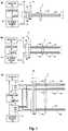
Fig. 1a, Fig. 1b and Fig. 1c illustrate respective embodiments of a portion of a system for detecting the presence of a cable in accordance with principles of the present invention;Fig. 2 is a more detailed perspective view of an exemplary electrocardiogram cable including a cable connector for interconnection to a patient monitor as utilized by the present invention;Fig. 3 is a block diagram of the interconnection between an electrocardiogram sensor, an electrocardiogram cable and a patient monitor including the cable presence detector according to principles of the present invention; andFig. 4 is a schematic diagram of the cable detector depicted inFig. 2 .- A processor, as used herein, operates under the control of an executable application to (a) receive information from an input information device, (b) process the information by manipulating, analyzing, modifying, converting and/or transmitting the information, and/or (c) route the information to an output information device. A processor may use, or comprise the capabilities of, a controller or microprocessor, for example. The processor may operate with a display processor or generator. A display processor or generator is a known element for generating signals representing display images or portions thereof. A processor and a display processor comprises any combination of, hardware, firmware, and/or software.
- An executable application, as used herein, comprises code or machine readable instructions for conditioning the processor to implement predetermined functions, such as those of an operating system, cable detection system or other information processing system, for example, in response to user command or input. An executable procedure is a segment of code or machine readable instruction, sub-routine, or other distinct section of code or portion of an executable application for performing one or more particular processes. These processes may include receiving input data and/or parameters, performing operations on received input data and/or performing functions in response to received input parameters, and providing resulting output data and/or parameters.
- A user interface (Ul), as used herein, comprises one or more display images, generated by the display processor under the control of the processor. The UI also includes an executable procedure or executable application. The executable procedure or executable application conditions the display processor to generate signals representing the Ul display images. These signals are supplied to a display device which displays the image for viewing by the user. The executable procedure or executable application further receives signals from user input devices, such as a keyboard, mouse, light pen, touch screen or any other means allowing a user to provide data to the processor. The processor, under control of the executable procedure or executable application manipulates the UI display images in response to the signals received from the input devices. In this way, the user interacts with the display image using the input devices, enabling user interaction with the processor or other device. A graphical user interface (GUI) uses graphical display images, as opposed to textual display images, when generating the UI.
Fig. 1a illustrates a portion of asystem 14 for detecting the presence of a cable in accordance with principles of the present invention. Thecable detection system 14 includes asource 16 of an inputelectrical AC signal 17. An output terminal of theAC signal source 16 is coupled to afirst lead pin 26 of acable connector 12. Adetector 42 is coupled to asecond lead pin 44 of thecable connector 12. Thedetector 42 detects an electricalAC output signal 38 derived by capacitive coupling of the inputelectrical AC signal 17 occurring within acable 2 incorporating first and second leads (e.g. 110 and 112) corresponding to the first and second lead pins (e.g. 26 and 44, respectively). InFig. 1a , the first and second leads (e.g. 110 and 112) are in the form of acoaxial cable 111. In the case illustrated inFig. 1a , thefirst lead 110 is a shield conductor of thecoaxial cable 111, and thesecond lead 112 is aninner conductor 112 of thecoaxial cable 111. Alternatively, thesecond lead 112 may be a shield of acoaxial cable 111 and thefirst lead 110 may be an inner conductor of acoaxial cable 111.- The first and second leads (e.g. 110 and 112) are coupled to a
cable plug 1 which connects them to the lead pins (e.g. 26 and 44, respectively) in thecable connector 12 when thecable plug 1 of thecable 2 is connected to thecable connector 12, as illustrated by the double arrow beneath thecable plug 1. Thedetector 42 enables a determination of whether thecable 2 is connected to thecable connector 12 in response to an amplitude dependent characteristic of the detectedAC output signal 38. - In operation, the first and second leads (e.g. 110 and 112) of the
cable 2 are capacitively coupled, as represented by a capacitor in phantom between the first and second leads (e.g. 110 and 112) at the right end of thecable 2. This capacitance, termed the characteristic capacitance, provides a path through which an AC signal, such as theAC input signal 17 received from theAC signal source 16, may pass from thefirst lead 110 to thesecond lead 112. There is also a capacitive coupling within thesystem 14, for example within thecable connector 12, represented by a capacitor in phantom fromlead pin 44 to leadpin 26 of thecable connector 12. However, this capacitance is smaller than the capacitance betweenleads cable 2 and consequently this impedance is larger than the impedance of thecable 2. - If the
cable 2 is connected, then theinput AC signal 17 from theAC signal source 16 is capacitively coupled from thefirst lead 110 to thesecond lead 112. Theoutput AC signal 38 in thesecond lead 112 is detected by thedetector 42. Thedetector 42 detects the amplitude of the receivedoutput AC signal 38 from thesecond lead 112. More specifically, thedetector 42 determines whether thecable 2 is connected to thecable connector 12 in response to an amplitude dependent characteristic of the detectedAC output signal 38 exceeding a predetermined threshold value. If thecable 2 is not connected, the AC signal from thefirst lead pin 26 is still capacitively coupled to thesecond lead pin 44 due to capacitive coupling within thesystem 14. But because the impedance is larger, the amplitude of theoutput AC signal 38 detected by thedetector 42 is smaller. The difference in amplitude of the detected AC signal enables determination of whether thecable 2 is connected to thecable connector 12. - The
system 14 further includes acontroller 24 for automatically initiating generation of the inputelectrical AC signal 17 for coupling to thefirst lead 110, and for turning off the inputelectrical AC signal 17 after determination by thedetector 42 of whether thecable 2 is connected to thecable connector 12. More specifically, the controller automatically synchronizes initiating generation of the inputelectrical AC signal 17, for coupling to thefirst lead 110, and detection by thedetector 42 of whether thecable 2 is connected to thecable connector 12 in response to atiming signal 53 to avoid interference with other signals. - In operation, the
controller 24 provides acontrol signal 53 to theAC signal source 16 conditioning theAC signal source 16 to produce theinput AC signal 17 in order to detect the presence of acable 2. If thedetector 42 detects the presence of acable 2, thecontroller 24 conditions theAC signal source 16 to turn off theAC input signal 17 to prevent interference with the signal processing provided by the remainder of the system 14 (not shown). - The
detector 42 may also determine the type ofcable 2 in response to an amplitude dependent characteristic of the detectedAC output signal 38. For example,different cables 2 have different characteristic capacitance. This results in different impedances for theAC input signal 17, and different detected amplitudes of the detectedoutput AC signal 38. Tests may be performed ondifferent cables 2 to determine the characteristic capacitance, and the corresponding amplitude of the detectedAC output signal 38. The results of these tests may be saved in amemory 52 in thecontroller 24. The amplitude of a detectedAC output signal 38 may be compared to the amplitudes saved in thememory 52 to determine the type ofcable 2 connected to thesystem 14. Thememory 52 may also store anAC output signal 38 value measured when thecable 2 is not connected to thecable connector 12. Thedetector 42 determines whether thecable 2 is connected to thecable connector 12 in response to the storedAC output signal 38 value measured when thecable 2 is not connected to thecable connector 12. Fig. 1b illustrates another embodiment of asystem 14 according to principles of the present invention. InFig. 1b , thecable detection system 14 includes asource 16 of an inputelectrical AC signal 17 for coupling to a first lead of acoaxial cable 111 of a multi-lead (i.e. multiple conductor)cable 2 via aconnector 12. Adetector 42 is coupled to a different second lead of acoaxial cable 113 of themulti-lead cable 2 via theconnector 12. Thedetector 42 automatically detects an electricalAC output signal 38 derived by capacitive coupling of the inputelectrical AC signal 17 occurring within themulti-lead cable 2 incorporating the first and second coaxial cables (111 and 113, respectively). Thedetector 42 further enables the determination of whether themulti-lead cable 2 is connected to thecable connector 12 in response to an amplitude dependent characteristic of the detectedAC output signal 38. Acontroller 24 automatically initiates generation of the inputelectrical AC signal 17 for coupling to the first lead ofcoaxial cable 111, and turns off the inputelectrical AC signal 17 after determination by thedetector 42 of whether themulti-lead cable 2 is connected to thecable connector 12.- In
Fig. 1b , the first lead is one of: (a) ashield 110 of a firstcoaxial cable 111, and/or (b) aninner conductor 112 of a firstcoaxial cable 111 incorporated in thecable 2, and the second lead is one of: (a) ashield 114 of a different secondcoaxial cable 113, and/or aninner conductor 116 of a different secondcoaxial cable 113 incorporated in thecable 2. - In this embodiment, there is a capacitive coupling between the conductors of the respective
coaxial cables inner conductors coaxial cables respective conductors coaxial cables Fig. 1a , thedetector 42 may determine the type of cable in response to an amplitude dependent characteristic of the detectedAC output signal 38. Fig. 1c is another embodiment of acable detection system 14 according to principles of the present invention. InFig. 1c , asource 16 of an inputelectrical AC signal 17 may be coupled to shield conductors (110, 114, ... 11y) of a plurality of leads (e.g. 111, 113, ... 11n) of amulti-lead cable 2 via aconnector 12. The plurality of leads (111, 113, ... 11n) of themulti-lead cable 2 may be coaxial cables, and include at least one inner conductor and at least one shield. Adetector 42 is also coupled to the inner conductors (112, 116, ... 11x) of the plurality of leads (e.g. 111, 113, ... 11n) of themulti-lead cable 2 via theconnector 12. Thedetector 42 detects an electricalAC output signal 38 derived by capacitive coupling of the inputelectrical AC signal 17 occurring within themulti-lead cable 2. Thedetector 42 enables determination of whether thecable 2 is connected to thecable connector 12 in response to an amplitude dependent characteristic of the detectedAC output signal 38. Acontroller 24 automatically initiates the determination of the amplitude dependent characteristic of a detectedAC output signal 38 on individual ones of the inner conductors (112, 116, ... 11x) of the plurality of leads (111, 113, ... 11n) of themulti-lead cable 2 in response to the input electrical AC signal being applied to individual leads of themulti-lead cable 2 one at a time.- The
AC input signal 17 from theAC signal source 16 is coupled to a signal input terminal of aswitch 120. Respective signal output terminals of theswitch 120 are coupled to corresponding shield conductors (110, 114, ... 11y) of the plurality of leads (111, 113, ... 11n) of themulti-lead cable 2. An output terminal of thecontroller 24 is coupled to a control input terminal of theswitch 120. Correspondingly, respective inner conductors (112, 116, ... 11x) of the plurality of leads (111, 113, ... 11n) are coupled to respective signal input terminals of a switch 122. An output terminal of the switch 122 provides theAC output signal 38 and is coupled to an input terminal of thedetector 42. An output terminal of thecontroller 24 is coupled to a control input terminal of the switch 122. - The
switch 120 operates to couple theinput AC signal 17 from theAC signal source 16 to a conductor of a selected one of the plurality of leads (111, 113, ... 11n) in response to the value of thecontrol signal 53 from thecontroller 24 to theswitch 120. Concurrently, the switch 122 operates to couple a conductor of a selected one of the plurality of leads (111, 113, ... 11n) to thedetector 42 in response to the value of thecontrol signal 53 from thecontroller 24 to the switch 122. In this manner, thecontroller 24 may initiate determination of the amplitude dependent characteristic of the detectedAC output signal 38 on individual ones of the plurality of leads (111, 113, ... 11n) by providing appropriate control signals 53 to theswitches 120 and 122. - In operation, the
AC signal source 16 generates an alternatingcurrent signal 17. The alternatingcurrent signal 17 is applied to a first conductor (e.g. 110) of themulti-lead cable 2 via theswitch 120. An alternating current signal at a second conductor (e.g. 112) of themulti-lead cable 2 is detected by coupling of the selected second conductor (e.g. 112) to thedetector 42 via switch 122. The alternating current signal at the second conductor (e.g. 112) of themulti-lead cable 2 is detected to produce a detected signal. A proper interconnection of themulti-lead cable 2 to thecable connection 12 is identified in response to a characteristic of the detected signal. More specifically, the alternatingcurrent signal 17 is sequentially applied to the plurality of shield conductors (110, 114, ... 11y) of the plurality of leads (111, 113, ... 11n) of themulti-lead cable 2. The cable type is determined in response to the detected presence or absence of an inner conductor (112, 116, ... 11x) of the plurality of leads (111,113, ... 11n). This may be done by associating a particular combination of leads (e.g. 111, 113, ... 11n) present within themulti-lead cable 2 with a specific type of cable. After the specific type of cable has been identified, the generation of the alternating current signal is suppressed. - The
detector 42 determines a type of cable connected to thesystem 14 in response to a plurality of measurements of amplitude dependent characteristics of the detectedAC output signal 38 on a plurality of inner conductors (112, 116, ... 11x) of the plurality of leads (111, 113, ... 11n) of themulti-lead cable 2. For example, particular ones of the plurality of inner conductors (112, 116, ... 11x) may be detected while other particular ones of the plurality of inner conductors (112, 116, ... 11x) may not be detected, i.e. not be present in themulti-lead cable 2. This provides an indication of the number and arrangement of leads in themulti-lead cable 2. Further, the plurality of measurements of the amplitude dependent characteristic of the detectedAC output signal 38 may be compared to predetermined sets of such measurements stored in thememory 52 to provide additional information related to the type of cable connected to thesystem 14. - The amplitude dependent characteristic of the detected
AC output signal 38 may comprise a detected voltage substantially proportional to: (a) a peak to peak amplitude, (b) a root-mean-square amplitude, and/or (c) an average rectified amplitude value, of the detectedAC output signal 38. Thedetector 42 determines whether amulti-lead cable 2 is connected to thecable connector 12 in response to the detected voltage exceeding a predetermined threshold value. In addition, synchronous demodulation may be employed to sense only the signal of interest, i.e. theoutput AC signal 38 derived from theinput AC signal 17, and to reject spurious signals. - A more detailed cable connector or
plug 1 is illustrated inFig. 2 . Theconnector 1 serves as the termination point for amulti-conductor cable 2, thecable 2 receiving multiple power, control and data signals, for example, from an electronic device such as a patient monitor. Thecable 2 is typically formed to include a plurality of coaxial cables comprising respective centrally located conductors substantially surrounded by corresponding shields. This configuration has significant inherent characteristic capacitance which is typically more easily detected than would be possible in the case of a ribbon or other non-coaxial cable. - The
connector 1 includes a grip 3 that contains suitable mechanical transitions to permit individual coaxial cables within thecable 2 to be separated and the centrally located conductors terminated at individual pins, e.g. 4, 5, 6, 7 and 8. Each pin is surrounded by ashield 9. Theshield 9 is connected to the shield associated with the centrally located conductor connected to the pin. Theshield 9 is typically maintained at a nominal reference or ground potential. The respective shields of the plurality of coaxial cables in thecable 2 may also be interconnected to an electrically conductive jacket that surrounds the coaxial cables within thecable 2. - The
cable 2 typically terminates at each end with a substantiallyidentical connector 1. The number of pins shown is merely exemplary and thecable 2 may in practice contain either a fewer or greater number of individual conductors as may be appropriate for the particular devices being interconnected. However, the present invention is particularly advantageous when used in conjunction with a cable that has been standardized for a particular industry and where the number of conductors within thecable 2 is not only fixed, but typically all of the conductors are already dedicated to some use by the interconnected device. - An example of a device that utilizes a
multi-conductor interconnection cable 2 is theelectrocardiogram sensor 10 illustrated inFig. 3 . Thesensor 10 is placed into contact with the skin of a human patient in order to obtain physiological data. Alternatively, thesensor 10 may include conductors (not shown) which connect to a plurality of sensors which are placed into contact with the skin of a patient. Thesensor 10 includes thecable 2 which terminates at theplug 1. The data collected by thesensor 10 is transferred to apatient monitor 13 via thecable 2, the patient monitor 13 includes acable connector 12 which is adapted to receive theplug 1. In this manner the data generated by thesensor 10 may be suitably displayed on adisplay device 11 used to display a patient monitor user interface (Ul). In this embodiment, thedisplay device 11 displays ECG lead signal waveforms for inspection by medical personnel. - In order to ensure the integrity and/or correct configuration of the data appearing on the
user interface 11, the patient monitor 13 includes acable detector 14. As best seen inFig. 4 , thecable detector 14 includes an alternatingcurrent signal source 16 that generates a relatively lowamplitude level signal 17. Typically thesignal 17 has an amplitude value of approximately three volts peak to peak, a current value of thirty three microamperes, and is generated as an approximately eighty kilohertz (kHz) sine or square wave. A typical ECG cable also carries an AC signal used for impedance measurement of respiration. The nominally eighty kHzsignal 17 is selected to be approximately twice the frequency of the respiration measurement signal in order to avoid beat frequency or mixing product interference with other measurements. - The
signal 17 is sent to a resistor-capacitor (RC) filter 20 that includes aresistor 18 and acapacitor 19. The nominal value of theresistor 18 is approximately three thousand ohms while the value of the capacitor is typically thirty three hundred picofarads. When processing the eighty kilohertz frequency of thesignal 17, the resultant time constant of theRC filter 20 tends to make a squarewave input signal 17 more sinusoidal, which is desirable in order to reduce rapid transition edge noise coupling. Thesignal 17 is coupled into at least one of the cable leads 4-9 viacoupling capacitor 21 which has a nominal value of thirty three hundred picofarads. - The eighty kilohertz (kHz)
signal 17 is interconnected to theshield conductor 9 via either afirst switch 22 or asecond switch 23. For example, a firstsignal source controller 24 automatically applies afirst control signal 36 tofirst switch 22 to complete the circuit between thesignal 17 and thesocket shield 26 that is associated with thesocket connector 27. Thesocket shield 26 is nominally at the same potential as theshield conductor 9, which is nominally atground potential 31. Afirst coupling resistor 28, having a nominal value of one thousand ohms, is present in thesignal path 29 and allows a relatively larger amount of current to reach theshield 26 as may be appropriate for a cable having a first, relatively lower value of inherent cable coupling (i.e characteristic) capacitance. The firstsignal source controller 24 is also interconnected to aswitch 39, which controls access of thesignal path 41 to thedetection signal amplifier 42 via acoupling capacitor 50 having a nominal value of thirty three hundred picofarads. - A second
signal source controller 25, which may be integrated with thefirst controller 24, applies asecond control signal 37 to asecond switch 23 in order to complete the circuit between thesignal 17 and thesocket shield 34 that is associated with thesocket connector 35. Thesocket shield 34 is nominally at the same potential as theshield conductor 9, which is nominally atground potential 31. Asecond coupling resistor 32, having a nominal value of approximately one thousand ohms, is present insignal path 33 and allows a relatively smaller amount of current to reach theshield 34 as may be appropriate for a cable having a second, relatively higher value of inherent cable coupling capacitance. Aradio frequency choke 30, having a nominal value of sixty eight hundred microhenries, serves to attenuate any higher frequency signal energy which may be coupled into theshield conductor 9. The secondsignal source controller 25 is also interconnected to aswitch 40, which controls access of thesignal path 43 to thedetection signal amplifier 42 via acoupling capacitor 51 having a nominal value of thirty three hundred picofarads. While interconnections tosocket connectors controllers pins 44 and 46-49. Thesignal source controllers monitor cable socket 12 as needed. Atiming signal 53, which may be interconnected to one or bothcontrollers AC signal 17 when the presence ofsignal 17 would cause harmful interference to other signals being received or processed by thepatient monitor 13. - In operation, the
signal 17 is coupled to one of theshield conductors 9 of thecable 2, creating a relativelylarger detection signal 38 by completing the circuit through another of the cable leads, if and when thecable 2 is properly plugged into thepatient monitor 13. Thedetection signal 38 is relatively smaller when thecable 2 is absent. The additional amplitude of thedetection signal 38 when thecable 2 is present is proportional to the inherent capacitance between the cable leads withincable 2 and is used to distinguish between thecable 2 being present or not being present. For example, a typicalpatient monitor cable 2 has a nominal interelectrode capacitance of one hundred pf. Thus a given patientmonitor connector pin 44 will be loaded by more than one hundred pf capacitance value if thecable 2 is properly inserted. - The resulting detected
signal voltage 38 that is detected on thesignal lead 44, for example is buffered, rectified and filtered by thesignal detection amplifier 42 in order to produce a processedoutput signal 45. Synchronous detection or demodulation may be employed by thesignal detection amplifier 42 when thedetection signal 38 includes a noise or other spurious signal component, or an actual sensor data or excitation signal such as may occur in the case of electrocardiogram, respiration or blood oxygen saturation signals. - The processed
signal 45 is sent to an analog to digital (A/D)converter 15 that is typically already a part of the patient monitor 13 (Fig. 3 ) in order to permit additional software processing and to enable the appropriate data presentation on the patientmonitor display device 11. The processedsignal 45 typically has an amplitude voltage characteristic that is substantially proportional to a peak to peak amplitude value, a root-mean-square value and/or an average rectified value. In a preferred embodiment, the processedsignal 45 has a value of at least three hundred millivolts when thecable 2 is present and a value of approximately one millivolt when thecable 2 is absent. Thus a threshold value in excess of the three hundred millivolts will trigger signal processing software within the patient monitor 13 to recognize the presence of a properly connectedcable 2. - An initial baseline value of the capacitively coupled eighty kHz
signal 38 amplitude in the absence of thesensor cable 2 is stored inmemory 52 and is therefore available to be subtracted from the absolute amplitude of the detectedsignal 38, thereby providing a relatively more accurate comparison of the value of the detectedsignal 38 for the cable present versus cable absent states. After the cable detection process is completed, the eighty kHzsignal source 16 is turned off by thecontrollers 24 and/or 25 in order to reduce interference with the actual sensor data, such as ECG and respiration detection, which typically utilize the same cable conductors. - In operation, one
connector pin signal source controllers cable 2 is a typical ECG cable, it may be one of four different types, where the number of conductors may be three, five six or twelve, respectively. The electrodes are placed at various standard points on the patient's body to provide electrode lead data with designations such as V1, V2, V3, V4, V5, V6, RA, LA and LL, with an additional lead being connected to system ground, which is typically the patient's right leg. Some of the electrode designations are present in cables having a given number of conductors. A twelve conductor cable, for example, is theonly cable 2 that contains the V1 lead, while a six conductor cable is the only cable that contains the V5 lead without a V1 lead. A five conductor cable contains the V2 lead without the V1 or V5 lead, while a two conductor cable contains only the RA lead without the other leads being present. Thus only one ECG pin (e.g. RA, V2, V5, and V1) from each of the four (3, 5, 6, or 12 lead) possible types of ECG cables needs to be tested. A combination of the four cable detected signals allows determination of which type of ECG cable is connected to the patient monitor 13 and enables the appropriate ECG display and monitoring function, including the configuration of the ECG display, to be selected by any patient monitor software. - While the invention has been described with reference to a specific embodiment, various modifications may be made. In particular, the
controllers signal source 16 may be other than eighty kHz, and in some cases may be modulated in order to determine additional characteristics of thecable 2 or the integrity of the connection to thesocket 12. Thesignal source 16 may introduce thesignal 17 at the center conductor of a cable or at the shield, and various intervening components may be present in addition to those illustrated in the figures. While anECG cable 2 has been disclosed in the preferred embodiment, many types of industry standard cables may be used and the number and arrangement of conductors automatically determined based on the detection of the presence or absence of a conductor at certain standard, identifiable pins locations. - Although the invention has been described in terms of exemplary embodiments, it is not limited thereto. Rather, the appended claims should be construed broadly to include other variants and embodiments of the invention which may be made by those skilled in the art without departing from the scope and range of equivalents of the invention. This disclosure is intended to cover any adaptations or variations of the embodiments discussed herein.
Claims (19)
- A cable detection system (14), comprising:a source (16) of an input electrical AC signal (17) for coupling to a first lead pin (26) of a cable connector (12) and for providing said input electrical AC signal to the first lead pin; anda detector (42) coupled to a different second lead pin (44) of said cable connector for detecting an electrical AC output signal derived by capacitive coupling of said input electrical AC signal occurring within a multi-lead cable incorporating first and second leads corresponding to said first and second lead pins and for enabling determination of whether said multi-lead cable is connected to said cable connector in response to comparing an amplitude dependent characteristic of said detected AC output signal with a predetermined threshold value to determine if said amplitude dependent characteristic exceeds said threshold value; and wherein said detector determines a type of said multi-lead cable in response to an amplitude dependent characteristic of said detected AC output signal.
- A system according to claim 1 including a controller for automatically initiating generation of said input electrical AC signal for coupling to said first lead and for turning off said input electrical AC signal after determination by said detector of whether said multi-lead cable is connected to said cable connector.
- A system according to claim 1, wherein:said first lead is a shield of a coaxial cable (111); andsaid second lead is an inner conductor of said coaxial cable.
- A system according to claim 1, wherein:said second lead is a shield of a coaxial cable; andsaid first lead is an inner conductor of said coaxial cable.
- A system according to claim 1, wherein:said first lead is at least one of, (a) a shield of a first coaxial cable and (b) an inner conductor of a first coaxial cable incorporated in said multi-lead cable; andsaid second lead is at least one of, (c) a shield of a different second coaxial cable and (d) an inner conductor of a different second coaxial cable incorporated in said multi-lead cable.
- A system according to claim 1, further comprising:a memory (52) for storing an AC output signal value measured when said multi-lead cable is not connected to said connector; wherein:said detector determines whether said multi-lead cable is connected to said cable connector in response to said stored AC output signal value measured when said multi-lead cable is not connected to said connector.
- A system according to claim 1, further comprising a controller (24) for automatically synchronizing initiating generation of said input electrical AC signal for coupling to said first lead and detection by said detector of whether said multi-lead cable is connected to said cable connector in response to a timing signal to avoid interference with other signals.
- A system according to claim 1, further comprising a controller (24) for automatically initiating generation of said input electrical AC signal for coupling to said first lead and for turning off said input electrical AC signal after determination by said detector of whether said cable is connected to said cable connector.
- A system according to claim 8, wherein said detector determines a type of said cable in response to an amplitude dependent characteristic of said detected AC output signal.
- A system according to claim 8, further comprising a controller for automatically initiating determination of said amplitude dependent characteristic of a detected AC output signal on individual ones of a plurality of leads of said multi-lead cable, in response to said input electrical AC signal being applied to individual leads of a plurality of leads of said multi-lead cable one at a time.
- A system according to claim 1, wherein said detector determines a type of said multi-lead cable in response to a plurality of measurements of amplitude dependent characteristic of said detected AC output signal on a plurality of leads of said multi-lead cable.
- A system according to claim 1, wherein said plurality of leads of said multi-lead cable include at least one inner conductor and at least one shield of a coaxial cable.
- A system according to claim 1, wherein said amplitude dependent characteristic of said detected AC output signal comprises a detected voltage substantially proportional to at least one of, (a) a peak to peak amplitude, (b) a root-mean-square and (c) an average rectified value, value of said detected AC output signal and said detector determines whether said multi-lead cable is connected to said cable connector in response to said detected voltage exceeding a predetermined threshold value.
- A system according to claim 1, wherein synchronous demodulation is employed to sense only the signal of interest and to reject spurious signals.
- A method of identifying proper interconnection of a multiple conductor cable to a cable connector, comprising the steps of:generating an input electrical alternating current signal;applying the input electrical alternating current signal to a first conductor of the cable;detecting an electrical alternating current output signal at a second conductor of the cable to produce a detected signal, wherein the electrical alternating current output signal is derived by capacitive coupling of said input electrical alternating current signal occurring within the multiple conductor cable;identifying a proper interconnection in response to comparing an amplitude dependent characteristic of the detected signal with a predetermined threshold value to determine if said amplitude dependent characteristic exceeds said threshold value;sequentially applying the alternating current signal to a plurality of conductors of the cable; anddetermining a cable type in response to an amplitude dependent characteristic of said detected AC output signal.
- The method of claim 15, wherein determining a cable type in response to an amplitude dependent characteristic of said detected AC output signal comprises determining a cable type in response to a presence or absence of a conductor.
- The method of claim 16, further comprising the step of determining a display configuration in response to the determined cable type.
- The method of claim 16, further comprising the step of associating a particular combination of conductors within the cable with a specific type of cable.
- The method of claim 18, further comprising the step of suppressing generation of the alternating current signal after the specific type of cable has been identified.
Applications Claiming Priority (2)
| Application Number | Priority Date | Filing Date | Title |
|---|---|---|---|
| US87124906P | 2006-12-21 | 2006-12-21 | |
| PCT/US2007/088497WO2008080036A2 (en) | 2006-12-21 | 2007-12-21 | A cable detection system |
Publications (2)
| Publication Number | Publication Date |
|---|---|
| EP2092357A2 EP2092357A2 (en) | 2009-08-26 |
| EP2092357B1true EP2092357B1 (en) | 2019-02-20 |
Family
ID=39471615
Family Applications (1)
| Application Number | Title | Priority Date | Filing Date |
|---|---|---|---|
| EP07869714.1AActiveEP2092357B1 (en) | 2006-12-21 | 2007-12-21 | A cable detection system |
Country Status (4)
| Country | Link |
|---|---|
| US (1) | US7902810B2 (en) |
| EP (1) | EP2092357B1 (en) |
| CN (1) | CN101563619B (en) |
| WO (1) | WO2008080036A2 (en) |
Families Citing this family (82)
| Publication number | Priority date | Publication date | Assignee | Title |
|---|---|---|---|---|
| US7746081B2 (en)* | 2006-12-08 | 2010-06-29 | General Electric Company | Cable detection method and apparatus |
| US8203325B2 (en)* | 2007-09-07 | 2012-06-19 | Analog Devices, Inc. | Activation systems and methods to initiate HDMI communication with mobile sources |
| DE102008008708A1 (en)* | 2007-12-21 | 2009-06-25 | Endress + Hauser Process Solutions Ag | Method for determining damage to a connecting line and corresponding device and electromagnetic flowmeter |
| DE102008043491B4 (en)* | 2008-11-05 | 2015-04-02 | Airbus Operations Gmbh | Apparatus and method for testing a connector |
| US8128428B2 (en)* | 2009-02-19 | 2012-03-06 | Panduit Corp. | Cross connect patch guidance system |
| DE102009021986A1 (en)* | 2009-05-19 | 2010-11-25 | KMT Külzer Medizintechnik GmbH | An ultrasound probe test apparatus, an ultrasound measuring apparatus and a method of testing an ultrasound probe |
| US8237427B2 (en)* | 2009-06-16 | 2012-08-07 | Textron Innovations Inc. | Wideband high impedance bridging module |
| US20110152962A1 (en)* | 2009-12-21 | 2011-06-23 | Medtronic, Inc. | Cable Detection System |
| CN102818966B (en)* | 2011-12-19 | 2015-06-03 | 中国人民解放军驻六一三所军事代表室 | Testing cable misinsertion prevention method and system for virtual instrument |
| DE102013209593B4 (en)* | 2013-05-23 | 2017-05-18 | Getemed Medizin- Und Informationstechnik Ag | Arrangement for providing a long-term ECG |
| JP2015002554A (en)* | 2013-06-18 | 2015-01-05 | 船井電機株式会社 | Wired communication device and wired communication method |
| CN103335676B (en)* | 2013-06-28 | 2016-04-06 | 南京邮电大学 | A kind of method of the detection streamer information based on infrared sound hybrid ranging |
| WO2015009315A1 (en)* | 2013-07-19 | 2015-01-22 | Draeger Medical Systems, Inc. | Cable detection system and method |
| US9222964B2 (en) | 2013-10-07 | 2015-12-29 | Lenovo Enterprise Solutions (Singapore) Pte. Ltd. | Cable detection in a pin constrained connector |
| CN103792431B (en)* | 2014-01-23 | 2016-03-09 | 太原工业学院 | Clock spring cable micro-ohm resistance and insulation resistance clamped one time precision measuring instrument |
| CN103809074B (en)* | 2014-03-10 | 2016-04-27 | 江苏省电力公司盐城供电公司 | A kind of power cable safety distinguishing apparatus and recognition methods |
| US10531977B2 (en) | 2014-04-17 | 2020-01-14 | Coloplast A/S | Thermoresponsive skin barrier appliances |
| US9645183B2 (en)* | 2014-08-20 | 2017-05-09 | At&T Intellectual Property I, L.P. | Methods, systems, and products for power management in cable assemblies |
| CN104330685B (en)* | 2014-11-06 | 2017-08-11 | 湖南南车时代电动汽车股份有限公司 | A kind of line inspection method and line inspection device |
| CN104469347B (en)* | 2014-12-08 | 2016-08-24 | 硅谷数模半导体(北京)有限公司 | The testing circuit of video transmission cable and video frequency output chip |
| CN104569719B (en)* | 2014-12-31 | 2017-10-27 | 贝兹维仪器(苏州)有限公司 | A kind of multi-core cable test system |
| US10617356B2 (en)* | 2016-03-15 | 2020-04-14 | Anhui Huami Information Technology Co., Ltd. | Garment and cardiac data processing |
| EP3264279A1 (en)* | 2016-06-28 | 2018-01-03 | Thomson Licensing | Switch for reversible interface |
| US11064970B2 (en)* | 2016-12-05 | 2021-07-20 | Fujifilm Sonosite, Inc. | Method and apparatus for visualizing a medical instrument under ultrasound guidance |
| EP3627977B1 (en)* | 2017-05-16 | 2022-11-02 | Fuji Corporation | Plasma generator |
| US10359464B2 (en)* | 2017-09-18 | 2019-07-23 | Biosense Webster (Israel) Ltd. | Cable and associated continuity monitoring system and method |
| US11103298B2 (en) | 2017-10-31 | 2021-08-31 | Covidien Lp | Systems and methods for detecting insertion or removal of a cable |
| US10288663B1 (en) | 2017-11-01 | 2019-05-14 | Saudi Arabian Oil Company | Method and apparatus for injecting current over an electrical conductor |
| US10261114B1 (en)* | 2017-12-05 | 2019-04-16 | General Electric Company | Device and method for device detection using electrical non-linear characteristics |
| US10690863B1 (en)* | 2017-12-13 | 2020-06-23 | Amazon Technologies, Inc. | Communication cable identification |
| WO2019120442A1 (en) | 2017-12-22 | 2019-06-27 | Coloplast A/S | Sensor assembly part and a base plate for an ostomy appliance and a device for connecting to a base plate or a sensor assembly part |
| DK3729456T3 (en) | 2017-12-22 | 2022-03-07 | Coloplast As | MONITORING DEVICE FOR AN OSTOMY SYSTEM AND ASSOCIATED METHOD FOR OPERATING A MONITORING DEVICE |
| EP4032511A1 (en) | 2017-12-22 | 2022-07-27 | Coloplast A/S | Ostomy appliance with sensing zones |
| US11471318B2 (en) | 2017-12-22 | 2022-10-18 | Coloplast A/S | Data collection schemes for a medical appliance and related methods |
| WO2019120438A1 (en) | 2017-12-22 | 2019-06-27 | Coloplast A/S | Tools and methods for placing an ostomy appliance on a user |
| EP3727245B1 (en) | 2017-12-22 | 2025-04-30 | Coloplast A/S | Data transmission schemes for an ostomy system, monitoring device for an ostomy device, and associated methods |
| JP2021508269A (en) | 2017-12-22 | 2021-03-04 | コロプラスト アクティーゼルスカブ | A method for manufacturing a base plate for an ostomy orthosis and a sensor assembly part for the base plate, and a base plate and a sensor assembly part. |
| AU2018391313B2 (en) | 2017-12-22 | 2024-05-02 | Coloplast A/S | Accessory devices of an ostomy system, and related methods for communicating operating state |
| EP4245273A3 (en) | 2017-12-22 | 2023-11-08 | Coloplast A/S | Base plate and sensor assembly of an ostomy system having a leakage sensor |
| US11707377B2 (en) | 2017-12-22 | 2023-07-25 | Coloplast A/S | Coupling part with a hinge for a medical base plate and sensor assembly part |
| US10799385B2 (en) | 2017-12-22 | 2020-10-13 | Coloplast A/S | Ostomy appliance with layered base plate |
| US10849781B2 (en) | 2017-12-22 | 2020-12-01 | Coloplast A/S | Base plate for an ostomy appliance |
| LT4032510T (en) | 2017-12-22 | 2025-08-25 | Coloplast A/S | BASE BOARD WITH SELECTIVE SENSOR POINTS AND METHOD FOR MANUFACTURING THEREOF |
| US10500084B2 (en) | 2017-12-22 | 2019-12-10 | Coloplast A/S | Accessory devices of an ostomy system, and related methods for communicating leakage state |
| WO2019120441A1 (en) | 2017-12-22 | 2019-06-27 | Coloplast A/S | Sensor assembly part and a base plate for an ostomy appliance and a method for manufacturing a sensor assembly part and a base plate |
| JP7462558B2 (en) | 2017-12-22 | 2024-04-05 | コロプラスト アクティーゼルスカブ | Ostomy system and monitor device with angular leak detection - Patents.com |
| EP4248920A3 (en) | 2017-12-22 | 2023-12-27 | Coloplast A/S | Ostomy appliance system, monitor device, and method of monitoring an ostomy appliance |
| EP3727219B1 (en) | 2017-12-22 | 2023-08-09 | Coloplast A/S | Moisture detecting base plate for an ostomy appliance and a system for determining moisture propagation in a base plate and/or a sensor assembly part |
| US11627891B2 (en) | 2017-12-22 | 2023-04-18 | Coloplast A/S | Calibration methods for medical appliance tools |
| EP4042987B1 (en) | 2017-12-22 | 2025-02-12 | Coloplast A/S | Monitor device of an ostomy system having a connector for coupling to both a base plate and an accessory device |
| WO2019120431A1 (en) | 2017-12-22 | 2019-06-27 | Coloplast A/S | Tools and methods for cutting holes in an ostomy appliance |
| US11607334B2 (en) | 2017-12-22 | 2023-03-21 | Coloplast A/S | Base plate for a medical appliance, a monitor device and a system for a medical appliance |
| EP3727222B1 (en) | 2017-12-22 | 2024-05-08 | Coloplast A/S | Sensor assembly part for an ostomy appliance and a method for manufacturing a sensor assembly part |
| LT3727228T (en) | 2017-12-22 | 2022-08-10 | Coloplast A/S | MAIN BOARD AND SENSOR STRUCTURE PART FOR OSTOMY DEVICE AND METHOD OF MANUFACTURING THE MAIN BOARD AND SENSOR STRUCTURE PART |
| US11654043B2 (en) | 2017-12-22 | 2023-05-23 | Coloplast A/S | Sensor assembly part and a base plate for a medical appliance and a method for manufacturing a base plate or a sensor assembly part |
| EP3727231B2 (en) | 2017-12-22 | 2025-03-12 | Coloplast A/S | Processing schemes for an ostomy system, monitor device for an ostomy appliance and related methods |
| JP6947042B2 (en)* | 2018-01-09 | 2021-10-13 | 日立金属株式会社 | Multi-core cable inspection method, multi-core cable assembly manufacturing method, and multi-core cable inspection equipment |
| JP6947041B2 (en)* | 2018-01-09 | 2021-10-13 | 日立金属株式会社 | Multi-core cable inspection method, multi-core cable assembly manufacturing method, and multi-core cable inspection equipment |
| WO2019161861A1 (en) | 2018-02-20 | 2019-08-29 | Coloplast A/S | Sensor assembly part and a base plate for an ostomy appliance and a device for connecting to a base plate and/or a sensor assembly part |
| US12208029B2 (en) | 2018-02-20 | 2025-01-28 | Coloplast A/S | Base plate having a mechanical and electrical connector |
| EP4631480A2 (en) | 2018-02-20 | 2025-10-15 | Coloplast A/S | Accessory devices of an ostomy system, and related methods for changing an ostomy appliance based on future operating state |
| US11903728B2 (en) | 2018-03-15 | 2024-02-20 | Coloplast A/S | Methods of configuring medical notifications and related accessory devices |
| US11998474B2 (en) | 2018-03-15 | 2024-06-04 | Coloplast A/S | Apparatus and methods for navigating ostomy appliance user to changing room |
| DE102018117815A1 (en)* | 2018-07-24 | 2020-01-30 | Amad - Mennekes Holding Gmbh & Co. Kg | Monitoring of the contact area in a connector |
| EP3837520B1 (en) | 2018-08-15 | 2025-10-08 | Coloplast A/S | Accessory device of an ostomy system and related methods for issue identification |
| EP3897481B1 (en) | 2018-12-20 | 2023-08-09 | Coloplast A/S | Ostomy condition classification with masking, devices and related methods |
| EP3897482B1 (en) | 2018-12-20 | 2025-07-16 | Coloplast A/S | Ostomy condition classification with image data transformation, devices and related methods |
| JP6645669B1 (en)* | 2019-01-21 | 2020-02-14 | Necプラットフォームズ株式会社 | Interface circuit, information processing device, display method, and program |
| KR102825171B1 (en) | 2019-01-31 | 2025-06-25 | 컬러플라스트 에이/에스 | Sensor patch for ostomy/urinary device |
| US11612512B2 (en) | 2019-01-31 | 2023-03-28 | Coloplast A/S | Moisture detecting base plate for an ostomy appliance and a system for determining moisture propagation in a base plate and/or a sensor assembly part |
| WO2020156624A1 (en) | 2019-01-31 | 2020-08-06 | Coloplast A/S | Application of a stomal sensor patch |
| CN113365582B (en) | 2019-01-31 | 2024-12-31 | 科洛普拉斯特公司 | Stoma Sensor Patch |
| US12257172B2 (en) | 2019-02-28 | 2025-03-25 | Coloplast A/S | Sensor patch for attachment to a base plate |
| US10996275B2 (en) | 2019-03-19 | 2021-05-04 | Saudi Arabian Oil Company | Low voltage ride-through test apparatus and method of using same |
| US11009561B2 (en)* | 2019-03-21 | 2021-05-18 | Jabil Inc. | Cable identification tester |
| EP3734300A1 (en)* | 2019-04-30 | 2020-11-04 | Koninklijke Philips N.V. | Locating an error in a supply or signal line of a magnetic resonance system |
| EP4512377A3 (en) | 2020-04-14 | 2025-04-30 | Coloplast A/S | METHOD FOR A MONITORING DEVICE FOR A PERSONAL CARE SYSTEM |
| CN111722149A (en)* | 2020-06-12 | 2020-09-29 | 浪潮电子信息产业股份有限公司 | A cable detection device, method, system and computer-readable storage medium |
| USD970017S1 (en) | 2020-08-25 | 2022-11-15 | Coloplast A/S | Ostomy appliance monitor |
| US20220160282A1 (en)* | 2020-11-25 | 2022-05-26 | Physio-Control, Inc. | Providing a Live-Lead View |
| WO2024226618A1 (en)* | 2023-04-27 | 2024-10-31 | St. Jude Medical, Cardiology Division, Inc. | Method and systems for cable attachment detection |
| CN119986470A (en)* | 2023-11-10 | 2025-05-13 | 浩亭股份有限公司 | Remote monitoring system and method for connectors |
Family Cites Families (16)
| Publication number | Priority date | Publication date | Assignee | Title |
|---|---|---|---|---|
| IL45786A (en) | 1974-10-04 | 1977-08-31 | Yeda Res & Dev | Heart beat detector |
| US4173221A (en)* | 1977-04-15 | 1979-11-06 | Wallace Rogozinski | EKG cable monitoring system |
| US5260659A (en)* | 1989-02-13 | 1993-11-09 | Radiodetection Limited | Method and apparatus for tracing conductors using an alternating signal having two components related in frequency and phase |
| US5231357A (en) | 1990-05-09 | 1993-07-27 | Panduit Corp. | Apparatus for testing a wire harness and method of use |
| DE69124244T2 (en) | 1991-11-12 | 1997-08-21 | Molex Inc | Wire presence and identification system |
| US5559427A (en)* | 1994-04-04 | 1996-09-24 | Fluke Corporation | Instrument and method for testing local area network cables |
| US5530367A (en)* | 1995-01-06 | 1996-06-25 | Fluke Corporaton | Pulse based cable attenuation measurement system |
| US5649001A (en)* | 1995-03-24 | 1997-07-15 | U.S. Robotics Mobile Communications Corp. | Method and apparatus for adapting a communication interface device to multiple networks |
| US6002247A (en) | 1996-08-07 | 1999-12-14 | Watkins; Lee A. | Method for determining correct pairing of bundled twisted wire pair circuitry |
| DE19757823C2 (en)* | 1997-12-24 | 1999-10-14 | Bosch Gmbh Robert | Test facility for connectors |
| US6829779B1 (en)* | 1998-09-16 | 2004-12-07 | Webtv Networks, Inc. | User interface for entertainment system setup |
| US6385297B2 (en)* | 1998-11-03 | 2002-05-07 | Teradyne, Inc. | Method and apparatus for qualifying loops for data services |
| US6896541B2 (en)* | 2003-02-18 | 2005-05-24 | Hewlett-Packard Development Company, L.P. | Interface connector that enables detection of cable connection |
| CN2663997Y (en)* | 2003-11-27 | 2004-12-15 | 董伟 | Multipurpose instrument for detecting cable fault under mine |
| JP2007221660A (en) | 2006-02-20 | 2007-08-30 | Fujifilm Corp | Image distribution system, image distribution server, and image distribution method |
| US7770036B2 (en) | 2006-02-27 | 2010-08-03 | Apple Inc. | Power management in a portable media delivery system |
- 2007
- 2007-12-21EPEP07869714.1Apatent/EP2092357B1/enactiveActive
- 2007-12-21CNCN2007800472918Apatent/CN101563619B/enactiveActive
- 2007-12-21USUS11/962,239patent/US7902810B2/enactiveActive
- 2007-12-21WOPCT/US2007/088497patent/WO2008080036A2/enactiveApplication Filing
Non-Patent Citations (1)
| Title |
|---|
| None* |
Also Published As
| Publication number | Publication date |
|---|---|
| EP2092357A2 (en) | 2009-08-26 |
| CN101563619A (en) | 2009-10-21 |
| US20090167286A1 (en) | 2009-07-02 |
| US7902810B2 (en) | 2011-03-08 |
| CN101563619B (en) | 2012-07-18 |
| WO2008080036A2 (en) | 2008-07-03 |
| WO2008080036A3 (en) | 2008-08-21 |
Similar Documents
| Publication | Publication Date | Title |
|---|---|---|
| EP2092357B1 (en) | A cable detection system | |
| CN111700605B (en) | Detecting disturbances in measuring bioelectric signals | |
| US6497659B1 (en) | System for identifying a cable transmitting a signal from a sensor to an electronic instrument | |
| US20100004547A1 (en) | ECG System for Use in ECG Signal Measurement of Intra-Cardiac ECG Using a Catheter | |
| US7260428B2 (en) | Shield arrangement for ECG lead wires | |
| CN110488133B (en) | Detecting signal path damage in measuring bioelectric signals | |
| JPH04227229A (en) | Electrocardiogram system | |
| US10838017B2 (en) | Cable and associated continuity monitoring system and method | |
| WO2015009315A1 (en) | Cable detection system and method | |
| US9918653B2 (en) | Electrophysiology catheter | |
| JP6306889B2 (en) | Bioelectrode adapter and bioelectric signal acquisition apparatus using the same | |
| CN114431863A (en) | System for measuring electrode contact impedance and impedance measuring method | |
| EP3912583A1 (en) | Testing electrode quality | |
| US6157855A (en) | Medical apparatus | |
| CN111398663B (en) | Cardiac pacemaker induction current testing method and processing terminal | |
| US12050246B2 (en) | Detecting asymmetry in a bidirectional semiconductor device | |
| US11116417B2 (en) | Method and apparatus for detection of interference in impedance based measurements | |
| CN116211274A (en) | Complete ECG contact impedance determination | |
| WO2016015929A1 (en) | System, apparatus and method for detecting a short-circuit in a wire |
Legal Events
| Date | Code | Title | Description |
|---|---|---|---|
| PUAI | Public reference made under article 153(3) epc to a published international application that has entered the european phase | Free format text:ORIGINAL CODE: 0009012 | |
| 17P | Request for examination filed | Effective date:20090526 | |
| AK | Designated contracting states | Kind code of ref document:A2 Designated state(s):AT BE BG CH CY CZ DE DK EE ES FI FR GB GR HU IE IS IT LI LT LU LV MC MT NL PL PT RO SE SI SK TR | |
| DAX | Request for extension of the european patent (deleted) | ||
| 17Q | First examination report despatched | Effective date:20160311 | |
| STAA | Information on the status of an ep patent application or granted ep patent | Free format text:STATUS: EXAMINATION IS IN PROGRESS | |
| GRAP | Despatch of communication of intention to grant a patent | Free format text:ORIGINAL CODE: EPIDOSNIGR1 | |
| STAA | Information on the status of an ep patent application or granted ep patent | Free format text:STATUS: GRANT OF PATENT IS INTENDED | |
| INTG | Intention to grant announced | Effective date:20180627 | |
| GRAS | Grant fee paid | Free format text:ORIGINAL CODE: EPIDOSNIGR3 | |
| GRAA | (expected) grant | Free format text:ORIGINAL CODE: 0009210 | |
| STAA | Information on the status of an ep patent application or granted ep patent | Free format text:STATUS: THE PATENT HAS BEEN GRANTED | |
| AK | Designated contracting states | Kind code of ref document:B1 Designated state(s):AT BE BG CH CY CZ DE DK EE ES FI FR GB GR HU IE IS IT LI LT LU LV MC MT NL PL PT RO SE SI SK TR | |
| REG | Reference to a national code | Ref country code:GB Ref legal event code:FG4D | |
| REG | Reference to a national code | Ref country code:CH Ref legal event code:EP | |
| REG | Reference to a national code | Ref country code:DE Ref legal event code:R096 Ref document number:602007057666 Country of ref document:DE | |
| REG | Reference to a national code | Ref country code:AT Ref legal event code:REF Ref document number:1098911 Country of ref document:AT Kind code of ref document:T Effective date:20190315 | |
| REG | Reference to a national code | Ref country code:IE Ref legal event code:FG4D | |
| REG | Reference to a national code | Ref country code:LT Ref legal event code:MG4D | |
| REG | Reference to a national code | Ref country code:NL Ref legal event code:MP Effective date:20190220 | |
| PG25 | Lapsed in a contracting state [announced via postgrant information from national office to epo] | Ref country code:SE Free format text:LAPSE BECAUSE OF FAILURE TO SUBMIT A TRANSLATION OF THE DESCRIPTION OR TO PAY THE FEE WITHIN THE PRESCRIBED TIME-LIMIT Effective date:20190220 Ref country code:PT Free format text:LAPSE BECAUSE OF FAILURE TO SUBMIT A TRANSLATION OF THE DESCRIPTION OR TO PAY THE FEE WITHIN THE PRESCRIBED TIME-LIMIT Effective date:20190620 Ref country code:LT Free format text:LAPSE BECAUSE OF FAILURE TO SUBMIT A TRANSLATION OF THE DESCRIPTION OR TO PAY THE FEE WITHIN THE PRESCRIBED TIME-LIMIT Effective date:20190220 Ref country code:FI Free format text:LAPSE BECAUSE OF FAILURE TO SUBMIT A TRANSLATION OF THE DESCRIPTION OR TO PAY THE FEE WITHIN THE PRESCRIBED TIME-LIMIT Effective date:20190220 | |
| PG25 | Lapsed in a contracting state [announced via postgrant information from national office to epo] | Ref country code:IS Free format text:LAPSE BECAUSE OF FAILURE TO SUBMIT A TRANSLATION OF THE DESCRIPTION OR TO PAY THE FEE WITHIN THE PRESCRIBED TIME-LIMIT Effective date:20190620 Ref country code:BG Free format text:LAPSE BECAUSE OF FAILURE TO SUBMIT A TRANSLATION OF THE DESCRIPTION OR TO PAY THE FEE WITHIN THE PRESCRIBED TIME-LIMIT Effective date:20190520 Ref country code:LV Free format text:LAPSE BECAUSE OF FAILURE TO SUBMIT A TRANSLATION OF THE DESCRIPTION OR TO PAY THE FEE WITHIN THE PRESCRIBED TIME-LIMIT Effective date:20190220 Ref country code:NL Free format text:LAPSE BECAUSE OF FAILURE TO SUBMIT A TRANSLATION OF THE DESCRIPTION OR TO PAY THE FEE WITHIN THE PRESCRIBED TIME-LIMIT Effective date:20190220 Ref country code:GR Free format text:LAPSE BECAUSE OF FAILURE TO SUBMIT A TRANSLATION OF THE DESCRIPTION OR TO PAY THE FEE WITHIN THE PRESCRIBED TIME-LIMIT Effective date:20190521 | |
| REG | Reference to a national code | Ref country code:AT Ref legal event code:MK05 Ref document number:1098911 Country of ref document:AT Kind code of ref document:T Effective date:20190220 | |
| PG25 | Lapsed in a contracting state [announced via postgrant information from national office to epo] | Ref country code:CZ Free format text:LAPSE BECAUSE OF FAILURE TO SUBMIT A TRANSLATION OF THE DESCRIPTION OR TO PAY THE FEE WITHIN THE PRESCRIBED TIME-LIMIT Effective date:20190220 Ref country code:IT Free format text:LAPSE BECAUSE OF FAILURE TO SUBMIT A TRANSLATION OF THE DESCRIPTION OR TO PAY THE FEE WITHIN THE PRESCRIBED TIME-LIMIT Effective date:20190220 Ref country code:SK Free format text:LAPSE BECAUSE OF FAILURE TO SUBMIT A TRANSLATION OF THE DESCRIPTION OR TO PAY THE FEE WITHIN THE PRESCRIBED TIME-LIMIT Effective date:20190220 Ref country code:DK Free format text:LAPSE BECAUSE OF FAILURE TO SUBMIT A TRANSLATION OF THE DESCRIPTION OR TO PAY THE FEE WITHIN THE PRESCRIBED TIME-LIMIT Effective date:20190220 Ref country code:EE Free format text:LAPSE BECAUSE OF FAILURE TO SUBMIT A TRANSLATION OF THE DESCRIPTION OR TO PAY THE FEE WITHIN THE PRESCRIBED TIME-LIMIT Effective date:20190220 Ref country code:ES Free format text:LAPSE BECAUSE OF FAILURE TO SUBMIT A TRANSLATION OF THE DESCRIPTION OR TO PAY THE FEE WITHIN THE PRESCRIBED TIME-LIMIT Effective date:20190220 Ref country code:RO Free format text:LAPSE BECAUSE OF FAILURE TO SUBMIT A TRANSLATION OF THE DESCRIPTION OR TO PAY THE FEE WITHIN THE PRESCRIBED TIME-LIMIT Effective date:20190220 | |
| REG | Reference to a national code | Ref country code:DE Ref legal event code:R097 Ref document number:602007057666 Country of ref document:DE | |
| REG | Reference to a national code | Ref country code:DE Ref legal event code:R079 Ref document number:602007057666 Country of ref document:DE Free format text:PREVIOUS MAIN CLASS: G01R0031020000 Ipc:G01R0031500000 | |
| PG25 | Lapsed in a contracting state [announced via postgrant information from national office to epo] | Ref country code:PL Free format text:LAPSE BECAUSE OF FAILURE TO SUBMIT A TRANSLATION OF THE DESCRIPTION OR TO PAY THE FEE WITHIN THE PRESCRIBED TIME-LIMIT Effective date:20190220 | |
| PLBE | No opposition filed within time limit | Free format text:ORIGINAL CODE: 0009261 | |
| STAA | Information on the status of an ep patent application or granted ep patent | Free format text:STATUS: NO OPPOSITION FILED WITHIN TIME LIMIT | |
| PG25 | Lapsed in a contracting state [announced via postgrant information from national office to epo] | Ref country code:AT Free format text:LAPSE BECAUSE OF FAILURE TO SUBMIT A TRANSLATION OF THE DESCRIPTION OR TO PAY THE FEE WITHIN THE PRESCRIBED TIME-LIMIT Effective date:20190220 | |
| 26N | No opposition filed | Effective date:20191121 | |
| PG25 | Lapsed in a contracting state [announced via postgrant information from national office to epo] | Ref country code:SI Free format text:LAPSE BECAUSE OF FAILURE TO SUBMIT A TRANSLATION OF THE DESCRIPTION OR TO PAY THE FEE WITHIN THE PRESCRIBED TIME-LIMIT Effective date:20190220 | |
| PG25 | Lapsed in a contracting state [announced via postgrant information from national office to epo] | Ref country code:TR Free format text:LAPSE BECAUSE OF FAILURE TO SUBMIT A TRANSLATION OF THE DESCRIPTION OR TO PAY THE FEE WITHIN THE PRESCRIBED TIME-LIMIT Effective date:20190220 | |
| REG | Reference to a national code | Ref country code:CH Ref legal event code:PL | |
| REG | Reference to a national code | Ref country code:BE Ref legal event code:MM Effective date:20191231 | |
| PG25 | Lapsed in a contracting state [announced via postgrant information from national office to epo] | Ref country code:MC Free format text:LAPSE BECAUSE OF FAILURE TO SUBMIT A TRANSLATION OF THE DESCRIPTION OR TO PAY THE FEE WITHIN THE PRESCRIBED TIME-LIMIT Effective date:20190220 | |
| PG25 | Lapsed in a contracting state [announced via postgrant information from national office to epo] | Ref country code:IE Free format text:LAPSE BECAUSE OF NON-PAYMENT OF DUE FEES Effective date:20191221 Ref country code:LU Free format text:LAPSE BECAUSE OF NON-PAYMENT OF DUE FEES Effective date:20191221 | |
| PG25 | Lapsed in a contracting state [announced via postgrant information from national office to epo] | Ref country code:LI Free format text:LAPSE BECAUSE OF NON-PAYMENT OF DUE FEES Effective date:20191231 Ref country code:CH Free format text:LAPSE BECAUSE OF NON-PAYMENT OF DUE FEES Effective date:20191231 Ref country code:BE Free format text:LAPSE BECAUSE OF NON-PAYMENT OF DUE FEES Effective date:20191231 | |
| REG | Reference to a national code | Ref country code:DE Ref legal event code:R082 Ref document number:602007057666 Country of ref document:DE Representative=s name:HL KEMPNER PATENTANWALT, RECHTSANWALT, SOLICIT, DE Ref document number:602007057666 Representative=s name:HL KEMPNER PATENTANWAELTE, SOLICITORS (ENGLAND, DE Ref country code:DE Ref legal event code:R082 Country of ref document:DE Ref country code:DE Ref legal event code:R082 Ref document number:602007057666 Country of ref document:DE Representative=s name:HL KEMPNER PARTG MBB, DE | |
| PG25 | Lapsed in a contracting state [announced via postgrant information from national office to epo] | Ref country code:CY Free format text:LAPSE BECAUSE OF FAILURE TO SUBMIT A TRANSLATION OF THE DESCRIPTION OR TO PAY THE FEE WITHIN THE PRESCRIBED TIME-LIMIT Effective date:20190220 | |
| PG25 | Lapsed in a contracting state [announced via postgrant information from national office to epo] | Ref country code:MT Free format text:LAPSE BECAUSE OF FAILURE TO SUBMIT A TRANSLATION OF THE DESCRIPTION OR TO PAY THE FEE WITHIN THE PRESCRIBED TIME-LIMIT Effective date:20190220 Ref country code:HU Free format text:LAPSE BECAUSE OF FAILURE TO SUBMIT A TRANSLATION OF THE DESCRIPTION OR TO PAY THE FEE WITHIN THE PRESCRIBED TIME-LIMIT; INVALID AB INITIO Effective date:20071221 | |
| REG | Reference to a national code | Ref country code:GB Ref legal event code:732E Free format text:REGISTERED BETWEEN 20240523 AND 20240529 | |
| REG | Reference to a national code | Ref country code:DE Ref legal event code:R082 Ref document number:602007057666 Country of ref document:DE Representative=s name:HL KEMPNER PATENTANWAELTE, SOLICITORS (ENGLAND, DE Ref country code:DE Ref legal event code:R082 Ref document number:602007057666 Country of ref document:DE Ref country code:DE Ref legal event code:R081 Ref document number:602007057666 Country of ref document:DE Owner name:DRAEGERWERK AG & CO. KGAA, DE Free format text:FORMER OWNER: DRAEGER MEDICAL SYSTEMS, INC., ANDOVER, MASS., US Ref country code:DE Ref legal event code:R082 Ref document number:602007057666 Country of ref document:DE Representative=s name:HL KEMPNER PARTG MBB, DE | |
| REG | Reference to a national code | Ref country code:DE Ref legal event code:R082 Ref document number:602007057666 Country of ref document:DE Representative=s name:HL KEMPNER PATENTANWAELTE, SOLICITORS (ENGLAND, DE Ref country code:DE Ref legal event code:R082 Ref document number:602007057666 Country of ref document:DE Representative=s name:HL KEMPNER PARTG MBB, DE | |
| PGFP | Annual fee paid to national office [announced via postgrant information from national office to epo] | Ref country code:GB Payment date:20241217 Year of fee payment:18 | |
| PGFP | Annual fee paid to national office [announced via postgrant information from national office to epo] | Ref country code:FR Payment date:20241227 Year of fee payment:18 | |
| PGFP | Annual fee paid to national office [announced via postgrant information from national office to epo] | Ref country code:DE Payment date:20241227 Year of fee payment:18 |