EP2091849B1 - Oblique-roller belt conveyor with sideguard - Google Patents
Oblique-roller belt conveyor with sideguardDownload PDFInfo
- Publication number
- EP2091849B1 EP2091849B1EP07854835AEP07854835AEP2091849B1EP 2091849 B1EP2091849 B1EP 2091849B1EP 07854835 AEP07854835 AEP 07854835AEP 07854835 AEP07854835 AEP 07854835AEP 2091849 B1EP2091849 B1EP 2091849B1
- Authority
- EP
- European Patent Office
- Prior art keywords
- belt
- conveyor
- sideguard
- rollers
- conveyor belt
- Prior art date
- Legal status (The legal status is an assumption and is not a legal conclusion. Google has not performed a legal analysis and makes no representation as to the accuracy of the status listed.)
- Not-in-force
Links
- 230000000717retained effectEffects0.000description3
- 238000005096rolling processMethods0.000description2
Images

Classifications
- B—PERFORMING OPERATIONS; TRANSPORTING
- B65—CONVEYING; PACKING; STORING; HANDLING THIN OR FILAMENTARY MATERIAL
- B65G—TRANSPORT OR STORAGE DEVICES, e.g. CONVEYORS FOR LOADING OR TIPPING, SHOP CONVEYOR SYSTEMS OR PNEUMATIC TUBE CONVEYORS
- B65G17/00—Conveyors having an endless traction element, e.g. a chain, transmitting movement to a continuous or substantially-continuous load-carrying surface or to a series of individual load-carriers; Endless-chain conveyors in which the chains form the load-carrying surface
- B65G17/24—Conveyors having an endless traction element, e.g. a chain, transmitting movement to a continuous or substantially-continuous load-carrying surface or to a series of individual load-carriers; Endless-chain conveyors in which the chains form the load-carrying surface comprising a series of rollers which are moved, e.g. over a supporting surface, by the traction element to effect conveyance of loads or load-carriers
- B—PERFORMING OPERATIONS; TRANSPORTING
- B65—CONVEYING; PACKING; STORING; HANDLING THIN OR FILAMENTARY MATERIAL
- B65G—TRANSPORT OR STORAGE DEVICES, e.g. CONVEYORS FOR LOADING OR TIPPING, SHOP CONVEYOR SYSTEMS OR PNEUMATIC TUBE CONVEYORS
- B65G21/00—Supporting or protective framework or housings for endless load-carriers or traction elements of belt or chain conveyors
- B65G21/20—Means incorporated in, or attached to, framework or housings for guiding load-carriers, traction elements or loads supported on moving surfaces
- B65G21/2045—Mechanical means for guiding or retaining the load on the load-carrying surface
- B65G21/2054—Mechanical means for guiding or retaining the load on the load-carrying surface comprising elements movable in the direction of load-transport
- B—PERFORMING OPERATIONS; TRANSPORTING
- B65—CONVEYING; PACKING; STORING; HANDLING THIN OR FILAMENTARY MATERIAL
- B65G—TRANSPORT OR STORAGE DEVICES, e.g. CONVEYORS FOR LOADING OR TIPPING, SHOP CONVEYOR SYSTEMS OR PNEUMATIC TUBE CONVEYORS
- B65G39/00—Rollers, e.g. drive rollers, or arrangements thereof incorporated in roller-ways or other types of mechanical conveyors
- B65G39/02—Adaptations of individual rollers and supports therefor
- B65G39/09—Arrangements of bearing or sealing means
- B—PERFORMING OPERATIONS; TRANSPORTING
- B65—CONVEYING; PACKING; STORING; HANDLING THIN OR FILAMENTARY MATERIAL
- B65G—TRANSPORT OR STORAGE DEVICES, e.g. CONVEYORS FOR LOADING OR TIPPING, SHOP CONVEYOR SYSTEMS OR PNEUMATIC TUBE CONVEYORS
- B65G47/00—Article or material-handling devices associated with conveyors; Methods employing such devices
- B65G47/22—Devices influencing the relative position or the attitude of articles during transit by conveyors
- B65G47/24—Devices influencing the relative position or the attitude of articles during transit by conveyors orientating the articles
- B65G47/244—Devices influencing the relative position or the attitude of articles during transit by conveyors orientating the articles by turning them about an axis substantially perpendicular to the conveying plane
Definitions
- the inventionrelates generally to power-driven conveyors and, more particularly, to conveyors using a conveyor belt having article-supporting rollers rotating oblique to the direction of belt travel to translate conveyed articles to a side of the conveyor.
- Conveyor belts with rollers extending through the thickness of the belt and arranged to rotate on axes oblique to the belt's direction of travelare used in conveyors to align articles along a side of the conveyor.
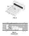
- the oblique rollersride on bearing surfaces supporting the conveyor belt 10 from below to push articles 12 conveyed atop the rollers 14 toward a side 16 of the belt as it advances, as shown in FIG 5 .
- the longer side 18 of a rectangular articleis leading, the article tends to rotate on contact with a stationary side rail 20 because of friction between the article and the side rail.
- the articleorients itself in the most stable position-with the shorter side 19 leading. In many applications, it is important for all articles to be conveyed and aligned with the longer edge leading.
- a roller belt conveyor with a fixed sideguardis known, for example, from US 2005 072 656 A1 .
- a conveyor embodying features of the inventionincluding a conveyor belt advancing in a direction of belt travel and having a plurality of rollers extending through its thickness.
- the rollersare arranged to rotate in a direction oblique to the direction of belt travel.
- a bearing surface underlying the conveyor belt in contact with the rollerscauses the rollers to rotate as the conveyor belt advances.
- the obliquely oriented rotating rollerstranslate articles conveyed atop the rollers toward a side of the conveyor belt.
- a sideguarddisposed along the side of the conveyor belt and extending above the rollers, advances with the conveyor belt in the direction of belt travel to receive conveyed articles translated toward the side.
- FIG. 1A portion of one version of a conveyor embodying features of the invention is shown in FIG. 1 .
- the conveyorincludes a conveyor belt 22 driven in a direction of belt travel 24.
- Salient portions of the rollers extending past the inner, or bottom, surface of the beltroll on roller bearing surfaces 30 below the belt.
- the rollersare arranged to rotate on axes 32 oblique to the direction of belt travel, defined, for example, by axles extending through bores in the rollers and retained in the body of the belt.
- the rollersrotate on their axes in an oblique direction 34, pushing articles conveyed atop the rollers toward a side 36 of the belt.
- a sideguard 38 at the side of the beltprovides a vertical registration surface 40, against which articles translated to the side are aligned.
- the beltis a modular plastic conveyor belt constructed of a series of rows 40 of belt modules 42. The rows are joined to an adjacent leading and trailing rows at hinge joints 44 that allow the belt to articulate about drive and idle sprockets and to backbend. (A hinge joint is formed in the conventional manner by the interleaved hinge eyes of adjacent rows journaling a hinge pin.)
- the sideguardconstitutes a series of individual plates 46.
- Each plateextends upward from the outer surface of a row at the side of the belt to which conveyed articles are directed by the rollers.
- the platesprovide the sideguard with the registration surface 40.
- the platesmay be mechanically attached to the belt modules or unitarily molded with them. Because the sideguard advances in the direction of belt travel with the belt, the sideguard engages articles translated to the side with les friction than a stationary conveyor side rail would. Consequently, a rectangular article being conveyed with its longer edge leading is less likely to rotate on contact with alignment structure at the side of the belt.
- the wheelsare mounted on posts 54 spaced along the length of the conveyor belt 22 at the side 36 of the belt toward which the article-supporting rollers 26 direct the articles.
- the postsextend perpendicularly upward from the outer surface 28 of the belt.
- the wheelsare stacked on the posts, which extend through central bores in the wheels.
- the postsserve as axles on which the portions of the wheels facing the belt rotate in the direction of belt travel.
- the wheelshave hubs 56 on one side. The hubs are used to space the larger-diameter wheel treads 58 in each stack on the post.
- the wheels on consecutive postsare stacked oppositely.
- the wheelsare stacked with the hubs above the treads; on odd-numbered posts, the wheels are stacked with the hubs below the treads.
- Thisallows the wheels to be closely packed in an array with the treads on one post vertically offset from the treads of the wheels on an adjacent post and with the wheels on adjacent posts overlapping vertically. In this way, the wheel array forms a low-friction alignment surface for the articles.
- the wheels in FIGS. 2 and 3are free to rotate on contact with the translated article. The low-friction rolling engagement allows the sideguard to receive translated articles without causing them to rotate.
- the wheels of the sideguard 50 in FIGS. 2 and 3can be rotated as shown by arrow 60 by contact with a vertical wheel bearing surface 62.
- the treads of the wheels 52roll on the stationary vertical bearing surface. This causes the wheels to rotate in the direction of belt travel at their points of contact with conveyed articles. Because articles are being translated by the belt rollers 26 with a component of motion relative to the belt in the direction of belt travel and because the wheels are also rotating in the direction of belt travel where they contact the articles, any tendency of the articles to rotate is eliminated.
- the individual linear wearstrips providing the roller bearing surfaces in FIG. 1may be replaced by a single bearing plate, as in FIGS. 2-4 , or by support rollers engaging the belt rollers from below in rolling contact.
- the sideguards describedare attached to the belt. But sideguards that move in the direction of belt travel at the side of the belt, but not physically attached to the belt may also be used.
- roller balls retained in a side wallcould be used as rotatable elements in the sideguard instead of wheels on posts.
- the beltcould be a flat belt as well as the modular belt used in describing the invention. So, as these few examples suggest, the scope of the claims is not meant to be limited to the preferred versions.
Landscapes
- Engineering & Computer Science (AREA)
- Mechanical Engineering (AREA)
- Rollers For Roller Conveyors For Transfer (AREA)
- Structure Of Belt Conveyors (AREA)
- Attitude Control For Articles On Conveyors (AREA)
- Belt Conveyors (AREA)
- Screw Conveyors (AREA)
- Framework For Endless Conveyors (AREA)
Abstract
Description
- The invention relates generally to power-driven conveyors and, more particularly, to conveyors using a conveyor belt having article-supporting rollers rotating oblique to the direction of belt travel to translate conveyed articles to a side of the conveyor.
- Conveyor belts with rollers extending through the thickness of the belt and arranged to rotate on axes oblique to the belt's direction of travel are used in conveyors to align articles along a side of the conveyor. The oblique rollers ride on bearing surfaces supporting the
conveyor belt 10 from below to pusharticles 12 conveyed atop therollers 14 toward aside 16 of the belt as it advances, as shown inFIG 5 . When thelonger side 18 of a rectangular article is leading, the article tends to rotate on contact with astationary side rail 20 because of friction between the article and the side rail. The article orients itself in the most stable position-with theshorter side 19 leading. In many applications, it is important for all articles to be conveyed and aligned with the longer edge leading. - Thus, there is a need for a belt conveyor that can align conveyed articles without changing their orientations. A roller belt conveyor with a fixed sideguard is known, for example, from
US 2005 072 656 A1 . - This need and other needs are satisfied by a conveyor embodying features of the invention including a conveyor belt advancing in a direction of belt travel and having a plurality of rollers extending through its thickness. The rollers are arranged to rotate in a direction oblique to the direction of belt travel. A bearing surface underlying the conveyor belt in contact with the rollers causes the rollers to rotate as the conveyor belt advances. The obliquely oriented rotating rollers translate articles conveyed atop the rollers toward a side of the conveyor belt. A sideguard, disposed along the side of the conveyor belt and extending above the rollers, advances with the conveyor belt in the direction of belt travel to receive conveyed articles translated toward the side.
- These features and aspects of the invention, as well as its advantages, are better understood by reference to the following description, appended claims, and accompanying drawings, in which:
FIG. 1 is an isometric view of a portion of a conveyor embodying features of the invention, including a sideguard comprising a series of plates;FIG. 2 is an isometric view of a portion of another version of conveyor embodying features of the invention, including a sideguard having stacks of wheels;FIG. 3 shows top plan, side elevation, and front elevation views of the conveyor ofFIG. 2 ;FIG. 4 is an isometric view of a portion of the conveyor ofFIG. 2 further showing a vertical bearing surface for rotating the sideguard wheels as the conveyor belt advances; andFIG. 5 is a top plan view of an oblique-roller belt operated in a conventional way in a conveyor with a stationary side rail.- A portion of one version of a conveyor embodying features of the invention is shown in
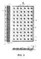
FIG. 1 . The conveyor includes aconveyor belt 22 driven in a direction ofbelt travel 24.Rollers 26 retained in the belt, such as incavities 27, extend past outer 28 and inner 29 belt surfaces. Salient portions of the rollers extending past the outer, or top, surface support articles conveyed on the belt. Salient portions of the rollers extending past the inner, or bottom, surface of the belt roll on roller bearingsurfaces 30 below the belt. The rollers are arranged to rotate onaxes 32 oblique to the direction of belt travel, defined, for example, by axles extending through bores in the rollers and retained in the body of the belt. As the belt advances in the direction of belt travel, the rollers rotate on their axes in anoblique direction 34, pushing articles conveyed atop the rollers toward aside 36 of the belt. A sideguard 38 at the side of the belt provides a vertical registration surface 40, against which articles translated to the side are aligned. In this example, the belt is a modular plastic conveyor belt constructed of a series of rows 40 ofbelt modules 42. The rows are joined to an adjacent leading and trailing rows athinge joints 44 that allow the belt to articulate about drive and idle sprockets and to backbend. (A hinge joint is formed in the conventional manner by the interleaved hinge eyes of adjacent rows journaling a hinge pin.) The sideguard constitutes a series ofindividual plates 46. Each plate extends upward from the outer surface of a row at the side of the belt to which conveyed articles are directed by the rollers. The plates provide the sideguard with the registration surface 40. The plates may be mechanically attached to the belt modules or unitarily molded with them. Because the sideguard advances in the direction of belt travel with the belt, the sideguard engages articles translated to the side with les friction than a stationary conveyor side rail would. Consequently, a rectangular article being conveyed with its longer edge leading is less likely to rotate on contact with alignment structure at the side of the belt. - A
sideguard 50 presenting an array of rotatable elements, such aswheels 52, is shown in the conveyor ofFIGS. 2 and3 . The wheels are mounted onposts 54 spaced along the length of theconveyor belt 22 at theside 36 of the belt toward which the article-supportingrollers 26 direct the articles. The posts extend perpendicularly upward from theouter surface 28 of the belt. The wheels are stacked on the posts, which extend through central bores in the wheels. The posts serve as axles on which the portions of the wheels facing the belt rotate in the direction of belt travel. The wheels have hubs 56 on one side. The hubs are used to space the larger-diameter wheel treads 58 in each stack on the post. The wheels on consecutive posts are stacked oppositely. On even-numbered posts, the wheels are stacked with the hubs above the treads; on odd-numbered posts, the wheels are stacked with the hubs below the treads. This allows the wheels to be closely packed in an array with the treads on one post vertically offset from the treads of the wheels on an adjacent post and with the wheels on adjacent posts overlapping vertically. In this way, the wheel array forms a low-friction alignment surface for the articles. The wheels inFIGS. 2 and3 are free to rotate on contact with the translated article. The low-friction rolling engagement allows the sideguard to receive translated articles without causing them to rotate. - As shown in
FIG. 4 , the wheels of thesideguard 50 inFIGS. 2 and3 can be rotated as shown byarrow 60 by contact with a verticalwheel bearing surface 62. As thebelt 22 advances in the direction of belt travel 24, the treads of thewheels 52 roll on the stationary vertical bearing surface. This causes the wheels to rotate in the direction of belt travel at their points of contact with conveyed articles. Because articles are being translated by thebelt rollers 26 with a component of motion relative to the belt in the direction of belt travel and because the wheels are also rotating in the direction of belt travel where they contact the articles, any tendency of the articles to rotate is eliminated. - Although the invention has been described in detail with respect to a few preferred versions, other versions are possible. For example, the individual linear wearstrips providing the roller bearing surfaces in
FIG. 1 may be replaced by a single bearing plate, as inFIGS. 2-4 , or by support rollers engaging the belt rollers from below in rolling contact. As another example, the sideguards described are attached to the belt. But sideguards that move in the direction of belt travel at the side of the belt, but not physically attached to the belt may also be used. As yet another example, roller balls retained in a side wall could be used as rotatable elements in the sideguard instead of wheels on posts. And, the belt could be a flat belt as well as the modular belt used in describing the invention. So, as these few examples suggest, the scope of the claims is not meant to be limited to the preferred versions.
Claims (6)
- A conveyor comprising:a conveyor belt (22) advancing in a direction of belt travel (24) and having a plurality of rollers (26) extending through the thickness of the conveyor belt arranged to rotate in a direction oblique to the direction of belt travel;a bearing surface (30) underlying the conveyor belt in contact with the rollers and causing the rollers to rotate as the conveyor belt advances to translate articles conveyed atop the rollers toward a side (36) of the conveyor belt;characterised in further comprising:a sideguard (38, 50) disposed along the side of the conveyor belt and extending above the rollers and advancing with the conveyor belt in the direction of belt travel to receive conveyed articles translated toward the side.
- A conveyor as in claim 1 wherein the sideguard comprises a series of plates (46) upstanding from the conveyor belt along the side.
- A conveyor as in claim 1 or 2 wherein the sideguard (38, 50) comprises a series of rotatable elements (52) rotatable in the direction of belt travel.
- A conveyor as in claim 3 further comprising a second bearing surface (62) proximate the side of the conveyor belt (36) and wherein the rotatable elements rotate by contact with the second bearing surface (62) as the conveyor belt advances.
- A conveyor as in claim 1 or 2 wherein the sideguard (38, 50) comprises a series of wheels (52) mounted to the conveyor belt for rotation on axes disposed perpendicular to the direction of belt travel.
- A conveyor as in claim 1 wherein the sideguard (38, 50) comprises a series of posts upstanding from the conveyor belt and one or more wheels received on each post for rotation about the post.
Applications Claiming Priority (2)
| Application Number | Priority Date | Filing Date | Title |
|---|---|---|---|
| US11/564,407US20080121495A1 (en) | 2006-11-29 | 2006-11-29 | Oblique-roller belt conveyor with sideguard |
| PCT/US2007/085947WO2008067473A1 (en) | 2006-11-29 | 2007-11-29 | Oblique-roller belt conveyor with sideguard |
Publications (2)
| Publication Number | Publication Date |
|---|---|
| EP2091849A1 EP2091849A1 (en) | 2009-08-26 |
| EP2091849B1true EP2091849B1 (en) | 2010-03-10 |
Family
ID=39092023
Family Applications (1)
| Application Number | Title | Priority Date | Filing Date |
|---|---|---|---|
| EP07854835ANot-in-forceEP2091849B1 (en) | 2006-11-29 | 2007-11-29 | Oblique-roller belt conveyor with sideguard |
Country Status (11)
| Country | Link |
|---|---|
| US (1) | US20080121495A1 (en) |
| EP (1) | EP2091849B1 (en) |
| JP (1) | JP2010510944A (en) |
| KR (1) | KR20090086217A (en) |
| CN (1) | CN101622181B (en) |
| AT (1) | ATE460363T1 (en) |
| BR (1) | BRPI0721017A2 (en) |
| DE (1) | DE602007005279D1 (en) |
| ES (1) | ES2341053T3 (en) |
| MX (1) | MX2009005585A (en) |
| WO (1) | WO2008067473A1 (en) |
Families Citing this family (18)
| Publication number | Priority date | Publication date | Assignee | Title |
|---|---|---|---|---|
| US7891481B2 (en)* | 2008-09-11 | 2011-02-22 | Laitram, L.L.C. | Conveyor belt for mounting oblique rollers on lateral rods |
| TWI429566B (en)* | 2012-01-05 | 2014-03-11 | Mas Automation Corp | Automatic Edge Method and Device for Plate - like Material |
| US8978879B2 (en)* | 2012-01-31 | 2015-03-17 | Laitram, L.L.C. | Multi-directional roller assembly |
| CN103738727A (en)* | 2013-11-27 | 2014-04-23 | 耐世特凌云驱动系统(芜湖)有限公司 | Automatic transmission and guiding device |
| CN103708169A (en)* | 2013-12-31 | 2014-04-09 | 江苏金铁人自动化科技有限公司 | Conveying belt |
| JP6524561B2 (en)* | 2014-03-13 | 2019-06-05 | レイトラム,エル.エル.シー. | Conveyor belt to turn articles |
| CN103910186B (en)* | 2014-03-31 | 2017-01-25 | 浙江德马科技股份有限公司 | Tension deviation adjusting method for tension deviation adjusting mechanism of bottom belt rubbing side-approaching machine |
| CN104495201A (en)* | 2014-12-20 | 2015-04-08 | 济南洁瑞热能科技有限公司 | Semi-automatic production line |
| US9212006B1 (en) | 2015-01-28 | 2015-12-15 | Laitram, L.L.C. | Conveyor with belt-actuated guide |
| US20170066595A1 (en)* | 2015-09-08 | 2017-03-09 | Laitram, L.L.C. | Conveyor guide wall with damping rollers |
| CN106081496A (en)* | 2016-06-16 | 2016-11-09 | 苏州安特实业有限公司 | A kind of flat sheet printing delivery device |
| EP3733567B1 (en)* | 2017-12-28 | 2025-02-05 | Itoh Denki Co., Ltd. | Cargo handling method |
| IT201800010440A1 (en)* | 2018-11-20 | 2020-05-20 | Nuova Sima Spa | STRAIGHTENING DEVICE TO STRAIGHTEN A SHEET-SHAPED ARTICLE WITH RESPECT TO A HANDLING DIRECTION |
| CN110589436A (en)* | 2019-10-08 | 2019-12-20 | 苏州鸿安机械有限公司 | A conveyor with guiding function |
| CN110645796B (en)* | 2019-10-23 | 2021-06-01 | 江苏理工学院 | Horizontal furnace is with high temperature resistant roll table |
| US20240199339A1 (en)* | 2021-05-11 | 2024-06-20 | Laitram, L.L.C. | Apparatus and method for activating conveyor belt rollers |
| CN113501250A (en)* | 2021-06-22 | 2021-10-15 | 无锡圣迈亿精密制造科技有限公司 | Balance wheel side-approaching machine |
| US11591162B2 (en) | 2021-06-22 | 2023-02-28 | Caterpillar Paving Products Inc. | Conveyor system for material transport on cold planer |
Family Cites Families (17)
| Publication number | Priority date | Publication date | Assignee | Title |
|---|---|---|---|---|
| US1729671A (en)* | 1927-07-21 | 1929-10-01 | Bell-Irving Robert | Load-deflecting device for conveyers |
| US3550756A (en)* | 1967-09-13 | 1970-12-29 | Kornylac Co | Conveyor having provision for discharging loads at an angle generally transverse to the line of travel on the conveyor |
| US5092447A (en)* | 1990-02-26 | 1992-03-03 | Wyard Industries, Inc. | Pattern-forming conveyor apparatus for container palletizing |
| US5101958A (en)* | 1991-05-09 | 1992-04-07 | Rapistan Corp. | Flowspitting conveyor |
| IT1293571B1 (en)* | 1997-07-04 | 1999-03-08 | Rexnord Marbett Spa | PARTITION WALL FOR INSTALLATION ABOVE A TRANSPORT BELT OF ITEMS SUCH AS BOTTLES AND SIMILAR |
| JP2000095321A (en)* | 1998-09-25 | 2000-04-04 | Taisho Pharmaceut Co Ltd | Conveyor |
| US6494312B2 (en)* | 1998-11-02 | 2002-12-17 | The Laitram Corporation | Modular roller-top conveyor belt with obliquely-arranged rollers |
| JP2001301951A (en)* | 2000-04-20 | 2001-10-31 | Teraoka Seiko Co Ltd | Conveyer, and packing/price-labelling machine provided therewith |
| US6766901B2 (en)* | 2001-07-19 | 2004-07-27 | Habasit Ag | Snap-on side guards |
| US6568522B1 (en)* | 2002-05-16 | 2003-05-27 | The Laitram Corporation | Accumulation system |
| US6923309B2 (en)* | 2003-10-03 | 2005-08-02 | Laitram, L.L.C. | Article-orienting conveyor |
| US6811021B1 (en)* | 2003-11-06 | 2004-11-02 | Laitram, L.L.C. | Plastic conveyor belt modules with unitary sideguards |
| US6968941B2 (en)* | 2003-11-21 | 2005-11-29 | Materials Handling Systems, Inc. | Apparatus and methods for conveying objects |
| US7111722B2 (en)* | 2004-08-13 | 2006-09-26 | Laitram, L.L.C. | Angled-roller belt conveyor |
| US7147097B2 (en)* | 2004-09-30 | 2006-12-12 | Laitram, L.L.C. | Transverse-roller-belt sorter with automated guide |
| JP3949685B2 (en)* | 2004-12-24 | 2007-07-25 | 株式会社椿本チエイン | Multi-function conveyor chain |
| US7249671B2 (en)* | 2005-05-06 | 2007-07-31 | Laitram, L.L.C. | Roller-belt conveyor for accumulating and moving articles laterally across the conveyor |
- 2006
- 2006-11-29USUS11/564,407patent/US20080121495A1/ennot_activeAbandoned
- 2007
- 2007-11-29KRKR1020097009882Apatent/KR20090086217A/ennot_activeCeased
- 2007-11-29BRBRPI0721017-5Apatent/BRPI0721017A2/ennot_activeIP Right Cessation
- 2007-11-29DEDE602007005279Tpatent/DE602007005279D1/enactiveActive
- 2007-11-29ATAT07854835Tpatent/ATE460363T1/ennot_activeIP Right Cessation
- 2007-11-29MXMX2009005585Apatent/MX2009005585A/enactiveIP Right Grant
- 2007-11-29EPEP07854835Apatent/EP2091849B1/ennot_activeNot-in-force
- 2007-11-29CNCN2007800440372Apatent/CN101622181B/ennot_activeExpired - Fee Related
- 2007-11-29JPJP2009539488Apatent/JP2010510944A/enactivePending
- 2007-11-29ESES07854835Tpatent/ES2341053T3/enactiveActive
- 2007-11-29WOPCT/US2007/085947patent/WO2008067473A1/enactiveApplication Filing
Also Published As
| Publication number | Publication date |
|---|---|
| JP2010510944A (en) | 2010-04-08 |
| ATE460363T1 (en) | 2010-03-15 |
| WO2008067473A1 (en) | 2008-06-05 |
| DE602007005279D1 (en) | 2010-04-22 |
| KR20090086217A (en) | 2009-08-11 |
| CN101622181A (en) | 2010-01-06 |
| EP2091849A1 (en) | 2009-08-26 |
| US20080121495A1 (en) | 2008-05-29 |
| MX2009005585A (en) | 2009-06-08 |
| CN101622181B (en) | 2012-08-22 |
| BRPI0721017A2 (en) | 2014-07-29 |
| ES2341053T3 (en) | 2010-06-14 |
Similar Documents
| Publication | Publication Date | Title |
|---|---|---|
| EP2091849B1 (en) | Oblique-roller belt conveyor with sideguard | |
| EP1316519B1 (en) | Split belt modules in modular conveyor belts | |
| EP2475600B1 (en) | Conveyors, belts, and modules with actuated rollers | |
| EP1868924B1 (en) | Belt conveyor with variable angled rollers | |
| EP2621835B1 (en) | Conveyor, belt, and module having multi-directional wheels | |
| US7775345B2 (en) | Conveyor and belt with clutch-driven flights | |
| KR101930107B1 (en) | Transverse driven-roller belt and conveyor | |
| US20080271978A1 (en) | Transverse-roller belts and modules | |
| EP2509895A1 (en) | Conveyor transfer system with floating transfer platform | |
| US8678180B2 (en) | Modular conveyor belt with extended raised ribs | |
| EP2129603A2 (en) | Split-level singulator | |
| US7357246B2 (en) | Belt conveyor having self-clearing flights | |
| US7527145B2 (en) | Low-friction conveyor | |
| US11905118B2 (en) | Roller belt with support edges |
Legal Events
| Date | Code | Title | Description |
|---|---|---|---|
| PUAI | Public reference made under article 153(3) epc to a published international application that has entered the european phase | Free format text:ORIGINAL CODE: 0009012 | |
| 17P | Request for examination filed | Effective date:20090427 | |
| AK | Designated contracting states | Kind code of ref document:A1 Designated state(s):AT BE BG CH CY CZ DE DK EE ES FI FR GB GR HU IE IS IT LI LT LU LV MC MT NL PL PT RO SE SI SK TR | |
| GRAP | Despatch of communication of intention to grant a patent | Free format text:ORIGINAL CODE: EPIDOSNIGR1 | |
| GRAS | Grant fee paid | Free format text:ORIGINAL CODE: EPIDOSNIGR3 | |
| GRAA | (expected) grant | Free format text:ORIGINAL CODE: 0009210 | |
| AK | Designated contracting states | Kind code of ref document:B1 Designated state(s):AT BE BG CH CY CZ DE DK EE ES FI FR GB GR HU IE IS IT LI LT LU LV MC MT NL PL PT RO SE SI SK TR | |
| REG | Reference to a national code | Ref country code:GB Ref legal event code:FG4D | |
| REG | Reference to a national code | Ref country code:CH Ref legal event code:EP | |
| REG | Reference to a national code | Ref country code:IE Ref legal event code:FG4D | |
| REF | Corresponds to: | Ref document number:602007005279 Country of ref document:DE Date of ref document:20100422 Kind code of ref document:P | |
| REG | Reference to a national code | Ref country code:NL Ref legal event code:T3 | |
| REG | Reference to a national code | Ref country code:ES Ref legal event code:FG2A Ref document number:2341053 Country of ref document:ES Kind code of ref document:T3 | |
| PG25 | Lapsed in a contracting state [announced via postgrant information from national office to epo] | Ref country code:LT Free format text:LAPSE BECAUSE OF FAILURE TO SUBMIT A TRANSLATION OF THE DESCRIPTION OR TO PAY THE FEE WITHIN THE PRESCRIBED TIME-LIMIT Effective date:20100310 | |
| LTIE | Lt: invalidation of european patent or patent extension | Effective date:20100310 | |
| PG25 | Lapsed in a contracting state [announced via postgrant information from national office to epo] | Ref country code:SI Free format text:LAPSE BECAUSE OF FAILURE TO SUBMIT A TRANSLATION OF THE DESCRIPTION OR TO PAY THE FEE WITHIN THE PRESCRIBED TIME-LIMIT Effective date:20100310 Ref country code:AT Free format text:LAPSE BECAUSE OF FAILURE TO SUBMIT A TRANSLATION OF THE DESCRIPTION OR TO PAY THE FEE WITHIN THE PRESCRIBED TIME-LIMIT Effective date:20100310 Ref country code:FI Free format text:LAPSE BECAUSE OF FAILURE TO SUBMIT A TRANSLATION OF THE DESCRIPTION OR TO PAY THE FEE WITHIN THE PRESCRIBED TIME-LIMIT Effective date:20100310 Ref country code:LV Free format text:LAPSE BECAUSE OF FAILURE TO SUBMIT A TRANSLATION OF THE DESCRIPTION OR TO PAY THE FEE WITHIN THE PRESCRIBED TIME-LIMIT Effective date:20100310 Ref country code:PL Free format text:LAPSE BECAUSE OF FAILURE TO SUBMIT A TRANSLATION OF THE DESCRIPTION OR TO PAY THE FEE WITHIN THE PRESCRIBED TIME-LIMIT Effective date:20100310 | |
| PG25 | Lapsed in a contracting state [announced via postgrant information from national office to epo] | Ref country code:CY Free format text:LAPSE BECAUSE OF FAILURE TO SUBMIT A TRANSLATION OF THE DESCRIPTION OR TO PAY THE FEE WITHIN THE PRESCRIBED TIME-LIMIT Effective date:20100310 Ref country code:BE Free format text:LAPSE BECAUSE OF FAILURE TO SUBMIT A TRANSLATION OF THE DESCRIPTION OR TO PAY THE FEE WITHIN THE PRESCRIBED TIME-LIMIT Effective date:20100310 Ref country code:EE Free format text:LAPSE BECAUSE OF FAILURE TO SUBMIT A TRANSLATION OF THE DESCRIPTION OR TO PAY THE FEE WITHIN THE PRESCRIBED TIME-LIMIT Effective date:20100310 Ref country code:GR Free format text:LAPSE BECAUSE OF FAILURE TO SUBMIT A TRANSLATION OF THE DESCRIPTION OR TO PAY THE FEE WITHIN THE PRESCRIBED TIME-LIMIT Effective date:20100611 Ref country code:RO Free format text:LAPSE BECAUSE OF FAILURE TO SUBMIT A TRANSLATION OF THE DESCRIPTION OR TO PAY THE FEE WITHIN THE PRESCRIBED TIME-LIMIT Effective date:20100310 Ref country code:SE Free format text:LAPSE BECAUSE OF FAILURE TO SUBMIT A TRANSLATION OF THE DESCRIPTION OR TO PAY THE FEE WITHIN THE PRESCRIBED TIME-LIMIT Effective date:20100310 | |
| PG25 | Lapsed in a contracting state [announced via postgrant information from national office to epo] | Ref country code:SK Free format text:LAPSE BECAUSE OF FAILURE TO SUBMIT A TRANSLATION OF THE DESCRIPTION OR TO PAY THE FEE WITHIN THE PRESCRIBED TIME-LIMIT Effective date:20100310 Ref country code:CZ Free format text:LAPSE BECAUSE OF FAILURE TO SUBMIT A TRANSLATION OF THE DESCRIPTION OR TO PAY THE FEE WITHIN THE PRESCRIBED TIME-LIMIT Effective date:20100310 Ref country code:BG Free format text:LAPSE BECAUSE OF FAILURE TO SUBMIT A TRANSLATION OF THE DESCRIPTION OR TO PAY THE FEE WITHIN THE PRESCRIBED TIME-LIMIT Effective date:20100610 Ref country code:IS Free format text:LAPSE BECAUSE OF FAILURE TO SUBMIT A TRANSLATION OF THE DESCRIPTION OR TO PAY THE FEE WITHIN THE PRESCRIBED TIME-LIMIT Effective date:20100710 | |
| PLBE | No opposition filed within time limit | Free format text:ORIGINAL CODE: 0009261 | |
| STAA | Information on the status of an ep patent application or granted ep patent | Free format text:STATUS: NO OPPOSITION FILED WITHIN TIME LIMIT | |
| PG25 | Lapsed in a contracting state [announced via postgrant information from national office to epo] | Ref country code:PT Free format text:LAPSE BECAUSE OF FAILURE TO SUBMIT A TRANSLATION OF THE DESCRIPTION OR TO PAY THE FEE WITHIN THE PRESCRIBED TIME-LIMIT Effective date:20100712 Ref country code:DK Free format text:LAPSE BECAUSE OF FAILURE TO SUBMIT A TRANSLATION OF THE DESCRIPTION OR TO PAY THE FEE WITHIN THE PRESCRIBED TIME-LIMIT Effective date:20100310 | |
| 26N | No opposition filed | Effective date:20101213 | |
| PG25 | Lapsed in a contracting state [announced via postgrant information from national office to epo] | Ref country code:MC Free format text:LAPSE BECAUSE OF NON-PAYMENT OF DUE FEES Effective date:20101130 | |
| PG25 | Lapsed in a contracting state [announced via postgrant information from national office to epo] | Ref country code:IE Free format text:LAPSE BECAUSE OF NON-PAYMENT OF DUE FEES Effective date:20101129 | |
| PG25 | Lapsed in a contracting state [announced via postgrant information from national office to epo] | Ref country code:IT Free format text:LAPSE BECAUSE OF NON-PAYMENT OF DUE FEES Effective date:20101129 Ref country code:MT Free format text:LAPSE BECAUSE OF FAILURE TO SUBMIT A TRANSLATION OF THE DESCRIPTION OR TO PAY THE FEE WITHIN THE PRESCRIBED TIME-LIMIT Effective date:20100310 | |
| REG | Reference to a national code | Ref country code:CH Ref legal event code:PL | |
| PG25 | Lapsed in a contracting state [announced via postgrant information from national office to epo] | Ref country code:CH Free format text:LAPSE BECAUSE OF NON-PAYMENT OF DUE FEES Effective date:20111130 Ref country code:LI Free format text:LAPSE BECAUSE OF NON-PAYMENT OF DUE FEES Effective date:20111130 | |
| PG25 | Lapsed in a contracting state [announced via postgrant information from national office to epo] | Ref country code:HU Free format text:LAPSE BECAUSE OF FAILURE TO SUBMIT A TRANSLATION OF THE DESCRIPTION OR TO PAY THE FEE WITHIN THE PRESCRIBED TIME-LIMIT Effective date:20100911 Ref country code:LU Free format text:LAPSE BECAUSE OF NON-PAYMENT OF DUE FEES Effective date:20101129 | |
| PGFP | Annual fee paid to national office [announced via postgrant information from national office to epo] | Ref country code:NL Payment date:20121112 Year of fee payment:6 | |
| REG | Reference to a national code | Ref country code:NL Ref legal event code:V1 Effective date:20140601 | |
| PG25 | Lapsed in a contracting state [announced via postgrant information from national office to epo] | Ref country code:NL Free format text:LAPSE BECAUSE OF NON-PAYMENT OF DUE FEES Effective date:20140601 | |
| REG | Reference to a national code | Ref country code:FR Ref legal event code:PLFP Year of fee payment:9 | |
| PGFP | Annual fee paid to national office [announced via postgrant information from national office to epo] | Ref country code:ES Payment date:20151113 Year of fee payment:9 | |
| REG | Reference to a national code | Ref country code:FR Ref legal event code:PLFP Year of fee payment:10 | |
| REG | Reference to a national code | Ref country code:FR Ref legal event code:PLFP Year of fee payment:11 | |
| PG25 | Lapsed in a contracting state [announced via postgrant information from national office to epo] | Ref country code:ES Free format text:LAPSE BECAUSE OF NON-PAYMENT OF DUE FEES Effective date:20161130 | |
| REG | Reference to a national code | Ref country code:FR Ref legal event code:PLFP Year of fee payment:12 | |
| REG | Reference to a national code | Ref country code:ES Ref legal event code:FD2A Effective date:20181120 | |
| PGFP | Annual fee paid to national office [announced via postgrant information from national office to epo] | Ref country code:FR Payment date:20191029 Year of fee payment:13 Ref country code:IT Payment date:20191113 Year of fee payment:13 | |
| PGFP | Annual fee paid to national office [announced via postgrant information from national office to epo] | Ref country code:TR Payment date:20191025 Year of fee payment:13 | |
| PG25 | Lapsed in a contracting state [announced via postgrant information from national office to epo] | Ref country code:FR Free format text:LAPSE BECAUSE OF NON-PAYMENT OF DUE FEES Effective date:20201130 Ref country code:IT Free format text:LAPSE BECAUSE OF NON-PAYMENT OF DUE FEES Effective date:20201129 | |
| PGFP | Annual fee paid to national office [announced via postgrant information from national office to epo] | Ref country code:DE Payment date:20211013 Year of fee payment:15 Ref country code:GB Payment date:20211028 Year of fee payment:15 | |
| PG25 | Lapsed in a contracting state [announced via postgrant information from national office to epo] | Ref country code:TR Free format text:LAPSE BECAUSE OF NON-PAYMENT OF DUE FEES Effective date:20201129 | |
| REG | Reference to a national code | Ref country code:DE Ref legal event code:R119 Ref document number:602007005279 Country of ref document:DE | |
| GBPC | Gb: european patent ceased through non-payment of renewal fee | Effective date:20221129 | |
| PG25 | Lapsed in a contracting state [announced via postgrant information from national office to epo] | Ref country code:GB Free format text:LAPSE BECAUSE OF NON-PAYMENT OF DUE FEES Effective date:20221129 Ref country code:DE Free format text:LAPSE BECAUSE OF NON-PAYMENT OF DUE FEES Effective date:20230601 |